Page 1 of 26
CERTIFICATE OF CONFORMITY
For the following information Ref. File No.: C1M1503003
Product Intel® Compute Stick
Test Model STCK1A32WFC
Family Product Code xSTCK1xFCx (Where x may be a combination of alphanumeric characters or blank)
Brand Name Intel®
Applicant INTEL CORP.
Test Report Number EM-RF150018
Standards ETSI EN 300 328 V.1.8.1:2012-06 We hereby certify that the above product has been tested by us with the listed standards and found in compliance with the council R&TTE directive 1999/5/EC. The test data & results are issued on the R&TTE-RF test report no. EM-RF150018. Signature Ben Cheng/Manager Date: 2015. 03. 18 Test Laboratory: AUDIX Technology Corporation, EMC Department Web Site: www.audixtech.com The statement is based on a single evaluation of one sample of the above-mentioned products. It does not imply an assessment of the whole production and does not permit the use of the test lab logo.
Page 2 of 26
AUDIX Technology Corporation Report No. EM-RF150018
ETSI EN 300 328
OUTPUT POWER & SPURIOUS EMISSIONS TEST REPORT
INTEL CORP.
Intel® Compute Stick
Test Model: STCK1A32WFC
Family Product Code: xSTCK1xFCx (Where x may be a combination of alphanumeric characters or blank)
Brand: Intel®
Prepared for : INTEL CORP.
HF3-96, 5200 NE ELAM YOUNG PKY, HILLSBORO, OR 97124 USA
Prepared By : AUDIX Technology Corporation EMC Department
No. 53-11, Dingfu, Linkou Dist., New Taipei City 244, Taiwan, R.O.C. Tel : (02) 2609-9301, 2609-2133 Fax : (02) 2609-9303
File Number : C1M1503003 Report Number : EM-RF150018 Date of Test : 2015. 03. 09 Date of Report : 2015. 03. 18
Page 3 of 26
AUDIX Technology Corporation Report No. EM-RF150018
TABLE OF CONTENTS
Description Page TEST REPORT VERIFICATION ................................................................................................................. 4 1.DESCRIPTION OF REVISION HISTORY ..................................................................................... 5 2.SUMMARY OF MEASUREMENTS AND RESULTS ................................................................... 6
2.1.Compliance with ETSI EN 300 328 ......................................................................................................... 6 3.GENERAL INFORMATION ..................................................................................................................... 7
3.1.Description of Device (EUT) ................................................................................................................... 7 3.2.Descriptions of Key Components and Operating Modes ......................................................................... 8 3.3.Tested Supporting System Details ......................................................................................................... 10 3.4.Block Diagram of Test Setup ................................................................................................................. 10 3.5.Description of Test Facility .................................................................................................................... 11 3.6.Measurement Uncertainty ...................................................................................................................... 11
4.MEASUREMENTS OF TRANSMITTER PARAMETERS ................................................................ 12 4.1.RF Output Power .................................................................................................................................... 12 4.2.Transmitter Unwanted Emission in the spurious Domain (Radiated) .................................................... 15
5.RECEIVER SPURIOUS EMISSIONS ............................................................................................ 22 5.1.Spurious Emissions (Radiated) .............................................................................................................. 22
6.PHOTOGRAPHS OF MEASUREMENT ....................................................................................... 25 6.1.Photo of RF Output Power ..................................................................................................................... 25 6.2.Photos of Spurious Emissions Measurement ......................................................................................... 26
APPENDIX I (PHOTOS OF EUT)
Page 4 of 26
AUDIX Technology Corporation Report No. EM-RF150018
TEST REPORT VERIFICATION
Applicant : INTEL CORP. EUT Description : Intel® Compute Stick
(A) Test Model : STCK1A32WFC (B) Family Product Code : xSTCK1xFCx
(Where x may be a combination of alphanumeric characters or blank)
(C) Serial No. : N/A (D) Brand : Intel® (E) Power Supply : DC 5V, 2A (F) Test Voltage : AC 230V, 50Hz (Via AC Adapter)
Measurement Standards Used: ETSI EN 300 328 V.1.8.1:2012-06 The device described above was tested by AUDIX Technology Corporation. The measurement results were contained in this test report and AUDIX Technology Corporation was assumed full responsibility for the accuracy and completeness of these measurements. Also, this report shows that the EUT to be technically compliance with the ETSI EN 300 328 requirements. This report applies to above tested sample only and shall not be reproduced in part without written approval of AUDIX Technology Corporation. Date of Test: 2015. 03. 09 Date of Report: 2015. 03. 18
Producer:
(Annie Yu/Administrator)
Signatory:
(Ben Cheng/Manager)
Page 5 of 26
AUDIX Technology Corporation Report No. EM-RF150018
1. DESCRIPTION OF REVISION HISTORY
Edition No. Date of Rev. Revision Summary Report No.
0 2015. 03. 18 Original Report EM-RF150018
Page 6 of 26
AUDIX Technology Corporation Report No. EM-RF150018
2. SUMMARY OF MEASUREMENTS AND RESULTS
2.1. Compliance with ETSI EN 300 328
CLAUSE (ETSI 300 328)
TEST PARAMETER RESULTS
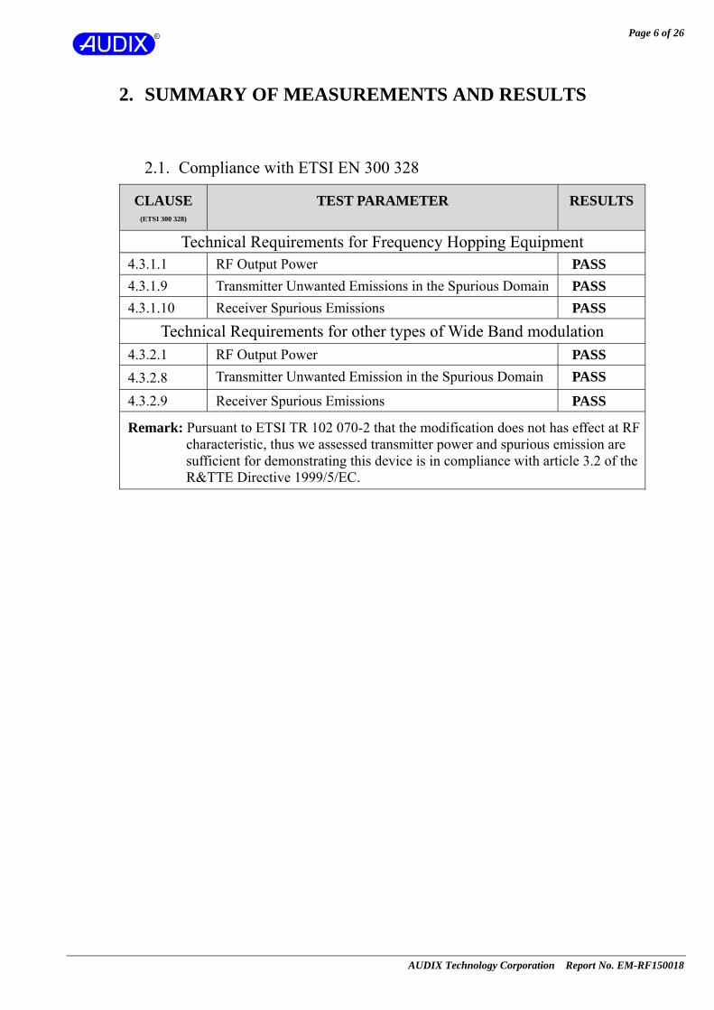
Technical Requirements for Frequency Hopping Equipment 4.3.1.1 RF Output Power PASS 4.3.1.9 Transmitter Unwanted Emissions in the Spurious Domain PASS 4.3.1.10 Receiver Spurious Emissions PASS
Technical Requirements for other types of Wide Band modulation 4.3.2.1 RF Output Power PASS 4.3.2.8 Transmitter Unwanted Emission in the Spurious Domain PASS
4.3.2.9 Receiver Spurious Emissions PASS
Remark: Pursuant to ETSI TR 102 070-2 that the modification does not has effect at RF characteristic, thus we assessed transmitter power and spurious emission are sufficient for demonstrating this device is in compliance with article 3.2 of the R&TTE Directive 1999/5/EC.
Page 7 of 26
AUDIX Technology Corporation Report No. EM-RF150018
3. GENERAL INFORMATION
3.1. Description of Device (EUT) Product Intel® Compute Stick
Test Model STCK1A32WFC
Family Product Code xSTCK1xFCx (Where x may be a combination of alphanumeric characters or blank)
Serial Number N/A
Brand Intel®
Applicant INTEL CORP. HF3-96, 5200 NE ELAM YOUNG PKY, HILLSBORO, OR 97124 USA
Power Supply Rating Refer to AC adapter rating.
Fundamental Range 802.11b/g/n-HT20: 2412MHz ~ 2472MHz 802.11n-HT40: 2422MHz ~ 2462MHz Bluetooth and BLE: 2402MHz ~ 2480MHz
Frequency Channel
802.11b/g/n-HT20: 13 channels 802.11n-HT40: 7 channels Bluetooth: 79 channels BLE: 40 channels
Radio Technology
802.11b: DSSS Modulation (DBPSK/DQPSK/CCK) 802.11g: OFDM Modulation (BPSK/QPSK/16QAM/64QAM) 802.11n: OFDM Modulation (BPSK/QPSK/16QAM/64QAM) Bluetooth: FHSS (GFSK,π/4DQPSK, 8-DPSK) BLE: GFSK
Data Transfer Rate
802.11b: 1/2/5.5/11Mbps 802.11g: 6/9/12/18/24/36/48/54Mbps 802.11n: up to 150Mbps Bluetooth: 1/2/3Mbps BLE: 1Mbps
Antenna Type PIFA Antenna, Linking Technology Inc., M/N T-543-8321061
Antenna Gain 2.95dBi
Interface Ports HDMI Port *1 USB 2.0 Port *1 Micro USB 2.0 *1 Micro SD Card Slot *1
Date of Receipt of Sample 2015. 02. 26
Page 8 of 26
AUDIX Technology Corporation Report No. EM-RF150018
3.2. Descriptions of Key Components and Operating Modes
3.2.1. List of key components under test
Item Supplier Model / Type Character
Mother Board Intel STCK1A32WFC-IS With 32G eMMC
and 2GB memory
STCK1A8LFC-IS With 8G Emmc and 1GB memory
CPU (Socket: BGA592) Intel Intel® Atom™ CPU
[email protected] 1.33 GHz
Memory HYNIX
H5TC4G63AFR-PBA 2GB IC DDR3L SDRAM.256M*16
H5TC2G63FFR 1GB IC DDR3L SDRAM.128M*16
Micron MT41K128M16JT 1GB IC DDR3L SDRAM.128M*16
eMMC
SAMSUNG KLMBG4GEND-B031 32G
KLM8G1GEAC-B031 8G
TOSHIBA THGBMBG8D4KBAIR 32G
THGBMBG6D1KBAIL 8G
KINGSTON EMMC32G-S100-WB9 32G
EMMC08G-S100 8G
Wi-Fi +BT Combo Module REALTEK RTL8723BS
802.11 b/g/n Wireless LAN Bluetooth 2.1+EDR/BT4.0 for BT peripherals
Antenna Linking Technology Inc.
T-543-8321061 PIFA Antenna, 2.95dBi
AC Adapter Asian Power Device Inc.
WB-10G05R (Wall-mount, 2C)
AC Input: 100-240V~, 50-60Hz, 0.4A Max. DC Output: 5V, 2A
Micro USB Cable Shielded, Detachable, 1.0m
HDMI Cable Shielded, Detachable, 0.2m
Remark: For a more detailed features description, please refer to the manufacturer’s specifications or the user manual.
Page 9 of 26
AUDIX Technology Corporation Report No. EM-RF150018
3.2.2. List of operating modes under test
SKU #1 ~ 14 1 2 3 4 5 6 7 8 9 10 11 12 13 14
Mother Board Intel, STCK1A32WFC-IS V V V V V V V V V V V V V VCPU Intel, Z3735F V V V V V V V V V V V V V VMemory HYNIX, H5TC4G63AFR-PBA V V V V V V V V V V V V V V
eMMC
SAMSUNG, KLMBG4GEND-B031 V V V V V V V V V V V VTOSHIBA, THGBMBG8D4KBAIR V KINGSTON, EMMC32G-S100-WB9 V
Wi-Fi +BT Combo Module REALTEK, RTL8723BS V V V V V V V V V V V V V V
Resolution
1920*1200 60Hz 32bit 200% Font Size V V V V V V V V1920*1080 60Hz 32bit 200% Font Size V 1600*1200 60Hz 32bit 150% Font Size V 1400*1050 60Hz 32bit 150% Font Size V 1280*1024 75Hz 32bit 125% Font Size V 1024*768 75Hz 32bit 100% Font Size V 800*600 75Hz 32bit 100% Font Size V
Cable with HDMI Cable V V V V V V V V V V V V Vwithout HDMI Cable V
AC Adapter Asian, WB-10G05R V V V V V V V V V V V V V V
Test Voltage
AC 100V, 50Hz V
AC 110V, 60Hz V V V V V V V V V V
AC 120V, 60Hz V
AC 220V, 60Hz V
AC 230V, 50Hz V
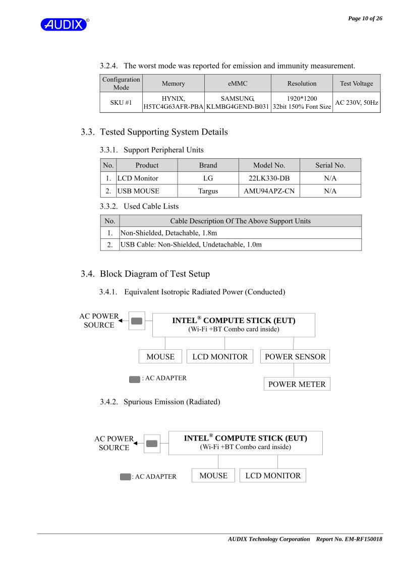
3.2.3. According to radiated emission pre-test result, the EUT collocates with following worst components (SKU #1), which are used to establish a basic configuration of system during test:
Item Supplier Model / Type Character
Mother Board Intel STCK1A32WFC-IS With 32G eMMC and 2GB memory
CPU (Socket: BGA592) Intel Intel® Atom™ CPU
[email protected] 1.33 GHz
Memory HYNIX H5TC4G63AFR-PBA 2GB IC DDR3L SDRAM.256M*16
eMMC SAMSUNG KLMBG4GEND-B031 32G
Wi-Fi +BT Combo Module REALTEK RTL8723BS
802.11 b/g/n Wireless LAN Bluetooth 2.1+EDR/BT4.0 for BT peripherals
Antenna Linking Technology Inc.
T-543-8321061 PIFA Antenna, 2.95dBi
AC Adapter Asian Power Device Inc.
WB-10G05R (Wall-mount, 2C)
AC Input: 100-240V~, 50-60Hz, 0.4A Max.DC Output: 5V, 2A
Micro USB Cable Shielded, Detachable, 1.0m HDMI Cable Shielded, Detachable, 0.2m
Page 10 of 26
AUDIX Technology Corporation Report No. EM-RF150018
3.2.4. The worst mode was reported for emission and immunity measurement.
Configuration Mode Memory eMMC Resolution Test Voltage
SKU #1 HYNIX, H5TC4G63AFR-PBA
SAMSUNG, KLMBG4GEND-B031
1920*1200 32bit 150% Font Size AC 230V, 50Hz
3.3. Tested Supporting System Details
3.3.1. Support Peripheral Units
No. Product Brand Model No. Serial No.
1. LCD Monitor LG 22LK330-DB N/A
2. USB MOUSE Targus AMU94APZ-CN N/A
3.3.2. Used Cable Lists
No. Cable Description Of The Above Support Units 1. Non-Shielded, Detachable, 1.8m 2. USB Cable: Non-Shielded, Undetachable, 1.0m
3.4. Block Diagram of Test Setup
3.4.1. Equivalent Isotropic Radiated Power (Conducted)
3.4.2. Spurious Emission (Radiated)
POWER SENSOR
POWER METER
AC POWERSOURCE
MOUSE LCD MONITOR
INTEL® COMPUTE STICK (EUT) (Wi-Fi +BT Combo card inside)
MOUSE LCD MONITOR
INTEL® COMPUTE STICK (EUT) (Wi-Fi +BT Combo card inside)
: AC ADAPTER
: AC ADAPTER
AC POWER SOURCE
Page 11 of 26
AUDIX Technology Corporation Report No. EM-RF150018
3.5. Description of Test Facility Name of Firm : AUDIX Technology Corporation EMC Department No. 53-11, Dingfu, Linkou Dist., New Taipei City 244, Taiwan, R.O.C. Test Site : No. 53-11, Dingfu, Linkou Dist., New Taipei City 244, Taiwan, R.O.C. NVLAP Lab. Code : 200077-0 TAF Accreditation No : 1724
3.6. Measurement Uncertainty Test Item Uncertainty RF Output Power ±0.34dB
Spurious Emission (RE)
30MHz ~ 1000MHz ± 0.20dB
Above 1GHz ± 1.60dB
Remark:Uncertainty = kuc(y)
Page 12 of 26
AUDIX Technology Corporation Report No. EM-RF150018
4. MEASUREMENTS OF TRANSMITTER PARAMETERS
4.1. RF Output Power
4.1.1. Test Equipment
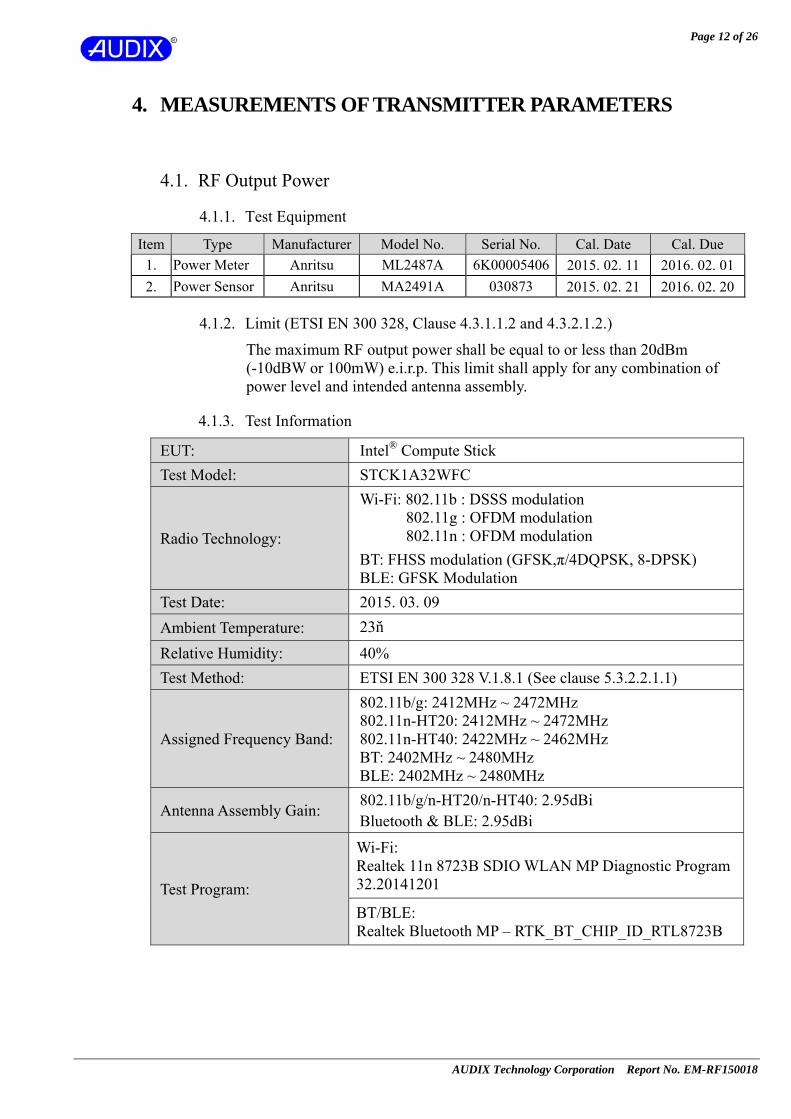
Item Type Manufacturer Model No. Serial No. Cal. Date Cal. Due 1. Power Meter Anritsu ML2487A 6K00005406 2015. 02. 11 2016. 02. 012. Power Sensor Anritsu MA2491A 030873 2015. 02. 21 2016. 02. 20
4.1.2. Limit (ETSI EN 300 328, Clause 4.3.1.1.2 and 4.3.2.1.2.)
The maximum RF output power shall be equal to or less than 20dBm (-10dBW or 100mW) e.i.r.p. This limit shall apply for any combination of power level and intended antenna assembly.
4.1.3. Test Information
EUT: Intel® Compute Stick Test Model: STCK1A32WFC
Radio Technology:
Wi-Fi: 802.11b : DSSS modulation 802.11g : OFDM modulation 802.11n : OFDM modulation
BT: FHSS modulation (GFSK,π/4DQPSK, 8-DPSK) BLE: GFSK Modulation
Test Date: 2015. 03. 09 Ambient Temperature: 23℃
Relative Humidity: 40% Test Method: ETSI EN 300 328 V.1.8.1 (See clause 5.3.2.2.1.1)
Assigned Frequency Band:
802.11b/g: 2412MHz ~ 2472MHz 802.11n-HT20: 2412MHz ~ 2472MHz 802.11n-HT40: 2422MHz ~ 2462MHz BT: 2402MHz ~ 2480MHz BLE: 2402MHz ~ 2480MHz
Antenna Assembly Gain: 802.11b/g/n-HT20/n-HT40: 2.95dBi Bluetooth & BLE: 2.95dBi
Test Program:
Wi-Fi: Realtek 11n 8723B SDIO WLAN MP Diagnostic Program 32.20141201
BT/BLE: Realtek Bluetooth MP – RTK_BT_CHIP_ID_RTL8723B
Page 13 of 26
AUDIX Technology Corporation Report No. EM-RF150018
4.1.4. Type of Network: IEEE 802.11b
Frequency (MHz)
Average Conducted Power(dBm) Antenna Gain
(dBi) EIRP (dBm) Chin 0
2412 15.85 2.95 18.80 2442 15.98 2.95 18.93 2472 16.01 2.95 18.96
Note 1: EIRP =Average Conducted Power + Antenna Gain 2: Average power as defined in clause 5.7.2.2. step 2 (P).
4.1.5. Type of Network: IEEE 802.11g
Frequency (MHz)
Average Conducted Power(dBm) Antenna Gain
(dBi) EIRP (dBm) Chin 0
2412 14.17 2.95 17.12 2442 13.89 2.95 16.84 2472 14.12 2.95 17.07
Note 1: EIRP =Average Conducted Power + Antenna Gain 2: Average power as defined in clause 5.7.2.2. step 2 (P).
4.1.6. Type of Network: IEEE 802.11n-HT20
Frequency (MHz)
Average Conducted Power(dBm) Antenna Gain
(dBi) EIRP (dBm) Chin 0
2412 13.11 2.95 16.06 2442 13.00 2.95 15.95 2472 12.97 2.95 15.92
Note 1: EIRP =Total Average Conducted Power + Antenna Gain 2: Average power as defined in clause 5.7.2.2. step 2 (P).
4.1.7. Type of Network: IEEE 802.11n-HT40
Frequency (MHz)
Average Conducted Power(dBm) Antenna Gain
(dBi) EIRP (dBm) Chin 0
2422 13.17 2.95 16.12 2442 13.09 2.95 16.04 2462 12.93 2.95 15.88
Note 1: EIRP =Total Average Conducted Power + Antenna Gain 2: Average power as defined in clause 5.7.2.2. step 2 (P).
Page 14 of 26
AUDIX Technology Corporation Report No. EM-RF150018
4.1.8. Type of Network: Bluetooth (GFSK)
Frequency (MHz)
Average Conducted Power(dBm) Antenna Gain
(dBi) EIRP (dBm) Chin 0
2402 4.19 2.95 7.14 2441 4.51 2.95 7.46 2480 1.64 2.95 4.59
Note 1: EIRP =Average Conducted Power + Antenna Gain 2: Average power as defined in clause 5.7.2.2. step 2 (P).
4.1.9. Type of Network: Bluetooth (8DPSK)
Frequency (MHz)
Average Conducted Power(dBm) Antenna Gain
(dBi) EIRP (dBm) Chin 0
2402 5.01 2.95 7.96 2441 5.35 2.95 8.30 2480 2.57 2.95 5.52
Note 1: EIRP =Average Conducted Power + Antenna Gain 2: Average power as defined in clause 5.7.2.2. step 2 (P).
4.1.10. Type of Network: BLE
Frequency (MHz)
Average Conducted Power(dBm) Antenna Gain
(dBi) EIRP (dBm) Chin 0
2402 5.01 2.95 7.96 2440 5.21 2.95 8.16 2480 5.00 2.95 7.95
Note 1: EIRP =Average Conducted Power + Antenna Gain 2: Average power as defined in clause 5.7.2.2. step 2 (P).
Page 15 of 26
AUDIX Technology Corporation Report No. EM-RF150018
4.2. Transmitter Unwanted Emission in the spurious Domain (Radiated)
4.2.1. Test Equipment
4.2.1.1. For Radiated Spurious Emissions (for 30MHz-1GHz)
Item Type Manufacturer Model No. Serial No. Cal. Date Cal. Due 1. Spectrum Analyzer Agilent E4446A US44300366 2014. 08. 21 2015. 08. 202. Amplifier Sonoma 310N 187161 2014. 06. 17 2015. 06. 163. Bilog Antenna Schaffner CBL6112B 2736 2015. 02. 27 2016. 02. 26
4.2.1.2. For Radiated Spurious Emissions (for 1GHz-12.75GHz)
Item Type Manufacturer Model No. Serial No. Cal. Date Cal. Due 1. Spectrum Analyzer Agilent E4446A US44300366 2014. 08. 21 2015. 08. 202. Pre-Amplifier HP 8449B 3008A02678 2015. 03. 04 2016. 03. 033. Horn Antenna EMCO 3116 2653 2014. 10. 14 2015. 10. 13
4. 2.4GHz Notch Filter K&L 7NSL10-2441.
5E130.5-00 1 2014. 06. 13 2015. 06. 12
5. 3G High Pass Filter Microware Circuits H3G018G1 484796 2014. 06. 13 2015. 06. 12
4.2.2. Limit (ETSI EN 300 328, Clause 4.3.1.9.1 and 4.3.2.8.2)
Frequency Range
Maximum Power, e.r.p.(≤ 1GHz)
e.i.r.p.(≥ 1GHz) Bandwidth
30MHz to 47MHz -36 dBm 100 kHz 47MHz to 74MHz -54 dBm 100 kHz 74MHz to 87.5MHz -36 dBm 100 kHz 87.5MHz to 118MHz -54 dBm 100 kHz 118MHz to 174MHz -36 dBm 100 kHz 174MHz to 230MHz -54 dBm 100 kHz 230MHz to 470MHz -36 dBm 100 kHz 470MHz to 862MHz -54 dBm 100 kHz 862MHz to 1GHz -36 dBm 100 kHz 1GHz to 12.75GHz -30 dBm 1 MHz
Page 16 of 26
AUDIX Technology Corporation Report No. EM-RF150018
4.2.3. Test Information
EUT: Intel® Compute Stick Test Model: STCK1A32WFC
Radio Technology:
Wi-Fi: 802.11b : DSSS modulation 802.11g : OFDM modulation 802.11n : OFDM modulation
BT: FHSS modulation (GFSK,π/4DQPSK, 8-DPSK) BLE: GFSK Modulation
Test Date: 2015. 03. 09 Ambient Temperature: 23℃
Relative Humidity: 40% Test Method: ETSI EN 300 328 V1.8.1 (See clause 5.3.10.2.2)
Assigned Frequency Band:
802.11b/g: 2412MHz ~ 2472MHz 802.11n-HT20: 2412MHz ~ 2472MHz 802.11n-HT40: 2422MHz ~ 2462MHz BT: 2402MHz ~ 2480MHz BLE: 2402MHz ~ 2480MHz
Antenna Assembly Gain: 802.11b/g/n-HT20/n-HT40: 2.95dBi Bluetooth & BLE: 2.95dBi
Test Program:
Wi-Fi: Realtek 11n 8723B SDIO WLAN MP Diagnostic Program 32.20141201
BT/BLE: Realtek Bluetooth MP – RTK_BT_CHIP_ID_RTL8723B
Page 17 of 26
AUDIX Technology Corporation Report No. EM-RF150018
4.2.4. Test Results for WLAN Function
4.2.4.1. Type of Network: IEEE 802.11b
CH 1: 2412MHz Frequency
(MHz) Spurious emission
level (dBm) Limit (dBm)
Margin (dBm)
Antenna Polarization
30-1000 <-70 -36/-54 -- Horizontal 1000 – 12750 others <-55 -30 -- Horizontal
30-1000 <-70 -36/-54 -- Vertical 4235 -42.43 -30 12.43 Vertical 6310 -42.02 -30 12.02 Vertical
1000 – 12750 others <-55 -30 -- Vertical Note : All the emissions (up to 12.75GHz) not reported for there is no emission be
found.
CH 13: 2472MHz Frequency
(MHz) Spurious emission
level (dBm) Limit (dBm)
Margin (dBm)
Antenna Polarization
30-1000 <-70 -36/-54 -- Horizontal 1000 – 12750 others <-55 -30 -- Horizontal
30-1000 <-70 -36/-54 -- Vertical 4235 -43.51 -30 13.51 Vertical
1000 – 12750 others <-55 -30 -- Vertical Note : All the emissions (up to 12.75GHz) not reported for there is no emission be
found.
Page 18 of 26
AUDIX Technology Corporation Report No. EM-RF150018
4.2.4.2. Type of Network: IEEE 802.11g
CH 1: 2412MHz Frequency
(MHz) Spurious emission
level (dBm) Limit (dBm)
Margin (dBm)
Antenna Polarization
30-1000 <-70 -36/-54 -- Horizontal 1000 – 12750 others <-55 -30 -- Horizontal
30-1000 <-70 -36/-54 -- Vertical 1000 – 12750 others <-55 -30 -- Vertical
Note : All the emissions (up to 12.75GHz) not reported for there is no emission be
found.
CH 13: 2472MHz Frequency
(MHz) Spurious emission
level (dBm) Limit (dBm)
Margin (dBm)
Antenna Polarization
30-1000 <-70 -36/-54 -- Horizontal 1000 – 12750 others <-55 -30 -- Horizontal
30-1000 <-70 -36/-54 -- Vertical 1000 – 12750 others <-55 -30 -- Vertical
Note : All the emissions (up to 12.75GHz) not reported for there is no emission be found.
4.2.4.3. Type of Network: IEEE 802.11n-HT20
CH 1: 2412MHz Frequency
(MHz) Spurious emission
level (dBm) Limit (dBm)
Margin (dBm)
Antenna Polarization
30-1000 <-70 -36/-54 -- Horizontal 1000 – 12750 others <-55 -30 -- Horizontal
30-1000 <-70 -36/-54 -- Vertical 1000 – 12750 others <-55 -30 -- Vertical
Note : All the emissions (up to 12.75GHz) not reported for there is no emission be found.
CH 13: 2472MHz
Frequency (MHz)
Spurious emission level (dBm)
Limit (dBm)
Margin (dBm)
Antenna Polarization
30-1000 <-70 -36/-54 -- Horizontal 1000 – 12750 others <-55 -30 -- Horizontal
30-1000 <-70 -36/-54 -- Vertical 1000 – 12750 others <-55 -30 -- Vertical
Note : All the emissions (up to 12.75GHz) not reported for there is no emission be found.
Page 19 of 26
AUDIX Technology Corporation Report No. EM-RF150018
4.2.4.4. Type of Network: IEEE 802.11n-HT40
CH 3: 2422MHz Frequency
(MHz) Spurious emission
level (dBm) Limit (dBm)
Margin (dBm)
Antenna Polarization
30-1000 <-70 -36/-54 -- Horizontal 1000 – 12750 others <-55 -30 -- Horizontal
30-1000 <-70 -36/-54 -- Vertical 1000 – 12750 others <-55 -30 -- Vertical
Note : All the emissions (up to 12.75GHz) not reported for there is no emission be found.
CH 11: 2462MHz
Frequency (MHz)
Spurious emission level (dBm)
Limit (dBm)
Margin (dBm)
Antenna Polarization
30-1000 <-70 -36/-54 -- Horizontal 1000 – 12750 others <-55 -30 -- Horizontal
30-1000 <-70 -36/-54 -- Vertical 1000 – 12750 others <-55 -30 -- Vertical
Note : All the emissions (up to 12.75GHz) not reported for there is no emission be found.
Page 20 of 26
AUDIX Technology Corporation Report No. EM-RF150018
4.2.5. Test Results for Bluetooth & BLE Function
4.2.5.1. Type of Network: Bluetooth (GFSK)
CH 0: 2402MHz Frequency
(MHz) Spurious emission
level (dBm) Limit (dBm)
Margin (dBm)
Antenna Polarization
30-1000 <-70 -36/-54 -- Horizontal 1000 – 12750 others <-55 -30 -- Horizontal
30-1000 <-70 -36/-54 -- Vertical 1000 – 12750 others <-55 -30 -- Vertical
Note : All the emissions (up to 12.75GHz) not reported for there is no emission be found.
CH 78: 2480MHz
Frequency (MHz)
Spurious emission level (dBm)
Limit (dBm)
Margin (dBm)
Antenna Polarization
30-1000 <-70 -36/-54 -- Horizontal 1000 – 12750 others <-55 -30 -- Horizontal
30-1000 <-70 -36/-54 -- Vertical 1000 – 12750 others <-55 -30 -- Vertical
Note : All the emissions (up to 12.75GHz) not reported for there is no emission be found.
4.2.5.2. Type of Network: Bluetooth (8DPSK)
CH 0: 2402MHz Frequency
(MHz) Spurious emission
level (dBm) Limit (dBm)
Margin (dBm)
Antenna Polarization
30-1000 <-70 -36/-54 -- Horizontal 1000 – 12750 others <-55 -30 -- Horizontal
30-1000 <-70 -36/-54 -- Vertical 1000 – 12750 others <-55 -30 -- Vertical
Note : All the emissions (up to 12.75GHz) not reported for there is no emission be found.
CH 78: 2480MHz
Frequency (MHz)
Spurious emission level (dBm)
Limit (dBm)
Margin (dBm)
Antenna Polarization
30-1000 <-70 -36/-54 -- Horizontal 1000 – 12750 others <-55 -30 -- Horizontal
30-1000 <-70 -36/-54 -- Vertical 1000 – 12750 others <-55 -30 -- Vertical
Note : All the emissions (up to 12.75GHz) not reported for there is no emission be found.
Page 21 of 26
AUDIX Technology Corporation Report No. EM-RF150018
4.2.5.3. Type of Network: BLE
CH 0: 2402MHz Frequency
(MHz) Spurious emission
level (dBm) Limit (dBm)
Margin (dBm)
Antenna Polarization
30-1000 <-70 -36/-54 -- Horizontal 1000 – 12750 others <-55 -30 -- Horizontal
30-1000 <-70 -36/-54 -- Vertical 1000 – 12750 others <-55 -30 -- Vertical
Note : All the emissions (up to 12.75GHz) not reported for there is no emission be found.
CH 39: 2480MHz
Frequency (MHz)
Spurious emission level (dBm)
Limit (dBm)
Margin (dBm)
Antenna Polarization
30-1000 <-70 -36/-54 -- Horizontal 1000 – 12750 others <-55 -30 -- Horizontal
30-1000 <-70 -36/-54 -- Vertical 1000 – 12750 others <-55 -30 -- Vertical
Note : All the emissions (up to 12.75GHz) not reported for there is no emission be found.
Page 22 of 26
AUDIX Technology Corporation Report No. EM-RF150018
5. RECEIVER SPURIOUS EMISSIONS
5.1. Spurious Emissions (Radiated)
5.1.1. Test Equipment
5.1.1.1. For Radiated Spurious Emissions (for 30MHz-1GHz)
Item Type Manufacturer Model No. Serial No. Cal. Date Cal. Due 1. Spectrum Analyzer Agilent E4446A US44300366 2014. 08. 21 2015. 08. 202. Amplifier Sonoma 310N 187161 2014. 06. 17 2015. 06. 163. Bilog Antenna Schaffner CBL6112B 2736 2015. 02. 27 2016. 02. 26
5.1.1.2. For Radiated Spurious Emissions (for 1GHz-12.75GHz)
Item Type Manufacturer Model No. Serial No. Cal. Date Cal. Due 1. Spectrum Analyzer Agilent E4446A US44300366 2014. 08. 21 2015. 08. 202. Pre-Amplifier HP 8449B 3008A02678 2015. 03. 04 2016. 03. 033. Horn Antenna EMCO 3116 2653 2014. 10. 14 2015. 10. 13
4. 2.4GHz Notch Filter K&L 7NSL10-2441.
5E130.5-00 1 2014. 06. 13 2015. 06. 12
5. 3G High Pass Filter Microware Circuits H3G018G1 484796 2014. 06. 13 2015. 06. 12
5.1.2. Limit (ETSI EN 300 328, Clause 4.3.2.9.2 and 4.3.1.10.1)
Frequency Range Maximum power,
e.r.p.(≤1GHz) e.i.r.p. (>1GHz)
Bandwidth
30MHz to 1GHz -57dBm 100kHz 1GHz to 12.75GHz -47dBm 1MHz
Page 23 of 26
AUDIX Technology Corporation Report No. EM-RF150018
5.1.3. Test Information
EUT: Intel® Compute Stick Test Model: STCK1A32WFC
Radio Technology:
Wi-Fi: 802.11b : DSSS modulation 802.11g : OFDM modulation 802.11n : OFDM modulation
BT: FHSS modulation (GFSK,π/4DQPSK, 8-DPSK) BLE: GFSK Modulation
Test Date: 2015. 03. 09 Ambient Temperature: 23℃
Relative Humidity: 40% Test Method: ETSI EN 300 328 V1.8.1 (See clause 5.3.11.2.2)
Assigned Frequency Band:
802.11b/g: 2412MHz ~ 2472MHz 802.11n-HT20: 2412MHz ~ 2472MHz 802.11n-HT40: 2422MHz ~ 2462MHz BT: 2402MHz ~ 2480MHz BLE: 2402MHz ~ 2480MHz
Antenna Assembly Gain: 802.11b/g/n-HT20/n-HT40: 2.95dBi Bluetooth & BLE: 2.95dBi
Test Program:
Wi-Fi: Realtek 11n 8723B SDIO WLAN MP Diagnostic Program 32.20141201
BT/BLE: Realtek Bluetooth MP – RTK_BT_CHIP_ID_RTL8723B
Page 24 of 26
AUDIX Technology Corporation Report No. EM-RF150018
5.1.4. Test Results for WLAN Function
Frequency: 2412MHz Frequency
(MHz) Spurious emission
level (dBm) Limit (dBm)
Margin (dBm)
Antenna Polarization
30-1000 <-70 -57 -- Horizontal 1000 – 12750 others <-55 -47 -- Horizontal
30-1000 <-70 -57 -- Vertical 1000 – 12750 others <-55 -47 -- Vertical
Frequency: 2472MHz Frequency
(MHz) Spurious emission
level (dBm) Limit (dBm)
Margin (dBm)
Antenna Polarization
30-1000 <-70 -57 -- Horizontal 1000 – 12750 others <-55 -47 -- Horizontal
30-1000 <-70 -57 -- Vertical 1000 – 12750 others <-55 -47 -- Vertical
5.1.5. Type of Function: BT and BLE
Frequency: 2402MHz Frequency
(MHz) Spurious emission
level (dBm) Limit (dBm)
Margin (dBm)
Antenna Polarization
30-1000 <-70 -57 -- Horizontal 1000 – 12750 others <-55 -47 -- Horizontal
30-1000 <-70 -57 -- Vertical 1000 – 12750 others <-55 -47 -- Vertical
Frequency: 2480MHz Frequency
(MHz) Spurious emission
level (dBm) Limit (dBm)
Margin (dBm)
Antenna Polarization
30-1000 <-70 -57 -- Horizontal 1000 – 12750 others <-55 -47 -- Horizontal
30-1000 <-70 -57 -- Vertical 1000 – 12750 others <-55 -47 -- Vertical
Page 25 of 26
AUDIX Technology Corporation Report No. EM-RF150018
6. PHOTOGRAPHS OF MEASUREMENT
6.1. Photo of RF Output Power