32
Section 9 CF-200~HP Dispensing Modules Q 1994 Nordson Corporation 42-62 All Rights Reserved Issued 6/94 P/N 106 889A

Section 9
CF-200~HP Dispensing Modules
Q 1994 Nordson Corporation 42-62 All Rights Reserved Issued 6/94
P/N 106 889A

9-o CF-ZOO-HP Dispensing Modules
-
P/N 106 889A 42-62 Issued 6/94
Q 1994 Nor&on Corporation All Rights Reserved

CF-ZOO-HP Dispensing Modules 9-I
Section 9 CF-200-HP Dispensing Modules (High Performance Version)
WARNING: Failure to review and follow the instructions in Section 1, Safety Instructions, could result in death, serious injury, or equipment damage. Carefully review and follow the safety instructions in Section 1 before proceeding. Also, read and follow the specific safety instructions in this section.
1. Introduction This section contains the following information:
l an overview of the CF-200 dispensing module and Controlled Fiberization
l a troubleshooting guide for CF-200 dispensing modules that includes a list of common problems that can occur during operation and the possible causes of each problem
0 instructions for adjusting the dispensing module’s adhesive pattern thickness
l instructions for adjusting a dispensing module’s adhesive output timing
l instructions for disassembling and repairing a CF-200 dispensing module
l a parts list and reference drawing for the dispensing module
l a list of CF-200 dispensing module service kits and recommended spare parts
Q 1994 Nordson Corporation All Rights Reserved
42-62 Issued 6/94
P/N 106 889A

9-2 CF-ZOO-HP Dispensing Modules
2. Overview Nordson CF-200 dispensing modules use Controlled Fiberization technology to apply a continuous strand (bead) of thermoplastic adhesive in a spiral (helix) pattern to material moving on a conveyor below (see
- Figure 9-l).
Module Operation
2
1
11
b ‘4
/ 5
--/EL6 430301
Figure 9-l Controlled Fiberization Helix Pattern
1. Operating air 4. Airjets
2. Adhesive 5. Helix pattern
3. Nozzle 6. Substrate
This helix pattern of the continuous bead of adhesive provides both application control and a wide area of coverage. The combination of application control and wide area of coverage make this dispensing module ideally suited to the nonwovens industry.
This document describes the high performance, CF-200-HP dispensing module. This version of the CF-200 module is different from the standard version in two ways. First, the CF-200-HP is equipped with a needle and seat instead of a ball and seat arrangement for adhesive shutoff. This allows for more responsive cutoff.
Second, the CF-200-HP is equipped with a micro-adjust capability for more exact control of adhesive output from the module.
The dispensing module controls the flow of adhesive onto the substrate. Adhesive is pumped from the pattern plate (to which the module is attached) and into the module through a passage in the module body. The flow of adhesive out from the bottom of the module is controlled by an internal, spring-loaded piston attached to a needle.
--
P/N 106 889A 42-62 Issued 6/94
Q 1994 Nordson Corporation All Rights Reserved

CF-ZOO-HP Dispensing Modules 9-3
__ Module Operation (contd.) Operating air from the pattern plate enters the module at a separate hole in the module body and forces the piston up, pulling the ball up from its seat. Hydraulic pressure forces the adhesive out of the module and through an opening in the seat.
When the operating air pressure decreases, the internal spring forces the piston down, causing the needle to close the adhesive output at the seat.
The length of the adhesive bead is controlled by the time period during which the needle is off the seat.
A separate air supply from the heated air manifold enters the CF nozzle cavity area at the base of the module and is used to create the helix pattern of the adhesive.
Air pressure forces the air out of this cavity through pattern air holes that surround the adhesive opening in the nozzle. These pattern holes in the nozzle direct the pattern air towards the center of the nozzle at an angle, which creates the helix pattern of the adhesive as it flows towards the substrate.
As stated earlier, the CF-200-HP is a needle-and-seat valve with microadjust capability. The advantage of the needle-and-seat arrangement is the decreased chance for char blockage of the nozzle orifice(s).
The microadjust feature allows flow adjustment or balancing in multi-module applications.
0 1994 Nordson Corporation All Rights Reserved
42-62 Issued 6/94
P/N 106 889A

9-4 CF-ZOO-HP Dispensing Modules
3. Dispensing Module Troubleshooting
Table 9.1, Dispensing Module Troubleshooting Guide, lists typical problems that can occur during the operation of a CF-200 dispensing module, possible causes, and corrective action for each possible cause.
Note: The Nordson Hose/Gun Diagnostic Device allows precise and complete heater and RTD troubleshooting on devices equipped with 120 ohm nickel RTDs. The device enables you to quickly accomplish RTD and heater troubleshooting without removing the applicators from their supply hoses. Contact your Nordson representative for further information.
Table 9-l Dispensing Module Troubleshooting Guide
Problem Probable Cause Corrective Action
Dispensing module leaking air at Air seal failure Rebuild or replace dispensing bleed hole (located between the two module (refer to Disassembly and socket head screws on module repair in this section). front).
Dispensing module leaking Adhesive seal failure Rebuild or replace dispensing adhesive at bleed hole (located module (refer to Disassembly and between the two socket head repair in this section). screws on module front).
Dispensing module leaking Worn or charred needle and/or seat 1. Replace dispensing module (refer adhesive from nozzle. in dispensing module adhesive to Disassembly and repair in this
cavity. section).
Excessive hydraulic pressure. 2. Reduce hydraulic pressure (refer to the melter technical manual).
Adhesive flow not cutting off Worn solenoid. Replace solenoid. properly at the end of the adhesive output cycle, causing an undesired deposit of adhesive on the substrate.
Worn or charred needle and/or seat Replace dispensing module (refer to in dispensing module adhesive Disassembly and repair in this cavity. section).
Excessive hydraulic pressure. Reduce hydraulic pressure (refer to the melter technical manual).
P/N 106 889A 42-62 Issued 6/94
(6 1994 Nordson Corporation All Rights Resewed

CF-200-HP Dispensing Modules 9-5
4. Adhesive Pattern Troubleshooting
The following illustrations show several adhesive pattern problems. The table that follows a pattern illustration contains troubleshooting information for that problem.
Note: When troubleshooting the adhesive pattern problems described in the troubleshooting information that follows, directing a strobe light on the adhesive pattern between the nozzle and the substrate is helpful in showing pattern problems.
Single Pattern Too Narrow
I
Figure 9-2 Single Pattern Too Narrow
Table 9-2 Adhesive pattern troubleshooting: Single pattern too narrow
Problem
Single adhesive pattern too narrow (see Figure 9-2).
Probable Cause
Blocked air holes on disk nozzle. Replace nozzle.
Blocked air passage in dispensing module.
1. Remove nozzle and check for material blocking air passage.
2. Rebuild or replace module (refer to Disassembly and repair in this section).
CF-200-HP module microadjuster too tight.
Corrective Action
Readjust the module as detailed in part 6 of this section.
Q 1994 Nordson Corporation All Rights Resewed
42-62 Issued 6/94
P/N 106 889A

9-6 CF-200-HP Dispensing Modules
Sing/e Pattern Too Wide -_
Figure 9-3 Single Pattern Too Wide
Table 9-3 Adhesive pattern troubleshooting: Single pattern too wide
Problem
Single adhesive pattern too wide (see Figure 9-3).
Probable Cause
Nozzle damaged or out of tolerance. Replace nozzle.
Nozzle partially blocked by debris
CF-200-HP module microadjuster too loose.
Corrective Action
Clean (refer to Nozzle Cleaning in Section 5) or replace nozzle.
Readjust the module as detailed in part 6 of this section.
P/N 106 889A 42-62 Issued 6/94
8 1994 Nordson Corporation All Rights Reserved

CF-200-HP Dispensing Modules 9-7
Pattern Elliptical or Off-Center
Figure 9-4 Pattern Elliptical or Off-center
Table 9-4 Adhesive Pattern Troubleshooting: Pattern elliptical or off-center
I Problem - Adhesive pattern not round
(elliptical) or off-center (see Figure 9-4).
Probable Cause
One or two air holes in nozzle blocked.
Corrective Action
Replace nozzle.
Adhesive hole in nozzle partially blocked.
1. Clean nozzle (refer to Nozzle Cleaning in Section 5) or replace nozzle.
2. Check for adhesive blockage in CF-200 dispensing module, applicator, hose, or melter.
Q 1994 Nordson Corporation All Rights Reserved
42-62 Issued 6/94
P/N 106 889A

9-8 CF-200-HP Dispensing Modules
End Pattern Oriented Towards Center of Applicator
Figure 9-5 End Pattern Oriented Toward Center of Applicator
Table 9-5 Adhesive pattern troubleshooting: Pattern oriented toward center of applicator
Problem
Adhesive stream on an end dispensing module oriented toward center of applicator (see Figure 9-5).
Probable Cause
Air currents in area near applicator affecting adhesive stream of the end dispensing module.
Corrective Action
1. Use a special nozzle with counter-clockwise rotation of adhesive pattern on the end module. (Refer to your Nordson representative for additional information.)
2. Protect applicator from air currents.
P/N 106 889A 42-62 Issued 6/94
0 1994 Nordson Corporation All Rights Reserved
CF-200- HP Dispensing Modules 9-9
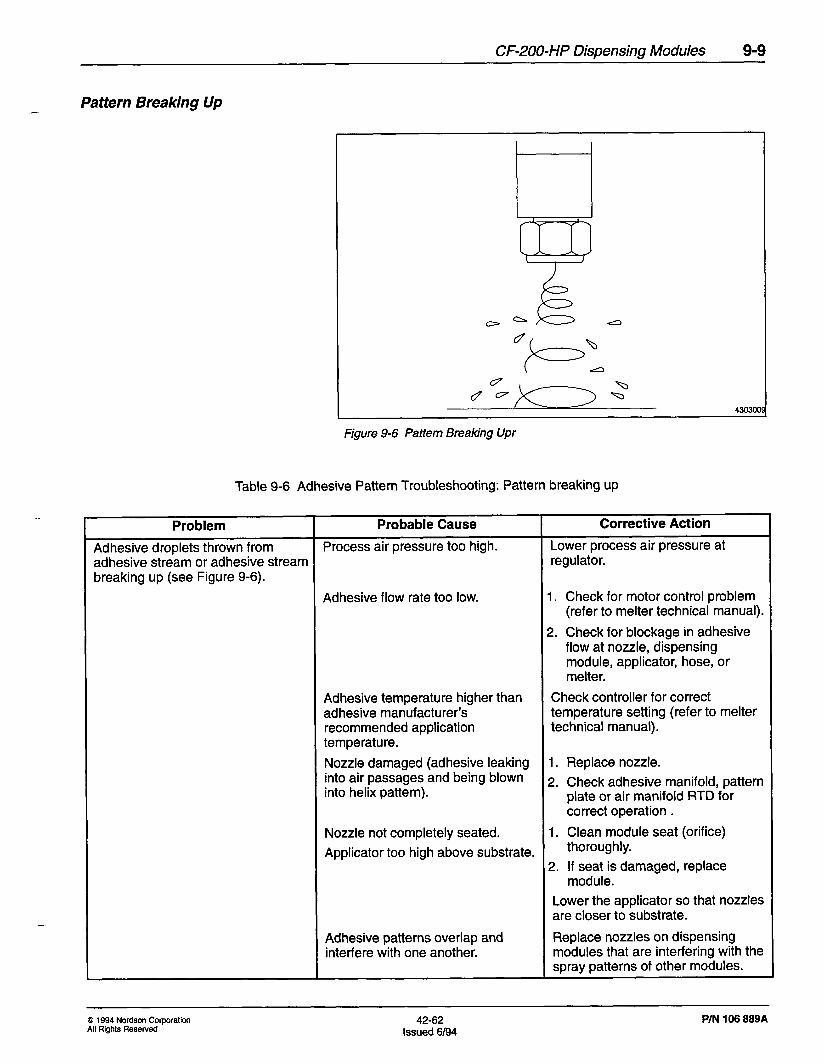
Pattern Breaking Up
4303oc
Figure 9-6 Pattern Breaking Upr
Table 9-6 Adhesive Pattern Troubleshooting: Pattern breaking up
Problem Probable Cause Corrective Action
Adhesive droplets thrown from Process air pressure too high. Lower process air pressure at adhesive stream or adhesive stream regulator. breaking up (see Figure 9-6).
Adhesive flow rate too low. 1. Check for motor control problem (refer to melter technical manual).
2. Check for blockage in adhesive flow at nozzle, dispensing module, applicator, hose, or melter.
Adhesive temperature higher than adhesive manufacturer’s recommended application temperature.
Check controller for correct temperature setting (refer to melter technical manual).
Nozzle damaged (adhesive leaking 1. Replace nozzle. into air passages and being blown into helix pattern).
2. Check adhesive manifold, pattern plate or air manifold RTD for correct operation .
Nozzle not completely seated. 1. Clean module seat (orifice)
Applicator too high above substrate. thoroughly.
2. If seat is damaged, replace module.
Lower the applicator so that nozzles are closer to substrate.
Adhesive patterns overlap and interfere with one another.
Replace nozzles on dispensing modules that are interfering with the spray patterns of other modules.
Q 1994 Nordson Corporation All Rights Reserved
42-62 Issued 6/94
P/N 106 889A

9-10 CF-200-HP Dispensing Modules
All Patterns Too Narrow
Figure 9-7 Al/patterns too narrowr
Table 9-7 Adhesive pattern troubleshooting: All patterns too narrow
Problem
All adhesive patterns too narrow (see Figure 9-7).
Probable Cause Corrective Action
Module operating air pressure less 1. Check operating air supply for than recommended. blockage.
2. Increase air pressure to recommended value.
Adhesive temperature lower than adhesive manufacturer’s recommended application temperature.
1. Verify that system ready light (located on controller) is on and adhesive is molten. If not, allow unit to reach operating temperature.
2. Check the circuit breaker and fuse for the melter and applicator electrical power. If necessary, reset the circuit breaker or replace the fuse.
3. Check the status of the controller and the temperature settings for the melter, hoses, and applicator (refer to controller documentation in melter technical manual). If the controller is off, turn it on. Adjust adhesive application device temperatures as required to maintain adhesive manufacturer’s recommended application temperature.
-
P/N 106 889A 42-62 Issued 6/94
Q 1994 No&on Corporation All Rights Reserved

CF-200-HP Dispensing Modules 9-11
Table 9-7 Adhesive pattern troubleshooting: All patterns too narrow (conk/.)
Problem Probable Cause
Adhesive temperature lower than adhesive manufacturer’s recommended application temperature.
Corrective Action
4. Disconnect and lock out electrical power. Check the resistance between each of the heater leads and ground. Resistance will be high if heater has failed with an open circuit. Resistance will be low if heater has failed with a short circuit.
5. Disconnect and lock out electrical power. Check resistance across heater leads. Replace heater if measured resistance is different from correct value. (Contact Nordson for correct heater specifications.)
6. Disconnect and lock out electrical power. Check resistance across temperature sensing device leads. Replace sensing device if measured resistance is different from correct value. (Contact Nordson for correct heater specifications.)
All CF-200-HP module microadjusters too tight.
Adhesive flow rate too high.
Readjust all modules as detailed in part 6 of this section.
1. Check pump speed setting at controller (refer to melter technical manual). Adjust pump speed if necessary.
Applicator pattern air pressure too low.
2. Check for motor control problem (refer to melter technical manual). Take action to correct any motor control problems found.
Check pattern air pressure at regulator. Recommended air pressure is 5-30 psi (0.034-0.207 MPa) for continuous applications and 5-50 psi (0.034-0.345 MPa) for intermittent applications. Increase air pressure if necessary.
Q 1994 Nordson Corporation All Rights Reserved
42-62 Issued 6/94
P/N 106 889A

9-12 CF-200-HP Dispensing Modules
Table 9-7 Adhesive pattern troubleshooting: All patterns too narrow (continued)
Problem Probable Cause Corrective Action
Applicator pattern air temperature too low.
Check temperature setting for pattern air at the controller. Raise temperature as required to maintain the pattern air at the adhesive manufacturer’s recommended application temperature (refer to the melter documentation).
P/N 106 889A 42-62 Issued 6/94
Q 1994 Nordson Corporation All Rights Resewed

CF-200-HP Dispensing Modules 9-13
All Patterns Too Wide
Figure 9-8 A// patterns too wide
Table 9-8 Adhesive pattern troubleshooting: All patterns too wide
Problem Probable Cause Corrective Action
All adhesive patterns too wide (see Adhesive temperature too high. I. Check melter, hose, and Figure 9-8). applicator temperature settings at
controller (refer to melter technical manual). Adjust temperature settings as required to maintain adhesive at manufacturer’s recommended application temperature.
2. Disconnect and lock out electrical power. Check resistance across temperature sensing device leads. Replace sensing device if measured resistance is different from correct value. (Contact Nordson for correct specifications.)
Module operating air pressure too high.
Adhesive flow rate too low.
Adjust operating air pressure to recommended value.
1. Check pump speed setting at controller (refer to melter technical manual). Adjust pump speed if necessary.
2. Check for motor control problem (refer to melter technical manual). Take action to correct any motor control problems found.
3. Use micro-adjust feature on module to ensure adhesive passage at bottom of module is open.
0 1994 No&on Corporation All Rights Reserved
42-62 Issued 6/94
P/N 106 889A

9-14 CF-200-HP Dispensing Modules
Table 9-8 Adhesive pattern troubleshooting: All patterns too wide (continued)
Problem Probable Cause
Applicator process air pressure too high.
Applicator process air temperature too high.
Nozzle adhesive opening too large
Corrective Action
Check air pressure at regulator. Recommended air pressure is 30-60 psi (0.21-0.42 MPa). Lower air pressure if necessary.
Check temperature setting for process air at the air heater. Lower temperature as required to maintain the process air at the adhesive manufacturer’s recommended application temperature (refer to the air heater documentation).
Select and install a nozzle with a smaller adhesive opening. (Refer to the nozzle selection tables in Con trolled Fiberiza tion spray nozzles in this section.)
P/N 106 889A 42-62 Issued 6/94
Q 1994 Nordson Corporation All Rights Reserved
CF-200-HP Dispensing Modules 945
5. Synchronizing the Modules
This material applies only to applications where a common solenoid is used to trigger two or more modules.
All modules are factory-set so that during a single cycle, the positions of the adhesive patterns on the substrate are synchronized. Consequently, there is no need to adjust dispensing module timing following installation. Also, continuous applications do not require dispensing module synchronization. (Continuous applications are applications in which the dispensing module is open for long periods, resulting in a long, continuous series of helix-shaped patterns of adhesive on the substrate.)
However, after dispensing modules have been in use for a period of time, it might be necessary to synchronize the adhesive pattern placement on the substrate for intermittent applications. (Intermittent applications are applications in which the module opens and closes frequently, resulting in numerous short helix-shaped adhesive patterns.)
A lock nut and load screw arrangement at the top of the dispensing module allows for slight adjustments to module timing. By loosening the lock nut and turning the load screw, the location on the substrate where the adhesive stream strikes can be moved forward or backward to align adhesive patterns on the substrate.
To synchronize the dispensing modules:
1. Trigger the modules to pump adhesive onto a moving substrate. Note the position of the patterns on the substrate.
2. If adjustment is needed, use a wrench to loosen the locking nut at the top of the chosen dispensing module and a screwdriver to adjust the loading screw (see Figure 9-9).
8 1994 Nordson Corporation All Rights Reserved
42-62 Issued 6/94
P/N 106 889A

9-16 CF-200-HP Dimensing Modules
4110334
Figure 9-9 Loosening the dispensing module locking nut
3. Perform one of the following adjustments as required by the placement of the adhesive patterns (see Figure 9-10):
a. To decrease the length of the adhesive pattern in the target area on the substrate, use a slotted screwdriver to turn the loading screw clockwise. This adjustment shortens the length at both ends of the patterns.
b. To increase the length of the adhesive pattern in the target area on the substrate, use a slotted screwdriver to turn the loading screw counterclockwise. This adjustment increases the length at both ends of the pattern.
P/N 106 889A 42-62 Q 1994 Nor&on Corporation
Issued 6194 All Rights Reserved

CF-200-HP Dispensing Modules 9-17
Figure 9- 10 Adjusting the CF-200 HP load screw
4. Repeat steps 1 through 3 for each dispensing module that requires synchronization.
_-
0 1994 Nordson Corporation All Rights Reserved
42-62 Issued 6/94
P/N 106 889A

9-18 CF-200-HP Dispensing Modules
6. Adjusting the Adhesive Pattern Thickness
Perform one or more of the following adjustments to change the thickness of the adhesive pattern:
Applicator
l Increase or decrease pump pressure.
l Increase or decrease pump speed.
l Install a nozzle with a larger or smaller adhesive opening (orifice).
l Use a slower or faster application line speed.
l Use a lower or higher viscosity hot melt adhesive.
-
P/N 106 889A 42-62 Issued 6/94
Q 1994 Nordson Corporation All Rights Reserved

Dispensing Module
CF-200-HP Dispensing Modules 9-19
Perform this procedure to change the thickness of the adhesive pattern for a specific module:
.
Note: The micro-adjuster is factory-set for maximum output.
1. Use a 7116 in. (11 mm) wrench to loosen the top lock nut.
2. With a screwdriver holding the load screw stationary, use a 5/8 in. (16 mm) wrench to turn the micro-adjusting nut clockwise to reduce pattern thickness. The micro-adjusting nut is the next hex fitting below the top lock nut. See Figure 9-11.
--
-
Figure 9- 1 I Setting the CF-200-HP micro-adjusting nut
8 1994 Nordson Corporation All Rights Resewed
42-62 Issued 6/94
P/N 106 889A
9-20 CF-200-HP Dispensing Modules
Dispensing Module (contd.) Note: Each quarter turn of the micro-adjust nut will reduce needle stroke by 0.001 in. (0.025 mm).
- Note: Take care not to turn the load screw (which will change gun synchronization).
CAUTION: Do not back the micro-adjusting nut out any further from its factory setting. Doing so will cause the gun to release hot melt material from the nozzle even though the gun is not triggered.
3. Tighten the top lock nut and lockwasher to 5 ft-lb (6.7 Nom), taking care not to change the load screw position.
4. Trigger the gun to check the pattern.
5. Repeat the procedure as needed to achieve the desired pattern thickness.
-
P/N 106 889A 42-62 Issued 6/94
Q 1994 Nordson Corporation All Rights Resewed

CF-200-HP Dispensing Modules 9-21
7. Disassembly and Repair The instructions for disassembling and rebuilding CF-200 dispensing modules are included in the dispensing module service kits. The dispensing module service kits are listed in CF-200 Standard Module Sewice Kits and Suggested Spare Parts list later in this section. Refer to the module rebuilding instructions included with the service kit to disassemble and rebuild a CF-200 dispensing module.
Removing and Replacing a Dispensing Module
Use the following procedure to remove and replace a CF-200 dispensing module:
1. Relieve the hydraulic pressure by following the procedure described in Relieving Hydraulic Pressure in Section 7.
2. Disconnect and lock out input power from the motor.
3. Wear safety gloves, safety goggles, and protective clothing.
4. Trigger the applicator to relieve any hydraulic pressure remaining in the applicator and dispensing module.
5. Shut off the supply of operating air to the applicator. This is the air supply that causes the dispensing module to open. (Each independent dispensing module or group of dispensing modules is supplied with operating air from a solenoid valve.)
6. Reduce the process air pressure to a small value to prevent adhesive from entering the air hole in the heated air manifold. (Process air is the air supplied to the module from the heated air manifold that creates the helix pattern of the adhesive.)
-
0 1994 Nordson Corporation All Rights Resewed
42-62 Issued 6/94
P/N 106 889A

9-22 CF-200-HP Dispensing Modules
Removing and Replacing a Dispensing Module (contd.)
7. Use a hex head wrench to remove the two socket head screws that attach the dispensing module to the applicator. (See Figure 9-12, Removing the Dispensing Module Socket Head Screws.)
4110337
Figure 9- 12 Removing the dispensing module socket head screws
8. Remove the dispensing module from the applicator.
9. Wipe any hot melt material from the pattern plate, especially around the air passages.
10. Remove and discard the three o-rings from the back of the dispensing module.
-
P/N 106 889A 42-62 Issued 6/94
Q 1994 No&on Corporation All Rights Resewed
CF-200-HP Dispensing Modules 9-23
- Removing and Replacing a 11. Coat the new o-rings with the lubricant provided in the dispensing
Dispensing Module (contd.) module service kit.
12. Install the three o-rings in the grooves in the back of the dispensing module body.
13. Apply anti-seize compound to the threads on the two socket-head screws.
14. Position the dispensing module on the pattern plate, aligning the holes for the socket-head screws on the module body to those on the adhesive manifold.
15. Replace and tighten the two socket-head screws that secure the dispensing module to applicator. Torque the screws to 30 lb-in (3.39 Nom).
Note: Do not over-tighten the screws. Over-tightening can cause the head of the screw to break off.
Note: For best results, torque the screws again after the applicator reaches operating temperature.
16. Restore the hot melt system to normal operation as described in the melter service manual.
0 1994 Nordson Corporation All Rights Reserved
42-62 Issued 6194
P/N 106 889A

9-24 CF-200-HP Dispensing Modules
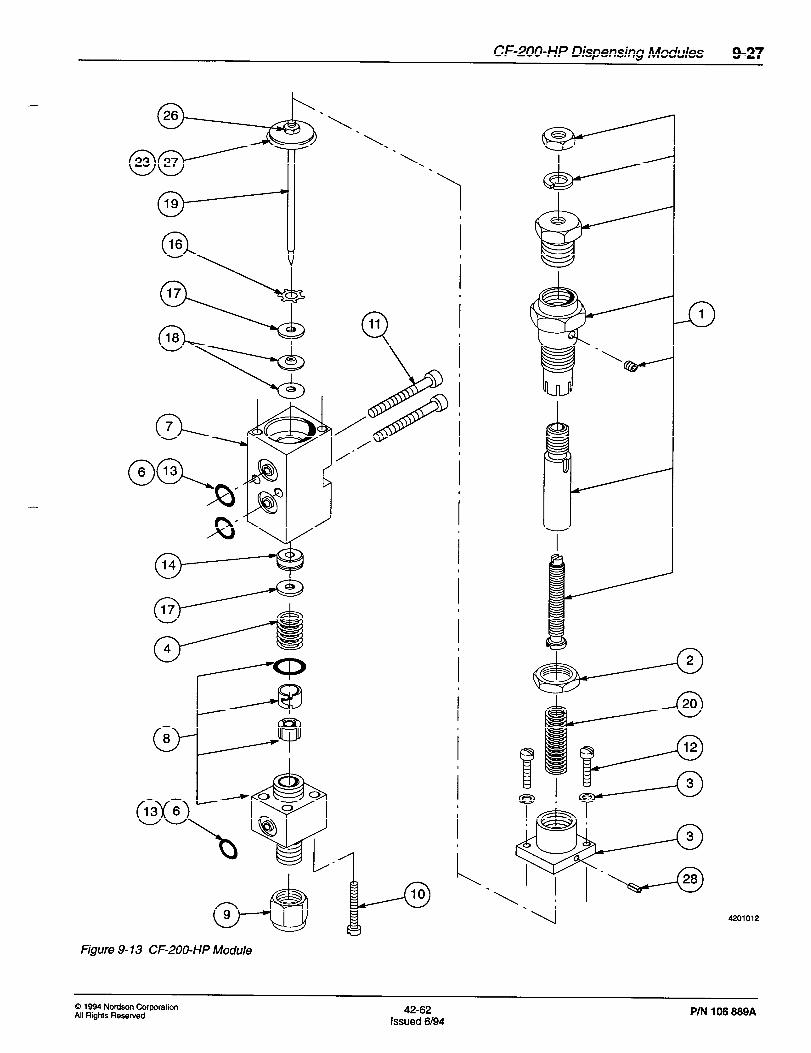
8. Dispensing Module Parts List and Reference Drawing
Table 9-9, CF-200-HP (High Performance) Dispensing Module Parts List, displays parts information for the CF-200 high performance dispensing module. The following information is included in the table:
l The item number column references the item to its location in the reference drawing (see Figure 9-13, CF-200-HP (High Performance) Module). A dash in this column means that the item is included in the list for reference only and is not part of the reference drawing.
l The part number column contains the Nordson part number for the item. A dash in this column means that the item is not available for sale by Nordson or that it is part of a subassembly that is available for sale.
l The description column contains the part’s name. The dimensions and physical properties may also be included in the part description. A part description that has one bullet (0) before it is part of the assembly above it.
l The quantity required column indicates the total number of that part used in the assembly. If the item is listed for reference only, “Ref appears in this column.
--
P/N 106 889A 42-62 Issued 6/94
Q 1994 Nor&on Corporation All Rights Reserved

CF-200-HP Dispensing Modules 9-25
0 1994 Nordson Corporation All Rights Resewed
42-62 Issued 6/94
P/N 106 889A
9-26 CF-200-HP Dispensing Modules
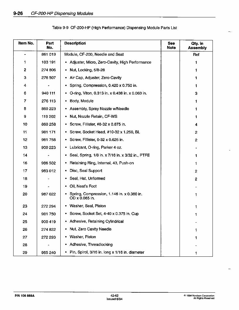
Table 9-9 CF-200-HP (High Performance) Dispensing Module Parts List
Item No. Part Descriptiori See Qty. in No. Note Assembly
861 019 Module, CF-200, Needle and Seat Ref
1 103 191 l Adjuster, Micro, Zero-Cavity, High Performance 1
2 274 806 l Nut, Locking, 5/8-28 1
3 276 507 l Air Cap, Adjuster, Zero-Cavity 1
4 l Spring, Compression, 0.420 x 0.750 in. 1
6 940 111 l O-ring, Viton, 0.313 in. x 0.438 in. x 0.063 in. 3
7 276 113 l Body, Module 1
8 860 223 l Assembly, Spray Nozzle w/Needle 1
9 119 202 l Nut, Nozzle Retain, CF-WS 1
10 860 258 l Screw, Fillister, #8-32 x 0.875 in. 4
11 981 171 l Screw, Socket Head, #lo-32 x 1.250, BL 2
12 981 758 l Screw, Fillister, 6-32 x 0.625 in. 2
13 900 223 l Lubricant, O-ring, Parker 4 oz.
14 l Seal, Spring, l/8 in. x 7116 in. x 3/32 in., PTFE 1
16 986 502 l Retaining Ring, Internal, 43, Push-on 1
17 983 012 l Disc, Seal Support 2
18 l Seal, Hat, Unformed 2
19 l Oil, Neat’s Foot
20 987 022 l Spring, Compression, 1.146 in. x 0.360 in. 1 OD x 0.065 in.
23 272 294 l Washer, Seal, Piston 1
24 981 750 l Screw, Socket Set, 4-40 x 0.375 in. Cup 1
25 900 419 l Adhesive, Retaining Cylindrical
26 274 822 l Nut, Zero Cavity Needle 1
27 272 293 l Washer, Piston 1
28 l Adhesive, Threadlocking
29 985 240 l Pin, Spirol, 3/l 6 in. long x l/16 in. diameter 1
-
P/N 106 889A 42-62 0 1994 Nordson Corporation
Issued 6/94 All Rights Reserved
CF-200-HP Dispensing Modules 9-27
-
I
d 9
Figure 9-13 CF-200-HP Module
4201012
Q 1994 No&on Corporation All Rights Reserved
42-62 Issued 6/94
P/N 106 889A

9-28 CF-200-HP Dispensing Modules
9. Dispensing Module Service Parts
The following table contains the CF-200 high performance dispensing module service kits and recommended spare parts.
Table 9-10 CF-200-HP Module Service Kits and Spare Parts
Item No. Part Description See Qty. in No. Note Assembly
901 915 Nozzle Cleaning Kit
860 892 H-200 Seal Rebuild Kit, Single Module (w/Needle and Piston)
147 473
940 111
CF-200 Seal Support Kit
O-ring, Viton, 0.313 in. x 0.438 in. x 0.063 in. (for Sealing Module Air and Adhesive Supplies)
940 031 O-ring, Viton, 0.087 in. x 0.127 in. x 0.020 in. (for Cap and Unibody Nozzles)
133 663 O-ring, Kit, Viton, Spray Cap, 100 (for Cap and Unibody Nozzles)
133 664 O-ring, Kit, Viton, Spray Cap, 25 (for Cap and Unibody Nozzles)
133 665 O-ring, Kit, Viton, Spray Cap, 10 (for Cap and Unibody Nozzles)
119 202
981 171
Nut, Nozzle Retaining, CF-WS
Screw, Socket Head, #lo-32 x 1.250 in., BL (for Attaching Module to Applicator)
P/N 106 889A 42-62 issued 6/94
Q 1994 Nordson Corporation All Rights Reserved

CF-200-HP Dispensing Modules 9-29
IO. Controlled Fiberization Spray Nozzles
Three types of Controlled Fiberization spray nozzles are available for CF-200 modules:
l disk
l cap
l unibody
Disk spray nozzles are held on the dispensing module by a retaining nut. A disk nozzle is protected from damage by being recessed inside the retaining nut when attached to the module. Refer to Table 9-11 for information about disk nozzles.
Cap and unibody spray nozzles are designed with the disk and retaining nut as a single assembly. This design allows for ease of cleaning because there are no recessed surfaces as with the disk spray nozzles. Refer to Table 9-l 2 for information about cap nozzles and to Table 9-13 for information about unibody nozzles.
Table 9-11 Disk Nozzles
Orif ice Diameter
0.008
Rotation Angle
cw Standard
P/N
104 100
I 0.010 I cw I Standard I 104 101 I
0.012 cw Standard 860 548
0.012 cw Wide angle 109 705
I 0.012 I ccw I Standard I 101 225 I I 0.014 I cw I Standard I 860 574 I I 0.016 7 1 Standard I 860 575 I
I 0.018 I cw I Standard I 860 226 I I 0.018 I ccw I Standard I 860 577 I I 0.018 I cw I Wide angle I 131 340 I I 0.020 I cw I Standard I 860 435 I I 0.025 I cw I Standard I 100 728 I I 0.030 I cw I Standard I 810 381 I I 0.030 I ccw I Standard I 149 380 I I 0.030 I cw I Wide angle I 133 810 I
0.040 cw Standard 810 382
0.050 cw Standard 810 300
--.
0 1994 Nordson Corporation All Rights Reserved
42-62 Issued 6/94
P/N 106 889A

9-30 CF-200-HP Dispensing Modules
Table 9-12 Cap Nozzles
Table 9-13 Unibody Nozzles -
pm 106 aa9A 42-62 Issued 6/94
0 1994 Nordson Corporation All Rights Reserved


