CFD simulation and analysis for free surface computations around fixed ‘DTMB 5415’ ship model Project By: Gurav Harshada A. B8290831 Kadam Suyog S. B8290845 Thakur Bhagwan R. B8290903 1 Guided by: Prof. N. K. Kharate.
Transcript
1
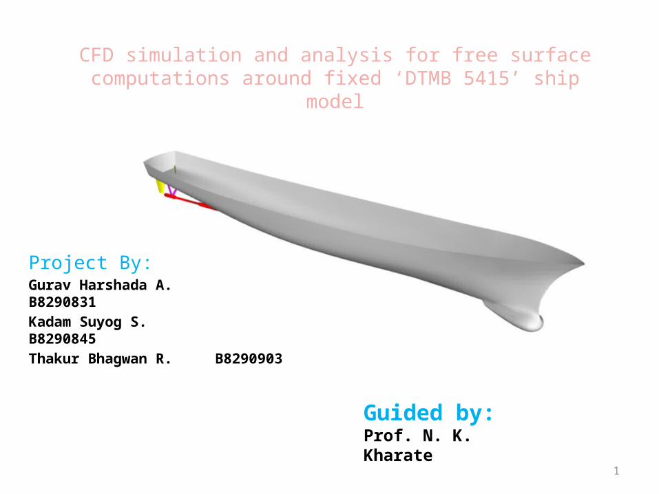
CFD simulation and analysis for free surface computations around fixed ‘DTMB 5415’ ship model
Project By:Gurav Harshada A. B8290831
Kadam Suyog S. B8290845
Thakur Bhagwan R. B8290903
Guided by:Prof. N. K. Kharate.
2
Content Introduction
Literature review
Problem definition and objectives
Methodology
Modeling
Meshing
Boundary conditions
post processing
Introduction to test case
Results
Advantages and Limitations of CFD
Conclusion
References
3
INTRODUCTION
Computational fluid dynamics (CFD) is the science of predicting fluid behavior and related phenomena by solving the mathematical equations using a numerical process.
This analysis presents results of the computations performed in the ETSIN for US navy combatant DTMB 5415 ship with the RANSE free surface commercial solver CFX.
In this process we are using ANSYS ICEM for modeling and grid generation and ANSYS CFX for pre processing, solver and post processing.
4
Literature review
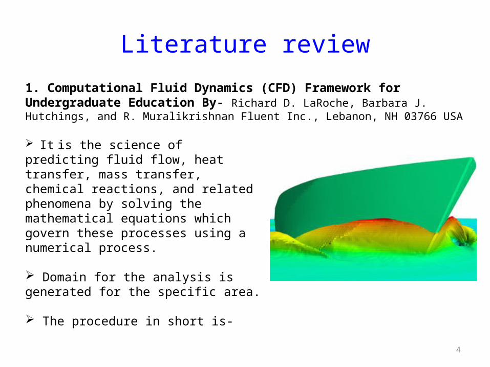
1. Computational Fluid Dynamics (CFD) Framework for Undergraduate Education By- Richard D. LaRoche, Barbara J. Hutchings, and R. Muralikrishnan Fluent Inc., Lebanon, NH 03766 USA
It is the science of predicting fluid flow, heat transfer, mass transfer, chemical reactions, and related phenomena by solving the mathematical equations which govern these processes using a numerical process.
Domain for the analysis is generated for the specific area.
The procedure in short is-
5
1. Modeling: Design of computer simulated model using points, curves,
surfaces etc.
2. Meshing: Discretization of model using different types.
3. Boundary conditions: Input Data
4. Computation: The set of algebraic equations are solved numerically to
calculate the quantities of interest on each cell.
5. Post processing: Review of result in graphical and analytical ways.
6
2. CFD APPLICATIONS IN SHIP DESIGN OPTIMIZATIONBy- Khairul Hassan and Maurice F. White
Multiphase model
7
meshing Meshing is mainly divided into two types- Structured And Unstructured.
The structured meshing is again then classified into following sub-types-
The combination of structured and unstructured can also be done in the complex geometry for getting the fine meshing as well as better results. That is known as ‘Hybrid Mesh’.
The mesh quality can also be determined in ICEM. It should be positive. The quality is given in determinant form.
For better mesh quality, the angle in hexa mesh should be greater that 18 deg; while for terta, it should be greater than 14 deg.
• Tetrahedron
• Triangle
• Quadrilateral• Pyramid
• Prism or wedge• Hexahedron
• Arbitrary polyhedron
8
Mesh Quality Check
• 1 Would indicate a perfectly regular mesh element, 0 would indicate an element degenerate in one or more edges, and negative values would indicate inverted elements.
9
3. RANSE with free surface computations around fixed DTMB 5415
model and other Baliño’s fishing vessels
-Martín Priego Wood1, Leo M. González1, Jorge Izquierdo1, Adrián Sarasquete2 and Luis Pérez Rojas1
The momentum and pressure are simultaneously satisfied using a coupled
solution system.
This method predict the fluid velocity distribution by solving the Navier-
Stokes equations around the ship.
Initially unstructured meshes were used for the first results
Due to the poor results obtained with unstructured meshes an alternative
‘structural’ meshing was used.
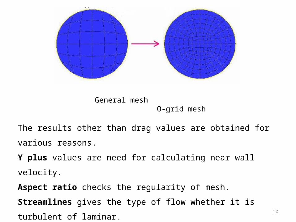
The structured mesh is based on a O-grid block distribution.
10
The results other than drag values are obtained for various reasons.
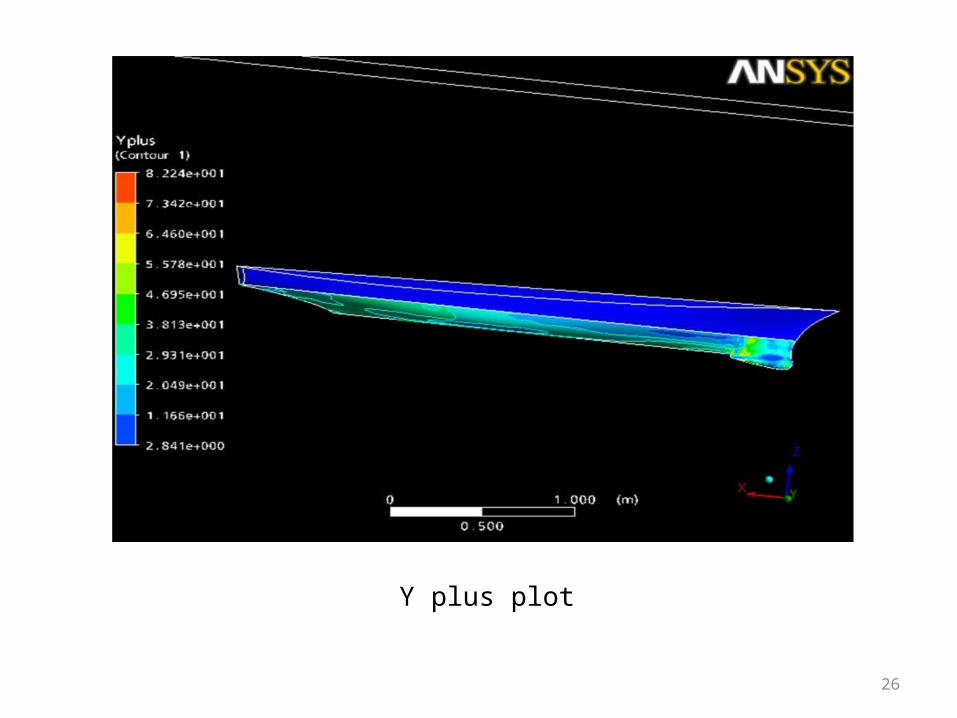
Y plus values are need for calculating near wall velocity.
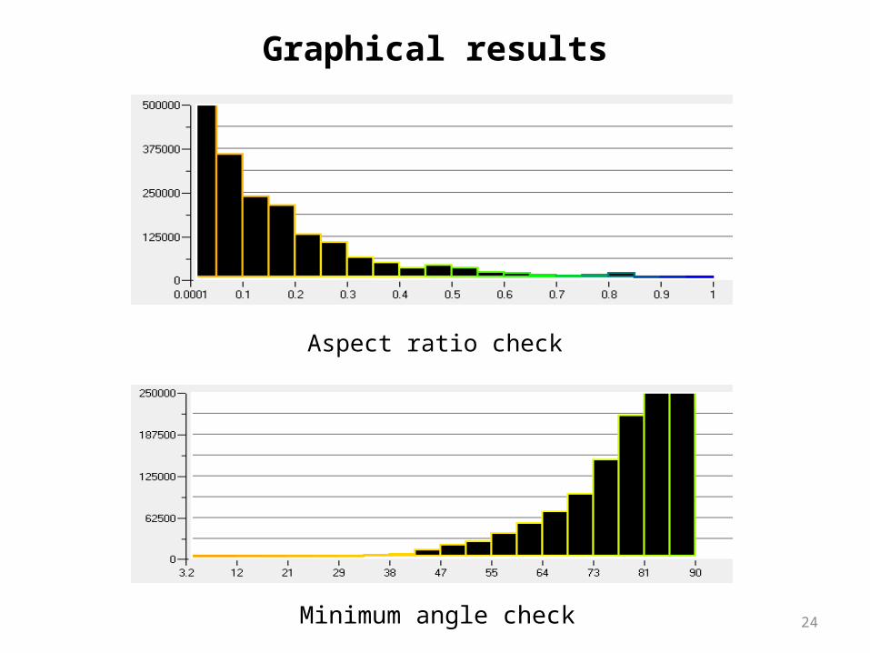
Aspect ratio checks the regularity of mesh.
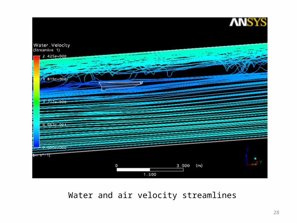
Streamlines gives the type of flow whether it is turbulent of laminar.
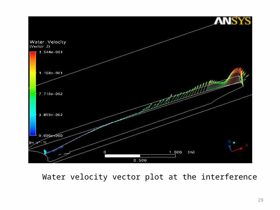
Vector plots are used to find out magnitude and direction vector quantities.
Etc.
General mesh O-grid mesh
11
Problem Definition
This project aims to find out performance of ship by calculating drag force and
drag coefficient using better mesh quality. This is done by using ANSYS ICEM
and CFX software.
Objectives
Performance of the model deals with the aerodynamic efficiency. Ship faces water
and air simultaneously which opposes the motion. The resistance force caused by
fluid is drag force which is calculated in this analysis.
12
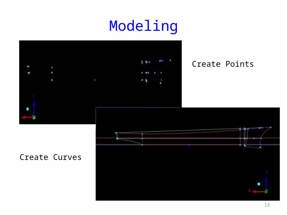
Modeling
Create Points
Create Curves
13
Create surfaces
Create block
14
The total boundary length is 1000m, breadth is 245 m, and the height is also 245m and the ship position at the centre of the bottom surface.
Mesh region
15
Hybrid mesh : mesh with one of the following :
O-grid index is also defined
Mesh size :
nodes = 1929333
quads = 163716
hexas = 1856472
Total elements = 2020907
Mesh Details
16
Final Meshed Model
17
Boundary Conditions
Top Inlet Outlet Bottom Symmetry Side wall Ship bottom Ship top Ship top 1
DRAG COEFFICIENT calculations
ρ = 1000 kg/m^2SDWL = 4.861 m^2,U = 2.097 m/s
CT = 4.368 __ computational
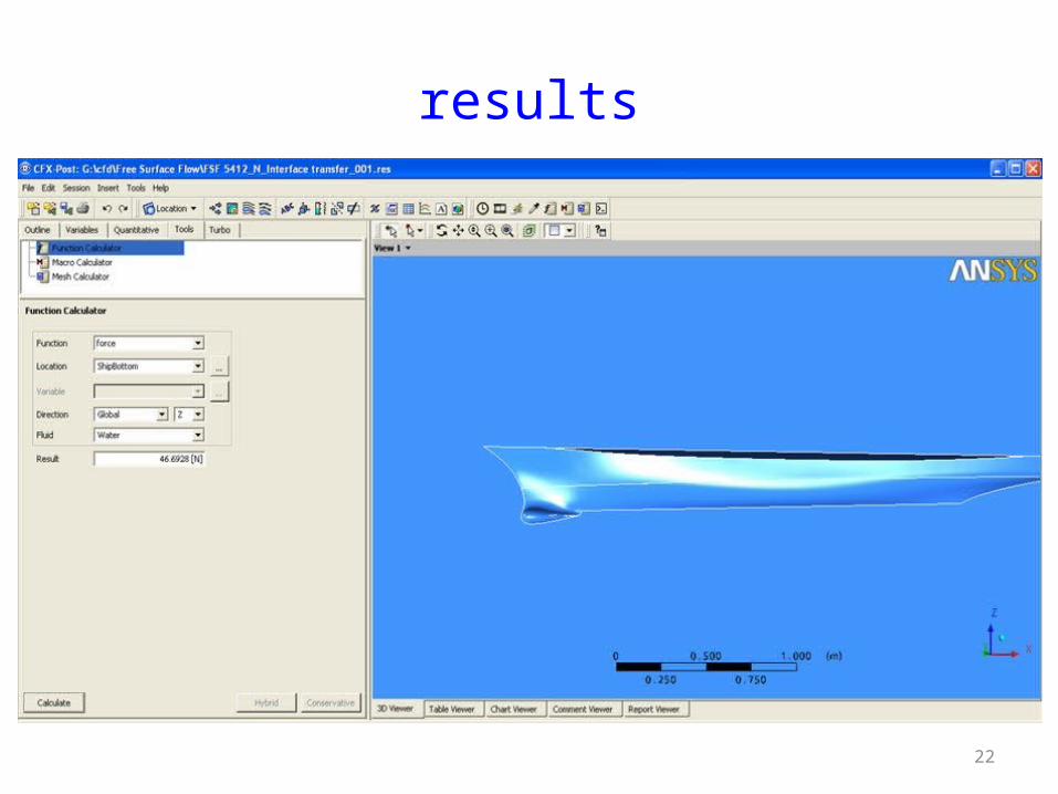
Resistance = 46.6928 N ____ computational
19
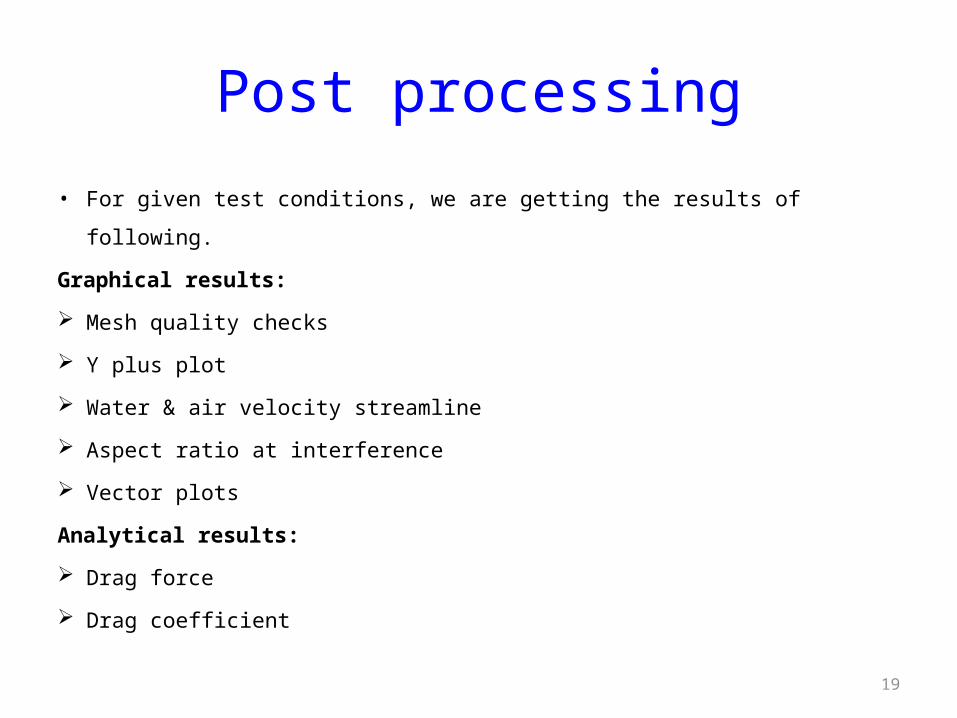
Post processing
• For given test conditions, we are getting the results of following.
Graphical results:
Mesh quality checks
Y plus plot
Water & air velocity streamline
Aspect ratio at interference
Vector plots
Analytical results:
Drag force
Drag coefficient
20
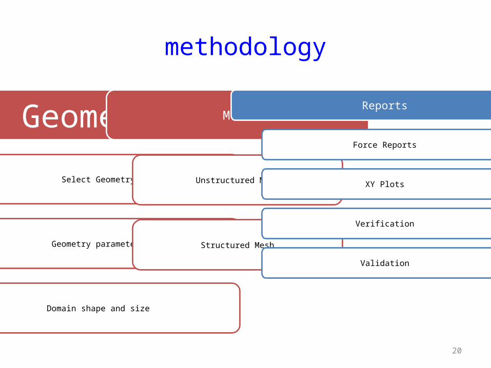
methodology
Geometry
Select Geometry
Geometry parameters
Domain shape and size
Mesh
Unstructured Mesh
Structured Mesh
Reports
Force Reports
XY Plots
Verification
Validation
21
Introduction to test case
ETSIN
Forward 0.75L
Aft 1.75L
Side 1.75L
Below 1.25L
Dimensions considered for the Combatant DTMB 5415 control volume.
Parameter Experimental data
Length (m) 5.72
Beam (m) 0.76
Draft (m) 0.248
Wetted surface area (m^2) 4.486
Density (kg/m^3) 999
Comparison between experimental and computational values.
22
results
23
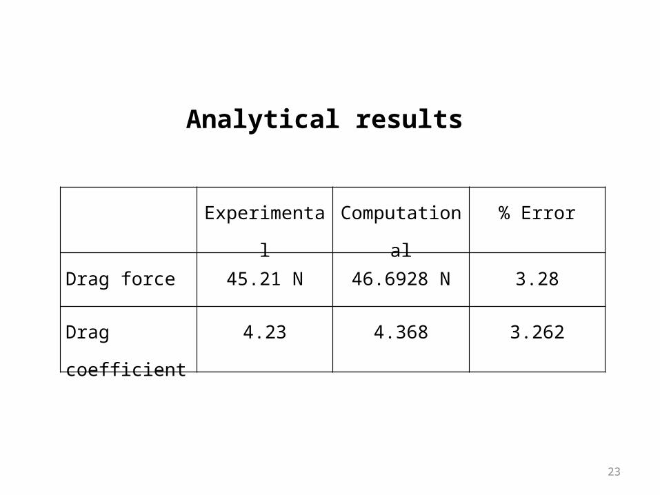
Analytical results
Experimental Computational % Error
Drag force 45.21 N 46.6928 N 3.28
Drag coefficient 4.23 4.368 3.262
24
Graphical results
Aspect ratio check
Minimum angle check
25
Mesh quality check
26
Y plus plot
27
Aspect ratio at interference
28
Water and air velocity streamlines
29
Water velocity vector plot at the interference
Advantages of CFD Relatively low cost. Speed. Ability to simulate real conditions. Ability to simulate ideal conditions.
30
LIMITATIONS OF CFD
Boundary conditions.
Numerical errors.
Human errors.
31
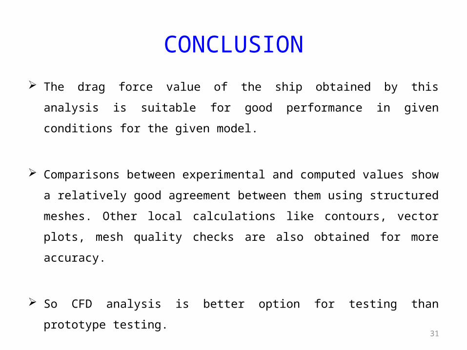
CONCLUSION
The drag force value of the ship obtained by this analysis is suitable for
good performance in given conditions for the given model.
Comparisons between experimental and computed values show a relatively
good agreement between them using structured meshes. Other local
calculations like contours, vector plots, mesh quality checks are also
obtained for more accuracy.
So CFD analysis is better option for testing than prototype testing.
32
Further using this technique we can also obtain, Fuel economy, Wake coefficients, Wave elevations, Wave profile at required sections, Balancing, stability and effect of waves on ship and stock on the ship, Heating and cooling of engine, Also results for propeller similar to ship hull.
Future scope
33
References• Martín Priego Wood, Leo M. González, RANSE with free surface computations around fixed DTMB 5415
model and other Baliño’s fishing vessels. 9th International Conference on Numerical Ship Hydrodynamics Michigan, USA, 5-8 August 2007.
• Metin Ozen, Ph.D., CFD Research Corporation Ashok Das, Ph.D., Applied Materials Kim Parnell, Ph.D.,
Parnell Engineering and Consulting. CFD Fundamentals and Applications.
• Tao Xing and Fred Stern, IIHR— Hydro science & Engineering, C. Maxwell Stanley Hydraulics
Laboratory, The University of Iowa.
• Wenbin Song, Andy Keane, Hakki Eres, Graeme Pound, and Simon Cox. Two Dimensional Airfoil Optimization Using CFD in a Grid Computing Environment.
• Leo Lazauskas, Cyberiad, Resistance and Squat of Surface Combatant DTMB Model 5415: Experiments
• C. Böhm, R&D Centre Univ. Appl. Sciences Kiel, Yacht Research Unit, Germany K. Graf, Univ. Applied Sciences Kiel, Germany Validation Of Ranse Simulations Of A Fully Appended Acc V5 Design Using Towing Tank Data.
• Gianpiero Lavini1, Lorenzo Pedone1, Davide Harpo Genuzio Application of fully viscous CFD codes in the design of non propellers for passenger vessels.
• B. Godderidge1 A.B. Phillips, S. Lewis, S.R. Turnock, D.A. Hudson, and M. Tan. Fluid-Structure Interactions Research Group, Froude Building, School of Engineering Sciences, University of Southampton, SO17 1BJ, UK. The simulation of free surface flows with Computational Fluid Dynamics.
• Khairul Hassan, Maurice F. White. CFD Applications in Ship Design Optimization.