14


CH.100
River WindrushEast Branch
Swale
River WindrushWest Branch
A receiving ditch is to be provided toassist in conveying flood flows.
CH.410
Cogges Link Road
CH.190
CH.220
CH.250
CH.310
A
ACH.280
FP2 Storage Area
Spill Area
1000mm wide weir (invert level78.000m OD) set 100mm aboveculvert invert.
1 No. 1200mm dia piped culvertproviding linkage to flood storagearea through CLR embankment.
A
A
B
B
C
C
Min headwall width= 2600 mm
Steve HowellDeputy Director ofEnvironment & EconomyOxfordshire County CouncilSpeedwell HouseSpeedwell StreetOxfordOX1 1NETel: (01865) 815700Fax: (01865) 241577
Reproduced from the Ordnance Survey mapping with the permission of the Controller ofHer Majesty's Stationery Office © Crown Copyright. Unauthorised reproductioninfringes Crown Copyright, and may lead to prosecution or civil proceedings.Oxfordshire County Council Licence No LA076805
P:\4
. Im
prov
emen
t Sch
emes
\Sch
emes
\S-0
0033
8 C
ogge
s Li
nk R
oad\
Dra
win
gs\W
orki
ng\fl
ood
risk
asse
ssm
ent\F
lood
Com
pens
atio
n re
v C
.dw
g
A4095 WITNEY:COGGES LINK ROAD
FP2 FLOOD STORAGE AREADESIGN DETAILS
FOR INFORMATION
1:1000MG
14/09/11
AG
14/09/11
MJCO
14/09/11
HQ22135
CLR/FRA/001 C
CLR/FRA/001 C
0 14/09/11 FIRST ISSUE MG AG MJCO
A 3/10/11 WEIR ADDED RECEIVING DITCH AMENDED AG NWD MJCo
B 26/10/11 SPILL LEVEL ADDED, NOTE ADDED AG NWD MJCo
C 3/11/11 DRAWING UPDATED CULVERT GRILL DELETED-LANDSCAPE CHANGES AG MG MJCo
KEY:FP2 Flood storage area. Existingground level to be lowered by 0.2m.Area = 6252m².
Spill Area. The raised groundbetween the river and floodplain willbe removed, proposed level of thespillway and footway will be 78.70mat this location .
Existing ground level to be loweredto match levels in storage area FP2to assist in conveying flows throughthe culvert.
Proposed Realignment of existingfootpath.
NOTES:1.Transition slopes between surrounding existing
ground level and proposed storage levels to be1:10.
2.For details of cross sections through the floodstorage area see drawing no. CLR/FRA/003 &004.
3.For details of long section through culverts seedrawing no. CLR/FRA/07.
4.For details of landscape treatment of FP2 storagearea see drawing no. HQ22135/DD/4470 (Figure15 of the LEMS).
5. Minimum level of footpath running adjacent toFP2 area between the west bridge and theentrance to the Country Park will be 78.900MAOD to prevent channel cross flow see drg.no.HQ22135/FRA/008 for cross sections of footwayto the west of the FP2 area.
6. For details of the River Windrush (West Branch)channel diversion please see drawing numberB0800100/DD/4457( Figure 5 of the LEMS).
7.Where levels require lowering the turf will beremoved carefully and temporarily stored. Soilswill be removed to a depth of 200mm and the turfreinstated.
8. Culvert headwall will be constructed inaccordance with Environment Agency StandardDetail SD13.

Eastern Pond Complex
FP6 Storage Area
Swale
Swale
Outfall structure (invert level 77.4mOD) will incorporate a flat V weir1000mm wide, with a 300mm risefrom the center to each side of theweir.
Existing ditch to be enhanced to provideimproved drainage of the lowered area.
Swale
2 No. 1200mm dia piped culvertsproviding linkage to flood storagearea through CLR embankment.
CH.410
CH.440
CH.470
CH.500
CH.530 CH.560
Cogges Link Road
River W
idrush (East Branch)
CH.310
Swale
B
B
CH.280
Min headwall width= 4600 mm
Steve HowellDeputy Director ofEnvironment & EconomyOxfordshire County CouncilSpeedwell HouseSpeedwell StreetOxfordOX1 1NETel: (01865) 815700Fax: (01865) 241577
Reproduced from the Ordnance Survey mapping with the permission of the Controller ofHer Majesty's Stationery Office © Crown Copyright. Unauthorised reproductioninfringes Crown Copyright, and may lead to prosecution or civil proceedings.Oxfordshire County Council Licence No LA076805
P:\4
. Im
prov
emen
t Sch
emes
\Sch
emes
\S-0
0033
8 C
ogge
s Li
nk R
oad\
Dra
win
gs\W
orki
ng\fl
ood
risk
asse
ssm
ent\F
lood
Com
pens
atio
n re
v C
.dw
g
A4095 WITNEYCOGGES LINK ROAD
FP6 FLOOD STORAGE AREADESIGN DETAILS
FOR INFORMATION
1:1000MG
14/09/11
AG
14/09/11
MJCO
14/09/11
HQ22135
CLR/FRA/002 B
CLR/FRA/002 B
0 14/09/11 FIRST ISSUE MG AG MJCo
A 3/10/11 OUTFALL AMENDED - NOTES ADDED AG NWD MJCo
B 3/11/11 CULVERT GRILL DELETED, FOOTBRIDGE ADDED AG NWD MJCo
KEY:FP6 Flood storage area. Existingground level to be lowered by 0.7m atthe upstream end (nearest to the CLR),and by 0.3M at the downstream end. Inpractice there will be a slope (ofapproximately 1 in 1000) across the areafor effective drainage. Area = 21089m2
NOTES:
1. Transition slopes between surroundingexisting ground level and proposed storagelevels to be 1:10.
2. For details of cross sections through the floodstorage area see drawing no. CLR/FRA/005 &006.
3. For details of long section through culvertssee drawing no. CLR/FRA/07.
4. The level at the centre of the weir is the samelevel as the downstream end of the loweredFP6 area.
5. At its downstream end, the FP6 area willdischarge into an existing ditch which leads tothe outlet flat-V weir. A flapped 250mmdiameter orifice at the outlet of the ditchbeneath the flat-V weir will be provided forland drainage purposes. For details of the FP6outfall see drawing no. HQ22135/CLR/EA/15.
6. Culvert headwall will be constructed in accordance with Environment Agency Standard Detail SD13.

Chainage = 190.000
78.5
20
80.2
5480
.330
80.4
54
83.4
7983
.529
83.4
5583
.421
83.5
9383
.402
78.5
44
-29.
208
-24.
048
-22.
985
-20.
329
-7.6
50-6
.650
-3.6
750.
000
3.67
57.
483
26.9
17
78.6
7578
.691
78.7
05
78.6
0678
.660
78.8
8878
.506
78.2
0977
.869
77.7
1577
.555
77.5
4077
.540
77.6
0577
.885
78.8
5478
.825
78.7
84
78.5
36
78.4
74
78.4
13
78.3
38
78.2
84
78.3
15
78.3
4378
.557
78.5
4078
.523
78.5
2078
.404
78.3
8378
.374
78.4
5278
.501
78.5
0178
.472
78.2
6778
.546
78.5
6078
.556
78.5
53
78.5
4178
.539
78.5
1278
.511
78.5
0078
.500
78.5
00
Chainage = 220.000
78.5
47
82.1
2982
.198
82.2
74
83.6
7383
.723
83.6
4983
.652
83.7
7983
.731
79.2
30
78.1
3078
.130
79.2
3079
.230
78.4
57
-27.
866
-17.
120
-16.
087
-14.
020
-7.6
50-6
.650
-3.6
75-0
.000
3.65
07.
150
24.9
65
29.3
6633
.415
38.7
8740
.008
43.7
82
79.0
6778
.500
78.0
0077
.520
77.5
2077
.520
77.5
2077
.520
77.5
2077
.235
78.9
1579
.006
78.7
68
78.5
56
78.4
83
78.4
75
78.3
66
78.3
3878
.340
78.3
03
78.3
08
78.2
76
78.5
1178
.560
78.5
6078
.556
78.5
6078
.560
78.5
60
78.5
47
78.5
1478
.510
78.5
0078
.474
78.4
60
78.4
8778
.479
78.4
60
78.4
48
Chainage = 250.000
78.5
47
83.1
9383
.265
83.3
8683
.772
83.8
2283
.747
83.7
5083
.878
83.7
46
80.3
37
-26.
617
-12.
896
-11.
846
-9.7
46-7
.650
-6.6
50-3
.675
-0.0
003.
650
12.9
08
50.0
00
78.5
7877
.520
77.5
2077
.520
77.5
2077
.591
78.5
4577
.609
78.1
7278
.836
78.8
8578
.912
78.8
69
78.6
83
78.6
60
78.5
63
78.3
7178
.365
78.3
73
78.3
5778
.349
78.2
6578
.520
78.5
25
78.5
40
78.5
4078
.532
78.5
20
78.5
0378
.497
78.4
8978
.485
78.4
80
78.4
6278
.460
78.4
57
Level Datum =75.000
Design LEVELS
Design OFFSET
Level Datum =75.000
Design LEVELS
Design OFFSET
Level Datum =75.000
Design LEVELS
Design OFFSET
78.3
1178
.103
78.0
89
78.2
47
78.7
00
78.7
00
-34.
808
-36.
808
-40.
000
-60.
000
-80.
000
-90.
197
77.0
48
78.3
0978
.109
78.1
10
78.1
95
78.3
4278
.351
78.7
00
77.0
48-3
0.34
8
-35.
012
-37.
012
-40.
000
-60.
000
-80.
000
-80.
982
-100
.934
-32.
170
76.8
2276
.822
78.3
3878
.148
78.1
60
78.1
68
78.3
75
78.4
6778
.674
-29.
736
-31.
760
-33.
816
-35.
816
-40.
000
-60.
000
-80.
000
-90.
117
-92.
117
Cross Sections through FP2 flood storage area - CH190 - 250Scale Horizontal 1:100 Scale vertical 1:500
Existing GroundLEVELS
Existing GroundLEVELS
Existing GroundLEVELS
78.7
00-8
2.00
0
78.7
00-9
0.90
078
.700
-92.
900
Steve HowellDeputy Director ofEnvironment & EconomyOxfordshire County CouncilSpeedwell HouseSpeedwell StreetOxfordOX1 1NETel: (01865) 815700Fax: (01865) 241577
Reproduced from the Ordnance Survey mapping with the permission of the Controller ofHer Majesty's Stationery Office © Crown Copyright. Unauthorised reproductioninfringes Crown Copyright, and may lead to prosecution or civil proceedings.Oxfordshire County Council Licence No LA076805
C:\D
ocum
ents
and
Set
tings
\mat
thew
.gar
dner
\Des
ktop
\Dra
win
gs\F
lood
Sto
rage
FP
2 S
ectio
ns.d
wg
A4095 WITNEY:COGGES LINK ROAD
CROSS SECTIONS THROUGH FP2 FLOOD STORAGE AREA
SHEET 1 OF 2
FOR INFORMATION
AS STATEDMG
14/09/12
AG
14/09/11
MJCO
14/09/11
HQ22135
CLR/FRA/003 A
CLR/FRA/003 A
0 14/09/11 FIRST ISSUE MG AG MJCO
A 23/11/11 FOOTPATH ADDED AG MG MJCo
KEY:
Existing ground level
Proposed ground level
NOTES:
1. Cross sections are drawn through themainline string of the Cogges Link Road.Section lines can be located on drawingno. CLR/FRA/001.
Footpath
Footpath

Chainage = 280.000
78.5
42
81.3
9481
.466
83.7
3883
.788
83.7
1383
.716
83.9
6983
.791
79.2
4379
.230
79.2
3079
.230
78.4
80
-29.
103
-19.
721
-17.
669
-7.6
50-6
.650
-3.6
500.
000
3.65
07.
221
25.4
1327
.020
33.8
8435
.796
39.4
34
78.5
0077
.509
77.5
0077
.500
77.5
0077
.329
78.2
3978
.740
78.8
0378
.847
78.7
81
78.6
3378
.517
78.5
09
78.5
09
78.4
91
78.4
55
78.4
28
78.3
93
78.3
72
78.3
5178
.338
78.4
8278
.520
78.5
2078
.520
78.5
20
78.5
3678
.540
78.5
40
78.5
4078
.514
78.5
0378
.491
78.4
8278
.467
78.4
75
Chainage = 310.000
78.6
1479
.419
79.5
0979
.299
79.2
5178
.512
78.8
1783
.658
83.4
5883
.549
83.5
5683
.493
78.5
39
-29.
117
-26.
703
-23.
579
-20.
460
-19.
283
-14.
903
-8.5
46-6
.650
-3.6
500.
000
3.65
07.
436
10.6
61
78.7
1978
.849
78.5
0078
.000
77.4
8077
.480
77.4
8077
.488
77.2
7278
.728
78.7
69
78.5
5678
.508
78.4
48
78.4
8978
.497
78.4
93
78.4
43
78.2
8078
.295
78.3
0478
.331
78.4
56
78.4
72
78.5
8378
.554
78.6
1878
.540
78.5
33
78.5
4078
.546
78.5
7478
.574
78.5
1778
.509
78.5
0478
.500
78.5
0078
.500
78.4
7778
.481
Level Datum =75.000
Design LEVELS
Design OFFSET
Level Datum =75.000
Design LEVELS
Design OFFSET
78.3
5478
.163
78.1
82
78.2
51
78.3
09
78.3
1778
.573
-32.
103
-34.
103
-40.
000
-60.
000
-80.
000
-90.
103
-92.
103
78.3
7278
.317
78.1
39
78.2
76
78.2
60
78.2
5978
.475
-40.
000
-60.
000
-80.
000
-42.
518
-44.
518
-85.
317
-87.
317
Cross Sections through FP2 flood storage area - CH280 - 310Scale Horizontal 1:100 Scale vertical 1:500
Existing GroundLEVELS
Existing GroundLEVELS
Steve HowellDeputy Director ofEnvironment & EconomyOxfordshire County CouncilSpeedwell HouseSpeedwell StreetOxfordOX1 1NETel: (01865) 815700Fax: (01865) 241577
Reproduced from the Ordnance Survey mapping with the permission of the Controller ofHer Majesty's Stationery Office © Crown Copyright. Unauthorised reproductioninfringes Crown Copyright, and may lead to prosecution or civil proceedings.Oxfordshire County Council Licence No LA076805
C:\D
ocum
ents
and
Set
tings
\mat
thew
.gar
dner
\Des
ktop
\Dra
win
gs\F
lood
Sto
rage
FP
2 S
ectio
ns.d
wg
A4095 WITNEY:COGGES LINK ROAD
CROSS SECTIONS THROUGHFP2 FLOOD STORAGE AREA
SHEET 2 OF 2
FOR INFORMATION
AS STATEDMG
14/09/11
AG
14/09/11
MJCO
14/09/11
HQ22135
CLR/FRA/004 0
CLR/FRA/004 0
0 14/09/11 FIRST ISSUE MG AG MJCO
KEY:
Existing ground level
Proposed ground level
NOTES:
1. Cross sections are drawn through themainline string of the Cogges Link Road.Section lines can be located on drawingno. CLR/FRA/002.
2. Section at CH 310 crosses through thebridge deck of the Cogges Link Road.

Level Datum =75.000
Chainage = 470.000
78.2
98
81.3
6381
.413
81.3
3981
.305
81.4
3981
.265
77.9
54
-19.
909
-7.6
50-6
.650
-3.6
750.
000
3.67
57.
150
20.3
95
78.3
27
78.3
02
78.2
42
78.1
3878
.114
78.0
9578
.083
78.0
46
78.0
0077
.995
77.9
80
77.9
80
77.8
8777
.885
77.8
63
77.9
4077
.939
77.9
35
77.9
2377
.924
77.9
40
77.9
2277
.918
77.9
15
77.9
05
77.8
70
77.7
92
77.7
80
77.7
83
77.7
7177
.783
77.8
0677
.803
77.8
08
77.6
6977
.676
Design LEVELS
Design OFFSET
77.9
6276
.446
76.4
4677
.919
77.5
00
77.4
0076
.909
77.7
72
22.3
9624
.932
26.5
9829
.396
31.3
96
40.0
00
60.0
00
80.0
00
100.
000
120.
000
140.
000
160.
000
174.
312
175.
318
177.
010
76.8
10
78.2
9876
.810
-22.
942
-25.
634
-28.
410
Existing GroundLEVELS
Chainage = 440.000
78.2
42
81.7
7681
.826
81.7
5181
.718
81.7
5181
.578
78.0
13
-21.
785
-7.6
50-6
.650
-3.6
75-0
.000
3.67
57.
150
21.4
08
78.3
02
78.2
56
78.2
20
78.0
70
78.0
0077
.997
77.9
8077
.980
77.9
8977
.992
77.9
9778
.000
78.0
2478
.054
78.0
74
78.0
6678
.027
77.9
9877
.969
77.9
4477
.948
77.9
4077
.940
77.9
64
77.9
58
77.9
34
77.8
6177
.848
77.8
46
77.8
85
77.8
44
77.8
13
77.8
21
77.8
4477
.842
77.8
37
77.7
97
77.8
53
77.9
75
78.0
6677
.943
76.3
7476
.065
Level Datum =74.000
Chainage = 410.000
Design LEVELS
Design OFFSET
78.1
51
82.2
2482
.274
82.2
0082
.075
82.1
6682
.075
82.2
0082
.026
78.0
37
-23.
942
-7.6
50-6
.650
-3.6
75-3
.650
-0.0
003.
650
3.67
57.
150
23.1
06
78.2
4878
.197
78.1
76
78.0
8378
.087
78.1
3178
.129
78.1
9378
.200
78.1
8478
.155
78.0
3578
.000
78.0
0077
.997
77.9
93
77.9
8077
.985
77.9
86
77.9
8077
.977
77.9
80
77.9
9177
.992
77.9
9377
.994
77.9
95
77.9
8677
.986
77.9
9177
.996
78.0
0078
.006
77.9
9977
.999
77.9
9677
.990
77.9
8577
.976
77.9
7077
.968
77.9
4077
.940
77.9
4078
.013
77.9
40
78.0
1178
.071
78.0
0778
.024
78.2
7276
.505
76.1
53
76.2
8376
.315
76.6
9077
.628
77.9
14
78.0
09
76.5
0977
.991
77.4
87
77.4
84
77.4
85
77.4
87
77.4
81
77.4
40
77.5
70
78.0
37
Level Datum =73.000
Design LEVELS
Design OFFSET
24.4
5627
.292
29.0
6231
.206
33.2
06
40.0
00
60.0
00
80.0
00
100.
000
120.
000
140.
982
146.
106
78.0
3976
.571
78.0
6977
.567
77.4
69
77.4
44
77.4
55
77.3
46
77.3
45
77.3
40
77.3
4877
.389
77.9
46
40.0
00
60.0
00
80.0
00
100.
000
120.
000
140.
000
160.
000
163.
408
168.
408
22.8
8825
.490
27.1
4629
.888
31.8
88
Cross Sections through FP6 flood storage area - CH410 - 470Scale Horizontal 1:100 Scale vertical 1:500
76.5
71
76.7
8076
.780
78.2
98-2
4.55
6-2
6.55
0-2
8.48
6
76.5
09
76.6
5176
.651
78.2
19-2
6.80
8-2
8.17
4-3
0.29
2
Existing GroundLEVELS
Existing GroundLEVELS
Steve HowellDeputy Director ofEnvironment & EconomyOxfordshire County CouncilSpeedwell HouseSpeedwell StreetOxfordOX1 1NETel: (01865) 815700Fax: (01865) 241577
Reproduced from the Ordnance Survey mapping with the permission of the Controller ofHer Majesty's Stationery Office © Crown Copyright. Unauthorised reproductioninfringes Crown Copyright, and may lead to prosecution or civil proceedings.Oxfordshire County Council Licence No LA076805
C:\D
ocum
ents
and
Set
tings
\mat
thew
.gar
dner
\Des
ktop
\Dra
win
gs\F
lood
Sto
rage
FP
6 S
ectio
ns re
v A
.dw
g
A4095 WITNEY:COGGES LINK ROAD
CROSS SECTIONS THROUGH FP6 FLOOD STORAGE AREA
SHEET 1 OF 2
FOR INFORMATION
AS STATEDMG
14/09/11
AG
14/09/11
MJCO
14/09/11
HQ22135
CLR/FRA/005 A
CLR/FRA/005 A
0 14/09/11 FIRST ISSUE MG AG MJCO
A 04/10/11 LEVELS AMENDED AG NWD MJCo
KEY:
Existing ground level
Proposed ground level
NOTES:
1. Cross sections are drawn through themainline string of the Cogges Link Road.Section lines can be located on drawing no.CLR/FRA/002.

Chainage = 500.000
78.2
99
80.9
5081
.000
80.9
2680
.928
81.1
8181
.007
78.0
26
-18.
255
-7.6
50-6
.650
-3.6
75-0
.000
3.67
57.
150
19.0
77
78.3
40
78.3
2478
.296
78.1
8078
.149
78.1
39
78.0
4378
.036
78.0
29
78.0
0077
.997
77.9
93
77.9
54
77.9
18
77.9
11
77.8
80
77.8
80
77.9
04
77.9
5477
.950
77.8
33
77.8
23
77.7
80
77.7
65
77.7
16
77.7
2577
.800
77.5
0077
.500
77.9
8377
.498
77.5
5977
.790
77.8
02
77.7
4477
.736
77.6
31
77.5
84
Chainage = 530.000
78.3
49
80.6
0980
.659
80.5
8580
.588
80.8
4080
.667
78.1
59
-16.
691
-7.6
50-6
.650
-3.6
750.
000
3.67
57.
150
17.1
80
78.3
01
78.3
4378
.350
78.2
96
78.2
2778
.188
78.1
7578
.168
78.0
5078
.039
78.0
2978
.074
78.0
6878
.061
78.0
4378
.019
77.9
9877
.985
77.9
59
77.9
2777
.913
77.8
9677
.876
77.8
61
77.8
46
77.8
73
77.8
6177
.863
77.8
56
77.8
2077
.830
77.4
3177
.600
77.8
4477
.581
77.4
6477
.500
77.6
07
77.6
3477
.687
77.6
65
77.6
33
77.5
9577
.596
78.1
52
80.3
12
Chainage = 560.000
78.2
32
80.3
0580
.355
80.2
8080
.283
80.5
3680
.362
78.2
67
-15.
940
-7.6
50-6
.650
-3.6
750.
000
3.67
57.
150
15.5
29
78.2
65
78.2
3378
.228
78.2
02
78.1
71
78.2
5078
.267
78.2
67
78.2
09
78.2
32
78.2
26
78.2
11
78.1
76
78.1
66
78.0
9178
.084
78.0
3978
.014
77.9
96
77.9
0677
.921
77.5
0078
.379
78.2
3277
.665
77.8
1177
.815
77.8
06
77.6
99
77.7
16
Level Datum =75.000
Design LEVELS
Design OFFSET
Level Datum =75.000
Design LEVELS
Design OFFSET
Level Datum =75.000
Design LEVELS
Design OFFSET
Existing GroundLEVELS
78.2
50
78.2
67
78.3
79
77.5
00
77.4
0076
.999
76.9
99
17.5
29
25.0
28
81.2
02
19.7
5222
.276
27.0
28
76.4
7677
.790
79.7
90
78.0
99
76.5
7678
.041
77.5
00
77.4
0076
.900
77.9
9876
.900
19.3
8021
.824
24.0
1226
.38
28.3
8
110.
027
111.
427
14.5
7613
.427
78.0
0376
.494
77.9
8577
.500
77.4
0077
.000
77.9
11
21.0
7723
.704
25.4
5228
.077
30.0
77
139.
400
141.
018
143.
284
Cross Sections through FP6 flood storage area - CH500 - 560Scale Horizontal 1:100 Scale vertical 1:500
76.7
0976
.709
76.7
4576
.745
78.2
65
-19.
556
-22.
080
-24.
790
76.5
76
76.8
3376
.833
78.3
16
-20.
556
-22.
764
-25.
692
76.4
94
76.8
2476
.824
78.3
33
-21.
526
-24.
439
-27.
108
Existing GroundLEVELS
Existing GroundLEVELS
Steve HowellDeputy Director ofEnvironment & EconomyOxfordshire County CouncilSpeedwell HouseSpeedwell StreetOxfordOX1 1NETel: (01865) 815700Fax: (01865) 241577
Reproduced from the Ordnance Survey mapping with the permission of the Controller ofHer Majesty's Stationery Office © Crown Copyright. Unauthorised reproductioninfringes Crown Copyright, and may lead to prosecution or civil proceedings.Oxfordshire County Council Licence No LA076805
C:\D
ocum
ents
and
Set
tings
\mat
thew
.gar
dner
\Des
ktop
\Dra
win
gs\F
lood
Sto
rage
FP
6 S
ectio
ns re
v A
.dw
g
A4095 WITNEY:COGGES LINK ROAD
CROSS SECTIONS THROUGHFP6 FLOOD STORAGE AREA
SHEET 2 OF 2
FOR INFORMATION
AS STATEDMG
14/09/11
AG
14/09/11
MJCO
14/09/11
HQ22135
CLR/FRA/006 A
CLR/FRA/006 A
0 14/09/11 FIRST ISSUE MG AG MJCO
A 04/10/11 LEVELS AMENDED AG NWD MJCo
KEY:
Existing ground level
Proposed ground level
NOTES:
1. Cross sections are drawn through themainline string of the Cogges Link Road.Section lines can be located on drawingno. CLR/FRA/002.

Level Datum =75.000
Design LEVELS
Design OFFSET
Existing Ground
81.0
9981
.149
81.0
7580
.950
81.0
50
81.1
5081
.275
81.1
02
-7.6
50-6
.650
-3.6
75-3
.650
-0.0
00
3.65
03.
675
7.15
0
78.3
40
78.3
35
78.2
70
78.1
81
78.1
57
78.0
1578
.000
78.0
00
77.9
95
77.9
9377
.991
77.9
9077
.989
77.9
8977
.989
77.9
88
77.9
80
79.2
50
77.3
66
77.3
91
78.3
38
79.2
50
77.4
65
77.4
65
77.4
22
14.5
56
19.5
99
28.4
47
33.6
50
-15.
046
-19.
346
-25.
146
-28.
146
Section B - B Long section through piped culvert crossing the CLR to Flood Storage FP6Scale Horizontal 1:250 Scale Vertical 1:250
1200mm Dia pipe
North of CLR South of the CLR.(Flood Storage Area FP6)
Culvert Invert level 77.600m ODCulvert Invert level 77.500m OD
2 No. 1200mm dia pipe laid in parallel
Level Datum =76.000
Design LEVELS
Design OFFSET
Existing Ground
83.7
23-0
.000
83.7
2583
.600
83.8
0383
.750
81.9
5083
.935
83.9
0083
.900
77.7
50
77.6
74
77.6
74
78.1
31
78.1
24
83.8
4783
.722
83.7
88
79.4
00
77.6
13
77.6
13
77.9
00
4.00
0
7.88
1
27.1
81
35.9
52
43.1
52
45.1
52
-4.0
49
-7.3
89-8
.389
-16.
519
-17.
519
-19.
519
-20.
519
-32.
804
-34.
448
-36.
430
-37.
840
-40.
194
78.3
24
78.3
47
78.5
21
78.5
14
Section A - A Long section through piped culvert crossing the CLR to Flood Storage FP2Scale Horizontal 1:250 Scale Vertical 1:250
1200mm Dia pipe
North of the CLR.(Flood Storage Area FP2)
Culvert Invert level 77.900m OD
South of CLR
Weir set at a level of 78.00mOD(approximating to the lowered groundlevel) Culvert Invert level 77.800m OD
-37.
104
79.5
50
-31.
181
79.5
50
Steve HowellDeputy Director ofEnvironment & EconomyOxfordshire County CouncilSpeedwell HouseSpeedwell StreetOxfordOX1 1NETel: (01865) 815700Fax: (01865) 241577
Reproduced from the Ordnance Survey mapping with the permission of the Controller ofHer Majesty's Stationery Office © Crown Copyright. Unauthorised reproductioninfringes Crown Copyright, and may lead to prosecution or civil proceedings.Oxfordshire County Council Licence No LA076805
P:\4
. Im
prov
emen
t Sch
emes
\Sch
emes
\S-0
0033
8 C
ogge
s Li
nk R
oad\
Dra
win
gs\W
orki
ng\fl
ood
risk
asse
ssm
ent\F
lood
Sto
rage
Lon
g S
ectio
n re
v B
.dw
g
A4095 WITNEYCOGGES LINK ROAD
LONG SECTION THROUGH PIPED CULVERTS LEADING TO
FP2 AND FP6 FLOOD STORAGE AREAS
FOR INFORMATION
AS STATEDMG
14/09/11
AG
14/09/11
MJCo
14/09/11
HQ22135
CLR/FRA/007 B
CLR/FRA/007 B
0 14/09/11 FIRST ISSUE MG AG MJCo
A 4/10/11 ORIFICE AMENDED AG NWD MJCo
B 3/11/11 GRILL DELETED AG NWD MJCo
KEY:Existing ground levelProposed ground level
NOTES:1. 1200mm Dia pipes will be laid to a nominal
fall (1:1000).2. Culvert headwalls will be constructed to
comply with EA standard detail SD13.

Section A-AScale: Horizontal 1:200, Vertical 1:200
FP2 Flood Storage AreaRiver Windrush (West Branch) Footpath
River Windrush (West Branch) Footpath FP2 Flood Storage Area
FootpathRiver Windrush (West Branch) Spillway into FP2 Flood Storage
Section B-BScale: Horizontal 1:200, Vertical 1:200
Section C-CScale: Horizontal 1:200, Vertical 1:200
Steve HowellDeputy Director ofEnvironment & EconomyOxfordshire County CouncilSpeedwell HouseSpeedwell StreetOxfordOX1 1NETel: (01865) 815700Fax: (01865) 241577
Reproduced from the Ordnance Survey mapping with the permission of the Controller ofHer Majesty's Stationery Office © Crown Copyright. Unauthorised reproductioninfringes Crown Copyright, and may lead to prosecution or civil proceedings.Oxfordshire County Council Licence No LA076805
C:\D
ocum
ents
and
Set
tings
\mat
thew
.gar
dner
\Des
ktop
\Dra
win
gs\H
Q22
135_
FRA
_008
.dw
g
A4095 WITNEY:COGGES LINK ROAD
CROSS SECTIONS THROUGH FP2 SHOWING PROPOSED LEVELS BETWEEN CHANNELS
FOR INFORMATION
AS STATEDMG
23.11.11
AG
23.11.11
MJCo
23.11.11
HQ22135
CLR/FRA/008 0
CLR/FRA/008 0
0 23.11.11 ORIGINAL DRAWING MG AG MJCo
KEY:
Existing ground level
Proposed ground level
NOTES:
1. For details of Cross section locationsplease refer to drawing no. CLR/FRA/001.

Oxfordshire County CouncilSpeedwell HouseSpeedwell StreetOxfordOX1 1NETel: (01865) 815700Fax: (01865) 241577
Deputy Director ofSteve Howell
Environment & Economy
Approv'dCheckedDrawnPurpose of revisionDateRev.
Reproduced from the Ordnance Survey mapping with the permission of the Controller ofHer Majesty's Stationery Office © Crown Copyright. Unauthorised reproductioninfringes Crown Copyright, and may lead to prosecution or civil proceedings. OxfordshireCounty Council Licence No LA076805
C:\D
ocum
ents
and
Set
tings
\mat
thew
.gar
dner
\Des
ktop
\Dra
win
gs\H
Q22
135_
FRA
_009
Har
dwic
k B
rook
Cro
ss S
ectio
ns.d
wg
A4095 WITNEY:COGGES LINK ROAD
HARDWICK BROOK CROSS SECTIONS
FOR INFORMATION
AS STATED MG24.11.11
AG25.11.11
MJCo24.11.11
HQ22135
HQ22135/FRA/009 0
HQ22135/FRA/009 0KEY:
Existing ground level
Proposed Levels
Inset Plan - Cross Section LocationsScale: 1:100
Cross Sections through the Hardwick BrookScale: Horizontal 1:200, Vertical 1:200

LOCATION PLANScale 1:5000
Cogges Link Road
FARM MILLCULVERT
Ch.0
Ch.500
Ch.500
Ch.0
N
1
1
300
200
Backfill to be Class 6N or 6P.To extend 500mm above top ofstructure or to the road formationlevel, whichever is lower
Minimum extent of excavation(Refer to BD31/01)
50mm thick Class 6L foundinglayer (Refer to BD31/01)
150mm thick Class 6Nfounding layer (Refer to BD31/01)
150mm internal diameter porousconcrete pipe on100mm thick
no fines concrete bed
Permeable backing toclause 513 of SHW
Proprietary waterproofing system to be extended200mm below the soffit of the top slab
20mm thick red sand carpet protectionlayer above waterproofing (if required)
3000 min
2400
min
500
min
CROSS SECTION B-BScale 1:50
Flood water level at North End - 78.83(1:100 year storm + 20%)
Wildlife Ledge as per HA81/99to be galvanised steel or
aluminium construction (notmesh) (ramp to proposed
ground level omitted for clarity)
Pedestrian Parapet
Top of Embankment
NORTH ELEVATIONScale 1:50
Approx.positionof EGL
Wildlife Ledge as per HA81/99to be galvanised steel oraluminium construction (notmesh) (ramp to proposedground level omitted for clarity)
Re-constituted CotswoldLimestone facing to
headwall and wingwalls
Pedestrian Parapet
Proposed GL
SOUTH ELEVATIONScale 1:50
Re-constituted CotswoldLimestone facing to headwalland wingwalls
150
min
600
min
Approx. position of EGL
Proposed GL
1700
min
SlopeApproximately 1:2
SlopeApproximately 1:2
SlopeApproximately 1:2
SlopeApproximately 1:2
Proposed Culvert Bed Invert Level: 77.88M
Proposed Culvert Soffit Level: 79.58M
Proposed Culvert Soffit Level: 79.47M
Proposed Culvert Bed Invert Level: 77.77M
Anti-scour downstand
500
min
Re-constituted CotswoldLimestone facing to wingwalls
Gabion mattress forscour protection
BB
CROSS SECTION A-AScale 1:100
Gabion mattress for scour protection
Bed Level
Flood Water Level
Carriageway Splitter Island Carriageway VergeVerge
840
min
cov
er
Direction of Flow
Bat roost in wingwall.Refer to HA80/99
Bat roost in wingwall.Refer to HA80/99
Proposed N2 W2Safety Fence
A
A
CH.100
CT
PLANScale 1:200
Gabion mattressfor scour protection
500mm wildlife ledge tiedinto bank as per HA81/99to be galvanised steel oraluminium construction(not mesh)
Watercourse to be regraded to tie into existing overminimum length of 15 metres. Regraded length of
watercourse invert and side slopes to be lined toprevent erosion over length of regrading.
Watercourse to be regraded to tie intoexisting over minimum length of 35
metres. Regraded length of watercourseinvert and side slopes to be lined to
prevent erosion over length of regrading.
Co-ordinates:E - 5928.599mN - 9150.961m
Co-ordinates:E - 5948.420mN - 9196.864m
Co-ordinates:E - 5940.066mN - 9200.472m
Co-ordinates:E - 5920.244mN - 9154.568m
Gabion mattressfor scour protection
Designated Outline
DIRE
CTIO
N O
F FL
OW
FARM
MIL
L
SIDE
CHA
NNEL
FAR
M M
ILL
SID
E C
HAN
NEL
Approximate positionof water main
Approximate position ofsurface water main
Intersection Point:Eastings - 5933.941mNorthings - 9174.189m
Road Over WatercourseChainage - 42.348mBearing - 126.88°
Watercouse Under RoadChainage - 41.557mBearing - 23.36°Flow Rate - 2.8mį/s
500mm wildlife ledge tiedinto bank as per HA81/99to be galvanised steel oraluminium construction(not mesh)
NDirectionof flow
3000
min
3500
min
Proposed N2 W2 Safety Fence
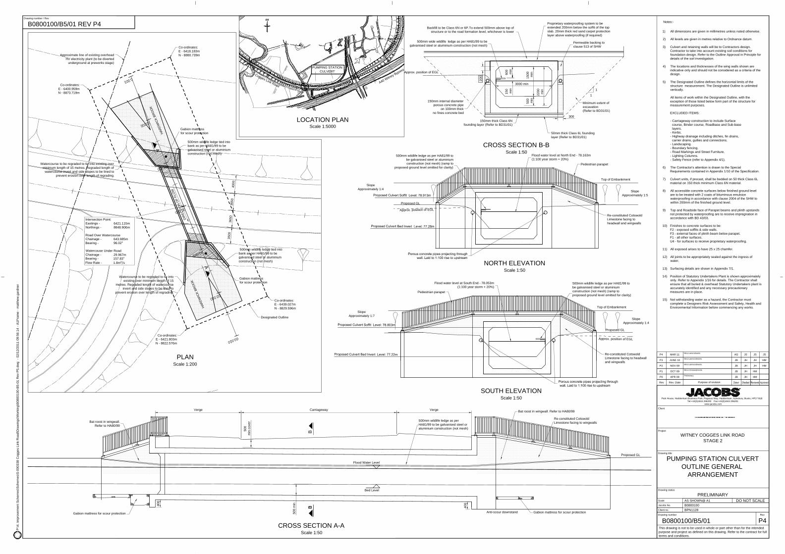
Notes:-
1)
2)
3)
4)
5)
6)
7)
8)
9)
10)
11)
12)
13)
14)
15)
All dimensions are given in millimetres unless noted otherwise.
All levels are given in metres relative to Ordnance datum.
Culvert and retaining walls will be to Contractors design.Contractor to take into account existing soil conditions forfoundation design. Refer to the Approval in Principle for detailsof the soil investigation.
The locations and thicknesses of the wing walls shown areindicative only and should not be considered as a criteria of thedesign.
The Designated Outline defines the horizontal limits of thestructure measurement. The Designated Outline is unlimitedvertically.
All items of work within the Designated Outline, with theexception of those listed below form part of the structure formeasurement purposes.
EXCLUDED ITEMS:
- Carriageway construction to include Surface course, Binder course, Roadbase and Sub-base layers.- Kerbs.- Highway drainage including ditches, fin drains, carrier drains, gullies and connections.- Landscaping.- Boundary fencing.- Road Markings and Street Furniture.- Lighting Columns.- Safety Fence (refer to Appendix 4/1).
The Contractor's attention is drawn to the SpecialRequirements contained in Appendix 1/10 of the Specification.
Culvert units, if precast, shall be bedded on 50 thick Class 6Lmaterial on 150 thick minimum Class 6N material.
All accessible concrete surfaces below finished ground levelare to be treated with 2 coats of bituminous emulsionwaterproofing in accordance with clause 2004 of the SHW towithin 200mm of the finished ground level.
Top and Roadside face of Parapet beams and plinth upstandsnot protected by waterproofing are to receive impregnation inaccordance with BD 43/03.
Finishes to concrete surfaces to be:F2 - exposed soffits & side walls.F3 - external faces of plinth beam below parapet.F1 - all other surfaces.U4 - for surfaces to receive proprietary waterproofing.
All exposed arises to have 25 x 25 chamfer.
All joints to be appropriately sealed against the ingress ofwater.
Surfacing details are shown in appendix 7/1.
Position of Statutory Undertakers Plant is shown approximatelyonly. Refer to Appendix 1/16 for details. The Contractor shallensure that all buried & overhead Statutory Undertakers plant isaccurately identified and any necessary precautionarymeasures are in place.
Not withstanding water as a hazard, the Contractor mustcomplete a Designers Risk Assessment and Safety, Health andEnvironmental Information before commencing any works.
This drawing is not to be used in whole or part other than for the intendedpurpose and project as defined on this drawing. Refer to the contract for fullterms and conditions.
Drawing status
Drawing number
Scale
Client no.
Jacobs No.
Drawing title
DO NOT SCALE
Rev
Project
Client
WITNEY COGGES LINK ROADSTAGE 2
FARM MILL CULVERTOUTLINE GENERAL
ARRANGEMENT
PRELIMINARYAS SHOWN@ A1B0800100BPN1128
B0800100/B4/01 P6
B0800100/B4/01 REV P6
Purpose of revisionRev Rev. Date
P0 APR 09 Preliminary JB JH HM
Park House, Haddenham Business Park, Pegasus Way, Haddenham, Aylesbury, Bucks, HP17 8LBTel:+44(0)1844 296200 Fax:+44(0)1844 296201
www.jacobs.com
P1 OCT 09 Minor Ammendments JB JH HM
P2 NOV 09 Minor Ammendments JB JH JH HM
P3 MAY 10 Minor ammendments JB JH JH HM
P4 JUNE 10 Addition of Safety Fence GB JH JH HM
P5 MAR 11 Minor amendments AG JS JS JS
P6 SEPT 11 Minor amendments MG AG MJCo MJCo
300
200
1
1
Approx. position of EGL
Backfill to be Class 6N or 6P.To extend 500mm above top ofstructure or to the road formation level, whichever is lower
Minimum extent ofexcavation(Refer to BD31/01)
50mm thick Class 6L foundinglayer (Refer to BD31/01)
150mm thick Class 6Nfounding layer (Refer to BD31/01)
150mm internal diameterporous concrete pipe
on 100mm thickno fines concrete bed
Permeable backing toclause 513 of SHW
Proprietary waterproofing system to beextended 200mm below the soffit of the topslab. 20mm thick red sand carpet protectionlayer above waterproofing (if required)
3000 min
2200
min
500
min
150
min
600
min
Approx. position of EGL
Flood water level at North End - 78.163m(1:100 year storm + 20%)
500mm wildlife ledge as per HA81/99 tobe galvanised steel or aluminiumconstruction (not mesh) (ramp to
proposed ground level omitted for clarity)
Re-constituted CotswoldLimestone facing toheadwall and wingwalls
Pedestrian parapet
Top of Embankment
Proposed GL
NORTH ELEVATIONScale 1:50
CROSS SECTION B-BScale 1:50
500mm wide wildlife ledge as per HA81/99 to begalvanised steel or aluminium construction (not mesh)
Approx. position of EGL
Flood water level at South End - 78.053m(1:100 year storm + 20%)
500mm wildlife ledge as per HA81/99 tobe galvanised steel or aluminiumconstruction (not mesh) (ramp toproposed ground level omitted for clarity)
Pedestrian parapet
Top of Embankment
Proposed GL
SOUTH ELEVATIONScale 1:50
Re-constituted CotswoldLimestone facing to headwalland wingwalls
1500
min
SlopeApproximately 1:5
SlopeApproximately 1:4
SlopeApproximately 1:7
SlopeApproximately 1:4
LOCATION PLANScale 1:5000
Cogges Link RoadA40 Witney Bypass
PUMPING STATIONCULVERT
Ch.500
Ch.1000
Ch.500
Ch.1000
B 400
Anti-scour downstand
400
500
min
CROSS SECTION A-AScale 1:50
Gabion mattress for scour protection Gabion mattress for scour protection
500mm wildlife ledge as perHA81/99 to be galvanised steel oraluminium construction (not mesh)
Re-constituted CotswoldLimestone facing to wingwalls
CarriagewayVerge Verge
500
min
cov
er
Proposed GL
Bat roost in wingwall. Refer to HA80/99
Bat roost in wingwall.Refer to HA80/99
BB
Bed Level
Flood Water Level
A
A
PLANScale 1:200
Gabion mattressfor scour protection
500mm wildlife ledge tied intobank as per HA81/99 to begalvanised steel or aluminiumconstruction (not mesh)
500mm wildlife ledge tied intobank as per HA81/99 to begalvanised steel or aluminiumconstruction (not mesh)
Watercourse to be regraded to tie into existing overminimum length of 15 metres. Regraded length of
watercourse invert and side slopes to be lined toprevent erosion over length of regrading.
Watercourse to be regraded to tie intoexisting over minimum length of 15
metres. Regraded length of watercourseinvert and side slopes to be lined to
prevent erosion over length of regrading.
Co-ordinates:E - 6439.027mN - 8829.596m
Co-ordinates:E - 6418.183mN - 8880.739m
Co-ordinates:E - 6400.959mN - 8873.719m
Co-ordinates:E - 6421.803mN - 8822.576m
Gabion mattressfor scour protection
Designated Outline
DIRE
CTIO
N O
F FL
OW
HARD
WIC
K BR
OO
K
HARD
WIC
K BR
OO
K
Approximate line of existing overheadHV electricity plant (to be diverted
underground at preworks stage)
Intersection Point:Eastings - 6421.115mNorthings - 8848.906m
Road Over WatercourseChainage - 643.985mBearing - 96.02°
Watercouse Under RoadChainage - 29.967mBearing - 157.83°Flow Rate - 1.8m³/s
3650
3650
4000
3500
Notes:-
1)
2)
3)
4)
5)
6)
7)
8)
9)
10)
11)
12)
13)
14)
15)
All dimensions are given in millimetres unless noted otherwise.
All levels are given in metres relative to Ordnance datum.
Culvert and retaining walls will be to Contractors design.Contractor to take into account existing soil conditions forfoundation design. Refer to the Outline Approval in Principle fordetails of the soil investigation.
The locations and thicknesses of the wing walls shown areindicative only and should not be considered as a criteria of thedesign.
The Designated Outline defines the horizontal limits of thestructure measurement. The Designated Outline is unlimitedvertically.
All items of work within the Designated Outline, with theexception of those listed below form part of the structure formeasurement purposes.
EXCLUDED ITEMS:
- Carriageway construction to include Surface course, Binder course, Roadbase and Sub-base layers.- Kerbs.- Highway drainage including ditches, fin drains, carrier drains, gullies and connections.- Landscaping.- Boundary fencing.- Road Markings and Street Furniture.- Lighting Columns.- Safety Fence (refer to Appendix 4/1).
The Contractor's attention is drawn to the SpecialRequirements contained in Appendix 1/10 of the Specification.
Culvert units, if precast, shall be bedded on 50 thick Class 6Lmaterial on 150 thick minimum Class 6N material.
All accessible concrete surfaces below finished ground levelare to be treated with 2 coats of bituminous emulsionwaterproofing in accordance with clause 2004 of the SHW towithin 200mm of the finished ground level.
Top and Roadside face of Parapet beams and plinth upstandsnot protected by waterproofing are to receive impregnation inaccordance with BD 43/03.
Finishes to concrete surfaces to be:F2 - exposed soffits & side walls.F3 - external faces of plinth beam below parapet.F1 - all other surfaces.U4 - for surfaces to receive proprietary waterproofing.
All exposed arises to have 25 x 25 chamfer.
All joints to be appropriately sealed against the ingress ofwater.
Surfacing details are shown in Appendix 7/1.
Position of Statutory Undertakers Plant is shown approximatelyonly. Refer to Appendix 1/16 for details. The Contractor shallensure that all buried & overhead Statutory Undertakers plant isaccurately identified and any necessary precautionarymeasures are in place.
Not withstanding water as a hazard, the Contractor mustcomplete a Designers Risk Assessment and Safety, Health andEnvironmental Information before commencing any works.
This drawing is not to be used in whole or part other than for the intendedpurpose and project as defined on this drawing. Refer to the contract for fullterms and conditions.
Drawing status
Drawing number
Scale
Client no.
Jacobs No.
Drawing title
DO NOT SCALE
Rev
Project
Client
Drawing number / RevP
:\4. I
mpr
ovem
ent S
chem
es\S
chem
es\S
-000
338
Cog
ges
Link
Roa
d\D
raw
ings
\Wor
king
\B08
0010
0-B
5-01
Rev
P5.
dwg
- 02
/12/
2011
09:
56:1
4 - A
1Fra
me
- mat
thew
.gar
dner
WITNEY COGGES LINK ROADSTAGE 2
PUMPING STATION CULVERTOUTLINE GENERAL
ARRANGEMENT
PRELIMINARYAS SHOWN@ A1B0800100BPN1128
B0800100/B5/01 P4
B0800100/B5/01 REV P4
Purpose of revisionRev Rev. Date
P2 NOV 09 Minor ammendments JB JH JH HM
Park House, Haddenham Business Park, Pegasus Way, Haddenham, Aylesbury, Bucks, HP17 8LBTel:+44(0)1844 296200 Fax:+44(0)1844 296201
www.jacobs.com
P0 APR 09 Preliminary JB JH HM
P1 OCT 09 Minor Ammendments JB JH HM
P3 JUNE 10 Minor ammendments JB JH JH HM
P4 MAR 11 Minor amendments AG JS JS JS

Eastern Pond Complex
River W
indrush (East Branch)
24.0
28.4m
27.1m
PLANSCALE: 1-250
High voltage cableover River Windrush
SOUTH ELEVATIONTIMBER CLAD STEEL BRIDGE
SCALE: 1:100
24.0
0.6m minimumbank clearance
Steel infill panelbetween timberuprights
Timber upright post
Existing ground profile
79.416m79.416m
Timber handrail
1.4m high post and railtimber fence as HCDH15
Combined cycle/pedestrian footpath
TYPICAL SECTIONTHROUGH RAMP
Scale 1:100
1 in 2 slope 1 in 2 slope
Section shown indicativeonly.It does not representthe actual constructiondetails of the Contractor'schosen design.
TYPICAL SECTION THROUGH STRUCTUREScale 1:50
MaxConstruction
depth
B
B
0
Location
8072
,98
11323,18
Notes:-
All dimensions are in millimetres unless stated otherwise.
This drawing shall be read in conjunction with Appendix 1/10with regard to special requirements and Appendix 4/1 of thespecification with regard to pedestrian parapet requirements.
The height of the parapet shall be 1.4M high.The pedestrian parapet shall conform to:Design Loading Class: Class 3Infill Class: Class CInfill Type: Vertical Infill : full height
The details shown on this drawing are indicative of the generalform and features of the structure. Actual dimensions, featuresand finishes will be dependant upon the actual design chosenby the Contractor.
All approach ramps to have a slope of 1:20 unless indicatedotherwise.
Contractor to propose decking and surface type for thestructure.
The structure is to be clad with Ekki tropical hardwood with aD60 strength class as stated in BS 5268: Pt.2 or a timber withsimilar characteristics. To be approved by the ContractAdministrator.
All connections are to be stainless steel.
1)
2)
3)
4)
5)
6)
7)
8)
Oxfordshire County CouncilSpeedwell HouseSpeedwell StreetOxfordOX1 1NETel: (01865) 815700Fax: (01865) 241577
Deputy Director ofSteve Howell
Environment & Economy
Approv'dCheckedDrawnPurpose of revisionDateRev.
Reproduced from the Ordnance Survey mapping with the permission of the Controller ofHer Majesty's Stationery Office © Crown Copyright. Unauthorised reproductioninfringes Crown Copyright, and may lead to prosecution or civil proceedings. OxfordshireCounty Council Licence No LA076805
P:\4
. Im
prov
emen
t Sch
emes
\Sch
emes
\S-0
0033
8 C
ogge
s Li
nk R
oad\
Dra
win
gs\W
orki
ng\ti
mbe
r foo
tbrid
ge n
ew.d
wg
COGGES LINK ROAD
TIMBER CLAD STEEL BEAMFOOTBRIDGE OUTLINE
ARRANGEMENT
AS STATED AGNOV 11
RCNOV 11
MJCoNOV 11
HQ22135
HQ22135/CLR/EA/17 0
HQ22135/CLR/EA/17 0
PROPSED LOCATION PLANScale 1:5000
0 Dec 11 Original drawing AG RC MJCo


