AN-000158 This document contains information on a pre-production product and should not be considered for production until qualification is complete. Chirp Microsystems reserves the right to change specifications and information herein without notice. Chirp Microsystems 2560 Ninth Street, Ste 200, Berkeley, CA 94710 U.S.A +1(510) 640–8155 www.chirpmicro.com Document Number: AN-000158 Revision: 1.1 Release Date: 09/29/2020 CH101 Mechanical Integration Guide
Transcript
AN-000158
This document contains information on a pre-production product and should not be considered for production until qualification is complete. Chirp Microsystems reserves the right to change specifications and information herein without notice.
Document Number: AN-000158 Page 2 of 21 Revision: 1.1
1 INTRODUCTION The purpose of this document is to provide recommendations and guidance on the mechanical integration of Chirp CH101 ultrasonic sensors in device enclosures. This document will cover the mechanical design, geometry, part and assembly tolerances, material considerations, testing, and best practices for mechanical integration. All dimensions mentioned in this document are in mm, unless otherwise specified.
The information in this guide only covers information related specifically to Chirp Microsystems’ CH101 sensors, and not other sensors, such as the CH201. If you are integrating other Chirp Microsystems sensors, please consult the appropriate Mechanical Integration Guide for that product.
AN-000158
Document Number: AN-000158 Page 3 of 21 Revision: 1.1
2 ACRONYMS AND ABBREVIATIONS Some commonly used acronyms and abbreviations in this document are listed below:
8 REVISION HISTORY ................................................................................................................................................................... 21
AN-000158
Document Number: AN-000158 Page 5 of 21 Revision: 1.1
3 OVERVIEW THEORY OF OPERATION
The CH101 is an ultrasonic transceiver rangefinder that uses a piezoelectric micromachined ultrasonic transducer (PMUT) to send out short pulses of soundwaves into the air. Upon hitting an object, these waves reflect back towards the PMUT, causing it to vibrate and generate an electrical signal. The time needed for the soundwaves to travel from and back to the PMUT, known as the Time-of-Flight (ToF), is measured by the built-in application-specific integrated circuit (ASIC). Using the speed of sound (343 m/s at room temperature), the system can determine the distance to the object.
Unlike other types of ToF rangefinders, such as infrared (IR) sensors, the CH101 is not affected by the color or transparency of objects and works in all lighting conditions. It also uses significantly less power than comparable IR sensors and the CH101’s Field-of-View (FoV) can be customized by different acoustic housings.
PACKAGE DIMENSIONS
Figure 1. Package dimensions of the CH101.
AN-000158
Document Number: AN-000158 Page 6 of 21 Revision: 1.1
SENSOR CONFIGURATIONS
As an ultrasonic transceiver, the CH101 is capable of measuring distances to objects just by itself. However, a network of CH101 sensors can be used together for additional functionality such as 2D and 3D location identification. The most common sensor configurations are detailed below.
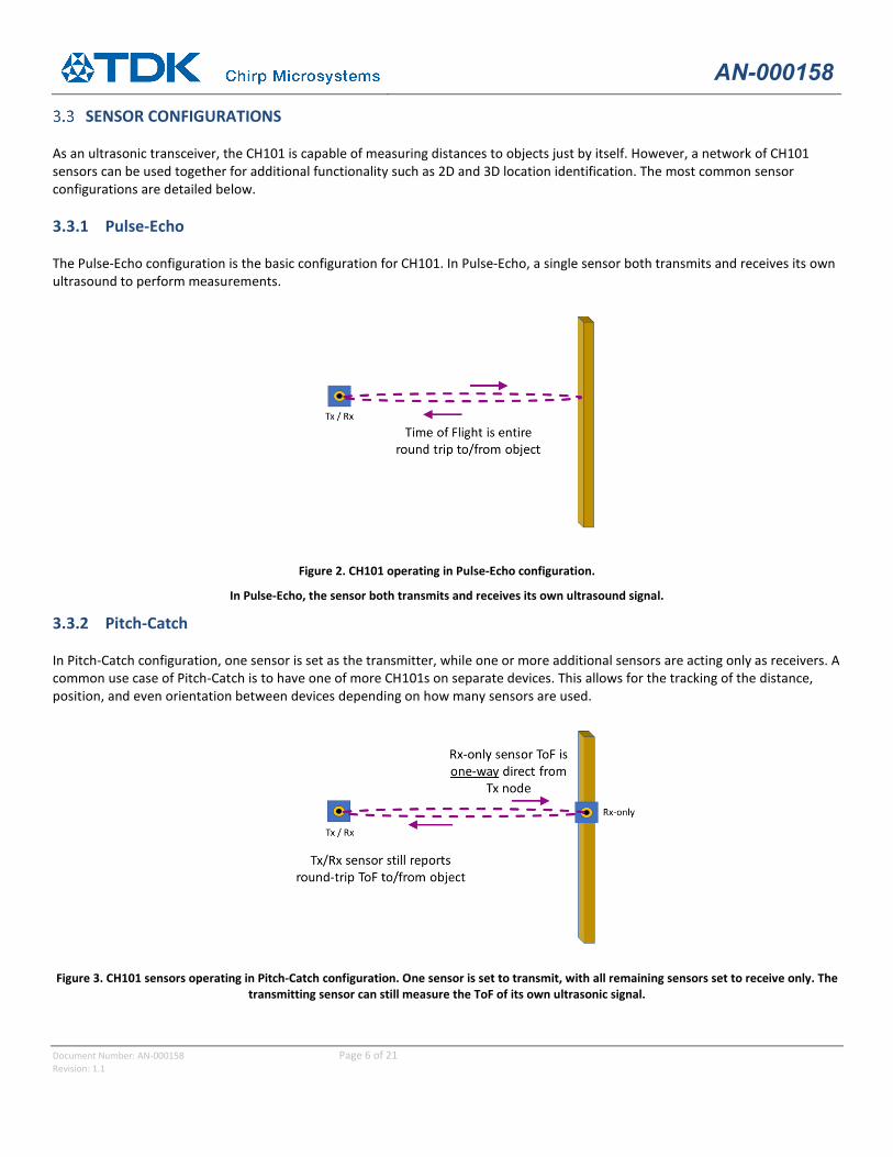
3.3.1 Pulse-Echo
The Pulse-Echo configuration is the basic configuration for CH101. In Pulse-Echo, a single sensor both transmits and receives its own ultrasound to perform measurements.
Figure 2. CH101 operating in Pulse-Echo configuration.
In Pulse-Echo, the sensor both transmits and receives its own ultrasound signal.
3.3.2 Pitch-Catch
In Pitch-Catch configuration, one sensor is set as the transmitter, while one or more additional sensors are acting only as receivers. A common use case of Pitch-Catch is to have one of more CH101s on separate devices. This allows for the tracking of the distance, position, and even orientation between devices depending on how many sensors are used.
Figure 3. CH101 sensors operating in Pitch-Catch configuration. One sensor is set to transmit, with all remaining sensors set to receive only. The
transmitting sensor can still measure the ToF of its own ultrasonic signal.
AN-000158
Document Number: AN-000158 Page 7 of 21 Revision: 1.1
4 ACOUSTIC INTERFACES The CH101 without an Acoustic Interface has poor sound output performance. The reason for this is the large acoustic impedance difference between the PMUT (the source) and the air (the load) resulting in the energy from the PMUT not being transferred efficiently to the air. In this regard, acoustic impedance can be thought of as analogous to electrical impedance. To improve the transfer of sound energy to the air, an Acoustic Interface is required in front of the CH101 port hole to better match the impedance. In addition, the dimensions and geometry of the Acoustic Interface dictate the FoV of the sensor. Two broad categories of Acoustic Interface are used with the CH101: tubes and horns.
TUBES Tubes are holes of a specific length and diameter. For the CH101, the optimal tube length is 0.475 mm with a diameter of 0.7 mm. A straight tube is the Acoustic Interface of choice for applications that require the smallest opening possible. Straight tubes are always omnidirectional (~180 degree FoV).
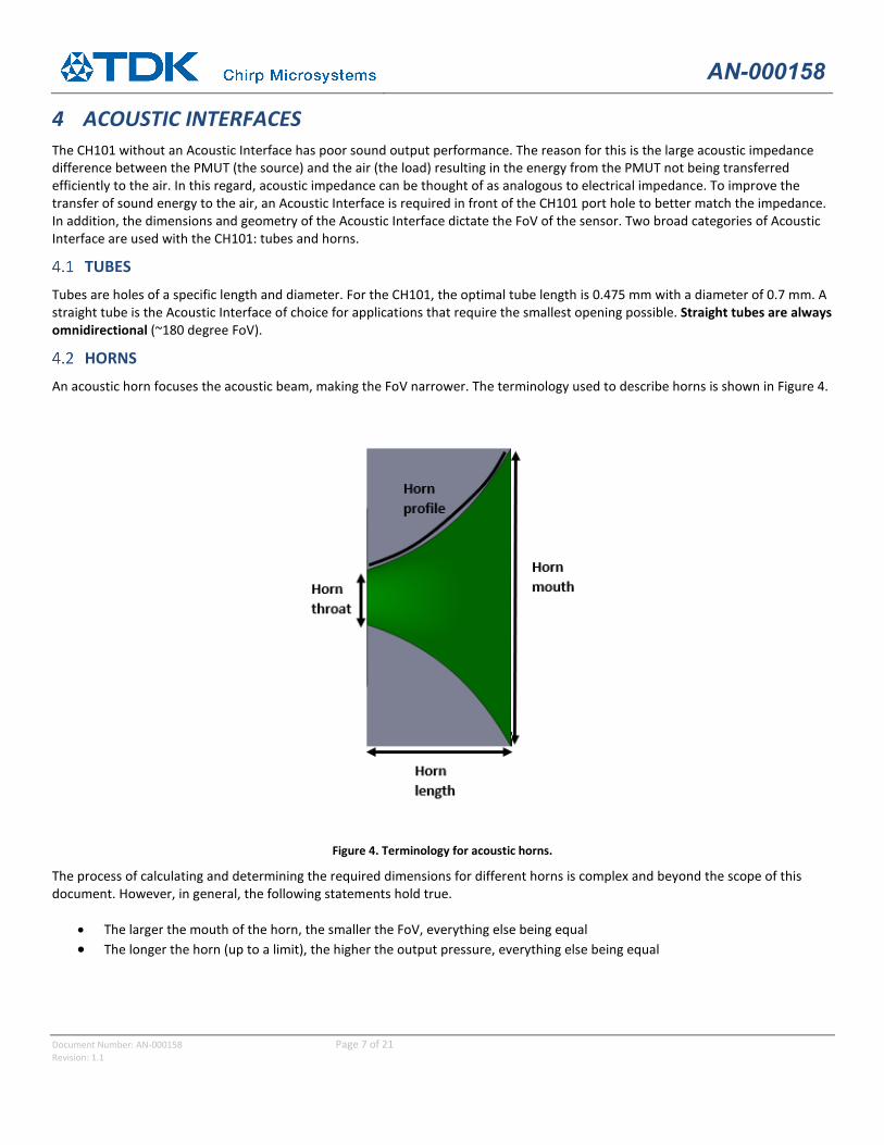
HORNS An acoustic horn focuses the acoustic beam, making the FoV narrower. The terminology used to describe horns is shown in Figure 4.
Figure 4. Terminology for acoustic horns. The process of calculating and determining the required dimensions for different horns is complex and beyond the scope of this document. However, in general, the following statements hold true.
• The larger the mouth of the horn, the smaller the FoV, everything else being equal • The longer the horn (up to a limit), the higher the output pressure, everything else being equal
AN-000158
Document Number: AN-000158 Page 8 of 21 Revision: 1.1
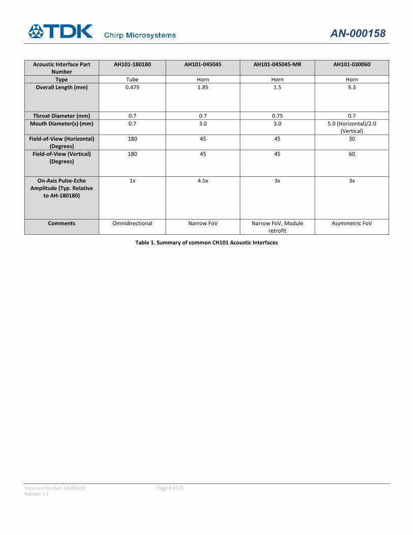
Table 1. Summary of common CH101 Acoustic Interfaces
AN-000158
Document Number: AN-000158 Page 9 of 21 Revision: 1.1
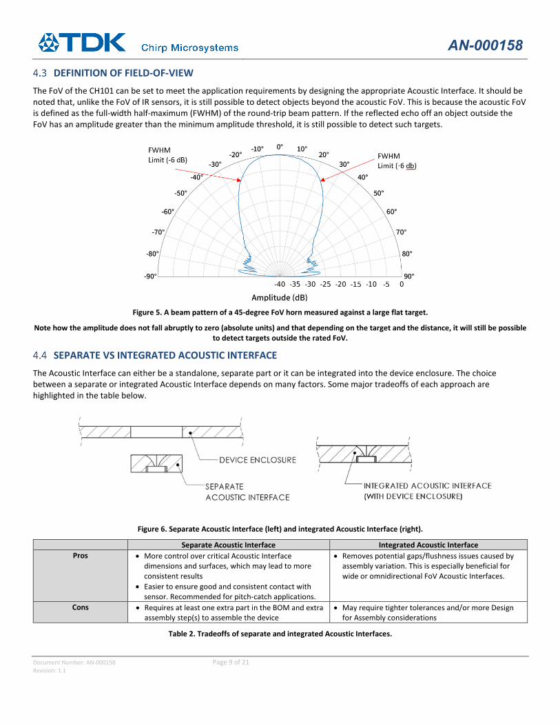
DEFINITION OF FIELD-OF-VIEW The FoV of the CH101 can be set to meet the application requirements by designing the appropriate Acoustic Interface. It should be noted that, unlike the FoV of IR sensors, it is still possible to detect objects beyond the acoustic FoV. This is because the acoustic FoV is defined as the full-width half-maximum (FWHM) of the round-trip beam pattern. If the reflected echo off an object outside the FoV has an amplitude greater than the minimum amplitude threshold, it is still possible to detect such targets.
Figure 5. A beam pattern of a 45-degree FoV horn measured against a large flat target.
Note how the amplitude does not fall abruptly to zero (absolute units) and that depending on the target and the distance, it will still be possible to detect targets outside the rated FoV.
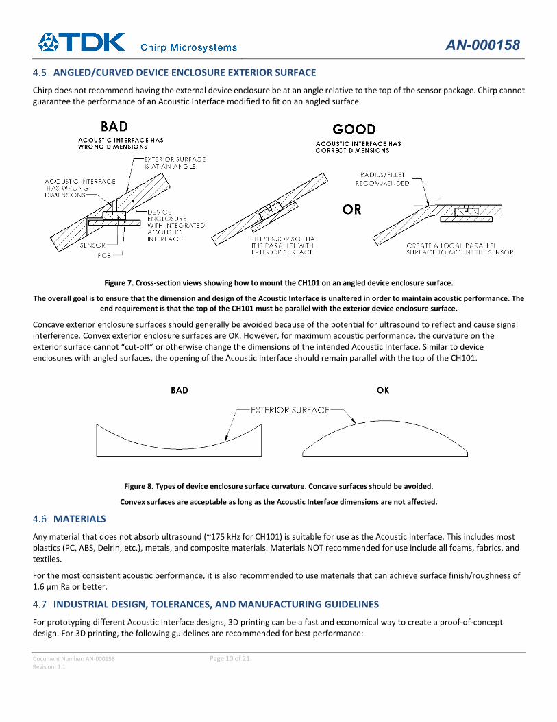
SEPARATE VS INTEGRATED ACOUSTIC INTERFACE The Acoustic Interface can either be a standalone, separate part or it can be integrated into the device enclosure. The choice between a separate or integrated Acoustic Interface depends on many factors. Some major tradeoffs of each approach are highlighted in the table below.
Figure 6. Separate Acoustic Interface (left) and integrated Acoustic Interface (right).
Separate Acoustic Interface Integrated Acoustic Interface Pros • More control over critical Acoustic Interface
dimensions and surfaces, which may lead to more consistent results
• Easier to ensure good and consistent contact with sensor. Recommended for pitch-catch applications.
• Removes potential gaps/flushness issues caused by assembly variation. This is especially beneficial for wide or omnidirectional FoV Acoustic Interfaces.
Cons • Requires at least one extra part in the BOM and extra assembly step(s) to assemble the device
• May require tighter tolerances and/or more Design for Assembly considerations
Table 2. Tradeoffs of separate and integrated Acoustic Interfaces.
AN-000158
Document Number: AN-000158 Page 10 of 21 Revision: 1.1
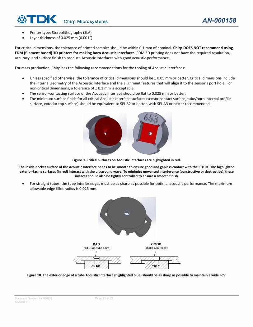
ANGLED/CURVED DEVICE ENCLOSURE EXTERIOR SURFACE Chirp does not recommend having the external device enclosure be at an angle relative to the top of the sensor package. Chirp cannot guarantee the performance of an Acoustic Interface modified to fit on an angled surface.
Figure 7. Cross-section views showing how to mount the CH101 on an angled device enclosure surface.
The overall goal is to ensure that the dimension and design of the Acoustic Interface is unaltered in order to maintain acoustic performance. The end requirement is that the top of the CH101 must be parallel with the exterior device enclosure surface.
Concave exterior enclosure surfaces should generally be avoided because of the potential for ultrasound to reflect and cause signal interference. Convex exterior enclosure surfaces are OK. However, for maximum acoustic performance, the curvature on the exterior surface cannot “cut-off” or otherwise change the dimensions of the intended Acoustic Interface. Similar to device enclosures with angled surfaces, the opening of the Acoustic Interface should remain parallel with the top of the CH101.
Figure 8. Types of device enclosure surface curvature. Concave surfaces should be avoided.
Convex surfaces are acceptable as long as the Acoustic Interface dimensions are not affected.
MATERIALS Any material that does not absorb ultrasound (~175 kHz for CH101) is suitable for use as the Acoustic Interface. This includes most plastics (PC, ABS, Delrin, etc.), metals, and composite materials. Materials NOT recommended for use include all foams, fabrics, and textiles.
For the most consistent acoustic performance, it is also recommended to use materials that can achieve surface finish/roughness of 1.6 μm Ra or better.
INDUSTRIAL DESIGN, TOLERANCES, AND MANUFACTURING GUIDELINES For prototyping different Acoustic Interface designs, 3D printing can be a fast and economical way to create a proof-of-concept design. For 3D printing, the following guidelines are recommended for best performance:
AN-000158
Document Number: AN-000158 Page 11 of 21 Revision: 1.1
• Printer type: Stereolithography (SLA) • Layer thickness of 0.025 mm (0.001”)
For critical dimensions, the tolerance of printed samples should be within 0.1 mm of nominal. Chirp DOES NOT recommend using FDM (filament based) 3D printers for making horn Acoustic Interfaces. FDM 3D printing does not have the required resolution, accuracy, and surface finish to produce Acoustic Interfaces with good acoustic performance.
For mass production, Chirp has the following recommendations for the tooling of Acoustic Interfaces:
• Unless specified otherwise, the tolerance of critical dimensions should be ± 0.05 mm or better. Critical dimensions include the internal geometry of the Acoustic Interface and the alignment features that will align it to the sensor’s port hole. For non-critical dimensions, a tolerance of ± 0.1 mm is acceptable.
• The sensor-contacting surface of the Acoustic Interface should be flat to 0.025 mm or better. • The minimum surface finish for all critical Acoustic Interface surfaces (sensor contact surface, tube/horn internal profile
surface, exterior top surface) should be equivalent to SPI-B2 or better, with SPI-A3 or better recommended.
Figure 9. Critical surfaces on Acoustic Interfaces are highlighted in red.
The inside pocket surface of the Acoustic Interface needs to be smooth to ensure good and gapless contact with the CH101. The highlighted exterior-facing surfaces (in red) interact with the ultrasound wave. To minimize unwanted interference (constructive or destructive), these
surfaces should also be tightly controlled to ensure a smooth finish.
• For straight tubes, the tube interior edges must be as sharp as possible for optimal acoustic performance. The maximum allowable edge fillet radius is 0.025 mm.
Figure 10. The exterior edge of a tube Acoustic Interface (highlighted blue) should be as sharp as possible to maintain a wide FoV.
AN-000158
Document Number: AN-000158 Page 12 of 21 Revision: 1.1
5 PARTICLE INGRESS FILTERS Using a protective covering or Particle Ingress Filter (PIF) over the CH101 is recommended if dust, liquid or other contaminants are present in the application environment. For the CH101, the currently supported PIF material is SAATI Acoustex B042HY. The B042HY has been tested by Chirp to provide a dust protection rating of IP5X. Due to the small size of the CH101, it is not feasible to test for IP6X, because negative pressure cannot be applied to the part. Should the customer require certification for IP6X, they must run that test independently on their device with the CH101(s) installed.
MESHES AND MEMBRANES There are two broad categories of PIF materials: meshes and membranes. Meshes are primarily woven material (like fabric), and thus its structure is 2-dimensional and very regular throughout the material. On the other hand, membranes are often nonwoven material, so they inherently have a randomness in their structure. An example of a nonwoven membrane material would be expanded PTFE. Membranes can also be solid, thin barriers, like polyester or mylar films.
Figure 11. Representative close-up images of the structure of woven meshes (left) and nonwoven membranes (right).
A natural consequence of the difference in meshes vs membranes is that meshes generally have a smaller acoustic performance impact and reduced ingress protection capability compared to membranes.
Mesh Membrane • Often woven, fabric-like material with a grid-like, regular,
“2D” structure. • Simpler, more predictable structure generally allows for
better airflow, sound transmission and less acoustic performance impact
• Good for IP5X and brief liquid splash or shallow submersion when coated with a hydrophobic coating
• Dust protection is dictated by mesh opening size. Liquid protection is dependent on acoustic path geometry and design.
• Either nonwoven, random structure or a thin solid film • The random structure or solid film aspects of membranes
generally result in higher acoustic performance impact • Materials rated up to IP68 and generally independent of the
Acoustic Interface design and placement of the membrane.
Table 3. Summary table of properties of meshes and membranes.
AN-000158
Document Number: AN-000158 Page 13 of 21 Revision: 1.1
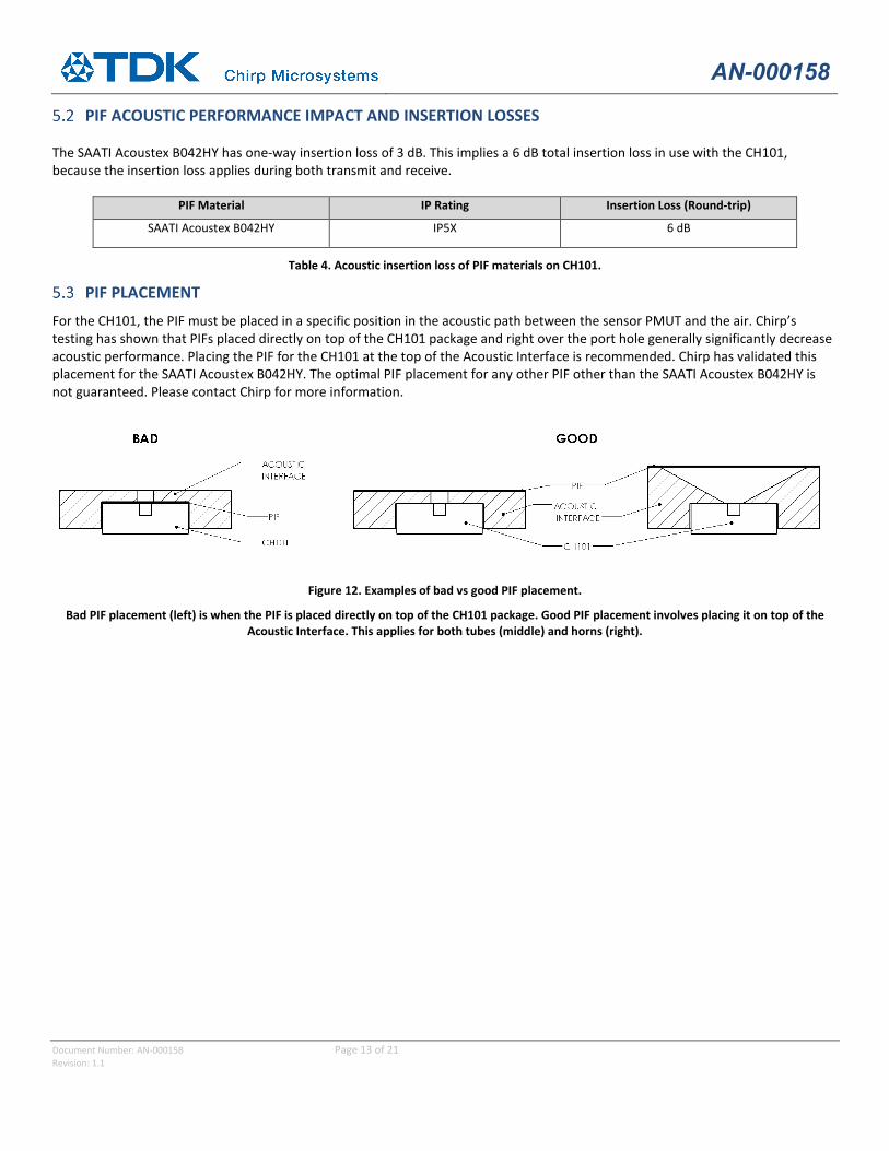
PIF ACOUSTIC PERFORMANCE IMPACT AND INSERTION LOSSES
The SAATI Acoustex B042HY has one-way insertion loss of 3 dB. This implies a 6 dB total insertion loss in use with the CH101, because the insertion loss applies during both transmit and receive.
PIF Material IP Rating Insertion Loss (Round-trip)
SAATI Acoustex B042HY IP5X 6 dB
Table 4. Acoustic insertion loss of PIF materials on CH101.
PIF PLACEMENT For the CH101, the PIF must be placed in a specific position in the acoustic path between the sensor PMUT and the air. Chirp’s testing has shown that PIFs placed directly on top of the CH101 package and right over the port hole generally significantly decrease acoustic performance. Placing the PIF for the CH101 at the top of the Acoustic Interface is recommended. Chirp has validated this placement for the SAATI Acoustex B042HY. The optimal PIF placement for any other PIF other than the SAATI Acoustex B042HY is not guaranteed. Please contact Chirp for more information.
Figure 12. Examples of bad vs good PIF placement.
Bad PIF placement (left) is when the PIF is placed directly on top of the CH101 package. Good PIF placement involves placing it on top of the Acoustic Interface. This applies for both tubes (middle) and horns (right).
AN-000158
Document Number: AN-000158 Page 14 of 21 Revision: 1.1
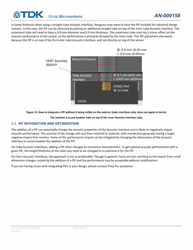
In some instances when using a straight tube Acoustic Interface, designers may want to have the PIF invisible for industrial design reasons. In this case, the PIF can be obscured by placing an additional straight tube on top of the inner tube Acoustic Interface. The outermost tube will need to have a 0.9 mm diameter and 0.9 mm thickness. This outermost tube only has a minor effect on the acoustic performance of the sensor, as the performance is primarily dictated by the inner tube. This PIF placement also works because the PIF is on top of the first inner tube Acoustic Interface, and not directly on top of the sensor.
Figure 13. How to integrate a PIF without it being visible on the exterior (tube interfaces only, does not apply to horns).
The solution is to put another tube on top of the inner Acoustic Interface tube.
PIF INTEGRATION AND OPTIMIZATION The addition of a PIF can potentially change the acoustic properties of the Acoustic Interface and is likely to negatively impact acoustic performance. The severity of the change will vary from material to material, with membranes generally having a larger negative impact than meshes. Some of this performance impact can be mitigated by changing the dimensions of the Acoustic Interface to accommodate the addition of the PIF.
For tube Acoustic Interfaces, adding a PIF often changes its resonance characteristics. To get optimal acoustic performance with a given PIF, the length/thickness of the tube may need to be changed to re-optimize it for the PIF.
For horn Acoustic Interfaces, the approach is not as predictable. Though in general, horns are less sensitive to the impact from small dimension changes caused by the addition of a PIF and the performance may be acceptable without modifications.
If you are having issues with integrating PIFs in your design, please contact Chirp for assistance.
AN-000158
Document Number: AN-000158 Page 15 of 21 Revision: 1.1
6 ASSEMBLY GUIDELINES, TOLERANCES AND REQUIREMENTS CH101 MOUNTING
The recommended method of placing the CH101 in a device is to mount and solder it on its own PCB (FPC, rigid flex or rigid PCB). This PCBA makes it much easier to control the mounting and assembly of the sensor onto the Acoustic Interface, thereby decreasing the chances of poor assembly accuracy and reduced acoustic performance.
RECOMMENDED METHOD FOR SENSOR ASSEMBLY AND ATTACHMENT The assembly method recommended by Chirp for securing the CH101 PCBA to the Acoustic Interface is to use liquid adhesive (glue), because liquid adhesive does not impart additional stress onto the sensor. For all other assembly methods, it is important to verify that the maximum assembly force is not exceeded post-assembly. For example, while gluing the CH101 PCBA to the Acoustic Interface, an operator may temporarily exceed the maximum assembly force, but before the adhesive finishes curing, this excess force must be removed. This can be checked by testing the sensor’s operating frequency before and after assembly. The sensor’s post-assembly operating frequency should not shift beyond a given amount compared to the pre-assembly operating frequency (see Table 5).
The following is a list of adhesives recommended by Chirp for assembling the PCBA onto the Acoustic Interface:
• Dymax 9-911 REV A Ultra-light Weld (UV Cure)
For designs using an Acoustic Interface that is separate from the device enclosure, it is also recommended to use glue to assemble the Acoustic Interface and CH101 PCBA subassembly to the device enclosure, because the maximum assembly force requirement still applies. This method avoids assembly force/stress that can be transferred from the Acoustic Interface and onto the CH101 package.
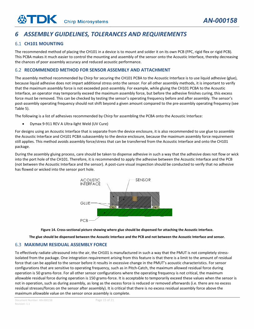
During the assembly gluing process, care should be taken to dispense adhesive in such a way that the adhesive does not flow or wick into the port hole of the CH101. Therefore, it is recommended to apply the adhesive between the Acoustic Interface and the PCB (not between the Acoustic Interface and the sensor). A post-cure visual inspection should be conducted to verify that no adhesive has flowed or wicked into the sensor port hole.
Figure 14. Cross-sectional picture showing where glue should be dispensed for attaching the Acoustic Interface.
The glue should be dispensed between the Acoustic Interface and the PCB and not between the Acoustic Interface and sensor.
MAXIMUM RESIDUAL ASSEMBLY FORCE To effectively radiate ultrasound into the air, the CH101 is manufactured in such a way that the PMUT is not completely stress-isolated from the package. One integration requirement arising from this feature is that there is a limit to the amount of residual force that can be applied to the sensor before it results in excessive change in the PMUT’s acoustic characteristics. For sensor configurations that are sensitive to operating frequency, such as in Pitch-Catch, the maximum allowed residual force during operation is 50 grams-force. For all other sensor configurations where the operating frequency is not critical, the maximum allowable residual force during operation is 150 grams-force. It is acceptable to temporarily exceed these values when the sensor is not in operation, such as during assembly, as long as the excess force is reduced or removed afterwards (i.e. there are no excess residual stresses/forces on the sensor after assembly). It is critical that there is no excess residual assembly force above the maximum allowable value on the sensor once assembly is complete.
AN-000158
Document Number: AN-000158 Page 16 of 21 Revision: 1.1
Sensor Configuration Max Assembly Force (grams-force) Max Allowable Frequency Shift Due to Assembly (Hz)
Pulse-Catch 50 750 Pitch-Echo 150 1500
Table 5. Summary of maximum allowable residual assembly force.
The easiest way to detect when this force is exceeded is to measure the frequency shift from before and after assembly.
One method of holding the module against the device enclosure while avoiding applying excessive force on the module is to use a backplate to transfer the force applied to the module to the Acoustic Interface instead of the sensor (see Figure 15).
Figure 15. Example of a backplate-based module design to avoid applying excessive force on the sensor.
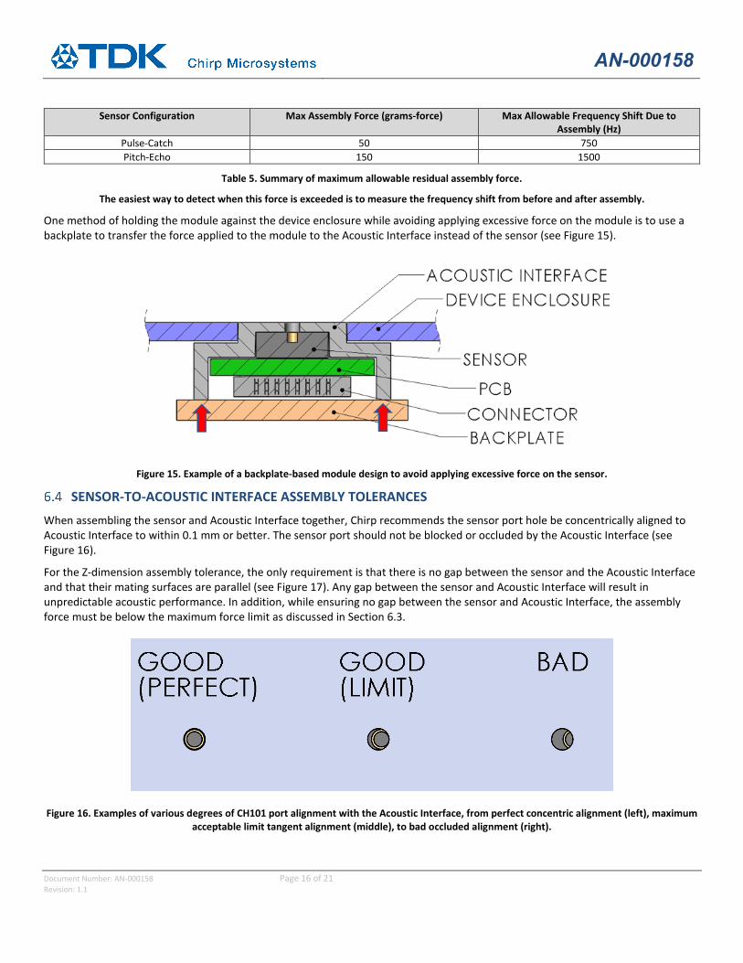
SENSOR-TO-ACOUSTIC INTERFACE ASSEMBLY TOLERANCES When assembling the sensor and Acoustic Interface together, Chirp recommends the sensor port hole be concentrically aligned to Acoustic Interface to within 0.1 mm or better. The sensor port should not be blocked or occluded by the Acoustic Interface (see Figure 16).
For the Z-dimension assembly tolerance, the only requirement is that there is no gap between the sensor and the Acoustic Interface and that their mating surfaces are parallel (see Figure 17). Any gap between the sensor and Acoustic Interface will result in unpredictable acoustic performance. In addition, while ensuring no gap between the sensor and Acoustic Interface, the assembly force must be below the maximum force limit as discussed in Section 6.3.
Figure 16. Examples of various degrees of CH101 port alignment with the Acoustic Interface, from perfect concentric alignment (left), maximum acceptable limit tangent alignment (middle), to bad occluded alignment (right).
AN-000158
Document Number: AN-000158 Page 17 of 21 Revision: 1.1
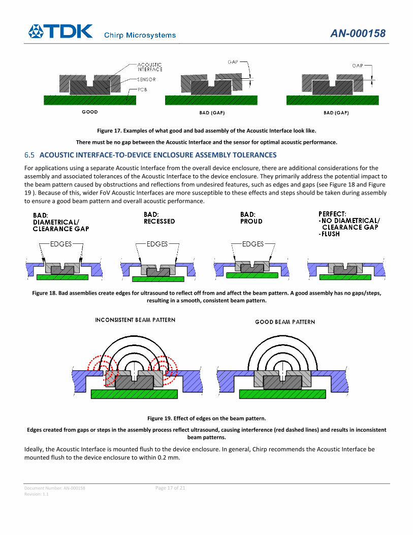
Figure 17. Examples of what good and bad assembly of the Acoustic Interface look like.
There must be no gap between the Acoustic Interface and the sensor for optimal acoustic performance.
ACOUSTIC INTERFACE-TO-DEVICE ENCLOSURE ASSEMBLY TOLERANCES For applications using a separate Acoustic Interface from the overall device enclosure, there are additional considerations for the assembly and associated tolerances of the Acoustic Interface to the device enclosure. They primarily address the potential impact to the beam pattern caused by obstructions and reflections from undesired features, such as edges and gaps (see Figure 18 and Figure 19 ). Because of this, wider FoV Acoustic Interfaces are more susceptible to these effects and steps should be taken during assembly to ensure a good beam pattern and overall acoustic performance.
Figure 18. Bad assemblies create edges for ultrasound to reflect off from and affect the beam pattern. A good assembly has no gaps/steps,
resulting in a smooth, consistent beam pattern.
Figure 19. Effect of edges on the beam pattern.
Edges created from gaps or steps in the assembly process reflect ultrasound, causing interference (red dashed lines) and results in inconsistent beam patterns.
Ideally, the Acoustic Interface is mounted flush to the device enclosure. In general, Chirp recommends the Acoustic Interface be mounted flush to the device enclosure to within 0.2 mm.
AN-000158
Document Number: AN-000158 Page 18 of 21 Revision: 1.1
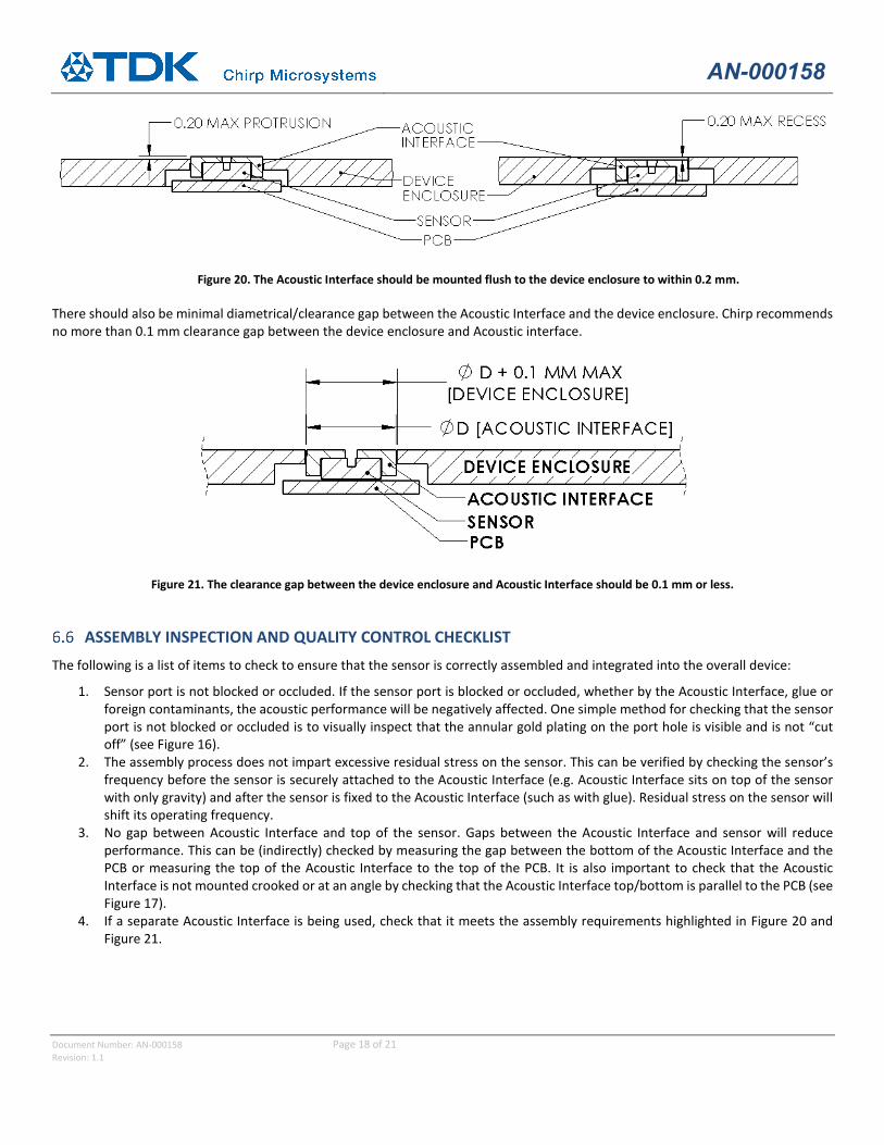
Figure 20. The Acoustic Interface should be mounted flush to the device enclosure to within 0.2 mm.
There should also be minimal diametrical/clearance gap between the Acoustic Interface and the device enclosure. Chirp recommends no more than 0.1 mm clearance gap between the device enclosure and Acoustic interface.
Figure 21. The clearance gap between the device enclosure and Acoustic Interface should be 0.1 mm or less.
ASSEMBLY INSPECTION AND QUALITY CONTROL CHECKLIST The following is a list of items to check to ensure that the sensor is correctly assembled and integrated into the overall device:
1. Sensor port is not blocked or occluded. If the sensor port is blocked or occluded, whether by the Acoustic Interface, glue or foreign contaminants, the acoustic performance will be negatively affected. One simple method for checking that the sensor port is not blocked or occluded is to visually inspect that the annular gold plating on the port hole is visible and is not “cut off” (see Figure 16).
2. The assembly process does not impart excessive residual stress on the sensor. This can be verified by checking the sensor’s frequency before the sensor is securely attached to the Acoustic Interface (e.g. Acoustic Interface sits on top of the sensor with only gravity) and after the sensor is fixed to the Acoustic Interface (such as with glue). Residual stress on the sensor will shift its operating frequency.
3. No gap between Acoustic Interface and top of the sensor. Gaps between the Acoustic Interface and sensor will reduce performance. This can be (indirectly) checked by measuring the gap between the bottom of the Acoustic Interface and the PCB or measuring the top of the Acoustic Interface to the top of the PCB. It is also important to check that the Acoustic Interface is not mounted crooked or at an angle by checking that the Acoustic Interface top/bottom is parallel to the PCB (see Figure 17).
4. If a separate Acoustic Interface is being used, check that it meets the assembly requirements highlighted in Figure 20 and Figure 21.
AN-000158
Document Number: AN-000158 Page 19 of 21 Revision: 1.1
7 SUMMARY DESIGN TRADEOFF CONSIDERATIONS
As with any engineering design, there are always design tradeoffs. When integrating the CH101, the top tradeoff considerations are:
• FoV vs max range: The amount of energy being emitted from the PMUT is finite. To focus the ultrasound beam in a narrow FoV requires taking energy from the sides of the beam pattern. Conversely, to make a wide FoV beam, the sound energy cannot be focused and must be spread out more equally in all directions. Consequently, narrow FoV designs have longer maximum operating range.
• Horn size vs performance: If the application requires a horn (e.g. for increased maximum range or a narrower FoV), the overall acoustic performance can be improved or limited by the size of the horn. In particular, the larger the size of the horn mouth, the smaller the FoV. Generally, a longer horn has more sound output (up to a limit).
• Level of ingress protection vs acoustic performance impact: The more demanding an application’s ingress protection requirement, the more an appropriate PIF material will restrict airflow. The more restrictive material will necessarily reduce the amount of sound output into the air, thus reducing maximum range.
• Assembly tolerance vs acoustic performance consistency: The acoustic performance is the highest when the alignment of all parts in the acoustic path are perfectly concentric with the CH101 port hole. The more the assembly deviates from this ideal alignment, the more the acoustic performance is impacted.
• Separate vs integrated Acoustic Interface: A separate Acoustic Interface will make tighter tolerances possible on critical dimensions, everything else being equal. However, this will result in an additional part in the BOM and assembly and introduce another contribution towards the overall tolerance stack-up. In comparison, an integrated Acoustic Interface has the opposite characteristics and may require tighter tolerances and/or additional Design for Assembly considerations to stay below the allowable maximum residual assembly force.
When working through these considerations for mechanical integration design, keep in mind the overall requirements of the application and device. Depending on the application, one or possibly even all the negative performance tradeoffs may ultimately be inconsequential, because the sensor still performs sufficiently for the application’s needs. As a result, it is worthwhile to test the “worst-case” design and to see how far off it is from meeting the application’s performance requirements.
AN-000158
Document Number: AN-000158 Page 20 of 21 Revision: 1.1
MECHANICAL DESIGN AND INTEGRATION STEPS CHECKLIST 1. Estimate the maximum range (distance) required in your application to detect objects of interest. The Acoustic Interface
(Step 2) and PIF (Step 5) will affect your range from the baseline case.
2. Estimate the FoV needed for your application. Note that Chirp defines the FoV of a sensor at FWHM, essentially the width of the beam pattern at half amplitude. Because of this, it is possible to still detect objects beyond this FoV.
3. Determine your Acoustic Interface design. The combination of Steps 1 and 2 will dictate the Acoustic Interface design for your application. Please consult Table 1 for common Acoustic Interface designs. Note that a wide FoV design will have less range than a narrow FoV design, since the sound energy is being spread over a larger area. For reference, a CH101 with an omnidirectional Acoustic Interface has a 1m range with a 180 deg FoV to a large flat target. Because it is not possible to have a very wide FoV with long range, design tradeoffs in your application may be required.
4. Decide whether the Acoustic Interface will be a stand-alone part or integrated into the device enclosure.
5. Select a PIF that meets your ingress protection requirements, if any. All PIFs will reduce the ultrasound output from the sensor and reduce maximum range. The choice of PIF can dramatically impact the acoustic performance of the sensor (see Table 4). It is very important to test and verify the acoustic performance when using a PIF.
6. Determine the sensor and Acoustic Interface assembly method based on Step 4. Chirp recommends a zero-force assembly method such as gluing to assemble the sensor to your device. Both assembly tolerance and assembly force can impact the sensor acoustic performance, so it is important to verify and compare acoustic performance before and after final assembly.
AN-000158
Document Number: AN-000158 Page 21 of 21 Revision: 1.1
8 REVISION HISTORY
Revision Date Revision Description
4/25/2020 1.0 Initial Release
9/29/2020 1.1 Updated PIF information and assembly inspection information. Reorganized sections. Minor corrections and clarifications.
This information furnished by Chirp Microsystems, Inc. (“Chirp Microsystems”) is believed to be accurate and reliable. However, no responsibility is assumed by Chirp Microsystems for its use, or for any infringements of patents or other rights of third parties that may result from its use. Specifications are subject to change without notice. Chirp Microsystems reserves the right to make changes to this product, including its circuits and software, in order to improve its design and/or performance, without prior notice. Chirp Microsystems makes no warranties, neither expressed nor implied, regarding the information and specifications contained in this document. Chirp Microsystems assumes no responsibility for any claims or damages arising from information contained in this document, or from the use of products and services detailed therein. This includes, but is not limited to, claims or damages based on the infringement of patents, copyrights, mask work and/or other intellectual property rights.
Certain intellectual property owned by Chirp Microsystems and described in this document is patent protected. No license is granted by implication or otherwise under any patent or patent rights of Chirp Microsystems. This publication supersedes and replaces all information previously supplied. Trademarks that are registered trademarks are the property of their respective companies. Chirp Microsystems sensors should not be used or sold in the development, storage, production or utilization of any conventional or mass-destructive weapons or for any other weapons or life threatening applications, as well as in any other life critical applications such as medical equipment, transportation, aerospace and nuclear instruments, undersea equipment, power plant equipment, disaster prevention and crime prevention equipment.


![SNAP Integration Model V. S14 The SNAP Integration Model Mechanical [ SC4 Breakout ] Robin Lafever LBNL Engineering.](https://static.documents.pub/doc/80x56/56649ec65503460f94bd25aa/snap-integration-model-v-s14-the-snap-integration-model-mechanical-sc4-breakout.jpg)


