+ All Categories
Home > Documents > CH390 Datasheet NEW - Data Device Corporation · Decap internal visual inspection 2075 Bond...

CH390 Datasheet NEW - Data Device Corporation · Decap internal visual inspection 2075 Bond...

Date post: 02-Dec-2018
Category:
Upload: vantruc
View: 226 times
Download: 0 times
Share this document with a friend
12
ISOCOM ® LTD For sales enquiries, or further information, please contact our sales office at: Isocom Ltd, 48, Hutton Close, Crowther Industrial Estate, Washington, Tyne and Wear, UK, NE38 0AH Tel: +44 0191 4166 546 Fax: +44 0191 4155 055 ©2007 Copyright reserved to Isocom Limited Page 1 of 12 PART NUMBER CH390/L2S COMPONENT ISSUE 1 SPECIFICATION September 2013 Component Specification For Ceramic Hermetically Sealed, Radiation Hard High Gain Optocoupler M1077 IECQ Further copies of this document may be obtained from: ISOCOM LIMITED WASHINGTON, UK NE38 0AH www.isocom.uk.com
Transcript

ISOCOM®

LTD

For sales enquiries, or further information, please contact our sales office at: Isocom Ltd, 48, Hutton Close, Crowther Industrial Estate, Washington, Tyne and Wear, UK, NE38 0AH Tel: +44 0191 4166 546 Fax: +44 0191 4155 055 ©2007 Copyright reserved to Isocom Limited Page 1 of 12

PART NUMBER CH390/L2S COMPONENT ISSUE 1 SPECIFICATION

September 2013

Component Specification For Ceramic Hermetically Sealed, Radiation Hard

High Gain Optocoupler

M1077 IECQ

Further copies of this document may be obtained from:

ISOCOM LIMITED WASHINGTON, UK

NE38 0AH www.isocom.uk.com

ISOCOM®

LTD

For sales enquiries, or further information, please contact our sales office at: Isocom Ltd, 48, Hutton Close, Crowther Industrial Estate, Washington, Tyne and Wear, UK, NE38 0AH Tel: +44 0191 4166 546 Fax: +44 0191 4155 055 ©2007 Copyright reserved to Isocom Limited Page 2 of 12

Ceramic Hermetically Sealed, Radiation Hard High Gain Optocoupler

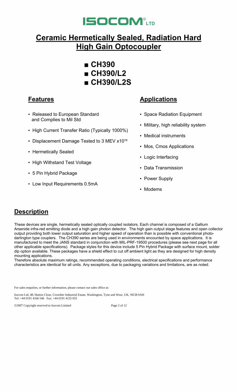
CH390 CH390/L2 CH390/L2S Features Applications Released to European Standard Space Radiation Equipment and Complies to Mil Std Military, high reliability system High Current Transfer Ratio (Typically 1000%) Medical instruments Displacement Damage Tested to 3 MEV x10¹² Mos, Cmos Applications Hermetically Sealed Logic Interfacing High Withstand Test Voltage

Data Transmission 5 Pin Hybrid Package Power Supply Low Input Requirements 0.5mA Modems

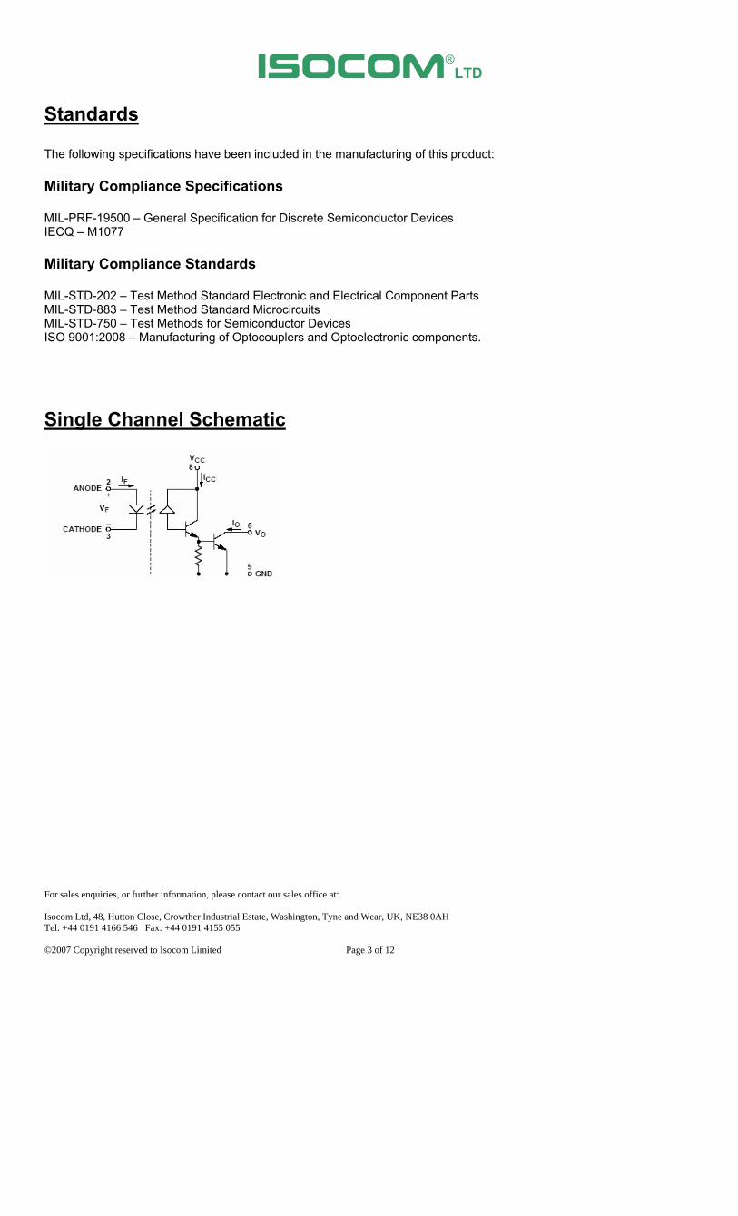
Description These devices are single, hermetically sealed optically coupled isolators. Each channel is composed of a Gallium Arsenide infra-red emitting diode and a high gain photon detector. The high gain output stage features and open collector output providing both lower output saturation and higher speed of operation than is possible with conventional photo-darlington type couplers. The CH390 series are being used in environments encounted by space applications. It is manufactured to meet the JANS standard in conjunction with MIL-PRF-19500 procedures (please see next page for all other applicable specifications). Package styles for this device include 5 Pin Hybrid Package with surface mount, solder dip option available. These packages have a shield effect to cut off ambient light as they are designed for high density mounting applications. Therefore absolute maximum ratings, recommended operating conditions, electrical specifications and performance characteristics are identical for all units. Any exceptions, due to packaging variations and limitations, are as noted.

ISOCOM®

LTD

For sales enquiries, or further information, please contact our sales office at: Isocom Ltd, 48, Hutton Close, Crowther Industrial Estate, Washington, Tyne and Wear, UK, NE38 0AH Tel: +44 0191 4166 546 Fax: +44 0191 4155 055 ©2007 Copyright reserved to Isocom Limited Page 3 of 12

Standards The following specifications have been included in the manufacturing of this product: Military Compliance Specifications MIL-PRF-19500 – General Specification for Discrete Semiconductor Devices IECQ – M1077 Military Compliance Standards MIL-STD-202 – Test Method Standard Electronic and Electrical Component Parts MIL-STD-883 – Test Method Standard Microcircuits MIL-STD-750 – Test Methods for Semiconductor Devices ISO 9001:2008 – Manufacturing of Optocouplers and Optoelectronic components.

Single Channel Schematic

ISOCOM®

LTD

For sales enquiries, or further information, please contact our sales office at: Isocom Ltd, 48, Hutton Close, Crowther Industrial Estate, Washington, Tyne and Wear, UK, NE38 0AH Tel: +44 0191 4166 546 Fax: +44 0191 4155 055 ©2007 Copyright reserved to Isocom Limited Page 4 of 12

Selection Guide Package Styles and Configuration Options

Package 5 pin

Hybrid

Lead Style

Channels 1

Common Channel Wiring

Isocom Part Number and Options

Commercial CH390

Defense Screen Level CH390/L2

Space Screen Level CH390/L2S

Standard Gold Plate Finish Gold Plate

Solder Dipped Option 20

Functional Diagrams

CH390 10 pin Hybrid

1 Channel

Device Marking

ISOCOM

XXXXXXX

XXXX

Manufacturer

Isocom Part Number

Date Code (XX year XX week)

ISOCOM®

LTD

For sales enquiries, or further information, please contact our sales office at: Isocom Ltd, 48, Hutton Close, Crowther Industrial Estate, Washington, Tyne and Wear, UK, NE38 0AH Tel: +44 0191 4166 546 Fax: +44 0191 4155 055 ©2007 Copyright reserved to Isocom Limited Page 5 of 12

Outline Drawings

Absolute Maximum Ratings TA = 25°C U.O.S. Storage Temperature -65°C to +150°C Operating Temperature -55°C to +125°C Lead Soldering Temperature 260°C 1.6mm from case for 10S Input-to-Output Isolation Voltage 1000VDC

Input Diode Peak Forward Current 20mA ≤ 1 mS duration, 500pps Average Forward Current 10mA Reverse Voltage 5V

Output Transistor Supply Voltage 0.5V to 20V Average Current 40mA Power Dissipation 50mW

ISOCOM®

LTD

For sales enquiries, or further information, please contact our sales office at: Isocom Ltd, 48, Hutton Close, Crowther Industrial Estate, Washington, Tyne and Wear, UK, NE38 0AH Tel: +44 0191 4166 546 Fax: +44 0191 4155 055 ©2007 Copyright reserved to Isocom Limited Page 6 of 12

Electrical Characteristics TA = 25°C U.O.S.

Parameter Symbol Test Conditions Min Type Max Units

Vcc =4.5V, Vo=0.4V, IF = 0.5mA 300 700 - %

Vcc =4.5V, Vo=0.4V, IF = 1.6mA 200

1000

- %

Current Transfer Ratio (see notes 4&5) CTR

Vcc =5V, Vo=0.4V, IF = 5mA 200 600 - % Vcc =4.5V, IF = 0.5mA, IoL=1.5mA - 0.1 0.4 V Logic low output voltage

(see note 4) VOL

Vcc =4.5V, IF = 5mA, IoL=10mA - 0.12 0.4 V Logic high output current IoH IF = 2µA, Vo= Vcc=5.5V - 0.001 250 µA

Logic high supply current ICCH IF = 0, Vcc=18V - 0.1 40 µA Logic low supply current (see note 4)

ICCL Vcc=18V, IF = 1.6mA - 1.4 4 mA

Input forward voltage (see note 4)

VF IF = 1.6mA - 1.45 1.9 V

Input-Output Insulation Leakage Current (see note 7 & 13)

II-O RH=45%, t=5S, VI-O= 1500vdc

- - 1.0 µA

Input reverse breakdown (see note 4)

VBR IR = 10µA 5 - - V

RL = 4.7KΩ, Vcc = 5V,IF =0.5mA - 35 100 µS Propagation Delay H-L (see note 4)

tPHL RL = 680Ω, Vcc = 5V,IF = 5mA - 3 12 µS RL = 4.7KΩ, Vcc = 5V,IF =0.5mA - 8 60 µS Propagation Delay

L-H (see note 4) tPLH

RL = 680Ω, Vcc = 5V,IF = 5mA - - 60 µS Common Mode Transient Immunity at Logic High Output (see note 4, 10 &12)

CMH Vcc =5V, IF = 0mA, Vcm =50Vp-p, RL = 2.2KΩ

500 -1000 - V/µS

Common Mode Transient Immunity at Logic Low Output (see note 4, 10 &12)

CML Vcc =5V, IF = 1.6mA, Vcm =50Vp-p, RL = 2.2KΩ

-500 -1000 - V/µS

ISOCOM®

LTD

For sales enquiries, or further information, please contact our sales office at: Isocom Ltd, 48, Hutton Close, Crowther Industrial Estate, Washington, Tyne and Wear, UK, NE38 0AH Tel: +44 0191 4166 546 Fax: +44 0191 4155 055 ©2007 Copyright reserved to Isocom Limited Page 7 of 12

Typical Characteristics TA = 25°C

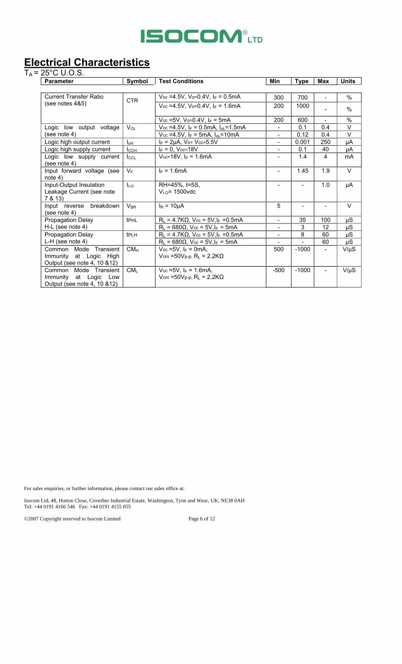
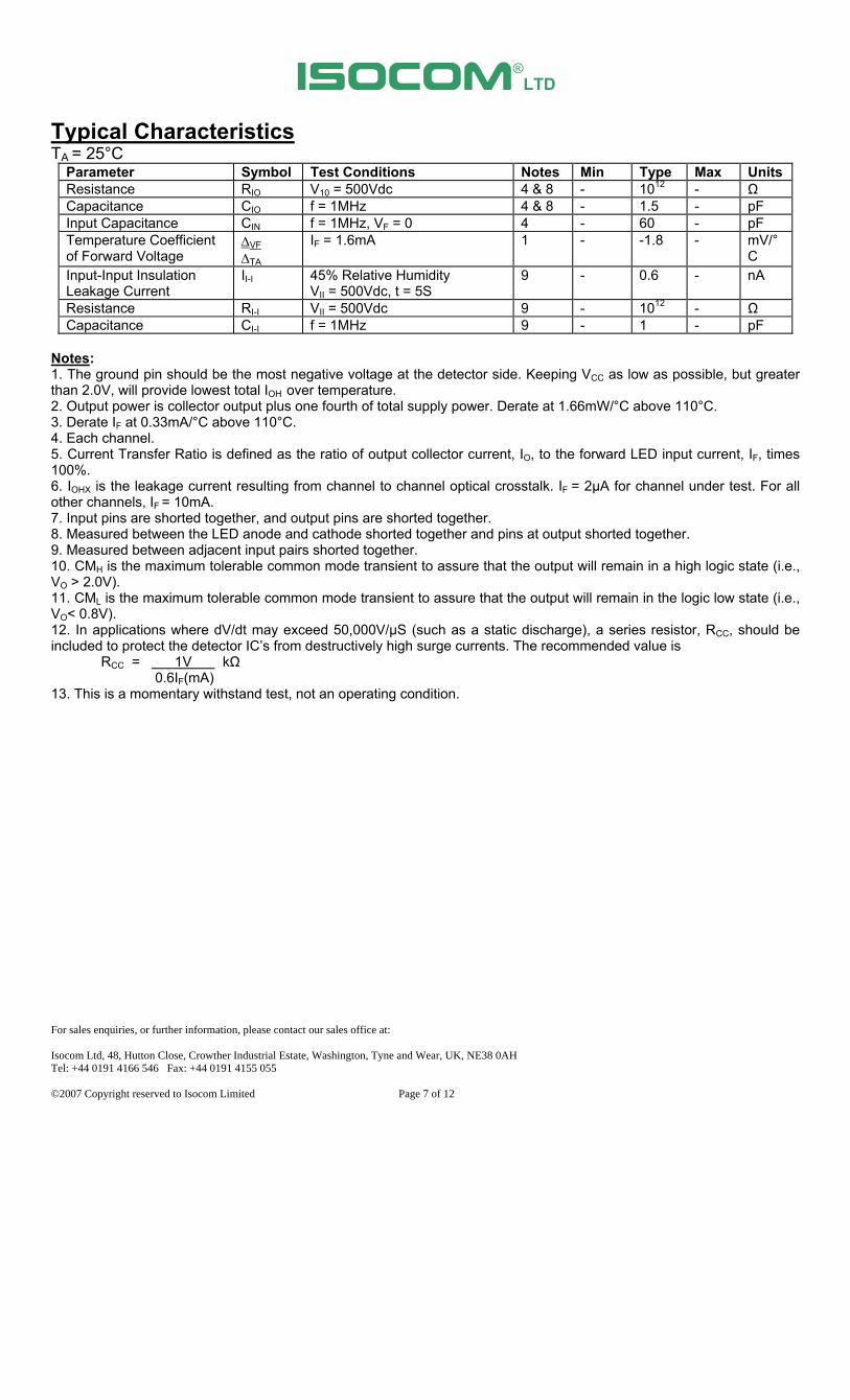
Parameter Symbol Test Conditions Notes Min Type Max Units Resistance RIO V10 = 500Vdc 4 & 8 - 1012 - Ω Capacitance CIO f = 1MHz 4 & 8 - 1.5 - pF Input Capacitance CIN f = 1MHz, VF = 0 4 - 60 - pF Temperature Coefficient of Forward Voltage

VF TA

IF = 1.6mA 1 - -1.8 - mV/°C

Input-Input Insulation Leakage Current

II-I 45% Relative Humidity VII = 500Vdc, t = 5S

9 - 0.6 - nA

Resistance RI-I VII = 500Vdc 9 - 1012 - Ω Capacitance CI-I f = 1MHz 9 - 1 - pF

Notes: 1. The ground pin should be the most negative voltage at the detector side. Keeping VCC as low as possible, but greater than 2.0V, will provide lowest total IOH over temperature. 2. Output power is collector output plus one fourth of total supply power. Derate at 1.66mW/°C above 110°C. 3. Derate IF at 0.33mA/°C above 110°C. 4. Each channel. 5. Current Transfer Ratio is defined as the ratio of output collector current, IO, to the forward LED input current, IF, times 100%. 6. IOHX is the leakage current resulting from channel to channel optical crosstalk. IF = 2µA for channel under test. For all other channels, IF = 10mA. 7. Input pins are shorted together, and output pins are shorted together. 8. Measured between the LED anode and cathode shorted together and pins at output shorted together. 9. Measured between adjacent input pairs shorted together. 10. CMH is the maximum tolerable common mode transient to assure that the output will remain in a high logic state (i.e., VO > 2.0V). 11. CML is the maximum tolerable common mode transient to assure that the output will remain in the logic low state (i.e., VO< 0.8V). 12. In applications where dV/dt may exceed 50,000V/µS (such as a static discharge), a series resistor, RCC, should be included to protect the detector IC’s from destructively high surge currents. The recommended value is RCC = 1V kΩ 0.6IF(mA) 13. This is a momentary withstand test, not an operating condition.

ISOCOM®

LTD

For sales enquiries, or further information, please contact our sales office at: Isocom Ltd, 48, Hutton Close, Crowther Industrial Estate, Washington, Tyne and Wear, UK, NE38 0AH Tel: +44 0191 4166 546 Fax: +44 0191 4155 055 ©2007 Copyright reserved to Isocom Limited Page 8 of 12

Electrical Characteristics

ISOCOM®

LTD

For sales enquiries, or further information, please contact our sales office at: Isocom Ltd, 48, Hutton Close, Crowther Industrial Estate, Washington, Tyne and Wear, UK, NE38 0AH Tel: +44 0191 4166 546 Fax: +44 0191 4155 055 ©2007 Copyright reserved to Isocom Limited Page 9 of 12

GROUP TESTING to MIL-STD 750

GROUP TEST MIL-STD-750 READ AND RECORD

Group A SG1 Visual inspection & mechanical

dimensions Method 2071

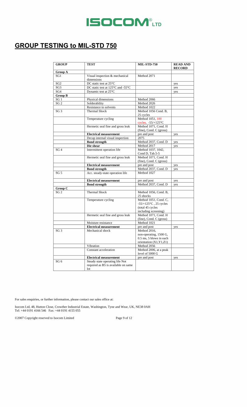
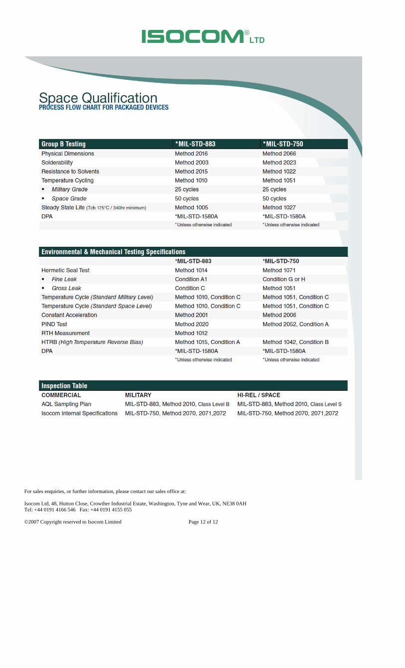
SG2 DC static test at 25°C yes SG3 DC static test at 125°C and ‐55°C yes SG4 Dynamic test at 25°C yes Group B SG 1 Physical dimensions Method 2066 SG 2 Solderability Method 2026 Resistance to solvents Method 1022 SG 3

Thermal Shock Method 1056 Cond. B, 25 cycles

Temperature cycling

Method 1051, 100 cycles, -55/+125°C

Hermetic seal fine and gross leak

Method 1071, Cond. H (fine), Cond. C (gross)

Electrical measurement pre and post yes Decap internal visual inspection 2075 Bond strength Method 2037, Cond. D yes Die shear Method 2017 yes SG 4 Intermittent operation life Method 1037, 1042,

Cond D, Tab.5-5

Hermetic seal fine and gross leak

Method 1071, Cond. H (fine), Cond. C (gross)

Electrical measurement pre and post yes Bond strength Method 2037, Cond. D yes SG 5

Acc. steady‐state operation life Method 1027

Electrical measurement pre and post yes Bond strength Method 2037, Cond. D yes Group C SG 2

Thermal Shock Method 1056, Cond. B, 25 shocks

Temperature cycling

Method 1051, Cond. C, ‐55/+125°C , 25 cycles (total 45 cycles including screening)

Hermetic seal fine and gross leak

Method 1071, Cond. H (fine), Cond. C (gross)

Moisture resistance Method 1021 Electrical measurement pre and post yes SG 3 Mechanical shock Method 2016,

non‐operating, 1500 G, 0.5 ms, 5 blows in each orientation (X1,Y1,Z1)

Vibration Method 2056 Constant acceleration Method 2006, at a peak

level of 5000 G

Electrical measurement pre and post yes SG 6 Steady state operating life Not

required as B5 is available on same lot

ISOCOM®

LTD

For sales enquiries, or further information, please contact our sales office at: Isocom Ltd, 48, Hutton Close, Crowther Industrial Estate, Washington, Tyne and Wear, UK, NE38 0AH Tel: +44 0191 4166 546 Fax: +44 0191 4155 055 ©2007 Copyright reserved to Isocom Limited Page 10 of 12

100% SCREENING to MIL-STD 750

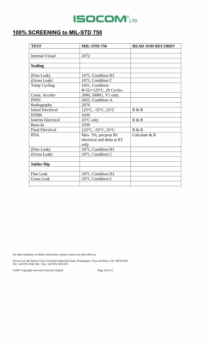
TEST MIL-STD-750 READ AND RECORD? Internal Visual 2072 Sealing (Fine Leak) 1071, Condition H1 (Gross Leak) 1071, Condition C Temp Cycling 1051, Condition

B‐55/+125°C, 20 Cycles.

Const. Acceler 2006, 5000G, Y1 only. PIND 2052, Condition A Radiography 2076 Initial Electrical 125°C, ‐55°C, 25°C R & R HTRB 1039 Interim Electrical 25°C only R & R Burn-In 1039 Final Electrical 125°C, ‐55°C, 25°C R & R PDA Max. 5%, pre/post B1

electrical and delta at RT only

Calculate & R

(Fine Leak) 1071, Condition H1 (Gross Leak) 1071, Condition C Solder Dip Fine Leak 1071, Condition H1 Gross Leak 1071, Condition C

ISOCOM®

LTD

For sales enquiries, or further information, please contact our sales office at: Isocom Ltd, 48, Hutton Close, Crowther Industrial Estate, Washington, Tyne and Wear, UK, NE38 0AH Tel: +44 0191 4166 546 Fax: +44 0191 4155 055 ©2007 Copyright reserved to Isocom Limited Page 11 of 12

ISOCOM®

LTD

For sales enquiries, or further information, please contact our sales office at: Isocom Ltd, 48, Hutton Close, Crowther Industrial Estate, Washington, Tyne and Wear, UK, NE38 0AH Tel: +44 0191 4166 546 Fax: +44 0191 4155 055 ©2007 Copyright reserved to Isocom Limited Page 12 of 12


Recommended