Chap. 7. Dielectric Materials and Insulation - The parallel plate capacitor with free space as an insulator: - The electric dipole moment for a pair of opposite changes +Q and -Q separated by a finite distance a. *Although the net charge is zero, this dipole moment gives rise to an electric field in space and interacts with an electric field from other sources. - The dielectric medium has not only the ability to increase capacitance but also the insulating property (low conductivity) so that the charges are conducted from one plate of the capacitor to the other through the dielectric. *The relative permittivity (dielectric constant) depends on the frequency . - Dielectric breakdown : above the dielectric strength, a large discharge current flows through the dielectric due to insulation failure.
Transcript
Chap. 7. Dielectric Materials and Insulation
- The parallel plate capacitor with free space as an insulator:
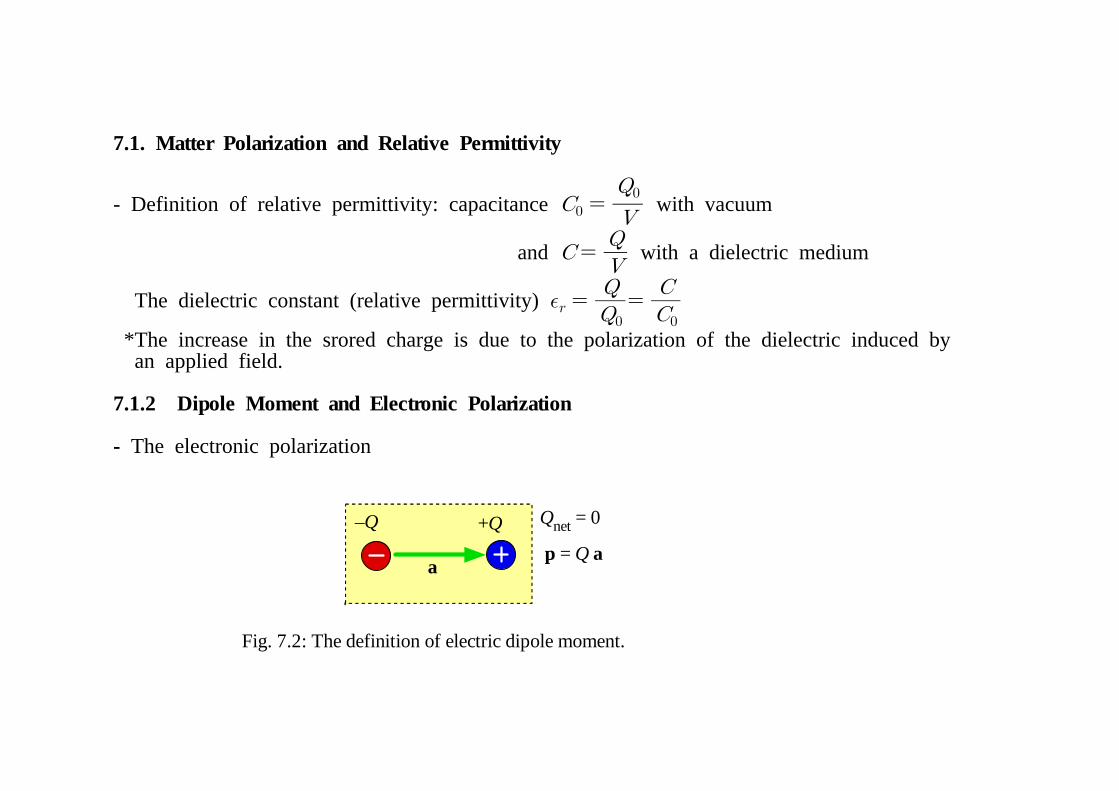
- The electric dipole moment for a pair of opposite changes +Q and -Q separated by a finite distance a. *Although the net charge is zero, this dipole moment gives rise to an electric field in space and interacts with an electric field from other sources.
- The dielectric medium has not only the ability to increase capacitance but also the insulating property (low conductivity) so that the charges are conducted from one plate of the capacitor to the other through the dielectric.
*The relative permittivity (dielectric constant) depends on the frequency.
- Dielectric breakdown: above the dielectric strength, a large discharge current flows through the dielectric due to insulation failure.
+Q–Q
ap = Q a
Qnet = 0
Fig. 7.2: The definition of electric dipole moment.
7.1. Matter Polarization and Relative Permittivity
- Definition of relative permittivity: capacitance with vacuum
and with a dielectric medium
The dielectric constant (relative permittivity)
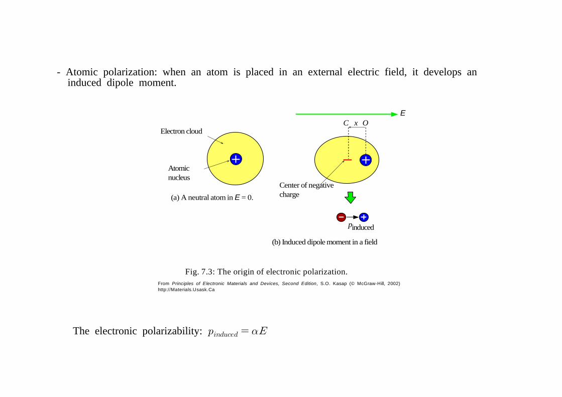
*The increase in the srored charge is due to the polarization of the dielectric induced by an applied field. 7.1.2 Dipole Moment and Electronic Polarization
F ig. 7 .4 : (a ) W hen a d ilec tric is p laced in an elec tric field , bou ndpola riza tion ch arges appear on th e opposite su rfaces. (b ) T he orig inof these pola riza tion ch arges is th e p o la riza tion of the m olecu les ofth e m edium . (c) W e can represen t the w hole d ielectric in term s of itssu rface polariza tion charges + Q P an d -Q P .
7.1.3 Polarization Vector P
- The surface polarization charge :
≡
- In general, the charge per unit area appearing on the surface of a polarized medium is equal to the component of the polarization vector normal to this surface:
- The polarization P induced in a dielectric medium when it is placed in an electric field depends on the field itself: The electric susceptibility
Let the electronic polarizability be → with N = the no. of molecules per unit vol. so
- The field before the insertion of a dielectric medium between two plates:
≡
( free surface charge density)
After the insertion of the dielectric, Using , we have
From the definition
→
Eloc
x
Electric field atatomic scale
E = V/d E
Eloc
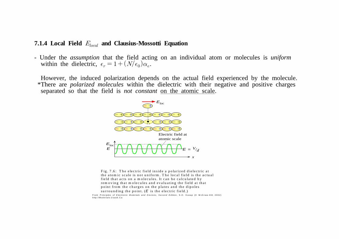
F ig . 7 .6 : T h e e le c tr ic f ie ld in s id e a p o la r iz e d d ie le c tr ic a tth e a to m ic s c a le is n o t u n ifo rm . T h e lo c a l f ie ld is th e a c tu a lf ie ld th a t a c ts o n a m o le c u le s . I t c a n b e c a lc u la te d b yre m o v in g th a t m o le c u le s a n d e v a lu a t in g th e f ie ld a t th a tp o in t f ro m th e c h a rg e s o n th e p la te s a n d th e d ip o le ss u r ro u n d in g th e p o in t . (E is th e e le c t r ic f ie ld .)
- Under the assumption that the field acting on an individual atom or molecules is uniform within the dielectric, .
However, the induced polarization depends on the actual field experienced by the molecule. *There are polarized molecules within the dielectric with their negative and positive charges separated so that the field is not constant on the atomic scale.
- The actual field experienced by a molecules in a dielectric is defined as the local field.
*This local field depends not only on the free charges on the plates but also on the arrangement of all the polarized molecules around a given position (point).
- Evaluation of : 1) remove the molecule at the given point 2) calculate the field at this point coming from all sources, including neighboring polarized molecules
- In the simplest case of a material with a cubic crystal structure, or a liquid (no crystal structure,
Lorentz field
, t hen
From ( ,
the Clausius-Mossotti equation
p+ p–
x
p'+ p'–
E
Cl– Na+
(a)
(b)
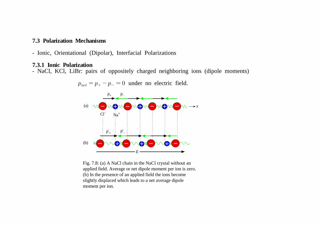
Fig. 7.8: (a) A NaCl chain in the NaCl crystal without anapplied field. Average or net dipole moment per ion is zero.(b) In the presence of an applied field the ions becomeslightly displaced which leads to a net average dipolemoment per ion.
7.3.1 Ionic Polarization - NaCl, KCl, LiBr: pairs of oppositely charged neighboring ions (dipole moments) under no electric field.
- In the presence of the field, ′′≠ : (= ionic polarizability)
( = the no. of ion pairs)
The Clausius-Mossotti equation for ionic polarization
7.3.2 Orientational (Dipolar) Polarization
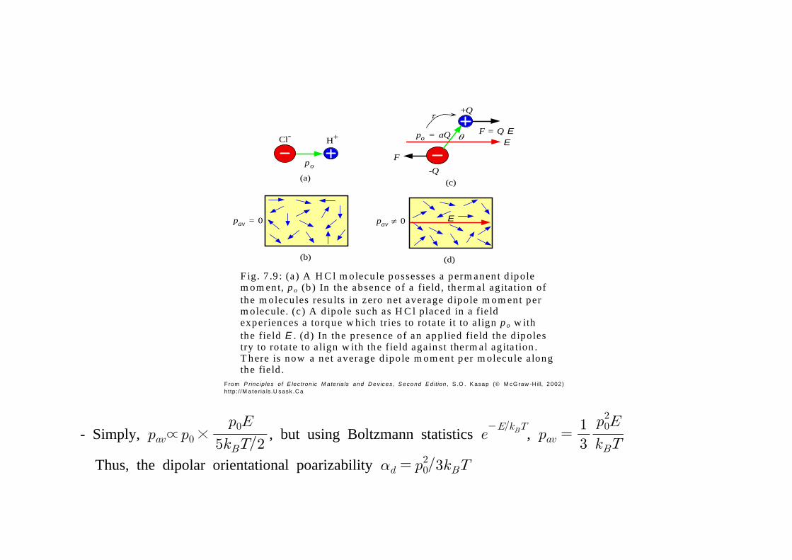
- Molecules with permanent dipole moments: HCl
- For all molecules that align perfectly with the electric field,
- Due to thermal fluctuations, dipole alignment along the electric field will be perturbed (thermal energy ; 5 degrees of freedom) For ≫ , strong dipole alignment with the field For ≪ , no dipole alignment with the field
- The torque experienced by the dipole [See Fig. 7.9c]
where
The max. potential energy
( )
Cl- H+
po
(a)
(b)
pav = 0
θ
+Q
-Q
F = Q E
F
po = aQ
τ
E
pav ≠ 0 E
(c)
(d)
F ig . 7 .9 : (a ) A H C l m olecu le possesses a perm anen t d ipolem om ent, p o (b ) In the absence of a field , therm al agita tion ofthe m olecu les resu lts in zero net average d ipole m om ent perm olecule. (c ) A d ipole such as H C l placed in a fieldexperiences a torque w hich tries to rota te it to a lign p o w iththe field E . (d ) In the p resence of an app lied field the d ipolestry to rota te to a lign w ith the field aga inst therm al agita tion .T here is now a net average d ipole m om ent per m olecu le a longthe field .
- Accumulation of charges at an interface between two materials or between two regions within a material
7.4 Frequency Dependence: Dielectric Constant and Dielectric Loss
- The polarization of the medium under ac conditions leads to an ac dielectric constant that is generally different than the static dielectric constant.
At any instant, where
1) Thermal agitation (fluctuations): randomization of the dipole orientations 2) the molecular rotation in a viscous medium (interactions with neighbors): dipoles can not respond instantaneously to the changes in the applied field.
*If the field changes too rapidly, then the dipoles can not follow the field and thus remain randomly oriented. At high frequencies, → since the field can not induce a dipole moment.
- The polarizability changes from its maximum value to zero as the frequency of the field is increased:
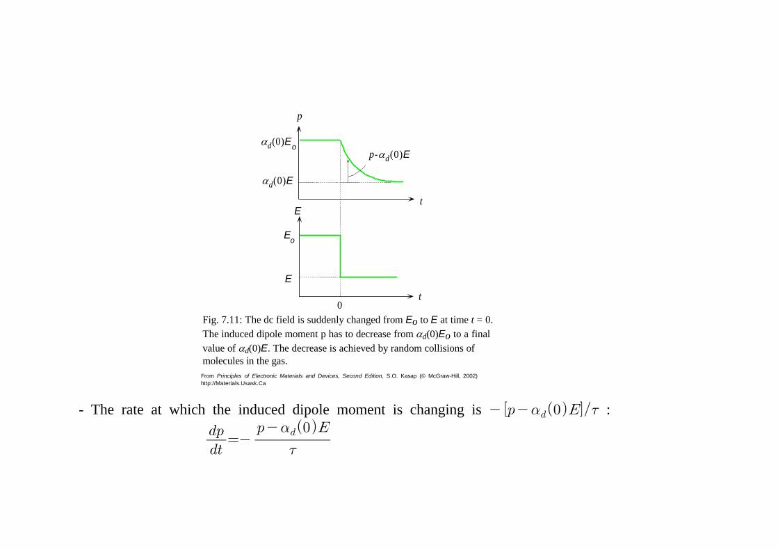
- The field → at time : the induce dipole moment →, relax *The relaxation time = *The relaxation process in the induced dipole moment is achieved by random collisions. The excess dipole moment → →∞
t
E
E
Eo
0
p
t
αd(0)E
p-αd(0)Eαd(0)Eo
Fig. 7.11: The dc field is suddenly changed from Eo to E at time t = 0.The induced dipole moment p has to decrease from αd(0)Eo to a finalvalue of αd(0)E. The decrease is achieved by random collisions ofmolecules in the gas.
- The rate at which the induced dipole moment is changing is :
- For an ac field ,
→ where
; the orientational polarizability
- At low frequencies, ≪ ≈ and p is in phase with E. *The rate of relaxation is much faster than the frequency of the field or the rate at which the polarization is being changed; p then closely follows E.
- At high frequencies, ≫ the rate of relaxation is much slower than the frequency of the field and the polarization p can no longer follow the variations in the field.
- Complex dielectric constant: ′ ′′ The real part ′ decreases from its maximum value ′, corresponding to , to 1 at high frequencies when as →∞.
The imaginary part ′′ is zero at low and high frequencies but peaks at when or when : ′′ represents the energy lost in the dielectric medium as the dipoles are oriented against random collisions by the field.
Fig. 7.14: The frequency dependence of the real and imaginary partsof the dielectric constant in the presence of interfacial, orientational,ionic and electronic polarization mechanisms.
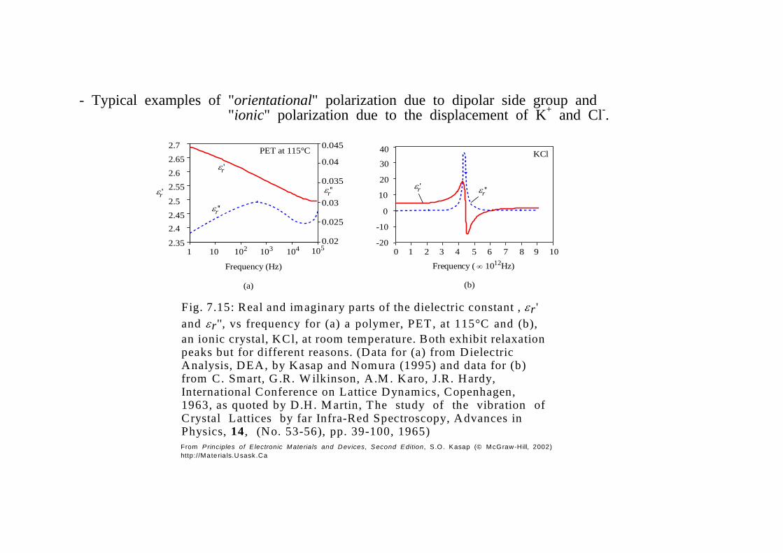
Fig. 7.15: Real and imaginary parts of the dielectric constant , εr 'and εr '', vs frequency for (a) a polymer, PET, at 115°C and (b),an ionic crystal, KCl, at room temperature. Both exhibit relaxationpeaks but for different reasons. (Data for (a) from DielectricAnalysis, DEA, by Kasap and Nomura (1995) and data for (b)from C. Smart, G .R. W ilkinson, A.M . Karo, J.R. Hardy,International Conference on Lattice Dynamics, Copenhagen,1963, as quoted by D.H . M artin, The study of the vibration ofCrystal Lattices by far Infra-Red Spectroscopy, Advances inPhysics, 14 , (No. 53-56), pp. 39-100, 1965)
- Typical examples of "orientational" polarization due to dipolar side group and "ionic" polarization due to the displacement of K+ and Cl-.
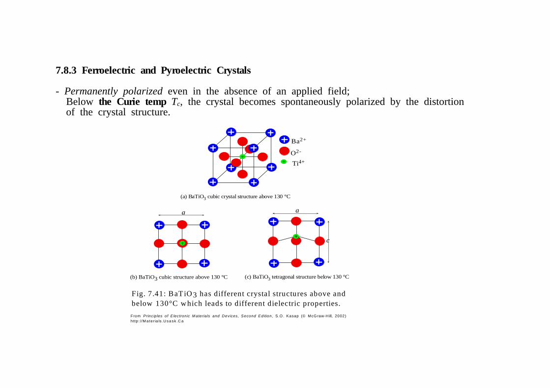
Fig. 7.41: BaT iO 3 has different crystal structures above andbelow 130°C w hich leads to different dielectric properties.
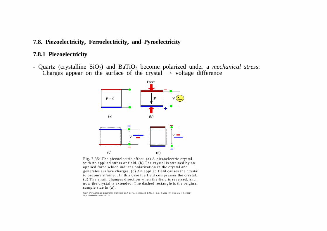
7.8.3 Ferroelectric and Pyroelectric Crystals
- Permanently polarized even in the absence of an applied field; Below the Curie temp Tc, the crystal becomes spontaneously polarized by the distortion of the crystal structure.
Heat
δP δV
Temperature change = δT
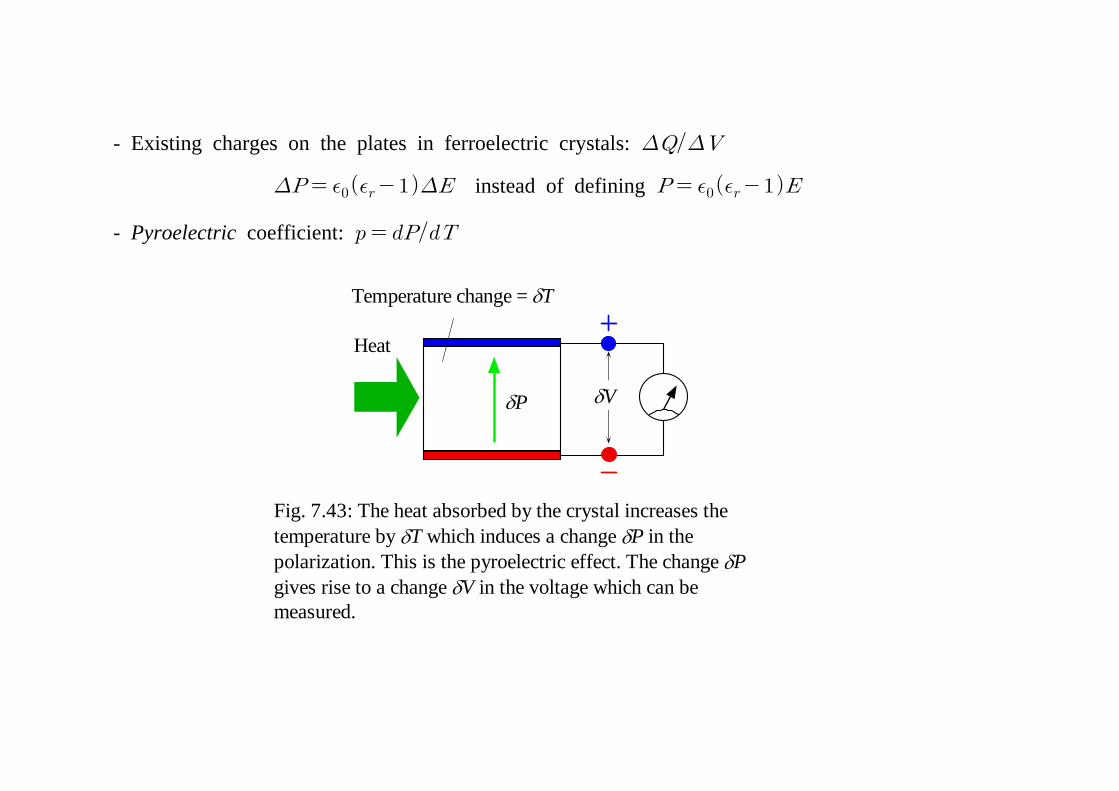
Fig. 7.43: The heat absorbed by the crystal increases thetemperature by δT which induces a change δP in thepolarization. This is the pyroelectric effect. The change δPgives rise to a change δV in the voltage which can bemeasured.
- Existing charges on the plates in ferroelectric crystals:
instead of defining
- Pyroelectric coefficient:
C
+Qfree –Qfree
E
Electrometer
–QP +QP
VDielectric
Co
+Qfree –Qfree
Eo
Electrometer
VacuumVo
(a) (b)
Fig. 7.45: (a) Parallel plate capacitor with free spacebetween plates which has been charged to a voltage Vo.There is no battery to maintain the voltage constant acrossthe capacitor. The electrometer measures the voltagedifference across the plates and, in principle, does no affectthe measurement. (b) After the insertion of the dielectric, thevoltage difference is V, less than Vo and the field in thedielectric is E less than Eo.
7.9 Additional Topics: Electric Displacement & Depolarization Field - Electric Displacement (D) and Free Charges
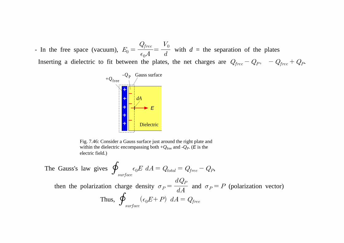
Fig. 7.46: Consider a Gauss surface just around the right plate andwithin the dielectric encompassing both +Qfree and -QP. (E is theelectric field.)
+Qfree-QP
E
Gauss surface
dA
Dielectric
- In the free space (vacuum),
with d = the separation of the plates
Inserting a dielectric to fit between the plates, the net charges are .
The Gauss's law gives
,
then the polarization charge density and (polarization vector)
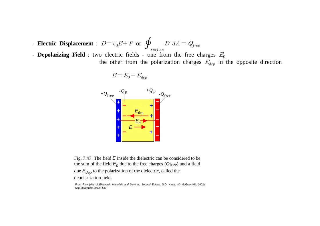
Fig. 7.47: The field E inside the dielectric can be considered to bethe sum of the field E0 due to the free charges (Qfree) and a fielddue Edep to the polarization of the dielectric, called thedepolarization field.
Eo
- Electric Displacement : or
- Depolarizing Field : two electric fields - one from the free charges the other from the polarization charges in the opposite direction
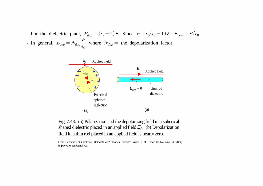
Fig. 7.48: (a) Polarization and the depolarizing field in a sphericalshaped dielectric placed in an applied field E0 . (b) Depolarizationfield in a thin rod placed in an applied field is nearly zero.
- For the dielectric plate, . Since , - In general,