Department of Mechanical Engineering HITEC University Taxila 1 Components of Solar Thermal Systems Components and Subsystems of Solar Thermal Installation Collectors Storage Plan Heat Exchangers Pumps and Expansion Chambers Controller Other Components
Department of Mechanical EngineeringHITEC University Taxila
2
Typical Solar Installations With Main Components
Components of Solar Thermal Systems
Solar Collector mounted on the roofconverts the light that penetrates its glasspanes (short-wave radiation) into heat. Thecollector is therefore the link between thesun and the hot water user
Forced Circulation
Fig. 3.1
image shows a solar heating installationproviding hot water in a house
It is an indirect, closed loop, pumped system
fluid that flows through the collectors is isolatedfrom the potable water, which permits use ofantifreeze and anti-corrosive agents; thesereduce freezing and corrosion problems andtherefore increase the durability and reliability ofthe system.
Department of Mechanical EngineeringHITEC University Taxila
3
Typical Solar Installations With Main Components
Components of Solar Thermal Systems
Forced Circulation—Contd--
Fig. 3.1
As the system has pumped circulation, a largepart of the system, including the tank, can beinstalled inside of the house, with the additionaladvantage of lower thermal loss and increaseddurability
Auxiliary system is installed in series with thepotable water, and as it is an instantaneouswater heater, it achieves higher final output withlower consumption.
In most solar water heating systems – This
configuration is by far the most commonly usedtype of solar thermal systems
Department of Mechanical EngineeringHITEC University Taxila
4
Typical Solar Installations With Main Components
Components of Solar Thermal Systems
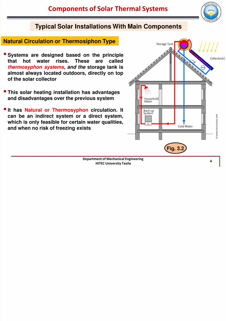
Natural Circulation or Thermosiphon Type
This solar heating installation has advantagesand disadvantages over the previous system
Fig. 3.2
It has Natural or Thermosyphon circulation. It
can be an indirect system or a direct system,which is only feasible for certain water qualities,and when no risk of freezing exists
Systems are designed based on the principlethat hot water rises. These are calledthermosyphon systems , and the storage tank isalmost always located outdoors, directly on top
Department of Mechanical EngineeringHITEC University Taxila
5
Typical Solar Installations With Main Components
Components of Solar Thermal Systems
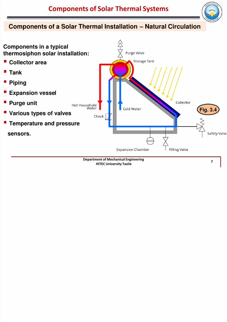
Natural Circulation or Thermosiphon Type
Main advantage: Simpler and cheaper.Main disadvantages: Less integration (and
therefore higher visual impact) as the tank ismounted above the collector, and normallyoutside. Less durable as it is controlled less,with the possibility of over-heating during lowusage and high solar radiation.
Department of Mechanical EngineeringHITEC University Taxila
8
Solar Energy Collectors
Components of Solar Thermal Systems
Solar energy collectors are special kinds of heat exchangers that transform solarradiation energy to internal energy of the transport medium
There are basically two types of solar collectors: non-concentrating or stationary andconcentrating
A non-concentrating collector has the same area for intercepting and absorbing solar
radiation, whereas a sun-tracking concentrating solar collector usually has concavereflecting surfaces to intercept and focus the sun’s beam radiation to a smaller receivingarea, thereby increasing the radiation flux
Department of Mechanical EngineeringHITEC University Taxila
10
Solar Energy Collectors
Components of Solar Thermal Systems
Different definitions of area are used in the manufacturers’ literature to describe the
geometry of the collectorso Gross surface area (collector area) is the product of the exterior length and width of the
collector and defines for example the minimum amount of roof area required formounting.
o Aperture area corresponds to the light entry area of the collector – that is, the areathrough which the solar radiation passes to the collector itself
o COVER / GLAZING : One or moretransparent covers made of glass orplastic that let in solar energy, mostly ofwhich is in visible range and block thelong wavelength thermal radiation
emitted by enclosed heated materials
o ABSORBER : Dark surfaces inside ofhigh absorptivity, called absorber platesthat soak up heat. plate is usually coatedwith a high-absorptance, low-emittancelayer
Department of Mechanical EngineeringHITEC University Taxila
15
Solar Energy Collectors
Components of Solar Thermal Systems
Flat Plate Collectors (FPCs)—contd--
Liquid tubes can be welded to the absorbing plate or they can be an integral part of theplate
Liquid tubes are connected at both ends by large-diameter header tubes
HEADER AND RISER COLLECTOR is the typical design for flat-plate collectors
Alternative is the SERPENTINE DESIGN does not present the potential problem of unevenflow distribution in the various riser tubes of the HEADER AND RISER DESIGN
Department of Mechanical EngineeringHITEC University Taxila
16
Solar Energy Collectors
Components of Solar Thermal Systems
Flat Plate Collectors (FPCs)—contd--
Absorber plate can be a single sheet on which all risers are fixed, or each riser can befixed on a separate fin
Transparent cover is used to reduce convection losses from the absorber plate throughthe restraint of the stagnant air layer between the absorber plate and the glass
Department of Mechanical EngineeringHITEC University Taxila
17
Solar Energy Collectors
Components of Solar Thermal Systems
Flat Plate Collectors (FPCs) — contd--
Transparent cover reduces radiation losses from the collector because the glass istransparent to the shortwave radiation received by the sun, but it is nearly opaque tolongwave thermal radiation emitted by the absorber plate (GREENHOUSE EFFECT).
FPCs are inexpensive to manufacture, theycollect both beam and diffuse radiation
FPCs are permanently fixed in position, so notracking of the sun is required
Optimum tilt angle of the collector is equal to thelatitude of the location, with angle variations of 10°
to 15° more or less, depending on the application For solar cooling the optimum angle is latitude -10°
so that the sun will be perpendicular to thecollector during summertime, when the energy willbe mostly required. For space heating, optimalangle is latitude +10°
Department of Mechanical EngineeringHITEC University Taxila
18
Solar Energy Collectors
Components of Solar Thermal Systems
Flat Plate Collectors (FPCs) — contd--
Collector should also have a long effective life, despite the adverse effects of the sun’s ultraviolet radiation and corrosion and clogging because of acidity, alkalinity, or hardness of the heat transfer fluid, freezing of water, or deposition of dust or moisture on theglazing and breakage of the glazing from thermal expansion, hail, vandalism, or othercauses
Glazing Materials
Requirements for the transparent cover are:
ohigh light transmittance during the whole service life of the collector
o low reflection
o protection from the cooling effects of the wind and convection
o protection from moisture
o stability with regard to mechanical loads (hailstones, broken branches etc.).
Department of Mechanical EngineeringHITEC University Taxila
19
Solar Energy Collectors
Components of Solar Thermal Systems
Flat Plate Collectors (FPCs) — contd--
Glazing Materials—contd--
Glass has been widely used to glaze solar collectors
Glass transmit as much as 90% of the incoming shortwave solar irradiation whiletransmitting virtually none of the longwave radiation emitted outward by the absorberplate
Glass with low iron content has a relatively high transmittance for solar radiation(approximately 0.85 –0.90 at normal incidence), but its transmittance is essentially zero forthe longwave thermal radiation (5.0 –50 μm) emitted by sun-heated surfaces
For direct radiation, transmittance of glass varies considerably with the angle of incidence
Antireflective coatings and surface texture can improve transmission significantly. The
effect of dirt and dust on collector glazing may be quite small
Plastic films and sheets also possess high shortwave transmittance
Most usable varieties also have transmission bands in the middle of the thermal radiationspectrum, they may have long wave transmittances as high as 0.40
Department of Mechanical EngineeringHITEC University Taxila
21
Solar Energy Collectors
ABSORBER — contd--
Components of Solar Thermal Systems
Flat Plate Collectors (FPCs) — contd--
To maximize the energy collection, the absorber of a collector should have a coating thathas high absorptance for solar radiation (short wavelength) and a low emittance for re-radiation (long wavelength) → Such a surface is referred as a SELECTIVE SURFACE
Copper Sheet Black Paint Black Chrome TINOX
By suitable electrolytic or chemical treatment, surfaces can be produced with high valuesof solar radiation absorptance (α) and low values of longwave emittance (ε)
Selective surfaces are particularly important when the collector surface temperature ismuch higher than the ambient air temperature
Department of Mechanical EngineeringHITEC University Taxila
22
Flow passages
Solar Energy Collectors
Components of Solar Thermal Systems
Flat Plate Collectors (FPCs) — contd--
For fluid-heating collectors, passages must be integral with or firmly bonded to theabsorber plate
Materials most frequently used forcollector plates are copper,aluminum, and stainless steel
If the working fluid is a liquid , theflow passage is usually a tube that isattached to or is a part of absorberplate. If the working fluid is air , theflow passage should be below theabsorber plate to minimize heatlosses
Further Details-Self StudyPages: 127-129, PDF: Solar Collectors
Department of Mechanical EngineeringHITEC University Taxila
25
Components of Solar Thermal Systems
Solar Energy Collectors
Flat Plate Collectors (FPCs) — contd – Special Designs
Hybrid Collectors
Hybrid collectors are a combination of solar panels (PV) with liquid based collectors aswell as with air-based collectors
combination with solar panels is reasonable, because during the solar electricityconversion only about 12% (with crystalline silicon) of the solar radiation converts into
electricity, whereas the remainder converts into heat. This heat is used in the hybridcollector to either heat up a liquid or air
The central problem with hybrid collectors is the high and in part more persistenttemperature load of the solar cells in the event of stagnation
Department of Mechanical EngineeringHITEC University Taxila
27
The most commonly studied system is adoubled walled concentric glass tube placed at
the focus of a compound parabolic concentrator
Solar Energy Collectors
Components of Solar Thermal Systems
Compound Parabolic Collectors (CPCs)—Contd--
Fig. 3.14
The absorber can take a variety ofconfigurations. It can be flat, bifacial, wedge,or cylindrical
Compound parabolic collectors should have agap between the receiver and the reflector toprevent the reflector from acting as a finconducting heat away from the absorber
For higher-temperature applications a trackingCPC can be used
Department of Mechanical EngineeringHITEC University Taxila
28
Solar Energy Collectors
Components of Solar Thermal Systems
Compound Parabolic Collectors (CPCs)—Contd--
Compound parabolic collectors can be manufactured either as one unit with one openingand one receiver (see Figure 3.14) or as a panel (see Figure 3.15). When constructed as apanel, the collector looks like a flat-plate collector
Department of Mechanical EngineeringHITEC University Taxila
30
Solar Energy Collectors
Components of Solar Thermal Systems
Vacuum Collectors
Benefits of simple conventional FPCs are greatly reduced when conditions becomeunfavorable during cold, cloudy, and windy days
Weathering influences, such as condensation and moisture, cause early deterioration ofinternal materials, resulting in reduced performance and system failure
To overcome the above mentioned factors and due to the technical difficulties to evacuatethe space between the absorber and cover in FPC and to withstand the resulting externalpressure, evacuated tube collectors are used
In order to completely suppressthermal losses throughconvection, the volume enclosed
in the glass tubes must beevacuated to less than 10 –2 bar (1kPa)
Additional evacuation (up to 10-6 bar) prevents losses throughthermal conduction
Department of Mechanical EngineeringHITEC University Taxila
31
Radiation losses cannot be reduced by creating a vacuum, as no medium is necessary forthe transport of radiation. They are kept low, as in the case of glazed flat-plate collectors,by selective coatings (small ε-value).
Solar Energy Collectors
Components of Solar Thermal Systems
Vacuum Collectors—contd--
absorber is installed as either flat or upward-vaulted metal strips or as a coating applied toan internal glass bulb in an evacuated glass tube
An evacuated tube collector consists of a number oftubes that are connected together and which arelinked at the top by an insulated distributor orcollector box, in which the feed or return lines run.
There are two main sorts of evacuated tube collector:the Direct Flow-through Type and the Heat-pipe Type.
Department of Mechanical EngineeringHITEC University Taxila
32
b) Absorber: flat, metal with coating. Passage: metal U-pipe
a) Absorber: flat, metal with coating. Passage: metal coaxial pipe
Glass
Absorber
Glass
Absorber
Glass
Absorber
c) Absorber: flat, metal with coating. Passage: metal, circular pipe straight through g) Absorber: cylindrical, metal with coating. Passage: metal U-pipe
Glass
Absorber
f) Absorber: cylindrical, glass with coating. Passage:
glass coaxial pipe
Glass
Absorber
e) Absorber: cylindrical, glass with coating. Passage: glass
Glass
Absorber
Schematic diagrams of different configurations of directflow type evacuated tube collectors
Department of Mechanical EngineeringHITEC University Taxila
35
Solar Energy Collectors
Components of Solar Thermal Systems
Vacuum Collectors—contd--
Heat-pipe Evacuated Tube Collectors
Heat pipe is an isothermal devise purely based on evaporation and condensation cycle ofthe working fluid
A selectively coated absorber strip, which ismetallically bonded to a heat pipe, isplugged into the evacuated glass tube
heat pipe is filled with alcohol or water in avacuum, which evaporates at temperaturesas low as 25°C
The vapor thus occurring rises upwards
At the upper end of the heat pipe the heatreleased by condensation of the vapor istransferred via a heat exchanger (condenser)to the heat transfer medium as it flows by Fig. 3.18
Department of Mechanical EngineeringHITEC University Taxila
39
Solar Energy Collectors
Components of Solar Thermal Systems
Stagnation temperature
Stagnation Temperature is the temperature at a stagnation point in a fluid flow
oIf the circulation pump fails in the event of strong solar irradiance,
oAbsorber heats up until the heat losses through convection, heat radiation and heatconduction reach the thermal output of the absorber
oor if – for example in holiday times – no hot water is used so that the store is hot (60 –90°C; 140 –194°F) and the system switches off, no more heat is drawn from thecollector
Well-insulated Glazed Flat-plate Collectors achieve maximum stagnation temperatures of160 –200°C (320 –392°F) --- Evacuated Tube Collectors 200 –300°C (392 –572°F) or with areflector – as much as 350°C (662°F)
For Solar collectors STAGNATION CONDITIONS are considered to be any situation underwhich the solar collector can not adequately reject absorbed solar heat to its primaryheat transfer fluid, thereby resulting in the solar collector and/or its components(including the heat-transfer fluid contained within its flow passages) to increase in
Department of Mechanical EngineeringHITEC University Taxila
40
Such extreme stagnation conditions lead to:o deterioration of collector materials, like loss of vacuum in ETCs (evacuated tube
collectors) de to out-gassing from collector materials,oheat transfer fluid may rapidly degrade or even boil,oexcessive pressures may occur in the solar collector heat-transfer loop
Solar Energy Collectors
Components of Solar Thermal Systems
Stagnation temperature—contd--
Heat Storage
Energy storage in solar thermal applications is necessary, whenever there is mismatchbetween the available solar radiation and demand---Because of the seasonal, diurnal andintermittent nature of solar radiation
Optimum capacity of an storage system depends on:
o the expected time dependence of solar radiation availabilityo the nature of loads to be expected on the processo The manner in which auxiliary energy suppliedo An Economic analysis that determines how much of the load should be carried by
Department of Mechanical EngineeringHITEC University Taxila
42
Components of Solar Thermal Systems
Heat Storage
Types of Thermal Energy Storage
Sensible-Heat Storage
Sensible heat Q is stored in a material of mass m and specific heat C p by rising thetemperature of the storage material from T 1 to T 2 and is :
2
1
2
1
T T
T
p
T
p dT VcdT mcQ
Most Common sensible heat storage materials are water, organic oils, rocks, ceramics,and molten salt----Water has the highest specific heat value of 4190 J/kg. C
Most common medium for storing sensibleheat for use with low and mediumtemperature solar systems is Water---it’s cheap and abundant
Water is the standard storage medium for solar-heating and cooling systems for buildingstoday
Department of Mechanical EngineeringHITEC University Taxila 48
Components of Solar Thermal Systems
Heat Storage
Types of Thermal Energy Storage—contd--
Sensible-Heat Storage—contd-- Narrowness of the Hot Water Store
As soon as hot water is drawn off, cold water flows in: thisshould not mix with the hot water. The slimmer and taller thestore, the more pronounced the temperature stratification will be
Upright stores have the best stratification; the recommendedheight –diameter ratio for optimum stratification is at least 2.5:1
Coldest possible lower zone ensuresthat, even with low irradiance, the solarsystem can still operate with highefficiency at a low temperature level
Stable Stratification
No stratification, Additional Heat Required
For interested readers:1- Chapter-8, Energy Storage, Book: by
Duffie and Beckmann2- Chapter-2, Book: Planning and