36
CHAPTER 1 EXERGY: A MEASURE OF WORK POTENTIAL
| Date post: | 30-Nov-2015 |
| Category: |
Documents |
| Upload: | hanis-kamaruddin |
| View: | 78 times |
| Download: | 7 times |
CHAPTER 1
EXERGY: A MEASURE OF WORK POTENTIAL
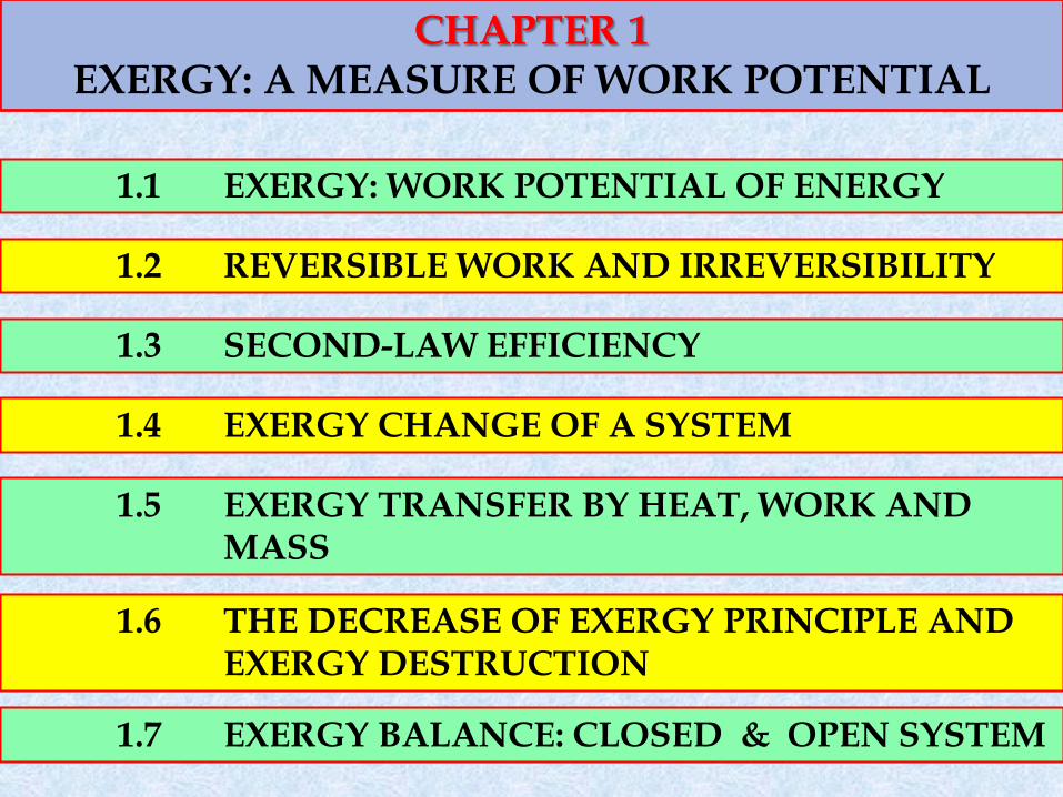
CHAPTER 1 EXERGY: A MEASURE OF WORK POTENTIAL
1.1 EXERGY: WORK POTENTIAL OF ENERGY
1.2 REVERSIBLE WORK AND IRREVERSIBILITY
1.3 SECOND-LAW EFFICIENCY
1.4 EXERGY CHANGE OF A SYSTEM
1.5 EXERGY TRANSFER BY HEAT, WORK AND MASS
1.6 THE DECREASE OF EXERGY PRINCIPLE AND EXERGY DESTRUCTION
1.7 EXERGY BALANCE: CLOSED & OPEN SYSTEM
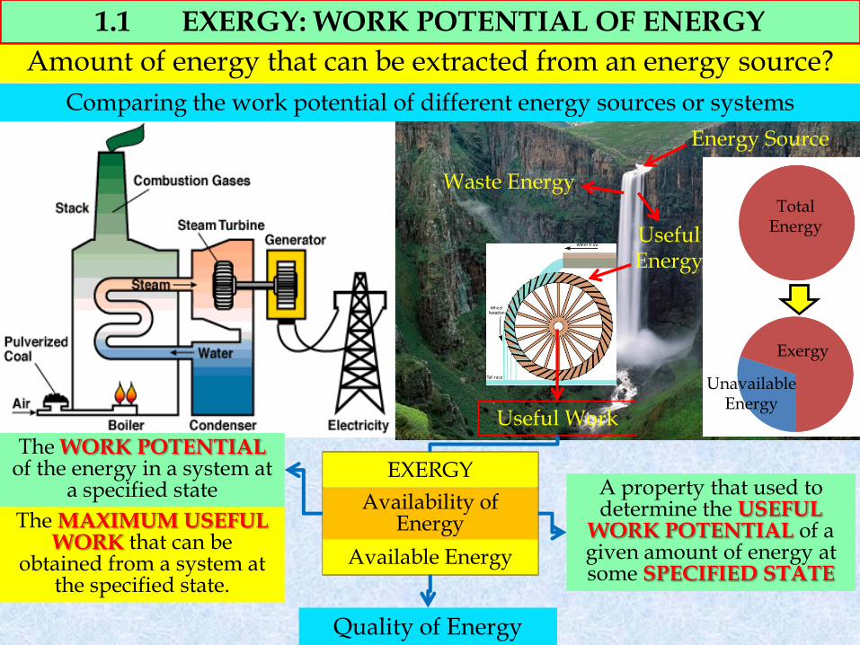
Energy Source
Waste Energy
Useful Energy
Useful Work
Availability of Energy
Available Energy
A property that used to determine the USEFUL
WORK POTENTIAL of a given amount of energy at some SPECIFIED STATE
The MAXIMUM USEFUL WORK that can be
obtained from a system at the specified state.
Total Energy
Exergy
Unavailable Energy
1.1 EXERGY: WORK POTENTIAL OF ENERGY
Quality of Energy
Comparing the work potential of different energy sources or systems
Amount of energy that can be extracted from an energy source?
EXERGY The WORK POTENTIAL
of the energy in a system at a specified state
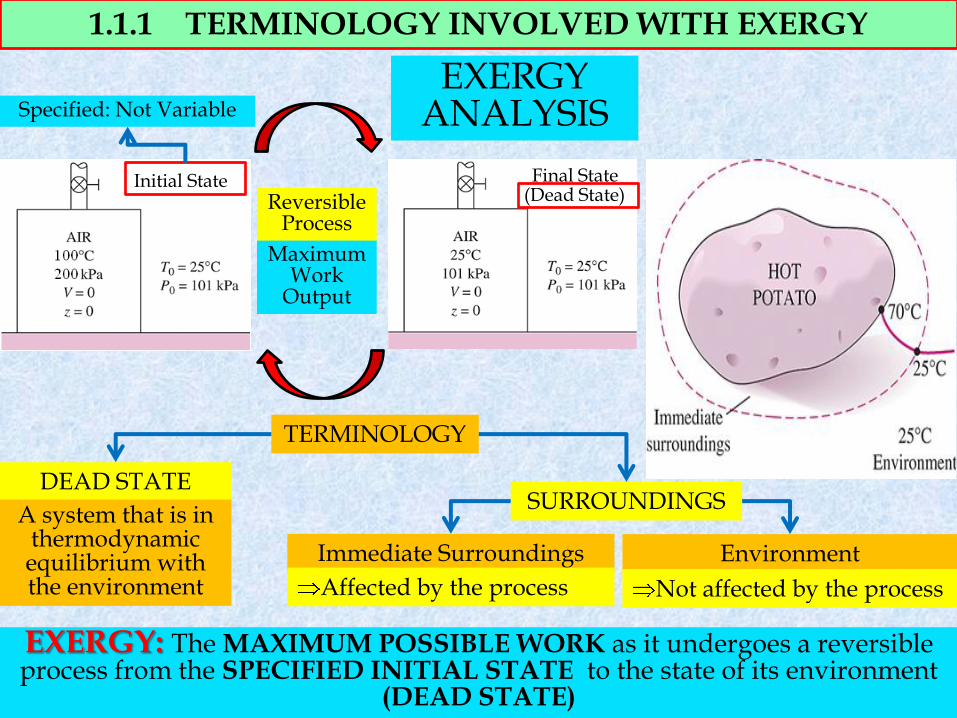
1.1.1 TERMINOLOGY INVOLVED WITH EXERGY
EXERGY: The MAXIMUM POSSIBLE WORK as it undergoes a reversible process from the SPECIFIED INITIAL STATE to the state of its environment
(DEAD STATE)
TERMINOLOGY
DEAD STATE SURROUNDINGS
Immediate Surroundings Environment
Affected by the process Not affected by the process
A system that is in thermodynamic equilibrium with the environment
Initial State Final State (Dead State)
EXERGY ANALYSIS Specified: Not Variable
Maximum Work
Output
Reversible Process
100% ENERGY
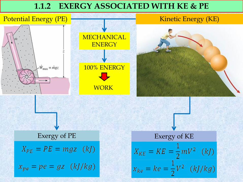
1.1.2 EXERGY ASSOCIATED WITH KE & PE
Kinetic Energy (KE)
MECHANICAL ENERGY
Potential Energy (PE)
WORK
Exergy of KE Exergy of PE
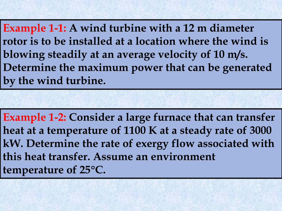
Example 1-1: A wind turbine with a 12 m diameter rotor is to be installed at a location where the wind is blowing steadily at an average velocity of 10 m/s. Determine the maximum power that can be generated by the wind turbine.
Example 1-2: Consider a large furnace that can transfer heat at a temperature of 1100 K at a steady rate of 3000 kW. Determine the rate of exergy flow associated with this heat transfer. Assume an environment temperature of 25 C.
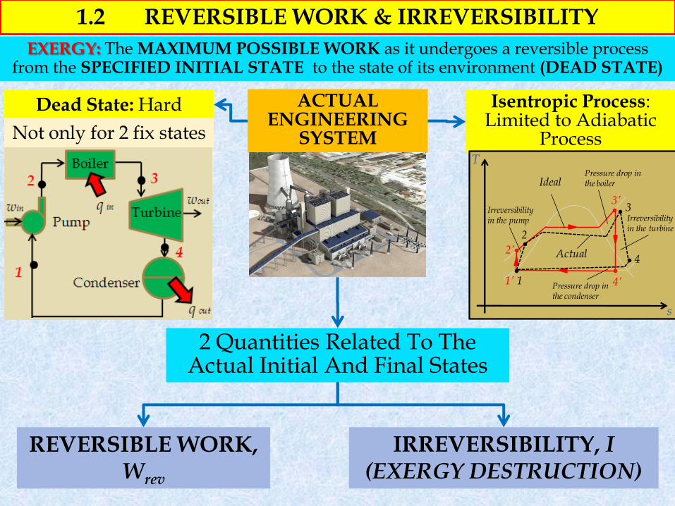
1.2 REVERSIBLE WORK & IRREVERSIBILITY
2 Quantities Related To The Actual Initial And Final States
ACTUAL ENGINEERING
SYSTEM
Dead State: Hard
REVERSIBLE WORK, Wrev
IRREVERSIBILITY, I (EXERGY DESTRUCTION)
Isentropic Process: Limited to Adiabatic
Process Not only for 2 fix states
EXERGY: The MAXIMUM POSSIBLE WORK as it undergoes a reversible process from the SPECIFIED INITIAL STATE to the state of its environment (DEAD STATE)
T
s
1’
2’
3’
4’1
2
3
4
Ideal
Actual
Pressure drop in the boiler
Irreversibility in the turbine
Irreversibility in the pump
Pressure drop in the condenser
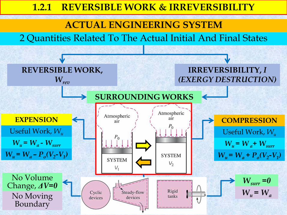
1.2.1 REVERSIBLE WORK & IRREVERSIBILITY
2 Quantities Related To The Actual Initial And Final States
ACTUAL ENGINEERING SYSTEM
REVERSIBLE WORK, Wrev
IRREVERSIBILITY, I (EXERGY DESTRUCTION)
COMPRESSION EXPENSION
Useful Work, Wu
Wu = W a+ Wsurr
Wu = Wa + Po(V2-V1)
Useful Work, Wu
Wu = Wa - Wsurr
Wu = Wa – Po(V2-V1)
Wsurr =0
SURROUNDING WORKS
No Volume Change, ΔV=0
No Moving Boundary
Wu = Wa
T
s
1’
2’
3’
4’1
2
3
4
Ideal
Actual
Pressure drop in the boiler
Irreversibility in the turbine
Irreversibility in the pump
Pressure drop in the condenser
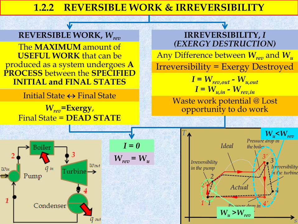
1.2.2 REVERSIBLE WORK & IRREVERSIBILITY
REVERSIBLE WORK, Wrev IRREVERSIBILITY, I (EXERGY DESTRUCTION) The MAXIMUM amount of
USEFUL WORK that can be produced as a system undergoes A PROCESS between the SPECIFIED
INITIAL and FINAL STATES
Initial State Final State
Wrev=Exergy, Final State = DEAD STATE
Any Difference between Wrev and Wu
Irreversibility = Exergy Destroyed
I = Wrev,out - Wu,out I = Wu,in - Wrev,in
Waste work potential @ Lost opportunity to do work
I = 0
Wrev = Wu
Wu >Wrev
Wu<Wrev
Example 1-3: A heat engine receives heat from a source at 1200 K at a rate of 500 kJ/s and rejects the waste heat to a medium at 300 K. The power output of the heat engine is 180 kW. Determine the reversible power and the irreversibility rate for this process.
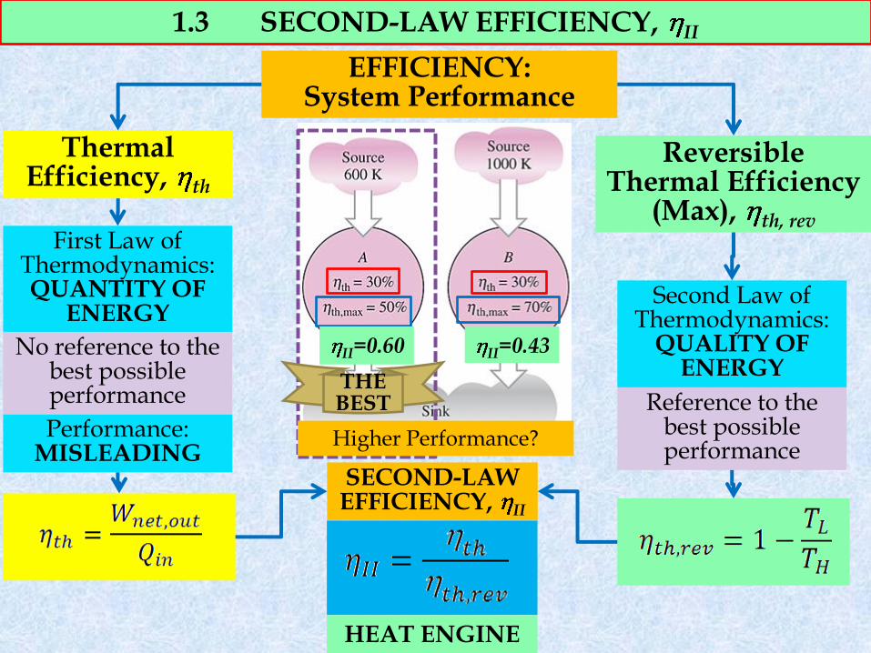
1.3 SECOND-LAW EFFICIENCY, II
Reversible Thermal Efficiency
(Max), th, rev
EFFICIENCY: System Performance
Thermal Efficiency, th
First Law of Thermodynamics: QUANTITY OF
ENERGY
Performance: MISLEADING
No reference to the best possible performance
Second Law of Thermodynamics:
QUALITY OF ENERGY
Reference to the best possible performance
SECOND-LAW EFFICIENCY, II
THE BEST
HEAT ENGINE
Higher Performance?
II=0.60 II=0.43
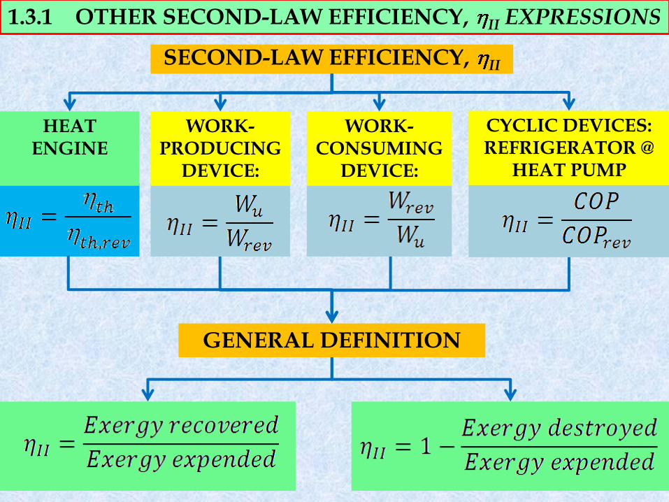
1.3.1 OTHER SECOND-LAW EFFICIENCY, II EXPRESSIONS
WORK-PRODUCING
DEVICE:
WORK-CONSUMING
DEVICE:
GENERAL DEFINITION
CYCLIC DEVICES: REFRIGERATOR @
HEAT PUMP
SECOND-LAW EFFICIENCY, II
HEAT ENGINE
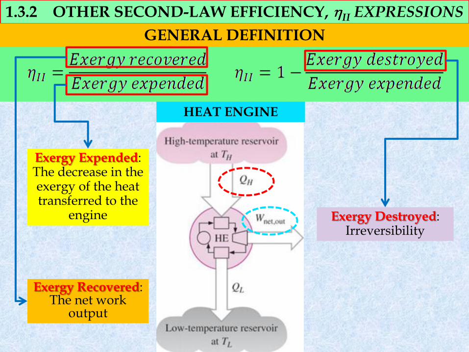
1.3.2 OTHER SECOND-LAW EFFICIENCY, II EXPRESSIONS
GENERAL DEFINITION
Exergy Expended: The decrease in the exergy of the heat transferred to the
engine
Exergy Recovered: The net work
output
HEAT ENGINE
Exergy Destroyed: Irreversibility
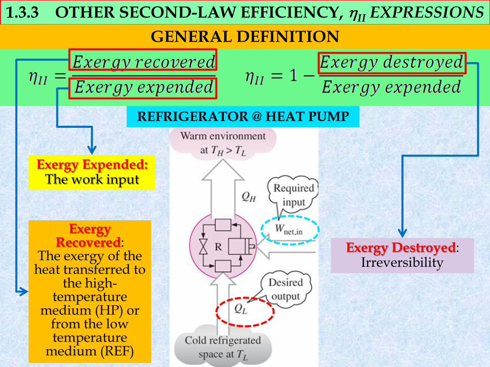
1.3.3 OTHER SECOND-LAW EFFICIENCY, II EXPRESSIONS
Exergy Expended: The work input
Exergy Recovered:
The exergy of the heat transferred to
the high-temperature
medium (HP) or from the low temperature
medium (REF)
GENERAL DEFINITION
REFRIGERATOR @ HEAT PUMP
Exergy Destroyed: Irreversibility
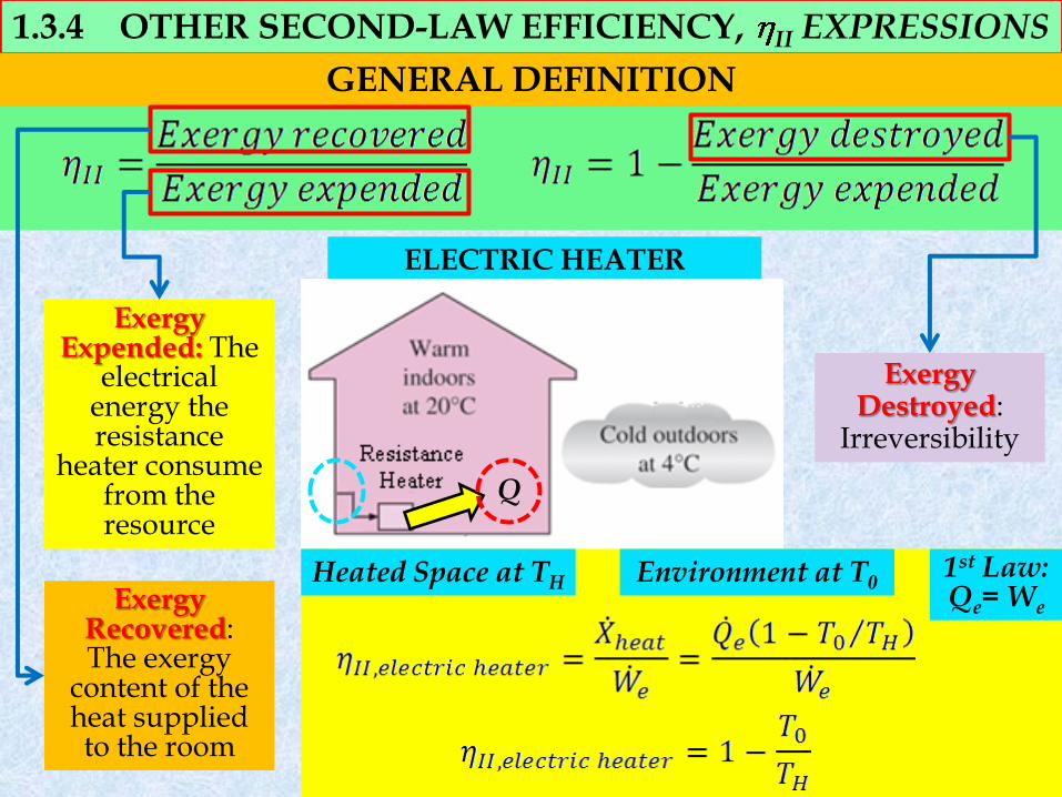
1.3.4 OTHER SECOND-LAW EFFICIENCY, II EXPRESSIONS
ELECTRIC HEATER
Exergy Expended: The
electrical energy the resistance
heater consume from the resource
Exergy Recovered: The exergy
content of the heat supplied to the room
GENERAL DEFINITION
Exergy Destroyed:
Irreversibility
Q
Heated Space at TH Environment at T0 1st Law: Qe= We
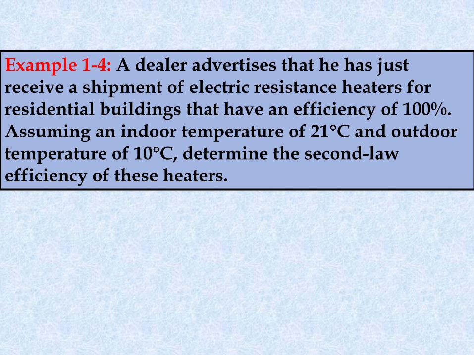
Example 1-4: A dealer advertises that he has just receive a shipment of electric resistance heaters for residential buildings that have an efficiency of 100%. Assuming an indoor temperature of 21 C and outdoor temperature of 10 C, determine the second-law efficiency of these heaters.
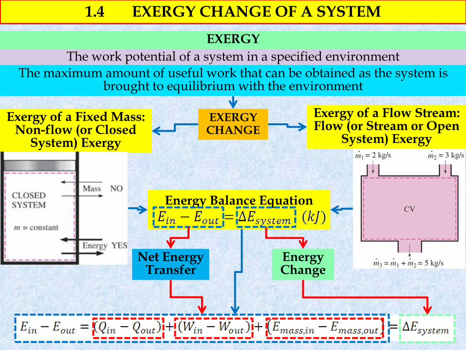
1.4 EXERGY CHANGE OF A SYSTEM
The work potential of a system in a specified environment
The maximum amount of useful work that can be obtained as the system is brought to equilibrium with the environment
EXERGY
EXERGY CHANGE
Exergy of a Fixed Mass: Non-flow (or Closed
System) Exergy
Exergy of a Flow Stream: Flow (or Stream or Open
System) Exergy
Energy Balance Equation
Energy Change
Net Energy Transfer
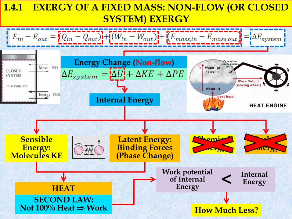
1.4.1 EXERGY OF A FIXED MASS: NON-FLOW (OR CLOSED SYSTEM) EXERGY
Energy Change (Non-flow)
Internal Energy
Sensible Energy:
Molecules KE
Latent Energy: Binding Forces (Phase Change)
Chemical Energy
Nuclear Energy
HEAT
SECOND LAW: Not 100% Heat Work
Work potential of Internal
Energy
How Much Less?
< Internal Energy
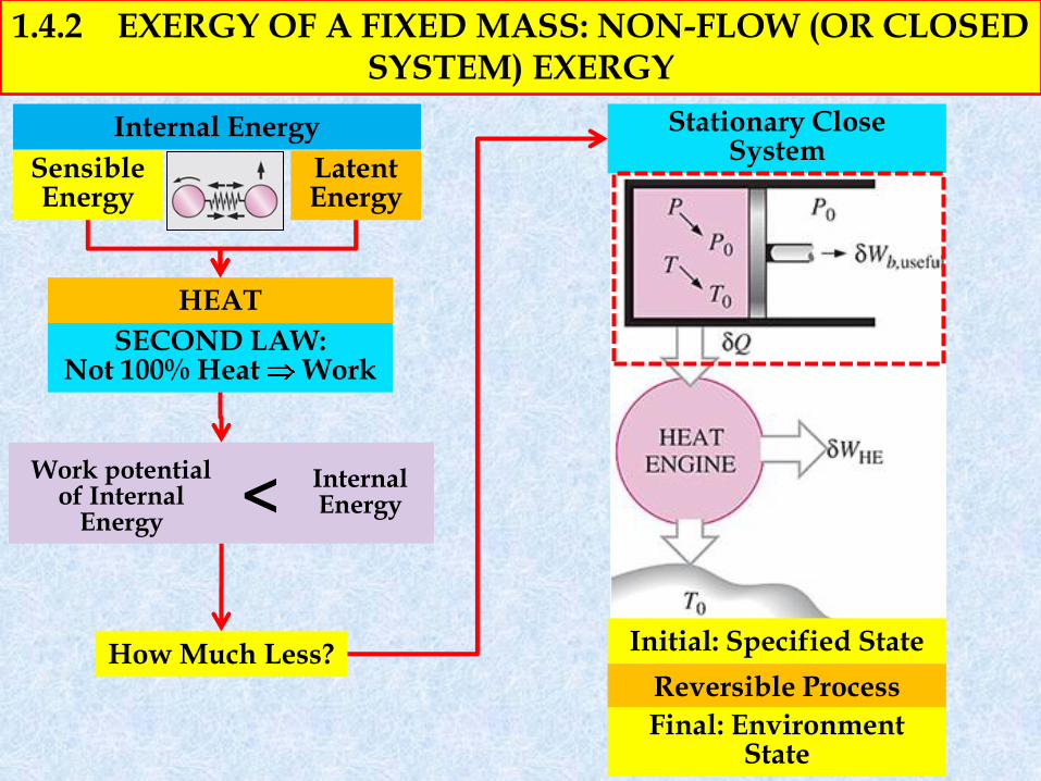
1.4.2 EXERGY OF A FIXED MASS: NON-FLOW (OR CLOSED SYSTEM) EXERGY
Stationary Close System
Internal Energy
Sensible Energy
Latent Energy
HEAT
SECOND LAW: Not 100% Heat Work
Work potential of Internal
Energy
How Much Less?
< Internal Energy
Initial: Specified State
Reversible Process
Final: Environment State
Reversible Heat Engine: T T0
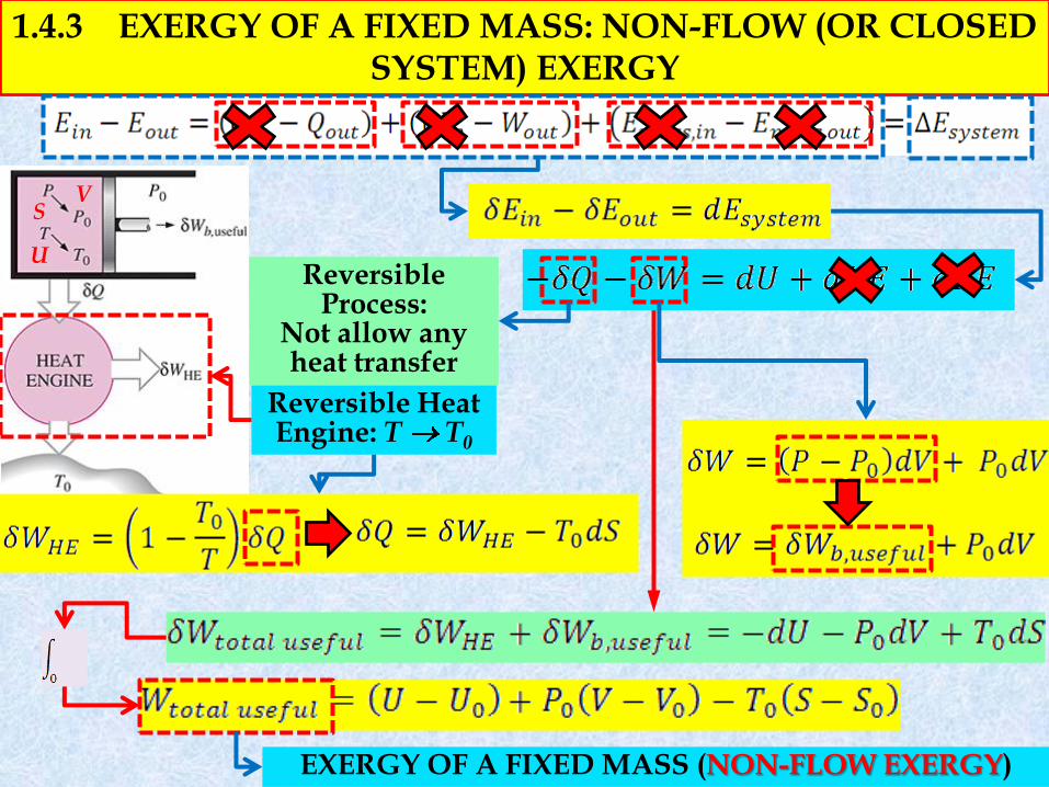
1.4.3 EXERGY OF A FIXED MASS: NON-FLOW (OR CLOSED SYSTEM) EXERGY
V
U
S
Reversible Process:
Not allow any heat transfer
EXERGY OF A FIXED MASS (NON-FLOW EXERGY)
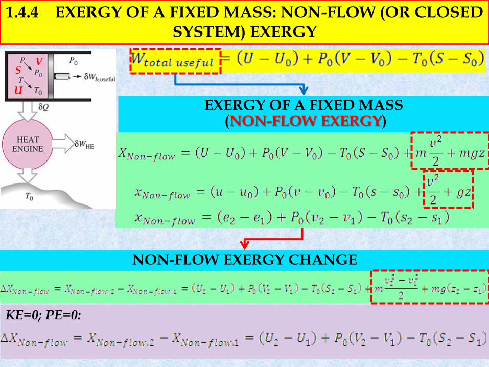
KE=0; PE=0:
1.4.4 EXERGY OF A FIXED MASS: NON-FLOW (OR CLOSED SYSTEM) EXERGY
NON-FLOW EXERGY CHANGE
V
U
S
EXERGY OF A FIXED MASS (NON-FLOW EXERGY)
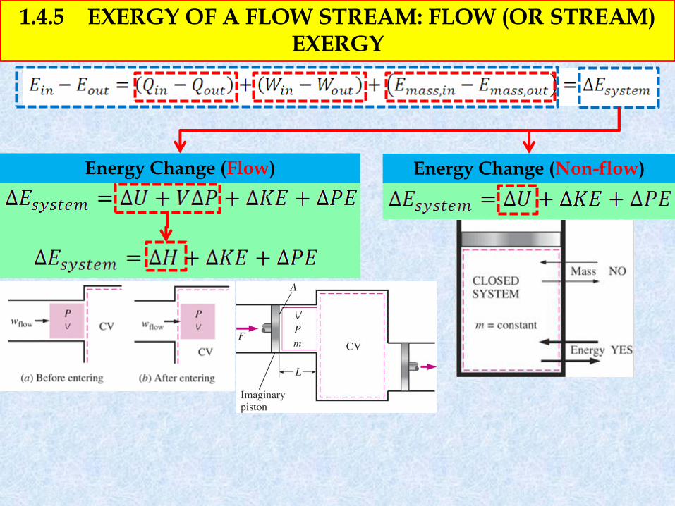
1.4.5 EXERGY OF A FLOW STREAM: FLOW (OR STREAM) EXERGY
Energy Change (Non-flow) Energy Change (Flow)
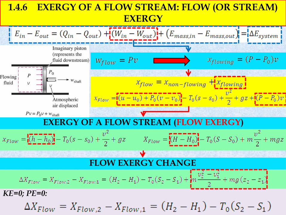
KE=0; PE=0:
1.4.6 EXERGY OF A FLOW STREAM: FLOW (OR STREAM) EXERGY
FLOW EXERGY CHANGE
EXERGY OF A FLOW STREAM (FLOW EXERGY)
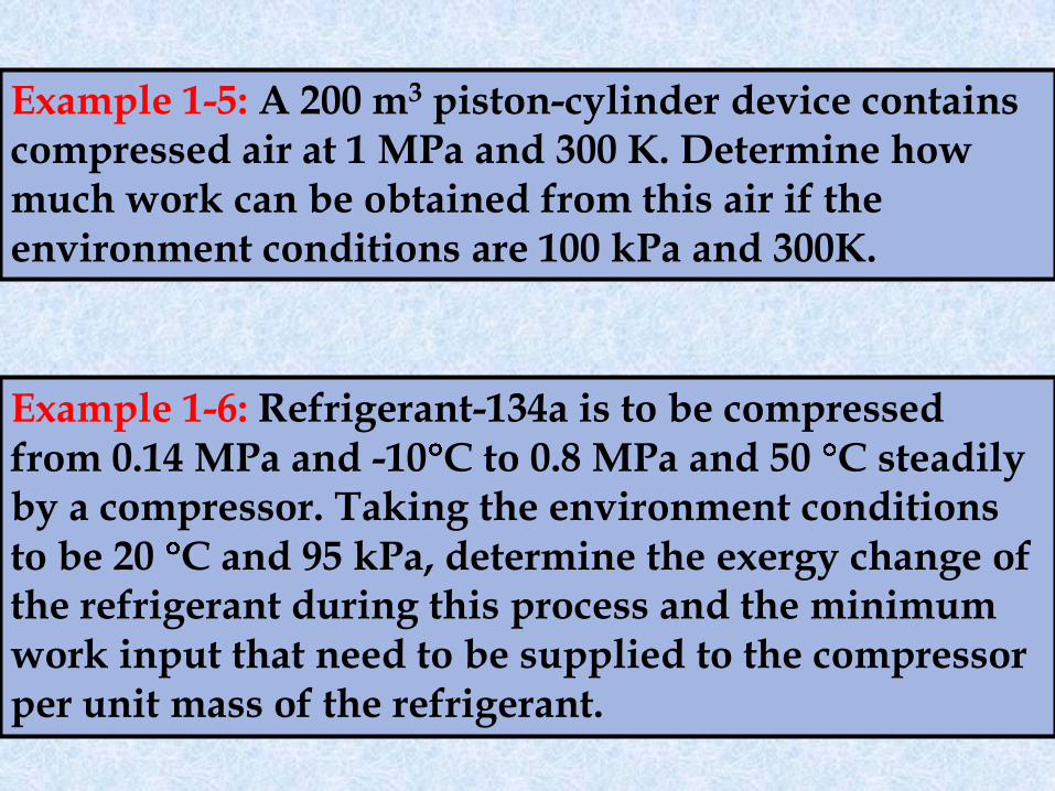
Example 1-5: A 200 m3 piston-cylinder device contains compressed air at 1 MPa and 300 K. Determine how much work can be obtained from this air if the environment conditions are 100 kPa and 300K.
Example 1-6: Refrigerant-134a is to be compressed from 0.14 MPa and -10 C to 0.8 MPa and 50 C steadily by a compressor. Taking the environment conditions to be 20 C and 95 kPa, determine the exergy change of the refrigerant during this process and the minimum work input that need to be supplied to the compressor per unit mass of the refrigerant.
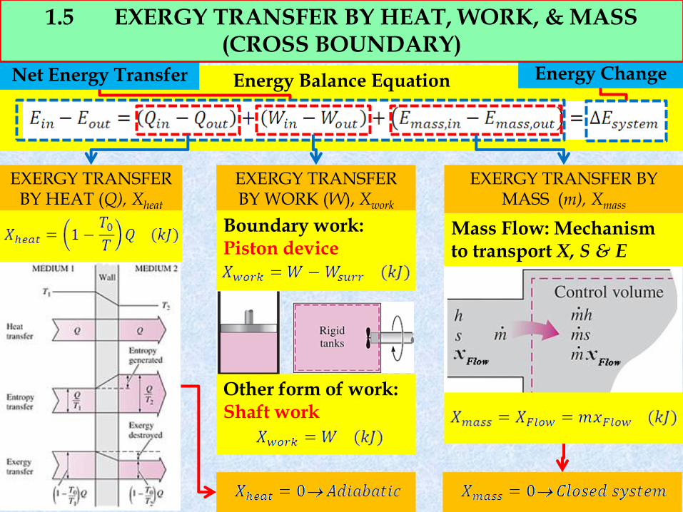
Energy Balance Equation
Energy Change Net Energy Transfer
EXERGY TRANSFER BY HEAT (Q), Xheat
EXERGY TRANSFER BY WORK (W), Xwork
EXERGY TRANSFER BY MASS (m), Xmass
Boundary work: Piston device
Other form of work: Shaft work
1.5 EXERGY TRANSFER BY HEAT, WORK, & MASS (CROSS BOUNDARY)
Mass Flow: Mechanism to transport X, S & E
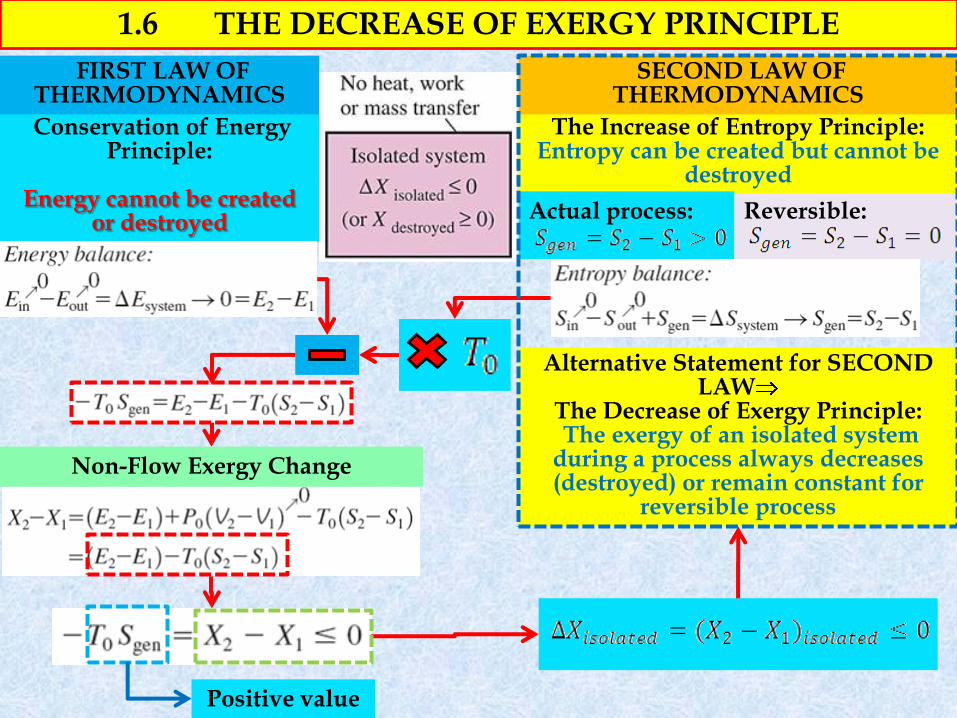
Reversible:
Conservation of Energy Principle:
Energy cannot be created
or destroyed
The Increase of Entropy Principle: Entropy can be created but cannot be
destroyed
FIRST LAW OF THERMODYNAMICS
SECOND LAW OF THERMODYNAMICS
Actual process:
Alternative Statement for SECOND LAW
The Decrease of Exergy Principle: The exergy of an isolated system during a process always decreases (destroyed) or remain constant for
reversible process
1.6 THE DECREASE OF EXERGY PRINCIPLE
Positive value
Non-Flow Exergy Change
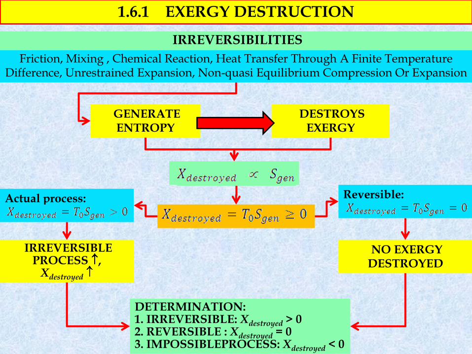
GENERATE ENTROPY
Friction, Mixing , Chemical Reaction, Heat Transfer Through A Finite Temperature Difference, Unrestrained Expansion, Non-quasi Equilibrium Compression Or Expansion
1.6.1 EXERGY DESTRUCTION
DESTROYS EXERGY
Reversible:
Actual process:
IRREVERSIBLE PROCESS ,
Xdestroyed
NO EXERGY DESTROYED
DETERMINATION: 1. IRREVERSIBLE: Xdestroyed > 0 2. REVERSIBLE : Xdestroyed = 0 3. IMPOSSIBLEPROCESS: Xdestroyed < 0
IRREVERSIBILITIES
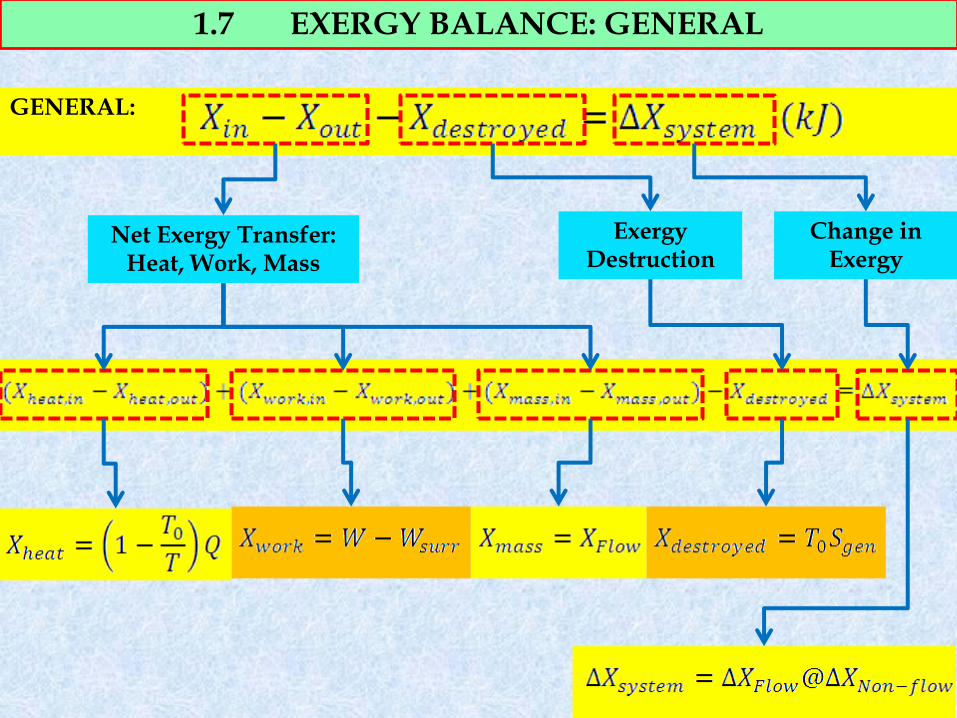
1.7 EXERGY BALANCE: GENERAL
GENERAL:
Net Exergy Transfer: Heat, Work, Mass
Exergy Destruction
Change in Exergy
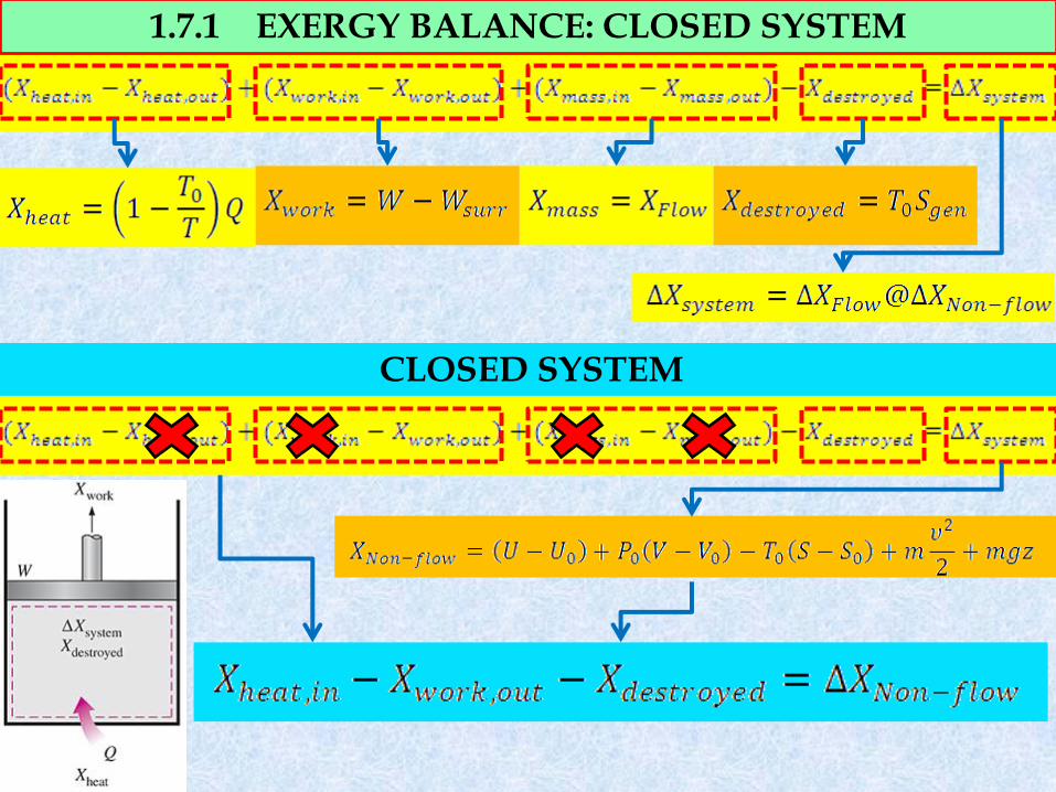
1.7.1 EXERGY BALANCE: CLOSED SYSTEM
CLOSED SYSTEM
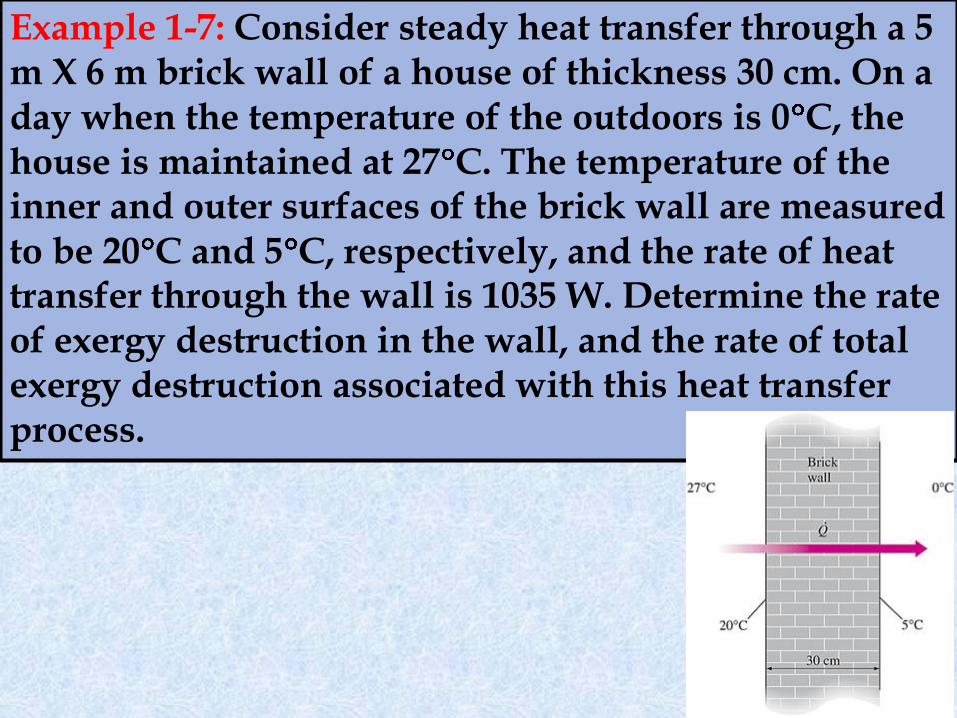
Example 1-7: Consider steady heat transfer through a 5 m X 6 m brick wall of a house of thickness 30 cm. On a day when the temperature of the outdoors is 0 C, the house is maintained at 27 C. The temperature of the inner and outer surfaces of the brick wall are measured to be 20 C and 5 C, respectively, and the rate of heat transfer through the wall is 1035 W. Determine the rate of exergy destruction in the wall, and the rate of total exergy destruction associated with this heat transfer process.
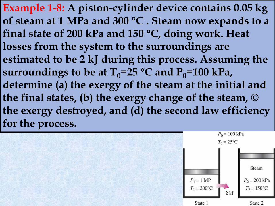
Example 1-8: A piston-cylinder device contains 0.05 kg of steam at 1 MPa and 300 C . Steam now expands to a final state of 200 kPa and 150 C, doing work. Heat losses from the system to the surroundings are estimated to be 2 kJ during this process. Assuming the surroundings to be at T0=25 C and P0=100 kPa, determine (a) the exergy of the steam at the initial and the final states, (b) the exergy change of the steam, © the exergy destroyed, and (d) the second law efficiency for the process.
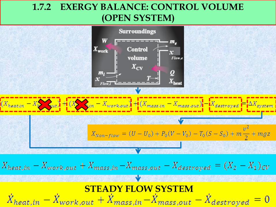
1.7.2 EXERGY BALANCE: CONTROL VOLUME (OPEN SYSTEM)
STEADY FLOW SYSTEM
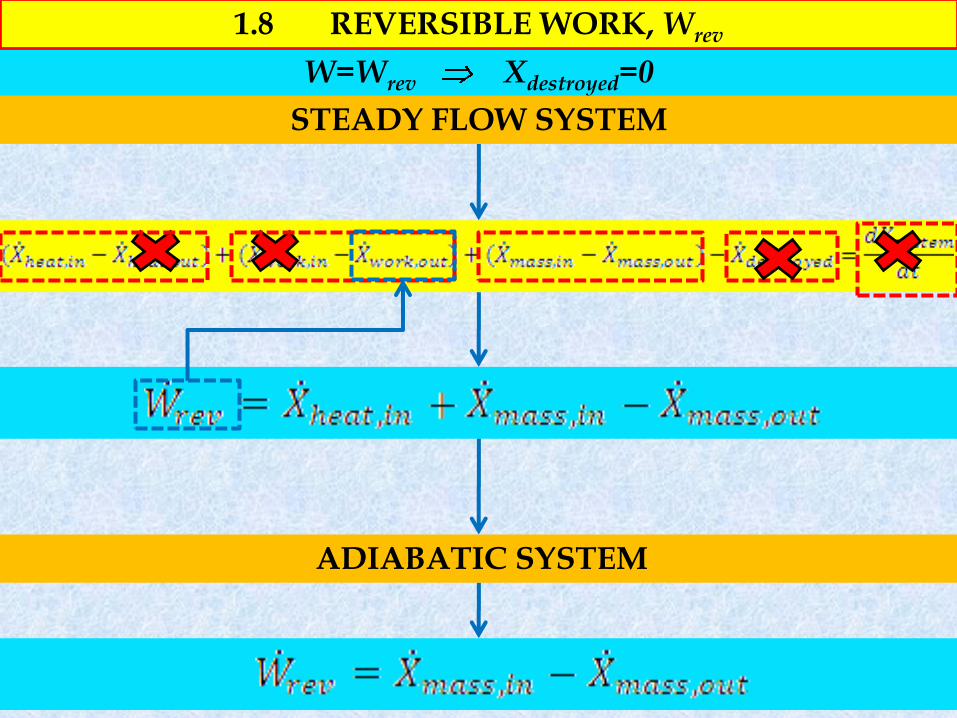
ADIABATIC SYSTEM
W=Wrev Xdestroyed=0
STEADY FLOW SYSTEM
1.8 REVERSIBLE WORK, Wrev
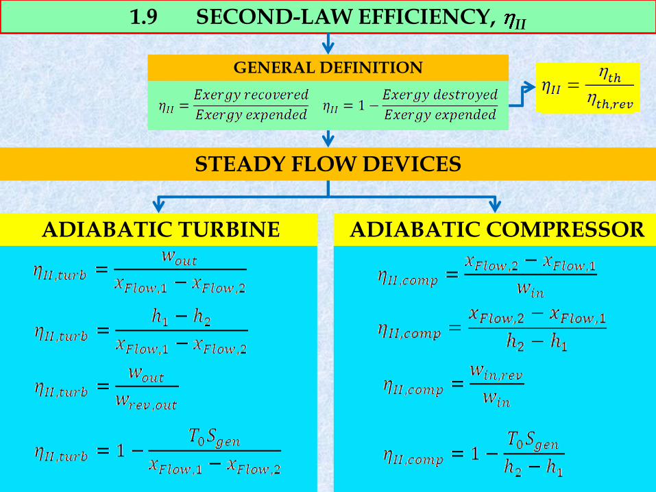
1.9 SECOND-LAW EFFICIENCY, II
GENERAL DEFINITION
STEADY FLOW DEVICES
ADIABATIC TURBINE ADIABATIC COMPRESSOR
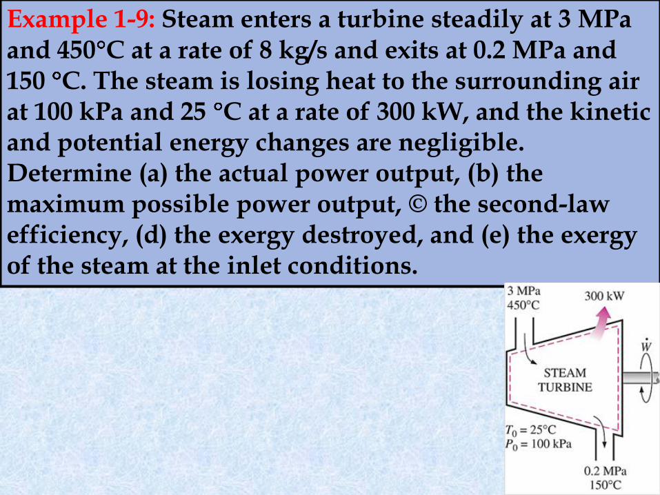
Example 1-9: Steam enters a turbine steadily at 3 MPa and 450 C at a rate of 8 kg/s and exits at 0.2 MPa and 150 C. The steam is losing heat to the surrounding air at 100 kPa and 25 C at a rate of 300 kW, and the kinetic and potential energy changes are negligible. Determine (a) the actual power output, (b) the maximum possible power output, © the second-law efficiency, (d) the exergy destroyed, and (e) the exergy of the steam at the inlet conditions.

END OF CHAPTER 1
EXERGY: A MEASURE OF WORK POTENTIAL


