Page 1
®
Chapter 1 Installation Foundations
Chapter 1 establishes the fundamentals of information technology systems (ITS) installation practices and recommends strategies for enhancing professionalism in the ITS workplace. This chapter provides ITS installers with information related to industry terminology, ����������������� �������������������������communications/customer relations best practices.
Page 3
Chapter 1: Installation Foundations
© 2010 BICSI® 1-i ITS Installation Methods Manual, 6th edition
Table of Contents
SECTION 1: TRANSMISSION
Transmission Methods and Media . . . . . . . . . . . . . . . . . . . . . . . . . . . . . . 1-1
Introduction . . . . . . . . . . . . . . . . . . . . . . . . . . . . . . . . . . . . . . . . . . . . . . . . . . 1-1
Terminology . . . . . . . . . . . . . . . . . . . . . . . . . . . . . . . . . . . . . . . . . . . . . . . . . . 1-2
Power, Current, and Voltage . . . . . . . . . . . . . . . . . . . . . . . . . . . . . . . . . . . . 1-2
Alternating Current (ac) and Direct Current (dc) . . . . . . . . . . . . . . . . . . . . . . 1-3
Electromagnetics . . . . . . . . . . . . . . . . . . . . . . . . . . . . . . . . . . . . . . . . . . . . 1-4
Frequency . . . . . . . . . . . . . . . . . . . . . . . . . . . . . . . . . . . . . . . . . . . . . . . . . 1-6
Bandwidth . . . . . . . . . . . . . . . . . . . . . . . . . . . . . . . . . . . . . . . . . . . . . . . . . 1-6
Signal . . . . . . . . . . . . . . . . . . . . . . . . . . . . . . . . . . . . . . . . . . . . . . . . . . . . 1-6
Digital Transmissions . . . . . . . . . . . . . . . . . . . . . . . . . . . . . . . . . . . . . . . . . 1-7
Analog to Digital Conversion . . . . . . . . . . . . . . . . . . . . . . . . . . . . . . . . . . . . 1-8
Analog and Digital Subscriber Line (DSL) Convergence . . . . . . . . . . . . . . . . . . 1-9
Megahertz (MHz) and Megabit (Mb) . . . . . . . . . . . . . . . . . . . . . . . . . . . . . . 1-10
Decibel (dB) . . . . . . . . . . . . . . . . . . . . . . . . . . . . . . . . . . . . . . . . . . . . . . 1-10
Copper Cabling Media . . . . . . . . . . . . . . . . . . . . . . . . . . . . . . . . . . . . . . 1-11
Overview . . . . . . . . . . . . . . . . . . . . . . . . . . . . . . . . . . . . . . . . . . . . . . . . . . . 1-11
American Wire Gauge (AWG) . . . . . . . . . . . . . . . . . . . . . . . . . . . . . . . . . . . . . 1-11
Basis of the American Wire Gauge (AWG) Numbering System . . . . . . . . . . . . 1-11
Solid Conductor Diameters . . . . . . . . . . . . . . . . . . . . . . . . . . . . . . . . . . . . 1-11
Resistance . . . . . . . . . . . . . . . . . . . . . . . . . . . . . . . . . . . . . . . . . . . . . . . . . . 1-12
Inductance . . . . . . . . . . . . . . . . . . . . . . . . . . . . . . . . . . . . . . . . . . . . . . . . . . 1-13
Capacitance . . . . . . . . . . . . . . . . . . . . . . . . . . . . . . . . . . . . . . . . . . . . . . . . . 1-14
Impedance . . . . . . . . . . . . . . . . . . . . . . . . . . . . . . . . . . . . . . . . . . . . . . . . . . 1-14
Characteristic Impedance . . . . . . . . . . . . . . . . . . . . . . . . . . . . . . . . . . . . . . . . 1-14
Insertion Loss (Attenuation) . . . . . . . . . . . . . . . . . . . . . . . . . . . . . . . . . . . . . . 1-15
Return Loss . . . . . . . . . . . . . . . . . . . . . . . . . . . . . . . . . . . . . . . . . . . . . . . . . 1-15
Crosstalk . . . . . . . . . . . . . . . . . . . . . . . . . . . . . . . . . . . . . . . . . . . . . . . . . . . 1-16
Near-End Crosstalk (NEXT) . . . . . . . . . . . . . . . . . . . . . . . . . . . . . . . . . . . . 1-16
Far-End Crosstalk (FEXT) . . . . . . . . . . . . . . . . . . . . . . . . . . . . . . . . . . . . . 1-16
Alien Crosstalk (AXT) . . . . . . . . . . . . . . . . . . . . . . . . . . . . . . . . . . . . . . . . 1-18
Installation Considerations Related to Alien Crosstalk (AXT) and Bundling of Cabling . . . . . . . . . . . . . . . . . . . . . . . . . . . . . . . . . . . . . . . . . . . . . . . . 1-19
Mixing Category 6A/class EA and Higher Cabling with Lower Performing Cabling . . . . . . . . . . . . . . . . . . . . . . . . . . . . . . . . . . . . . . . . . . . . . . . . . . 1-20
Page 4
Chapter 1: Installation Foundations
ITS Installation Methods Manual, 6th edition 1-ii © 2010 BICSI®
Nominal Velocity of Propagation (NVP). . . . . . . . . . . . . . . . . . . . . . . . . . . . . . . 1-21
Propagation Delay . . . . . . . . . . . . . . . . . . . . . . . . . . . . . . . . . . . . . . . . . . . . . 1-21
Delay Skew . . . . . . . . . . . . . . . . . . . . . . . . . . . . . . . . . . . . . . . . . . . . . . . . . 1-21
Insulation. . . . . . . . . . . . . . . . . . . . . . . . . . . . . . . . . . . . . . . . . . . . . . . . . . . 1-21
Pair Twist . . . . . . . . . . . . . . . . . . . . . . . . . . . . . . . . . . . . . . . . . . . . . . . . . . . 1-22
Shielding . . . . . . . . . . . . . . . . . . . . . . . . . . . . . . . . . . . . . . . . . . . . . . . . . . . 1-23
Coaxial Cables . . . . . . . . . . . . . . . . . . . . . . . . . . . . . . . . . . . . . . . . . . . . . . . 1-26
Hardware . . . . . . . . . . . . . . . . . . . . . . . . . . . . . . . . . . . . . . . . . . . . . . . . . . . 1-26
Optical Fiber Cabling Media . . . . . . . . . . . . . . . . . . . . . . . . . . . . . . . . . 1-27
Overview . . . . . . . . . . . . . . . . . . . . . . . . . . . . . . . . . . . . . . . . . . . . . . . . . . . 1-27
Bandwidth . . . . . . . . . . . . . . . . . . . . . . . . . . . . . . . . . . . . . . . . . . . . . . . . . . 1-29
Dispersion . . . . . . . . . . . . . . . . . . . . . . . . . . . . . . . . . . . . . . . . . . . . . . . . . . 1-29
Modal Dispersion . . . . . . . . . . . . . . . . . . . . . . . . . . . . . . . . . . . . . . . . . . . 1-29
Chromatic Dispersion . . . . . . . . . . . . . . . . . . . . . . . . . . . . . . . . . . . . . . . . 1-30
Differential Mode Delay (DMD) . . . . . . . . . . . . . . . . . . . . . . . . . . . . . . . . . . . . 1-31
Attenuation . . . . . . . . . . . . . . . . . . . . . . . . . . . . . . . . . . . . . . . . . . . . . . . . . 1-32
SECTION 2: PROFESSIONALISM
Professionalism . . . . . . . . . . . . . . . . . . . . . . . . . . . . . . . . . . . . . . . . . . 1-33
Overview . . . . . . . . . . . . . . . . . . . . . . . . . . . . . . . . . . . . . . . . . . . . . . . . . . . 1-33
Technical Expertise . . . . . . . . . . . . . . . . . . . . . . . . . . . . . . . . . . . . . . . . . . . . 1-33
Project Objectives . . . . . . . . . . . . . . . . . . . . . . . . . . . . . . . . . . . . . . . . . . . . . 1-33
Project Team Members . . . . . . . . . . . . . . . . . . . . . . . . . . . . . . . . . . . . . . . . . 1-34
Team Member Responsibilities . . . . . . . . . . . . . . . . . . . . . . . . . . . . . . . . . . 1-34
Interpersonal Skills and Communication Requirements . . . . . . . . . . . . . . . . . . . 1-35
Effective Communication Skills . . . . . . . . . . . . . . . . . . . . . . . . . . . . . . . . . 1-35
Customer Relations . . . . . . . . . . . . . . . . . . . . . . . . . . . . . . . . . . . . . . . . . 1-37
Customer Perception . . . . . . . . . . . . . . . . . . . . . . . . . . . . . . . . . . . . . . . . 1-37
Feedback and Follow-Through . . . . . . . . . . . . . . . . . . . . . . . . . . . . . . . . . . 1-38
Professional Appearance . . . . . . . . . . . . . . . . . . . . . . . . . . . . . . . . . . . . . . 1-38
Appendix: Conductor Size . . . . . . . . . . . . . . . . . . . . . . . . . . . . . . . . . . . 1-39
References . . . . . . . . . . . . . . . . . . . . . . . . . . . . . . . . . . . . . . . . . . . . . . 1-41
Page 5
Chapter 1: Installation Foundations
© 2010 BICSI® 1-iii ITS Installation Methods Manual, 6th edition
Figures
Figure 1.1 Analog sine wave . . . . . . . . . . . . . . . . . . . . . . . . . . . . . . . . . . . . . . . 1-4
Figure 1.2 Digital signal . . . . . . . . . . . . . . . . . . . . . . . . . . . . . . . . . . . . . . . . . . 1-7
Figure 1.3 Ohm’s law . . . . . . . . . . . . . . . . . . . . . . . . . . . . . . . . . . . . . . . . . . . 1-13
Figure 1.4 Schematic of a transmission line . . . . . . . . . . . . . . . . . . . . . . . . . . . . 1-14
Figure 1.5 Crosstalk paths . . . . . . . . . . . . . . . . . . . . . . . . . . . . . . . . . . . . . . . . 1-17
��������� �� ����������������������������������������������������� . . . . . . . . 1-18
Figure 1.7 Typical balanced twisted-pair cable . . . . . . . . . . . . . . . . . . . . . . . . . . 1-22
Figure 1.8 Examples of foil-screened and braid-screened cables . . . . . . . . . . . . . 1-24
Figure 1.9 Examples of screened and unscreened balanced twisted-pair cables . . . 1-25
Figure 1.10 Modal dispersion . . . . . . . . . . . . . . . . . . . . . . . . . . . . . . . . . . . . . . . 1-29
Figure 1.11 Chromatic dispersion . . . . . . . . . . . . . . . . . . . . . . . . . . . . . . . . . . . . 1-30
��������� ���������������������������������������. . . . . . . . . . . . . . . . . . . . . . . 1-31
Figure 1.13 Communications perceptions . . . . . . . . . . . . . . . . . . . . . . . . . . . . . . 1-38
Tables
Table 1.1 Cable bundling restrictions when cables are produced by different manufacturers . . . . . . . . . . . . . . . . . . . . . . . . . . . . . . . . . . . . . . . . 1-19
Table 1.2 Mixing category 6A/class EA and higher cabling with lower performing cabling . . . . . . . . . . . . . . . . . . . . . . . . . . . . . . . . . . . . . . . . . . . . . . 1-20
������!� "����������������������#���$����%������������������ . . . . . . . . . . . . 1-28
������&� "���������������������������������%������������������ . . . . . . . . . . . 1-28
Table 1.5 Project communications . . . . . . . . . . . . . . . . . . . . . . . . . . . . . . . . . . 1-36
Table 1.6 Conductor size . . . . . . . . . . . . . . . . . . . . . . . . . . . . . . . . . . . . . . . . 1-39
Page 6
Section 1: Transmission Chapter 1: Installation Foundations
© 2010 BICSI® 1-1 ITS Installation Methods Manual, 6th edition
Transmission Methods and Media
Introduction
This section discusses the transmission of information over various physical media. It also ���� ����� �������� � �� �������� ���� ������������ ������������������� �� ������ �����have on the transmission of information.
In the context of this manual, transmission is the movement of information in the form of ��� ���������� ������������������������ � ����� ���� ��������� ������� ��������������������������� ��� ������������ ��������� ���������������� ����������� �� ����������������� ������ �������������� ���������� ��� �������������������������������������� �������
Three transmission methods are:!� �����"�������� ������ ��������������������� ���������#����������������� ���������� �� �"�������������"� ��������������������������� �������$��%��&����������������� ������������ ����������$����������� �������������� �� ����������!� '�������"������������ ������ ������������� ��������� ����� ����������������� ����� ����� ���������� ������� ������������ ���������*�������������� �� ������ � �����������&�&����� ��+����� �� �$-���� ������������� ����&����������� ������������������� ��������� �� circuits.!� 0������"������������ ������ ������������ ������� ������ � �������� �����#� ���������� ������ �������������"���������� ����� ���� �� �$����� ��������
������������������������ ������� �������������2����������������������� �������� considerations such as the:!� 3������������ ������ �������!� �����������&����� �������&������������&�������� ���&������!� ��������������4����� ����� ���$�!� ��������������� ����� �����!� ������������������������������� ���� ������� ���������
���������� ��� ����������������� ���������� �����&���������� �������� ������� ��� �� �����������56�������� ���������� ����������������������������� ��� ������������������������������ ����������������� ����� ����� ���������� ��� ������������������ ������������������� ���56����� ������������������������������� ��� ����������������
Page 7
ITS Installation Methods Manual, 6th edition 1-2 © 2010 BICSI®
Chapter 1: Installation Foundations Section 1: Transmission
Introduction, continued
#�������� ��� �������������� ����������������� ������� ���� ������������������ ���� ���� �� ���� ���������� ����������� �&�������������������� �����6��������� ����� ���������������������������������� ���$���*������� �������������� ���$���*������� ������$������
0���������� ��� ��������������� ������������ �������� ����������������� ������������������ ������������� ������78�����9���� ������;�8�����<���� ������=8�����5���� ������=#8�����5#, �� ������>8�����0���� ������>#8�����0#�����&������������������� ������ ���������� ������� ������������� ������*������ � �� ������ ������ ���������� ���
���� �������������������������������������� ��������������� ��� �������� �� ������ �������� � ���������� �� ����9��"�������������������������� ��� ��������� ����are at different potential.
Terminology
�������� ����������� �����?��� ������������ ����� �������� ������������������?�� �&����� ������� �������� � �� ������������������� �� ����������&����������� ������������ characteristics.
Power, Current, and Voltage
������������������3���������������� ���@������ ���&���� ���������$��������������� �������� �&���������@��������������� ���� ��������� ������������������������� ���� �������������������� �� ��������������������������� �������&�������������� ������������� �������� ������ �����3������������&����������� ��������������������������&� ���A��������� ����������� ����������������������#���B��������� �����������&� ���������� ����� ������� ����� ����������������������� ��������� �� ���*��� � ������� ������&������#�������������� ��&����&� ������ ��� ������� �2�������� ����&������������������� ��������������� � ������4������&���� ���������� ��������������� ����
#������ �����������*��� �� ���&� �����A���� �������� ��������� ��������3�D�A���� ���� ��������������������&� ����������A#���#������ ����������������������� ���� ���������� ������������ �� �� ���&������ �&���������� �������� �������������� �����
3��$��������33����3���������������� ��@��� ������ ����A�E������� �������������#��� 6������ ������������ ��������&����������������A#� ����������������� ��������F��� �&���������������� �� ���������� ������� ������� �&������������� �������������� ������������������������&� ������������� �&���A#F���F��� �&��������������� ����������� ����������� ��������������������� ���������������������������
Page 8
Section 1: Transmission Chapter 1: Installation Foundations
© 2010 BICSI® 1-3 ITS Installation Methods Manual, 6th edition
Terminology, continued
3��$�������������������������� ��������&����������� ���� �� �����&�����&���������������� ������� ��� ������� ��� �����"����������� �� ������*���������� �����&���� ������� �������������������� ������'���&�������$���������������� ����� ��������������������#�� ��������� �������������������� ��������&�������������3#���#&��������������� ������ �������������&��� >G������� ���� �������������������������� �H�� ��������� �� ����������� ���������������� 3#� D� G�>G>�E�A�E�#5J#63K5L� #���&��������� ����� ���"�������������������������� ����������M�;�#�� �NOG�A�
3� D� M�;�#�E�NOG�A� D� ;MG�A# � 3#� D� G�>G>�E�M�;�E�NOG� D� 7PO�@
��������� ���������� �2�������� ����������� ����������� ����������&������������������� �� �� ������������������� ���������������
5�� �������*������ ��������� ����� ����������������B3����������������� ������ ����������������������@��������������� �������������������A#�
Alternating Current (ac) and Direct Current (dc)
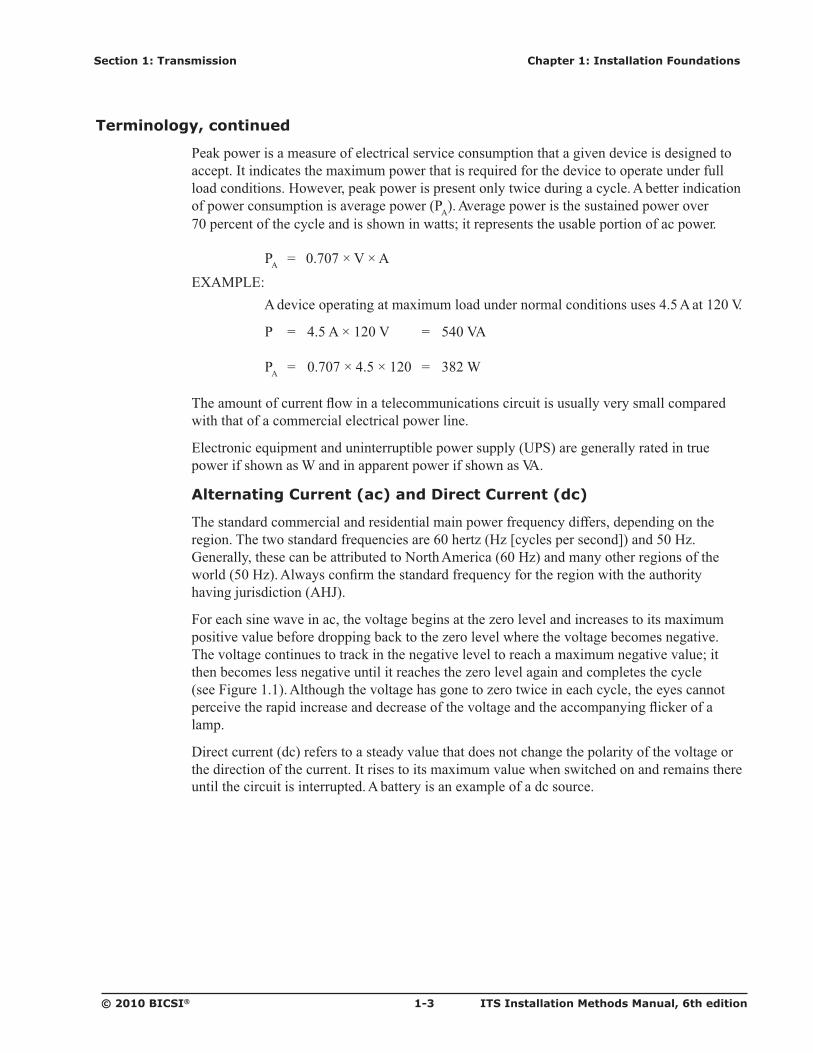
����� ���������������������������� �����������������*���������������������������� ��������������� ���� ����������*������������=G���� 4��'4�Q����������������R������;G�'4�� U�������� ������������ ��� ��� ��V�� ��#��������=G�'4������������ ��������������� ���������;G�'4���#������������ ���� ����������*���������� ������������ �� ����� ���� �� ��&����?������� �����#'W��
0���������������&��������� ���&� ����������� � ���4�����&���������������� ��� ����"����� ���� �&��&���������������������$� �� ���4�����&�������� ���&� ��������������� �&�������&� ������� ������ �� ���$���� ������� �&���&�� ������������"��������� �&��&���H�� � ������������������� �&���� ��� ��������� ���4�����&����������������� ��� �������� �����0������N�N���# ������ ���&� ������������� ��4���� ������������������� ������������� � ������&�� ���������������������������������� ���&� �������� ����������������2��$��������lamp.
<���� ������� ������������� ����� �����&���� �� �������� �������� �������� ����� ���&� ������� �������� ������� ��������� ��� ������� ��� ����"�����&������������ �������������������� ������� �� ��������� ������ ����� ����#�� �����������"��������������������
Page 9
ITS Installation Methods Manual, 6th edition 1-4 © 2010 BICSI®
Chapter 1: Installation Foundations Section 1: Transmission
Terminology, continued
Figure 1.1 Analog sine wave
Electromagnetics
#���� ������� �&� �������������� ������������� ���������B���� �������������� ����������������������4����� ������������������ ����������� ����� �������������� ������������������������ ������ �� ������ ��������������� ���������� ����������� ���������� ��������������� � ��������� �&���$�������� ����������� ��������������� �� ������������ ��� �����
������?�� �����56���������������*�������� �����������F0�������&���������"��'���&���������� ���������&�&���� ����������� ����������������� ������������ ��� ����� �����&���������� ��������������������4����� ����������� ����������� ����������� ����� ��������������� �� ������������������������������������ �������������������������� ������ ��������������� �������������������������� �������� �������������������
A��������&������56�8F0����������������������������������������� ������������� � ������ ������*������ ��������������� ������������?���� ������������������������������ ������������" ������"��������#�������� ��� ������ �� �����������&������������ ����������V����������������������� ������������������ ������������ �� ������ ��56�����F0���������L!� 56����� ���������������� ���������� �� ������������� ���������� ������������ from an � �" ��������������������� �� ����������������" ����� �� ��������������� ���������Q������� ����� �$��#J��R���� �����2�������� ���� �������� �������������������������� ����� �� �� � ������������������� ����������� ���� ������� ��Q����� �$R��������� ������%���������� �� ������������ ������ ������������ � �� ����������������������������������!� F0���������� ���������� �������� ������������������ ������� ������� ���������������������� ���2�� ��� �������������������
Amplitude
+
0
Directionchange point
1 Cycle
Time
_
Page 10
Section 1: Transmission Chapter 1: Installation Foundations
© 2010 BICSI® 1-5 ITS Installation Methods Manual, 6th edition
Terminology, continued
#����������� ������������ ��� ����;GG������������U���������� ����������� �� ���������&������������ ��������A<������������ �� ����� ��� ������������� �������������������� ����������������������6F������������������������������&� ��������������� �������A<������������ ����������������������������� ������������������ ����� �� ����
��������� �� ���������A<��������������������������� ������� ���������560��������� ���;��U��6�� ������������� �� �������A<������ ������� ������&� �������� ������������� ;G�'4����=G�'4���������� ��� �����*������ ���������&������������������� ���������������� ����������������������������������������������� ���560������������������ ������������*������ ����?���� ����� ���������������������� �� ��������������������"��� �� �� ���&�� ���A<��
� ��������� �� � ����� ��������� �����560����������������� ������� ��������������������� ��������������� ����������������������������������� �������������������������� ������� ���# ������ �������������������������� ������� ��������������� �������� ���������������� �������������� ������� ��������������� ����&������� ��� ����� �� ����������*�� ���������� ��V� ������� ���������$�������� ���� ����� �������������� �������������������$����� �� ���������� ������ ������&������� ���������������������� �&�������� ������� �� ��������� �&�������� ������������X������� ������������� ������������ ����������� ������ ���� ������������� �� �$������������ ���� ������������ ��������������� ���� �������� � ����*������ �������5F�������������� ������� ����������� ������������������ ����������� ��������������������� �������������������� ��
5�� ����������&��� ����������������� ���������� � �� ��&������������������� ������ ������ ���� �������� � ���������������� ������ ����������� ������������F�����5F��������������� �������������� �������*������ ������� �������� ����� �� ����������� ����������������������������� ��������� �� � ��������4�� ��������������� ����������� ����� ��� ��� �����*������ �������� ���������� ��� ����������� �������� ����������
��� ���5F��56������������� ������ �� ����������� ����������� ������������ ��� �����$� ������� ������ ������ �� ������������������������������ ������� ����� �� �� ��������� ������ �������� ��������� ��������� ��� ����������������� ������� ����������� ������������� ������������� ���������������� ����� ���� ����������� ������ ������� ������������������ �&������������ ��� �������������� ���
������� ������ ����������������������������� ���������������������56����������������������� ����������*������ ������������$����������� �� �� ���������������� �� ������������ ������*������ ������������*������ �
Page 11
ITS Installation Methods Manual, 6th edition 1-6 © 2010 BICSI®
Chapter 1: Installation Foundations Section 1: Transmission
Terminology, continued
Frequency
0��*������������������� ���������������������������������� ����������&��� �������������������������������������������������������&�������0������N�N������ ������ ���� ��������*��� ��N������������� ������*���������� � ������N�'4�
�������������������*��������� ���4������������L!� N���������N���D�N�'4!� =G����������N���D�=G�'4!� NGGG����������N���D�N�$����� 4��$'4�!� N��������N�GGG�GGG�����������N���D�N�������� 4��6'4�!� N�������N�GGG�GGG�GGG�����������N���D�N�������� 4��U'4�!� N� �������N�GGG�GGG�GGG�GGG�����������N���D�N� ������ 4���'4�
# �������������������������*�������� �� ������������OG�'4� ��OG�GGG�'4�� ������&�������������� ����� ������������������� ����������������������� ��� ��NGG� ��MGGG�'4�� ������������������������������������� ��� ��7GG�'4� ��7MGG�'4����������&���� �����?��� ����� ������$���&��������������������������&���� ���������� �����
Bandwidth
Y������ ����� ���������� ������������������� ���������� ���������&���������� �������� ����������� �������� ��������� ��� �� ��������� �&�������� ������� ���������� ���� ������������� ����������� ���������� ����������&������������������ ����� ��
Signal
����������� ���� ������ ������� ����������� �������� �������������� ����� ��� �������� �������Z�������������� ���#������� ������������������&������������������ ����� ������ �������&���� ������� ������������������������ ���� ������������� �������� ��������� �L!� #����������Z#������������&�������� ��� ��������������������������+������� ��-��� #����� �������������������� ��������&���������� ������������ �� ������ ���������������� ������� �� ��������������������������� ������������*������� �������� ������� ���������� �������������&�������0������ ������ ��� ������ �������� �����������&�� ����������&��� ���� ������������ ����������� �� �&������������� ������������ ���� �������� ���� �� ��� � ����������� ���&���������&������������*����������� ���� �� ��� ������� ���&�����
Page 12
Section 1: Transmission Chapter 1: Installation Foundations
© 2010 BICSI® 1-7 ITS Installation Methods Manual, 6th edition
Terminology, continued
!� <��� �������Z#����� ������������������� ������������� �� ������������������� � �� ���� ��� ��������������������� ��� �� ������ �����"���� ��������� ������ �������0������N�O�������� � ������������� ��������� ���� � �������������&��Z����������������� ���+��-� ����� ��� � � ���������&���������������� �� ������� ������N�������+���-� ����� ��� ����4�����&��� �� �������������� �� ������� �4�����G���X ��������������������� ���������� � ��� ���� � ��� � ����������� �&���������� �&��&� �����
Figure 1.2 Digital signal
V = volt
�������� ���������������� ���������*��������� ��������� ���������� ��� ������ ���� ������������������� ������ ��&����������� ��������������� �������������������������������� ��� ������ ���������� �������������������������� � ����������� ����$�������� ������������������������������������������� ����� �����*�������������� ����
Digital Transmissions
������������ �������� ��������� ���������� ������� ��� ������� ��� �������������� ���� ��������� �������� �� ����"�� �������� ������������ � ����������� ������������������������������ ��������� ����������� �2���������� ����� �������� ���������������� � ���
������������� ��������� ������ ��������������� ��� �����������&� �����&�����8����� � ����������"�� ���������� �2��� ���� ���� ����������������� �2�������� �����������������������������8����� � ������������������� �������� �����&� ����������� ���������������� ������ ��������������� ��� ��������� �������������������������&���&� ����������� ������������� ������������ ������������
VX�5L� ���������&� ��������� ������������������������4��������������&� ��������� �� ������� ���� �� ������ ��������� ������������� �2��������$���������&����� ����� &� �����&���OM�A�����MP�A�������������
Voltage
0 00 1 0 011 1 11
0 V
+3 V
-3 V
Page 13
ITS Installation Methods Manual, 6th edition 1-8 © 2010 BICSI®
Chapter 1: Installation Foundations Section 1: Transmission
Terminology, continued
5J#63K5L
� @��������&������� �� �� ���� �������������� �����������������������&� ������� ���������&���������OM�A����#���������[�7�A������������ ��������� � ������� ������ ����&� �������������������OM�A� ��O>�A��@���� ���&� �����&���� ����� �� ��� � OM�A������� �������������� ��������� � ��
� ������"������"���������������� �&��&� �����������������$��������� � ����� ���� ��4����QVF\R����������� ���������������[�7�A�����]�7�A��� ����]�7�A � ����������� �� �����������������&� ���������OM�A� ��ON�A������������� ���� �� ���� �&�������������� � ������ ����������������� � ��������� ����[�7�A��O>�A����� � ]�7�A��ON�A��������������� � ���������OM�A�
� @����������������� ���������������� ������������*�������������M����P�� ���� ������ ��$�������������������$�� �� ��������&���������� ���������������� ���� �� ��� ������&�������������������������������������������� ��������������$�� ������ ������������� ����
Modem
���� ������������������� ���� ��������������� �������������������������������� ����� ��������&��������� �������� ������ ����������&�� ��� ������������������� ��������� ��8 ������� ����������������������������&�� � ������� �������%��N������G���� �� ������ ��� ����������*���������������������� ������N������G���������������������� ���� ������ ����&������ ������� �������������� �������������������&������� � ��������� ������ �������� �� ��������������� ��������
Codec
���� ����������������������� ��������&�������&���������������&�� ������������������� � ������ ���� ���������8���������������������������������&�� � ������� ���������������&����������*���������� �������� ������� ����� �������������&������� �� ������������������������������������&������� � ��������� ������ �������� �� ���&������������
Analog to Digital Conversion
0������������� ���������&������� ������&������� �������� ������������ �������������&����� ���� ����������&�&����������������������#�������������������������� ���������� �� ������������� ���� ���������������� ��������������� ����������������%���� ��
������� ��������������������&��������&������������������������������ �����396���396�������� ���������&�����������PGGG� ���������������� ������ �������� ��&���������������=M�GGG�� ��������������#�������������� ������ �����'���&����� ������ ����� ����������� ���&������� ���������� ��� �����������������������������������&������&����� ���� � ��� �����A��3������������������������ �������������� ���@��0���
Page 14
Section 1: Transmission Chapter 1: Installation Foundations
© 2010 BICSI® 1-9 ITS Installation Methods Manual, 6th edition
Terminology, continued
Analog and Digital Subscriber Line (DSL) Convergence
������������ ���������������&�&�������� ����������� ������������ ���� ���������������&�&������������������� ��������������<�� ��� �������� �����&�&�������������� ��������������� ��������������������� ���� ����� ������������&����������� ���� ����� ��������������� ��� �������� �������������������������� ������������������ ������ ��&��������� ���� ��������������� ������������5 ����� ���
��������������� ����������� ����� ���������� ���$��3��V��������� ������������� ���������������� �����������&�����3X����&�������������� ����������������������3X��� ��������������� ������ ���� �����7GG�����7MGG�'4����������������������� �������������������������� �����������������9�������$��������&�������������� ���� �������������� ���������� ������� ������ ��������������������� ��� ������������������������������� ���� ��� ���������"������� ����� ��������������� ��������� �������������� ���*����������������� ���7�M�$'4���������� �����3X���
<��� ����������������<�K�� ���������������&����������� ����&�� ���3X��������� ������ ����M7NO�;�'4��������������� �����NG�����NGG�$'4������������������� ������ �����������������#��� ������������������ ������� ����������������������*������������ �� N�N�6'4����������� �������� ���������������Q#<�KR���� ���������������������������������6������������������*�� ��� ��������&����������� ������������������������������ ������� ��� �� ����������� ����*������������������ �������������� ����� ������������������� ��� ������ ��&�� ��������� �������������������� �����<�K� �������&�������� �� ������ ��� ���*��� �����������������������������������&�� ������������&�������������������� ���� �������������
����� ������������������������ ������������ ���7GG]7MGG�'4���������<�K������������� �����*�������������MGGG�'4� �������������M�6'4����������*���������������� ����������<�K����&��������3X��� �����"�� ���� ��������������� ��� ��������
#<�K����������������<�K� ������������������������ ����� �� �������������&���������� ��� ���������������� �������#<�K�����������"�������������O=�GGG�$'4� ��N7>�PO;�$'4�������� �������������� ��������N7P�$'4� ��NNGM�$'4���������� �������������� ��������������*���������������������� �������������� ����������5������������������� ����� ������"��������N;�� ������������ �����<��������� ������������4� ����� ���������� ���#<�K� ������ �� ���������� ������� ���� ����� ��������� ���������� �����VF��� ��������� ���*����������� � ����"����������� ������&���������������� ���� ������������������ �����<�K������������������� ����� ������ ���������� ���Y� ������� ������������ ������VF��� ������������ �� ������&��������� ���*��� �������<�K������� ��
������������������� ���� �������� �� ��������������������������*�������������������&�������� �������� ���������� ������ ������� ����������
Page 15
ITS Installation Methods Manual, 6th edition 1-10 © 2010 BICSI®
Chapter 1: Installation Foundations Section 1: Transmission
Terminology, continued
Megahertz (MHz) and Megabit (Mb)
� ��������� �� � �������� ���� ������ ��������� ������������ 4���������� ���6������ 4�*��� ����� ��������� ���������������� �����������*����������������� ���� �������� N]NGGG�6'4��� ������>#8�����0#����������������� ��� �� ���������� ������������������ ����� ������������������4����� ������������
6���� ��6��������� �� ������������� ������������ ���� �� ������� ������� ����&��� ��� �������������&���������� ��������������������������� �� �� ������� ������� ����&��� �������������� ���������� ��� ������������������������������������ ����@� ���������� ������������������������������������� ������� ������� �����������������������&��������6���������"�����������������������������������������&���� ����� ������������ ���� ������� ���������������������� ����&���������������� ������� ����
Decibel (dB)
#������������������������� ���� ��������������� ���������������� ������������ ����������������#�"������U������Y���#����������������� �������������������$���������������Y���������� �� �������������������� ������ �������� ��&����� ����� ������ ���������������� ��������������������������������������� �����&� ����
��� ������������� ���� �������� �������� � �������������������������������0����"����������������������"��� �����������������NG��Y���������� ���������������������������� ��������"��� ����������G�7��Y��<�������"���������� ������ ���&������� � ����� �������� �������
�������������������� ����������������� ������������� ���� �� �����������&���� ����� �������������&���������������� �����������������������������7��Y�������� ������������������&������� ������������������������������������=��Y������������������������&������� ���&� ����
��������������������������NG��Y���������������OG��Y�����&� ������������� �������������������������������������NG� ����� �����������&������������&��� �������������� �����������������������$������0����"��������� ������� �����������*��� ��N�@����������������NG��Y������&����&�������G�N�@H�����&�������������������NG��Y������&������� �� ����NG�@�
�������������������� �����Y���L �Y� D� NG�����3N8�3O�
@�����3N ��� �����&������ �� �����������3O ��� ������� �������
#������"������������������ ��������� ���� �� �������������������������� ���� performance include:!� 9���� �$Z����������� ���������&����� ���� ���!� ����� ������������������� ���� ����Z��������� ���������&����� ���� ���!� F� �������Z����������� ���������&����� ���� ���
Page 16
Section 1: Transmission Chapter 1: Installation Foundations
© 2010 BICSI® 1-11 ITS Installation Methods Manual, 6th edition
Copper Cabling Media
Overview
@� ������������������������������������� ��&�������������� ���������� ������� ���medium from the transmitter to the receiver to drive the receiver.
������� ������ �&������������� � ����������������������������� ��� ������������������ �������� ������������������ �������� ������������������������ ���� �������������
�������� ������������� ������ ����������� ���� �� ���$����������� ���� ��������������������������� ���� ������������������������ ������������������������������������ �� ����methods or procedures.
American Wire Gauge (AWG)
����������������������� ����� �������4� ����� ���#��������������������#@U����4������� �������������������������� ������������
����#@U���� ����������� �� ��������� ����&�������� �������������������������������&�������physical dimensions of conductor materials.
Basis of the American Wire Gauge (AWG) Numbering System
'�� �������� �����4������ ���#@U���� ������������������ � ������������� ���� �� ������ ��&�&������ ��������������������������������������� ���#@U������������ �����4����� ��������� ������������ ���&�������&�������� ��������
��� ���#@U���� ��L!� ����������������� ���������������������� ������������������������ ������&�&����!� K����������������� ���������������������� ����������������������� ������&�&����
Solid Conductor Diameters
���������� �������� �������� ���#@U���� ������������������"�� diameters for the ����� ���4���7=�#@U�D�;��������� �������� ���4���M8G�D�M=G������������N��������*��� ��G�GO;M������ ��������QG�GGN������������R������������ �������� ����� ������� ����4�����������&�������� �������� ���4����� �������� ���4������������ ��������� ����������������
����#@U�������������� ������������������������������������������ �������� ������������������������������� ����������������� ���L!� #�����������������7������"��� ��������������&��� ��������� ��%����������� ����������!� #�����������������7������"��� ��������������&��� ��������� ��%������� �����!� #�����������������=������"��� ��������������&��� ��������� ��%������� ���
Page 17
ITS Installation Methods Manual, 6th edition 1-12 © 2010 BICSI®
Chapter 1: Installation Foundations Section 1: Transmission
Resistance
0����� ���������� ������ ��������������� ������������� ������� ������ ����&���������������� �����9��������������������������� ����������������� ����� �� ���2�� of electrical ����������������� �&����������������������������� ��� ������ ���
F���� �������� ��������� ������������� ��� ������� � ���2��������� ���� �� �������� ��F���� ���������"�����������������X��������������� �������������������������������� � ��2�� ���������&� ������� ���������������������������������� � ����� ���� ��������X��%����������0������N�7����L
� A� D� ��E�F
or
� F� D� A�8��
or
� �� D� A�8�F
@�����A����&� �������&� �������������� �����������������F��������� ��������������
Page 18
Section 1: Transmission Chapter 1: Installation Foundations
© 2010 BICSI® 1-13 ITS Installation Methods Manual, 6th edition
Resistance, continued
Figure 1.3 Ohm’s law
V = Voltage in volts I = Current in amperes R = Resistance in ohms
X��%�����&�����������������&����3����������������&��� ���������0������N�7������������������ �� �A������&�������F��3����������������&��� ���F����������������� �� �A������&����������3����������������&��� ���A����������������� �� �������� ��������F�
'������ ������ �������������� ��������� �������� ������������"��� ��� ��������� ����������;�;���������9�������^9�QNG���������0�������� ��^0�R�������
F���� ���������������������� ���� ����� ���������������� ������ ����� �������������� ������� ������
��������� ������ ��������� ��������������������� ������� �������� �������� ��$�������� ����� ������������� ����������������������������� ��� ��� ��������������� �� ���� ��� ���������
Inductance
����� ���������������� ����������� ����������������� ���������������� ��� �� ��������� ��������������������� �2�������������� ��� ���������&�����������@�������2���� ��������������� ���� ����������� ������#������������������ ����������������� ������ �� ���������������������������� ���� ��&������������� ����� �������������������� ���������������� ���*�������������
����� �&������������� ��� ��������������������������������� � ����� ������������������������� ��� �� ��������������� �&������������������������� �� ��������������
������������ ��������� �����������������'��
V V
I RI R
Page 19
ITS Installation Methods Manual, 6th edition 1-14 © 2010 BICSI®
Chapter 1: Installation Foundations Section 1: Transmission
Capacitance
9����� ���������������� ����������� ���� �� ������� ������������ ������������������� �� ����������������&� �������"�� �� ����� ��������� �����9����� ��������������&� ���������������� ����� �������������������� ���������� �������������� ������������ �������������� �&���� ������������ ��� ��� �������������� �������������������� ������������ ���������������������� ������ ����� ���������
9����� ����������������������������V������������� �������������������������������� ���������� ����������������������������������� ���������������������������������� ����� ��������������
9�����������"��� ��������&����������� ���������������������� ��� ������������ �����&����&�������;=� ��==������������������ �����08��QN>��0�������� ��� �R���9����� ��������������� ���������4����9����� ���������������� ��������������������� �� �����Y�������� ������&��������� �� ������ ���� ������%�������� ���� ������������������������������� �������������� ����������������� ���*��� ����� ������������ ������� �������
����� ������� ��������� ��������� �������� ������������&��L�!� 6� ��������� ����Z ��������� ������ ����� ��������� ���!� B�������������� ����Z ��������� ������ ������������� �������������
Impedance
������������ ��� ��� � �������� ���� �������� �2������������������������������ �����������effects of resistance, inductance, and capacitance of the circuit.
Characteristic Impedance
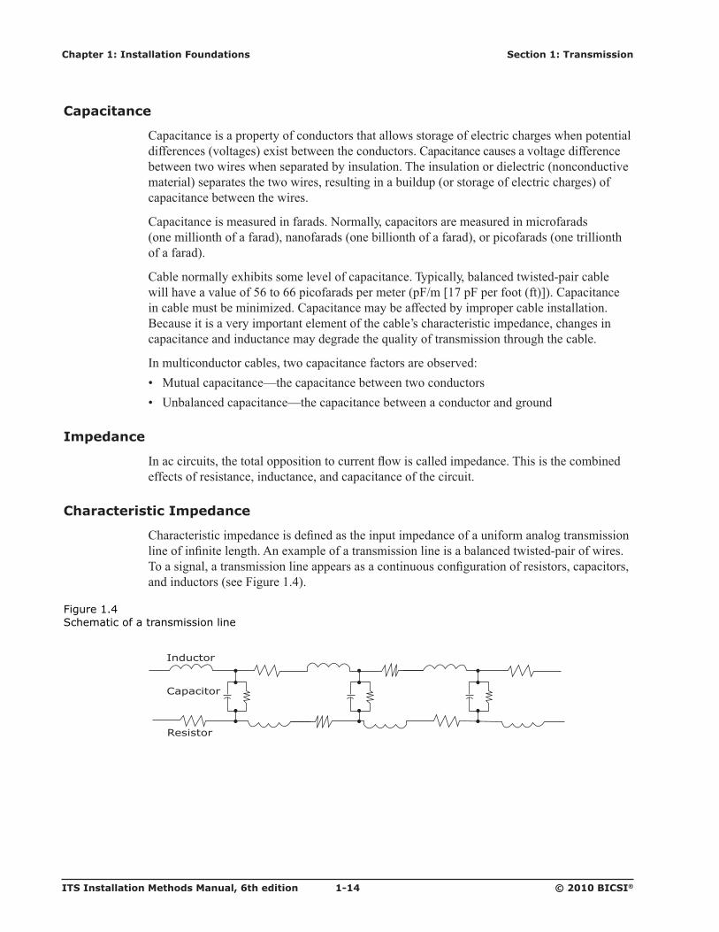
9����� ���� �������������������������� ������� ������������������������������ ������������������������ ����� ���#���"���������� ���������������������������� ��� �������������������������������� �������������������������������� ��������������� ������������ ����������� �������������� ���������0������N�M���
Figure 1.4 Schematic of a transmission line
Inductor
Resistor
Capacitor
Page 20
Section 1: Transmission Chapter 1: Installation Foundations
© 2010 BICSI® 1-15 ITS Installation Methods Manual, 6th edition
Characteristic Impedance, continued
5&����������� ���������������������������� ���� ������������������&������� ��� ������ ���� ������������������ ���������� ��L!� 6� ������ ��������� �������� ������ ��������� ����!� <�� ������ ����� ��������� ����!� ����� ����&���������� �������� �� ����� ����� ������������ ���� ����
9����������������� �������&������ �� ������� ���� ����������������������� ���� ���������� ���0����"�����������7G����NGG�� ����� ��������������������� ���� ���������������� NGG�������� ����� ����NGG��������� ������ �������������� ��������������&������*������
#��������� ���������� ������ ����������� ��������&����������� ������� �� �����������������"�������������������� �������� ��������� � ����� ����������� �������������� ��������������&����������� ����� �����������*��������������������� ���������������������������������������������������� ��
6�� �������� ��� ����������������������������"��� ���������� ���� ���������������� �����"��� ���NGG������_�N;������� �� �N�6'4�� ��� ������ �������OG�^9��=P�`0���
Insertion Loss (Attenuation)
����� ���������� ���� �������L!� ����������������������������� ��������� �������� ����������������� ����$�������������� � ������� ������ ������������&������ ������������ ������ ���� �����!� �������������������������������������������������� �������� �&������������� ���� � ������ ����&�������!� 6������������������������� ���� ��� �����&������*�������#�����*������������ ������������ attenuation increases.!� #������������������� �� ���������������&���� �������� ���������&����� ���� ����'����� � � ���� ���������������&�����������
���������� ����������� ���� ���������������� �� � �������������� � ���� ������ � ��������&������������������������� ������������������ ��������� ���������������������������������� ����transmission systems.
Return Loss
F� ��������������� ����"��������������������� ������������ ����� ������������ �� ������������ �����2�� ����������@���� ��� ������ ��������������������������� ��� �����*���� ���&������� ��������� ���� ���������������� ��� �����������������������NGG������������������������� ���������������������2�� �����$� ������ ������������������� ����&����� �� �������
��������� ������2�� ������������������ ����� ���������������������������� ���� ����� ����������� ������������� ��� ��������������� ���� �������������������2�� ����F�������� ����&����� �����2�� ������������������� �������� ��������������������&�� ����������� �� ���load.
Page 21
ITS Installation Methods Manual, 6th edition 1-16 © 2010 BICSI®
Chapter 1: Installation Foundations Section 1: Transmission
Return Loss, continued
0������������ �������2�� ��������� ���������������������� ���� �����"�� ������ ��� ��������� � ������� ������ ������ �����������&���������������� ����������������������� ������ ��������NGG�����_�N;������� ������������&���� ������������� ������ ������� ������ ���� �� ��������� ��%����� �� ����&������������������������� ��������������������������"���������� �������������� ������������&���� ������� ��������� �������������������� �����������&���� �������������������������"����������� ���������� ��������
������ ����������������������������������������� ��������������� ������������������ ���������� ��������� � �������� ������������2�� ������������������� ��� �������&������������������ �� ��� ������ ���������
Crosstalk
��������� ��� ������������������%����� ������� ��������������������������������� �� �� � ���������� ��������������� �$������� ��������������� ����������������������"��� �� ������������ ������������ �$������ �������?���� �������������#J����9���� �$��������������������� ��� �������������������������������������������� �������������������������&���������� �������������� ��������������
�����&���������� �$�������������������*���������������� ������������� ������ ���� increase is not directly proportional.
����������� ������������� �$���������� ���� ������������ ��� �������������L!� V������������� �$��V5J��!� 0������������ �$��05J��!� #��������� �$��#J��
Near-End Crosstalk (NEXT)
V5J������������������ �������� ������������������������ ������ ���� � �������������� ����� ������������������� � �������������@����V5J������������ ������������� ������ �� ��*������ �� �����������"������� ������������� �������V5J��������� ����� ����M��������������$����������L!� 3����N]�����O!� 3����N]�����7!� 3����N]�����M!� 3����O]�����7!� 3����O]�����M!� 3����7]�����M
Far-End Crosstalk (FEXT)
05J������������������ �������� ������������������������ ������ ���� � �������������� ������������������������������ � �����������������������05J������������� ������������������������� � ������������������������� ��������� ���������&����� ������ ����������� � �������������� ��������05J�������������������"������������������� � ��������� ����������������� ���source ��������� ������ ���
Page 22
Section 1: Transmission Chapter 1: Installation Foundations
© 2010 BICSI® 1-17 ITS Installation Methods Manual, 6th edition
Crosstalk, continued
0������N�;���� �� ���� ��V5J������05J���� ������� ����������V5J������05J������ �"������������������
Figure 1.5 Crosstalk paths
FEXT = Far-end crosstalk NEXT = Near-end crosstalk
��������� ���*��� � ����������� ������������ ����������� ��� ��������� ��������&��� �� ������ ����������� ������� ��������� �������������� �$�����&����
# ���� ���� ������� �$��� ������������#9F0�������������������� ������*����&��������������� �$��5K05J������� �������������� �������� ��������� ������������������ �� ���� ���������������������������������������� � �������������������������� ��������� ���������&������������ ����������� � ��������&����������� ��������#9F0������������������"������������������� � ��������� ����������������� ������������������� ������ ���
����&��������#9F0�&���������������������� ������ ����� ����������������� ��� ���� ������ �� �&���������#9F0���������������������� �������� ����������� ������ ������� �� ������������� ����������� ����������� ������ ��������������� ��� �������� ���05J�� ���������� ���������� ������#9F0�
Pair 2
Far-endload
FEXTpaths
Far-endload
Pair 1
NEXTpaths
Source
Near-endload
Page 23
ITS Installation Methods Manual, 6th edition 1-18 © 2010 BICSI®
Chapter 1: Installation Foundations Section 1: Transmission
Crosstalk, continued
Alien Crosstalk (AXT)
#J����� �������� ��������������������������� ����������������M������������������ �������� ���$������������� � ������� ���������������� ����M���������������������� ���$��or component.
������������&����&����� �����#J���������������� �� ����������� ������ � �������������� �������������������������� �� �� �� �������������� �� ��������������������������� � ��������������� ����������� �����������X8�59�NNPGN��#V��8��#�NN;O��#V��8��#�;=P�9�O���0������N�=������ �� �����"���������������� ���� �� ��� �������� �� ��������� ��*���������������#J�������������������#J������������ ���������������� ��������������������� ������������ ����
������������� ���������� ����%������ ���� �� ����������� ������� �� ���������� ��� �� �������������������������������������������������� ����������� ������� ������������������������������� ��� ��#J���������� ���������������� ��� �� ���������� ��� ��������������������� ������ ��*��������"������������������������� ������for their products.
Figure 1.6 �� �����������������������������������������������������
Page 24
Section 1: Transmission Chapter 1: Installation Foundations
© 2010 BICSI® 1-19 ITS Installation Methods Manual, 6th edition
Crosstalk, continued
Installation Considerations Related to Alien Crosstalk (AXT) and Bundling of Cabling
��������8��������&���� ������������&������������������� ������������ ��� ������� Q08B�3R���&���������������������������� ������������ ��� ��������Q�80�3R������� ������=#8�����5�#������������������� ��� ����������������������� ������ ��� ���� �� ������� ��� �������� ��� �������������������� �������� �����%�������� ���� ���������� ������������������������������� ��� ����������8�������������� �� � ���#J����*������� �� ��������������������� �����������������X8�59�NNPGN��#V��8��#�NN;O��#V��8��#�;=P�9�O��������"��������
B���������&���� ���������� ���������� ��� ��������QB�3R������� ������=#8�����5�#������������������� ��� ���������������������� ������ ������������������������������������� �������� �����%�������� ���� ���������� ������0������� ����������������� ��� �� ��� ��� �� �������������������� ������=#8�����5�#������������������� ��� ��������������� ��������N�N�
Table 1.1 Cable bundling restrictions when cables are produced by different manufacturers
Category 6A/Class EA Category 6A/Class EA and and Higher Cable Bundling Conditions Higher Balanced Twisted- Balanced Twisted- within a Pathway (e.g., Pair Screened/Shielded Pair Unshielded conduit, basket tray) Cabling (e.g., F/UTP, S/FTP) Cabling (e.g., UTP)
9����������������������� � ������� ������ �� ����������� �� ���� ���������� ����� #����� V� ������
9����������������������� � ������� ������������������ ��?���� ��������� ���� ��� ������� ����� � #����� #����
9����������������������� � manufacturers that are ���������� ���� �������� �� ����� � #����� #����
F/UTP = Overall foil screened with unshielded twisted-pair S/FTP = Overall braid screened with foil screened twisted-pair UTP = Unshielded twisted-pair
0���������� ���������������������������� ���������������������N�N�� ��������������������� �� � ���#J����*������� ����������������������� �����������������X8�59�NNPGN��#V��8��#�NN;O��#V��8��#�;=P�9�O��������"�������
Page 25
ITS Installation Methods Manual, 6th edition 1-20 © 2010 BICSI®
Chapter 1: Installation Foundations Section 1: Transmission
Crosstalk, continued
Mixing Category 6A/class EA and Higher Cabling with Lower Performing Cabling
��������8��������&���� �����������08B�3���80�3������� ������=#8�����5�#������������������� ��� ����������������������� ������ ��� ���� �� ������� ��� �������� ��� ����"������ ��������� ����������� �� ������� ���������� ��� ����������������� ���� ���������� ���������������������?���� ��������� ���� ���������� ������������������������������� ��� ���������������� �� � ���#J����*������� ����������������������� �����������������X8�59�NNPGN��#V��8��#�NN;O��#V��8��#�;=P�9�O��������"��������
B���������&���� �����������B�3������� ������=#8�����5�#������������������� ��� ���������������������� ������ ������������������������������� ������=#8�����5�#������������������� ��� ����������������"����� �������������������������� ���� ��������������� �������� ������0������� ����������������� ��� �� ������ �� �������������������� ������=#8�����5�#������������������� ��� �����������������������N�O�
Table 1.2 Mixing category 6A/class EA and higher cabling with lower performing cabling
Category 6A/Class EA Category 6A/Class EA and and Higher Cable Bundling Conditions Higher Balanced Twisted- Balanced Twisted- within a Pathway (e.g., Pair Screened/Shielded Pair Unshielded conduit, basket tray) Cabling (e.g., F/UTP, S/FTP) Cabling (e.g., UTP)
9� ������=#8�����5#������������ ��������"����� �������� ����������������� �� ������ ������� ������������� ���� ���������� ����� #����� V� ������
9� ������=#8�����5#������������ ��������"����� ������� ����������������� �� ����� ����������?���� ������� �� ���� ���������� ����� #����� #����
9� ������=#8�����5#������������ ��������"����� ������� ����������������� �� ������� � �������� ���� ���������� ����� #����� #����
F/UTP = Overall foil screened with unshielded twisted-pair S/FTP = Overall braid screened with foil screened twisted-pair UTP = Unshielded twisted-pair
Page 26
Section 1: Transmission Chapter 1: Installation Foundations
© 2010 BICSI® 1-21 ITS Installation Methods Manual, 6th edition
Nominal Velocity of Propagation (NVP)
�����������&���� ������������ �����VA3��������� ������ ������������ �������������������������� �&�� �� ��������������� ������&�������� ������ ���� � ������������ ������9�� ���� �� ��*������ ������VA3� ���� ������� ������ �����������
Propagation Delay
3������ ������������ ��� ������ ��&����*������������������ ���� ������ ��������������������������� � �� ���� �����0���NGG�����M������������ �����"������������������ ���������������������� �NG�6'4��������� �������������������������������"�����������������������
Delay Skew
<�����$������ ����������������� ���������� ���������� ����� �������� �������� �� ��������� ���� ���������������� ���0���NGG�����M������������ �����"������������������� ����������$���������������� �NG�6'4��������� ������������������This measurement is expressed in nanoseconds.
Insulation
9��������������� ������������������ ������� ������������������������������������� �� ���� ��� �������������� ������� ��������&�� � �������������� ��&���������� ��� ������������������������� ��������� ����� ����&��� ����������&�&���������������������� ������������ characteristics desired for the application and installation environment.
#����� ������������� ������ ����������������������������� ��� ����������������*������������� ��� ��������� ���������������� ����������������*������� ����������������� ����� �&������� ��������������� ��������������������������� ������� ���� ����
��������� ������ ���������� ������������ � �������������4����� ������������������� �� ������� ������ ������������������� ��������������� ���� ���L!� 6� ��������� ��������������!� 9����� ����
6� ��������� ���������������� ��������� ��%������� ������ ��������� ����� ����%�� ����� ���� ���$������
VX�5L� X����������������������������� ������� �������������� ��������������� ���� �� �� ��������� �����&�������������������� �������������� �������� ���&����� ����� ������� ��������� ����
���������� �������������������� ��� ����� �� ������������� � ����$� ������� �������� �����9����� ����������&��������� ��� ������� �����
Page 27
ITS Installation Methods Manual, 6th edition 1-22 © 2010 BICSI®
Chapter 1: Installation Foundations Section 1: Transmission
Pair Twist
������� ���������� �� � ������������*��� ��������������������� ���� ��� �������������������� ���������� ��� ������������������������� ��� ��� ��� ������������ ����� ���� ��� ������������������ ����������&����������������"��� ���=�����G�O;����� ��N;G�����=������������������������������ �������� �� ���� �����������������������&�� ������������������� ���Y���������� ����������� � ��� ��� ���������� ����������� �������������� ������� ��� �������������� ��*������������� ������ �������� �������������������� ������� �������� �������������&����� ��� ���� ���������
3��������������������� ��� ������� ���������������4���� ����� ������� �$������������� �������������� �� � ���������� �����������4�� �������� �����������������&���������� ��� ��������� ���� ������������� ��� ��������������&��������������� ������ ���� ��������� ���� �� ��������� ��������������3���� ��� �����&�������������� ��������� ��������&������������ 0������N�>��������?�� �&�����������4������������ �������
Figure 1.7 Typical balanced twisted-pair cable
Cable jacket
Drain wire
Foil shield
Cable jacket
Unshielded
Shielded
Page 28
Section 1: Transmission Chapter 1: Installation Foundations
© 2010 BICSI® 1-23 ITS Installation Methods Manual, 6th edition
Shielding
Y������� ��� ��������������������������� ���&�&������ ������&���������������&��� ��������������0�������N�P�����N�j���9�� ������� ���������������������������������������Y��$����������������������&����������
The shield is used to:!� F������ ����&����� �������������� �������� �������!� 6�����4�� �������� �����" �����56����� �������������!� 3��&��������������� �� ����
��������������� ��������������� �� ���$������������ �&����&���������� ������������ ������� �������� ������� �������� �&������������ ���� ��������%����������������������� ��������� ���������������������������� ������������������������������������� ������ �����9Y9���
���������%�������� ���� ����������������L!� 0������ ���������$�����������*���������7G�6'4�������������
VX�5L���<������������������ �&��������� ��������� ���� ���������
!� 9�����������������$���������*��������!� ����� ����������$������*��������!� 9Y9������������&�� ��������������*������������������� ��������
Page 29
ITS Installation Methods Manual, 6th edition 1-24 © 2010 BICSI®
Chapter 1: Installation Foundations Section 1: Transmission
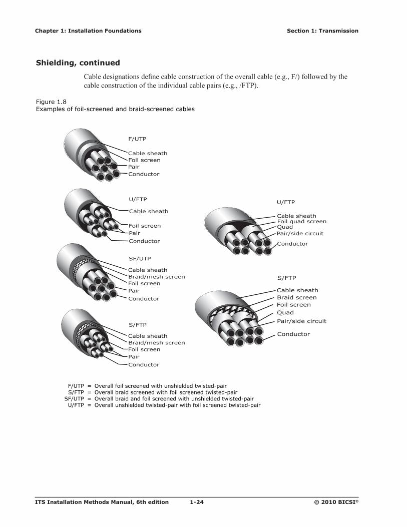
Shielding, continued
9���������� ������������������� ��� ������� ����&���������������08����������� ����������� ��� ������� �������&����������������������80�3��
Figure 1.8 Examples of foil-screened and braid-screened cables
F/UTP = Overall foil screened with unshielded twisted-pair S/FTP = Overall braid screened with foil screened twisted-pair SF/UTP = Overall braid and foil screened with unshielded twisted-pair U/FTP = Overall unshielded twisted-pair with foil screened twisted-pair
Cable sheath
QuadPair/side circuit
Conductor
U/FTP
Foil quad screen
F/UTP
SF/UTP
Cable sheathFoil screenPairConductor
Cable sheathBraid/mesh screenFoil screenPair
Conductor
U/FTP
Cable sheath
Foil screenPair
Conductor
S/FTP
Cable sheathBraid/mesh screenFoil screenPair
Conductor
Cable sheathBraid screenFoil screenQuad
Pair/side circuit
Conductor
S/FTP
Page 30
Section 1: Transmission Chapter 1: Installation Foundations
© 2010 BICSI® 1-25 ITS Installation Methods Manual, 6th edition
Shielding, continued
Figure 1.9 Examples of screened and unscreened balanced twisted-pair cables
F/UTP = Overall foil screened with unshielded twisted-pair S/FTP = Overall braid screened with foil screened twisted-pair SF/UTP = Overall braid and foil screened with unshielded twisted-pair U/FTP = Overall unshielded twisted-pair with foil screened twisted-pair U/UTP = Overall unshielded twisted-pair with unshielded twisted-pair
Cable sheathQuadPair/side circuit
Conductor
U/UTP
Cable sheath
QuadPair/side circuit
Conductor
U/FTP
Foil quad screen
U/UTP
Cable sheathPair
Conductor
F/UTP
Cable sheathFoil screenPairConductor
U/FTP
Cable sheath
Foil screenPair
Conductor
S/FTP
Cable sheathBraid/mesh screenFoil screenPair
Conductor
Cable sheathBraid screenFoil screenQuad
Pair/side circuit
Conductor
S/FTP
SF/UTP
Cable sheathBraid/mesh screenFoil screenPair
Conductor
Page 31
ITS Installation Methods Manual, 6th edition 1-26 © 2010 BICSI®
Chapter 1: Installation Foundations Section 1: Transmission
Coaxial Cables
9��"������������&�� ��������������� ������ � �� � ���������������� ������� ������� ���������� ��������������������&������ ������&���������������� ����������������� ��� ����������� �����&��������������" ������� ������������������� ������� �� ���H�����&���� ��� �� ������&����������� ��������Z� ������������ ������ ��������� �
Hardware
# �������������� ���������� ������� ������&�������� �������������� ��������� ���� ���� ���������� ��� ������������ �������������������� �� ������������������&��� �� ��������� ������������������ ���� ����� ����� ������������9���� �$������������������ ������ ����� �� �� ������������������ ����� ���$������������ ��� ��� �� �������&�����
#��������� ���� ��������$����������������������� ����������� ������� � 8������ ����� ������ ������ ��������� ���&���� ��������� ����� ������������������������������ ���� ���������������� � �������� ������������ ������������������������� ������� ���������������� ����������*������� �������� � �������� ��������*������ � ������� ������������� ��� �� ���������� ���������������*��������������&������?�� �
Page 32
Section 1: Transmission Chapter 1: Installation Foundations
© 2010 BICSI® 1-27 ITS Installation Methods Manual, 6th edition
Optical Fiber Cabling Media
Overview
X� ���������������������������$������������4�� ����� ��� ���������� ������@����������������������� ���$������������*������������������������� ������ ��� ����NGG����7OP�� ��������������� �������� ��� ������������������ ��������������������������� ���� ���� �� �������$��� � ������������������������������������������� ���� ��������� ������������������ ����������������� �$����� ������������� �56����������'���&�����$���������������� ���� ���������������������������������&������� ����������� ������������������������ �� ����������� ����
������������������������ ������������ ��� �������������� ������������������� ���������������������� �� ������������� ������� ���������� ����������?�� ����� �� ����� ������������������� �� ������ ����2������������� ��� �������������������
������������� ������� ���������� ����������������� ������� ���� ������ �������������� ������������� ��������������������������������� ��������������������������� �������������� ��������� ������ ��� ���� �������������� ��������2�� �&����������
X� ��������������������������� ������������������� ������������������� �����������&������� �&������������ ������� ����������������P� ��NN�������� �����q���������������������� ����*��� ��NO;�q���K����� ������ ������&�������������� ������������������� NGG������� ���� ������ ���������� ����������� ����� ���������6� ���������������������������� ����������;G����=O�;�q����� ������������� �NO;�q���������� ������� ��� ��� ������������ ������������������������� ������������������ �������������� ����� ���������������paths or modes.
9����� �� �������������� �� ��;G8NO;�q������=O�;8NO;�q����������������������� ���������������@���� ���;G8NO;�q���������������� ��������� ���=O�;8NO;�q��������������������� ���� ��������� ��������� ������� ���$���� �� ���������������� ���4��� ;G8NO;�q��
������������ ����������� �����������*��� ������������������� ��������������� ������� ����� ������*������������������ �������������� �������������&�������� ��� ������� ����
��������������� �����&�� ����������&�������������������������������"�����&�� ���� ������ ���� �����������K5<������&�� ������&� ������������� ����������A9�5K������� multimode systems.
���������� ���� ���������� ����������� �������� ��� ������� ����������� �����&����� ������������������������ ������� ���� �����Y������ ������� ���� ������� �� �� ��� ������������������ ��������&����� ��������������
Page 33
ITS Installation Methods Manual, 6th edition 1-28 © 2010 BICSI®
Chapter 1: Installation Foundations Section 1: Transmission
Overview, continued
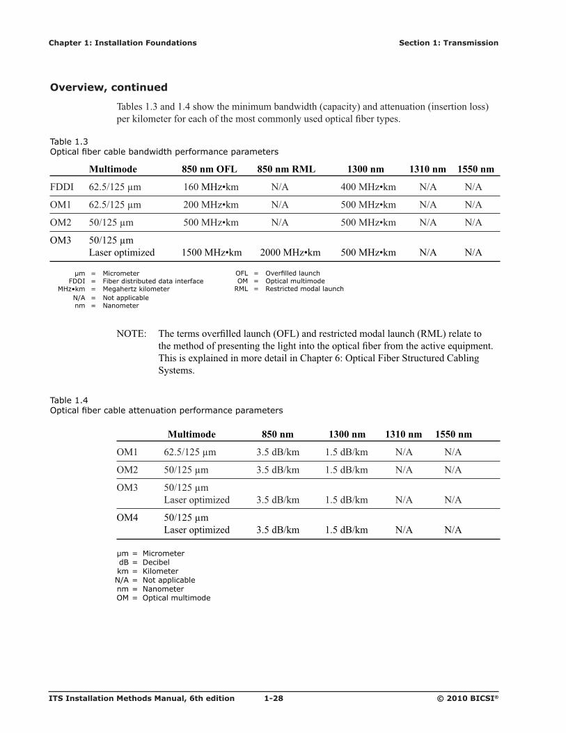
�����N�7�����N�M������ ����������������� ��������� �������� ���� ���������� �������������$���� ��������������� ������ ���������������� �������� �����
Table 1.3 "����������������������#���$����%������������������
Multimode 850 nm OFL 850 nm RML 1300 nm 1310 nm 1550 nm
0<<�� =O�;8NO;�q�� N=G�6'4!$�� V8#� MGG�6'4!$�� V8#� V8#
X6N� =O�;8NO;�q���� OGG�6'4!$�� V8#� ;GG�6'4!$�� V8#� V8#
X6O� ;G8NO;�q�� ;GG�6'4!$�� V8#� ;GG�6'4!$�� V8#� V8#
X67� ;G8NO;�q�� �� K������� ���4��� N;GG�6'4!$�� OGGG�6'4!$�� ;GG�6'4!$�� V8#� V8#�
μm = Micrometer FDDI = Fiber distributed data interface � '*:;��� <� '���$���:���������� N/A = Not applicable nm = Nanometer
VX�5L� ���� ������&�������������X0K��������� ��� ���������������F6K����� �� ��� the �� ������������� ���� ������ ��� �� ����� ������������� ����� �&���*������ ���� ���������"����������������� ������9��� ���=L�X� ����0����� ��� �����9�������� ��� ����
Table 1.4 "���������������������������������%������������������
Multimode 850 nm 1300 nm 1310 nm 1550 nm
X6N� =O�;8NO;�q�� 7�;��Y8$�� N�;��Y8$�� V8#� V8#�
X6O� ;G8NO;�q�� 7�;��Y8$�� N�;��Y8$�� V8#� V8#�
X67� ;G8NO;�q� � K������� ���4��� 7�;��Y8$�� N�;��Y8$�� V8#� V8#
X6M� ;G8NO;�q� � K������� ���4��� 7�;��Y8$�� N�;��Y8$�� V8#� V8#
μm = Micrometer dB = Decibel km = Kilometer N/A = Not applicable nm = Nanometer OM = Optical multimode
� "�>� <� "?�������������$ OM = Optical multimode RML = Restricted modal launch
Page 34
Section 1: Transmission Chapter 1: Installation Foundations
© 2010 BICSI® 1-29 ITS Installation Methods Manual, 6th edition
Bandwidth
��������������� ���������� �����������&������������������ �������� ������������ ��������� �������������������� ������� �����6���������� ����������������� ��������������� 4!$���� ����6'4!$���
������������� ���� ������ ����� ���������� �����&���� ����� ������ ������������������ �������������� ������ ��������� ���������� ������������������� ����� ��� �������������� ��
Dispersion
<������������� ��������������������������� ���� ����������������� ���������� ����������������� ����� ������������ ��������������� ���������� ������&������ � ��������&���������$��� ���������� ����� ������������������������� �����#������������������ ���������������������� ���� ���� ��������� ���Y5F�������������Y������ ����� ������������ ����� � �������������that is the sum of modal dispersion and chromatic dispersion.
Modal Dispersion
6������������������� ������� ����������� ��� ������ ����� ���������� ���������� �����0������N�NG���� ��������������������� �� ������ ���������� ���� ������ ��� �������������������� �������� �� ����� ��������������� ���� ������ ������ ��� ��� �$����� �������������������� ���� ���� ��&������� ������������ ���������� �� ��������&���
Figure 1.10 Modal dispersion
Page 35
ITS Installation Methods Manual, 6th edition 1-30 © 2010 BICSI®
Chapter 1: Installation Foundations Section 1: Transmission
Dispersion, continued
Chromatic Dispersion
9����� ��������������������� � ������ �������������0������N�NN���������������� ��4��� ������ �� ������ ������������� ������������A9�5K�����K5<���������� ����������������� ������������ ������������&���� ������ �������� ������ ���?�� ����� �� ����� ����������������� �������������������� ��������������&���� ���
Y������� �������"���������� ������� ���������� ������������� � �������������������� ���&����� ��������� ��&��� ������� ����� ��������� ������� ���������� �������
6��������������� ����� ����� ����������� ���������������� ����� ������������������� ������������� ���Y5F���������� �������� �&�������� ����������� ���������������������"��� ��������� �������� ���������������������������������� ������� ������� ���
Figure 1.11 Chromatic dispersion
1310 μm
1305 1315
μm = Micrometer
Page 36
Section 1: Transmission Chapter 1: Installation Foundations
© 2010 BICSI® 1-31 ITS Installation Methods Manual, 6th edition
Differential Mode Delay (DMD)
0������N�NO���� �� ��� �������������������������"����������=O�;�q���� ����������������&��������;G�q���������$���������# �������������� ����&����� ����?�� �&������� �������������� ��������������������� � ��� ������ ������������������ ���������� ��������� �������������������� ��������������<6<��
Figure 1.12 Core ����������������������������������
μm = Micrometer n = Refractive index r = Radius
6��������������8����������� ������<6<������������ ����� �� ����� �������������� �����@������������A9�5K� ������ ������� ��� �������������� ����� ������&����� ��������� �� � ���������� ��������&���� � ������ ��� ������������ �����������������������K5<������ �������� ������ �������� �����&��������� ���������� ������������������ ��������������� A9�5K���A9�5K����������������������K#V���&������� ������������� ���������� �
@������������A9�5K� ������ ������ �������������������� �� ���� ���������� ���������� �� ���� ��������� ����'���&������� ������ ������ ��&�������� ������ ����� ����� ��������� ��������� �� �� ������������������������������������������������� �<6<����������� ����� ���������# ���������� ������ ����� ��������� ��������������� ������������ ��@���� ������������� ���������� ��������������� ������������������������ �� ���&�� ������� ��������� ����=O�;����;G�q�������;G�q��������� ���4����� �������� ������������� �������� �����<6<������������������������������� ���������� ���$��
Refractive near field profile of 62.5/125 μm fiber
n(r)
Radius (μm)
-36 -32 -28 -24 -20 16 -12 -8 -4 0 4 8 12 16 20 24 28 32 36
Page 37
ITS Installation Methods Manual, 6th edition 1-32 © 2010 BICSI®
Chapter 1: Installation Foundations Section 1: Transmission
Attenuation
K��� ������������ �������������������?�� ��� ����������� ������������ ������ ������� ��&������� ����� ��������������� ���� �������������������� ��������� ��������������������� ������ ���� ��������� ����������� ��������� ������ �
K������������������� ��������������������������� ������L!� <���� ������������ ������� ���������� �����!� 9������4��&���� �������������� �������� ������������&������ �&���� ������������������ �����!� A���� �������� ����� �������� ����� ��������������������!� 6�������������������������� ���� ������!� 9����� ���� ������ ���������������������������� �� ���$����� ����� ���������
X� ��������� ���� ��������������������������������$���� ����� ���������� ����� ����� �������������� ����� �����&���� ����� ������ ���� ��������� ��������
��������������������������� ������ ��������� ������������������*��� �� ��������������� ����"��� ���� ���� �����������&�������������� ������� �������� ��������������� ��L!� 6��� �������*�� ������������������������ ���%������ ���������������� ������!� B�������������������� �����&������� �
Page 38
Section 2: Professionalism Chapter 1: Installation Foundations
© 2010 BICSI® 1-33 ITS Installation Methods Manual, 6th edition
Professionalism
Overview
����������� �������$������������ �� �������� �� �����������������&��������0��� ���� �������� ���������� ���������*������ �����$��� ���������� � �������������Z���� ������ ������������ �� ����Z��������� ��������*��� ���������������������������� ������ ��
Technical Expertise
���� ���������� ������� ������?�� ���*������ ���������� ���� ����������*����������� ������������� ������� ������ ���������������
F�*������� ����� �������� ���������� �� � ���������� ���������������$����������������� �� ���������������������������������
����������� ���%�������������� ����L!� 9����� ������� ���� ���������!� 9����"��*������ �!� #�&������ ����!� 9��� �� ��������� ����� ��������!� �� ���� �������� �����������������������������!� �� ���� �������&�&������������
Project Objectives
������� ���������������&�������� � ���?����� �����������$���������� �������*������� ������?�� ������������ ����������� ���������������������*������� ��
����������� ���������������������$������� ��L!� Y��$���������� ������?�� ��������?�� ���� ���������!� 3��?�� ����� �����!� ��������������� ���� ������?�� �!� �������� ��$���"��� ��� ��������������!� 9����������������������*��� �� ������?�� �!� 6� ��������� �����*����������� ���������!� #�������� ��������������������� � ����� ������������������ ������!� ������ ����*������� ��!� ���� ����*������� ��!� 5&��� ����������$���������!� F�����$���������������������*������� ��!� � � ����������� �������������������� �� ��������������� ������ �����!� F�*��������� �����
Page 39
ITS Installation Methods Manual, 6th edition 1-34 © 2010 BICSI®
Chapter 1: Installation Foundations Section 2: Professionalism
Project Team Members
#��������� ���������� ������ ������������ ���������� ����� �����������������������4� ������������� �������������������4� �������������������� ������� �������$�
#��������� ������������*������ �� �$��������$��� ��������������� ������L!� 9���� �� �!� �����&�����!� 3��?�� ���������!� 9����$���!� 9�� �����!� 6������ �����!� A������!� ��������!� #������ �� �&�������������� ���!� F���� ����������&������ �� ���!� X ���� �����
Team Member Responsibilities
�������������������� �������� ������*������� �������������� ������� � �$������������ �� ��$����������� ������������������ ��������� ����� ���?��
�������&�&����� �������������&����������� ����������$���� ������� �*��� ������������L!� @�� �����"��� ��z!� @�� ���� ������?�� ���&������� z!� @�� ���� ����"��� ����������z!� @�� ����� ������ ���� ������������������z!� @�� �� �������?�� �������������� �������� ��������������� ������?�� � �� ���������� ��� �������?�� z!� @������������ ������������� ��������������� ����?�z!� ��� ���������� �����"��� ��� ����� ��� ������� �������$���$������������ ��$z!� @�� ������$������� � ���������� ������*����z!� ��� ���������� �����"��� ��� �����&���� �������z!� @�� ���� ������ �������� ����� ���"��� �� ������?�� ���������� � ������� �����&���z
����� ������ �����&����������� �� ��������������� ��� ������������������?�� ���X�����������?�� �� ���������� ������� �������������� �������������� �����������$���������� ��������������� ���� ������ �� ������ �������������� ������������� ����
Page 40
Section 2: Professionalism Chapter 1: Installation Foundations
© 2010 BICSI® 1-35 ITS Installation Methods Manual, 6th edition
Interpersonal Skills and Communication Requirements
������� �� �������������4������$������ ������&������� ��������������� ������� �&������?�� ��������� �� ���� ����� ������������ �� ����������������
Effective Communication Skills
����������� ���%�������������� ����� �������� �&��������� ������������ ����������&������� ������������ ��������&��������� ����&���������� ���
#���������� �&����������� ���� ���������� ���������L!� K�� ���� �� �&�������� �$���� ��������������� ��!� 3��&��������� ��������� ������� � ������?�� �!� F����� � ���&������ ���� �������������������� �����!� #���������� ���� ��������� �&�� ����� ������!� 3���������������� ������� �������&� ��!� ���$� ��������� ����������� �����
5�������������&�&������ ������?�� ��"��� ������������� ����� ���L!� ������!� 9����!� 9�������!� B�������!� ��� ����!� 0���������������� �����������
Page 41
ITS Installation Methods Manual, 6th edition 1-36 © 2010 BICSI®
Chapter 1: Installation Foundations Section 2: Professionalism
Interpersonal Skills and Communication Requirements, continued
����N�;��� �� �������������������������?�� � ����������������� ��� ������������������������������ ���������� ������������� ����������� �� �������������
Table 1.5 Project communications
Position Required Communications
9���� �� �� <���������������� ��������� ����������
�����&���������� ���� ��������������� ��������� �����*��������� �� �� �����$���� �������$����������� ��������� ���
9�� ���������� 3��?�� ����������� �� ����� ������� ������������ �������������?�� ���������� �������������� ��������� �� ������������������ � ��������� �&��������������������*������� ���������� ��������� ��*������� ��
9�� ��� ���� 9������� ����������������������� ��������������������� � �������������*��������� ����
6������ ������� 3��?�� �������������&��������������&������ ������ &��������������������� �������� ������ ������� ������������*������ ���*������� �
#������ �� �&�� W����� ���������������������&��������������� ��� � �� ��������������$��������
X ���� ������ @��$���������������� ����������������� ������������� � ���$��������� ����������������������Q��� ����R�������������� ���� ������������ ������������
F���� �������� 3���� ������������ ����������� ���������������������cation ��&������ �� ���
#���� ����������������� ��� ��%�������������� ����������L!� #���&��������� ���� ���������������������������� ����� ������������!� <����� ���� ������������������ ����������������" ���������������� ��������&���������������!� �� �� �������� �������������� ��� ���������� �� ������������
9�� ������������ ��������� ����������� ����H�����&������������� �� ������������������dependent on customers.
VX�5L� Y���������� ��� ������������������������ ������������ �����"������������ ��������� ��������� ���� ������ �������������� ����
Page 42
Section 2: Professionalism Chapter 1: Installation Foundations
© 2010 BICSI® 1-37 ITS Installation Methods Manual, 6th edition
Interpersonal Skills and Communication Requirements, continued
Customer Relations
9�� ������������������&�� ����������� ����������� ��������� ������������������ �� ���������6�� ����� ���������������������� �����$����� �� ���� �� ������ ����%��������� 9�� �������*������� �������"��� � �������� ����������4���������������������� ����� manner.
���������������������� ���������� �����������?������ ��������������� ����9�� ������ ���������������� �����&������ ������������ ���������������� ����$�������� ��� ��9��� �� �������?����� ������ ������&�����"����������� ��������&������������� �������������� ��������%����������� ���� ���������� �������� ������ ��$����������� ����������� �� �� themselves from their competition.
��� ������ �� ������������� �������������������� ��������������������� �� �� � ������ ����������� �� �����������$������� ���������������� ���������� ����������&�����������$������� ���������� �� �� ���� ��������� ������ ��������������������� �� �� � ������� ��������$���� ��������������� �� ���� ������������� ����������
� ������� ��� ������������ ������������� ������������������������� ����&���� ������$����#��������� �������������������������������������$��� ��������� ������������� ���������$���������&���� ����������&�������������� � ���������������� �������������
Customer Perception
#�� �������� ���������� � �&����������������������������������������� �������������� �������������� ������ ��������� ����� ��������������� ������ �����
5� �������� �&��������� �&����������������������������� ���� ������ �NG� ��N;����������������� ���� ����������������� ������� ����������%���� ��� ���� � ������&��� ������������ ��������������� �&����� ������������
Because of this, it is important to:!� 6�$�������������������� �&����� ������������!� 6��� ������������������������� ��� �����
������������������ �����������&���������������������&������� �� �������� ��� ������L!� Y�����������!� ��������&����!� 9��������������
Page 43
ITS Installation Methods Manual, 6th edition 1-38 © 2010 BICSI®
Chapter 1: Installation Foundations Section 2: Professionalism
Interpersonal Skills and Communication Requirements, continued
0������N�N7���� �� ���������������� ����������� �����������$������������������ ���������� ������ �� ������ ������Y��������������$��� �������� ��������������������� ��� �������&�������������������������
Figure 1.13 Communications perceptions
@���� �$������ �� ������ �������� ��� ��������� ��� �������&�������������������������������������������� �����@������������� ������ �� ������ ����������� ����� ������������� ���� ������ ������ �������� ������� ��������������������������� ��������������������� ������������������� ���������������������������� �� ���������� ������������������������
� ��������� �� � �������� ���� ��� ���������&����� ������������������ �$������ ����������������������������� ����&������ ����������� ������ �������� �&����� �������������� ������&�����situation.
Feedback and Follow-Through
0�����$���������� �����������$��� ������� �&����� ��������������$������ ����������������� �������� ���$�� �����������#����� �� ������������������������� �������� ��� �� ���������� ���%�������&������������ ���
����������������� ���������� ������� �����?�� ���� ������� ��������� �� � �������������� ������ ��������� ��������������������4������������������ ��� ������������ ��������� � ���� ��all attendees.
@�����������������������������������$�������� ������������� �� ������ ��������� ���������� ���%��������4� ���������������� ���%������� ���������� ������� �� ������ ��� ��� ��protects reputation, and helps to ensure that time and resource commitments are met.
Professional Appearance
����������� ���%������������������� �� �� ������ �����������$��������������&��������� � � ������� � ���*��� ����� ������$� ���������������#������������� ������������ ������ ��� ��$� ��������������
����������� ������� ��������4�� �� ���������������������������������� ���� �� ����� �� ��������� �&��������� �&���"��� � ������#��������4������� ����������������������� �������&�������� ��� ����� �������������� � ��������� ��������� �����������4� �����'�&���� ������������������� ������ ���*������ ������� ���� �� �������
VX�5L� F����� ��9��� ���OL����� ��3��������������������� ������� ����&�����equipment and safety considerations.
Tone of voice38%
Body language55%
Words7%
Page 44
Section 2: Professionalism Chapter 1: Installation Foundations
© 2010 BICSI® 1-39 ITS Installation Methods Manual, 6th edition
Appendix: Conductor Size
����N�=��������������������#@U������ �����
Table 1.6 Conductor size
Standard 1 Mil Conductor Conductor Conductor dc Resistance dc Resistance of an Size/mm Size/in CSA Sizes (ohms per (ohms per 1 m AWG Inch Diameter Diameter mm2 mm2 305 m [1000 ft]) [39 in])
� M8G� M=G�GGG� NN�=PM� G�M=� NG>�OO� NOG� G�G;� G�GGGN=MGMO
� 78G� MGj�=MO� NG�MG;� G�MN� P;�G7� j;� G�G=� G�GGGNj=P;
� O8G� 7=M�>j>� j�O==� G�7=;� =>�M7� >G� G�GP� G�GGGO=OM=>
� N8G� 7OM�P=N� P�O;N� G�7O;� ;7�MP� >G� G�NG� G�GGG7OPGPM
� N� OPj�Oj>� >�7MP� G�OPj� MO�MN� ;G� G�N7� G�GGGMO=;Gj
� O� O;>�=O=� =�;MM� G�O;P� 77�=7� 7;� G�N=� G�GGG;OMj7M
� 7� OOj�MO7� ;�PO>� G�OOj� O=�=>� 7;� G�OG� G�GGG=;=N=P
� M� OGM�7G>� ;�NPj� G�OGM;� ON�N;� O;� G�O;� G�GGGPOGON
� ;� NPN�jMN� M�=ON� G�NPO� N=�>>� O;� G�7G� G�GGGjPMO;O
� =� N=O�GO7� M�NN;� G�N=O� N7�7G� N=� G�M� G�GGN7NO77=
� >� NMM�OP;� 7�==;� G�NMM� NG�;;� N=� G�;� G�GGN=MGMO
� P� NOP�MjG� 7�O=M� G�NOP� P�7>� NG� G�=� G�GGNj=P;GM
� j� NNM�MOM� O�jG=� G�NNM� =�=7� NG� G�P� G�GGO=OM=>O
� NG� NGN�Pj>� O�;PP� G�NGO� ;�O=� =� N�G� G�GG7OPGPM
� NN� jG�>MO� O�7G;� G�GjN� M�N>� =� N�7� G�GGMO=;GjO
� NO� PG�PGP� O�G;7� G�GPN� 7�7N� M� N�=� G�GG;OMj7MM
� N7� >N�j=O� N�POP� G�G>O� O�=O� M� O�G� G�GG=;=N=P
� NM� =M�GPM� N�=OP� G�G=M� O�GP� O�;� O�;� G�GGPOGON
� N;� ;>�G=P� N�M;G� G�G;>� N�=;� O�;� 7�O� G�GNGMjP=PP
� N=� ;G�PON� N�OjN� G�G;N� N�7N� N�;� M�G� G�GN7NO77=
� N>� M;�O;>� N�N;G� G�GM;� N�GM� N�;� ;�G� G�GN=MGMNjj
� NP� MG�7G7� N�GOM� G�GMG7� G�PO� N� =�M� G�GOGjj>7>;
� Nj� 7;�PjN� G�jNO� G�G7;j� G�=;� N� P�N� G�GO=;>MPG7
Page 45
ITS Installation Methods Manual, 6th edition 1-40 © 2010 BICSI®
Chapter 1: Installation Foundations Section 2: Professionalism
Conductor size, continued
Table 1.6, continued Conductor size
Standard 1 Mil Conductor Conductor Conductor dc Resistance dc Resistance of an Size/mm Size/in CSA Sizes (ohms per (ohms per 1 m AWG Inch Diameter Diameter mm2 mm2 305 m [1000 ft]) [39 in])
� OG� 7N�j=N� G�PNO� G�G7O� G�;O� N� NG�N� G�G77N7=MP7
� ON� OP�M=O� G�>O7� G�GOP;� G�MN� G�;� NO�P� G�GMNjjM>;N
� OO� O;�7M>� G�=MM� G�GO;7� G�77� ����V� ��� N=�O� G�G;7NMj=G=
� O7� OO�;>O� G�;>7� G�GOO=� G�O=� ����V� ��� OG�7� G�G===GNG;
� OM� OG�NGN� G�;NN� G�GOGN� G�OG� ����V� ��� O;�>� G�GPM7N>;P;
� O;� N>�jGG� G�M;;� G�GN>j� G�N=� ����V� ��� 7O�M� G�NG=OjjON7
� O=� N;�jMN� G�MG;� G�GN;j� G�N7� ����V� ��� MN�G� G�N7M;NMM7=
� O>� NM�Nj=� G�7=N� G�GNMO� G�NG� ����V� ��� ;N�M� G�N=P=7;N>N
AWG = American wire gauge CSA = Cross-sectional area dc = Direct current ft = Foot in = Inch m = Meter mil = Millionth mm = Millimeter mm
2 = Square millimeter
VX�5L� 3����������������������� ���&����4�������G�;���O. 9�� ������������������ �����&����4�������G�;���O.
Page 46
Section 2: Professionalism Chapter 1: Installation Foundations
© 2010 BICSI® 1-41 ITS Installation Methods Manual, 6th edition
References
#��������V� ������ ��������X�����4� ���8������������ ���������� ���#������ �����#V��8��#�;=P�9�O� Balanced Twisted-Pair Telecommunications Cabling and Components Standard��#���� ����A#L������������� ���������� ���#������ �����OGGj�
———. #V��8��#�;=P�9�7��Optical Fiber Cabling Components Standard��#���� ����A#L������������� ���������� ���#������ �����OGGj�
———. #V��8��#�NN;O��Requirements for Field Test Instruments and Measurements for Balanced Twisted-Pair Cabling��#���� ����A#L������������� ���������� ���#������ �����OGGj�
Y�9��®. Outside Plant Design Reference Manual��M �����������L�Y�9����OGG>�
———. Telecommunications Distribution Methods Manual��NO �����������L�Y�9����OGGj�
�� ���� �����X�����4� ��������� �������4� ���8�� ���� �����5�� �� ��������9������������X8�59�NNPGN���Information Technology—Generic Cabling for Customer Premises. O�������U���&������ 4�����L��� ���� �����X�����4� ��������� �������4� ���8�� ���� �����5�� ��� ��������9�����������OGGO�
� ��������#�� ����8� ��������V���\�������#�8V\��Oj=>��Optical Fibre Communication Cabling Systems Safety. ��������#�� ����8@���� ����V���\�����L�� ��������#�� ����8� ��������V���\�������OGNG�