CHAPTER 1-1 Cisco ONS 15454 DWDM Reference Manual, R9.1 78-18887-02 1 Shelf Assembly Hardware This chapter provides a description of Cisco ONS 15454 hardware for the ANSI and ETSI shelf assemblies. For card descriptions, see Chapter 2, “Common Control Cards,” Chapter 3, “Optical Service Channel Cards,” Chapter 4, “Optical Amplifier Cards,” Chapter 5, “Multiplexer and Demultiplexer Cards,” Chapter 8, “Optical Add/Drop Cards,” or Chapter 10, “Transponder and Muxponder Cards.” To install equipment, refer to the “Install the Shelf and Common Control Cards” chapter in the Cisco ONS 15454 DWDM Procedure Guide. Note Unless otherwise specified, “ONS 15454” refers to both ANSI and ETSI shelf assemblies. Chapter topics include: • 1.1 Overview, page 1-2 • 1.2 ONS 15454 ANSI Rack Installation, page 1-3 • 1.3 ONS 15454 ETSI Rack Installation, page 1-6 • 1.4 FlexLayer and Y-Cable Protection, page 1-9 • 1.5 Typical DWDM Rack Layouts, page 1-19 • 1.6 Front Door, page 1-21 • 1.7 ONS 15454 ANSI Backplane Covers, page 1-28 • 1.8 ONS 15454 ETSI Front Mount Electrical Connection, page 1-32 • 1.9 ONS 15454 ANSI Alarm Expansion Panel, page 1-32 • 1.10 Ethernet Adapter Panel, page 1-37 • 1.11 Filler Card, page 1-39 • 1.12 Cable Routing and Management, page 1-40 • 1.13 Fan-Tray Assembly, page 1-50 • 1.14 Power and Ground Description, page 1-54 • 1.16 ONS 15454 ANSI Alarm, Timing, LAN, and Craft Pin Connections, page 1-55 • 1.17 Cards and Slots, page 1-60 Note The Cisco ONS 15454 shelf assemblies are intended for use with telecommunications equipment only.
Transcript
78-18887-02
C H A P T E R 1
Shelf Assembly Hardware
This chapter provides a description of Cisco ONS 15454 hardware for the ANSI and ETSI shelf assemblies. For card descriptions, see Chapter 2, “Common Control Cards,” Chapter 3, “Optical Service Channel Cards,” Chapter 4, “Optical Amplifier Cards,” Chapter 5, “Multiplexer and Demultiplexer Cards,” Chapter 8, “Optical Add/Drop Cards,” or Chapter 10, “Transponder and Muxponder Cards.” To install equipment, refer to the “Install the Shelf and Common Control Cards” chapter in the Cisco ONS 15454 DWDM Procedure Guide.
Note Unless otherwise specified, “ONS 15454” refers to both ANSI and ETSI shelf assemblies.
Chapter topics include:
• 1.1 Overview, page 1-2
• 1.2 ONS 15454 ANSI Rack Installation, page 1-3
• 1.3 ONS 15454 ETSI Rack Installation, page 1-6
• 1.4 FlexLayer and Y-Cable Protection, page 1-9
• 1.5 Typical DWDM Rack Layouts, page 1-19
• 1.6 Front Door, page 1-21
• 1.7 ONS 15454 ANSI Backplane Covers, page 1-28
• 1.8 ONS 15454 ETSI Front Mount Electrical Connection, page 1-32
• 1.9 ONS 15454 ANSI Alarm Expansion Panel, page 1-32
• 1.10 Ethernet Adapter Panel, page 1-37
• 1.11 Filler Card, page 1-39
• 1.12 Cable Routing and Management, page 1-40
• 1.13 Fan-Tray Assembly, page 1-50
• 1.14 Power and Ground Description, page 1-54
• 1.16 ONS 15454 ANSI Alarm, Timing, LAN, and Craft Pin Connections, page 1-55
• 1.17 Cards and Slots, page 1-60
Note The Cisco ONS 15454 shelf assemblies are intended for use with telecommunications equipment only.
1-1Cisco ONS 15454 DWDM Reference Manual, R9.1
Chapter 1 Shelf Assembly Hardware1.1 Overview
Caution Unused card slots should be filled with a blank faceplate (Cisco P/N 15454-BLANK for ANSI shelves and 15454E-BLANK for ETSI shelves). The blank faceplate ensures proper airflow when operating the ONS 15454 without the front door attached, although Cisco recommends that the front door remain attached.
1.1 OverviewThis section provides an introduction to the Cisco ONS 15454 ANSI and the Cisco ONS 15454 ETSI.
Install the ONS 15454 in compliance with your local and national electrical codes:
• United States: National Fire Protection Association (NFPA) 70; United States National Electrical Code.
• Canada: Canadian Electrical Code, Part I, CSA C22.1.
• Other countries: If local and national electrical codes, are not available, refer to IEC 364, Part 1 through Part 7.
1.1.1 Cisco ONS 15454 ANSIWhen installed in an equipment rack, the ONS 15454 ANSI assembly is typically connected to a fuse and alarm panel to provide centralized alarm connection points and distributed power for the ONS 15454 ANSI. Fuse and alarm panels are third-party equipment and are not described in this documentation. If you are unsure about the requirements or specifications for a fuse and alarm panel, consult the user documentation for the related equipment. The front door of the ONS 15454 ANSI allows access to the shelf assembly, fan-tray assembly, and fiber-storage area. The backplanes provide access to alarm contacts, external interface contacts, power terminals, and BNC/SMB connectors.
You can mount the ONS 15454 ANSI in a 19- or 23-inch rack (482.6 or 584.2 mm). The shelf assembly weighs approximately 55 pounds (24.94 kg) with no cards installed.
The ONS 15454 ETSI is powered using -48 VDC power. Negative and return power terminals are connected via the MIC-A/P and the MIC-C/T/P FMECs. The ground terminal is connected via the 2-hole grounding lug.
Note The ONS 15454 ANSI is designed to comply with Telcordia GR-1089-CORE Type 2 and Type 4. Install and operate the ONS 15454 ANSI only in environments that do not expose wiring or cabling to the outside plant. Acceptable applications include Central Office Environments (COEs), Electronic Equipment Enclosures (EEEs), Controlled Environment Vaults (CEVs), huts, and Customer Premise Environments (CPEs).
1.1.2 Cisco ONS 15454 ETSIWhen installed in an equipment rack, the ONS 15454 ETSI assembly is typically connected to a fuse and alarm panel to provide centralized alarm connection points and distributed power for the ONS 15454 ETSI. Fuse and alarm panels are third-party equipment and are not described in this documentation. If you are unsure about the requirements or specifications for a fuse and alarm panel, consult the user documentation for the related equipment. The front door of the ONS 15454 ETSI allows
1-2Cisco ONS 15454 DWDM Reference Manual, R9.1
78-18887-02
Chapter 1 Shelf Assembly Hardware1.2 ONS 15454 ANSI Rack Installation
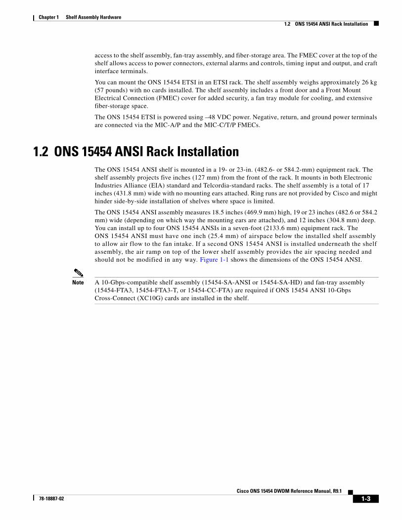
access to the shelf assembly, fan-tray assembly, and fiber-storage area. The FMEC cover at the top of the shelf allows access to power connectors, external alarms and controls, timing input and output, and craft interface terminals.
You can mount the ONS 15454 ETSI in an ETSI rack. The shelf assembly weighs approximately 26 kg (57 pounds) with no cards installed. The shelf assembly includes a front door and a Front Mount Electrical Connection (FMEC) cover for added security, a fan tray module for cooling, and extensive fiber-storage space.
The ONS 15454 ETSI is powered using –48 VDC power. Negative, return, and ground power terminals are connected via the MIC-A/P and the MIC-C/T/P FMECs.
1.2 ONS 15454 ANSI Rack Installation The ONS 15454 ANSI shelf is mounted in a 19- or 23-in. (482.6- or 584.2-mm) equipment rack. The shelf assembly projects five inches (127 mm) from the front of the rack. It mounts in both Electronic Industries Alliance (EIA) standard and Telcordia-standard racks. The shelf assembly is a total of 17 inches (431.8 mm) wide with no mounting ears attached. Ring runs are not provided by Cisco and might hinder side-by-side installation of shelves where space is limited.
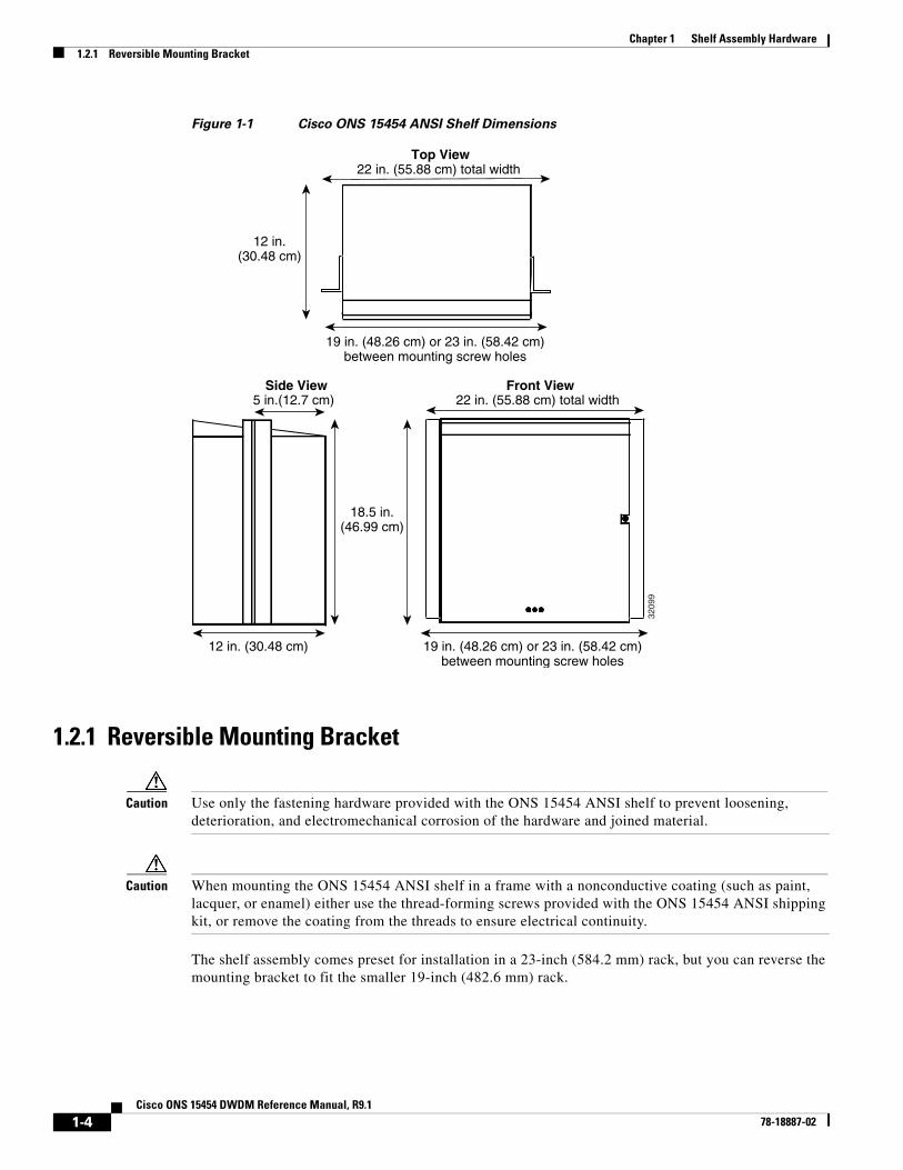
The ONS 15454 ANSI assembly measures 18.5 inches (469.9 mm) high, 19 or 23 inches (482.6 or 584.2 mm) wide (depending on which way the mounting ears are attached), and 12 inches (304.8 mm) deep. You can install up to four ONS 15454 ANSIs in a seven-foot (2133.6 mm) equipment rack. The ONS 15454 ANSI must have one inch (25.4 mm) of airspace below the installed shelf assembly to allow air flow to the fan intake. If a second ONS 15454 ANSI is installed underneath the shelf assembly, the air ramp on top of the lower shelf assembly provides the air spacing needed and should not be modified in any way. Figure 1-1 shows the dimensions of the ONS 15454 ANSI.
Note A 10-Gbps-compatible shelf assembly (15454-SA-ANSI or 15454-SA-HD) and fan-tray assembly (15454-FTA3, 15454-FTA3-T, or 15454-CC-FTA) are required if ONS 15454 ANSI 10-Gbps Cross-Connect (XC10G) cards are installed in the shelf.
Caution Use only the fastening hardware provided with the ONS 15454 ANSI shelf to prevent loosening, deterioration, and electromechanical corrosion of the hardware and joined material.
Caution When mounting the ONS 15454 ANSI shelf in a frame with a nonconductive coating (such as paint, lacquer, or enamel) either use the thread-forming screws provided with the ONS 15454 ANSI shipping kit, or remove the coating from the threads to ensure electrical continuity.
The shelf assembly comes preset for installation in a 23-inch (584.2 mm) rack, but you can reverse the mounting bracket to fit the smaller 19-inch (482.6 mm) rack.
Front ViewSide View
Top View
18.5 in.(46.99 cm)
12 in. (30.48 cm)
12 in.(30.48 cm)
5 in.(12.7 cm)
22 in. (55.88 cm) total width
19 in. (48.26 cm) or 23 in. (58.42 cm)between mounting screw holes
22 in. (55.88 cm) total width
19 in. (48.26 cm) or 23 in. (58.42 cm)between mounting screw holes
3209
9
1-4Cisco ONS 15454 DWDM Reference Manual, R9.1
78-18887-02
Chapter 1 Shelf Assembly Hardware1.2.2 Mounting a Single Node
1.2.2 Mounting a Single NodeMounting the ONS 15454 ANSI shelf in a rack requires a minimum of 18.5 inches (469.9 mm) of vertical rack space and one additional inch (25.4 mm) for air flow. To ensure the mounting is secure, use two to four #12-24 mounting screws for each side of the shelf assembly. Figure 1-2 shows the rack mounting position for the ONS 15454 ANSI shelf.
Figure 1-2 Mounting an ONS 15454 ANSI Shelf in a Rack
Two people should install the shelf assembly; however, one person can install it using the temporary set screws included. The shelf assembly should be empty for easier lifting. The front door can also be removed to lighten the shelf assembly.
1.2.3 Mounting Multiple NodesMost standard (Telcordia GR-63-CORE, 19-inch [482.6-mm] or 23-inch [584.2-mm]) seven-foot (2.133-m) racks can hold four ONS 15454 ANSI shelves and a fuse and alarm panel. However, unequal flange racks are limited to three ONS 15454 ANSI shelves and a fuse and alarm panel, or four ONS 15454 ANSI shelves using a fuse and alarm panel from an adjacent rack.
If you are using the external (bottom) brackets to install the fan-tray air filter, you can install three shelf assemblies in a standard seven-foot (2.133-m) rack. If you are not using the external (bottom) brackets, you can install four shelf assemblies in a rack. The advantage of using the bottom brackets is that you can replace the filter without removing the fan tray.
FAN FAILCRIT
MAJMIN
Equipment rack
Universalear mounts(reversible)
3939
2
1-5Cisco ONS 15454 DWDM Reference Manual, R9.1
78-18887-02
Chapter 1 Shelf Assembly Hardware1.2.4 ONS 15454 ANSI Bay Assembly
1.2.4 ONS 15454 ANSI Bay AssemblyThe Cisco ONS 15454 ANSI bay assembly simplifies ordering and installing the ONS 15454 ANSI shelf because it allows you to order shelf assemblies preinstalled in a seven-foot (2,133 mm) rack. The bay assembly is available in a three- or four-shelf configuration. The three-shelf configuration includes three ONS 15454 ANSI shelf assemblies, a prewired fuse and alarm panel, and two fiber-storage trays. The four-shelf configuration includes four ONS 15454 ANSI shelf assemblies and a prewired fuse and alarm panel. You can order optional fiber channels with either configuration. Installation procedures are included in the Unpacking and Installing the Cisco ONS 15454 Four-Shelf and Zero-Shelf Bay Assembly document that ships with the bay assembly.
1.3 ONS 15454 ETSI Rack Installation The ONS 15454 ETSI shelf assembly (15454-SA-ETSI) is mounted in a 600 x 600-mm (23-inch) or 600 x 300-mm (11.8-inch) equipment cabinet/rack. The shelf assembly projects 240 mm (9.45 inches) from the front of the rack. It mounts in ETSI-standard racks. The shelf assembly is a total of 435 mm (17.35 inches) wide with no mounting ears attached. Ring runs are not provided by Cisco and might hinder side-by-side installation of shelves where space is limited.
The ONS 15454 ETSI shelf assembly measures 616.5 mm (24.27 inches) high, 535 mm (21.06 inches) wide, and 280 mm (11.02 inches) deep. You can install up to three ONS 15454 ETSI shelves in a seven-foot (2133.6 mm) equipment rack. The ONS 15454 ETSI must have one inch (25.4 mm) of airspace below the installed shelf assembly to allow air flow to the fan intake. If a second ONS 15454 ETSI is installed below the first shelf assembly, an ETSI air ramp unit must be assembled between the two shelves to ensure adequate air flow.
Figure 1-3 provides the dimensions of the ONS 15454 ETSI shelf assembly.
Caution The standard ETSI racks can hold three ONS 15454 ETSI shelf assemblies and two air ramps. When mounting a shelf assembly in a partially filled rack, load the rack from the bottom to the top with the heaviest component at the bottom of the rack. If the rack is provided with stabilizing devices, install the stabilizers before mounting or servicing the unit in the rack.
Caution The ONS 15454 ETSI must have 1 inch (25.4 mm) of airspace below the installed shelf assembly to allow air flow to the fan intake. The air ramp (the angled piece of sheet metal on top of the shelf assembly) provides this spacing and should not be modified in any way.
1-6Cisco ONS 15454 DWDM Reference Manual, R9.1
78-18887-02
Chapter 1 Shelf Assembly Hardware1.3.1 Mounting a Single Node
Figure 1-3 ONS 15454 ETSI Shelf Assembly Dimensions
1.3.1 Mounting a Single NodeThe ONS 15454 ETSI requires 616.5 mm (24.24 inch) minimum of vertical rack space and 25 mm (1 inch) below the installed shelf assembly to allow air flow to the fan intake. If a second ONS 15454 ETSI is installed above a shelf assembly, the air ramp between the shelves provides space for air flow. To ensure the mounting is secure, use two to four M6 mounting screws for each side of the shelf assembly. A shelf assembly should be mounted at the bottom of the rack if it is the only unit in the rack.
Figure 1-4 shows the rack mounting position for the ONS 15454 ETSI shelf.
Figure 1-4 Mounting an ONS 15454 ETSI Shelf in a Rack
Two people should install the shelf assembly; however, one person can install it using the temporary set screws included. The shelf assembly should be empty for easier lifting. The front door can also be removed to lighten the shelf assembly.
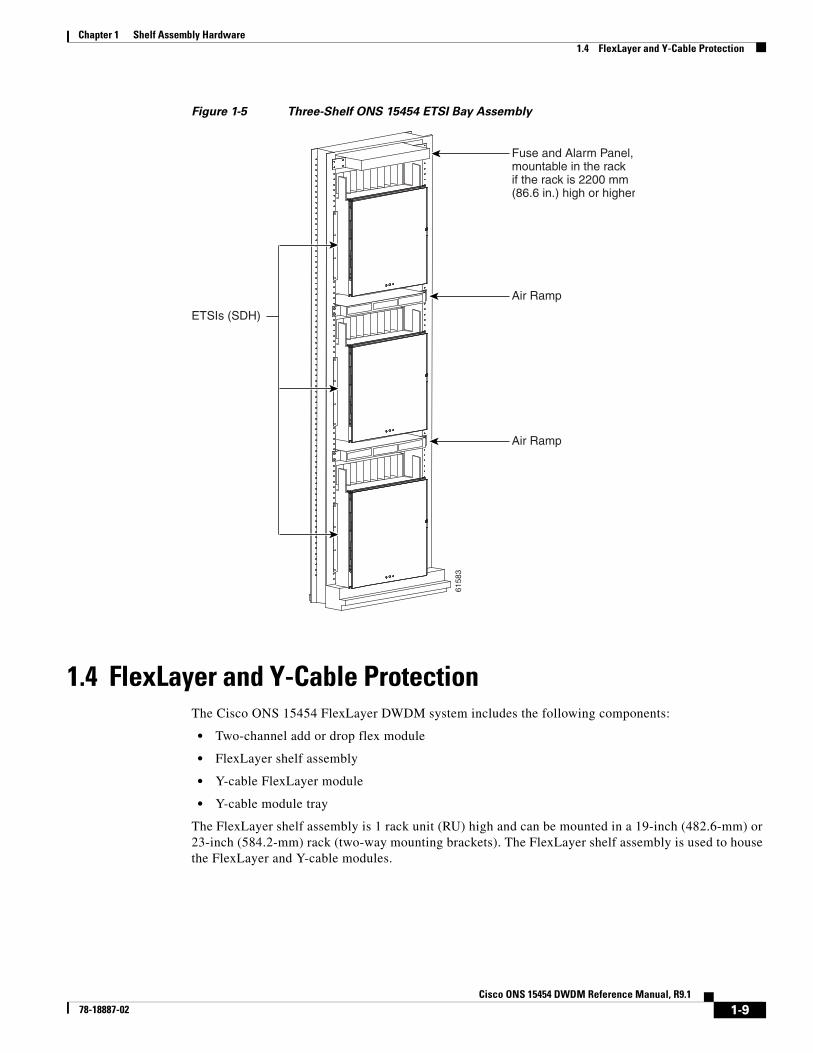
1.3.2 Mounting Multiple NodesMost standard (Telcordia GR-63-CORE, 23-inch [584.2 mm]) seven-foot (2,133 mm) racks can hold three ONS 15454 ETSI shelves, two air ramps, and a fuse and alarm panel. Figure 1-5 shows a three-shelf ONS 15454 ETSI bay assembly.
6124
0
FAN FAILCRIT
MAJMIN
Equipment rack
1-8Cisco ONS 15454 DWDM Reference Manual, R9.1
78-18887-02
Chapter 1 Shelf Assembly Hardware1.4 FlexLayer and Y-Cable Protection
Figure 1-5 Three-Shelf ONS 15454 ETSI Bay Assembly
1.4 FlexLayer and Y-Cable ProtectionThe Cisco ONS 15454 FlexLayer DWDM system includes the following components:
• Two-channel add or drop flex module
• FlexLayer shelf assembly
• Y-cable FlexLayer module
• Y-cable module tray
The FlexLayer shelf assembly is 1 rack unit (RU) high and can be mounted in a 19-inch (482.6-mm) or 23-inch (584.2-mm) rack (two-way mounting brackets). The FlexLayer shelf assembly is used to house the FlexLayer and Y-cable modules.
6158
3
Fuse and Alarm Panel,mountable in the rackif the rack is 2200 mm(86.6 in.) high or higher
1.4.1 FlexLayer ModulesThe two-channel add/drop FlexLayer module is a completely passive unidirectional component that allows the insertion or the extraction of two channels within the ONS 15454 channel plan. This module is used only in point-to-point, one-channel, amplified system configurations.
Sixteen specific modules are available to cover the whole 32-channel bandwidth. Table 1-1 shows how the FlexLayer add/drop modules are grouped in relation to the supported channels.
Table 1-1 ONS 15454 100-GHz Channel Plan
ITU Channel ID Frequency (THz) Wavelength (nm)Two-Channel A/D Flex Module
Figure 1-6 shows the module functional block diagram. In Figure 1-6, the signal flows from left to right when the card is used as a drop component and from right to left when the module is used as an add component.
When the module is used as a drop component, the wave-division multiplexing (WDM) composite signal coming from the DROP-COM-RX port is filtered sequentially by two filters and the filtered channels are dropped at the two DROP-CH-TX ports. The rest of the WDM composite signal is sent to the DROP-COM-TX port. A two-percent tap coupler, DROP-MON, is used to monitor the input WDM composite signal.
When the module is used as an add component, the added channels coming from the two ADD-CH-RX ports are combined with the WDM composite signal coming from the ADD-COM-RX port. The multiplexed WDM composite signal is sent to the ADD-COM-TX port. A two-percent tap coupler, ADD-MON, is used to monitor the multiplexed WDM composite signal.
24 58.1 192.4 1558.17 15216-FLB-2-58.9=
23 58.9 192.3 1558.98
22 59.7 192.2 1559.79 15216-FLB-2-60.6=
21 60.6 192.1 1560.61
Table 1-1 ONS 15454 100-GHz Channel Plan (continued)
ITU Channel ID Frequency (THz) Wavelength (nm)Two-Channel A/D Flex Module
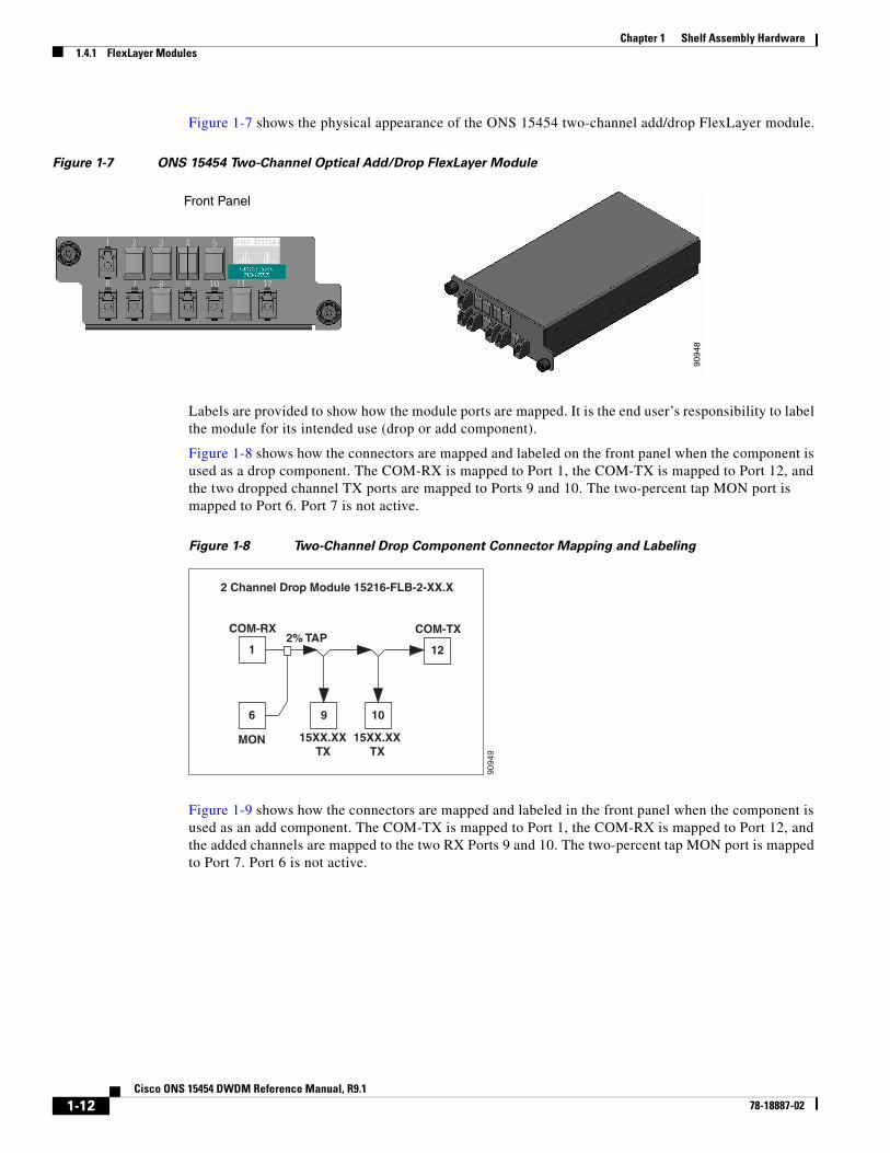
Figure 1-7 shows the physical appearance of the ONS 15454 two-channel add/drop FlexLayer module.
Figure 1-7 ONS 15454 Two-Channel Optical Add/Drop FlexLayer Module
Labels are provided to show how the module ports are mapped. It is the end user’s responsibility to label the module for its intended use (drop or add component).
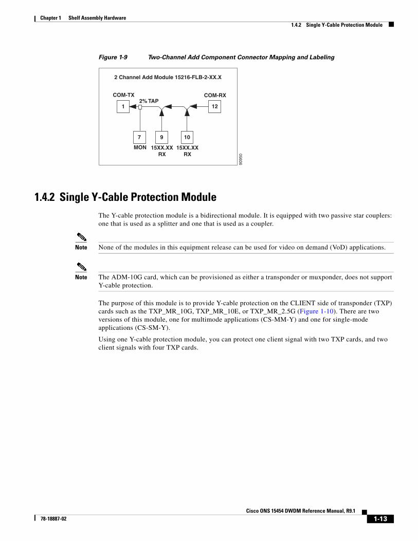
Figure 1-8 shows how the connectors are mapped and labeled on the front panel when the component is used as a drop component. The COM-RX is mapped to Port 1, the COM-TX is mapped to Port 12, and the two dropped channel TX ports are mapped to Ports 9 and 10. The two-percent tap MON port is mapped to Port 6. Port 7 is not active.
Figure 1-8 Two-Channel Drop Component Connector Mapping and Labeling
Figure 1-9 shows how the connectors are mapped and labeled in the front panel when the component is used as an add component. The COM-TX is mapped to Port 1, the COM-RX is mapped to Port 12, and the added channels are mapped to the two RX Ports 9 and 10. The two-percent tap MON port is mapped to Port 7. Port 6 is not active.
Front Panel
9094
8
1
6 9 10
2 Channel Drop Module 15216-FLB-2-XX.X
MON 15XX.XXTX
15XX.XXTX
COM-RX2% TAP
12
COM-TX
9094
9
1-12Cisco ONS 15454 DWDM Reference Manual, R9.1
78-18887-02
Chapter 1 Shelf Assembly Hardware1.4.2 Single Y-Cable Protection Module
Figure 1-9 Two-Channel Add Component Connector Mapping and Labeling
1.4.2 Single Y-Cable Protection ModuleThe Y-cable protection module is a bidirectional module. It is equipped with two passive star couplers: one that is used as a splitter and one that is used as a coupler.
Note None of the modules in this equipment release can be used for video on demand (VoD) applications.
Note The ADM-10G card, which can be provisioned as either a transponder or muxponder, does not support Y-cable protection.
The purpose of this module is to provide Y-cable protection on the CLIENT side of transponder (TXP) cards such as the TXP_MR_10G, TXP_MR_10E, or TXP_MR_2.5G (Figure 1-10). There are two versions of this module, one for multimode applications (CS-MM-Y) and one for single-mode applications (CS-SM-Y).
Using one Y-cable protection module, you can protect one client signal with two TXP cards, and two client signals with four TXP cards.
1
7 9 10
2 Channel Add Module 15216-FLB-2-XX.X
MON 15XX.XXRX
15XX.XXRX
COM-TX2% TAP
12
COM-RX
9095
0
1-13Cisco ONS 15454 DWDM Reference Manual, R9.1
78-18887-02
Chapter 1 Shelf Assembly Hardware1.4.2 Single Y-Cable Protection Module
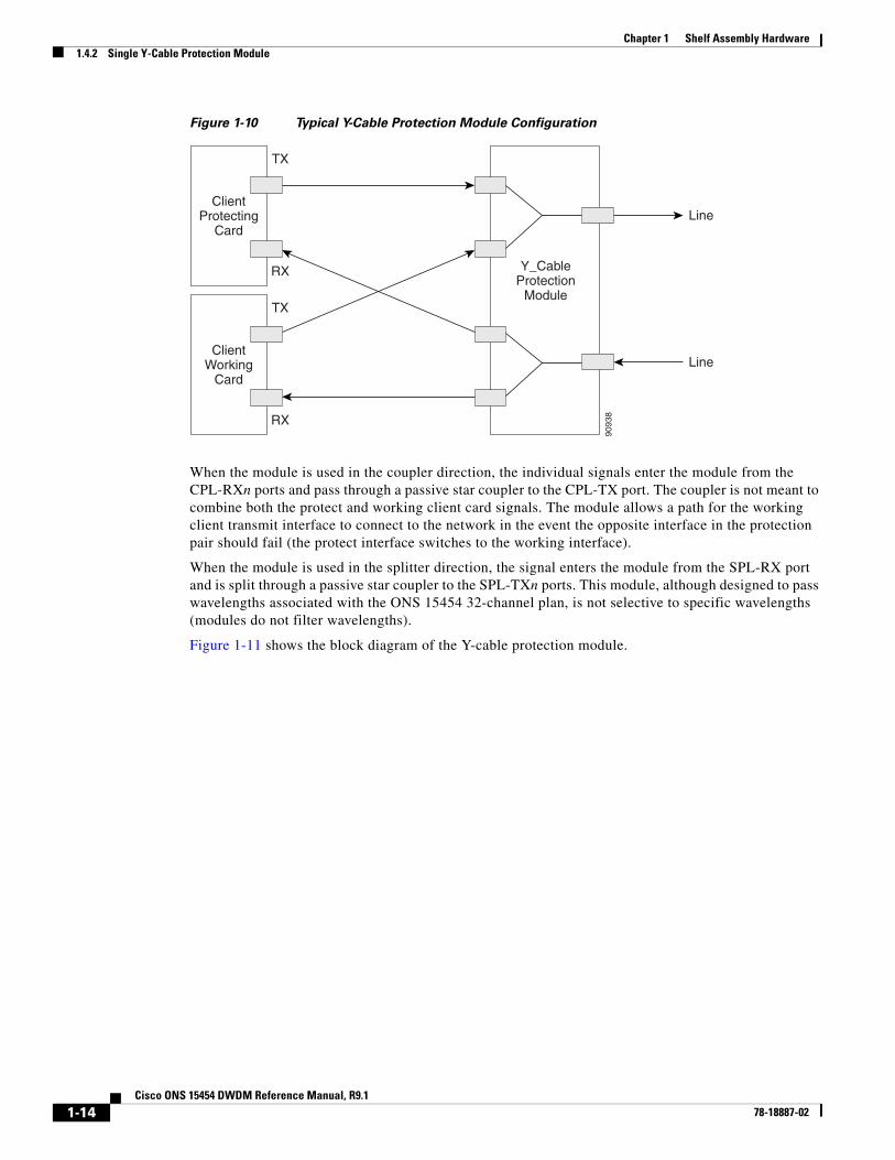
When the module is used in the coupler direction, the individual signals enter the module from the CPL-RXn ports and pass through a passive star coupler to the CPL-TX port. The coupler is not meant to combine both the protect and working client card signals. The module allows a path for the working client transmit interface to connect to the network in the event the opposite interface in the protection pair should fail (the protect interface switches to the working interface).
When the module is used in the splitter direction, the signal enters the module from the SPL-RX port and is split through a passive star coupler to the SPL-TXn ports. This module, although designed to pass wavelengths associated with the ONS 15454 32-channel plan, is not selective to specific wavelengths (modules do not filter wavelengths).
Figure 1-11 shows the block diagram of the Y-cable protection module.
9093
8
ClientProtecting
Card
TX
RX Y_CableProtection
Module
Line
LineClient
WorkingCard
TX
RX
1-14Cisco ONS 15454 DWDM Reference Manual, R9.1
78-18887-02
Chapter 1 Shelf Assembly Hardware1.4.2 Single Y-Cable Protection Module
Figure 1-12 and Figure 1-13 show the physical appearance of the ONS 15454 Y-Cable Protection FlexLayer Module. This module has two versions, one for single-mode applications and the other for multimode applications.
Figure 1-12 ONS 15454 Y-Cable Protection FlexLayer Module (Single-Mode)
SPLb-TX1
SPLb-TX2
SPLa-TX1
SPLa-TX2
CPLa-RX1
CPLa-RX2
CPLb-RX1
CPLb-RX2
CPLb-TX
SPLb-RX
CPLa-TX
SPLa-RX
9093
9
Front Panel
CS-SM-Y
9095
2
1-15Cisco ONS 15454 DWDM Reference Manual, R9.1
78-18887-02
Chapter 1 Shelf Assembly Hardware1.4.2 Single Y-Cable Protection Module
Figure 1-13 ONS 15454 Y-Cable Protection FlexLayer Module (Multimode)
Figure 1-14 shows how the module front panel ports are mapped and labeled. The multimode module is mapped and labeled the same as the single-mode module.
Figure 1-14 Y-Cable Protection Component Connector Mapping and Labeling
Table 1-2 details the single-mode and multimode front panel Protection A mapping. It shows how two DWDM receive inputs (client working and protect) provide one output signal to the customer client equipment, using the module combiner function.
Table 1-3 details the single-mode and multimode front panel Protection A mapping. It shows how the module splits a single receive input from the equipment into two DWDM output signals (working and protect) to the TXP client port.
Front Panel
CS-MM-Y
9094
0
1:2 Splitter and 2:1 Combiner 15216-CS-MM/SM-Y
7 8
TXa2 RXb2
9
TXb2
12
RXb
2 3 4
TXa1 RXb1 TXb1
6
RXa2
1
RXa1
10
RXa
5
TXa
11
TXb
9094
1
Table 1-2 Protection A (TXP Cards 1 and 2) Port Mapping: Combiner from DWDM
Receive Port on the Y-Cable Module Signal Sources
1 (RXa1) Client TX port on the TXP 1 card
6 (RXa2) Client TX port on the TXP 2 card
Transmit Port on the Y-Cable Module Signal Destination
5 (TXa) RX port on customer client equipment A
1-16Cisco ONS 15454 DWDM Reference Manual, R9.1
78-18887-02
Chapter 1 Shelf Assembly Hardware1.4.2 Single Y-Cable Protection Module
Table 1-4 details the single-mode and multimode front panel Protection B mapping. It shows how two DWDM receive inputs (client working and protect) provide one output signal to the equipment, using the module combiner function.
Table 1-5 details the single-mode and multimode front panel Protection B mapping. It shows how the module splits a single receive input from the equipment into two DWDM output signals (working and protect) to the client.
The following muxponder (MXP) and transponder (TXP) cards can use Y-cable protection:
• MXP_2.5_10G
• MXP_2.5_10E
• MXP_MR_2.5G
• TXP_MR_10G
• TXP_MR_10E
• TXP_MR_2.5G
• MXP_MR_10DME_C
• MXP_MR_10DME_L
Table 1-3 Protection A (TXP Cards 1 and 2) Port Mapping: Splitter to DWDM
Receive Port Signal Source
10 (RXa) TX port on customer client equipment A
Transmit Port Signal Destinations
2 (TXa1) Client RX port on the TXP 1 card
7 (TXa2) Client RX on the TXP 2 card
Table 1-4 Protection B (TXP Cards 3 and 4) Port Mapping: Combiner from DWDM
Receive Port Signal Sources
3 (RXb1) Client TX port on the TXP 3 card
8 (RXb2) Client TX port on the TXP 4 card
Transmit Port Signal Destination
11 (TXb) RX port on customer client equipment B
Table 1-5 Protection B (TXP Cards 3 and 4) Port Mapping: Splitter to DWDM
Note The MXP_MR_10DME_C card is labeled 10DME-C on the card faceplate. The MXP_MR_10DME_L card is labeled 10DME-L on the card faceplate.
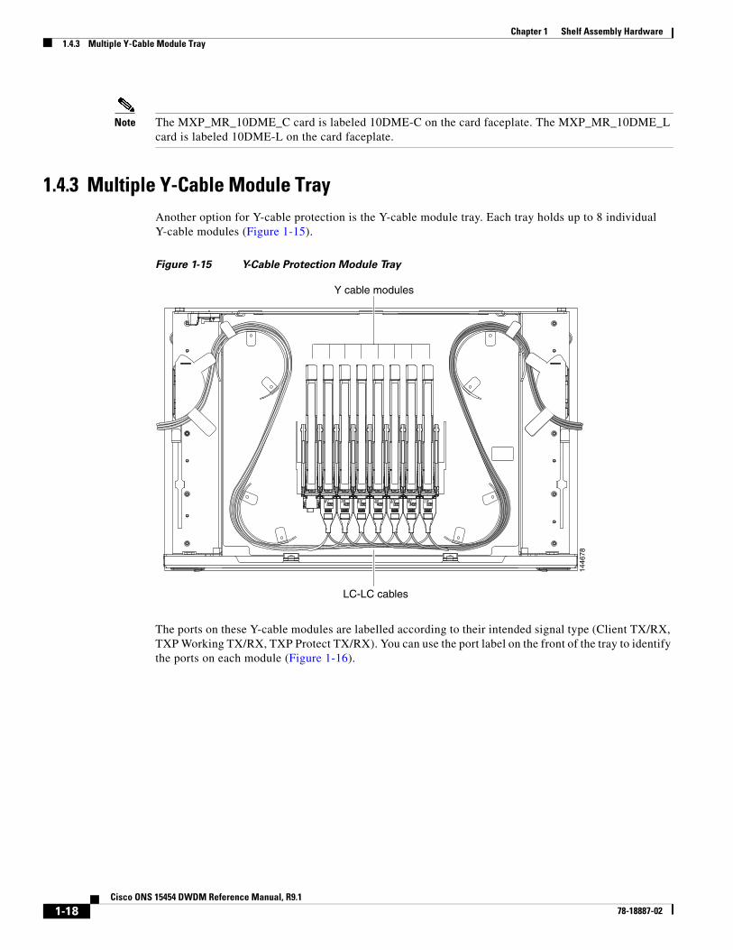
1.4.3 Multiple Y-Cable Module TrayAnother option for Y-cable protection is the Y-cable module tray. Each tray holds up to 8 individual Y-cable modules (Figure 1-15).
Figure 1-15 Y-Cable Protection Module Tray
The ports on these Y-cable modules are labelled according to their intended signal type (Client TX/RX, TXP Working TX/RX, TXP Protect TX/RX). You can use the port label on the front of the tray to identify the ports on each module (Figure 1-16).
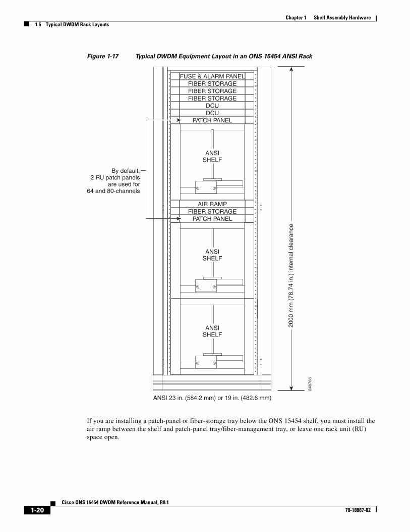
Figure 1-17 Typical DWDM Equipment Layout in an ONS 15454 ANSI Rack
If you are installing a patch-panel or fiber-storage tray below the ONS 15454 shelf, you must install the air ramp between the shelf and patch-panel tray/fiber-management tray, or leave one rack unit (RU) space open.
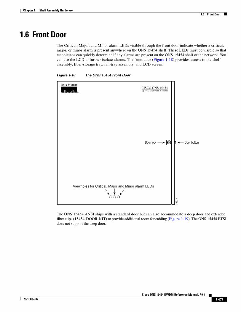
1.6 Front Door The Critical, Major, and Minor alarm LEDs visible through the front door indicate whether a critical, major, or minor alarm is present anywhere on the ONS 15454 shelf. These LEDs must be visible so that technicians can quickly determine if any alarms are present on the ONS 15454 shelf or the network. You can use the LCD to further isolate alarms. The front door (Figure 1-18) provides access to the shelf assembly, fiber-storage tray, fan-tray assembly, and LCD screen.
Figure 1-18 The ONS 15454 Front Door
The ONS 15454 ANSI ships with a standard door but can also accommodate a deep door and extended fiber clips (15454-DOOR-KIT) to provide additional room for cabling (Figure 1-19). The ONS 15454 ETSI does not support the deep door.
Door lock Door button
Viewholes for Critical, Major and Minor alarm LEDs
3392
3
CISCO ONS 15454Opt ica l Ne twork Sys t em
1-21Cisco ONS 15454 DWDM Reference Manual, R9.1
78-18887-02
Chapter 1 Shelf Assembly Hardware1.6 Front Door
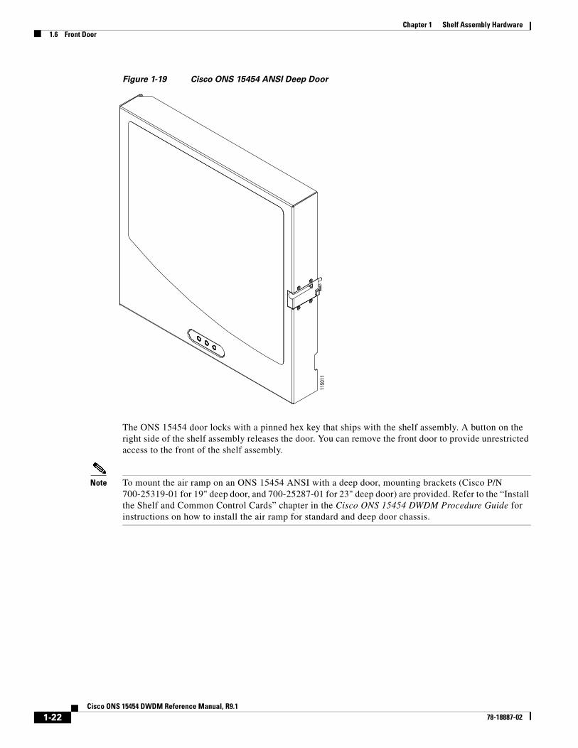
Figure 1-19 Cisco ONS 15454 ANSI Deep Door
The ONS 15454 door locks with a pinned hex key that ships with the shelf assembly. A button on the right side of the shelf assembly releases the door. You can remove the front door to provide unrestricted access to the front of the shelf assembly.
Note To mount the air ramp on an ONS 15454 ANSI with a deep door, mounting brackets (Cisco P/N 700-25319-01 for 19" deep door, and 700-25287-01 for 23" deep door) are provided. Refer to the “Install the Shelf and Common Control Cards” chapter in the Cisco ONS 15454 DWDM Procedure Guide for instructions on how to install the air ramp for standard and deep door chassis.
1150
11
1-22Cisco ONS 15454 DWDM Reference Manual, R9.1
78-18887-02
Chapter 1 Shelf Assembly Hardware1.6 Front Door
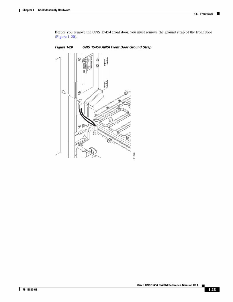
Before you remove the ONS 15454 front door, you must remove the ground strap of the front door (Figure 1-20).
Figure 1-20 ONS 15454 ANSI Front Door Ground Strap
7104
8
1-23Cisco ONS 15454 DWDM Reference Manual, R9.1
78-18887-02
Chapter 1 Shelf Assembly Hardware1.6 Front Door
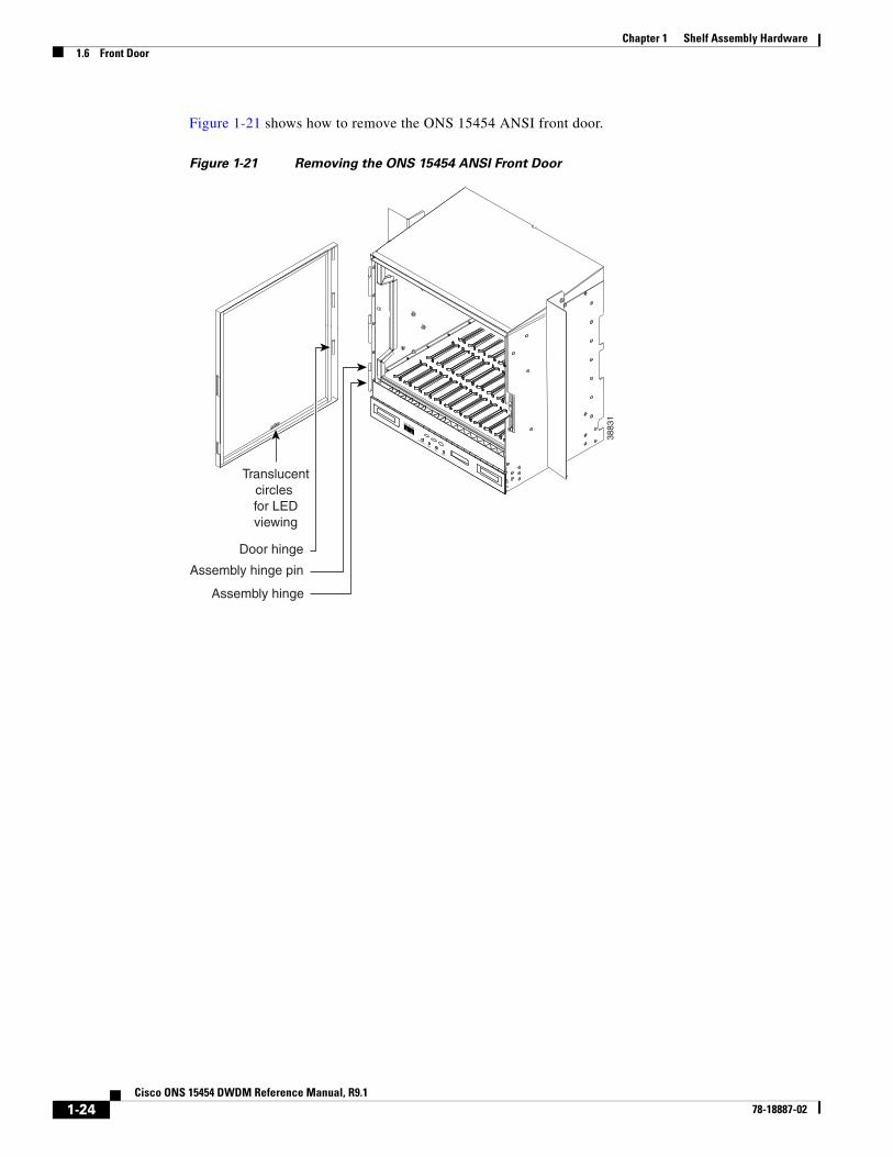
Figure 1-21 shows how to remove the ONS 15454 ANSI front door.
Figure 1-21 Removing the ONS 15454 ANSI Front Door
Door hinge
Assembly hinge pin
Assembly hinge
Translucentcircles for LEDviewing
3883
1
FAN FAILCRIT
MAJMIN
1-24Cisco ONS 15454 DWDM Reference Manual, R9.1
78-18887-02
Chapter 1 Shelf Assembly Hardware1.6 Front Door
Figure 1-22 shows how to remove the ONS 15454 ETSI front door.
Figure 1-22 Removing the ONS 15454 ETSI Front Door
An erasable label is pasted on the inside of the front door. You can use the label to record slot assignments, port assignments, card types, node ID, rack ID, and serial number for the ONS 15454.
6123
7
FAN FAILCRIT
MAJMIN
Door hinge
Assembly hinge pin
Assembly hinge
Translucentcircles for LEDviewing
1-25Cisco ONS 15454 DWDM Reference Manual, R9.1
78-18887-02
Chapter 1 Shelf Assembly Hardware1.6 Front Door
Figure 1-23 shows the erasable label on the ONS 15454 ANSI shelf.
Figure 1-23 ONS 15454 ANSI Front-Door Erasable Label
6184
0
1-26Cisco ONS 15454 DWDM Reference Manual, R9.1
78-18887-02
Chapter 1 Shelf Assembly Hardware1.6 Front Door
Figure 1-24 shows the erasable label on the ONS 15454 ETSI shelf.
Figure 1-24 ONS 15454 ETSI Front-Door Erasable Label
The front door label also includes the Class I and Class 1M laser warning. Figure 1-25 shows the ONS 15454 ANSI laser warning.
Figure 1-25 Laser Warning on the ONS 15454 ANSI Front-Door Label
Figure 1-26 shows the ONS 15454 ETSI laser warning.
P/N 47-12460-01 7809
8
6757
5
1-27Cisco ONS 15454 DWDM Reference Manual, R9.1
78-18887-02
Chapter 1 Shelf Assembly Hardware1.7 ONS 15454 ANSI Backplane Covers
Figure 1-26 Laser Warning on the ONS 15454 ETSI Front-Door Label
1.7 ONS 15454 ANSI Backplane CoversIf a backplane does not have an electrical interface assembly (EIA) panel installed, it should have two sheet metal backplane covers (one on each side of the backplane). See Figure 1-27. Each cover is held in place with nine 6-32 x 3/8 inch Phillips screws.
1.7.1 Lower Backplane CoverThe lower section of the ONS 15454 ANSI backplane is covered by either a clear plastic protector (15454-SA-ANSI) or a sheet metal cover (15454-SA-HD), which is held in place by five 6-32 x 1/2 inch screws. Remove the lower backplane cover to access the alarm interface panel (AIP), alarm pin fields, frame ground, and power terminals (Figure 1-28).
Figure 1-28 Removing the Lower Backplane Cover
B A
3207
4
Lower Backplane Cover
Backplane Sheet Metal Covers
3206
9
Retainingscrews
1-29Cisco ONS 15454 DWDM Reference Manual, R9.1
78-18887-02
Chapter 1 Shelf Assembly Hardware1.7.2 Rear Cover
1.7.2 Rear Cover The ONS 15454 ANSI has an optional clear plastic rear cover. This clear plastic cover provides additional protection for the cables and connectors on the backplane. Figure 1-29 shows the rear cover screw locations.
Figure 1-29 Backplane Attachment for Cover
You can also install the optional spacers if more space is needed between the cables and rear cover (Figure 1-30).
Figure 1-30 Installing the Plastic Rear Cover with Spacers
1.7.3 Alarm Interface PanelThe AIP is located above the alarm contacts on the lower section of the backplane. The AIP provides surge protection for the ONS 15454 ANSI. It also provides an interface from the backplane to the fan-tray assembly and LCD. The AIP plugs into the backplane using a 96-pin DIN connector and is held in place with two retaining screws. The panel has a nonvolatile memory chip that stores the unique node address (MAC address). The MAC address identifies the nodes that support circuits. It allows Cisco Transport Controller (CTC) to determine circuit sources, destinations, and spans. The TCC2/TCC2P cards in the ONS 15454 ANSI also use the MAC address to store the node database.
Note The 5-A AIP (73-7665-XX) is required when installing fan-tray assembly 15454-FTA3 or 15454-CC-FTA, which comes preinstalled on the shelf assembly (15454-SA-ANSI or 15454-SA-HD).
Note A blown fuse on the AIP board can cause the LCD display to go blank.
1.7.4 Alarm Interface Panel ReplacementIf the AIP fails, a MAC Fail alarm appears on the CTC Alarms menu and/or the LCD display on the fan-tray assembly goes blank. To perform an in-service replacement of the AIP, you must contact the Cisco Technical Assistance Center (Cisco TAC). For contact information, see the “Obtaining Documentation and Submitting a Service Request” section on page lxix.
5537
4
RET 1
CAUTION: R
emove power from both
the BAT1 and te
rminal b
locks
prior to
servicing
SUITABLE FOR MOUNTIN
G ON
A NON-C
OMBUSTIBLE S
URFACE.
PLEASE REFER TO IN
STALLATION
INSTRUCTIO
NS.
-42 TO -57 V
dc
650 Watts
Maxim
um
BAT 1RET 2
BAT 2
1-31Cisco ONS 15454 DWDM Reference Manual, R9.1
78-18887-02
Chapter 1 Shelf Assembly Hardware1.8 ONS 15454 ETSI Front Mount Electrical Connection
You can replace the AIP on an in-service system without affecting traffic (except Ethernet traffic on nodes running a release earlier than Software Release 4.0). The circuit repair feature allows you to repair circuits affected by MAC address changes on one node at a time. Circuit repair works when all nodes are running the same software version. Each individual AIP upgrade requires an individual circuit repair; if AIPs are replaced on two nodes, the circuit repair must be performed twice. Always replace an AIP during a maintenance window.
Caution Do not use a 2-A AIP with a 5-A fan-tray assembly; doing so causes a blown fuse on the AIP.
Note Ensure that all nodes in the affected network are running the same software version before replacing the AIP and repairing circuits. If you need to upgrade nodes to the same software version, no hardware should be changed or circuit repair performed until after the software upgrade is complete.
1.8 ONS 15454 ETSI Front Mount Electrical ConnectionThe ONS 15454 ETSI positive and negative power terminals are located on FMEC cards in the Electrical Facility Connection Assembly (EFCA). The ground connection is the grounding receptacle on the side panel of the shelf.
The ONS 15454 ETSI EFCA at the top of the shelf has 12 FMEC slots numbered sequentially from left to right (18 to 29). Slots 18 to 22 and 25 to 29 provide electrical connections. Slots 23 and 24 host the MIC-A/P and MIC-C/T/P cards, respectively. The MIC-A/P and the MIC-C/T/P cards also connect alarm, timing, LAN, and craft connections to the ONS 15454 ETSI.
For more information about the MIC-A/P and MIC-C/T/P cards, see Chapter 2, “Common Control Cards.”
1.9 ONS 15454 ANSI Alarm Expansion PanelThe optional ONS 15454 ANSI alarm expansion panel (AEP) can be used with the AIC-I card to provide an additional 48 dry alarm contacts for the ONS 15454 ANSI: 32 inputs and 16 outputs. The AEP is a printed circuit board assembly that is installed on the backplane. Figure 1-31 shows the AEP board; the left connector is the input connector and the right connector is the output connector.
The AIC-I without an AEP already contains direct alarm contacts. These direct AIC-I alarm contacts are routed through the backplane to wire-wrap pins accessible from the back of the shelf. If you install an AEP, you cannot use the alarm contacts on the wire-wrap pins. For more information about the AIC-I, see Chapter 2, “Common Control Cards.”
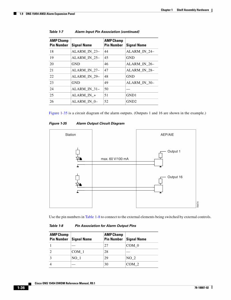
Each AEP alarm input port has a provisionable label and severity. The alarm inputs have optocoupler isolation. They have one common 32-VDC output and a maximum of 2 mA per input. Each opto-metal oxide semiconductor (MOS) alarm output can operate by definable alarm condition, a maximum open circuit voltage of 60 VDC, and a maximum current of 100 mA. See the “18.6 External Alarms and Controls” section on page 18-12 for further information.
Figure 1-33 shows the wire-wrapping connections on the shelf backplane used to connect to the AEP.
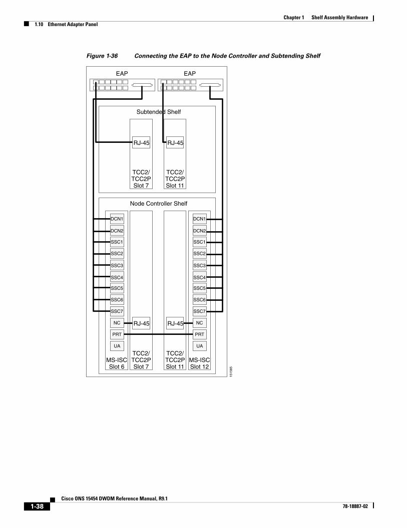
1.10 Ethernet Adapter PanelAn ethernet adapter panel (EAP) is required in an ANSI or ETSI equipment rack for multishelf configurations. Two EAPs are required in a multishelf configuration, one for each MS-ISC-100T card. Figure 1-36 shows an example of two installed EAPs and the connection between each EAP and a node controller shelf and a subtending shelf.
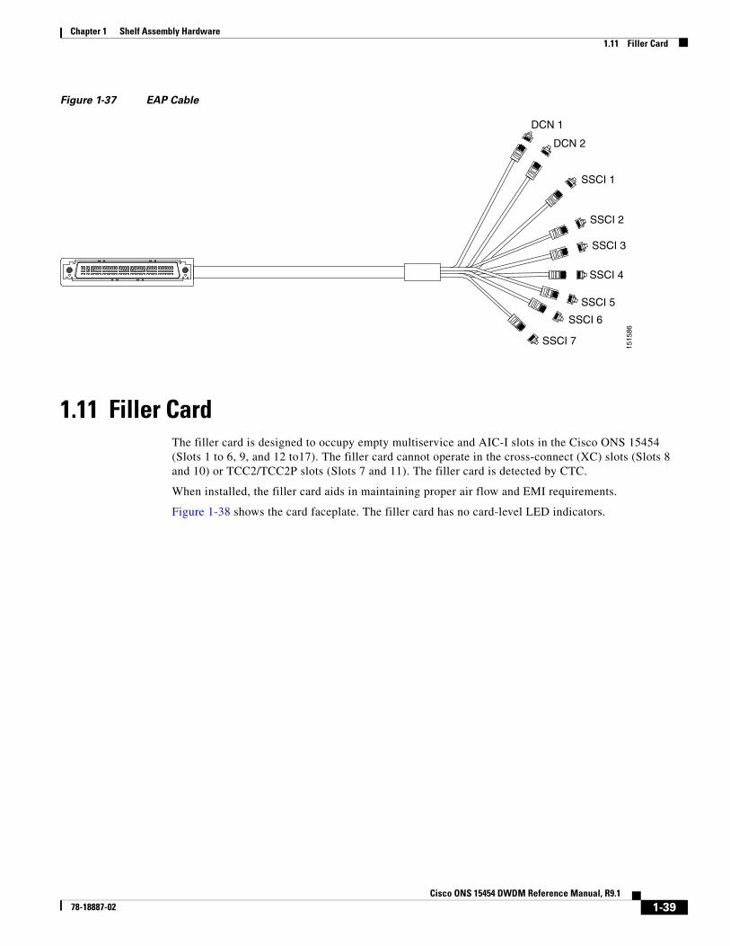
An EAP cable is used to connect the MS-ISC-100T card ports to the EAP (Figure 1-37). The nine connector ends plug into Ports 0 through 8 of the MS-ISC-100T card, and the multiport connector plugs into the EAP. Ports 0 and 1 on the MS-ISC-100T card are the DCN ports; Ports 2 through 7 are the SSC ports. A cross-over (CAT-5) LAN cable is used to connect the DCN port on the EAP to the front panel of the TCC2/TCC2P cards in the subtending shelves.
5 COM_3 31 —
6 NO_3 32 NO_4
7 — 33 COM_4
8 COM_5 34 —
9 NO_5 35 NO_6
10 — 36 COM_6
11 COM_7 37 —
12 NO_7 38 NO_8
13 — 39 COM_8
14 COM_9 40 —
15 NO_9 41 NO_10
16 — 42 COM_10
17 COM_11 43 —
18 NO_11 44 NO_12
19 — 45 COM_12
20 COM_13 46 —
21 NO_13 47 NO_14
22 — 48 COM_14
23 COM_15 49 —
24 NO_15 50 —
25 — 51 GND1
26 NO_0 52 GND2
Table 1-8 Pin Association for Alarm Output Pins (continued)
Figure 1-36 Connecting the EAP to the Node Controller and Subtending Shelf
EAP
Subtended Shelf
EAP
TCC2/TCC2PSlot 7
TCC2/TCC2PSlot 11
Node Controller Shelf
TCC2/TCC2PSlot 7
MS-ISCSlot 6
TCC2/TCC2PSlot 11
MS-ISCSlot 12
1515
85
RJ-45 RJ-45
RJ-45 RJ-45
PRT
NC
DCN1
DCN2
SSC1
SSC2
SSC3
SSC4
SSC5
SSC6
SSC7
PRT
UA UA
NC
DCN1
DCN2
SSC1
SSC2
SSC3
SSC4
SSC5
SSC6
SSC7
1-38Cisco ONS 15454 DWDM Reference Manual, R9.1
78-18887-02
Chapter 1 Shelf Assembly Hardware1.11 Filler Card
Figure 1-37 EAP Cable
1.11 Filler CardThe filler card is designed to occupy empty multiservice and AIC-I slots in the Cisco ONS 15454 (Slots 1 to 6, 9, and 12 to17). The filler card cannot operate in the cross-connect (XC) slots (Slots 8 and 10) or TCC2/TCC2P slots (Slots 7 and 11). The filler card is detected by CTC.
When installed, the filler card aids in maintaining proper air flow and EMI requirements.
Figure 1-38 shows the card faceplate. The filler card has no card-level LED indicators.
DCN 1
DCN 2
SSCI 1
SSCI 2
SSCI 3
SSCI 4
SSCI 5
SSCI 6
SSCI 7
1515
86
1-39Cisco ONS 15454 DWDM Reference Manual, R9.1
78-18887-02
Chapter 1 Shelf Assembly Hardware1.12 Cable Routing and Management
Figure 1-38 Filler Card Faceplate
1.12 Cable Routing and ManagementThe ONS 15454 cable management facilities include the following:
• Fiber patch panels
• A cable-routing channel (behind the fold-down door) that runs the width of the shelf assembly (Figure 1-41 on page 1-42)
• Plastic horseshoe-shaped fiber guides at each side opening of the cable-routing channel that ensure that the proper bend radius is maintained in the fibers (Figure 1-42 on page 1-42)
1242
34
FILLER
1-40Cisco ONS 15454 DWDM Reference Manual, R9.1
78-18887-02
Chapter 1 Shelf Assembly Hardware1.12 Cable Routing and Management
Note You can remove the fiber guide, if necessary, to create a larger opening (if you need to route CAT-5 Ethernet cables out the side, for example). To remove the fiber guide, take out the three screws that anchor it to the side of the shelf assembly.
• Cable tie-wrap facilities on EIAs that secure cables to the cover panel (ANSI only)
• Reversible jumper routing fins that enable you to route cables out either side by positioning the fins as desired
• Jumper slack storage reels (2) on each side panel that reduce the amount of slack in cables that are connected to other devices
Note To remove the jumper slack storage reels, take out the screw in the center of each reel.
• Optional fiber-storage tray (recommended for DWDM nodes)
• Optional tie-down bar (ANSI only)
Optical fibers without exposed metallic ferrule must be used with all the products and platforms covered by this document (see Figure 1-39 and Figure 1-40). Electrostatic discharge is more easily coupled into the equipment through exposed metallic ferrules near the fiber connectors.
Figure 1-39 Optical Fiber With Exposed Ferrule
Figure 1-40 Optical Fiber Without Exposed Ferrule
Figure 1-41 shows the cable management facilities that you can access through the fold-down front door, including the cable-routing channel and the jumper routing fins.
1.12.1 Fiber ManagementThe jumper routing fins are designed to route fiber jumpers out of both sides of the shelf. Slots 1 to 6 exit to the left, and Slots 12 to 17 exit to the right. Figure 1-42 shows fibers routed from cards in the left slots, down through the fins, then exiting out the fiber channel to the left. The maximum capacity of the fiber routing channel depends on the size of the fiber jumpers.
Figure 1-42 Fiber Capacity
Table 1-9 provides the maximum capacity of the fiber channel for one side of an ANSI shelf, depending on fiber size and number of Ethernet cables running through that fiber channel.
FAN FAILCRIT
MAJMIN
3423
8
Reversible jumperrouting fins
Fold downfront door
Fiber guides
9651
8
1-42Cisco ONS 15454 DWDM Reference Manual, R9.1
78-18887-02
Chapter 1 Shelf Assembly Hardware1.12.2 Fiber Management Using the Patch-Panel Trays
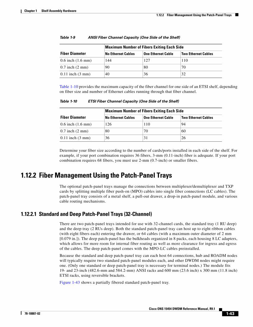
Table 1-10 provides the maximum capacity of the fiber channel for one side of an ETSI shelf, depending on fiber size and number of Ethernet cables running through that fiber channel.
Determine your fiber size according to the number of cards/ports installed in each side of the shelf. For example, if your port combination requires 36 fibers, 3-mm (0.11-inch) fiber is adequate. If your port combination requires 68 fibers, you must use 2-mm (0.7-inch) or smaller fibers.
1.12.2 Fiber Management Using the Patch-Panel TraysThe optional patch-panel trays manage the connections between multiplexer/demultiplexer and TXP cards by splitting multiple fiber push-on (MPO) cables into single fiber connections (LC cables). The patch-panel tray consists of a metal shelf, a pull-out drawer, a drop-in patch-panel module, and various cable routing mechanisms.
1.12.2.1 Standard and Deep Patch-Panel Trays (32-Channel)
There are two patch-panel trays intended for use with 32-channel cards, the standard tray (1 RU deep) and the deep tray (2 RUs deep). Both the standard patch-panel tray can host up to eight ribbon cables (with eight fibers each) entering the drawer, or 64 cables (with a maximum outer diameter of 2 mm [0.079 in.]). The deep patch-panel has the bulkheads organized in 8 packs, each housing 8 LC adapters, which allows for more room for internal fiber routing as well as more clearance for ingress and egress of the cables. The deep patch-panel comes with the MPO-LC cables preinstalled.
Because the standard and deep patch-panel tray can each host 64 connections, hub and ROADM nodes will typically require two standard patch-panel modules each, and other DWDM nodes might require one. (Only one standard or deep patch-panel tray is necessary for terminal nodes.) The module fits 19- and 23-inch (482.6-mm and 584.2-mm) ANSI racks and 600 mm (23.6 inch) x 300 mm (11.8 inch) ETSI racks, using reversible brackets.
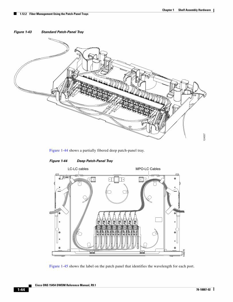
Figure 1-43 shows a partially fibered standard patch-panel tray.
Table 1-9 ANSI Fiber Channel Capacity (One Side of the Shelf)
Fiber Diameter
Maximum Number of Fibers Exiting Each Side
No Ethernet Cables One Ethernet Cable Two Ethernet Cables
0.6 inch (1.6 mm) 144 127 110
0.7 inch (2 mm) 90 80 70
0.11 inch (3 mm) 40 36 32
Table 1-10 ETSI Fiber Channel Capacity (One Side of the Shelf)
Fiber Diameter
Maximum Number of Fibers Exiting Each Side
No Ethernet Cables One Ethernet Cable Two Ethernet Cables
0.6 inch (1.6 mm) 126 110 94
0.7 inch (2 mm) 80 70 60
0.11 inch (3 mm) 36 31 26
1-43Cisco ONS 15454 DWDM Reference Manual, R9.1
78-18887-02
Chapter 1 Shelf Assembly Hardware1.12.2 Fiber Management Using the Patch-Panel Trays
Figure 1-43 Standard Patch-Panel Tray
Figure 1-44 shows a partially fibered deep patch-panel tray.
Figure 1-44 Deep Patch-Panel Tray
Figure 1-45 shows the label on the patch panel that identifies the wavelength for each port.
1240
07
1446
79
LC-LC cables MPO-LC Cables
1-44Cisco ONS 15454 DWDM Reference Manual, R9.1
78-18887-02
Chapter 1 Shelf Assembly Hardware1.12.2 Fiber Management Using the Patch-Panel Trays
Figure 1-45 Patch-Panel Port Wavelengths
1.12.2.2 40-Channel Patch-Panel Tray
The 40-channel patch panel tray is 2 RUs deep and comes preinstalled with MPO-LC cables. The 40-channel patch-panel tray can host up to 10 ribbon cables (with eight fibers each), for a total of 80 connections, and is used with expanded ROADM, terminal, hub, and mesh nodes. Expanded hub and ROADM nodes will typically require two 40-channel patch-panel modules each; terminal nodes require one 40-channel patch-panel tray; and one 40-channel patch-panel tray is needed for mesh nodes for each direction.
The module fits 19- and 23-inch (482.6-mm and 584.2-mm) ANSI racks and 600 mm (23.6 inch) x 300 mm (11.8 inch) ETSI racks, using reversible brackets.
Figure 1-46 shows a 40-channel patch-panel tray.
RXTX
RXTX
RXTX
RXTX
1532
.6nm
1536
.6nm
1531
.8nm
1531
.1nm
1530
.3nm
1535
.8nm
1535
.0nm
1534
.2nm
RXTX
RXTX
RXTX
RXTX
1540
.5nm
1544
.5nm
1539
.7nm
1538
.9nm
1538
.1nm
1543
.7nm
1542
.9nm
1542
.1nm
RXTX
RXTX
RXTX
RXTX
RXTX
RXTX
RXTX
RXTX
1548
.5nm
1552
.5nm
1547
.7nm
1546
.9nm
1546
.1nm
1551
.7nm
1550
.9nm
1550
.1nm
RXTX
RXTX
RXTX
RXTX
RXTX
RXTX
RXTX
RXTX
1556
.5nm
1560
.6nm
1555
.7nm
1554
.9nm
1554
.1nm
1559
.7nm
1558
.9nm
1558
.1nm
RXTX
RXTX
RXTX
RXTX
RXTX
RXTX
RXTX
RXTX
1446
761 32 54 76 8
1-45Cisco ONS 15454 DWDM Reference Manual, R9.1
78-18887-02
Chapter 1 Shelf Assembly Hardware1.12.2 Fiber Management Using the Patch-Panel Trays
Figure 1-46 40-Channel Patch-Panel Tray, Side View
Figure 1-47 shows the 40-channel patch-panel ports and corresponding wavelengths.
Figure 1-47 40-Channel (15454-PP-80) Patch-Panel Port Wavelengths
1.12.2.3 Mesh Patch-Panel Tray
There are two mesh patch-panel trays, four-degree (PP-MESH-4) and eight-degree (PP-MESH-8), which are intended for use with mesh nodes. Both trays are 2 RUs deep. The four-degree patch panel allows up to 4 sides to be used per mesh node, while the eight-degree patch panel allows up to 8 sides to be used per mesh node. The 4-degree patch-panel tray can host up to 4 MPO-MPO and 4 LC-LC cables, and the 8-degree patch-panel tray can host up to 8 MPO-MPO and 8 LC-LC cables. The module fits 19- and 23-inch (482.6-mm and 584.2-mm) ANSI racks and 600 mm (23.6 inch) x 300 mm (11.8 inch) ETSI racks, using reversible brackets.
1598
17
1597
12
TX
TX
TX
TX
TX
TX
TX
TX
TX
TX
RX
RX
RX
RX
RX
RX
RX
RX
RX
RX
TX
TX
TX
TX
TX
TX
TX
TX
TX
TX
RX
RX
RX
RX
RX
RX
RX
RX
RX
RX
TX
TX
TX
TX
TX
TX
TX
TX
TX
TX
RX
RX
RX
RX
RX
RX
RX
RX
RX
RX
TX
TX
TX
TX
TX
TX
TX
TX
TX
TX
RX
RX
RX
RX
RX
RX
RX
RX
RX
RX
1557
.3nm
1560
.6nm
1558
.1nm
1561
.4nm
1555
.7nm
1558
.9nm
1556
.5nm
1559
.7nm
1546
.1nm
1546
.9nm
1547
.7nm
1548
.5nm
1542
.9nm
1543
.7nm
1544
.5nm
1545
.3nm
1539
.7nm
1540
.5nm
1541
.3nm
1542
.1nm
1536
.6nm
1537
.4nm
1538
.1nm
1538
.9nm
1533
.4nm
1534
.2nm
1535
.0nm
1535
.8nm
1530
.3nm
1531
.1nm
1531
.8nm
1532
.6nm
1549
.3nm
1550
.1nm
1550
.9nm
1551
.7nm
1552
.5nm
1553
.3nm
1554
.1nm
1554
.9nm
1-46Cisco ONS 15454 DWDM Reference Manual, R9.1
78-18887-02
Chapter 1 Shelf Assembly Hardware1.12.3 Fiber Management Using the Y-Cable Module Tray
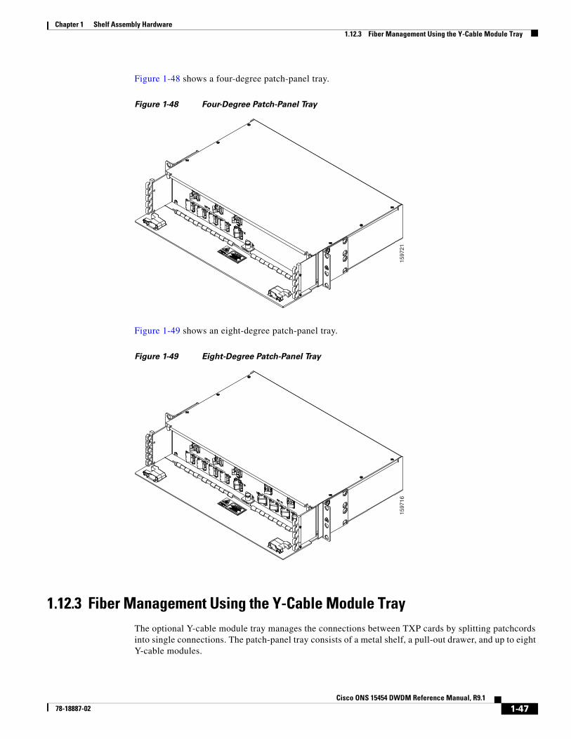
Figure 1-48 shows a four-degree patch-panel tray.
Figure 1-48 Four-Degree Patch-Panel Tray
Figure 1-49 shows an eight-degree patch-panel tray.
Figure 1-49 Eight-Degree Patch-Panel Tray
1.12.3 Fiber Management Using the Y-Cable Module TrayThe optional Y-cable module tray manages the connections between TXP cards by splitting patchcords into single connections. The patch-panel tray consists of a metal shelf, a pull-out drawer, and up to eight Y-cable modules.
1597
2115
9716
1-47Cisco ONS 15454 DWDM Reference Manual, R9.1
78-18887-02
Chapter 1 Shelf Assembly Hardware1.12.4 Fiber Management Using the Fiber-Storage Tray
Figure 1-50 shows a fibered Y-cable module tray.
Figure 1-50 Y-Cable Module Tray
To ensure diversity of the fiber coming from different cards in the Y-cable scheme, one pair of fibers (e.g. from the active transponder) should come out on the opposite side from the second pair of fibers (e.g. standby transponder), according to local site practice.
1.12.4 Fiber Management Using the Fiber-Storage TrayCisco recommends installing at least one fiber-storage tray in multinode racks to facilitate fiber-optic cable management for DWDM applications. This tray is usually used to store slack cable from cables installed between cards within a single node. Refer to Figure 1-17 on page 1-20 for typical mounting locations.
Table 1-11 provides the fiber capacity for each tray.
Figure 1-51 shows an example of a fiber-management tray with fiber-optic cables routed through it. You can route cables around the cable rounders, entering and exiting from either side, as necessary. Route fibers as necessary for your site configuration.
RXTX
RXTX
RXTX
RXTX
1532
.6nm
1536
.6nm
1531
.8nm
1531
.1nm
1530
.3nm
1535
.8nm
1535
.0nm
1534
.2nm
RXTX
RXTX
RXTX
RXTX
1540
.5nm
1544
.5nm
1539
.7nm
1538
.9nm
1538
.1nm
1543
.7nm
1542
.9nm
1542
.1nm
RXTX
RXTX
RXTX
RXTX
RXTX
RXTX
RXTX
RXTX
1548
.5nm
1552
.5nm
1547
.7nm
1546
.9nm
1546
.1nm
1551
.7nm
1550
.9nm
1550
.1nm
RXTX
RXTX
RXTX
RXTX
RXTX
RXTX
RXTX
RXTX
1556
.5nm
1560
.6nm
1555
.7nm
1554
.9nm
1554
.1nm
1559
.7nm
1558
.9nm
1558
.1nm
RXTX
RXTX
RXTX
RXTX
RXTX
RXTX
RXTX
RXTX
1446
761 32 54 76 8
Table 1-11 Fiber-Storage Tray Capacity
Fiber Diameter Maximum Number of Fibers Exiting Each Side
0.6 inch (1.6 mm) 62
0.7 inch (2 mm) 48
0.11 inch (3 mm) 32
1-48Cisco ONS 15454 DWDM Reference Manual, R9.1
78-18887-02
Chapter 1 Shelf Assembly Hardware1.12.5 Fiber Management Using the Optional ANSI Tie-Down Bar
Figure 1-51 Fiber-Storage Tray
1.12.5 Fiber Management Using the Optional ANSI Tie-Down BarYou can install a 5-inch (127-mm) tie-down bar on the rear of the ANSI chassis. You can use tie-wraps or other site-specific material to bundle the cabling and attach it to the bar so that you can more easily route the cable away from the rack.
Figure 1-52 shows the tie-down bar, the ONS 15454 ANSI, and the rack.
Figure 1-52 Tie-Down Bar on the Cisco ONS 15454 ANSI Shelf Assembly
1.13 Fan-Tray Assembly The fan-tray assembly is located at the bottom of the ONS 15454 shelf assembly. The fan tray is a removable drawer that holds fans and fan-control circuitry for the ONS 15454. The front door can be left in place or removed before installing the fan-tray assembly. After you install the fan tray, you should only need to access it if a fan failure occurs or if you need to replace or clean the fan-tray air filter. Refer to the “Maintain the Node” chapter in the Cisco ONS 15454 DWDM Procedure Guide to clean and replace the fan-tray assembly.
The front of the fan-tray assembly has an LCD screen that provides slot- and port-level information for all card slots, including the number of Critical, Major, and Minor alarms.
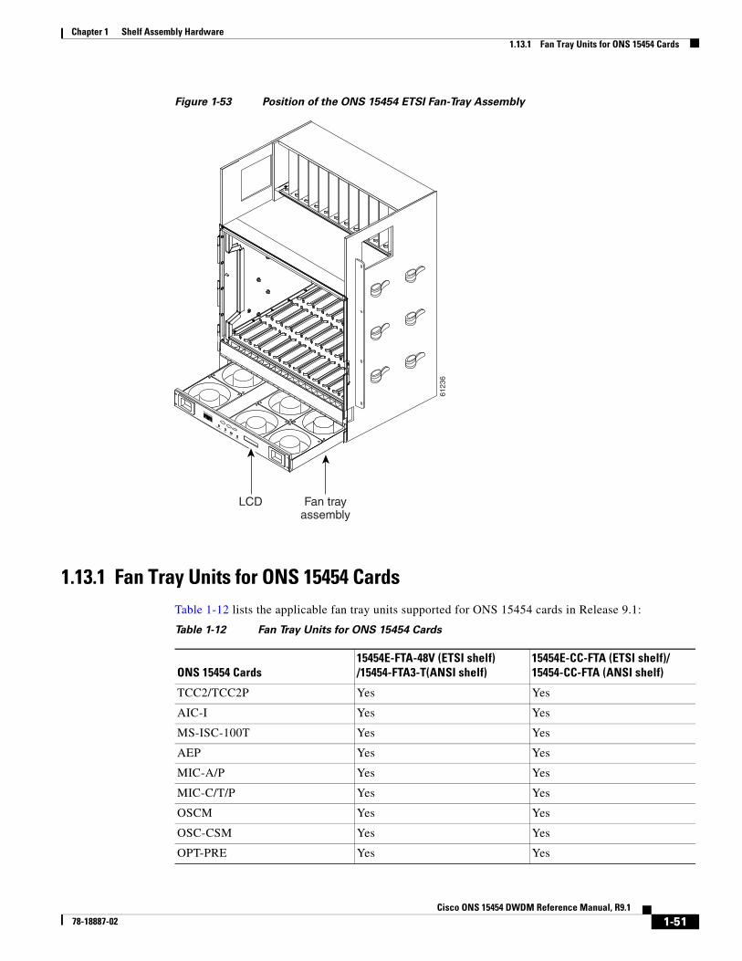
The fan-tray assembly features an air filter at the bottom of the tray that you can install and remove by hand. Remove and visually inspect this filter every 30 days and keep spare filters in stock. Refer to the “Maintain the Node” chapter in the Cisco ONS 15454 DWDM Procedure Guide for information about cleaning and maintaining the fan-tray air filter. Figure 1-53 shows the position of the ONS 15454 ETSI fan-tray assembly. (The fan-tray assembly on the ONS 15454 ANSI is located in a similar position.)
Caution Do not operate an ONS 15454 without the mandatory fan-tray air filter.
Caution Fan-tray assembly 15454E-CC-FTA (ETSI shelf)/15454-CC-FTA (ANSI shelf) is required when any of the following cards are used in an ONS 15454 DWDM application: ADM-10G, GE_XP, 10GE_XP, GE_XPE, 10GE_XPE, ML-MR-10, and CE-MR-10.
Caution The 15454-FTA3-T fan-tray assembly can only be installed in ONS 15454 Release 3.1 and later shelf assemblies (15454-SA-ANSI, P/N: 800-19857; 15454-SA-HD, P/N: 800-24848). The fan-tray assembly includes a pin that prevents it from being installed in ONS 15454 shelf assemblies released before ONS 15454 Release 3.1 (15454-SA-NEBS3E, 15454-SA-NEBS3, and 15454-SA-R1). Equipment damage can result from attempting to install the 15454-FTA3 in an incompatible shelf assembly.
Note 15454-CC-FTA is compatible with Software Release 2.2.2 and greater and shelf assemblies 15454-SA-HD and 15454-SA-ANSI. 15454E-CC-FTA is compatible with Software Release 4.0 and greater and shelf assembly 15454-SA-ETSI.
1-50Cisco ONS 15454 DWDM Reference Manual, R9.1
78-18887-02
Chapter 1 Shelf Assembly Hardware1.13.1 Fan Tray Units for ONS 15454 Cards
Figure 1-53 Position of the ONS 15454 ETSI Fan-Tray Assembly
1.13.1 Fan Tray Units for ONS 15454 CardsTable 1-12 lists the applicable fan tray units supported for ONS 15454 cards in Release 9.1:
6123
6
FAN FAILCRIT
MAJMIN
Fan trayassembly
LCD
Table 1-12 Fan Tray Units for ONS 15454 Cards
ONS 15454 Cards15454E-FTA-48V (ETSI shelf) /15454-FTA3-T(ANSI shelf)
1.13.2 Fan SpeedFan speed is controlled by the TCC2/TCC2P card’s temperature sensors. The sensors measure the input air temperature at the fan-tray assembly. Fan speed options are low, medium, and high. If the TCC2/TCC2P card fails, the fans automatically shift to high speed. The temperature measured by the TCC2/TCC2P sensors appears on the LCD screen.
1.13.3 Fan FailureIf one or more fans fail on the fan-tray assembly, replace the entire assembly. You cannot replace individual fans. The red Fan Fail LED on the front of the fan tray illuminates when one or more fans fail. The red Fan Fail LED clears after you install a working fan tray.
Caution As with the FTA3, the 15454E-CC-FTA (for ETSI) and 15454-CC-FTA (for ANSI) Fan Fail LED on the front of the fan-tray assembly illuminates when one or more fans fail to indicate that a fan-tray assembly or AIP replacement is required. But the Fan Fail LED on the 15454E-CC-FTA and 15454-CC-FTA will also illuminate when only one power source is connected to the chassis, and or any fuse blows. In such conditions, the Fan Alarm is triggered and the fans run at maximum speed.
TXP_MR_10E Yes Yes
MXP_2.5G_10E Yes Yes
MXP_MR_2.5G Yes Yes
MXPP_MR_2.5G Yes Yes
TXP_MR_10E_C Yes Yes
TXP_MR_10E_L Yes Yes
MXP_2.5G_10E_C Yes Yes
MXP_2.5G_10E_L Yes Yes
MXP_MR_10DME_C Yes Yes
MXP_MR_10DME_L Yes Yes
GE_XP/10GE_XP No Yes
ADM-10G No Yes
GE_XPE/10GE_XPE No Yes
OTU2_XP No Yes
MLSE UT Yes Yes
TXP_MR_10EX_C Yes Yes
MXP_2.5G_10EX_C Yes Yes
MXP_MR_10DMEX_C Yes Yes
Table 1-12 Fan Tray Units for ONS 15454 Cards
ONS 15454 Cards15454E-FTA-48V (ETSI shelf) /15454-FTA3-T(ANSI shelf)
Chapter 1 Shelf Assembly Hardware1.13.4 Air Filter
1.13.4 Air Filter The ONS 15454 contains a reusable air filter (for ANSI: 15454-FTF2; for ETSI: 15454E-ETSI-FTF) that is installed either below the fan-tray assembly or, for the ONS 15454 ANSI, in the optional external filter brackets.
The reusable filter is made of a gray, open-cell, polyurethane foam that is specially coated to provide fire and fungi resistance. All versions of the ONS 15454 can use the reusable air filter. Spare filters should be kept in stock. Inspect the air filter every 30 days, and clean the filter every three to six months. Replace the air filter every two to three years. Avoid cleaning the air filter with harsh cleaning agents or solvents.
Earlier versions of the ONS 15454 ANSI shelf used a disposable air filter that is installed beneath the fan-tray assembly only. However, the reusable air filter is backward compatible.
1.14 Power and Ground DescriptionGround the equipment according to Telcordia standards or local practices. The following sections describe power and ground for the ONS 15454 shelves.
Note For detailed instructions on grounding the ONS 15454 ANSI or ONS 15454 ETSI chassis, refer to the Cisco ONS Electrostatic Discharge (ESD) and Grounding Guide.
1.14.1 ONS 15454 ANSI Power and GroundCisco recommends the following wiring conventions, but customer conventions prevail:
• Red wire for battery connections (–48 VDC).
• Black wire for battery return connections (0 VDC).
• The battery return connection is treated as DC-I, as defined in Telcordia GR-1089-CORE, Issue 3.
The ONS 15454 ANSI has redundant –48 VDC #8 power terminals on the shelf-assembly backplane. The terminals are labeled BAT1, RET1, BAT2, and RET2 and are located on the lower section of the backplane behind a clear plastic cover.
To install redundant power feeds, use four power cables and one ground cable. For a single power feed, only two power cables (#10 AWG, copper conductor, 194 degrees F [90 degrees C]) and one ground cable (#6 AWG) are required. Use a conductor with low impedance to ensure circuit overcurrent protection. However, the conductor must have the capability to safely conduct any faulty current that might be imposed.
The existing ground post is a #10-32 bolt. The nut provided for a field connection is also a #10 AWG, with an integral lock washer. The lug must be a dual-hole type and rated to accept the #6 AWG cable. Two posts are provided on the ONS 15454 ANSI to accommodate the dual-hole lug. Figure 1-54 shows the location of the ground posts.
Chapter 1 Shelf Assembly Hardware1.14.2 ONS 15454 ETSI Power and Ground
Figure 1-54 Ground Posts on the ONS 15454 ANSI Backplane
1.14.2 ONS 15454 ETSI Power and GroundThe ONS 15454 ETSI has redundant –48 VDC power connectors on the MIC-A/P and MIC-C/T/P faceplates. To install redundant power feeds, use the two power cables shipped with the ONS 15454 ETSI and one ground cable. For details, see the “2.6.1 MIC-A/P FMEC” section on page 2-18 and the “2.6.2 MIC-C/T/P FMEC” section on page 2-21.
Caution Only use the power cables shipped with the ONS 15454 ETSI.
1.15 Shelf Voltage and Temperature
Note The temperature measured by the TCC2/TCC2P sensors appears on the LCD screen in the ONS 15454 chassis.
The input voltages and temperature of the ONS 15454 chassis are displayed in the Shelf view > Provisioning > General > Voltage/Temperature pane in CTC. The voltage supplied to the shelf (in millivolts) is displayed in the Voltage area of the Voltage/Temperature pane. The temperature of the shelf (in degree Celsius) is displayed in the Temperature area of the pane.
The Voltage/Temperature pane retrieves the following values for the ONS 15454 chassis:
• Voltage A—Voltage of the shelf that corresponds to power supply A, in millivolts.
• Voltage B—Voltage of the shelf that corresponds to power supply B, in millivolts.
• Chassis Temperature—Temperature of the shelf, in degrees Celsius.
In multishelf configuration, the voltage and temperature of each shelf is displayed in the Shelf view > Provisioning > General > Voltage/Temperature pane.
1.16 ONS 15454 ANSI Alarm, Timing, LAN, and Craft Pin Connections
Pin connections are provided on the ONS 15454 ANSI backplane. For information about ONS 15454 ETSI connections, see the “1.8 ONS 15454 ETSI Front Mount Electrical Connection” section on page 1-32.
FRAME GROUND 6185
2
Attach #6 AWG
1-55Cisco ONS 15454 DWDM Reference Manual, R9.1
78-18887-02
Chapter 1 Shelf Assembly Hardware1.16 ONS 15454 ANSI Alarm, Timing, LAN, and Craft Pin Connections
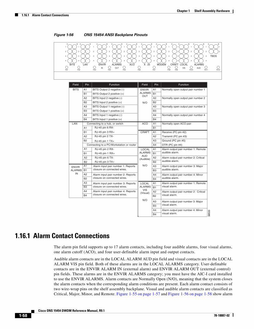
The ONS 15454 ANSI has a backplane pin field located at the bottom of the backplane. The backplane pin field provides 0.045 inch2 (29 mm2) wire-wrap pins for enabling external alarms, timing input and output, and craft interface terminals. This section describes the backplane pin field and the pin assignments for the field. Figure 1-56 on page 1-58 shows the wire-wrap pins on the backplane pin field. Beneath each wire-wrap pin is a frame ground pin. Frame ground pins are labeled FG1, FG2, FG3, etc. Install the ground shield of the cables connected to the backplane to the ground pin that corresponds to the pin field used.
Note The AIC-I requires a shelf assembly running Software R3.4.0 or later. The backplane of the ANSI shelf contains a wire-wrap field with pin assignment according to the layout in Figure 1-55 on page 1-57. The shelf assembly might be an existing shelf that has been upgraded to Software R3.4 or later. In this case, the backplane pin labeling appears as indicated in Figure 1-56 on page 1-58, but you must use the pin assignments provided by the AIC-I card as shown in Figure 1-55 on page 1-57.
1-56Cisco ONS 15454 DWDM Reference Manual, R9.1
78-18887-02
Chapter 1 Shelf Assembly Hardware1.16 ONS 15454 ANSI Alarm, Timing, LAN, and Craft Pin Connections
Figure 1-55 Cisco ONS 15454 Backplane Pinouts (Release 3.4 or Later)
1.16.1 Alarm Contact ConnectionsThe alarm pin field supports up to 17 alarm contacts, including four audible alarms, four visual alarms, one alarm cutoff (ACO), and four user-definable alarm input and output contacts.
Audible alarm contacts are in the LOCAL ALARM AUD pin field and visual contacts are in the LOCAL ALARM VIS pin field. Both of these alarms are in the LOCAL ALARMS category. User-definable contacts are in the ENVIR ALARM IN (external alarm) and ENVIR ALARM OUT (external control) pin fields. These alarms are in the ENVIR ALARMS category; you must have the AIC-I card installed to use the ENVIR ALARMS. Alarm contacts are Normally Open (N/O), meaning that the system closes the alarm contacts when the corresponding alarm conditions are present. Each alarm contact consists of two wire-wrap pins on the shelf assembly backplane. Visual and audible alarm contacts are classified as Critical, Major, Minor, and Remote. Figure 1-55 on page 1-57 and Figure 1-56 on page 1-58 show alarm
Field Pin Function Field Pin Function
BITS A1 BITS Output 2 negative (-) ENVIR ALARMS
OUT
N/O
A1 Normally open output pair number 1
B1 BITS Output 2 positive (+) B1
A2 BITS Input 2 negative (-) A2 Normally open output pair number 2
B2 BITS Input 2 positive (+) B2
A3 BITS Output 1 negative (-) A3 Normally open output pair number 3
B3 BITS Output 1 positive (+) B3
A4 BITS Input 1 negative (-) A4 Normally open output pair number 4
B4 BITS Input 1 positive (+) B4
LAN Connecting to a hub, or switch ACO A1 Normally open ACO pair
A1 B1
B1 CRAFT A1 Receive (PC pin #2)
A2 A2 Transmit (PC pin #3)
B2 A3 Ground (PC pin #5)
A4 DTR (PC pin #4)
LOCALALARMS
AUD(Audible)
N/O
N/O
A1 Alarm output pair number 1: Remote audible alarm.B1 B1
ENVIRALARMS
IN
A2 Alarm output pair number 2: Critical audible alarm.B2
A3 Alarm output pair number 3: Major audible alarm.
A1
B3B1
A4 Alarm output pair number 4: Minor audible alarm.
A2
B4B2
LOCALALARMS
VIS(Visual)
A1 Alarm output pair number 1: Remotevisual alarm.
A3
B1
A2 Alarm output pair number 2: Criticalvisual alarm.B2
A3 Alarm output pair number 3: Majorvisual alarm.B3
A4 Alarm output pair number 4: Minor visual alarm.B4
A1
A2
B3
A4
B4
RJ-45 pin 2 TX-
RJ-45 pin 1 TX+
RJ-45 pin 2 RX-
RJ-45 pin 1 RX+
RJ-45 pin 6 TX-
Alarm input pair number 1: Reports closure on connected wires.
Alarm input pair number 2: Reports closure on connected wires.
Alarm input pair number 3: Reports closure on connected wires.
Alarm input pair number 4: Reportsclosure on connected wires.
Connecting to a PC/Workstation or router
RJ-45 pin 3 TX+B2
RJ-45 pin 3 RX+
RJ-45 pin 6 RX-
TBOS
AUDVISFG12FG11FG10FG9FG8FG7FG6FG5FG4FG3FG2
BITS LAN
FG1
111111111111
2222222222
3333333333
4444444444
2
3
4
2
ABABAABABABABABABABA B
LOCAL ALARMSCRAFTMODEM X . 25 ACO ENVIR ALARMSOUTIN
Visual and audible alarms are typically wired to trigger an alarm light or bell at a central alarm collection point when the corresponding contacts are closed. You can use the ACO pins to activate a remote ACO for audible alarms. You can also activate the ACO function by pressing the ACO button on the TCC2/TCC2P card faceplate. The ACO function clears all audible alarm indications. After clearing the audible alarm indication, the alarm is still present and viewable in the Alarms tab in CTC.
1.16.2 Timing ConnectionsThe ONS 15454 ANSI backplane supports two building integrated timing supply (BITS) clock pin fields. The first four BITS pins, rows 3 and 4, support output and input from the first external timing device. The last four BITS pins, rows 1 and 2, perform the identical functions for the second external timing device. Table 1-13 lists the pin assignments for the BITS timing pin fields.
Note For timing connection, use 100-ohm shielded BITS clock cable pair #22 or #24 AWG (0.51 mm² [0.020 inch] or 0.64 mm² [0.0252 inch]), twisted-pair T1-type.
Note Refer to Telcordia SR-NWT-002224 for rules about provisioning timing references.
1.16.3 LAN ConnectionsUse the LAN pins on the ONS 15454 ANSI backplane to connect the ONS 15454 ANSI to a workstation or Ethernet LAN, or to a LAN modem for remote access to the node. You can also use the LAN port on the TCC2/TCC2P faceplate to connect a workstation or to connect the ONS 15454 ANSI to the network. Table 1-14 shows the LAN pin assignments.
Before you can connect an ONS 15454 ANSI to other ONS 15454 ANSI shelves or to a LAN, you must change the default IP address that is shipped with each ONS 15454 ANSI (192.1.0.2).
Table 1-13 BITS External Timing Pin Assignments
External Device Contact Tip and Ring Function
First external device A3 (BITS 1 Out) Primary ring (–) Output to external device
B3 (BITS 1 Out) Primary tip (+) Output to external device
A4 (BITS 1 In) Secondary ring (–) Input from external device
B4 (BITS 1 In) Secondary tip (+) Input from external device
Second external device A1 (BITS 2 Out) Primary ring (–) Output to external device
B1 (BITS 2 Out) Primary tip (+) Output to external device
A2 (BITS 2 In) Secondary ring (–) Input from external device
B2 (BITS 2 In) Secondary tip (+) Input from external device
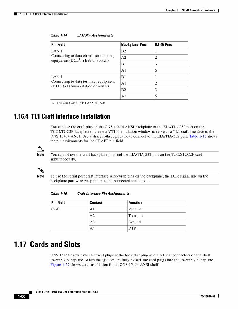
1.16.4 TL1 Craft Interface InstallationYou can use the craft pins on the ONS 15454 ANSI backplane or the EIA/TIA-232 port on the TCC2/TCC2P faceplate to create a VT100 emulation window to serve as a TL1 craft interface to the ONS 15454 ANSI. Use a straight-through cable to connect to the EIA/TIA-232 port. Table 1-15 shows the pin assignments for the CRAFT pin field.
Note You cannot use the craft backplane pins and the EIA/TIA-232 port on the TCC2/TCC2P card simultaneously.
Note To use the serial port craft interface wire-wrap pins on the backplane, the DTR signal line on the backplane port wire-wrap pin must be connected and active.
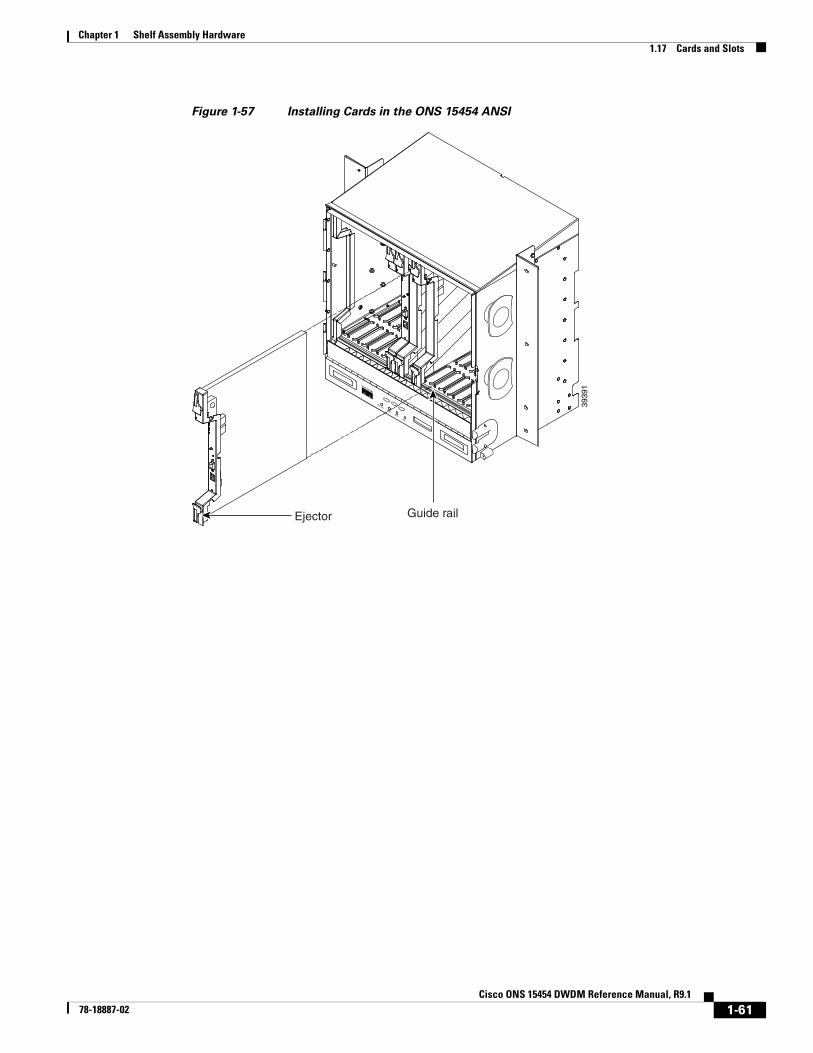
1.17 Cards and Slots ONS 15454 cards have electrical plugs at the back that plug into electrical connectors on the shelf assembly backplane. When the ejectors are fully closed, the card plugs into the assembly backplane. Figure 1-57 shows card installation for an ONS 15454 ANSI shelf.
Table 1-14 LAN Pin Assignments
Pin Field Backplane Pins RJ-45 Pins
LAN 1 Connecting to data circuit-terminating equipment (DCE1, a hub or switch)
1. The Cisco ONS 15454 ANSI is DCE.
B2 1
A2 2
B1 3
A1 6
LAN 1Connecting to data terminal equipment (DTE) (a PC/workstation or router)
B1 1
A1 2
B2 3
A2 6
Table 1-15 Craft Interface Pin Assignments
Pin Field Contact Function
Craft A1 Receive
A2 Transmit
A3 Ground
A4 DTR
1-60Cisco ONS 15454 DWDM Reference Manual, R9.1
78-18887-02
Chapter 1 Shelf Assembly Hardware1.17 Cards and Slots
Figure 1-57 Installing Cards in the ONS 15454 ANSI
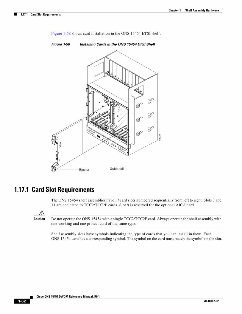
Figure 1-58 shows card installation in the ONS 15454 ETSI shelf.
Figure 1-58 Installing Cards in the ONS 15454 ETSI Shelf
1.17.1 Card Slot RequirementsThe ONS 15454 shelf assemblies have 17 card slots numbered sequentially from left to right. Slots 7 and 11 are dedicated to TCC2/TCC2P cards. Slot 9 is reserved for the optional AIC-I card.
Caution Do not operate the ONS 15454 with a single TCC2/TCC2P card. Always operate the shelf assembly with one working and one protect card of the same type.
Shelf assembly slots have symbols indicating the type of cards that you can install in them. Each ONS 15454 card has a corresponding symbol. The symbol on the card must match the symbol on the slot.
Table 1-16 shows the slot and card symbol definitions.
1.17.2 Card ReplacementTo replace an ONS 15454 card with another card of the same type, you do not need to make any changes to the database; remove the old card and replace it with a new card. To replace a card with a card of a different type, physically remove the card and replace it with the new card, then delete the original card from CTC. For specifics, refer to the “Maintain the Node” chapter in the Cisco ONS 15454 DWDM Procedure Guide.
Caution Removing any active card from the ONS 15454 can result in traffic interruption. Use caution when replacing cards and verify that only inactive or standby cards are being replaced. If the active card needs to be replaced, switch it to standby prior to removing the card from the node. For traffic switching procedures, refer to the Cisco ONS 15454 DWDM Procedure Guide.
Note An improper removal (IMPROPRMVL) alarm is raised whenever a card pull (reseat) is performed, unless the card is deleted in CTC first. The alarm clears after the card replacement is complete.
Table 1-16 Slot and Card Symbols
Symbol Color/Shape Definition
Orange/Circle Slots 1 to 6 and 12 to 17. Only install cards with a circle symbol on the faceplate.
Blue/Triangle Slots 5, 6, 12, and 13. Only install cards with circle or a triangle symbol on the faceplate.
Purple/Square TCC2/TCC2P slot, Slots 7 and 11. Only install cards with a square symbol on the faceplate.
Green/Cross Cross-connect (XC/XCVT/XC10G) slot, Slots 8 and 10. Only install ONS 15454 cards with a cross symbol on the faceplate.
Note Cross-connect cards are not required in DWDM applications. Install a FILLER card or blank card if not using Slots 8 and 10.
Red/P Protection slot in 1:N protection schemes.
Red/Diamond AIC/AIC-I slot, Slot 9. Only install cards with a diamond symbol on the faceplate.
Gold/Star Slots 1 to 4 and 14 to 17. Only install cards with a star symbol on the faceplate.
Blue/Hexagon (Only used with the 15454-SA-HD shelf assembly.) Slots 3 and 15. Only install ONS 15454 ANSI cards with a blue hexagon symbol on the faceplate.