+ All Categories
Home > Documents > Chapter 312_50... · Lecturer: DrJafar Ghani Majeed Page 1 Chapter 3 The First Law of...

Chapter 312_50... · Lecturer: DrJafar Ghani Majeed Page 1 Chapter 3 The First Law of...

Date post: 01-Sep-2018
Category:
Upload: lamnguyet
View: 225 times
Download: 3 times
Share this document with a friend
59
Lecturer: DrJafar Ghani Majeed Page 1 Chapter 3 The First Law of Thermodynamics-Closed Systems 3-1. Introduction to the first law of thermodynamics The first law of thermodynamics can simply be stated as follows: During an interaction between a system and its surroundings, the amount of energy gained by the system must be exactly equal to the amount of energy lost by surroundings. Energy can cross the boundary of closed system in two distinct forms: heat and work (Fig. 3-1). It is important to distinguish between these two forms of energy. 3-2. Heat Heat is defined as the form of energy that is transferred between two systems (or a system and its surroundings) by virtue of a temperature difference. That is, an energy interaction is heat only if it takes place because of a temperature difference (Fig. 3- 2). Figure 3-1. Energy can cross the boundaries of a closed system in the form of heat and work.
Transcript

Lecturer: DrJafar Ghani Majeed Page 1

Chapter 3

The First Law of Thermodynamics-Closed Systems

3-1. Introduction to the first law of thermodynamics

The first law of thermodynamics can simply be stated as follows: During an interaction between a system and its surroundings, the amount of energy gained by the system must be exactly equal to the amount of energy lost by surroundings. Energy can cross the boundary of closed system in two distinct

forms: heat and work (Fig. 3-1). It is important to distinguish

between these two forms of energy.

3-2. Heat

Heat is defined as the form of energy that is transferred between

two systems (or a system and its surroundings) by virtue of a

temperature difference. That is, an energy interaction is heat

only if it takes place because of a temperature difference (Fig. 3-

2).

Figure 3-1. Energy can cross the

boundaries of a closed system in

the form of heat and work.

Lecturer: DrJafar Ghani Majeed Page 2

In thermodynamics, however, heat and internal energy are two

different things. Energy is a property, but heat is not. A body

contains energy, but not heat. Energy is associated with a state;

heat is associated with a process.

Heat is energy in transition. It is recognized only as it

crosses the boundaries of a system. Consider the hot baked

potato one more time. The potato contains energy, but this

called heat only as it passes through the skin of potato (the

system boundary) to reach the air, as shown in Fig. 3-3. Once in

the surroundings, the heat becomes part of the internal energy

of the surroundings. Thus in thermodynamics the term heat

simply means heat transfer.

Figure 3-2. Heat is transferred from

hot bodies to colder ones by virtue

of a temperature difference.

Figure 3-3. Energy is recognized

as heat only as it crosses the

system boundary.

Lecturer: DrJafar Ghani Majeed Page 3

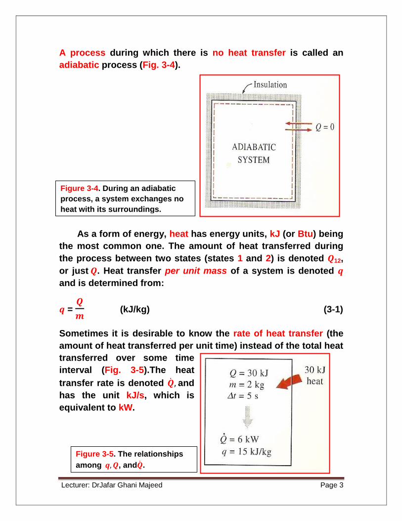
A process during which there is no heat transfer is called an

adiabatic process (Fig. 3-4).

As a form of energy, heat has energy units, kJ (or Btu) being

the most common one. The amount of heat transferred during

the process between two states (states 1 and 2) is denoted 𝑸12,

or just 𝑸. Heat transfer per unit mass of a system is denoted 𝒒

and is determined from:

𝒒 = 𝑸

𝒎 (kJ/kg) (3-1)

Sometimes it is desirable to know the rate of heat transfer (the

amount of heat transferred per unit time) instead of the total heat

transferred over some time

interval (Fig. 3-5).The heat

transfer rate is denoted 𝑸 , and

has the unit kJ/s, which is

equivalent to kW.

Figure 3-4. During an adiabatic

process, a system exchanges no

heat with its surroundings.

Figure 3-5. The relationships

among 𝒒, 𝑸, and𝑸 .

Lecturer: DrJafar Ghani Majeed Page 4

The universally accepted sign convention for heat is as follows:

Heat transfer to a system is positive, and heat transfer from a

system is negative (Fig. 3-6).

3-2. Work

Work, like heat, is an energy interaction between a system and

its surroundings. As mentioned earlier, energy can cross the

boundary of a closed system in the form of heat or work.

Therefore, if the energy crossing the boundary is not heat, it

must be work (Fig. 3-7).

Figure 3-6. Sign convention for

heat: positive if to the system,

negative if from the system.

Figure 3-7. An energy

interaction which is not

heat is work.

Lecturer: DrJafar Ghani Majeed Page 5

Work is also a form of energy like heat and, therefore, has

energy units such as kJ.The work done during a process

between state 1 and 2 is denoted 𝑾12, or simply 𝑾. The work

done per unit mass of the system is denoted 𝒘 and is defined

as:

𝒘 = 𝑾

𝒎 (kJ/kg) (3-2)

The work done per unit time is called power and denoted

𝑾 (Fig.3-8). The unit of power is kJ/s, or kW.

The production of work by a system is viewed as a

desirable, positive effect and the consumption of work as an

undesirable, negative effect. The sign convention for work

adapted in this text reflects this philosophy: Work done by a

system is positive, and work done on a system is negative

(Fig.3-9).

Figure 3-8. The relationships

among 𝒘, 𝑾, and 𝑾 .

Lecturer: DrJafar Ghani Majeed Page 6

Heat and work are interactions between a system and its

surroundings, and there are many similarities between the two:

1. Both are recognized at the boundaries of the system as they

cross them. That is, both heat and work are boundary

phenomena.

2. Systems possess energy, but not heat or work. That is, heat

and work are transient phenomena.

3. Both are associated with a process, not a state. Unlike

properties, heat or work has no meaning at a state.

4. Both are path functions (i.e., their magnitudes depend on the

path followed during a process as well as the end states).

Figure 3-9. Sign convention

for heat and work.

Lecturer: DrJafar Ghani Majeed Page 7

Example 3-3. (3-4)

A well-insulated electric oven is being heated through its

heating element. If the entire oven, including the heating

element, is taken to be the system, determine whether this is a

heat or work interaction.

Solution

For this problem the interior surfaces of the oven form the

system boundary, as shown in Fig. 3-13. The energy content of

the oven obviously increases during this process, as evidence

by a rise in temperature. This energy transfer to the oven is not

caused by a temperature difference between the oven and the

surrounding air. It is caused by negatively charged particles

called electrons crossing the system boundary and thus doing

work. Therefore, this is a work interaction.

Figure 3-13. Schematic for

Example 3-3.

Lecturer: DrJafar Ghani Majeed Page 8

Example 3-4. (3-5)

Answer the equation in Example 3-3 if the system is taken as

only the air in the oven without the heating element.

Solution

This time the system boundary will include the outer surface of

the heating element and will not cut through it, as shown in Fig.

3-14. Therefore, no electrons will be crossing the system

boundary at any point. Instead, the energy generated in the

interior of the heating element will be transferred to the air

around it as a result of the temperature difference between the

heating element and the air in the oven. Therefore, this is a heat

transfer process.

For both cases, the amount of energy transfer to the air is

the same. These two examples show that the same interaction

can be heat or work depending on how the system is selected.

Figure 3-14. Schematic for

Example 3-4.

Lecturer: DrJafar Ghani Majeed Page 9
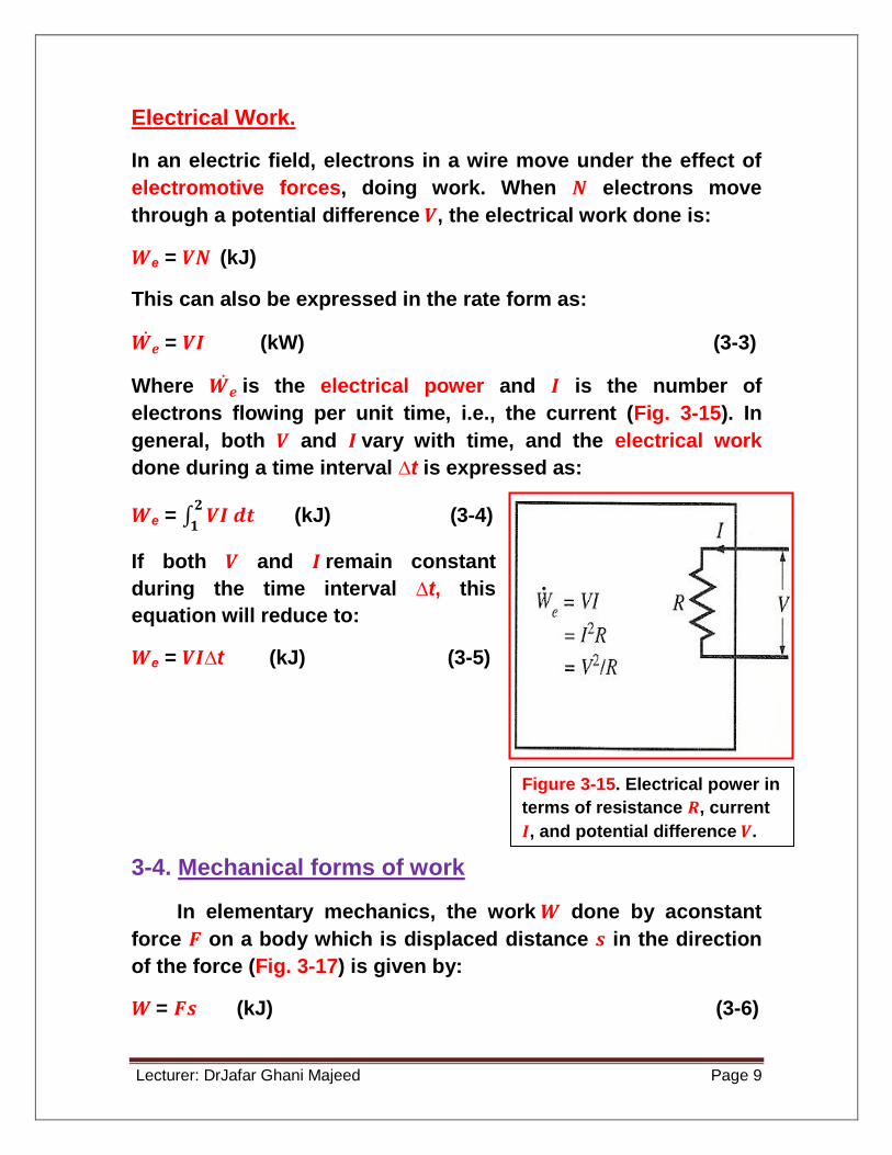
Electrical Work.

In an electric field, electrons in a wire move under the effect of

electromotive forces, doing work. When 𝑵 electrons move

through a potential difference 𝑽, the electrical work done is:

𝑾e = 𝑽𝑵 (kJ)

This can also be expressed in the rate form as:

𝑾𝒆 = 𝑽𝑰 (kW) (3-3)

Where 𝑾𝒆 is the electrical power and 𝑰 is the number of

electrons flowing per unit time, i.e., the current (Fig. 3-15). In

general, both 𝑽 and 𝑰 vary with time, and the electrical work

done during a time interval ∆t is expressed as:

𝑾e = 𝑽𝑰 𝒅𝒕𝟐

𝟏 (kJ) (3-4)

If both 𝑽 and 𝑰 remain constant

during the time interval ∆t, this

equation will reduce to:

𝑾e = 𝑽𝑰∆t (kJ) (3-5)

3-4. Mechanical forms of work

In elementary mechanics, the work 𝑾 done by aconstant

force 𝑭 on a body which is displaced distance 𝒔 in the direction

of the force (Fig. 3-17) is given by:

𝑾 = 𝑭𝒔 (kJ) (3-6)

Figure 3-15. Electrical power in

terms of resistance 𝑹, current

𝑰, and potential difference 𝑽.

Lecturer: DrJafar Ghani Majeed Page 10

If the force 𝑭 is not constant,

the work done is obtained by

adding (i.e., integrating) the

differential amount of work

(force times the differential

displacement 𝒅𝒔):

𝑾 = 𝑭 𝒅𝒔𝟐

𝟏 (kJ) (3-7)

In many thermodynamic problems, mechanical work is the

only form of work involved. It is associated with the movement

of the boundary of a system or with the movement of the entire

system as a whole. Some common forms of mechanical work

are discussed below.

1. Moving boundary work

One form of mechanical work frequently encountered in

practice is associated with the expansion or compression of a

gas in a piston-cylinder device. The expansion and compression

work is often called moving boundary work, or simply boundary

work (Fig. 3-19).

Figure 3-17. The work done is

proportional to the force applied (𝑭)

and the distance traveled (𝒔).

Figure 3-19. The work associated

with a moving boundary is called

boundary work.

Lecturer: DrJafar Ghani Majeed Page 11

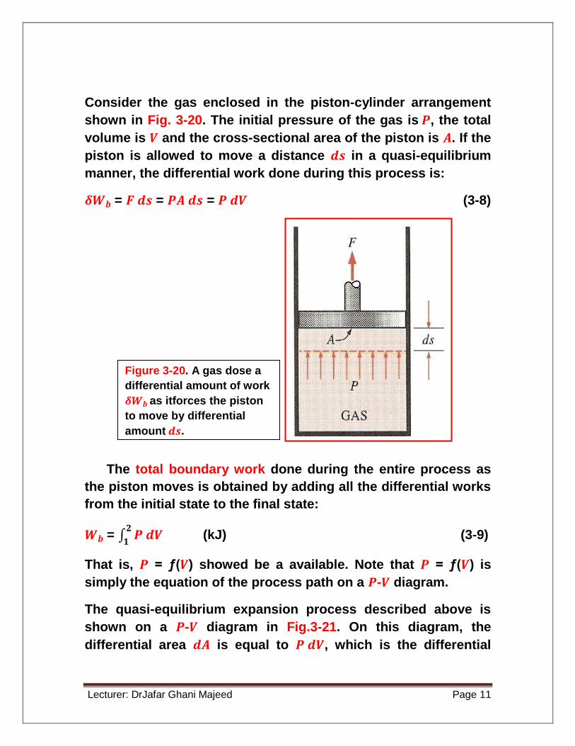
Consider the gas enclosed in the piston-cylinder arrangement

shown in Fig. 3-20. The initial pressure of the gas is 𝑷, the total

volume is 𝑽 and the cross-sectional area of the piston is 𝑨. If the

piston is allowed to move a distance 𝒅𝒔 in a quasi-equilibrium

manner, the differential work done during this process is:

𝜹𝑾𝒃 = 𝑭 𝒅𝒔 = 𝑷𝑨 𝒅𝒔 = 𝑷 𝒅𝑽 (3-8)

The total boundary work done during the entire process as

the piston moves is obtained by adding all the differential works

from the initial state to the final state:

𝑾𝒃 = 𝑷 𝒅𝑽𝟐

𝟏 (kJ) (3-9)

That is, 𝑷 = ƒ(𝑽) showed be a available. Note that 𝑷 = ƒ(𝑽) is

simply the equation of the process path on a 𝑷-𝑽 diagram.

The quasi-equilibrium expansion process described above is

shown on a 𝑷-𝑽 diagram in Fig.3-21. On this diagram, the

differential area 𝒅𝑨 is equal to 𝑷 𝒅𝑽, which is the differential

Figure 3-20. A gas dose a

differential amount of work

𝜹𝑾𝒃 as itforces the piston

to move by differential

amount 𝒅𝒔.

Lecturer: DrJafar Ghani Majeed Page 12

work. The total area 𝑨 under the process curve 1-2 is obtained

by adding these differential areas:

Area = 𝑨 = 𝒅𝑨𝟐

𝟏 = 𝑷 𝒅𝑽

𝟐

𝟏

A comparison of this equation with Eq. 3-9 reveals that the area

under the process curve on a 𝑷-𝑽 diagram is equal, in

magnitude, to the work done during a quasi-equilibrium

expansion or compression process of a closed system. (On the

𝑷-𝒗 diagram, it represents the boundary work done per unit

mass).

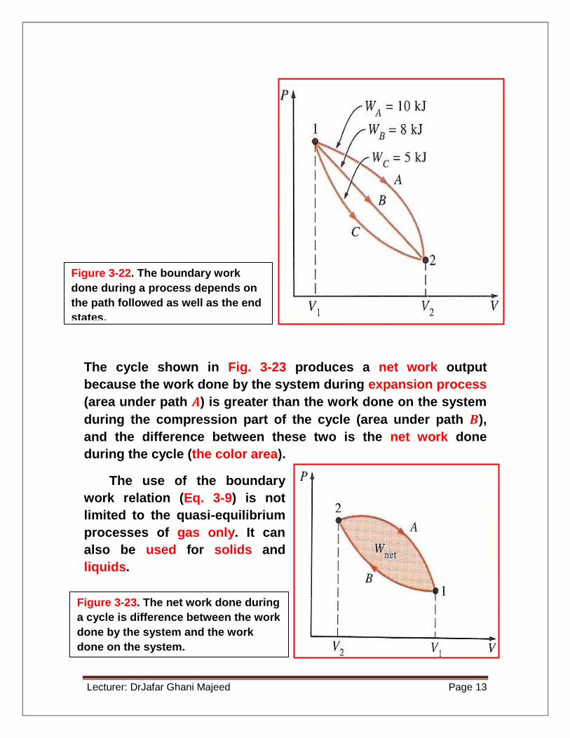
A gas can follow several different paths as it expands from state

1 to state 2. In general, each path will have a different area

underneath it, and since this area represents the magnitude of

the work, the work done will be different for each process (Fig.3-

22). This is expected since work is path function (i.e., it depends

on the path followed as well as the end states).

Figure 3-21. The area under

the process curve on a 𝑷-

𝑽 diagram represents the

boundary work.

Lecturer: DrJafar Ghani Majeed Page 13

The cycle shown in Fig. 3-23 produces a net work output

because the work done by the system during expansion process

(area under path 𝑨) is greater than the work done on the system

during the compression part of the cycle (area under path 𝑩),

and the difference between these two is the net work done

during the cycle (the color area).

The use of the boundary

work relation (Eq. 3-9) is not

limited to the quasi-equilibrium

processes of gas only. It can

also be used for solids and

liquids.

Figure 3-22. The boundary work

done during a process depends on

the path followed as well as the end

states.

Figure 3-23. The net work done during

a cycle is difference between the work

done by the system and the work

done on the system.

Lecturer: DrJafar Ghani Majeed Page 14

Example 3-6. (3-7)

A rigid tank contains air at 500 kPa and 150℃. As a result of heat

transfer to the surroundings, the temperature and pressure

inside the tank drop to 65℃ and 400 kPa, respectively. Determine

the boundary work done during this process.

Solution

A sketch of the system and

the 𝑷-𝑽 diagram of the

process are shown in Fig. 3-

24. Assuming the process to

be quasi-equilibrium, the

boundary work can be

determined from Eq. 3-9:

𝟎

𝑾𝒃 = 𝑷 𝒅𝑽𝟐

𝟏 = 0

This is expected since a rigid tank has a constant volume and

𝒅𝑽 = 0 in the above equation. Therefore, there is no boundary

done during this process. That is, the boundary work done

during a constant-volume process is always zero. This is also

evident from the 𝑷-𝑽 diagramof the process (the area under the

process curve is zero).

Example 3-7. (3-8)

A frictionless piston-cylinder device contains 10 Ibm of water

vapor at 60 psia and 320℉. Heat is now added to the steam until

the temperature reaches 400℉. If the piston is not attached to a

Figure 3-24. Schematic and 𝑷-

𝑽 diagram for Example 3-6.

Lecturer: DrJafar Ghani Majeed Page 15

shaft and its mass is constant, determine the work done by the

steam during this process.

Solution

A sketch of the system and the 𝑷-𝑽 diagram of the process are

shown in Fig. 3-25. Even though it is not explicitly stated, the

pressure of the steam within the cylinder remains constant

during this process since both the atmospheric pressure and

the weight of the piston remain constant. Therefore, this is a

constant-pressure process, and from Eq. 3-9:

𝑾𝒃 = 𝑷 𝒅𝑽𝟐

𝟏 = 𝑷𝟎 𝒅𝑽

𝟐

𝟏 = 𝑷𝟎 (𝑽𝟐 - 𝑽𝟏)

or 𝑾𝒃 = 𝒎𝑷𝟎(𝒗𝟐 - 𝒗𝟏) (3-10)

since 𝑽 = 𝒎𝒗. From the superheated vapor table (Table A-6E),

the specific volumes are determined to be 𝒗𝟏 = 7.485 ft3/lbm at

state 1 (60 psia, 320℉) and 𝒗𝟐 = 8.353 ft3/lbm at state 2 (60 psia,

400℉). Substituting these values yields:

Figure 3-25. Schematic and 𝑷-𝑽

diagram for Example 3-7.

Lecturer: DrJafar Ghani Majeed Page 16

𝑾𝒃 = (10 lbm)(60 psia) [ (8.353 -7.485) ft3/lbm) ] 𝟏 𝐁𝐭𝐮

𝟓.𝟒𝟎𝟒 𝐩𝐬𝐢𝐚.𝐟𝐭𝟑

= 96.4 Btu

The positive sign indicates that the work is done by the system.

That is, the steam used 96.4 Btu of its energy to do this work.

The magnitude of this work could also be determined by

calculating the area under the process curve on the 𝑷-𝑽

diagram, which is 𝑷𝟎∆𝑽 for this case.

Example 3-8. (3-9)

A piston-cylinder device initially contains 0.4 m3 of air at 100 kPa

and 80℃. The air is now compressed to 0.1 m3 in such a way that

the temperature inside the cylinder remains constant. Determine

the work done during this process.

Solution

A sketch of the system and the 𝑷-𝑽 diagram of the process are

shown in Fig. 3-26. At the specified conditions, air can be

considered to be an ideal gas since it is at a high temperature

and low pressure relative to its critical-point values (𝑻cr = –147℃,

𝑷cr = 3390 kPa for nitrogen, the main constituent of air). For an

ideal gas at constant temperature 𝑻0,

Figure 3-26. Schematic and 𝑷-

𝑽 diagram for Example 3-8.

Lecturer: DrJafar Ghani Majeed Page 17

𝑷𝑽 = m𝑹𝑻0 = 𝑪 or 𝑷 = 𝑪

𝑽

where 𝑪 is a constant. Substituting this into Eq. 3-9, we have:

𝑾𝒃 = 𝑷 𝒅𝑽𝟐

𝟏 =

𝑪𝑽𝒅𝑽

𝟐

𝟏 = 𝑪

𝒅𝑽𝑽

𝟐

𝟏 = 𝑪 𝐥𝐧

𝑽𝟐𝑽𝟏

= 𝑷1𝑽1 𝐥𝐧𝑽𝟐𝑽𝟏

(3-11)

In the above equation, 𝑷1𝑽1 can be replace by 𝑷2𝑽2 or 𝒎𝑹𝑻0.

Also, 𝑽2/ 𝑽1 can be replaced by 𝑷2/ 𝑷1 for this case since 𝑷1𝑽1

= 𝑷2𝑽2. Substituting the numerical values into the above

equation yields:

𝑾𝒃 = (100 kPa)(0.4 m3) 𝐥𝐧𝐨.𝟏

𝟎.𝟒

𝟏𝐤𝐉

𝟏𝐤𝐏𝐚.𝐦𝟑 = – 55.45 kJ

The negative sign indicates that this work is done on the

system, which is always the case for compression process.

Example 3-9.

During expansion and compression processes of real gases,

pressure and volume are often related by 𝑷𝑽n = 𝑪, where 𝒏 and 𝑪

are constants. Aprocess of this kind is called a polytropic

process. Develop a general expression for the work done during

a polytropic process.

Solution

A sketch of the system and the 𝑷-𝑽 diagram of the process are

shown in Fig. 3-27. The pressure for a polytropic process can be

expressed as:

𝑷𝑽n = 𝑪

Substitution this relation into Eq. 3-9, we obtain:

Lecturer: DrJafar Ghani Majeed Page 18

𝑾𝒃 = 𝑷𝒅𝑽𝟐

𝟏 = 𝑪𝑽−𝒏 𝒅𝑽

𝟐

𝟏 =𝑪

𝑽𝟐−𝒏+𝟏

− 𝑽𝟏−𝒏+𝟏

−𝒏+𝟏 = 𝑷𝟐 𝑽𝟐−𝑷𝟏 𝑽𝟏

𝟏−𝒏 (3-12)

Since 𝑪 = 𝑷1𝑽𝟏𝒏 = 𝑷2𝑽𝟐

𝒏. For an ideal gas (𝑷𝑽 = 𝒎𝑹𝑻), this equation

can also be written as:

𝑾𝒃 = 𝒎𝑹( 𝑻𝟐−𝑻𝟏 )

𝟏−𝒏 (kJ) (3-13)

The special case of 𝒏 = 1 is equivalent to the isothermal process

discussed in the previous example.

2 Gravitational work

The gravitational work can be defined as the work done

by or against a gravitational force field. In a gravitational

field, the force acting on a body is:

𝑭 = 𝒎𝒈

Figure. 3-27. Schematic and 𝑷-𝑽 diagram

for Example 3-9.

Lecturer: DrJafar Ghani Majeed Page 19

Where 𝒎 is mass of thebody and 𝒈 is the acceleration of

gravity which is assumed to be constant. Then the work

required to raise this body from level 𝒛1 to level 𝒛2.

𝑾g = 𝑭𝒅𝒛𝟐

𝟏 = 𝒎𝒈 𝒅𝒛

𝟐

𝟏 = 𝒎𝒈 (𝒛2 – 𝒛1) (kJ) (3-14)

𝐰𝐡𝐞𝐫𝐞 𝒛2 – 𝒛1 is the vertical distance traveled (Fig. 3-28). This

expression is easily recognized as the change in potential

energy. We conclude from Eq. 3-14 that the gravitational work

depends on the end states only and is independent of the

path followed.

Example 3-10.

Determine the work done by a person to lift a 50-lbm suitcase

shown in Fig.3-29 by 1 ft.

Solution

By assuming a standard gravitation and using Eq. 3-14, the work

done is:

𝑾g = 𝒎𝒈 (𝒛2 – 𝒛1)

𝑾g = (50 lbm)(32.174 ft/s2)(1 ft) 𝟏 𝐁𝐭𝐮

𝟐𝟓.𝟎𝟑𝟕 𝐟𝐭𝟐/𝐬𝟐 = 0.064 Btu

Figure 3-28. Vehicles required

more power (gravitational work

per unit time) as they climb a hill.

Lecturer: DrJafar Ghani Majeed Page 20

That is, 0.064 Btu of work is needed to perform this task. The

potential energy of the system (the suitcase) increases by 0.064

Btu during this process.

3 Accelerational work

The work associated with a change in velocity of a

system is defined as the accelerational work. The

accelerational work required to accelerate a body of mass 𝒎

from an initial velocity of 𝐕1 to final velocity 𝐕2 (Fig. 3-30) is

determined from the definition of acceleration and Newton’s

second law:

𝑭 = 𝒎𝒂

𝒂 = 𝒅𝐕

𝒅𝒕

𝑭 = 𝒎𝒅𝐕

𝒅𝒕

The differential displacement 𝒅𝒔 is related to velocity 𝐕

by: 𝐕 = 𝒅𝒔𝒅𝒕

𝒅𝒔 = 𝐕 𝒅𝒕

Substituting the 𝑭 and 𝒅𝒔 relations into the expression

(Eq. 3-7), we obtain:

Figure 3-29. Schematic for

Example 3-10.

Lecturer: DrJafar Ghani Majeed Page 21

𝑾a = 𝑭𝒅𝒔𝟐

𝟏 = 𝒎

𝒅𝑽

𝒅𝒕

𝟐

𝟏 (𝐕𝒅𝒕)

= 𝒎 𝐕 𝒅𝐕𝟐

𝟏 =

𝟏

𝟐𝒎 (𝐕𝟐

𝟐 - 𝐕𝟏𝟐) (kJ) (3-15)

The work done to accelerate a body is independent of

path and is equivalent to the

change in the kinetic energy

of the body.

The sign of accelerational

work is determined by

inspection: positive if done

by the system and negative if

done on the system.

Example 3-11.

Determine the power required to accelerate a 900kg car shown

in Fig. 3-31 from rest to a velocity of 80 km/h in 20 s on a level

road.

Figure 3-30. Vehicles require

more power (accelerational

work per unit time) as they

accelerate.

Figure 3-31. Schematic for

Example 3-11.

Lecturer: DrJafar Ghani Majeed Page 22

Solution

The accelerational work is determined from Eq. 3-15 to be:

𝑾a = 𝟏𝟐𝒎(𝐕𝟐

𝟐 - 𝐕𝟏𝟐)

𝑾a = 𝟏𝟐 (900 kg) [ (

𝟖𝟎𝟎𝟎𝟎 𝐦

𝟑𝟔𝟎𝟎 𝐬)𝟐– 0

2 ]

𝟏 𝐤𝐉

𝟏𝟎𝟎𝟎 𝐤𝐠.𝐦𝟐/𝐬𝟐

= 222.2 kJ

The average power is determined from:

𝑾𝒂 =

𝑾𝐚∆𝒕

= 𝟐𝟐𝟐.𝟐 𝐤𝐉

𝟐𝟎 𝐬= 11.1 kW (or 14.9 hp)

Where, kW = 1.341 hp

4 Shaft work

Energy transmission with a rotating shaft is very common in

engineering practice (Fig. 3-32). Often the torque 𝝉 applied

to the shaft is constant, which means that the force 𝑭

applied is also constant. For a specified constant torque,

the work done during 𝒏 revolutions is determined as

follows: A force 𝑭 acting through a moment arm 𝒓 generates

a torque 𝝉 (Fig. 3-33) which is determined from:

𝝉 = 𝑭𝒓 𝑭 = 𝝉 𝒓

This force acts through a distance 𝒔 which is related to the

radius 𝒓 by:

𝒔 = (2𝝅𝒓) 𝒏

Then the shaft work is determined from Eq. 3-6:

Lecturer: DrJafar Ghani Majeed Page 23

𝑾sh = 𝑭𝒔 = 𝝉𝒓 (2𝝅𝒓𝒏) = 2𝝅𝒏𝝉 (kJ) (3-16)

The power transmitted through the shat is the work done

per unit time, which can be expressed as:

𝑾 sh = 2𝝅𝒏 𝝉 (kW) (3-17)

Where 𝒏 is the number of revolutions per unit time.

The sign of the shaft work is also determined by

inspection: positive if done by the system and negative if

done on the system.

Example 3-12.

Determine the power transmitted through the shaft of a car when

the torque applied is 200 N.m and the shaft rotates at a rate of

4000 revolutions per minute (rpm).

Figure 3-32. Energy transmission

through rotating shafts is

commonly encountered in practice

Figure 3-33. Shaft work is

proportional to the torque applied

and the number of revolutions of

the shaft.

Lecturer: DrJafar Ghani Majeed Page 24

Solution

A sketch of the car is given in

Fig. 3-34. The shaft power is

determined from Eq. 3-17:

𝑾𝐬𝐡 = 2𝝅𝒏 𝝉 = (2 𝝅)(4000 𝟏

𝐦𝐢𝐧)(200N.m)

𝟏 𝐦𝐢𝐧

𝟔𝟎 𝐬

𝟏 𝐤𝐉

𝟏𝟎𝟎𝟎 𝐍.𝐦

= 83.7 kW (or 112.2 hp)

5 Spring work

It is common knowledge that when a force is applied on a

spring, the length of the spring changes (Fig. 3-35). When

the length of the spring changes by a differential amount

𝒅𝒙 under the influence of force 𝑭, the work done is:

𝜹𝑾spring = 𝑭 (3-18)

For liner elastic springs, the displacement 𝒙 is proportional to

the force 𝑭 applied (Fig. 3-36). That is,

𝑭 = 𝒌𝒙 (kN) (3-19)

Where,

𝒌 = spring constant (kN/m), 𝒙 = displacement of the spring (m)

𝒙 = 0 when 𝑭 = 0

Figure 3-34. Schematic for

Example 3-12.

Lecturer: DrJafar Ghani Majeed Page 25

Substituting Eq. 3-18 and integrating yield:

𝑾spring = 𝟏

𝟐𝒌( 𝒙𝟐

𝟐- 𝒙𝟏𝟐) (3-20)

Where,

𝒙1 = initial displacement of the spring

𝒙2 = final displacement of the spring

Example 3-13.

A piston-cylinder device contains 0.05 m3 of a gas initially at

200kPa. At this state a linear spring which has a spring constant

of 150 kN/m is touching the piston but exerting no force on it.

Now heat is transferred to the gas, causing the piston to rise and

to compress the spring until the volume inside the cylinder

doubles. If the cross-sectional area of the piston is 0.25 m2,

Figure 3-35. Elongation of a

spring under the influence of

a force.

Figure 3-36. The displacement

of a linear spring doubles

when the force is doubled.

Lecturer: DrJafar Ghani Majeed Page 26

determine (𝒂) the final pressure inside the cylinder, (𝒃) the total

work done by the gas, and (𝒄) the fraction of this work done

against the spring to compress it.

Solution

(a) A sketch of the system

and the 𝑷-𝑽 diagram of the

process are shown in Fig.

3-37. The enclosed

volume at the final state

is:

𝑽2 = 2 𝑽1 = (2)(0.05 m3)

= 0.1 m3

Then the displacement of

the piston (and the spring)

becomes:

𝒙 = ∆𝑽

𝑨 =

𝟎.𝟏−𝟎.𝟎𝟓 𝐦𝟑

𝟎.𝟐𝟓 𝐦𝟐 = 0.2 m

The force applied by the linear spring at the final state is

determined from Eq. 3-19 to be:

𝑭 = 𝒌𝒙 = (150 kN/m)(0.2 m) = 30 kN

The additional pressure applied by the spring on the gas at this

state is:

𝑷 = 𝑭

𝑨 =

𝟑𝟎 𝐤𝐍

𝟎.𝟐𝟓 𝐦𝟐 = 120 kPa

Under the effect of the spring, the pressure rises linearly from

200 kPa to:

Final pressure = (200 + 120) kPa = 320 kPa

Figure 3-37. Schematic and 𝑷-𝑽

diagram for Example 3-13.

Lecturer: DrJafar Ghani Majeed Page 27

(𝒃) From Fig. 3-37, the area under the process curve is

determined to be:

𝑾 = area = 𝟐𝟎𝟎+𝟑𝟐𝟎 𝐤𝐏𝐚

𝟐 [(0.1 – 0.05) 𝐦𝟑]

𝟏 𝐤𝐉

𝟏 𝐤𝐏𝐚.𝐦𝟑 = 13 kJ

The sign of the work is positive, mean that work is done by the

system.

(𝒄) The work represented by the rectangular area (region I) is

done against the piston and the atmosphere, and the work

represent by the triangular area (region II) is done against the

spring. Thus:

𝑾spring = 𝟏

𝟐 [(320 – 200) kPa] (0.05 m3)

𝟏 𝐤𝐉

𝟏 𝐤𝐏𝐚.𝐦𝟑 = 3 kJ

or this result could also be obtained from Eq. 3-20:

𝑾spring = 𝟏

𝟐𝒌( 𝒙𝟐

𝟐- 𝒙𝟏𝟐)

= 𝟏𝟐 (150 kN/m)[(0.2 m)

2– 0

2]

𝟏 𝐤𝐉

𝟏 𝐤𝐍.𝐦 = 3 kJ

3-5. The first law of thermodynamics

The first law of thermodynamics, also known as the

conservation of energy principle. Based on experimental

observations, the first law of thermodynamics states that energy

can be neither created nor destroyed; it can only change forms.

We all know that a rock at some elevation possesses some

potential energy, and part of this potential energy is converted

to kinetic energy as the rock falls (Fig. 3-39).

Consider first some processes that involve heat transfer but

no work interactions. As a result of heat transfer to the potato as

shown in (Fig. 3-40), the energy of the potato will increase. If we

Lecturer: DrJafar Ghani Majeed Page 28

disregard any mass transfer (moisture loss from the potato), the

increase in the total energy of the potato becomes equal to the

amount of heat transfer. Therefore, the conservation of energy

principle for this case can be expressed as:

𝑸 = ∆𝑬.

Consider the heating of water in a

pan on top of a range (Fig. 3-41). If

15kJ of heat is transferred to the

water from the heating element and 3

kJ of it is lost from the water to the

surrounding air, the increase in

energy of the water will be equal to

the net heat transfer to water, which

is 12 kJ. That is:

𝑸 = 𝑸net = ∆𝑬

Figure 3-39. Energy cannot

be created or destroyed; it

can only change forms.

Figure 3-40. The increase in the

energy of a potato in an oven is

equal to the amount of heat

transferred to it.

Figure 3-41. In the absence of

any work interactions, energy

change of a system is equal

to the net heat transfer.

Lecturer: DrJafar Ghani Majeed Page 29

The above conclusions can be summarized as follows: In the

absence of any work interactions between a system and its

surroundings, the amount of net heat transfer is equal to the

change in energy of a closed system. That is:

𝑸 = ∆𝑬 when 𝑾 = 0 (3-21)

Now consider a well-insulated

(i.e., adiabatic) room heated by

an electric heater as our system

(Fig.3-42). The conservation of

energy principle dictates that the

electrical work done on the

system must equal the increase

in energy of the system. That is:

– 𝑾e = ∆𝑬. when 𝑸 = 0

The negative sign is due to the

Sign convention that work done

on the system is negative.

Now let us replace the electric

heater with a paddle wheel (Fig. 3-

43). Again since there is no heat

interaction between the system

and its surroundings (𝑸 = 0), the

paddle-wheel work done on the

system must show up as an

increase in the energy of the

system. That is:

– 𝑾pw = ∆𝑬.

Figure 3-42. The work (electrical)

done on an adiabatic system is

equal to the increase in the

energy of the system.

Figure 3-43. The work (shaft) done on

an adiabatic system is equal to the

increase in the energy of the system.

Lecturer: DrJafar Ghani Majeed Page 30

Many of you have probably noticed that the temperature of air

rises when it is compressed (Fig. 3-44). This is because energy

is added to the air in the form of boundary work. In the absence

of any heat transfer (𝑸 = 0), the entire boundary work will be

stored in the air as part of its total energy. The conservation of

energy principle again requires that:

– 𝑾b = ∆𝑬.

It is clear from the foregoing

examples that for adiabatic processes,

the amount of work done is equal to

the change in the energy of a closed

system. That is:

– 𝑾 = ∆𝑬 when 𝑸 = 0 (3-22)

To generalize our conclusions, the first law of thermodynamics,

or the conservation of energy principle for a closed system or a

fixed mass, may be expressed as follows:

𝐍𝐞𝐭 𝐞𝐧𝐞𝐫𝐠𝐲 𝐭𝐚𝐧𝐬𝐟𝐞𝐫

𝐭𝐨 𝐨𝐫 𝐟𝐫𝐨𝐦 𝐭𝐡𝐞 𝐬𝐲𝐬𝐭𝐞𝐦𝐚𝐬 𝐡𝐞𝐚𝐭 𝐚𝐧𝐝 𝐰𝐨𝐫𝐤

= 𝐍𝐞𝐭 𝐢𝐧𝐜𝐞𝐚𝐬𝐞 𝐨𝐫 𝐝𝐞𝐜𝐫𝐞𝐚𝐬𝐞

𝐢𝐧 𝐭𝐡𝐞 𝐭𝐨𝐭𝐚𝐥 𝐞𝐧𝐞𝐫𝐠𝐲𝐨𝐟 𝐭𝐡𝐞 𝐬𝐲𝐬𝐭𝐞𝐦

or 𝑸 – 𝑾 = ∆𝑬 (3-23)

where

𝑸 = net heat transfer across system boundaries (= 𝑸𝐢𝐧 – 𝑸𝐨𝐮𝐭)

Figure 3-44. The work (boundary)

done on an adiabatic system is

equal to the increase in the

energy of the system.

Lecturer: DrJafar Ghani Majeed Page 31

𝑾 = net work done in all forms (= 𝑾𝐨𝐮𝐭– 𝑾𝐢𝐧)

∆𝑬 = net change in total energy of system, 𝑬2 – 𝑬1

The total energy 𝑬 of a system is considered to consist of three

parts: internal energy 𝑼, kinetic energy KE, and potential energy

PE.

Then the change in total energy of a system during a process

can be expressed:

∆𝑬 = ∆𝑼 + ∆𝐊𝐄 + ∆𝐏𝐄 (kJ) (3-24)

Substituting this relation into Eq. 3-23, we obtain:

𝑸 – 𝑾 = ∆𝑼 + ∆𝐊𝐄 + ∆𝐏𝐄 (kJ) (3-25)

Where ∆𝑼 = 𝒎(𝒖2 – 𝒖1)

∆𝐊𝐄 = 𝟏

𝟐𝒎(𝑽𝟐

𝟐–𝑽𝟏𝟐)

∆𝐏𝐄 = 𝒎𝒈(𝒛2 – 𝒛1)

Most closed systems encountered

in practice are stationary, i.e., they do

not involve any changes in their

velocity or the elevation of their center

of gravity during a process (Fig. 3-46).

Thus for stationary closed systems,

the change in kinetic and potential

energies are negligible (that

∆𝐊𝐄 = ∆𝐏𝐄 = 0), and the first-law

relation reduces to:

𝑸 – 𝑾 = ∆𝑼 (kJ) (3-26)

Figure 3-46. For stationary

systems, ∆𝐊𝐄 = ∆𝐏𝐄 = 0; thus

∆𝑬 = ∆𝑼.

Lecturer: DrJafar Ghani Majeed Page 32

Sometimes it is convenient to consider the work term in two

parts: 𝑸 – 𝑾other, where 𝑾other represents all forms of work except

the boundary work. The first law takes the following form:

𝑸 – 𝑾other – 𝑾b = ∆𝑬 (kJ) (3-27)

Other forms of the first-law relation

The first-law relation for closed systems can be written in

various forms (Fig. 3-47). Dividing Eq. 3-23 by the mass of the

system gives:

𝒒 – 𝒘 = ∆𝒆 (kJ/kg) (3-28)

The rate form of the first-law is obtained by dividing Eq. 3-23 by

the time interval ∆𝒕 and taking the limit as ∆𝒕 0. It yields:

𝑸 – 𝑾 = 𝒅𝑬

𝒅𝒕 (kW) (3-29)

Where, 𝑸 is the rate of net heat transfer, 𝑾 is the power, and

𝒅𝑬 𝒅𝒕 is the rate of change of total energy.

Equation 3-23 can be expressed in the differential form as:

𝜹𝑸 – 𝜹𝑾 = 𝒅𝑬 (kJ) (3-30)

or 𝜹𝒒 – 𝜹𝒘 = 𝒅𝒆 (kJ/kg) (3-31)

Figure 3-47. Various forms of

the first-law relation for

closed systems.

Lecturer: DrJafar Ghani Majeed Page 33

For a cyclic process, the initial and final states are identical,

and therefore ∆𝑬 = 𝑬2 – 𝑬1 = 0. Then the first-law relation for a

cycle simplifies to:

𝑸 – 𝑾 = 0 (kJ) (3-32)

That is, the net heat transfer and the net work done during a

cycle must be equal (Fig. 3-48).

Example 3-14.

A rigid tank contains a hot fluid which is cooled while being

stirred by a paddle wheel. Initially, the internal energy of the fluid

is 800 kJ. During the cooling process, the fluid loses 500 kJ of

heat, and the paddle wheel does 100 kJ of work on the fluid.

Determine the final internal energy of the fluid. Neglect the

energy stored in the paddle wheel.

Solution

We choose the fluid in the tank as our system. The system

boundaries are indicated in Fig. 3-49. By applying the

conservation of energy principle as given by Eq. 3-25 to this

process, 𝑼2 is determined to be:

Figure 3-48. For a cycle ∆𝑬

= 0, thus 𝑸 = 𝑾.

Lecturer: DrJafar Ghani Majeed Page 34

𝟎 𝟎

𝑸 – 𝑾 = ∆𝑼 + ∆𝐊𝐄 + ∆𝐏𝐄

= ∆𝑼 = 𝑼2 – 𝑼1

– 500 kJ – (– 100 kJ) = 𝑼2 – 800 kJ

𝑼2 = 400 kJ

3-6. A systematic approach to problem solving

Thermodynamic problems,

particularly the complicated

ones, also require a systematic

approach. By using a step-by-

step approach, an engineer can

solve a series of simple

problems instead of one large,

formidable problem (Fig. 3-50).

The proper approach to solving

thermodynamic problems is

illustrated below with the help of

a sample problem.

Sample problem

A 0.1 m3 rigid tank contains steam initially at 500 kPa and 200℃.

The steam is now allowed to cool until its temperature drops to

50℃. Determine the amount of heat transfer during this process

and the final pressure in the tank.

Figure 3-49. Schematic for

Example 3-14.

Figure 3-50. A step-by-step

approach can greatly simplify

problem solving.

Lecturer: DrJafar Ghani Majeed Page 35

Step 1: Draw a sketch and identify the system (Fig. 3-51):

Step 2: List the given information on the sketch (Fig. 3.52):

Step 3: Check for special processes (Fig. 3-53):

In our case, both the temperature and the

pressure vary but the specific volume

remains constant since rigid tanks have a

fixed volume (𝑽 = constant), and the mass

is fixed (𝒎 = constant).

Figure 3-51. Draw a sketch

of the system and system

boundaries.

Figure 3-52. List the given

information on the sketch.

Figure 3-53. Look for

simplifications.

Lecturer: DrJafar Ghani Majeed Page 36

Step 4: State any assumptions (Fig. 3-54):

The system in our case can be

assumed to be stationary since

there is no indication to the

contrary. Thus the changes in

kinetic and potential energies

can be neglected.

Step 5: Apply the conservation equations (Fig. 3-55):

Step 6: Draw a process diagram (Fig. 3-56):

Process diagrams, such as the 𝑷-𝒗

or 𝑻-𝒗 diagrams, are extremely

helpful in visualizing the initial and

final states of a system and the path

of the process.

Figure 3-54. Make realistic

assumptions, if necessary.

Figure 3-55. Apply relevant

conservation equations

and simplify them.

Figure 3-56. Show the

process on a property

diagram.

Lecturer: DrJafar Ghani Majeed Page 37

Step 7: Determine the required properties and unknowns (Fig. 3-

57):

Steam exists as a superheated vapor at the state 1 since the

temperature is greater the saturation temperature a the given

pressure [that is, 200℃ > 𝑻sat @ 500 kPa = 151.9℃ (Table A-5)].

Example 3-15.

A piston-cylinder device contains 25 g of saturated water vapor

which is maintained at a constant pressure of 300 kPa. A

resistance heater within the cylinder is turned on and passes a

current of 0.2 A for 5 min from a 120 V source. AT the same time,

a heat loss of 307 kJ occurs. (𝒂) Show that for a closed system

the boundary work 𝑾b and the change in internal energy ∆𝑼 in

the first-law relation can be combined into one term, ∆𝑯, for a

Figure 3-57. Determine the required

properties, and solve the problem.

(Table A-4)

(Table A-4)

(Table A-6)

= 12.349 kPa

kkkkkkPakP

a

(Table A-6)

= – 553.4 kJ

Lecturer: DrJafar Ghani Majeed Page 38

constant-pressure process. (𝒃) determine the final temperature

of the steam.

Solution

(𝒂) Neglecting the changes in kinetic and potential energies and

expressing the work as the sum of boundary and other forms of

work, Eq.3-25 simplifies to:

𝟎 𝟎

𝑸 – 𝑾 = ∆𝑼 + ∆𝐊𝐄 + ∆𝐏𝐄 when 𝑾 = 𝑾other + 𝑾b then:

𝑸 – 𝑾other – 𝑾b = ∆𝑼 = 𝑼2 – 𝑼1

For a constant-pressure process, the boundary work is given by

Eq. 3-10 as:

𝑾b = 𝑷0(𝑽2 – 𝑽1). Substituting this into the above relation gives:

𝑸 – 𝑾other – 𝑷0(𝑽2 – 𝑽1) = 𝑼2 – 𝑼1

But

𝑷0 = 𝑷2 = 𝑷1 𝑸 – 𝑾other = (𝑼2 + 𝑷2 𝑽2) – (𝑼1 + 𝑷1 𝑽1)

Figure 3-58. Schematic and

diagram for Example 3-15.

Lecturer: DrJafar Ghani Majeed Page 39

Also 𝑯 = 𝑼 + 𝑷𝑽, and thus:

𝑸 – 𝑾other = 𝑯2 – 𝑯1 (kJ) (3-33)

which is the desired relation (Fig. 3-59):

(𝒃) For our case, the only other form of work is the electrical

work which, which can be determined from Eq. 3-5:

𝑾e = 𝑽𝑰∆𝒕 = (120 V)(0.2 A)(300 s) 𝟏 𝐤𝐉

𝟏𝟎𝟎𝟎 𝐕𝐀.𝐬 = 7.2 kJ

State 1: 𝑷𝟏 = 𝟑𝟎𝟎 𝐤𝐏𝐚

𝐬𝐚𝐭. 𝐯𝐚𝐩𝐨𝐫 𝒉1 = 𝒉g @ 300KPa = 2725.3 kJ/kg (Table A-5)

The enthalpy at the final state can be determined from the

conservation of energy relation for closed systems undergoing a

constant-pressure process (Eq. 3-33):

𝑸 – 𝑾e = 𝒎(𝒉2 – 𝒉1)

– 3.7 kJ – (–7.2 kJ) = (0.025 kg)( 𝒉2 – 2725.3 kJ/kg)

𝒉2 = 2865.3 kJ/kg

Figure 3-59.For a closed

system undergoing a quasi-

equilibrium 𝑷 = constant

process, ∆𝑼 + 𝑾b = ∆𝑯

Lecturer: DrJafar Ghani Majeed Page 40

𝐬𝐢𝐧𝐞 𝒉2 > 𝒉1, the state 2 is superheated water

State 2: 𝑷𝟐 = 𝟑𝟎𝟎 𝐤𝐏𝐚

𝒉𝟐 = 𝟐𝟖𝟔𝟓.𝟑 𝐤𝐉/𝐤𝐠 𝑻2 = 200℃ (Table A- 6)

Example 3-16.

𝐀 𝐫𝐢𝐠𝐢𝐝 𝐭𝐚𝐧𝐤 𝐰𝐢𝐭𝐡 𝐚 𝐯𝐨𝐥𝐮𝐦𝐞 of 3 ft3 is initially filled with

refrigerant-12 at 120 psia and 140℉. The refrigerant is now

cooled to 20℉. Determine (a) the mass of the refrigerant, (b) the

final pressure in the tank, and (c) the heat transferred from the

refrigerant.

Solution.

A sketch of the system and the 𝑻-𝒗 diagram of the process are

given in Fig. 3-60.

(a) To find the mass, we need to know the specific volume of the

refrigerant at the initial state, which is determined from Table A-

13E:

State 1: 𝑷1 = 120 psia 𝒗𝟏= 0.389 ft3/Ibm

𝑻1 = 140℉ 𝒖1 = 86.098 Btu/Ibm

Thus, m = 𝑽

𝒗𝟏 =

𝟑 𝐟𝐭𝟑

𝟎.𝟑𝟖𝟗 𝐟𝐭𝟑/𝐈𝐛𝐦 = 7.71 Ibm

(𝒃) This is a constant-volume process, and therefore 𝒗2 = 𝒗1 =

0.389 ft3/Ibm.

At 20℉:

𝒗f = 0.01130 ft3/Ibm 𝒖f = 12.79 Btu/Ibm

𝒗g = 1.0988 ft3/Ibm 𝒖g = 72.12 But/Ibm

(Table A-11E)

Lecturer: DrJafar Ghani Majeed Page 41

The refrigerant is a saturated liquid-vapor mixture at the final

state since 𝒗f < 𝒗2 < 𝒗g. Therefore, the pressure must be the

saturation pressure at 20℉:

𝑷2 = 𝑷sat @ 20F = 35.736 psia (Table A-11E)

(𝒄) Assuming ∆𝐊𝐄 = ∆𝐏𝐄 = 0 and realizing that there are no

boundary or other forms of work interactions, we see that the

first-law relation (Eq. 3-25) simplifies to:

𝟎 𝟎 𝟎

𝑸 – 𝑾 = ∆𝑼 + ∆𝐊𝐄 + ∆𝐏𝐄

𝑸 = ∆𝑼 = 𝒎(𝒖2 – 𝒖1)

To determine 𝒖2, we first need to know the quality x2 at the final

state. It is determined from:

x2 = 𝒗𝟐− 𝒗𝒇

𝒗𝒇𝒈 =

[ 𝟎.𝟑𝟖𝟗−𝟎.𝟎𝟏𝟏𝟑 𝐦𝟑/𝐤𝐠]

[ 𝟏.𝟎𝟗𝟖𝟖−𝟎.𝟎𝟏𝟏𝟑 𝐦𝟑/𝐤𝐠] = 0.348

Figure 3-60. Schematic and 𝑻-𝒗 diagram

for Example 3-16.

Lecturer: DrJafar Ghani Majeed Page 42

That is, 34.8 percent of the refrigerant is in the vapor form at the

final state. Then,

𝒖2 = 𝒖f + x2𝒖fg

= 12.79 Btu/Ibm + (0.348)[(72.12 – 12.79) Btu/Ibm]

= 33.44 Btu/Ibm

Finally, substituting these values into the first-law relation will

give us the heat transfer:

𝑸 = (7.71 Ibm)[(33.44 – 86.098) Btu/Ibm]

= – 406.0 Btu

3-7. Specific heats

We know from experience that it takes different amounts of

energy to raise the temperature of identical masses of different

substances by one degree (Fig. 3-62). Therefore, it is desirable

to have a property that will enable us to compare the energy

storage capability of various substances. This property is the

specific heat.

The specific heat is defined as

the energy required to raise the

temperature of a unit mass of a

substance by one degree (Fig. 3-

63). In thermodynamics, we are

interested in two kinds of specific

heats: specific heat at constant

volume 𝑪𝒗 and specific heat at

costant pressure 𝑪𝒑.

Figure 3-62. It takes different

amounts of energy to raise the

temperature of different

substances by the same amount.

Lecturer: DrJafar Ghani Majeed Page 43

The specific heat at constant pressure 𝑪𝒑 is always greater than

𝑪𝒗 because at constant pressure

the system is allowed to expand

and the energy for this expansion

work must also be supplied to the

system as shown in (Fig. 3-64).

From the definition of 𝑪𝒗, this

energy must be equal to 𝑪𝒗 𝒅𝑻,

where 𝒅𝑻 is the differential change

in temperature. Thus,

𝑪𝒗 𝒅𝑻 = 𝒅𝒖 at constant volume

𝑪𝒗 = 𝝏𝒖

𝝏𝑻 𝒗

(3-34)

Similarly, an expression for

the specific heat at constant

pressure 𝑪𝒑 can be obtained

by considering a constant-

pressure process (𝒘b + ∆𝒖 =

∆𝒉).

It yields

𝑪𝒑 = 𝝏𝒉

𝝏𝑻 𝒑 (3-35)

A common unit for specific

heats is:

kJ/(kg.℃) or kJ/(kg.K),

these two units are identical

since ∆𝑻 (℃) = ∆𝑻 (𝐊)

Figure 3-63. Specific heat is

the energy required to raise

the temperature of a unit

mass of a substance by one

degree in a specific way.

Figure 3-64. Constant-volume

and constant-pressure specific

heats 𝑪𝒗 and 𝑪𝒑 (values given

are for helium gas).

Lecturer: DrJafar Ghani Majeed Page 44

Equations 3-34 and 3-35 are the defining equations for 𝑪𝒗 and

𝑪𝒑, and their interpretation is given in Fig. 3-65.

The energy required to raise the

temperatures of substance by

one degree will be different at

different temperatures and

pressures (Fig. 3-66). But the

difference usually not large.

The specific heats are sometimes given on a molar basis. They

are denoted by 𝑪 v and 𝑪 p and have the units kJ/(kmol.℃) or

kJ/(kmol.K).

3-8. Internal energy, enthalpy and specific heats of ideal

gases

We defines an ideal gas as a substance whose temperature,

pressure, and specific volume are related by:

Figure 3-65. Mathematical

definitions of 𝑪𝒑 and 𝑪𝒗.

Figure 3-66. The specific heat of

a substance changes with

temperature.

Lecturer: DrJafar Ghani Majeed Page 45

𝑷𝒗 = 𝑹𝑻

For ideal gas the internal energy is a function of the temperature

only. That is,

𝒖 = 𝒖(𝑻) (3-36)

In the Joule’s experiment, Joule submerged two tanks

connected with a pipe and a valve in a water bath, as shown in

Fig. 3-67. Since there was also no

work done, he concluded that the

internal energy of the air did not

change even though the volume

and the pressure changed.

Therefore, he reasoned, the

internal energy is a function of

temperature only and not a

function of pressure or specific

volume.

Using the definition of enthalpy

and the equation of state of an

ideal gas, we have:

𝒉 = 𝒖 + 𝑷𝒗𝑷𝒗 = 𝑹𝑻

𝒉 = 𝒖 + 𝑹𝑻

Since 𝑹 is constant and 𝒖 = 𝒖(𝑻), it follows that the enthalpy

of an ideal gas is also a function of temperature only:

𝒉 = 𝒉(𝑻) (3-37)

Since 𝒖 and 𝒉 depend only on temperature for an ideal gas,

the specific heats 𝑪𝒗 and 𝑪𝒑 also depend, at most, on

temperature only. Therefore, at a given temperature 𝒖, 𝒉, 𝑪𝒗, and

𝑪𝒑 of an ideal gas will have fixed values regardless of the

specific volume or pressure (Fig. 3-68).

Figure 3-67. Schematic of the

experimental apparatus used

by Joule.

Lecturer: DrJafar Ghani Majeed Page 46

Then the differential changes in the

internal energy and enthalpy of an

ideal gas can be expressed as:

𝒅𝒖 = 𝑪𝒗(𝑻) 𝒅𝑻 (3-38)

and 𝒅𝒉 = 𝑪𝒑(𝑻) 𝒅𝑻 (3-39)

The change in internal energy or

enthalpy for an ideal gas during a

Process from state 1 to state 2 is

Determined by integration these

equations:

∆𝒖 = 𝒖2 – 𝒖1 = 𝑪𝒗(𝑻) 𝒅𝑻𝟐

𝟏 (kJ/kg) (3-40)

and ∆𝒉 = 𝒉2 – 𝒉1 = 𝑪𝒑(𝑻) 𝒅𝑻𝟐

𝟏 (kJ/kg) (3-41)

At low pressures all real

gases approach ideal-gas

behavior, and therefore their

specific heats depend on

temperature only. The specific

heats of real gases at low

pressures are called ideal-gas

specific heats or zero pressure

specific heats, and are often

denoted 𝑪𝒑𝟎 and 𝑪𝒗𝟎 (Table A-2

𝒂, 𝒃, 𝒄). A plot of 𝑪 p0(𝑻) data for

some gases is given in Fig. 3-69.

Figure 3-68. For ideal gases, 𝒖,

𝒉, 𝑪𝒗, and 𝑪𝒑vary with

temperature only.

Figure 3-69. Ideal-gas constant –

pressure specific heats for some

gases (see Table A-2𝒄 for 𝑪 p0

equations).

Lecturer: DrJafar Ghani Majeed Page 47

Some observation can made from Fig. 3-69. First, the specific

heats of gases with complex molecules (molecules with two or

more atoms) are higher and increase with temperature. Also the

variation of specific heats with temperature is smooth and may

be approximated as linear over small temperature intervals ( a

few hundred or less). Then the specific heat functions in Eqs. 3-

40 and 3-41 can be replaced by the constant average specific

heat values. Now the integration in these equations can be

performed, yielding:

𝒖2 – 𝒖1 = 𝑪𝒗,𝐚𝐯(𝑻2 – 𝑻1) (kJ/kg) (3-42)

and 𝒉2 – 𝒉1 = 𝑪𝒑,𝐚𝐯(𝑻2 – 𝑻1) (kJ/kg) (3-43)

The specific heat values for some common gases are listed as a

function of temperature in Table A-2𝒃. The average specific

heats 𝑪𝒑,𝐚𝐯 and 𝑪𝒗,𝐚𝐯 are evaluated from this table at the

average temperature (𝑻2 + 𝑻1)/2, as shown in Fig. 3-71.

Another way of determining the

average specific heats is to evaluate

them at 𝑻1 and 𝑻2 and then take their

average. Usually both methods give

reasonably good results, and one is

not necessarily better than the other.

Another observation that can be

made from Fig. 3-69 is that the ideal-

gas specific heats of monatomic

gases such as argon, neon, and

helium remain constant over the

entire temperature range. Thus ∆𝒖

and ∆𝒉 of monatomic gases can

easily evaluated from Eqs. 3-42 and

3-43.

Figure 3-71. For small

temperature intervals, the

specific heats may be

assumed to vary linearly

with temperature.

Lecturer: DrJafar Ghani Majeed Page 48

Specific-heat relations of ideal gases

A special relationship between 𝑪𝒗 and 𝑪𝒑 for ideal gases can be

obtained by differentiating the relation 𝒉 = 𝒖 + 𝑹𝑻, which

yields:

𝒅𝒉 = 𝒅𝒖 + 𝑹𝒅𝑻

Replacing 𝒅𝒉 by 𝑪𝒑 𝒅𝑻 and 𝒅𝒖 by 𝑪𝒗 𝒅𝑻 and dividing the

resultant expression by 𝒅𝑻, we obtain:

𝑪𝒑 = 𝑪𝒗 + 𝑹 [kJ/(kg.K)] (3-44)

This is an important relationship for ideal gases since it enables

us to determine 𝑪𝒗 from a knowledge of 𝑪𝒑 and the gas

constant 𝑹.

When the specific heats are given on a molar basis, 𝑹 in the

above equation should be replaced by the universal gas

constant 𝑹u (Fig. 3-74). That is,

𝑪 p = 𝑪 v + 𝑹u [kJ/(kmol.K)] (3-45)

At this point, we introduce another ideal-gas property called

the specific heat ratio 𝒌, defined as:

𝒌 = 𝑪𝒑

𝑪𝒗 (3-46)

Figure 3-74. The 𝑪𝒑 of an

ideal gas can be determine

from a knowledge of 𝑪𝒗

and 𝑹.

Lecturer: DrJafar Ghani Majeed Page 49

The specific heat ratio (𝒌) also varies with temperature, but this

variation is very small. For monatomic gases, its value is

essentially constant at 𝒌 = 1.667. Many diatomic gases,

including air, have specific heat ratio of about 𝒌 = 1.4 at room

temperature.

Example 3-18.

Air at 300 K and 200 kPa is heated at constant pressure to 600 K.

Determine the change in internal energy of air per unit mass(∆𝒖

), using (a) data from the air table (Table A-17), (b) the functional

form of the specific heat (Table A-2c), and (c) the average

specific heat value (Table A-2b).

Solution.

Air can be considered to be an ideal gas since it is at a high

temperature and low pressure relative to its critical-point values

(𝑻cr = -147℃, 𝑷cr = 3390 kPa for nitrogen, the main constituent of

air). ∆𝒖 of ideal gases depends on the initial and final

temperatures only, and not on the type of process.

(a)

𝒖1 = 𝒖 @ 300 K = 214.07 kJ/kg

𝒖2 = 𝒖 @ 600 K = 434.78 kJ/kg

Thus, ∆𝒖 = 𝒖2 – 𝒖1 = (434.78 – 214.07) kJ/kg = 220.71 kJ/kg

(b)

The 𝑪 p(𝑻) of air is given in Table A-2c in the form of a third-

degree polynomial expressed as:

𝑪 p(𝑻) = a + bT + cT2 + dT3

(Table A-17)

Lecturer: DrJafar Ghani Majeed Page 50

Where a = 28.11, b = 0.1967 x 10⁻², c = 0.4802 x 10⁻⁵, d = -1.966 x

10-9. From Eq. 3-45,

𝑪 v(𝑻) = 𝑪 p – Ru = (a – Ru) + 𝒃𝑻 + 𝒄𝑻2 + 𝒅𝑻3

From Eq. 3-40,

∆𝒖 = 𝑪 𝟐

𝟏 v(𝑻) 𝒅𝑻

= [(𝒂 − 𝑹𝒖𝑻𝟐

𝑻𝟏) + 𝒃𝑻 + 𝒄𝑻𝟐 + 𝒅𝑻𝟑] 𝒅𝑻

Performing the integration and substitution the values, we

obtain:

∆𝒖 = 6447.15 kJ/kmol

The change in the internal energy on a unit-mass basis (∆𝒖) is

determined by dividing this value by the molar mass of air (Table

A-1):

∆𝒖 = ∆𝒖

𝑴 =

𝟔𝟒𝟒𝟕.𝟏𝟓 𝐤𝐉/𝐤𝐦𝐨𝐥

𝟐𝟖.𝟗𝟕 𝐤𝐠/𝐤𝐦𝐨𝐥 = 222.55 kJ/kg

This differs from the exact result by 0.8 percent:

% error = 𝟐𝟐𝟐.𝟓𝟓−𝟐𝟐𝟎.𝟕𝟏 𝐤𝐉/𝐤𝐠

(𝟐𝟐𝟎.𝟕𝟏) 𝐤𝐉/𝐤𝐠 x 100 ≅ 0.8 %

(c) The average value of the constant-volume specific heat 𝑪𝒗,𝐚𝐯

is determined from Table A-2b at the average temperature(𝑻2 +

𝑻1)/2 = (300 + 600) K/2 = 450 K to be:

𝑪𝒗,𝐚𝐯 = 𝑪𝒗 @ 450 K = 0.733 kJ/(kg.K) (Table A-2b)

Thus ∆𝒖 = 𝑪𝒗,𝐚𝐯(𝑻2 – 𝑻1) = [0.733 kJ/(kg.K)][(600 – 300) K]

= 219.9 kJ/kg

This answer differs the exact result (220.71 kJ/kg) by only 0.4

percent:

Lecturer: DrJafar Ghani Majeed Page 51

% error = 𝟐𝟐𝟎.𝟕𝟏−𝟐𝟏𝟗.𝟗 𝐤𝐉/𝐤𝐠

(𝟐𝟐𝟎.𝟕𝟏) 𝐤𝐉/𝐤𝐠 x 100 ≅ 0.4 %

Example 3-19.

An insulted rigid tank initially contains 1.5 Ibm of helium at 80℉

and 50 psia. A paddle wheel with a power rating of 0.02 hp is

operated within the tank for 30 min. Determine (a) the final

temperature and (b) the final pressure of the helium gas.

Solution.

A sketch of the system and the 𝑷-𝒗 diagram of the process are

shown in Fig. 3-75. The helium gas at the specified conditions

can be considered to be an ideal gas since it is at a very high

temperature relative to its critical-point temperature (𝑻cr = -

451℉ for helium Table A-1E).

(a) The amount of paddle-wheel work done on the system is:

𝑾pw = 𝑾 pw ∆t = (– 0.02 hp)(0.5 h)

𝟐𝟓𝟒𝟓 𝐁𝐭𝐮/𝐡

𝟏 𝐡𝐩 = – 25.45 Btu

Since, Wb = 0 (rigid tank have not moving boundaries)

𝑸 = 0 (insulated tank)

∆𝐊𝐄 = ∆𝐏𝐄 = 0 (The system is assumed to be stationary)

Then the conservation of energy equation for this closed system

reduces to:

𝟎 𝟎 𝟎 𝟎

𝑸 – Wpw – Wb = ∆U + ∆𝐊𝐄 + ∆𝐏𝐄

– Wpw = ∆U = m(u2 – u1) ≅ m𝑪𝒗,𝐚𝐯(𝑻2 – 𝑻1)

Lecturer: DrJafar Ghani Majeed Page 52

As we pointed out earlier, the ideal-gas specific heats of

monatomic gases (helium being one of them) are constant. The

𝑪𝒗 value of helium is determined from Table A-2Ea to be 𝑪𝒗 =

0.753 Btu/(Ibm.℉ ). Substituting this and other known quantities

into above energy equation, we obtain:

– (– 25.45 Btu) = (1.5 Ibm)(0.753 Btu/(Ibm.℉)(𝑻2 – 80℉)

𝑻2 = 102.5℉

(b) The final pressure is determined from the ideal-gas relation:

𝑷𝟏 𝑽𝟏

𝑻𝟏 =

𝑷𝟐𝑽𝟐

𝑻𝟐

Where 𝑽1 and 𝑽2 are identical and cancel. Then the final pressure

becomes:

𝟓𝟎 𝐩𝐬𝐢𝐚

𝟖𝟎+𝟒𝟔𝟎 𝐑 =

𝑷𝟐

𝟏𝟎𝟐.𝟓+𝟒𝟔𝟎 𝐑

𝑷𝟐 = 53.1 psia

Figure 3-75. Schematic and 𝑷-𝒗

diagram for Example 3-19.

Lecturer: DrJafar Ghani Majeed Page 53

Example 3-20.

A piston-cylinder device initially contains 0.5 m3 of nitrogen gas

at 400 kPa and 27℃. An electric heater within the device is

turned on and is allowed to pass a current of 2 A for 5 min from

a 120 V source. Nitrogen expands at constant pressure, and a

heat loss of 2800 J occurs during the process. Determine the

final temperature of the nitrogen, using data from the nitrogen

table (Table A-18).

Solution.

A sketch of the system and the P-V diagram of the process are

given in Fig. 3-76.

At the specified conditions, the nitrogen gas can be considered

to be an ideal gas since it is at a high temperature and low

Figure 3-76. Schematic and 𝑷-𝑽

diagram for Example 3-20.

Lecturer: DrJafar Ghani Majeed Page 54

pressure relative to its critical-point values (Tcr = –147℃, Pcr =

3390 kPa, Table A-1).

First, let us determine the electrical work done on the

nitrogen:

We = VI ∆t = (120 V)(2 A)(5 x 60 s) 𝟏 𝐤𝐉

𝟏𝟎𝟎𝟎 𝐕𝐀.𝐬 = – 72 kJ

The negative sign is added because the work is done on the

system.

The number of moles of nitrogen is determined from the

ideal-gas relation:

N = 𝑷𝟏𝑽𝟏

𝑹𝒖𝑻𝟏 =

𝟒𝟎𝟎 𝐤𝐏𝐚 (𝟎.𝟓 𝐦𝟑)

[𝟖.𝟑𝟏𝟒 𝐤𝐉/(𝐤𝐦𝐨𝐥.𝐊)](𝟑𝟎𝟎 𝐊) = 0.080 kmol

When gases other than air are involved, it is more convenient to

work with mole numbers instead of masses since all the u and h

data are given on a mole basis (Fig. 3-77). Assuming no change

in kinetic and potential energies ( ∆KE = ∆PE = 0), the

conservation of energy equation for this closed system can be

written as:

𝑸 – We – Wb = ∆U

For the constant- pressure process of a closed system, ∆U + Wb

is equivalent to ∆H. Thus,

𝑸 – We = ∆H = m(h2 – h1) = N(𝒉 2 – 𝒉 1)

From the nitrogen table, 𝒉 1 = 𝒉 @ 300 K = 8723 kJ/kmol. The only

unknown quantity in the above equation is 𝒉 2, and it is found to

be:

– 2.8 kJ – (– 72 kJ) = (0.08 kmol)( 𝒉 2 – 8723 kJ/kmol)

𝒉 2 = 9588 kJ/kmol

Lecturer: DrJafar Ghani Majeed Page 55

The temperature corresponding to this enthalpy value is:

T2 = 329.7 K = 56.7℃ (Table A-18)

3-9. Internal energy, enthalpy, and specific heats of

solids and liquids

A substance whose specific volume (or density) is constant is

called an incompressible substance. The specific volumes of

solids and liquids essentially remain constant during a process

(Fig. 3-79). Therefore, liquids and

solids can be approximated as

incompressible substances

without sacrificing much in

accuracy.

The constant-volume and

constant-pressure specific heats

are identical for incompressible

substances (Fig. 3-80).

Figure 3-77. Two equivalent ways of

determining the total enthalpy

change ∆H.

Figure 3-79. The specific volumes of

incompressible substances remain

constant during a process.

Lecturer: DrJafar Ghani Majeed Page 56

Therefore, for solids and liquids the subscripts on 𝑪𝒑 and 𝑪𝒗 can

be dropped, and both specific heats can be represented by a

single symbol 𝑪. That is,

𝑪𝒑 = 𝑪𝒗 = 𝑪 (3-47)

Specific heat values for several

common liquids and solids are given

in Table A-3.

Like those of ideal gases, the

specific heats of incompressible

substances depends on temperature

only. Thus the partial differentials in

the defining equation of 𝑪𝒗 (Eq. 3-34)

can be replaced by ordinary

differentials, which yields:

𝒅𝒖 = 𝑪𝒗 𝒅𝑻 = 𝑪(𝑻) 𝒅𝑻 (3-48)

The change in internal energy between state 1 and 2 is then

obtained by integration:

∆𝒖 = 𝒖2 – 𝒖1 = 𝑪(𝑻) 𝒅𝑻𝟐

𝟏 (kJ/kg) (3-49)

For small temperature intervals, a 𝑪 values at the average

temperature can be used and treated as a constant, yielding:

∆𝒖 ≅ 𝑪av(𝑻2 – 𝑻1) (kJ/kg) (3-50)

For enthalpy change of solids or liquids during process 1-2 can

be determined from the definition of enthalpy (𝒉 = 𝒖 + 𝑷𝒗) to be:

𝒉2 – 𝒉1 = (𝒖2 – 𝒖1) + 𝒗(𝑷2 – 𝑷1) (3-51)

since 𝒗1 = 𝒗2 = 𝒗. It can also be expressed in a compact form as:

∆𝒉 = ∆𝒖 +𝒗 ∆𝑷 (kJ/kg) (3-52)

Figure 3-80. The 𝑪𝒗 and 𝑪𝒑

values of incompressible

substances are identical

and are denoted by 𝑪.

Lecturer: DrJafar Ghani Majeed Page 57

The second term (𝒗 ∆𝑷) in Eq.3-52 is often small compared with

the first term (∆𝒖) and can be neglected without significant loss

in accuracy.

For a constant-temperature process (∆𝑻 = 0) , the internal

energy change of an incompressible substance is (∆𝒖 =0). The

from Eq. 3-51 the change in enthalpy change will be:

𝒉2 – 𝒉1 = 𝒗(𝑷2 – 𝑷1)

By taking state 2 as the compressed liquid state and state 1 as

the saturated liquid state at the same temperature, the enthalpy

of the compressed liquid at a given 𝑷 and 𝑻 can be determined

from:

𝒉@ P,T ≅ 𝒉f @ T + 𝒗f @ T(𝑷 – 𝑷sat) (3-53)

where 𝑷sat is the saturation pressure at the given temperature.

This is an improvement over the assumption that the enthalpy of

the compressed liquid could be taken as 𝒉f at the given

temperature (that is, 𝒉@ P,T ≅ 𝒉f @ T). However, the contribution of

the last term is often very small, so it is usually neglected.

Example 3-22.

A 50 kg iron block at 80℃ is dropped into an insulated tank

which contains 0.5 m3 of liquid water at 25℃. Determine the

temperature when thermal equilibrium is reached.

Solution.

We take the iron block and water as our system. The inner

surfaces of the tank walls form the system boundary, as shown

in Fig. 3-81.

Since the tank is insulated, no heat will cross these boundaries

(𝑸 = 0). Also since there is no movement of the boundary (Wb =

Lecturer: DrJafar Ghani Majeed Page 58

0) and no indication of other forms of work (Wother = 0), the work

for this process is zero (W = 0). Then the conservation of energy

equation for this process will reduce to:

𝟎 𝟎 𝟎 𝟎 𝟎

𝑸 – Wother – Wb = ∆U + ∆𝐊𝐄 + ∆𝐏𝐄 or ∆U = 0

The total energy U is an extensive

property, and therefore it can be

expressed as the sum of the internal

energies of the parts of the system.

Then the total internal energy change

of the system is:

∆Usystem = ∆Uiron + ∆Uwater = 0

[m𝑪(𝑻2 – 𝑻1)]iron + [m𝑪(𝑻2 – 𝑻1)]water = 0

The specific volume of liquid water at

or about room temperature can be

Taken to be 𝒗water = 0.001 m3/kg (Table A-4).

Then mass of the water is:

mwater = 𝑽

𝒗 =

𝟎.𝟓 𝐦𝟑

𝟎.𝟎𝟎𝟏 𝐦𝟑/𝐤𝐠 = 500 kg

The specific heats of iron and liquid water are determined:

𝑪iron = 0.45 kJ/(kg.℃)

𝑪water = 4.184 kJ/(kg.℃)

Subsisting these values into the energy equation, we obtain:

(50 kg)[0.45 kj/(kg. ℃)](𝑻2 – 80℃)

+ (500 kg)[4.184 kj/(kg. ℃)](𝑻2 –25℃) = 0, 𝑻2 = 25.6℃

Figure 3-81.Schematic

for Example 3-22.

(Table A-3 a) at 25℃

Lecturer: DrJafar Ghani Majeed Page 59

Example 3-23.

Determine the enthalpy of liquid water at 100℃ and 15 MPa (a)

from the compressed liquid tables, (b) by approximating it as

saturated liquid, and (c) by using the correction given by Eq. 3-

53.

Solution.

At 100℃, the saturation pressure of water 𝑷sat = 101.35 kPa from

(Table A-4), and since 𝑷 > 𝑃sat, the water exists as a compressed

liquid at the specified sate.

(a) From the compressed liquid tables, we read:

𝑷 = 15 MPa

𝑻 = 100℃

This is the exact value.

(b) Approximating the compressed liquid as a saturated liquid at

100℃, as is commonly done, we obtain:

𝒉 ≅ 𝒉f @ 100 C = 419.04 kJkg (Table A-4)

This value is in error by about 2.6 percent.

(c) From Eq. 3-53:

𝒉@ P,T ≅ 𝒉f @ T + 𝒗f @ T(𝑷 – 𝑷sat)

≅ (419.04 kJ/kg) + (0.001 m3/kg)[(15000 – 101.35)kPa]*

* 𝟏 𝐤𝐉

𝟏 𝐤𝐏𝐚.𝐦𝟑

≅ 434.60 kJ/kg

The correction term reduced error from 2.6 to about 1 percent.

But this improvement in accuracy is often not worth the extra

effort involved.

𝒉 = 430.28 kJ/kg (Table A-7)


Recommended