501.0 Scope. This chapter includes requirements for environmental air ducts, product-conveying systems, and commercial hoods and kitchen ventilation. Part I – Environmental Air Ducts and Product- Conveying Systems 502.0 Definitions. For the purposes of this chapter, the following definitions apply: ACCESS PANEL. A closure device used to cover an opening into a duct, an enclosure, equipment, or an appurtenance. AIR INTAKES. An opening in a building's envelope whose purpose is to allow outside air to be drawn into the structure to replace inside air that is removed by exhaust systems or to improve the quality of the inside air by providing a source of air having a lower concentration of odors, suspended particles, or heating content. AIR POLLUTION CONTROL DEVICES. Equipment and devices used for the purpose of cleaning air passing through them or by them in such a manner as to reduce or remove the impurities contained therein. APPURTENANCE. An accessory or a subordinate part that enables the primary device to perform or improve its intended function. A U T O M A T I C . Operating by its own mechanism when actuated by some impersonal influence, such as a change in current, strength, pressure, temperature, or mechanical configuration. BAFFLE PLATE. An object placed in or near an appliance to change the direction or retard the flow of air, air-fuel mixtures, or flue gases. CLASSIFIED. See Listed. CLEARLY IDENTIFIED. Capable of being recognized by a person of normal vision without causing uncertainty and indecisiveness about the location or operating process of the identified item. CLOSED COMBUSTIBLE CONSTRUCTION. Combustible building construction, including walls, structural framing, roofs, roof ceilings, floors, and floor-ceiling assemblies continuously enclosing a grease duct on four sides where one or more sides require protection per Section 507.2. COMBUSTIBLE MATERIAL. Material subject to an increase in combustibility or flame-spread rating beyond the limits established in the definition of Limited-Combustible Material. COMMERCIAL FOOD HEAT-PROCESSING E Q U I P M E N T . Equipment used in a food establishment for heat-processing food or utensils and that produces grease vapors, steam, fumes, smoke, or odors that are required to be removed through a local exhaust ventilation system. COMPENSATING HOOD. A hood that has an outside-air supply with air delivered below or within the hood. When makeup air is diffused directly into the exhaust within the hood cavity, it becomes a short-circuit hood. CONCEALED SPACES. That portion(s) of a building behind walls, over suspended ceilings, in pipe chases, attics, and elsewhere whose size might normally range from 1-3/4 in. (44.45 mm) stud spaces to 8 ft. (2.44 m) interstitial truss spaces and which might contain combustible materials such as building structural members, thermal and/or electrical insulation, and ducting. Such spaces have sometimes been used as HVAC plenum chambers. CONTINUOUS ENCLOSURE. A recognized architectural or mechanical component of a building having a fire resistance rating as required for the structure and whose purpose is to enclose the vapor removal duct for its full length to its termination point outside the structure without any portion of the enclosure having a fire resistance rating less than the required value. CONTINUOUS WELD. A metal-joining method that produces a product without visible interruption or variation in quality. For the purpose of the definition, it specifically includes the exhaust compartment of hoods and welded joints of exhaust ducts, yet specifically does not include filter support frames or appendages inside hoods. COOKING APPLIANCE FLUE OUTLET. T h e opening or openings in a cooking device where vapors, combustion gases, or both leave the cooking device. There might or might not be ductwork attached to this opening. D A M P E R . A valve or plate within a duct or its terminal components for controlling draft or the flow of gases, including air. EXHAUST SYSTEMS 41 CHAPTER 5 EXHAUST SYSTEMS Note: Portions of this chapter have been reproduced in their entirety from NFPA 96-1999.
Transcript
501.0 Scope.This chapter includes requirements for environmentalair ducts, product-conveying systems, andcommercial hoods and kitchen ventilation.
Part I – Environmental Air Ducts and Product-Conveying Systems
502.0 Definitions.For the purposes of this chapter, the followingdefinitions apply: ACCESS PANEL. A closure device used to cover anopening into a duct, an enclosure, equipment, or anappurtenance.AIR INTAKES. An opening in a building's envelopewhose purpose is to allow outside air to be drawninto the structure to replace inside air that isremoved by exhaust systems or to improve thequality of the inside air by providing a source of airhaving a lower concentration of odors, suspendedparticles, or heating content.AIR POLLUTION CONTROL DEVICES. E q u i p m e n tand devices used for the purpose of cleaning airpassing through them or by them in such a manner asto reduce or remove the impurities contained therein.A P P U R T E N A N C E . An accessory or a subordinatepart that enables the primary device to perform orimprove its intended function.A U T O M A T I C . Operating by its own mechanismwhen actuated by some impersonal influence, suchas a change in current, strength, pressure,temperature, or mechanical configuration.BAFFLE PLATE. An object placed in or near anappliance to change the direction or retard the flowof air, air-fuel mixtures, or flue gases.CLASSIFIED. See Listed.CLEARLY IDENTIFIED. Capable of beingrecognized by a person of normal vision withoutcausing uncertainty and indecisiveness about thelocation or operating process of the identified item.CLOSED COMBUSTIBLE CONSTRUCTION.Combustible building construction, including walls,structural framing, roofs, roof ceilings, floors, andfloor-ceiling assemblies continuously enclosing agrease duct on four sides where one or more sidesrequire protection per Section 507.2.
COMBUSTIBLE MATERIAL. Material subject to anincrease in combustibility or flame-spread ratingbeyond the limits established in the definition ofLimited-Combustible Material.COMMERCIAL FOOD HEAT-PROCESSINGE Q U I P M E N T . Equipment used in a foodestablishment for heat-processing food or utensilsand that produces grease vapors, steam, fumes,smoke, or odors that are required to be removedthrough a local exhaust ventilation system.COMPENSATING HOOD. A hood that has anoutside-air supply with air delivered below orwithin the hood. When makeup air is diffuseddirectly into the exhaust within the hood cavity, itbecomes a short-circuit hood.CONCEALED SPACES. That portion(s) of abuilding behind walls, over suspended ceilings, inpipe chases, attics, and elsewhere whose size mightnormally range from 1-3/4 in. (44.45 mm) studspaces to 8 ft. (2.44 m) interstitial truss spaces andwhich might contain combustible materials such asbuilding structural members, thermal and/orelectrical insulation, and ducting. Such spaces havesometimes been used as HVAC plenum chambers.CONTINUOUS ENCLOSURE. A recognizedarchitectural or mechanical component of a buildinghaving a fire resistance rating as required for thestructure and whose purpose is to enclose the vaporremoval duct for its full length to its terminationpoint outside the structure without any portion ofthe enclosure having a fire resistance rating less thanthe required value.CONTINUOUS WELD. A metal-joining method thatproduces a product without visible interruption orvariation in quality. For the purpose of thedefinition, it specifically includes the exhaustcompartment of hoods and welded joints of exhaustducts, yet specifically does not include filter supportframes or appendages inside hoods.COOKING APPLIANCE FLUE OUTLET. T h eopening or openings in a cooking device wherevapors, combustion gases, or both leave the cookingdevice. There might or might not be ductworkattached to this opening.D A M P E R . A valve or plate within a duct or itsterminal components for controlling draft or the flowof gases, including air.
EXHAUST SYSTEMS
41
CHAPTER 5EXHAUST SYSTEMS
Note: Portions of this chapter have been reproduced in their entirety from NFPA 96-1999.
DETECTION DEVICES. Electrical, pneumatic,thermal, mechanical, or optical sensing instruments,or subcomponents of such instruments, whosepurpose is to cause an automatic action upon theoccurrence of some preselected event. In the contextof this document, the event in question could beexcessive temperature or flame, and the action couldbe the operation of a fire-extinguishing system.DIPS. Depression or cuplike places in horizontalduct runs in which liquids could accumulate.DISCHARGE. The final portion of a duct or pipewhere the product being conveyed is emptied orreleased from confinement; the termination point ofthe pipe or duct.EASILY ACCESSIBLE. See Accessible, Readily i nSection 203.0, Chapter 2.ENVIRONMENTAL AIR DUCT. Ducting used forconveying air at temperatures not exceeding 250˚F(121˚C) to or from occupied areas of any occupancythrough other than heating or air-c o n d i t i o n i n gsystems, such as ventilation for human usage,domestic kitchen range exhaust, bathroom exhaustducts, and domestic-type clothes dryer exhaust ducts.FACTORY-BUILT GREASE ENCLOSURES. A listedfactory-built grease duct enclosure system evaluatedfor reduced clearances to combustibles, and as analternative to a duct with its fire-rated enclosure.FIELD-APPLIED GREASE DUCT ENCLOSURES.A listed system evaluated for reduced clearances tocombustibles, and as an alternative to a duct with itsfire-rated enclosure.FLAMMABLE VAPOR OR FUMES. T h econcentration of flammable constituents in air thatexceeds twenty-five percent (25%) of its lowerflammability limit (LFL).FIRE BARRIER WALL. A wall assembly complyingwith the requirements of NFPA 221, Standard forFire Walls and Fire Barrier Walls, having a fireresistance rating of 4 hours.FIRE PARTITION. An interior wall or partition of abuilding that separates two areas and serves to restrictthe spread of fire but does not qualify as a fire wall.FIRE RESISTANCE RATING. A relative value inminutes or hours assigned to materials or assembliesthat have withstood a fire exposure as established inaccordance with NFPA 251, Standard Methods ofTests of Fire Endurance of Building Constructionand Materials.FUME INCINERATORS. Devices utilizing intenseheat or fire to break down and/or oxidize vaporsand odors contained in gases or air being exhaustedinto the atmosphere.
FUSIBLE LINK. A form of fixed-temperature heat-detecting device sometimes employed to restrain theoperation of an electrical or mechanical control untilits designed temperature is reached. Such devices areto be replaced following each operation.GREASE. Rendered animal fat, vegetableshortening, and other such oily matter used for thepurposes of and resulting from cooking and/orpreparing foods. Grease might be liberated andentrained with exhaust air or might be visible as aliquid or solid.GREASE DUCTS. A containment system for thetransportation of air and grease vapors that is designedand installed to reduce the possibility of theaccumulation of combustible condensation and theoccurrence of damage if a fire occurs within the system.GREASE FILTER. A removable component of thegrease removal system designed to capture greaseand direct it to a safe collection point before it entersa duct system. Filters are expected to minimize theprojection of flames downstream when attacked byflame on the upstream side and are expected tomaintain their strength, shape, and integrity whenexposed to the anticipated rough handling, cleaning,and service found in the field.GREASE FILTER, MESH TYPE. A general-purposeair filter designed to collect and retain lint and greasefrom the air passing through it. This type of filter isnot tested, listed, or acceptable for commercialcooking operations due to the increased fire hazard.GREASE REMOVAL DEVICES. A system ofcomponents designed for and intended to processvapors, gases, and/or air as it is drawn through suchdevices by collecting the airborne grease particlesand concentrating them for further action at somefuture time, leaving the exiting air with a loweramount of combustible matter.G R E A S E T I G H T . Constructed and performing insuch a manner as not to permit the passage of anygrease under normal cooking conditions.HIGH BROILER. See Upright Broiler.HIGH LIMIT CONTROL. An operating deviceinstalled in and serving as an integral component ofa deep-fat fryer. Its purpose is the secondarylimitation of temperature allowed by the cookingoperation and, if that temperature is exceeded, theautomatic interruption of the thermal energy input.H O O D . An air-intake device connected to a mechanicalexhaust system for collecting and removing grease,vapors, fumes, smoke, steam, heat, or odors fromcommercial food heat-processing equipment.
Fixed Baffle. A listed unitary exhaust hood
UNIFORM MECHANICAL CODE
42
502.0
design where the grease removal device is anonremovable assembly that contains anintegral fire-activated water-wash fire-extinguishing system listed for this purpose.Type I is a kitchen hood for collecting andremoving grease and smoke.Type II is a general kitchen hood for collectingand removing steam, vapor, heat, or odors.
I N T E R C O N N E C T E D . Mutually assembled toanother component in such a manner that theoperation of one directly affects the other or that thecontents of one specific duct system are allowed toencounter or contact the products being moved byanother duct system.LABELED. Equipment or materials to which hasbeen attached a label, symbol, or other identifyingmark of an organization that is acceptable to theAuthority Having Jurisdiction and concerned withproduct evaluation, that maintains periodicinspection of production of labeled equipment ormaterials, and by whose labeling the manufacturerindicates compliance with appropriate standards orperformance in a specified manner.LIMITED-COMBUSTIBLE MATERIAL. A buildingconstruction material that does not comply with thedefinition of noncombustible material, that, in theform in which it is used, has a potential heat valuenot exceeding 3500 Btu/lb (8141 kJ/kg)(see NFPA259, Standard Test Method for Potential Heat ofBuilding Materials), and that complies with either ofthe following (A) or (B). Materials subject to anincrease in combustibility or flame-spread ratingbeyond the limits herein established through theeffects of age, moisture, or other atmosphericconditions shall be considered combustible.
(A) Materials having a structural base ofnoncombustible material, with a surfacingnot exceeding a thickness of 1/8 in. (3.2 mm), and with a flame-spread rating notgreater than 50.
(B) Materials in the form and thickness used,other than as described in (A), having neithera flame-spread rating greater than 25 nor evidence of continued progressive combustion and of such composition that surfaces that would be exposed by cuttingthrough the material on any plane wouldhave neither a flame-spread rating greater than 25 nor evidence of continued progressive combustion.
LIQUIDTIGHT. Constructed and performing in such amanner as not to permit the passage of any liquid at anyt e m p e rature.
LISTED. Equipment, materials, or services includedin a list published by an organization that isacceptable to the Authority Having Jurisdiction andconcerned with evaluation of products or services,that maintains periodic inspection of production oflisted equipment or materials or periodic evaluationof services, and whose listing states that theequipment, material, or service meets identifiedstandards or has been tested and found suitable for aspecified purpose.NONCOMBUSTIBLE MATERIAL. A material that,in the form in which it is used and under theconditions anticipated, will not ignite, burn, supportcombustion, or release flammable vapors whensubjected to fire or heat. Materials that are reportedas passing ASTM E 136, Standard Test Method forBehavior of Materials in a Vertical Tube Furnace at750°C, shall be considered noncombustible materials.OPEN COMBUSTIBLE CONSTRUCTION.Combustible building constructions including wall,structural framing, roof, roof ceiling, floor, and floorceiling assemblies adjacent to a grease duct on threeor fewer sides where one or more sides requireprotection per Section 507.2.P I T C H E D . To be fixed or set at a desired angle ori n c l i n a t i o n .P R O D U C T-CONVEYING DUCT. Ducting used forconveying solid particulates, such as refuse, dust,fumes, and smoke; liquid particulate matter, such asspray residue, mists, and fogs; vapors, such asvapors from flammable or corrosive liquids; noxiousand toxic gases; and air at temperatures exceeding250˚F (121˚C).RECIRCULATING SYSTEMS. Systems for control ofsmoke or grease-laden vapors from commercialcooking equipment that do not exhaust to the outside.R E M O V A B L E . Capable of being transferred toanother location with a limited application of effortand tools.REPLACEMENT AIR. See Air, Makeup in Section203.0, Chapter 2.SALAMANDER BROILER. See Upright Broiler.SHALL. Indicates a mandatory requirement.SINGLE HAZARD AREA. As considered in theapplicable extinguishing system standard (seeSection 513.2) or as determined by the AuthorityHaving Jurisdiction.SOLID COOKING FUEL. Any solid, organic,consumable fuel such as briquettes, mesquite,hardwood, or charcoal.SOLID-FUEL COOKING EQUIPMENT. C o o k i n gequipment that is fired with solid cooking fuel. Thisequipment includes ovens, tandoori charcoal pots,
EXHAUST SYSTEMS 502.0
43
grills, broilers, rotisseries, barbecue pits, or any othertype of cooking equipment that derives all or part ofits heat source from the burning of solid cooking fuel.SOLVENT. A substance (usually liquid) capable ofdissolving or dispersing another substance; achemical compound designed and used to convertsolidified grease into a liquid or semiliquid state inorder to facilitate a cleaning operation.SPARK ARRESTER. A device or method thatminimizes the passage of airborne sparks andembers into a plenum, duct, and flue.S T A N D A R D . A document, the main text of whichcontains only mandatory provisions using the wordshall to indicate requirements and which is in a formgenerally suitable for mandatory reference by anotherstandard or code or for adoption into law.Nonmandatory provisions shall be located in anappendix, footnote, or fine-print note and are not to beconsidered a part of the requirements of a standard.T E R M I N A T I O N . The final or intended end-portion ofa duct system that is designed and functions to fulfillthe obligations of the system in a satisfactory manner.THERMAL RECOVERY UNIT. A device or series ofdevices whose purpose is to reclaim only the heatcontent of air, vapors, gases, or fluids that are beingexpelled through the exhaust system and to transferthe thermal energy so reclaimed to a locationwhereby a useful purpose can be served.TRAP. A cuplike or U-shaped configuration locatedon the inside of a duct system component whereliquids can accumulate.UPRIGHT BROILER. An appliance used in thepreparation of food whereby foods are exposed tointense radiant heat, and perhaps to convective heat,with the food and the radiant source not limited to ahorizontal mode.
502.1 Product-Conveying Ducts – Classification.P r o d u c t-conveying ducts shall be classifiedaccording to their use, as follows:
Class 1. Ducts conveying nonabrasives, such assmoke, spray, mists, fogs, noncorrosive fumesand gases, light fine dusts, or powders. Class 2. Ducts conveying moderately abrasiveparticulate in light concentrations, such assawdust and grain dust, buffing and polishingdust.Class 3. Ducts conveying Class 2 materials inhigh concentrations and highly abrasivematerials in low concentrations, such asmanganese, steel chips, and coke.Class 4. Ducts conveying highly abrasivematerial in high concentrations.
Class 5. Ducts conveying corrosives, such asacid vapors.
503.0 Motors, Fans, and Filters.503.1 General. Motors and fans shall be sized toprovide the required air movement. Motors in areasthat contain flammable vapors or dusts shall be of atype approved for such environments. A manuallyoperated remote control installed at an approvedlocation shall be provided to shut off fans or blowersin flammable vapor or dust systems. Electricalequipment used in operations that generateexplosive or flammable vapors, fumes, or dusts shallbe interlocked with the ventilation system so that theequipment cannot be operated unless the ventilationfans are in operation. Motors for fans used to conveyflammable vapors or dusts shall be located outsidethe duct or shall be protected with approved shieldsand dustproofing. Motors and fans shall beaccessible for servicing and maintenance.503.2 Fans. Parts of fans in contact with explosiveor flammable vapors, fumes, or dusts shall be ofnonferrous or nonsparking materials or their casingshall be lined or constructed of such material. Whenthe size and hardness of materials passing through afan could produce a spark, both the fan and thecasing shall be of nonsparking materials. When fansare required to be spark-resistant, their bearingsshall not be within the airstream, and all parts of thefan shall be grounded. Fans in systems handlingmaterials that are likely to clog the blades, and fansin buffing or woodworking exhaust systems, shall beof the radial-blade or tube-axial type.
Equipment used to exhaust explosive orflammable vapors, fumes, or dusts shall bear anidentification plate stating the ventilation rate forwhich the system was designed.
Fans located in systems conveying corrosivesshall be of materials that are resistant to the corrosiveor shall be coated with corrosion-resistant materials.503.3 Air filters shall be listed units. Liquidadhesive coatings used on filters shall have a flashpoint of 350˚F (177˚C) or higher, as determined bythe Fire Code standards.
504.0 Environmental Air Ducts.504.1 Makeup and Exhaust-Air Ducts.Environmental air ducts not regulated by otherprovisions of this code shall comply with thissection. Ducts shall be substantially airtight and shallcomply with the provisions of Chapter 6. Exhaustducts shall not extend into or through ducts orplenums. Exhaust ducts shall terminate outside thebuilding and shall be equipped with back-d r a f t
UNIFORM MECHANICAL CODE
44
502.0 – 504.1
dampers. Environmental air ducts which have analternate function as a part of an approvedsmoke-control system do not require design as Class1 product-conveying ducts.504.2 Domestic Range Vents. Ducts used fordomestic kitchen range ventilation shall be of metaland shall have smooth interior surfaces. Ducts fordomestic range hoods shall only serve cookingappliances.
E x c e p t i o n : Ducts for domestic kitchendowndraft grill-range ventilation installed undera concrete slab floor may be of approvedSchedule 40 PVC provided:(1) The under-floor trench in which the duct is
installed shall be completely backfilled withsand or gravel.
(2) Not more than one (1) inch (25.4 mm) of six (6) inch diameter (152 mm) PVC coupling may protrude above the concrete floor surface.
(3) PVC pipe joints shall be solvent cemented to provided an air and grease-tight duct.
(4) The duct shall terminate above grade outside the building and shall be equipped with a back-draft damper.
504.3 Clothes Dryers.504.3.1 Moisture Exhaust Ducts. M o i s t u r eexhaust ducts shall terminate on the outside ofthe building and shall be equipped with a back-draft damper. Screens shall not be installed atthe duct termination. Ducts for exhaustingclothes dryers shall not be connected or installedwith sheet metal screws or other fasteners whichwill obstruct the flow. Clothes dryer moistureexhaust ducts shall not be connected to a gasvent connector, gas vent, or chimney, and shallonly serve clothes dryers. Clothes dryermoisture exhaust ducts shall not extend into orthrough ducts or plenums.504.3.2 Domestic Clothes Dryers. When acompartment or space for a domestic clothesdryer is provided, a minimum four (4) inchdiameter (102 mm) moisture exhaust duct ofapproved material shall be installed inaccordance with this section and Section 504.0.
When a closet is designed for the installationof a clothes dryer, a minimum opening of 100square inches (64,516 mm2) for makeup air shallbe provided in the door or by other approvedmeans.
504.3.2.1 Domestic Dryer Vents. Domesticclothes dryer moisture exhaust ducts shallbe of metal and shall have smooth interiorsurfaces.
Exception: Listed clothes dryertransition ducts not more than six (6)feet (1829 mm) in length may be used inconnection with domestic dryerexhausts.
Flexible clothes dryer transitionducts shall not be concealed withinconstruction.
504.3.2.2 Length Limitation. U n l e s sotherwise permitted or required by thedryer manufacturer’s installationinstructions and approved by the AuthorityHaving Jurisdiction, domestic dryermoisture exhaust ducts shall not exceed atotal combined horizontal and verticallength of fourteen (14) feet (4263 mm),including two (2) ninety degree (90°) (1.57rad) elbows. Two (2) feet (610 mm) shall bededucted for each ninety degree (90°) (1.57rad) elbow in excess of two.
504.3.3 Commercial Clothes Dryers.Commercial dryer exhaust ducts shall beinstalled in accordance with their listings. Theinstallation of commercial clothes dryer exhaustducts shall comply with the appliancemanufacturer’s installation instructions.
504.4 Heat (Energy) Recovery Ventilators.504.4.1 Heat (energy) recovery ventilators shallbe installed in accordance with their listings andcomply with the appliance manufacturer’sinstallation instructions. Heat (energy) recoveryventilator ducts shall comply with theprovisions of Chapter 6.
504.5 Termination of Environmental Air Ducts.Environmental air duct exhaust: three (3) feet (914mm) from property line; three (3) feet (914 mm) fromopenings into the building.504.6 Gypsum Wallboard Ducts. Bathroom andlaundry room exhaust ducts may be of gypsumwallboard subject to the limitations of Section 602.1.
505.0 Design of Product-Conveying VentilationSystems.505.1 General. A mechanical ventilation or exhaustsystem shall be installed to control, capture, andremove emissions generated from product use orhandling when required by the Building Code orFire Code and when such emissions result in ahazard to life or property. The design of the systemshall be such that the emissions are confined to thearea in which they are generated by air currents,hoods, or enclosures and shall be exhausted by aduct system to a safe location or treated by removingcontaminants. Ducts conveying explosives orflammable vapors, fumes, or dusts shall extenddirectly to the exterior of the building without
EXHAUST SYSTEMS 504.1 – 505.1
45
entering other spaces. Exhaust ducts a n d shall notextend into or through ducts and plenums.
E x c e p t i o n : Ducts conveying vapor or fumeshaving flammable constituents less than 25percent of their lower flammability limit (LFL)may pass through other spaces.5 0 5 . 1 . 1 Incompatible materials shall not beconveyed in the same system.5 0 5 . 1 . 2 In systems conveying flammablevapors, gases, or mists, the concentration shallnot exceed 25 percent of the lower flammabilitylimit (LFL).
Exception: Higher concentrations shall bepermitted if the exhaust system is designedand protected in accordance with theStandard on Explosion Prevention Systemsin Chapter 17, using one or more of thefollowing techniques:
Separate and distinct systems shall be provided forincompatible materials.
Contaminated air shall not be recirculated tooccupied areas unless contaminants have beenremoved. Air contaminated with explosive orflammable vapors, fumes, or dusts; flammable ortoxic gases; or radioactive material shall not berecirculated.505.2 Minimum Velocities and Circulation. T h evelocity and circulation of air in work areas shall besuch that contaminants are captured by an airstreamat the area where the emissions are generated andconveyed into a product-conveying duct system.Mixtures within work areas where contaminants are
generated shall be diluted below 25 percent of theirlower explosive limit or lower flammability limitwith air that does not contain other contaminants.The velocity of air within the duct shall be not lessthan set forth in Table 5-1.
Systems for removal of vapors, gases, and smokeshall be designed by the constant velocity or equalfriction methods. Systems conveying particulatematter shall be designed employing the constantvelocity method. Systems conveying explosive orradioactive materials shall be prebalanced throughduct sizing. Other systems may be designed withbalancing devices such as dampers. Dampersprovided to balance airflow shall be provided withsecurely fixed minimum-position blocking devices toprevent restricting flow below the required volumeor velocity.505.3 Makeup Air. Makeup air shall be provided toreplenish air exhausted by the ventilation system.M a k e u p-air intakes shall be located so as to avoidrecirculation of contaminated air within enclosures.505.4 Hoods and Enclosures. Hoods andenclosures shall be used when contaminants originatein a concentrated area. The design of the hood orenclosure shall be such that air currents created bythe exhaust systems will capture the contaminantsand transport them directly to the exhaust duct. Thevolume of air shall be sufficient to dilute explosive orflammable vapors, fumes, or dusts as set forth inSection 505.2. Hoods of steel shall have a base metalthickness not less than 0.027 inch (0.69 mm) (No. 22gage) for Class 1 and Class 5 metal duct systems;0.033 inch (0.84 mm) (No. 20 gage) for hoods servinga Class 2 duct system; 0.044 inch (1.12 mm) (No. 18gage) for hoods serving a Class 3 duct system; and0.068 inch (1.73 mm) (No. 14 gage) for hoods servinga Class 4 duct system.
UNIFORM MECHANICAL CODE
46
505.1 – Table 5-1
TABLE 5-1Minimum Conveying Velocities
Feet per Minute (m/s)
Vapors, gases, smoke, fumes Any
Fine light dusts, such as cotton, lint, and wood flour (100 mesh and under) 2000 (10.2)
Dry dusts; powders, such as fine rubber molding power, soap dust 25001 (12.7)1
Industrial dustsAverage dusts, such as sawdust, grinding dust, coal dust 3500 (17.8)Heavy dusts, such as metal turnings, lead dusts 4000 (20.3)Moist dusts and chips, such as lead dust with chips, sticky buffing lint,
quick-lime dust 4500 (22.9)
Note:1 The velocity for aluminum and magnesium powder shall be not less than 4000 feet per minute (20.3 m/s).
Approved nonmetallic hoods and duct systemsmay be used for Class 5 corrosive systems when thecorrosive mixture is nonflammable. Metal hoodsused with Class 5 duct systems shall be protectedwith suitable corrosion-resistant material. Edges ofhoods shall be rounded. The minimum clearancebetween hoods and combustible construction shallbe the clearance required by the duct system.
506.0 Product-Conveying Ducts.506.1 M a t e r i a l s . Materials used in product-conveying duct systems shall be suitable for theintended use and shall be of metal.
Exceptions:(1) A s b e s t o s-cement, concrete, clay, or ceramic
materials may be used when it is shown thatthese materials will be equivalent to metalducts installed in accordance with this chapter.
(2) Ducts serving a Class 5 system may beconstructed of approved nonmetallic material when the corrosive characteristicsof the material being conveyed make ametal system unsuitable and when the mixture being conveyed is nonflammable.Approved nonmetallic material shall beeither a listed product having af l a m e-spread index of twenty-five (25) or less and a smoke-developed rating of fifty(50) or less on both inside and outside surfaces without evidence of continued progressive combustion, or shall have a f l a m e-spread index of twenty-five (25) or less and shall be installed with an automaticf i r e-sprinkler protection system inside theduct.
(3) Ducts used in central vacuum cleaningsystems within a dwelling unit may be of PVC pipe. shall be constructed of materialsin compliance with the applicable standards referenced in Chapter 17. Penetrations offire walls or floor-ceiling or roof-c e i l i n gassemblies shall comply with the BuildingCode. Copper or ferrous pipes or conduitsextending from within the separationbetween a garage and dwelling unit to thecentral vacuuming unit may be used.
Aluminum ducts shall not be used in systemsconveying flammable vapors, fumes, or explosivedusts, nor in Class 2, 3, or 4 systems. Galvanizedsteel and aluminum ducts shall not be used when thetemperature of the material being conveyed exceeds400˚F (205˚C).
Metal ducts used in Class 5 systems that arenot resistant to the corrosiveness of the product shallbe protected with appropriate corrosion-r e s i s t a n tmaterial.506.2 Construction. Ducts used for conveyingproducts shall be of substantial airtight constructionand shall not have openings other than thoserequired for operation and maintenance of thesystem. Ducts constructed of steel shall comply withTable 5-5 or 5-6.
Exceptions:(1) Class 1 product-conveying ducts that
operate at less than four (4) inches watercolumn (995.6 Pa) negative pressure and convey noncorrosive, nonflammable, andnonexplosive materials at temperatures notexceeding 250˚F (121˚C) may be constructed in accordance with Tables 6-1, 6-2, 6-3, 6-4,6-5, 6-7, 6-8, or, with prior approval, UMCStandard No. 6-2.
(2) Ducts used in central vacuuming systemswithin a dwelling unit may be constructed of PVC pipe. shall be constructed of materials in compliance with the applicablestandards referenced in Chapter 17.Penetrations of fire-resistive walls, floor-ceiling or roof-ceiling assemblies shallcomply with the Building Code. Copper orferrous pipes or conduit extending fromwithin the separation between a garage anddwelling unit to the central vacuum unit may be used.
The use of rectangular ducts conveyingparticulates shall be subject to approval of thebuilding official. The design of rectangular ductsshall consider the adhesiveness and buildup ofproducts being conveyed within the duct.
Aluminum construction may be used in Class 1duct systems only. The thickness of aluminum ductsshall be at least two Brown and Sharpe gages thickerthan the gages required for steel ducts set forth inTables 5-5 and 5-6.506.3 Fittings. Fittings in Class 2, 3, and 4 systemsshall be not less than two gages thicker than thethickness required for straight runs. Flexible metallicduct may be used for connecting ductwork tovibrating equipment. Duct systems subject to widetemperature fluctuations shall be provided withexpansion joints.
Branches shall connect to main ducts at the largeend of transitions at an angle not exceeding forty-five (45) degrees (0.79 rad).
Except for ducts used to convey noncorrosive
EXHAUST SYSTEMS 505.4 – 506.4
47
vapors with no particulate, accessible cleanouts shallbe provided at ten (10) foot (3048 mm) intervals and atchanges in direction. Access openings shall also beprovided for access to sprinklers and other equipmentwithin the duct that requires servicing.506.4 Explosion Venting. Ducts conveyingexplosive dusts shall have explosion vents, openingsprotected by antiflashback swing valves or rupturediaphragms. Openings to relieve explosive forcesshall be located outside the building. When reliefdevices cannot provide sufficient pressure relief,ductwork shall be designed to withstand an internalpressure of not less than 100 pounds per square inch(689 kPa).
If a room or building contains a dust explosionhazard that is external to protected equipment, asdefined in 2.2.3.1 of NFPA 654, such areas shall beprovided with deflagration venting to a safe outsidelocation.506.5 Supports. Spacing of supports for ducts shallnot exceed twelve (12) feet (3658 mm) for eight (8)inch (203 mm) ducts nor twenty (20) feet (6096 mm)for larger ducts unless justified by the design.
506.5.1 Duct supports shall be designed tocarry the weight of the duct half filled withmaterial. Where sprinkler protection isprovided in the duct, the hanger’s design shallinclude the weight of the duct half filled withwater or with the material being conveyed,whichever has the higher density. Loads shallnot be placed on connecting equipment.
E x c e p t i o n : Where adequate drainage isprovided, the weight of the water shall notrequire consideration.
5 0 6 . 5 . 2 Hangers and supports exposed tocorrosive atmospheres shall be Type 316 SS orequivalent.5 0 6 . 5 . 3 To avoid vibration and stress on theduct, hangers and supports shall be securelyfastened to the building or structure.506.5.4 Hangers and supports shall be designedto allow for expansion and contraction. [NFPA91:2.5.1 through 2.5.4]
506.6 Fire Protection. Sprinklers or otherf i r e-protection devices shall be installed withinducts having a cross-sectional dimension exceedingten (10) inches (254 mm) when the duct conveysflammable vapors or fumes. Sprinklers shall beinstalled at twelve (12) foot (3658 mm) intervals inhorizontal ducts and at changes in direction. Invertical runs, sprinklers shall be installed at the topand at alternate floor levels.
506.7 Duct Clearances.506.7.1 All ductwork and system componentshandling combustible material and operating atless than 140˚F (60˚C) shall have a clearance ofnot less than 18 in. (46 cm) from combustibleconstruction or any combustible material.
Exception No. 1: When the ductworksystem is equipped with an approvedautomatic extinguishing systemdesigned for the specific hazard, theclearance shall be permitted to bereduced to 6 in. (15 cm) fromcombustible materials and 1/2 in. (13mm) from combustible construction.Exception No. 2: When the combustiblematerial and construction is protectedby the use of materials or productslisted for protection purposes or inaccordance with Table 5-2.
506.7.1.1 Spacers and ties for protectionmaterials shall be of noncombustiblematerial and shall not be used directlybehind the duct.506.7.1.2 With all clearance, reductionsystems using a ventilated airspace, aircirculation shall be provided as described inTable 5-2. There shall be at least 1 in. (2.5cm) between the wall protector andcombustible walls and ceilings for clearance,reduction systems using a ventilated space.506.7.1.3 Mineral wool batts (blanket orboard) shall have a minimum density of 8l b . / f t .3 (3.6 kq/m3) and have a minimummelting point of 1500˚F (816˚C).506.7.1.4 Insulation board used as a part ofa clearance- reduction system shall have athermal conductivity of 1 Btu in./ft.2 h r ̊ F(0.14 W/m2 hr˚C) or less. Insulation boardshall be formed of noncombustible material.506.7.1.5 There shall be at least 1 in. (2.5cm) between the duct and the wallprotector. In no case shall the clearancebetween the duct and the wall surface bereduced below that shown in the Table 5-2.
5 0 6 . 7 . 2 Duct systems operating at elevatedtemperatures above 140˚F (60˚C) shall haveclearances from combustible buildingconstruction or any combustible material of notless than 18 in. (46 cm).506.7.3 Where clearance is reduced by using anairspace between the combustible wall and thewall protector, air circulation shall be providedby one of the following methods.
506.7.3.1 Air circulation shall be permitted
UNIFORM MECHANICAL CODE
48
506.4 – 506.7
to be provided by leaving all edges of thewall protector open with at least a 1 in. (2.5cm) air gap.5 0 6 . 7 . 3 . 2 If the wall protector is mountedon a single flat wall away from corners, aircirculation shall be permitted to be providedby one of the following:
(A) Leaving top and bottom edges opento circulation by maintaining the 1 in.(2.5 cm) air gap.(B) Leaving top and both side edgesopen to circulation by maintaining the 1in. (2.5 cm) air gap.
506.7.3.3 Wall protectors that cover two
walls in a corner shall be permitted to beopen at the top and bottom edges with atleast a 1 in. (2.5 cm) air gap. [NFPA 91:2.6.1through 2.6.3.8]
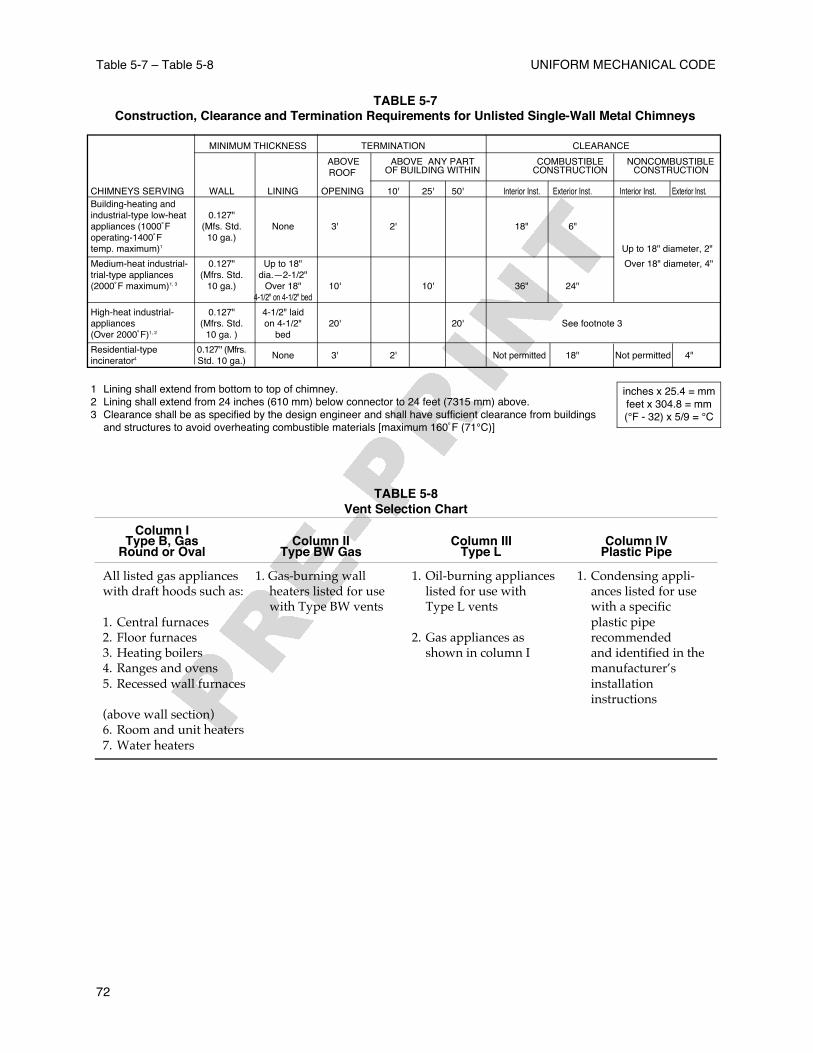
506.8 Protection from Physical Damage. D u c t sinstalled in locations where they are subject to physicaldamage shall be protected by suitable guards.506.9 Exhaust Outlets. Outlets for exhausts thatexceed 600˚F (315˚C) shall be in accordance withTable 5-7.
The termination point for exhaust ductsdischarging to the atmosphere shall be not less thanthe following:
5 0 6 . 9 . 1 Ducts conveying explosive or
EXHAUST SYSTEMS Table 5-2 – 506.9
49
TABLE 5-2Reduction of Duct Clearance with Specified Forms of Protection
Clearance reduction applied to and covering all combustile surfaces Minimum Allowable Reduction in Clearance (%)with the distance specified as required clearance with no protectionin 506.7.2
Form of Protection As Wall Protector As Ceiling Protector
(a) 3-1/2 in. (90 mm) thick masonry wall without ventilated airspace 33 ––(b) 1/2 in. (13 mm) thick noncombustile insulation board over 1 in. 50 33
(25.4 mm) glass fiber or mineral wool batts without ventilated airspace(c) 0.024 in. (0.61 mm) (No. 24 gage) sheet metal over 1 in. (25.4 mm) glass 66 66
fiber or mineral wool batts reinforced with wire, or equivalent, on rear facewith at least a 1 in. (25.4 mm) air gap
(d) 3-1/2 in (90 mm) thick masonry wall with at least a 1 in (25.4 mm) air gap 66 ––(e) 0.024 in. (0.61 mm) (No. 24 gage) sheet metal with at least a 1 in. (25.4 mm) 66 50
air gap(f) 1/2 in. (13 mm) thick noncombustible insulation board with at least a 1 in. 66 50
(25.4 mm) air gap(g) 0.024 in. (0.61mm) (No. 24 gage) sheet metal with ventilated airspace over 66 50
0.024 in. (0.61 mm) (No. 24 gage) sheet metal with at least a 1 in (25.4 mm)air gap
(h) 1 in. (25.4 mm) glass fiber or mineral wool batts sandwiched between two 66 50sheets 0.024 in. (0.61 mm) (No. 24 gage) sheet metal with at least a 1 in.(25.4 mm) air gap
Extent of protection required to reduce clearances from ducts.
TABLE 5-3Reduction of Clearances with Specified Forms of Protection
Where the required clearance with no protection from appliance, vent connector, or single-wall metal pipe is:
36 in. 18 in. 12 in. 9 in. 6 in.Allowable Clearances with Specified Protection (in.)
Type of protection appliedto and covering all surfaces Use Col. 1 for clearances above appliance or horizontal connector. Use Col. 2 for of combustible material clearances from appliances, vertical connector, and single-wall metal pipe.within the distance specifiedas the required clearance Sides Sides Sides Sides Sideswith no protection and and and and and[See Figures 9-1(a) Above Rear Above Rear Above Rear Above Rear Above Rearthrough 9-1(c)] Col. 1 Col. 2 Col. 1 Col. 2 Col. 1 Col. 2 Col. 1 Col. 2 Col. 1 Col. 2
(1) 3-1/2 in. thick masonry -- 24 -- 12 -- 9 -- 6 -- 5wall without ventilated air-space(2) 1/2 in. insulation board 24 18 12 9 9 6 6 5 4 3over 1 in. glass fiber ormineral wool batts(3) 0.024 sheet metal over 18 12 9 6 6 4 5 3 3 31 in. glass fiber or mineralwool batts reinforced withwire on rear face withventilated airspace(4) 3-1/2 in. thick masonry -- 12 -- 6 -- 6 -- 6 -- 6wall with ventilated airspace(5) 0.024 sheet metal with 18 12 9 6 6 4 5 3 3 2ventilated airspace(6) 1/2 in. thick insulation 18 12 9 6 6 4 5 3 3 3board with ventilated air-space(7) 0.024 sheet metal with 18 12 9 6 6 4 5 3 3 3ventilated airspace over0.024 sheet metal withventilated airspace(8) 1 in. glass fiber or 18 12 9 6 6 4 5 3 3 3mineral wool battssandwiched between twosheets 0.024 sheet metalwith ventilated airspace
For SI units, 1 in. = 25.4 mm.Notes:1 Reduction of clearances from combustible materials shall not interfere with combustion air, draft hood clearance and relief, and accessibility ofservicing.2 All clearances shall be measured from the outer surface of the combustible material to the nearest point on the surface of the appliance, disregardingany intervening protection applied to the combustible material.3 Spacers and ties shall be of noncombustible material. No spacer or tie shall be used directly opposite the appliance or connector.4 Where all clearance reduction systems use a ventilated air space, adequate provision for air circulation shall be provided as described. [See Figures 9-1(a) through 9-1(c).]5 There shall be at least 1 in. (25 mm) between clearance reduction systems and combustible walls and ceilings for reduction systems using a ventilatedairspace.6 Where a wall protector is mounted on a single flat wall away from corners, it shall have a minimum 1 in. (25 mm) air gap. To provide adequate aircirculation, the bottom and top edges, or only the side and top edges, or all edges shall be left open.7 Mineral wool batts (blanket or board) shall have a minimum density of 8 lb./ft.3 (128 kg/m3) and a minimum melting point of 1500˚F (816˚C).8 Insulation material used as part of a clearance reduction system shall have a thermal conductivity of 1.0 Btu in./ft.2 /hr.-˚F (0.144 W/m-K) or less.9 There shall be at least 1 in. (25 mm) between the appliance and the protector. In no case shall the clearance between the appliance and the combustiblesurface be reduced below that allowed in Table 5-3.10 All clearances and thicknesses are minimum; larger clearances and thicknesses are acceptable.11 Listed single-wall connectors shall be installed in accordance with the terms of their listing and the manufacturer's instructions.
UNIFORM MECHANICAL CODE
50
Table 5-3
flammable vapors, fumes, or dusts: thirty(30) feet (9144 mm) from property line; ten(10) feet (3048 mm) from openings into thebuilding: six (6) feet (1829 mm) fromexterior walls or roofs; thirty (30) feet (9144mm) from combustible walls or openingsinto the building which are in the directionof the exhaust discharge; ten (10) feet (3048mm) above adjoining grade.5 0 6 . 9 . 2 Other product-conveying outlets:ten (10) feet (3048 mm) from property line;three (3) feet (914 mm) from exterior wall orroof; ten (10) feet (3048 mm) from openingsinto the building; ten (10) feet (3048 mm)above adjoining grade.
Part II – Commercial Hoods and KitchenVentilation
507.0 General Requirements.507.1 Cooking equipment used in processesproducing smoke or grease-laden vapors shall beequipped with an exhaust system that complies withall the equipment and performance requirements ofthis standard, and all such equipment andperformance shall be maintained per this standardduring all periods of operation of the cookingequipment. Specifically, the following equipmentshall be kept in good working condition:
(A) Cooking equipment(B) Hoods(C) Ducts (if applicable)(D) Fans(E) Fire suppression systems(F) Special effluent or energy control equipmentAll airflows shall be maintained. Maintenanceand repairs shall be performed on allcomponents at intervals necessary to maintainthese conditions. 507.1.1 All solid-fuel cooking equipment shallcomply with the requirements of Section 517.0.5 0 7 . 1 . 2 Multiple-tenancy applications shallrequire the concerted cooperation of design,installation, operation, and maintenanceresponsibilities by tenants and by the buildingowner.5 0 7 . 1 . 3 All interior surfaces of the exhaustsystem shall be reasonably accessible forcleaning and inspection purposes.5 0 7 . 1 . 4 Cooking equipment used in fixed,mobile, or temporary concessions, such as
trucks, buses, trailers, pavilions, tents, or anyform of roofed enclosure, shall comply with thisstandard unless all or part of the installation isexempted by the Authority Having Jurisdiction.
507.2 Clearance.507.2.1 Except where enclosures are required,hoods, grease removal devices, exhaust fans,and ducts shall have a clearance of at least 18 in.(457.2 mm) to combustible material, 3 in. (76.2mm) to limited-combustible material, and 0 in. (0mm) to noncombustible material.
Exception No. 1: Where the hood, duct, orgrease removal device is listed for lesserclearances.Exception No. 2: Reduced clearance tocombustible material if the combustiblematerial is protected as follows:(a) 0.013 in. (0.33 mm) (no. 28 gage) sheet
metal spaced out 1 in. (25.4 mm) onn o n c o m b u s t i b l e spacers shall have 9 in.(228.6 mm) clearance to combustiblematerial.
(b) 0.027 in. (0.69 mm) (No. 22 gage) sheet metal on 1 in. (25.4 mm) mineral woolbatts or ceramic fiber blanket reinforced with wire mesh or equivalent spaced out1 in. (25.4 mm) on noncombustible spacers shall have 3-in. (76.2 mm) clearance to combustible material.
Exception No. 3: Reduced clearance tolimited-combustible materials to zeroclearance where protected by metal lath andplaster, ceramic tile, quarry tile, othernoncombustible materials or assembly ofnoncombustible materials, or materials andproducts that are listed for the purpose ofreducing clearance and are acceptable to theAuthority Having Jurisdiction. The listedmaterials shall be installed in accordancewith the conditions of the listing and themanufacturer's instructions and shall beacceptable to the Authority HavingJurisdiction.507.2.1.1 Measures shall be taken toprevent physical damage to any material orproduct used for the purpose of reducingclearances. In the event of damage, thematerial or product shall be repaired andrestored to meet its intended listing orclearance requirements and shall beacceptable to the Authority HavingJurisdiction. In the event of a fire within akitchen exhaust system, the duct and itsenclosure (rated shaft, factory-built greaseduct enclosure, or field-applied grease duct
EXHAUST SYSTEMS 506.9 – 507.2
51
enclosure) shall be inspected by qualifiedpersonnel to determine whether the ductand protection method are structurallysound, capable of maintaining their fireprotection function, and suitable forcontinued operation.
507.2.2 The protection methods for ducts toreduce clearance shall be applied to thecombustible or limited-combustible construction,not to the duct itself.
Exception: Field-applied grease ductenclosures and factory-built grease ductenclosures.
507.2.3 Field-applied grease duct enclosuresand factory-built grease duct enclosures shalldemonstrate that they provide sufficientmechanical and structural integrity, resiliency,and stability when subjected to expectedbuilding environmental conditions, ductmovement under general operating conditions,and duct movement due to fire conditions.Measures shall be taken to prevent physicaldamage to any material or product used for thepurpose of reducing clearances.
Exception: When the duct is protected witha field-applied grease duct enclosure orfactory-built grease duct enclosure.5 0 7 . 2 . 3 . 1 The specifications of material,gauge, and construction of the duct used inthe testing and listing of field applied greaseduct enclosures and factory-built greaseduct enclosures shall be included asminimum requirements in their listing andinstallation documentation.507.2.3.2 The following clearance optionsfor which field-applied grease ductenclosures and factory-built grease ductenclosures have been successfully evaluatedshall be clearly identified in their listing andinstallation documentation and on theirlabels:(A) Open combustible clearance atmanufacturer’s requested dimensions.(B) Closed combustible clearance atmanufacturer’s requested dimensions, withor without specified ventilation.(C) Rated shaft clearance at manufacturer’srequested dimensions, with or withoutspecified ventilation.
507.2.4 A duct shall be permitted to contactnoncombustible floors, interior walls, and othernoncombustible structures or supports, but itshall not be in contact for more than 50 percentof its surface area per each lineal foot of contactlength. Where such direct contact is made, the
duct shall be protected from corrosion due tothis contact.
Exception: When the duct is protected witha material or product listed for the purposeof reducing clearance to zero.
5 0 7 . 2 . 5 Clearances between the duct andinterior surfaces of enclosures shall meet therequirements of Section 507.2.
5 0 7 . 3 A drawing(s) of the exhaust systeminstallation along with a copy of operatinginstructions for subassemblies and components usedin the exhaust system, including electricalschematics, shall be available on the premises.5 0 7 . 4 If required by the Authority HavingJurisdiction, notification in writing shall be given ofany alteration, replacement, or relocation of anyexhaust or extinguishing system or part thereof orcooking equipment. Satisfaction shall be provided tothe Authority Having Jurisdiction that the completeexhaust system as addressed in this standard isinstalled and operable in accordance with theapproved design and the manufacturer’s instructions.507.5 Alternative Methods. Nothing in thisstandard is intended to prevent the use of othermethods or devices, provided that sufficienttechnical data is submitted to the Authority HavingJurisdiction to demonstrate that the proposedmethod or device is equivalent in quality, strength,fire endurance, effectiveness, durability, and safetyto that prescribed by this standard.
508.0 Hoods.508.1 Where Required. Hoods shall be installed ator above all commercial-type deep fat fryers,broilers, fry grills, steam-jacketed kettles, hot-topranges, ovens, barbecues, rotisseries, dishwashingmachines and similar equipment which producecomparable amounts of steam, smoke, grease or heatin a food-processing establishment. For the purposeof this section, a food-processing establishment shallinclude any building or portion thereof used for theprocessing of food, but shall not include a dwellingunit.508.1.1 Construction. The hood or that portion of aprimary collection means designed for collectingcooking vapors and residues shall be constructed ofand be supported by steel not less than 0.043 in. (1.09mm) (No. 18 MSG) in thickness, stainless steel notless than 0.037 in. (0.94 mm) (No. 20 MSG) inthickness, or other approved material of equivalentstrength and fire and corrosion resistance.
Exceptions:(1) Listed exhaust hoods with or without
exhaust dampers.
UNIFORM MECHANICAL CODE
52
507.2 – 508.2
(2) Type II hoods shall be constructed of at least 0.024 inch (0.61 mm) (No. 24 gage) steel.Hoods constructed of copper shall be ofcopper sheets weighing at least twenty-four (24) ounces per square foot (7.32 kg/m2). Joints and seams shall be substantially tight.Solder shall not be used except for sealing a joint or seam.
All hoods shal l be secured in place bynoncombustible supports.508.2 All seams, joints, and penetrations of the hoodenclosure that direct and capture grease-ladenvapors and exhaust gases shall have a liquidtightcontinuous external weld to the hood’s loweroutermost perimeter. Internal hood joints, seams,filter support frames, and appendages attachedinside the hood need not be welded but shall besealed or otherwise made greasetight.
Exception No. 1: Penetrations shall be permittedto be sealed by devices that are listed for suchuse and whose presence does not detract fromthe hood's or duct's structural integrity.Exception No. 2: Eyebrow-type hoods over gasor electric ovens shall be permitted to have a ductconstructed as in Section 510.0 from the ovenflue(s) connected to the hood canopy upstream ofthe exhaust plenum as shown in Figure 5-1. Theduct shall be connected to the hood with acontinuous weld or have a duct-to-ductconnection as shown in Figure 5-6(b) through (d).Exception No. 3: Seams, joints, and penetrationsof the hood shall be permitted to be internallywelded, provided that the weld is formedsmooth or ground smooth, so as to not trapgrease, and is readily cleanable.
Exception No. 4: Listed exhaust hoods with orwithout exhaust dampers.
5 0 8 . 3 Insulation materials other than electricalinsulation shall have a flame-spread rating of 25 orless when tested in accordance with UL 723,Standard for Test for Surface Burning Characteristicsof Building Materials. Adhesives or cements used inthe installation of insulating materials shall complywith the preceding requirements when tested withthe specific insulating material.508.4 Hood Size. Hoods shall be sized according tothe following calculations and configured to providefor the capture and removal of grease-laden vapors.(See Section 511.2.2.)
508.4.1 Canopy Size and Location. F o rcanopy-type commercial cooking hoods, theinside edge thereof shall overhang or extend ahorizontal distance of not less than six (6) inches(152 mm) beyond the edge of the cookingsurface on all open sides, and the verticaldistance between the lip of the hood and thecooking surface shall not exceed four (4) feet(1219 mm).
E x c e p t i o n : Listed exhaust hoods are to beinstalled in accordance with the terms oftheir listings and manufacturer’s installationinstructions.508.4.1.1 Capacity of Hoods. C a n o p y - t y p ecommercial cooking hoods shall exhaustthrough the hood a minimum quantity of airdetermined by application of the followingf o r m u l a s :
WHERE:A = the horizontal surface area of the hood, in square
feet (m2) .P = that part of the perimeter of the hood that is open, in
feet (mm).D = distance in feet (mm) between the lower lip of
the hood and the cooking surface.Q = quantity of air, in cubic feet per minute (L/s).
When cooking equipment is installed back to backand is covered by a common island-type hood, theairflow required may be calculated using theformula for three sides exposed. Type II hoodairflow requirements shall be in accordance with therequirements for low-temperature appliance hoods.
5 0 8 . 4 . 1 . 2 The minimum airflow for solid-fuel cooking equipment, grease-burning
EXHAUST SYSTEMS 508.2 – 508.4
53
FIGURE 5-1 Typical Section of Eyebrow-TypeHood.
charbroilers, and undefined equipment shallbe:
Number of Exposed Sides Formula4 (island or central hood) Q = 300A3 or less Q = 200AAlternate formula Q = 100PD
5 0 8 . 4 . 1 . 3 Type I hoods when the cookingequipment includes high-temperatureappliances such as deep-fat fryers:
Number of Exposed Sides Formula4 (island or central hood) Q = 150A3 or less Q = 100AAlternate formula Q = 100PD
508.4.1.4 Type I hoods where the cookingequipment includes medium-temperatureappliances such as rotisseries, grills andranges:
Number of Exposed Sides Formula4 (island or central hood) Q = 100A3 or less Q = 75AAlternate formula Q = 50PD
508.4.1.5 Type I hoods where the cookingequipment includes low-temperatureappliances such as medium-to-low-temperature ranges, roasters, roastingovens, pastry ovens, and equipmentapproved for use under a Type II hood, suchas pizza ovens:
Number of Exposed Sides Formula4 (island or central hood) Q = 75A3 or less Q = 50AAlternate formula Q = 50PD
Exception: Listed exhaust hoods are to beinstalled in accordance with the terms of theirlisting and the manufacturer’s installationi n s t r u c t i o n s .
508.4.2 Capacity for Noncanopy Hoods.In addition to all other requirements forhoods specified in this section, the volumeof air exhausting through a noncanopy-typehood to the duct system shall be not lessthan 300 cubic feet per minute per lineal foot(465 L/s per m) of cooking equipment.Listed noncanopy exhaust hoods and filtersshall be sized and installed in accordancewith the terms of their listing and the
manufacturer’s installation instructions.Exception: Listed hood assembliesdesigned and installed specifically for theintended use.
508.5 Exhaust Hood Assemblies with IntegratedSupply-Air Plenums.The construction and size of these hoods shallcomply with the requirements of Sections 508.1 and508.4.
508.5.1 The construction of the outer shell orthe inner exhaust shell shall comply with Section508.1. If the outer shell is welded, the inner shellshall be of greasetight construction.508.5.2 A fire-actuated damper shall beinstalled in the supply air plenum at each pointwhere a supply air duct inlet or a supply airoutlet penetrates the continuously welded shellof the assembly. The damper shall be listed forsuch use or be part of a listed exhaust hood withor without exhaust damper. The actuationdevice shall have a maximum temperaturerating of 286°F (141°C). Supply-air plenums thatdischarge air from the face rather than from thebottom or into the exhaust hood and that areisolated from the exhaust hood by thecontinuously welded shell extending to thelower outermost perimeter of the entire hoodassembly shall not require a fire-actuateddamper.
508.6 Listed Hood Assemblies . Listed hoodassemblies shall be installed in accordance with theterms of their listing and the manufacturer’sinstructions.508.7 Solid-Fuel Hood Assemblies. Where solid-fuel cooking equipment is to be used, the solid-fuelhood assembly shall comply with Section 517.0.508.8 Exhaust Outlets. An exhaust outlet within anunlisted hood shall be located so as to optimize thecapture of particulate matter. Each outlet shall servenot more than a twelve (12) foot (3658 mm) section ofan unlisted hood.
509.0 Grease Removal Devices in Hoods.509.1 Grease Removal Devices. Listed greasefilters, baffles, or other approved grease removaldevices for use with commercial cooking equipmentshall be provided. Listed grease filters shall be testedin accordance with UL 1046, Grease Filters forExhaust Ducts. Mesh filters shall not be used.509.2 Installation.
5 0 9 . 2 . 1 The distance between the greaseremoval device and the cooking surface shall beas great as possible but not less than 18 in. (457.2mm). Where grease removal devices are used in
UNIFORM MECHANICAL CODE
54
508.4 – 509.2
conjunction with charcoal or charcoal-typebroilers, including gas or electrically heatedcharbroilers, a minimum vertical distance of 4 ft.(1.22 m) shall be maintained between the loweredge of the grease removal device and thecooking surface.
Exception No. 1: Grease removal devicessupplied as part of listed hood assembliesshall be installed in accordance with theterms of the listing and the manufacturer’sinstructions.Exception No. 2: For cooking equipmentwithout exposed flame and where fluegases bypass grease removal devices, theminimum vertical distance shall bepermitted to be reduced to not less than 6in. (152.4 mm).
509.2.2 Grease removal devices shall beprotected from combustion gas outlets and fromdirect flame impingement occurring duringnormal operation of cooking appliancesproducing high flue gas temperatures, such asdeep-fat fryers or upright or high broilers(salamander broilers), where the distancebetween the grease removal device and theappliance flue outlet (heat source) is less than 18in. (457.2 mm). This protection shall bepermitted to be accomplished by the installationof a steel or stainless steel baffle plate betweenthe heat source and the grease removal device.The baffle plate shall be sized and located so thatflames or combustion gases shall travel adistance not less than 18 in. (457.2 mm) from theheat source to the grease removal device. Thebaffle shall be located not less than 6 in. (152.4mm) from the grease removal devices.509.2.3 Grease filters shall be listed andconstructed of steel or listed equivalent materialand shall be of rigid construction that will notdistort or crush under normal operation,handling, and cleaning conditions. Filters shallbe tight fitting and firmly held in place.5 0 9 . 2 . 4 Filters shall be easily accessible andremovable for cleaning.509.2.5 Filters shall be installed at an angle notless than 45 degrees from the horizontal.509.2.6 Filters shall be equipped with a driptray beneath their lower edges. The tray shall bekept to the minimum size needed to collectgrease and shall be pitched to drain into anenclosed metal container having a capacity notexceeding 1 gal. (3.785 L).509.2.7 Grease filters that require a specificorientation to drain grease shall be clearly sodesignated, or the hood shall be constructed so
that filters cannot be installed in the wrongorientation.
509.3 Solid-Fuel Grease Removal Devices.Where solid-fuel cooking equipment is providedwith grease removal devices, these devices shallcomply with Section 517.0.
510.0 Exhaust Duct Systems.510.1 General.
510.1.1 Ducts shall not pass through fire wallsor fire partitions.510.1.2 All ducts shall lead as directly as ispracticable to the exterior of the building, so asnot to unduly increase any fire hazard.5 1 0 . 1 . 3 Duct systems shall not beinterconnected with any other buildingventilation or exhaust system.510.1.4 All ducts shall be installed withoutforming dips or traps that might collect residues.In manifold (common duct) systems, the lowestend of the main duct shall be connected flush onthe bottom with the branch duct. Duct systemsserving a Type I hood shall be so constructedand installed that grease cannot becomepocketed in any portion thereof, and the systemshall slope not less than 1/4 inch per lineal foot(21 mm/m) toward the hood or toward anapproved grease reservoir. Where horizontalducts exceed seventy-five (75) feet (22860 mm) inlength, the slope shall be not less than one (1)inch per lineal foot (83 mm/m).510.1.5 Openings required for accessibility shallcomply with Section 510.3.5 1 0 . 1 . 6 A sign shall be placed on all accesspanels stating the following:
ACCESS PANEL––DO NOT OBSTRUCT5 1 0 . 1 . 7 Duct bracing and supports shall be ofnoncombustible material, securely attached tothe structure and designed to carry gravity andlateral loads within the stress limitations of theBuilding Code. Bolts, screws, rivets and othermechanical fasteners shall not penetrate ductwalls.510.1.8 Ducts, Non-Grease. Ducts andplenums serving Type II hoods shall beconstructed of rigid metallic materials as setforth in Chapter 6. Duct bracing and supportsshall comply with Chapter 6. Ducts subject topositive pressure shall be adequately sealed.
510.2 Clearance.510.2.1 Clearance between ducts andcombustible materials shall be provided in
EXHAUST SYSTEMS 509.2 – 510.3
55
accordance with the requirements of Section 507.2.510.2.2 Listed grease ducts shall be installed inaccordance with the terms of their listings andmanufacturers’ instructions.
510.3 Openings.510.3.1 Openings shall be provided at the sidesor at the top of the duct, whichever is moreaccessible, and at changes of direction. Openingsshall be protected by approved access panelsthat comply with Section 510.3.4.5.
Exception: Openings shall not be requiredin portions of the duct that are accessiblefrom the duct entry or discharge.
510.3.2 For hoods with dampers in the exhaustor supply collar, an access panel for cleaning andinspection shall be provided in the duct or thehood collar. This access panel shall be as close tothe hood as possible but shall not exceed 18 in.(457.2 mm).
Exception: Dampers that are accessiblefrom under the hood.
510.3.3 Exhaust fans with ductwork connectedto both sides shall have access for cleaning andinspection within 3 ft. (0.92 m) of each side of thefan.510.3.4 Openings shall conform with Sections510.3.4.1 through 510.3.4.5.
510.3.4.1 On horizontal ducts, at least one20 in. by 20 in. (508 mm by 508 mm)opening shall be provided for personnelentry. Horizontal ducting shall be securedsufficiently to allow for the weight ofpersonnel entry into the duct. Where anopening of this size is not possible, openingslarge enough to permit thorough cleaningshall be provided at 12 ft. (3.7 m) intervals.510.3.4.2 On nonlisted ductwork, the edgeof the opening shall be not less than 1-1/2in. (38.1 mm) from all outside edges of theduct or welded seams.5 1 0 . 3 . 4 . 3 On vertical ductwork wherepersonnel entry is possible, access shall beprovided at the top of the vertical riser toaccommodate descent. Where personnelentry is not possible, adequate access forcleaning shall be provided on each floor.510.3.4.4 Access panels shall be of thesame material and thickness as the duct(Section 510.5.1). Access panels shall havea gasket or sealant that is rated for 1500°F(815.6°C) and shall be greaset ight.
Fasteners , such as bolts, weld studs,latches, or wing nuts, used to secure theaccess panels shall be carbon steel orstainless steel and shall not penetrate ductw a l l s .
Exception: Listed grease duct accessdoor assemblies (access panels) shall beinstalled in accordance with their termsof the listings and the manufacturer'sinstructions.
510.3.4.5 Openings for installation,servicing, and inspection of listed fireprotection system devices and for ductcleaning shall be provided in ducts andenclosures and shall conform to therequirements of 510.3. Enclosure openingsrequired to reach access panels in theductwork shall be large enough for theremoval of the access panel.
510.4 Listed Grease Ducts. Listed grease ductsshall be installed in accordance with the terms of thelisting and the manufacturer’s instructions.510.5 Other Grease Ducts. Other grease ductsshall comply with the requirements of this section.
510.5.1 Materials. Ducts shall be constructed ofand supported by carbon steel not less than0.054 in. (1.37 mm) (No. 16 MSG) in thickness orstainless steel not less than 0.043 in. (1.09 mm)(No. 18 MSG) in thickness.
UNIFORM MECHANICAL CODE
56
510.3 – Figure 5-2
F I G U R E 5-2 Permitted Duct-to-Hood CollarConnection.
Exception No. 1: Duct-to-hood collarconnections as shown in Figure 5-2 shallbe permitted.Exception No. 2: Penetrations shall bepermitted to be sealed by other listeddevices that are tested to be greasetightand are evaluated under the sameconditions of fire severity as the hood orenclosure of listed grease extractors andwhose presence does not detract fromthe hood's or duct's structural integrity.Exception No. 3: Internal welding shallbe permitted, provided the joint is
formed or ground smooth and is readilyaccessible for inspection.
510.5.2.2 Overlapping duct connections ofeither the telescoping or the bell type shallbe used for welded field joints, not butt-weld connections. The inside duct sectionshall always be uphill of the outside ductsection. The difference between insidedimensions of overlapping sections shall notexceed 1/4 in. (6.4 mm). The overlap shallnot exceed 2 in. (50.8 mm). (See Figure 5-3.)
510.6 Exterior Installations.510.6.1 The exterior portion of theductwork shall be vertical wherever possibleand shall be installed and adequatelysupported on the exterior of a building.Bolts, screws, rivets, and other mechanicalfasteners shall not penetrate duct walls.Clearance of any ducts shall comply withSection 507.2.510.6.2 All ducts shall be protected on theexterior by paint or other suitable weather-protective coating or shall be constructed ofnoncorrosive stainless steel. Ductworksubject to corrosion shall have minimalcontact with the building surface.
510.7 Interior Installations.5 1 0 . 7 . 1 In all buildings more than one story inheight, and in one-story buildings where the roof-ceiling assembly is required to have a fireresistance rating, the ducts shall be enclosed in acontinuous enclosure extending from the lowestfire-rated ceiling or floor above the hood, throughany concealed spaces, to or through the roof so asto maintain the integrity of the fire separationsrequired by the applicable building codeprovisions. The enclosure shall be sealed aroundthe duct at the point of penetration of the lowestfire-rated ceiling or floor above the hood in orderto maintain the fire resistance rating of theenclosure and shall be vented to the exterior of thebuilding through weather-protected openings.
Exception: The continuous enclosureprovisions shall not be required where a field-applied grease duct enclosure or a factory-built grease duct enclosure (see Section507.2.3) is protected with a listed duct-through-penetration protection systemequivalent to the fire resistance rating of theassembly being penetrated, and the materialsare installed in accordance with the conditionsof their listings and the manufacturers’
EXHAUST SYSTEMS 510.6 – 510.7
57
F I G U R E 5-3 Telescoping and Bell-Type DuctConnections.
instructions and are acceptable to theAuthority Having Jurisdiction.
5 1 0 . 7 . 2 The enclosure required in Section 510.7.1shall conform to Sections 510.7.2.1 through 510.7.2.3.
510.7.2.1 If the building is less than four storiesin height, the enclosure wall shall have a fireresistance rating of not less than 1 hour.510.7.2.2 If the building is four stories or morein height, the enclosure wall shall have a fireresistance rating of not less than 2 hours.5 1 0 . 7 . 2 . 3 Clearance from the duct or the exhaustfan to the interior surface of enclosures ofcombustible construction shall be not less than 18in. (457.2 mm), and clearance from the duct to theinterior surface of enclosures of noncombustibleor limited-combustible construction shall be notless than 6 in. (152.4 mm). Provisions forreducing clearances as described in Section 507.2are not applicable to enclosures.
Exception: Clearance from the outersurfaces of field-applied grease ductenclosures and factory-built grease ductenclosures to the interior surfaces ofconstruction installed around them shall bepermitted to be reduced where the field-applied grease duct enclosure materials andfactory-built grease duct enclosures areinstalled in accordance with the conditionsof their listings and manufacturers’instructions and are acceptable to theAuthority Having Jurisdiction.
510.7.3 For field-applied grease duct enclosuresand factory-built grease duct enclosures, thematerials and products shall conform to Sections510.7.3.1 through 510.7.3.3.
5 1 0 . 7 . 3 . 1 Field-applied grease ductenclosures and factory-built grease ductenclosures shall demonstrate that theyprovide sufficient mechanical and structuralintegrity, resiliency, and stability whensubjected to expected building environmentalconditions, duct movement under generaloperating conditions, and duct movementdue to interior and exterior fire conditions.5 1 0 . 7 . 3 . 2 Measures shall be taken toprevent physical damage to any covering orenclosure material. Any damage to thecovering or enclosure shall be repaired andthe covering or enclosure restored to meetits intended listing and fire-resistive ratingand to be acceptable to the AuthorityHaving Jurisdiction.510.7.3.3 In the event of a fire within a kitchenexhaust system, the duct, the enclosure, or the
covering directly applied to the duct shall beinspected by qualified personnel to determinewhether the duct, the enclosure, and thecovering directly applied to the duct arestructurally sound, capable of maintainingtheir fire protection functions, suitable forcontinued operation, and acceptable to theAuthority Having Jurisdiction.
510.7.4 For listed grease ducts, see Section 510.4.5 1 0 . 7 . 5 If openings in the enclosure walls areprovided, they shall be protected by approvedself-closing fire doors of proper rating. Firedoors shall be installed in accordance withNFPA 80, Standard for Fire Doors and FireWindows. Openings on other listed materials orproducts shall be clearly identified and labeledaccording to the terms of the listing and themanufacturer's instructions and shall beacceptable to the Authority Having Jurisdiction.The panels shall be readily accessible.5 1 0 . 7 . 6 Each duct system shall constitute anindividual system serving only exhaust hoods inone fire zone on one floor. Multiple ducts shallnot be permitted in a single enclosure unlessacceptable to the Authority Having Jurisdiction.
510.8 Termination of Exhaust System.510.8.1 The exhaust system shall terminate asfollows:(A) Outside the building with a fan or duct.(B) Through the roof, or to the roof from
outside, as in Section 510.8.2, or through a wall, as in Section 510.8.3.
510.8.2 Rooftop Terminations.5 1 0 . 8 . 2 . 1 Rooftop terminations shall bearranged with or provided with thefollowing:
(A) A minimum of 10 ft. (3.05 m) of clearancefrom the outlet to adjacent buildings,property lines, and air intakes. Where spacelimitations absolutely prevent a 10 ft. (3.05m) horizontal separation from an air intake,a vertical separation shall be permitted, withthe exhaust outlet being a minimum of 3 ft. (0.92 m) above any air intake located within10 ft (3.05 m) horizontally.
(B) The exhaust flow directed up and awayfrom the surface of the roof and a minimumof 40 in. (1.02 m) above the roof surface.
(C) The ability to drain grease out of any trapsor low points formed in the fan or duct nearthe termination of the system into a collection container that is noncombustible,closed, rainproof, structurally sound for the
UNIFORM MECHANICAL CODE
58
510.7 – 510.8
service to which it is applied, and will not sustain combustion. A grease collectiondevice that is applied to exhaust systemsshall not inhibit the performance of any fan.
Exception: Grease containers that areevaluated for equivalency with thepreceding requirements and listed assuch.
(D) A listed grease duct complying with Section510.4, or with ductwork complying withSection 510.5.
(E) A hinged upblast fan supplied with flexibleweatherproof electrical cable and service hold-open retainer to permit proper inspection and cleaning that is listed forcommercial cooking equipment, providedthe ductwork extends a minimum of 18 in. (457.2 mm) above the roof surface and thefan discharges a minimum of 40 in. (1.02 m)above the roof surface. (See Section 511.1.1.)
(F) Other approved fan, provided (1) it meetsthe requirements of Sections 510.8.2(C) and511.1.3 and (2) its discharge or its extendedduct discharge meets the requirements of Section 510.8.2(B).510.8.2.2 Listed flexible connectors may beused on exterior roof locations whenrequired for proper equipment vibrationisolation.510.8.2.3 Fans shall be provided with safeaccess and a work surface for inspection andcleaning.
510.8.3 Wall Terminations.510.8.3.1 Wall terminations shall bearranged with or provided with thefollowing properties:(A) Through a noncombustible wall with a
minimum of 10 ft. (3.05 m) of clearancefrom the outlet to adjacent buildings,property lines, grade level, combustibleconstruction, electrical equipment or lines, and the closest point of any air intake or operable door or window at orbelow the plane of the exhaust termination. The closest point of any airintake or operable door or windowabove the plane of the exhaust termination shall be a minimum of 10 ft.(3.05 m) distant, plus 0.25 ft. (0.076 m)for each 1 degree from horizontal, theangle of degree being measured from the center of the exhaust termination to the center of the air intake or operabledoor or window. (See Figure 5-4.)
Exception: A wall termination in asecured area can be at a lowerheight above grade if acceptable tothe Authority Having Jurisdiction.
(B) The exhaust flow directed perpendicularlyoutward from the wall face or upward.
(C) All the ductwork pitched to drain thegrease back into the hood(s), or with adrain provided to bring the grease backinto a container within the building or into a remote grease trap.
(D) A listed grease duct complying withSection 510.4, or other ducts complyingwith Section 510.5.
(E) An approved fan, provided it meets therequirements of Sections 510.8.3.1(C) and 511.1.1 or 511.1.3.
510.9 Solid-Fuel Duct Systems. Where solid-fuelcooking equipment is to be vented, the duct systemshall comply with Section 517.0.
511.0 Air Movement.511.1 Exhaust Fans for Commercial Cooking
EXHAUST SYSTEMS 510.8 – Figure 5-4
59
F I G U R E 5-4 Exhaust Termination Distance fromFresh Air Intake (FAI) or Operable Door orWindow.
UNIFORM MECHANICAL CODE
60
511.1 – Figure 5-6(b)
FIGURE 5-5 Upblast Fan Clearances.
FIGURE 5-6(a) Typical Section of Duct-to-FanConnection––Butt Joint Method.
F I G U R E 5-6(b) Typical Section of Duct-to-FanConnection––Overlapping Method.
Equipment.Where solid-fuel cooking equipment is to be vented,the duct system shall comply with Section 517.0.
511.1.1 Approved upblast fans with motorssurrounded by the airstream shall behinged,supplied with flexible weatherproofelectrical cable and service hold-open retainers,and listed for this use. (See Figure 5-5.)Installation shall conform to the requirements ofSection 510.8.511.1.2 In-Line Exhaust Fans.
5 1 1 . 1 . 2 . 1 In-line fans shall be of the typewith the motor located outside the airstreamand with belts and pulleys protected fromthe airstream by a greasetight housing.They shall be connected to the exhaust ductby flanges securely bolted as shown inFigure 5-6(a), or by a system specificallylisted for such use. Flexible connectors shallnot be used.511.1.2.2 If the design or positioning of thefan allows grease to be trapped, a draindirected to a readily accessible and visiblegrease receptacle, not exceeding 1 gal. (3.8 L),shall be provided. In-line exhaust fans shallbe located in an easily accessible area ofadequate size to allow for service or removal.If the duct system connected to the fan is inan enclosure, the space or room in which theexhaust fan is located shall have the same fireresistance rating as the enclosure.
511.1.3 Utility set exhaust fans, if installed at therooftop termination point, shall meet therequirements of Section 510.8.2.1(A) throughSection 510.8.2.2. If the fan is installed within thebuilding, it shall be located in an easily accessiblearea of adequate size to allow for service orremoval. If the duct system connected to the fan isin an enclosure, the space or room in which theexhaust fan is located shall have the same fireresistance rating as the enclosure. The fan shall beconnected to the exhaust duct by flanges securelybolted as shown in Figures 5-6(a) through 5-6(d)or by a system specifically listed for such use.Flexible connectors shall not be used. Exhaustfans shall have a drain directed to a readilyaccessible and visible grease receptacle not toexceed 1 gal. (3.8 L).511.1.4 Exhaust fan housings shall beconstructed of carbon steel not less than 0.054 in.(1.37 mm) (No. 16 MSG) in thickness or stainlesssteel not less than 0.043 in. (1.09 mm) (No. 18MSG) in thickness or, if listed, constructed inaccordance with the terms of the listing.5 1 1 . 1 . 5 Openings for cleaning, servicing, andinspection shall conform to the requirements of
Section 510.3.3 Clearances shall conform to therequirements of Sections 507.2, or 510.7.2.3 ifinstalled within an enclosure.511.1.6 All wiring and electrical equipmentshall comply with NFPA 70, National ElectricalCode.
511.2 Airflow.511.2.1 The air velocity through any duct shallbe not more than 2500 ft. (457.2 m) per minute.Exception: Transition duct sections shall bepermitted to be connected to hoods and exhaustfans that do not meet this velocity, provided thatthey do not exceed 3 ft. (0.92 m) in length and donot contain traps for grease.511.2.2 Exhaust-air volumes for hoods shall beof sufficient level to provide for capture andremoval of grease-laden cooking vapors. Testdata, performance acceptable to the AuthorityHaving Jurisdiction, or both, shall be provided, displayed, or both, upon request.
Exception: Lower exhaust-air volumes shallbe permitted during no-load cookingconditions, provided they are sufficient tocapture and remove flue gases and residualvapors from cooking equipment.
511.2.3 A hood exhaust fan(s) shall continue tooperate after the extinguishing system has beenactivated, unless fan shutdown is required by alisted component of the ventilation system or bythe design of the extinguishing system. It shallnot be required to restart the hood exhaust fanwhen the extinguishing system is activated if theexhaust fan and all cooking equipment servedby the fan had previously been shut down.
511.3 Replacement Air. Replacement air quantityshall be adequate to prevent negative pressures in thecommercial cooking area(s) from exceeding 0.02 in.water column (4.98 kPa).
Exceptions:(1) When its fire-extinguishing system
discharges, makeup air suppliedinternally to a hood shall be shut off.(2) Compensating hoods shall meet the
airflow requirements specified inSections 508.4.1.3 through 508.4.1.5. Compensating hoods shall extract at least twenty percent (20%) of their required exhaust airflow from thekitchen area.
511.4 Common Duct (Manifold) Systems. 511.4.1 Master kitchen exhaust ducts that servemultiple tenants shall include provision to bleedair from outdoors or from adjacent spaces intothe master exhaust duct where required tomaintain the necessary minimum air velocity inthe master exhaust duct. 511.4.2 This bleed-air duct shall connect to thetop or side of the master exhaust duct. 5 1 1 . 4 . 3 The bleed-air duct shall have a firedamper at least 12 in. (304.8 mm) from theexhaust duct connection. 511.4.4 The bleed-air duct shall have the sameconstruction and clearance requirements as themain exhaust duct from the connection to theexhaust duct to at least 12 in. (304.8 mm) on bothsides of the fire damper. 511.4.5 Each bleed air duct shall have a meansof adjusting (e.g., using volume dampers) thebleed-air quantity. 5 1 1 . 4 . 6 Such means shall be installed inbetween the fire damper and the source of bleedair.511.4.7 A bleed air duct shall not be used for
EXHAUST SYSTEMS Figure 5-6(c) – 512.2
61
F I G U R E 5-6(c) Typical Section of Duct-to-FanConnection––Sealant Method.
F I G U R E 5-6(d) Typical Section of Duct-to-FanConnection––Direct to Fan Inlet Cone Method.
the exhaust of grease-laden vapors and shall beso labeled. 511.4.8 Unused tenant exhaust connections tothe master exhaust duct that are not used asbleed air connections shall be disconnected andsealed at the main duct.
511.5 Solid-Fuel Air Movement Requirements.Where solid-fuel cooking equipment is used, exhaustand replacement air also shall comply with Section 517.0.
512.0 Auxiliary Equipment.512.1 Dampers. Dampers shall not be installed inexhaust ducts or exhaust duct systems.
Exception: Where specifically listed for such useor where required as part of a listed or approveddevice or system.
512.2 Electrical Equipment.512.2.1 Wiring systems of any type shall not beinstalled in ducts.512.2.2 Motors, lights, and other electricaldevices shall not be installed in ducts or hoodsor located in the path of travel of exhaustproducts.
Exception: Where specifically approved forsuch use.
512.2.3 Lighting units in hoods shall be listedfor use over commercial cooking appliancesand installed in accordance with the terms oftheir listing.5 1 2 . 2 . 4 Lighting units on hoods shall not belocated in concealed spaces.
Exceptions:(1) Where part of a listed exhaust hood.(2) Where specifically listed for such useand installed in accordance with the termsof the listing.
5 1 2 . 2 . 5 All electrical equipment shall be installedin accordance with NFPA 70, National ElectricalCode, with due regard to the effects of heat,vapor, and grease on the equipment.
512.3 Other Equipment.512.3.1 Fume incinerators, thermal recoveryunits, air pollution control devices, or otherdevices shall be permitted to be installed inducts or hoods or located in the path of travel ofexhaust products where specifically approvedfor such use. Downgrading other parts of theexhaust system due to the installation of theseapproved devices, whether listed or not, shallnot be allowed.5 1 2 . 3 . 2 Any equipment, listed or otherwise,
that provides secondary filtration or airpollution control and that is installed in the pathof travel of exhaust products shall be providedwith an approved automatic fire-extinguishingsystem for the protection of the componentsections of the equipment and shall includeprotection of the ductwork downstream of theequipment, whether or not the equipment isprovided with a damper. If the equipment canbe a source of ignition, it shall be provided withappropriate detection to operate the fire-extinguishing system.5 1 2 . 3 . 3 Where a cooking exhaust systememploys an air pollution control device thatrecirculates air into the building, the provisionsof Section 516.0 shall apply.
512.4 Solid-Fuel Auxiliary Equipment. Where solid-fuel cooking comprises any part of a cooking operation,additional provisions and equipment as described inSection 517.0 shall be used where required.
513.0 Fire-Extinguishing Equipment.513.1 General Requirements.
5 1 3 . 1 . 1 Fire-extinguishing equipment for theprotection of grease removal devices, hoodexhaust plenums, and exhaust duct systemsshall be provided.5 1 3 . 1 . 2 Cooking equipment that producesgrease-laden vapors (such as, but not limited to,deep-fat fryers, ranges, griddles, broilers, woks,tilting skillets, and braising pans) shall beprotected by fire-extinguishing equipment.
513.2 Types of Equipment.5 1 3 . 2 . 1 Fire-extinguishing equipment shallinclude both automatic fire-extinguishingsystems as primary protection and portable fireextinguishers as secondary backup.
5 1 3 . 2 . 1 . 1 A placard identifying the use ofthe extinguisher as a secondary backupmeans to the automatic fire suppressionsystem shall be conspicuously placed neareach portable fire extinguisher in thecooking area.
513.2.2 Automatic fire-extinguishing systemsshall comply with standard UL 300, Fire Testingof Fire Extinguishing Systems for Protection ofRestaurant Cooking Areas, or other equivalentstandards and shall be installed in accordancewith their listings.
Exception: Automatic fire-extinguishingequipment provided as part of listedrecirculating systems complying withstandard UL 197, Standard for Safety—
UNIFORM MECHANICAL CODE
62
512.2 – 513.2
Commercial Electric Cooking Appliances.5 1 3 . 2 . 2 . 1 Automatic fire-extinguishingsystems shall be installed in accordance withthe terms of their listing, the manufacturer’sinstructions, and the following standardswhere applicable.(A) NFPA 12, Standard on Carbon Dioxide
Extinguishing Systems.(B) NFPA 13, Standard for the Installation
of Sprinkler Systems.(C) NFPA 17, Standard for Dry Chemical
Extinguishing Systems.(D) NFPA 17A, Standard for Wet Chemical
Extinguishing Systems.5 1 3 . 2 . 3 Grease removal devices, hood exhaustplenums, and exhaust ducts requiring protectionin accordance with Section 513.1.1 shall bepermitted to be protected by a listed fixed bafflehood containing a constant or fire-actuatedwater-wash system that is listed to extinguish afire in the grease removal devices, hood exhaustplenums, and exhaust ducts. Each such area notprovided with a listed water-wash extinguishingsystem shall be provided with an appropriatefire suppression system listed for the purpose.
5 1 3 . 2 . 3 . 1 The water for listed, fixed bafflehood assemblies shall be permitted to besupplied from the domestic water supplywhen the minimum water pressure andflow are provided in accordance with theterms of the listing. The water supply shallbe monitored by an annunciated low-water-pressure switch.513.2.3.2 The water wash in the fixed bafflehood shall be activated by the cookingequipment extinguishing system.
513.3 Simultaneous Operation. F i x e d - p i p eextinguishing systems in a single hazard area shallbe arranged for simultaneous automatic operationupon actuation of any one of the systems.
Exception No. 1: Where the fixed-pipeextinguishing system is an automatic sprinklersystem.Exception No. 2: A dry or wet chemical systemshall be permitted to be used to protect commonexhaust ductwork by one of the methodsspecified in NFPA 17, Standard for DryChemical Extinguishing Systems, or NFPA 17A,Standard for Wet Chemical ExtinguishingSystems, in lieu of simultaneous automaticoperation.
513.4 Fuel Shutoff.
513.4.1 Upon activation of any fire-extinguishing system for a cooking operation, allsources of fuel and electric power that produceheat to all equipment requiring protection bythat system shall automatically shut off.
5 1 3 . 4 . 2 Any gas appliance not requiringprotection, but located under the sameventilating equipment, shall also automaticallyshut off upon activation of any extinguishings y s t e m .5 1 3 . 4 . 3 Shutoff devices shall require manualreset.
513.5 Manual Activation.513.5.1 A readily accessible means for manualactivation shall be located between 42 in. and 60in. (1067 mm and 1524 mm) above the floor,located in a path of exit or egress, and clearlyidentify the hazard protected. The automatic andmanual means of system activation external to thecontrol head or releasing device shall be separateand independent of each other so that failure ofone will not impair the operation of the other.
Exceptions:(1) The manual means of system activation
shall be permitted to be common withthe automatic means if the manual activation device is located between the control head or releasing device and thefirst fusible link.
(2) An automatic sprinkler system.513.5.2 The means for manual actuator(s) shallbe mechanical and shall not rely on electricalpower for actuation.
E x c e p t i o n : Electrical power shall bepermitted to be used for manual activation ifa standby power supply is provided or ifsupervision is provided as per 513.7.1.
513.6 System Annunciation.513.6.1 Upon activation of an automatic fire-extinguishing system, an audible alarm or visualindicator shall be provided to show that thesystem has activated.513.6.2 Where a fire alarm signaling system isserving the occupancy where the extinguishingsystem is located, the activation of the automaticfire-extinguishing system shall activate the firealarm signaling system.
513.7 System Supervision.
EXHAUST SYSTEMS 513.2 – 513.9
63
513.7.1 Where electrical power is required tooperate the automatic fire-extinguishing system,it shall be monitored by a supervisory alarm,with a standby power supply provided.
Exceptions: (1) Where automatic fire-extinguishing
systems include automatic mechanicaldetection and actuation as a backup detection system.
(2) Where fire-extinguishing systems are interconnected or interlocked with thecooking equipment power sources so that if the fire-extinguishing system becomes inoperable due to power failure, all sourcesof fuel or electric power that produce heat to all cooking equipment serviced by that hood shall automatically shut off.
513.8 Special Design and Application.513.8.1 Hoods containing automatic fire-extinguishing systems are protected areas;therefore, these hoods are not consideredobstructions to overhead sprinkler systems andshall not require floor coverage underneath.513.8.2 A single listed detection device shall bepermitted for more than one appliance wheninstalled in accordance with the terms of thelisting.
513.9 Review and Certification.513.9.1 Where required, complete drawings ofthe system installation, including the hood(s),exhaust duct(s), and appliances, along with theinterface of the fire-extinguishing systemdetectors, piping, nozzles, fuel shutoff devices,agent storage container(s), and manual actuationdevice(s), shall be p r o v i d e d . submitted to theAuthority Having Jurisdiction.5 1 3 . 9 . 2 Installation of systems shall beperformed only by persons properly trained andqualified to install the specific system beingprovided. The installer shall provide certificationto the Authority Having Jurisdiction that theinstallation is in agreement with the terms of thelisting and the manufacturer's instructionsand/or approved design.
513.10 Portable Fire Extinguishers.513.10.1 Portable fire extinguishers shall beinstalled in kitchen cooking areas in accordancewith NFPA 10, Standard for Portable FireExtinguishers. Such extinguishers shall use agentsthat saponify upon contact with hot grease, suchas sodium bicarbonate and potassium bicarbonatedry chemical and potassium carbonate solutions.Class B gas-type portables such as CO2 and halon
shall not be permitted in kitchen cooking areas.Manufacturer's recommendations shall bef o l l o w e d .
513.10.1.1 Portable fire extinguishers listedspecifically for use in the kitchen cookingareas shall also be permitted.
513.10.2 Other fire extinguishers in the kitchenarea shall be installed in accordance with NFPA10, Standard for Portable Fire Extinguishers.
513 .11 Solid-Fuel F ire -Ext inguishingE q u i p m e n t .Where solid-fuel cooking equipment is served by fire-extinguishing equipment, the provisions of Section517.0 shall apply.
514.0 Procedures for the Use and Maintenanceof Equipment.514.1 Operating Procedures.
514.1.1 Exhaust systems shall be operatedwhenever cooking equipment is turned on.5 1 4 . 1 . 2 Filter-equipped exhaust systems shallnot be operated with filters removed.514.1.3 Openings provided for replacing airexhausted through ventilating equipment shallnot be restricted by covers, dampers, or anyother means that would reduce the operatingefficiency of the exhaust system.514.1.4 Instructions for manually operating thefire-extinguishing system shall be postedconspicuously in the kitchen and shall bereviewed periodically with employees by themanagement.514.1.5 Listed exhaust hoods shall be operatedin accordance with the terms of their listings andthe manufacturer's instructions.5 1 4 . 1 . 6 Cooking equipment shall not beoperated while its fire-extinguishing system orexhaust system is nonoperational or otherwiseimpaired.
514.2 Inspection. An inspection and servicing ofthe fire-extinguishing system and listed exhausthoods containing a constant or fire-actuated watersystem shall be made at least every six months byproperly trained and qualified persons.
514.2.1 All actuation components, includingremote manual pull stations, mechanical orelectrical devices, detectors, actuators, and fire-actuated dampers, shall be checked for properoperation during the inspection in accordancewith the manufacturer's listed procedures. Inaddition to these requirements, the specific
UNIFORM MECHANICAL CODE
64
513.9 – 514.3
inspection requirements of the applicable NFPAstandard shall also be followed.514.2.2 Fusible links (including fusible links onfire-actuated damper assemblies) and automaticsprinkler heads shall be replaced at leastannually, or more frequently if necessary, toensure proper operation of the system. Otherdetection devices shall be serviced or replaced inaccordance with the manufacturer'srecommendations.
E x c e p t i o n : Where automatic bulb-typesprinklers or spray nozzles are used andannual examination shows no buildup ofgrease or other material on the sprinkler orspray nozzles.
514.2.3 If required, certificates of inspectionand maintenance shall be p r o v i d e d . f o r w a r d e dto the Authority Having Jurisdiction.
514.3 Cleaning.5 1 4 . 3 . 1 Hoods, grease removal devices, fans,ducts, and other appurtenances shall be cleanedto bare metal or the original factory coating a tfrequent intervals prior to surfaces becomingheavily contaminated with grease or oily sludge.After the exhaust system is cleaned to barem e t a l , it shall not be coated with powder orother substance. The entire exhaust system shallbe inspected by a properly trained, qualified,and certified company or person(s) acceptable tothe Authority Having Jurisdiction in accordancewith Table 5-4.
TABLE 5-4 Exhaust System Inspection Schedule
Type or Volume of Cooking FrequencyFrequencySystems serving solid-fuel cooking operations MonthlySystems serving high-volume cooking Quarterlyoperations such as 24-hour cooking, charbroiling, or wok cookingSystems serving moderate- Semiannuallyvolume cooking operationsSystems serving low-volume cooking Annuallyoperations, such as churches, day camps,seasonal businesses, or senior centers
514.3.1.1 Upon inspection, if found to becontaminated with deposits from grease-laden vapors, the entire exhaust system shall
be cleaned by a properly trained, qualified,and certified company or person(s)acceptable to the Authority HavingJurisdiction in accordance with Section 514.3.5 1 4 . 3 . 1 . 2 When a vent-cleaning service isused, a certificate showing date ofinspection or cleaning shall be maintainedon the premises. After cleaning iscompleted, the vent-cleaning contractorshall place or display within the kitchen areaa label indicating the date cleaned and thename of the servicing company. It shall alsoindicate areas not cleaned.
514.3.2 Flammable solvents or other flammablecleaning aids shall not be used.5 1 4 . 3 . 3 At the start of the cleaning process,electrical switches that could be activatedaccidentally shall be locked out.5 1 4 . 3 . 4 Components of the fire suppressionsystem shall not be rendered inoperable duringthe cleaning process.
E x c e p t i o n : Servicing by properly trainedand qualified persons in accordance withSection 514.2.
5 1 4 . 3 . 5 Care shall be taken not to apply cleaningchemicals on fusible links or other detectiondevices of the automatic extinguishing system.5 1 4 . 3 . 6 When cleaning procedures arecompleted, all electrical switches and systemcomponents shall be returned to an operablestate. All access panels (doors) and cover platesshall be replaced. Dampers and diffusers shall bepositioned for proper airflow.
514.4 Operation, Maintenance, and Inspection ofSolid Fuel Cooking Equipment.Where solid-fuel cooking equipment is used, thespecial provisions of Section 517.0 shall apply.
5 1 5 . 1 . 1 Cooking equipment shall be approvedbased on one of the following criteria:(A) Listings by a testing laboratory.(B) Test data acceptable to the Authority
Having Jurisdiction.515.1.2 Installation.
515.1.2.1 All listed appliances shall beinstalled in accordance with the terms oftheir listings and the manufacturer'sinstructions.515.1.2.2 Cooking appliances requiring
EXHAUST SYSTEMS Table 5-4 – 516.1
65
protection shall not be moved, modified, orrearranged without prior reevaluation of thefire-extinguishing system by the systeminstaller or servicing agent, unless otherwiseallowed by the design of the fire-extinguishing system.
Exception: Cooking appliances movedto perform maintenance and cleaningprovided the appliances are returned totheir original positioning prior tocooking operations, and anydisconnected fire-extinguishing systemnozzles attached to the appliances arereconnected in accordance with themanufacturer's listed design manual.
515.1.2.3 All deep-fat fryers shall beinstalled with at least a 16 in. (406.4 mm)space between the fryer and surface flamesfrom adjacent cooking equipment.
E x c e p t i o n : Where a steel or temperedglass baffleplate is installed at aminimum 8 in. (203 mm) in heightbetween the fryer and surface flames ofthe adjacent appliance.
515.2 Operating Controls. Deep-fat fryers shall beequipped with a separate high-limit control inaddition to the adjustable operating control(thermostat) to shut off fuel or energy when the fattemperature reaches 475°F (246°C) at 1 in. (25.4 mm)below the surface.
516.0 Recirculating Systems.516.1 General Requirements. R e c i r c u l a t i n gsystems containing or for use with appliances usedin processes producing smoke or grease-ladenvapors shall be equipped with componentscomplying with the following:
(A) The clearance requirements of Section 507.2.(B) A hood complying with the requirements of
Section 508.0.(C) Grease removal devices complying with
Section 509.0.(D) The air movement requirements of Sections
511.2.1 and 511.2.2.(E) Auxiliary equipment (such as particulate
and odor removal devices) complying with Section 512.0.
(F) Fire-extinguishing equipment complying with the requirements of Section 513.0.
E x c e p t i o n : References to ducts inSections 513.1.1 and 513.5.1.
(G) The use and maintenance requirements of 514.0.
(H) The minimum safety requirements of
Section 515.0.(I) All the requirements of this chapter.
516.2 Design Restrictions. All recirculatingsystems shall comply with Section 516.2.
516.2.1 Only gas- or electrically fueled cookingappliances shall be used. Gas-fueled appliancesshall not have the combustion flue outlet(s)directly connected to the recirculating system.Gas-fueled appliances shall have a minimum 18in. (457.2 mm) clearance from the flue outlet tothe filter inlet in accordance with Section 509.2.2and shall meet the installation requirements ofNFPA 54, National Fuel Gas Code, or NFPA 58,Liquefied Petroleum Gas Code.5 1 6 . 2 . 2 Recirculating systems shall be listedwith a testing laboratory. There shall be nosubstitution or exchange of cooking appliances,filter components, blower components, or fire-extinguishing system components that wouldviolate the listing of the appliance.516.2.3 A recirculating system shall usecooking equipment that exceeds that system'slabeled maximum limits for that type ofequipment, stated in maximum energy input,maximum cooking temperature, and maximumsquare area of cooking surface or cubic area ofcooking cavity. The listing label shall not showthe type(s) of cooking equipment tested and thepreceding maximum limits.516.2.4 A fire-actuated damper shall be installedat the exhaust outlet of the system. The dampershall be constructed of at least the same gauge asthe shell. The actuation device shall have amaximum temperature rating of 375°F (190°C).5 1 6 . 2 . 5 No electrical wiring shall be installedin the interior sections of the hood plenum thatmight become exposed to grease.
Exception: As permitted by NFPA 70,National Electrical Code.
5 1 6 . 2 . 6 The power supply of any electrostaticprecipitator (ESP) shall be of the "cold spark,"ferro-resonant type in that the voltage falls off asthe current draw of a short increases.5 1 6 . 2 . 7 Listing evaluation shall include thefollowing:
(A) Capture and containment of vapors atpublished and labeled airflows.
(B) Grease discharge at the exhaust outlet of the system not to exceed an average of 5 mg/m3 of exhausted air sampledfrom that equipment at maximum amount of product that is capable of being processed over a continuous 8-
UNIFORM MECHANICAL CODE
66
516.1 – 516.3
hour test per EPA Test Method 202, Determination of Condensable Par-ticulate Emissions for StationarySources, with the system operating at itsminimum listed airflow.
(C) Listing and labeling of clearance tocombustibles from all sides, top, andbottom.
(D) Electrical connection in the field in accordance with NFPA 70, National Electrical Code.
(E) Interlocks on all removable componentsthat lie in the path of airflow within theunit to ensure that they are in place during operation of the cookingappliance.
516.3 Interlocks. The recirculating system shall beprovided with interlocks of all critical componentsand operations as indicated in Sections 516.3.1through 516.3.4 such that, if any of these interlocksare interrupted, the cooking appliance shall not beable to operate.
516.3.1 All closure panels encompassingairflow sections shall have interlocks to ensurethe panels are in place and fully sealed.516.3.2 Each filter component (grease and odor)shall have an interlock to prove the componentis in place.5 1 6 . 3 . 3 Each ESP shall have a sensor to prove itsperformance is as designed, with no interruptionof the power to exceed 2 minutes. This sensorshall be a manual reset device or circuit.516.3.4 An airflow switch or transducer shall beprovided after the last filter component toensure that a minimum airflow is maintained.This device opens the interlock circuit when theairflow falls 25 percent below the system'snormal operating flow or 10 percent below itslisted minimum rating, whichever is lower. Thisswitch or transducer shall be a manual resetdevice or circuit.
516.4 Location and Application Restrictions. T h elocation of recirculating systems shall be approved bythe Authority Having Jurisdiction. Items to be reviewedin the fire risk assessment shall include, but not belimited to, life safety, combustibility of surroundings,proximity to air vents, and total fuel load.516.5 Additional Fire Safety Requirements.
516.5.1 In addition to the appliance nozzle(s), arecirculating system shall be listed with theappropriate fire protection for grease filters,grease filtration, odor filtration units, and
ductwork where applicable.516.5.2 In addition to any other fire-extinguishing system actuation device, thereshall be a fire-extinguishing system actuationdevice installed downstream of any ESP.516.5.3 The requirements of Section 513.6 shallalso apply to recirculating system locations.
516.6 Use and Maintenance.516.6.1 Automatic or manual covers on cookingappliances, especially fryers, shall not interferewith the application of the fire suppressionsystem.516.6.2 All filters shall be cleaned or replaced inaccordance with the manufacturer's instructions.516.6.3 All ESPs shall be cleaned a minimum ofonce per week following manufacturer'scleaning instructions.516.6.4 The entire hood plenum and the blowersection shall be cleaned a minimum of onceevery three months.516.6.5 Inspection and testing of the totaloperation and all safety interlocks in accordancewith the manufacturer's instructions shall beperformed by qualified service personnel aminimum of once every six months or morefrequently if required.
Exception: Fire-extinguishing equipmentshall be inspected in accordance withSection 514.2.
516.6.6 A signed and dated log of maintenanceas performed in accordance with Sections 516.6.4and 516.6.5 shall be available on the premises foruse by the Authority Having Jurisdiction.
517.0 Solid-Fuel Cooking Operations.517.1 Venting Application. Venting requirementsof solid-fuel cooking operations shall be determinedin accordance with Sections 517.1.1 through 517.1.6.
517.1.1 Where solid-fuel cooking equipment isrequired by the manufacturer to have a naturaldraft, the vent shall comply with Section 517.4.517.1.2 Where the solid-fuel cooking equipmenthas a self-contained top, is the only appliance tobe vented in an isolated space (except for a singlewater heater with its own separate vent), has aseparate makeup-air system, and is providedwith supply and return air (not supplied orreturned from other spaces), the system shallcomply with Sections 517.4 and 517.6.517.1.3 Where the solid-fuel cooking equipmentis located in a space with other vented
EXHAUST SYSTEMS 516.3 – 517.2
67
equipment, all vented equipment shall have anexhaust system interlocked with a makeup-airsystem for the space as per Section 517.6.5 1 7 . 1 . 4 Natural draft ventilation systems andpower-exhausted ventilation systems shallcomply with Sections 517.3, 517.4, and 517.6.517.1.5 Where a solid-fuel cooking applianceallows effluent to escape from the applianceopening, this opening shall be covered by a hoodand an exhaust system that meets therequirements of Sections 517.3, 517.4, and 517.6.517.1.6 Solid-fuel cooking operations shall havespark arresters to minimize the passage ofairborne sparks and embers into plenums andducts. Where the solid-fuel cooking operation isnot located under a hood, a spark arrester shallbe provided to minimize the passage of sparksand embers into flues and chimneys.
517.2 Location of Appliances.517.2.1 Every appliance shall be located withrespect to building construction and otherequipment so as to permit access to the appliance.517.2.2 Solid-fuel cooking appliances shall notbe installed in confined spaces. The space orroom shall be of ample size to permit adequatecirculation of heated air.
E x c e p t i o n : Solid-fuel cooking applianceslisted for installation in confined spacessuch as alcoves shall be installed inaccordance with the terms of the listing andthe manufacturer's instructions.
517.2.3 Solid-fuel cooking appliances shall notbe installed in any location where gasoline orany other flammable vapors or gases are likelyto be present.
517.3 Hoods for Solid-Fuel Cooking.517.3.1 Hoods shall be sized and located in amanner capable of capturing and containing allof the effluent discharging from the appliances.The hood and its exhaust system shall complywith the provisions of the code.517.3.2 All solid-fuel cooking equipmentserved by hood and duct systems shall beseparate from all other exhaust systems.
E x c e p t i o n : Cooking equipment not requiringautomatic fire-extinguishing equipment (asper the provisions of Section 510.0) shall bepermitted to be installed under a commonhood with solid-fuel cooking equipment thatis served by a duct system separate from allother exhaust systems.
517.4 Exhaust Systems for Solid-Fuel Cooking.
Where a hood is not required, in buildings where theduct system is three stories or less in height, a ductcomplying with Section 510.0 shall be provided.
517.4.1 If a hood is used, the duct system shallconform with the Section 510.0.517.4.2 A listed or approved grease duct s y s t e mshall be provided for solid-fuel cooking exhaustsystems that are four stories in height or greater.517.4.3 Where a hood is used, the duct systemshall conform with the requirements of Section510.0.517.4.4 Wall terminations of solid-fuel exhaustsystems shall be prohibited.
517.5 Grease Removal Devices for Solid-FuelC o o k i n g . Grease removal devices shall beconstructed of steel or stainless steel or be approvedfor solid-fuel cooking.
5 1 7 . 5 . 1 If airborne sparks and embers can begenerated by the solid-fuel cooking operation,spark arrester devices shall be used prior to thegrease removal device to minimize the entrance ofthese sparks and embers into the grease removaldevice and into the hood and duct system.517.5.2 Filters shall be a minimum of 4 ft. (1.2m) above the appliance cooking surface.
517.6 Air Movement for Solid-Fuel Cooking.Exhaust system requirements shall comply with theprovisions of the code for hooded operation or shallbe installed in accordance with the manufacturer'srecommendation for unhooded applications.
5 1 7 . 6 . 1 A replacement or makeup-air systemshall be provided to ensure a positive supply ofreplacement air at all times during cookingoperations.5 1 7 . 6 . 2 Makeup-air systems serving solid-fuelcooking operations shall be interlocked with theexhaust-air system and powered, if necessary, toprevent the space from attaining a negative pressurewhile the solid-fuel appliance is in operation.
517.7 Fire-Extinguishing Equipment for Solid-Fuel Cooking.
517.7.1 Approved fire-extinguishing equipmentshall be provided to protect all solid-fuel-burning cooking appliances that might be asource of ignition of grease in the hood, greaseremoval device, or duct.
Exception: If acceptable to the AuthorityHaving Jurisdiction, solid-fuel-burningcooking appliances constructed of solidmasonry or reinforced portland orrefractory cement concrete and vented inaccordance with NFPA 211, Standard forChimneys, Fireplaces, Vents, and Solid
UNIFORM MECHANICAL CODE
68
517.3 – 517.7
Fuel–Burning Appliances, Chapters 3 and 4,shall not require fixed automatic fire-extinguishing equipment.
517.7.2 Approved fire-extinguishing equipmentshall be provided for the protection of greaseremoval devices, hoods, and duct systems.
E x c e p t i o n : If acceptable to the AuthorityHaving Jurisdiction, solid -fuel-burningcooking appliances constructed of solidmasonry or reinforced portland or refractorycement concrete and vented in accordancewith NFPA 211, Standard for Chimneys,Fireplaces, Vents, and Solid Fuel–BurningAppliances, Chapters 3 and 4, shall notrequire automatic fire-extinguishingequipment.
517.7.3 Approved fire-extinguishingequipment for solid-fuel-burning cookingappliances, where required, shall comply withNFPA 211 and shall be comprised of water-based agents.517.7.4 Fire-extinguishing equipment shall berated and designed to extinguish solid-fuelcooking fires, in accordance with themanufacturer's recommendations. The fire-extinguishing equipment shall be of sufficient sizeto totally extinguish fire in the entire hazard areaand prevent reignition of the fuel.5 1 7 . 7 . 5 All solid-fuel appliances (whether ornot under a hood) with fireboxes of 5 ft.3 ( 0 . 1 4m3) volume or less shall at least have a 2-A-ratedwater-type or wet chemical fire extinguisher inaccordance with NFPA 10, Standard for PortableFire Extinguishers, in the immediate vicinity ofthe appliance. Two portable fire extinguishers ofat least 1-1/2 gal. (5.7 L) each and containingpotassium citrate, potassium acetate, orpotassium carbonate solutions shall bepermitted to be used instead of the one 2-A-rated portable fire extinguisher.517.7.6 Solid-fuel appliances with fireboxesexceeding 5 ft.3 (0.14 m3) shall be provided with afixed-water-pipe system with a hose in theimmediate vicinity of the appliance. The systemshall have a minimum operating pressure of 40 psi(275.8 kPa) and shall provide a minimum of 5 gpm. 517.7.7 Fire suppression for fuel storage areasshall comply with Section 517.9.517.7.8 In addition to the requirements ofSections 517.7.5 or 517.7.6, where any solid-fuelcooking appliance is also provided withauxiliary electric, gas, oil, or other fuel forignition or supplemental heat and the applianceis also served by any portion of a fire-
extinguishing system complying with Section513.0, such auxiliary fuel shall be shut off uponactuation of the fire-extinguishing system.
517.8 Other Safety Requirements.517.8.1 Metal-fabricated solid fuel cookingappliances shall be listed for the applicationwhere produced in practical quantities or shall beapproved by the Authority Having Jurisdiction.When listed, they shall be installed in accordancewith the terms of their listings and with theapplicable requirements of this standard.517.8.2 Site-built solid fuel cooking appliancesshall be submitted for approval to the AuthorityHaving Jurisdiction before being considered forinstallation. All units submitted to the AuthorityHaving Jurisdiction shall be installed, operated,and maintained in accordance with theapproved terms of the manufacturer'sinstructions and any additional r e q u i r e m e n t s setforth by the Authority Having Jurisdiction.517.8.3 Except for the spark arrester required inSection 517.1.6, there shall be no additionaldevices of any type in any portion of theappliance, flue pipe, and chimney of a naturaldraft solid fuel operation.5 1 7 . 8 . 4 No solid fuel cooking device of anytype shall be permitted for deep-fat fryinginvolving more than one quart of liquidshortening, nor shall any solid-fuel cookingdevice be permitted within 3 ft. (0.92 m) of anydeep-fat frying unit.
EXHAUST SYSTEMS
69
517.7 – 517.8
UNIFORM MECHANICAL CODE
70
Table 5-5
70
TABLE 5-5Minimum Sheet Metal Thickness for Round Ducts for Product-Conveying System Ducts
Reinf. Class 1Negative SpacingPressure (Inches) Up to 7" 8" to 11" 12" to 15" 16" to 19" 20" to 23" 24" to 35" 36" to 47" 48" to 59" 60"
TABLE 5-5 (Continued)Minimum Sheet Metal Thickness for Round Ducts for Product-Conveying System Ducts
Reinf. Class 3Negative SpacingPressure (Inches) Up to 7" 8" to 11" 12" to 15" 16" to 19" 20" to 23" 24" to 35" 36" to 47" 48" to 59" 60"12" to 15" 0 .033 (20 ga.) .033 (20 ga.) .055 (16 ga.) .068 (14 ga.) .097 (12 ga.) .097 (12 ga.)
Column IType B, Gas Column II Column III Column IV
Round or Oval Type BW Gas Type L Plastic Pipe
All listed gas applianceswith draft hoods such as:
1. Central furnaces2. Floor furnaces3. Heating boilers4. Ranges and ovens5. Recessed wall furnaces
(above wall section)6. Room and unit heaters7. Water heaters
1. Gas-burning wall heaters listed for use with Type BW vents
1. Oil-burning applianceslisted for use with Type L vents
2. Gas appliances as shown in column I
1. Condensing appli-ances listed for use with a specific plastic pipe recommended and identified in themanufacturer’s installation instructions
TABLE 5-7Construction, Clearance and Termination Requirements for Unlisted Single-Wall Metal Chimneys
MINIMUM THICKNESS TERMINATION CLEARANCEABOVE ABOVE ANY PART COMBUSTIBLE NONCOMBUSTIBLE ROOF OF BUILDING WITHIN CONSTRUCTION CONSTRUCTION
CHIMNEYS SERVING WALL LINING OPENING 10' 25' 50' Interior Inst. Exterior Inst. Interior Inst. Exterior Inst.Building-heating and industrial-type low-heat 0.127"appliances (1000˚F (Mfs. Std. None 3' 2' 18" 6"operating-1400˚F 10 ga.)temp. maximum)1 Up to 18" diameter, 2"Medium-heat industrial- 0.127" Up to 18" Over 18" diameter, 4"trial-type appliances (Mfrs. Std. dia.—2-1/2"(2000˚F maximum)1, 3 10 ga.) Over 18" 10' 10' 36" 24"
4-1/2" on 4-1/2" bedHigh-heat industrial- 0.127" 4-1/2" laidappliances (Mfrs. Std. on 4-1/2" 20' 20' See footnote 3(Over 2000˚F)1, 2 10 ga. ) bedResidential-type 0.127" (Mfrs. None 3' 2' Not permitted 18" Not permitted 4"incinerator4 Std. 10 ga.)
1 Lining shall extend from bottom to top of chimney.2 Lining shall extend from 24 inches (610 mm) below connector to 24 feet (7315 mm) above.3 Clearance shall be as specified by the design engineer and shall have sufficient clearance from buildings
and structures to avoid overheating combustible materials [maximum 160˚F (71°C)]
inches x 25.4 = mmfeet x 304.8 = mm(°F - 32) x 5/9 = °C