Turbulent Heat Transfer Performance of Internally Longitudinally Finned Tubes
M. Lin & Q.W. WangSchool of Energy and Power Engineering, Xi’an Jiaotong University, Xi’an, Shaanxi, China.
Abstract
Heat transfer performance of internally longitudinally fi nned tubes with blocked core-tube is investigated at turbulent fl ow under the conditions of uniform heat fl ux and constant wall temperature. First, the problem of the optimization for the ratio of core-tube outside diameter to outer-tube inside diameter (do/Di) is intro-duced. Then three lateral fi n profi les (S shape, Z shape, and V shape fi ns) and three internally longitudinal fi n patterns (interrupted wavy fi n, sinusoidal wavy fi n, and plain fi n) are compared to fi nd out a best fi n pattern for design, respectively. The results show that the Z-shaped fi nned tubes and sinusoidal wavy fi nned tubes have the best comprehensive performance, respectively. Moreover, the optimiza-tion for the ratio of core-tube outside diameter to outer-tube inside diameter (do/Di) is obtainable according to the benefi cial coeffi cient. Finally, the correlations of Nusselt number and friction factor are found with the Reynolds number and dimensionless fi n wave height and dimensionless wave distance.
Keywords: Blocked core-tube; heat transfer performance; internally longitudinally fi nned tube; periodic wavy channel; turbulent fl ow
1 Introduction
Tubes with internal longitudinal fi ns are used to enhance heat transfer by increasing its heat transfer surface area. They are widely employed in compact heat exchang-ers in recent years, such as the intercooler of multi-stage compressors. The knowledge of heat transfer enhancement mechanism is of course important for both design and operation of these kinds of heat exchangers.
Many experimental investigations and numerical simulation have been pre-sented for different kinds of internally longitudinally fi nned tubes [1–30]. It can be
seen that, almost all the aforementioned literature studied the plain fi n along the streamwise (longitudinal) direction in the tube. However, longitudinally wavy fi n is one of the popular fi n patterns to improve heat transfer such as in the plate-and-fi n heat exchangers. The wavy surface can change the fl ow direction of fl uid and cause better mixing. Hence, higher heat transfer performance can be expected compared with the plain fi n surfaces [31–51].
In this chapter, the problem of optimizing the heat transfer of blocked core-tube diameter in internally plain-fi nned tubes under the conditions of turbulent fl ow and both uniform wall temperature and imposed wall heat fl ux on the tube wall will be fi rstly introduced [52]. Afterward, lateral wavy fi n profi les of internally fi nned tube fi tted with identical numbers of fi ns, which are S shape, Z shape, and V shape fi ns, are investigated [53]. The comprehensive performances of the studied tubes are compared under three constraints: identical mass fl ow rate, identical pumping power, and identical pressure drop. The objective is to investigate the effect of lateral fi n profi le on friction factors and Nusselt numbers for blocked core-tube with internally longitudinal plain fi ns. Then, three different kinds of internally longitudinal fi n patterns (interrupted wavy fi n, sinusoidal wavy fi n, and plain fi n) are compared to fi nd out a best fi n pattern for design [54]. Finally, the correlations of heat transfer and pressure drop for the longitudinal wavy fi nned tube is obtainable with the Reynolds number and dimensionless fi n wave height and dimensionless wave distance [55].
2 Physical Model
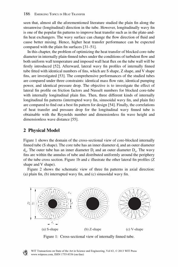
Figure 1 shows the domain of the cross-sectional view of core-blocked internally fi nned tube (S shape). The core tube has an inner diameter di and an outer diameter do. The outer tube has an inner diameter Di and an outer diameter Do. The wavy fi ns are within the annulus of tube and distributed uniformly around the periphery of the tube cross section. Figure 1b and c illustrate the other lateral fi n profi les (Z shape and V shape).
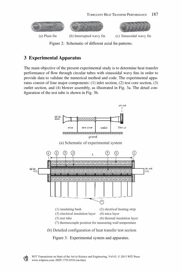
Figure 2 shows the schematic view of three fi n patterns in axial direction: (a) plain fi n, (b) interrupted wavy fi n, and (c) sinusoidal wavy fi n.
(a) S-shape (b) Z-shape (c) V-shape
Figure 1: Cross-sectional view of internally fi nned tube.
The main objective of the present experimental study is to determine heat transfer performance of fl ow through circular tubes with sinusoidal wavy fi ns in order to provide data to validate the numerical method and code. The experimental appa-ratus consist of four major components: (1) inlet section, (2) test core section, (3) outlet section, and (4) blower assembly, as illustrated in Fig. 3a. The detail con-fi guration of the test tube is shown in Fig. 3b.
Figure 2: Schematic of different axial fi n patterns.
Figure 3: Experimental system and apparatus.
(a) Plain fin (b) Interrupted wavy fin (c) Sinusoidal wavy fin
(a) Schematic of experimental system
(1) insulating bush (2) electrical heating strip(3) electrical insulation layer (4) mica layer(5) test tube 6( ) thermal insulation layer(7) thermocouple position for measuring wall temperature
(b) Detailed configuration of heat transfer test section
Air is used as the working fl uid in the whole experimental measurement. It is sucked from the laboratory atmosphere and blown into the tested fi nned tube �. The air inside the tube is heated by the electrical heater � wrapped uniformly on the outer surface of the test tube. Over the electrical heater, the outer tube is wound with a mica sheet � and insulation tape �. Two insulating bushes � and a layer of thermal insulating material � made of plastic foam with thickness of 50 mm is used to insulate the test tube in order to minimize heat loss. A motor-drive fan is used to draw air and deliver it into the test fi nned tube through trumpet-shaped entrance. The trumpet-shaped entrance mounted grille gives nearly uniform velocity distribution at the test fi nned inlet. The control of airfl ow rate through the fi nned tube is performed by varying the motor’s speed during experiment.
The test tube and fi ns are made of copper. The detailed geometry of the test internally longitudinal fi nned tube is tabulated in Tables 2–3. The temperatures of the test tube surface are measured with the help of several thermocouples, nonuni-formly distributed along the test-tube axis direction, as shown in Fig. 3b.
The investigated parameters in these experiments are inlet and outlet fl uid bulk temperature, wall temperature, mass fl ow rate, static pressure, and heat fl ux. The accuracies of these measurements will be described as follows. The accuracy of the thermocouple readings is estimated by ± 0.2°C. At each cross section, three thermocouples are situated with equal degree along the circumfer-ential direction of the outer surface. The thermocouples are made of copper-constantan wires and calibrated before installation. The thermocouple junctions between copper tube and thermocouple contact are soft soldered to grooves milled in the wall. They are installed to be fl ushed with the outer surface of the outer tube. The air temperature at the inlet of the test section is measured using a thermometer with a resolution of 0.1 °C located in the upstream of the test section inlet and its accuracy is about ± 0.2 °C. The air temperature at the outlet of the test section is measured using three thermocouples located at three differ-ent radii at the outlet of the test section and its accuracy is also about ± 0.2°C. The atmospheric pressure is measured by a barometer with an accuracy of 0.03%. The heat fl ux of the test section is measured by an electrodynameter with a full-scale accuracy of 0.15%. The air fl ow rate is determined by a rotameter with an accuracy of 2.5%. The static pressure difference is measured between the pressure at each location and atmosphere by an inclined manometer with an accuracy of 0.1 mm water column. The power input is measured by an electro-dynamometer with an accuracy of 0.25%.
The heat balance errors between the power input and enthalpy increase of air for all test points are no more than 7% in turbulent fl ow.
The method of experimental error analysis adopted is that recommended by Kline and McClintock [56]. The important parameters we were concerned about are the Nusselt number, friction factor, Reynolds number, whose uncertainties at a moderate fl ow rate and average temperature are 7.8%, 8.4%, 5.7%, respectively.
The fi n effi ciency, hf, is iteratively computed by the equation for rectangular fi n with the fi n number of 2N along the circumferential section of the tube [11]. The fi n height is nearly given by lf/2N. Then
h ldf f fh l N= ⋅2 /2 (11)
where Twi and Tf are the average temperatures of inside wall and air from n cross section, respectively.
Tn
T xwi wij
n
==
∑1
1
( ) (12)
Tn
T xf fj
n
==
∑1
1
( ) (13)
where the local air bulk temperature, Tf(x), is assumed to be linearly increased along the fl uid fl ow direction under uniform heat fl ux [57].
Tf(X) = Tin + X/L(Tout–Tin) (14)
The average Darcy friction factor is defi ned as
fP L D
uh
m
=−( / )
/
Δr 2 2
(15)
where ΔP is the total pressure drop and L is the tube length with internal fi ns.
5 Numerical Model for Turbulence Flow
5.1 Turbulence Model
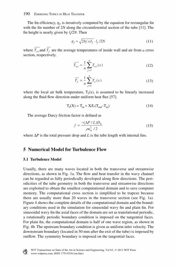
Usually, there are many waves located in both the transverse and streamwise directions, as shown in Fig. 1a. The fl ow and heat transfer in the wavy channel can be regarded as fully periodically developed along fl ow directions. The peri-odicities of the tube geometry in both the transverse and streamwise directions are exploited to obtain the smallest computational domain and to save computer memory. The computational cross section is simplifi ed to be trapeze because there are usually more than 20 waves in the transverse section (see Fig. 1a). Figure 4 shows the complete details of the computational domain and the bound-ary conditions used in the simulation for sinusoidal wavy fi n and plain fi n. For sinusoidal wavy fi n the axial faces of the domain are set as translational periodic, a rotationally periodic boundary condition is imposed on the tangential faces. For plain fi n, the computational domain is half of one wave region, as shown in Fig. 4b. The upstream boundary condition is given as uniform inlet velocity. The downstream boundary (located in 50 mm after the exit of the tube) is imposed by outfl ow. The symmetry boundary is imposed on the tangential faces.
An adiabatic boundary condition is imposed on both ends of the outer-tube and the inner-tube wall surface. The conjugated convective heat transfer is considered, which means that the fi ns are located in the computational domain (see Fig. 4). The fi n thickness is regarded as ‘thin wall’, which means the fi n is only a surface with thickness of zero, and it is impermeable for ‘fl uid’. A constant wall tempera-ture boundary condition (and/or uniform heat fl ux) is imposed on the outer-tube surface.
The working fl uid is dry air. The fl uid is incompressible with constant physical properties and the fl ow is assumed to be turbulent, steady, three dimensional with no viscous dissipation. Turbulence is modeled by the k–e model by Shih et al. [58] with the wall-function method. The governing equations are written in Cartesian diffusion form as
div div( ) ( )rV grad Sf ff f= +Γ (16)
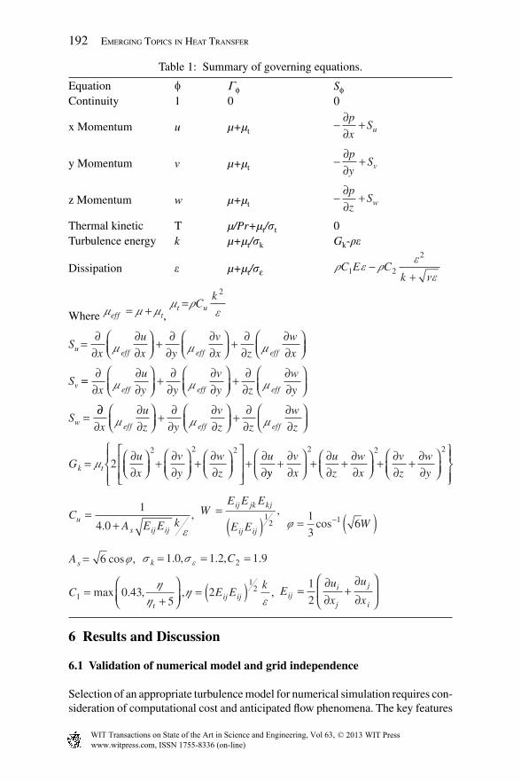
In the eqn (16), f represents generalized variables such as u, v, w, T, k, and e. Gf and Sf stand for the appropriate diffusion coeffi cients and the source terms, respectively. The detailed expressions for different variables are listed in Table 1.
The set of equations was solved by a commercially available computer soft-ware FLUENT. The pressure and velocity fi elds were linked by the semi-implicit method for pressure-linked equations consistent algorithm described by Doormal and Raithby [59]. The convection terms are handled by the quadratic upwind interpolation of convective kinematics scheme. The diffusion terms are dis-cretized with central differencing scheme. The criteria of convergence in this study are that the residual is less than 10–4 and 10–11 for the continuity and energy equations, respectively.
Thermal kinetic T µ/Pr+µt/st 0Turbulence energy k µ+µt/sk Gk-re
Dissipation e µ+µt/sε r e r e
neC E C
k1 2
2
−+
Where m m meff t= + , m r
et uCk
=2
Sx
u
x y
v
x z
w
x
S
u eff eff eff
v
=∂
∂∂∂
⎛⎝⎜
⎞⎠⎟
+∂
∂∂∂
⎛⎝⎜
⎞⎠⎟
+∂∂
∂∂
⎛⎝⎜
⎞⎠⎟m m m
==∂
∂∂∂
⎛⎝⎜
⎞⎠⎟
+∂
∂∂∂
⎛⎝⎜
⎞⎠⎟
+∂∂
∂∂
⎛⎝⎜
⎞⎠⎟
=
x
u
y y
v
y z
w
y
S
eff eff eff
w
m m m
∂∂∂
∂∂
⎛⎝⎜
⎞⎠⎟
+∂
∂∂∂
⎛⎝⎜
⎞⎠⎟
+∂∂
∂∂
⎛⎝⎜
⎞⎠⎟x
u
z y
v
z z
w
zeff eff effm m m
Gu
x
v
y
w
z
uk t=
∂∂
⎛⎝⎜
⎞⎠⎟
+∂∂
⎛⎝⎜
⎞⎠⎟
+∂∂
⎛⎝⎜
⎞⎠⎟
⎡
⎣⎢⎢
⎤
⎦⎥⎥
⎧⎨⎪
⎩⎪+
∂∂
m 22 2 2
yy
v
x
u
z
w
x
v
z
w
y+
∂∂
⎛⎝⎜
⎞⎠⎟
+∂∂
+∂∂
⎛⎝⎜
⎞⎠⎟
+∂∂
+∂∂
⎛⎝⎜
⎞⎠⎟
⎫⎬⎪
⎭⎪
2 2 2
CA E E ku
s ij ij
=+
1
4 0.,
e
WE E E
E E
ij jk kj
ij ij
=( )1
2
,
j = ( )−1
361cos W
As = 6 cos ,j s s ek C= = =1 0 1 2 1 92. , . , .
EC Ek
tij ij1
120 43
52=
+⎛⎝⎜
⎞⎠⎟
= ( )max . , , ,h
hh
e E
u
x
u
xiji
j
j
i
=∂∂
+∂∂
⎛
⎝⎜
⎞
⎠⎟
1
2
6 Results and Discussion
6.1 Validation of numerical model and grid independence
Selection of an appropriate turbulence model for numerical simulation requires con-sideration of computational cost and anticipated fl ow phenomena. The key features
of the fl ow in the internally sinusoidal fi nned tube are separation, re-circulation, and rotation. Therefore, the agreements between the calculated Nusselt number and friction factors and experimental data from sinusoidal wavy fi n are the main criteria for selecting turbulent models. In the present study, three different turbulent models (the RNG k–e model, the realizable k–e model, and the SST k–w model) are chosen to simulate the fl ow of the internally fi nned tube.
Figure 5a compares the experimentally obtained and the calculated average Nusselt number and friction factor at various Reynolds numbers with different turbulent models. From this fi gure, the realizable k–e model fi ts the experiment better than the RNG k–e and SST k–w models. The maximum differences of Nu and f are –25% and –8%, respectively, for Re ranging from 904 to 4,520. Hence, in this paper, the realizable k–e turbulence model is selected for numerical study.
To ensure the accuracy and validity of numerical results, a careful check for the grid independence of the numerical solutions has been made among three grid systems: (a) 34 × 36 × 28, (b) 42 × 44 × 40, (c) 40 × 51 × 60, as shown in Fig. 5b. It is found that in the range of studied Reynolds number (Re = 904–4,520), the relative deviations of both Nusselt numbers and friction factors between (b) and (c) are less than 5%. Hence, the mesh with 42 × 44 × 40 is selected as a reference mesh size.
6.2 Optimal ratio of blocked core-tube outer diameter to outer-tube inner diameter (do/Di)
The detailed geometrical parameters of internally fi nned tube are given in Table 2. The range of ratio of core-tube outside diameter to outer-tube inside diameter (do/Di) is from 0.25 to 0.75.
With the help of both given outer-tube outside diameter and given mass fl ow rate, when the core-tube inside diameter is reduced, both the air velocity and the pressure drop are decreased. By contrast, the fi n effi ciency is decreased with the increase of fi n height, which means higher cost of copper for manufacturing the fi ns.
Figure 5: Validation of numerical model and grid independence.
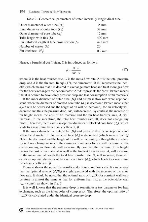
Hence, a benefi cial coeffi cient, b, is introduced as follows:
b =
ΦΔ
m
P A (17)
where Φ is the heat transfer rate, &m is the mass fl ow rate, ΔP is the total pressure drop, and A is the fi n area. In eqn (17), the numerator ‘Φ m.’ represents the ‘ben-efi t’ (which means that it is desired to exchange more heat and treat more gas fl ow for the heat exchanger) the denominator ‘ΔP A’ represents the ‘cost’ (which means that it is desired to have lower pressure drop and less consumption of fi n material).
If the inner diameter of outer tube (Di) and air mass fl ow rate were kept con-stant, when the diameter of blocked core tube (do) is decreased (which means that do/Di will be decreased and the height of fi n will be increased), the air velocity will decrease and thus the pressure drop, ΔP, will decrease. By contrast, the increase of fi n height means the cost of fi n material and the fi n heat transfer area, A, will increase. In the meantime, the total heat transfer rate, Φ, does not change any more. Therefore, there exists an optimal diameter of blocked core tube (do), which leads to a maximum benefi cial coeffi cient, b.
If the inner diameter of outer-tube (Di) and pressure drop were kept constant, when the diameter of blocked core tube (do) is decreased (which means that do/Di will be decreased and the height of fi n will be increased), although the air veloc-ity will not change so much, the cross-sectional area for air will increase, so the corresponding air fl ow rate will increase. By contrast, the increase of fi n height means the cost of fi n material as well as the fi n heat transfer area, A, will increase. In the meantime, although the total heat transfer rate, Φ, will increase, there still exists an optimal diameter of blocked core tube (do), which leads to a maximum benefi cial coeffi cient, b.
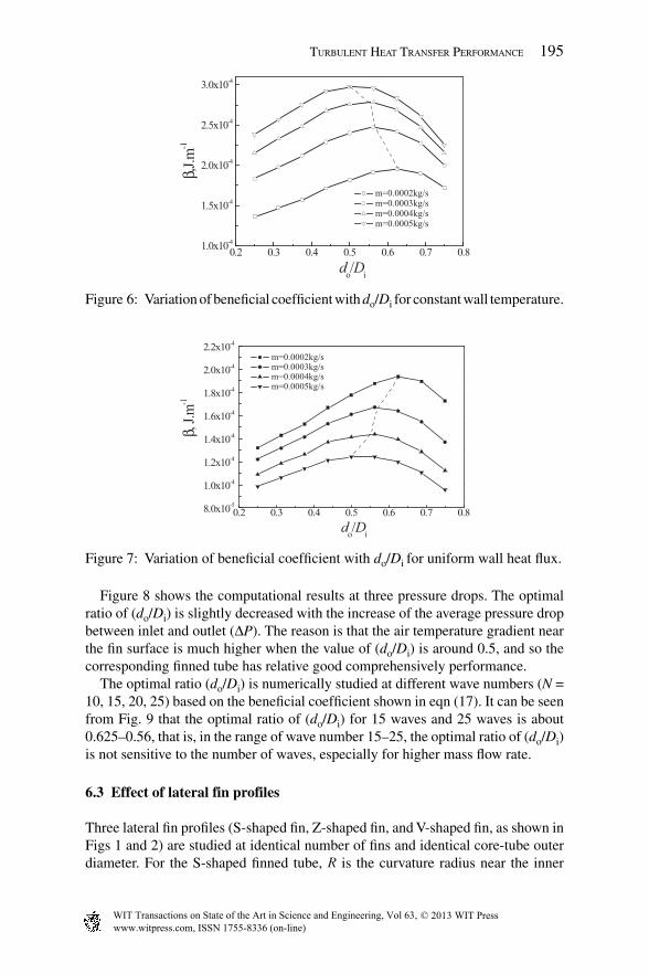
Figure 6 shows the numerical results under four mass fl ow rates. It can be seen that the optimal ratio of (do/Di) is slightly reduced with the increase of the mass fl ow rate. It should be noted that the optimal ratio of (do/Di) for constant wall tem-perature is almost the same as that for uniform heat fl ux at the outer-tube wall (qw
= const), as shown in Fig. 7.It is well known that the pressure drop is sometimes a key parameter for heat
exchanger, such as the intercooler of compressor. Therefore, the optimal ratio of (do/Di) is calculated under the identical pressure drop.
Table 2: Geometrical parameters of tested internally longitudinal tube.
Outer diameter of outer tube (Do) 35 mmInner diameter of outer tube (Di) 32 mmOuter diameter of core tube (do) 12 mmTube length with fi ns (L) 400 mmFin unfolded length at tube cross section (lf) 425 mmNumber of waves (N) 20Fin thickness (d f) 0.2 mm
Figure 8 shows the computational results at three pressure drops. The optimal ratio of (do/Di) is slightly decreased with the increase of the average pressure drop between inlet and outlet (ΔP). The reason is that the air temperature gradient near the fi n surface is much higher when the value of (do/Di) is around 0.5, and so the corresponding fi nned tube has relative good comprehensively performance.
The optimal ratio (do/Di) is numerically studied at different wave numbers (N = 10, 15, 20, 25) based on the benefi cial coeffi cient shown in eqn (17). It can be seen from Fig. 9 that the optimal ratio of (do/Di) for 15 waves and 25 waves is about 0.625–0.56, that is, in the range of wave number 15–25, the optimal ratio of (do/Di) is not sensitive to the number of waves, especially for higher mass fl ow rate.
6.3 Effect of lateral fin profiles
Three lateral fi n profi les (S-shaped fi n, Z-shaped fi n, and V-shaped fi n, as shown in Figs 1 and 2) are studied at identical number of fi ns and identical core-tube outer diameter. For the S-shaped fi nned tube, R is the curvature radius near the inner
Figure 7: Variation of benefi cial coeffi cient with do/Di for uniform wall heat fl ux.
surface of outer-tube, and r is the curvature radius near the outer surface of blocked core tube, as shown in Fig. 4b.
It is known that the optimal ratio of blocked core-tube outside diameter to outer-tube inside diameter (do/Di) is about 0.5. Therefore, in this study, the numerical simulation is performed under the optimal outer diameter of core tube, do = 16 mm and inner diameter of outer-tube, Di = 32 mm.
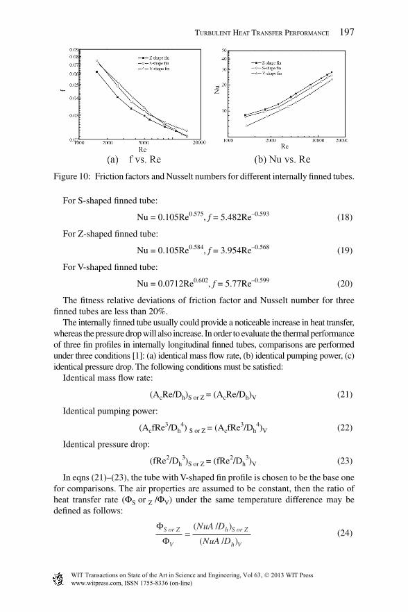
Figure 10 depicts the variation of the friction factors and average Nusselt num-bers versus Reynolds number for three different fi n profi les. As can be seen in Fig. 10a, the friction factor of the S-shaped fi nned tube is the highest at Re > 7,000, and the friction factor of the V-shaped fi nned tube is the highest at Re < 7,000. However, in Fig. 10b, the Nusselt number of the Z-shaped fi nned tube is the high-est, while that of the V-shaped fi nned tube is the lowest.
The correlated equations of both the friction factors and Nusselt numbers for three internally fi nned tubes are described as follows:
Figure 9: Variation of benefi cial coeffi cient with do/Di under different wave numbers.
0.2 0.3 0.4 0.5 0.6 0.7 0.8
1.0x10⁻⁴
2.0x10⁻⁴
3.0x10⁻⁴
4.0x10⁻⁴
5.0x10⁻⁴
6.0x10⁻⁴
do/Di
10waves 15waves 20waves 25waves
β, J.
m-1
0.2 0.3 0.4 0.5 0.6 0.7 0.81.0x10-4
2.0x10⁻⁴
3.0x10⁻⁴
4.0x10⁻⁴
5.0x10⁻⁴
6.0x10⁻⁴
7.0x10⁻⁴
8.0x10⁻⁴
9.0x10⁻⁴
β, J.
m-1
do/Di
10waves 15waves 20waves 25waves
(a) m=0.0002kg/s (b) m=0.0004kg/s
Figure 8: Variation of benefi cial coeffi cient with do/Di under identical pressure drop.
The fi tness relative deviations of friction factor and Nusselt number for three fi nned tubes are less than 20%.
The internally fi nned tube usually could provide a noticeable increase in heat transfer, whereas the pressure drop will also increase. In order to evaluate the thermal performance of three fi n profi les in internally longitudinal fi nned tubes, comparisons are performed under three conditions [1]: (a) identical mass fl ow rate, (b) identical pumping power, (c) identical pressure drop. The following conditions must be satisfi ed:
Identical mass fl ow rate:
(AcRe/Dh)S or Z = (AcRe/Dh)V (21)
Identical pumping power:
(AcfRe3/Dh4) S or Z = (AcfRe3/Dh
4)V (22)
Identical pressure drop:
(fRe2/Dh3)S or Z = (fRe2/Dh
3)V (23)
In eqns (21)–(23), the tube with V-shaped fi n profi le is chosen to be the base one for comparisons. The air properties are assumed to be constant, then the ratio of heat transfer rate (ΦS or Z /ΦV) under the same temperature difference may be defi ned as follows:
ΦΦS or Z
V
h S or Z
h V
NuA D
NuA D=
( / )
( / ) (24)
Figure 10: Friction factors and Nusselt numbers for different internally fi nned tubes.
where the subscripts ‘V’, ‘S’, and ‘Z’ represent the V-shaped fi nned tube, S-shaped fi nned tube, Z-shaped fi nned tube, respectively.
The corresponding results are depicted in Fig. 11, where the Reynolds number of the S-shaped fi n profi le case is taken as the abscissa. It can be seen that for the three conditions adopted, eqns (21)–(23), the performance of both S-shaped and Z-shaped fi nned tubes is much better than that of V-shaped fi nned tubes. The detailed results of enhanced heat transfer are illustrated as follows.
Under the condition of identical mass fl ow rate, the heat transfer of S-shaped and Z-shaped fi nned tubes is 29% and 33% higher than that of V-shaped fi nned tube, respectively. Under the condition of identical pumping power, heat transfer of S-shaped and Z-shaped fi nned tubes is 26% and 29% higher than that of V-shaped fi nned tube, respectively. Under the condition of identical pressure drop, heat transfer of S-shaped and Z-shaped fi nned tubes is about 23% and 25% higher than that of V-shaped fi nned tube. Moreover, the performance of Z-shaped fi nned tube is always superior to that of S-shaped fi nned tube under three constraints in the range of studied Reynolds numbers.
The signifi cant heat transfer enhancement obtained from both S-shaped fi nned tube and Z-shaped fi nned tubes over the V-shaped fi nned tube may be attributed to following two aspects: (a) the increase in contact surface area between the inner surface of outer tube and fi n. For example, the contact surface area for Z-shaped fi nned tube and S-shaped fi nned tube is about 13.4, 2.93 times of the area for V-shaped fi nned tube, respectively. (b) The reduction of hydraulic diameter. For example, the hydraulic diameters of V-shaped, S-shaped, and Z-shaped fi nned tubes are 2.54, 2.43, and 2.27 mm, respectively. It is well known that the decrease of channel hydraulic diameter can be used to enhance heat transfer.
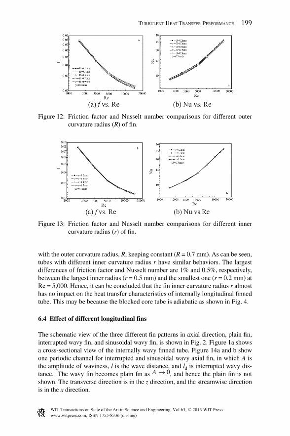
The effect of fi n outer curvature radius near the inner surface of the outer tube of S-shaped fi nned tube R, on the friction factors are presented in Fig. 12a, with the fi n inner curvature radius near the outer surface of the core tube, r, keeping con-stant (r = 0.2 mm). Figure 12b shows the corresponding variation of Nusselt num-bers versus Reynolds number. As can be expected, the Nusselt numbers decrease with the increasing of R, whereas the corresponding friction factors increase. The largest differences of friction factor and Nusselt number are both about 5% between the largest outer curvature radius (R = 0.9 mm) and the smallest one (R = 0.2 mm) at Re = 5,000.
Figure 13 depicts the variations of the friction factor and Nusselt number versus Reynolds number for different inner curvature radius r of S-shaped fi nned tube,
Figure 11: Evaluations of heat transfer performance.
with the outer curvature radius, R, keeping constant (R = 0.7 mm). As can be seen, tubes with different inner curvature radius r have similar behaviors. The largest differences of friction factor and Nusselt number are 1% and 0.5%, respectively, between the largest inner radius (r = 0.5 mm) and the smallest one (r = 0.2 mm) at Re = 5,000. Hence, it can be concluded that the fi n inner curvature radius r almost has no impact on the heat transfer characteristics of internally longitudinal fi nned tube. This may be because the blocked core tube is adiabatic as shown in Fig. 4.
6.4 Effect of different longitudinal fins
The schematic view of the three different fi n patterns in axial direction, plain fi n, interrupted wavy fi n, and sinusoidal wavy fi n, is shown in Fig. 2. Figure 1a shows a cross-sectional view of the internally wavy fi nned tube. Figure 14a and b show one periodic channel for interrupted and sinusoidal wavy axial fi n, in which A is the amplitude of waviness, l is the wave distance, and ld is interrupted wavy dis-tance. The wavy fi n becomes plain fi n as A → 0, and hence the plain fi n is not shown. The transverse direction is in the z direction, and the streamwise direction is in the x direction.
Figure 12: Friction factor and Nusselt number comparisons for different outer curvature radius (R) of fi n.
Figure 13: Friction factor and Nusselt number comparisons for different inner curvature radius (r) of fi n.
Table 3: Geometrical description of sinusoidal wavy fi nned tube.
Variables Values
Outer diameter of outer tube (Do) 28 mm Inner diameter of outer tube (Di) 26 mmOuter diameter of core tube (do) 14 mmWave distance (l) 13 mmUnfolded fi n length at tube cross section (lf) 320 mmNumber of waves in cross section (N) 25Amplitude of waviness (2A) 2.6 mmFin mean thickness (df) 0.2 mm
In the present study, because our focus is to study the infl uences of different fi n patterns on heat transfer and pressure drop performance, we simplify the actual physical model.
The computational cross section is simplifi ed to be trapeze because of a small center angle and only one periodic wave distance along streamwise direction is considered, such as sinusoidal wavy fi n, as shown in Fig. 4a. Similar treatments can be applied to the other two internally longitudinal fi ns. The periodical characteris-tics in both the axial and transverse directions are explored to obtain the smallest computational domain and to save computer memory. Figure 4a shows the com-plete details of the computational domain and the boundary conditions during the simulation. The axial faces of the domain are set as translational periodic (x direc-tion). A rotationally periodic boundary condition is imposed on the tangential faces (z direction). Because both the tube and fi n are made from copper with high thermal conductivity and the outer-tube wall is very thin, the fi n thickness is regarded as thin wall and an imposed temperature is given on the fi n surface and the tube wall.
The detailed geometrical description of tested sinusoidal wavy fi n tube is given in Table 3.
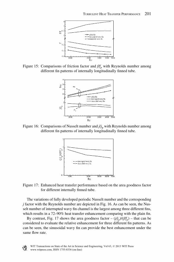
The corrugated fi n usually leads to the increased pressure drop. Figure 15 (upper graph) compares the relative friction factor f/fp for the interrupted and sinusoidal wavy fi ns, where fp represents the friction factor for a plain fi nned tube. At the same Reynolds number, the friction factor for an interrupted fi n channel is higher than that for a sinusoidal wavy fi n channel, and about 2–4 times higher than that for the plain fi n channel. By contrast, the friction factor itself decreases with the increase of the Reynolds number as shown in the lower graph of Fig. 15.
The variations of fully developed periodic Nusselt number and the corresponding j factor with the Reynolds number are depicted in Fig. 16. As can be seen, the Nus-selt number of interrupted wavy fi n channel is the largest among three different fi ns, which results in a 72–90% heat transfer enhancement comparing with the plain fi n.
By contrast, Fig. 17 shows the area goodness factor – (j/jp)/(f/fp) – that can be considered to evaluate the relative enhancement for three different fi n patterns. As can be seen, the sinusoidal wavy fi n can provide the best enhancement under the same fl ow rate.
Figure 15: Comparisons of friction factor and f/fp with Reynolds number among different fi n patterns of internally longitudinally fi nned tube.
Figure 16: Comparisons of Nusselt number and j/jp with Reynolds number among different fi n patterns of internally longitudinally fi nned tube.
Figure 17: Enhanced heat transfer performance based on the area goodness factor for different internally fi nned tube.
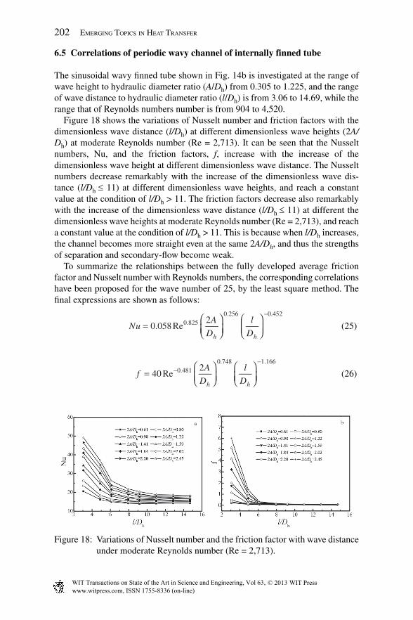
Figure 18: Variations of Nusselt number and the friction factor with wave distance under moderate Reynolds number (Re = 2,713).
6.5 Correlations of periodic wavy channel of internally finned tube
The sinusoidal wavy fi nned tube shown in Fig. 14b is investigated at the range of wave height to hydraulic diameter ratio (A/Dh) from 0.305 to 1.225, and the range of wave distance to hydraulic diameter ratio (l/Dh) is from 3.06 to 14.69, while the range that of Reynolds numbers number is from 904 to 4,520.
Figure 18 shows the variations of Nusselt number and friction factors with the dimensionless wave distance (l/Dh) at different dimensionless wave heights (2A/Dh) at moderate Reynolds number (Re = 2,713). It can be seen that the Nusselt numbers, Nu, and the friction factors, f, increase with the increase of the dimensionless wave height at different dimensionless wave distance. The Nusselt numbers decrease remarkably with the increase of the dimensionless wave dis-tance (l/Dh ≤ 11) at different dimensionless wave heights, and reach a constant value at the condition of l/Dh > 11. The friction factors decrease also remarkably with the increase of the dimensionless wave distance (l/Dh ≤ 11) at different the dimensionless wave heights at moderate Reynolds number (Re = 2,713), and reach a constant value at the condition of l/Dh > 11. This is because when l/Dh increases, the channel becomes more straight even at the same 2A/Dh, and thus the strengths of separation and secondary-fl ow become weak.
To summarize the relationships between the fully developed average friction factor and Nusselt number with Reynolds numbers, the corresponding correlations have been proposed for the wave number of 25, by the least square method. The fi nal expressions are shown as follows:
It should be noted that the ranges of dimensionless parameters for the eqns (25) and (26) are 904 ≤ Re ≤ 4,520, 0.305 ≤A/Dh ≤ 1.225, and 6.12 ≤ l/Dh ≤ 11.02 (only part of the studied l/Dh). Equation (25) correlates 90% of the numerical data for 200 cases with maximum deviation of ± 16%, and mean deviation of –2.8%. Equation (26) correlates 90% of the numerical data for 200 cases with maximum deviation of ± 20%, and mean deviation of –1.9%.
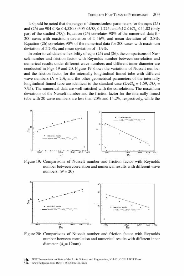
In order to validate the fl exibility of eqns (25) and (26), the comparisons of Nus-selt number and friction factor with Reynolds number between correlation and numerical results under different wave numbers and different inner diameter are conducted in Figs 19 and 20. Figure 19 shows the variations of Nusselt number and the friction factor for the internally longitudinal fi nned tube with different wave numbers (N = 20), and the other geometrical parameters of the internally longitudinal fi nned tube are identical to the standard case (2A/Dh = 1.59, l/Dh = 7.95). The numerical data are well satisfi ed with the correlations. The maximum deviations of the Nusselt number and the friction factor for the internally fi nned tube with 20 wave numbers are less than 20% and 14.2%, respectively, while the
Figure 19: Comparisons of Nusselt number and friction factor with Reynolds number between correlation and numerical results with different wave numbers. (N = 20)
0.452
f=40Re–0.481(2A/Dh)0.748(l/D
h)–1.166
Figure 20: Comparisons of Nusselt number and friction factor with Reynolds number between correlation and numerical results with different inner diameter. (do = 12mm)
corresponding mean deviations are –0.65% and 9.3%, respectively. Additionally, the maximum deviations of the Nusselt number and the friction factors for the internally fi nned tube with different inner diameter (do = 12 mm) and the other geometrical parameters of the internally longitudinal fi nned tube being identical to the standard case, are less than 19.6% and 18.4%, respectively, as illustrated in Fig. 20. The corresponding mean deviations are 0.32% and 16.1%, respectively.
7 Conclusion
Heat transfer and pressure drop performance of internally fi nned tubes with blocked core tube was numerically investigated using a commercial software FLUENT at turbulent fl ow.
Firstly, the optimization for the ratio of core-tube outside diameter to outer-tube inside diameter (do/Di) is obtainable according to the benefi cial coeffi cient. The range of optimal value is from 0.44 to 0.625 and not sensitive to the wave numbers, in the range of wave number 15–25, especially for higher mass fl ow rate.
Secondly, lateral fi n profi les (S shape, Z shape, and V shape) and longitudinal fi n patterns (interrupted wavy fi n, sinusoidal wavy, fi n and plain fi n) are studied. The Nusselt numbers of S-shaped and Z-shaped fi nned tubes are higher than that of V-shaped fi nned tube. In addition, the friction factor of V-shaped fi nned tube is the lowest at the studied range of Reynolds number under three constraints, namely, identical mass fl ow rate, identical pumping power, and identical pressure drop. The heat transfer performances of S-shaped and Z-shaped fi nned tubes are superior to that of V-shaped fi nned tube. Moreover, the heat transfer performance of Z-shaped fi nned tube is better than that of S-shaped fi nned tube. Furthermore, the fi n outer curvature radius (R) of the S-shaped fi nned tube has an appreciable effect on heat transfer, whereas the fi n inner curvature radius (r) has little impact on heat transfer. Hence, when manufacturing the internally fi nned tube with S-shaped fi n, it is better to select smaller outer curvature radius (R) although it is usually diffi cult to obtain the Z-shaped fi nned tube from the manufacturing point of view.
The overall heat transfer coeffi cients in wavy channels are higher than those in a plain fi n channel, while with larger pressure drop penalties. At the same wavi-ness, the interrupted wavy fi n tube could enhance heat transfer by 72–90%, but with more than two to four times of pressure drop penalty. Among the studied fi ns, the sinusoidal wavy fi n has the best comprehensive performance.
Finally, turbulent fl ow and convective heat transfer in sinusoidal wavy channel of internally longitudinal fi nned tube have been numerically studied. Both the Nusselt number and the friction factor increase with the increase of the wave height and with the decrease of the wave distance. The correlations of Nusselt number and the friction factor with the Reynolds number and dimensionless fi n wave height and dimensionless wave distance are found with the ranges of parameters 904 ≤ Re ≤ 4,520, 0.305 ≤ A/Dh ≤ 1.225, 6.12 ≤ l/Dh ≤ 11.02.
This work was supported by the National Natural Science Foundation of China (Grant Nos. 51025623 and 51230603) and the National Basic Research Program of China (973 Program, No. 2012CB720402).
Nomenclature
A Amplitude of waviness (m), Heat transfer surface area (m2)Ac Cross sectional area (m2)
C1,C2 Constants in the reliable k − e model
Cu Coeffi cient in the reliable k − e modelcp Specifi c heat capacity of air (J/kg K)Dh Hydraulic diameter (m)Di Inner diameter of outer tube (m)Do Outer diameter of outer tube (m)di Inner diameter of core tube (m)do Outer diameter of core tube (m)f Darcy friction factorG Production of turbulent kinetic energyh Average heat transfer coeffi cient (W m–2 K–1)j Columbum factork Turbulent kinetic energy (m2 s–2)L Tube length (m)l Turbulence mixing length (m), wave distance (m)ld Interrupted wavy distance (m)lf Periphery unfolded length of the wavy fi n (m)m Mass fl ow rate (kg s–1)N Wave number of the cross-sectional fi nned tubeNu Average Nusselt numberPr Prandtl numberq Wall heat fl ux (Wm–2)Q Volumetric fl ow rate (m3/h)
R, rCurvature radius near the inner surface of the outer-tube (m), curvature radius near the outer surface of the core-tube (m)
Re Reynolds numberSu Source term for u velocitySv Source term for v velocitySw Source term for w velocity
Sf Source terms for generalized variablesT Temperature (K)
Average temperature of fl uid (K)um Average velocity in the axial direction (m s–1)u,v,w Velocity component (m s–1)x, y, z Cartesian coordinatesx Axial position (m)
Greek symbolsb Benefi cial coeffi cient (J m–1)Gφ Diffusion coeffi cients for general variablesΔP Pressure drop between inlet and outlet (Pa)ΔPm Average pressure drop (Pa)e Dissipation rate of turbulence energy (m–3 s–2)l Thermal conductivity (W m–1 K–1)m Dynamic viscosity (kg m–1 s–1)r Density (kg m–3)Φ Heat transfer rate (W)df Fin thickness (m)f Generalized variableshf Fin effi ciencyµeff Effective turbulent viscosity (kg m–1 s–1)µt Turbulent viscosity (kg m–1 s–1)
sk, sε, st Turbulent Prandtl numbers for diffusion of k, e, and T
Subscriptsa Airf Fin, fl uidL Tube endm Mean valuemax Maximump Plain fi n tubeS S-shaped fi nned tubeV V-shaped fi nned tubew Wallwi Inside wall of outer tubewo Outside wall of outer tubeZ Z-shaped fi nned tubex Local axial position
[1] Webb, R.L., Principles of Enhanced Heat Transfer, John Wiley & Sons, Inc: New York, pp. 209–211, 1994.
[2] Saad, A.E., Sayed, A.E., Mohamed, E.A. & Mohamed, M.S., Experimental study of turbulent fl ow inside a circular tube with longitudinal interrupted fi ns in the streamwise direction. Experimental Thermal Fluid Science, 15(1), pp. 1–15, 1997.
[3] Huq, M., Huq, A., Rahman, A.M. & Muhammad, M., Experimental measure-ments of heat transfer in an internally fi nned tube. International Communica-tions in Heat and Mass Transfer, 25(5), pp. 619–630, 1998.
[4] Braga, C.V.M. & Saboya, F.E.M., Turbulent heat transfer, pressure drop and fi n effi ciency in annular regions with continuous longitudinal rectangular fi ns. Experimental Thermal Fluid Science, 20(2), pp. 55–56, 1999.
[5] Dagtekin, I., Oztop, H.F. & Sahin, A.Z., An analysis of entropy generation through a circular duct with different shaped longitudinal fi ns for laminar fl ow. International Journal of Heat and Mass Transfer, 48(1), pp. 171–181, 2005.
[6] Yu, B., Nie, J.H., Wang, Q.W. & Tao, W.Q., Experimental study on the pres-sure drop and heat transfer characteristics of tubes with internal wave-like longitudinal fi ns. Heat and Mass Transfer, 35, pp. 65–73, 1999.
[7] Yu, B. & Tao, W.Q., Pressure drop and heat transfer characteristics of turbu-lent fl ow in annular tubes with internal wave-like longitudinal fi ns. Heat and Mass Transfer, 40, pp. 643–651, 2004.
[8] London, A.L. & Shah, R.K., Offset rectangular plate-fi n surfaces: heat trans-fer and fl ow friction. Journal of Engineering Power, 90, pp. 218–228, 1968.
[9] Rustun, I.M. & Saliman, H.M., Experimental investigation of laminar mixed convection in tubes with longitudinal internal fi ns. ASME Journal of Heat Transfer, 110, pp. 310–313, 1988.
[10] Naik, S., Probert, S.D. & Bryden, I.G., Heat transfer characteristics of shrouded longitudinal ribs in turbulent forced convection. International Journal of Heat and Fluid Flow, 20(4), pp. 374–384, 1999.
[11] Patankar S.V., Ivanovic, M. & Sparrow, E.M., Analysis of turbulent fl ow and heat transfer in internally fi nned tubes and annulus. ASME Journal of Heat Transfer, 101, pp. 29–37, 1979.
[12] Schmidt, E., Die Warmeueberragung durch Rippen. Zeit schrift des Vereines deutscher Ingenienure, 70, pp. 885–951, 1926.
[13] Fabbri, G., Heat transfer optimization in internally fi nned tubes under laminar fl ow conditions. International Journal of Heat and Mass Transfer, 41(10), pp. 1243–1253, 1998.
[14] Fabbri, G., Optimum profi les for asymmetrical longitudinal fi ns in cylindrical ducts. International Journal of Heat and Mass Transfer, 42(3), pp. 511–523, 1999.
[15] Fabbri, G., 2004, Effect of viscous dissipation on the optimization of the heat transfer in internally fi nned tubes. International Journal of Heat and Mass Transfer, 47, pp. 3003–3015.
[16] Zeitoun, O. & Hegazy, A.S., Heat transfer for laminar fl ow in internally fi nned pipes with different fi n heights and uniform wall temperature. Heat and Mass Transfer, 40, pp. 253–259, 2004.
[17] Kumar, R., Three-dimensional natural convective fl ow in a vertical annu-lus with longitudinal fi ns. International Journal of Heat and Mass Transfer, 40(14), pp. 3323–3334, 1997.
[18] Alam, I. & Ghoshdastidar, P.S., A study of heat transfer effectiveness of circu-lar tubes with internal l longitudinal fi ns having tapered lateral profi les. Inter-national Journal of Heat and Mass Transfer, 45(6), pp. 1371–1376, 2002.
[19] Queipo, N., Devarakkkonda, R. & Humphrey, J.A.C., Genetic algorithms for thermosciences research: application to the optimized cooling of elec-tronic components. International Journal of Heat and Mass Transfer, 37(6), pp. 893–908, 1994.
[20] Leu, J.S., Liu, M.S., Liaw, J.S. & Wang, C.C., A numerical investigation of louvered fi n-and-tube heat exchangers having circular and oval tube con-fi gurations. International Journal of Heat and Mass Transfer, 44(22), pp. 4235–4243, 2001.
[21] Leu, J.S., Wu, Y.H. & Jang J.Y., Heat transfer and fl uid fl ow analysis in plate-fi n and tube heat exchangers with a pair of block shape vortex generator. International Journal of Heat and Mass Transfer, 47, pp. 4327–4338, 2004.
[22] Olson, D.A., Heat transfer in thin, compact heat exchangers with circular, rectangular, or pin-fi n fl ow passages. ASME Journal of Heat Transfer, 114, pp. 373–382, 1992.
[23] Liu, X.Y. & Jensen, M.K., Numerical investigation of turbulent fl ow and heat transfer in internally fi nned tubes. Journal of Enhanced Heat Transfer, 6(2–4), pp. 105–119, 1999.
[24] Sarkhi, A.A. & Nada, E.A., Characteristics of forced convection heat transfer in vertical internally fi nned tube. International Communications in Heat and Mass Transfer, 32, pp. 557–564, 2005.
[25] Zhang, Y.M. & Faghri, A., Heat transfer enhancement in latent heat transfer thermal energy storage system by using the internally fi nned tube. Interna-tional Journal of Heat and Mass Transfer, 39, pp. 3165–3173, 1996.
[26] Campo, A. & Chang, J., 1997, Correlation equations for friction factors and convective coeffi cients in tubes containing bundles of internal longitudinal fi ns. Heat and Mass Transfer, 33, pp. 225–232.
[27] Bhatia, R.S. & Webb, R.L., Numerical study of turbulent fl ow and heat trans-fer in micro-fi n tubes–part1, model validation. Journal of Enhanced Heat Transfer, 8, pp. 291–304, 2001.
[28] Rush, T.A., Newell, T.A. & Jacobi, A.M., An experimental study of fl ow and heat transfer in sinusoidal wavy passages. International Journal of Heat Mass Transfer, 42(9), pp. 1541–1553, 1999.
[29] Manglik, R.M., Zhang, J.H. & Muley, A., Low Reynolds number forced con-vection in three-dimensional wavy-plate-fi n compact channels: fi n density effects. International Journal of Heat and Mass Transfer, 48, pp. 1439–1449, 2005.
[30] Jang, J.Y. & Chen, L.K., Numerical analysis of heat transfer and fl uid fl ow in a three-dimensional wavy-fi n and tube heat exchanger. International Journal of Heat and Mass Transfer, 40(16), pp. 3981–3990, 1997.
[31] Utriainen, E. & Sunden, B., A numerical investigation of primary surface rounded cross wavy ducts. Heat and Mass Transfer, 38, pp. 537–542, 2002.
[32] Maranzana, G., Perry, I. & Maillet, D., Mini- and micro-channels: infl uence of axial conduction in the walls. International Journal of Heat and Mass Transfer, 47, pp. 3993–4004, 2004.
[33] Tsai, S.F., Sheu, T.W.H. & Lee, S.M., Heat transfer in a conjugate heat exchanger with a wavy fi n surface. International Journal of Heat and Mass Transfer, 42, pp. 1735–1745, 1999.
[34] Lozzaa, G. & Merlob, U., An experimental investigation of heat transfer and friction losses of interrupted and wavy fi ns for fi n-and-tube heat exchangers. International Journal of Refrigeration, 24, pp. 409–416, 2001.
[35] Mori, S., Sakakibara, M. & Tanimoto, A., Steady heat transfer to laminar fl ow in a circular tube with conduction in tube wall. Heat Transfer Japanese Research, 3, pp. 37–46, 1974.
[36] Faghri, M. & Sparrow, E.M., Simultaneous wall and fl uid axial conduction in laminar pipe-fl ow heat transfer. Transactions ASME Journal of Heat Trans-fer, 102, pp. 58–43, 1980.
[37] Vick, B. & Özisik, M.N., An exact analysis of low Peclet number heat trans-fer in laminar fl ow with axial conduction. Letters in Heat and Mass Transfer, 8(1), pp. 1–10, 1981.
[38] Campo, A. & Auguste, J.C., Axial conduction in laminar pipe fl ows with nonlinear wall heat fl uxes. International Journal of Heat and Mass Transfer, 21(12), pp. 1597–1607, 1978.
[39] Soliman, H.M., Analysis of low Peclet heat transfer during slug-fl ow in tubes with axial wall conduction. ASME Journal of Heat Transfer, 106, pp. 782–788, 1984.
[40] Barozzi, G.S. & Pagliarini, G., A method to solve conjugate heat transfer problems: the case of fully developed laminar fl ow in a pipe. Transactions ASME Journal of Heat Transfer, 107, pp. 77–83, 1985.
[41] Wiievsundera, N.J., Laminar forced convection in circular and fl at ducts with wall axial conduction and external convection. International Journal of Heat and Mass Transfer, 29, pp. 797–807, 1986.
[42] Pagliarini, G., Effects of axial conduction in the wall and the fl uid on conju-gate heat transfer in thick-walled circular tubes. International Communica-tions in Heat and Mass Transfer, 15(5), pp. 581–591, 1988.
[43] Campo, A. & Shuler, C., Heat transfer in laminar fl ow through circular tubes accounting for two-dimensional wall conduction. International Journal of Heat and Mass Transfer, 31, pp. 2251–2259, 1988.
[44] Faghri, A., Chen, M.M. & Mahefkey, E.T., Simultaneous axial conduction in the fl uid and in the pipe wall for forced convective laminar fl ow with blow-ing and suction at the wall. International Journal of Heat and Mass Transfer, 32, pp. 281–288, 1989.
[45] Bilir, S., Laminar fl ow heat transfer in pipes including two-dimensional wall and fl uid axial conduction. International Journal of Heat and Mass Transfer, 38, pp. 1619–1625, 1995.
[46] Bilir, S. & Ates, A., Transient conjugated heat transfer in thick walled pipes with convective boundary conditions. International Journal of Heat and Mass Transfer, 46, pp. 2701–2709, 2003.
[47] Piva, S., Axial wall conduction preheating effects in high Peclet number laminar forced convection. International Journal of Heat and Mass Transfer, 39(16), pp. 3511–3517, 1996.
[48] Yin, X. & Bau, H.H., The conjugate Graetz problem with axial conduction. ASME Journal of Heat Transfer, 118, pp. 482–485, 1996.
[49] Barletta, A. & Schio, E.R., Periodic forced convection with axial heat con-duction in a circular duct. International Journal of Heat and Mass Transfer, 43, pp. 2949–2960, 2000.
[50] Jang, J.Y. & Chen, L.K., Numerical analysis of heat transfer and fl uid fl ow in a three-dimensional wavy-fi n and tube heat exchanger. International Journal of Heat and Mass Transfer, 40, pp. 3981–3990, 1997.
[51] Huq, M. & Huq, A.M.A., Experimental measurements of the heat transfer in an internally fi nned tube. International Communications in Heat and Mass Transfer, 25, pp. 619–630, 1998.
[52] Wang, Q.W., Lin, M. & Zeng, M., Effect of blocked core-tube diameter on heat transfer performance of internally longitudinal fi nned tubes. Heat Trans-fer Engineering, 29, pp. 107–115, 2008.
[53] Wang, Q.W., Lin, M. & Zeng, M., Effect of lateral fi n profi les on turbulent fl ow and heat transfer performance of internally fi nned tubes. Applied Ther-mal Engineering, 29, pp. 3006–3013, 2009.
[54] Wang, Q.W., Lin, M., Zeng, M. & Tian, L., Computational analysis of heat transfer and pressure drop performance for internally fi nned tubes with three different longitudinal wavy fi ns. Heat Mass Transfer, 45, pp. 147–156, 2008.
[55] Wang, Q.W., Lin, M., Zeng, M. & Tian, L., Investigation of turbulent fl ow and heat transfer in periodic wavy channel of internally fi nned blocked-core tube. ASME Journal of Heat and Mass Transfer, 130(6), article number 061801, 2008.
[56] Kline, S.J. & McClintock, F.A., Describing uncertainties in single sample experiments. Mech. Eng. Am. Soc. Mech. Eng., 75, pp. 3–8, 1953.
[57] Holman, J.P., Heat Transfer, 9th, Chapter5, McGraw-Hill: New York, 2002.[58] Shih, T.H., Liou, W.W., Shabbrir, A., Yang, Z.G. & Zhu, J., A New k − e eddy
viscosity model for high Reynolds number turbulent fl ows. Computa tional Fluids, 24, pp. 227–238, 1995.
[59] Doormal, J.P.V. & Raithby,G.G., Enhancement of the SIMPLE method for predicting incompressible fl uid fl ows. Numerical Heat Transfer, 7, pp. 147–163, 1984.