Chapter 7 - 1 ISSUES TO ADDRESS... • Why are dislocations observed primarily in metals and alloys? • How are strength and dislocation motion related? • How do we increase strength? • How can heating change strength and other properties? Chapter 7: Dislocations & Strengthening Mechanisms
Transcript
Chapter 7 - 1
ISSUES TO ADDRESS...
• Why are dislocations observed primarily in metals
and alloys?
• How are strength and dislocation motion related?
• How do we increase strength?
• How can heating change strength and other properties?
Chapter 7: Dislocations & Strengthening
Mechanisms
Chapter 7 - 2
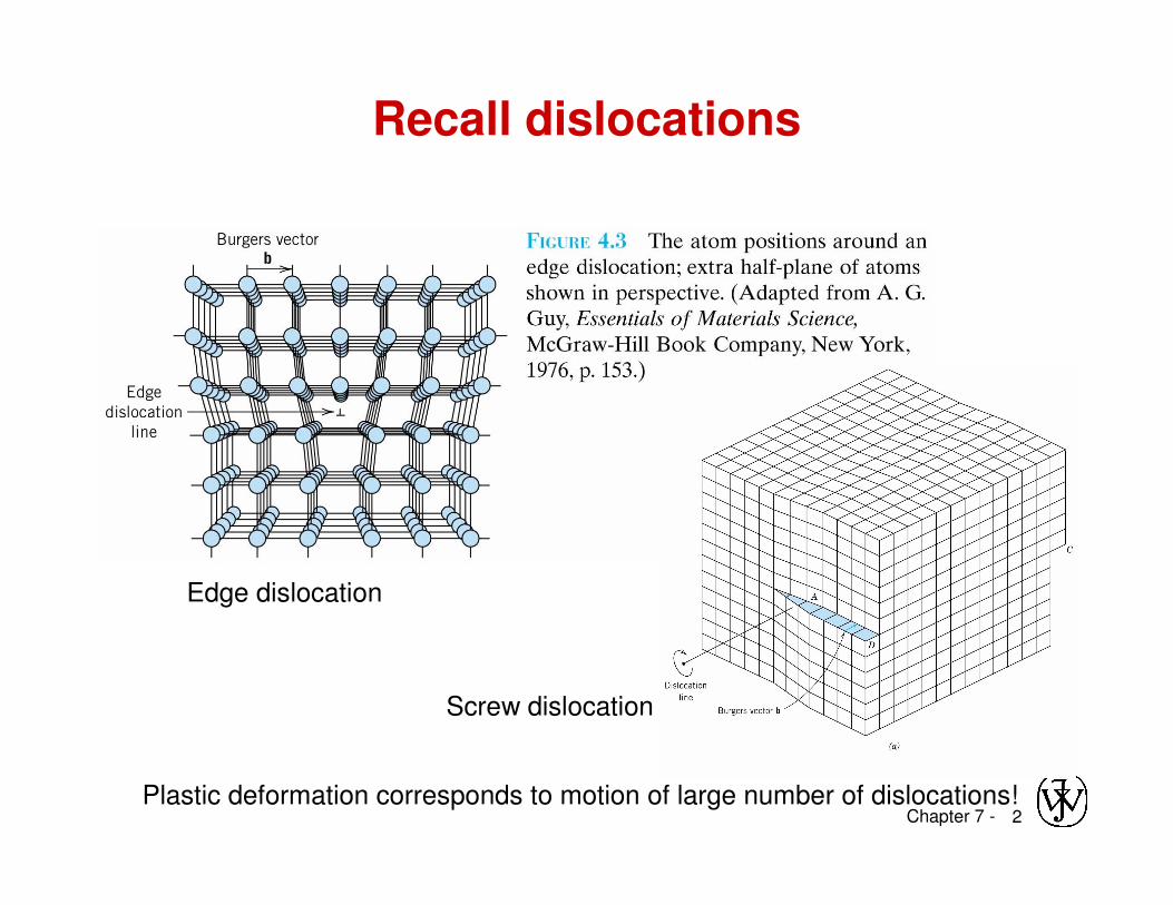
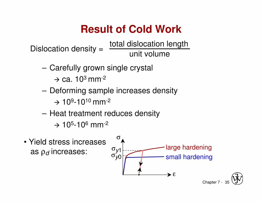
Recall dislocations
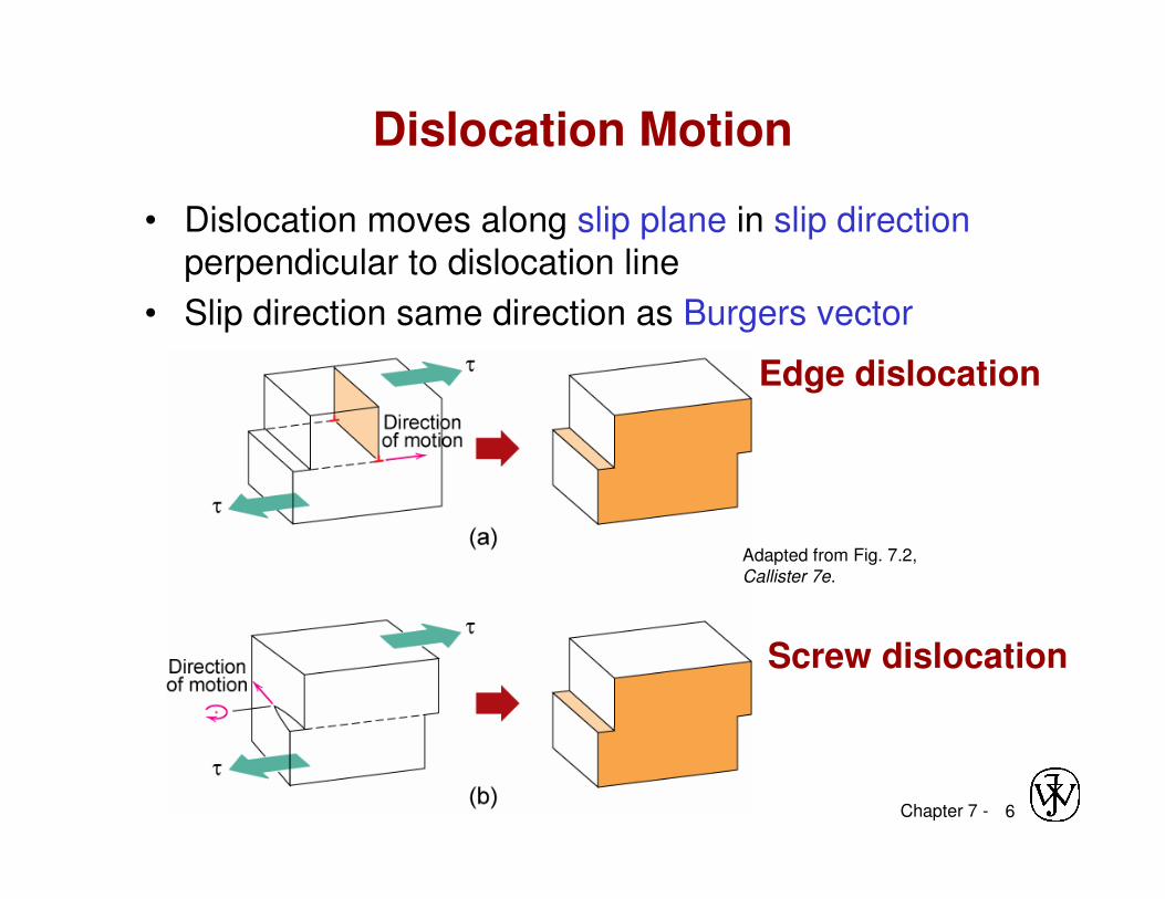
Edge dislocation
Screw dislocation
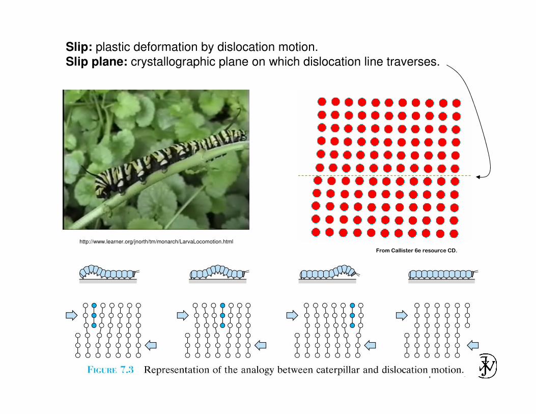
Plastic deformation corresponds to motion of large number of dislocations!
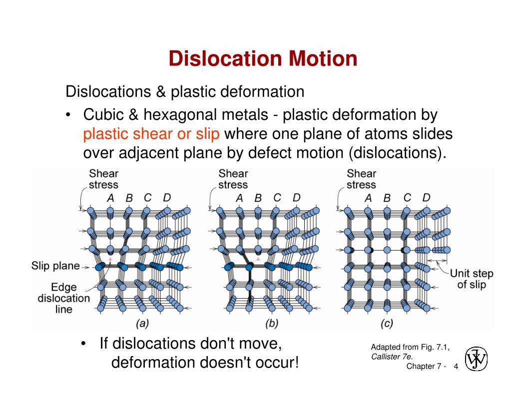
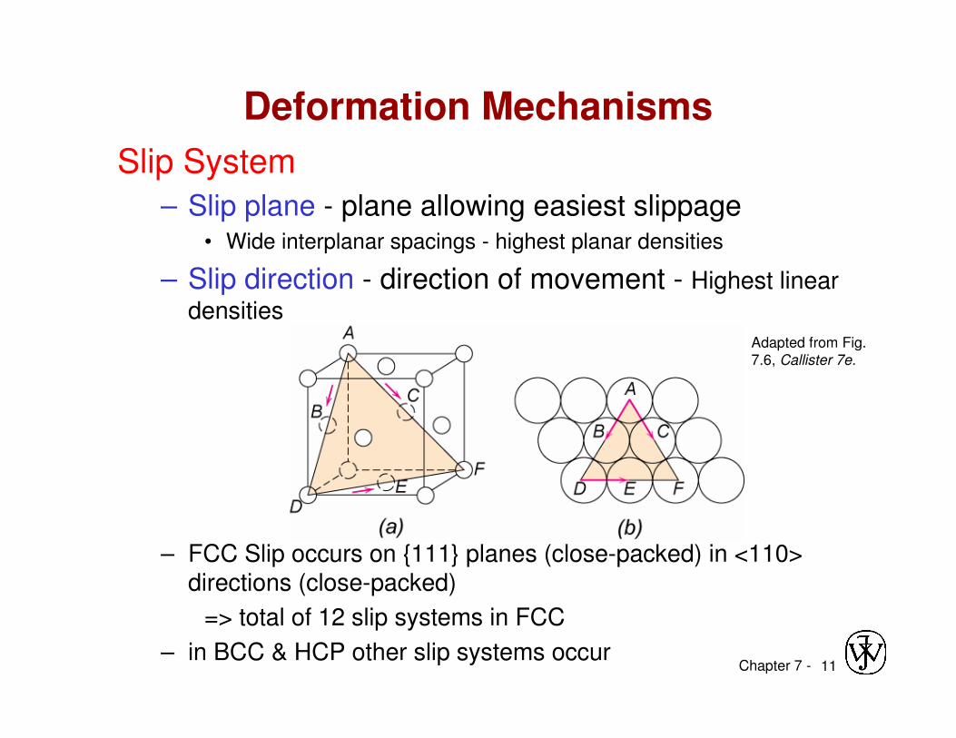
• Cubic & hexagonal metals - plastic deformation by plastic shear or slip where one plane of atoms slides over adjacent plane by defect motion (dislocations).
• If dislocations don't move, deformation doesn't occur!
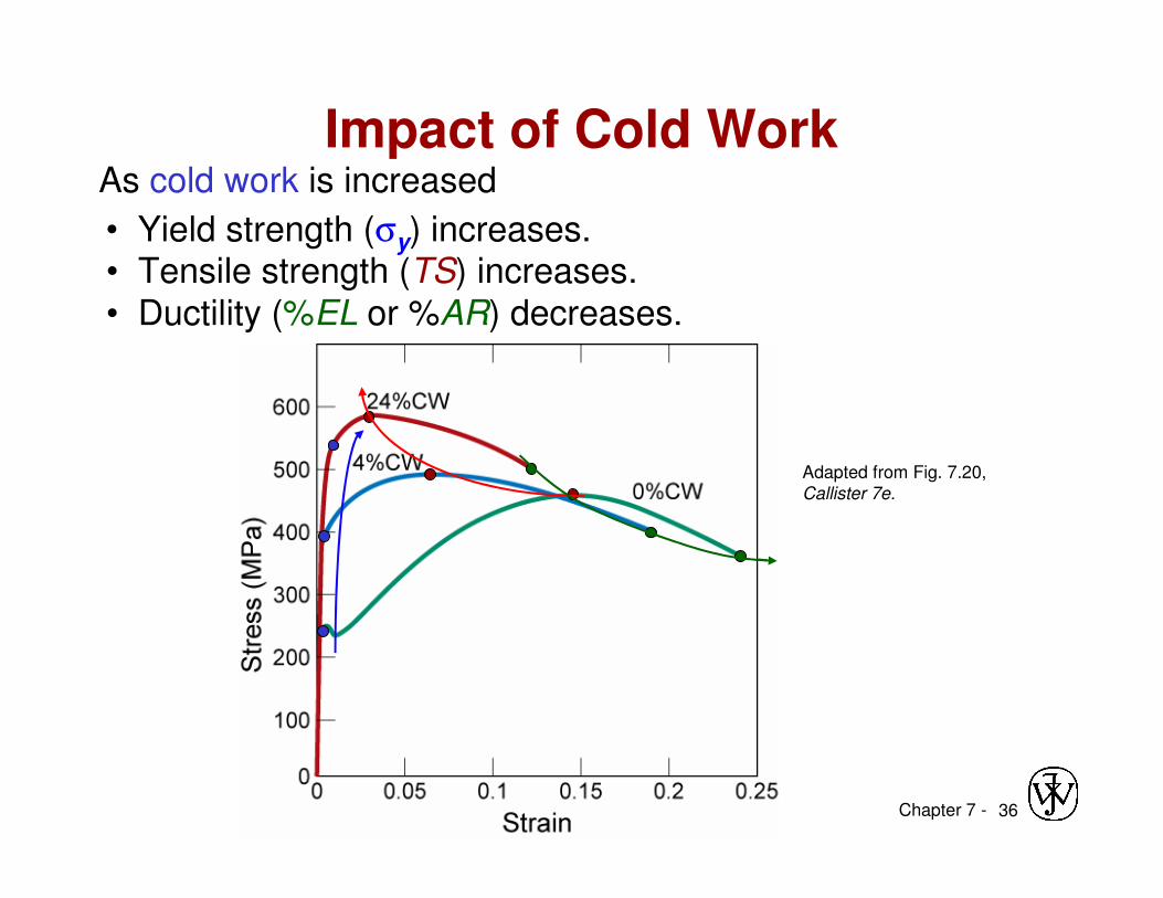
Adapted from Fig. 7.19, Callister 7e. (Fig. 7.19 is adapted from Metals Handbook: Properties and Selection:
Iron and Steels, Vol. 1, 9th ed., B. Bardes (Ed.), American Society for Metals, 1978, p. 226; and Metals
Handbook: Properties and Selection: Nonferrous Alloys and Pure Metals, Vol. 2, 9th ed., H. Baker (Managing Ed.), American Society for Metals, 1979, p. 276 and 327.)
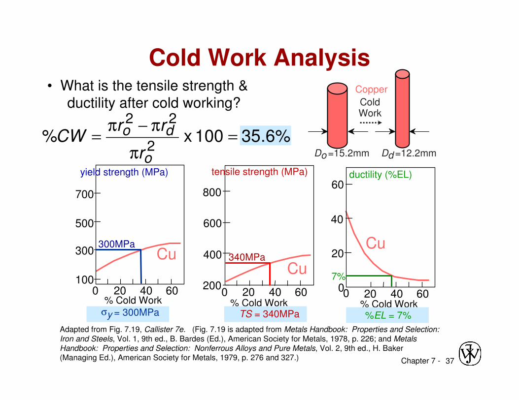
%6.35100 x %2
22
=π
π−π=
o
do
r
rrCW
Cold Work Analysis
% Cold Work
100
300
500
700
Cu
200 40 60
yield strength (MPa)
σy = 300MPa
300MPa
% Cold Work
tensile strength (MPa)
200
Cu
0
400
600
800
20 40 60
ductility (%EL)
% Cold Work
20
40
60
20 40 6000
Cu
Do =15.2mm
Cold Work
Dd =12.2mm
Copper
340MPa
TS = 340MPa
7%
%EL = 7%
Chapter 7 - 38
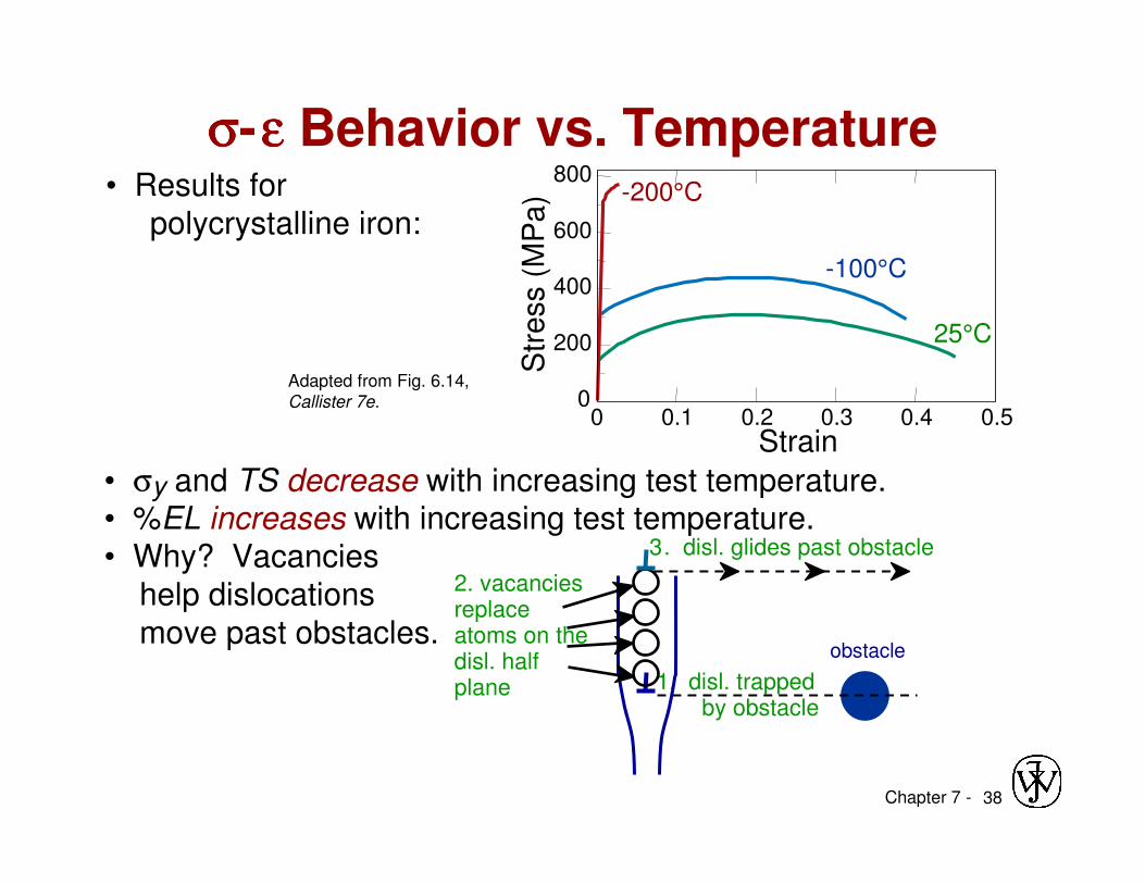
• Results for
polycrystalline iron:
• σy and TS decrease with increasing test temperature.• %EL increases with increasing test temperature.• Why? Vacancies
help dislocations
move past obstacles.
Adapted from Fig. 6.14, Callister 7e.
σσσσ-εεεε Behavior vs. Temperature
2. vacancies replace atoms on the disl. half plane
3. disl. glides past obstacle
-200°C
-100°C
25°C
800
600
400
200
0
Strain
Str
ess (
MP
a)
0 0.1 0.2 0.3 0.4 0.5
1. disl. trapped by obstacle
obstacle
Chapter 7 - 39
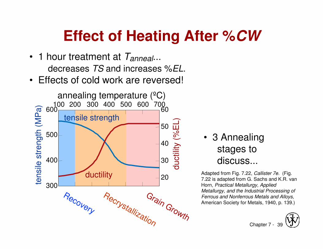
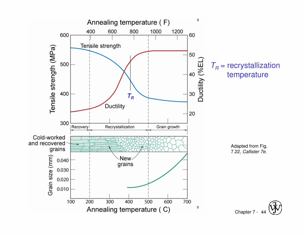
• 1 hour treatment at Tanneal...decreases TS and increases %EL.
• Effects of cold work are reversed!
• 3 Annealingstages todiscuss...
Adapted from Fig. 7.22, Callister 7e. (Fig.7.22 is adapted from G. Sachs and K.R. van Horn, Practical Metallurgy, Applied Metallurgy, and the Industrial Processing of
Ferrous and Nonferrous Metals and Alloys, American Society for Metals, 1940, p. 139.)
Effect of Heating After %CWte
nsile
str
eng
th (
MP
a)
du
ctilit
y (
%E
L)tensile strength
ductility
Recovery
Recrystallization
Grain Growth
600
300
400
500
60
50
40
30
20
annealing temperature (ºC)200100 300 400 500 600 700
Chapter 7 - 40
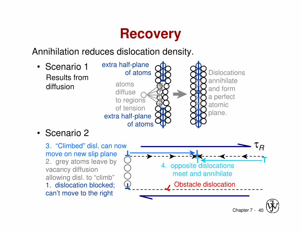
Annihilation reduces dislocation density.
Recovery
• Scenario 1Results from diffusion
• Scenario 2
4. opposite dislocations meet and annihilate
Dislocations annihilate and form a perfect atomic plane.
extra half-plane of atoms
extra half-plane of atoms
atoms diffuse to regions of tension
2. grey atoms leave by vacancy diffusion allowing disl. to “climb”
τR
1. dislocation blocked; can’t move to the right
Obstacle dislocation
3. “Climbed” disl. can now move on new slip plane
Chapter 7 - 41
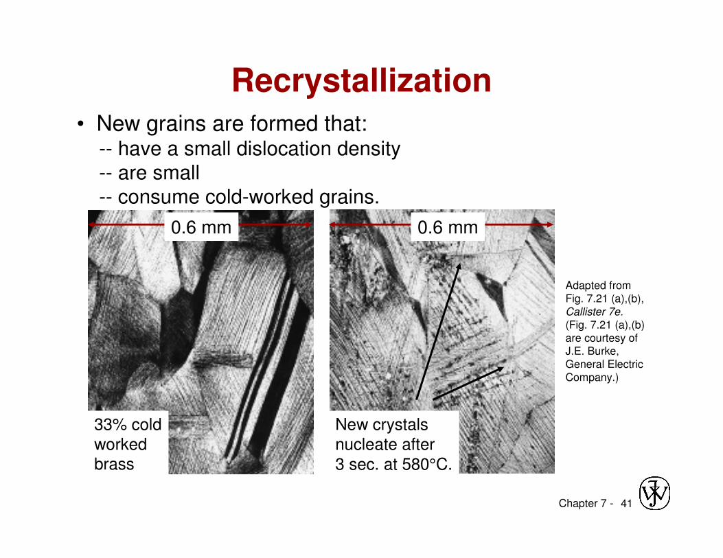
• New grains are formed that:-- have a small dislocation density
-- are small
-- consume cold-worked grains.
Adapted from Fig. 7.21 (a),(b), Callister 7e.
(Fig. 7.21 (a),(b) are courtesy of J.E. Burke, General Electric Company.)
33% cold
workedbrass
New crystals
nucleate after
3 sec. at 580°C.
0.6 mm 0.6 mm
Recrystallization
Chapter 7 - 42
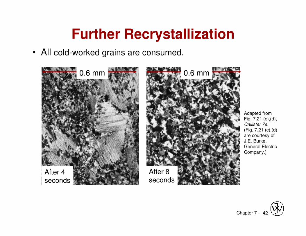
• All cold-worked grains are consumed.
Adapted from Fig. 7.21 (c),(d), Callister 7e.(Fig. 7.21 (c),(d) are courtesy of J.E. Burke, General Electric Company.)
After 4
seconds
After 8
seconds
0.6 mm0.6 mm
Further Recrystallization
Chapter 7 - 43
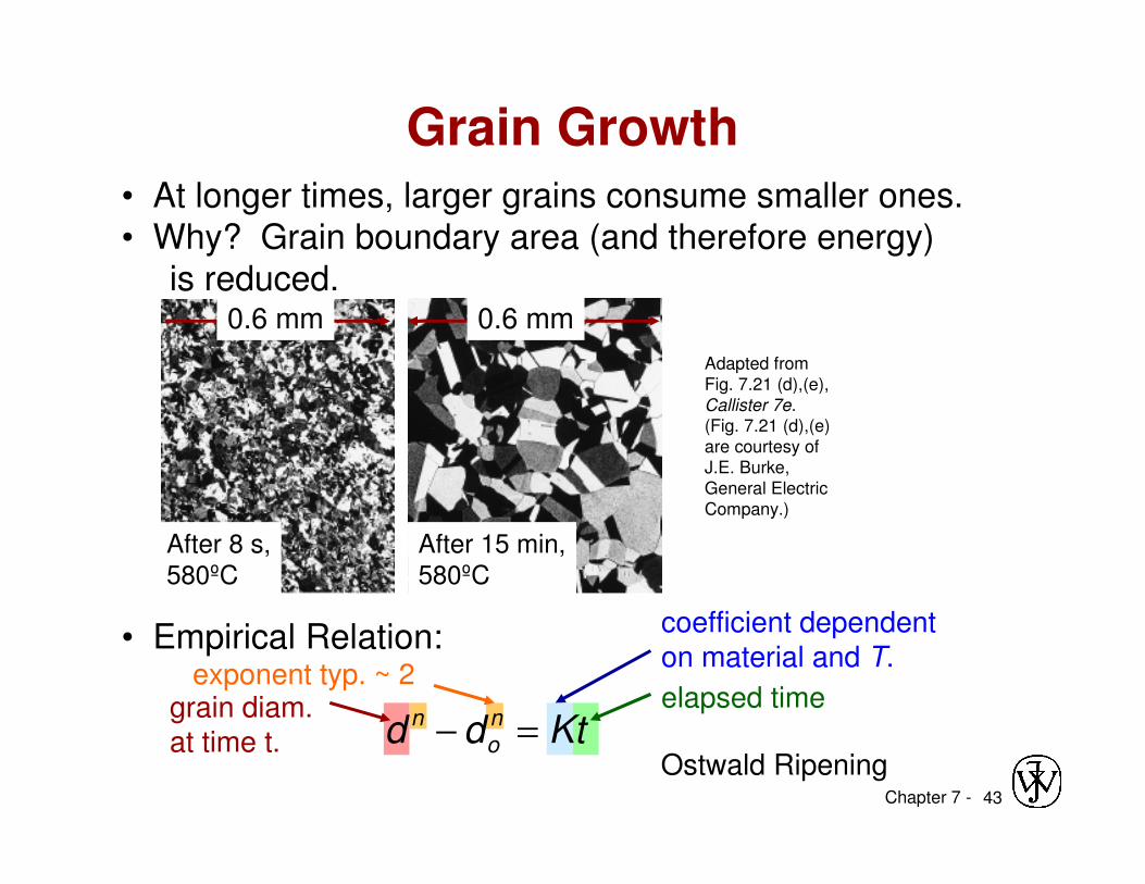
• At longer times, larger grains consume smaller ones. • Why? Grain boundary area (and therefore energy)
is reduced.
After 8 s,580ºC
After 15 min,580ºC
0.6 mm 0.6 mm
Adapted from Fig. 7.21 (d),(e), Callister 7e.(Fig. 7.21 (d),(e) are courtesy of J.E. Burke, General Electric Company.)
Grain Growth
• Empirical Relation:
Ktdd no
n =−elapsed time
coefficient dependenton material and T.
grain diam.at time t.
exponent typ. ~ 2
Ostwald Ripening
Chapter 7 - 44
TR
Adapted from Fig. 7.22, Callister 7e.
º
º
TR = recrystallization temperature
Chapter 7 - 45
Recrystallization Temperature, TR
TR = recrystallization temperature = point of
highest rate of property change
1. Tm => TR ≈ 0.3-0.6 Tm (K)
2. Due to diffusion � annealing time� TR = f(t) shorter annealing time => higher TR
3. Higher %CW => lower TR – strain hardening
4. Pure metals lower TR due to dislocation movements
• Easier to move in pure metals => lower TR
Chapter 7 - 46
Coldwork Calculations
A cylindrical rod of brass originally 0.40 in (10.2 mm) in diameter is to be cold worked by drawing. The circular cross section will be maintained during deformation. A cold-worked tensile strength in excess of 55,000 psi (380 MPa) and a ductility of at least 15 %EL are desired. Further more, the final diameter must be 0.30 in (7.6 mm). Explain how this may be accomplished.
Chapter 7 - 47
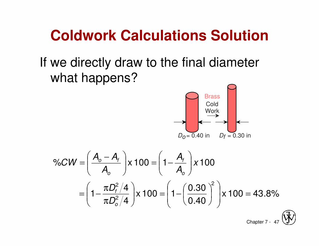
Coldwork Calculations Solution
If we directly draw to the final diameter what happens?
%843100 x 400
3001100 x
4
41
100 1100 x %
2
2
2
..
.
D
D
xA
A
A
AACW
o
f
o
f
o
fo
=
−=
π
π−=
−=
−=
Do = 0.40 in
Brass
Cold Work
Df = 0.30 in
Chapter 7 - 48
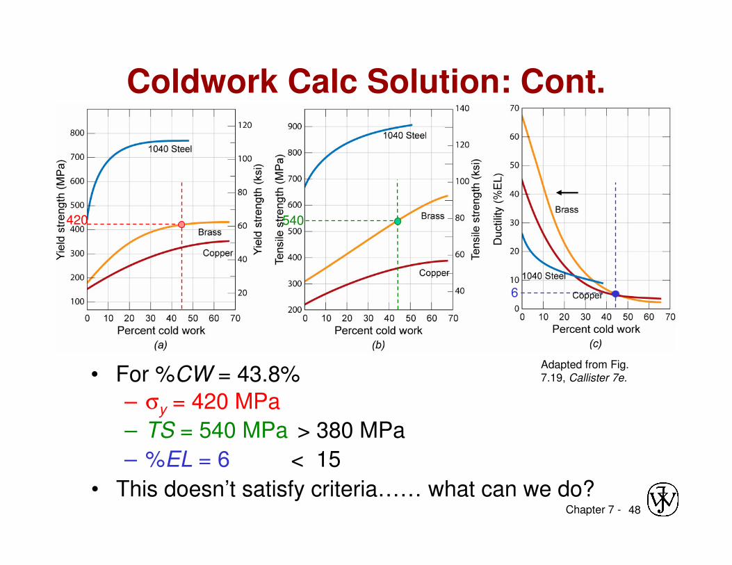
Coldwork Calc Solution: Cont.
• For %CW = 43.8%Adapted from Fig. 7.19, Callister 7e.
540420
– σy = 420 MPa
– TS = 540 MPa > 380 MPa
6
– %EL = 6 < 15
• This doesn’t satisfy criteria…… what can we do?
Chapter 7 - 49
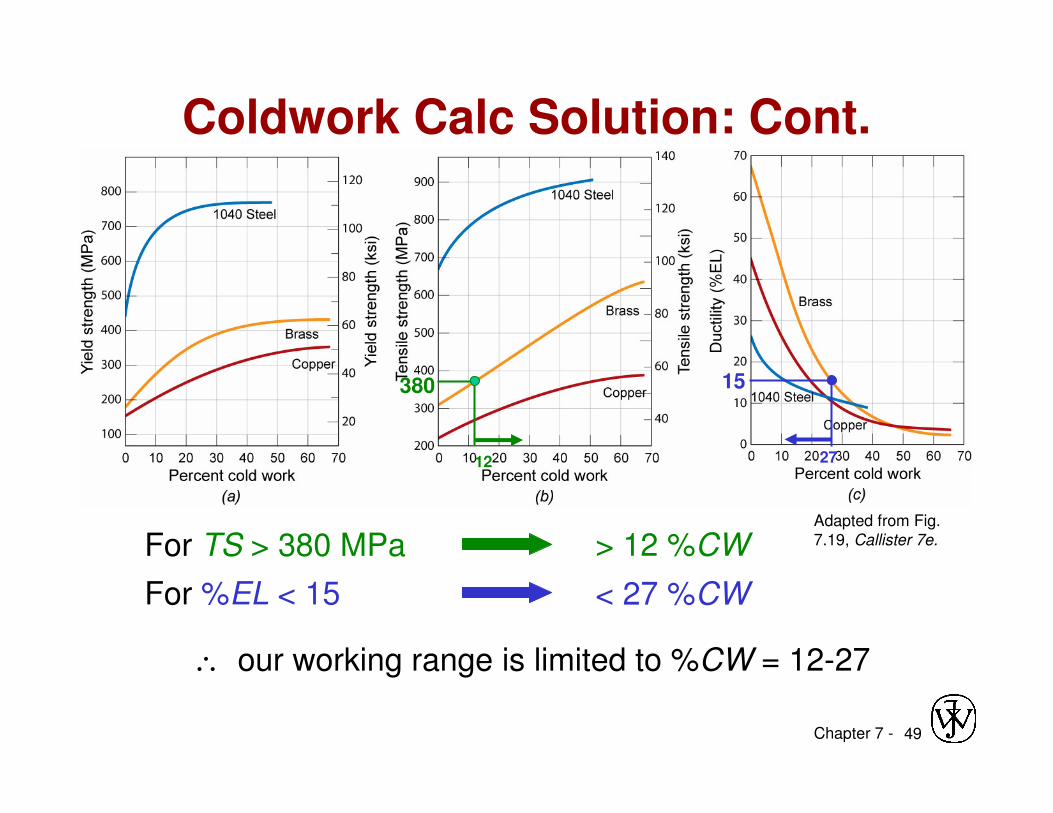
Coldwork Calc Solution: Cont.
Adapted from Fig. 7.19, Callister 7e.
380
12
15
27
For %EL < 15
For TS > 380 MPa > 12 %CW
< 27 %CW
∴ our working range is limited to %CW = 12-27
Chapter 7 - 50
Coldwork Calc Soln: Recrystallization
Cold draw-anneal-cold draw again
• For objective we need a cold work of %CW ≅ 12-27
– We’ll use %CW = 20
• Diameter after first cold draw (before 2nd cold draw)?
– must be calculated as follows:
100
%1 100 1%
2
02
2
2
2
02
2
2 CW
D
Dx
D
DCW ff =−⇒
−=
50
02
2
100
%1
.
f CW
D
D
−= 50
202
100
%1
.
f
CW
DD
−
=⇒⇒⇒⇒
m 3350100
201300
50
021 ..DD
.
f =
−==Intermediate diameter =
Chapter 7 - 51
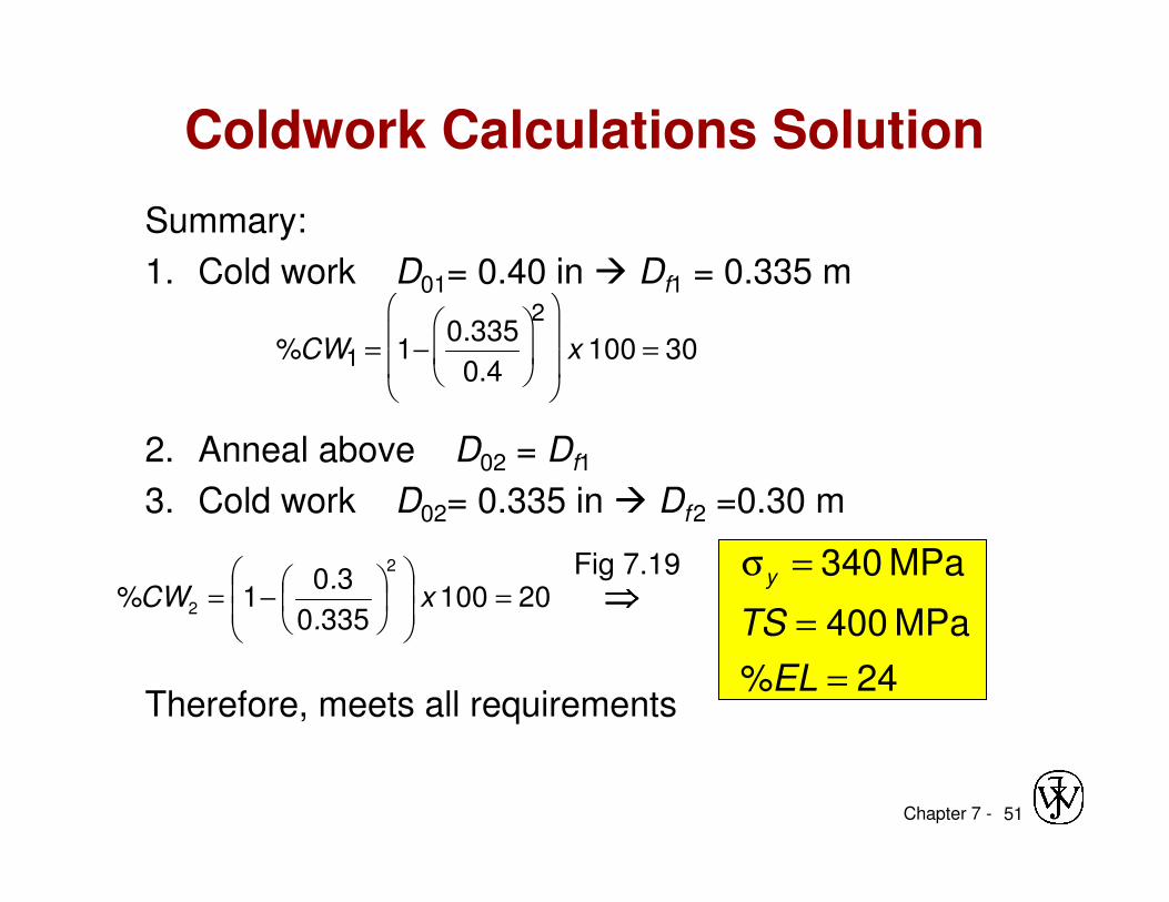
Coldwork Calculations Solution
Summary:
1. Cold work D01= 0.40 in � Df1 = 0.335 m
2. Anneal above D02 = Df1
3. Cold work D02= 0.335 in � Df2 =0.30 m
Therefore, meets all requirements
20100 3350
301%
2
2 =
−= x
.
.CW
24%
MPa 400
MPa 340
=
=
=σ
EL
TS
y⇒⇒⇒⇒
%CW1 = 1−0.335
0.4
2
x 100 = 30
Fig 7.19
Chapter 7 - 52
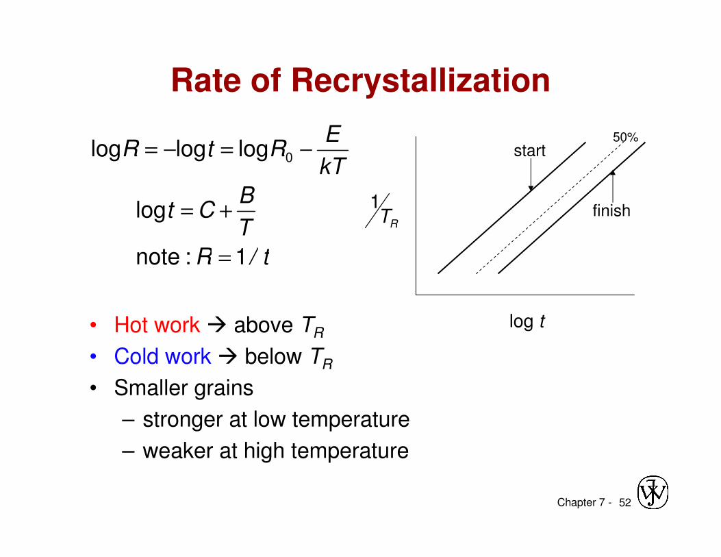
Rate of Recrystallization
• Hot work � above TR
• Cold work � below TR
• Smaller grains
– stronger at low temperature
– weaker at high temperature
t/R
T
BCt
kT
ERtR
1:note
log
logloglog 0
=
+=
−=−=
RT1
log t
start
finish
50%
Chapter 7 - 53
• Dislocations are observed primarily in metalsand alloys.