930.01 INTRODUCTION ............................................................................................................ 930‐1 930.02 LENGTH OF PASSING LANES ......................................................................................... 930‐1 930.03 LANE FREQUENCY ......................................................................................................... 930‐1 930.04 LOCATION GUIDELINES ................................................................................................. 930‐2 930.05 GEOMETRY ................................................................................................................... 930‐4 930.06 GUIDELINES FOR A SYSTEM OF PASSING LANES .......................................................... 930‐5 930.07 ANALYTICAL METHOD FOR A SYSTEM OF PASSING LANES .......................................... 930‐7 930.08 ESTIMATION OF LEVEL OF SERVICE .............................................................................. 930‐8 930.09 WARRANTS ................................................................................................................... 930‐9
940 COMMUNITY MAILBOX PULLOUT
940.01 INTRODUCTION ............................................................................................................ 940‐1 940.02 SITE SELECTION ............................................................................................................. 940‐1 940.03 SITE LAYOUT ................................................................................................................. 940‐1
FIGURE 920.A TYPICAL CLIMBING LANE CONFIGURATION ................................................................. 920‐3
930 PASSING LANE WARRANTS AND DESIGN
FIGURE 930.A TYPICAL PASSING LANE CONFIGURATION .................................................................... 930‐4 FIGURE 930.B ALTERNATIVE CONFIGURATIONS FOR PASSING LANES ............................................... 930‐6 FIGURE 930.C EXAMPLES 1 AND 2 ..................................................................................................... 930‐11 FIGURE 930.D LEVEL TERRAIN GRAPHS ............................................................................................. 930‐12 FIGURE 930.E ROLLING TERRAIN GRAPHS ........................................................................................ 930‐13 FIGURE 930.F MOUNTAINOUS TERRAIN GRAPHS ............................................................................. 930‐14
940 COMMUNITY MAILBOX PULLOUT
FIGURE 940.A MAILBOX PULLOUT SITE LAYOUT ................................................................................. 940‐2
950 COMMERCIAL VEHICLE INSPECTION SITES
FIGURE 950.A MOBILE WEIGH SCALES ................................................................................................ 950‐2
960 TRANSIT FACILITIES
FIGURE 960.A INTERCITY BUS DIMENSIONS ........................................................................................ 960‐2 FIGURE 960.B STANDARD BUS DIMENSIONS ...................................................................................... 960‐2 FIGURE 960.C ARTICULATED BUS DIMENSIONS .................................................................................. 960‐2 FIGURE 960.D RURAL FAR‐SIDE AND NEAR‐SIDE BUS BAYS ................................................................ 960‐4 FIGURE 960.E RURAL MID‐BLOCK SHOULDER BUS BAY ...................................................................... 960‐4 FIGURE 960.F QUEUE JUMPER BUS BAY ............................................................................................. 960‐6
SUPPLEMENT TO TAC GEOMETRIC DESIGN GUIDE BC MoTI MoTI Section 900 TAC Section 3.8 and 3.9
Page 900-iv April, 2019
This page is intentionally left blank
BC MoTI SUPPLEMENT TO TAC GEOMETRIC DESIGN GUIDE MoTI Section 910 TAC Section Not Applicable
April, 2019 Page 910-1
910 SLOW MOVING VEHICLE PULLOUT
910.01 INTRODUCTION Slow Moving Vehicle Pullouts are primarily for “older” 2‐lane highways where passing opportunities are limited and where slow moving vehicles impact the Level of Service and cause unacceptable platooning. These are predominantly summer recreational routes through areas where the cost of conventional passing or climbing lanes would be prohibitive, relative to the benefits. Some jurisdictions call these Turnouts.
910.02 GENERAL When choosing a pullout location, you should balance the passing opportunities for each direction and avoid long no‐passing sections. Signing and pavement marking are in accordance with the Ministry’s Manual of Standard Traffic Signs & Pavement Marking1. Avoid pullouts on downhill sections.
On long winding sections of roadway, locate the pullouts so as to reduce the length of the continuous “No Passing” zones to 15 km or less in mountainous terrain and 10 km or less in level or rolling terrain. Large trucks tend to avoid pullouts, especially on a grade. Pullouts should not be mixed with passing or climbing lanes. No accesses are permitted within pullouts and they should also be avoided opposite the pullout.
Pullouts may also be considered on long uphill grades when a truck climbing lane cannot be built and where speed reductions of at least 20 km/h below the posted or 85th percentile speed are encountered. Refer to TAC Geometric Design Guide for Canadian Roads Figure 3.8.3 Performance Curves for Heavy Trucks, 180 g/W, Decelerations & Accelerations.
910.03 GUIDELINES FOR INSTALLATION
Pullouts should be considered when Level of Service B cannot be maintained due to the presence of slow moving vehicles and insufficient passing opportunities. According to the Highway Capacity Manual (Transportation Research Board, HCM2000 metric edition, Chapter 20), at the Level of Service B/C interface the percent time spent following is 50% on Class I highways, for which efficient mobility is paramount. When the percentage of no passing zones exceeds 60% and the accident history or field observations indicate that there is an excessive amount of dangerous passing manoeuvres due to driver frustration, pullouts should be considered even though Level of Service B is not exceeded during peak hours. (The peak hour in rural situations can be interpreted to be a summer mid‐day hour, typically about the 100th highest hourly volume of the year). Table 910.A gives hourly directional volumes (VAPP), bi‐directional Average Annual Daily Traffic (AADT) and Summer Average Daily Traffic (SADT) with the corresponding distance over which it is likely that queues (delayed vehicles) exceeding 5 vehicles (platoon of 6 vehicles including the slow vehicle) would develop. This represents the spacing of pullouts. Intermediate values can be interpolated.
Table 910.A is derived from a queue catch‐up model provided by ADI Ltd2., using the following assumptions:
The directional volume is the peak hourly flow rate in a 60/40 traffic split.
There are 20% slow moving vehicles (at 20 to 10 km/h below the desired speed of 80 km/h).
The peak hour is 15% of the AADT.
The SADT is 1.5 times the AADT.
SUPPLEMENT TO TAC GEOMETRIC DESIGN GUIDE BC MoTI MoTI Section 910 TAC Section Not Applicable
Page 910-2 April, 2019
Table 910.A Pullout Spacing Recommendations
VAPP Pullout Spacing (km)
(20/10 km/h below desired speed)
SADT AADT
20 30/50 400 250
40 15/25 700 450
60 10/17.5 1050 700
80 7.5/12.5 1350 900
100 6/10 1750 1150
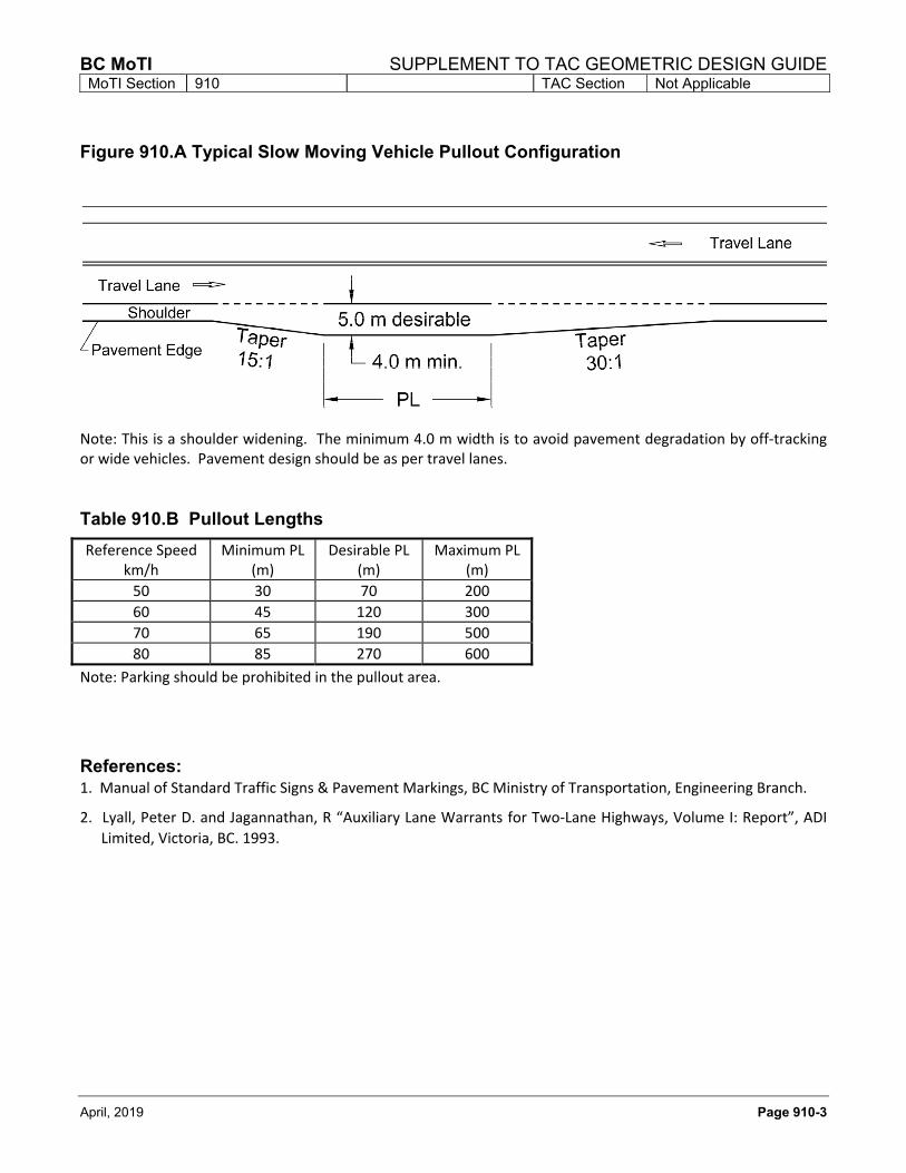
910.04 DESIGN ASSUMPTIONS The following design assumptions were used to obtain the dimensions listed in Table 910.B ‐ Pullout Lengths.
Reference Speed: posted speed or 85th percentile speed, whichever is greater;
Slow moving vehicles are going 20 km/h less than the reference speed;
Minimum PL: The slow moving vehicle (SMV) brakes safely to a stop within the PL;
Desirable PL: The SMV reduces speed to 35 km/h less than the reference speed through the start taper;
Maximum PL: This is the limit above which the pullout becomes a passing lane. The assumption for the maximum length is that the SMV continues at 20 km/h below the reference speed as they drive through the pullout and let 5 vehicles go by. If there are more than 5 vehicles passing, then the SMV’s will have to slow down and come to a stop or merge when safe to do so;
No access within the length of the pullout or opposite the pullout;
Speed of all vehicles other than SMV’s is the reference speed. There are 5 passing vehicles;
Stopping Sight Distance for the reference speed should be available through the entire length.
BC MoTI SUPPLEMENT TO TAC GEOMETRIC DESIGN GUIDE MoTI Section 910 TAC Section Not Applicable
Note: This is a shoulder widening. The minimum 4.0 m width is to avoid pavement degradation by off‐tracking or wide vehicles. Pavement design should be as per travel lanes.
Table 910.B Pullout Lengths
Reference Speed km/h
Minimum PL (m)
Desirable PL (m)
Maximum PL (m)
50 30 70 200
60 45 120 300
70 65 190 500
80 85 270 600
Note: Parking should be prohibited in the pullout area.
References: 1. Manual of Standard Traffic Signs & Pavement Markings, BC Ministry of Transportation, Engineering Branch.
2. Lyall, Peter D. and Jagannathan, R “Auxiliary Lane Warrants for Two‐Lane Highways, Volume I: Report”, ADI
Limited, Victoria, BC. 1993.
SUPPLEMENT TO TAC GEOMETRIC DESIGN GUIDE BC MoTI MoTI Section 910 TAC Section Not Applicable
Page 910-4 April, 2019
This page is intentionally left blank
BC MoTI SUPPLEMENT TO TAC GEOMETRIC DESIGN GUIDE MoTI Section 920 TAC Section 3.8
April, 2019 Page 920-1
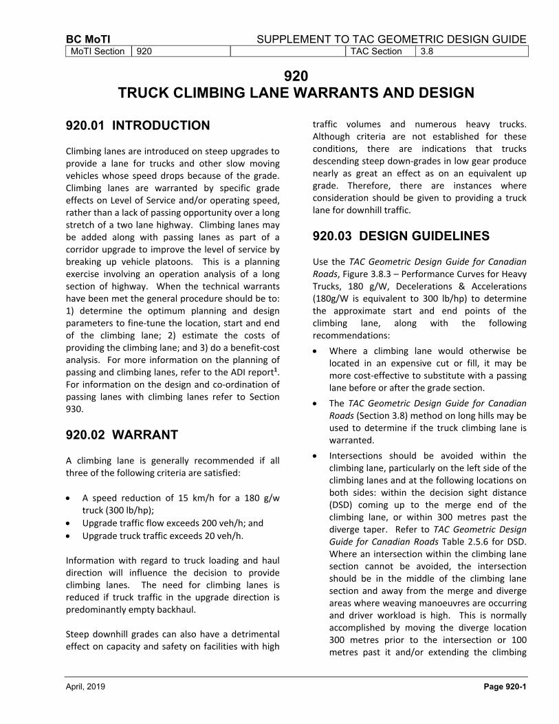
920 TRUCK CLIMBING LANE WARRANTS AND DESIGN
920.01 INTRODUCTION Climbing lanes are introduced on steep upgrades to provide a lane for trucks and other slow moving vehicles whose speed drops because of the grade. Climbing lanes are warranted by specific grade effects on Level of Service and/or operating speed, rather than a lack of passing opportunity over a long stretch of a two lane highway. Climbing lanes may be added along with passing lanes as part of a corridor upgrade to improve the level of service by breaking up vehicle platoons. This is a planning exercise involving an operation analysis of a long section of highway. When the technical warrants have been met the general procedure should be to: 1) determine the optimum planning and design parameters to fine‐tune the location, start and end of the climbing lane; 2) estimate the costs of providing the climbing lane; and 3) do a benefit‐cost analysis. For more information on the planning of passing and climbing lanes, refer to the ADI report1. For information on the design and co‐ordination of passing lanes with climbing lanes refer to Section 930.
920.02 WARRANT A climbing lane is generally recommended if all three of the following criteria are satisfied:
A speed reduction of 15 km/h for a 180 g/w truck (300 lb/hp);
Upgrade traffic flow exceeds 200 veh/h; and
Upgrade truck traffic exceeds 20 veh/h. Information with regard to truck loading and haul direction will influence the decision to provide climbing lanes. The need for climbing lanes is reduced if truck traffic in the upgrade direction is predominantly empty backhaul. Steep downhill grades can also have a detrimental effect on capacity and safety on facilities with high
traffic volumes and numerous heavy trucks. Although criteria are not established for these conditions, there are indications that trucks descending steep down‐grades in low gear produce nearly as great an effect as on an equivalent up grade. Therefore, there are instances where consideration should be given to providing a truck lane for downhill traffic.
920.03 DESIGN GUIDELINES Use the TAC Geometric Design Guide for Canadian Roads, Figure 3.8.3 – Performance Curves for Heavy Trucks, 180 g/W, Decelerations & Accelerations (180g/W is equivalent to 300 lb/hp) to determine the approximate start and end points of the climbing lane, along with the following recommendations:
Where a climbing lane would otherwise be located in an expensive cut or fill, it may be more cost‐effective to substitute with a passing lane before or after the grade section.
The TAC Geometric Design Guide for Canadian Roads (Section 3.8) method on long hills may be used to determine if the truck climbing lane is warranted.
Intersections should be avoided within the climbing lane, particularly on the left side of the climbing lanes and at the following locations on both sides: within the decision sight distance (DSD) coming up to the merge end of the climbing lane, or within 300 metres past the diverge taper. Refer to TAC Geometric Design Guide for Canadian Roads Table 2.5.6 for DSD. Where an intersection within the climbing lane section cannot be avoided, the intersection should be in the middle of the climbing lane section and away from the merge and diverge areas where weaving manoeuvres are occurring and driver workload is high. This is normally accomplished by moving the diverge location 300 metres prior to the intersection or 100 metres past it and/or extending the climbing
SUPPLEMENT TO TAC GEOMETRIC DESIGN GUIDE BC MoTI MoTI Section 920 TAC Section 3.8
Page 920-2 April, 2019
lane merge beyond the intersection for a distance equivalent to the DSD. Where an intersection on the left side cannot be avoided, it is desirable to include a left turn lane since a stopped left turn vehicle in the left lane represents a high hazard to overtaking traffic.
Where traffic volumes are moderate to high (SADT greater than 1000 veh/day), driver reaction to short climbing lanes is generally negative. The minimum climbing lane should allow about 30 seconds of passing opportunity, which is equivalent to 700 m at 80 km/h. At traffic volumes lower than 1000 SADT a minimum climbing length of 500 m is recommended.
The minimum climbing lane width is 3.6 m. The shoulder adjacent to the climbing lane may be up to 1.0 m less than the shoulder adjacent to the 2‐lane section, but no less than 1.5 m. If this is part of a staged development to 4‐lane, the climbing lane shoulder width should match the ultimate 4‐lane shoulder width.
The diverge taper, merge taper and signing shall be done in accordance with the Ministry’s Manual of Standard Traffic Signs & Pavement Markings2. Advance signing of a climbing lane ahead should be considered to encourage drivers to wait, rather than perform a hazardous passing manoeuvre.
DSD ahead to the middle of the diverge taper is desirable from an operation perspective, but not critical from a safety perspective. Good sight distance means that the climbing lane will be used more effectively since traffic can see the climbing lane coming, encouraging earlier separation of slow and fast moving vehicles into their respective lanes.
Sight distance from the start of the merge taper ahead, should be equal to the minimum barrier line passing sight distance in the Manual of Standard Traffic Signs & Pavement Markings. This allows for a pass initiated at the end of the climbing lane to be safely completed or aborted if the overtaking vehicle is forced into the opposing lane.
920.04 MULTILANE HIGHWAYS Climbing lanes on multilane highways also serve to separate slower vehicles from faster ones and thereby help maintain a high level of service on long grades. The analysis and determination if multilane climbing lanes are warranted is a Planning function that follows the methodology outline in page 20‐28 of the Highway Capacity Manual, TRB (HCM 2000)3. A drop of one level of service or a speed reduction of 15 km/h on the upgrade is an indicator that a climbing lane may be required. This should be verified with an operational analysis of the approach segment and the upgrade. Should the analysis indicate that an additional lane is required on the upgrade, a climbing lane is warranted. The location and design of a climbing lane on multilane highways follows the same Guidelines as for two lane. The corridor strategy is determined by the Ministry’s regional planning staff. Detailed design rests with the Regional Design staff or design consultant. Close co‐operation is required between planning and design as a team to ensure that the planning objectives are maintained as the design options are evaluated and selected. This close co‐operation will improve the likelihood of funding approval.
BC MoTI SUPPLEMENT TO TAC GEOMETRIC DESIGN GUIDE MoTI Section 920 TAC Section 3.8
April, 2019 Page 920-3
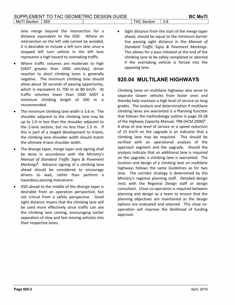
Figure 920.A Typical Climbing Lane Configuration
See the Ministry’s Manual of Standard Traffic Signs & Pavement Markings2 for additional information on Sign Placement and opposing lane passing restriction criteria.
References: 1. Lyall, Peter D. and Jagannathan, R “Auxiliary Lane Warrants for Two‐Lane Highways, Volume I: Report”, ADI
Limited, Victoria, BC. 1993.
2. Manual of Standard Traffic Signs & Pavement Markings, BC Ministry of Transportation, Engineering Branch.
3. Highway Capacity Manual, Transportation Research Board (HCM2000 ‐ Metric).
SUPPLEMENT TO TAC GEOMETRIC DESIGN GUIDE BC MoTI MoTI Section 920 TAC Section 3.8
Page 920-4 April, 2019
This page is intentionally left blank
BC MoTI SUPPLEMENT TO TAC GEOMETRIC DESIGN GUIDE MoTI Section 930 TAC Section 3.9
April, 2019 Page 930-1
930 PASSING LANE WARRANTS AND DESIGN
930.01 INTRODUCTION Passing lanes are auxiliary lanes designed to improve passing opportunity on two lane highways except where an auxiliary lane is warranted by grades alone, in which cases climbing lanes are used (refer to Section 920.02).
Regional Planning performs corridor reviews for the purpose of maintaining or upgrading the quality of the provincial road network. Passing lanes are used to upgrade the level of service on a two lane highway where four laning is not contemplated at least at this stage of the planning. When the technical warrants have been met the general procedure should be to: 1) determine the optimum planning and design parameters; 2) estimate the costs of providing the passing lane; and 3) do a benefit‐cost analysis. At the detailed design stage, design options are further analyzed for cost and operational efficiency. During this fine tuning exercise, the co‐operation between regional planning staff and the designer is crucial to strike a balance between the planning objectives and the design/construction/operation realities.
Passing opportunity on a two lane highway is mainly governed by sight distance and traffic in the opposing direction. When there is insufficient passing opportunity, queues or platoons begin to build up, increasing driver frustration and workload which leads to an increase in risk taking manoeuvres and serious, high speed accidents. Conditions which lead to this type of platoon buildup requiring the consideration of auxiliary passing lanes include:
long stretches with no‐passing opportunities;
circuitous alignment in rolling or mountainous terrain;
sparsely developed local street network thereby forcing slow moving traffic to use the highway;
a high percentage of long distance, high speed trips mixed with slow moving vehicles;
a significant percentage of slow moving vehicles (heavy trucks & RVs) generating platoons; and
traffic volumes high enough to restrict passing but too low to warrant widening to four lanes.
930.02 LENGTH OF PASSING LANES
Analysis conducted by Harwood1 on existing U.S. passing lanes shows that the most cost effective length for passing lanes increases with flow rate as follows:
Table 930.A Passing Lane Lengths
One‐way Flow Optimal Passing Lane
Rate (vph) Length (km)
100 0.8
200 0.8 ‐ 1.2
400 1.2 ‐ 1.6
700 1.6 ‐ 3.2
Some jurisdictions use a consistent 2.0 km length regardless of traffic volume. Although this is desirable, it is often not possible in BC due to roadside development or terrain constraints. It is recommended that 2.0 km be used where possible but shorter passing lanes be considered where necessary. The lane should allow for at least 30 seconds of passing opportunity in order to disperse platoons of 4 to 6 vehicles.
930.03 LANE FREQUENCY Passing lane frequency (LF) is the distance from the start of one passing lane to the start of the next downstream passing lane in the same direction of travel. Passing lane spacing is the distance from the end of one auxiliary lane to the start of the next in the same direction.
Establishing the need for passing lane frequency is helpful prior to determining potential locations. It
SUPPLEMENT TO TAC GEOMETRIC DESIGN GUIDE BC MoTI MoTI Section 930 TAC Section 3.9
Page 930-2 April, 2019
is also an indication of how practical it is to achieve desired levels of service. If passing lanes are required at very short intervals to maintain a desired level of service, it is an indication that alternatives to passing lanes should be considered.
The desired lane frequency varies depending on:
passing lane length;
traffic volumes;
traffic composition; and
downstream passing opportunities. Following are some typical passing lane spacings (end of one lane to the start of the next) given as a function of AADT:
Table 930.B PASSING LANE SPACINGS
Spacing between
AADT passing lanes (km)
1001 ‐3000 9.6
3001 ‐ 5000 8.0
5001 ‐ 7000 6.4
7001 ‐ 9000 4.4
>9000 4.0
Notes:
1. Minimum spacing between auxiliary passing lanes is a function of the time it takes for platoons to re‐form. This is the basis of Table 930.B. The individual passing lane length includes tapers.
2. Low volume roads which may not warrant passing lanes based on the above criteria may still require some passing opportunities in the form of passing lanes or slow moving vehicle pullouts (see Section 910) if the highway has extended no passing zones. As a guideline, vehicles should have either a passing zone or a passing lane or slow moving vehicle pullout every 10 minutes to prevent drivers from overtaking in a no passing zone. Passing Lanes are auxiliary facilities; passing zones are locations where sight distance permits overtaking by use of the opposing direction lane and are marked with dashed lines.
930.04 LOCATION GUIDELINES Locate individual passing lanes to ensure maximum safety and operational benefits from the investment. The designer should strive to follow these guidelines:
Locate passing lanes where the minimum feasible construction cost occurs (avoid large cuts and fills, particularly in rock), subject to other constraints.
Intersections should be avoided within the passing lane, particularly on the left side and in the vicinity of the merge and diverge tapers. Avoid intersections within the decision sight distance (DSD) upstream of the merge end of the passing lane, or within 300 metres downstream of the diverge taper. Refer to TAC Geometric Design Guide for Canadian Roads Table 2.5.6 for DSD.
When an intersection in the passing lane section cannot be avoided, the intersection should be in the middle of the passing lane section away from the merge and diverge areas where other weaving manoeuvres are occurring and driver workload is high. The intersection should have a separate left turn lane regardless of traffic volume since a stopped left turn vehicle in the passing lane represents a high hazard to overtaking traffic. “T” Intersections on the passing lane side are more desirable than intersections on the opposing side; they do not generate left turn movements to or from the fast lane.
Minimum DSD ahead to the middle of the diverge taper is desirable from an operation perspective, but not critical from a safety perspective. Good sight distance means the passing lane will be used more effectively since traffic can see the passing lane coming, encouraging earlier separation of slow and fast moving vehicles into their respective lanes.
The sight distance to the middle of the merge taper should be at least equal to the minimum decision sight distance to allow for an overtaking vehicle to either complete a pass or adjust speed to that of the slower vehicle. The
BC MoTI SUPPLEMENT TO TAC GEOMETRIC DESIGN GUIDE MoTI Section 930 TAC Section 3.9
April, 2019 Page 930-3
termination point should be visible to approaching traffic and allow a smooth and safe merge between slow and fast vehicle streams.
Sight distance from the start of the merge taper ahead, should be equal to the minimum barrier line passing sight distance in the Ministry’s Manual of Standard Traffic Signs & Pavement Markings2. This allows for a pass initiated at the end of the climbing lane to be safely completed if the overtaking vehicle is forced into the opposing lane.
Note that Barrier Line Sight distance is not the same as design passing sight distance. The former includes distance traveled by the overtaking vehicle while encroaching on the opposing lane plus half the distance traveled by an opposing vehicle while design passing sight distance includes barrier line sight distance plus a component for the initial decision/acceleration phase.
Where possible, develop the diverge taper around a long flat horizontal curve. This facilitates separation of the fast and slow streams of traffic and does not take away from any existing passing opportunity. Left hand curves offer the overtaking drivers a better view into the passing lane around the impeding vehicle. Right hand curves do not have the same sight distance but do lead slower vehicles naturally into the slow lane since the normal driving tendency is to steer to the inside of the curve.
Passing lanes after a long no‐passing zone are more effective than one constructed before it. The upstream no passing zone causes platoon buildup prior to the passing lane and downstream passing opportunities help platoons to remain dispersed longer.
The addition of passing lanes should not be detrimental to the passing opportunities for the opposing direction. Avoid passing lanes in locations where passing is already permitted by markings, unless the passing opportunity is significantly lessened due to high opposing volumes. The location of the passing lane should appear logical to the driver; its value is
more obvious to the driver at locations where normal passing sight distance is restricted.
Passing lanes are less effective where passing opportunity is already high. Horizontal curves and upgrades where no passing prevails are good locations.
Passing lanes provide little benefit when constructed on long tangent sections and on long downgrades with low traffic volumes (AADT<3000) and low percentages of heavy trucks. In these cases, platoon leaders on such sections tend to speed up or not pull over, limiting the benefits from the passing lane.
Passing lanes should be placed leading away from rather than into areas of traffic congestion. When placed on the outbound direction from a town (or development) they are helpful in dispersing platoons which have built up within the town. Passing lanes on the inbound direction just before a town are less effective and may also be undesirable by encouraging high speed passing just before a reduced speed zone.
Avoid passing lanes near four‐lane highway sections which effectively serve the same purpose.
Passing lanes in the uphill direction of a highway on a sustained grade section are more effective than one on a level grade because of the greater speed differentials.
Reduced speed (sub standard) curves, should be avoided in passing lane sections since there is a tendency for traffic to speed up in these sections. Horizontal curves should be at least equal to the minimum radius for the design speed of the highway (see Section 330).
Physical constraints such as bridges and culverts should be avoided due to the additional cost and the lack of a continuous shoulder through the passing lane section.
The total length of all auxiliary lanes in one direction should be less than half the roadway section length. Also, the passing opportunity should be equal in both directions.
SUPPLEMENT TO TAC GEOMETRIC DESIGN GUIDE BC MoTI MoTI Section 930 TAC Section 3.9
Page 930-4 April, 2019
930.05 GEOMETRY Geometric design standards should be consistent with the following MoTI guidelines and practice:
The desirable length of passing lanes is between 1.5 km and 2.0 km. This range is long enough to be adequate for dispersing queues while still being short enough to be cost effective.
The minimum lane width is 3.6 m. The shoulder adjacent to the passing lane should desirably be the same as the shoulder adjacent to the 2‐lane section. If the shoulder must be reduced, the reduction should not exceed 1.0 m and the remaining width should be no less than 1.5 m.
If this is part of a staged development to 4‐lane, the passing lane shoulder width should match the ultimate 4‐lane shoulder width.
The diverge taper, merge taper and signing shall be done in accordance with the Ministry’s Manual of Standard Traffic Signs & Pavement Markings2. Advance signing (I‐082‐1 and I‐082‐2 in Manual of Standard Traffic Signs & Pavement Markings) 2 km ahead of a passing lane should be used to advise drivers to wait, rather than perform a hazardous pass. Benefit‐cost analysis assumes a 3% reduction in accidents for this 2 km, due to the advanced signing alone.
Figure 930.A Typical Passing Lane Configuration
Table 930.C Merge Taper Lengths
Posted Speed Limit (km/h)
Merge Taper (m)
50 110
60 130
70 150
80 175
90 195
100 215
110 240
See the Ministry’s Manual of Standard Traffic Signs & Pavement Markings2 for additional information on Sign Placement and opposing lane passing restriction criteria.
BC MoTI SUPPLEMENT TO TAC GEOMETRIC DESIGN GUIDE MoTI Section 930 TAC Section 3.9
April, 2019 Page 930-5
930.06 GUIDELINES FOR A SYSTEM OF PASSING LANES
On highways that are not constrained by development or terrain, there may be several sections that satisfy some or all of the location guidelines. The selection of an overall workable combination of passing lanes for both directions of traffic from these sections is an iterative process. The design options should be tested for their overall operational effectiveness as a system. Figure 930.B shows schematically some ways to combine passing lanes in both directions as a unified system. Following is a suggested method to develop optional arrangements for review as a system:
Initially, identify all potential passing lane locations in both directions, irrespective of desired lane frequency.
With the climbing lane locations fixed and potential passing lane locations identified, select combinations of auxiliary lanes at (or close to) the desired passing lane frequency taking into account any existing auxiliary lanes. The frequency should be no less than four kilometres (including the length of auxiliary lane) apart.
It is generally desirable to stagger opposing direction passing lanes to avoid the mistaken impression of a 4 lane highway. Some overlap is acceptable. Short four‐lane sections are appropriate in valley sections where there is no other option or where the whole section would form part of an ultimate four‐laning scheme.
Do not overlap opposing auxiliary lanes through major intersections. This would require additional turning lanes resulting in a five‐lane cross section (two‐lane highway, two auxiliary lanes, and one turning lane) in an otherwise two‐lane highway template. These types of intersections are confusing to through traffic and are also very difficult for left turn minor road traffic to negotiate due to number of conflicting lane movements on the major road.
Where possible, place opposing auxiliary lanes tail‐to‐tail rather than head‐to‐head (the tail is the diverge). In the tail‐to‐tail configuration, the opposing direction auxiliary lane restricts advancing passing maneuvers upstream of the advancing lane rather than downstream. The head‐to‐head configuration may also be a safety problem in winter time when pavement markings are hidden by snow resulting in vehicles traveling in the oncoming passing lane.
When dealing with high traffic volumes and limited passing opportunities, avoid placing a single auxiliary lane in a long section favoring one direction of traffic at the expense of the opposing traffic. This may cause a race‐track effect, where aggressive drivers tend to speed up to make use of the only passing opportunity available. Staged development of an auxiliary lane system may result in this situation, but it should be avoided in the ultimate development of the auxiliary lane system.
Try to achieve balanced overall passing opportunities for both directions.
SUPPLEMENT TO TAC GEOMETRIC DESIGN GUIDE BC MoTI MoTI Section 930 TAC Section 3.9
Page 930-6 April, 2019
Figure 930.B Alternative Configurations for Passing Lanes:
(source: Overtaking Lane Practice in Canada and Australia3)
BC MoTI SUPPLEMENT TO TAC GEOMETRIC DESIGN GUIDE MoTI Section 930 TAC Section 3.9
April, 2019 Page 930-7
930.07 ANALYTICAL METHOD FOR A SYSTEM OF PASSING LANES
The passing lane analysis, which follows is performed after climbing lane warrants have been considered. This is an estimation of level of service for the existing highway at design year using regression equations. These equations predict the percent following as a function of Assured Passing Opportunity (APO). The regression equations were derived from TRARR simulations.
The APO factor is defined as the percentage of time when one vehicle can safely pass another without restriction either by inadequate sight distance or the presence of opposing traffic. It is often used as the level of service measure for passing lane studies since it relates directly to the role of passing zones in reducing vehicle platoons. APO is calculated separately for each direction as:
APO = (PZL/L)*HF
where
APO = Assured Passing Opportunity (%)
PZL = Passing Zone Length (km) HF = Headway Factor (%) L = Length of the highway
segment (km)
PZL for a direction is the length of highway within a highway segment L which has passing zones (broken lines) and can be determined through viewing the ministry’s photolog imaging system (or other mapping services) on the Internet. To obtain access to the photolog Internet site, contact the Data Program Coordinator, Highway Planning Branch, Victoria. For highways which have not yet been constructed, PZL must be estimated from plans and profiles using the Manual of Standard Traffic Signs & Pavement Markings2 standards for barrier line passing sight distance. This dimension is different from Design Passing Sight Distance and is defined in the Manual of Standard Traffic Signs & Pavement Markings.
Headway factor (HF) is the percentage of time when headway between successive vehicles in the opposing lane is greater than 25 seconds. The 25 seconds criterion is based on the time taken for an overtaking vehicle for the initial maneuver (5 sec.) plus encroachment on the opposing lane (10 sec.) plus 5 seconds for an opposing vehicle appearing half way through the overtaking vehicle encroachment phase plus a 5 second clearance to the opposing vehicle at the completion of the pass.
Headway factor is approximated as:
HF = exp(‐k * VOPP)
where VOPP is the volume of opposing direction traffic (veh/h) and k is a constant dependent on the terrain. For a given opposing volume, the percentage of time with gaps in the opposing direction greater than 25 seconds is typically higher for mountainous terrain than for a level terrain. In mountainous terrain, a higher proportion of vehicles will be in platoons; therefore, long gaps are introduced between platoons.
The following k constants are recommended:
‐ 0.002 for mountainous terrain (observations on Highway 99 by ADI Limited4, and Alberta data),
‐ 0.004 for rolling terrain (Ontario), ‐ 0.006 for level terrain or highways with high
access volumes (observations in Victoria, BC by ADI Limited).
Planners may wish to use the actual headway factors, measured in the field, for a given highway rather than an estimate based on the k constant. Where there is a high percentage of PZL, the calculated percentage following becomes more sensitive to the choice of k constants. Varying the k constant by 0.001 typically changes the percent following by about 5% (15% is equal to one level of service).
HF may be estimated from some of the Province's Weigh‐in‐Motion stations or manually by measuring the opposing traffic volume (veh/h) and gaps greater than 25 seconds for groups of about 100 vehicles. The headway factor at the observed flow rate is calculated as follows:
SUPPLEMENT TO TAC GEOMETRIC DESIGN GUIDE BC MoTI MoTI Section 930 TAC Section 3.9
Page 930-8 April, 2019
T
25N ‐ sec) 25 > (gaps = HF
Where
T = Total observation time (seconds)
N = Number of gaps >25 seconds observed from a stationary point
The main objective is to relate the APO and the total auxiliary passing lane length (ALL) to the percentage of vehicles following (%FOLL) and thus, the level of service (LOS).
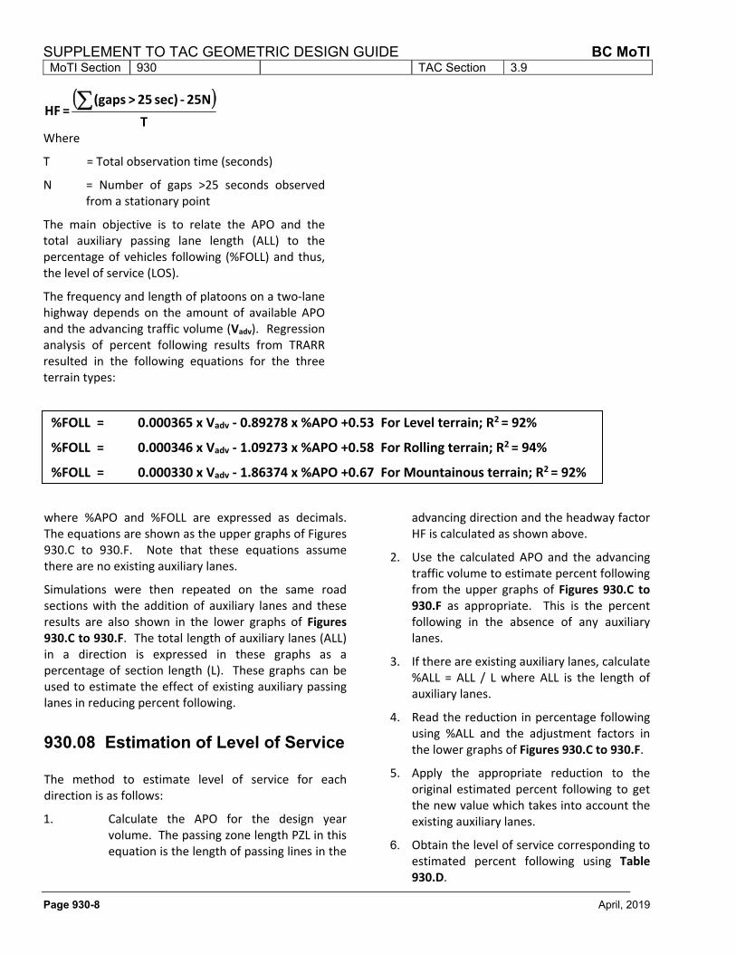
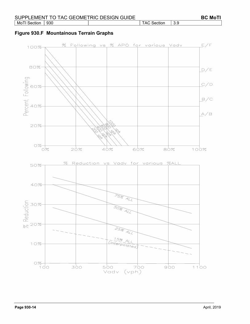
The frequency and length of platoons on a two‐lane highway depends on the amount of available APO and the advancing traffic volume (Vadv). Regression analysis of percent following results from TRARR resulted in the following equations for the three terrain types:
%FOLL = 0.000365 x Vadv ‐ 0.89278 x %APO +0.53 For Level terrain; R2 = 92%
%FOLL = 0.000346 x Vadv ‐ 1.09273 x %APO +0.58 For Rolling terrain; R2 = 94%
%FOLL = 0.000330 x Vadv ‐ 1.86374 x %APO +0.67 For Mountainous terrain; R2 = 92%
where %APO and %FOLL are expressed as decimals. The equations are shown as the upper graphs of Figures 930.C to 930.F. Note that these equations assume there are no existing auxiliary lanes.
Simulations were then repeated on the same road sections with the addition of auxiliary lanes and these results are also shown in the lower graphs of Figures 930.C to 930.F. The total length of auxiliary lanes (ALL) in a direction is expressed in these graphs as a percentage of section length (L). These graphs can be used to estimate the effect of existing auxiliary passing lanes in reducing percent following.
930.08 Estimation of Level of Service
The method to estimate level of service for each direction is as follows:
1. Calculate the APO for the design year volume. The passing zone length PZL in this equation is the length of passing lines in the
advancing direction and the headway factor HF is calculated as shown above.
2. Use the calculated APO and the advancing traffic volume to estimate percent following from the upper graphs of Figures 930.C to 930.F as appropriate. This is the percent following in the absence of any auxiliary lanes.
3. If there are existing auxiliary lanes, calculate %ALL = ALL / L where ALL is the length of auxiliary lanes.
4. Read the reduction in percentage following using %ALL and the adjustment factors in the lower graphs of Figures 930.C to 930.F.
5. Apply the appropriate reduction to the original estimated percent following to get the new value which takes into account the existing auxiliary lanes.
6. Obtain the level of service corresponding to estimated percent following using Table 930.D.
BC MoTI SUPPLEMENT TO TAC GEOMETRIC DESIGN GUIDE MoTI Section 930 TAC Section 3.9
April, 2019 Page 930-9
930.09 Warrants
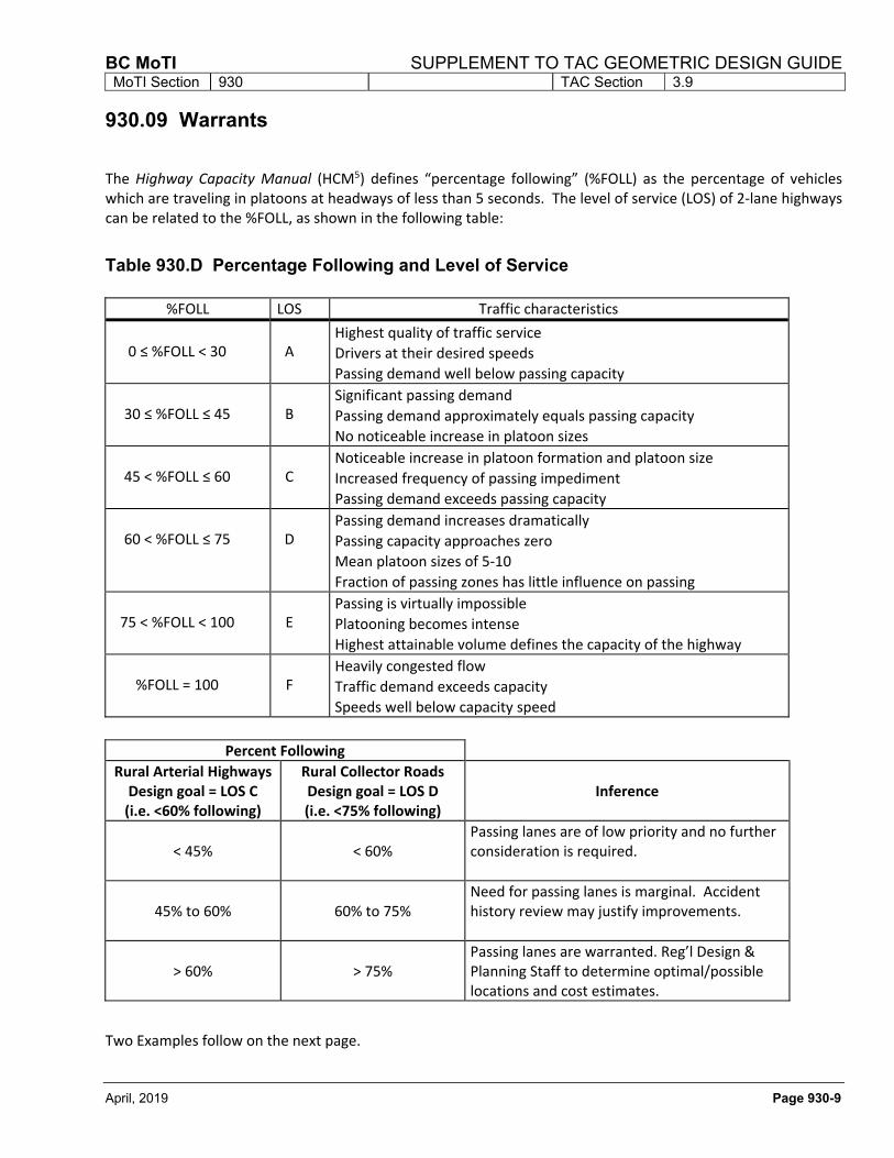
The Highway Capacity Manual (HCM5) defines “percentage following” (%FOLL) as the percentage of vehicles which are traveling in platoons at headways of less than 5 seconds. The level of service (LOS) of 2‐lane highways can be related to the %FOLL, as shown in the following table:
Table 930.D Percentage Following and Level of Service
%FOLL LOS Traffic characteristics
0 ≤ %FOLL < 30
A
Highest quality of traffic service
Drivers at their desired speeds
Passing demand well below passing capacity
30 ≤ %FOLL ≤ 45
B
Significant passing demand
Passing demand approximately equals passing capacity
No noticeable increase in platoon sizes
45 < %FOLL ≤ 60
C
Noticeable increase in platoon formation and platoon size
Increased frequency of passing impediment
Passing demand exceeds passing capacity
60 < %FOLL ≤ 75
D
Passing demand increases dramatically
Passing capacity approaches zero
Mean platoon sizes of 5‐10
Fraction of passing zones has little influence on passing
75 < %FOLL < 100
E
Passing is virtually impossible
Platooning becomes intense
Highest attainable volume defines the capacity of the highway
%FOLL = 100
F
Heavily congested flow
Traffic demand exceeds capacity
Speeds well below capacity speed
Percent Following
Rural Arterial Highways Design goal = LOS C (i.e. <60% following)
Rural Collector Roads Design goal = LOS D (i.e. <75% following)
Inference
< 45%
< 60%
Passing lanes are of low priority and no further consideration is required.
45% to 60%
60% to 75%
Need for passing lanes is marginal. Accident history review may justify improvements.
> 60%
> 75%
Passing lanes are warranted. Reg’l Design & Planning Staff to determine optimal/possible locations and cost estimates.
Two Examples follow on the next page.
SUPPLEMENT TO TAC GEOMETRIC DESIGN GUIDE BC MoTI MoTI Section 930 TAC Section 3.9
Page 930-10 April, 2019
Example 1 Given: Length of study area, L = 40 km Mountainous terrain, no auxiliary lanes, 1.4 km of passing zones DHV =562 vph, 85:15 split, Vadv = 478 vph, VOPP = 84 vph Design goal of LOS C/D interface (60% Foll)
Calculate: Headway Factor
HF = e‐0.002VOPP = e‐0.002*84 = 0.845 PZL = 1.4 km (APO) = (PZL/L) x HF = (1.4/40) x 0.845 = 0.030
From the mountainous terrain equation: %FOLL = 0.000330(Vadv) ‐ 1.86374(APO) + 0.67 = 0.000330(478) ‐ 1.86374(0.030) + 0.67 = 0.77 or 77%
Since %FOLL at the design goal is 60%, auxiliary lanes are required to reduce percent following from 0.77 to 0.60; i.e. by [(0.77‐0.60)/0.77] = 22%.
From Figure 930.F, a 22% reduction in percent following at a Vadv of 478 vph requires about 28% ALL which corresponds to 0.28 x 40 = 11.2 km of passing lanes.
Assuming a typical passing lane length of 2.0 km the desired lane frequency is:
LF = L/(ALL/2.0) = 40/(11.2/2) = 7.1 km
The upper graph of Figure 930.C shows the use of Figure
930.F for this example.
Example 2 Given: Length of study area, L = 40 km Mountainous terrain, 7.7 km of auxiliary lanes, 1.4 km of passing zones DHV =758 vph, 85:15 split, Vadv =644 vph, VOPP = 114 vph Design goal of LOS C/D interface (60% Foll)
Calculate: Headway Factor
HF = e‐0.002VOPP = e‐0.002*114 = 0.796 PZL = 1.4 km (APO) = (PZL/L) x HF = (1.4/40) x 0.796 = 0.028
From the mountainous terrain equation: %FOLL = 0.000330(Vadv) ‐ 1.86374(APO) + 0.67 = 0.000330(644) ‐ 1.86374(0.028) + 0.67 = 0.83 or 83%
Existing Percentage Auxiliary Lane Length (%ALL) = 7.7/40 = 19%
From the lower graph of Figure 930.F, we get:
25%ALL 17% reduction in percent following
0%ALL 0% reduction in percent following
Therefore, from interpolation:
19%ALL 19x17/25 = 13% reduction in percent following (Interpolated)
Percent following = 0.83 X (1 ‐ 0.13) = 72%
Since %FOLL at the design goal is 60%, additional auxiliary lanes are required to reduce percent following from 0.72 to 0.60; i.e. by [(0.72‐0.60)/0.72] = 17%.
From Figure 930.F, a 17% reduction in percent following at a Vadv of 644 vph requires 25% ALL which corresponds to 0.25 x 40 = 10.0 km of passing lanes, in addition to existing 7.7 km of passing lanes.
Assuming a typical passing lane length of 2.0 km the desired lane frequency is:
LF = L/(ALL/2.0) = 40/(17.7/2) = 4.5 km The lower graph of Figure 930.C shows the use of Figure 930.F for this example.
BC MoTI SUPPLEMENT TO TAC GEOMETRIC DESIGN GUIDE MoTI Section 930 TAC Section 3.9
April, 2019 Page 930-11
Figure 930.C Examples 1 and 2
SUPPLEMENT TO TAC GEOMETRIC DESIGN GUIDE BC MoTI MoTI Section 930 TAC Section 3.9
Page 930-12 April, 2019
Figure 930.D Level Terrain Graphs
BC MoTI SUPPLEMENT TO TAC GEOMETRIC DESIGN GUIDE MoTI Section 930 TAC Section 3.9
April, 2019 Page 930-13
Figure 930.E Rolling Terrain Graphs
SUPPLEMENT TO TAC GEOMETRIC DESIGN GUIDE BC MoTI MoTI Section 930 TAC Section 3.9
Page 930-14 April, 2019
Figure 930.F Mountainous Terrain Graphs
BC MoTI SUPPLEMENT TO TAC GEOMETRIC DESIGN GUIDE MoTI Section 930 TAC Section 3.9
April, 2019 Page 930-15
References: 1. Harwood D.W., Hoban C.J., Warren D., “Effective Use of Passing Lanes on Two‐Lane Highways”,
Transportation Research Record 1195, Transportation Research Board, 1988. 2. “Manual of Standard Traffic Signs & Pavement Markings”, BC Ministry of Transportation, Engineering
Branch.
3. C. J. Hoban and J. F. Morrall, “Overtaking Lane Practice in Canada and Australia”, Research Report No. ARR
144, Australian Road Research Board, 1985. 4. Lyall, Peter D. and Jagannathan, R “Auxiliary Lane Warrants for Two‐Lane Highways, Volume I: Report”, ADI
SUPPLEMENT TO TAC GEOMETRIC DESIGN GUIDE BC MoTI MoTI Section 930 TAC Section 3.9
Page 930-16 April, 2019
This page is intentionally left blank
BC MoTI SUPPLEMENT TO TAC GEOMETRIC DESIGN GUIDE MoTI Section 940 TAC Section Not Applicable
April, 2019 Page 940-1
940 COMMUNITY MAILBOX PULLOUT
940.01 INTRODUCTION This guideline is for locating Community Mailbox Pullouts adjacent to Ministry jurisdiction roadways. This is for highway district approvals staff, regional highway planning and professional services staff, and Ministry staff or consultants working on a highway design project. This is also part of a protocol agreement between Canada Post and the BC Ministry of Transportation and Infrastructure.
The main objective is to ensure that mailbox pullouts do not to interfere with the safe and efficient operation of roadways under Ministry jurisdiction.
940.02 SITE SELECTION Some basic rules should be used when selecting a site. These are:
No Community Mailbox Pullouts are to be installed on divided highways or major arterial highways where access control is exercised (Freeways, Expressways and Controlled Access Highways). The more important the highway, the higher the speed and/or traffic volume; therefore, a Pullout site will have a greater impact on the operation and safety of the roadway.
Make every effort to install Community Mailbox Pullouts on side roads that access residential subdivisions.
In urban areas with pedestrian traffic, the preferred location is on a street that has a sidewalk and sufficient road width for on‐street parking.
For all locations, stopping sight distance must be met on the roadway adjacent to the site.
Give particular care near intersections so as not to interfere with the safe operation of the intersection. Visibility of traffic signs and signals should not be blocked. The site shall not encroach upon auxiliary right and left turn lanes at intersections and the sight triangle.
A Community Mailbox Pullout shall not be located less than 30 m from a level railway crossing (measured from the start of the taper
for the mailbox pullout). This distance should be increased if queuing is expected to approach within 5 m of the nearest rail.
940.03 SITE LAYOUT Geometry
The higher the road classification, the higher the safety requirements are for the Pullout. The site is composed of tapers, parking and a pad area. See Figure 940.A and Table 940.A for dimensions.
A 300 mm or larger culvert, as directed by the Ministry Representative, shall be used. The culvert bed shall be cleared, graded and day‐lighted as directed by the Ministry Representative.
Desirably, culvert grade shall be slightly steeper than critical grade (usually 1 to 2.2%). The minimum grade is 0.5% to prevent sedimentation.
Crossfall for drainage shall be away from the road. Where a site is located on the outside of a curve on a 2‐lane road, crossfall may match the crossfall of the road.
On all roads other than local residential subdivision streets, Community Mailbox Pullout site tapers should not be closer than 30 m to: ‐ The start of the taper to a left‐turn lane. ‐ The start or end of the taper to a right‐turn lane or bus bay.
‐ The start of the radius to an intersection. ‐ The closest road edge of an access or exit not having a radius.
‐ The nearest rail of a level railway crossing.
Community Mailbox Pullout sites shall be designed as separate off‐road facilities with their own access and exit driveways, when:
‐ The number of mailboxes exceeds 160 along an LVR or RLU, or
‐ The number of mailboxes exceeds 100 along an RCU or RAU.
SUPPLEMENT TO TAC GEOMETRIC DESIGN GUIDE BC MoTI MoTI Section 940 TAC Section Not Applicable
Page 940-2 April, 2019
A minimum 4.4 m shall be provided for vehicle parking. This minimum is relaxed for LVR’s and RLU’s with speeds of 70 km/h or less. More
parking may be required to accommodate mailboxes. See Table 940.B for dimensions.
Notes: 1. The default minimum parking length is 4.4 m; this is relaxed to 2.2 m for these classes of road. 2. These tapers may be decreased by 10 m for AADT of 751‐1500 or by 20 m for AADT less than 750.
Notwithstanding the taper adjustment for volumes, the minimum taper for RAU shall be no less than 50 m. 3. If barrier is required, change T1 and T2 taper ratio to suit required Concrete Roadside Barrier flare.
* Shoulder width plus W from Table below shall be no less than 4.0 m
BC MoTI SUPPLEMENT TO TAC GEOMETRIC DESIGN GUIDE MoTI Section 940 TAC Section Not Applicable
April, 2019 Page 940-3
For all roads with speeds in excess of 70 km/h, the Community Mailbox Pullout site shall be paved. District Development staff have some discretion in this requirement where volumes are less than 750
AADT. If there is no paved shoulder, Districts may ask for a 1.0 m paved shoulder through the site, including the tapers.
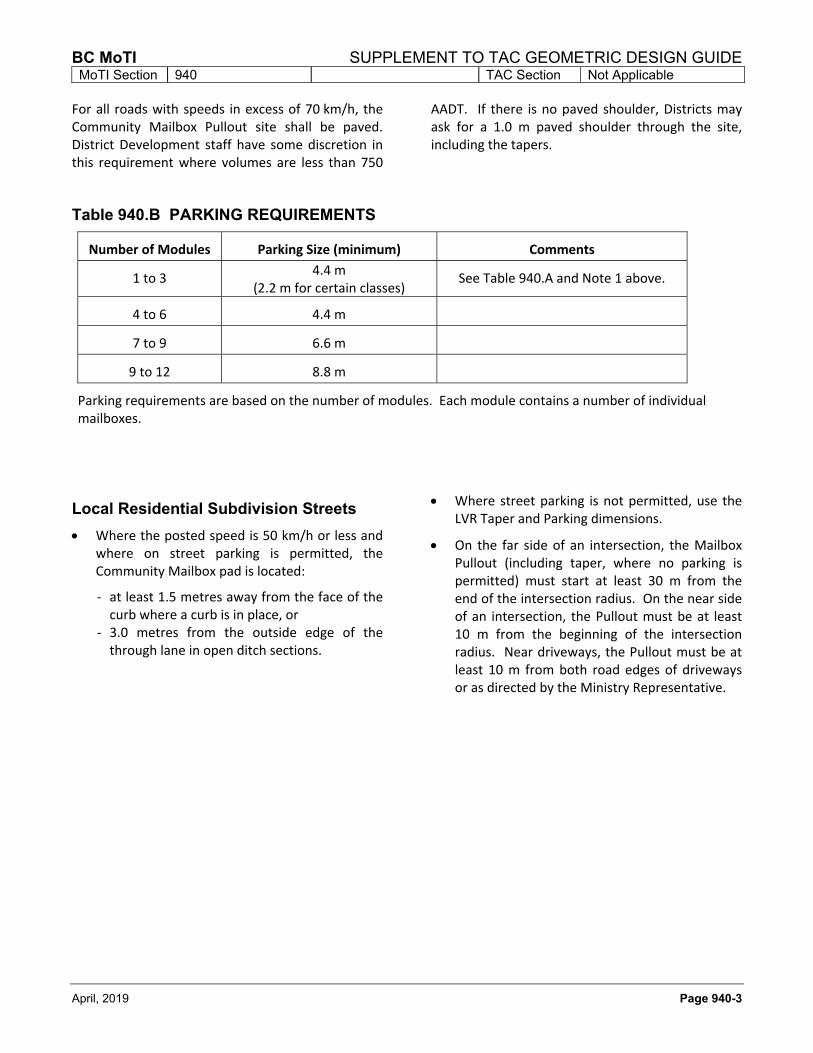
Table 940.B PARKING REQUIREMENTS
Number of Modules Parking Size (minimum) Comments
1 to 3 4.4 m
(2.2 m for certain classes) See Table 940.A and Note 1 above.
4 to 6 4.4 m
7 to 9 6.6 m
9 to 12 8.8 m
Parking requirements are based on the number of modules. Each module contains a number of individual mailboxes.
Local Residential Subdivision Streets
Where the posted speed is 50 km/h or less and where on street parking is permitted, the Community Mailbox pad is located:
‐ at least 1.5 metres away from the face of the curb where a curb is in place, or
‐ 3.0 metres from the outside edge of the through lane in open ditch sections.
Where street parking is not permitted, use the LVR Taper and Parking dimensions.
On the far side of an intersection, the Mailbox Pullout (including taper, where no parking is permitted) must start at least 30 m from the end of the intersection radius. On the near side of an intersection, the Pullout must be at least 10 m from the beginning of the intersection radius. Near driveways, the Pullout must be at least 10 m from both road edges of driveways or as directed by the Ministry Representative.
SUPPLEMENT TO TAC GEOMETRIC DESIGN GUIDE BC MoTI MoTI Section 940 TAC Section Not Applicable
Page 940-4 April, 2019
This page is intentionally left blank
BC MoTI SUPPLEMENT TO TAC GEOMETRIC DESIGN GUIDE MoTI Section 950 TAC Section Not Applicable
April, 2019 Page 950-1
950 COMMERCIAL VEHICLE INSPECTION SITES
950.01 COMMERCIAL VEHICLE
INSPECTION STATIONS Refer to Technical Circular T‐13/06 The design of commercial vehicle inspection stations shall be in accordance with the current Commercial Vehicle Inspection Station Design Guide. All of the roadway features required to access and egress the inspection station site such as ramps, acceleration and deceleration lanes or intersections with the highway shall also be in accordance with the TAC Geometric Design Guide for Canadian Roads and the BC Supplement to TAC Geometric Design Guide. The following traffic operation considerations and design criteria should be used when selecting where the commercial vehicle inspection station is to be located:
design for decision sight distance at the approaches to the intersection or the diverging gores of ramps that provide access to the inspection station;
design for decision sight distance for the highway section upstream of the location where the traffic exiting the inspection station and the through traffic on the highway complete their merging manoeuvre;
design exit ramps from the inspection station to allow commercial vehicles to accelerate as close as possible to the posted speed on the highway (desirable minimum shall be posted highway speed less 15 km/h) before the end of the merge point between the traffic exiting the station and the highway traffic;
in cases where the station is accessed through an intersection, locate the intersection and design the highway alignment at the
approaches to achieve both intersection turning sight distance and decision sight distance for the posted speed;
design merge, diverge and weave areas for level of service ‘C’ or better for the horizon year design volume; and
for a median station installation, perform a safety risk analysis of the highway segment to ensure that it is an appropriate location.
950.02 MOBILE WEIGH SCALE PULLOUTS
A mobile weigh scale pullout is used for periodic roadside inspections and does not require a building or permanent scale. The site is basically a shoulder widening similar to some highway pull offs for rest stops or brake checks. Figure 950.A provides guidelines for two layout options that are primarily dependent upon traffic volumes and number of lanes. It is the responsibility of the Senior Traffic Operations Engineer to decide which option is to be used. These guidelines are for all classes of highway except freeways and expressways. The use of mobile weigh scale pullouts is not conducive to maintaining the free flow nature of freeways and expressways. These higher class highways would typically have full sized commercial vehicle inspection stations (refer to 950.01).
SUPPLEMENT TO TAC GEOMETRIC DESIGN GUIDE BC MoTI MoTI Section 950 TAC Section Not Applicable
Page 950-2 April, 2019
Figure 950.A Mobile Weigh Scales
BC MoTI SUPPLEMENT TO TAC GEOMETRIC DESIGN GUIDE MoTI Section 960 TAC Section Not Applicable
April, 2019 Page 960-1
960
TRANSIT FACILITIES
960.01 INTRODUCTION
The purpose of this chapter is to provide information and guidance to designers in carrying out design assignments that involve transit facilities on roads under the jurisdiction of the British Columbia Ministry of Transportation and Infrastructure (BC MoTI). The guidelines are based on the general principles outlined in the following guides:
1) BC Transit Infrastructure Design Guidelines;
2) The Greater Vancouver Transportation Authority (TransLink) Bus Infrastructure Design Guidelines;
3) Transportation Association of Canada (TAC) Geometric Design Guide for Canadian Roads;
4) The American Association of State Highway and Transportation Officials (AASHTO): A Policy on Geometric Design of Highways and Streets.
It should be noted that in the Province of British Columbia, transit services are provided by TransLink within the Greater Vancouver Region and by BC Transit in the rest of the Province. Both agencies have developed detailed transit infrastructure design guidelines, as noted above. The TransLink guide is currently not available online; contact their Infrastructure Program Management team at [email protected] for the latest publication. As the material covered in this chapter is not intended to be used as comprehensive guidelines on the design of transit facilities, the designer should contact the appropriate transit agency prior to starting the design assignment. This is to ensure that the design of the transit facility is coordinated and consistent with the operational requirements of the transit agency. In many cases, the designer is required to make design submissions to the applicable transit agency and its representative(s) for approval prior to finalizing the design.
The BC MoTI and the transit service provider share the responsibility to ensure that the resulting design is safe and convenient for roadway and transit users.
960.02 TRANSIT FACILITY
DESIGN REQUIREMENTS
The design assignment may incorporate the whole transit facility or the connection component between the transit facility and the adjacent roadways. Whether or not the transit facility is a major or a minor part of the design scope, the designer should be fully aware of the requirements of the transit provider and have the following information available:
• Present and future traffic volumes, including all modes of transportation using the corridor such as cars, trucks, buses, bicycle and pedestrian traffic;
• Present and future traffic movements at intersections, including the desire lines of pedestrians and cyclists crossing the intersection legs, bus route and turning information, type of traffic control and signal timing plan for each intersection in the vicinity of the project; and
• The location of high traffic generators and destinations within and near the project limits.
Whether the transit facility component is small or large in a design assignment, the transit provider’s representative should be involved in reviewing the design drawings at various stages of the project.
SUPPLEMENT TO TAC GEOMETRIC DESIGN GUIDE BC MoTI MoTI Section 960 TAC Section Not Applicable
Page 960-2 April, 2019
960.02.01 Design Vehicle Dimensions
For rural and suburban highways, the typical design transit vehicle is the 14 metre long Intercity Bus, as shown in Figure 960.A. The dimension of the intercity bus could also be used for accommodating other transit vehicles on highways such as Greyhound and Pacific Coach Lines as well as tour buses. For urban streets, the transit design vehicles are the standard 12.7 metre long bus (BC Transit New Flyer Hybrid) and, when appropriate, the 18.3 metre long articulated bus (TransLink), as shown in Figure 960.B and Figure 960.C. It should be noted that, with the side mirrors included, the width of these three design vehicles is 3.1 metres. Designers are encouraged to consult with the local transit service provider to obtain information about the appropriate transit vehicle that will be used for the designated bus route and include it in the project’s Design Criteria sheet.
Figure 960.A Intercity Bus Dimensions
Figure 960.B Standard Bus Dimensions
Figure 960.C Articulated Bus Dimensions
Turning Capability
The minimum turning radii for the outer front tire should be: Intercity Bus 13.9 m Standard Bus 13.4 m Articulated Bus 13.0 m These radii are based on speeds of 15 km/h or less. The bicycle rack on the front of the bus, if equipped and fully extended, will increase the bus turning sweep by approximately 0.3 m towards the end of the turn.
960.02.02 Roadway Geometric Design In addition to roadway geometric design considerations outlined in BC Transit and TransLink Infrastructure Design Guidelines to accommodate bus operating characteristics, the following design considerations specific to highway operation should be taken into account: Horizontal Clearance to Traffic Barriers
For exclusive bus lanes, the recommended minimum lateral clearance to traffic barriers is 1.3 m, with an absolute minimum of 0.6 m. Exceptions to this minimum should only be applicable for temporary conditions such as during construction or rehabilitation work on the facility.
BC MoTI SUPPLEMENT TO TAC GEOMETRIC DESIGN GUIDE MoTI Section 960 TAC Section Not Applicable
April, 2019 Page 960-3
Vertical Clearance of Highway Structures
In general, the minimum vertical clearances of highway structures are stated in the BC MoTI Bridge Standards and Procedure Manual, i.e., 5 m for bridges and 5.5 m for pedestrian overpass.
The vertical clearances of all structures along the proposed route should be checked taking into account that transit vehicles vary in dimensions. According to the TransLink Bus Infrastructure Design Guidelines, a standard bus (typically 3.3 m high) requires a minimum vertical clearance of 4.5 m when it is being towed under a structure.
BC Transit also operates double-decker buses which are 4.3 m high. It is recommended to check not only the vertical clearance of the existing structures, but also tree branches and overhead signs along the proposed transit route. If considering potentially towing such a transit vehicle, a minimum vertical clearance of 5.5 m should be available unless an alternative route can be identified to facilitate such a special operation.
Additional Lane Width on Curves
Lanes should be widened within small radius curves (typically <100 m radius) to accommodate off-tracking characteristics of large vehicles as per the general recommendations in TAC section 3.2.5 Lane Widening on Curves. Pavement widening on curves will be of greater importance on roadways of lower design classification.
Sight Distances
Sight Distances include: Stopping Sight Distance, Decision Sight Distance, and Intersection Turning and Crossing Sight Distances. The general references for sight distance are the TAC Geometric Design Guide and AASHTO A Policy on Geometric Design of Highways and Streets.
Concrete Bus Pads
Buses, being heavy vehicles, are prone to cause deformation in asphalt pavement, especially at bus stop locations. In order to minimize pavement wear, a concrete bus pad should be considered for all high volume bus locations. Refer to the transit agency’s design guidelines for pavement structure thicknesses.
960.03 BUS STOP LOCATION AND
DESIGN
Bus stops provide the interface between passengers and buses. Therefore, they are one of the most critical components in transit infrastructure design. Bus stop design may include various aspects of transit operational requirements, but in general it involves the following three basic tasks:
1) Selection of the stop location based on spacing between bus stops, ridership and safety;
2) Placement of a bus stop, whether far-side, near-side or mid-block and consideration of the advantages and disadvantages associated with each choice; and
3) Physical configuration of the stop (including the type of bus stop, whether on-street stop or bus bay, and what layout and dimensions should be proposed) which will allow passengers to board, alight and make transfers in a safe and efficient manner.
As the transit service providers in the Province, both BC Transit and TransLink have developed criteria and dimensions for bus stop designs which should be used primarily in urban and suburban areas. For details, please refer to their Infrastructure Design Guidelines. It should be noted that for highways where the posted speed exceeds 90 km/h, bus stops and bays are not recommended; in such case the transit facility should be accessed by interchange ramps or located on a side road. On rural highways, bus bays often consist of a local widening of the shoulder where the bus stop is placed. Shoulder bus bays on rural highways allow for traffic to pass the stopping bus thus reducing delay to other traffic and maintaining roadway capacity. Shoulder bus bays also allow for passenger loading and unloading in a safer and more relaxed manner, and reduce the potential for buses to be rear-ended.
SUPPLEMENT TO TAC GEOMETRIC DESIGN GUIDE BC MoTI MoTI Section 960 TAC Section Not Applicable
Page 960-4 April, 2019
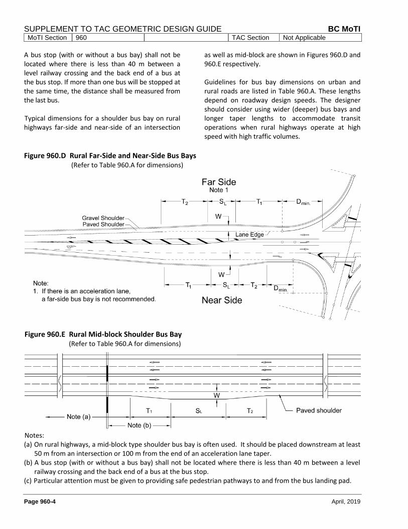
A bus stop (with or without a bus bay) shall not be located where there is less than 40 m between a level railway crossing and the back end of a bus at the bus stop. If more than one bus will be stopped at the same time, the distance shall be measured from the last bus. Typical dimensions for a shoulder bus bay on rural highways far-side and near-side of an intersection
as well as mid-block are shown in Figures 960.D and 960.E respectively. Guidelines for bus bay dimensions on urban and rural roads are listed in Table 960.A. These lengths depend on roadway design speeds. The designer should consider using wider (deeper) bus bays and longer taper lengths to accommodate transit operations when rural highways operate at high speed with high traffic volumes.
Figure 960.D Rural Far-Side and Near-Side Bus Bays
(Refer to Table 960.A for dimensions)
Figure 960.E Rural Mid-block Shoulder Bus Bay (Refer to Table 960.A for dimensions)
Notes: (a) On rural highways, a mid-block type shoulder bus bay is often used. It should be placed downstream at least
50 m from an intersection or 100 m from the end of an acceleration lane taper. (b) A bus stop (with or without a bus bay) shall not be located where there is less than 40 m between a level
railway crossing and the back end of a bus at the bus stop. (c) Particular attention must be given to providing safe pedestrian pathways to and from the bus landing pad.
BC MoTI SUPPLEMENT TO TAC GEOMETRIC DESIGN GUIDE MoTI Section 960 TAC Section Not Applicable
April, 2019 Page 960-5
Table 960.A Guidelines for Bus Bay Dimensions
Road Classification Urban Roads Rural Roads
Design Speed (km/h) ≤ 50 60 ≤70 80 90
W (m) 3.0 3.5
T1 (m) 18 25 50 (a) 50 (a) 50 (a)
T2 (m) 10 25 30 (a) 30 (a) 30 (a)
Dmin. (m) 6 15 50 50 50
SL (m) 16 20
Note (a) - These dimensions include some allowance for acceleration and deceleration
LEGEND W: The stop area width of a bus bay T1: The entry taper length T2: The exit taper length Dmin: The minimum distance to the bus bay taper from the end of curb return or painted gore point at the
nose of the intersection island (refer to Figures for appropriate dimensioning point). SL: The stop area length of a bus bay
960.04 TRANSIT PRIORITY
MEASURES
960.04.01 Queue Jumper Bus Lane A queue jumper lane refers to a special lane for transit buses to bypass the general traffic queue, usually at a near-side intersection location where queues frequently form. Queue jumpers have proven to be effective only if the transit vehicles can fully bypass queued traffic in the through lanes, particularly during peak periods. Figure 960.F shows a queue jumper design, which consists of a near-side bus bay and an exclusive bus lane, along with a bus priority signal. In designing a queue jumper, it is important to ensure that
1) the entry to the bus bay is not blocked by the traffic queue in the adjacent travel lane; and
2) the bay is set back far enough from the ‘weaving section’ to accommodate right turn vehicles.
In general, the length of a queue jumper should be the greater of the following:
• 95th percentile queue length in the adjacent through traffic lane based on the peak 15 minute design volume; or
• SL + Dmin + 15m
Dmin is the minimum distance from the bus stop ID pole to the painted gore point at the nose of the intersection island. Distances greater than Dmin may be required and can be determined by field observation or traffic simulation. In special circumstances where the required D distance cannot be achieved, approval will be required by BC MoTI and the transit agency.
SUPPLEMENT TO TAC GEOMETRIC DESIGN GUIDE BC MoTI MoTI Section 960 TAC Section Not Applicable
Page 960-6 April, 2019
Figure 960.F Queue Jumper Bus Bay (Refer to Table 960.A for dimensions)
960.04.02 Shoulder Bus Lane Bus lanes on highways cover long distances that allow transit vehicles to bypass congested travel lanes. They are provided either on the shoulder or in a median lane. A Shoulder Bus Lane allows certain buses to use the shoulder in designated areas to bypass congestion. Shoulder Bus Lanes are neither like general purpose traffic lanes, nor like exclusive bus lanes, for the following reasons:
• The widths of Shoulder Bus Lanes may be different than the adjacent through traffic lanes. Depending on the highway classification, the design speed and the operating conditions, the widths of Shoulder Bus Lanes typically vary between 3.3 m and 4 m. Additional shy distance width may be required adjacent to roadside barrier.
• Like normal shoulders, the Shoulder Bus Lane provides a refuge area for vehicles stranded due to breakdowns or collisions.
• Clear Zone distances are measured to the right side of the highway from the fog line (the lane marking between the outside traffic lane and the shoulder); therefore, the bus
has less effective clear zone distance than adjacent through traffic lanes.
Pavement in the Shoulder Bus Lane must be designed to accommodate bus traffic dynamic loads. A working example of the Highway 99 Transit Lane Project in Richmond, BC is shown in chapter 8 of the BC Transit Infrastructure Design Guidelines. This project is a 4.0 m wide and 3.0 km long dedicated Shoulder Bus Lane. In addition to the diagrams, tables and calculation formula provided in this working example, the following technical issues pertaining to the project are discussed in greater detail:
• Project overview
• Key design elements
• Stop bar location
• Design length for acceleration
• Vehicular clearance periods
• Intersection detectors
• Advanced warning sign
• Bus check-in and check-out detector; and
• Bus signal display, etc.
BC MoTI SUPPLEMENT TO TAC GEOMETRIC DESIGN GUIDE MoTI Section 960 TAC Section Not Applicable
April, 2019 Page 960-7
960.05 OFF-STREET TRANSIT
FACILITIES
960.05.01 Transit Exchanges The design of transit exchanges is a comprehensive process which requires consideration of physical and operational context, including transit network, land size, passenger access, transit operational requirements and adjacent land use. TransLink Bus Infrastructure Design Guidelines include the following specific topics pertaining to transit exchanges:
• Transit Exchange Design and Considerations
• Type of Transit Exchange Design
• Geometric Requirement of Bus Bays
• Loading Area Estimation
• Bus-Pedestrian-Cyclist Conflicts within a Transit Exchange
• Passenger Access, Boarding and Alighting Activities, etc.
Similarly, BC Transit Infrastructure Design Guidelines cover the following aspects of a transit exchange design:
• Location Consideration
• Design Consideration
• Bus-Pedestrian Conflicts within a Transit Exchange
• Passengers Access, Boarding and Alighting Activities
• Loading Area Estimation
960.05.02 Park-and-Ride Lots Park-and-Ride lots provide parking spaces for people transferring from a private vehicle to public transit or carpools/vanpools. Park-and-Ride lots are mostly located at or near a major highway intersection or interchange. The location and capacity of a park-and-ride lot is governed by the nature of the transit service and regional transportation objectives.
The site for a park-and-ride lot is usually decided as a result of planning and traffic studies which form the basis of an agreement among BC MoTI, the Transit provider and municipality. The agreement typically outlines each party’s responsibilities for supplying the land and funds, doing the design and construction and ultimately the future maintenance and upgrade of the park-and-ride lot. The content of the agreement will help determine the scope of the design assignment. The planning and traffic studies will assist in producing the Design Criteria Sheet and justification for possible exceptions to design guidelines. Design features should be in compliance with the requirements and guidelines of the parties involved in the agreement (e.g. road agency, transit agency, local authority). TransLink Bus Infrastructure Design Guidelines include the following specific topics pertaining to park-and-ride lots:
• General Considerations
• Layout and Design Parameters Similar to TransLink, BC Transit guidelines also cover the following topics:
• Location Considerations
• Design Considerations, including elements to be considered such as parking supply, parking stall type, dimension and configuration, site circulations, site security and paving requirement.
BC Transit also provides design examples of three park-and-ride lots in the Lower Mainland area. In addition, both agencies provide some general discussion in their guidelines on the design of passenger pick-up and drop-off facilities.
SUPPLEMENT TO TAC GEOMETRIC DESIGN GUIDE BC MoTI MoTI Section 960 TAC Section Not Applicable