Page 1
691
Chapter Fourteen
Fundamentals of Descriptive Geometry
ObjectivesAfter completing this chapter, you will be able to:
1. Defi ne the theoretical principles of
descriptive geometry.
2. Identify and defi ne the direct view,
revolution, and fold-line methods.
3. Identify, defi ne, and create principal
and nonprincipal lines and planes in
various spatial locations.
4. Defi ne and create a true-length view
and point view of a line by the auxil-
iary method.
5. Identify, defi ne, and create parallel,
intersecting, and perpendicular lines.
6. Construct true-length lines in a plane.
7. Construct an edge view and true-size
view of a plane by the auxiliary view
method.
8. Determine the angle between a line
and a plane and between two planes.
IntroductionThis chapter describes the concepts of de-
scriptive geometry as applied to solving spa-
tial problems. The basic geometric elements
Nothing great can be accomplished
without enthusiasm.
—Ralph Waldo Emerson
Chapter F
ourteen
ber28376_ch14.indd 691ber28376_ch14.indd 691 1/2/08 3:13:16 PM1/2/08 3:13:16 PM
Page 2
692 PART 3 Descriptive Geometry
of points, lines, and planes, used extensively in traditional
descriptive geometry applications, are defi ned by example
problems. These 2-D geometric elements can be combined
with 3-D geometric primitives to solve design problems,
utilizing 3-D CAD and solid modeling software. Fig-
ure 14.1 illustrates the application of descriptive geometry
concepts in the design of a chemical plant. For the plant to
function safely, pipes must be placed to intersect correctly
and to clear each other by a specifi ed distance, and they
must correctly intersect the walls of buildings. Descriptive
geometry is used to solve these types of spatial problems.
14.1 Descriptive Geometry MethodsDescriptive geometry is the graphic representation of the
plane, solid, and analytical geometry used to describe real
or imagined technical devices and objects. It is the sci-
ence of graphic representation in engineering design that
forms the foundation, or grammar, of technical drawings.
French mathematician Gaspard Monge (1746–1818)
organized and developed the “science” of descriptive ge-
ometry in the late 1700s. Monge used orthographic pro-
jection and revolution methods to solve design problems
associated with complex star-shaped military fortifi ca-
tions in France. Shortly thereafter, in both France and
Germany, descriptive geometry became a required part
of each country’s national education programs. In 1816,
Claude Crozet introduced descriptive geometry into the
curriculum of West Point in the United States, and in 1821
he published Treatise on Descriptive Geometry, the fi rst
important English writing on descriptive geometry.
Until CAD technology was developed and widely ad-
opted as a graphics tool, three traditional methods were
used to solve spatial design problems through the applica-
tion of descriptive geometry: the direct view method, the
revolution method, and the fold-line method. In certain
cases, one method may be preferred over another because
of its ease in determining the problem solution. However,
all three methods are acceptable.
The direct view method is consistent with the use of
3-D solid modeling to solve spatial problems. In cases
where another method gives an equally effective or more
direct solution to a problem, both methods are presented.
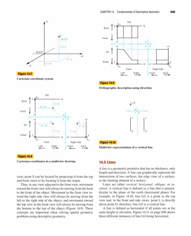
Figure 14.2 illustrates the direct view method to fi nd the
true size of the inclined plane (view 1). The direct view
method, sometimes referred to as the natural method, places the observer at an infi nite distance from the object,
with the observer’s line of sight perpendicular to the ge-
ometry (i.e., the object’s major features) in question.
Figure 14.3 illustrates the revolution method of fi nd-
ing the true size of the inclined plane. In this method, the
geometry, such as a point, line, plane, or entire object,
is revolved about an axis until that geometry is parallel
to a plane of projection that will show the true shape of
the revolved geometry. In the fi gure, an oblique face has
been revolved to bring it parallel to the profi le plane, in
which the true shape of that surface is shown. The revolu-
tion method is satisfactory when a single entity or simple
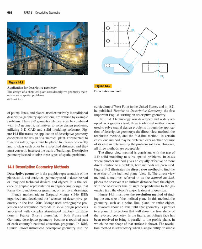
Figure 14.1
Application for descriptive geometryThe design of a chemical plant uses descriptive geometry meth-ods to solve spatial problems.
(© Photri, Inc.)
RP1
RP1
RP1
Figure 14.2
Direct view method
ber28376_ch14.indd 692ber28376_ch14.indd 692 1/2/08 3:13:20 PM1/2/08 3:13:20 PM
Page 3
CHAPTER 14 Fundamentals of Descriptive Geometry 693
geometry is revolved; however, when the geometry is
complex, this method tends to be confusing.
Figure 14.4 illustrates the fold-line method of fi nding
the true size of the inclined plane. The fold-line method
is also referred to as the glass box method, which was
discussed in Chapters 7, 10, and 13. Using the fold-line
method, the inclined face is projected onto an auxiliary
plane that is parallel to the face. The difference between
this method and the revolution method is that, in the rev-
olution method, the geometry is revolved to one of the
principal projection planes, while the fold-line method
uses an auxiliary plane parallel to the desired geometry.
The auxiliary projection plane is then “unfolded” so that
it is perpendicular to the line of sight.
CAD technology, specifi cally 3-D solid modeling, al-
lows the use of both the revolution and direct view meth-
ods. The revolution method is the underlying principle for
the “translation of geometry through rotation” capabilities
of CAD. It is assumed that the principal projection plane
to which the geometry revolves is the computer screen.
CAD and solid modeling software also utilize the prin-
ciples of the direct view method. The user can specify the
view desired, and the CAD system will position the line
of sight perpendicular to the geometry in question. The
geometry is consequently parallel to the projection plane
(i.e., the computer screen).
14.2 Reference PlanesBecause of the practical applications to 3-D CAD and
solid modeling, the direct view method is used here to de-
scribe the various applications of descriptive geometry.
Although there are differences between the direct view
method and the fold-line method, either will work for solv-
ing spatial design problems that require the use of descrip-
tive geometry.
In Figure 14.5 on the next page, a reference plane AA
is illustrated. In Figure 14.5A, the reference plane AA is
placed on the back of the object. This would place the edge
view of the reference plane at the rear of the top and pro-
fi le views in the multiview drawing. All measurements are
taken from this reference plane to specifi c points on the ob-
ject in the multiview. Points 1 through 6 can be measured
perpendicular from reference plane AA in either the top or
profi le view by measuring along the Z axis.
The reference plane can be placed anywhere with re-
spect to the object. In Figure 14.5B, it is placed in front
of the object, which places it between the horizontal and
front views in the multiview drawing. All measurements
are taken from this reference plane to specifi c points on
the object in the front and profi le views. In the position
shown, the reference plane placed between the horizontal
and front views is labeled H–F; a reference plane between
the frontal and profi le planes would be labeled F–P, fol-
lowing the conventions discussed in Chapter 13.
Normally, the edge view of a reference plane is repre-
sented by a phantom line consisting of two short dashes,
a long dash, and two short dashes, in that order. The use
of a reference plane between the views allows for the use
of either the direct view or fold-line method for solving
descriptive geometry problems.
F
F
H
Figure 14.3
Revolution method
F P
1
F
F
H
Figure 14.4
Fold-line method
ber28376_ch14.indd 693ber28376_ch14.indd 693 1/2/08 3:13:21 PM1/2/08 3:13:21 PM
Page 4
694 PART 3 Descriptive Geometry
Practice Exercise 14.1For this Practice Exercise, do Problem 14.1 located at the
end of this chapter.
14.3 PointsA point has no width, height, or depth. A point represents a
specifi c position in space, as well as the end view of a line
or the intersection of two lines. The position of a point is
marked by a small symmetrical cross and is located using
Cartesian coordinates (Figure 14.6).
14.4 The Coordinate SystemBefore a graphical solution of a problem can be attempted,
the relative locations of two or more points must be de-
scribed verbally or graphically from a known reference.
One of the most generally used reference systems is the
Cartesian coordinate system, which was described ex-
tensively earlier in this text. (See Section 8.3.) The Carte-
sian coordinate system is the basis for both traditional and
CAD systems. Any point can be located by describing its
location with respect to the three axes X,Y,Z (Figure 14.7).
With the Cartesian coordinate system, points are lo-
cated with respect to the origin (0,0,0) and to each other.
For example, in Figure 14.8 point S is four inches to the
right, three inches above, and two inches in front of the
origin (4,3,2). Using orthographic projection, in the top
view, point S is located four inches to the right and two
inches in front of the origin, but the height cannot be de-
termined. In the front view, point S is four inches to the
right and three inches above the origin. In the right side
Z
Z
Z
A
A
A
12
34
5
6
P5 , P6
P4 , P3
P2 , P1
A
A
AA
Z Z
Z
Z
F3
F56F
F1 F2
F4
4 ,H 5H2 ,H 3H1 ,H 6H
(A)
Z Z
Z
Z
F3
F56F
F1 F2
F4
4 ,H 5H2 ,H 3H1 ,H 6H
P2 , P1
P4 , P3
P5 , P6
H
F
PF
12
4
Z
Z
Z
5
36
Z
Z
(B)
H
Figure 14.5
Using reference planesThe subscripts used with each number in the multiviews indi-cate which view the plane is in: F indicates front, H indicates horizontal or top, and P indicates profi le or side view.
Y
X
Z
POINT MARKERS
(6,2,-3)(2,1,0)
Figure 14.6
Graphical representation of a point
ber28376_ch14.indd 694ber28376_ch14.indd 694 1/2/08 3:13:21 PM1/2/08 3:13:21 PM
Page 5
CHAPTER 14 Fundamentals of Descriptive Geometry 695
view, point S can be located by projecting it from the top
and front views or by locating it from the origin.
Thus, in any view adjacent to the front view, movement
toward the front view will always be moving from the back
to the front of the object. Movement in the front view to-
ward the right side view will always be moving from the
left to the right side of the object, and movement toward
the top view in the front view will always be moving from
the bottom to the top of the object (Figure 14.9). These
concepts are important when solving spatial geometry
problems using descriptive geometry.
X = 4
Z = 2
Y = 3
(0,0,0)
+Y
+X
+Z
S
(4,3,2)
Figure 14.7
Cartesian coordinate system
Y = 3
+X
+Z
X = 4Z = 2
+Y
S
Y = 3
X = 4 Z = 2
XZ
Y
+Y
+X +Z
H
F PS S
0 H
0 F 0 PFront Right Side
Top
Left Right Front Back
Up
Down
Back
Front
Figure 14.8
Cartesian coordinates in a multiview drawing
+X
+Z
+Y
XZ
Y
+Y
+X +Z
H
F P
0 H
0 F 0 PFront Right Side
Top
Left Right Front Back
Up
Down
Back
Front
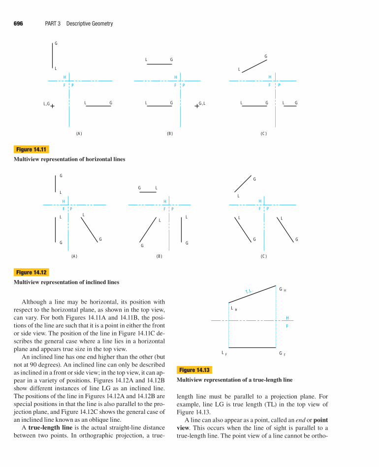
Figure 14.9
Orthographic description using direction
14.5 LinesA line is a geometric primitive that has no thickness, only
length and direction. A line can graphically represent the
intersection of two surfaces, the edge view of a surface,
or the limiting element of a surface.
Lines are either vertical, horizontal, oblique, or in-clined. A vertical line is defi ned as a line that is perpen-
dicular to the plane of the earth (horizontal plane). For
example, in Figure 14.10, line LG is a point in the top
view and, in the front and side views, point L is directly
above point G; therefore, line LG is a vertical line.
A line is defi ned as horizontal if all points are at the
same height or elevation. Figure 14.11 on page 696 shows
three different instances of line LG being horizontal.
H
F P
L,G
L
G
L
G
Figure 14.10
Multiview representation of a vertical line
ber28376_ch14.indd 695ber28376_ch14.indd 695 1/2/08 3:13:22 PM1/2/08 3:13:22 PM
Page 6
696 PART 3 Descriptive Geometry
Although a line may be horizontal, its position with
respect to the horizontal plane, as shown in the top view,
can vary. For both Figures 14.11A and 14.11B, the posi-
tions of the line are such that it is a point in either the front
or side view. The position of the line in Figure 14.11C de-
scribes the general case where a line lies in a horizontal
plane and appears true size in the top view.
An inclined line has one end higher than the other (but
not at 90 degrees). An inclined line can only be described
as inclined in a front or side view; in the top view, it can ap-
pear in a variety of positions. Figures 14.12A and 14.12B
show different instances of line LG as an inclined line.
The positions of the line in Figures 14.12A and 14.12B are
special positions in that the line is also parallel to the pro-
jection plane, and Figure 14.12C shows the general case of
an inclined line known as an oblique line.
A true-length line is the actual straight-line distance
between two points. In orthographic projection, a true-
(A)
H
F P
L,G
L
G
L G
(B)
H
F P
G,L
L G
L G
(C)
H
F P
L
L
G
L G G
Figure 14.11
Multiview representation of horizontal lines
F
H
G H
L H
L F G F
T.L.
Figure 14.13
Multiview representation of a true-length line
length line must be parallel to a projection plane. For
example, line LG is true length (TL) in the top view of
Figure 14.13.
A line can also appear as a point, called an end or point view. This occurs when the line of sight is parallel to a
true-length line. The point view of a line cannot be ortho-
(C)
H
F P
L
G
L
G
G
L
(B)
H
F P
L
G
L
G
G L
(A)
H
F P
L
G
L
G
G
L
Figure 14.12
Multiview representation of inclined lines
ber28376_ch14.indd 696ber28376_ch14.indd 696 1/2/08 3:13:22 PM1/2/08 3:13:22 PM
Page 7
CHAPTER 14 Fundamentals of Descriptive Geometry 697
F
H
H
1
12
POINT VIEW
L 1
G 1
G H
L H
L F
G F
,L 2G 2
T.L.
Figure 14.14
Point view of a line
graphically determined without fi rst drawing the line in a
true-length position (Figure 14.14).
A principal line is parallel to one of the three princi-
pal projection planes. A line that is not parallel to any of
the three principal planes is called an oblique line and
will appear foreshortened in any of these planes.
A frontal line is a principal line that is parallel to, and
therefore true length in, a frontal plane. A frontal line can
be viewed true length from either a front or back view
(Figure 14.15A). A horizontal line is a principal line that
is parallel to, and therefore true length in, a horizontal
plane. A horizontal line can be viewed true length from
either a top or bottom view (Figure 14.15B). A profi le line
is a principal line that is parallel to, and therefore true
length in, a profi le plane. A profi le line can be viewed true
length from either a left or right side view (Figure 14.15C).
14.5.1 Spatial Location of a Line
The spatial location of a line must be determined before
a graphical representation of the line can be drawn. Lines
can be located graphically by any one of three different
methods: Cartesian coordinates, polar coordinates, or
world coordinates. These coordinate systems are discussed
in detail in Section 8.3.
14.5.2 Point on a Line
If a point lies on a line, it must appear as a point on that
line in all views of the line. Figure 14.16 on the next page
illustrates that point X lies on the line LG, but points Y
and Z do not. This can be verifi ed by looking in the top
view, where point Z is in front of the line LG, and in the
front view, where point Y is above the line LG.
14.5.3 True Length of a Line
A line will appear true length in a view if the line is par-
allel to the plane of projection and the line of sight is per-
pendicular to the projection plane. Confi rmation of paral-
lelism must be obtained by viewing the projection plane
(A) Frontal Line (B) Horizontal Line (C) Profile Line
H
PF
L
G
L
G
G L
T.L. L G GL
L
T.L.
H
F
G
P
LL
G G
T.L.
H
F
L
P
G
Figure 14.15
Principal lines: frontal, horizontal, and profi le
ber28376_ch14.indd 697ber28376_ch14.indd 697 1/2/08 3:13:22 PM1/2/08 3:13:22 PM
Page 8
698 PART 3 Descriptive Geometry
in an adjacent view. (See Section 10.4.3.) If the line is in-
deed parallel to the projection plane, the line will also be
parallel to the reference plane’s edge view in the adjacent
view (Figure 14.17).
Several techniques can be used to fi nd the true length
of a line. If the line is parallel to one of the principal pro-
jection planes, it can simply be projected onto that plane
and then measured. If the line is not parallel to a principal
projection plane, then either the auxiliary view or revolu-
tion method can be used.
Principles of Descriptive Geometry Rule 1:
True-Length Line
If a line is positioned parallel to a projection plane and the
line of sight is perpendicular to that projection plane, the line
will appear as true length.
The following steps describe how to use the auxiliary
view method to determine the true length of a line that is
not parallel to a principal projection plane.
Historical HighlightGaspard Monge
Gaspard Monge, the man known as “the father of descriptive
geometry,” was an incredibly talented man. He was a math-
ematician, a scientist, and an educator working in physics,
chemistry, analytical geometry, and, of course, descriptive
geometry.
Monge was born the son of a poor merchant in eighteenth
century France. His father managed to help him get a suffi -
cient education and Monge’s talent took him the rest of the
way. More specifi cally, while he was a student at Mezeres,
his unique solution to a problem involving a fortress design
got him promoted from assistant to a full professor. A couple
years later he was made a professor of mathematics and
later took over the physics department.
Unfortunately, Monge was not permitted to make his
unique solution publicly known; it was deemed a military
secret. He continued to work on the principles he had
used, and expanded and revised them so that they could
be used to help solve any technical graphics problem.
Then, in 1794, Monge helped to found the fi rst modern
engineering school, Ecole Polytechnique, and was fi nally
able to teach the principles of descriptive geometry. It was
during the next year that he published his book Geom-
etrie Descriptive. His work would change technical draw-
ings from what were simple pictures into actual plans or
engineering drawings.
Source: © Bettman/Corbis
Monge received many awards and honors in his life-
time, but they were all taken away when Louis XVIII
came to power. Monge had been very loyal to Napoléon
Bonaparte, and when Napoléon lost power Monge’s ca-
reer was ruined. He died in disgrace in 1818. There is a
positive note, however. Even after his death, Monge still
had students and followers who continued his work, over-
seeing further editions of Geometrie Descriptive.
F
H
HL
HX HY HG
HZ
FY
FL
FX
FZFG
Figure 14.16
Point on a line
698
ber28376_ch14.indd 698ber28376_ch14.indd 698 1/2/08 3:13:23 PM1/2/08 3:13:23 PM
Page 9
CHAPTER 14 Fundamentals of Descriptive Geometry 699
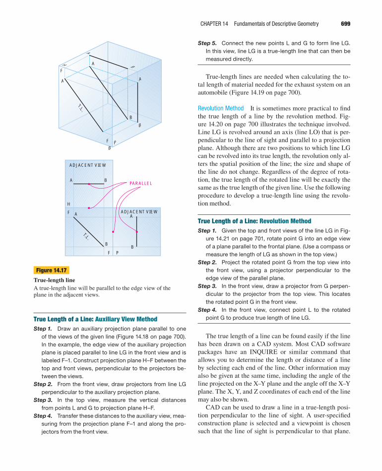
True Length of a Line: Auxiliary View MethodStep 1. Draw an auxiliary projection plane parallel to one
of the views of the given line (Figure 14.18 on page 700).
In the example, the edge view of the auxiliary projection
plane is placed parallel to line LG in the front view and is
labeled F–1. Construct projection plane H–F between the
top and front views, perpendicular to the projectors be-
tween the views.
Step 2. From the front view, draw projectors from line LG
perpendicular to the auxiliary projection plane.
Step 3. In the top view, measure the vertical distances
from points L and G to projection plane H–F.
Step 4. Transfer these distances to the auxiliary view, mea-
suring from the projection plane F–1 and along the pro-
jectors from the front view.
F
H
PF
A
B
A
B
B
A
A
B
T.L.
A
B
A
B
A B
ADJACENT VIEW
ADJACENT VIEW
PF
F
H
PARALLEL
T.L.
Figure 14.17
True-length lineA true-length line will be parallel to the edge view of the plane in the adjacent views.
Step 5. Connect the new points L and G to form line LG.
In this view, line LG is a true-length line that can then be
measured directly.
True-length lines are needed when calculating the to-
tal length of material needed for the exhaust system on an
automobile (Figure 14.19 on page 700).
Revolution Method It is sometimes more practical to fi nd
the true length of a line by the revolution method. Fig-
ure 14.20 on page 700 illustrates the technique involved.
Line LG is revolved around an axis (line LO) that is per-
pendicular to the line of sight and parallel to a projection
plane. Although there are two positions to which line LG
can be revolved into its true length, the revolution only al-
ters the spatial position of the line; the size and shape of
the line do not change. Regardless of the degree of rota-
tion, the true length of the rotated line will be exactly the
same as the true length of the given line. Use the following
procedure to develop a true-length line using the revolu-
tion method.
True Length of a Line: Revolution MethodStep 1. Given the top and front views of the line LG in Fig-
ure 14.21 on page 701, rotate point G into an edge view
of a plane parallel to the frontal plane. (Use a compass or
measure the length of LG as shown in the top view.)
Step 2. Project the rotated point G from the top view into
the front view, using a projector perpendicular to the
edge view of the parallel plane.
Step 3. In the front view, draw a projector from G perpen-
dicular to the projector from the top view. This locates
the rotated point G in the front view.
Step 4. In the front view, connect point L to the rotated
point G to produce true length of line LG.
The true length of a line can be found easily if the line
has been drawn on a CAD system. Most CAD software
packages have an INQUIRE or similar command that
allows you to determine the length or distance of a line
by selecting each end of the line. Other information may
also be given at the same time, including the angle of the
line projected on the X–Y plane and the angle off the X–Y
plane. The X, Y, and Z coordinates of each end of the line
may also be shown.
CAD can be used to draw a line in a true-length posi-
tion perpendicular to the line of sight. A user-specifi ed
construction plane is selected and a viewpoint is chosen
such that the line of sight is perpendicular to that plane.
ber28376_ch14.indd 699ber28376_ch14.indd 699 1/2/08 3:13:23 PM1/2/08 3:13:23 PM
Page 10
Figure 14.19Determining the lengths of material for the exhaust system in an automobile is an application for true-length lines.
L
O
Observer’s lineof sight after revolution
Line of sight whereaxis is seen as a pointview.
G
GR
GR
Projection planeafter revolution
Figure 14.20
Revolution of a line
Step 4Step 5
Step 1 Step 2 Step 3
F
H
F1
HG
HL
FG
FL
F
H
F1
HG
HL
FG
FL
F
H
F1
HG
HL
FG
FL
F
H
F1
HG
HL
FG
FL
G 1
L 1
F
H
F1
T.L.
HG
HL
FG
FL
G 1
L 1
Figure 14.18
True length of a line: auxiliary view method
700
ber28376_ch14.indd 700ber28376_ch14.indd 700 1/2/08 3:13:24 PM1/2/08 3:13:24 PM
Page 11
CHAPTER 14 Fundamentals of Descriptive Geometry 701
The line is then drawn on the plane. The essential concept
is that lines or planes can be drawn in true-length posi-
tions on user-specifi ed construction planes that can be lo-
cated in any spatial position.
14.5.4 Point View of a Line
A point view of a line occurs when the line of sight is
parallel to the line. The back end of the line is directly
behind the front end. As an example, if the eraser of a
pencil is viewed head on, the point of the pencil will not
be seen. Other objects appearing as a “point” include the
end of a straight piece of pipe, or the axis of a submarine
viewed from either the front or back (Figure 14.22 on the
next page).
Point View of a Line: Auxiliary View MethodStep 1. Given the top, front, and true-length auxiliary views
of a line in Figure 14.22, construct the edge view of refer-
ence plane 1–2 perpendicular to the true-length view of
Step 1 Step 2
Step 4
Step 3
Frontal View
H
F
Parallel tofrontalreferenceplane
Axis ofrevolution
G RH L H H,O
G H
L F
O FG F
H
F
Axis ofrevolution
G RH L H H,O
G H
L F
O FG F
H
F
Axis ofrevolution
G RH L H H,O
G H
L F
O FG FG RF
Parallel to frontalreference plane
H
F
TrueLength
Axis ofrevolution
G RH L H H,O
G H
L F
O FG FG RF
Figure 14.21
True length of a line by revolution
ber28376_ch14.indd 701ber28376_ch14.indd 701 1/2/08 3:13:24 PM1/2/08 3:13:24 PM
Page 12
702 PART 3 Descriptive Geometry
line LG. Construct a line parallel to the true-length view
of line LG and from point G.
Step 2. In the front view, measure the perpendicular dis-
tances from points L or G to reference plane F–1. Trans-
fer this distance to auxiliary view 1–2, measuring from
reference plane 1–2, to establish the point view (G,L) of
line LG.
In orthographic projection, the point view of a line is
found in a view adjacent to the true-length line view. In
Figure 14.23, in the front view, the point view of the line
is labeled L,G because L is closer to the viewer than G,
the opposite end of the line.
In CAD, a point view of a line can be obtained by plac-
ing the line parallel to one axis in a user-specifi ed construc-
FH
F1
T.L.
HG
HL
FG
FL
G1
L1
1 2
FH
F1
T.L.
HG
HL
FG
FL
G1
L1
1 2
G2,L2
Line of sight parallelto pencil creates a
point view
Figure 14.22
Point view of a line, auxiliary view method
tion plane and selecting a viewpoint that shows the axis as
a point. Because the line is parallel to that axis, the desired
line will also appear as a point, and the user-specifi ed con-
struction plane will appear as an edge (Figure 14.24).
Principles of Descriptive Geometry Rule 2:
Point View of a Line
If the line of sight is parallel to a true-length line, the line
will appear as a point view in the adjacent view. Corollary:
Any adjacent view of a point view of a line will show the
true length of the line.
H
F P
L,G
L
G
L G
T.L.
L
G
L,G
Viewer’s lineof sight.
LG viewed as truelength from thisline of sight.
F
T.L.
Figure 14.23
Line appearing as a point
L
G(0,0,0)
(1.25,0,0)+X
+Y+Z
Viewer’s currentline of sight
L,G
Edge view of plane;end view of line LG
+Y
+Z
Viewer’seventualline of sight
Current 2-D drawingplane
Figure 14.24
CAD application of a point view of a line
ber28376_ch14.indd 702ber28376_ch14.indd 702 1/2/08 3:13:24 PM1/2/08 3:13:24 PM
Page 13
CHAPTER 14 Fundamentals of Descriptive Geometry 703
A point and a lineIntersecting lines Two parallel lines Three non-linear points
H
F
BH
CH AH
DH
CF AF
BF DF
FA
H
F
FB FG
FL
AH L H
G HBH
HZHX
Y F
Z F
X F
TY
F
H HF
TG
TL
TA
FA FG
FL
Figure 14.25
Graphical representation of planes
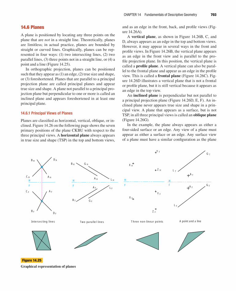
14.6 PlanesA plane is positioned by locating any three points on the
plane that are not in a straight line. Theoretically, planes
are limitless; in actual practice, planes are bounded by
straight or curved lines. Graphically, planes can be rep-
resented in four ways: (1) two intersecting lines, (2) two
parallel lines, (3) three points not in a straight line, or (4) a
point and a line (Figure 14.25).
In orthographic projection, planes can be positioned
such that they appear as (1) an edge, (2) true size and shape,
or (3) foreshortened. Planes that are parallel to a principal
projection plane are called principal planes and appear
true size and shape. A plane not parallel to a principal pro-
jection plane but perpendicular to one or more is called an
inclined plane and appears foreshortened in at least one
principal plane.
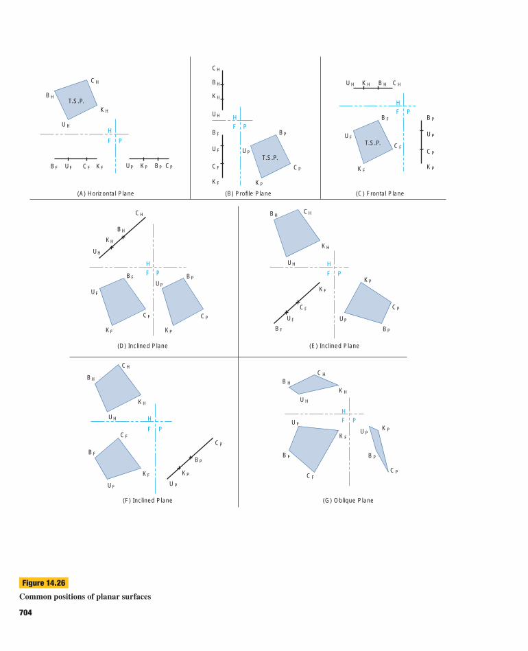
14.6.1 Principal Views of Planes
Planes are classifi ed as horizontal, vertical, oblique, or in-
clined. Figure 14.26 on the following page shows the seven
primary positions of the plane CKBU with respect to the
three principal views. A horizontal plane always appears
in true size and shape (TSP) in the top and bottom views,
and as an edge in the front, back, and profi le views (Fig-
ure 14.26A).
A vertical plane, as shown in Figure 14.26B, C, and
D, always appears as an edge in the top and bottom views.
However, it may appear in several ways in the front and
profi le views. In Figure 14.26B, the vertical plane appears
as an edge in the front view and is parallel to the pro-
fi le projection plane. In this position, the vertical plane is
called a profi le plane. A vertical plane can also be paral-
lel to the frontal plane and appear as an edge in the profi le
view. This is called a frontal plane (Figure 14.26C). Fig-
ure 14.26D illustrates a vertical plane that is not a frontal
or profi le plane, but it is still vertical because it appears as
an edge in the top view.
An inclined plane is perpendicular but not parallel to
a principal projection plane (Figure 14.26D, E, F). An in-
clined plane never appears true size and shape in a prin-
cipal view. A plane that appears as a surface, but is not
TSP, in all three principal views is called an oblique plane
(Figure 14.26G).
In the example, the plane always appears as either a
four-sided surface or an edge. Any view of a plane must
appear as either a surface or an edge. Any surface view
of a plane must have a similar confi guration as the plane
ber28376_ch14.indd 703ber28376_ch14.indd 703 1/2/08 3:13:25 PM1/2/08 3:13:25 PM
Page 14
(A) Horizontal Plane
T.S.P.
F P
H
BH
KH
CH
UH
FB FU CF KF UP KP BP PC
(B) Profile Plane
FH
T.S.P.
P
CH
BH
KH
UH
BF
UF
CF
KF KP
PU
PB
CP
(C) Frontal Plane
T.S.P.
HF P
HU KH BH HC
BF
FU
FC
FK PK
PC
PU
PB
(F) Inclined Plane
F
H
P
CH
HK
UH
FC
FB
UF
FK
U P
KP
BP
CP
(G) Oblique Plane
FH
P
B H
CH
HKUH
UF
FB
CF
FKUP
K P
PC
B P
(E) Inclined Plane
F
H
P
BH HC
HK
UH
FK
FC
FU
BF
KP
PC
BP
UP
(D) Inclined Plane
F
H
P
CH
BH
KH
HU
UF
BF
FC
FK
UP
PB
CP
KP
HB
Figure 14.26
Common positions of planar surfaces
704
ber28376_ch14.indd 704ber28376_ch14.indd 704 1/2/08 3:13:25 PM1/2/08 3:13:25 PM
Page 15
CHAPTER 14 Fundamentals of Descriptive Geometry 705
(i.e., the same number of sides and a similar shape) (Fig-
ure 14.27).
Principles of Descriptive Geometry Rule 3:
Planar Surface Views
Planar surfaces of any shape always appear either as edges or
as surfaces of similar confi guration.
14.6.2 Edge View of a Plane
The edge view of a plane occurs when the line of sight is
parallel to the plane.
Principles of Descriptive Geometry Rule 4:
Edge View of a Plane
If a line in a plane appears as a point, the plane appears as
an edge.
An oblique plane does not appear as an edge in any
principal view; therefore, a new view of the oblique plane
must be constructed showing the oblique plane as an edge.
This new (auxiliary) view is located by determining the
view in which a true-length line in the plane will appear
as a point.
Edge View of an Oblique Plane: Auxiliary View MethodStep 1. In the front view in Figure 14.28 on page 706, line
XA is drawn in the given plane XYZ and parallel to refer-
ence plane H–F. Point A is projected into the top view,
and true-length line AX is drawn.
Step 2. Auxiliary view 1 is drawn such that the line of sight
is parallel to true-length line AX, which will appear as a
point. Transferring measurements from the front view,
the given plane will appear as an edge in view 1 because
point AX is on a line in the plane. The point view of the
line is labeled A,X because point A is closest to the ob-
server in that view.
14.6.3 True Size of a Plane
A plane is viewed as true size and shape (normal) if the line
of sight is perpendicular to the plane. An estimation of the
number of square feet of shingles needed to cover a roof is
an application of the true-size plane (TSP). Other applica-
tions include calculating the square footage of sheet metal
(E)
(A) (B)
(D)(C)
Figure 14.27
Similar confi guration of planar surfaces
or the amount of cardboard needed to construct a shipping
container.
Principles of Descriptive Geometry Rule 5:
True-Size Plane
A true-size plane must be perpendicular to the line of sight
and must appear as an edge in all adjacent views.
ber28376_ch14.indd 705ber28376_ch14.indd 705 1/2/08 3:13:25 PM1/2/08 3:13:25 PM