68
1 Chapter one: DC circuit theory & Single-phase series AC circuits
1
Chapter one
DC circuit theory amp Single-phase series AC circuits
2
Current and Voltage
Current is the flow of electrons It is the time rate of change of
electrons passing through a defined area such as the cross-section of a
wire Because electrons are negatively charged the positive direction of
current flow is opposite to that of electron flow The mathematical
description of the relationship between the number of electrons (called
charge q ) and current i is
dqi
dt or q t i t d
The unit of charge is the coulomb (C) (in recognition of Charles
Augustin Coulomb French physicist and mathematician 1736-1806)
which represents 18624 10 electrons
The unit of current is the ampere or simply amp (in recognition of
Andre‟ Marie Ampere French physicist and mathematician 1775-1836)
which is defined as a coulomb per second
Ampere = coulomb second
Thus 1 amp is 18624 10 electrons moving from one body to another in 1
second
Energy is required to move a charge between two points in a circuit The
work per unit charge required to do this is called voltage The voltage
difference between two points in a circuit is a measure of the energy
required to move charge from one point to the other
3
The unit of voltage is volt (V) (in recognition of the Italian physicist
Alessandro Volta 1745-1827) which is defined as a charge of 1 joule of
energy per coulomb of charge
A joule (named in recognition of the English physicist James Joule
1818-1889) is a unit of energy or work and has the units of Newton X
meter Thus
volt = joule coulomb joule = Newton x meter
Current Source and Voltage Source
A voltage source is a device that causes a specified voltage to exist
between two points in a circuit The voltage may be time varying or time
invariant (for a sufficiently long time) Often the voltage is denoted by
E or V A battery is an example of this type of voltage
A current source causes a specified current to flow through a wire
containing this source
(a) Voltage source (b) constant voltage source (c) current source
AC DC and Electrical Signals
AC means Alternating Current and DC means Direct Current AC and
DC are also used when referring to voltages and electrical signals which
are not currents For example a 12V AC power supply has an
4
alternating voltage (which will make an alternating current flow) An
electrical signal is a voltage or current which conveys information
usually it means a voltage The term can be used for any voltage or
current in a circuit
Direct Current (DC)
Direct Current (DC) always flows in the same directionbut it may
increase and decrease A DC voltage is always positive (or always
negative)but it may increase and decrease Electronic circuits normally
require a steady DC supply which is constant at one value or a smooth
DC supply which has a small variation called ripple Cells batteries and
regulated power supplies provide steady DC which is ideal for electronic
circuits
Power supplies contain a transformer which converts the mains AC
supply to a safe low voltage AC Then the ACis converted to DC by a
bridge rectifier but the output is varying DC which is unsuitable for
electronic circuits Some power supplies include a capacitor to provide
smooth DC which is suitable for less-sensitive electronic circuits
including most of the projects on this website Lamps heaters and
motors will work with any DC supply
5
Alternating Current (AC)
Alternating Current (AC) flow one way then the other way continually
reversing direction An AC voltage is continually changing between
positive (+) and negative (-)
The rate of changing direction is called the frequency of the AC and it is
measured in hertz (Hz) which is the number of forwards-backwards
cycles per second
Mains electricity in the USA and Canada has a frequency 60 Hz while
other counties have a frequency of 50 Hz
An AC supply is suitable for powering some devices such as lamps and
heaters but almost all electronic circuits require a steady DC supply
13 Properties of electrical signals
6
Amplitude is the maximum voltage reached by the signal
It is measured in volts V
Peak voltage is another name for amplitude
Peak-peak voltage is twice the peak voltage (amplitude) When
reading an oscilloscope trace it is usual to measure peak-peak
voltage
Time period is the time taken for the signal to complete one cycle
It is measured in seconds (s) but time periods tend to be short so
milliseconds (ms)= 10 -3
s and microseconds (micros)10 -6
s
Frequency is the number of cycles per second
It is measured in hertz (Hz)
1 kilohertz (kHz) =1000 Hz and megahertz (MHz) =106 Hz
Frequency = 1 time periodamptime period = 1 frequency
Mains electricity in the Egypt has a frequency of 50Hz
so it has a time period of 150 = 002s = 20ms
14 Root Mean Square (RMS) Values
The value of an AC voltage is
continually changing from zero up to the
positive peak through zero to the
negative peak and back to zero again
Clearly for most of the time it is less than
the peak voltage so this is not a good
measure of its real effect
Instead we use the root mean square voltage (VRMS) which is 07 of the
peak voltage (Vpeak)
VRMS = 07 times Vpeak and Vpeak = 14 times VRMS
7
These equations also apply to current They are only true for sine
waves (the most common type of AC) because the 07 and 14 are
different values for other shapes
The RMS value is the effective value of a varying voltage or current
It is the equivalent steady DC (constant) value which gives the same
effect
What do AC meters show is it the RMS or peak voltage
AC voltmeters and ammeters show the RMS value of the voltage or
current DC meters also show the RMS value when connected to varying
DC providing the DC is varying quickly if the frequency is less than
about 10Hz you will see the meter reading fluctuating instead
Electrical Resistance
Electrical resistance is a measure of the degree to which an object
opposes an electric current through it Its reciprocal quantity is electrical
conductance (provided the electrical impedance is real) measured in
siemens Assuming a uniform current density an objects electrical
resistance is a function of both its physical geometry and the resistivity
of the material it is made from
A
lR
where
is the length
A is the cross sectional area and
ρ is the resistivity of the material
Electrical resistance shares some conceptual parallels with the
mechanical notion of friction The SI unit of electrical resistance is the
ohm symbol Ω
The electrical resistivity ρ (rho) of a material is given by
8
l
RA
Where ρ is the static resistivity (measured in ohm metres Ω-m)
R is the electrical resistance of a uniform specimen of the
material (measured in ohms Ω)
is the length of the piece of material (measured in metres m)
A is the cross-sectional area of the specimen (measured in
square metres msup2)
Electrical resistivity can also be defined as
J
E
Where E is the magnitude of the electric field (measured in volts per
metre Vm)
J is the magnitude of the current density (measured in amperes
per square metre Amsup2)
The conductivityσ (sigma) is defined as the inverse of the electrical
resistivity of the material or
1
Example
What is the value of the resistance of a copper wire with length 250m
and cross section area equals 25 mmsup2
Solution
Plug into the formula and using the value of the resistivity of the copper
from the table
A
lR
9
7211052
25010 x 1726
-8
x
xR
Ohms law
Ohms lawstates that in an electrical circuit the current passing through
a conductor between two points is directly proportional to the potential
difference (ie voltage drop or voltage) across the two points and
inversely proportional to the resistance between them and for the same
temperature
The mathematical equation that describes this relationship is
R
VI
Where I is the current in amperes (A) V is the potential difference
between two points of interest in volts (V) and R is the resistance it
measured in ohms (which is equivalent to volts per ampere)
The potential difference is also known as the voltage drop and is
sometimes denoted by U E or emf (electromotive force) instead of V
Example
Suppose the ammeter reads 52 A and the voltmeter indicates 233 kV
What is the resistance
Solution
Convert to amperes and volts getting I = 0000052 A and E = 2330 V
Then plug into the formula
R = 23300000052 = 45000000 = 45 M
Example
Find V when I = 120nA and R = 25 k
10
Solution
Convert to amperes and ohms getting 910120 x A and R = 31025 x
Then plug into the formula
mVxxxxRIV 3103102510120 339
Example
Find I when V = 22kV and R = 440
Solution
Using Ohms Law Eq
Ax
R
VI 50
440
1022 3
Electrical Power
The electric power P used in any part of a circuit is equal to the current I
in that part multiplied by the voltage V across that part of the circuit Its
formula is
P = VI
Where P = power W
V = voltage V
I = current A
If we know the current I and the resistance R but not the voltage V we
can find the power P by using Ohm‟s law for voltage so that
substituting V = IR
RIP 2
In the same manner if we know the voltage V and the resistance R but
not the current I we can find the power P by using Ohm‟s law for
current so that substitutingR
VI
11
R
VP
2
Example
The current through a 100Ω resistor to be used in a circuit is 020 A
Find the power rating of the resistor
Solution
WxRIP 410020 22
Example
If the voltage across a 25000 Ω resistor is 500 V what is the power
dissipated in the resistor
Solution
WR
VP 10
25000
500 22
19 Electrical energy
Electrical energy in any part of the circuit is that power of that part
multiplied of the time of consumption and it can be found from the
formula
Electrical energy U = Power x time
U =VIt (Joules)
Kilowatt hour (kWh)= 1000 watt hour
= 1000 x 3600 watt seconds or joule = 3 600 000 J
Example
A source emf of 5 V is supplies a current of 3 A for 10 minutes How
much energy is provided in this time
12
Solution
Energy = power x time power = voltage x current
U = VIt = 5 x 3 x (10 x 60) = 9000 Ws or J
= 9 kJ
Example
An electric heater consumes 18 MJ when connected to a 250 V supply
for 30 minutes Find the power rating of the heater and the current taken
from the supply
Solution
Power rating of heater = kWWx
x
t
UP 11000
6030
1081 6
Thus AV
PI 4
250
1000
Example
An electric bulb has a power 100 W If it works 10 hours per day find
the energy consumed in 1 month
Solution
Since energy = power x time
Then Energy U = P x t = 100 x 10 x 30
= 30000 Wh= 30 kWh
Series and Parallel Networks
Series circuits
TheFigure shows three resistors R1 R2 and R3 connected end to end
ie in series with a battery source of V volts Since the circuitis closed
13
a current I will flow and the pd across eachresistor may be determined
from the voltmeter readings V1 V2 and V3
In a series circuit
(a) the current I is the same in all parts of the circuit and hence the same
reading is found on each of the two ammeters shown and
(b) the sum of the voltages V1 V2 and V3 is equal to the total applied
voltage V ie
From Ohm‟s law
where R is the total circuit resistance
Since V = V1 + V2 + V3
then IR = IR1 + IR2 + IR3
Dividing throughout by I gives
Thus for a series circuit the total resistance is obtained by adding
together the values of the separate resistances
Example 113 For the circuit shown in the illustrated figure determine
(a) the battery voltage V
(b) the total resistance of the circuit and
(c) the values of resistance of resistors R1 R2 and R3 given
that the pd‟s across R1 R2 and R3 are 5 V 2 V and 6 V respectively
14
Solution
Voltage divider
The voltage distribution for the circuit shown in the Figure is given by
15
Example
Two resistors are connected in seriesacross a 24 V supply and a current
of 3 A flows in thecircuit If one of the resistors has a resistance of 2 Ω
determine (a) the value of the other resistor and
(b) the difference across the 2 Ω resistor
Solution
(a) Total circuit resistance
Value of unknown resistance
(b) Volt Difference across 2 Ω resistor V1 = IR1 = 3 x 2 = 6 V
Alternatively from above
Parallel networks
The Figure shows three resistorsR1 R2 and R3 connected across each
other iein parallel across a battery source of V volts
16
In a parallel circuit
(a) the sum of the currents I1 I2 and I3 is equal to the total
circuitcurrent I ie I = I1 + I2 + I3 and
(b) the source pdis the same across each of the resistors
From Ohm‟s law
where R is the total circuit resistance
Since I = I1 + I2 + I3
Dividing throughout by V gives
This equation must be used when finding the total resistance R of a
parallel circuit
For the special case of two resistors in parallel
17
Example
For the circuit shown in the Figure find
(a) the value of the supply voltage V
(b) the value of current I
Solution
(a) Vd across 20 Ω resistor = I2R2 = 3 x 20 = 60 V hencesupply
voltage V = 60 V since the circuit is connected in parallel
Current I = I1 + I2 + I3 = 6 + 3 + 1 = 10 A
Another solution for part (b)
18
Current division
For the circuit shown in the Figure the total circuit resistance RT
isgiven by
Example
For the circuit shown in the Figure find the current Ix
Solution
19
Commencing at the right-hand side of the arrangement shown in the
Figure below the circuit is gradually reduced in stages as shown in
Figure (a)ndash(d)
From Figure (d)
From Figure (b)
From the above Figure
Kirchhoffrsquos laws
Kirchhoffrsquos laws state
20
(a) Current Law At any junction in an electric circuit the total
current flowing towards that junction is equal to the total current
flowing away from the junction ie sumI = 0
Thus referring to Figure 21
I1 + I2 = I3 + I4 + I5 I1 + I2 - I3 - I4 - I5 = 0
(b) Voltage Law In any closed loop in a network the algebraic sum
of the voltage drops (ie products ofcurrent and resistance) taken
around the loop is equal to the resultant emf acting in that loop
Thus referring to Figure 22
E1 - E2 = IR1 + IR2 + IR3
(Note that if current flows away from the positive terminal of a source
that source is considered by convention to be positive Thus moving
anticlockwise around the loop of Figure 22 E1 is positive and E2 is
negative)
21
Example
Find the unknown currents marked in the following Figure
Solution
Applying Kirchhoff‟s current law
For junction B 50 = 20 + I1 hence I1 = 30 A
For junction C 20 + 15 = I2 hence I2 = 35 A
For junction D I1 = I3 + 120 hence I3 = minus90 A
(the current I3 in the opposite direction to that shown in the Figure)
For junction EI4 + I3 = 15 hence I4 = 105 A
For junction F 120 = I5 + 40 hence I5 = 80 A
Example
Determine the value of emf E in the following Figure
22
Solution
Applying Kirchhoff‟s voltage law
Starting at point A and moving clockwise around the loop
3 + 6 + E - 4 = (I)(2) + (I)(25) + (I)(15) + (I)(1)
5 + E = I (7)
Since I = 2 A hence E = 9 V
Example
Use Kirchhoff‟s laws to determine the currents flowing in each branch
of the network shown in Figure 24
23
Solution
1 Divide the circuit into two loops The directions current flows from
the positive terminals of the batteries The current through R is I1 + I2
2 Apply Kirchhoff‟s voltage law foreach loop
By moving in a clockwise direction for loop 1 of Figure 25
(1)
By moving in an anticlockwise direction for loop 2 of Figure 25
(2)
3 Solve equations (1) and (2) for I1 and I2
(3)
(4)
(ie I2 is flowing in the opposite direction to that shown in Figure 25)
From (1)
Current flowing through resistance R is
Note that a third loop is possible as shown in Figure 26giving a third
equation which can be used as a check
24
Example
Determine using Kirchhoff‟s laws each branch current for the network
shown in Figure 27
Solution
1 The network is divided into two loops as shown in Figure 28 Also
the directions current are shown in this Figure
2 Applying Kirchhoff‟s voltage law gives
For loop 1
(1)
25
For loop 2
(2)
(Note that the opposite direction of current in loop 2)
3 Solving equations (1) and (2) to find I1 and I2
(3)
(2) + (3) give
From (1)
Current flowing in R3 = I1-I2 = 652 ndash 637 = 015 A
Example
For the bridge network shown in Figure 29 determine the currents in
each of the resistors
26
Solution
- Let the current in the 2Ω resistor be I1 and then by Kirchhoff‟s current
law the current in the 14 Ω resistor is (I - I1)
- Let thecurrent in the 32 Ω resistor be I2 Then the current in the 11
resistor is (I1 - I2) and that in the3 Ω resistor is (I - I1 + I2)
- Applying Kirchhoff‟s voltage law to loop 1 and moving in a clockwise
direction
(1)
- Applying Kirchhoff‟s voltage law to loop 2 and moving in an
anticlockwise direction
(2)
Solve Equations (1) and (2) to calculate I1 and I2
(3)
(4)
(4) ndash (3) gives
Substituting for I2 in (1) gives
27
Hence
the current flowing in the 2 Ω resistor = I1 = 5 A
the current flowing in the 14 Ω resistor = I - I1 = 8 - 5 = 3 A
the current flowing in the 32 Ω resistor = I2 = 1 A
the current flowing in the 11 Ω resistor = I1 - I2 = 5 - 1 = 4 Aand
the current flowing in the 3 Ω resistor = I - I1 + I2 = 8 - 5 + 1 = 4 A
The Superposition Theorem
The superposition theorem statesIn any network made up of linear
resistances and containing more than one source of emf the resultant
current flowing in any branch is the algebraic sum of the currents that
would flow in that branch if each source was considered separately all
other sources being replaced at that time by their respective internal
resistances‟
Example
Figure 211 shows a circuit containing two sources of emf each with
their internal resistance Determine the current in each branch of the
network by using the superposition theorem
28
Solution Procedure
1 Redraw the original circuit with source E2 removed being replaced
by r2 only as shown in Figure (a)
2 Label the currents in each branch and their directions as shown
inFigure (a) and determine their values (Note that the choice of current
directions depends on the battery polarity which flowing from the
positive battery terminal as shown)
R in parallel with r2 gives an equivalent resistance of
From the equivalent circuit of Figure (b)
From Figure (a)
29
3 Redraw the original circuit with source E1 removed being replaced
by r1 only as shown in Figure (aa)
4 Label the currents in each branch and their directions as shown
inFigure (aa) and determine their values
r1 in parallel with R gives an equivalent resistance of
From the equivalent circuit of Figure (bb)
From Figure (aa)
By current divide
5 Superimpose Figure (a) on to Figure (aa) as shown in Figure 213
30
6 Determine the algebraic sum of the currents flowing in each branch
Resultant current flowing through source 1
Resultant current flowing through source 2
Resultant current flowing through resistor R
The resultant currents with their directions are shown in Figure 214
Theveninrsquos Theorem
Thevenin‟s theorem statesThe current in any branch of a network is that
which would result if an emf equal to the pd across a break made in
the branch were introduced into the branch all other emf‟s being
removed and represented by the internal resistances of the sources‟
31
The procedure adopted when using Thevenin‟s theorem is summarized
below
To determine the current in any branch of an active network (ie one
containing a source of emf)
(i) remove the resistance R from that branch
(ii) determine the open-circuit voltage E across the break
(iii) remove each source of emf and replace them by their internal
resistances and then determine the resistance r bdquolooking-in‟ at the break
(iv) determine the value of the current from the equivalent circuit
shownin Figure 216 ie
Example
Use Thevenin‟s theorem to find the current flowing in the 10 Ω resistor
for the circuit shown in Figure 217
32
Solution
Following the above procedure
(i) The 10Ω resistance is removed from the circuit as shown in Figure
218
(ii) There is no current flowing in the 5 Ωresistor and current I1 is given
by
Pd across R2 = I1R2 = 1 x 8 = 8 V
Hence pd across AB ie the open-circuit voltage across the break
E = 8 V
(iii) Removing the source of emf gives the circuit of Figure 219
Resistance
(iv) The equivalent Thacuteevenin‟s circuit is shown in Figure 220
Current
33
Hence the current flowing in the 10 resistor of Figure 217 is 0482 A
Example
A Wheatstone Bridge network is shown in Figure 221(a) Calculate the
current flowing in the 32Ω resistorand its direction using Thacuteevenin‟s
theorem Assume the source ofemf to have negligible resistance
Solution
Following the procedure
(i) The 32Ω resistor is removed from the circuit as shown in Figure
221(b)
(ii) The pd between A and C
34
The pd between B and C
Hence
Voltage between A and B is VAB= VAC ndash VBC = 3616 V
Voltage at point C is +54 V
Voltage between C and A is 831 V
Voltage at point A is 54 - 831 = 4569 V
Voltage between C and B is 4447 V
Voltage at point B is 54 - 4447 = 953 V
Since the voltage at A is greater than at B current must flow in the
direction A to B
(iii) Replacing the source of emf with short-circuit (ie zero internal
resistance) gives the circuit shown in Figure 221(c)
The circuit is redrawn and simplified as shown in Figure 221(d) and (e)
fromwhich the resistance between terminals A and B
(iv) The equivalent Thacuteevenin‟s circuit is shown in Figure 1332(f) from
whichCurrent
35
Hence the current in the 32 Ω resistor of Figure 221(a) is 1 A
flowing from A to B
Example
Use Thacuteevenin‟s theorem to determine the currentflowing in the 3 Ω
resistance of the network shown inFigure 222 The voltage source has
negligible internalresistance
Solution
Following the procedure
(i) The 3 Ω resistance is removed from the circuit as shown inFigure
223
(ii) The Ω resistance now carries no current
36
Hence pd across AB E = 16 V
(iii) Removing the source of emf and replacing it by its internal
resistance means that the 20 Ω resistance is short-circuited as shown in
Figure 224 since its internal resistance is zero The 20 Ω resistance may
thus be removed as shown in Figure 225
From Figure 225 Thacuteevenin‟s resistance
(iv)The equivalent Thevenin‟s circuit is shown in Figure 226
Nortonrsquos Theorem
Norton‟s theorem statesThe current that flows in any branch of a
network is the same as that which would flow in the branch if it were
connected across a source of electrical energy the short-circuit current
of which is equal to the current that would flow in a short-circuit across
the branch and the internal resistance of which is equal to the resistance
which appears across the open-circuited branch terminals‟
The procedure adopted when using Norton‟s theorem is summarized
below
To determine the current flowing in a resistance R of a branch AB of an
active network
(i) short-circuit branch AB
37
(ii) determine the short-circuit current ISC flowing in the branch
(iii) remove all sources of emf and replace them by their internal
resistance (or if a current source exists replace with an open circuit)
then determine the resistance rbdquolooking-in‟ at a break made between A
and B
(iv) determine the current I flowing in resistance R from the Norton
equivalent network shown in Figure 1226 ie
Example
Use Norton‟s theorem to determine the current flowing in the 10
Ωresistance for the circuit shown in Figure 227
38
Solution
Following the procedure
(i) The branch containing the 10 Ωresistance is short-circuited as shown
in Figure 228
(ii) Figure 229 is equivalent to Figure 228 Hence
(iii) If the 10 V source of emf is removed from Figure 229 the
resistance bdquolooking-in‟ at a break made between A and B is given by
(iv) From the Norton equivalent network shown in Figure 230 the
current in the 10 Ω resistance by current division is given by
39
As obtained previously in above example using Thacuteevenin‟s theorem
Example
Use Norton‟s theorem to determine the current flowing in the 3
resistance of the network shown in Figure 231(a) The voltage source
has negligible internal resistance
Solution
Following the procedure
(i) The branch containing the 3 resistance is short-circuited as shown in
Figure 231(b)
(ii) From the equivalent circuit shown in Figure 231(c)
40
(iii) If the 24 V source of emf is removed the resistance bdquolooking-in‟ at
a break made between A and B is obtained from Figure 231(d) and its
equivalent circuit shown in Figure 231(e) and is given by
(iv) From the Norton equivalent network shown in Figure 231(f) the
current in the 3 Ωresistance is given by
As obtained previously in previous example using Thevenin‟s theorem
Extra Example
Use Kirchhoffs Laws to find the current in each resistor for the circuit in
Figure 232
Solution
1 Currents and their directions are shown in Figure 233 following
Kirchhoff‟s current law
41
Applying Kirchhoff‟s current law
For node A gives 314 III
For node B gives 325 III
2 The network is divided into three loops as shown in Figure 233
Applying Kirchhoff‟s voltage law for loop 1 gives
41 405015 II
)(405015 311 III
31 8183 II
Applying Kirchhoff‟s voltage law for loop 2 gives
52 302010 II
)(302010 322 III
32 351 II
Applying Kirchhoff‟s voltage law for loop 3 gives
453 4030250 III
)(40)(30250 31323 IIIII
321 19680 III
42
Arrange the three equations in matrix form
0
1
3
1968
350
8018
3
2
1
I
I
I
10661083278568
0183
198
8185
1968
350
8018
xx
183481773196
801
196
353
1960
351
803
1
xx
206178191831
838
190
3118
1908
310
8318
2
xx
12618140368
0181
68
503
068
150
3018
3
xxx
17201066
18311
I A
19301066
20622
I A
01101066
1233
I A
43
1610011017204 I A
1820011019305 I A
Star Delta Transformation
Star Delta Transformations allow us to convert impedances connected
together from one type of connection to another We can now solve
simple series parallel or bridge type resistive networks using
Kirchhoff‟s Circuit Laws mesh current analysis or nodal voltage
analysis techniques but in a balanced 3-phase circuit we can use
different mathematical techniques to simplify the analysis of the circuit
and thereby reduce the amount of math‟s involved which in itself is a
good thing
Standard 3-phase circuits or networks take on two major forms with
names that represent the way in which the resistances are connected a
Star connected network which has the symbol of the letter Υ and a
Delta connected network which has the symbol of a triangle Δ (delta)
If a 3-phase 3-wire supply or even a 3-phase load is connected in one
type of configuration it can be easily transformed or changed it into an
equivalent configuration of the other type by using either the Star Delta
Transformation or Delta Star Transformation process
A resistive network consisting of three impedances can be connected
together to form a T or ldquoTeerdquo configuration but the network can also be
redrawn to form a Star or Υ type network as shown below
T-connected and Equivalent Star Network
44
As we have already seen we can redraw the T resistor network to
produce an equivalent Star or Υ type network But we can also convert
a Pi or π type resistor network into an equivalent Delta or Δ type
network as shown below
Pi-connected and Equivalent Delta Network
Having now defined exactly what is a Star and Delta connected network
it is possible to transform the Υ into an equivalent Δ circuit and also to
convert a Δ into an equivalent Υ circuit using a the transformation
process This process allows us to produce a mathematical relationship
between the various resistors giving us a Star Delta Transformation as
well as a Delta Star Transformation
45
These Circuit Transformations allow us to change the three connected
resistances (or impedances) by their equivalents measured between the
terminals 1-2 1-3 or 2-3 for either a star or delta connected circuit
However the resulting networks are only equivalent for voltages and
currents external to the star or delta networks as internally the voltages
and currents are different but each network will consume the same
amount of power and have the same power factor to each other
Delta Star Transformation
To convert a delta network to an equivalent star network we need to
derive a transformation formula for equating the various resistors to each
other between the various terminals Consider the circuit below
Delta to Star Network
Compare the resistances between terminals 1 and 2
Resistance between the terminals 2 and 3
46
Resistance between the terminals 1 and 3
This now gives us three equations and taking equation 3 from equation 2
gives
Then re-writing Equation 1 will give us
Adding together equation 1 and the result above of equation 3 minus
equation 2 gives
47
From which gives us the final equation for resistor P as
Then to summarize a little about the above maths we can now say that
resistor P in a Star network can be found as Equation 1 plus (Equation 3
minus Equation 2) or Eq1 + (Eq3 ndash Eq2)
Similarly to find resistor Q in a star network is equation 2 plus the
result of equation 1 minus equation 3 or Eq2 + (Eq1 ndash Eq3) and this
gives us the transformation of Q as
and again to find resistor R in a Star network is equation 3 plus the
result of equation 2 minus equation 1 or Eq3 + (Eq2 ndash Eq1) and this
gives us the transformation of R as
When converting a delta network into a star network the denominators
of all of the transformation formulas are the same A + B + C and which
is the sum of ALL the delta resistances Then to convert any delta
connected network to an equivalent star network we can summarized the
above transformation equations as
48
Delta to Star Transformations Equations
If the three resistors in the delta network are all equal in value then the
resultant resistors in the equivalent star network will be equal to one
third the value of the delta resistors giving each branch in the star
network as RSTAR = 13RDELTA
Delta ndash Star Example No1
Convert the following Delta Resistive Network into an equivalent Star
Network
Star Delta Transformation
Star Delta transformation is simply the reverse of above We have seen
that when converting from a delta network to an equivalent star network
that the resistor connected to one terminal is the product of the two delta
resistances connected to the same terminal for example resistor P is the
product of resistors A and B connected to terminal 1
49
By rewriting the previous formulas a little we can also find the
transformation formulas for converting a resistive star network to an
equivalent delta network giving us a way of producing a star delta
transformation as shown below
Star to Delta Transformation
The value of the resistor on any one side of the delta Δ network is the
sum of all the two-product combinations of resistors in the star network
divide by the star resistor located ldquodirectly oppositerdquo the delta resistor
being found For example resistor A is given as
with respect to terminal 3 and resistor B is given as
with respect to terminal 2 with resistor C given as
with respect to terminal 1
By dividing out each equation by the value of the denominator we end
up with three separate transformation formulas that can be used to
convert any Delta resistive network into an equivalent star network as
given below
50
Star Delta Transformation Equations
Star Delta Transformation allows us to convert one type of circuit
connection into another type in order for us to easily analyse the circuit
and star delta transformation techniques can be used for either
resistances or impedances
One final point about converting a star resistive network to an equivalent
delta network If all the resistors in the star network are all equal in value
then the resultant resistors in the equivalent delta network will be three
times the value of the star resistors and equal giving RDELTA = 3RSTAR
Maximum Power Transfer
In many practical situations a circuit is designed to provide power to a
load While for electric utilities minimizing power losses in the process
of transmission and distribution is critical for efficiency and economic
reasons there are other applications in areas such as communications
where it is desirable to maximize the power delivered to a load We now
address the problem of delivering the maximum power to a load when
given a system with known internal lossesIt should be noted that this
will result in significant internal losses greater than or equal to the power
delivered to the load
The Thevenin equivalent is useful in finding the maximum power a
linear circuit can deliver to a load We assume that we can adjust the
load resistance RL If the entire circuit is replaced by its Thevenin
equivalent except for the load as shown the power delivered to the load
is
51
For a given circuit V Th and R Th are fixed Make a sketch of the power
as a function of load resistance
To find the point of maximum power transfer we differentiate p in the
equation above with respect to RL and set the result equal to zero Do
this to Write RL as a function of Vth and Rth
For maximum power transfer
ThL
L
RRdR
dPP 0max
Maximum power is transferred to the load when the load resistance
equals the Thevenin resistance as seen from the load (RL = RTh)
The maximum power transferred is obtained by substituting RL = RTh
into the equation for power so that
52
RVpRR
Th
Th
ThL 4
2
max
AC Resistor Circuit
If a resistor connected a source of alternating emf the current through
the resistor will be a function of time According to Ohm‟s Law the
voltage v across a resistor is proportional to the instantaneous current i
flowing through it
Current I = V R = (Vo R) sin(2πft) = Io sin(2πft)
The current passing through the resistance independent on the frequency
The current and the voltage are in the same phase
53
Capacitor
A capacitor is a device that stores charge It usually consists of two
conducting electrodes separated by non-conducting material Current
does not actually flow through a capacitor in circuit Instead charge
builds up on the plates when a potential is applied across the electrodes
The maximum amount of charge a capacitor can hold at a given
potential depends on its capacitance It can be used in electronics
communications computers and power systems as the tuning circuits of
radio receivers and as dynamic memory elements in computer systems
Capacitance is the ability to store an electric charge It is equal to the
amount of charge that can be stored in a capacitor divided by the voltage
applied across the plates The unit of capacitance is the farad (F)
V
QCVQ
where C = capacitance F
Q = amount of charge Coulomb
V = voltage V
54
The farad is that capacitance that will store one coulomb of charge in the
dielectric when the voltage applied across the capacitor terminals is one
volt (Farad = Coulomb volt)
Types of Capacitors
Commercial capacitors are named according to their dielectric Most
common are air mica paper and ceramic capacitors plus the
electrolytic type Most types of capacitors can be connected to an
electric circuit without regard to polarity But electrolytic capacitors and
certain ceramic capacitors are marked to show which side must be
connected to the more positive side of a circuit
Three factors determine the value of capacitance
1- the surface area of the plates ndash the larger area the greater the
capacitance
2- the spacing between the plates ndash the smaller the spacing the greater
the capacitance
3- the permittivity of the material ndash the higher the permittivity the
greater the capacitance
d
AC
where C = capacitance
A = surface area of each plate
d = distance between plates
= permittivity of the dielectric material between plates
According to the passive sign convention current is considered to flow
into the positive terminal of the capacitor when the capacitor is being
charged and out of the positive terminal when the capacitor is
discharging
55
Symbols for capacitors a) fixed capacitor b) variable capacitor
Current-voltage relationship of the capacitor
The power delivered to the capacitor
dt
dvCvvip
Energy stored in the capacitor
2
2
1vCw
Capacitors in Series and Parallel
Series
When capacitors are connected in series the total capacitance CT is
56
nT CCCCC
1
1111
321
Parallel
nT CCCCC 321
Capacitive Reactance
Capacitive reactance Xc is the opposition to the flow of ac current due to
the capacitance in the circuit The unit of capacitive reactance is the
ohm Capacitive reactance can be found by using the equation
fCXC
2
1
Where Xc= capacitive reactance Ω
f = frequency Hz
C= capacitance F
57
For DC the frequency = zero and hence Xc = infin This means the
capacitor blocking the DC current
The capacitor takes time for charge to build up in or discharge from a
capacitor there is a time lag between the voltage across it and the
current in the circuit We say that the current and the voltage are out of
phase they reach their maximum or minimum values at different times
We find that the current leads the capacitor voltage by a quarter of a
cycle If we associate 360 degrees with one full cycle then the current
and voltage across the capacitor are out of phase by 90 degrees
Alternating voltage V = Vo sinωt
Charge on the capacitor q = C V = C Vo sinωt
58
Current I =dq
dt= ω C Vo cosωt = Io sin(ωt +
π
2)
Note Vo
Io=
1
ω C= XC
The reason the current is said to lead the voltage is that the equation for
current has the term + π2 in the sine function argument t is the same
time in both equations
Example
A 120 Hz 25 mA ac current flows in a circuit containing a 10 microF
capacitor What is the voltage drop across the capacitor
Solution
Find Xc and then Vc by Ohms law
513210101202
1
2
16xxxxfC
XC
VxxIXV CCC 31310255132 3
Inductor
An inductor is simply a coil of conducting wire When a time-varying
current flows through the coil a back emf is induced in the coil that
opposes a change in the current passing through the coil The coil
designed to store energy in its magnetic field It can be used in power
supplies transformers radios TVs radars and electric motors
The self-induced voltage VL = L dI
dt
Where L = inductance H
LV = induced voltage across the coil V
59
dI
dt = rate of change of current As
For DC dIdt = 0 so the inductor is just another piece of wire
The symbol for inductance is L and its unit is the henry (H) One henry
is the amount of inductance that permits one volt to be induced when the
current changes at the rate of one ampere per second
Alternating voltage V = Vo sinωt
Induced emf in the coil VL = L dI
dt
Current I = 1
L V dt =
1
LVo sinωt dt
= 1
ω LVo cos(ωt) = Io sin(ωt minus
π
2)
60
Note Vo
Io= ω L = XL
In an inductor the current curve lags behind the voltage curve by π2
radians (90deg) as the diagram above shows
Power delivered to the inductor
idt
diLvip
Energy stored
2
2
1iLw
Inductive Reactance
Inductive reactance XL is the opposition to ac current due to the
inductance in the circuit
fLX L 2
Where XL= inductive reactance Ω
f = frequency Hz
L= inductance H
XL is directly proportional to the frequency of the voltage in the circuit
and the inductance of the coil This indicates an increase in frequency or
inductance increases the resistance to current flow
Inductors in Series and Parallel
If inductors are spaced sufficiently far apart sothat they do not interact
electromagnetically with each other their values can be combined just
like resistors when connected together
Series nT LLLLL 321
61
Parallel nT LLLLL
1
1111
3211
Example
A choke coil of negligible resistance is to limit the current through it to
50 mA when 25 V is applied across it at 400 kHz Find its inductance
Solution
Find XL by Ohms law and then find L
5001050
253xI
VX
L
LL
mHHxxxxf
XL L 20101990
104002
500
2
3
3
62
Problem
(a) Calculate the reactance of a coil of inductance 032H when it is
connected to a 50Hz supply
(b) A coil has a reactance of 124 ohm in a circuit with a supply of
frequency 5 kHz Determine the inductance of the coil
Solution
(a)Inductive reactance XL = 2πfL = 2π(50)(032) = 1005 ohm
(b) Since XL = 2πfL inductance L = XL 2πf = 124 2π(5000) = 395 mH
Problem
A coil has an inductance of 40 mH and negligible resistance Calculate
its inductive reactance and the resulting current if connected to
(a) a 240 V 50 Hz supply and (b) a 100 V 1 kHz supply
Solution
XL = 2πfL = 2π(50)(40 x 10-3
) = 1257 ohm
Current I = V XL = 240 1257 = 1909A
XL = 2π (1000)(40 x 10-3) = 2513 ohm
Current I = V XL = 100 2513 = 0398A
63
RC connected in Series
By applying Kirchhoffs laws apply at any instant the voltage vs(t)
across a resistor and capacitor in series
Vs(t) = VR(t) + VC(t)
However the addition is more complicated because the two are not in
phase they add to give a new sinusoidal voltage but the amplitude VS is
less than VR + VC
Applying again Pythagoras theorem
RCconnected in Series
The instantaneous voltage vs(t) across the resistor and inductor in series
will be Vs(t) = VR(t) + VL(t)
64
And again the amplitude VRLS will be always less than VR + VL
Applying again Pythagoras theorem
RLC connected in Series
The instantaneous voltage Vs(t) across the resistor capacitor and
inductor in series will be VRCLS(t) = VR(t) + VC(t) + VL(t)
The amplitude VRCLS will be always less than VR + VC + VL
65
Applying again Pythagoras theorem
Problem
In a series RndashL circuit the pd across the resistance R is 12 V and the
pd across the inductance L is 5 V Find the supply voltage and the
phase angle between current and voltage
Solution
66
Problem
A coil has a resistance of 4 Ω and an inductance of 955 mH Calculate
(a) the reactance (b) the impedance and (c) the current taken from a 240
V 50 Hz supply Determine also the phase angle between the supply
voltage and current
Solution
R = 4 Ohm L = 955mH = 955 x 10_3 H f = 50 Hz and V = 240V
XL = 2πfL = 3 ohm
Z = R2 + XL2 = 5 ohm
I = V
Z= 48 A
The phase angle between current and voltage
tanϕ = XL
R=
3
5 ϕ = 3687 degree lagging
67
Problem
A coil takes a current of 2A from a 12V dc supply When connected to
a 240 V 50 Hz supply the current is 20 A Calculate the resistance
impedance inductive reactance and inductance of the coil
Solution
R = d c voltage
d c current=
12
2= 6 ohm
Z = a c voltage
a c current= 12 ohm
Since
Z = R2 + XL2
XL = Z2 minus R2 = 1039 ohm
Since XL = 2πfL so L =XL
2πf= 331 H
This problem indicates a simple method for finding the inductance of a
coil ie firstly to measure the current when the coil is connected to a
dc supply of known voltage and then to repeat the process with an ac
supply
Problem
A coil consists of a resistance of 100 ohm and an inductance of 200 mH
If an alternating voltage v given by V = 200 sin 500 t volts is applied
across the coil calculate (a) the circuit impedance (b) the current
flowing (c) the pd across the resistance (d) the pd across the
inductance and (e) the phase angle between voltage and current
Solution
Since V = 200 sin 500 t volts then Vm = 200V and ω = 2πf = 500 rads
68

2
Current and Voltage
Current is the flow of electrons It is the time rate of change of
electrons passing through a defined area such as the cross-section of a
wire Because electrons are negatively charged the positive direction of
current flow is opposite to that of electron flow The mathematical
description of the relationship between the number of electrons (called
charge q ) and current i is
dqi
dt or q t i t d
The unit of charge is the coulomb (C) (in recognition of Charles
Augustin Coulomb French physicist and mathematician 1736-1806)
which represents 18624 10 electrons
The unit of current is the ampere or simply amp (in recognition of
Andre‟ Marie Ampere French physicist and mathematician 1775-1836)
which is defined as a coulomb per second
Ampere = coulomb second
Thus 1 amp is 18624 10 electrons moving from one body to another in 1
second
Energy is required to move a charge between two points in a circuit The
work per unit charge required to do this is called voltage The voltage
difference between two points in a circuit is a measure of the energy
required to move charge from one point to the other
3
The unit of voltage is volt (V) (in recognition of the Italian physicist
Alessandro Volta 1745-1827) which is defined as a charge of 1 joule of
energy per coulomb of charge
A joule (named in recognition of the English physicist James Joule
1818-1889) is a unit of energy or work and has the units of Newton X
meter Thus
volt = joule coulomb joule = Newton x meter
Current Source and Voltage Source
A voltage source is a device that causes a specified voltage to exist
between two points in a circuit The voltage may be time varying or time
invariant (for a sufficiently long time) Often the voltage is denoted by
E or V A battery is an example of this type of voltage
A current source causes a specified current to flow through a wire
containing this source
(a) Voltage source (b) constant voltage source (c) current source
AC DC and Electrical Signals
AC means Alternating Current and DC means Direct Current AC and
DC are also used when referring to voltages and electrical signals which
are not currents For example a 12V AC power supply has an
4
alternating voltage (which will make an alternating current flow) An
electrical signal is a voltage or current which conveys information
usually it means a voltage The term can be used for any voltage or
current in a circuit
Direct Current (DC)
Direct Current (DC) always flows in the same directionbut it may
increase and decrease A DC voltage is always positive (or always
negative)but it may increase and decrease Electronic circuits normally
require a steady DC supply which is constant at one value or a smooth
DC supply which has a small variation called ripple Cells batteries and
regulated power supplies provide steady DC which is ideal for electronic
circuits
Power supplies contain a transformer which converts the mains AC
supply to a safe low voltage AC Then the ACis converted to DC by a
bridge rectifier but the output is varying DC which is unsuitable for
electronic circuits Some power supplies include a capacitor to provide
smooth DC which is suitable for less-sensitive electronic circuits
including most of the projects on this website Lamps heaters and
motors will work with any DC supply
5
Alternating Current (AC)
Alternating Current (AC) flow one way then the other way continually
reversing direction An AC voltage is continually changing between
positive (+) and negative (-)
The rate of changing direction is called the frequency of the AC and it is
measured in hertz (Hz) which is the number of forwards-backwards
cycles per second
Mains electricity in the USA and Canada has a frequency 60 Hz while
other counties have a frequency of 50 Hz
An AC supply is suitable for powering some devices such as lamps and
heaters but almost all electronic circuits require a steady DC supply
13 Properties of electrical signals
6
Amplitude is the maximum voltage reached by the signal
It is measured in volts V
Peak voltage is another name for amplitude
Peak-peak voltage is twice the peak voltage (amplitude) When
reading an oscilloscope trace it is usual to measure peak-peak
voltage
Time period is the time taken for the signal to complete one cycle
It is measured in seconds (s) but time periods tend to be short so
milliseconds (ms)= 10 -3
s and microseconds (micros)10 -6
s
Frequency is the number of cycles per second
It is measured in hertz (Hz)
1 kilohertz (kHz) =1000 Hz and megahertz (MHz) =106 Hz
Frequency = 1 time periodamptime period = 1 frequency
Mains electricity in the Egypt has a frequency of 50Hz
so it has a time period of 150 = 002s = 20ms
14 Root Mean Square (RMS) Values
The value of an AC voltage is
continually changing from zero up to the
positive peak through zero to the
negative peak and back to zero again
Clearly for most of the time it is less than
the peak voltage so this is not a good
measure of its real effect
Instead we use the root mean square voltage (VRMS) which is 07 of the
peak voltage (Vpeak)
VRMS = 07 times Vpeak and Vpeak = 14 times VRMS
7
These equations also apply to current They are only true for sine
waves (the most common type of AC) because the 07 and 14 are
different values for other shapes
The RMS value is the effective value of a varying voltage or current
It is the equivalent steady DC (constant) value which gives the same
effect
What do AC meters show is it the RMS or peak voltage
AC voltmeters and ammeters show the RMS value of the voltage or
current DC meters also show the RMS value when connected to varying
DC providing the DC is varying quickly if the frequency is less than
about 10Hz you will see the meter reading fluctuating instead
Electrical Resistance
Electrical resistance is a measure of the degree to which an object
opposes an electric current through it Its reciprocal quantity is electrical
conductance (provided the electrical impedance is real) measured in
siemens Assuming a uniform current density an objects electrical
resistance is a function of both its physical geometry and the resistivity
of the material it is made from
A
lR
where
is the length
A is the cross sectional area and
ρ is the resistivity of the material
Electrical resistance shares some conceptual parallels with the
mechanical notion of friction The SI unit of electrical resistance is the
ohm symbol Ω
The electrical resistivity ρ (rho) of a material is given by
8
l
RA
Where ρ is the static resistivity (measured in ohm metres Ω-m)
R is the electrical resistance of a uniform specimen of the
material (measured in ohms Ω)
is the length of the piece of material (measured in metres m)
A is the cross-sectional area of the specimen (measured in
square metres msup2)
Electrical resistivity can also be defined as
J
E
Where E is the magnitude of the electric field (measured in volts per
metre Vm)
J is the magnitude of the current density (measured in amperes
per square metre Amsup2)
The conductivityσ (sigma) is defined as the inverse of the electrical
resistivity of the material or
1
Example
What is the value of the resistance of a copper wire with length 250m
and cross section area equals 25 mmsup2
Solution
Plug into the formula and using the value of the resistivity of the copper
from the table
A
lR
9
7211052
25010 x 1726
-8
x
xR
Ohms law
Ohms lawstates that in an electrical circuit the current passing through
a conductor between two points is directly proportional to the potential
difference (ie voltage drop or voltage) across the two points and
inversely proportional to the resistance between them and for the same
temperature
The mathematical equation that describes this relationship is
R
VI
Where I is the current in amperes (A) V is the potential difference
between two points of interest in volts (V) and R is the resistance it
measured in ohms (which is equivalent to volts per ampere)
The potential difference is also known as the voltage drop and is
sometimes denoted by U E or emf (electromotive force) instead of V
Example
Suppose the ammeter reads 52 A and the voltmeter indicates 233 kV
What is the resistance
Solution
Convert to amperes and volts getting I = 0000052 A and E = 2330 V
Then plug into the formula
R = 23300000052 = 45000000 = 45 M
Example
Find V when I = 120nA and R = 25 k
10
Solution
Convert to amperes and ohms getting 910120 x A and R = 31025 x
Then plug into the formula
mVxxxxRIV 3103102510120 339
Example
Find I when V = 22kV and R = 440
Solution
Using Ohms Law Eq
Ax
R
VI 50
440
1022 3
Electrical Power
The electric power P used in any part of a circuit is equal to the current I
in that part multiplied by the voltage V across that part of the circuit Its
formula is
P = VI
Where P = power W
V = voltage V
I = current A
If we know the current I and the resistance R but not the voltage V we
can find the power P by using Ohm‟s law for voltage so that
substituting V = IR
RIP 2
In the same manner if we know the voltage V and the resistance R but
not the current I we can find the power P by using Ohm‟s law for
current so that substitutingR
VI
11
R
VP
2
Example
The current through a 100Ω resistor to be used in a circuit is 020 A
Find the power rating of the resistor
Solution
WxRIP 410020 22
Example
If the voltage across a 25000 Ω resistor is 500 V what is the power
dissipated in the resistor
Solution
WR
VP 10
25000
500 22
19 Electrical energy
Electrical energy in any part of the circuit is that power of that part
multiplied of the time of consumption and it can be found from the
formula
Electrical energy U = Power x time
U =VIt (Joules)
Kilowatt hour (kWh)= 1000 watt hour
= 1000 x 3600 watt seconds or joule = 3 600 000 J
Example
A source emf of 5 V is supplies a current of 3 A for 10 minutes How
much energy is provided in this time
12
Solution
Energy = power x time power = voltage x current
U = VIt = 5 x 3 x (10 x 60) = 9000 Ws or J
= 9 kJ
Example
An electric heater consumes 18 MJ when connected to a 250 V supply
for 30 minutes Find the power rating of the heater and the current taken
from the supply
Solution
Power rating of heater = kWWx
x
t
UP 11000
6030
1081 6
Thus AV
PI 4
250
1000
Example
An electric bulb has a power 100 W If it works 10 hours per day find
the energy consumed in 1 month
Solution
Since energy = power x time
Then Energy U = P x t = 100 x 10 x 30
= 30000 Wh= 30 kWh
Series and Parallel Networks
Series circuits
TheFigure shows three resistors R1 R2 and R3 connected end to end
ie in series with a battery source of V volts Since the circuitis closed
13
a current I will flow and the pd across eachresistor may be determined
from the voltmeter readings V1 V2 and V3
In a series circuit
(a) the current I is the same in all parts of the circuit and hence the same
reading is found on each of the two ammeters shown and
(b) the sum of the voltages V1 V2 and V3 is equal to the total applied
voltage V ie
From Ohm‟s law
where R is the total circuit resistance
Since V = V1 + V2 + V3
then IR = IR1 + IR2 + IR3
Dividing throughout by I gives
Thus for a series circuit the total resistance is obtained by adding
together the values of the separate resistances
Example 113 For the circuit shown in the illustrated figure determine
(a) the battery voltage V
(b) the total resistance of the circuit and
(c) the values of resistance of resistors R1 R2 and R3 given
that the pd‟s across R1 R2 and R3 are 5 V 2 V and 6 V respectively
14
Solution
Voltage divider
The voltage distribution for the circuit shown in the Figure is given by
15
Example
Two resistors are connected in seriesacross a 24 V supply and a current
of 3 A flows in thecircuit If one of the resistors has a resistance of 2 Ω
determine (a) the value of the other resistor and
(b) the difference across the 2 Ω resistor
Solution
(a) Total circuit resistance
Value of unknown resistance
(b) Volt Difference across 2 Ω resistor V1 = IR1 = 3 x 2 = 6 V
Alternatively from above
Parallel networks
The Figure shows three resistorsR1 R2 and R3 connected across each
other iein parallel across a battery source of V volts
16
In a parallel circuit
(a) the sum of the currents I1 I2 and I3 is equal to the total
circuitcurrent I ie I = I1 + I2 + I3 and
(b) the source pdis the same across each of the resistors
From Ohm‟s law
where R is the total circuit resistance
Since I = I1 + I2 + I3
Dividing throughout by V gives
This equation must be used when finding the total resistance R of a
parallel circuit
For the special case of two resistors in parallel
17
Example
For the circuit shown in the Figure find
(a) the value of the supply voltage V
(b) the value of current I
Solution
(a) Vd across 20 Ω resistor = I2R2 = 3 x 20 = 60 V hencesupply
voltage V = 60 V since the circuit is connected in parallel
Current I = I1 + I2 + I3 = 6 + 3 + 1 = 10 A
Another solution for part (b)
18
Current division
For the circuit shown in the Figure the total circuit resistance RT
isgiven by
Example
For the circuit shown in the Figure find the current Ix
Solution
19
Commencing at the right-hand side of the arrangement shown in the
Figure below the circuit is gradually reduced in stages as shown in
Figure (a)ndash(d)
From Figure (d)
From Figure (b)
From the above Figure
Kirchhoffrsquos laws
Kirchhoffrsquos laws state
20
(a) Current Law At any junction in an electric circuit the total
current flowing towards that junction is equal to the total current
flowing away from the junction ie sumI = 0
Thus referring to Figure 21
I1 + I2 = I3 + I4 + I5 I1 + I2 - I3 - I4 - I5 = 0
(b) Voltage Law In any closed loop in a network the algebraic sum
of the voltage drops (ie products ofcurrent and resistance) taken
around the loop is equal to the resultant emf acting in that loop
Thus referring to Figure 22
E1 - E2 = IR1 + IR2 + IR3
(Note that if current flows away from the positive terminal of a source
that source is considered by convention to be positive Thus moving
anticlockwise around the loop of Figure 22 E1 is positive and E2 is
negative)
21
Example
Find the unknown currents marked in the following Figure
Solution
Applying Kirchhoff‟s current law
For junction B 50 = 20 + I1 hence I1 = 30 A
For junction C 20 + 15 = I2 hence I2 = 35 A
For junction D I1 = I3 + 120 hence I3 = minus90 A
(the current I3 in the opposite direction to that shown in the Figure)
For junction EI4 + I3 = 15 hence I4 = 105 A
For junction F 120 = I5 + 40 hence I5 = 80 A
Example
Determine the value of emf E in the following Figure
22
Solution
Applying Kirchhoff‟s voltage law
Starting at point A and moving clockwise around the loop
3 + 6 + E - 4 = (I)(2) + (I)(25) + (I)(15) + (I)(1)
5 + E = I (7)
Since I = 2 A hence E = 9 V
Example
Use Kirchhoff‟s laws to determine the currents flowing in each branch
of the network shown in Figure 24
23
Solution
1 Divide the circuit into two loops The directions current flows from
the positive terminals of the batteries The current through R is I1 + I2
2 Apply Kirchhoff‟s voltage law foreach loop
By moving in a clockwise direction for loop 1 of Figure 25
(1)
By moving in an anticlockwise direction for loop 2 of Figure 25
(2)
3 Solve equations (1) and (2) for I1 and I2
(3)
(4)
(ie I2 is flowing in the opposite direction to that shown in Figure 25)
From (1)
Current flowing through resistance R is
Note that a third loop is possible as shown in Figure 26giving a third
equation which can be used as a check
24
Example
Determine using Kirchhoff‟s laws each branch current for the network
shown in Figure 27
Solution
1 The network is divided into two loops as shown in Figure 28 Also
the directions current are shown in this Figure
2 Applying Kirchhoff‟s voltage law gives
For loop 1
(1)
25
For loop 2
(2)
(Note that the opposite direction of current in loop 2)
3 Solving equations (1) and (2) to find I1 and I2
(3)
(2) + (3) give
From (1)
Current flowing in R3 = I1-I2 = 652 ndash 637 = 015 A
Example
For the bridge network shown in Figure 29 determine the currents in
each of the resistors
26
Solution
- Let the current in the 2Ω resistor be I1 and then by Kirchhoff‟s current
law the current in the 14 Ω resistor is (I - I1)
- Let thecurrent in the 32 Ω resistor be I2 Then the current in the 11
resistor is (I1 - I2) and that in the3 Ω resistor is (I - I1 + I2)
- Applying Kirchhoff‟s voltage law to loop 1 and moving in a clockwise
direction
(1)
- Applying Kirchhoff‟s voltage law to loop 2 and moving in an
anticlockwise direction
(2)
Solve Equations (1) and (2) to calculate I1 and I2
(3)
(4)
(4) ndash (3) gives
Substituting for I2 in (1) gives
27
Hence
the current flowing in the 2 Ω resistor = I1 = 5 A
the current flowing in the 14 Ω resistor = I - I1 = 8 - 5 = 3 A
the current flowing in the 32 Ω resistor = I2 = 1 A
the current flowing in the 11 Ω resistor = I1 - I2 = 5 - 1 = 4 Aand
the current flowing in the 3 Ω resistor = I - I1 + I2 = 8 - 5 + 1 = 4 A
The Superposition Theorem
The superposition theorem statesIn any network made up of linear
resistances and containing more than one source of emf the resultant
current flowing in any branch is the algebraic sum of the currents that
would flow in that branch if each source was considered separately all
other sources being replaced at that time by their respective internal
resistances‟
Example
Figure 211 shows a circuit containing two sources of emf each with
their internal resistance Determine the current in each branch of the
network by using the superposition theorem
28
Solution Procedure
1 Redraw the original circuit with source E2 removed being replaced
by r2 only as shown in Figure (a)
2 Label the currents in each branch and their directions as shown
inFigure (a) and determine their values (Note that the choice of current
directions depends on the battery polarity which flowing from the
positive battery terminal as shown)
R in parallel with r2 gives an equivalent resistance of
From the equivalent circuit of Figure (b)
From Figure (a)
29
3 Redraw the original circuit with source E1 removed being replaced
by r1 only as shown in Figure (aa)
4 Label the currents in each branch and their directions as shown
inFigure (aa) and determine their values
r1 in parallel with R gives an equivalent resistance of
From the equivalent circuit of Figure (bb)
From Figure (aa)
By current divide
5 Superimpose Figure (a) on to Figure (aa) as shown in Figure 213
30
6 Determine the algebraic sum of the currents flowing in each branch
Resultant current flowing through source 1
Resultant current flowing through source 2
Resultant current flowing through resistor R
The resultant currents with their directions are shown in Figure 214
Theveninrsquos Theorem
Thevenin‟s theorem statesThe current in any branch of a network is that
which would result if an emf equal to the pd across a break made in
the branch were introduced into the branch all other emf‟s being
removed and represented by the internal resistances of the sources‟
31
The procedure adopted when using Thevenin‟s theorem is summarized
below
To determine the current in any branch of an active network (ie one
containing a source of emf)
(i) remove the resistance R from that branch
(ii) determine the open-circuit voltage E across the break
(iii) remove each source of emf and replace them by their internal
resistances and then determine the resistance r bdquolooking-in‟ at the break
(iv) determine the value of the current from the equivalent circuit
shownin Figure 216 ie
Example
Use Thevenin‟s theorem to find the current flowing in the 10 Ω resistor
for the circuit shown in Figure 217
32
Solution
Following the above procedure
(i) The 10Ω resistance is removed from the circuit as shown in Figure
218
(ii) There is no current flowing in the 5 Ωresistor and current I1 is given
by
Pd across R2 = I1R2 = 1 x 8 = 8 V
Hence pd across AB ie the open-circuit voltage across the break
E = 8 V
(iii) Removing the source of emf gives the circuit of Figure 219
Resistance
(iv) The equivalent Thacuteevenin‟s circuit is shown in Figure 220
Current
33
Hence the current flowing in the 10 resistor of Figure 217 is 0482 A
Example
A Wheatstone Bridge network is shown in Figure 221(a) Calculate the
current flowing in the 32Ω resistorand its direction using Thacuteevenin‟s
theorem Assume the source ofemf to have negligible resistance
Solution
Following the procedure
(i) The 32Ω resistor is removed from the circuit as shown in Figure
221(b)
(ii) The pd between A and C
34
The pd between B and C
Hence
Voltage between A and B is VAB= VAC ndash VBC = 3616 V
Voltage at point C is +54 V
Voltage between C and A is 831 V
Voltage at point A is 54 - 831 = 4569 V
Voltage between C and B is 4447 V
Voltage at point B is 54 - 4447 = 953 V
Since the voltage at A is greater than at B current must flow in the
direction A to B
(iii) Replacing the source of emf with short-circuit (ie zero internal
resistance) gives the circuit shown in Figure 221(c)
The circuit is redrawn and simplified as shown in Figure 221(d) and (e)
fromwhich the resistance between terminals A and B
(iv) The equivalent Thacuteevenin‟s circuit is shown in Figure 1332(f) from
whichCurrent
35
Hence the current in the 32 Ω resistor of Figure 221(a) is 1 A
flowing from A to B
Example
Use Thacuteevenin‟s theorem to determine the currentflowing in the 3 Ω
resistance of the network shown inFigure 222 The voltage source has
negligible internalresistance
Solution
Following the procedure
(i) The 3 Ω resistance is removed from the circuit as shown inFigure
223
(ii) The Ω resistance now carries no current
36
Hence pd across AB E = 16 V
(iii) Removing the source of emf and replacing it by its internal
resistance means that the 20 Ω resistance is short-circuited as shown in
Figure 224 since its internal resistance is zero The 20 Ω resistance may
thus be removed as shown in Figure 225
From Figure 225 Thacuteevenin‟s resistance
(iv)The equivalent Thevenin‟s circuit is shown in Figure 226
Nortonrsquos Theorem
Norton‟s theorem statesThe current that flows in any branch of a
network is the same as that which would flow in the branch if it were
connected across a source of electrical energy the short-circuit current
of which is equal to the current that would flow in a short-circuit across
the branch and the internal resistance of which is equal to the resistance
which appears across the open-circuited branch terminals‟
The procedure adopted when using Norton‟s theorem is summarized
below
To determine the current flowing in a resistance R of a branch AB of an
active network
(i) short-circuit branch AB
37
(ii) determine the short-circuit current ISC flowing in the branch
(iii) remove all sources of emf and replace them by their internal
resistance (or if a current source exists replace with an open circuit)
then determine the resistance rbdquolooking-in‟ at a break made between A
and B
(iv) determine the current I flowing in resistance R from the Norton
equivalent network shown in Figure 1226 ie
Example
Use Norton‟s theorem to determine the current flowing in the 10
Ωresistance for the circuit shown in Figure 227
38
Solution
Following the procedure
(i) The branch containing the 10 Ωresistance is short-circuited as shown
in Figure 228
(ii) Figure 229 is equivalent to Figure 228 Hence
(iii) If the 10 V source of emf is removed from Figure 229 the
resistance bdquolooking-in‟ at a break made between A and B is given by
(iv) From the Norton equivalent network shown in Figure 230 the
current in the 10 Ω resistance by current division is given by
39
As obtained previously in above example using Thacuteevenin‟s theorem
Example
Use Norton‟s theorem to determine the current flowing in the 3
resistance of the network shown in Figure 231(a) The voltage source
has negligible internal resistance
Solution
Following the procedure
(i) The branch containing the 3 resistance is short-circuited as shown in
Figure 231(b)
(ii) From the equivalent circuit shown in Figure 231(c)
40
(iii) If the 24 V source of emf is removed the resistance bdquolooking-in‟ at
a break made between A and B is obtained from Figure 231(d) and its
equivalent circuit shown in Figure 231(e) and is given by
(iv) From the Norton equivalent network shown in Figure 231(f) the
current in the 3 Ωresistance is given by
As obtained previously in previous example using Thevenin‟s theorem
Extra Example
Use Kirchhoffs Laws to find the current in each resistor for the circuit in
Figure 232
Solution
1 Currents and their directions are shown in Figure 233 following
Kirchhoff‟s current law
41
Applying Kirchhoff‟s current law
For node A gives 314 III
For node B gives 325 III
2 The network is divided into three loops as shown in Figure 233
Applying Kirchhoff‟s voltage law for loop 1 gives
41 405015 II
)(405015 311 III
31 8183 II
Applying Kirchhoff‟s voltage law for loop 2 gives
52 302010 II
)(302010 322 III
32 351 II
Applying Kirchhoff‟s voltage law for loop 3 gives
453 4030250 III
)(40)(30250 31323 IIIII
321 19680 III
42
Arrange the three equations in matrix form
0
1
3
1968
350
8018
3
2
1
I
I
I
10661083278568
0183
198
8185
1968
350
8018
xx
183481773196
801
196
353
1960
351
803
1
xx
206178191831
838
190
3118
1908
310
8318
2
xx
12618140368
0181
68
503
068
150
3018
3
xxx
17201066
18311
I A
19301066
20622
I A
01101066
1233
I A
43
1610011017204 I A
1820011019305 I A
Star Delta Transformation
Star Delta Transformations allow us to convert impedances connected
together from one type of connection to another We can now solve
simple series parallel or bridge type resistive networks using
Kirchhoff‟s Circuit Laws mesh current analysis or nodal voltage
analysis techniques but in a balanced 3-phase circuit we can use
different mathematical techniques to simplify the analysis of the circuit
and thereby reduce the amount of math‟s involved which in itself is a
good thing
Standard 3-phase circuits or networks take on two major forms with
names that represent the way in which the resistances are connected a
Star connected network which has the symbol of the letter Υ and a
Delta connected network which has the symbol of a triangle Δ (delta)
If a 3-phase 3-wire supply or even a 3-phase load is connected in one
type of configuration it can be easily transformed or changed it into an
equivalent configuration of the other type by using either the Star Delta
Transformation or Delta Star Transformation process
A resistive network consisting of three impedances can be connected
together to form a T or ldquoTeerdquo configuration but the network can also be
redrawn to form a Star or Υ type network as shown below
T-connected and Equivalent Star Network
44
As we have already seen we can redraw the T resistor network to
produce an equivalent Star or Υ type network But we can also convert
a Pi or π type resistor network into an equivalent Delta or Δ type
network as shown below
Pi-connected and Equivalent Delta Network
Having now defined exactly what is a Star and Delta connected network
it is possible to transform the Υ into an equivalent Δ circuit and also to
convert a Δ into an equivalent Υ circuit using a the transformation
process This process allows us to produce a mathematical relationship
between the various resistors giving us a Star Delta Transformation as
well as a Delta Star Transformation
45
These Circuit Transformations allow us to change the three connected
resistances (or impedances) by their equivalents measured between the
terminals 1-2 1-3 or 2-3 for either a star or delta connected circuit
However the resulting networks are only equivalent for voltages and
currents external to the star or delta networks as internally the voltages
and currents are different but each network will consume the same
amount of power and have the same power factor to each other
Delta Star Transformation
To convert a delta network to an equivalent star network we need to
derive a transformation formula for equating the various resistors to each
other between the various terminals Consider the circuit below
Delta to Star Network
Compare the resistances between terminals 1 and 2
Resistance between the terminals 2 and 3
46
Resistance between the terminals 1 and 3
This now gives us three equations and taking equation 3 from equation 2
gives
Then re-writing Equation 1 will give us
Adding together equation 1 and the result above of equation 3 minus
equation 2 gives
47
From which gives us the final equation for resistor P as
Then to summarize a little about the above maths we can now say that
resistor P in a Star network can be found as Equation 1 plus (Equation 3
minus Equation 2) or Eq1 + (Eq3 ndash Eq2)
Similarly to find resistor Q in a star network is equation 2 plus the
result of equation 1 minus equation 3 or Eq2 + (Eq1 ndash Eq3) and this
gives us the transformation of Q as
and again to find resistor R in a Star network is equation 3 plus the
result of equation 2 minus equation 1 or Eq3 + (Eq2 ndash Eq1) and this
gives us the transformation of R as
When converting a delta network into a star network the denominators
of all of the transformation formulas are the same A + B + C and which
is the sum of ALL the delta resistances Then to convert any delta
connected network to an equivalent star network we can summarized the
above transformation equations as
48
Delta to Star Transformations Equations
If the three resistors in the delta network are all equal in value then the
resultant resistors in the equivalent star network will be equal to one
third the value of the delta resistors giving each branch in the star
network as RSTAR = 13RDELTA
Delta ndash Star Example No1
Convert the following Delta Resistive Network into an equivalent Star
Network
Star Delta Transformation
Star Delta transformation is simply the reverse of above We have seen
that when converting from a delta network to an equivalent star network
that the resistor connected to one terminal is the product of the two delta
resistances connected to the same terminal for example resistor P is the
product of resistors A and B connected to terminal 1
49
By rewriting the previous formulas a little we can also find the
transformation formulas for converting a resistive star network to an
equivalent delta network giving us a way of producing a star delta
transformation as shown below
Star to Delta Transformation
The value of the resistor on any one side of the delta Δ network is the
sum of all the two-product combinations of resistors in the star network
divide by the star resistor located ldquodirectly oppositerdquo the delta resistor
being found For example resistor A is given as
with respect to terminal 3 and resistor B is given as
with respect to terminal 2 with resistor C given as
with respect to terminal 1
By dividing out each equation by the value of the denominator we end
up with three separate transformation formulas that can be used to
convert any Delta resistive network into an equivalent star network as
given below
50
Star Delta Transformation Equations
Star Delta Transformation allows us to convert one type of circuit
connection into another type in order for us to easily analyse the circuit
and star delta transformation techniques can be used for either
resistances or impedances
One final point about converting a star resistive network to an equivalent
delta network If all the resistors in the star network are all equal in value
then the resultant resistors in the equivalent delta network will be three
times the value of the star resistors and equal giving RDELTA = 3RSTAR
Maximum Power Transfer
In many practical situations a circuit is designed to provide power to a
load While for electric utilities minimizing power losses in the process
of transmission and distribution is critical for efficiency and economic
reasons there are other applications in areas such as communications
where it is desirable to maximize the power delivered to a load We now
address the problem of delivering the maximum power to a load when
given a system with known internal lossesIt should be noted that this
will result in significant internal losses greater than or equal to the power
delivered to the load
The Thevenin equivalent is useful in finding the maximum power a
linear circuit can deliver to a load We assume that we can adjust the
load resistance RL If the entire circuit is replaced by its Thevenin
equivalent except for the load as shown the power delivered to the load
is
51
For a given circuit V Th and R Th are fixed Make a sketch of the power
as a function of load resistance
To find the point of maximum power transfer we differentiate p in the
equation above with respect to RL and set the result equal to zero Do
this to Write RL as a function of Vth and Rth
For maximum power transfer
ThL
L
RRdR
dPP 0max
Maximum power is transferred to the load when the load resistance
equals the Thevenin resistance as seen from the load (RL = RTh)
The maximum power transferred is obtained by substituting RL = RTh
into the equation for power so that
52
RVpRR
Th
Th
ThL 4
2
max
AC Resistor Circuit
If a resistor connected a source of alternating emf the current through
the resistor will be a function of time According to Ohm‟s Law the
voltage v across a resistor is proportional to the instantaneous current i
flowing through it
Current I = V R = (Vo R) sin(2πft) = Io sin(2πft)
The current passing through the resistance independent on the frequency
The current and the voltage are in the same phase
53
Capacitor
A capacitor is a device that stores charge It usually consists of two
conducting electrodes separated by non-conducting material Current
does not actually flow through a capacitor in circuit Instead charge
builds up on the plates when a potential is applied across the electrodes
The maximum amount of charge a capacitor can hold at a given
potential depends on its capacitance It can be used in electronics
communications computers and power systems as the tuning circuits of
radio receivers and as dynamic memory elements in computer systems
Capacitance is the ability to store an electric charge It is equal to the
amount of charge that can be stored in a capacitor divided by the voltage
applied across the plates The unit of capacitance is the farad (F)
V
QCVQ
where C = capacitance F
Q = amount of charge Coulomb
V = voltage V
54
The farad is that capacitance that will store one coulomb of charge in the
dielectric when the voltage applied across the capacitor terminals is one
volt (Farad = Coulomb volt)
Types of Capacitors
Commercial capacitors are named according to their dielectric Most
common are air mica paper and ceramic capacitors plus the
electrolytic type Most types of capacitors can be connected to an
electric circuit without regard to polarity But electrolytic capacitors and
certain ceramic capacitors are marked to show which side must be
connected to the more positive side of a circuit
Three factors determine the value of capacitance
1- the surface area of the plates ndash the larger area the greater the
capacitance
2- the spacing between the plates ndash the smaller the spacing the greater
the capacitance
3- the permittivity of the material ndash the higher the permittivity the
greater the capacitance
d
AC
where C = capacitance
A = surface area of each plate
d = distance between plates
= permittivity of the dielectric material between plates
According to the passive sign convention current is considered to flow
into the positive terminal of the capacitor when the capacitor is being
charged and out of the positive terminal when the capacitor is
discharging
55
Symbols for capacitors a) fixed capacitor b) variable capacitor
Current-voltage relationship of the capacitor
The power delivered to the capacitor
dt
dvCvvip
Energy stored in the capacitor
2
2
1vCw
Capacitors in Series and Parallel
Series
When capacitors are connected in series the total capacitance CT is
56
nT CCCCC
1
1111
321
Parallel
nT CCCCC 321
Capacitive Reactance
Capacitive reactance Xc is the opposition to the flow of ac current due to
the capacitance in the circuit The unit of capacitive reactance is the
ohm Capacitive reactance can be found by using the equation
fCXC
2
1
Where Xc= capacitive reactance Ω
f = frequency Hz
C= capacitance F
57
For DC the frequency = zero and hence Xc = infin This means the
capacitor blocking the DC current
The capacitor takes time for charge to build up in or discharge from a
capacitor there is a time lag between the voltage across it and the
current in the circuit We say that the current and the voltage are out of
phase they reach their maximum or minimum values at different times
We find that the current leads the capacitor voltage by a quarter of a
cycle If we associate 360 degrees with one full cycle then the current
and voltage across the capacitor are out of phase by 90 degrees
Alternating voltage V = Vo sinωt
Charge on the capacitor q = C V = C Vo sinωt
58
Current I =dq
dt= ω C Vo cosωt = Io sin(ωt +
π
2)
Note Vo
Io=
1
ω C= XC
The reason the current is said to lead the voltage is that the equation for
current has the term + π2 in the sine function argument t is the same
time in both equations
Example
A 120 Hz 25 mA ac current flows in a circuit containing a 10 microF
capacitor What is the voltage drop across the capacitor
Solution
Find Xc and then Vc by Ohms law
513210101202
1
2
16xxxxfC
XC
VxxIXV CCC 31310255132 3
Inductor
An inductor is simply a coil of conducting wire When a time-varying
current flows through the coil a back emf is induced in the coil that
opposes a change in the current passing through the coil The coil
designed to store energy in its magnetic field It can be used in power
supplies transformers radios TVs radars and electric motors
The self-induced voltage VL = L dI
dt
Where L = inductance H
LV = induced voltage across the coil V
59
dI
dt = rate of change of current As
For DC dIdt = 0 so the inductor is just another piece of wire
The symbol for inductance is L and its unit is the henry (H) One henry
is the amount of inductance that permits one volt to be induced when the
current changes at the rate of one ampere per second
Alternating voltage V = Vo sinωt
Induced emf in the coil VL = L dI
dt
Current I = 1
L V dt =
1
LVo sinωt dt
= 1
ω LVo cos(ωt) = Io sin(ωt minus
π
2)
60
Note Vo
Io= ω L = XL
In an inductor the current curve lags behind the voltage curve by π2
radians (90deg) as the diagram above shows
Power delivered to the inductor
idt
diLvip
Energy stored
2
2
1iLw
Inductive Reactance
Inductive reactance XL is the opposition to ac current due to the
inductance in the circuit
fLX L 2
Where XL= inductive reactance Ω
f = frequency Hz
L= inductance H
XL is directly proportional to the frequency of the voltage in the circuit
and the inductance of the coil This indicates an increase in frequency or
inductance increases the resistance to current flow
Inductors in Series and Parallel
If inductors are spaced sufficiently far apart sothat they do not interact
electromagnetically with each other their values can be combined just
like resistors when connected together
Series nT LLLLL 321
61
Parallel nT LLLLL
1
1111
3211
Example
A choke coil of negligible resistance is to limit the current through it to
50 mA when 25 V is applied across it at 400 kHz Find its inductance
Solution
Find XL by Ohms law and then find L
5001050
253xI
VX
L
LL
mHHxxxxf
XL L 20101990
104002
500
2
3
3
62
Problem
(a) Calculate the reactance of a coil of inductance 032H when it is
connected to a 50Hz supply
(b) A coil has a reactance of 124 ohm in a circuit with a supply of
frequency 5 kHz Determine the inductance of the coil
Solution
(a)Inductive reactance XL = 2πfL = 2π(50)(032) = 1005 ohm
(b) Since XL = 2πfL inductance L = XL 2πf = 124 2π(5000) = 395 mH
Problem
A coil has an inductance of 40 mH and negligible resistance Calculate
its inductive reactance and the resulting current if connected to
(a) a 240 V 50 Hz supply and (b) a 100 V 1 kHz supply
Solution
XL = 2πfL = 2π(50)(40 x 10-3
) = 1257 ohm
Current I = V XL = 240 1257 = 1909A
XL = 2π (1000)(40 x 10-3) = 2513 ohm
Current I = V XL = 100 2513 = 0398A
63
RC connected in Series
By applying Kirchhoffs laws apply at any instant the voltage vs(t)
across a resistor and capacitor in series
Vs(t) = VR(t) + VC(t)
However the addition is more complicated because the two are not in
phase they add to give a new sinusoidal voltage but the amplitude VS is
less than VR + VC
Applying again Pythagoras theorem
RCconnected in Series
The instantaneous voltage vs(t) across the resistor and inductor in series
will be Vs(t) = VR(t) + VL(t)
64
And again the amplitude VRLS will be always less than VR + VL
Applying again Pythagoras theorem
RLC connected in Series
The instantaneous voltage Vs(t) across the resistor capacitor and
inductor in series will be VRCLS(t) = VR(t) + VC(t) + VL(t)
The amplitude VRCLS will be always less than VR + VC + VL
65
Applying again Pythagoras theorem
Problem
In a series RndashL circuit the pd across the resistance R is 12 V and the
pd across the inductance L is 5 V Find the supply voltage and the
phase angle between current and voltage
Solution
66
Problem
A coil has a resistance of 4 Ω and an inductance of 955 mH Calculate
(a) the reactance (b) the impedance and (c) the current taken from a 240
V 50 Hz supply Determine also the phase angle between the supply
voltage and current
Solution
R = 4 Ohm L = 955mH = 955 x 10_3 H f = 50 Hz and V = 240V
XL = 2πfL = 3 ohm
Z = R2 + XL2 = 5 ohm
I = V
Z= 48 A
The phase angle between current and voltage
tanϕ = XL
R=
3
5 ϕ = 3687 degree lagging
67
Problem
A coil takes a current of 2A from a 12V dc supply When connected to
a 240 V 50 Hz supply the current is 20 A Calculate the resistance
impedance inductive reactance and inductance of the coil
Solution
R = d c voltage
d c current=
12
2= 6 ohm
Z = a c voltage
a c current= 12 ohm
Since
Z = R2 + XL2
XL = Z2 minus R2 = 1039 ohm
Since XL = 2πfL so L =XL
2πf= 331 H
This problem indicates a simple method for finding the inductance of a
coil ie firstly to measure the current when the coil is connected to a
dc supply of known voltage and then to repeat the process with an ac
supply
Problem
A coil consists of a resistance of 100 ohm and an inductance of 200 mH
If an alternating voltage v given by V = 200 sin 500 t volts is applied
across the coil calculate (a) the circuit impedance (b) the current
flowing (c) the pd across the resistance (d) the pd across the
inductance and (e) the phase angle between voltage and current
Solution
Since V = 200 sin 500 t volts then Vm = 200V and ω = 2πf = 500 rads
68
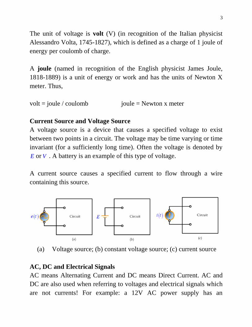
3
The unit of voltage is volt (V) (in recognition of the Italian physicist
Alessandro Volta 1745-1827) which is defined as a charge of 1 joule of
energy per coulomb of charge
A joule (named in recognition of the English physicist James Joule
1818-1889) is a unit of energy or work and has the units of Newton X
meter Thus
volt = joule coulomb joule = Newton x meter
Current Source and Voltage Source
A voltage source is a device that causes a specified voltage to exist
between two points in a circuit The voltage may be time varying or time
invariant (for a sufficiently long time) Often the voltage is denoted by
E or V A battery is an example of this type of voltage
A current source causes a specified current to flow through a wire
containing this source
(a) Voltage source (b) constant voltage source (c) current source
AC DC and Electrical Signals
AC means Alternating Current and DC means Direct Current AC and
DC are also used when referring to voltages and electrical signals which
are not currents For example a 12V AC power supply has an
4
alternating voltage (which will make an alternating current flow) An
electrical signal is a voltage or current which conveys information
usually it means a voltage The term can be used for any voltage or
current in a circuit
Direct Current (DC)
Direct Current (DC) always flows in the same directionbut it may
increase and decrease A DC voltage is always positive (or always
negative)but it may increase and decrease Electronic circuits normally
require a steady DC supply which is constant at one value or a smooth
DC supply which has a small variation called ripple Cells batteries and
regulated power supplies provide steady DC which is ideal for electronic
circuits
Power supplies contain a transformer which converts the mains AC
supply to a safe low voltage AC Then the ACis converted to DC by a
bridge rectifier but the output is varying DC which is unsuitable for
electronic circuits Some power supplies include a capacitor to provide
smooth DC which is suitable for less-sensitive electronic circuits
including most of the projects on this website Lamps heaters and
motors will work with any DC supply
5
Alternating Current (AC)
Alternating Current (AC) flow one way then the other way continually
reversing direction An AC voltage is continually changing between
positive (+) and negative (-)
The rate of changing direction is called the frequency of the AC and it is
measured in hertz (Hz) which is the number of forwards-backwards
cycles per second
Mains electricity in the USA and Canada has a frequency 60 Hz while
other counties have a frequency of 50 Hz
An AC supply is suitable for powering some devices such as lamps and
heaters but almost all electronic circuits require a steady DC supply
13 Properties of electrical signals
6
Amplitude is the maximum voltage reached by the signal
It is measured in volts V
Peak voltage is another name for amplitude
Peak-peak voltage is twice the peak voltage (amplitude) When
reading an oscilloscope trace it is usual to measure peak-peak
voltage
Time period is the time taken for the signal to complete one cycle
It is measured in seconds (s) but time periods tend to be short so
milliseconds (ms)= 10 -3
s and microseconds (micros)10 -6
s
Frequency is the number of cycles per second
It is measured in hertz (Hz)
1 kilohertz (kHz) =1000 Hz and megahertz (MHz) =106 Hz
Frequency = 1 time periodamptime period = 1 frequency
Mains electricity in the Egypt has a frequency of 50Hz
so it has a time period of 150 = 002s = 20ms
14 Root Mean Square (RMS) Values
The value of an AC voltage is
continually changing from zero up to the
positive peak through zero to the
negative peak and back to zero again
Clearly for most of the time it is less than
the peak voltage so this is not a good
measure of its real effect
Instead we use the root mean square voltage (VRMS) which is 07 of the
peak voltage (Vpeak)
VRMS = 07 times Vpeak and Vpeak = 14 times VRMS
7
These equations also apply to current They are only true for sine
waves (the most common type of AC) because the 07 and 14 are
different values for other shapes
The RMS value is the effective value of a varying voltage or current
It is the equivalent steady DC (constant) value which gives the same
effect
What do AC meters show is it the RMS or peak voltage
AC voltmeters and ammeters show the RMS value of the voltage or
current DC meters also show the RMS value when connected to varying
DC providing the DC is varying quickly if the frequency is less than
about 10Hz you will see the meter reading fluctuating instead
Electrical Resistance
Electrical resistance is a measure of the degree to which an object
opposes an electric current through it Its reciprocal quantity is electrical
conductance (provided the electrical impedance is real) measured in
siemens Assuming a uniform current density an objects electrical
resistance is a function of both its physical geometry and the resistivity
of the material it is made from
A
lR
where
is the length
A is the cross sectional area and
ρ is the resistivity of the material
Electrical resistance shares some conceptual parallels with the
mechanical notion of friction The SI unit of electrical resistance is the
ohm symbol Ω
The electrical resistivity ρ (rho) of a material is given by
8
l
RA
Where ρ is the static resistivity (measured in ohm metres Ω-m)
R is the electrical resistance of a uniform specimen of the
material (measured in ohms Ω)
is the length of the piece of material (measured in metres m)
A is the cross-sectional area of the specimen (measured in
square metres msup2)
Electrical resistivity can also be defined as
J
E
Where E is the magnitude of the electric field (measured in volts per
metre Vm)
J is the magnitude of the current density (measured in amperes
per square metre Amsup2)
The conductivityσ (sigma) is defined as the inverse of the electrical
resistivity of the material or
1
Example
What is the value of the resistance of a copper wire with length 250m
and cross section area equals 25 mmsup2
Solution
Plug into the formula and using the value of the resistivity of the copper
from the table
A
lR
9
7211052
25010 x 1726
-8
x
xR
Ohms law
Ohms lawstates that in an electrical circuit the current passing through
a conductor between two points is directly proportional to the potential
difference (ie voltage drop or voltage) across the two points and
inversely proportional to the resistance between them and for the same
temperature
The mathematical equation that describes this relationship is
R
VI
Where I is the current in amperes (A) V is the potential difference
between two points of interest in volts (V) and R is the resistance it
measured in ohms (which is equivalent to volts per ampere)
The potential difference is also known as the voltage drop and is
sometimes denoted by U E or emf (electromotive force) instead of V
Example
Suppose the ammeter reads 52 A and the voltmeter indicates 233 kV
What is the resistance
Solution
Convert to amperes and volts getting I = 0000052 A and E = 2330 V
Then plug into the formula
R = 23300000052 = 45000000 = 45 M
Example
Find V when I = 120nA and R = 25 k
10
Solution
Convert to amperes and ohms getting 910120 x A and R = 31025 x
Then plug into the formula
mVxxxxRIV 3103102510120 339
Example
Find I when V = 22kV and R = 440
Solution
Using Ohms Law Eq
Ax
R
VI 50
440
1022 3
Electrical Power
The electric power P used in any part of a circuit is equal to the current I
in that part multiplied by the voltage V across that part of the circuit Its
formula is
P = VI
Where P = power W
V = voltage V
I = current A
If we know the current I and the resistance R but not the voltage V we
can find the power P by using Ohm‟s law for voltage so that
substituting V = IR
RIP 2
In the same manner if we know the voltage V and the resistance R but
not the current I we can find the power P by using Ohm‟s law for
current so that substitutingR
VI
11
R
VP
2
Example
The current through a 100Ω resistor to be used in a circuit is 020 A
Find the power rating of the resistor
Solution
WxRIP 410020 22
Example
If the voltage across a 25000 Ω resistor is 500 V what is the power
dissipated in the resistor
Solution
WR
VP 10
25000
500 22
19 Electrical energy
Electrical energy in any part of the circuit is that power of that part
multiplied of the time of consumption and it can be found from the
formula
Electrical energy U = Power x time
U =VIt (Joules)
Kilowatt hour (kWh)= 1000 watt hour
= 1000 x 3600 watt seconds or joule = 3 600 000 J
Example
A source emf of 5 V is supplies a current of 3 A for 10 minutes How
much energy is provided in this time
12
Solution
Energy = power x time power = voltage x current
U = VIt = 5 x 3 x (10 x 60) = 9000 Ws or J
= 9 kJ
Example
An electric heater consumes 18 MJ when connected to a 250 V supply
for 30 minutes Find the power rating of the heater and the current taken
from the supply
Solution
Power rating of heater = kWWx
x
t
UP 11000
6030
1081 6
Thus AV
PI 4
250
1000
Example
An electric bulb has a power 100 W If it works 10 hours per day find
the energy consumed in 1 month
Solution
Since energy = power x time
Then Energy U = P x t = 100 x 10 x 30
= 30000 Wh= 30 kWh
Series and Parallel Networks
Series circuits
TheFigure shows three resistors R1 R2 and R3 connected end to end
ie in series with a battery source of V volts Since the circuitis closed
13
a current I will flow and the pd across eachresistor may be determined
from the voltmeter readings V1 V2 and V3
In a series circuit
(a) the current I is the same in all parts of the circuit and hence the same
reading is found on each of the two ammeters shown and
(b) the sum of the voltages V1 V2 and V3 is equal to the total applied
voltage V ie
From Ohm‟s law
where R is the total circuit resistance
Since V = V1 + V2 + V3
then IR = IR1 + IR2 + IR3
Dividing throughout by I gives
Thus for a series circuit the total resistance is obtained by adding
together the values of the separate resistances
Example 113 For the circuit shown in the illustrated figure determine
(a) the battery voltage V
(b) the total resistance of the circuit and
(c) the values of resistance of resistors R1 R2 and R3 given
that the pd‟s across R1 R2 and R3 are 5 V 2 V and 6 V respectively
14
Solution
Voltage divider
The voltage distribution for the circuit shown in the Figure is given by
15
Example
Two resistors are connected in seriesacross a 24 V supply and a current
of 3 A flows in thecircuit If one of the resistors has a resistance of 2 Ω
determine (a) the value of the other resistor and
(b) the difference across the 2 Ω resistor
Solution
(a) Total circuit resistance
Value of unknown resistance
(b) Volt Difference across 2 Ω resistor V1 = IR1 = 3 x 2 = 6 V
Alternatively from above
Parallel networks
The Figure shows three resistorsR1 R2 and R3 connected across each
other iein parallel across a battery source of V volts
16
In a parallel circuit
(a) the sum of the currents I1 I2 and I3 is equal to the total
circuitcurrent I ie I = I1 + I2 + I3 and
(b) the source pdis the same across each of the resistors
From Ohm‟s law
where R is the total circuit resistance
Since I = I1 + I2 + I3
Dividing throughout by V gives
This equation must be used when finding the total resistance R of a
parallel circuit
For the special case of two resistors in parallel
17
Example
For the circuit shown in the Figure find
(a) the value of the supply voltage V
(b) the value of current I
Solution
(a) Vd across 20 Ω resistor = I2R2 = 3 x 20 = 60 V hencesupply
voltage V = 60 V since the circuit is connected in parallel
Current I = I1 + I2 + I3 = 6 + 3 + 1 = 10 A
Another solution for part (b)
18
Current division
For the circuit shown in the Figure the total circuit resistance RT
isgiven by
Example
For the circuit shown in the Figure find the current Ix
Solution
19
Commencing at the right-hand side of the arrangement shown in the
Figure below the circuit is gradually reduced in stages as shown in
Figure (a)ndash(d)
From Figure (d)
From Figure (b)
From the above Figure
Kirchhoffrsquos laws
Kirchhoffrsquos laws state
20
(a) Current Law At any junction in an electric circuit the total
current flowing towards that junction is equal to the total current
flowing away from the junction ie sumI = 0
Thus referring to Figure 21
I1 + I2 = I3 + I4 + I5 I1 + I2 - I3 - I4 - I5 = 0
(b) Voltage Law In any closed loop in a network the algebraic sum
of the voltage drops (ie products ofcurrent and resistance) taken
around the loop is equal to the resultant emf acting in that loop
Thus referring to Figure 22
E1 - E2 = IR1 + IR2 + IR3
(Note that if current flows away from the positive terminal of a source
that source is considered by convention to be positive Thus moving
anticlockwise around the loop of Figure 22 E1 is positive and E2 is
negative)
21
Example
Find the unknown currents marked in the following Figure
Solution
Applying Kirchhoff‟s current law
For junction B 50 = 20 + I1 hence I1 = 30 A
For junction C 20 + 15 = I2 hence I2 = 35 A
For junction D I1 = I3 + 120 hence I3 = minus90 A
(the current I3 in the opposite direction to that shown in the Figure)
For junction EI4 + I3 = 15 hence I4 = 105 A
For junction F 120 = I5 + 40 hence I5 = 80 A
Example
Determine the value of emf E in the following Figure
22
Solution
Applying Kirchhoff‟s voltage law
Starting at point A and moving clockwise around the loop
3 + 6 + E - 4 = (I)(2) + (I)(25) + (I)(15) + (I)(1)
5 + E = I (7)
Since I = 2 A hence E = 9 V
Example
Use Kirchhoff‟s laws to determine the currents flowing in each branch
of the network shown in Figure 24
23
Solution
1 Divide the circuit into two loops The directions current flows from
the positive terminals of the batteries The current through R is I1 + I2
2 Apply Kirchhoff‟s voltage law foreach loop
By moving in a clockwise direction for loop 1 of Figure 25
(1)
By moving in an anticlockwise direction for loop 2 of Figure 25
(2)
3 Solve equations (1) and (2) for I1 and I2
(3)
(4)
(ie I2 is flowing in the opposite direction to that shown in Figure 25)
From (1)
Current flowing through resistance R is
Note that a third loop is possible as shown in Figure 26giving a third
equation which can be used as a check
24
Example
Determine using Kirchhoff‟s laws each branch current for the network
shown in Figure 27
Solution
1 The network is divided into two loops as shown in Figure 28 Also
the directions current are shown in this Figure
2 Applying Kirchhoff‟s voltage law gives
For loop 1
(1)
25
For loop 2
(2)
(Note that the opposite direction of current in loop 2)
3 Solving equations (1) and (2) to find I1 and I2
(3)
(2) + (3) give
From (1)
Current flowing in R3 = I1-I2 = 652 ndash 637 = 015 A
Example
For the bridge network shown in Figure 29 determine the currents in
each of the resistors
26
Solution
- Let the current in the 2Ω resistor be I1 and then by Kirchhoff‟s current
law the current in the 14 Ω resistor is (I - I1)
- Let thecurrent in the 32 Ω resistor be I2 Then the current in the 11
resistor is (I1 - I2) and that in the3 Ω resistor is (I - I1 + I2)
- Applying Kirchhoff‟s voltage law to loop 1 and moving in a clockwise
direction
(1)
- Applying Kirchhoff‟s voltage law to loop 2 and moving in an
anticlockwise direction
(2)
Solve Equations (1) and (2) to calculate I1 and I2
(3)
(4)
(4) ndash (3) gives
Substituting for I2 in (1) gives
27
Hence
the current flowing in the 2 Ω resistor = I1 = 5 A
the current flowing in the 14 Ω resistor = I - I1 = 8 - 5 = 3 A
the current flowing in the 32 Ω resistor = I2 = 1 A
the current flowing in the 11 Ω resistor = I1 - I2 = 5 - 1 = 4 Aand
the current flowing in the 3 Ω resistor = I - I1 + I2 = 8 - 5 + 1 = 4 A
The Superposition Theorem
The superposition theorem statesIn any network made up of linear
resistances and containing more than one source of emf the resultant
current flowing in any branch is the algebraic sum of the currents that
would flow in that branch if each source was considered separately all
other sources being replaced at that time by their respective internal
resistances‟
Example
Figure 211 shows a circuit containing two sources of emf each with
their internal resistance Determine the current in each branch of the
network by using the superposition theorem
28
Solution Procedure
1 Redraw the original circuit with source E2 removed being replaced
by r2 only as shown in Figure (a)
2 Label the currents in each branch and their directions as shown
inFigure (a) and determine their values (Note that the choice of current
directions depends on the battery polarity which flowing from the
positive battery terminal as shown)
R in parallel with r2 gives an equivalent resistance of
From the equivalent circuit of Figure (b)
From Figure (a)
29
3 Redraw the original circuit with source E1 removed being replaced
by r1 only as shown in Figure (aa)
4 Label the currents in each branch and their directions as shown
inFigure (aa) and determine their values
r1 in parallel with R gives an equivalent resistance of
From the equivalent circuit of Figure (bb)
From Figure (aa)
By current divide
5 Superimpose Figure (a) on to Figure (aa) as shown in Figure 213
30
6 Determine the algebraic sum of the currents flowing in each branch
Resultant current flowing through source 1
Resultant current flowing through source 2
Resultant current flowing through resistor R
The resultant currents with their directions are shown in Figure 214
Theveninrsquos Theorem
Thevenin‟s theorem statesThe current in any branch of a network is that
which would result if an emf equal to the pd across a break made in
the branch were introduced into the branch all other emf‟s being
removed and represented by the internal resistances of the sources‟
31
The procedure adopted when using Thevenin‟s theorem is summarized
below
To determine the current in any branch of an active network (ie one
containing a source of emf)
(i) remove the resistance R from that branch
(ii) determine the open-circuit voltage E across the break
(iii) remove each source of emf and replace them by their internal
resistances and then determine the resistance r bdquolooking-in‟ at the break
(iv) determine the value of the current from the equivalent circuit
shownin Figure 216 ie
Example
Use Thevenin‟s theorem to find the current flowing in the 10 Ω resistor
for the circuit shown in Figure 217
32
Solution
Following the above procedure
(i) The 10Ω resistance is removed from the circuit as shown in Figure
218
(ii) There is no current flowing in the 5 Ωresistor and current I1 is given
by
Pd across R2 = I1R2 = 1 x 8 = 8 V
Hence pd across AB ie the open-circuit voltage across the break
E = 8 V
(iii) Removing the source of emf gives the circuit of Figure 219
Resistance
(iv) The equivalent Thacuteevenin‟s circuit is shown in Figure 220
Current
33
Hence the current flowing in the 10 resistor of Figure 217 is 0482 A
Example
A Wheatstone Bridge network is shown in Figure 221(a) Calculate the
current flowing in the 32Ω resistorand its direction using Thacuteevenin‟s
theorem Assume the source ofemf to have negligible resistance
Solution
Following the procedure
(i) The 32Ω resistor is removed from the circuit as shown in Figure
221(b)
(ii) The pd between A and C
34
The pd between B and C
Hence
Voltage between A and B is VAB= VAC ndash VBC = 3616 V
Voltage at point C is +54 V
Voltage between C and A is 831 V
Voltage at point A is 54 - 831 = 4569 V
Voltage between C and B is 4447 V
Voltage at point B is 54 - 4447 = 953 V
Since the voltage at A is greater than at B current must flow in the
direction A to B
(iii) Replacing the source of emf with short-circuit (ie zero internal
resistance) gives the circuit shown in Figure 221(c)
The circuit is redrawn and simplified as shown in Figure 221(d) and (e)
fromwhich the resistance between terminals A and B
(iv) The equivalent Thacuteevenin‟s circuit is shown in Figure 1332(f) from
whichCurrent
35
Hence the current in the 32 Ω resistor of Figure 221(a) is 1 A
flowing from A to B
Example
Use Thacuteevenin‟s theorem to determine the currentflowing in the 3 Ω
resistance of the network shown inFigure 222 The voltage source has
negligible internalresistance
Solution
Following the procedure
(i) The 3 Ω resistance is removed from the circuit as shown inFigure
223
(ii) The Ω resistance now carries no current
36
Hence pd across AB E = 16 V
(iii) Removing the source of emf and replacing it by its internal
resistance means that the 20 Ω resistance is short-circuited as shown in
Figure 224 since its internal resistance is zero The 20 Ω resistance may
thus be removed as shown in Figure 225
From Figure 225 Thacuteevenin‟s resistance
(iv)The equivalent Thevenin‟s circuit is shown in Figure 226
Nortonrsquos Theorem
Norton‟s theorem statesThe current that flows in any branch of a
network is the same as that which would flow in the branch if it were
connected across a source of electrical energy the short-circuit current
of which is equal to the current that would flow in a short-circuit across
the branch and the internal resistance of which is equal to the resistance
which appears across the open-circuited branch terminals‟
The procedure adopted when using Norton‟s theorem is summarized
below
To determine the current flowing in a resistance R of a branch AB of an
active network
(i) short-circuit branch AB
37
(ii) determine the short-circuit current ISC flowing in the branch
(iii) remove all sources of emf and replace them by their internal
resistance (or if a current source exists replace with an open circuit)
then determine the resistance rbdquolooking-in‟ at a break made between A
and B
(iv) determine the current I flowing in resistance R from the Norton
equivalent network shown in Figure 1226 ie
Example
Use Norton‟s theorem to determine the current flowing in the 10
Ωresistance for the circuit shown in Figure 227
38
Solution
Following the procedure
(i) The branch containing the 10 Ωresistance is short-circuited as shown
in Figure 228
(ii) Figure 229 is equivalent to Figure 228 Hence
(iii) If the 10 V source of emf is removed from Figure 229 the
resistance bdquolooking-in‟ at a break made between A and B is given by
(iv) From the Norton equivalent network shown in Figure 230 the
current in the 10 Ω resistance by current division is given by
39
As obtained previously in above example using Thacuteevenin‟s theorem
Example
Use Norton‟s theorem to determine the current flowing in the 3
resistance of the network shown in Figure 231(a) The voltage source
has negligible internal resistance
Solution
Following the procedure
(i) The branch containing the 3 resistance is short-circuited as shown in
Figure 231(b)
(ii) From the equivalent circuit shown in Figure 231(c)
40
(iii) If the 24 V source of emf is removed the resistance bdquolooking-in‟ at
a break made between A and B is obtained from Figure 231(d) and its
equivalent circuit shown in Figure 231(e) and is given by
(iv) From the Norton equivalent network shown in Figure 231(f) the
current in the 3 Ωresistance is given by
As obtained previously in previous example using Thevenin‟s theorem
Extra Example
Use Kirchhoffs Laws to find the current in each resistor for the circuit in
Figure 232
Solution
1 Currents and their directions are shown in Figure 233 following
Kirchhoff‟s current law
41
Applying Kirchhoff‟s current law
For node A gives 314 III
For node B gives 325 III
2 The network is divided into three loops as shown in Figure 233
Applying Kirchhoff‟s voltage law for loop 1 gives
41 405015 II
)(405015 311 III
31 8183 II
Applying Kirchhoff‟s voltage law for loop 2 gives
52 302010 II
)(302010 322 III
32 351 II
Applying Kirchhoff‟s voltage law for loop 3 gives
453 4030250 III
)(40)(30250 31323 IIIII
321 19680 III
42
Arrange the three equations in matrix form
0
1
3
1968
350
8018
3
2
1
I
I
I
10661083278568
0183
198
8185
1968
350
8018
xx
183481773196
801
196
353
1960
351
803
1
xx
206178191831
838
190
3118
1908
310
8318
2
xx
12618140368
0181
68
503
068
150
3018
3
xxx
17201066
18311
I A
19301066
20622
I A
01101066
1233
I A
43
1610011017204 I A
1820011019305 I A
Star Delta Transformation
Star Delta Transformations allow us to convert impedances connected
together from one type of connection to another We can now solve
simple series parallel or bridge type resistive networks using
Kirchhoff‟s Circuit Laws mesh current analysis or nodal voltage
analysis techniques but in a balanced 3-phase circuit we can use
different mathematical techniques to simplify the analysis of the circuit
and thereby reduce the amount of math‟s involved which in itself is a
good thing
Standard 3-phase circuits or networks take on two major forms with
names that represent the way in which the resistances are connected a
Star connected network which has the symbol of the letter Υ and a
Delta connected network which has the symbol of a triangle Δ (delta)
If a 3-phase 3-wire supply or even a 3-phase load is connected in one
type of configuration it can be easily transformed or changed it into an
equivalent configuration of the other type by using either the Star Delta
Transformation or Delta Star Transformation process
A resistive network consisting of three impedances can be connected
together to form a T or ldquoTeerdquo configuration but the network can also be
redrawn to form a Star or Υ type network as shown below
T-connected and Equivalent Star Network
44
As we have already seen we can redraw the T resistor network to
produce an equivalent Star or Υ type network But we can also convert
a Pi or π type resistor network into an equivalent Delta or Δ type
network as shown below
Pi-connected and Equivalent Delta Network
Having now defined exactly what is a Star and Delta connected network
it is possible to transform the Υ into an equivalent Δ circuit and also to
convert a Δ into an equivalent Υ circuit using a the transformation
process This process allows us to produce a mathematical relationship
between the various resistors giving us a Star Delta Transformation as
well as a Delta Star Transformation
45
These Circuit Transformations allow us to change the three connected
resistances (or impedances) by their equivalents measured between the
terminals 1-2 1-3 or 2-3 for either a star or delta connected circuit
However the resulting networks are only equivalent for voltages and
currents external to the star or delta networks as internally the voltages
and currents are different but each network will consume the same
amount of power and have the same power factor to each other
Delta Star Transformation
To convert a delta network to an equivalent star network we need to
derive a transformation formula for equating the various resistors to each
other between the various terminals Consider the circuit below
Delta to Star Network
Compare the resistances between terminals 1 and 2
Resistance between the terminals 2 and 3
46
Resistance between the terminals 1 and 3
This now gives us three equations and taking equation 3 from equation 2
gives
Then re-writing Equation 1 will give us
Adding together equation 1 and the result above of equation 3 minus
equation 2 gives
47
From which gives us the final equation for resistor P as
Then to summarize a little about the above maths we can now say that
resistor P in a Star network can be found as Equation 1 plus (Equation 3
minus Equation 2) or Eq1 + (Eq3 ndash Eq2)
Similarly to find resistor Q in a star network is equation 2 plus the
result of equation 1 minus equation 3 or Eq2 + (Eq1 ndash Eq3) and this
gives us the transformation of Q as
and again to find resistor R in a Star network is equation 3 plus the
result of equation 2 minus equation 1 or Eq3 + (Eq2 ndash Eq1) and this
gives us the transformation of R as
When converting a delta network into a star network the denominators
of all of the transformation formulas are the same A + B + C and which
is the sum of ALL the delta resistances Then to convert any delta
connected network to an equivalent star network we can summarized the
above transformation equations as
48
Delta to Star Transformations Equations
If the three resistors in the delta network are all equal in value then the
resultant resistors in the equivalent star network will be equal to one
third the value of the delta resistors giving each branch in the star
network as RSTAR = 13RDELTA
Delta ndash Star Example No1
Convert the following Delta Resistive Network into an equivalent Star
Network
Star Delta Transformation
Star Delta transformation is simply the reverse of above We have seen
that when converting from a delta network to an equivalent star network
that the resistor connected to one terminal is the product of the two delta
resistances connected to the same terminal for example resistor P is the
product of resistors A and B connected to terminal 1
49
By rewriting the previous formulas a little we can also find the
transformation formulas for converting a resistive star network to an
equivalent delta network giving us a way of producing a star delta
transformation as shown below
Star to Delta Transformation
The value of the resistor on any one side of the delta Δ network is the
sum of all the two-product combinations of resistors in the star network
divide by the star resistor located ldquodirectly oppositerdquo the delta resistor
being found For example resistor A is given as
with respect to terminal 3 and resistor B is given as
with respect to terminal 2 with resistor C given as
with respect to terminal 1
By dividing out each equation by the value of the denominator we end
up with three separate transformation formulas that can be used to
convert any Delta resistive network into an equivalent star network as
given below
50
Star Delta Transformation Equations
Star Delta Transformation allows us to convert one type of circuit
connection into another type in order for us to easily analyse the circuit
and star delta transformation techniques can be used for either
resistances or impedances
One final point about converting a star resistive network to an equivalent
delta network If all the resistors in the star network are all equal in value
then the resultant resistors in the equivalent delta network will be three
times the value of the star resistors and equal giving RDELTA = 3RSTAR
Maximum Power Transfer
In many practical situations a circuit is designed to provide power to a
load While for electric utilities minimizing power losses in the process
of transmission and distribution is critical for efficiency and economic
reasons there are other applications in areas such as communications
where it is desirable to maximize the power delivered to a load We now
address the problem of delivering the maximum power to a load when
given a system with known internal lossesIt should be noted that this
will result in significant internal losses greater than or equal to the power
delivered to the load
The Thevenin equivalent is useful in finding the maximum power a
linear circuit can deliver to a load We assume that we can adjust the
load resistance RL If the entire circuit is replaced by its Thevenin
equivalent except for the load as shown the power delivered to the load
is
51
For a given circuit V Th and R Th are fixed Make a sketch of the power
as a function of load resistance
To find the point of maximum power transfer we differentiate p in the
equation above with respect to RL and set the result equal to zero Do
this to Write RL as a function of Vth and Rth
For maximum power transfer
ThL
L
RRdR
dPP 0max
Maximum power is transferred to the load when the load resistance
equals the Thevenin resistance as seen from the load (RL = RTh)
The maximum power transferred is obtained by substituting RL = RTh
into the equation for power so that
52
RVpRR
Th
Th
ThL 4
2
max
AC Resistor Circuit
If a resistor connected a source of alternating emf the current through
the resistor will be a function of time According to Ohm‟s Law the
voltage v across a resistor is proportional to the instantaneous current i
flowing through it
Current I = V R = (Vo R) sin(2πft) = Io sin(2πft)
The current passing through the resistance independent on the frequency
The current and the voltage are in the same phase
53
Capacitor
A capacitor is a device that stores charge It usually consists of two
conducting electrodes separated by non-conducting material Current
does not actually flow through a capacitor in circuit Instead charge
builds up on the plates when a potential is applied across the electrodes
The maximum amount of charge a capacitor can hold at a given
potential depends on its capacitance It can be used in electronics
communications computers and power systems as the tuning circuits of
radio receivers and as dynamic memory elements in computer systems
Capacitance is the ability to store an electric charge It is equal to the
amount of charge that can be stored in a capacitor divided by the voltage
applied across the plates The unit of capacitance is the farad (F)
V
QCVQ
where C = capacitance F
Q = amount of charge Coulomb
V = voltage V
54
The farad is that capacitance that will store one coulomb of charge in the
dielectric when the voltage applied across the capacitor terminals is one
volt (Farad = Coulomb volt)
Types of Capacitors
Commercial capacitors are named according to their dielectric Most
common are air mica paper and ceramic capacitors plus the
electrolytic type Most types of capacitors can be connected to an
electric circuit without regard to polarity But electrolytic capacitors and
certain ceramic capacitors are marked to show which side must be
connected to the more positive side of a circuit
Three factors determine the value of capacitance
1- the surface area of the plates ndash the larger area the greater the
capacitance
2- the spacing between the plates ndash the smaller the spacing the greater
the capacitance
3- the permittivity of the material ndash the higher the permittivity the
greater the capacitance
d
AC
where C = capacitance
A = surface area of each plate
d = distance between plates
= permittivity of the dielectric material between plates
According to the passive sign convention current is considered to flow
into the positive terminal of the capacitor when the capacitor is being
charged and out of the positive terminal when the capacitor is
discharging
55
Symbols for capacitors a) fixed capacitor b) variable capacitor
Current-voltage relationship of the capacitor
The power delivered to the capacitor
dt
dvCvvip
Energy stored in the capacitor
2
2
1vCw
Capacitors in Series and Parallel
Series
When capacitors are connected in series the total capacitance CT is
56
nT CCCCC
1
1111
321
Parallel
nT CCCCC 321
Capacitive Reactance
Capacitive reactance Xc is the opposition to the flow of ac current due to
the capacitance in the circuit The unit of capacitive reactance is the
ohm Capacitive reactance can be found by using the equation
fCXC
2
1
Where Xc= capacitive reactance Ω
f = frequency Hz
C= capacitance F
57
For DC the frequency = zero and hence Xc = infin This means the
capacitor blocking the DC current
The capacitor takes time for charge to build up in or discharge from a
capacitor there is a time lag between the voltage across it and the
current in the circuit We say that the current and the voltage are out of
phase they reach their maximum or minimum values at different times
We find that the current leads the capacitor voltage by a quarter of a
cycle If we associate 360 degrees with one full cycle then the current
and voltage across the capacitor are out of phase by 90 degrees
Alternating voltage V = Vo sinωt
Charge on the capacitor q = C V = C Vo sinωt
58
Current I =dq
dt= ω C Vo cosωt = Io sin(ωt +
π
2)
Note Vo
Io=
1
ω C= XC
The reason the current is said to lead the voltage is that the equation for
current has the term + π2 in the sine function argument t is the same
time in both equations
Example
A 120 Hz 25 mA ac current flows in a circuit containing a 10 microF
capacitor What is the voltage drop across the capacitor
Solution
Find Xc and then Vc by Ohms law
513210101202
1
2
16xxxxfC
XC
VxxIXV CCC 31310255132 3
Inductor
An inductor is simply a coil of conducting wire When a time-varying
current flows through the coil a back emf is induced in the coil that
opposes a change in the current passing through the coil The coil
designed to store energy in its magnetic field It can be used in power
supplies transformers radios TVs radars and electric motors
The self-induced voltage VL = L dI
dt
Where L = inductance H
LV = induced voltage across the coil V
59
dI
dt = rate of change of current As
For DC dIdt = 0 so the inductor is just another piece of wire
The symbol for inductance is L and its unit is the henry (H) One henry
is the amount of inductance that permits one volt to be induced when the
current changes at the rate of one ampere per second
Alternating voltage V = Vo sinωt
Induced emf in the coil VL = L dI
dt
Current I = 1
L V dt =
1
LVo sinωt dt
= 1
ω LVo cos(ωt) = Io sin(ωt minus
π
2)
60
Note Vo
Io= ω L = XL
In an inductor the current curve lags behind the voltage curve by π2
radians (90deg) as the diagram above shows
Power delivered to the inductor
idt
diLvip
Energy stored
2
2
1iLw
Inductive Reactance
Inductive reactance XL is the opposition to ac current due to the
inductance in the circuit
fLX L 2
Where XL= inductive reactance Ω
f = frequency Hz
L= inductance H
XL is directly proportional to the frequency of the voltage in the circuit
and the inductance of the coil This indicates an increase in frequency or
inductance increases the resistance to current flow
Inductors in Series and Parallel
If inductors are spaced sufficiently far apart sothat they do not interact
electromagnetically with each other their values can be combined just
like resistors when connected together
Series nT LLLLL 321
61
Parallel nT LLLLL
1
1111
3211
Example
A choke coil of negligible resistance is to limit the current through it to
50 mA when 25 V is applied across it at 400 kHz Find its inductance
Solution
Find XL by Ohms law and then find L
5001050
253xI
VX
L
LL
mHHxxxxf
XL L 20101990
104002
500
2
3
3
62
Problem
(a) Calculate the reactance of a coil of inductance 032H when it is
connected to a 50Hz supply
(b) A coil has a reactance of 124 ohm in a circuit with a supply of
frequency 5 kHz Determine the inductance of the coil
Solution
(a)Inductive reactance XL = 2πfL = 2π(50)(032) = 1005 ohm
(b) Since XL = 2πfL inductance L = XL 2πf = 124 2π(5000) = 395 mH
Problem
A coil has an inductance of 40 mH and negligible resistance Calculate
its inductive reactance and the resulting current if connected to
(a) a 240 V 50 Hz supply and (b) a 100 V 1 kHz supply
Solution
XL = 2πfL = 2π(50)(40 x 10-3
) = 1257 ohm
Current I = V XL = 240 1257 = 1909A
XL = 2π (1000)(40 x 10-3) = 2513 ohm
Current I = V XL = 100 2513 = 0398A
63
RC connected in Series
By applying Kirchhoffs laws apply at any instant the voltage vs(t)
across a resistor and capacitor in series
Vs(t) = VR(t) + VC(t)
However the addition is more complicated because the two are not in
phase they add to give a new sinusoidal voltage but the amplitude VS is
less than VR + VC
Applying again Pythagoras theorem
RCconnected in Series
The instantaneous voltage vs(t) across the resistor and inductor in series
will be Vs(t) = VR(t) + VL(t)
64
And again the amplitude VRLS will be always less than VR + VL
Applying again Pythagoras theorem
RLC connected in Series
The instantaneous voltage Vs(t) across the resistor capacitor and
inductor in series will be VRCLS(t) = VR(t) + VC(t) + VL(t)
The amplitude VRCLS will be always less than VR + VC + VL
65
Applying again Pythagoras theorem
Problem
In a series RndashL circuit the pd across the resistance R is 12 V and the
pd across the inductance L is 5 V Find the supply voltage and the
phase angle between current and voltage
Solution
66
Problem
A coil has a resistance of 4 Ω and an inductance of 955 mH Calculate
(a) the reactance (b) the impedance and (c) the current taken from a 240
V 50 Hz supply Determine also the phase angle between the supply
voltage and current
Solution
R = 4 Ohm L = 955mH = 955 x 10_3 H f = 50 Hz and V = 240V
XL = 2πfL = 3 ohm
Z = R2 + XL2 = 5 ohm
I = V
Z= 48 A
The phase angle between current and voltage
tanϕ = XL
R=
3
5 ϕ = 3687 degree lagging
67
Problem
A coil takes a current of 2A from a 12V dc supply When connected to
a 240 V 50 Hz supply the current is 20 A Calculate the resistance
impedance inductive reactance and inductance of the coil
Solution
R = d c voltage
d c current=
12
2= 6 ohm
Z = a c voltage
a c current= 12 ohm
Since
Z = R2 + XL2
XL = Z2 minus R2 = 1039 ohm
Since XL = 2πfL so L =XL
2πf= 331 H
This problem indicates a simple method for finding the inductance of a
coil ie firstly to measure the current when the coil is connected to a
dc supply of known voltage and then to repeat the process with an ac
supply
Problem
A coil consists of a resistance of 100 ohm and an inductance of 200 mH
If an alternating voltage v given by V = 200 sin 500 t volts is applied
across the coil calculate (a) the circuit impedance (b) the current
flowing (c) the pd across the resistance (d) the pd across the
inductance and (e) the phase angle between voltage and current
Solution
Since V = 200 sin 500 t volts then Vm = 200V and ω = 2πf = 500 rads
68
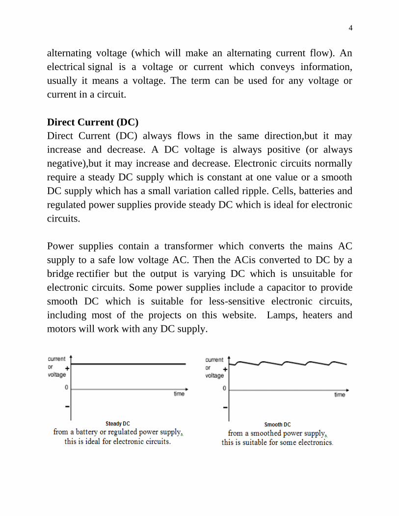
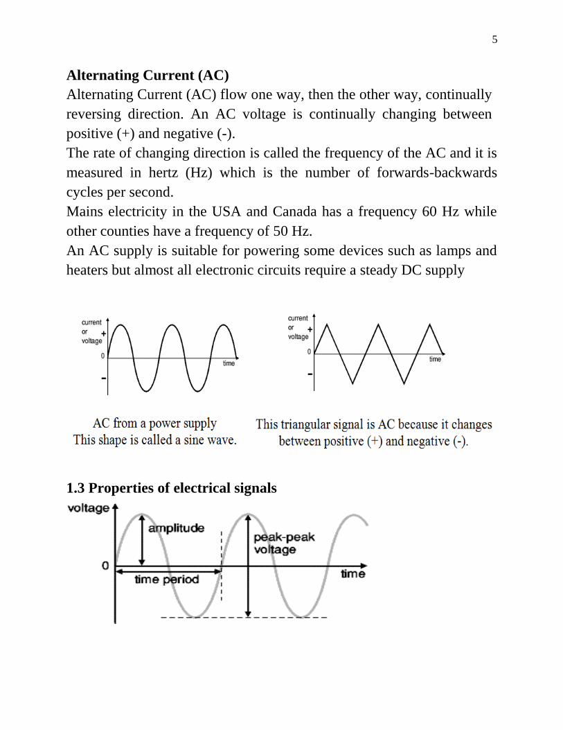
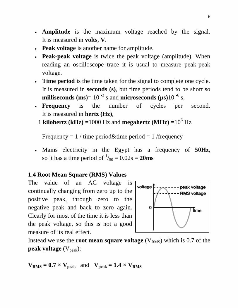
12
Solution
Energy = power x time power = voltage x current
U = VIt = 5 x 3 x (10 x 60) = 9000 Ws or J
= 9 kJ
Example
An electric heater consumes 18 MJ when connected to a 250 V supply
for 30 minutes Find the power rating of the heater and the current taken
from the supply
Solution
Power rating of heater = kWWx
x
t
UP 11000
6030
1081 6
Thus AV
PI 4
250
1000
Example
An electric bulb has a power 100 W If it works 10 hours per day find
the energy consumed in 1 month
Solution
Since energy = power x time
Then Energy U = P x t = 100 x 10 x 30
= 30000 Wh= 30 kWh
Series and Parallel Networks
Series circuits
TheFigure shows three resistors R1 R2 and R3 connected end to end
ie in series with a battery source of V volts Since the circuitis closed
13
a current I will flow and the pd across eachresistor may be determined
from the voltmeter readings V1 V2 and V3
In a series circuit
(a) the current I is the same in all parts of the circuit and hence the same
reading is found on each of the two ammeters shown and
(b) the sum of the voltages V1 V2 and V3 is equal to the total applied
voltage V ie
From Ohm‟s law
where R is the total circuit resistance
Since V = V1 + V2 + V3
then IR = IR1 + IR2 + IR3
Dividing throughout by I gives
Thus for a series circuit the total resistance is obtained by adding
together the values of the separate resistances
Example 113 For the circuit shown in the illustrated figure determine
(a) the battery voltage V
(b) the total resistance of the circuit and
(c) the values of resistance of resistors R1 R2 and R3 given
that the pd‟s across R1 R2 and R3 are 5 V 2 V and 6 V respectively
14
Solution
Voltage divider
The voltage distribution for the circuit shown in the Figure is given by
15
Example
Two resistors are connected in seriesacross a 24 V supply and a current
of 3 A flows in thecircuit If one of the resistors has a resistance of 2 Ω
determine (a) the value of the other resistor and
(b) the difference across the 2 Ω resistor
Solution
(a) Total circuit resistance
Value of unknown resistance
(b) Volt Difference across 2 Ω resistor V1 = IR1 = 3 x 2 = 6 V
Alternatively from above
Parallel networks
The Figure shows three resistorsR1 R2 and R3 connected across each
other iein parallel across a battery source of V volts
16
In a parallel circuit
(a) the sum of the currents I1 I2 and I3 is equal to the total
circuitcurrent I ie I = I1 + I2 + I3 and
(b) the source pdis the same across each of the resistors
From Ohm‟s law
where R is the total circuit resistance
Since I = I1 + I2 + I3
Dividing throughout by V gives
This equation must be used when finding the total resistance R of a
parallel circuit
For the special case of two resistors in parallel
17
Example
For the circuit shown in the Figure find
(a) the value of the supply voltage V
(b) the value of current I
Solution
(a) Vd across 20 Ω resistor = I2R2 = 3 x 20 = 60 V hencesupply
voltage V = 60 V since the circuit is connected in parallel
Current I = I1 + I2 + I3 = 6 + 3 + 1 = 10 A
Another solution for part (b)
18
Current division
For the circuit shown in the Figure the total circuit resistance RT
isgiven by
Example
For the circuit shown in the Figure find the current Ix
Solution
19
Commencing at the right-hand side of the arrangement shown in the
Figure below the circuit is gradually reduced in stages as shown in
Figure (a)ndash(d)
From Figure (d)
From Figure (b)
From the above Figure
Kirchhoffrsquos laws
Kirchhoffrsquos laws state
20
(a) Current Law At any junction in an electric circuit the total
current flowing towards that junction is equal to the total current
flowing away from the junction ie sumI = 0
Thus referring to Figure 21
I1 + I2 = I3 + I4 + I5 I1 + I2 - I3 - I4 - I5 = 0
(b) Voltage Law In any closed loop in a network the algebraic sum
of the voltage drops (ie products ofcurrent and resistance) taken
around the loop is equal to the resultant emf acting in that loop
Thus referring to Figure 22
E1 - E2 = IR1 + IR2 + IR3
(Note that if current flows away from the positive terminal of a source
that source is considered by convention to be positive Thus moving
anticlockwise around the loop of Figure 22 E1 is positive and E2 is
negative)
21
Example
Find the unknown currents marked in the following Figure
Solution
Applying Kirchhoff‟s current law
For junction B 50 = 20 + I1 hence I1 = 30 A
For junction C 20 + 15 = I2 hence I2 = 35 A
For junction D I1 = I3 + 120 hence I3 = minus90 A
(the current I3 in the opposite direction to that shown in the Figure)
For junction EI4 + I3 = 15 hence I4 = 105 A
For junction F 120 = I5 + 40 hence I5 = 80 A
Example
Determine the value of emf E in the following Figure
22
Solution
Applying Kirchhoff‟s voltage law
Starting at point A and moving clockwise around the loop
3 + 6 + E - 4 = (I)(2) + (I)(25) + (I)(15) + (I)(1)
5 + E = I (7)
Since I = 2 A hence E = 9 V
Example
Use Kirchhoff‟s laws to determine the currents flowing in each branch
of the network shown in Figure 24
23
Solution
1 Divide the circuit into two loops The directions current flows from
the positive terminals of the batteries The current through R is I1 + I2
2 Apply Kirchhoff‟s voltage law foreach loop
By moving in a clockwise direction for loop 1 of Figure 25
(1)
By moving in an anticlockwise direction for loop 2 of Figure 25
(2)
3 Solve equations (1) and (2) for I1 and I2
(3)
(4)
(ie I2 is flowing in the opposite direction to that shown in Figure 25)
From (1)
Current flowing through resistance R is
Note that a third loop is possible as shown in Figure 26giving a third
equation which can be used as a check
24
Example
Determine using Kirchhoff‟s laws each branch current for the network
shown in Figure 27
Solution
1 The network is divided into two loops as shown in Figure 28 Also
the directions current are shown in this Figure
2 Applying Kirchhoff‟s voltage law gives
For loop 1
(1)
25
For loop 2
(2)
(Note that the opposite direction of current in loop 2)
3 Solving equations (1) and (2) to find I1 and I2
(3)
(2) + (3) give
From (1)
Current flowing in R3 = I1-I2 = 652 ndash 637 = 015 A
Example
For the bridge network shown in Figure 29 determine the currents in
each of the resistors
26
Solution
- Let the current in the 2Ω resistor be I1 and then by Kirchhoff‟s current
law the current in the 14 Ω resistor is (I - I1)
- Let thecurrent in the 32 Ω resistor be I2 Then the current in the 11
resistor is (I1 - I2) and that in the3 Ω resistor is (I - I1 + I2)
- Applying Kirchhoff‟s voltage law to loop 1 and moving in a clockwise
direction
(1)
- Applying Kirchhoff‟s voltage law to loop 2 and moving in an
anticlockwise direction
(2)
Solve Equations (1) and (2) to calculate I1 and I2
(3)
(4)
(4) ndash (3) gives
Substituting for I2 in (1) gives
27
Hence
the current flowing in the 2 Ω resistor = I1 = 5 A
the current flowing in the 14 Ω resistor = I - I1 = 8 - 5 = 3 A
the current flowing in the 32 Ω resistor = I2 = 1 A
the current flowing in the 11 Ω resistor = I1 - I2 = 5 - 1 = 4 Aand
the current flowing in the 3 Ω resistor = I - I1 + I2 = 8 - 5 + 1 = 4 A
The Superposition Theorem
The superposition theorem statesIn any network made up of linear
resistances and containing more than one source of emf the resultant
current flowing in any branch is the algebraic sum of the currents that
would flow in that branch if each source was considered separately all
other sources being replaced at that time by their respective internal
resistances‟
Example
Figure 211 shows a circuit containing two sources of emf each with
their internal resistance Determine the current in each branch of the
network by using the superposition theorem
28
Solution Procedure
1 Redraw the original circuit with source E2 removed being replaced
by r2 only as shown in Figure (a)
2 Label the currents in each branch and their directions as shown
inFigure (a) and determine their values (Note that the choice of current
directions depends on the battery polarity which flowing from the
positive battery terminal as shown)
R in parallel with r2 gives an equivalent resistance of
From the equivalent circuit of Figure (b)
From Figure (a)
29
3 Redraw the original circuit with source E1 removed being replaced
by r1 only as shown in Figure (aa)
4 Label the currents in each branch and their directions as shown
inFigure (aa) and determine their values
r1 in parallel with R gives an equivalent resistance of
From the equivalent circuit of Figure (bb)
From Figure (aa)
By current divide
5 Superimpose Figure (a) on to Figure (aa) as shown in Figure 213
30
6 Determine the algebraic sum of the currents flowing in each branch
Resultant current flowing through source 1
Resultant current flowing through source 2
Resultant current flowing through resistor R
The resultant currents with their directions are shown in Figure 214
Theveninrsquos Theorem
Thevenin‟s theorem statesThe current in any branch of a network is that
which would result if an emf equal to the pd across a break made in
the branch were introduced into the branch all other emf‟s being
removed and represented by the internal resistances of the sources‟
31
The procedure adopted when using Thevenin‟s theorem is summarized
below
To determine the current in any branch of an active network (ie one
containing a source of emf)
(i) remove the resistance R from that branch
(ii) determine the open-circuit voltage E across the break
(iii) remove each source of emf and replace them by their internal
resistances and then determine the resistance r bdquolooking-in‟ at the break
(iv) determine the value of the current from the equivalent circuit
shownin Figure 216 ie
Example
Use Thevenin‟s theorem to find the current flowing in the 10 Ω resistor
for the circuit shown in Figure 217
32
Solution
Following the above procedure
(i) The 10Ω resistance is removed from the circuit as shown in Figure
218
(ii) There is no current flowing in the 5 Ωresistor and current I1 is given
by
Pd across R2 = I1R2 = 1 x 8 = 8 V
Hence pd across AB ie the open-circuit voltage across the break
E = 8 V
(iii) Removing the source of emf gives the circuit of Figure 219
Resistance
(iv) The equivalent Thacuteevenin‟s circuit is shown in Figure 220
Current
33
Hence the current flowing in the 10 resistor of Figure 217 is 0482 A
Example
A Wheatstone Bridge network is shown in Figure 221(a) Calculate the
current flowing in the 32Ω resistorand its direction using Thacuteevenin‟s
theorem Assume the source ofemf to have negligible resistance
Solution
Following the procedure
(i) The 32Ω resistor is removed from the circuit as shown in Figure
221(b)
(ii) The pd between A and C
34
The pd between B and C
Hence
Voltage between A and B is VAB= VAC ndash VBC = 3616 V
Voltage at point C is +54 V
Voltage between C and A is 831 V
Voltage at point A is 54 - 831 = 4569 V
Voltage between C and B is 4447 V
Voltage at point B is 54 - 4447 = 953 V
Since the voltage at A is greater than at B current must flow in the
direction A to B
(iii) Replacing the source of emf with short-circuit (ie zero internal
resistance) gives the circuit shown in Figure 221(c)
The circuit is redrawn and simplified as shown in Figure 221(d) and (e)
fromwhich the resistance between terminals A and B
(iv) The equivalent Thacuteevenin‟s circuit is shown in Figure 1332(f) from
whichCurrent
35
Hence the current in the 32 Ω resistor of Figure 221(a) is 1 A
flowing from A to B
Example
Use Thacuteevenin‟s theorem to determine the currentflowing in the 3 Ω
resistance of the network shown inFigure 222 The voltage source has
negligible internalresistance
Solution
Following the procedure
(i) The 3 Ω resistance is removed from the circuit as shown inFigure
223
(ii) The Ω resistance now carries no current
36
Hence pd across AB E = 16 V
(iii) Removing the source of emf and replacing it by its internal
resistance means that the 20 Ω resistance is short-circuited as shown in
Figure 224 since its internal resistance is zero The 20 Ω resistance may
thus be removed as shown in Figure 225
From Figure 225 Thacuteevenin‟s resistance
(iv)The equivalent Thevenin‟s circuit is shown in Figure 226
Nortonrsquos Theorem
Norton‟s theorem statesThe current that flows in any branch of a
network is the same as that which would flow in the branch if it were
connected across a source of electrical energy the short-circuit current
of which is equal to the current that would flow in a short-circuit across
the branch and the internal resistance of which is equal to the resistance
which appears across the open-circuited branch terminals‟
The procedure adopted when using Norton‟s theorem is summarized
below
To determine the current flowing in a resistance R of a branch AB of an
active network
(i) short-circuit branch AB
37
(ii) determine the short-circuit current ISC flowing in the branch
(iii) remove all sources of emf and replace them by their internal
resistance (or if a current source exists replace with an open circuit)
then determine the resistance rbdquolooking-in‟ at a break made between A
and B
(iv) determine the current I flowing in resistance R from the Norton
equivalent network shown in Figure 1226 ie
Example
Use Norton‟s theorem to determine the current flowing in the 10
Ωresistance for the circuit shown in Figure 227
38
Solution
Following the procedure
(i) The branch containing the 10 Ωresistance is short-circuited as shown
in Figure 228
(ii) Figure 229 is equivalent to Figure 228 Hence
(iii) If the 10 V source of emf is removed from Figure 229 the
resistance bdquolooking-in‟ at a break made between A and B is given by
(iv) From the Norton equivalent network shown in Figure 230 the
current in the 10 Ω resistance by current division is given by
39
As obtained previously in above example using Thacuteevenin‟s theorem
Example
Use Norton‟s theorem to determine the current flowing in the 3
resistance of the network shown in Figure 231(a) The voltage source
has negligible internal resistance
Solution
Following the procedure
(i) The branch containing the 3 resistance is short-circuited as shown in
Figure 231(b)
(ii) From the equivalent circuit shown in Figure 231(c)
40
(iii) If the 24 V source of emf is removed the resistance bdquolooking-in‟ at
a break made between A and B is obtained from Figure 231(d) and its
equivalent circuit shown in Figure 231(e) and is given by
(iv) From the Norton equivalent network shown in Figure 231(f) the
current in the 3 Ωresistance is given by
As obtained previously in previous example using Thevenin‟s theorem
Extra Example
Use Kirchhoffs Laws to find the current in each resistor for the circuit in
Figure 232
Solution
1 Currents and their directions are shown in Figure 233 following
Kirchhoff‟s current law
41
Applying Kirchhoff‟s current law
For node A gives 314 III
For node B gives 325 III
2 The network is divided into three loops as shown in Figure 233
Applying Kirchhoff‟s voltage law for loop 1 gives
41 405015 II
)(405015 311 III
31 8183 II
Applying Kirchhoff‟s voltage law for loop 2 gives
52 302010 II
)(302010 322 III
32 351 II
Applying Kirchhoff‟s voltage law for loop 3 gives
453 4030250 III
)(40)(30250 31323 IIIII
321 19680 III
42
Arrange the three equations in matrix form
0
1
3
1968
350
8018
3
2
1
I
I
I
10661083278568
0183
198
8185
1968
350
8018
xx
183481773196
801
196
353
1960
351
803
1
xx
206178191831
838
190
3118
1908
310
8318
2
xx
12618140368
0181
68
503
068
150
3018
3
xxx
17201066
18311
I A
19301066
20622
I A
01101066
1233
I A
43
1610011017204 I A
1820011019305 I A
Star Delta Transformation
Star Delta Transformations allow us to convert impedances connected
together from one type of connection to another We can now solve
simple series parallel or bridge type resistive networks using
Kirchhoff‟s Circuit Laws mesh current analysis or nodal voltage
analysis techniques but in a balanced 3-phase circuit we can use
different mathematical techniques to simplify the analysis of the circuit
and thereby reduce the amount of math‟s involved which in itself is a
good thing
Standard 3-phase circuits or networks take on two major forms with
names that represent the way in which the resistances are connected a
Star connected network which has the symbol of the letter Υ and a
Delta connected network which has the symbol of a triangle Δ (delta)
If a 3-phase 3-wire supply or even a 3-phase load is connected in one
type of configuration it can be easily transformed or changed it into an
equivalent configuration of the other type by using either the Star Delta
Transformation or Delta Star Transformation process
A resistive network consisting of three impedances can be connected
together to form a T or ldquoTeerdquo configuration but the network can also be
redrawn to form a Star or Υ type network as shown below
T-connected and Equivalent Star Network
44
As we have already seen we can redraw the T resistor network to
produce an equivalent Star or Υ type network But we can also convert
a Pi or π type resistor network into an equivalent Delta or Δ type
network as shown below
Pi-connected and Equivalent Delta Network
Having now defined exactly what is a Star and Delta connected network
it is possible to transform the Υ into an equivalent Δ circuit and also to
convert a Δ into an equivalent Υ circuit using a the transformation
process This process allows us to produce a mathematical relationship
between the various resistors giving us a Star Delta Transformation as
well as a Delta Star Transformation
45
These Circuit Transformations allow us to change the three connected
resistances (or impedances) by their equivalents measured between the
terminals 1-2 1-3 or 2-3 for either a star or delta connected circuit
However the resulting networks are only equivalent for voltages and
currents external to the star or delta networks as internally the voltages
and currents are different but each network will consume the same
amount of power and have the same power factor to each other
Delta Star Transformation
To convert a delta network to an equivalent star network we need to
derive a transformation formula for equating the various resistors to each
other between the various terminals Consider the circuit below
Delta to Star Network
Compare the resistances between terminals 1 and 2
Resistance between the terminals 2 and 3
46
Resistance between the terminals 1 and 3
This now gives us three equations and taking equation 3 from equation 2
gives
Then re-writing Equation 1 will give us
Adding together equation 1 and the result above of equation 3 minus
equation 2 gives
47
From which gives us the final equation for resistor P as
Then to summarize a little about the above maths we can now say that
resistor P in a Star network can be found as Equation 1 plus (Equation 3
minus Equation 2) or Eq1 + (Eq3 ndash Eq2)
Similarly to find resistor Q in a star network is equation 2 plus the
result of equation 1 minus equation 3 or Eq2 + (Eq1 ndash Eq3) and this
gives us the transformation of Q as
and again to find resistor R in a Star network is equation 3 plus the
result of equation 2 minus equation 1 or Eq3 + (Eq2 ndash Eq1) and this
gives us the transformation of R as
When converting a delta network into a star network the denominators
of all of the transformation formulas are the same A + B + C and which
is the sum of ALL the delta resistances Then to convert any delta
connected network to an equivalent star network we can summarized the
above transformation equations as
48
Delta to Star Transformations Equations
If the three resistors in the delta network are all equal in value then the
resultant resistors in the equivalent star network will be equal to one
third the value of the delta resistors giving each branch in the star
network as RSTAR = 13RDELTA
Delta ndash Star Example No1
Convert the following Delta Resistive Network into an equivalent Star
Network
Star Delta Transformation
Star Delta transformation is simply the reverse of above We have seen
that when converting from a delta network to an equivalent star network
that the resistor connected to one terminal is the product of the two delta
resistances connected to the same terminal for example resistor P is the
product of resistors A and B connected to terminal 1
49
By rewriting the previous formulas a little we can also find the
transformation formulas for converting a resistive star network to an
equivalent delta network giving us a way of producing a star delta
transformation as shown below
Star to Delta Transformation
The value of the resistor on any one side of the delta Δ network is the
sum of all the two-product combinations of resistors in the star network
divide by the star resistor located ldquodirectly oppositerdquo the delta resistor
being found For example resistor A is given as
with respect to terminal 3 and resistor B is given as
with respect to terminal 2 with resistor C given as
with respect to terminal 1
By dividing out each equation by the value of the denominator we end
up with three separate transformation formulas that can be used to
convert any Delta resistive network into an equivalent star network as
given below
50
Star Delta Transformation Equations
Star Delta Transformation allows us to convert one type of circuit
connection into another type in order for us to easily analyse the circuit
and star delta transformation techniques can be used for either
resistances or impedances
One final point about converting a star resistive network to an equivalent
delta network If all the resistors in the star network are all equal in value
then the resultant resistors in the equivalent delta network will be three
times the value of the star resistors and equal giving RDELTA = 3RSTAR
Maximum Power Transfer
In many practical situations a circuit is designed to provide power to a
load While for electric utilities minimizing power losses in the process
of transmission and distribution is critical for efficiency and economic
reasons there are other applications in areas such as communications
where it is desirable to maximize the power delivered to a load We now
address the problem of delivering the maximum power to a load when
given a system with known internal lossesIt should be noted that this
will result in significant internal losses greater than or equal to the power
delivered to the load
The Thevenin equivalent is useful in finding the maximum power a
linear circuit can deliver to a load We assume that we can adjust the
load resistance RL If the entire circuit is replaced by its Thevenin
equivalent except for the load as shown the power delivered to the load
is
51
For a given circuit V Th and R Th are fixed Make a sketch of the power
as a function of load resistance
To find the point of maximum power transfer we differentiate p in the
equation above with respect to RL and set the result equal to zero Do
this to Write RL as a function of Vth and Rth
For maximum power transfer
ThL
L
RRdR
dPP 0max
Maximum power is transferred to the load when the load resistance
equals the Thevenin resistance as seen from the load (RL = RTh)
The maximum power transferred is obtained by substituting RL = RTh
into the equation for power so that
52
RVpRR
Th
Th
ThL 4
2
max
AC Resistor Circuit
If a resistor connected a source of alternating emf the current through
the resistor will be a function of time According to Ohm‟s Law the
voltage v across a resistor is proportional to the instantaneous current i
flowing through it
Current I = V R = (Vo R) sin(2πft) = Io sin(2πft)
The current passing through the resistance independent on the frequency
The current and the voltage are in the same phase
53
Capacitor
A capacitor is a device that stores charge It usually consists of two
conducting electrodes separated by non-conducting material Current
does not actually flow through a capacitor in circuit Instead charge
builds up on the plates when a potential is applied across the electrodes
The maximum amount of charge a capacitor can hold at a given
potential depends on its capacitance It can be used in electronics
communications computers and power systems as the tuning circuits of
radio receivers and as dynamic memory elements in computer systems
Capacitance is the ability to store an electric charge It is equal to the
amount of charge that can be stored in a capacitor divided by the voltage
applied across the plates The unit of capacitance is the farad (F)
V
QCVQ
where C = capacitance F
Q = amount of charge Coulomb
V = voltage V
54
The farad is that capacitance that will store one coulomb of charge in the
dielectric when the voltage applied across the capacitor terminals is one
volt (Farad = Coulomb volt)
Types of Capacitors
Commercial capacitors are named according to their dielectric Most
common are air mica paper and ceramic capacitors plus the
electrolytic type Most types of capacitors can be connected to an
electric circuit without regard to polarity But electrolytic capacitors and
certain ceramic capacitors are marked to show which side must be
connected to the more positive side of a circuit
Three factors determine the value of capacitance
1- the surface area of the plates ndash the larger area the greater the
capacitance
2- the spacing between the plates ndash the smaller the spacing the greater
the capacitance
3- the permittivity of the material ndash the higher the permittivity the
greater the capacitance
d
AC
where C = capacitance
A = surface area of each plate
d = distance between plates
= permittivity of the dielectric material between plates
According to the passive sign convention current is considered to flow
into the positive terminal of the capacitor when the capacitor is being
charged and out of the positive terminal when the capacitor is
discharging
55
Symbols for capacitors a) fixed capacitor b) variable capacitor
Current-voltage relationship of the capacitor
The power delivered to the capacitor
dt
dvCvvip
Energy stored in the capacitor
2
2
1vCw
Capacitors in Series and Parallel
Series
When capacitors are connected in series the total capacitance CT is
56
nT CCCCC
1
1111
321
Parallel
nT CCCCC 321
Capacitive Reactance
Capacitive reactance Xc is the opposition to the flow of ac current due to
the capacitance in the circuit The unit of capacitive reactance is the
ohm Capacitive reactance can be found by using the equation
fCXC
2
1
Where Xc= capacitive reactance Ω
f = frequency Hz
C= capacitance F
57
For DC the frequency = zero and hence Xc = infin This means the
capacitor blocking the DC current
The capacitor takes time for charge to build up in or discharge from a
capacitor there is a time lag between the voltage across it and the
current in the circuit We say that the current and the voltage are out of
phase they reach their maximum or minimum values at different times
We find that the current leads the capacitor voltage by a quarter of a
cycle If we associate 360 degrees with one full cycle then the current
and voltage across the capacitor are out of phase by 90 degrees
Alternating voltage V = Vo sinωt
Charge on the capacitor q = C V = C Vo sinωt
58
Current I =dq
dt= ω C Vo cosωt = Io sin(ωt +
π
2)
Note Vo
Io=
1
ω C= XC
The reason the current is said to lead the voltage is that the equation for
current has the term + π2 in the sine function argument t is the same
time in both equations
Example
A 120 Hz 25 mA ac current flows in a circuit containing a 10 microF
capacitor What is the voltage drop across the capacitor
Solution
Find Xc and then Vc by Ohms law
513210101202
1
2
16xxxxfC
XC
VxxIXV CCC 31310255132 3
Inductor
An inductor is simply a coil of conducting wire When a time-varying
current flows through the coil a back emf is induced in the coil that
opposes a change in the current passing through the coil The coil
designed to store energy in its magnetic field It can be used in power
supplies transformers radios TVs radars and electric motors
The self-induced voltage VL = L dI
dt
Where L = inductance H
LV = induced voltage across the coil V
59
dI
dt = rate of change of current As
For DC dIdt = 0 so the inductor is just another piece of wire
The symbol for inductance is L and its unit is the henry (H) One henry
is the amount of inductance that permits one volt to be induced when the
current changes at the rate of one ampere per second
Alternating voltage V = Vo sinωt
Induced emf in the coil VL = L dI
dt
Current I = 1
L V dt =
1
LVo sinωt dt
= 1
ω LVo cos(ωt) = Io sin(ωt minus
π
2)
60
Note Vo
Io= ω L = XL
In an inductor the current curve lags behind the voltage curve by π2
radians (90deg) as the diagram above shows
Power delivered to the inductor
idt
diLvip
Energy stored
2
2
1iLw
Inductive Reactance
Inductive reactance XL is the opposition to ac current due to the
inductance in the circuit
fLX L 2
Where XL= inductive reactance Ω
f = frequency Hz
L= inductance H
XL is directly proportional to the frequency of the voltage in the circuit
and the inductance of the coil This indicates an increase in frequency or
inductance increases the resistance to current flow
Inductors in Series and Parallel
If inductors are spaced sufficiently far apart sothat they do not interact
electromagnetically with each other their values can be combined just
like resistors when connected together
Series nT LLLLL 321
61
Parallel nT LLLLL
1
1111
3211
Example
A choke coil of negligible resistance is to limit the current through it to
50 mA when 25 V is applied across it at 400 kHz Find its inductance
Solution
Find XL by Ohms law and then find L
5001050
253xI
VX
L
LL
mHHxxxxf
XL L 20101990
104002
500
2
3
3
62
Problem
(a) Calculate the reactance of a coil of inductance 032H when it is
connected to a 50Hz supply
(b) A coil has a reactance of 124 ohm in a circuit with a supply of
frequency 5 kHz Determine the inductance of the coil
Solution
(a)Inductive reactance XL = 2πfL = 2π(50)(032) = 1005 ohm
(b) Since XL = 2πfL inductance L = XL 2πf = 124 2π(5000) = 395 mH
Problem
A coil has an inductance of 40 mH and negligible resistance Calculate
its inductive reactance and the resulting current if connected to
(a) a 240 V 50 Hz supply and (b) a 100 V 1 kHz supply
Solution
XL = 2πfL = 2π(50)(40 x 10-3
) = 1257 ohm
Current I = V XL = 240 1257 = 1909A
XL = 2π (1000)(40 x 10-3) = 2513 ohm
Current I = V XL = 100 2513 = 0398A
63
RC connected in Series
By applying Kirchhoffs laws apply at any instant the voltage vs(t)
across a resistor and capacitor in series
Vs(t) = VR(t) + VC(t)
However the addition is more complicated because the two are not in
phase they add to give a new sinusoidal voltage but the amplitude VS is
less than VR + VC
Applying again Pythagoras theorem
RCconnected in Series
The instantaneous voltage vs(t) across the resistor and inductor in series
will be Vs(t) = VR(t) + VL(t)
64
And again the amplitude VRLS will be always less than VR + VL
Applying again Pythagoras theorem
RLC connected in Series
The instantaneous voltage Vs(t) across the resistor capacitor and
inductor in series will be VRCLS(t) = VR(t) + VC(t) + VL(t)
The amplitude VRCLS will be always less than VR + VC + VL
65
Applying again Pythagoras theorem
Problem
In a series RndashL circuit the pd across the resistance R is 12 V and the
pd across the inductance L is 5 V Find the supply voltage and the
phase angle between current and voltage
Solution
66
Problem
A coil has a resistance of 4 Ω and an inductance of 955 mH Calculate
(a) the reactance (b) the impedance and (c) the current taken from a 240
V 50 Hz supply Determine also the phase angle between the supply
voltage and current
Solution
R = 4 Ohm L = 955mH = 955 x 10_3 H f = 50 Hz and V = 240V
XL = 2πfL = 3 ohm
Z = R2 + XL2 = 5 ohm
I = V
Z= 48 A
The phase angle between current and voltage
tanϕ = XL
R=
3
5 ϕ = 3687 degree lagging
67
Problem
A coil takes a current of 2A from a 12V dc supply When connected to
a 240 V 50 Hz supply the current is 20 A Calculate the resistance
impedance inductive reactance and inductance of the coil
Solution
R = d c voltage
d c current=
12
2= 6 ohm
Z = a c voltage
a c current= 12 ohm
Since
Z = R2 + XL2
XL = Z2 minus R2 = 1039 ohm
Since XL = 2πfL so L =XL
2πf= 331 H
This problem indicates a simple method for finding the inductance of a
coil ie firstly to measure the current when the coil is connected to a
dc supply of known voltage and then to repeat the process with an ac
supply
Problem
A coil consists of a resistance of 100 ohm and an inductance of 200 mH
If an alternating voltage v given by V = 200 sin 500 t volts is applied
across the coil calculate (a) the circuit impedance (b) the current
flowing (c) the pd across the resistance (d) the pd across the
inductance and (e) the phase angle between voltage and current
Solution
Since V = 200 sin 500 t volts then Vm = 200V and ω = 2πf = 500 rads
68
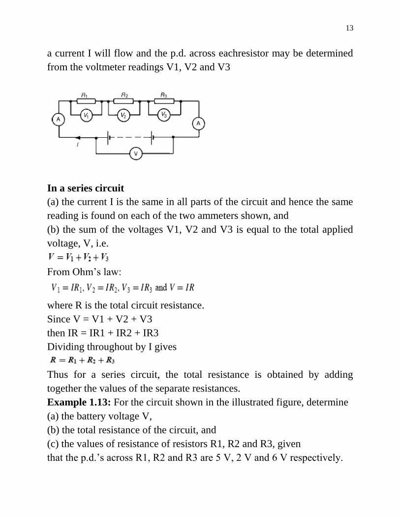
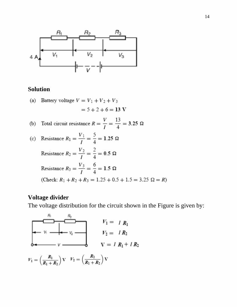
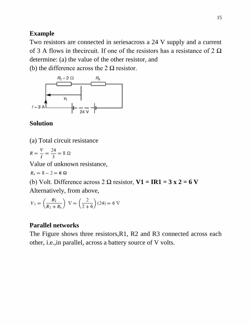
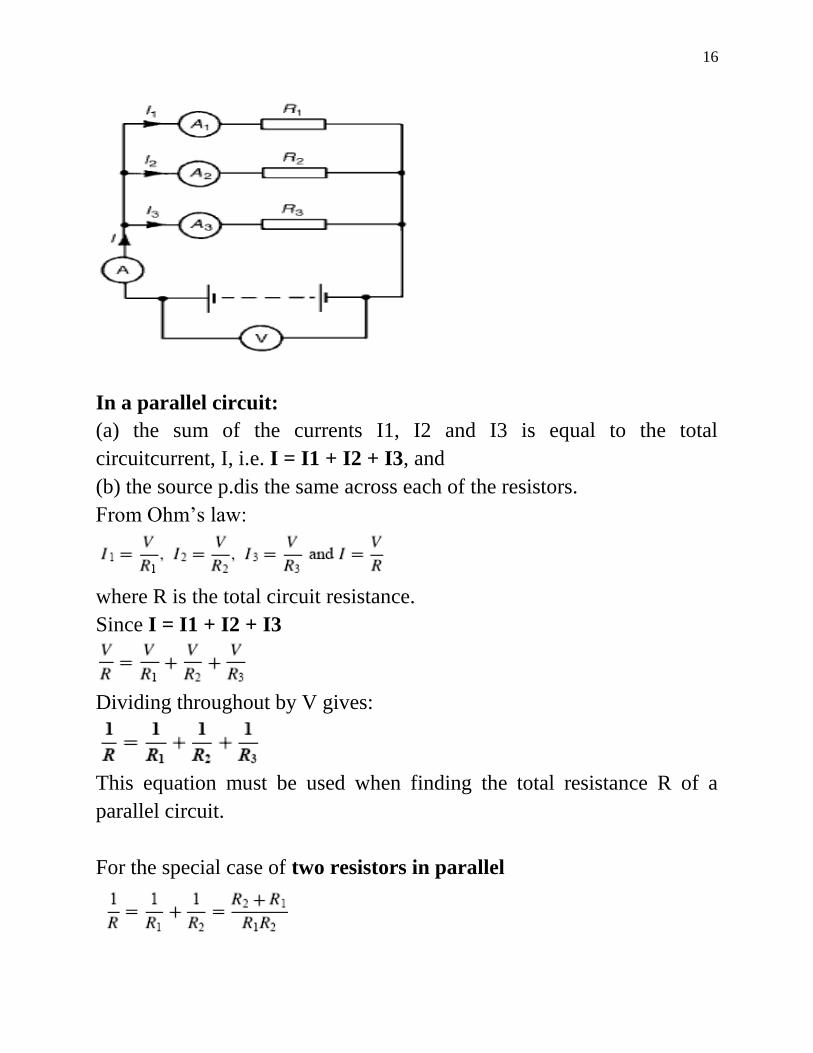
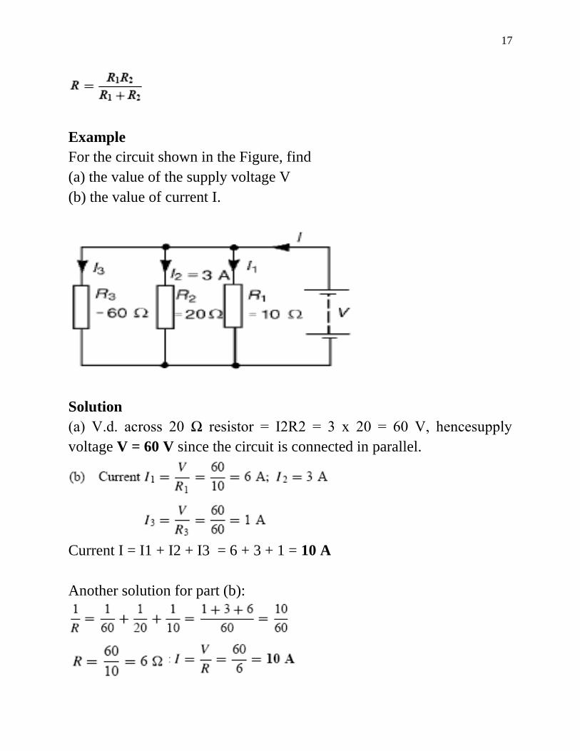
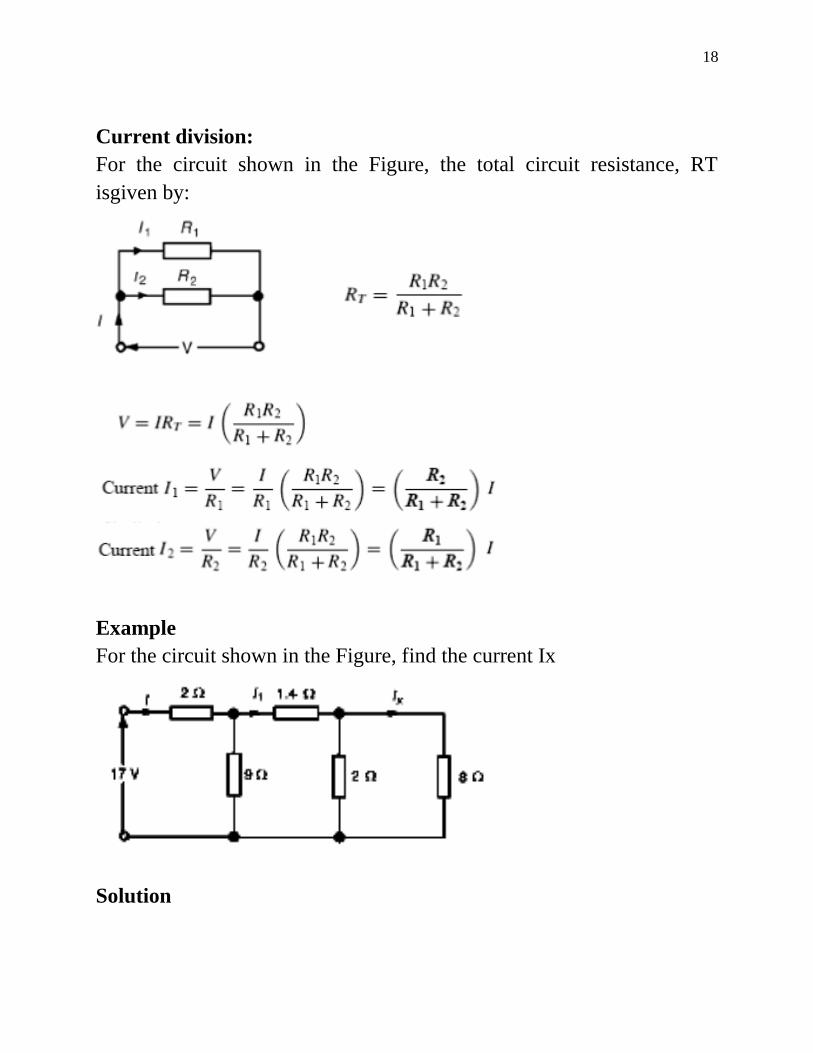
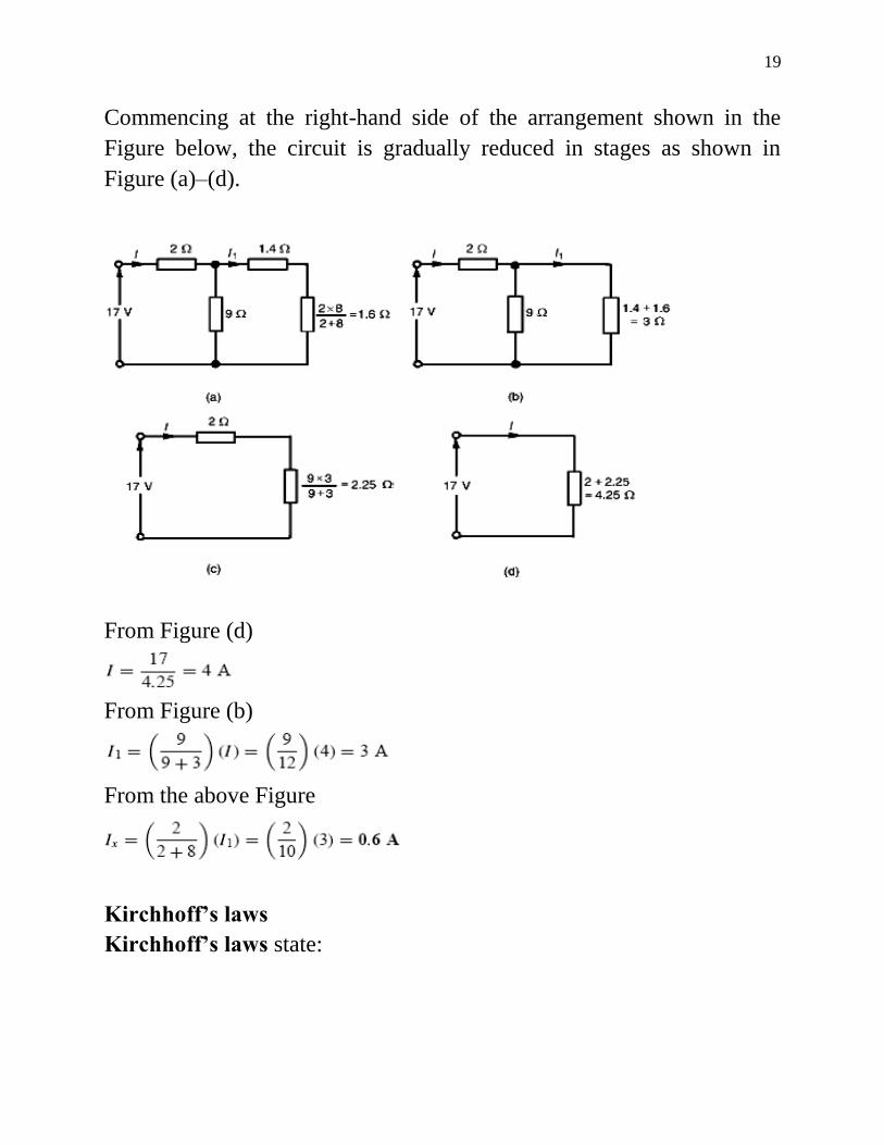
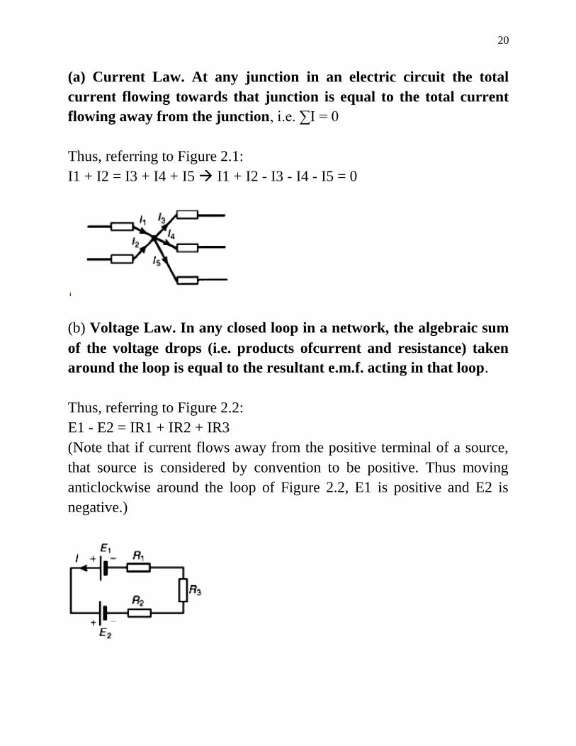
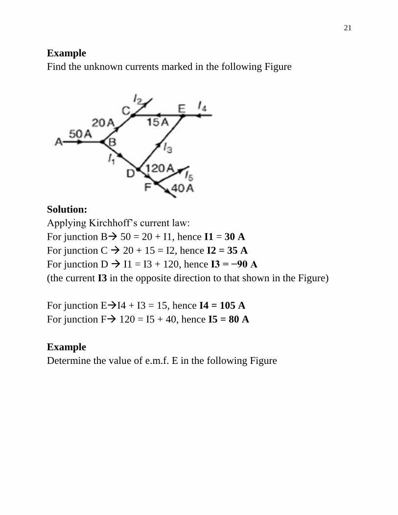
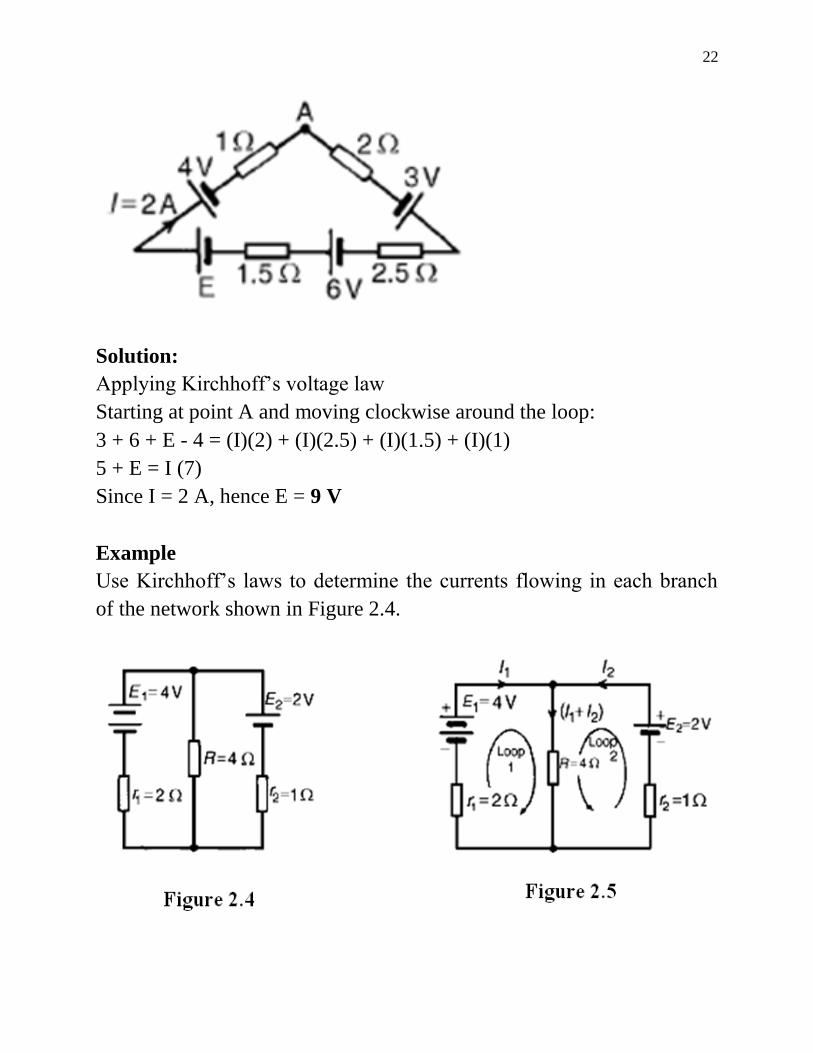
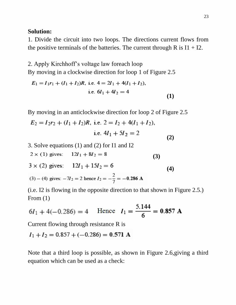
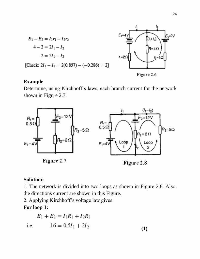
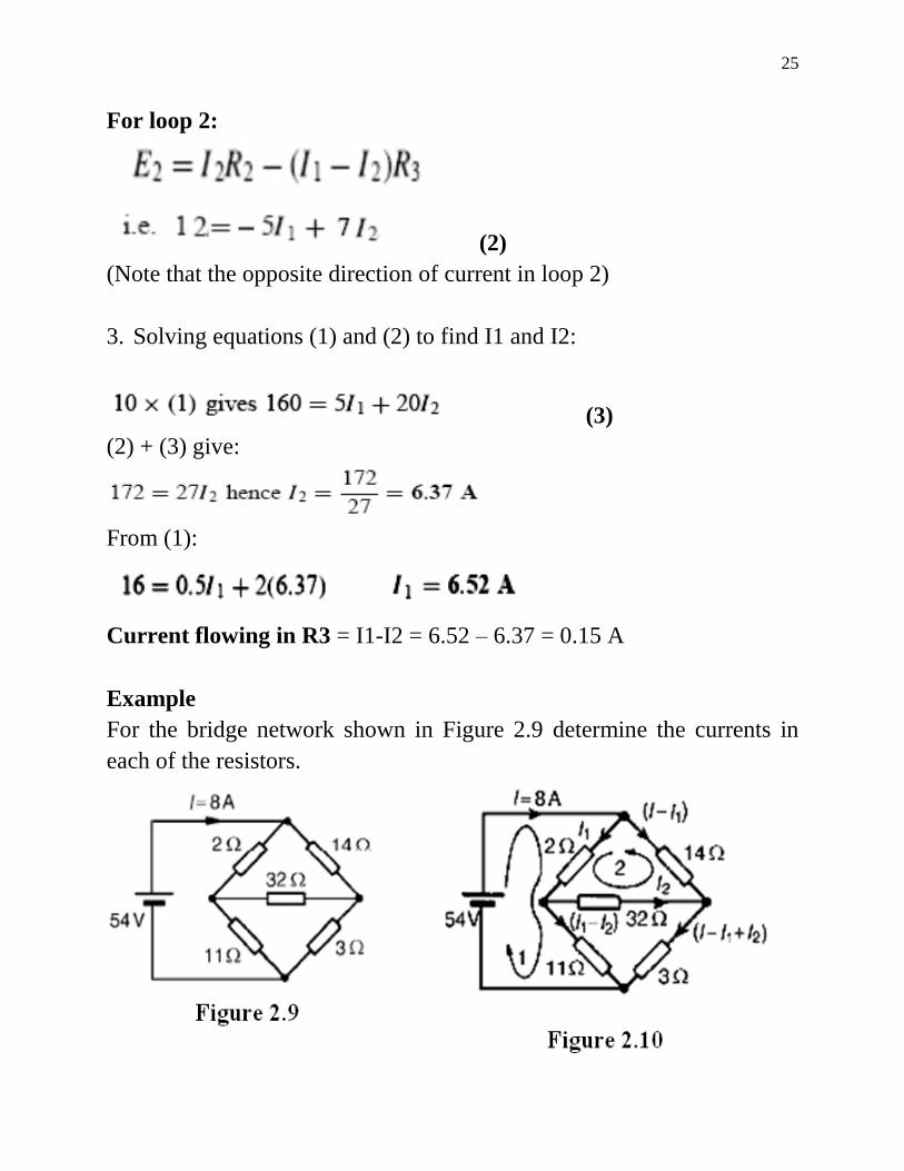
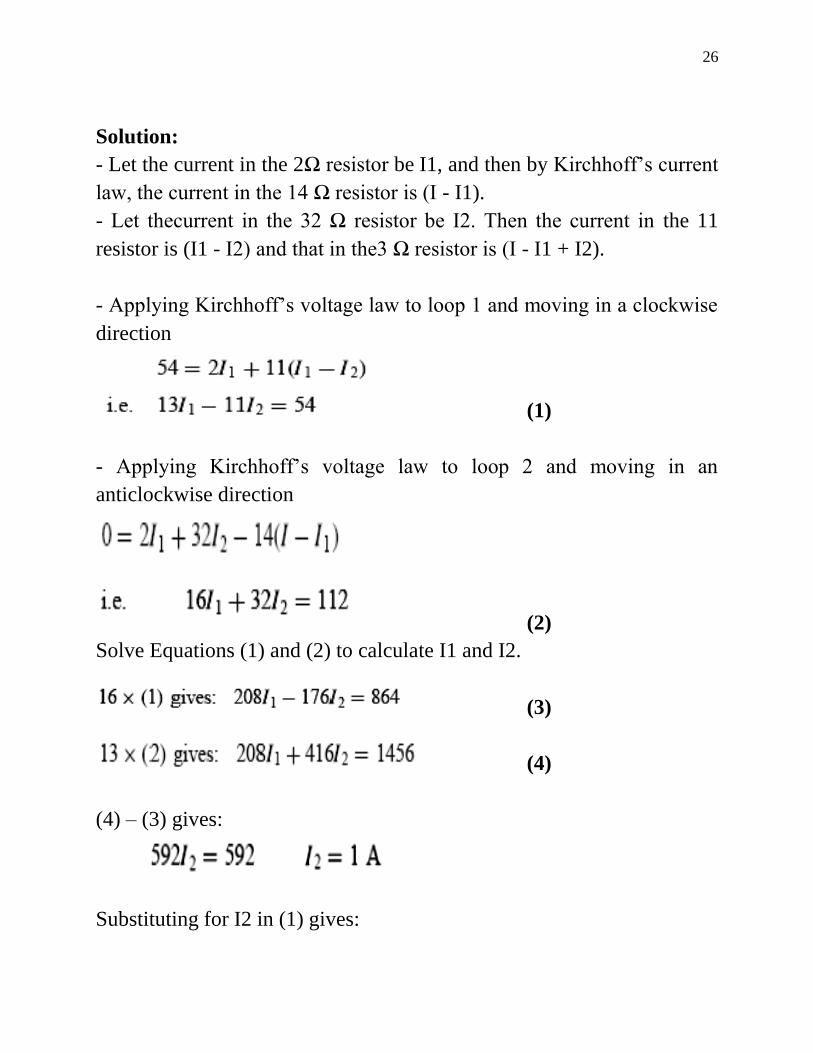
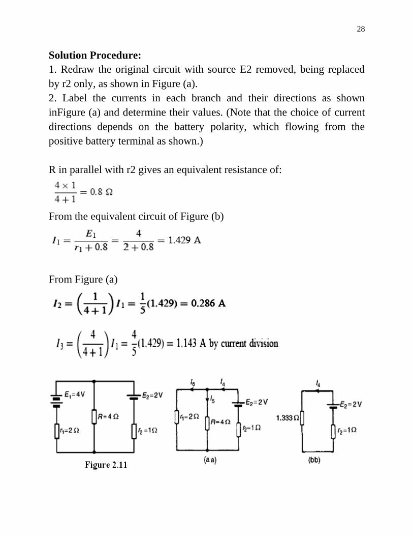
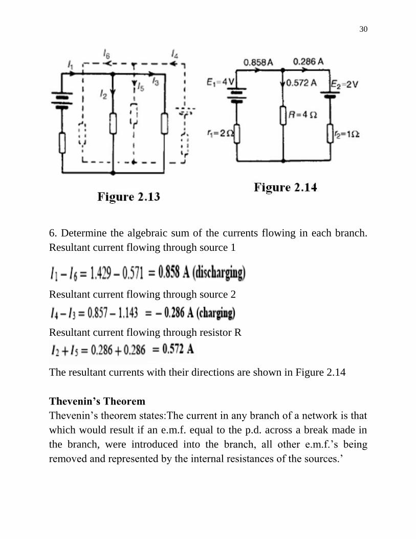
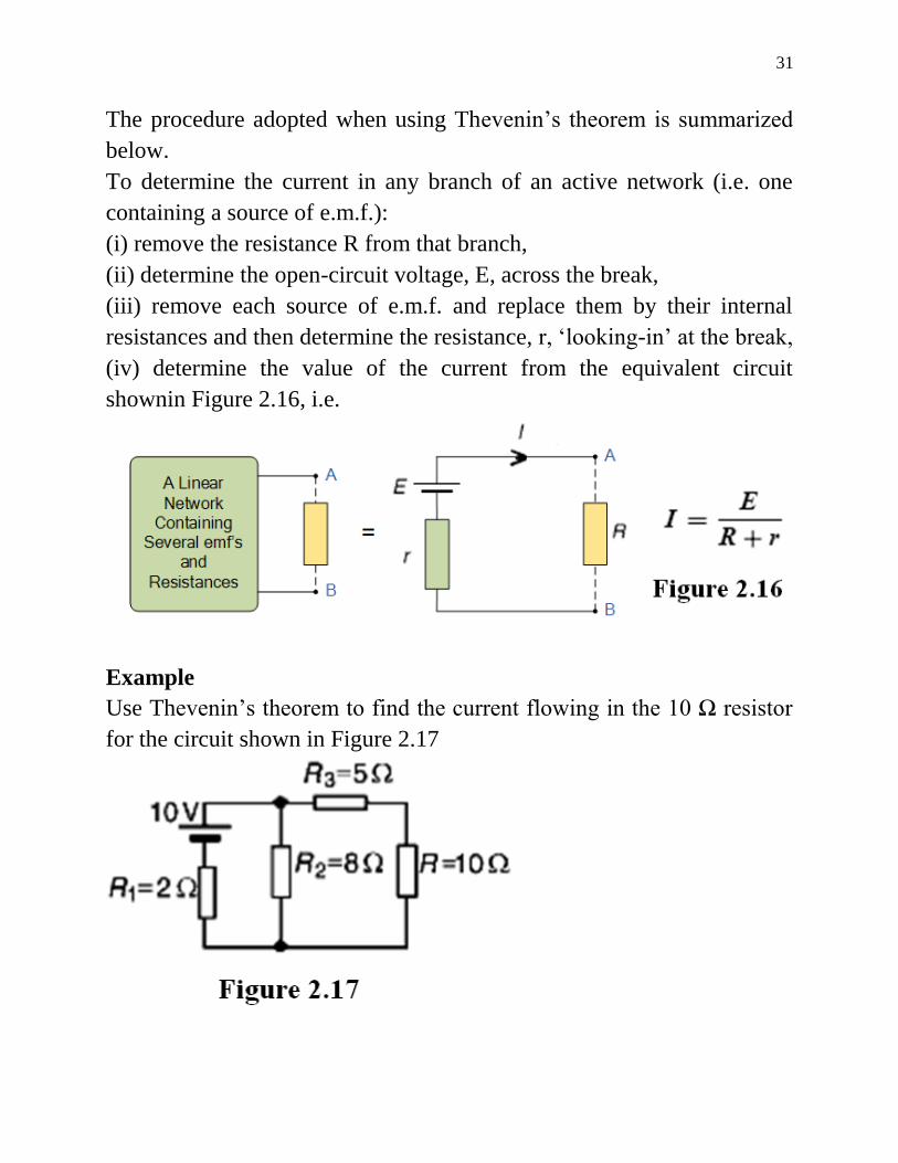
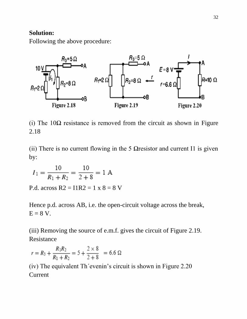
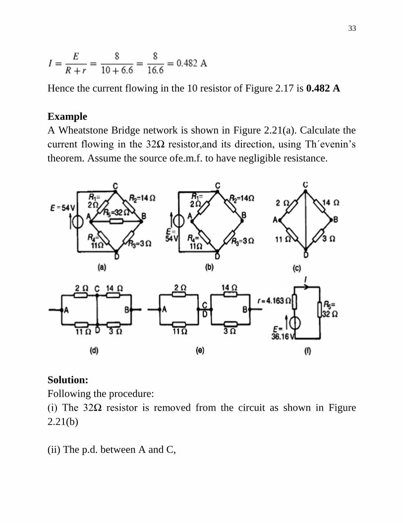
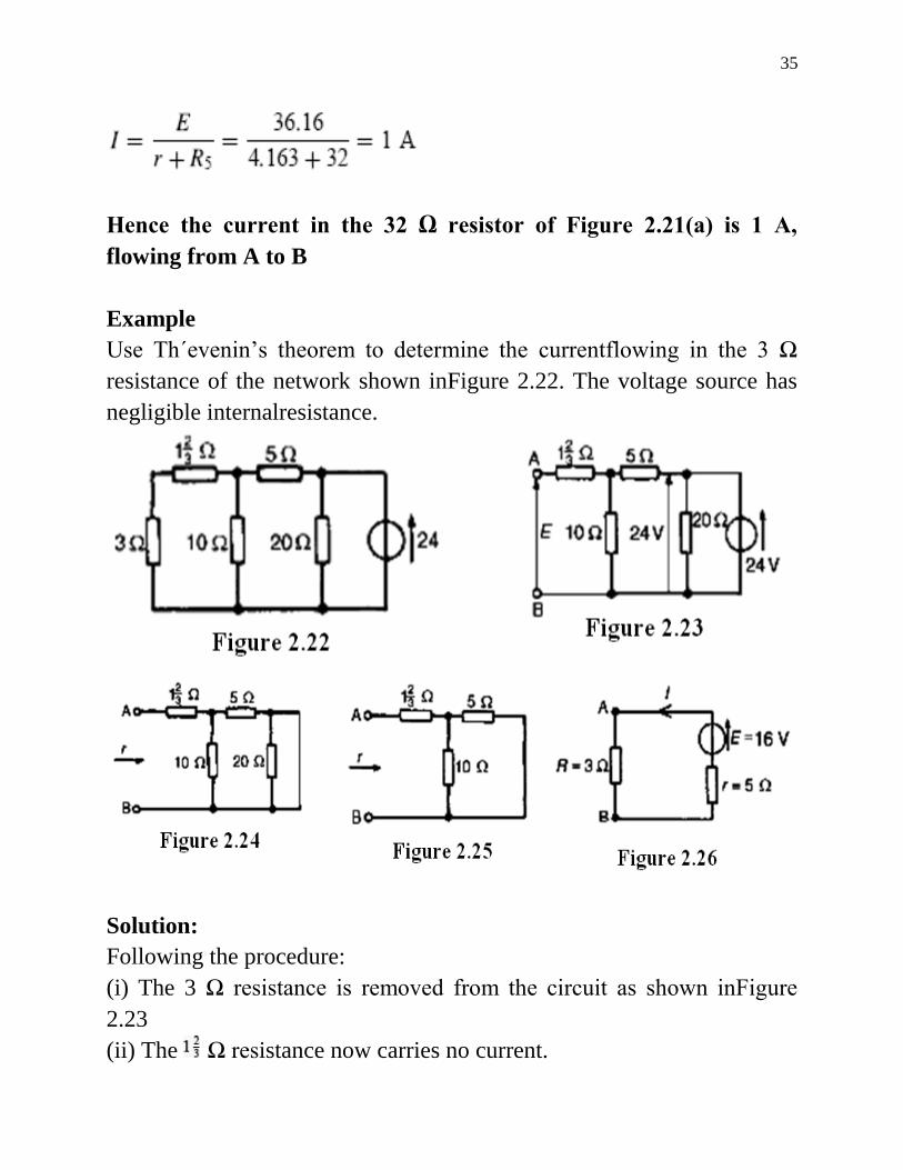
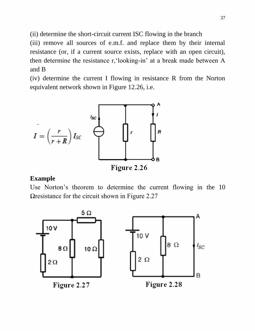
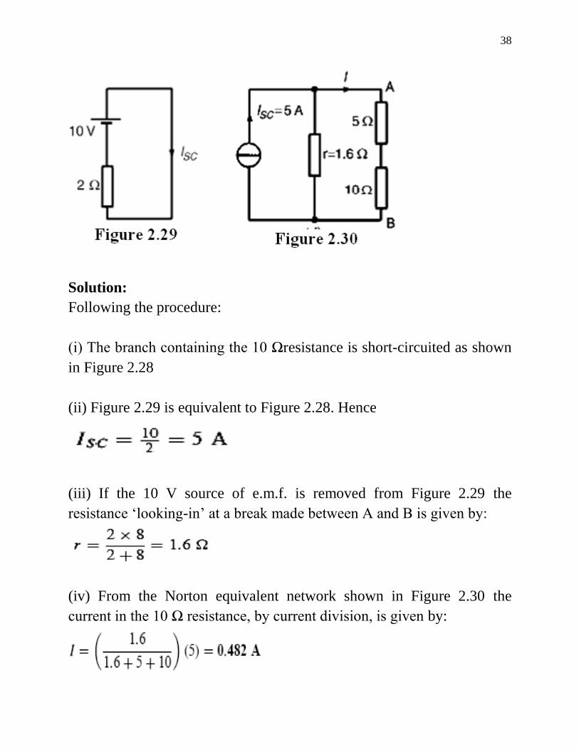
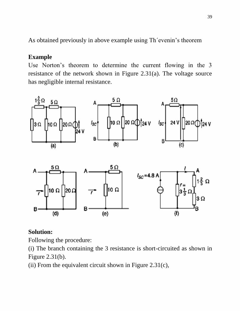
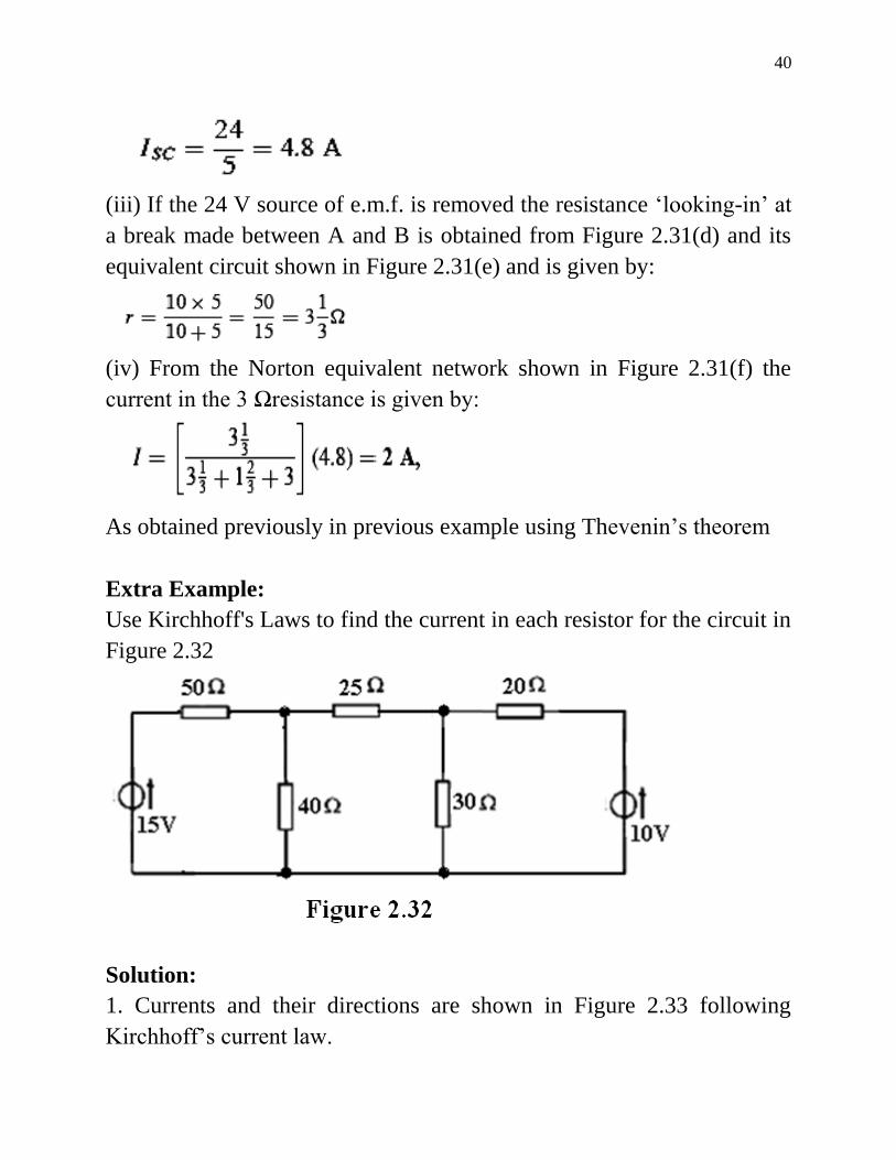
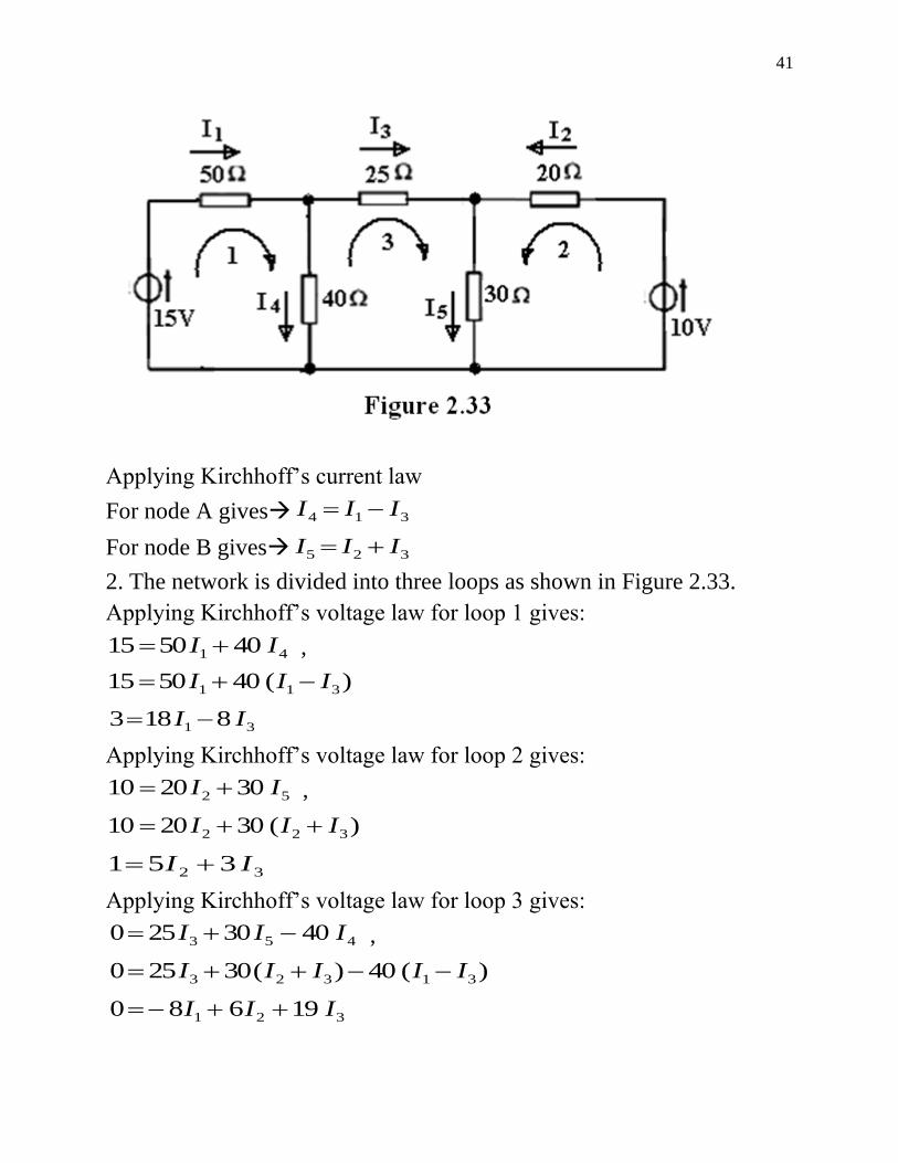
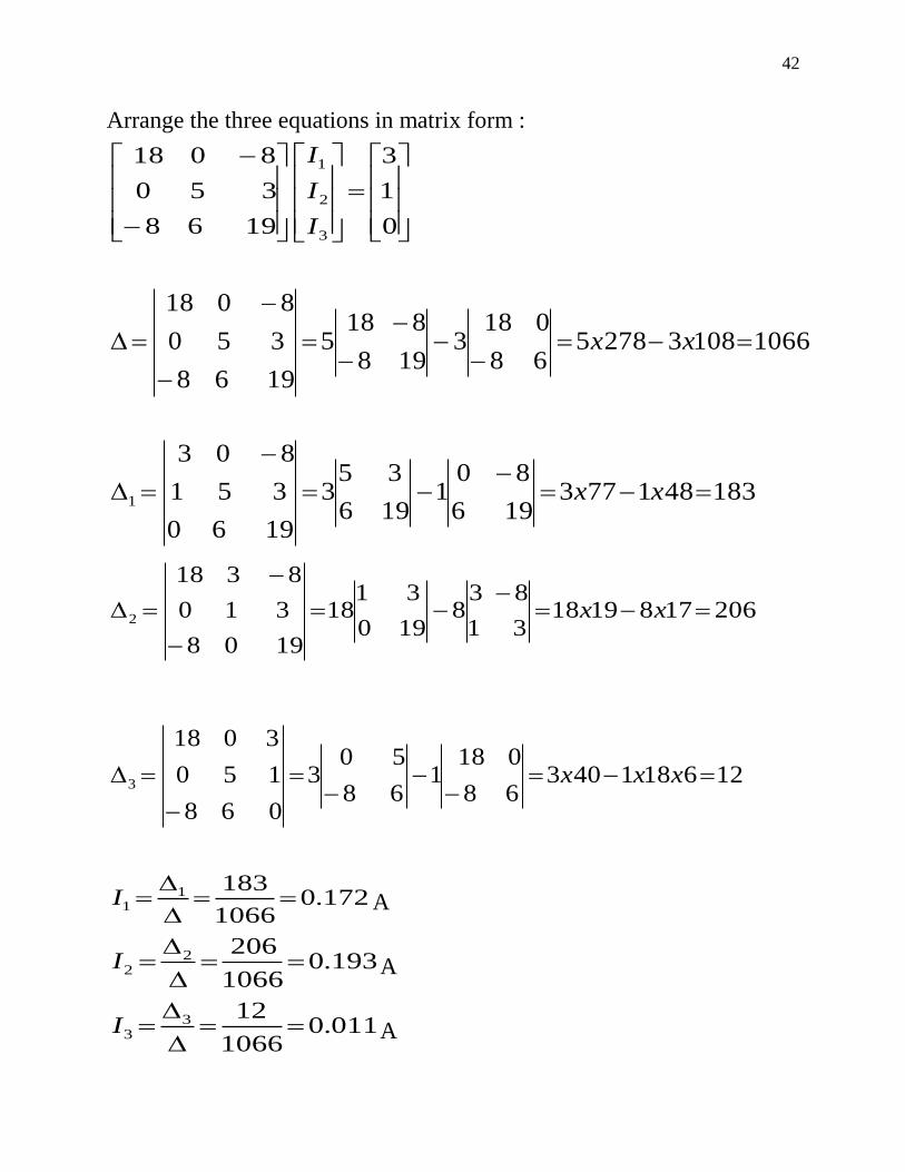
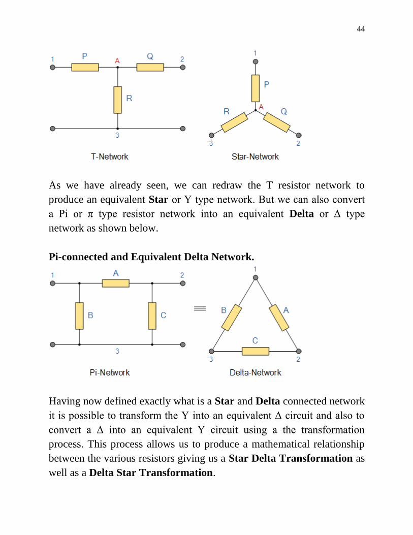
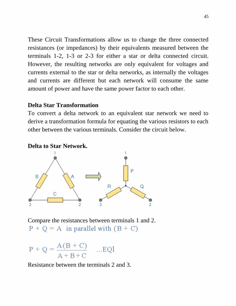
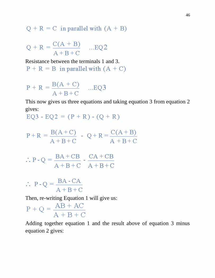
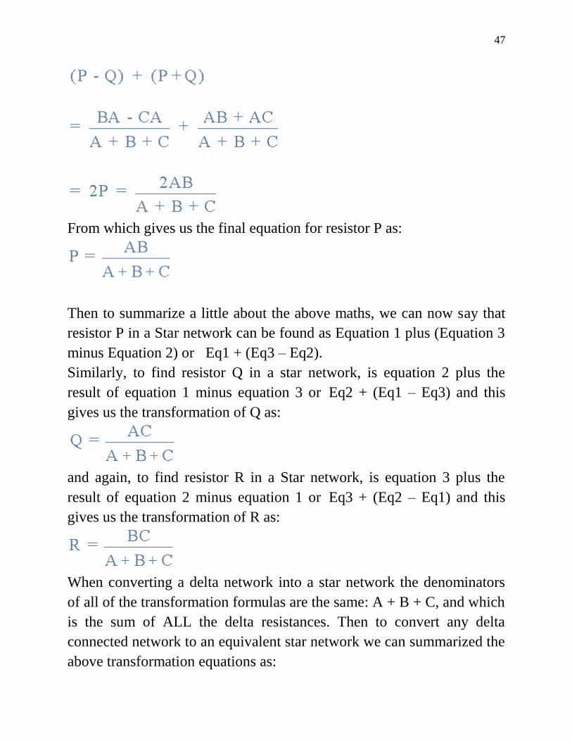
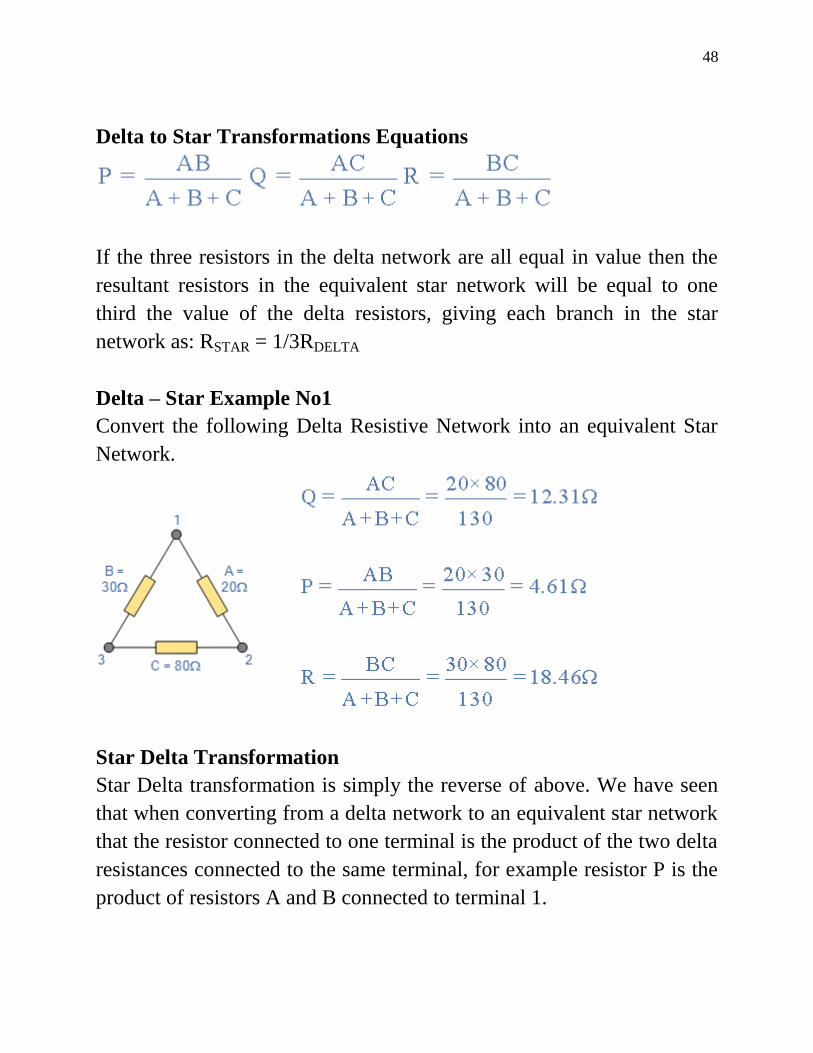
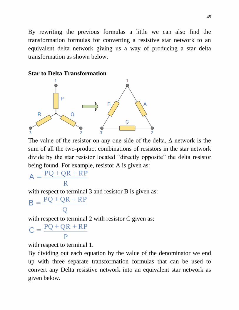
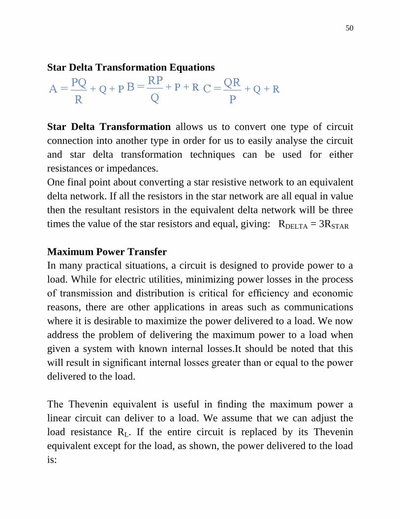
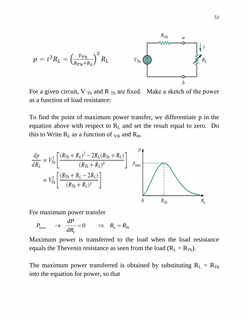
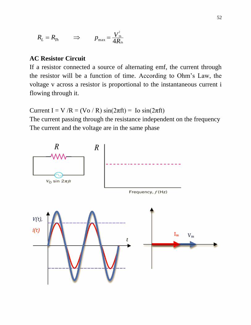
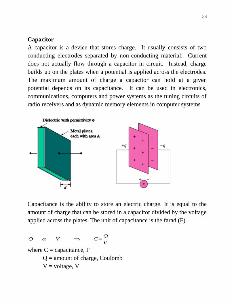
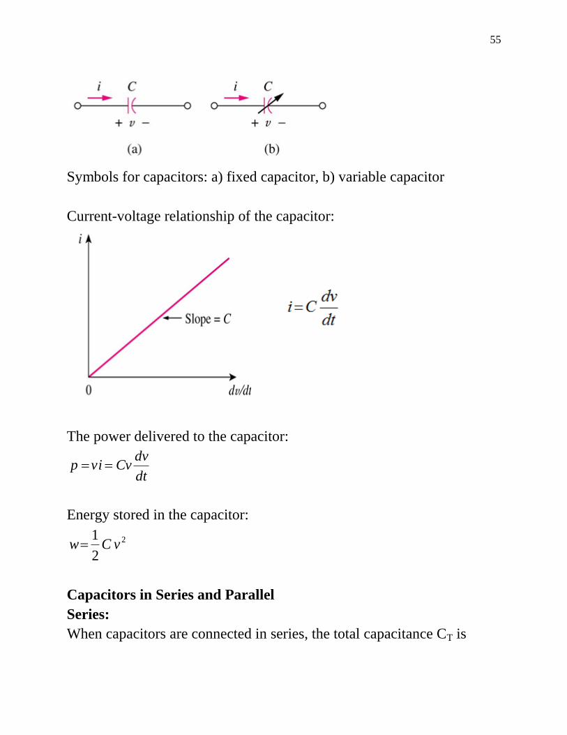
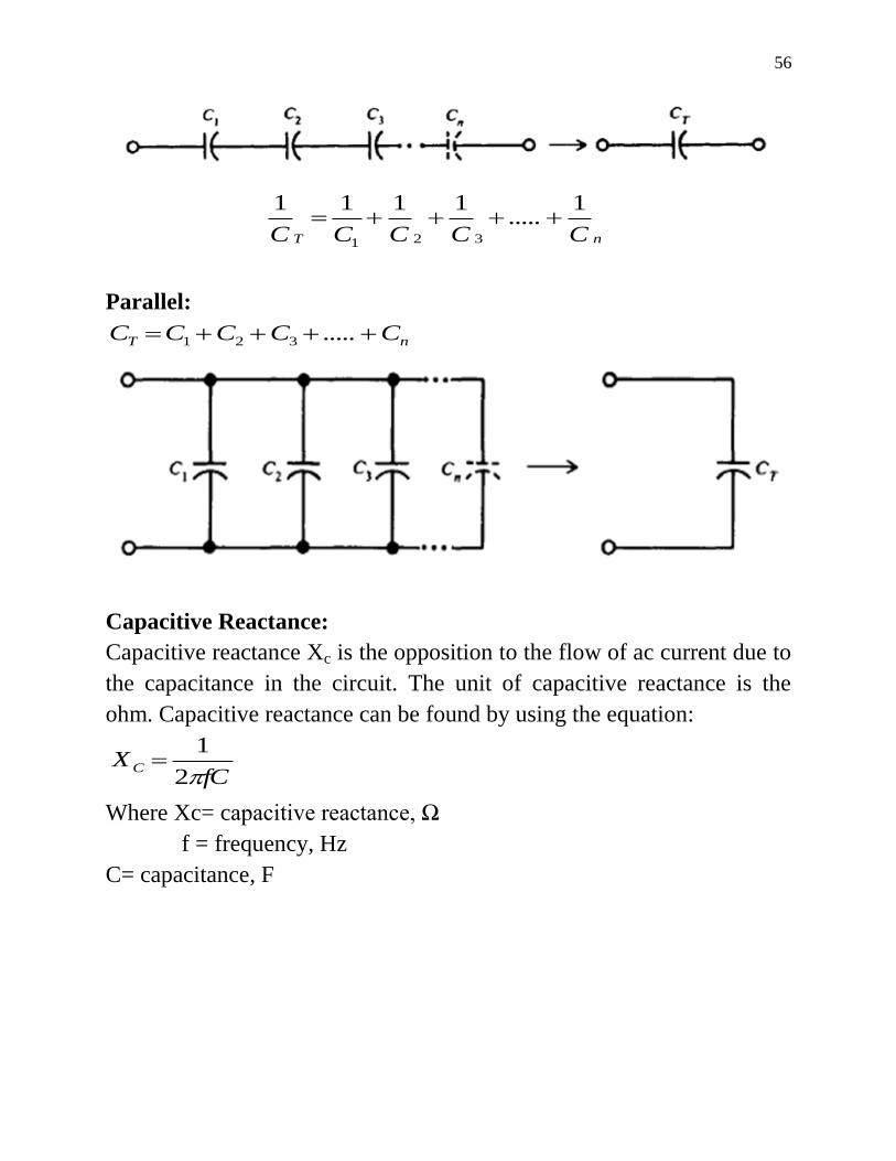
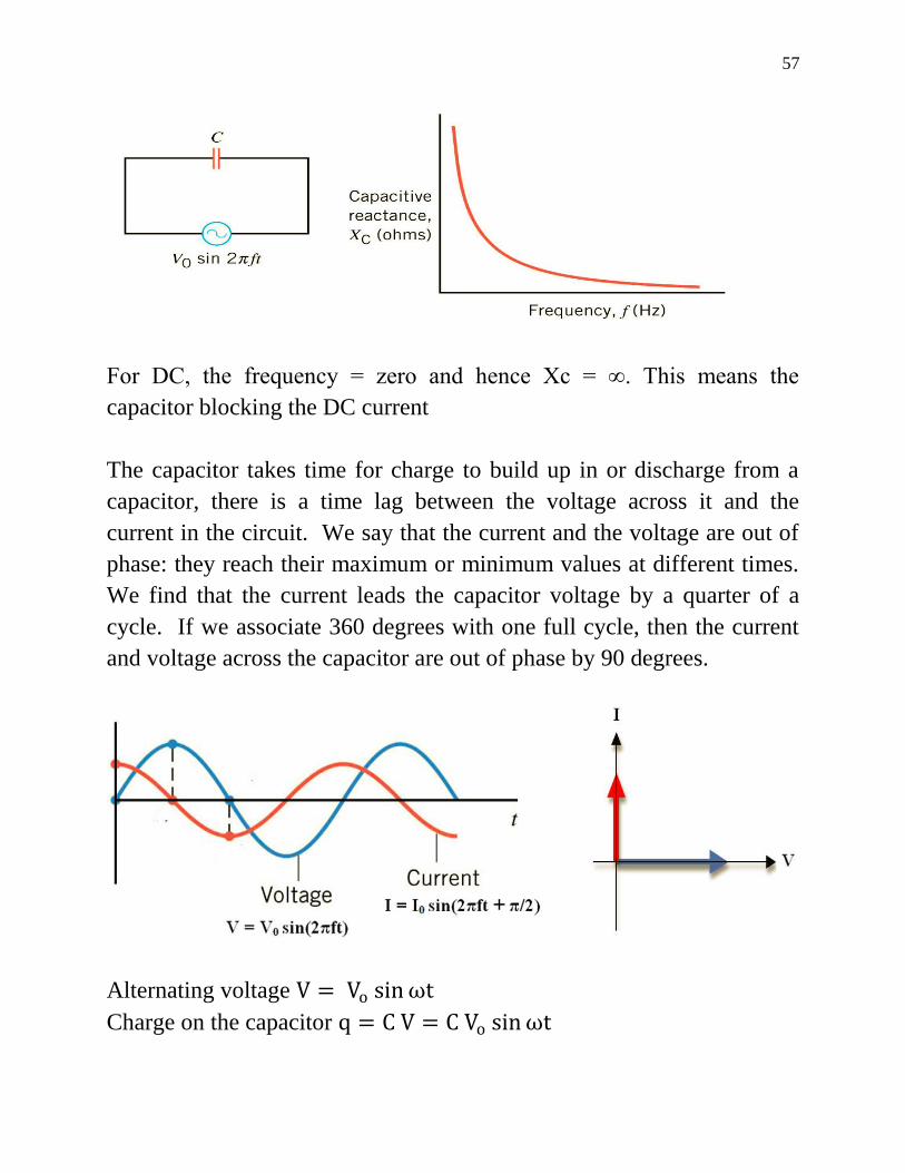
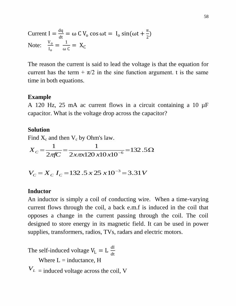
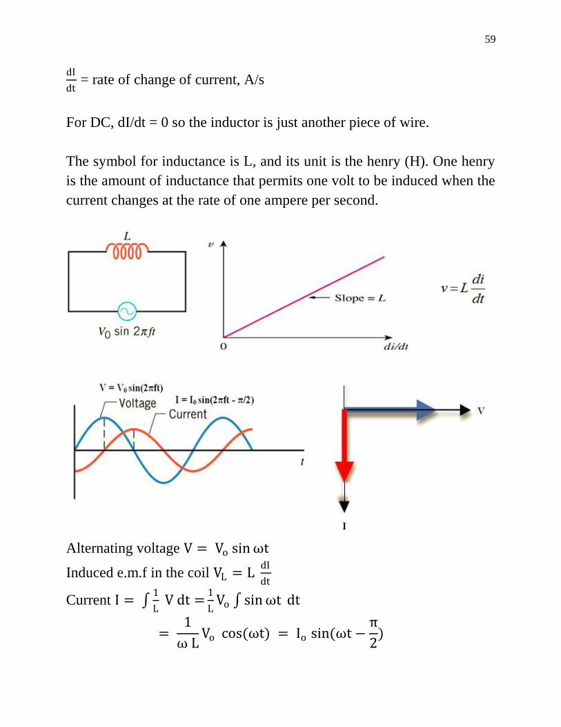
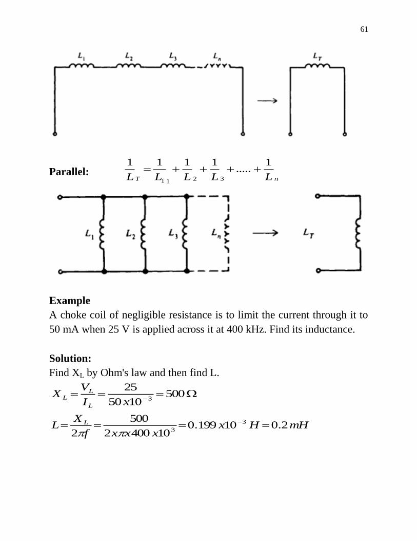
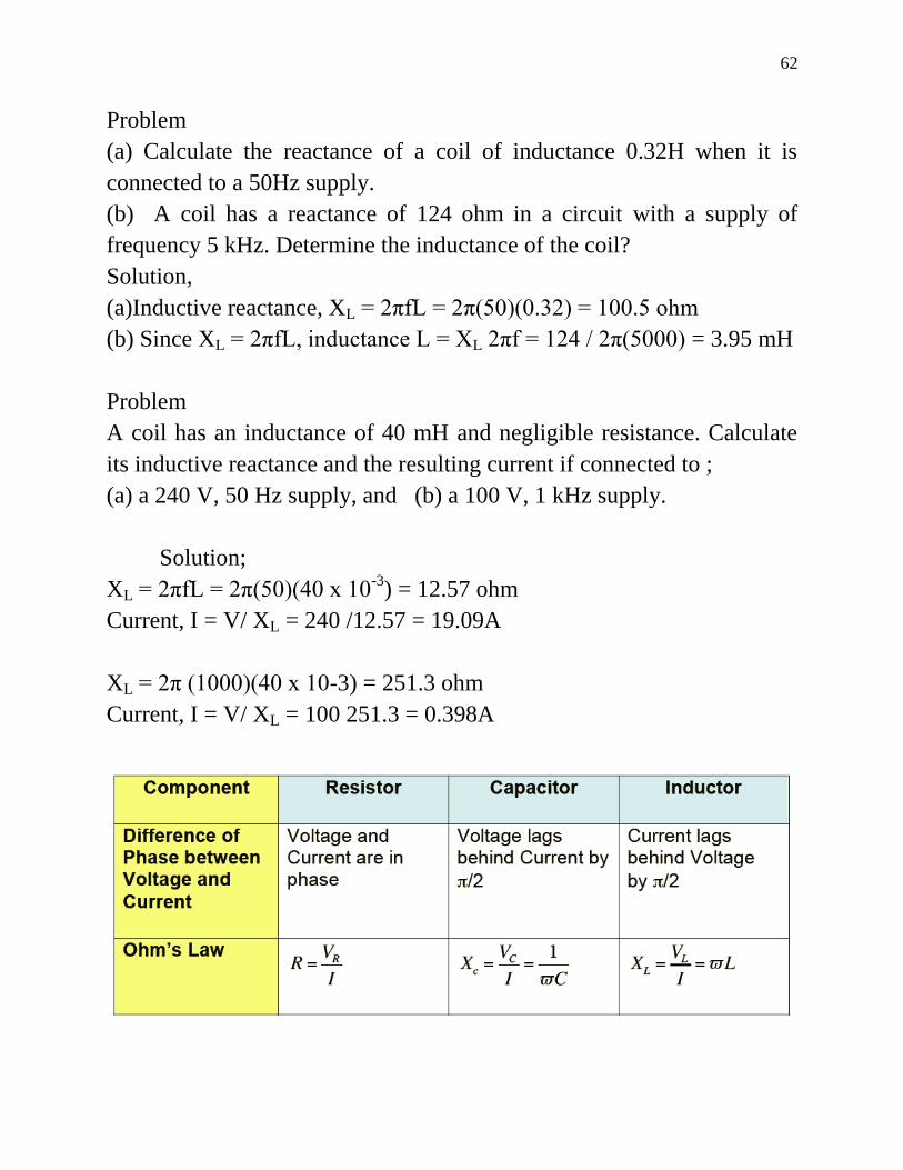
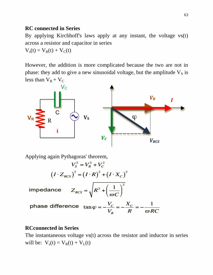
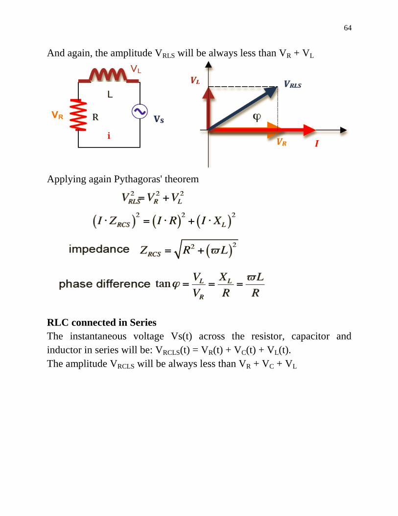
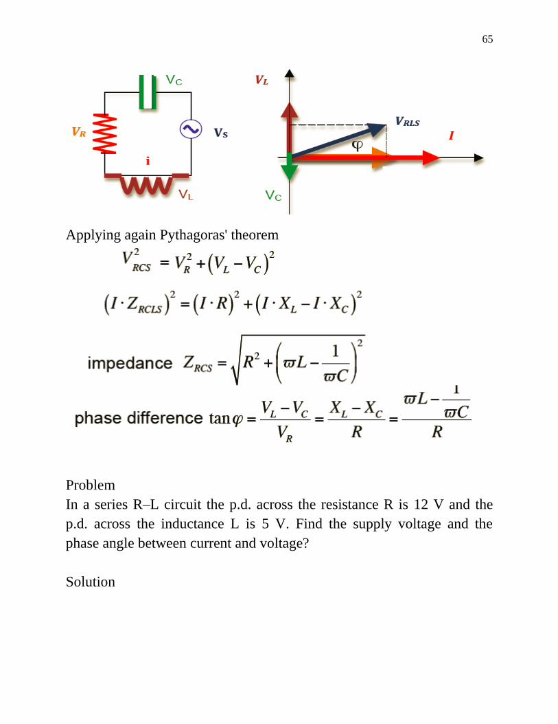
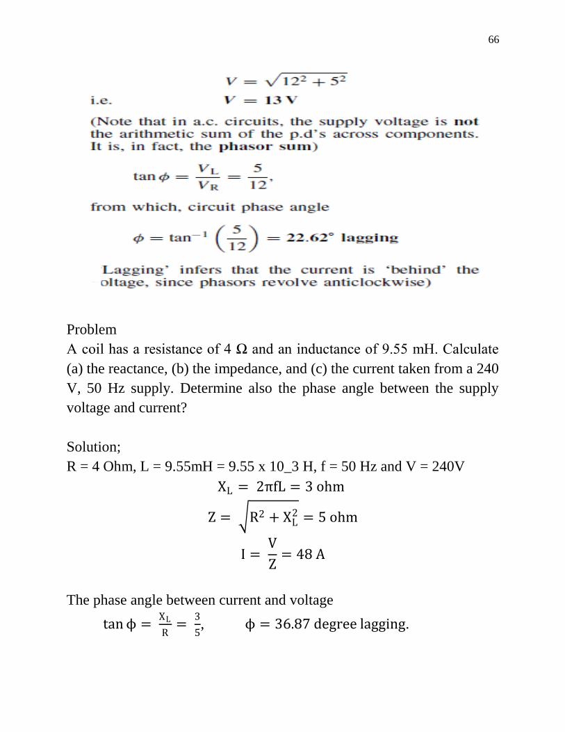
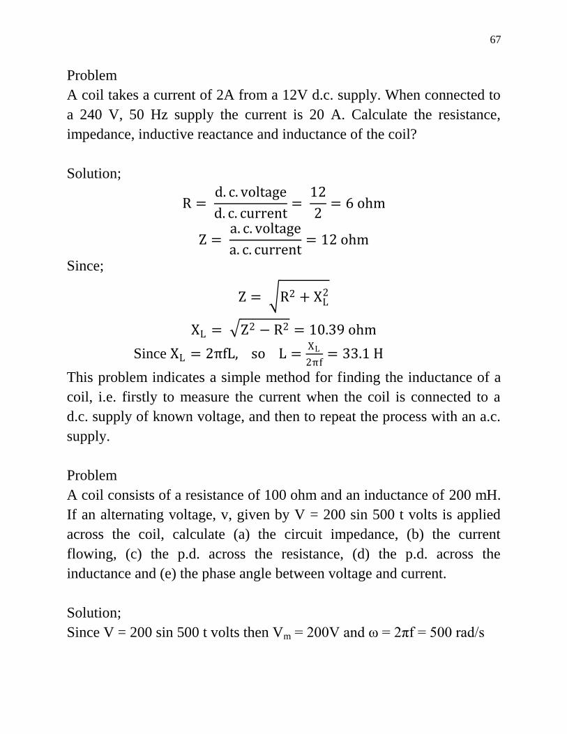
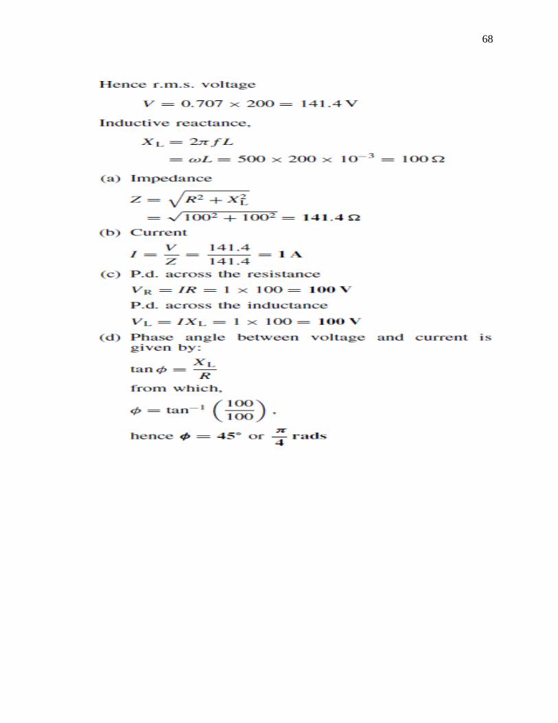
68


![[MEAN WELL] 1982 (Charger) DC/AC (Inverter) 8000 (DoE ... · PDF fileAC/DC DC/DC (Converter) (Adaptor) (Charger) DC/AC (Inverter) 8000 LED ... AC AC AC GE12/18/24/30 I AC AC Plug-AU](https://static.documents.pub/doc/80x56/5a73363b7f8b9abb538e72a6/mean-well-1982-charger-dcac-inverter-8000-doe-a-acdc-dcdc-converter.jpg)


