This paper was presented at the Fourteenth Meeting “New Trends in Fatigue and Fracture” (NT2F14) Belgrade, Serbia, 15–18 September, 2014 Gordana Bakić 1 , Vera Šijački Žeravčić 1 , Miloš Djukić 1 , Bratislav Rajičić 1 , Miladin Radović 2 , Ivan Gajić 3 , Aleksandar Maslarević 4 , Aleksandar Jakovljević 5 CHARACTERISATION OF UNDERMATCH WELDED JOINT OF X20CRMOV121 STEEL AFTER PROLONGED SERVICE KARAKTERIZACIJA RAZNORODNOG ZAVARENOG SPOJA IZRAĐENOG OD X20CrMoV121 ČELIKA POSLE PRODUŽENE EKSPLOATACIJE Originalni naučni rad / Original scientific paper UDK /UDC: 621.791:669.15-194.55 Rad primljen / Paper received: 24.09.2014 Adresa autora / Author's address: 1) University of Belgrade, Faculty of Mechanical Engineer- ing, Serbia, [email protected]2) Department of Mechanical Engineering, Texas A&M, College Station, TX, U.S.A. 3) TPP “Nikola Tesla B”, Ušće, Obrenovac, Serbia 4) University of Belgrade, Faculty of Mechanical Engineer- ing – Innovation Centre, Serbia 5) Electric Power Industry of Serbia, Belgrade, Serbia Keywords • heat resistant martensitic steel • repair welding Abstract Heat resistant martensitic steel X20CrMoV121 (DIN) is extensively used in the last few decades as a material for tubing systems and pipelines in thermal power plants. Long term behaviour of this material is well known and understood. X20CrMoV121 is found to be reliable for prolonged service at elevated temperatures. Main disadvantage is poor weld- ability, apart from other properties of great importance for tubing systems. Failure of the tubing system during service requires quick replacement of damaged parts. In situ repair welding of martensitic steels is always problematic since it requires special welding techniques usually difficult to perform in short time during forced outages. Here we report on the repair welding procedure for the outlet superheater in two 600 MW lignite power plant units. The super heater is made of X20CrMoV121 (DIN). Outlet temperature and pressure in the super heater system are 540°C and 18.6 MPa. The local thinning of tube walls is found to be the main damage mechanism of the super heater during prolonged service. Highly erosive lignite combustion particles are identified as the main reason for wall thinning. A serious problem is the long required period for repair welding of damaged martensitic X20CrMoV121 steel. The solution was cold welding involving repair welding by austenitic electrode with high nickel and chromium content. This technique has many advantages as short welding time, no need for special atmosphere and preheating treatment, relatively easy welding process, etc. Repaired joints are usually replaced during next overhaul, but for investigation purposes some are maintained in service over 10 years. Intensive characterization of base and filler material of repair welds after 10 years service is reported in this paper. Ključne reči • toplotno postojan martenzitni čelik • reparaturno zavarivanje Izvod Toplotno postojani martenzitni čelik X20CrMoV121 (DIN) se intenzivno koristi poslednjih nekoliko decenija za cevni sistem i cevovode u termoelektranama. Dugoročno ponaša- nje ovog materijala u eksploataciji je vrlo dobro poznato i priznato. X20CrMoV121 se pokazao kao pouzdan u dugoroč- nom periodu rada na povišenim temperaturama. Glavni nedostatak je slaba zavarljivost koja je uz ostala svojstva od velikog značaja za cevni sistem. Lomovi na cevnom sistemu u eksploataciji zahtevaju brzu zamenu oštećenih delova. Repa- raturno zavarivanje na licu mesta martenzitnih čelika je uvek problematično jer zahteva posebne tehnike zavarivanja, koje je obično teško izvršiti za kratko vreme tokom prinudnog prekida. Opisan je postupak reparaturnog zavarivanja za poprav- ku izlaznog pregrejača na dva bloka po 600 MW termoelektrane na lignit. Pregrejač je od X20 CrMoV121 (DIN). Temperatura i pritisak pare na izlazu iz pregrejača su 540°C i 18,6 MPa. Lokalno stanjenje zidova cevi je detektovano kao glavni meha- nizam oštećenja pregrejača tokom njegovog produženog veka. Visoki sadržaj abrazivnih čestica produkata sagorevanja lig- nita je identifikovan kao glavni razlog stanjenja zidova cevi. Dug period reparaturnog zavarivanja oštećenog X20Cr MoV121 čelika je ozbiljan problem. Rešenje je u tzv. ’hladnom zavarivanju’ sa reparaturnim zavarivanjem austenitnom elek- trodom visokog sadržaja nikla i hroma. Ova tehnika ima pred- nosti: kratko vreme zavarivanja, odsustvo posebne atmosfere i predgrevanja, relativno lak proces zavarivanja, itd. Repari- rani spojevi su obično zamenjeni tokom narednog remonta, ali u cilju istrage neki su održavani u eksploataciji i više od 10 godina. Rezime intenzivne karakterizacije osnovnog i dodatnog materijala repariranih zavarenih spojeva, posle 10 godina rada, je opisan u ovom radu. INTEGRITET I VEK KONSTRUKCIJA Vol. 14, br. 2 (2014), str. 133–140 STRUCTURAL INTEGRITY AND LIFE Vol. 14, No 2 (2014), pp. 133–140 133
Transcript
This paper was presented at the Fourteenth Meeting “New Trends in Fatigue and Fracture” (NT2F14)
Belgrade, Serbia, 15–18 September, 2014
Gordana Bakić1, Vera Šijački Žeravčić1, Miloš Djukić1, Bratislav Rajičić1, Miladin Radović2, Ivan Gajić3, Aleksandar Maslarević4, Aleksandar Jakovljević5
CHARACTERISATION OF UNDERMATCH WELDED JOINT OF X20CRMOV121 STEEL AFTER PROLONGED SERVICE
KARAKTERIZACIJA RAZNORODNOG ZAVARENOG SPOJA IZRAĐENOG OD X20CrMoV121 ČELIKA POSLE PRODUŽENE EKSPLOATACIJE
Originalni naučni rad / Original scientific paper UDK /UDC: 621.791:669.15-194.55 Rad primljen / Paper received: 24.09.2014
Adresa autora / Author's address: 1) University of Belgrade, Faculty of Mechanical Engineer-ing, Serbia, [email protected] 2) Department of Mechanical Engineering, Texas A&M, College Station, TX, U.S.A. 3) TPP “Nikola Tesla B”, Ušće, Obrenovac, Serbia 4) University of Belgrade, Faculty of Mechanical Engineer-ing – Innovation Centre, Serbia 5) Electric Power Industry of Serbia, Belgrade, Serbia
Heat resistant martensitic steel X20CrMoV121 (DIN) is extensively used in the last few decades as a material for tubing systems and pipelines in thermal power plants. Long term behaviour of this material is well known and understood. X20CrMoV121 is found to be reliable for prolonged service at elevated temperatures. Main disadvantage is poor weld-ability, apart from other properties of great importance for tubing systems. Failure of the tubing system during service requires quick replacement of damaged parts. In situ repair welding of martensitic steels is always problematic since it requires special welding techniques usually difficult to perform in short time during forced outages. Here we report on the repair welding procedure for the outlet superheater in two 600 MW lignite power plant units. The super heater is made of X20CrMoV121 (DIN). Outlet temperature and pressure in the super heater system are 540°C and 18.6 MPa. The local thinning of tube walls is found to be the main damage mechanism of the super heater during prolonged service. Highly erosive lignite combustion particles are identified as the main reason for wall thinning.
A serious problem is the long required period for repair welding of damaged martensitic X20CrMoV121 steel. The solution was cold welding involving repair welding by austenitic electrode with high nickel and chromium content. This technique has many advantages as short welding time, no need for special atmosphere and preheating treatment, relatively easy welding process, etc. Repaired joints are usually replaced during next overhaul, but for investigation purposes some are maintained in service over 10 years. Intensive characterization of base and filler material of repair welds after 10 years service is reported in this paper.
Ključne reči • toplotno postojan martenzitni čelik • reparaturno zavarivanje
Izvod
Toplotno postojani martenzitni čelik X20CrMoV121 (DIN) se intenzivno koristi poslednjih nekoliko decenija za cevni sistem i cevovode u termoelektranama. Dugoročno ponaša-nje ovog materijala u eksploataciji je vrlo dobro poznato i priznato. X20CrMoV121 se pokazao kao pouzdan u dugoroč-nom periodu rada na povišenim temperaturama. Glavni nedostatak je slaba zavarljivost koja je uz ostala svojstva od velikog značaja za cevni sistem. Lomovi na cevnom sistemu u eksploataciji zahtevaju brzu zamenu oštećenih delova. Repa-raturno zavarivanje na licu mesta martenzitnih čelika je uvek problematično jer zahteva posebne tehnike zavarivanja, koje je obično teško izvršiti za kratko vreme tokom prinudnog prekida. Opisan je postupak reparaturnog zavarivanja za poprav-ku izlaznog pregrejača na dva bloka po 600 MW termoelektrane na lignit. Pregrejač je od X20 CrMoV121 (DIN). Temperatura i pritisak pare na izlazu iz pregrejača su 540°C i 18,6 MPa. Lokalno stanjenje zidova cevi je detektovano kao glavni meha-nizam oštećenja pregrejača tokom njegovog produženog veka. Visoki sadržaj abrazivnih čestica produkata sagorevanja lig-nita je identifikovan kao glavni razlog stanjenja zidova cevi.
Dug period reparaturnog zavarivanja oštećenog X20Cr MoV121 čelika je ozbiljan problem. Rešenje je u tzv. ’hladnom zavarivanju’ sa reparaturnim zavarivanjem austenitnom elek-trodom visokog sadržaja nikla i hroma. Ova tehnika ima pred-nosti: kratko vreme zavarivanja, odsustvo posebne atmosfere i predgrevanja, relativno lak proces zavarivanja, itd. Repari-rani spojevi su obično zamenjeni tokom narednog remonta, ali u cilju istrage neki su održavani u eksploataciji i više od 10 godina. Rezime intenzivne karakterizacije osnovnog i dodatnog materijala repariranih zavarenih spojeva, posle 10 godina rada, je opisan u ovom radu.
INTEGRITET I VEK KONSTRUKCIJA Vol. 14, br. 2 (2014), str. 133–140
STRUCTURAL INTEGRITY AND LIFEVol. 14, No 2 (2014), pp. 133–140
Characterisation of undermatch welded joint of X20CrMoV121 … Karakterizacija raznorodnog zavarenog spoja izrađenog od …
INTRODUCTION
The main purpose of repair welding during power plant maintenance is to restore quickly the serviceability of the original part which failed incidentally during service, /1/. Since repair welding can be performed at minimal costs and short times during the outages /2/, it has been a widely used procedure to repair accidental damages of the tubing system which are considered to be the most frequent causes of boiler outage.
Tubes of low-carbon and low-alloy steels can be welded during outages without adversely affecting the service life. On the other hand, the tubes made of martensitic steels such as X20CrMoV121 (according to DIN) with relatively high-carbon content, and poor weldаbility have to be properly heat treated to provide adequate quality and service life of welded joints, /3/. In general, martensitic heat resistant steels harden during heat treatment. However, low-carbon martensitic steels can still be welded without special pre-cautions. If the content of carbon exceeds 0.15% as in the case of X20CrMoV121 with carbon content of approxi-mately 0.2%, the heat treatment before and after welding is required to avoid hardening of the material as well as very slow cooling after the post-welding heat treatment.
However, the application of pre- and post-welding heat treatment with slow cooling is not always an acceptable solution, especially during very short outages. In that case, the austenitic stainless steel filler metal could be used to repair the tubes made of martensitic steels. If operational temperatures do not exceed 300°C, nickel-based alloys that contain 70% Ni and 20% Cr (70/20 alloy) are usually used as a filler material, /1/, but they are used also beyond that temperature. So called ‘cold repair welding’ of martensitic steels using austenitic filler material has many advantages over the regular procedure. The most important are: short welding time, no need for special atmosphere and preheat-ing treatment, relatively easy welding process, etc. How-ever, cold repair welding is mostly considered to be only a temporarily solution for damage repair and most of those welds are replaced during the next overhaul. However, in order to study the long-term behaviour of cold repair welds, we have kept some of those welds in service for more than 10 years.
The microstructure and mechanical properties of some welds are characterized after the long term exposure to service conditions and the results are reported in this paper.
EXPERIMENTAL DETAILS
The outlet superheater (SH) tube system of a 600 MW fossil fuel power plant boiler is made of X20CrMoV121 steel (DIN-17175/79). The SH consists of 38 mm tubes with the different wall thicknesses in different sections, Table 1. The inlet part of SH is made of tubes with wall thickness of 4 or 4.5 mm because inlet operating tempera-tures and pressures (tsteam = 485°C, p = 190.8 bar, tgas = 900°C) are relatively low in that section. However, the outlet tubes have wall thickness of 5 and 5.6 mm, since the operating conditions are more severe in that area (tgas = 815°C, tsteam = 540°C, p = 186 bar). A number of damages are detected on SH tubes during ≈ 150 000 hours of service.
After solving some minor problems during the initial phase of the operation, related to the defects in original welded joints, the poor quality of some parts of the SH and build-ups of material, the local thinning of the wall was found to be the main damage mechanism of the SH during prolonged service. Erosion caused by lignite combustion products with high content of erosive particles (low calorie lignite of 6.699 MJ/kg with average ash content 10-23%) has been identified as the main cause of wall thinning. The number of outages due to damaged SH tubes was not large. How-ever, the number of damaged SH tubes was found to be very large during each outage.
Table 1. Basic dimensions of the superheater. Tabela 1. Osnovni podaci o pregrejaču
The regular reparation procedure for X20CrMoV121 that includes all preparations, such as pre- and post-welding heat treatment, required a lot of time and effort, and thus it was not an acceptable solution in many cases. The solution was found in cold welding that involves repair welding by austenitic electrode with high content of nickel and chro-mium. An austenitic filer material such as FOX NIBAS 70/20 has been used for cold repair welding, mainly due to its preferable mechanical properties.
One of the SH’s repair welds was sampled to study the mechanical and structural properties of the base material and austenitic filler material after ≈ 60 000 h of operation, /4/. In addition, two original welded joints (nearby tube segment that failed due to erosion) are characterized after almost 150 000 h of service.
Several techniques have been employed to characterize microstructural and mechanical properties of welded joints after prolonged service. Outer diameters as well as the wall thickness are measured at several locations along the tube. Chemical analyses of tube materials are carried out using the Quantometer. Qualitative and quantitative analyses of scale, are made by AAS 5000/ICP (Atomic Absorption Spectroscopy). Hardness measurements are performed using a Vickers hardness tester with the load of 300 N. The microstructures of selected, but typical areas are analysed by optical microscopy.
RESULTS AND DISCUSSION
Visual investigation
Sample 1 – repair welded joint with 70/20 filler material; Heterogeneous welded joint. Sample 1 is the part of the SH segment with nominal tube dimensions of 38 4 and 38 4.5 mm. The outer surface of the sample was exposed to combustion products and thus covered with a relatively homogeneous thick scale of rough surface, Fig. 1b. The scale is strongly adhered to the metal surface
INTEGRITET I VEK KONSTRUKCIJA Vol. 14, br. 2 (2014), str. 133–140
STRUCTURAL INTEGRITY AND LIFEVol. 14, No 2 (2014), pp. 133–140
134
Characterisation of undermatch welded joint of X20CrMoV121 … Karakterizacija raznorodnog zavarenog spoja izrađenog od …
Sample 1 70/20 filler material
Inner surface
Sample 2 Sample 3
a)
b) c) d)
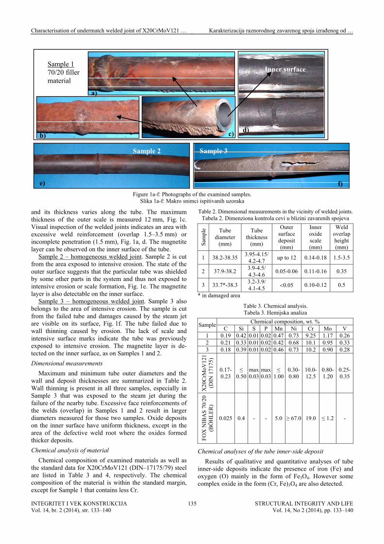
e) f) Figure 1a-f: Photographs of the examined samples.
Slika 1a-f: Makro snimci ispitivanih uzoraka
and its thickness varies along the tube. The maximum thickness of the outer scale is measured 12 mm, Fig. 1c. Visual inspection of the welded joints indicates an area with excessive weld reinforcement (overlap 1.5–3.5 mm) or incomplete penetration (1.5 mm), Fig. 1a, d. The magnetite layer can be observed on the inner surface of the tube.
Sample 2 – homogeneous welded joint. Sample 2 is cut from the area exposed to intensive erosion. The state of the outer surface suggests that the particular tube was shielded by some other parts in the system and thus not exposed to intensive erosion or scale formation, Fig. 1e. The magnetite layer is also detectable on the inner surface.
Sample 3 – homogeneous welded joint. Sample 3 also belongs to the area of intensive erosion. The sample is cut from the failed tube and damages caused by the steam jet are visible on its surface, Fig. 1f. The tube failed due to wall thinning caused by erosion. The lack of scale and intensive surface marks indicate the tube was previously exposed to intensive erosion. The magnetite layer is de-tected on the inner surface, as on Samples 1 and 2.
Dimensional measurements
Maximum and minimum tube outer diameters and the wall and deposit thicknesses are summarized in Table 2. Wall thinning is present in all three samples, especially in Sample 3 that was exposed to the steam jet during the failure of the nearby tube. Excessive face reinforcements of the welds (overlap) in Samples 1 and 2 result in larger diameters measured for those two samples. Oxide deposits on the inner surface have uniform thickness, except in the area of the defective weld root where the oxides formed thicker deposits.
Chemical analysis of material
Chemical composition of examined materials as well as the standard data for X20CrMoV121 (DIN–17175/79) steel are listed in Table 3 and 4, respectively. The chemical composition of the material is within the standard margin, except for Sample 1 that contains less Cr.
Table 2. Dimensional measurements in the vicinity of welded joints. Tabela 2. Dimenziona kontrola cevi u blizini zavarenih spojeva
Sam
ple Tube
diameter (mm)
Tube thickness
(mm)
Outer surface deposit (mm)
Inner oxide scale (mm)
Weld overlap height (mm)
1 38.2-38.35 3.95-4.15/
4.2-4.7 up to 12 0.14-0.18 1.5-3.5
2 37.9-38.2 3.9-4.5/ 4.3-4.6
0.05-0.06 0.11-0.16 0.35
3 33.7*-38.3 3.2-3.9/ 4.1-4.5 0.05 0.10-0.12 0.5
* in damaged area
Table 3. Chemical analysis. Tabela 3. Hemijska analiza
Chemical composition, wt. % Sample
C Si S P Mn Ni Cr Mo V 1 0.19 0.42 0.01 0.02 0.47 0.73 9.25 1.17 0.26 2 0.21 0.33 0.01 0.02 0.42 0.68 10.1 0.95 0.33 3 0.18 0.39 0.01 0.02 0.46 0.73 10.2 0.90 0.28
X20
CrM
oV12
1 (D
IN 1
7175
)
0.17-0.23
≤ 0.50
max0.03
max0.03
≤ 1.00
0.30-0.80
10.0-12.5
0.80-1.20
0.25-0.35
FO
X N
IBA
S 7
0/20
(B
ÖH
LE
R)
0.025 0.4 - - 5.0 ≥ 67.0 19.0 ≤ 1.2 -
Chemical analyses of the tube inner-side deposit
Results of qualitative and quantitative analyses of tube inner-side deposits indicate the presence of iron (Fe) and oxygen (O) mainly in the form of Fe3O4. However some complex oxide in the form (Cr, Fe)3O4 are also detected.
INTEGRITET I VEK KONSTRUKCIJA Vol. 14, br. 2 (2014), str. 133–140
STRUCTURAL INTEGRITY AND LIFEVol. 14, No 2 (2014), pp. 133–140
135
Characterisation of undermatch welded joint of X20CrMoV121 … Karakterizacija raznorodnog zavarenog spoja izrađenog od …
Table 4. Chemical composition - standard Tabela 4. Hemijski sastav - standard
Chemical composition, wt. % Sample
W Al Ti Cu 1 0.03 0.01 0.02 0.16 2 0.03 0.02 0.03 0.14 3 0.02 0.02 0.02 0.15
X20CrMoV121 (DIN 17175) - - - - FOX NIBAS 70/20 (BÖHLER) Nb 2.2; Fe 3.0; Co ≤ 0.08; Ti +
Mechanical properties
The average hardness of the base metal and welded joints for all examined sample are plotted in Fig. 2. In homogeneous joints, the hardness of the weld and the HAZ are almost equal, /1/. The variation of hardness along the cross-section of welded joints corresponds to the different areas within the welded joint. In the austenitic area the measured hardness is significantly lower due to presence of austenite filler material. However, lower hardness in that area can be also attributed to the prolonged exposition of the material to elevated temperatures.
0 1 2 3 4 5 6 7 8 9 10 11
180
200
220
240
260
280
300
320
340
360
380
HV
30
POSITION ON WELD
Sample 1
Sample 2
Sample 3
Figure 2. Results of the hardness measurements.
Slika 2. Rezultati izmerene tvrdoće
Results of tensile tests are summarized in Table 5. In the case of martensitic (homogeneous) joints, tensile specimens failed in the area of the base metal. In the case of Sample 1 with austenitic filler, tensile tests were cut from both areas - base metal and austenitic filler material. The tensile strength of the austenitic filler material was found to be lower than that specified by manufacture (FOX NIBAS 70/20 Böhler welding). The possible reason for the lower strength of the whole welding joint could be inadequate welding that resulted in the defective geometry of the weld joint such as incomplete penetration. The other possible reason for lower strength of the welded joint could be a long term exposure to elevated temperatures.
X20CrMoV121 (DIN 17175) 490 690-840 min 171 - WELD METAL 483 594 -
Fox NIBAS 70/20 (Böhler welding) 420 680 40
Microstructure
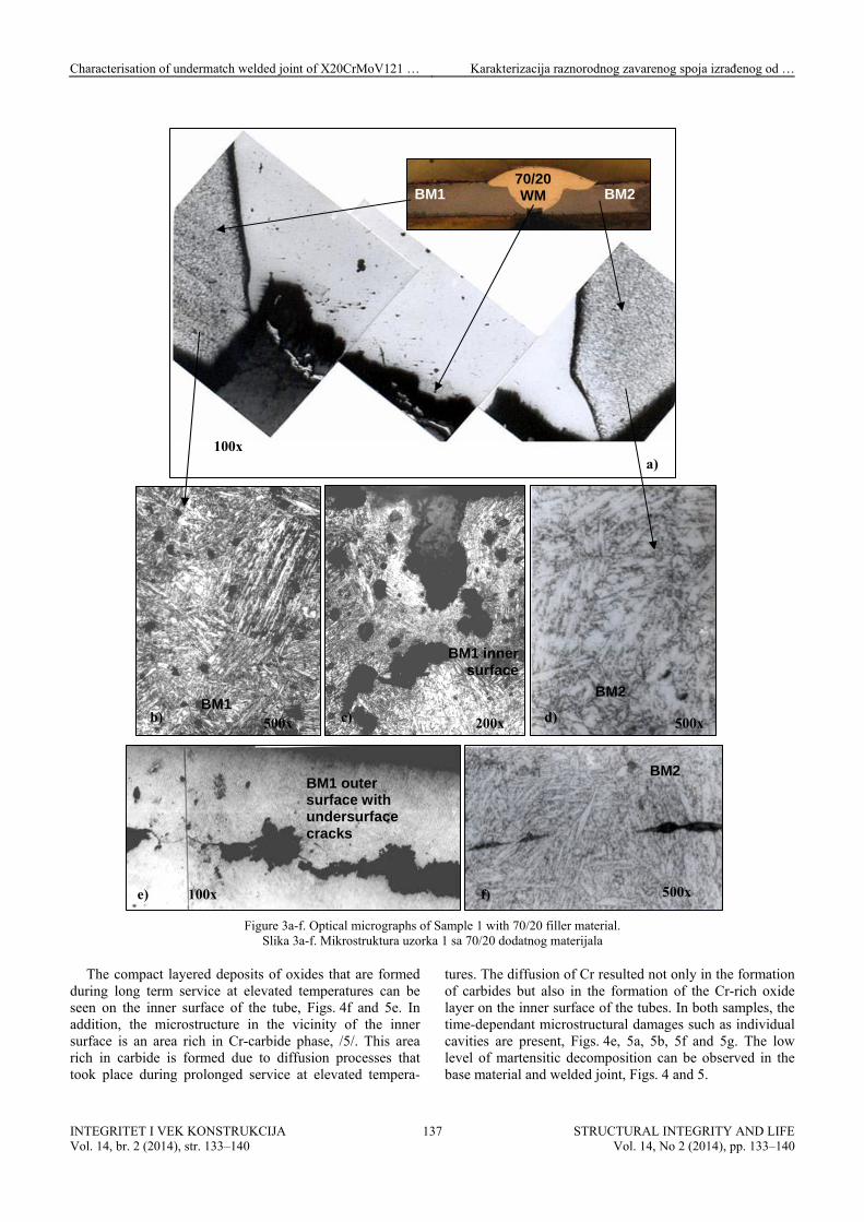
Sample 1. Optical micrographs of the different areas of the welded joint with austenitic filler material are shown in Fig. 3. The part of the SH system that had been in service for 150 000 hours is labelled as BM1, while the tube that had been in service for only 60 000 hours (a part that has replaced a failed tube) is labelled as BM2. It is obvious from Figure 3 that the root of the weld is not filled com-pletely with austenitic filler material.
The contact zone between filler and base metal contains a large quantity of carbide phase (the zone width is 0.1–0.3 mm), Fig. 3a. However, carbon depletion is present in the close vicinity do the carbide reach zone. This is more dominant in BM1 because of: (a) the inhomogeneous initial structure of BM1 with areas rich in chromium carbides; and (b) more intensive degradation processes after longer expo-sure.
The basic structure of BM1 and BM2 is combined from fine-grained and coarse-grained tempered martensite. The structure is not homogeneous across the wall thickness. The microstructural evidence of long term exposure to elevated temperatures, such as the decomposed martensitic phase and the presence of acicular ferrite and bainite can be observed in BM1. In addition, inhomogeneous distribution of the carbide phase is also visible in BM1, along with a huge number of defragmented oxide and MnS inclusions 6–76 m in length. A great number of inclusions is also visible in the BM2. The manufacturing defects such as sub-surface microcracks are visible in Fig. 3e.
In the vicinity of the welded joint, a large quantity of the cavities is present in BM1 indicating creep damage of class 3a or 4 (according to VGB-TW 507 classification), Fig. 3b and 3c. Cavities are visible in the vicinity of both inner and outer surfaces, Fig. 3c and 3e. However, the coalescence of cavities is more pronounced in the vicinity of subsurface microcracks, as shown in Fig. 3e, as well as in the vicinity of corrosion damages, Fig. 3c, and on inclusion surfaces (not shown here). Damages caused by intensive corrosion can be seen in the wide area on the inner surface of the tube. Some are filled with deposits and their depth ranges from 0.15 to 0.20 mm, while the width of the corrosion damages usually does not exceed 0.25 mm.
Macrocracks that were formed during exploitation can be seen in the austenitic filler material, Fig. 3a.
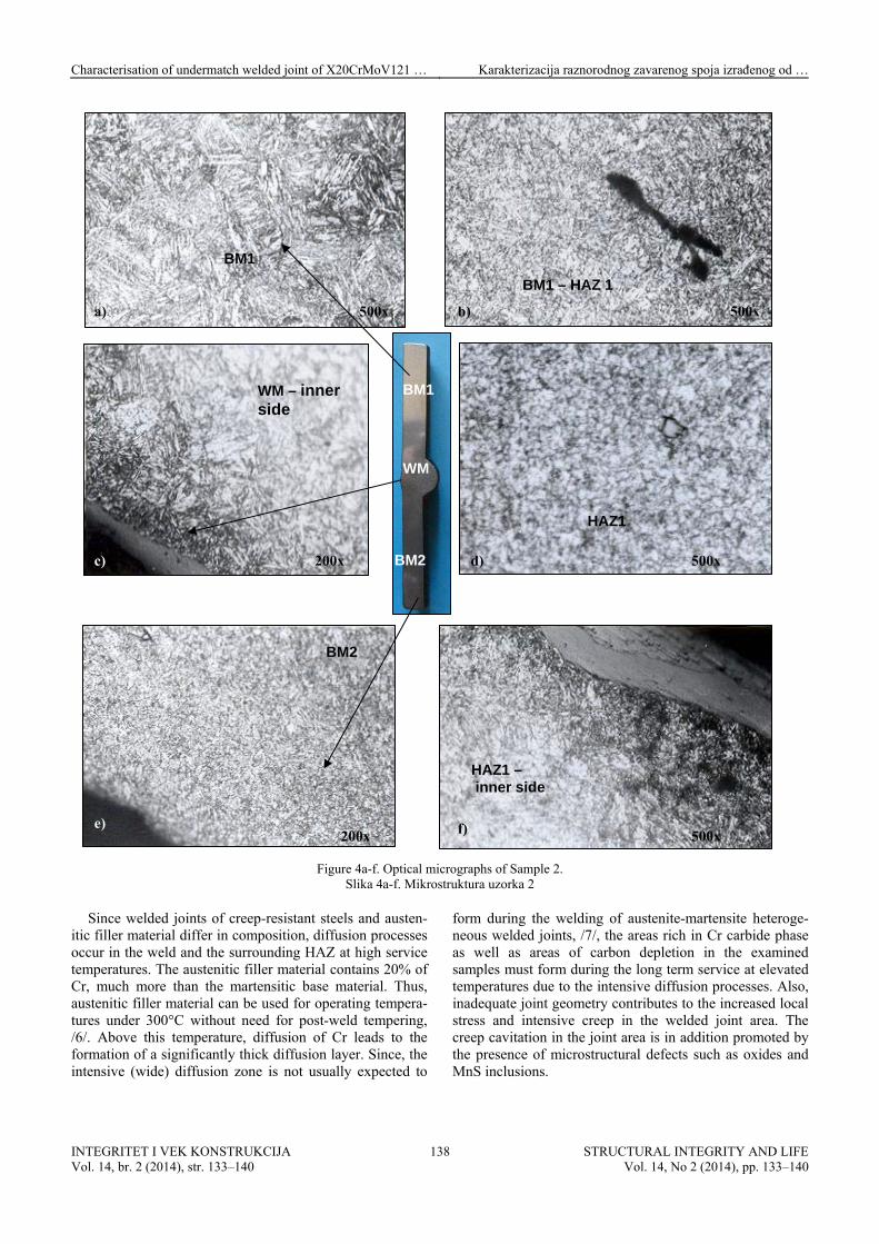
Samples 2 and 3. The basic structure of examined welds 2 and 3 with martensitic filling material is the tempered martensite. The morphology of tempered martensite depends on the maximum temperature to which it was exposed to during welding, Figs. 4 and 5.
1 2 3 4 5 6 7 8 9 1
INTEGRITET I VEK KONSTRUKCIJA Vol. 14, br. 2 (2014), str. 133–140
STRUCTURAL INTEGRITY AND LIFEVol. 14, No 2 (2014), pp. 133–140
136
Characterisation of undermatch welded joint of X20CrMoV121 … Karakterizacija raznorodnog zavarenog spoja izrađenog od …
70/20 WMBM1 BM2
100x a)
BM1 inner surface
BM2 BM1
Figure 3a-f. Optical micrographs of Sample 1 with 70/20 filler material.
Slika 3a-f. Mikrostruktura uzorka 1 sa 70/20 dodatnog materijala
The compact layered deposits of oxides that are formed during long term service at elevated temperatures can be seen on the inner surface of the tube, Figs. 4f and 5e. In addition, the microstructure in the vicinity of the inner surface is an area rich in Cr-carbide phase, /5/. This area rich in carbide is formed due to diffusion processes that took place during prolonged service at elevated tempera-
tures. The diffusion of Cr resulted not only in the formation of carbides but also in the formation of the Cr-rich oxide layer on the inner surface of the tubes. In both samples, the time-dependant microstructural damages such as individual cavities are present, Figs. 4e, 5a, 5b, 5f and 5g. The low level of martensitic decomposition can be observed in the base material and welded joint, Figs. 4 and 5.
BM1 outer surface with undersurface cracks
BM2
500x
500x 500x 200x
100x
b) c) d)
e) f)
INTEGRITET I VEK KONSTRUKCIJA Vol. 14, br. 2 (2014), str. 133–140
STRUCTURAL INTEGRITY AND LIFEVol. 14, No 2 (2014), pp. 133–140
137
Characterisation of undermatch welded joint of X20CrMoV121 … Karakterizacija raznorodnog zavarenog spoja izrađenog od …
BM1
Figure 4a-f. Optical micrographs of Sample 2.
Slika 4a-f. Mikrostruktura uzorka 2
Since welded joints of creep-resistant steels and austen-itic filler material differ in composition, diffusion processes occur in the weld and the surrounding HAZ at high service temperatures. The austenitic filler material contains 20% of Cr, much more than the martensitic base material. Thus, austenitic filler material can be used for operating tempera-tures under 300°C without need for post-weld tempering, /6/. Above this temperature, diffusion of Cr leads to the formation of a significantly thick diffusion layer. Since, the intensive (wide) diffusion zone is not usually expected to
form during the welding of austenite-martensite heteroge-neous welded joints, /7/, the areas rich in Cr carbide phase as well as areas of carbon depletion in the examined samples must form during the long term service at elevated temperatures due to the intensive diffusion processes. Also, inadequate joint geometry contributes to the increased local stress and intensive creep in the welded joint area. The creep cavitation in the joint area is in addition promoted by the presence of microstructural defects such as oxides and MnS inclusions.
BM1 – HAZ 1
WM – inner side
HAZ1
HAZ1 – inner side
BM2
500x a) 500x b)
BM1
WM
BM2 c) 200x d) 500x
e) 200x f) 500x
INTEGRITET I VEK KONSTRUKCIJA Vol. 14, br. 2 (2014), str. 133–140
STRUCTURAL INTEGRITY AND LIFEVol. 14, No 2 (2014), pp. 133–140
138
Characterisation of undermatch welded joint of X20CrMoV121 … Karakterizacija raznorodnog zavarenog spoja izrađenog od …
Figure 5a-g. Optical micrographs of Sample 3.
Slika 5a-g. Mikrostruktura uzorka 3
CONCLUSION
The welding of martensitic steels such as X20CrMo V121 with poor weldаbility, could be difficult because it requires heat treatment before and after the welding process in order to obtain welded joints of good quality. In the case of frequent forced outages it is not economically feasible to perform full heat treatment of repaired welded joints. In that case, application of austenitic filler material for repair welding has many benefits such as short welding time, no need for specific atmosphere, no preheating treatment, rela-tively easy welding process, tough and ductile welded
joints, etc. The main disadvantage of this welding technique is the inhomogeneous welded joint and lower durability compared to the homogenous martensitic welded joints, especially when exposed to prolonged service at elevated temperatures. Thus, the repair welding of martensitic steels with austenitic filler materials can be used as a temporary solution to avoid long term repair processes, and these welded joints can be replaced during the next scheduled maintenance. However, austenitic welds can be reliable for at least 20 000 hours of service as it is shown in this paper. The quality of repair welding, however, has a significant effect on their performance during exploitation.
BM1
BM2
HAZ1
HAZ2
BM2
WM
WM
WM – damage zone
WM – inner surface
BM1
a) 200x
c) 200x
b) 500x
200x d)
200x
f) 200x
e) g) 200x
INTEGRITET I VEK KONSTRUKCIJA Vol. 14, br. 2 (2014), str. 133–140
STRUCTURAL INTEGRITY AND LIFEVol. 14, No 2 (2014), pp. 133–140
139
Characterisation of undermatch welded joint of X20CrMoV121 … Karakterizacija raznorodnog zavarenog spoja izrađenog od …
REFERENCES
1. Béres, L., Balogh, A., Irmer, W., Kirk, C.S., Behavior of Weld-ed Joints of Creep-Resistant Steels at Service Temperature, Welding Research, 330-S, Nov. 2003.
2. Šijački Žeravčić, V., Bakić, G., et al., RCM in Power Plant Practice Illustrated on Observation of Material Aging and Defining of Component Life Exhaustion, Proc. of Int. Conf. Power-Gen Middle East 2002, Abu Dhabi, UAE, paper No334, 2002.
3. Fournier, B., Sauzay, M., Mottot, M., Brillet, H., Monnet, I., Pineau, A., Experimentally Based Modelling of Cyclically Induced Softening in a Martensitic Steel at High Temperature, ECCC Creep Conference, 2005, London.
4. Šijački Žeravčić, V., Bakić, G., Djukić, M., Andjelić, B., Rajičić, B., Inter. report 12-03-12.04/2004, Study of remaining life of boiler tubing system, Unit 1, TPP ‘Nikola Tesla’, University of Belgrade, Faculty of Mech. Engng. Belgrade, p.283, 2004.
5. Ennis, P.J., Modul 3 - Further Development of P91/T91 Towards Improved Steam Oxidation Resistance, 2005, ETD 2006, UK.
6. Béres, L., et al., Welding of martensitic creep-resistant steels, Welding Journal 80(8): 191-195, 2001.
7. Brozda, J., Weldаbility, characteristics and benefits of new generation creep-resistant steels and the properties of welding joints, Welding International, 18(8): 599-608, 2004.
15th International ASTM/ESIS Symposium on Fatigue and Fracture Mechanics (40th ASTM National Symposium on Fatigue and Fracture Mechanics)
Dates: Wednesday May 20 2015 - Friday May 22 2015 Location: Marriott Anaheim, Anaheim, CA Sponsored by: ASTM Committee E08 Fatigue and Fracture Deadline for Abstract Submittal: Monday December 08 2014
Objective
This symposium is intended to provide a forum for researchers and technologists from the academic, industrial and government sectors to share, discuss, and debate the latest improvements in the science, technology, and applications of fatigue and fracture. Experimental, analytical, and computational perspectives are all equally appropriate for discussion, especially given the reality that the improved understanding being sought will most likely come from a synergistic combination of advances in all three perspectives.
Submittals focusing on any and all areas of the science, technology, and applications of fatigue and fracture mechanics concepts are therefore solicited and encouraged. Areas of particular interest, that could potentially form thematic tracks within the overall symposium, include:
• Residual stress effects on service life and fatigue/fracture models and experiments
• Probabilistic methods for fatigue and fracture prediction • Verification and validation of fatigue and fracture models • Advanced experimental techniques that stretch the current test
methods and standards for fatigue and fracture characterization and could lead to new and improved approaches
• Improvements in the state-of-the-art for predicting remaining usable life and/or the onset of a fracture-related failure event
• Multi-axial and mixed mode fatigue and fracture testing and prediction
• Fatigue and fracture of components and structures produced using novel manufacturing methods
• Environmentally assisted fatigue and fracture testing and prediction
• Fatigue and fracture of medical devices
Abstract Submittal
Potential presenters/authors must submit, on-line and no later than December 8, 2014, an Abstract Submittal Form and a 250-300 word Preliminary Abstract.
Preliminary Abstract must include a clear definition of the objective of the work discussed and describe the approach being taken, pointing out material that is new and presenting sufficient details regarding results to allow assessment of the likelihood of a complete and high-quality presentation at the actual event. Neither the abstract, nor any subsequent presentation, can be commercial or proprietary in nature, nor can the material being discussed have been previously published or presented in another forum. Only a limited number of the submitted abstracts can be accommodated for presentation, so submitters are encouraged to make every effort to ensure that the Preliminary Abstract provides enough information
to allow for careful assessment of its suitability for this symposium. The decision of the Symposium Co-Chairs regarding a submission will be final and communicated to the submitter by Dec 15, 2014.
Complete the Abstract Submittal Form and submit an Abstract on-line. To ensure your abstract was received and properly logged into the ASTM database, please email Hannah Sparks ([email protected]) after submittal to let her know that an abstract has been submitted.
Accepted authors will then be required to submit a 4 to 8 page Extended Abstract to ASTM no later than March 1, 2015. The collection of Extended Abstracts will be made available, in electronic format, to all authors and attendees on the first day of the symposium. Publication of the Extended Abstracts does not preclude authors from submitting a complete technical paper to an ASTM journal (or any other journal of their choice) at a later date. At the author's discretion, reference to the Extended Abstract is both appropriate and encouraged if material contained therein is used in the final or follow-on papers.
Extended Abstracts will not be peer-reviewed or copy-edited, so accepted authors will need to strive to submit material suitable for distribution, as-submitted, at the symposium. Additional details will be available in the Instructions for Extended Abstracts that will be provided at a later date.
Extended Abstract must be submitted in order to present a paper at the symposium. No post-symposium STP is planned. Technical Chair Contact Information
Additional information on the symposium is available from Symposium Co-Chairs: Dr. Markus Heinimann Alcoa Technical Center, Alcoa Center, PA, USA e-mail: [email protected] phone: +1-724-337- 2657
Prof. Steve R. Daniewicz Mississippi State University, MS, USA e-mail: [email protected] phone: +1-662-325-7322
Prof. Stefano Beretta Politecnico di Milano, Milano, ITALY e-mail: [email protected] phone: +39-02-2399-8246
INTEGRITET I VEK KONSTRUKCIJA Vol. 14, br. 2 (2014), str. 133–140
STRUCTURAL INTEGRITY AND LIFEVol. 14, No 2 (2014), pp. 133–140