For boards, it is possible to use the calculation method explained in paragraph 10.10.4.2 of Standard EN 61439-1, IEC 61439-1. To facilitate the thermal check of the 46 range boards in the latter case, Gewiss has prepared a set of tables (on the next page) for every board version and size; these tables show the maximum dispersible power values inside every type of shell, on the basis of the consequential maximum internal overtemperature of the air. The parameters of the dispersible power in the various configurations were obtained from both laboratory tests carried out according to the method described in paragraph 10.10.4.2 of Standard EN 61439-1 (and subsequently verified according to paragraph 10.10.4.3 of Standard EN 61439-1), and the calculation method indicated in Standard IEC 60890. The tables are valid when the following parameters are respected: a) sum of board input current no greater than: a1. 1600A (if all the requisites listed below are respected); a2. 630A (if the requisites indicated in points 2 - 6 below are respected); b) maximum rated frequency of the board no greater than 60 Hz; c) sufficiently even distribution of the devices inside the board; d) rated current of each circuit no greater than 80% of the free air current (I th ) of the devices installed along the circuit itself (bear in mind that for modular devices, the free air current (I th ) usually coincides with the rated current (I n ) of the devices themselves); e) mechanical parts and devices installed so as not to prevent free air circulation; f) no conductor section less than that indicated in IEC 60364-5-52; g) for shells with ventilation openings, the section of the air output openings must be at least 1.1 times the section of the input openings; h) no more than three horizontal divisions for each board or board section; i) for shells with compartments and natural ventilation, the section of the ventilation openings in each partition must be equal to at least 50% of the horizontal section of the compartment. The check is carried out on the basis of the following points: 1) definition of the board installation conditions: single board exposed on every side, or single surface-mounting board, etc; 2) identification of the overtemperature allowed for the board, according to the maximum operating temperature of the devices to be installed in it; 3) determination of the P dix of the board (taking into account the dispersible power of the active devices to be installed in the board); 4) identification of the board (LxHxD) with dispersible power P dq , according to the conditions determined in points 1 and 2, plus the P dix already determined in point 3. To speed up the calculation, check, certification and budgeting of Gewiss boards, there is the GWPBT-Q software available in the special Gewiss Software CD or which can be downloaded directly from the website www.gewiss.com. GWPBT-Q software CHECK OF OVERTEMPERATURE INSIDE 46 RANGE UNIVERSAL BOARDS 46 1 Technical Information Version 2.1 For technical information contact the Technical Assistance Service or visit gewiss.com
Transcript
For boards, it is possible to use the calculation method explained in paragraph 10.10.4.2 of Standard EN 61439-1, IEC 61439-1.To facilitate the thermal check of the 46 range boards in the latter case, Gewiss has prepared a set of tables (on the next page) for every board version and size; these tables show the maximum dispersible power values inside every type of shell, on the basis of the consequential maximum internal overtemperature of the air. The parameters of the dispersible power in the various configurations were obtained from both laboratory tests carried out according to the method described in paragraph 10.10.4.2 of Standard EN 61439-1 (and subsequently verified according to paragraph 10.10.4.3 of Standard EN 61439-1), and the calculation method indicated in Standard IEC 60890.
The tables are valid when the following parameters are respected:a) sum of board input current no greater than: a1. 1600A (if all the requisites listed below are respected); a2. 630A (if the requisites indicated in points 2 - 6 below are respected);b) maximum rated frequency of the board no greater than 60 Hz;c) sufficiently even distribution of the devices inside the board;d) rated current of each circuit no greater than 80% of the free air current (Ith) of the devices installed along the circuit itself (bear in mind that for modular
devices, the free air current (Ith) usually coincides with the rated current (In) of the devices themselves);e) mechanical parts and devices installed so as not to prevent free air circulation;f) no conductor section less than that indicated in IEC 60364-5-52;g) for shells with ventilation openings, the section of the air output openings must be at least 1.1 times the section of the input openings;h) no more than three horizontal divisions for each board or board section;i) for shells with compartments and natural ventilation, the section of the ventilation openings in each partition must be equal to at least 50% of the horizontal
section of the compartment.
The check is carried out on the basis of the following points:1) definition of the board installation conditions: single board exposed on every side, or single surface-mounting board, etc;2) identification of the overtemperature allowed for the board, according to the maximum operating temperature of the devices to be installed in it;3) determination of the Pdix of the board (taking into account the dispersible power of the active devices to be installed in the board);4) identification of the board (LxHxD) with dispersible power Pdq, according to the conditions determined in points 1 and 2, plus the Pdix already determined in
point 3.
To speed up the calculation, check, certification and budgeting of Gewiss boards, there is the GWPBT-Q software available in the special Gewiss Software CD or which can be downloaded directly from the website www.gewiss.com.
GWPBT-Q software
CHECK OF OVERTEMPERATURE INSIDE 46 RANGE UNIVERSAL BOARDS
46
1Technical Information Version 2.1
For technical information contact the Technical Assistance Service or visit gewiss.com
Single board exposed on all sides
Single surface-mounting board
Single board with corner walls, or first/last combined board
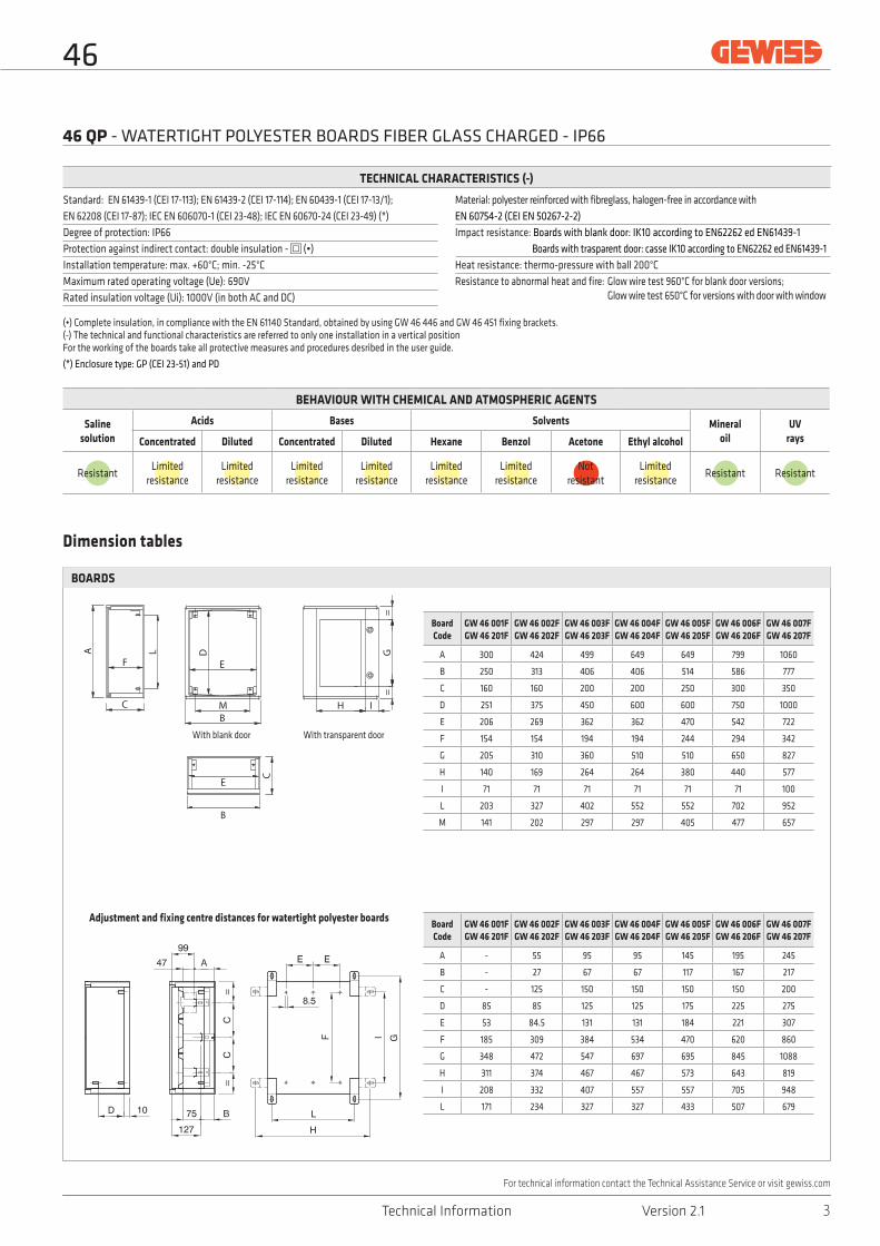
Standard: EN 61439-1 (CEI 17-113); EN 61439-2 (CEI 17-114); EN 60439-1 (CEI 17-13/1); EN 62208 (CEI 17-87); IEC EN 606070-1 (CEI 23-48); IEC EN 60670-24 (CEI 23-49) (*) Degree of protection: IP66Protection against indirect contact: double insulation - (•)Installation temperature: max. +60°C; min. -25°CMaximum rated operating voltage (Ue): 690VRated insulation voltage (Ui): 1000V (in both AC and DC)
Material: polyester reinforced with fibreglass, halogen-free in accordance with EN 60754-2 (CEI EN 50267-2-2)Impact resistance: Boards with blank door: IK10 according to EN62262 ed EN61439-1 Boards with trasparent door: casse IK10 according to EN62262 ed EN61439-1Heat resistance: thermo-pressure with ball 200°CResistance to abnormal heat and fire: Glow wire test 960°C for blank door versions; Glow wire test 650°C for versions with door with window
(•) Complete insulation, in compliance with the EN 61140 Standard, obtained by using GW 46 446 and GW 46 451 fixing brackets.(-) The technical and functional characteristics are referred to only one installation in a vertical position For the working of the boards take all protective measures and procedures desribed in the user guide.
(*) Enclosure type: GP (CEI 23-51) and PD
46
3Technical Information Version 2.1
For technical information contact the Technical Assistance Service or visit gewiss.com
Dimension tables
BOARDS
Board Code
GW 46 031-
GW 46 032GW 46 232
GW 46 033GW 46 233
GW 46 034GW 46 234
GW 46 035GW 46 235
GW 46 036GW 46 236
GW 46 037GW 46 237
A 296 420 495 645 645 795 1045
B 246 309 402 402 510 582 762
C 160 160 200 200 250 300 350
D 256 380 455 605 605 755 1005
E 206 269 362 362 470 542 722
F 157 157 197 197 247 297 347
G 205 310 360 510 510 650 827
H 140 169 264 264 380 440 577
I 71 71 71 71 71 71 100
L 203 327 402 552 552 702 952
M 141 202 297 297 405 477 657
Board Code
GW 46 031-
GW 46 032GW 46 232
GW 46 033GW 46 233
GW 46 034GW 46 234
GW 46 035GW 46 235
GW 46 036GW 46 236
GW 46 037GW 46 237
A - 55 95 95 145 195 245
B - 27 67 67 117 167 217
C - 125 150 150 150 150 200
D 65 65 65 65 200 250 300
E 191 254 347 347 453 527 699
F 228 352 427 577 577 725 968
G 348 472 547 697 695 845 1088
H 311 374 467 467 573 643 819
I 208 332 407 557 557 705 948
L 171 234 327 327 433 507 679
M - - - 270 270 335 335
Adjustment and fixing distance centres for metal watertight boards
Standard: EN 61439-1 (CEI 17-113); EN 61439-2 (CEI 17-114); EN 60439-1 (CEI 17-13/1); EN 62208 (CEI 17-87); IEC EN 606070-1 (CEI 23-48); IEC EN 60670-24 (CEI 23-49) (*) Degree of protection: IP55Protection against indirect contact:metal shell pre-arranged with earth terminal
Installation temperature: max. +60°C; min. -25°C
Impact resistance: Boards with blank door IK10 secondo EN62262 Boards with glass door IK08 secondo EN62262 Maximum rated operating voltage (Ue): 690VMaterial: sheet metal from 10/10 to 15/10, painted with epoxy-polyester powders Applications: for indoor use
(-) The technical and functional characteristics are referred to only one installation in a vertical position (*) Enclosure type: GP (CEI 23-51) and PD
46
4 Technical Information Version 2.1
For technical information contact the Technical Assistance Service or visit gewiss.com
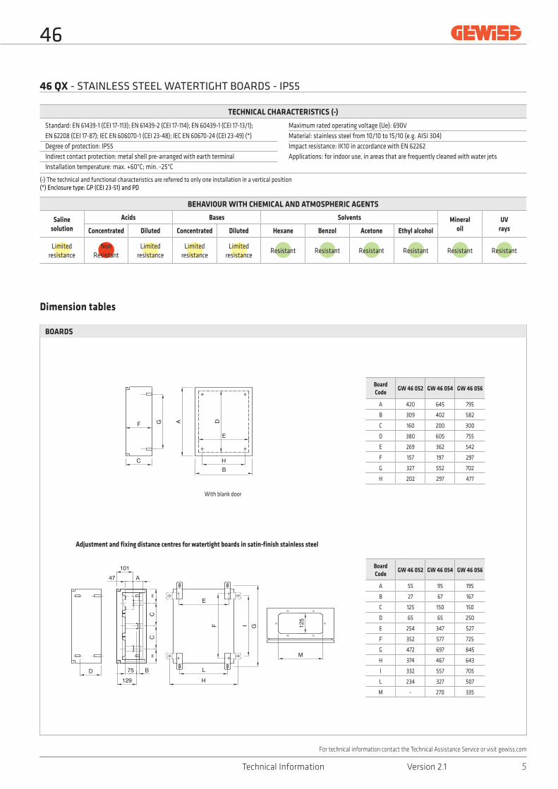
Dimension tables
BOARDS
Board Code
GW 46 052 GW 46 054 GW 46 056
A 420 645 795
B 309 402 582
C 160 200 300
D 380 605 755
E 269 362 542
F 157 197 297
G 327 552 702
H 202 297 477
Board Code
GW 46 052 GW 46 054 GW 46 056
A 55 95 195
B 27 67 167
C 125 150 150
D 65 65 250
E 254 347 527
F 352 577 725
G 472 697 845
H 374 467 643
I 332 557 705
L 234 327 507
M - 270 335
Adjustment and fixing distance centres for watertight boards in satin-finish stainless steel
Standard: EN 61439-1 (CEI 17-113); EN 61439-2 (CEI 17-114); EN 60439-1 (CEI 17-13/1); EN 62208 (CEI 17-87); IEC EN 606070-1 (CEI 23-48); IEC EN 60670-24 (CEI 23-49) (*)Degree of protection: IP55Indirect contact protection: metal shell pre-arranged with earth terminalInstallation temperature: max. +60°C; min. -25°C
Maximum rated operating voltage (Ue): 690VMaterial: stainless steel from 10/10 to 15/10 (e.g. AISI 304)Impact resistance: IK10 in accordance with EN 62262 Applications: for indoor use, in areas that are frequently cleaned with water jets
(-) The technical and functional characteristics are referred to only one installation in a vertical position (*) Enclosure type: GP (CEI 23-51) and PD
46
5Technical Information Version 2.1
For technical information contact the Technical Assistance Service or visit gewiss.com
46 QP: DISTANCES BETWEEN DOOR, INNER DOOR, BACK-MOUNTING PLATE AND PANEL
46 QM: DISTANCES BETWEEN DOOR, INNER DOOR, BACK-MOUNTING PLATE AND PANEL
46 QX: DISTANCES BETWEEN DOOR, INNER DOOR, BACK-MOUNTING PLATE AND PANEL
back-mounting plate
inner door
door door
panel
POSITION A POSITION B
back-mounting plate
inner door
door door
panel
POSITION A POSITION B
back-mounting plate
inner door
door door
panel
POSITION A POSITION B
Board dimensions
With inner door With panels
Position A Position B X
c h1 d h2 min max
310x425 31 102 50 83 22 67
405x500 31 142 50 123 25 33
405x650 31 142 50 123 25 33
515x650 31 191 50 172 35 116
585x800 31 241 50 222 35 166
800x1060 31 295 60 266 35 216
Board dimensions
With inner door With panels
Position A Position B X
c h1 d h2 min max
310x425 31 102 50 83 22 67
405x650 31 142 50 123 25 33
585x800 31 241 50 222 35 166
Dimension tables
46 QP - QM - QX
Board dimensions
With inner door With panels
Position A Position B X
c h1 d h2 min
310x425 32 96 49 79 32
405x500 32 136 49 119 32
405x650 32 136 49 119 32
515x650 32 186 49 169 32
585x800 32 236 49 219 32
800x1060 37 277 69 248 37
46
6 Technical Information Version 2.1
For technical information contact the Technical Assistance Service or visit gewiss.com
Dimension tables
FRONT CONFIGURATION
panels with windows
1-module high blank panels
perforated/solid plates with 1-module height
perforated/solid plates with 2-module height
uprights
2-module high blank panels
Panels with windows - GW 46 420 F GW 46 421 F GW 46 421 F GW 46 422 F GW 46 423 F GW 46 424 F
Single blank panels - GW 46 425 F GW 46 426 F GW 46 426 F GW 46 427 F GW 46 428 F GW 46 429 F
Double blank panels - GW 46 475 F GW 46 476 F GW 46 476 F GW 46 477 F GW 46 478 F GW 46 479 F
Uprights - GW 46 435 F GW 46 436 F GW 46 437 F GW 46 437 F GW 46 438 F GW 46 439 F
Standard: EN 61439-1 (CEI 17-113); EN 61439-2 (CEI 17-114); EN 60439-1 (CEI 17-13/1); IEC EN 606070-1 (CEI 23-48); IEC EN 60670-24 (CEI 23-49) (*)Degree of protection: IP55Protection against indirect contact: double insulation - (•)Installation temperature: max. +60°C; min. -25°CMaximum rated insulation voltage (Ui): 750V
Maximum rated operating voltage (Ue): 750VMaterial: GW PLAST 120, halogen-free in accordance with EN 60754-2 (CEI EN 50267-2-2)Impact resistance: IK08 in accordance with EN 62262 Heat resistance: thermo-pressure with ball 110°CResistance to abnormal heat and fire: Glow wire test 650°C
(•) Complete insulation, in accordance with EN 61140 Standard, obtainable with screwcaps or GW 44 621 / GW 46 446 / GW 46 451 fixing brackets.(-) The technical and functional characteristics are referred to only one installation in a vertical position (*) Enclosure type: GP (CEI 23-51) and PD
46
9Technical Information Version 2.1
For technical information contact the Technical Assistance Service or visit gewiss.com
1. Install in a DIN rail device board with a voltage and rated current less than those of the enclosures.
2. Enclosures tested with protection devices which comply with Standards EN 60898-1, EN 61008-2-1 and EN 61009-2-1.
3. Use DIN rail connection devices that are suitable for use with the sections and with the number of input and output cables.
4. For the installation of the devices, follow the directions and warnings provided in the specific sheet for each component of the enclosure.
5. Ensure that the live parts cannot be accessed once installed.
6. When carrying out the wiring operation, take care to maintain adequate isolation distances.
7. Comply with local system standards.
Additional information for PD enclosures:
GWPBT-Q: Software for the sizing and cost estimate of LV systems and enclosures/boards
The GWPBT-Q software is a fundamental aid to facilitate and speed up checks into the conformity of the boards with Standard CEI 23-51.
It allows you to check the overtemperature limits (with the relative printout of the conformity declaration) and, at the same time, permits you to draw up the cost estimates.
46
10 Technical Information Version 2.1
For technical information contact the Technical Assistance Service or visit gewiss.com