29Si solid state MAS NMR study on leaching behaviors and chemical stabilityof different Mg-silicate structures for CO2 sequestrationGuanhe Rima,b, Ariane Katrina Marchesed, Phillip Stallworthd, Steven G. Greenbaumd,Ah-Hyung Alissa Parka,b,c,⁎
a Department of Earth and Environmental Engineering, Columbia University, New York, NY 10027, USAb Lenfest Center for Sustainable Energy, The Earth Institute, New York, NY 10027, USAc Department of Chemical Engineering, Columbia University, New York, NY 10027, USAd Department of Physics & Astronomy, Hunter College of the City University of New York, New York, NY 10065, USA
H I G H L I G H T S
• Dissolution mechanisms of heat-treated serpentine were studied by29Si MAS NMR.
• Chemical stabilities of different sili-cate structures (Q0–Q4) were de-termined.
• The amorphous Q1 and Q2 structureswere most reactive in carbonic acid.
• This study identified different reactionpathways for CO2 sequestration.
G R A P H I C A L A B S T R A C T
A R T I C L E I N F O
Keywords:Carbon mineralizationSilicate29Si MAS NMRLeaching behaviorsHeat treatment
A B S T R A C T
Silicon is one of the most earth abundant elements, and thus, the fate and reactivity of silicate materials are oftenimportant for various energy and environmental technologies including carbon sequestration, where CO2 is cap-tured and stored as a thermodynamically stable solid carbonate phase. Thus, understanding the structures andchemistries of different silicate phases has become an important research aim. In this study, the changes in thesilicate structures (Q0–Q4) of heat-treated Mg-bearing mineral (serpentine) exposed to a CO2-water system (carbonicacid) was investigated using 29Si MAS NMR, XRPD and ICP-OES and the identified structures were employed toexplain complex leaching behaviors of silicate materials. The 29Si MAS NMR and XRPD analysis indicated that theheat-treated serpentine is a mixture of amorphous (Q1: dehydroxylate I, Q2: enstatite, Q4: silica) and crystalline (Q0:forsterite, Q3: dehydroxylate II and serpentine) phase, while natural serpentine mineral has single crystalline Q3
silicate structure. The leaching experiments showed that both Mg and Si in the amorphous silicate structures (Q1:dehydroxylate I, Q2: enstatite) are more soluble than those in crystalline phase (Q0: forsterite, Q3: dehydroxylate IIand serpentine). Therefore, tuning the silicate structure towards Q1 and Q2 would significantly improve carbonsequestration potential of silicate minerals, whereas silicate materials with Q3 structure would provide great che-mical stabilities in acidic conditions. The solubilities of silicate structures were in the order of Q1 (dehydroxylateI) > Q2 (enstatite) ≫ Q0 (forsterite) > Q3 (dehydroxylate II) > Q3 (serpentine) and this finding can be used tobetter design a wide range of energy and environmental materials and reaction systems.
https://doi.org/10.1016/j.cej.2020.125204Received 22 January 2020; Received in revised form 20 April 2020; Accepted 22 April 2020
⁎ Corresponding author at: Department of Earth and Environmental Engineering and Department of Chemical Engineering, Columbia University, New York, NY10027, USA.
Since the industrial revolution, the atmospheric CO2 concentrationhas steadily increased due to the combustion of fossil fuels, reaching410 ppm in September 2019 [1]. Researchers have correlated the in-tensification of climate change with the increase of atmospheric CO2
concentration [2]. According to the 2018 IPCC report [3], it was re-cognized that the anthropogenic greenhouse gas emissions caused byhuman activities are major drivers for global warming of 1.0 °C abovethe pre-industrial level. With the continued reliance on fossil fuels invarious parts of the world, atmospheric CO2 is likely to further increase,resulting in 1.5 °C of global warming between 2030 and 2052 withlong-term changes in climate-related natural systems, such as sea levelrise [3]. The natural carbon cycle process can potentially slow down theincrease rate of atmospheric CO2 concentration [4], but engineeredsolutions are also needed to reduce CO2 emissions. Due to its un-precedented scale, the mitigation of climate change requires a widerange of multifaceted solutions. The Mission Innovation lists the fol-lowing eight innovation challenges to encourage the global efforts toaccelerate the research and development in addressing climate changemitigation: (1) smart grid, (2) off-grid access to electricity, (3) carboncapture, (4) sustainable biofuels, (5) converting sunlight, (6) cleanenergy materials, (7) affordable heating and cooling of buildings, and(8) renewable and clean hydrogen [5,6]. In particular, we have beenfocusing on the development of novel materials and separation andreaction pathways for Carbon Capture, Utilization and Storage (CCUS)and energy storage technologies.
When developing CCUS or energy storage (e.g., novel electrolytesfor batteries) technologies, materials selection is very important sincethe availabilities of natural resources and their engineered forms arekeys to develop large-scale energy and environmental technologies.Silicon is the second most abundant element in the Earth’s crust (about28 wt%) next to oxygen and they mostly exist as silicate mineralsforming > 90% of the Earth crust [7]. Thus, as shown in Fig. 1, thestudy of various silicate materials in terms of their structures and re-activities has become one of the most important fundamental studiesfor sustainable energy and environmental research.
For example, carbon mineralization, which converts CO2 to ther-modynamically stable solid carbonate form is one of emerging CCUStechnologies with long-term stability. The carbon mineralization
scheme was proposed by Seifritz [8] as an alternative approach to se-quester CO2 in geologic formations. This is a chemically enhanced formof the natural weathering process between natural silicate minerals andCO2. Earth abundant minerals including serpentine (Mg3Si2O5(OH)4)are estimated to have a CO2 sequestration potential over 10,000 Gt C[9,10]. The overall reaction produces a long-lived metal-carbonatephase via a thermodynamically favorable reaction pathway [5,11]. Ifthe carbon mineralization process is performed in an engineered reactorsystem, high-purity products, such as green construction materials andhigh surface area silica, can be produced with tailored chemical andphysical properties while sequestering CO2. Currently, the global con-struction materials market is tremendous (> 50 billion tons producedannually) [11] and a recent market assessment estimated that thecarbonate-based construction materials may have the potential to uti-lize 3–6 Gt of CO2 with annual revenues of $1 trillion by 2030 [5,12].Carbon mineralization can also be performed using alkaline industrialwastes (e.g., steel slag and cement kiln dust) [11]. Thus, carbon mi-neralization is considered to be the most energy-efficient and eco-nomical CCUS pathway with multiple environmental benefits at thistime [11].
CO2 reaction with silicate minerals is quite complex since manysilicate structures exist depending on the reactive environments. Forinstance, earth abundant Mg-bearing mineral, serpentine(Mg3Si2O5(OH)4), consists of 1:1 alternatively stacked tetrahedral (si-lica-like) and octahedral (brucite-like) sheets and it can react with CO2
via following steps: (i) Mg2+ extraction from the silicate structure inaqueous phase by acid (ion exchange between Mg2+ and H+), and (ii)precipitation reaction between extracted Mg2+
(aq) and dissolved carbondioxide (CO3
2–(aq)) forming solid MgCO3(s) phases. The main kinetic
barrier for carbon sequestration with Mg-silicate minerals (e.g., ser-pentine) is considered to be the mineral dissolution step because of thelow reactivity of natural silicate minerals [13]. A number of studieshave focused on the activation of serpentine via heat-treatment thateffectively alters the silicate structures to increase the leaching rate ofMg and other metals from silicate minerals [14–23].
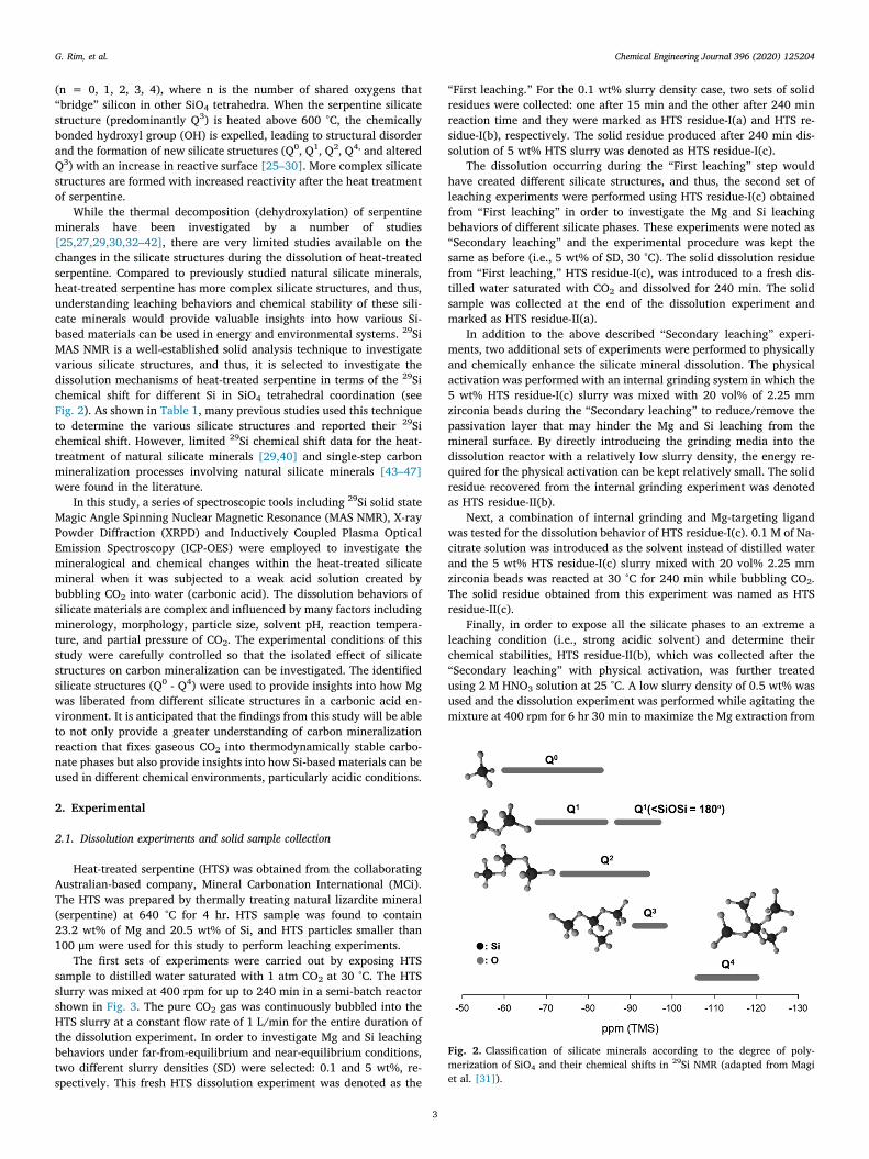
Most silicate minerals consist of SiO4 tetrahedra, which may exist asisolated structures or interconnected complicated structures [24]. Theway the SiO4 tetrahedra structures are linked determines the overallmineral structures. Thus, silicate minerals are generally classified basedon the degree of polymerization of SiO4 and denoted as symbol Qn
Fig. 1. Flows of C and Si-bearing materials in the Earth and engineered energy and environmental systems.
G. Rim, et al. Chemical Engineering Journal 396 (2020) 125204
2
(n = 0, 1, 2, 3, 4), where n is the number of shared oxygens that“bridge” silicon in other SiO4 tetrahedra. When the serpentine silicatestructure (predominantly Q3) is heated above 600 °C, the chemicallybonded hydroxyl group (OH) is expelled, leading to structural disorderand the formation of new silicate structures (Q0, Q1, Q2, Q4, and alteredQ3) with an increase in reactive surface [25–30]. More complex silicatestructures are formed with increased reactivity after the heat treatmentof serpentine.
While the thermal decomposition (dehydroxylation) of serpentineminerals have been investigated by a number of studies[25,27,29,30,32–42], there are very limited studies available on thechanges in the silicate structures during the dissolution of heat-treatedserpentine. Compared to previously studied natural silicate minerals,heat-treated serpentine has more complex silicate structures, and thus,understanding leaching behaviors and chemical stability of these sili-cate minerals would provide valuable insights into how various Si-based materials can be used in energy and environmental systems. 29SiMAS NMR is a well-established solid analysis technique to investigatevarious silicate structures, and thus, it is selected to investigate thedissolution mechanisms of heat-treated serpentine in terms of the 29Sichemical shift for different Si in SiO4 tetrahedral coordination (seeFig. 2). As shown in Table 1, many previous studies used this techniqueto determine the various silicate structures and reported their 29Sichemical shift. However, limited 29Si chemical shift data for the heat-treatment of natural silicate minerals [29,40] and single-step carbonmineralization processes involving natural silicate minerals [43–47]were found in the literature.
In this study, a series of spectroscopic tools including 29Si solid stateMagic Angle Spinning Nuclear Magnetic Resonance (MAS NMR), X-rayPowder Diffraction (XRPD) and Inductively Coupled Plasma OpticalEmission Spectroscopy (ICP-OES) were employed to investigate themineralogical and chemical changes within the heat-treated silicatemineral when it was subjected to a weak acid solution created bybubbling CO2 into water (carbonic acid). The dissolution behaviors ofsilicate materials are complex and influenced by many factors includingminerology, morphology, particle size, solvent pH, reaction tempera-ture, and partial pressure of CO2. The experimental conditions of thisstudy were carefully controlled so that the isolated effect of silicatestructures on carbon mineralization can be investigated. The identifiedsilicate structures (Q0 - Q4) were used to provide insights into how Mgwas liberated from different silicate structures in a carbonic acid en-vironment. It is anticipated that the findings from this study will be ableto not only provide a greater understanding of carbon mineralizationreaction that fixes gaseous CO2 into thermodynamically stable carbo-nate phases but also provide insights into how Si-based materials can beused in different chemical environments, particularly acidic conditions.
2. Experimental
2.1. Dissolution experiments and solid sample collection
Heat-treated serpentine (HTS) was obtained from the collaboratingAustralian-based company, Mineral Carbonation International (MCi).The HTS was prepared by thermally treating natural lizardite mineral(serpentine) at 640 °C for 4 hr. HTS sample was found to contain23.2 wt% of Mg and 20.5 wt% of Si, and HTS particles smaller than100 μm were used for this study to perform leaching experiments.
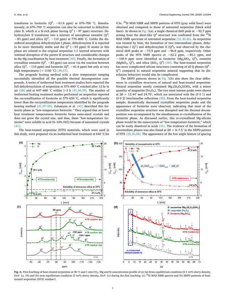
The first sets of experiments were carried out by exposing HTSsample to distilled water saturated with 1 atm CO2 at 30 °C. The HTSslurry was mixed at 400 rpm for up to 240 min in a semi-batch reactorshown in Fig. 3. The pure CO2 gas was continuously bubbled into theHTS slurry at a constant flow rate of 1 L/min for the entire duration ofthe dissolution experiment. In order to investigate Mg and Si leachingbehaviors under far-from-equilibrium and near-equilibrium conditions,two different slurry densities (SD) were selected: 0.1 and 5 wt%, re-spectively. This fresh HTS dissolution experiment was denoted as the
“First leaching.” For the 0.1 wt% slurry density case, two sets of solidresidues were collected: one after 15 min and the other after 240 minreaction time and they were marked as HTS residue-I(a) and HTS re-sidue-I(b), respectively. The solid residue produced after 240 min dis-solution of 5 wt% HTS slurry was denoted as HTS residue-I(c).
The dissolution occurring during the “First leaching” step wouldhave created different silicate structures, and thus, the second set ofleaching experiments were performed using HTS residue-I(c) obtainedfrom “First leaching” in order to investigate the Mg and Si leachingbehaviors of different silicate phases. These experiments were noted as“Secondary leaching” and the experimental procedure was kept thesame as before (i.e., 5 wt% of SD, 30 °C). The solid dissolution residuefrom “First leaching,” HTS residue-I(c), was introduced to a fresh dis-tilled water saturated with CO2 and dissolved for 240 min. The solidsample was collected at the end of the dissolution experiment andmarked as HTS residue-II(a).
In addition to the above described “Secondary leaching” experi-ments, two additional sets of experiments were performed to physicallyand chemically enhance the silicate mineral dissolution. The physicalactivation was performed with an internal grinding system in which the5 wt% HTS residue-I(c) slurry was mixed with 20 vol% of 2.25 mmzirconia beads during the “Secondary leaching” to reduce/remove thepassivation layer that may hinder the Mg and Si leaching from themineral surface. By directly introducing the grinding media into thedissolution reactor with a relatively low slurry density, the energy re-quired for the physical activation can be kept relatively small. The solidresidue recovered from the internal grinding experiment was denotedas HTS residue-II(b).
Next, a combination of internal grinding and Mg-targeting ligandwas tested for the dissolution behavior of HTS residue-I(c). 0.1 M of Na-citrate solution was introduced as the solvent instead of distilled waterand the 5 wt% HTS residue-I(c) slurry mixed with 20 vol% 2.25 mmzirconia beads was reacted at 30 °C for 240 min while bubbling CO2.The solid residue obtained from this experiment was named as HTSresidue-II(c).
Finally, in order to expose all the silicate phases to an extreme aleaching condition (i.e., strong acidic solvent) and determine theirchemical stabilities, HTS residue-II(b), which was collected after the“Secondary leaching” with physical activation, was further treatedusing 2 M HNO3 solution at 25 °C. A low slurry density of 0.5 wt% wasused and the dissolution experiment was performed while agitating themixture at 400 rpm for 6 hr 30 min to maximize the Mg extraction from
Fig. 2. Classification of silicate minerals according to the degree of poly-merization of SiO4 and their chemical shifts in 29Si NMR (adapted from Magiet al. [31]).
G. Rim, et al. Chemical Engineering Journal 396 (2020) 125204
3
HTS residue-II(b). The strong acid-treated solid residue was denoted asHTS residue-A. The detailed summary of experimental conditions andsolid sample notations are given in Table 2.
2.2. Determination of dissolution kinetics and identification of silicatestructures
During each dissolution experiment, approximately 120 μL of slurrysamples were taken at a given time interval, and the slurry sampleswere quickly filtered using a 0.2 μm syringe filter and diluted by 2%nitric acid to prevent any precipitation. The samples were analyzed byICP-OES to determine the Mg and Si concentrations in the liquid phaseproviding the leaching kinetics of different Mg-silicate materials. At theend of each leaching experiment, the slurry was filtered to collect thesolid residue and it was washed with distilled water and ethanol severaltimes. Then, the washed solid residue was dried in a vacuum oven at70 °C overnight for the subsequent 29Si solid state MAS NMR and XRPDanalyses. To determine crystal structure(s) of each solid residue, thediffraction pattern was collected in the range of 5-70° 2θ with a stepsize of 0.05° and scan time of 0.5 s using the XRPD (X2, Scintag, Inc.).
29Si (spin 1/2) MAS NMR measurements were performed using a3.2 mm Chemagnetics broadband MAS probe, a Varian/Agilent DirectDrive 300 MHz spectrometer operating at a Larmor frequency near59.9 MHz within a magnetic field of 7.1T. NMR samples were preparedby packing each solid residue listed in Table 2 into a 3.2 mm zirconiarotor in air at STP. During measurements, compressed dry air was usedfor both MAS and purge. Free induction nuclear magnetization decayswere recorded under a MAS rate of 20 kHz with a single pulse directpolarization sequence (pulse – acquire – recycle delay). High power radiofrequency pulses of 3.5 μs (which is less than the π/2 benchmark) wereemployed for each measurement. Under these conditions, a recycledelay of 5 s was adequate to prevent signal saturation. Depending onthe silicate content, typically 30,000 to 50,000 scans were averaged perspectrum. All spectra were referenced to the 29Si resonance of tetra-methylsilane (neat).
Each 29Si MAS spectrum was analyzed as a composite of weightedcomponent Qn lineshapes. The Qn MAS lineshapes consist of a central
Table 129Si chemical shifts of various silicate structures.
Structure Compound Chemical Shift (ppm) References
Smith et al.[48]Smith & Blackwell[51]Smith & Blackwell[51]Smith & Blackwell[51]Fyfe et al.[52]Smith & Blackwell[51]Leonardelli et al.[53]Chemtob et al.[54]
Fig. 3. Semi-batch dissolution reactor with CO2 bubbling.
G. Rim, et al. Chemical Engineering Journal 396 (2020) 125204
4
isotropic resonance (within about −60 ppm to −120 ppm) flanked byspinning sidebands (near −400 ppm and +200 ppm). All peaks werefit by Voight-type lineshapes [55]. The distribution of different silicatestructures/phases was obtained in the usual way through assignment(by identifying the isotropic chemical shift) and integration for each Qn
unit within the spectrum. Fig. S.1 illustrates the deconvolution proce-dure for an HTS sample.
3. Results and discussion
3.1. Development of different silicate structures during heat-treatment ofserpentine
The structural changes of silicate materials (e.g., serpentine) highlydepend on the maximum thermal treatment temperature and theheating modes (i.e., prograde heating with a slow ramping rate (e.g.,5 °C/min) or isothermal heating). A thermal decomposition sequence of
Table 2Overall experiment condition and name of solid residue.
Exp# Acid Slurry Density (wt%)
Reaction time (min) In-situ physical and chemicalenhancement
Name of solidresidues
First leaching 1a 1 atm CO2 bubbling (carbonic acid,H2CO3)
a Starting material of secondary leaching with and without physical and chemical enhancements.b Starting material of strong acid leaching.
Fig. 4. Schematic diagram of thermal decomposition sequence of serpentine with the 29Si chemical shifts of the various phase, reproduced from MecKenzie andMeinhold [40].
G. Rim, et al. Chemical Engineering Journal 396 (2020) 125204
5
different serpentine polymorphs (i.e., lizardite, chrysotile, antigorite)during prograde heating has been investigated by a number of re-searchers using X-ray Powder Diffraction (XRPD) and simultaneousThermalgravimetric and Differential Thermal Analysis (TGA/DTA)[25,27,29,30,32–39]. Generally, the dehydration of serpentine mineraloccurs up to 200 °C, and next, the dehydroxylation (the removal of OHgroups producing water) proceeds in the range of 600–800 °C. Duringthe dehydroxylation step, the crystal structure of serpentine becomesdisrupted and transformed into an amorphous phase. Further heatingabove 800 °C leads to the formation of crystalline forsterite (Mg2SiO4)and enstatite (Mg2Si2O6) from their amorphous phase. The formation offorsterite (< 800 °C) precedes enstatite (> 800 °C) because of lowerglass transition temperature (Tg) of forsterite than enstatite [30] and
the formation of enstatite seemingly requires a full dehydroxylation ofserpentine mineral [26,30,56]. While these studies performed usingXRPD were very useful in identifying different silicate phases during theheat treatment of serpentine, this method is limited to crystallinephases and cannot provide insights into amorphous or meta-crystallinephases.
Thus, 29Si and 25Mg MAS NMR have been proposed to investigatethe amorphous and transient phases. MacKenzie and Meinhold pro-posed the detailed thermal decomposition sequences of serpentine in-cluding the formation of two intermediate phases (dehydroxylate I andII) that would ultimately form forsterite and enstatite crystals (Fig. 4)[40]. Dehydroxylate I is an Mg-rich amorphous phase, characterized byQ1 (−73 ppm) structure. This phase is formed at 600–650 °C, and it
Fig. 5. (a) 29Si MAS NMR spectra and (b) XRPD patterns of serpentine (lizardite) and heat-treated serpentine which is used in this study.
G. Rim, et al. Chemical Engineering Journal 396 (2020) 125204
6
transforms to forsterite (Q0, −61.6 ppm) at 670–700 °C. Simulta-neously, at 670–700 °C serpentine can also be converted to dehydrox-ylate II, which is a Si-rich phase having Q3 (−97 ppm) structure. De-hydroxylate II transforms into a mixture of amorphous enstatite (Q2,−83 ppm) and silica (Q4, −110 ppm) at 770–800 °C. Unlike the dis-ordered amorphous dehydroxylate I phase, dehydroxylate II is reportedto be more thermally stable and the Q3 (−93 ppm) Si atoms in thisphase are related to the original serpentine 1:1 layered structure withminimal disruption of the parent Si structure and considerable changesin the Mg coordination by heat treatment [40]. Finally, the formation ofcrystalline enstatite (Q2, −83 ppm) can occur via the reaction betweensilica (Q4, −110 ppm) and forsterite (Q0, −61.6 ppm) but only at veryhigh temperatures (> 1150 °C) [40,57].
The prograde heating method with a slow temperature rampingsuccessfully identified all the possible thermal decomposition com-pounds. A series of isothermal heat treatment studies have reported thefull dehydroxylation of serpentine at 575–600 °C reached after 12 hr inair [58] and at 647–660 °C within 1–3 h [41,56,59]. The number ofisothermal heating treatment studies performed on serpentine reportedthe recrystallization of forsterite at 575–650 °C, which is significantlylower than the recrystallization temperature identified by the progradeheating method [41,57–59]. Zulumyan et al. [41] described this for-sterite phase as “low-temperature forsterite.” They argued that at lowerheat treatment temperatures forsterite forms nano-sized crystals anddoes not grow the crystal size, and thus, these “low-temperature for-sterite” were soluble in acid (6–10% HCl) because of nanosized crystals[41].
The heat-treated serpentine (HTS) materials, which were used inthis study, were prepared via an isothermal heat treatment at 640 °C for
4 hr. 29Si MAS NMR and XRPD patterns of HTS (gray solid lines) wereobtained and compared to those of untreated serpentine (black solidlines). As shown in Fig. 5(a), a single chemical shift peak at −92.7 ppmarising from the sheet-like Q3 structure was confirmed from the 29SiMAS NMR spectrum of untreated serpentine [31,40,46]. As serpentinewas treated by heat, the formation of two intermediate phases, dehy-droxylate I (Q1) and dehydroxylate II (Q3), was observed by the che-mical shift peaks at −73.9 ppm and −96.8 ppm, respectively. Otherpeaks of the HTS NMR spectra at −62.2 ppm, −85.1 ppm, and−106.9 ppm were identified as forsterite (Mg2SiO4, Q0), enstatite(MgSiO3, Q2), and silica (SiO2, Q4) [40]. The heat-treated serpentinehas more complicated silicate structures consisting of all Q phases (Q0 -Q4) compared to natural serpentine mineral suggesting that its dis-solution behaviors would also be complicated.
The XRPD patterns shown in Fig. 5(b) also show the clear differ-ences in crystalline structures of natural and heat-treated serpentine.Natural serpentine mostly contained Mg3(Si2O5)(OH)4 with a minorquantity of magnetite (Fe3O4). The two most intense peaks were shownat 2θ = 12.44° and 24.70°, which are associated with the (0 0 1) and(0 0 2) interlamellar reflections [30]. From the heat-treated serpentinesample, dramatically decreased crystalline serpentine peaks and theappearance of forsterite were observed, indicating that most of thecrystalline serpentine structure was disrupted and the thermal decom-position was accompanied by the simultaneous re-crystallization of theforsterite phase. As discussed earlier, this re-crystallized Mg-silicatephase would be the nanocrystals of “low-temperature forsterite,” whichcan be easily dissolved in acids [41]. The evidence of the formation ofintermediate phases was also found at 2θ = 6–7.5° in the XRPD patternof HTS [25,30,58]. The appearance of the low angle feature (d spacing
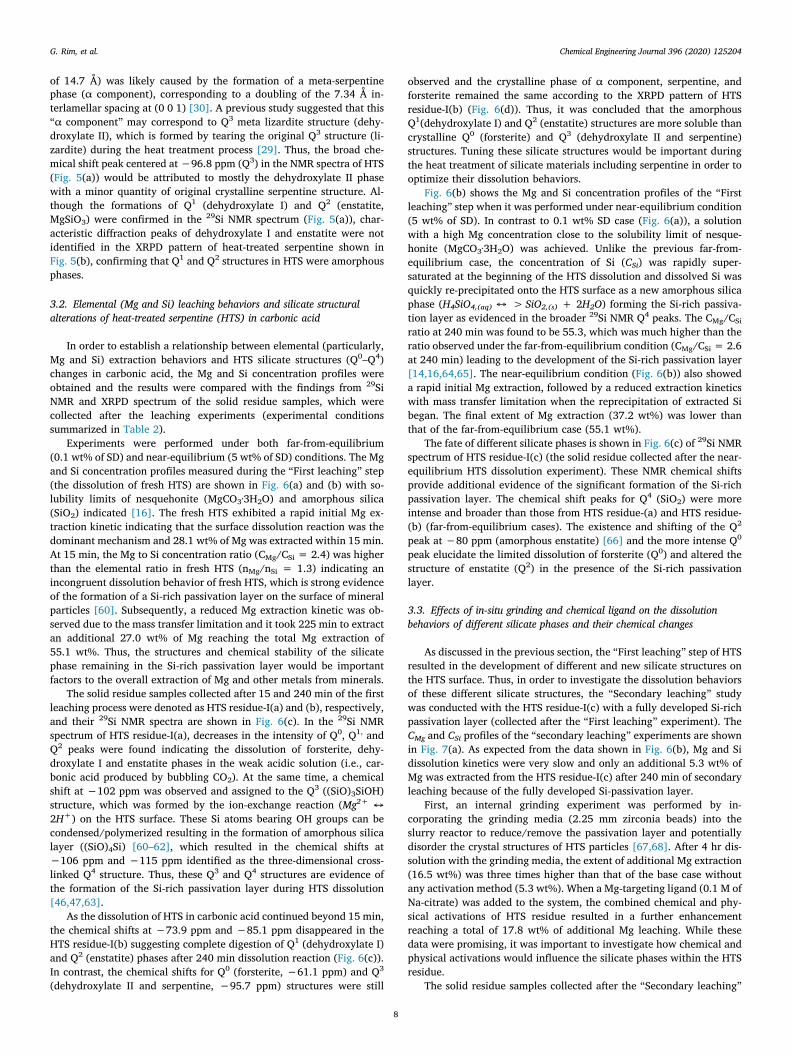
Fig. 6. First leaching of heat-treated serpentine at 30 °C and 1 atm CO2. Mg and Si concentration profile of (a) far-from-equilibrium condition (0.1 wt% slurry density,Ex#: 1a, 1b) and (b) near-equilibrium condition (5 wt% slurry density, Ex#: 1c) during the first leaching. (c) 29Si MAS NMR spectra and (b) XRPD patterns of heat-treated serpentine (HTS) residue-I.
G. Rim, et al. Chemical Engineering Journal 396 (2020) 125204
7
of 14.7 Å) was likely caused by the formation of a meta-serpentinephase (α component), corresponding to a doubling of the 7.34 Å in-terlamellar spacing at (0 0 1) [30]. A previous study suggested that this“α component” may correspond to Q3 meta lizardite structure (dehy-droxylate II), which is formed by tearing the original Q3 structure (li-zardite) during the heat treatment process [29]. Thus, the broad che-mical shift peak centered at −96.8 ppm (Q3) in the NMR spectra of HTS(Fig. 5(a)) would be attributed to mostly the dehydroxylate II phasewith a minor quantity of original crystalline serpentine structure. Al-though the formations of Q1 (dehydroxylate I) and Q2 (enstatite,MgSiO3) were confirmed in the 29Si NMR spectrum (Fig. 5(a)), char-acteristic diffraction peaks of dehydroxylate I and enstatite were notidentified in the XRPD pattern of heat-treated serpentine shown inFig. 5(b), confirming that Q1 and Q2 structures in HTS were amorphousphases.
3.2. Elemental (Mg and Si) leaching behaviors and silicate structuralalterations of heat-treated serpentine (HTS) in carbonic acid
In order to establish a relationship between elemental (particularly,Mg and Si) extraction behaviors and HTS silicate structures (Q0–Q4)changes in carbonic acid, the Mg and Si concentration profiles wereobtained and the results were compared with the findings from 29SiNMR and XRPD spectrum of the solid residue samples, which werecollected after the leaching experiments (experimental conditionssummarized in Table 2).
Experiments were performed under both far-from-equilibrium(0.1 wt% of SD) and near-equilibrium (5 wt% of SD) conditions. The Mgand Si concentration profiles measured during the “First leaching” step(the dissolution of fresh HTS) are shown in Fig. 6(a) and (b) with so-lubility limits of nesquehonite (MgCO3·3H2O) and amorphous silica(SiO2) indicated [16]. The fresh HTS exhibited a rapid initial Mg ex-traction kinetic indicating that the surface dissolution reaction was thedominant mechanism and 28.1 wt% of Mg was extracted within 15 min.At 15 min, the Mg to Si concentration ratio (CMg/CSi = 2.4) was higherthan the elemental ratio in fresh HTS (nMg/nSi = 1.3) indicating anincongruent dissolution behavior of fresh HTS, which is strong evidenceof the formation of a Si-rich passivation layer on the surface of mineralparticles [60]. Subsequently, a reduced Mg extraction kinetic was ob-served due to the mass transfer limitation and it took 225 min to extractan additional 27.0 wt% of Mg reaching the total Mg extraction of55.1 wt%. Thus, the structures and chemical stability of the silicatephase remaining in the Si-rich passivation layer would be importantfactors to the overall extraction of Mg and other metals from minerals.
The solid residue samples collected after 15 and 240 min of the firstleaching process were denoted as HTS residue-I(a) and (b), respectively,and their 29Si NMR spectra are shown in Fig. 6(c). In the 29Si NMRspectrum of HTS residue-I(a), decreases in the intensity of Q0, Q1, andQ2 peaks were found indicating the dissolution of forsterite, dehy-droxylate I and enstatite phases in the weak acidic solution (i.e., car-bonic acid produced by bubbling CO2). At the same time, a chemicalshift at −102 ppm was observed and assigned to the Q3 ((SiO)3SiOH)structure, which was formed by the ion-exchange reaction (Mg2+ ↔2H+) on the HTS surface. These Si atoms bearing OH groups can becondensed/polymerized resulting in the formation of amorphous silicalayer ((SiO)4Si) [60–62], which resulted in the chemical shifts at−106 ppm and −115 ppm identified as the three-dimensional cross-linked Q4 structure. Thus, these Q3 and Q4 structures are evidence ofthe formation of the Si-rich passivation layer during HTS dissolution[46,47,63].
As the dissolution of HTS in carbonic acid continued beyond 15 min,the chemical shifts at −73.9 ppm and −85.1 ppm disappeared in theHTS residue-I(b) suggesting complete digestion of Q1 (dehydroxylate I)and Q2 (enstatite) phases after 240 min dissolution reaction (Fig. 6(c)).In contrast, the chemical shifts for Q0 (forsterite, −61.1 ppm) and Q3
(dehydroxylate II and serpentine, −95.7 ppm) structures were still
observed and the crystalline phase of α component, serpentine, andforsterite remained the same according to the XRPD pattern of HTSresidue-I(b) (Fig. 6(d)). Thus, it was concluded that the amorphousQ1(dehydroxylate I) and Q2 (enstatite) structures are more soluble thancrystalline Q0 (forsterite) and Q3 (dehydroxylate II and serpentine)structures. Tuning these silicate structures would be important duringthe heat treatment of silicate materials including serpentine in order tooptimize their dissolution behaviors.
Fig. 6(b) shows the Mg and Si concentration profiles of the “Firstleaching” step when it was performed under near-equilibrium condition(5 wt% of SD). In contrast to 0.1 wt% SD case (Fig. 6(a)), a solutionwith a high Mg concentration close to the solubility limit of nesque-honite (MgCO3·3H2O) was achieved. Unlike the previous far-from-equilibrium case, the concentration of Si (CSi) was rapidly super-saturated at the beginning of the HTS dissolution and dissolved Si wasquickly re-precipitated onto the HTS surface as a new amorphous silicaphase (H4SiO4,(aq) ↔ > SiO2,(s) + 2H2O) forming the Si-rich passiva-tion layer as evidenced in the broader 29Si NMR Q4 peaks. The CMg/CSi
ratio at 240 min was found to be 55.3, which was much higher than theratio observed under the far-from-equilibrium condition (CMg/CSi = 2.6at 240 min) leading to the development of the Si-rich passivation layer[14,16,64,65]. The near-equilibrium condition (Fig. 6(b)) also showeda rapid initial Mg extraction, followed by a reduced extraction kineticswith mass transfer limitation when the reprecipitation of extracted Sibegan. The final extent of Mg extraction (37.2 wt%) was lower thanthat of the far-from-equilibrium case (55.1 wt%).
The fate of different silicate phases is shown in Fig. 6(c) of 29Si NMRspectrum of HTS residue-I(c) (the solid residue collected after the near-equilibrium HTS dissolution experiment). These NMR chemical shiftsprovide additional evidence of the significant formation of the Si-richpassivation layer. The chemical shift peaks for Q4 (SiO2) were moreintense and broader than those from HTS residue-(a) and HTS residue-(b) (far-from-equilibrium cases). The existence and shifting of the Q2
peak at −80 ppm (amorphous enstatite) [66] and the more intense Q0
peak elucidate the limited dissolution of forsterite (Q0) and altered thestructure of enstatite (Q2) in the presence of the Si-rich passivationlayer.
3.3. Effects of in-situ grinding and chemical ligand on the dissolutionbehaviors of different silicate phases and their chemical changes
As discussed in the previous section, the “First leaching” step of HTSresulted in the development of different and new silicate structures onthe HTS surface. Thus, in order to investigate the dissolution behaviorsof these different silicate structures, the “Secondary leaching” studywas conducted with the HTS residue-I(c) with a fully developed Si-richpassivation layer (collected after the “First leaching” experiment). TheCMg and CSi profiles of the “secondary leaching” experiments are shownin Fig. 7(a). As expected from the data shown in Fig. 6(b), Mg and Sidissolution kinetics were very slow and only an additional 5.3 wt% ofMg was extracted from the HTS residue-I(c) after 240 min of secondaryleaching because of the fully developed Si-passivation layer.
First, an internal grinding experiment was performed by in-corporating the grinding media (2.25 mm zirconia beads) into theslurry reactor to reduce/remove the passivation layer and potentiallydisorder the crystal structures of HTS particles [67,68]. After 4 hr dis-solution with the grinding media, the extent of additional Mg extraction(16.5 wt%) was three times higher than that of the base case withoutany activation method (5.3 wt%). When a Mg-targeting ligand (0.1 M ofNa-citrate) was added to the system, the combined chemical and phy-sical activations of HTS residue resulted in a further enhancementreaching a total of 17.8 wt% of additional Mg leaching. While thesedata were promising, it was important to investigate how chemical andphysical activations would influence the silicate phases within the HTSresidue.
The solid residue samples collected after the “Secondary leaching”
G. Rim, et al. Chemical Engineering Journal 396 (2020) 125204
8
step were denoted as HTS residue-II(a) (without activation), HTS re-sidue-II(b) (with grinding media) and HTS residue-II(c) (with grindingmedia and 0.1 M citrate). Their 29Si NMR spectra and XRPD patternsare shown in Fig. 7(b) and (c). Because of the limited Mg extractionresulted from the passivation effect, the chemical shift at −80 ppm wasstill identified in the HTS residue-II(a) sample indicating an incompletedissolution of Q2 (amorphous enstatite) structure. At the same time,changes in crystalline Q0 (forsterite) and Q3 (dehydroxylate II andserpentine) peaks were not noticed from the NMR and XRPD spectrumof HTS residue-II(a) indicating that the additional 5.3 wt% of Mg ex-traction was mostly from the slow dissolution of amorphous Q2 (en-statite) structure.
On the other hand, the in-situ grinding yielded a significant im-provement in Mg/Si extraction from HTS residue-I(c) (Fig. 7(a)). Our
previous studies have shown that by mechanically removing the fullydeveloped Si-rich passivation layer on the mineral surface, leaching ofmetals from silicate structures can be significantly enhanced [69,70].The 29Si NMR spectra of HTS residue-II(b) in Fig. 7(b) confirmed thecomplete digestion of amorphous Q2 structure (-80 ppm, enstatite) andthe decreased peak intensity of crystalline Q0 (forsterite) structure. Asthe surface of HTS particles was refreshed, these more soluble Mg-si-licate phases were first dissolved and the data support that behavior.According to the XRPD patterns of the HTS residue-II(b) shown inFig. 7(c), the decrease in α component (dehydroxylate II, 2θ = 6–7.5°)and serpentine reflections also evidence the dissolution of the crystal-line phases. This XRPD data agrees with the previously reported phe-nomena of disrupting the crystal structures of natural minerals viaparticle grinding [71–74]. Thus, the additional 16.5 wt% of Mg ex-traction in the presence of in-situ grinding would be attributed to thedissolution of both amorphous (Q2: enstatite) and crystalline (Q0: for-sterite, Q3: dehydroxylate II and serpentine) structures. Even with thein-situ grinding, 46.3 wt% of Mg (out of the total initial mass of Mg inHTS) remained in the HTS residue-II(b) because the solvent (low-costcarbonic acid) was not strong enough.
As 0.1 M of citrate solution was added to the in-situ grinding system,the extent of additional Mg extraction was slightly improved from16.5 wt% to 17.8 wt% after 4 hr extraction as shown in Fig. 7(a). Underthe given mild pH (6 – 7) and temperature (30 °C) conditions, the or-ganic ligand (citrate) was expected to chemically improve the ion ex-change reaction, Mg2+ ↔ 2H+, on the HTS residue surface by forming acomplex with Mg. The 29Si NMR spectra of HTS residue-II(c) in Fig. 7(b)shows the formation of the new Q3 ((SiO)3SiOH) structure (−102 ppm)on the particle surface, which was different from simple ion exchangereaction by the proton from the carbonic acid. Since Q3 is an amor-phous phase, the XRPD spectra of the HTS residue-II(c) (Fig. 7(c)) didnot show significant evidence on the effect of ligand on the mineraldissolution.
While the dissolution behaviors of different silicate structures(Q0–Q4) were interesting, tuning their structures alone would notachieve the complete extraction of Mg from HTS. Thus, in order toextract the remaining 46.3 wt% of Mg in the HTS residue-II(b) and tofurther evaluate the stability and the solubility of Q3 (dehydroxylate IIand serpentine) and Q0 (forsterite) phases, a strong 2 M HNO3 acidicsolvent was used to dissolve the HTS residue-II(b) sample. The solidresidue collected after this “Strong acid leaching” step was denoted HTSresidue-A and its 29Si NMR spectra and XRPD patterns are shown inFig. 7(b) and (c), respectively. The crystalline forsterite and α compo-nent (dehydroxylate II) were completed digested and the HTS residue-Awas enriched with amorphous silica with a minor quantity of un-dissolved crystalline serpentine phase after the extensive Mg leachingby the strong acid. The chemical shift at −92.9 ppm corresponds to theundissolved crystalline serpentine Q3 structure [46] and the intensechemical shift peaks at −102.1 ppm and −111.3 ppm are attributed toQ3 ((SiO)3SiOH) and Q4 ((SiO)4Si) hydrous amorphous silica phases[53,54]. The broad peak between 15° and 30° 2θ in the XRPD pattern isadditional evidence of the formation of the amorphous silica as most ofthe Mg leached out of heat-treated serpentine [75].
3.4. Leaching mechanisms and sequences of heat-treated serpentine mappedbased on silicate structures identified by 29Si solid state MAS NMR
Based on the solution chemistry and quantitative NMR analysis, thesolubility of each silicate structure (Q0–Q4) was evaluated and theoverall dissolution mechanisms of heat-treated serpentine is proposedin Fig. 8(c) to provide insights into the chemical stability and leachingbehaviors of various silicate materials. The relative concentrations ofQn phases were determined via the deconvolution of 29Si MAS NMRspectra as explained in the experimental section.
As shown in Fig. 8(b), the fresh HTS was a mixture of Q0 (11.4%),Q1 (15.3%), Q2 (32.3%), Q3 (26.9%), and Q4 (14.1%) structures. During
Fig. 7. Secondary and acid leaching of heat-treated serpentine. (a) Mg and Siconcentration profile during the secondary leaching (5 wt% slurry density,30 °C). (b) 29Si MAS NMR spectra and (c) XRPD patterns of heat-treated ser-pentine residue-II and residue-A.
G. Rim, et al. Chemical Engineering Journal 396 (2020) 125204
9
the “First leaching” step, the HTS underwent two different dissolutionpathways depending on the slurry density condition (i.e., far-from-equilibrium (0.1 wt%) or near-equilibrium (5.0 wt%)). After 15 mindissolution of the far-from-equilibrium condition (Exp# in Table 2: 1a),more Mg (28.1 wt% of the initial Mg) was extracted compared to Si(15.4 wt% of the initial Si) and the new Q3 phase ((SiO)3SiOH) ap-peared and the amount of Q4 phase (SiO2, silica) was increased. Thisconfirmed the formation of the Si-rich passivation layer resulted fromthe incongruent dissolution between Mg and Si as previously discussedbased on Fig. 6(a). Thus, the HTS residue-I(a) would have a core–shellstructure with the core consisting of the same silicate composition asthe fresh HTS and the shell composed of Si-rich phase (Fig. 8(c) – thedissolution path on the left). As the dissolution reaction continued foran additional 225 min (total 240 min), the HTS reached 55.1 wt% and27.2 wt% of Mg and Si extractions, respectively (Exp# in Table 2: 1b).The HTS residue particle would be relatively homogenous with theouter shell containing the new Q3 structure (light blue in Fig. 8(c)) sincethe Q1 (dehydroxylate I, orange in Fig. 8) and Q2 (enstatite, dark yellowin Fig. 8) structures were completely dissolved after 240 min as shownin the NMR analysis of HTS residue-I(b).
As discussed earlier with Fig. 6(b), in the near-equilibrium dis-solution pathway, significant Si was leached out and they were re-precipitated as amorphous silica on the HTS surface because of thesolubility limitation of SiO2. Because of the significant Si reprecipita-tion, a large amount of Q4 structure (SiO2, blue green in Fig. 8) wasobserved instead of the Q3 structure ((SiO)3SiOH, light blue in Fig. 8) in
the NMR analysis of HTS residue-I(c). The undissolved Q2 (enstatite)structure was still observed in the NMR analysis of HTS residue-I(c)suggesting a Q2 (enstatite) rich core structure with a fully developed Si-rich passivation layer as shown in Fig. 8(c) (the dissolution path on theright). Based on the quantitative NMR analyses of the “First leaching”step solid residue samples shown in Fig. 8(b), the solubilities of eachsilicate structure were compared and they are in the order of Q1 (de-hydroxylate I) > Q2 (enstatite) ≫ Q0 (forsterite) > Q3 (dehydrox-ylate II and serpentine).
After the “Secondary leaching” step without any activation method(Exp# in Table 2: 2a), only 5.3 wt% of Mg was extracted from the HTSresidue-I(c) and the overall structure of HTS solid residue particlewould not have significantly changed (Fig. 8(c) – HTS residue-II(a) inthe second row on the right). The quantitative NMR analysis of HTSresidue-II(a) indicated that only small amounts of Q0 (forsterite) and Q2
(enstatite) structures were dissolved slightly, reducing the size of theunreacted core of the mineral particle.
The in-situ grinding in the “Secondary leaching” step, both with andwithout the chemical ligand (citrate), significantly improved the extentof Mg extraction by physically removing the passivation layer and re-ducing particle sizes (and also disordering the crystalline α component(dehydroxylate II) and original serpentine phase) as illustrated inFig. 8(c) – HTS residue -II(c) and HTS residue-II(b) in the second row.As a result, 53.7 wt% and 55.0 wt% of the total extent of Mg extraction(Exp# in Table 2: 2b and Exp# in Table 2: 2c) were achieved, whichwas comparable to the far-from-equilibrium condition (55.1 wt%) in
Fig. 8. (a) Accumulated extent of Mg and Si extraction of first, secondary, and strong acid leaching. (b) Relative concentration of various Si phase (Q0 - Q4) in HTSresidue. (c) Schematic diagram of heat-treated serpentine silicate structure change in the acid leaching process.
G. Rim, et al. Chemical Engineering Journal 396 (2020) 125204
10
“First leaching” step (Exp# in Table 2: 1b) (Fig. 8(a)). With the in-creased surface area and exposed inner unreacted core surfaces, the Q2
(enstatite) in the core of the HTS residue-I(c) was completely digestedand the particles became more homogenous with the residual Q4 Si-richpassivation layer (silica, blue green) and the newly formed Q3
((SiO)3SiOH, light blue) structure.The final “Strong acid leaching” case shown in Fig. 8(c) – bottom
figure – illustrates the complete extraction of Mg from the crystalline Q0
(forsterite) and Q3 (dehydroxylate II or α component) structures al-though the crystalline Q3 serpentine phase (green) still remained in theHTS residue-A. Thus, the total extent of Mg extraction after the con-secutive First, Secondary and Strong acid leaching processes was not100 wt% but 90.6 wt% as shown in Fig. 8(a) indicating that 9.4 wt% ofMg in HTS residue-A was in the form of crystalline serpentine phase(Q3), which is very stable and insoluble. The quantitative NMR analysisin Fig. 8(b) indicated that the HTS residue-A is enriched with hydrousamorphous silica, Q3 ((SiO)3SiOH) and Q4 ((SiO)4Si), with 13.6% ofcrystalline serpentine phase (Q3). Therefore, the solubilities of eachcrystalline silicate structure would be in the order of Q0 (forsterite) >Q3 (dehydroxylate II) > Q3 (serpentine).
4. Conclusions
In this study, the chemical and structural changes occurring withinthe Mg-silicate materials during the heat treatment and subsequentdissolutions in the presence of CO2 (i.e., carbonic acid) were in-vestigated with 29Si MAS NMR, XRPD, and ICP-OES. The use of the 29SiMAS NMR technique allowed the in-depth investigation of amorphousphases, which were found to play important roles in the dissolutionbehaviors of silicate materials. After the heat treatment of serpentine(hydrous Mg-silicate material), the formations of amorphous (Q1: de-hydroxylate I, Q2: enstatite, Q4: silica) and crystalline (Q0: forsterite,Q3: dehydroxylate II and serpentine) phases were confirmed. The in-congruent Mg and Si dissolution behavior and reprecipitation of ex-tracted Si eventually resulted in the formation of the Si-rich passivationlayer on the mineral particles, Q3 ((SiO)3SiOH) and Q4 ((SiO)4Si). Theelemental extraction of Mg from HTS was limited if there is a significantdevelopment of Q3 ((SiO)3SiOH) and Q4 ((SiO)4Si) layers. In-situgrinding of HTS particles enhanced the overall Mg leaching via twomechanisms: the physical removal of the Si-rich passivation layer ex-posing more soluble silicate structure (Q2) in the inner unreactive coreand the distortion of crystalline α component (Q3). By combiningchemical and physical activation approaches, a total 55.0 wt% of Mgwas extracted from HTS. This value was increased to 90.6 wt% when astrong acid (e.g., 2 M HNO3) was used as the solvent. The most stableMg-silicate structures were the crystalline Q0 (forsterite) and Q3 (de-hydroxylate II and serpentine). The solubilities of silicate structureswere qualitatively evaluated based on the NMR and XRPD analyses andthey are in the order of Q1 (dehydroxylate I) > Q2 (enstatite) ≫ Q0
(forsterite) > Q3 (dehydroxylate II) > Q3 (serpentine) (> Q4 (si-lica)). Therefore, the heat treatment condition for serpentine should beoptimized to maximize the formations of the amorphous Q1 (dehy-droxylate I) and Q2 (enstatite) structures if the maximum Mg extractionis targeted for the carbon mineralization technology that fixes CO2 intosolid carbonates. On the other hand, if Si-bearing materials will be usedfor other energy and environmental applications (e.g., as a substrate forCO2 capture materials), more stable silicate structures such as Q3 andsilica (Q4) may be preferred.
Declaration of Competing Interest
The authors declare that they have no known competing financialinterests or personal relationships that could have appeared to influ-ence the work reported in this paper.
Acknowledgments
This study was supported by Mineral Carbonation International(MCi) in Australia (discussions on leaching behaviors of silicate mate-rials for carbon sequestration) and the Breakthrough Electrolytes forEnergy Storage (BEES), an Energy Frontier Research Center funded bythe U.S. Department of Energy (DOE), Office of Science, Basic EnergySciences (BES), under Award DE-SC0019409 (development of Si-29NMR method to study silicate materials). The authors, Guanhe Rim andAh-Hyung Alissa Park (BEES member), contributed the discussions onthe leaching behaviors of silicate materials based on the NMR data,while Ariane K. Marchese, Phillip Stallworth and Steven G. Greenbaum(BEES member) developed the Si-29 NMR method that provided thestructural identification of silicate materials. AKM acknowledges sup-port from the U.S. National Institutes of Health RISE Program (GM060665).
Appendix A. Supplementary data
Supplementary data to this article can be found online at https://doi.org/10.1016/j.cej.2020.125204.
References
[1] N.O.A.A. Research, Recent Global CO2 Trend, < https://www.esrl.noaa.gov/gmd/ccgg/trends/gl_trend.html > (2019).
[2] M. Scheffer, V. Brovkin, P.M. Cox, Positive feedback between global warming andatmospheric CO2 concentration inferred from past climate change, Geophys Res.Lett. 33 (2006).
[3] Special Report, Global Warming of 1.5 oC, Intergovernmental Panel on ClimateChange (2018).
[4] P. Falkowski, R.J. Scholes, E. Boyle, J. Canadell, D. Canfield, J. Elser, N. Gruber,K. Hibbard, P. Hogberg, S. Linder, F.T. Mackenzie, B. Moore, T. Pedersen,Y. Rosenthal, S. Seitzinger, V. Smetacek, W. Steffen, The global carbon cycle: A testof our knowledge of earth as a system, Science 290 (2000) 291–296.
[5] Report of the Mission Innovation Carbon Capture, Utilization, and Storage Expert'sWorkshop, MISSION INNOVATION Accelerating the Clean Energy Revolution,Saudi Aramco, Saudi Arabia; Department of Energy, United States, 2017, pp. 26–28.
[6] E. National Academies of Sciences, and Medicine, Gaseous Carbon Waste StreamsUtilization: Status and Research Needs, Washington, DC: The National AcademiesPress (2019).
[7] W.A. Deer, R.A. Howie, J. Zussman, An Introduction To The Rock-FormingMinerals, 2nd ed., Longman Scientific & Technical; Wiley, New York, NY, 1992.
[8] W. Seifritz, CO2 disposal by means of silicates, Nature 345 (1990) 486.[9] A. Sanna, M. Uibu, G. Caramanna, R. Kuusik, M.M. Maroto-Valer, A review of
mineral carbonation technologies to sequester CO2, Chem. Soc. Rev. 43 (2014)8049–8080.
[11] E. National Academies of Sciences, and Medicine, “3 Mineral Carbonation toProduce Construction Materials.” Gaseous Carbon Waste Streams Utilization: Statusand Research Needs, DC: The National Academies Press (2019).
[12] T.G.C.I. CO2 Sciences, Global Roadmap for Implementing CO2 Utilization, (2016).[13] A.A. Olajire, A review of mineral carbonation technology in sequestration of CO2, J.
Petrol. Sci. Eng. 109 (2013) 364–392.[14] F. Farhang, M. Rayson, G. Brent, T. Hodgins, M. Stockenhuber, E. Kennedy, Insights
into the dissolution kinetics of thermally activated serpentine for CO2 sequestration,Chem. Eng. J. 330 (2017) 1174–1186.
[15] L.C. Pasquier, G. Mercier, J.F. Blais, E. Cecchi, S. Kentish, Reaction mechanism forthe aqueous-phase mineral carbonation of heat-activated serpentine at low tem-peratures and pressures in flue gas conditions, Environ. Sci. Technol. 48 (2014)5163–5170.
[16] M. Werner, S. Hariharan, M. Mazzotti, Flue gas CO2 mineralization using thermallyactivated serpentine: from single- to double-step carbonation, PCCP 16 (2014)24978–24993.
[17] S. Hariharan, M. Repmann-Werner, M. Mazzotti, Dissolution of dehydroxylated li-zardite at flue gas conditions: III. Near-equilibrium kinetics, Chem. Eng. J. 298(2016) 44–54.
[18] S. Hariharan, M. Werner, M. Hanchen, M. Mazzotti, Dissolution of dehydroxylatedlizardite at flue gas conditions: II. Kinetic modeling, Chem. Eng. J. 241 (2014)314–326.
[19] M. Werner, S. Hariharan, D. Zingaretti, R. Baciocchi, M. Mazzotti, Dissolution ofdehydroxylated lizardite at flue gas conditions: I. Experimental study, Chem. Eng. J.241 (2014) 301–313.
[20] E. Benhelal, M.I. Rashid, M.S. Rayson, J.D. Prigge, S. Molloy, G.F. Brent, A. Cote,M. Stockenhuber, E.M. Kennedy, Study on mineral carbonation of heat activatedlizardite at pilot and laboratory scale, J. CO2 Util. 26 (2018) 230–238.
[21] E. Benhelal, M.I. Rashid, M.S. Rayson, G.F. Brent, T. Oliver, M. Stockenhuber,
G. Rim, et al. Chemical Engineering Journal 396 (2020) 125204
E.M. Kennedy, Direct aqueous carbonation of heat activated serpentine: Discoveryof undesirable side reactions reducing process efficiency, Appl Energ 242 (2019)1369–1382.
[22] F. Farhang, T.K. Oliver, M.S. Rayson, G.F. Brent, T.S. Molloy, M. Stockenhuber,E.M. Kennedy, Dissolution of heat activated serpentine for CO2 sequestration: Theeffect of silica precipitation at different temperature and pH values, J. CO2 Util. 30(2019) 123–129.
[23] T.K. Oliver, F. Farhang, T.W. Hodgins, M.S. Rayson, G.F. Brent, T.S. Molloy,M. Stockenhuber, E.M. Kennedy, CO2 capture modeling using heat-activated ser-pentinite slurries, Energ Fuel 33 (2019) 1753–1766.
[24] S.E. Ashbrook, D.M. Dawson, NMR spectroscopy of minerals and allied materials,Nuc. Magn. Reson. 45 (2016) 1–52.
[25] R.D. Balucan, E.M. Kennedy, J.F. Mackie, B.Z. Dlugogorski, Optimization of anti-gorite heat pre-treatment via kinetic modeling of the dehydroxylation reaction forCO2 mineralization, Greenh. Gases 1 (2011) 294–304.
[26] B.Z. Dlugogorski, R.D. Balucan, Dehydroxylation of serpentine minerals:Implications for mineral carbonation, Renew. Sust. Energ Rev. 31 (2014) 353–367.
[27] R.D. Balucan, B.Z. Dlugogorski, Thermal Activation of Antigorite for Mineralizationof CO2, Environ. Sci. Technol. 47 (2013) 182–190.
[28] M.S. Liu, G. Gadikota, Chemo-morphological coupling during serpentine heattreatment for carbon mineralization, Fuel 227 (2018) 379–385.
[29] A.V.G. Chizmeshya, M.J. McKelvy, G.H. Wolf, R.W. Carpenter, D.A. Gormley, J.R.Diefenbacher, R. Marzke, Enhancing the atomic-level understanding of CO2 mineralsequestration mechanisms via advanced computational modeling; Arizona StateUniv., Tempe, AZ (United States), 2006, pp. Medium: ED.
[30] M.J. Mckelvy, A.V.G. Chizmeshya, J. Diefenbacher, H. Bearat, G. Wolf, Explorationof the role of heat activation in enhancing serpentine carbon sequestration reac-tions, Environ. Sci. Technol. 38 (2004) 6897–6903.
[31] M. Magi, E. Lippmaa, A. Samoson, G. Engelhardt, A.R. Grimmer, Solid-state high-resolution Si-29 chemical-shifts in silicates, J. Phys. Chem-Us 88 (1984)1518–1522.
[32] A. Bloise, M. Catalano, E. Barrese, A.F. Gualtieri, N.B. Gandolfi, S. Capella,E. Belluso, TG/DSC study of the thermal behaviour of hazardous mineral fibres, J.Therm. Anal. Calorim. 123 (2016) 2225–2239.
[33] A. Cattaneo, A.F. Gualtieri, G. Artioli, Kinetic study of the dehydroxylation ofchrysotile asbestos with temperature by in situ XRPD, Phys. Chem. Miner. 30(2003) 177–183.
[34] A.F. Gualtieri, C. Giacobbe, C. Viti, The dehydroxylation of serpentine group mi-nerals, Am. Mineral. 97 (2012) 666–680.
[35] A.F. Gualtieri, A. Tartaglia, Thermal decomposition of asbestos and recycling intraditional ceramics, J. Eur. Ceram. Soc. 20 (2000) 1409–1418.
[36] R. Kusiorowski, T. Zaremba, J. Piotrowski, J. Adamek, Thermal decomposition ofdifferent types of asbestos, J. Therm. Anal. Calorim. 109 (2012) 693–704.
[37] C. Viti, Serpentine minerals discrimination by thermal analysis, Am. Mineral. 95(2010) 631–638.
[38] P.A. Candela, C.D. Crummett, D.J. Earnest, M.R. Frank, A.G. Wylie, Low-pressuredecomposition of chrysotile as a function of time and temperature, Am. Mineral. 92(2007) 1704–1713.
[39] S.W. Zhou, Y.G. Wei, B. Li, B.Z. Ma, C.Y. Wang, H. Wang, Kinetics study on thedehydroxylation and phase transformation of Mg3Si2O5(OH)(4), J. Alloy. Compd.713 (2017) 180–186.
[40] K.J.D. Mackenzie, R.H. Meinhold, Thermal-reactions of chrysotile revisited - a Si-29and Mg-25 Mas Nmr-study, Am. Mineral. 79 (1994) 43–50.
[41] N. Zulumyan, A. Isahakyan, H. Beglaryan, S. Melikyan, A study of thermal de-composition of antigorite from dunite and lizardite from peridotite, J. Therm. Anal.Calorim. 131 (2018) 1201–1211.
[42] M. Ghoorah, B.Z. Dlugogorski, H.C. Oskierski, E.M. Kennedy, Study of thermallyconditioned and weak acid-treated serpentinites for mineralisation of carbon di-oxide, Miner. Eng. 59 (2014) 17–30.
[43] W. Ashraf, J. Olek, Elucidating the accelerated carbonation products of calciumsilicates using multi-technique approach, J. CO2 Util. 23 (2018) 61–74.
[44] J.L. Cui, E.L. Sesti, J.K. Moore, D.E. Giammar, S.E. Hayes, Evidence from Si-29solid-state nuclear magnetic resonance of dissolution reactions of forsterite,Environ. Eng. Sci. 33 (2016) 799–805.
[46] K. Kosuge, K. Shimada, A. Tsunashima, Micropore formation by acid treatment ofantigorite, Chem. Mater. 7 (1995) 2241–2246.
[47] J.H. Kwak, J.Z. Hu, D.W. Hoyt, J.A. Sears, C.M. Wang, K.M. Rosso, A.R. Felmy,Metal carbonation of forsterite in supercritical CO2 and H2O using solid state 29Si,13C NMR spectroscopy, J. Phys. Chem. C 114 (2010) 4126–4134.
[48] K.A. Smith, R.J. Kirkpatrick, E. Oldfield, D.M. Henderson, High-resolution Si-29nuclear magnetic-resonance spectroscopic study of rock-forming silicates, Am.Mineral. 68 (1983) 1206–1215.
[49] M.R. Hansen, H.J. Jakobsen, J. Skibsted, Si-29 chemical shift anisotropies in cal-cium silicates from high-field Si-29 MAS NMR spectroscopy, Inorg. Chem. 42(2003) 2368–2377.
[50] P.F. Barron, P. Slade, R.L. Frost, Solid-state Si-29 spin-lattice relaxation in several2–1 phyllosilicate minerals, J. Phys. Chem-Us 89 (1985) 3305–3310.
[52] C.A. Fyfe, G.C. Gobbi, J. Klinowski, J.M. Thomas, S. Ramdas, Resolving crystal-lographically distinct tetrahedral sites in silicalite and Zsm-5 by solid-state Nmr,Nature 296 (1982) 530–533.
[53] S. Leonardelli, L. Facchini, C. Fretigny, P. Tougne, A.P. Legrand, Silicon-29 NMRstudy of silica, J. Am. Chem. Soc. 114 (1992) 6412–6418.
[54] S.M. Chemtob, G.R. Rossman, J.F. Stebbins, Natural hydrous amorphous silica:Quantitation of network speciation and hydroxyl content by Si-29 MAS NMR andvibrational spectroscopy, Am. Mineral. 97 (2012) 203–211.
[55] T. Ida, M. Ando, H. Toraya, Extended pseudo-Voigt function for approximating theVoigt profile, J. Appl. Crystallogr. 33 (2000) 1311–1316.
[56] D. Hrsak, G. Sucik, L. Lazic, The thermophysical properties of serpentinite,Metalurgija 47 (2008) 29–31.
[57] G.W. Brindley, R. Hayami, Mechanism of Formation of Forsterite and Enstatite fromSerpentine, Mineral Mag J M Soc 35 (1965) 189–1000.
[58] G.W. Brindley, J. Zussman, A structural study of the thermal transformation ofserpentine minerals to forsterite, Am. Mineral. 42 (1957) 461–474.
[59] T. Zaremba, A. Krzakala, J. Piotrowski, D. Garczorz, Study on the thermal de-composition of chrysotile asbestos, J. Therm. Anal. Calorim. 101 (2010) 479–485.
[60] H. Bearat, M.J. McKelvy, A.V.G. Chizmeshya, D. Gormley, R. Nunez,R.W. Carpenter, K. Squires, G.H. Wolf, Carbon sequestration via aqueous olivinemineral carbonation: Role of passivating layer formation, Environ. Sci. Technol. 40(2006) 4802–4808.
[61] O.S. Pokrovsky, J. Schott, Forsterite surface composition in aqueous solutions: Acombined potentiometric, electrokinetic, and spectroscopic approach, Geochim.Cosmochim. Ac. 64 (2000) 3299–3312.
[62] O.S. Pokrovsky, J. Schott, Kinetics and mechanism of forsterite dissolution at 25degrees C and pH from 1 to 12, Geochim. Cosmochim. Ac. 64 (2000) 3313–3325.
[63] J. Cui, E.L. Sesti, J.K. Moore, D.E. Giammar, S.E. Hayes, Evidence from 29Si solid-state nuclear magnetic resonance of dissolution reactions of forsterite, Environ. Eng.Sci. 33 (2016) 799–805.
[64] S. Hariharan, M. Mazzotti, Kinetics of flue gas CO2 mineralization processes usingpartially dehydroxylated lizardite, Chem. Eng. J. 324 (2017) 397–413.
[65] K. Maher, N.C. Johnson, A. Jackson, L.N. Lammers, A.B. Torchinsky, K.L. Weaver,D.K. Bird, G.E. Brown, A spatially resolved surface kinetic model for forsteritedissolution, Geochim. Cosmochim. Ac. 174 (2016) 313–334.
[66] R.J. Kirkpatrick, D. Howell, B.L. Phillips, X.D. Cong, E. Ito, A. Navrotsky, Mas Nmrspectroscopic study of Mg29sio3 with the perovskite structure, Am. Mineral. 76(1991) 673–676.
[67] J.J. Li, M. Hitch, Mechanical activation of magnesium silicates for mineral carbo-nation, a review, Miner. Eng. 128 (2018) 69–83.
[68] T.C. Alex, R. Kumar, S.K. Roy, S.P. Mehrotra, Mechanical activation of Al-oxy-hydroxide minerals-a review, Min. Proc. Ext. Met. Rev. 37 (2016) 1–26.
[69] A.H.A. Park, L.S. Fan, CO2 mineral sequestration: physically activated dissolution ofserpentine and pH swing process, Chem. Eng. Sci. 59 (2004) 5241–5247.
[70] G. Rim, D. Wang, M. Rayson, G. Brent, A.-H.A. Park, Investigation on abrasionversus fragmentation of the Si-rich passivation layer for enhanced carbon miner-alization via CO2 partial pressure swing, Ind. Eng. Chem. Res. 59 (2020)6517–6531.
[71] J.J. Li, M. Hitch, Characterization of the microstructure of mechanically-activatedolivine using X-ray diffraction pattern analysis, Miner. Eng. 86 (2016) 24–33.
[72] S. Atashin, J.Z. Wen, R.A. Varin, Investigation of milling energy input on structuralvariations of processed olivine powders for CO2 sequestration, J. Alloy. Compd. 618(2015) 555–561.
[73] D.J. Kim, H.S. Chung, Effect of grinding on the structure and chemical extraction ofmetals from serpentine, Particul Sci. Technol. 20 (2002) 159–168.
[74] Q.W. Zhang, K. Sugiyama, F. Saito, Enhancement of acid extraction of magnesiumand silicon from serpentine by mechanochemical treatment, Hydrometallurgy 45(1997) 323–331.
[75] E. Benhelal, M.I. Rashid, M.S. Rayson, T.K. Oliver, G. Brent, M. Stockenhuber,E.M. Kennedy, “ACEME”: Synthesis and characterization of reactive silica residuesfrom two stage mineral carbonation Process, Environ. Prog. Sustain 38 (2019).
G. Rim, et al. Chemical Engineering Journal 396 (2020) 125204