32
Journal of Chemical Engineering and Material Science Volume 5 Number 2 June 2014 ISSN 2141 - 6605

Journal of
Chemical Engineering
and Material Science
Volume 5 Number 2 June 2014
ISSN 2141 - 6605
ABOUT JCEMS The Journal of Chemical Engineering and Materials Science (JCEMS) is published monthly (one volume per year) by Academic Journals.
Journal of Chemical Engineering and Materials Science (JCEMS) is an open access journal that provides rapid publication (monthly) of articles in all areas of the subject such as semiconductors, high-temperature alloys, Kinetic Processes in Materials, Magnetic Properties of Materials, optimization of mixed materials etc. The Journal welcomes the submission of manuscripts that meet the general criteria of significance and scientific excellence. Papers will be published shortly after acceptance. All articles published in JCEMS are peer- reviewed.
Contact Us Editorial Office: [email protected] Help Desk: [email protected] Website: http://www.academicjournals.org/journal/JCEMS Submit manuscript online http://ms.academicjournals.me/

Editors Dr. R. Jayakumar Center for Nanosciences Amrita Institute of Medical Sciences and Research Centre Amrita Vishwa Vidyapeetham University Cochin-682 026 India Prof. Lew P Christopher Center for Bioprocessing Research and Development(CBRD) South Dakota School of Mines and Technology(SDSM&T) 501 East Saint Joseph Street Rapid City 57701 SD USA Prof. Huisheng Peng Laboratory of Advanced Materials Department of Macromolecular Science Fudan University Shanghai 200438 China Prof. Layioye Ola Oyekunle Department of Chemical Engineering University of Lagos Akoka-Yaba Lagos Nigeria
Dr. Srikanth Pilla Structural Engineering and Geomechanics Program Dept of Civil and Environmental Engineering Stanford University Stanford CA 94305-4020 USA. Asst Prof. Narendra Nath Ghosh Department of Chemistry, Zuarinagar, Goa-403726, India. Dr. Rishi Kumar Singhal Department of Physics, University of Rajasthan, Jaipur 302055 India. Dr. Daoyun Song West Virginia University Department of Chemical Engineering, P. O Box 6102, Morgantown, WV 26506, USA.

.
Editorial Board Prof. Priyabrata Sarkar Department of Polymer Science and Technology University of Calcutta 92 APC Road Kolkata India Dr. Mohamed Ahmed AbdelDayem Department of Chemistry College of Science King Faisal University Al-Hasa Saudi Arabia Ayo Samuel Afolabi School of Chemical and Metallurgical Engineering University of the Witwatersrand Johannesburg Private Bag 3 Wits 2050 Johannesburg South Africa Dr. S. Bakamurugan Institut für Anorganische und Analytische Chemie Universität Münster Corrensstrasse 30 D-48149 Münster Germany Prof. Esezobor David Ehigie Department of Metallurgical and Materials Engineering Faculty of Engineering University of Lagos, Lagos Dr sunday ojolo Mechanical Engineering Department University of Lagos Akoka Lagos, Nigeria Prof. Dr. Qingjie Guo College of Chemical Engineering Qingdao University of Science and Technology Zhengzhou 53 Qingdao 266042 China
Dr Ramli Mat Head of Chemical Engineering Department Faculty of Chemical and Natural Resources Engineering Universiti Teknologi Malaysia Prof. Chandan Kumar Sarkar Electronics and Telecommunication Engineering Jadavpur University Kolkata India Dr.-Ing. Ulrich Teipel Georg-Simon-Ohm Hochschule Nürnberg Mechanische Verfahrenstechnik/ Partikeltechnologie Wassertorstr. 10 90489 Nürnberg Germany Dr. Harsha Vardhan Department of Mining Engineering National Institute of Technology Karnataka Surathkal P.O - Srinivasnagar - 575025 (D.K) Mangalore Karnataka State India Dr. Ta Yeong Wu School of Engineering Monash University Jalan Lagoon Selatan Bandar Sunway 46150 Selangor Darul Ehsan Malaysia Dr. Yong Gao DENTSPLY Tulsa Dental Specialties 5100 E. Skelly Dr. Suite 300 Tulsa Oklahoma USA Dr. Xinli Zhu School of chemical Biological and materials engineering the University of Oklahoma 100 E Boyd St SEC T-335 Norman, OK 73019 USA
Journal of Chemical Engineering and Materials Science Table of Contents: Volume 5 Number 2 June 2014
ARTICLES Research Articles
Development and corrosion behaviour (Electrochemical Polarization Method)
of aluminium alloy (LM-13) reinforced with Nano-ZrO2 chilled metal
matrix composites (CNMMCs) 7 Joel Hemanth
Utilization of Co-Zeolite imidazolate frameworks (Co-ZIF) as catalyst for organic
transformations) 1 7 Adewale OLAMOYESAN, Jiexiang WANG, Hua ZHANG, Yu DENG, Bodunde Joseph OWOLABI and Binghui CHEN
Vol. 5(2), pp. 7-16, June 2014
DOI 10.5897/JCEMS2014.0177
Article number:93ABCC745844
ISSN 2141-6605
Copyright © 2014
Author(s) retain the copyright of this article
http://www.academicjournals.org/JCEMS
Journal of Chemical Engineering and Materials Science
Full Length Research Paper
Development and corrosion behaviour (Electrochemical Polarization Method) of aluminium alloy (LM-13) reinforced with Nano-ZrO2 chilled metal matrix
composites (CNMMCs)
Joel Hemanth
HMS Institute of Technology (HMSIT) Tumkur – 572 104, Karnataka, India.
Received 19 February, 2014; Accepted 5 June, 2014.
This paper presents the results obtained and the discussion made from a series of corrosion experiments involving aluminum alloy (LM 13) reinforced with Nano-ZrO2, size of the particles dispersed varies from 100 to 200 nm and amount of addition varies from 3 to 15 wt.% in steps of 3 wt.%. The resulting CNMMCs are solidified under the influence of copper chill of 25 mm thickness to study the effect of corrosion behavior. The corrosion test employed was the electrochemical polarization method according to ASTM G59-97 (2009) standards. Corrosion resistance was found to increase significantly with increase in ZrO2 content in chilled CNMMCs. Nevertheless, even with high ZrO2 content corrosion attack, that is, pitting was found to be most severe during the initial stage of each test but it invariably decreased to a very low value in the later stages, due to the formation of an adherent protective layer on the CNMMCs developed. Scanning electron microscopy (SEM) studies of the corroded surface were also examined to study the mechanism of corrosion. Key words: Nano, corrosion, chill, composite, solidification, microstructure.
INTRODUCTION As aerospace technology continues to advance, there is a rapidly increasing demand for advanced materials with enhanced mechanical properties and environmental capabilities for such ultrahigh applications (Opeka, 2004). Its application also stretched to automobile, electronic, computer and shipping industries to replace the existing materials (Luo, 1995). The early 1990s is considered to be the renaissance for Al as structural material due to
environmental concerns, increasing safety and comfort levels. A significant improvement in the properties of Al alloys, reduced fuel consumption because of its light weight and hence it has created a huge demand from the aerospace industry (Saravananand and Surappa, 2000; Hassan and Gupta, 2002). A recent industrial review revealed that there are hundreds of components from structural to engine in which aluminum alloy is being
E-mail: [email protected], [email protected].
Author(s) agree that this article remain permanently open access under the terms of the Creative Commons Attribution
License 4.0 International License

8 J. Chem. Eng. Mater. Sci. developed for a variety of applications (Singh and Tsai, 2003). This growing requirements of materials with high specific mechanical properties with weight savings has fueled significant research activities in recent times targeted primarily for further development of Al based composites that are corrosion resistant (Guy, 1967; Lai and Saravanaranganathan, 2000; Yamamoto et al., 2000). It is noticed that the limited mechanical properties (strength and hardness) of Al and its alloys adversely affect its applications in automobile and corrosion in aerospace applications (Awasthi and Wood, 1988; Lai, 2000). This remains one of the major concerns in its fabrication of ceramic based nano composites to suit its application in recent days.
It is well known that an alloy can corrode due to the presence of localized galvanic cells (Wang and Yang, 2002). Eckel (1956) has shown that oxygen is also necessary for such corrosion and this is sustained by Logan et al. (1963). Swann and Pickering (1963) further reported that deep pits are formed in such corrosion. The corrosion behavior of each group of aluminum alloy is very different from that of other groups. It was shown that improvement in corrosion resistance of aluminum composites can be achieved only by addition of alloying elements and not merely by heat treatment (Standard A-536-72 of Nonferrous Castings, Annual Book of ASTM. 1976). For instance, aluminum alloy which contains Fe, Mo, Ni and Mg undergoes a special form of corrosion which is highly dependent on their content. Molybdenum was found to contribute substantially towards improving the corrosion resistance of aluminum alloys (Muthukumara Swamy, 1990). Shalaby and Ikawa (1992) concluded from their investigations that high-silicon content aluminum alloy composites were susceptible to localized corrosion, which occurred at Si needles embedded in the aluminum alloy. Sung and Was (1991) showed that neither grain boundary chromium depletion nor inter-granular boundaries promoted inter-granular cracking by corrosion. At the same time, low level addition of Nd (Neodymium) to Al-5%Mg in the acid media test revealed that addition of Nd were effective in decreasing the amount of subsequent inter-granular corrosion attack (Wang et al., 2013). Nevertheless, experiments on corrosion of aluminum alloy composites containing Ni, Mo and Ti as alloying elements tested in chloride solution indicate that corrosion rate was decreased with increasing the alloy content (Frendlyander and Ikawa, 1967; Chou et al., 2013; Chou et al., 2013).
It is well known that Al alloys that freeze over a wide range of temperature are difficult to feed during solidification (Karsay, 1971). The dispersed porosity caused by the pasty mode of solidification can be effectively reduced by the use of chills (Joel, 2003, 2005; Radhakrishna and Sheshan, 1982). Chills extract heat at a faster rate and promote directional solidification. Therefore, chills are widely used by foundry engineers for
the production of sound and quality castings. There have been several investigations (Joel, 2008; Lloyd, 1994) on the influence of chills on the solidification and soundness of alloys. With the increase in the demand for quality composites, it has become essential to produce Al composites free from unsoundness (Reddy and Paul, 1976; Ruddle, 1950). Hence in the present investigation, copper end chill was employed to achieve the above since volumetric heat capacity (VHC) of the chill material has an effect on the properties of the composite developed. Author of the present paper (Joel, 2007) working with subzero chilled cast iron has pointed out that corrosion behavior is significantly affected by the heat capacity of the chill as well as the duration of corrosion testing.
Search of open literature indicates that, so far a number of Al based MMCs including chilled MMCs (Joel, 2010, 2011, 2011, 2012) are being developed but no work has been done in this field. Hence, the present research is undertaken to fill the void and to investigate the integrated properties of Al-alloy/ZrO2CNMMCs. Alaneme et al. (2013) showed from their research that, hybrid composite containing ceramic reinforcement, that is, SiC offered higher corrosion resistance when reinforced in aluminum matrix (Alaneme et al., 2013). Among all the reinforcements used in Al based composites, only ceramic based nano size particulates (ZrO2) as reinforcement has shown their potential superiority in improving soundness of the casting, microstructure with noticeable weight savings along with corrosion resistance (Rajagopal and Nandan, 1992).
EXPERIMENTAL PROCEDURE
In this research, nano-ZrO2 particles dispersed in Al alloy (LM 13, properties shown in Table 1), fabricated by stir casting technique, solidified under the influence of copper chill of 25 mm thick (arrangement shown in Figure 1). The size of the nano-ZrO2
particles dispersed varies from 100 to 200 nm and the amount addition varies from 3 to 15 wt.% in steps of 3 wt.%. Synthesis of the composite involved heating of Al alloy in a graphite crucible up
to 740°C using resistance furnace to which the preheated (to 450°C) reinforcement was added carefully using a graphite spoon and stirred well by an impeller which rotates at 450 rpm to create vortex to get uniform distribution of the reinforcement. This treated Al alloy containing nanoZrO2 particles was made to solidify under the influence of copper chill set in AFS standard dry sand mold. Finally, the samples were heat treated (aging at 450°C) to relieve all the internal stresses.
Properties of the reinforcement (Nano-ZrO2) are as follows: Melting point: 1860°C, UTS: 425 MPa, VHN: 150, Young’s Modulus: 98 GPa, Size: 100 -200 nm, Density: 2.54 gm/cc (Nano ZrO2 was procured from Nano structured and Amorphous Materials, Inc, USA).
Microstructural characterization was conducted on polished CNMMC specimens using high magnification OLYMPUS metallographic microscope to investigate morphological characteristics of grains, reinforcement distribution and interfacial integrity between matrix and the reinforcement. Corrosion test was
conducted using electrochemical potentio-dynamic polarization corrosion method (ASTM G 59-97, 2009 standard) and the

Hemanth 9
Table 1. Chemical composition of the matrix alloy (LM 13).
Element Zn Mg Si Ni Fe Mn Al
% by wt. 0.5 1.0 12 2.0 0.5 1.0 Bal
Figure 1. Experimental set up (AFS standard mold containing copper end chill block).
Figure 2. Electrochemical potentio-dynamic polarization test equipment. apparatus is shown in Figure 2.
In practice, all electrodes are polarizable to certain extent, that is,
when a direct current is passed through the electrode-solution-interface, the structure of the electrode and the electrode potential changes with respect to the equilibrium value. This is the method
used in the present investigation that a change in the electrode potential occurs when a direct current is passed through the
electrode. Polarization may occur either at the cathode (cathodic polarization) or at the anode (anodic polarization) but cathodic polarization is common.

10 J. Chem. Eng. Mater. Sci.
Figure 3. Microstructure of CNMMC containing 12 wt.% reinforcement (500 X, 50 µm
magnification).
In addition, corrosion rate mainly depends on the surface conditions of the samples; therefore, the samples are to be finely polished. If the surface has roughness, then the electrochemical corrosion is prominent. Samples with 100 mm
2 exposed area per
side are connected to the working electrode. The other portion is covered with heat shrinkable teflon tape and connected to the main electrode. Before the actual polarization test, the electrode is cathodically polarized to a potential of 600 to 650 mv, more negative than the open circuit potential. Then, the potential-dynamic polarization test was carried with a scan rate of 40 mv/min. All the potentials were measured with respect to saturated calomel electrode (SCE). Finally, Hitachi S4100 field emission scanning electron microscope was used to analyze the corroded surfaces. RESULTS AND DISCUSSION Results of the investigation on solidification, microstructure and corrosion behavior reveal that adding reinforcement content up to 12 wt.% has uniform distribution and addition above this limit causes cluster formation. Also, 25 mm thick copper chill used has a pronounced effect on solidification, microstructure and corrosion behavior because of its high volumetric heat capacity. Hence, present discussion is focused mainly on CNMMCs containing 12 wt.% dispersoid cast using 25 mm thick copper chill block.
For all the tests, specimens were taken from the chill end (CNMMCs near the chill end are sound and defect free) because it was observed that, farther away from the chill (riser end) the specimen is taken, the defects are more. This could be because, the farther away from the chill the specimen is, the lower is the rate of chilling.
Effect of chilling on solidification, microstructure and corrosion behavior The optical photomicrographs in Figure 3 shows the matrix microstructure of chilled CNMM containing 12 wt.% dispersoid cast using copper chill of 25 mm thick. The specimens of chilled CNMMCs are dictated by the microstructure of fine grains due to chilling effect during solidification. Microstructure of CNMMCs containing 15 wt.% dispersoid revealed cluster formation (Figure not shown) and hence, 12 wt.% addition is treated as the optimum limit of addition of the dispersoid. Figure 4 shows microstructure of un chilled as cast composite containing 12 wt.% reinforcement. When the melt of the CNMMC solidifies under chilling conditions, the temperature of the chill and the hot melt come in contact and hence, the melt experiences severe super-cooling.
This results from a high rate of heat transfer and rapid cooling of the melt in chilled CNMMC samples. Hence, the critical nucleus size of the solidified melt is reduced and a greater number of nuclei are generated, causing a finer microstructure. Additionally, because of the rapid cooling of the melt and stirring the dispersoid particles do not have time to settle down due to density differences between the matrix melt and the dispersoid, and this results in a more uniform distribution of nano-ZrO2 particles in the matrix. This uniform distribution of particles and the finer matrix structure and chilling may also lead to improved soundness of the CNMMCs as compared with the un-chilled composite (Figure 4). Thus, the strong bonding (because of chilling) between the

Hemanth 11
Figure 4. Microstructure of un chilled Composite containing 12 wt.% reinforcement (500 X, 50 µm magnification).
dispersoid and the matrix is responsible for effective load transfer as well as reduction of corrosion rate near the grain boundary. This in turn also reduces the possibility of pullout of particulates from the matrix.
Further, the chilling effect during solidification which causes stronger bonding between the matrix and the dispersoid may be attributed to the fact of wettability between the particles (pre heated) and the matrix which was further improved by the chilling effect. It was also observed that due to the change in the mode of solidification (chilling), the formation of structure has shown that a continuously dropping temperature during the bulk or eutectic arrest is essential for the formation of fine grain structure. Eutectic arrest has been identified with the formation of matrix shells around the dispersoid. ZrO2, a ceramic was recognized as the better corrosion resistance dispersoid and further corrosion rate of the CNMMCs developed was decelerated by the Ni content in the composite. It is observed in the present investigation that CNMMC containing 12 wt.% dispersoid exhibited the lowest corrosion rate.
The levels of different phases affecting the corrosion of CNMMCs depend on both the time duration of the test and the matrix structure of the composite developed. In fact the significant improvement in corrosion resistance can be seen in every case tested is because of dispersoid content and the effect of chilling. Obviously, altering the rate of cooling during solidification using a chill can change the microstructure and thereby affecting the corrosion resistance. Apparently, the enhancement in corrosion resistance employing the chill thickness is due to the fine grain structure which in turn decreases the
amount of intergranular corrosion attack of the composite developed.
Microstructural characteristics of chilled nano-composites are discussed in terms of distribution of reinforcement and reinforcement matrix interfacial bonding. Microstructural studies conducted on the nano-composites containing 12 wt.% dispersoid revealed uniform distribution of the reinforcement with limited extent of clusters with good reinforcement-matrix interfacial integrity and significant grain refinement with minimal porosity (Figure 3). This is due to gravity of ZrO2 associated with judicious selection of stirring parameters (vortex route), good wetting of pre heated reinforcement by the matrix melt. Metallography studies of the heat treated samples also revealed that the matrix is recrystallized completely. Grain reinforcement in case of nano composites can primarily be attributed to capability of nano- ZrO2 particulates to nucleate Al grains during directional solidification and restricted growth of recrystallized Al grains because of presence of finer reinforcement and chilling.
Interfacial integrity between matrix and the reinforcement was assessed using scanning electron microscope of the fractured surfaces to analyze the interfacial de-bonding at the particulate-matrix interface. Here also, the result revealed that a strong bond exists between the interfaces as expected from metal/oxide systems. Therefore, micro tests reveal that, rate heat transfer during solidification (chilling) of the composite in this investigation leads to strong bonding of the dispersoid and the matrix. The result of microstructural studies of CNMMCs however did not reveal presence of

12 J. Chem. Eng. Mater. Sci.
-800
-600
-400
-200
0
200
400
600
800
1000
1200
1400
1.00E+04 1.00E+05 1.00E+06
Delta(microamps/sqcm)
∆V
(m
v)
∆V (mv)
Delta (microamps/cm2)
Figure 5. Polarization curve of CNMMC containing 3 wt.% reinforcement.
any micro-pores or shrinkage cavity or there was no evidence of any microstructural defects. This may be one of the main reasons for increase of corrosion resistance of the composite developed. Effect of alloying elements and dispersoid content on corrosion behavior Alloying elements present in LM 13 Al alloy especially 2-wt.% Ni, 1-wt.% Mn and 12-wt. Si does have an effect on corrosion behavior along with the dispersoid content. In addition to the dispersoid, the addition of Ni, Si along with Mn serves to increase further resistance to corrosion. The observations made so far agree with those of Muthukumara Swamy et al. (1990) who concluded from their investigation that the corrosion rate can be varied more significantly by alloying elements than by any heat treatment method. Ni and Si is the most effective element which results in the formation of NiO2 and SiO2 which are corrosion resistant. However, Fe and Mn level is kept low to avoid structural heterogeneities. Thus, corrosion behavior of CNMMCs are greatly affected by the combined effect of Ni, Si and disperosid ZrO2 . High silicon content (12 wt.%) of LM 13 Al alloy that forms strong needle like structure (Figure 3) in Al is once again hard, stable and corrosion resistant. It is evident therefore, that a particular alloying present element has a unique effect on the structure and corrosion behavior of CNMMCs. Hence, the Ni and Si content combination
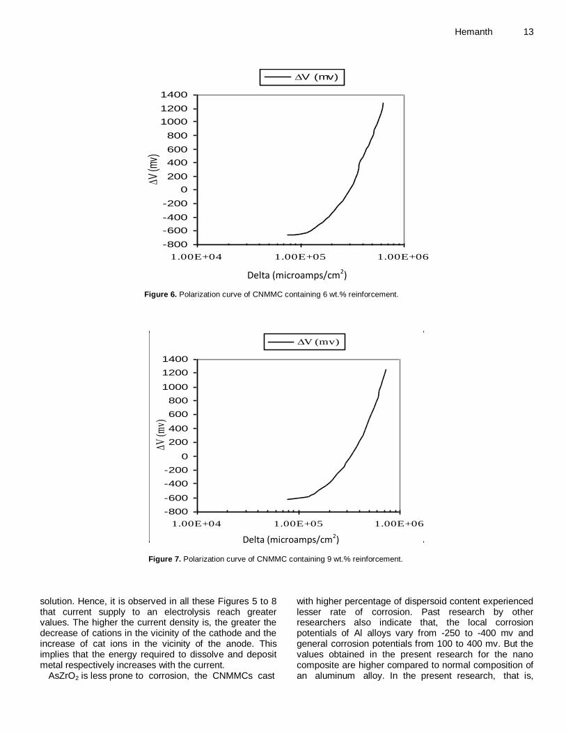
present in CNMMC along with chilling and the ceramic dispersoid (ZrO2), all contribute to superior corrosion resistance. Electrochemical corrosion behaviour of CNMMCs The experimental results of the polarization corrosion test done on different CNMMCs (containing 3, 6, 9 and 12 wt.% dispersoid content) and the resulting polarization curves obtained are shown in Figures 5 to 8, respectively. Figures 5 to 8 indicate that, in every single corrosion test carried out, corrosion rate decreased gradually with time, reaching a stable saturation value after certain duration of testing. This implies that no matter how mild or severe the corrosion was originally, the rate of corrosion will stabilize after a certain time. Nevertheless, even with high dispersoid content, some pitting was detected in the initial stages of most of the tests. Generally, corrosion attack was found to be most severe during the initial stages of the tests but it invariably decreased to a very low value in the later stages, probably due to the formation of an adherent protective layer on the metal surface.
It is well known that polarization is the deviation of the electrochemical process (electrode potential) from the equilibrium due to passing of electric current. In the present investigation too, the values obtained for electrode polarization depends on the difference in the potential difference between the potential of the polarized electrode and that of the electrode in equilibrium with the
Hemanth 13
-800
-600
-400
-200
0
200
400
600
800
1000
1200
1400
1.00E+04 1.00E+05 1.00E+06
Delta(microamps/sqcm)
∆V (m
v)
∆V (mv)
Delta (microamps/cm2) Figure 6. Polarization curve of CNMMC containing 6 wt.% reinforcement.
-800
-600
-400
-200
0
200
400
600
800
1000
1200
1400
1.00E+04 1.00E+05 1.00E+06
Delta(microamps/sqcm)
∆V (m
v)
∆V (mv)
Delta (microamps/cm2)
Figure 7. Polarization curve of CNMMC containing 9 wt.% reinforcement.
solution. Hence, it is observed in all these Figures 5 to 8 that current supply to an electrolysis reach greater values. The higher the current density is, the greater the decrease of cations in the vicinity of the cathode and the increase of cat ions in the vicinity of the anode. This implies that the energy required to dissolve and deposit metal respectively increases with the current.
AsZrO2 is less prone to corrosion, the CNMMCs cast
with higher percentage of dispersoid content experienced lesser rate of corrosion. Past research by other researchers also indicate that, the local corrosion potentials of Al alloys vary from -250 to -400 mv and general corrosion potentials from 100 to 400 mv. But the values obtained in the present research for the nano composite are higher compared to normal composition of an aluminum alloy. In the present research, that is,
14 J. Chem. Eng. Mater. Sci.
-800
-600
-400
-200
0
200
400
600
800
1000
1200
1400
1.00E+04 1.00E+05 1.00E+06
Delta(micrpamps/sqcm)
∆V (m
v)
∆V (mv)
Delta (microamps/cm2)
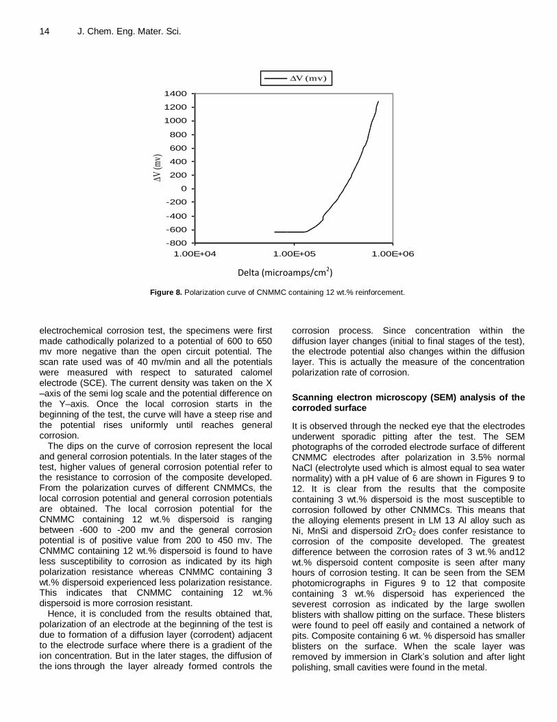
Figure 8. Polarization curve of CNMMC containing 12 wt.% reinforcement.
electrochemical corrosion test, the specimens were first made cathodically polarized to a potential of 600 to 650 mv more negative than the open circuit potential. The scan rate used was of 40 mv/min and all the potentials were measured with respect to saturated calomel electrode (SCE). The current density was taken on the X –axis of the semi log scale and the potential difference on the Y–axis. Once the local corrosion starts in the beginning of the test, the curve will have a steep rise and the potential rises uniformly until reaches general corrosion.
The dips on the curve of corrosion represent the local and general corrosion potentials. In the later stages of the test, higher values of general corrosion potential refer to the resistance to corrosion of the composite developed. From the polarization curves of different CNMMCs, the local corrosion potential and general corrosion potentials are obtained. The local corrosion potential for the CNMMC containing 12 wt.% dispersoid is ranging between -600 to -200 mv and the general corrosion potential is of positive value from 200 to 450 mv. The CNMMC containing 12 wt.% dispersoid is found to have less susceptibility to corrosion as indicated by its high polarization resistance whereas CNMMC containing 3 wt.% dispersoid experienced less polarization resistance. This indicates that CNMMC containing 12 wt.% dispersoid is more corrosion resistant.
Hence, it is concluded from the results obtained that, polarization of an electrode at the beginning of the test is due to formation of a diffusion layer (corrodent) adjacent to the electrode surface where there is a gradient of the ion concentration. But in the later stages, the diffusion of the ions through the layer already formed controls the
corrosion process. Since concentration within the diffusion layer changes (initial to final stages of the test), the electrode potential also changes within the diffusion layer. This is actually the measure of the concentration polarization rate of corrosion.
Scanning electron microscopy (SEM) analysis of the corroded surface
It is observed through the necked eye that the electrodes underwent sporadic pitting after the test. The SEM photographs of the corroded electrode surface of different CNMMC electrodes after polarization in 3.5% normal NaCl (electrolyte used which is almost equal to sea water normality) with a pH value of 6 are shown in Figures 9 to 12. It is clear from the results that the composite containing 3 wt.% dispersoid is the most susceptible to corrosion followed by other CNMMCs. This means that the alloying elements present in LM 13 Al alloy such as Ni, MnSi and dispersoid ZrO2 does confer resistance to corrosion of the composite developed. The greatest difference between the corrosion rates of 3 wt.% and12 wt.% dispersoid content composite is seen after many hours of corrosion testing. It can be seen from the SEM photomicrographs in Figures 9 to 12 that composite containing 3 wt.% dispersoid has experienced the severest corrosion as indicated by the large swollen blisters with shallow pitting on the surface. These blisters were found to peel off easily and contained a network of pits. Composite containing 6 wt. % dispersoid has smaller blisters on the surface. When the scale layer was removed by immersion in Clark’s solution and after light polishing, small cavities were found in the metal.
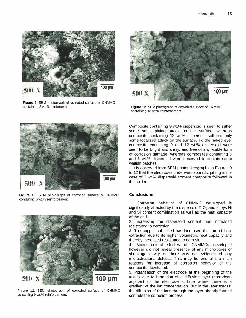
Figure 9. SEM photograph of corroded surface of CNMMC
containing 3 wt.% reinforcement.
Figure 10. SEM photograph of corroded surface of CNMMC
containing 6 wt.% reinforcement.
Figure 11. SEM photograph of corroded surface of CNMMC
containing 9 wt.% reinforcement.
Hemanth 15
Figure 12. SEM photograph of corroded surface of CNMMC containing 12 wt.% reinforcement.
Composite containing 9 wt.% dispersoid is seen to suffer some small pitting attack on the surface, whereas composite containing 12 wt.% dispersoid suffered only some localized attack on the surface. To the naked eye, composite containing 9 and 12 wt.% dispersoid were seen to be bright and shiny, and free of any visible form of corrosion damage, whereas composites containing 3 and 6 wt.% dispersoid were observed to contain some whitish patches.
It is observed from SEM photomicrographs in Figures 9 to 12 that the electrodes underwent sporadic pitting in the case of 3 wt.% dispersoid content composite followed in that order.
Conclusions
1. Corrosion behavior of CNMMC developed is significantly affected by the dispersoid ZrO2 and alloys Ni and Si content combination as well as the heat capacity of the chill. 2. Increasing the dispersoid content has increased resistance to corrosion. 3. The copper chill used has increased the rate of heat extraction due to its higher volumetric heat capacity and thereby increased resistance to corrosion. 4. Microstructural studies of CNMMCs developed however did not reveal presence of any micro-pores or shrinkage cavity or there was no evidence of any microstructural defects. This may be one of the main reasons for increase of corrosion behavior of the composite developed. 5. Polarization of the electrode at the beginning of the test is due to formation of a diffusion layer (corrodent) adjacent to the electrode surface where there is a gradient of the ion concentration. But in the later stages, the diffusion of the ions through the layer already formed controls the corrosion process.

16 J. Chem. Eng. Mater. Sci. 6. Finally, It is observed that no matter how mild or severe the corrosion will be originally, it always settles down to a stable corrosion rate. Conflict of interests The authors have not declared any conflict of interests. REFERENCES Alaneme KK, Ademilua BO, Bodunrim MO (2013). Mechanical
properties and corrosion behaviour of Al reinforced with SiC and bamboo leaf ash. Tribol. Ind. 35:25-35.
Awasthi S, Wood JL (1988). Mechanical properties of extruded ceramic
reinforced Al based composites. Adv. Ceram. Mater. 35:3449-3458. Eckel JF (1956). Stress corrosion cracking of Al alloys in sea water
media. J. Am. Soc. Naval Eng. 78:93-98.
Guy AG (1967). Elements of Physical Metallurgy. Addison-Wesley, USA, 2
nd edition. pp. 78-85.
Hassan SF, Gupta J (2002). Development of high strength Al based
composites using elemental Ni particles. J. Mater. Sci. 137:2467-2477.
Joel H (2003). Effect of high rate heat transfer during casting on the
strength, hardness and wear behavior of Al-Quartz particulate NCMMCs. J. Eng. Manuf. Part-B, Elsevier Sci. 127:651-662.
Joel H (2005). Tribological behavior of cryogenically treated Al-12%Si
alloy/B4C composites. WEAR, Elsevier Sci. 258:1732-1745 Joel H (2007). Cryogenic effects during solidification on the wear
behavior of Al alloy/glass CNMMCs. J. Compos. Mater. Part-A,
Elsevier Sci. 38:1395-1402 Joel H (2008). Production, Mechanical and Thermal properties of chilled
Al-Quartz (SiO2P) castable CNMMC for automotive applications. SAE
International world congress paper. No. 2008-01-1093, Detroit, Michigan, USA.
Joel H (2010). Microstructure, mechanical properties and wear behavior
of metallic, nonmetallic and deep cryogenically chilled ASTM a216 WCB steel. J. Alloys Compds. Elsevier Sci. 506:645-652.
Joel H (2011). Abrasive and slurry wear behaviour of chilled aluminium
alloy (A356) reinforced with fused silica (SiO2P) MMCs. Compos. Part B, Elsevier Sci. 42:1826-1833.
Joel H (2011). Development and wear behaviour of Al/Al2SiO5/C chilled
hybrid metal matrix composites by both experimental and finite element method. SAE International Paper no. 2011-01-0223, PA, USA.
Joel H (2012). Fracture behaviour of cryogenically solidified Al-alloy reinforced with NanoZrO2 MMCs. Int. J. Microstruct. Mater. Properties (IJMMP). Inderscience publication UK. 7(4):617-628.
Lai MO (2000). Development of ductile Mg composite material using Ti
reinforcement. J. Mater. Sci. 38:2155-2167. Lai MO, Saravanaranganathan D (2000). Synthesis, microstructure and
property characterization of disintegrated melt deposited Al/SiC composites. J. Mater. Sci. 35:2155-2164.
Lloyd DJ (1994). Particle reinforced Al-Mg metal matrix composites. Int.
Mater. Rev. 39:1-10. Loganand HL, Mayura GJ (1963). Erosion behaviour of Al alloy
reinforced with Ti particles. Mater. Res. Standard. 3:635-645.
Luo A (1995). Processing, microstructure and mechanical properties of cast Mg CNMMC. Metallurg. Mater. Trans. 26:2445-2453.
Opeka MM, Talmy IG, Zaykoki JA (2004). Mechanical properties of ZrB2
composites. J. Mater. Sci. Elsevier Sc. l 32:5887-5894. Radhakrishna K, Sheshan S (1982). Action of chills on aluminium
alloys. Trans. AFS. 89:158-167
Rajagopal B, Nandan GK (1992). Effect of ceramic reinforcement in Al alloys on corrosion behaviour. Corrosion 48:32-41.
Reddy GP, Paul PK (1976). Action of chills on al-12%Si alloys. Brit.
Foundryman 169:265-272 Ruddle RW (1950). Solidification of Metals. J. Inst. Metals. 77:37-49 Saravananand RA, Surappa MK (2000). Fabrication and
characterization of Al-SiCp particle composite. Mater. Sci. Eng-A276: 108-116.
Shalaby HM, Ikawa HL (1992). Stress corrosion cracking of Al-5% Mg
alloys in sea water Media. Corrosion 48:206-215. Singh A, Tsai AP (2003). Quasicrystal strengthened Mg-Zn-Y alloys by
extrusion. Scripta Materialia, 49:417-426.
Standard A-536-72 Nonferrous castings, Annual Book of ASTM standards (1976). 2:134-145.
Swann PR, Pickering DG (1963). Pit corrosion cracking of Al alloys in
NaCl media. Corrosion 19:369-374. Wang CR, Yang JM (2002). Materials characterization by scanning
electron Microscopy. Mater. Chem. Phys. 14:72-286.
Yamamoto T, Sasamoto H, Inagaki M (2000). Extrusion of Al based composites. J. Mater. Sci. Lett. 19:1053-1064.
Vol. 5(2), pp. 17-32, June 2014
DOI 10.5897/JCEMS2014.0181
Article number:0F8CABD45848
ISSN 2141-6605
Copyright © 2014
Author(s) retain the copyright of this article
http://www.academicjournals.org/JCEMS
Journal of Chemical Engineering and Materials Science
Full Length Research Paper
Utilization of Co-Zeolite imidazolate frameworks (Co-ZIF) as catalyst for organic transformations
Adewale OLAMOYESAN1*, Jiexiang WANG1, Hua ZHANG1, Yu DENG, Bodunde Joseph OWOLABI2 and Binghui CHEN1
1College of Chemistry and Chemical Engineering, National Engineering Laboratory for Green Chemical Productions of
Alcohols–Ethers–Esters, Xiamen University, Xiamen 361005, China. 2Federal University of Technology Akure, P. M. B 704 Akure, Ondo State, Nigeria.
Received 24 April, 2014: Accepted 5 June, 2014.
An excellent conversions of benzaldehyde was obtained under solvent and solvent free conditions by utilizing Co(im)20.5 DMA as catalyst for the synthesis of benzylidene malononitrile. The catalytic prospect of this crystalline porous framework was extended to oxidation reactions involving ethylene glycol (EG) and ethylbenzene (EB). Unexpectedly, EG was totally oxidized to oxalic acid; which demonstrates the catalyst non-selectivity towards glycolic acid. For EB oxidation under a solvent less condition in the presence of oxygen as oxidant (0.8 Mpa), and a 42% conversion was achieved with 78.4% selectivity for acetophenone at 120°C for a period of 2 h. Key words: Metal-organic frameworks, zeolitic imidazolate frameworks, ethylene glycol, ethylbenzene.
INTRODUCTION The next phase after the substantial foundation of metal-organic frameworks (MOFs) synthetic chemistry is the utilization of its chemical versatility and functionality. MOFs have been identified for prospective applications in gas separation and storage, sensors, drug delivery and catalysis (Czaja et al., 2009; Yilmaz et al., 2011; Kuppler et al., 2009; Shekhah et al., 2011). These crystalline frameworks functionalities for catalysis can arise from: metal ions, organic linkers, the pore sites, encapsulated active sites (Corma et al., 2010). The self supporting strategy offers by this class of materials have shown to be effective in a number of different reactions with
various coordination complexes (Corma et al., 2010; Lee et al., 2009; Gascon et al., 2014), and have also provided a desirable environmentally benign and selective catalytic process. MOFs as other heterogeneous catalysts are advantageous for liquid phase organic transformation as they are easily recoverable with minimal environmental impact (Ma and Lin, 2010).
Zeolite imidazolate frameworks (ZIFs), a sub class of this porous material; where its crystal structures share the same topologies as those that can be found in zeolites, were chosen for the catalytic exploration and evaluation on the basis of its thermal and chemical
*Corresponding author. E-mail: [email protected]. Tel: +2348179912978.
Author(s) agree that this article remain permanently open access under the terms of the Creative Commons Attribution
License 4.0 International License

18 J. Chem. Eng. Mater. Sci. stability (Park et al., 2006). Till date, only a few examples of the potential of ZIFs as catalysts have been recently published: ZIF-8 catalyzes the trans-esterification of vegetable oil (Chizallet et al., 2010); and is an active catalyst for the Knoevenagel reaction (Tran et al., 2011); also ZIF-9 has been used as a catalyst in the oxidation of aromatic oxygenates (Zakzeski et al., 2011), and for C-C coupling reaction (Nguyen et al., 2012); ZIF-8 catalyzes the conversion of CO2 to chloropropene carbonate (Miralda et al., 2012) and for synthesis of ethyl methyl carbonate (Zhou et al., 2013); the most recent is Au@ZIF-8 and Au@ZIF-90 for aerobic oxidation of benzyl alcohol (Aijaz and Xu, 2014).
Indeed, in this direction we decide to explore and evaluate the catalytic prospect of Co-ZIFs for; Knoevenagel condensation of benzaldehyde with malononitrile, oxidation of ethylene glycol and ethylbenzene, where the ligand catalyses the condensation and the metal ion (Co
2+) for oxidation
transformation of the substrates of interest. EXPERIMENTAL Materials
Cobalt nitrate hexahydrate (99.50%), Benzaldehyde (98.50%), Malononitrile (99.00%), Ethylene glycol (99.00%), Ethylbenzene (98.50%), N,N-dimethylacetamide (DMA) (99.50%), N,N-dimethylformamide (DMF) (99.50%), Dichloromethane (DCM) (99.50%) and Piperazine (99.00%) were purchased from Sinopharm Chemical Reagent, China. These chemicals were used without further purification.
Preparation of Co-ZIFs
Synthesis of [Co(im)20.5 DMA]∞ (1) Co(Im)20.5 DMA was synthesized based on the procedure reported by Tian et al. (2004) Co(NO3)2.6H2O (3.638 g, 0.0125 mol), C3H4N2 (1.7 g, 0.025 mol), and piperazine (1.075 g, 0.0125 mol) were dissolved in DMA (65 mL). The reaction mixture was stirred at room temperature for 2 h. Then the solution was then placed in a Telfon-lined autoclave and heated in an oven at 135°C and maintained at 135°C for 24 h. After unassisted cooling to room temperature, the violet crystals were collected and washed with DMA (30 mL) with a yield of ~45% based on imidazolate ligand.
Synthesis of Co(im)20.5DMF (2) Co(NO3)26H2O (3.64 g, 0.0125 mol) and C3H4N2(2.35 g, 0.345 mol)
were added to DMF (60 mL). The reaction mixture was stirred at room temperature for 12 h. Then the solution was placed in a Telfon-lined autoclave and heated in an oven at 140°C and maintained at 140°C for 48 h. After unassisted cooling to room temperature, the violet crystals were collected and washed with DMF (30 mL) with a yield of ~25% based on imidazolate ligand.
Synthesis of Co(nim)2 (3)
Co(NO3)26H2O (2.183 g, 7.5 mmol) and 4-nitroimidazole, C3H3N3O2
(8.482 g, 75 mmol) were added to DMF (30 mL). The reaction
mixture was stirred at room temperature for 12 h. Then, the solution was placed in a Telfon-lined autoclave and heated in an oven and maintained at 120°C for 24 h. After cooling to room temperature, the cube-shaped single crystals were collected and washed with DMF (30 mL). Characterization of Co-ZIFs The single crystal data were collected on a Bruker SMART APEX CCD diffractometer with graphite monochromated Mo Kα radiation (λ = 0.71073 Å) radiation. Powder XRD patterns of the samples were recorded on a Phillips X’Pert Pro Super X-ray diffractometer
equipped with X’Celerator detection system and CuKα radiation (40 kV and 30 mA) was used as the X-ray source. Scans were performed over the 2θ range from 5 to 45°, using a resolution of 0.028° in a step size of the 0.0167° and counting of 10 s per step. The morphology of the samples was observed by a field-emission scanning electron microscope (FESEM, LEO-1530, Germany) combined with energy dispersive spectroscopy (EDS) and Olympus optical microscopy. Fourier transform infrared (FT-IR) measurements were recorded on a Nicolet 740 FTIR spectrometer
at ambient conditions. TG–DTA was carried out in static air using a SDT Q600 V20.9 Build 20 thermal analyzer in the temperature range 30 to 800°C at a heating rate of 10°C min
-1. The UV–vis
spectra were recorded on a Shimadzu 1750 UV-vis Spectrophotometer at room temperature. Catalytic activity
Typical procedure for the Knoevenagel condensation reaction Inspired by the principle of green chemistry, the initial reaction was carried out in a solvent free environment and at room temperature. The Knoevenagel reaction between benzaldehyde and malononitrile using Co(im)20.5 DMA as catalyst was carried out in a batch-wise 25-ml round-bottom flask magnetically stirred. A mixture of benzaldehyde (5.16 ml, 0.05 mol), and malononitrile (3.03 g, 0.05
mol) was placed into the flask and stirred for 2 min; thereafter 0.295 g, 5 mmol of catalyst was added to the reaction mixture. The catalyst concentration was calculated with respect to the cobalt/benzaldehyde molar ratio. The reaction vessel was continuously stirred until the completion of the reaction, where the porous crystal solid absorbed all the solvent and formed a sticky amorphous brown gel after 5 min. After the completion of the reaction, the product was obtained with the addition of 10 ml DCM, and then the solid cobalt imidazolate framework was separated from the mixture by simple centrifugation and then followed by filtration when necessary; for reusability sake, the catalyst was washed with copious amount of DCM dried under vacuum at 60°C for 12 h. The reaction mixture was analyzed by Shimadzu GC 2010, filtered through a short silica gel pad, analyzed by GC and the product identity was confirmed by GC-MS when necessary.
Gas chromatographic (GC) analyses were performed using a Shimadzu GC 2010 equipped with a flame ionization detector (FID) and a DB-35 column (length = 60 m, inner diameter = 0.25 mm, and film thickness = 0.25 μm). The temperature program for GC analysis was kept at 70°C for 6 min and heated samples from 70 to 280°C at 5°C
/min and were held at 280°C for 15 min. Injector and
detector temperatures were set constant at 280°C with a column flow rate of 2.0 m/L
-1.
Typical procedure for the oxidation of ethylene glycol
The investigation of possible oxidation of ethylene glycol into less toxic or useful products such as glycolic acid was carried out in a

OLAMOYESAN et al. 19
10 20 30
Simulated Co(Im)20.5DMA
As-synthesized Co(Im)20.5DMA
Inte
nsi
ty
2(degrees)
Figure 1. Comparison of the experimental PXRD of as-synthesized Co(im)20.5DMA with the simulated pattern from its single crystal structure.
300 ml Parr reactor (550 series). Ethylene glycol, NaOH (50 mmol) and the catalyst (metal/reactant = 10
-3) were mixed with distilled
water to a total volume of 100 ml. The reaction mixture was charged into the autoclave, exchanged three times with pure oxygen, pressurized with O2 to 300 KPa, and then stirred and heated to appropriate temperature. After the reaction mixture was cooled to room temperature, the excess gas was vented, the resultant liquid
was taken out and the catalyst was separated from the mixture by simple filtration. The aqueous solution was analyzed by a Dionex Ultimate U3000 HPLC system, equipped with online degasser, dual gradient pump (loading pump and analytical pump), an auto sampler with a 100 μL sample loop, a column oven, and a diode array detector. The Chroméléon software (Dionex, Sunnyvale, USA) was used to control the system to collect data. A reversed phase column of Acclaim ® Polar Advantage II (PA II) C18 (150 mm × 4.6 mm, 5 μm) was used with aqueous 0.01 M H2SO4 (0.8
ml/min) as the eluent. Samples of reaction mixture (0.1 ml) were diluted (10 ml) by using the eluent. Typical procedure for the oxidation of ethylbenzene
The heterogeneous catalytic oxidation reaction was performed in 100 ml stainless steel reactor. Ethylbenzene (98.50%) was used as
obtained without any further purification, and the asynthesized catalyst with DMA guest molecule was exchanged by dichloromethane (DCM) (3 × 15 ml) for 3 days; thereafter the residual solvents were removed under vacuum at 200°C for 6 h. In a typical experimental procedure, ethylbenzene (30 ml, 0.4 mol) and cobalt imidazolate framework Co(im)2.0.5 DMA (0.928 g, 0.04 mol) were added into the 100 ml autoclave, exchanged three times with pure oxygen, filled with O2 to 0.8×10
6 Pa, stirred and heated to
120°C for a period of 2 h. After the reaction mixture was cooled to room temperature in a bath of ice/water mixture, excess gas was vented, resultant liquid was taken out and solid catalyst was separated from the mixture by simple centrifugation followed
by filtration when necessary; for reusability sake the catalyst was washed with copious amount of DCM dried under vacuum at 60°C for 12 h.
The filtrate was analyzed with Shimadzu GC 2010, filtered through a short silica gel pad and the product identity was confirmed by Gas chromatography–mass spectrometry (GC-MS). Gas chromatographic (GC) analyses were performed using a
Shimadzu GC 2010 equipped with a flame ionization detector (FID) and a AT-SE 30 column (length = 30 m, inner diameter = 0.25 mm, film thickness = 0.33 μm). The temperature program for GC analysis started from 40 to 200°C at 10°C/min, kept at 200°C for 10 min, heated from 200 to 280°C and held at 280°C for 2 min. Injector and detector temperatures were set constant at 200 and 280°C, respectively with a column flow rate 2.0 ml
-1.
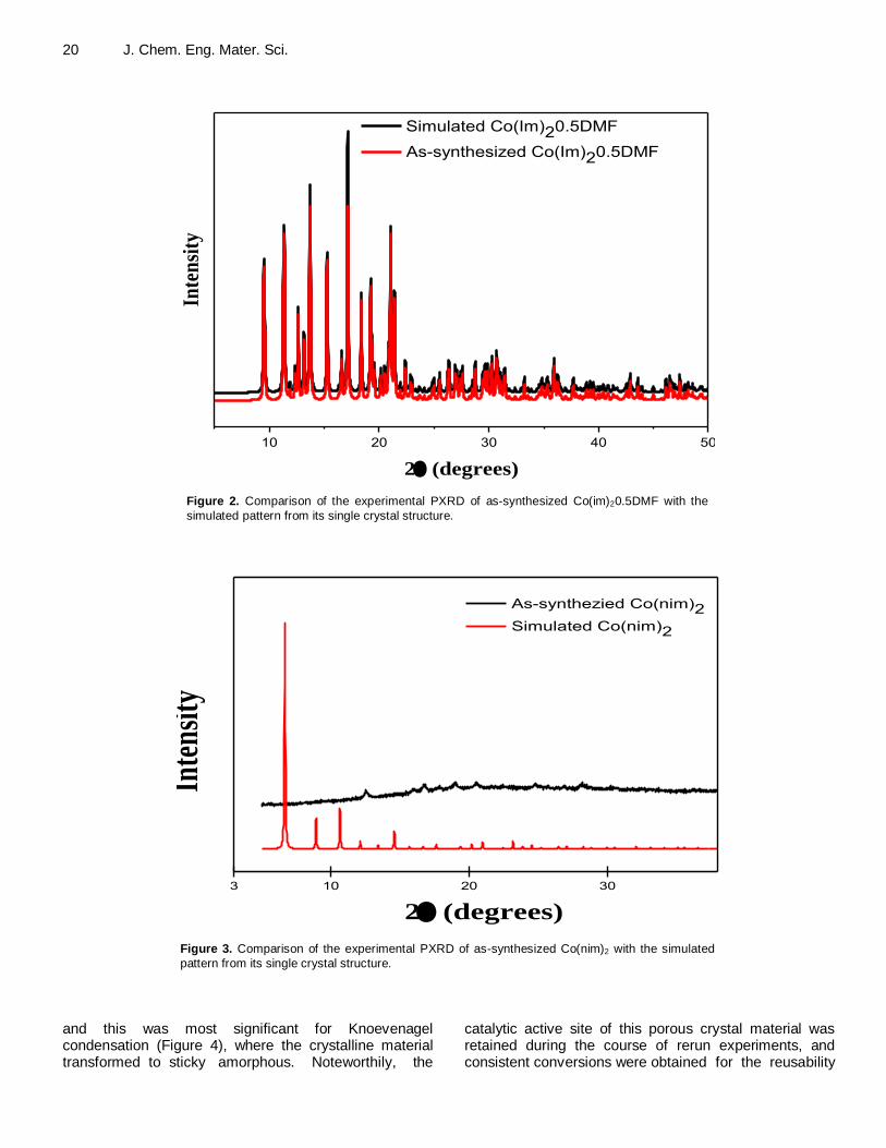
RESULTS AND DISCUSSION Characterization of the catalysts There exist high degrees of correspondence between the experimental and simulated XRD patterns for both Co(im)20.5 DMA and Co(im)20.5DMF as shown in (Figures 1 and 2); which is an indication that the bulk material is a true representation of the single crystal. On the other hands, the powder pattern simulated Co(nim)2 revealed three clearly observable peaks and several weak reflections in the range of 2θ (12 to 40°), which are not visible on the experimental pattern (Figure 3). The observed difference in diffractograms could be attributed to the preferred orientation of growth during Co(nim)2 synthesis. An apparent decline in the intensity of the peaks were observed for used Co(im)20.5 DMA catalyst
20 J. Chem. Eng. Mater. Sci.
10 20 30 40 50
Inte
nsi
ty
2 (degrees)
Simulated Co(Im)20.5DMF
As-synthesized Co(Im)20.5DMF
Figure 2. Comparison of the experimental PXRD of as-synthesized Co(im)20.5DMF with the
simulated pattern from its single crystal structure.
3 10 20 30
As-synthezied Co(nim)2
Simulated Co(nim)2
Inte
nsit
y
2 (degrees)
Figure 3. Comparison of the experimental PXRD of as-synthesized Co(nim)2 with the simulated
pattern from its single crystal structure.
and this was most significant for Knoevenagel condensation (Figure 4), where the crystalline material transformed to sticky amorphous. Noteworthily, the
catalytic active site of this porous crystal material was retained during the course of rerun experiments, and consistent conversions were obtained for the reusability

Olamoyesan et al. 21
10 20 30 40
As-synthesized Co(im)20.5DMA
After Oxidation of Ethylene Glycol
After Oxidation of Ethylbenzene
After Knoevenagel CondensationIn
tens
ity
2 (degrees)
Figure 4. Comparison of PXRD pattern of fresh Co(im)20.5DMA and after usage for specific
organic synthesis reaction.
10 20 30 40
As-synthezied Co(nim)2
After Knoevenagel Condensation
Inte
nsity
2 (degrees)
Figure 5. Comparison of PXRD pattern of fresh Co(nim)2 and after usage for specific organic
synthesis reaction.
test. For Co(nim)2 diffraction patterns (Figure 5), the peaks of the used catalysts were maintained as fresh material, which demonstrates the stability of Co(nim)2 after usage as catalyst for Knoevenagel condensation.
Scanning electron microscope (SEM) shows a highly crystalline dipyramid (Figure 6a) and rhombic prism
(Figure 6b) shape crystals which confirmed the aforementioned crystal system specified by the Single Crystal X-ray analysis with a crystal sizes ranging approximately between 100 and 200 μm. Also, the optical micrograms confirmed the shape of the crystalline frameworks (Figure A in Supporting Appendix) which are

22 J. Chem. Eng. Mater. Sci.
Fig. 6. SEM micrograms of (a) Co(im)20.5DMA and (b) Co(im)20.5DMF.
(a)
(b)
Figure 6. SEM micrograms of (a) Co(im)20.5DMA and (b) Co(im)20.5DMF.
in agreement with previous reports on cobalt imidazolate frameworks (Tian et al., 2004; Banerjee et al., 2008).
Thermogravimetric analysis (TGA) shows weight loss of 8% up to 200°C corresponds to the release of guest molecules (0.5 DMA), and the most noteworthy feature in this result was found between the temperature range of
200 to 340°C with little weight loss, indicating that the Co(im)20.5 DMA was stable up to 340°C (Figure 7). Afterward, a very rapid weight-loss step of 54% was observed as the temperature increased from 340 to 430°C demonstrating the thermal decomposition of the Co(im)20.5 DMA.

Olamoyesan et al. 23
0 100 200 300 400 500 600 700 800 900
0.3
0.4
0.5
0.6
0.7
0.8
0.9
1.0
Wei
gh
t lo
ss
Temperature (oC)
-100
-50
0
50
100
150
200
250
Hea
t fl
ow
-0.20
-0.15
-0.10
-0.05
0.00
Wei
gh
t
Fig. 6. SEM micrograms of (a) Co(im)20.5DMA and (b) Co(im)20.5DMF.
Temperature (°C)
Figure 7. Thermogravimetric analysis (TGA) analysis of the Co(im)20.5DMA.
Fig.8. FT-IR spectra of (a) Co(im)2.0.5DMA and (b) imidazole.
Wave number (cm-1)
(a)
(b)
Figure 8. FT-IR spectra of (a) Co(im)2.0.5DMA and (b) Imidazole.
Fourier transform infrared (FT-IR) spectra of Co(im)20.5 DMA alongside that of imidazole are shown in Figure 8. The presence of strong and broad N–H--N hydrogen bond was observed in the FT-IR spectra of imidazole ranging from 3350 to 2200 cm
-1 with a maximum at about
2613 cm-1
and associated with weak band near 1830 cm-
1; while the observed disappearance of these absorption
bands evidently indicates the deprotonation of the
imidazole ligands during the formation of this porous crystalline framework (Corma et al., 2010). Besides, stretching vibrations of C-H bonds was observed near 3125 cm
-1 and the double bond in the imidazole ring
absorbs at 1650 cm-1
. Figure B1 in Supporting Appendix shows the FT-IR spectra of fresh Co(im)20.5 DMA along with used catalyst after specific organic transformation. In addition, the spectra for nitroimidazole along with fresh
24 J. Chem. Eng. Mater. Sci.
400 500 600 700 800 900
0.2
0.3
0.4
0.5
0.6
0.7
0.8
Complex solutionA
bso
rban
ce
Wave length / nm
Intact crystal
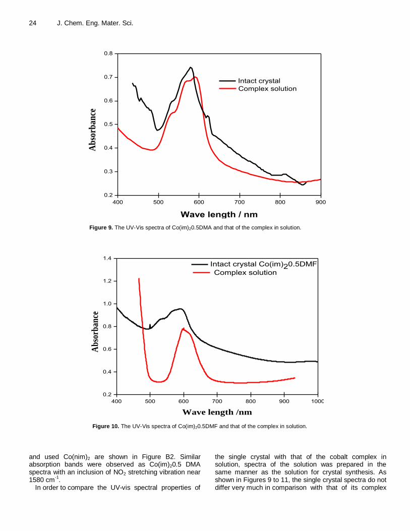
Figure 9. The UV-Vis spectra of Co(im)20.5DMA and that of the complex in solution.
400 500 600 700 800 900 1000
0.2
0.4
0.6
0.8
1.0
1.2
1.4
Intact crystal Co(im)20.5DMF
Ab
sorb
ance
Wave length /nm
Complex solution
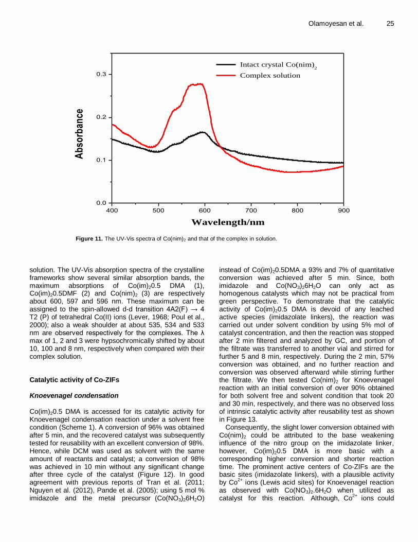
Figure 10. The UV-Vis spectra of Co(im)20.5DMF and that of the complex in solution.
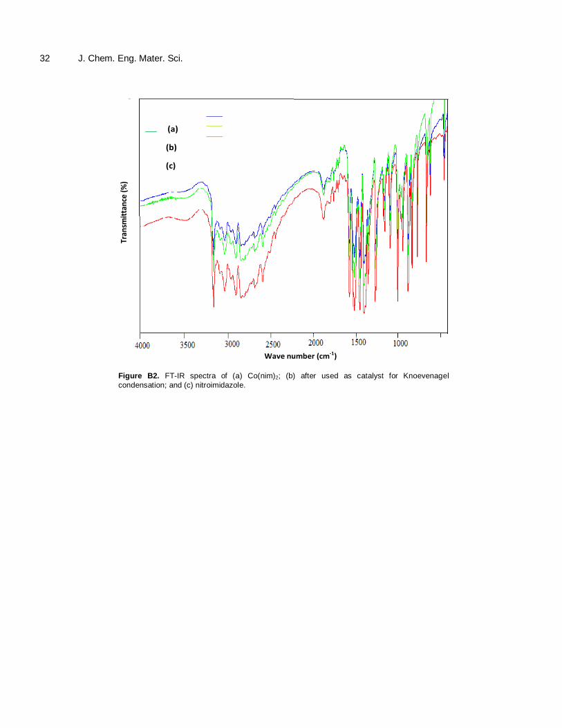
and used Co(nim)2 are shown in Figure B2. Similar absorption bands were observed as Co(im)20.5 DMA spectra with an inclusion of NO2 stretching vibration near 1580 cm
-1.
In order to compare the UV-vis spectral properties of
the single crystal with that of the cobalt complex in solution, spectra of the solution was prepared in the same manner as the solution for crystal synthesis. As shown in Figures 9 to 11, the single crystal spectra do not differ very much in comparison with that of its complex
Olamoyesan et al. 25
400 500 600 700 800 900
0.0
0.1
0.2
0.3A
bso
rban
ce
Wavelength/nm
Intact crystal Co(nim)2
Complex solution
Figure 11. The UV-Vis spectra of Co(nim)2 and that of the complex in solution.
solution. The UV-Vis absorption spectra of the crystalline frameworks show several similar absorption bands, the maximum absorptions of Co(im)20.5 DMA (1), Co(im)20.5DMF (2) and Co(nim)2 (3) are respectively about 600, 597 and 596 nm. These maximum can be assigned to the spin-allowed d-d transition 4A2(F) → 4 T2 (P) of tetrahedral Co(II) ions (Lever, 1968; Poul et al., 2000);
also a weak shoulder at about 535, 534 and 533
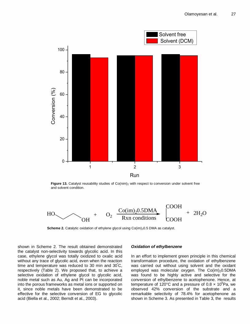
nm are observed respectively for the complexes. The λ max of 1, 2 and 3 were hypsochromically shifted by about 10, 100 and 8 nm, respectively when compared with their complex solution. Catalytic activity of Co-ZIFs Knoevenagel condensation Co(im)20.5 DMA is accessed for its catalytic activity for Knoevenagel condensation reaction under a solvent free condition (Scheme 1). A conversion of 96% was obtained after 5 min, and the recovered catalyst was subsequently tested for reusability with an excellent conversion of 98%. Hence, while DCM was used as solvent with the same amount of reactants and catalyst; a conversion of 98% was achieved in 10 min without any significant change after three cycle of the catalyst (Figure 12). In good agreement with previous reports of Tran et al. (2011; Nguyen et al. (2012), Pande et al. (2005); using 5 mol % imidazole and the metal precursor (Co(NO3)26H2O)
instead of Co(im)20.5DMA a 93% and 7% of quantitative conversion was achieved after 5 min. Since, both imidazole and Co(NO3)26H2O can only act as homogenous catalysts which may not be practical from green perspective. To demonstrate that the catalytic activity of Co(im)20.5 DMA is devoid of any leached active species (imidazolate linkers), the reaction was carried out under solvent condition by using 5% mol of catalyst concentration, and then the reaction was stopped after 2 min filtered and analyzed by GC, and portion of the filtrate was transferred to another vial and stirred for further 5 and 8 min, respectively. During the 2 min, 57% conversion was obtained, and no further reaction and conversion was observed afterward while stirring further the filtrate. We then tested Co(nim)2 for Knoevenagel reaction with an initial conversion of over 90% obtained for both solvent free and solvent condition that took 20 and 30 min, respectively, and there was no observed loss of intrinsic catalytic activity after reusability test as shown in Figure 13.
Consequently, the slight lower conversion obtained with Co(nim)2 could be attributed to the base weakening influence of the nitro group on the imidazolate linker, however, Co(im)20.5 DMA is more basic with a corresponding higher conversion and shorter reaction time. The prominent active centers of Co-ZIFs are the basic sites (imidazolate linkers), with a plausible activity by Co
2+ ions (Lewis acid sites) for Knoevenagel reaction
as observed with Co(NO3)2.6H2O when utilized as catalyst for this reaction. Although, Co
2+ ions could

26 J. Chem. Eng. Mater. Sci.
CHO
+
CN
CN
Co(Im)2.0.5DMA
room temp;solvent free+ H2O
CN
CN
Scheme 1. Knoevenagel reaction of benzaldehyde with malononitrile using [Co(im)20.5 DMA]∞ as catalyst.
96 98 9898 98 97
1 2 3
0
20
40
60
80
100
Co
nve
rsio
n (
%)
Run
Solvent free
Solvent (DCM)
Figure 12. Catalyst reusability studies of Co(im)20.5 DMA with respect to conversion under
solvent free and solvent condition.
activate the carbonyl substrates of the Knoevenagel condensation acting as catalyst or co-catalyst for the reaction (Gascon et al., 2009; Llabrés et al., 2012); markedly, the extra frameworks of CoO (impurities entrapped inside the pore cavities as either nanoparticles or segregated crystallites) also contribute to the catalytic activities of CO-ZIFs (Llabrés et al., 2012; Hafizovic et al., 2007; Calleja et al., 2010; Neogi et al., 2009). Comparative studies of the catalytic behaviour of Co-ZIFs
with other state-of-the-art catalysts for the Knoevenagel condensation are shown in Table 1. We found that Co-ZIFs are efficient in the Knoevenagel condensation for the synthesis of benzylidene malononitrile. The conversions obtained with Co-ZIFs are higher than some previously obtained with Co-ZIFs; are higher than some previously
reported catalysts, where higher active methylene compounds moles were required for the same reaction and longer reaction time. Conversely, our catalysts exhibited less activity in the Knoevenagel condensation as compared to some base catalysts such as functionalized cobalt spinel ferrite and amine functionalized mesoporous zirconia (Tran et al., 2011; Phan and Jones, 2006; Parida et al., 2010).
Oxidation of ethylene glycol
In an effort to transform ethylene glycol to glycolic acid the catalytic prospect of this material was explored as
Olamoyesan et al. 27
1 2 3
0
20
40
60
80
100C
on
ve
rsio
n (
%)
Run
Solvent free
Solvent (DCM)
Figure 13. Catalyst reusability studies of Co(nim)2 with respect to conversion under solvent free
and solvent condition.
HOOH
+ O2
Co(im)20.5DMA
Rxn conditions
COOH
COOH
+ 2H2O
Scheme 2. Catalytic oxidation of ethylene glycol using Co(im)20.5 DMA as catalyst.
shown in Scheme 2. The result obtained demonstrated the catalyst non-selectivity towards glycolic acid. In this case, ethylene glycol was totally oxidized to oxalic acid without any trace of glycolic acid, even when the reaction time and temperature was reduced to 30 min and 30
ºC,
respectively (Table 2). We proposed that, to achieve a selective oxidation of ethylene glycol to glycolic acid, noble metal such as Au, Ag and Pt can be incorporated into the porous frameworks as metal ions or supported on it, since noble metals have been demonstrated to be effective for the selective conversion of EG to glycolic acid (Biella et al., 2002; Berndt et al., 2003).
Oxidation of ethylbenzene In an effort to implement green principle in this chemical transformation procedure, the oxidation of ethylbenzene was carried out without using solvent and the oxidant employed was molecular oxygen. The Co(im)20.5DMA was found to be highly active and selective for the conversion of ethylbenzene to acetophenone. Hence, at temperature of 120°C and a pressure of 0.8 × 10
6Pa, we
observed 42% conversion of the substrate and a remarkable selectivity of 78.4% for acetophenone as shown in Scheme 3. As presented in Table 3, the results

28 J. Chem. Eng. Mater. Sci. Table 1. Comparative studies of the catalytic behaviour of Co(im)20.5 DMA) with other catalysts for Knoevenagel condensation.
Catalyst Reaction conditions Time (min) Conversion/Yield Reference
Diaminosilane-functionalized cobalt spinel ferrite (CoFe2O4)
2.5 mol % of catalyst; Solvent: benzene; and at room temp; reactants mole ratio: malononitrile/benzaldehyde 2:1
5 100 Phan and Jones (2006)
ZIF-8 5 mol % catalyst, Solvent: Toluene; and at room temp; reactants mole ratio: malononitrile/benzaldehyde 4:1
120 100 Tran et al. (2011)
amine-functionalized mesoporous zirconia
1.79 mol % catalyst; Methanol; reactant mole ratio: and at room temp benzaldehyde/malonic ester1:1
1440 89 Parida et al. (2010)
Guanidium lactate ionic liquid 2.5 mmol IL; and at room temp; reactants mole ratio: malononitrile/benzaldehyde 1:1
2 93a Xin et al. (2007)
In/AlMCM-41 0.06 mol % of In/AlMCM-41; under reflux condition in ethanol; reactants mole ratio: malononitrile/benzaldehyde 1.2:1
25 95a Katkar et al. (2010)
Co(im)20.5DMA 10 mol % Catalyst; and at room temp; reactants mole ratio: malononitrile/benzaldehyde 1:1
5 98 This study
Co(nim)2 10 mol % Catalyst; and at room temp; reactants mole ratio: malononitrile/benzaldehyde 1:1
20 96 This study
a is product yield; T is this study, IL is ionic liquid.
for optimized reaction process for ethylbenzene oxidation are summarized. The conversion of ethylbenzene and its selectivity towards acetophenone increased rapidly from42 to 71.3%, as temperature increased from 120 to 150°C. When the reaction time was increased from 2 to 10 h, initially both the conversion and selectivity of acetophonene increased and afterward no obvious change was observed due to inhibition by the product, while as a result of over oxidation of acetophenone or methylbezylalcohol to benzoic acid the selectivity decreased gradually from 87.3 to 80.5%. As the pressure increased from 0.8 to 2.0 MPa, the conversion of the substrate and selectivity to acetophenone increased as well.
Likewise, the effect of catalyst concentration was studied, as the concentration Co-ZIF increased
from 0.04 to 0.2 mol, the conversion of substrate rapidly increased from 42 to 71.2% and acetophenone selectivity increased from 78.4 to 84.5%. Furthermore, the investigation of Co(nim)2 and Co(NO3)2.6H2O for catalytic oxidation of substrate under similar experimental condition, it was found that 40.3 and 39.4% of the ethylbenezene was converted to main product respectively, and a reasonable selectivity was obtained for both the crystalline porous framework and cobalt precursor. Conclusion We examined Knoevenagel condensation of benzaldehyde using Co-ZIFs as catalyst for the
synthesis of benzylidene malononitrile under a solvent and solvent less condition with a remarkable conversion. The Co
2+ of the
coordination complex was explored for oxidation of ethylbenzene and ethylene glycol, since cobalt metal precursor was an important catalyst for oxidation transformation. As a result, the crystalline framework was not selective towards glycolic acid but oxidized the substrate to oxalic is less toxic. Moreover, Co-ZIF was found to be highly active for the oxidation of ethylbenzene and remarkably selective for acetophenone. This work accentuates the usefulness of MOFs as heterogeneous catalysts for organic synthesis, where either the metal ions or ligands can serve as catalyst for different organic transformations of interest.

Olamoyesan et al. 29
Table 2. Catalytic oxidation of ethylene glycol using Co-ZIF as heterogeneous catalyst.
Catalyst (DMA) Temp (°C) Time (h) Yield (%)
Co(im)20.5 70 6 85
Co(im)20.5 30 3 65
Co(im)20.5 30 1! 17
Co(im)20.5 30 0.5 6.5
DMA is N,N-dimethylacetamide; reaction mixture with NaOH.
CH3CH3 CHOCOCH3
Ethylbenzene BenzaldehydeAcetophenone
CH2OH COOH
++ +
Benzoic acidα-methylbenzyl alcohol
O
Co-ZIF
Scheme 3. Result of oxidation of ethylbenzene using Co(im)20.5 DMA as catalyst.
Table 3. Catalytic oxidation of ethylbenzene under solvent less condition using Co-ZIFs as heterogeneous catalyst.
S/N Reaction conditions Conv (%) Selectivity (%)
I II III IV
1 120°C 42 78.4 15.5 0.7 5.4
2 130°C 57.5 79.5 13.8 0.6 6.1
3 140°C 67.8 83.6 12.1 0.7 3.6
4 150°C 71.3 84.5 7.8 0.5 7.2
5 4 h 70.4 87.3 6.1 0.6 6.0
6 6 h 70.8 86.5 5.7 0.5 7.3
7 8 h 71.3 81.4 4.9 0.4 13.3
8 10 h 71.5 80.5 4.1 0.4 15.0
9 1.5 Mpa 60.5 85.7 6.3 0.7 7.3
10 2.0 Mpa 67.4 87.8 5.4 0.5 6.3
11 0.08 mol 54.3 83.5 4.3 1.2 11
12 0.12 mol 59.5 83.9 4.5 0.8 10.8
13 0.16 mol 65.4 86.8 3.9 0.3 9
14 0.2 mol 71.2 84.5 3.1 0.3 12.1
15 Co(nim)2 40.3 78.7 15.1 0.6 5.6
16 Co(OAC)2.6H20 39.4 69.1 18.3 2.4 10.2
ACKNOWLEDGEMENTS
We are grateful to the Chinese Government Scholarship Council and Xiamen University for providing necessary support during the course of this research. We also acknowledge one of the reviewers for helpful suggestions and comments.
Conflict of interests
The authors have not declared any conflict of interests.
REFERENCES
Aijaz A, Xu Q (2014). Catalysis with Metal Nanoparticles Immobilized
within the Pores of Metal–Organic Frameworks. J. Phys. Chem. Lett.
5(8):1400-1411.
Banerjee R, Phan A, Wang B, Knobler C, Furukawa H, O'Keeffe M, Yaghi OM (2008). High-Throughput Synthesis of Zeolitic Imidazolate
Frameworks and Application to CO2 Capture. Sci. 319(5865):939-943.
Berndt H, Pitsch I, Evert S, Struve K, Pohl MM, Radnik J, Martin A
(2003). Oxygen Adsorption on Au/Al2O3 Catalysts and Relation to the Catalytic Oxidation of Ethylene Glycol to Glycolic Acid. Appl. Catal. A. 244(1):169-179.
Biella S, Castiglionib GL, Fumagallib C, Pratia L, Rossi M (2002). Application of Gold Catalysts to Selective Liquid Phase Oxidation. Catal. Today 72(1-2):43-49.
30 J. Chem. Eng. Mater. Sci. Calleja G, Botas JA,Orcajo MG,Sánchez-Sánchez M (2010).
Differences between the isostructural IRMOF-1 and MOCP-L porous adsorbents. J. Porous Mater. 17:91-97.
Chizallet C, Lazare S, Bazer-Bachi D, Bonnier F, Lecocq V, Soyer E, Quoineaud AA, Bats N (2010). Catalysis of Transesterification by a Nonfunctionalized Metal-Organic Framework: Acido-Basicity at the
External surface of ZIF-8 Probed by FTIR and ab Initio Calculations. J. Am. Chem. Soc. 132(35):12365-12377.
Corma A, Garcı´a H, Llabrés FX, Xamena I (2010). Engineering Metal
Organic Frameworks for Heterogeneous Catalysis. Chem. Rev. 110(8):4606-4655.
Czaja AU, Trukhan N, Müller U (2009). Industrial Applications of Metal–
Organic Frameworks. Chem. Soc. Rev. 38:1284-1293. Gascon J, Aktay U, Hernandez-Alonso MD, van Klink GPM, Kapteijn F
(2009). Amino-based metal-organic frameworks as stable, highly
active basic catalysts J. Catal. 261(1):75-87. Gascon J, Corma A, Kapteijn F, Llabrés FX, Xamena I (2014). Metal
Organic Framework, Catalysis: Quo vadis? ACS Catal. 4(2):361-378.
Hafizovic J, Bjorgen M, Olsbye U, Dietzel PDC, Bordiga S, Prestipino C, Lamberti C, Lillerud KP (2007). The Inconsistency in Adsorption Properties and Powder XRD Data of MOF-5 Is Rationalized by
Framework Interpenetration and the Presence of Organic and Inorganic Species in the Nanocavities. J. Am. Chem. Soc. 129(12):3612–3620.
Kuppler RJ, Timmons DJ, Fang QR, Li JR, Makal TA, Young MD, Yuan D, Zhao D, Zhuang W, Zhou HC (2009). Potential Applications of Metal-Organic Frameworks. Coord. Chem. Rev. 253(23-24):3042-
3066. Lee J, Farha OK, Roberts J, Scheidt KA, Nguyen ST, Hupp JT (2009).
Metal-Organic Framework Materials as Catalysts. Chem. Soc. Rev.
38:1450-1459. Lever ABP (1984). Inorganic Electronic Spectroscopy. Elsevier,
Amsterdam.
Llabrés FX Xamena I, Cirujano FG, Corma A (2012). An unexpected bifunctional acid base catalysis in IRMOF-3 for Knoevenagel condensation reactions. Micro. Meso. Mater. 157:112–117.
Ma L, Lin W (2010). Designing metal-organic frameworks for catalytic applications. Top Curr. Chem. 293:175-205.
Miralda CM, Macias EE, Zhu M, Ratnasamy P, Carreon MA (2012).
Zeolitic Imidazole Framework-8 Catalysts in the Conversion of CO2 to Chloropropene Carbonate, ACS Catal. 2(1):180-183.
NguyenLTL, Le KKA, Truong HX, Phan NTS (2012). MetalOrganic
Frameworks for Catalysis: The Knoevenagel Reaction Using Zeolite Imidazolate Framework ZIF-9 as an Efficient Heterogeneous catalyst. Catal. Sci. Technol. 2:521-528.
Neogi S, Sharma MK, Bharadwaj PK (2009). Knoevenagel
condensation and cyanosilylation reactions catalyzed by a MOF containing coordinatively unsaturated Zn(II) centers. J. Mol. Catal. A: Chem. 299(1-2):1-4.
Pande A, Ganesan K, Jain AK, Gupta PK, Malhotra RC (2005). A Novel Eco-Friendly Process for the Synthesis of 2-Chlorobenzylidenemalononitrile and its Analogues Using Water As a
Solvent, Org. Process Res. Dev. 9(2):133-136. Parida KM, Mallick S, Sahoo PC, Rana SK, Facile A (2010). Method for
Synthesis of Amine-Functionalized Mesoporous Zirconia and its
Catalytic Evaluation in Knoevenagel Condensation. Appl. Catal. A. 381(1-2):226-232.
Park KS, Ni Z, Cote AP, Choi JY, Huang R, Uribe-Romo FJ, Chae HK,
O'Keeffe M, Yaghi OM (2006). Exceptional Chemical and Thermal Stability of Zeolitic Imidazolate Frameworks. Proc. Natl. Acad. Sci. USA 103(27):10186-10191.
Phan NTS, Jones CW (2006). Highly Accessible Catalytic Sites on
Recyclable Organosilane-Functionalized Magnetic Nanoparticles: An Alternative to Functionalized Porous Silica Catalysts. J. Mol. Catal. A:
Chem. 253(1-2):123-131. Poul L, Jouini N, Fiévet F (2000). Layered Hydroxide Metal Acetates
(Metal = Zinc, Cobalt, and Nickel): Elaboration via Hydrolysis in
Polyol Medium and Comparative Study. Chem. Mater. 12(10):3123-3132.
Santosh SK, Machhindra KL, Balasaheb RA, Sandip BR (2010). Indium
Modified Mesoporous Zeolite AlMCM-41 as a Heterogeneous Catalyst for the Knoevenagel Condensation Reaction. Bull. Korean Chem. Soc. 31(5):1301-1304.
Shekhah O, Liu J, Fischer RA, Wöll CH (2011). Mof Thin Films: Existing and Future Applications. Chem. Soc. Rev. 40:1081-1106.
Tian YQ, Chen ZX, Weng LH, Guo HB, Gao S, Zhao DY (2014). Two
Polymorphs of Cobalt(II) Imidazolate Polymers Synthesized Solvothermally by Using One Organic Template N,N-Dimethylacetamide, Inorg. Chem. 43(15):4631-4635.
Tran UPN, Le KKA, Phan NTS (2011). Expanding Applications of Metal−Organic Frameworks: Zeolite Imidazolate Framework ZIF-8 as an Efficient Heterogeneous Catalyst for the Knoevenagel Reaction.
ACS Catal. 1(2):120-127. Xin X, Guo X, Duan H, Lin Y, Sun H (2007). Efficient Knoevenagel
Condensation Catalyzed by Cyclic Guanidinium Lactate Ionic Liquid
as Medium. Catal. Commun. 8(2):115-117. Yilmaz B, Trukhan N, Müller U (2011). Industrial Outlook on Zeolites
and Metal Organic Frameworks. Chin. J. Catal. 33(1):3-10.
Zakzeski J, Dębczak A, Bruijnincx PCA, Weckhuysen BM (2011). Catalytic Oxidation of Aromatic Oxygenates by the Heterogeneous Catalyst Co-ZIF-9. Appl. Catal. A. 394(1-2):79-85.
Zhou X, Zhang HP, Wang GY, Yao ZG, Tang YR, Zheng SS (2013). Zeolitic imidazolate framework as efficient heterogeneous catalyst for the synthesis of ethyl methyl carbonate. J. Mol. Catal. A: Chem. 366:43-47.

Olamoyesan et al. 31 APPENDIX
Supporting Appendix
Fig. A: Optical micrograms of (a) Co(im)20.5DMA; (b) Co(im)20.5DMF and (c-d) Co(nim)2 .
Figure A. Optical micrograms of (a) Co(im)20.5DMA; (b) Co(im)20.5DMF and (c-d) Co(nim)2 .
(a)
(b)
(c)
(d)
Wave number (cm-1)
Tran
smit
tan
ce (
%)
Figure. B1. FT-IR spectra of (a) fresh Co(im)20.5DMA ; after used for (b) Knoevenagel
condensation (c) oxidation of Ethybenzene and (d) ethylene glycol.
32 J. Chem. Eng. Mater. Sci.
(a)
(b)
(c)
Tran
smit
tan
ce (
%)
Wave number (cm-1)
Figure B2. FT-IR spectra of (a) Co(nim)2; (b) after used as catalyst for Knoevenagel
condensation; and (c) nitroimidazole.