31
CIDM-E CIDM-I P/N IGIC-CIDM-0909 INSTALLATION & OPERATION GUIDE /CHINO CIDM (-E, -I) REV. 0909 Installation & Operation Manual

CIDM-ECIDM-I
p/n IGIC-CIDM-0909
INSTALLATION & OPERATION GUIDE
/CH
INO
CID
M (-
E, -
I)
Rev.
090
9
Inst
alla
tion
&
Ope
ratio
n
Man
ual

IGIC-CIDM-0909
�
/CHINOA publication of HUSSMANN® Chino 13770 Ramona Avenue • Chino, California 91710(909) 6�8-894� FAX(909) 590-4910 (800) 395-9��9
Keep this booklet with the case at all times for future reference.
General InstructionsTable of Contents
General Instructions........................................................................... 2Cut and plan views ............................................................................ 3Installation ........................................................................................... 4
Location ......................................................................................................... 4Uncrating the Stand ....................................................................................... 4Exterior Loading ............................................................................................. 4Setting and Joining ........................................................................................ 4Leveling .......................................................................................................... 4Joint Trim ....................................................................................................... 5After Joint Trim ............................................................................................... 5Bumper Installation Instructions ..................................................................... 5
plumbing ............................................................................................. 8Waste Outlet and P-TRAP ............................................................................. 8Installing Condensate Drain ........................................................................... 8
Refrigeration ....................................................................................... 9Refrigerant Type ............................................................................................ 9Piping ............................................................................................................. 9Refrigeration Lines ......................................................................................... 9Control Settings ............................................................................................. 9Access to TX Valves and Drain Lines ............................................................ 9Electronic Expansion Valve (Optional) ........................................................... 9Thermostatic Expansion Valve Location ........................................................ 9Measuring the Operating Superheat .............................................................. 9T-STAT Location ............................................................................................. 9Refrigeration Data ........................................................................................ 10Defrost Data ................................................................................................. 10Physical Data ............................................................................................... 10Glycol Requirements .................................................................................... 10Units with Slanted Shelves .......................................................................... 10Refrigeration Data ........................................................................................ 10Defrost Data ................................................................................................. 10Physical Data ............................................................................................... 10Glycol Requirements .................................................................................... 10
electrical.............................................................................................11Wiring Color Code .........................................................................................11Electrical Circuit Identification .......................................................................11Electrical Service Receptacles (When Applicable) .......................................11Field Wiring and Serial Plate Amperage .......................................................11Ballast Location .............................................................................................11
Finishing Touches .............................................................................11Plexiglass Joining Instructions ......................................................................11Parts List .......................................................................................................11Instructions ....................................................................................................11Weldon #40 (�-Part) Cement - Mixing Instructions .......................................11
User Information ............................................................................... 12Stocking ....................................................................................................... 1�Case Cleaning ............................................................................................. 1�Cleaning Glass and Mirrors ......................................................................... 1�Plexiglass and Acrylic Care .......................................................................... 13Cleaning ....................................................................................................... 13Antistatic Coatings ....................................................................................... 13Installing Perimeter Plexiglass ..................................................................... 13
Maintenance ...................................................................................... 13Replacing Fluorescent Lamps ..................................................................... 13Tips and Troubleshooting ............................................................................. 13Stainless Steel Cleaning and Care .............................................................. 14
electrical Wiring Diagrams .............................................................. 14Wiring Diagrams ............................................................................... 15Sporland Omnistat Time Clock program Settings ........................ 21MR4 Time Clock program Settings ................................................. 24
Programming the Control ............................................................................. �4Using the Control Module ............................................................................ �4Alarm and Fault Display Codes ................................................................... �6
Appendices ....................................................................................... 28Appendix A. - Temperature Guidelines - Refrigerated ................................. �8Appendix B. - Application Recommendations - Refrigerated ....................... �8Appendix C. - Field Recommendations - Refrigerated ................................ �9Appendix D. - Recommendations to User - Refrigerated ............................. 30
This Booklet Contains Information on:CIDME / CIDMI Refrigerated Self-Service Island Display including 4’ Crown and 3’ Center Modules available as standard refrigerated med temp. Shipping DamageAll equipment should be thoroughly examined for shipping damage before and during unloading.This equipment has been carefully inspected at our factory and the carrier has assumed responsibility for safe arrival. If damaged, either apparent or concealed, claim must be made to the carrier.Apparent Loss or DamageIf there is an obvious loss or damage, it must be noted on the freight bill or express receipt and signed by the carrier’s agent; otherwise, carrier may refuse claim. The carrier will supply necessary claim forms.Concealed Loss or DamageWhen loss or damage is not apparent until after equipment is uncrated, a claim for concealed damage is made. Make request in writing to carrier for inspection within 15 days, and retain all packaging. The carrier will supply inspection report and required claim forms.ShortagesCheck your shipment for any possible shortages of material. If a shortage should exist and is found to be the responsibility of Hussmann Chino, notify Hussmann Chino. If such a shortage involves the carrier, notify the carrier immediately, and request an inspection. Hussmann Chino will acknowledge shortages within ten days from receipt of equipment. Hussmann Chino product ControlThe serial number and shipping date of all equipment has been recorded in Hussmann’s files for warranty and replacement part purposes. All correspondence pertaining to warranty or parts ordering must include the serial number of each piece of equipment involved, in order to provide the customer with the correct parts.
This equipment is to be installedto comply with the applicableNEC, Federal, State , and LocalPlumbing and ConstructionCode ha ving jurisdiction.

Rev. 0909
3
Cut and plan views
29 1/2”
6”
9”
19 5
/16”
6 3/
16”
2 7/
8”11”
3 11/16” 40 13/16”
48 3/16”
CIDMISLAND
3 11/16”
CIDME
34 7/8”
3 1/16”
12 13/16”
27’
36’
33’
30 3/8”10’
Ele
c
Ele
c
Ele
c
Ref
.
26 1
/8”
25 1
/8”
23 1
/16”
21 1
/8”
23 1
/8”
Ref
.
Dra
in
Dra
in
CIDMI

IGIC-CIDM-0909
4
LocationThe refrigerated merchandisers have been designed for use only in air conditioned stores where temperature and humidity are maintained at or below 75°F and 55% relative humidity. DO NOT allow air conditioning, electric fans, ovens, open doors or windows (etc.) to create air currents around the merchandiser, as this will impair its correct operation.Product temperature should always be maintained at a constant and proper temperature. This means that from the time the product is received, through storage, preparation and display, the temperature of the product must be controlled to maximize life of the product.Uncrating the StandPlace the fixture as close to its permanent position as possible. Remove the top of the crate. Detach the walls from each other and remove from the skid. Unbolt the case from the skid. The fixture can now be lifted off the crate skid. Lift only at base of stand!exterior LoadingThese models have not been structurally designed to support excessive external loading. Do not walk on their tops; This could cause serious personal injury and damage to the fixture.Setting and JoiningThe sectional construction of these models enable them to be joined in line to give the effect of one continuous display. A joint trim kit is supplied with each joint.LevelingIMpORTAnT! IT IS IMpeRATIve THAT CASeS Be LeveLeD FROM FROnT TO BACK AnD SIDe TO SIDe pRIOR TO JOInInG. A LeveL CASe IS neCeSSARY TO InSURe pROpeR OpeRATIOn, WATeR DRAInAGe, GLASS ALIGnMenT, AnD OpeRATIOn OF THe HInGeS SUppORTInG THe GLASS. LeveLInG THe CASe CORReCTLY WILL SOLve MOST HInGe OpeRATIOn pROBLeMS.NOTE: A. To avoid removing concrete flooring, begin lineup
leveling from the highest point of the store floor. B. When wedges are involved in a lineup, set them first.All cases were leveled and joined prior to shipment to insure the closest possible fit when cases are joined in the field. When joining, use a carpenters level and shim legs accordingly. Case must be raised correctly, under legs where support is best, to prevent damage to case.
1. Check level of floor where cases are to be set. Determine the highest point of the floor; cases will be set off this point.
2. Set first case, and adjust legs over the highest part of the floor so that case is level. Prevent damage - case must be raised under leg or by use of �x6 or �x4 leg brace. Remove side and back leg braces after case is set.
3. Set second case as close as possible to the first case, and level case to the first using the instructions in step one.
4. Apply masking tape 1/8” in from edge of case in base and center air discharge. (See diagram).
5. Apply liberal bead of case joint sealant (butyl) to dotted area shown in (Fig.2, #1) of first case. Apply heavy amount to cover entire shaded area.
DO nOT USe peRMAGUM!
It is the contractor’s responsibility to installcase(s) according to local construction and
health codes
6. Slide second case up to first case snugly, by using alignment pins. Then, level second case to the first case so that the bumper and plexiglass perimeters line up.
7. To compress silicone at joint, use two Jurgenson wood clamps. Make sure case is level from front to back and side to side on inside bulkheads at joint.
8. Make sure cases are tightly joined together in the appropriate locations (See diagram). Cases are joined by turning the camlocks with the supplied Allen wrench. This will lock the sections of the CIDM together. Remove clamps after this has been done.
Do not use cam locks to pull cases together.
9. Apply bead of silicone to top of bulkheads and slip on stainless steel bulkhead cap. Also apply silicone to seam between overhead light tubes.
10. veRY IMpORTAnT! Apply liberal amounts of black silicone to area under interior of pans and fill all voids.
11. Use finger to smooth silicone as thin as possible at masking tape on inside and outside of rear mullion (apply additional silicone if necessary). Remove tape applied on line #3.
Installation

Rev. 0909
5
Joint TrimAfter cases have been leveled and joined, and refrigeration, electrical, and wasted piping work completed, install the splashguards. Fasten along the top edge, or center, with #10 X 3/3” sheet metal screws.
DO nOT SeAL JOInT TRIM TO FLOOR!After Joint TrimCase to Floor sealing After case has been leveled and joints are properly covered and sealed, install toe kick covers. Two covers are supplied with case and are to be wrapped around case and tight to floor. Fasten covers with selfdrilling screws to case. Run a bead of NSF approved silicon, to seal covers to floor. (Figure 1)
Installation (Cont'd)
Fasten using #8 self-drilling Phillips screws
Seal to floor with NSFapproved Silicon
Figure 1
Bumper Installation Instructions
Step 1: Make sure the aluminum channel and end caps are installed.
Step �: Use silicone lubricant to help the bumper slide into the channel.
Step 3: Starting on one end: while inserting the bumper, push it up against the end cap to prevent the bumper from shrinking after installation (when it gets cold).
Step 4: As you insert the bumper into the channel with one hand, pull the bumper toward you with the other to open the inside lips. Slowly apply pressure by rolling the bumper into the track.

IGIC-CIDM-0909
6
Boston Series 2000nOTe: Flexible top: Over cut vinyl 1/8" for every 4' section for
the flexible top to ensure a proper fit.nOTe: Rigid Top: Do not over cut.
1. Attach the base and end/corner cap to the desired surface by inserting #8 pan head screws through the pre-slotted holes in both the end cap and the base. Insert screws through the two holes of end cap and tighten.
�a. Flexible Top: Butt end of the vinyl top against end/corner cap. While applying pressure, bend back vinyl top so that vinyl legs are positioned within the base grooves. Roll vinyl top over full length of base, then tap with rubber mallet to ensure vinyl is securely locked into the base.
�b. Rigid Top: Snap the Rigid Top over the Rigid Base.
3. If necessary wipe clean with any household cleaning product.
Helpful Hints:● For best results, before cutting, install a scrap piece
of base into vinyl top to achieve a clean cut.● Set the uncoiled flexible vinyl at room temperature
�4 hours prior to installation.● Lubricate the inside of the vinyl with soapy water or
silicone before installing.● Over cut the flexible vinyl and compression fit.
Adding the additional materials will compensate for stretching which occurs during installation.
Boston 2000 eco Series
1. Attach the base and end/corner cap to the desired surface by inserting #8 pan head screws through the pre-slotted holes in both the end cap and the base. Insert screws through the two holes of end cap and tighten.
�a. Flexible Top: Butt end of the vinyl top against end/corner cap. While applying pressure, bend back vinyl top so that vinyl legs are positioned within the base grooves. Roll vinyl top over full length of base, then tap with rubber mallet to ensure vinyl is securely locked into the base.
�b. Rigid Top: Snap the Rigid Top over the Rigid Base.
3. If necessary wipe clean with any household cleaning product.
Helpful Hints:● For best results, before cutting, install a scrap piece
of base into vinyl top to achieve a clean cut.● Set the uncoiled flexible vinyl at room temperature
�4 hours prior to installation.● Lubricate the inside of the vinyl with soapy water or
silicone before installing.● Over cut the flexible vinyl and compression fit.
Adding the additional materials will compensate for stretching which occurs during installation.
Installation (Cont'd)

Rev. 0909
7
Installation (Cont'd)Boston 1000 SeriesnOTe: Flexible top: Over cut vinyl 1/8" for every 4' section for
the flexible top to ensure a proper fit.nOTe: Rigid Top: Do not over cut.Installation
1. Attach the base and end/corner cap to the desired surface by inserting #8 pan head screws through the pre-slotted holes in both the end cap and the base. Insert screws through the two holes of end cap and tighten.
�a. Flexible Top: Butt end of the vinyl top against end/corner cap. While applying pressure, bend back vinyl top so that vinyl legs are positioned within the base grooves. Roll vinyl top over full length of base, then tap with rubber mallet to ensure vinyl is securely locked into the base.
�b. Rigid Top: Snap the Rigid Top over the Rigid Base.
3. If necessary wipe clean with any household cleaning product.
Helpful Hints:● For best results, before cutting, install a scrap piece
of base into vinyl top to achieve a clean cut.● Set the uncoiled flexible vinyl at room temperature
�4 hours prior to installation.● Lubricate the inside of the vinyl with soapy water or
silicone before installing.● Over cut the flexible vinyl and compression fit.
Adding the additional materials will compensate for stretching which occurs during installation.

IGIC-CIDM-0909
8
plumbingWaste Outlet and p-TRApThe waste outlet is located off the center of the case on one side allowing drip piping to be run lengthwise under the fixture.A 1-1/�” P-TRAP and threaded adapter are supplied with each fixture. The P-TRAP must be installed to prevent air leakage and insect entrance into the fixture.nOTe: pvC-DWv solvent cement is recommended. Follow the manufacturer’s instructions.Installing Condensate DrainPoorly or improperly installed condensate drains can seriously interfere with the operation of this refrigerator, and result in costly maintenance and product losses. Please follow the recommendations listed below when installing condensate drains to insure a proper installation:
1. Never use pipe for condensate drains smaller than the nominal diameter of the pipe or P-TRAP supplied with the case.
�. When connecting condensate drains, the P-TRAP must be used as part of the condensate drain to prevent air leakage or insect entrance. Store plumbing system floor drains should be at least 14”
off the center of the case to allow use of the P-TRAP pipe section. Never use two water seals in series in any one line. Double P-TRAPS in series will cause a lock and prevent draining.
3. Always provide as much down hill slope (“fall”) as possible; 1/8” per foot is the preferred minimum. PVC pipe, when used, must be supported to maintain the 1/8” pitch and to prevent wrapping.
4. Avoid long runs of condensate drains. Long runs make it impossible to provide the “fall” necessary for good drainage.
5. Provide a suitable air break between the flood rim of the floor drain and outlet of condensate drain. 1” is ideal.
6. Prevent condensate drains from freezing:a. Do not install condensate drains in contact with
non-insulated suction lines. Suction lines should be insulated with a nonabsorbent insulation material such as Armstrong’s Armaflex.
b. Where condensate drains are located in dead air spaces (between refrigerators or between a refrigerator and a wall), provide means to prevent freezing. The water seal should be insulated to prevent condensation.

Rev. 0909
9
RefrigerationRefrigerant TypeThe standard refrigerant will be R-�� unless otherwise specified on the customer order. Check the serial plate on the case for information.pipingThe refrigerant line outlets are located under the case. Locate first the electrical box, the outlets are then on the same side of the case but at the opposite end. Insulate suction lines to prevent condensation drippage.Refrigeration Lines
Liquid Suction3/8” O.D. 5/8” O.D.
nOTe: The standard coil is piped at 5/8” (suction); however, the store tie-in may vary depending on the number of coils and the draw the case has. Depending on the case setup, the connecting point in the store may be 5/8”, 7/8”, or 11/8”. Refer to the particular case you are hooking up.
Refrigerant lines should be sized as shown on the refrigeration legend furnished by the store.Install p-TRApS (oil traps) at the base of all suction line vertical risers.pressure drop can rob the system of capacity. To keep the pressure drop to a minimum, keep refrigerant line run as short as possible, using the minimum number of elbows. Where elbows are required, use long radius elbows only.Control SettingsSee the “Case Specs” section of this guidebook for the appropriate settings for your merchandiser. Maintain these parameters to achieve near constant product temperatures. Product temperature should be measured first thing in the morning, after having been refrigerated overnight. For all multiplexing, defrost should be time terminated. Loadmaster valves are not recommended. Defrost times should be as directed in the Case Specifications section of this guide. The number of defrosts per day should never change. The duration of the defrost cycle may be adjusted to meet conditions present at your location.Access to TX valves and Drain LinesMechanical - Remove product from end of case. Remove product racks. Remove refrigeration and drain access panels (labeled). TX valve (mechanical only) and drain are located under each access panel at end of the case.electronic - The Electronic Expansion valve master and slave cylinder(s) are located within the electrical access panel(s).electronic expansion valve (Optional)A wide variety of electronic expansion valves and case controllers can be utilized. Please refer to EEV and controller manufacturers information sheet. Sensors for electronic expansion valves will be installed on the coil inlet, coil outlet, and in the discharge air. (Some supermarkets require a 4th sensor in the return air). Case controllers will be located in the electrical raceway or under the case.
Thermostatic expansion valve LocationThis device is located on the same side as the refrigeration stub. A Sporlan balanced port expansion valve model is furnished as standard equipment, unless otherwise specified by customer.expansion valve AdjustmentExpansion valves must be adjusted to fully feed the evaporator. Before attempting any adjustments, make sure the evaporator is either clear or very lightly covered with frost, and that the fixture is within 10°F of its expected operating temperature.Measuring the Operating Superheat
1. Determine the suction pressure with an accurate pressure gauge at the evaporator outlet.
�. From a refrigerant pressure temperature chart, determine the saturation temperature at the observed suction pressure.
3. Measure the temperature of the suction gas at the thermostatic remote bulb location.
4. Subtract the saturation temperature obtained in step No. � from the temperature measured in step No. 3.
5. The difference is superheat.6. Set the superheat for 5°F - 7°F.
T-STAT LocationT-STATS are located within the electrical raceway. Refer to diagram below.
TIME CLOCKT-STAT
BALLASTS

IGIC-CIDM-0909
10
Refrigeration (Cont'd)Refrigeration Datanote: This data is based on store temperature and humidity
that does not exceed 75F and 55% R.H.
Discharge Air (F) 26 evaporator (F) 18
note: not recommended to control temp by regulating coil temp allow T-STAT to cycle and control temp.
CenterBtu/hr/ft*parallel 1500Conventional 1725 CrownBtu/hr/ft*parallel 2450Conventional 2818*For all refrigeration equipment other than Hussmann use conventional Btu values.Defrost DataFrequency Hrs 4OFFTIMeTemp Term °F 54Failsafe Minutes 25eLeCTRIC or GAS not Recommendedphysical DataMerchandiser Drip Pipe (in.) 1 ½*Merchandiser Liquid Line (in.) 3/8*Merchandiser Suction Line (in.) 5/8*Estimated Charge (lb)*** 4ft 1.� 5ft 1.5 6ft 1.8*Dependent on case length and refrigerant type.*** This is an average for all refrigerants types. Actual refrigerant charge may vary by approximately half a pound.Glycol RequirementsGravityGpM pSIn/A n/An/A n/An/A n/A
Units with Slanted ShelvesRefrigeration Datanote: This data is based on store temperature and humidity
that does not exceed 75F and 55% R.H.
Discharge Air (F) 24 evaporator (F) 18
MUST HAve 25° FAn BLADenote: not recommended to control temp by regulating coil
temp allow T-STAT to cycle and control temp. CenterBtu/hr/ft*parallel 1500Conventional 1725 CrownBtu/hr/ft*parallel 2450Conventional 2818*For all refrigeration equipment other than Hussmann, use conventional Btu values.Defrost DataFrequency Hrs 2OFFTIMeTemp Term °F 54Failsafe Minutes 15eLeCTRIC or GAS not Recommendedphysical DataMerchandiser Drip Pipe (in.) 1 ½*Merchandiser Liquid Line (in.) 3/8*Merchandiser Suction Line (in.) 5/8*Estimated Charge (lb)*** 4ft 1.� 5ft 1.5 6ft 1.8*Dependent on case length and refrigerant type.*** This is an average for all refrigerants types. Actual refrigerant charge may vary by approximately half a pound.Glycol RequirementsGravityGpM pSIn/A n/A
Rev. 0909
11
appliances. It should be wired to a dedicated circuit.electrical Service Receptacles (When Applicable)The receptacles located on the exterior of the merchandiser are intended for scales and lighted displays. They are not intended nor suitable for large motors or other external appliances.
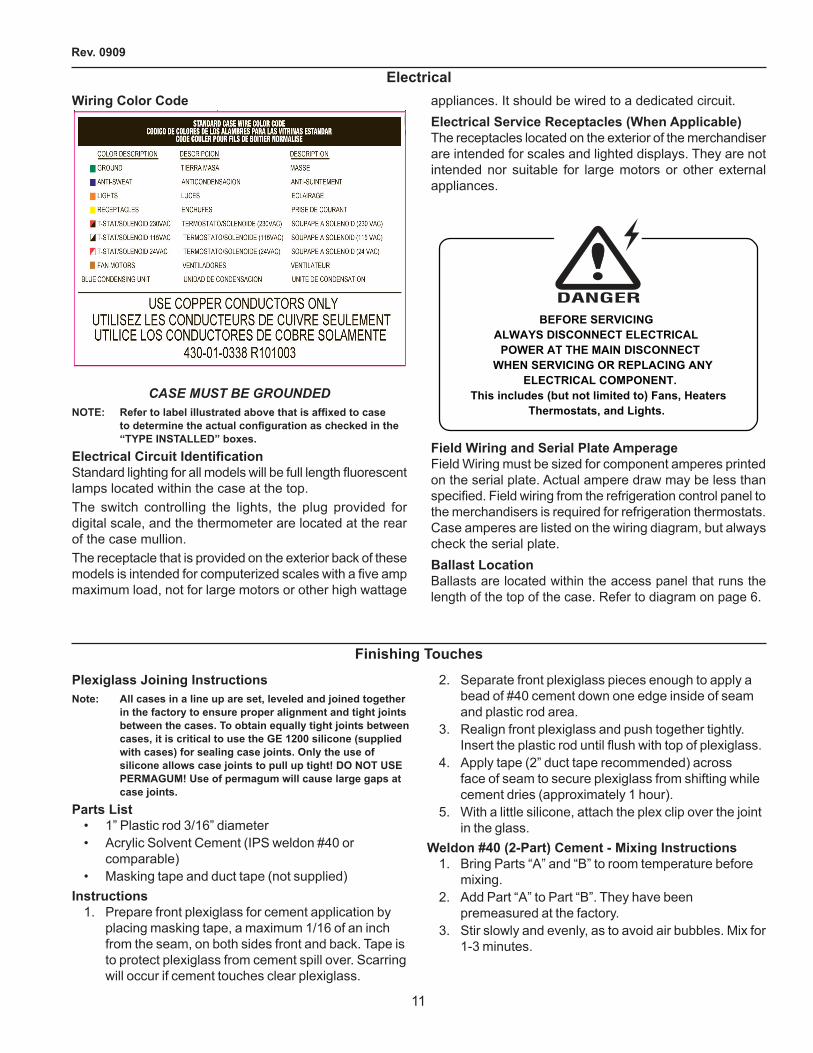
BEFORE SERVICINGALWAYS DISCONNECT ELECTRICAL
POWER AT THE MAIN DISCONNECTWHEN SERVICING OR REPLACING ANY
ELECTRICAL COMPONENT.This includes (but not limited to) Fans, Heaters
Thermostats, and Lights.
Field Wiring and Serial plate AmperageField Wiring must be sized for component amperes printed on the serial plate. Actual ampere draw may be less than specified. Field wiring from the refrigeration control panel to the merchandisers is required for refrigeration thermostats. Case amperes are listed on the wiring diagram, but always check the serial plate.Ballast LocationBallasts are located within the access panel that runs the length of the top of the case. Refer to diagram on page 6.
electricalWiring Color Code
CASEMUSTBEGROUNDEDNOTE: Refer to label illustrated above that is affixed to case
to determine the actual configuration as checked in the “TYpe InSTALLeD” boxes.
Electrical Circuit IdentificationStandard lighting for all models will be full length fluorescent lamps located within the case at the top.The switch controlling the lights, the plug provided for digital scale, and the thermometer are located at the rear of the case mullion.The receptacle that is provided on the exterior back of these models is intended for computerized scales with a five amp maximum load, not for large motors or other high wattage
Finishing Touches
plexiglass Joining Instructionsnote: All cases in a line up are set, leveled and joined together
in the factory to ensure proper alignment and tight joints between the cases. To obtain equally tight joints between cases, it is critical to use the Ge 1200 silicone (supplied with cases) for sealing case joints. Only the use of silicone allows case joints to pull up tight! DO nOT USe peRMAGUM! Use of permagum will cause large gaps at case joints.
parts List• 1” Plastic rod 3/16” diameter• Acrylic Solvent Cement (IPS weldon #40 or
comparable)• Masking tape and duct tape (not supplied)
Instructions1. Prepare front plexiglass for cement application by
placing masking tape, a maximum 1/16 of an inch from the seam, on both sides front and back. Tape is to protect plexiglass from cement spill over. Scarring will occur if cement touches clear plexiglass.
�. Separate front plexiglass pieces enough to apply a bead of #40 cement down one edge inside of seam and plastic rod area.
3. Realign front plexiglass and push together tightly. Insert the plastic rod until flush with top of plexiglass.
4. Apply tape (�” duct tape recommended) across face of seam to secure plexiglass from shifting while cement dries (approximately 1 hour).
5. With a little silicone, attach the plex clip over the joint in the glass.
Weldon #40 (2-part) Cement - Mixing Instructions1. Bring Parts “A” and “B” to room temperature before
mixing.�. Add Part “A” to Part “B”. They have been
premeasured at the factory.3. Stir slowly and evenly, as to avoid air bubbles. Mix for
1-3 minutes.

IGIC-CIDM-0909
1�
User InformationStockingImproper temperature and lighting will cause serious product loss. Discoloration, dehydration and spoilage can be controlled with proper use of the equipment and handling of product. Product temperature should always be maintained at a constant and proper temperature. This means that from the time the product is received, through storage, preparation and display, the temperature of the product must be controlled to maximize life of the product. Hussmann cases were not designed to “heat up” or “cool down” product - but rather to maintain an item’s proper temperature for maximum shelf life. To achieve the protection required always:
1. Minimize processing time to avoid damaging temperature rise to the product. Product should be at proper temperature.
�. Keep the air in and around the case area free of foreign gasses and fumes or food will rapidly deteriorate.
3. Maintain the display merchandisers temperature controls as outlined in the refrigerator section of this manual.
4. Do not place any product into these refrigerators until all controls have been adjusted and they are operating at the proper temperature. Allow merchandiser to operate a minimum of 6 hours before stocking with any product.
5. When stocking, never allow the product to extend beyond the recommended load limit. Air discharge and return air flow must be unobstructed at all times to provide proper refrigeration.
6. Avoid the use of supplemental flood or spot lighting. Display light intensity has been designed for maximum visibility and product life at the factory. The use of higher output fluorescent lamps (H.O.and V.H.O.),will shorten the shelf life of the product.
Case CleaningLong life and satisfactory performance of any equipment are dependent upon the care given to it. To insure long life, proper sanitation and minimum maintenance costs, the refrigerator should be thoroughly cleaned frequently. SHUT OFF FAN DURING CLEANING PROCESS. It can be unplugged within the case, or shut off case at the source. The interior bottom may be cleaned with any domestic soap or detergent based cleaners. Sanitizing solutions will not harm the interior bottom, however, these solutions should always be used according to the manufacturer’s directions. It is essential to establish and regulate cleaning procedures.This will minimize bacteria causing discoloration which leads to degraded product appearance and significantly shortening product shelf life.Soap and hot water are not enough to kill this bacteria. A sanitizing solution must be included with each cleaning process to eliminate this bacteria.
1. Scrub thoroughly, cleaning all surfaces, with soap and hot water.
2. Rinse with hot water, but do not flood.3. Apply the sanitizing solution according to the
manufacturer’s directions.4. Rinse thoroughly.5. Dry completely before resuming operation.
Cleaning Glass and MirrorsOnly use a soft cloth and mild glass cleaner for cleaning any glass or mirrored components. Be sure to rinse and/or dry completely.never use hot water on cold glass surfaces! It may shatter and cause serious injury! Allow glass surfaces to warm first.
Finishing Touches (Cont'd)4. Apply cement with applicator to one or both
surfaces. Join immediately.5. Apply just enough pressure to remove any air
bubbles. Do not squeeze joint so hard as to force cement out of the joint - A dry joint may result.
6. Allow approximately 4 hours to dry (at 70° F).
Acrylic CementPlastic Rod
Masking Tape

Rev. 0909
13
BEFORE SERVICINGAlways disconnect electrical power at the main
disconnect when servicing or replacing anyelectrical component.
This includes (but not limited to) Fans, Heaters,Thermostats and Lights.
Replacing Fluorescent LampsFluorescent lamps are furnished with a shatterproof protective coating. The same type of lamp with protective coating must be used if replaced. T-5 BulbsPlease note: T-5 lights must be turned off and on after bulb replacement.
This lamp has been treated to resist breakage and must be replaced with a similarly treated lamp in order to maintain
compliance with NSF Standards. NSF CODE 4.28.1
Contact HUSSMAN Chino for replacement.1-800-395-9229 X 2131
evaporator FansThe evaporator fans are located at the center front of these merchandisers directly beneath the display pans. Should fans or blades need servicing, always replace fan blades with the raised embossed side of the blade TOWARD THE MOTOR.Copper CoilsThe copper coils used in Hussmann merchandisers may be repaired in the field. Materials are available from local refrigeration wholesalers.Hussmann recommends using #15 Sil-Fos for repairs.Tips and TroubleshootingBefore calling for service, check the following:
1. Check electrical power supply to the equipment for connection.
2. Check fixture loading. Overstocking case will affect its proper operation.
FOR PROMPT SERVICEWhen contacting the factory,
be sure to have the Case Model and SerialNumber handy. This information is on a plate
located on the case itself.
CLEANING PRECAUTIONS When cleaning: • Do not use high pressure water hoses • Do not introduce water faster then waste outlet can drain • NEVER INTRODUCE WATER ON SELF CONTAINED UNIT
WITH AN EVPORATOR PAN • NEVER USE A CLEANING OR SANITIZING SOLUTION
THAT HAS AN OIL BASE (these will dissolve the butyl sealants) or an AMMONA BASE (this will corrode the copper components of the case)
• TO PRESERVE THE ATTRACTIVE FINISH: • DO USE WATER AND A MILD DETERGENT FOR THE
EXTERIOR ONLY • DO NOT USE A CHLORANITED CLAENER ON ANY
SURFACE • DO NOT USE ABRASIVES OR STEEL WOOL SCOURING
PADS (these will mar the finish)
CAUTION
plexiglass and Acrylic CareImproper cleaning not only accelerates the cleaning cycle but also degrades the quality of this surface. Normal daily buffing motions can generate static cling attracting dust to the surface. Incorrect cleaning agents or cleaning cloths can cause micro scratching of the surface, causing the plastic to haze over time.
CleaningHussmann recommends using a clean damp chamois, or a paper towel marketed as dust and abrasive free with 210® plastic Cleaner and polish available by calling Sumner Labs at 1-800-542-8656. Hard, rough cloths or paper towels will scratch the acrylic and should not be used.Antistatic CoatingsThe 210® has proven to be very effective in not only cleaning and polishing the Plexiglass surface, but also providing anti-static and anti-fog capabilities. This product also seals pores and provides a protective coating.Installing perimeter plexiglass
1. If necessary, remove Boston cart bumper�. Loosen screws holding Boston onto case. If a piece
of front plexiglass has to be removed, gently slide it upwards taking care not to damage foam located on inside of glass.
Maintenance
User Information (Cont'd)
IGIC-CIDM-0909
14
Stainless Steel Cleaning and CareThere are three basic things, which can break down your stainless steel’s passivity layer and allow corrosion.
1. Mechanical Abrasion Mechanical Abrasion means those things that
will scratch the steels surface. Steel Pads, wire Brushes, and Scrapers are prime examples.
2. Water Water comes out of our tap in varying degrees of
hardness. Depending on what part of the country you live in, you may have hard or soft water. Hard water may leave spots. Also, when heated, hard water leaves deposits behind that if left to sit, will break down the passive layer and rust your stainless steel. Other deposits from food preparation and service must be properly removed.
3. Chlorides Chlorides are found nearly everywhere. They
are in water, food and table salt. One of the worst perpetrators of chlorides can come from household and industrial cleaners.
Don’t Despair! Here are a few steps that can help prevent stainless steel rust.
1. Use the proper Tools When cleaning your stainless steel products, take
care to use non-abrasive tools. Soft Clothes and plastic scouring pads will NOT harm the steel’s passive layer. Stainless steel pads can also be used but the scrubbing motion must be in the same direction of the manufacturer’s polishing marks.
2. Clean With the polish Lines Some stainless steels come with visible polishing
lines or “grain”. When visible lines are present, you should ALWAYS scrub in a motion that is parallel to them. When the grain cannot be seen, play it safe and use a soft cloth or plastic scouring pad.
Maintenance (Cont'd)
electrical Wiring Diagrams
CIDM-E S/C w OMNISTAT W0300008 CIDM-I S/C w OMNISTAT W0300009 CIDM-E S/C w MR4 1H�4199 CIDM-I S/C w MR4 1H�4198
3. Use Alkaline, Alkaline Chlorinated or non-chloride Containing Cleaners
While many traditional cleaners are loaded with chlorides, the industry is providing an ever increasing choice of non-chloride cleaners. If you are not sure of your cleaner’s chloride content contact your cleaner supplier. If they tell you that your present cleaner contains chlorides, ask for an alternative. Also, avoid cleaners containing quaternary salts as they also can attack stainless steel & cause pitting and rusting.
4. Treat your Water Though this is not always practical, softening hard
water can do much to reduce deposits. There are certain filters that can be installed to remove distasteful and corrosive elements. Salts in a properly maintained water softener are your friends. If you are not sure of the proper water treatment, call a treatment specialist.
5. Keep your Food equipment Clean Use alkaline, alkaline chlorinated or non-chlorinated
cleaners at recommended strength. Clean frequently to avoid build-up of hard, stubborn stains. If you boil water in your stainless steel equipment, remember the single most likely cause of damage is chlorides in the water. Heating cleaners that contain chlorides has a similar effect.
6. RInSe, RInSe, RInSe If chlorinated cleaners are used you must rinse,
rinse, rinse and wipe dry immediately. The sooner you wipe off standing water, especially when sit contains cleaning agents, the better. After wiping the equipment down, allow it to air dry for the oxygen helps maintain the stainless steel’s passivity film.
7. never Use Hydrochloric Acid (Muriatic Acid) on Stainless Steel
8. Regularly Restore/passivate Stainless Steel

Rev. 0909
15
Wiring Diagrams
DA
TE:
PR
OJE
CT
TITL
E:
DR
AWIN
G #
:D
RA
WN
BY
:
PR
OD
UC
TIO
N O
RD
ER
#:
DR
AW
ING
TIT
LE:
DA
TE:
Hus
sman
n C
orpo
ratio
n, In
t'l.
1377
0 R
amon
a A
venu
eC
hino
, CA
. 917
10(9
09)-
590-
4910
Lic
.#: 6
4440
6
RE
VIS
ION
S:
#:
DE
SC
RIP
TIO
N:
CH
EC
KE
D B
Y:
BY
:
FILE
LO
CA
TIO
N:R
aym
ond
Twoh
y
PA
GE
O
F1
1
02/0
2/05
A
Upd
ated
dw
g, re
vise
d lo
ads,
con
d fa
n w
iring
cha
nge
6/2
7/07
J
R
7-11
W03
0000
8
CID
M-E
w/ O
MN
I STA
T
~208
/ 24
0 V
AC
- 50
/60
Hz
L1 L2 L3 N G
INSI
DE P
ERIM
ETER
LIG
HTS
(2)
125-
03-1
075
F15/
T8/S
PX30
(1)
125-
03-1
071
F17
/T8/
SPX3
0
OU
TSID
E PE
RIM
ETER
LIG
HTS
(3)
125-
03-1
071
F17/
T8/S
PX30
BA
LLA
ST
125-
01-3
266
FULH
AM
LH
3-12
0-L
BA
LLA
ST
125-
01-3
266
FULH
AM
LH
3-12
0-L
EV
AP
FA
N M
OTO
RS
(2) G
E-9W
CW
W0.
6A @
120
V12
5-01
-061
5A
DE
FRO
ST
TIM
ER
OM
NI-S
TAT
230V
-50
/60
Hz.
125-
01-2
300
L1
PO
WE
R S
WIT
CH
CO
ND
ENSE
R F
AN~2
08 V
AC
L2
* P
RO
D. T
EM
P. S
EN
SO
R L
OC
ATE
DO
N E
XTE
RN
AL
CA
D W
ALL
NE
XT T
OTH
ER
MO
STA
T P
RO
BE
** A
IR T
EM
P. S
EN
SO
R L
OC
ATE
D O
NTO
P C
EN
TER
CAD
DIV
IDE
R
***
MO
TOR
STA
RT
SW
ITC
HS
QU
AR
E "D
" 554
4712
5-01
-027
1
OM
NI S
TAT
PN
9529
11-2
30V
AC
POW
ER
SU
PP
LY23
0 V
acP
RO
D.
TEM
P.
AIR
TEM
P.
L
91
23
45
67
8
CO
ND
ENS
ING
UN
ITS
- C
OPE
LAN
D®
F9AM
-A10
3-C
FV-1
40 /
1 H
.P. /
R-2
2R
LA=
9.5
1857
WM
CC
= 13
.7LR
A=
43.3
225-
03-0
121
1RC
ON
DEN
SIN
G U
NIT
MM
LIG
HT
CIR
CU
IT=
.91A
, 98W
M
CR
TL P
RS
R D
UAL
225-
01-0
706B
BLK
# 1
4R
ED
# 1
4
WH
T #
14
WH
T #
14
RED
# 1
4
BLK
# 1
4R
ED #
14
MC
A=
7.8A
MO
P=
15A
SA
FETY
SW
ITC
H
FLO
AT
SW
ITC
H
FIS
HE
R™
EV
AP
OW
AY™
DM
15W
W-3
D15
00W
@ ~
240
VA
C6.
25A
125-
01-0
765A
~208
/ 24
0 V
AC
- 50
/60
Hz.
BU
ND
LEP
UR
PLE
LAB
ELE
DE
VA
P P
AN
CIR
CU
ITL1
L2
BLACK # 14
RED # 14
BLK
# 1
4
RE
D #
14
CIR
CU
IT #
2 15
00W
@ 2
40V
AC
,11
27W
@ 2
08V
AC
NO
TE: C
AS
E M
US
TB
E G
RO
UN
DE
D
6.3
6.3
5.4
5.4
L1 L2 L3
208
V 2
40 V
LOA
DIN
G
TER
MIN
AL
BLO
CK
125-
01-0
295
CIR
CU
IT #
1
NO
TE: C
AS
E M
US
TBE
GR
OU
ND
ED
L1 L2 L3
208
V 2
40 V
LOA
DIN
GC
IRC
UIT
#1
1973
W
NO
TE: C
AS
E M
US
TBE
GR
OU
ND
ED10.4
10.7
9.2
9.5
L1 L2 L3
208
V 2
40 V
LOA
DIN
G
Cas
e Pa
ram
eter
s: •
Def
rost
Set
tings
6
times
/day
30m
ins
Off
tim
e M
ax a
ir te
mp
mea
sure
d at
hon
eyco
mb
55F~
60F
• Te
mpe
ratu
re R
ange
45m
ins o
ut o
f def
rost
26
F~31
F re
ar w
all
29F~
33F
hone
ycom
b •
Air
Flow
Mea
sure
d w
ith a
Jr.
250~
325
FPM
rear
wal
l 18
0~23
0 FP
M H
oney
com
b 18
0~25
0 Sh
elve
s 15
0~20
0 D
eck

IGIC-CIDM-0909
16
DA
TE:
PR
OJE
CT
TITL
E:
DR
AWIN
G #
:D
RA
WN
BY
:
PR
OD
UC
TIO
N O
RD
ER
#:
DR
AW
ING
TIT
LE:
DA
TE:
Hus
sman
n C
orpo
ratio
n, In
t'l.
1377
0 R
amon
a A
venu
eC
hino
, CA
. 917
10(9
09)-
590-
4910
Lic
.#: 6
4440
6
RE
VIS
ION
S:
#:
DE
SC
RIP
TIO
N:
CH
EC
KE
D B
Y:
BY
:
FILE
LO
CA
TIO
N:R
aym
ond
Twoh
y
PA
GE
O
F1
1
02/0
2/05
7-11
W03
0000
9
CID
M-I
w/ O
MN
I STA
TA
U
pdat
ed d
wg,
revi
sed
load
s, c
ond
fan
wiri
ng c
hang
e 6
/27/
07
JR
~208
/ 24
0 V
AC
- 50
/60
Hz
L1 L2 L3 N G
EV
AP
FAN
MO
TOR
S(2
) 4W
SP
CW
.29A
@ 1
20 V
0392
457
DE
FRO
ST
TIM
ER
OM
NI-S
TAT
230V
-50
/60
Hz.
125-
01-2
300
L1
PO
WE
R S
WIT
CH
CO
ND
ENSE
R F
AN~2
08 V
AC
L2
* P
RO
D. T
EM
P. S
EN
SO
R L
OC
ATE
DO
N E
XTE
RN
AL
CA
D W
ALL
NE
XT T
OTH
ER
MO
STA
T P
RO
BE
** A
IR T
EM
P. S
EN
SO
R L
OC
ATE
D O
NTO
P C
EN
TER
CAD
DIV
IDE
R
***
MO
TOR
STA
RT
SW
ITC
HS
QU
AR
E "D
" 554
4712
5-01
-027
1
OM
NI S
TAT
PN
9529
11-2
30V
AC
POW
ER
SU
PP
LY23
0 V
acP
RO
D.
TEM
P.
AIR
TEM
P.
L
91
23
45
67
8
CO
ND
ENS
ING
UN
ITS
- C
OPE
LAN
D®
F9AM
-A10
3-C
FV-1
40 /
1 H
.P. /
R-2
2R
LA=
9.5
1857
WM
CC
= 13
.7LR
A=
43.3
225-
03-0
121
1RC
ON
DEN
SIN
G U
NIT
MM
LIG
HT
CIR
CU
IT=
.93A
, 100
W
M
CR
TL P
RS
R D
UAL
225-
01-0
706B
BLK
# 1
4R
ED
# 1
4
WH
T #
14
WH
T #
14
RED
# 1
4
BLK
# 1
4R
ED #
14
MC
A=
7.8A
MO
P=
15A
SA
FETY
SW
ITC
H
FLO
AT
SW
ITC
H
FIS
HE
R™
EV
AP
OW
AY™
DM
15W
W-3
D15
00W
@ ~
240
VA
C6.
25A
125-
01-0
765A
~208
/ 24
0 V
AC
- 50
/60
Hz.
BU
ND
LEP
UR
PLE
LAB
ELE
DE
VA
P P
AN
CIR
CU
ITL1
L2
BLACK # 14
RED # 14
BLK
# 1
4
RE
D #
14
CIR
CU
IT #
2 15
00W
@ 2
40V
AC
,11
27W
@ 2
08V
AC
NO
TE: C
AS
E M
US
TB
E G
RO
UN
DE
D
6.3
6.3
5.4
5.4
L1 L2 L3
208
V 2
40 V
LOA
DIN
G
TER
MIN
AL
BLO
CK
125-
01-0
295
F25/
T8/S
PX3
0(2
) 125
-03-
1072
F25/
T8/S
PX3
0(2
) 125
-03-
1072
BA
LLA
ST
125-
01-3
266
FULH
AM
LH
3-12
0-L
BA
LLA
ST
125-
01-3
266
FULH
AM
LH
3-12
0-L
CIR
CU
IT #
1
NO
TE: C
AS
E M
US
TBE
GR
OU
ND
ED
L1 L2 L3
208
V 2
40 V
LOA
DIN
GC
IRC
UIT
#1
1965
W
NO
TE: C
AS
E M
US
TBE
GR
OU
ND
ED10.4
10.1
9.2
8.9
L1 L2 L3
208
V 2
40 V
LOA
DIN
G
Cas
e Pa
ram
eter
s:
• D
efro
st S
ettin
gs
6 tim
es/d
ay 3
0min
s O
ff ti
me
Max
air
tem
p m
easu
red
at h
oney
com
b 55
F~60
F •
Tem
pera
ture
Ran
ge 4
5min
s out
of d
efro
st
26F~
31F
rear
wal
l 29
F~33
F ho
neyc
omb
• A
ir Fl
ow M
easu
red
with
a Jr
. 25
0~32
5 FP
M re
ar w
all
180~
230
FPM
Hon
eyco
mb
Wiring Diagrams (Cont'd)

Rev. 0909
17
Wiring Diagrams (Cont'd)
DA
TE:
PR
OJE
CT
TITL
E:
DR
AWIN
G #
:D
RA
WN
BY
:
PR
OD
UC
TIO
N O
RD
ER
#:
DR
AW
ING
TIT
LE:
DA
TE:
Hus
sman
n C
orpo
ratio
n, In
t'l.
1377
0 R
amon
a A
venu
eC
hino
, CA
. 917
10(9
09)-5
90-4
910
L
ic.#
: 644
406
RE
VIS
ION
S:
#:
DE
SC
RIP
TIO
N:
CH
EC
KE
D B
Y:
BY
:
FILE
LO
CA
TIO
N:JE
SS
E R
IOS
PA
GE
O
F
?
1
7/21
/09
12
B
Add
ed e
xter
nal r
elay
7
/31/
09
JR
CID
M-E
1H24
199
CID
M-E
w/ M
R4
~208
/ 24
0 V
AC
- 50
/60
Hz
L1 L2 L3 N G
INSI
DE P
ERIM
ETER
LIG
HTS
(2)
125-
03-1
075
F15/
T8/S
PX30
(1)
125-
03-1
071
F17
/T8/
SPX3
0
OU
TSID
E PE
RIM
ETER
LIG
HTS
(3)
125-
03-1
071
F17/
T8/S
PX30
BA
LLA
ST
125-
01-3
266
FULH
AM
LH
3-12
0-L
BA
LLA
ST
125-
01-3
266
FULH
AM
LH
3-12
0-L
EV
AP
FA
N M
OTO
RS
(2) G
E-9W
CW
W0.
6A @
120
V12
5-01
-061
5A
L1
PO
WE
R S
WIT
CH
CO
ND
EN
SE
R F
AN
~208
VA
CL2
* P
RO
D. T
EM
P. S
EN
SO
R L
OC
ATE
DO
N E
XTER
NAL
CA
D W
ALL
NE
XT T
OTH
ER
MO
STA
T P
RO
BE
** A
IR T
EM
P. S
EN
SO
R L
OC
ATE
D O
NTO
P C
EN
TER
CAD
DIV
IDE
R
MO
TOR
STA
RT
SW
ITC
HS
QU
AR
E "D
" 554
4712
5-01
-027
1
CO
ND
EN
SIN
G U
NIT
S -
CO
PELA
ND
®F9
AM
-A10
3-C
FV-1
40 /
1 H
.P. /
R-2
2R
LA=
9.5
1857
WM
CC
= 13
.7LR
A=
43.3
225-
03-0
121
1RC
ON
DEN
SIN
G U
NIT
MM
LIG
HT
CIR
CU
IT=
.91A
, 98W
M
BLK
# 1
4R
ED
# 1
4
WH
T #
14
WH
T #
14
RED
# 1
4
BLK
# 1
4R
ED
# 1
4
MC
A= 7
.8A
MO
P= 1
5A
SA
FETY
SW
ITC
H
FLO
AT
SW
ITC
H
FIS
HE
R™
EV
AP
OW
AY™
DM
15W
W-3
D15
00W
@ ~
240
VA
C6.
25A
125-
01-0
765A
~208
/ 24
0 V
AC
- 50
/60
Hz.
BUN
DLE
PU
RP
LELA
BE
LED
EV
AP
PA
NC
IRC
UIT
L1
L2
BLACK # 14
RED # 14
BLK
# 1
4
CIR
CU
IT #
2 15
00W
@ 2
40V
AC
,11
27W
@ 2
08V
AC
NO
TE: C
AS
E M
US
TB
E G
RO
UN
DE
D
6.3
6.3
5.4
5.4
L1 L2 L3
208
V 2
40 V
LOA
DIN
G
TER
MIN
AL
BLO
CK
125-
01-0
295
RED
# 1
4
RE
LAY
OM
RO
NG
7L-2
A-T
UB
J-C
B-24
0A12
5-01
-318
2A
CIR
CU
IT #
1
NO
TE: C
AS
E M
US
TBE
GR
OU
ND
ED
L1 L2
208
V 2
40 V
LOA
DIN
GC
IRC
UIT
#1
NO
TE: C
AS
E M
US
TBE
GR
OU
ND
ED10.4
10.7
9.2
9.5
208
V 2
40 V
LOA
DIN
G

IGIC-CIDM-0909
18
DA
TE:
PR
OJE
CT
TITL
E:
DR
AWIN
G #
:D
RA
WN
BY
:
PR
OD
UC
TIO
N O
RD
ER
#:
DR
AW
ING
TIT
LE:
DA
TE:
Hus
sman
n C
orpo
ratio
n, In
t'l.
1377
0 R
amon
a A
venu
eC
hino
, CA
. 917
10(9
09)-5
90-4
910
L
ic.#
: 644
406
RE
VIS
ION
S:
#:
DE
SC
RIP
TIO
N:
CH
EC
KE
D B
Y:
BY
:
FILE
LO
CA
TIO
N:JE
SS
E R
IOS
PA
GE
O
F
?
CID
M-E
w/ M
R4
22
7/21
/09
CID
M-E
1H24
199
B
Add
ed e
xter
nal r
elay
7
/31/
09
JR
Wiring Diagrams (Cont'd)

Rev. 0909
19
Wiring Diagrams (Cont'd)
DA
TE:
PR
OJE
CT
TITL
E:
DR
AWIN
G #
:D
RA
WN
BY
:
PR
OD
UC
TIO
N O
RD
ER
#:
DR
AW
ING
TIT
LE:
DA
TE:
Hus
sman
n C
orpo
ratio
n, In
t'l.
1377
0 R
amon
a A
venu
eC
hino
, CA
. 917
10(9
09)-5
90-4
910
L
ic.#
: 644
406
RE
VIS
ION
S:
#:
DE
SC
RIP
TIO
N:
CH
EC
KE
D B
Y:
BY
:
FILE
LO
CA
TIO
N:JE
SS
E R
IOS
PA
GE
O
F
?
1
7/21
/09
B
Add
ed e
xter
nal r
elay
7
/31/
09
JR
12
CID
M-I
1H24
198
CID
M-I
w/M
R4
~208
/ 24
0 V
AC
- 50
/60
Hz
L1 L2 L3 N G
EV
AP
FA
N M
OTO
RS
(2) 4
W S
P C
W.2
9A @
120
V03
9245
7
L1
PO
WE
R S
WIT
CH
CO
ND
EN
SE
R F
AN
~208
VA
C
L2
* P
RO
D. T
EM
P. S
EN
SO
R L
OC
ATE
DO
N E
XTER
NAL
CAD
WAL
L N
EXT
TO
THE
RM
OS
TAT
PR
OBE
** A
IR T
EMP.
SEN
SOR
LO
CAT
ED
ON
TOP
CE
NTE
R C
AD D
IVID
ER
MO
TOR
STA
RT
SW
ITC
HS
QU
AR
E "D
" 554
4712
5-01
-027
1
CO
ND
ENSI
NG
UN
ITS
- CO
PE
LAN
D®
F9A
M-A
103-
CFV
-140
/ 1
H.P
. / R
-22
RLA
= 9.
5 18
57 W
MC
C=
13.7
LRA
= 43
.322
5-03
-012
1
1RC
ON
DEN
SIN
G U
NIT
MM
LIG
HT
CIR
CU
IT=
.93A
, 100
W
M
BLK
# 1
4R
ED
# 1
4
WH
T #
14
WH
T #
14
RE
D #
14
BLK
# 1
4R
ED #
14
MC
A=
7.8A
MO
P=
15A
SA
FETY
SW
ITC
H
FLO
AT
SW
ITC
H
FIS
HE
R™
EV
AP
OW
AY™
DM
15W
W-3
D15
00W
@ ~
240
VA
C6.
25A
125-
01-0
765A
~208
/ 24
0 V
AC
- 50
/60
Hz.
BU
ND
LEP
UR
PLE
LAB
ELE
DE
VA
P P
AN
CIR
CU
ITL1
L2
BLACK # 14
RED # 14
BLK
# 1
4
CIR
CU
IT #
2 15
00W
@ 2
40V
AC
,11
27W
@ 2
08V
AC
NO
TE: C
AS
E M
US
TB
E G
RO
UN
DE
D
6.3
6.3
5.4
5.4
L1 L2 L3
208
V 2
40 V
LOA
DIN
G
TER
MIN
AL
BLO
CK
125-
01-0
295
F25/
T8/S
PX3
0(2
) 125
-03-
1072
F25/
T8/S
PX3
0(2
) 125
-03-
1072
BA
LLA
ST
125-
01-3
266
FULH
AM
LH
3-12
0-L
BA
LLA
ST
125-
01-3
266
FULH
AM
LH
3-12
0-L
RED
# 1
4
RE
LAY
OM
RO
NG
7L-2
A-T
UB
J-C
B-2
40A
125-
01-3
182A
CIR
CU
IT #
1
NO
TE: C
AS
E M
US
TBE
GR
OU
ND
ED
208
V 2
40 V
LOA
DIN
GC
IRC
UIT
#1
NO
TE: C
AS
E M
US
TBE
GR
OU
ND
ED10.4
10.1
9.2
8.9
L1 L2
208
V 2
40 V
LOA
DIN
G
IGIC-CIDM-0909
�0
DA
TE:
PR
OJE
CT
TITL
E:
DR
AWIN
G #
:D
RA
WN
BY
:
PR
OD
UC
TIO
N O
RD
ER
#:
DR
AW
ING
TIT
LE:
DA
TE:
Hus
sman
n C
orpo
ratio
n, In
t'l.
1377
0 R
amon
a A
venu
eC
hino
, CA
. 917
10(9
09)-5
90-4
910
L
ic.#
: 644
406
RE
VIS
ION
S:
#:
DE
SC
RIP
TIO
N:
CH
EC
KE
D B
Y:
BY
:
FILE
LO
CA
TIO
N:JE
SS
E R
IOS
PA
GE
O
F
?
22
CID
M-I
w/M
R4
7/21
/09
CID
M-I
1H24
198
B
Add
ed e
xter
nal r
elay
7
/31/
09
JR
Wiring Diagrams (Cont'd)

Rev. 0909
�1
CID Mini With OmnistatInstaller Information Reference SheetInstallersThe CIDM has a Sporland Omnistat Time Clock that is factory programmed; therefore, the Setpoint and Defrost setting does not require setting (Omnistat is locked at factory and requires unlocking before setting)Start-up/Checklist
1. Verify power to equipment connection point (See Figure 1)
�. Turn power switch on (located below unit in a 4” x 6” box). See Figure �.
3. The case requires two compressor cycle temperatures before any setting can be verified.
4. If Setpoint or Defrost setting needs to be verified see page �7 of Installation & Operation Manual.
Figure 1
Figure 2Sporland Omnistat Time Clock program Settings

IGIC-CIDM-0909
��
LIST OF pARAMeTeRS
Display parameter Type Min Max Unit Defaultvalue CIDM
pS pASSWORD F 0 199 - �� 22/ pROBe pARAMeTeRS
/C ambient probe calibration (x 0.1°C/°F) F -1�7 1�7 °C/°F 0.0 0.0/� Measurement stability C 1 15 - 4 4/4 probe display: 0 = regulation probe, 1 = product food probe (second probe) C 0 1 flag 0 1/5 °C/°F (0=°C, 1=°F) C 0 1 flag 0 1r ReGULATOR pARAMeTeRSrd Regulating differential (hysteresis 0=0.5 °C/ °F) F 0 19 °C/°F � 8r1 Minimum allowable set C -50 r� °C/°F -50 26°Fr� Maximum allowable set Cr1 1�7 °C/°F 60 C r1 1�7 °C/°F 60 32°Fr3 Enabling Ed alarm: max duration of defrost is reached (0 = no, 1 = yes) C 0 1 flag 0 0r4 Automatic variation of the Set-Point with closed curtain-switch (A4=4) C -�0 �0 °C/°F 3 nU*c COMpReSSOR pARAMeTeRSc0 Delay in the compressor start-up after switch-on C 0 15 min 0 1c1 Minimum time between two following compressor start-ups C 0 15 min 0 1c� Compressor shutdown minimum time C 0 15 min 0 1c3 Compressor operation minimum time C 0 15 min 0 2c4 Safety compressor (0 = OFF, 100 = ON) C 0 100 min 0 10cc Continuous cycle duration C 0 15 hours 4 2c6 Alarm delay after continuous cycle C 0 15 hours � 6d DeFROST pARAMeTeRSd0 defrost type (0 = heater, 1 = hot gas, � = time resistance, 3 = time hot gas) C 0 3 flag 0 2d1 Time interval between two defrost cycles F 0 199 hours 8 4dt End defrost temperature F -50 1�7 °C/°F 4 60dP Max defrost duration or effective duration if d0=� or 3 F 1 199 min 30 25d4 Defrost after start-up (0 = no, 1 = yes) C 0 1 flag 0 0d5 Delay defrost after control Switch-On or from digital input (A4 or A5=4) C 0 199 min 0 0d6 Block temperature display during defrost (0 = no, 1 = yes) C 0 1 flag 1 1dd Dripping time after defrost F 0 15 min � 0d8 Alarm delay after defrost F 0 15 hours 1 2d9 defrost priority over compressor protection (0 = no, 1 = yes) C 0 1 flag 0 0d/ Temperature defrost probe display F - - °C/°F - -dC Time base (0=hours/min, 1=min/s) Only for dl and dP C 0 1 flag 0 0A ALARM pARAMeTeRSA0 Alarms and fans differential (0=0.5 °C/°F) C 0 19 °C/°F 0 0AL Low temperature alarm (max. variation as to the Set-Point). AL=0 excluded Low temperature alarm F 0 1�7 °C/°F 0 0AH High temperature alarm (max. variation as to the Set-Point). AH=0 excluded High temperature alarm F 0 1�7 °C/°F 0 0Ad Temperature alarm delay C 0 199 min 0 0A7 Measurement delay time for the input “delayed alarm” (A4 or A5=�) C 0 199 min 0 nU*F FAn pARAMeTeRS
F0 Management of fans: 0=fans ON, specific phases excluded (F2, F3 and Fd) 1 = fans ON (dependent on parameter F1) specific phases excluded
C 0 1 flag 0 n/A
F1 Fan power on temperature F -50 1�7 °C/°F 5 n/AF� Fans OFF when the compressor is OFF (0 = no, 1 = yes) C 0 1 flag 1 n/AF3 Fans OFF during defrost (0 = no, 1 = yes) C 0 1 flag 1 n/AFd Stop after dripping ON for each F0 value F 0 15 min 1 n/AH OTHeR SeLeCTIOnS
H0 Serial address C 0 199 - 1 1H1 Selection of the alarm relay operation 0=alarm ON, energized relay, 1= alarm ON, disenergized relay C 0 1 flag 1 1H� 0=disabled buttons, 1=enabled buttons C 0 1 flag 1 0H5 Identification code for programming key (programmed by supervisor) F -99 199 - - -T External parameter programming C -99 99 - 0 0
*show the set valueNU*: not used parameter, leave the default value
please contact Sporlan valve Company for further information. www.sporIan.com
Sporland Omnistat Time Clock program Settings (Cont'd)

Rev. 0909
�3
SAFeTY STAnDARD: in compliance with the european laws.Installation precautions• the connection cables should be suitable for up to 195°F operation;
Caution: Low voltage and probe wiring must be properly separated from high voltage wiring
DISpLAYDuring normal working conditions, the display shows the value measured by the air regulation probe or by the second probe (parameter /4). In case of active alarm, the temperature flashes alternatively to the code alarm.
ALARMS AnD SIGnALS
Alarm code DescriptionE0 fault air regulation probeE1 evaporator product/food probe fault digital input alarmIA immediate external alarm (A4 and A7 parameters)LO low temperature alarm (AL, Ad and A0 parameters)HI high temperature alarm (AH, Ad and A0 parameters)EE data acquisition failure (see the manual for the default procedure)Ed timeout-ended defrost (dt, dP and r3 parameters)dF defrost in progress
OpeRATInG InSTRUCTIOnS On THe DISpLAY
• LED Button indicates compressor ON;• LED Button indicates defrosting ON;
• LED Button indicates presence of alarms.The blinking indicates that controller is waiting for a time delay to expire.
SeT pOInT (desired temperature value)
• Press the SET button for one second to display the Set-Point value;• After few seconds, the set value blinks;
• Press UP or DOWN to increase or decrease the set-point value; press the button once/more to confirm the new value.
MAnUAL DeFROSTBesides the automatic defrost; it is possible to activate a manual defrost by pressing the button for more than 5 seconds (it occurs only in the appropriate temperature conditions).
ACCeSS AnD MODIFICATIOn OF THe FReQUenT pARAMeTeRS (F TYpe)
1) Press the button for more than 5 seconds (in case of alarm, first silence the buzzer);�) the display displays PS;
3) Press or to show the parameter whose value has to be changed; press to display the associated value;
4) Press or to change the value;
5) Press to temporarily confirm the new value and go back to display the parameter code; In order to modify the other parameters, start back from point 3.
Storage of the new values: press at least for 5 seconds to store the new value and exit the "PARAMETERS MODIFICATION" procedure. For timing parameters only: switch off and switch on the controller in order to make them immediately effective without waiting for the following cycle. To exit without modifying any parameter: do not press any button for at least 60 seconds (TIME OUT).
Sporland Omnistat Time Clock program Settings (Cont'd)

IGIC-CIDM-0909
�4
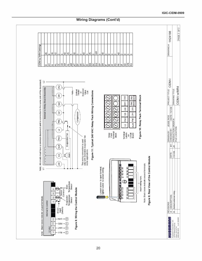
MR4 Time Clock program Settings
programming the ControlUse this section to program the control module. After programming, the control module reatins its programmed settings, even in the event of power failure or power down.Using the Control ModuleDuring normal operation, the display shows the main sensor temperature. See Figure �.
• Press Up or Down repeatedly to scroll through the main sensor temperature, evaporator sensor temperature and the binary input status.
• Press Enter to display the setpoint.After 15 seconds of inactivity, the display returns to main sensor temperature.Unlocking or Locking Access to programming
1. In sequence, press and hold Enter, Up, and then Down.�. Hold These buttons until "---" displays.3. Continue holding until the main sensor temperature displays (approximately 10 seconds).
Changing the setpoint
1. Press and hold Enter for approximately 3 seconds.�. Release Enter when the new Setpoint value displays.
3. Press Up or Down to display the new Setpoint value.
4. Press Enter to save the new setting.
note: The control ignores changes and reverts to the previous saved value unless you press enter.
Changing Other Function values
1. Press and hold Enter until XY (the code for Differential) appears (about 10 seconds). See Table 3.
�. Press Up or Down until the desired function appears. See Table 3 and Control Functions.
3. Press Enter. The function's existing value appears.
4. Press Up or Down until the desired setting value appears.
5. Press Enter to save the new value. After �0 seconds of inactivity, the display returns to normal operation.
note: The control ignores changes and reverts to the previous saved value unless you press enter.
Initiating a manual Self-TestIMpORTAnT: Disconnect controlled loads before running the self-test procedure. Reconnect controlled loads and cycle power to resume normal operation.
1. In sequence, press and hold Up and then Down.�. Hold for 5 seconds.
Initiating a Manual Defrost Cycle
Press and hold Defrost for 3 seconds to interrupt normal control operation and initiate a manual defrost cycle.
note: If the Defrost evaporator Temperature is higher than the Defrost Termination Temperature, the control does not initiate a manual defrost.
Initiating a Manual Deep Freeze Cycle
1. In sequence, press and hold Enter and Up.�. Hold both buttons for 5 seconds.3. The compressor status LED lights and the compressor output relay contacts close.

Rev. 0909
�5
Function Settings in Order of programming in Control ModuleDisplay Code Function Useable Setting Range and Unit value Factory-Set values
None Setpoint -40 to 99°F (-40 to 80°C)HY Differential 1 to 9F° (1 to 9C°) 5 (F°)LL Low Setpoint Stop -40°F (-40°C) to High Setpoint Stop -�5(°F)HL High Setpoint Stop Low Setpoint Stop to 99°F (80°C) 40(°F)CC Cycle Delay 0 to 9 minutes 1 (minutes)Co Deep Freezing Time 0 to 99 minutes 60 (minutes)AH High Temperature Alarm 0 to 50°F (0 to 50C°) 10 (F°)AL Low Temperature Alarm -50 to 0F° (-50 to 0C°) -10 (F°)Ad Alarm Differential 1 to 9F° (1 to 9C°) 5 (F°)At Alarm Time Delay 0 to 99 minutes 3 (minutes)dF Defrost Mode 0 = electric defrost
1 = hot gas defrost0 (electric defrost)
dE Defrost Termination Mode 0 = time-based 1 = temperature-based
1 (temperature-based)
dt Defrost Termination Temperature 3� to 68°F (0 to �0°C) 55(°F)di Defrost Interval 1 to 99 hours 7 (hours)dd Maximum Defrost Duration 0 to 99 minutes 45 (minutes)dC Dripping Time 0 to 99 minutes 5 (minutes)dP Display During Defrost 0 = last main sensor reading
1 = main setpoint0 (last main sensor reading)
dr Display Delay After Defrost 1 to 99 minutes �0 (minutes)iF Binary Input Mode 0 = no response
1 = compressor off, alarm on � = alarm on 3 = evap. Fan off, alarm on
0 (no response)
id Binary Input Time Delay 0 to 99 minutes 0 (minutes)FF Fan Operating Mode 0 = parallel with compressor
1 = always on0 (parallel with compressor)
Fd Fan Startup Delay 0 to 99 minutes 5 (minutes)Fr Fan Start Temperature -�� to 41°F (-30 to 5° C) 40 (°F)SF Sensor Failure Operation 0 = compressor on
1 = compressor off � = based on last four cycles
� (based on last four cycles)
So Temperature Sensor Offset -�0 to �0°F (-�0 to �0°C) 0 (F°)Un Temperature Units Used 0 = °C
1 = °F1 (°F)
PU Display Refresh Rate 1 to 99 seconds 1 (second)
MR4 Time Clock program Settings (Cont'd)

IGIC-CIDM-0909
�6
Alarm and Fault Display CodesThese alarm and fault codes flash on the LED display when the control detects the following faults.Table: Display Codes and StatusDisplay Code Alarm or Fault Condition System Status
F1 Indicates an open or shorted main temperature sensor
Alarm is on. Compressor runs according to the Sensor Failure Mode selected. Correct problem with sensor and cycle power to reset control
F� Indicates an open or shorted evaporator temperature sensor
Alarm is on. Defrost cycle is controlled by Defrost Interval and Defrost Duration. Correct problem with sensor to reset control.
A1 Binary input is open for longer than the Binary Input Time Delay and Binary Input Mode Option 1 is selected.
Alarm is on. Compressor, Defrost, and Evaporator Fan are off.
A� Binary input is open for longer than Binary Input Time Dealy and Binary Input Mpde Option � is selected.
Alarm, Compressor and Evaporator Fan are on. Defrost may e on or off.
A3 Binary input is open for longer than the Binary Input Time Delay and Binary Input Mode Option 3 selected.
Alarm and Compressor are on. Evaporator Fan is off. Defrost may be on or off.
HI Main sensor temperature has reached or exceeded the High Temperature Alarm value.
Alarm is on. Correct problem to reset control.
LO Main sensor temperature has reached or fallen below the Low Temperature Alarm value.
Alarm is on. Correct problem to reset control.
EE Indicates program failure. Alarm is on. Other outputs are off. Replace control.
MR4 Time Clock program Settings (Cont'd)

Rev. 0909
�7
CIDM w/ MR4 SettingsSI �3HY 8LL �6HL 3�CC �CO 1AH 40AL 15AD 5AT 30DF 0DE 0DT 60DI 4DD �5DC 0DU OFFDP 1DR 30IF 0ID 0FF 0FD 0FR 40SF �SO 0UN 1PU 1
MR4 Time Clock program Settings (Cont'd)

IGIC-CIDM-0909
�8
Appendix A. - Temperature Guidelines - RefrigeratedThe refrigerators should be operated according to the manufacturer’s published engineering specifications for entering air temperatures for specific equipment applications. Table 1 shows the typical temperature of the air entering the food zone one hour before the start of defrost and one hour after defrost for various categories of refrigerators. Refer to Appendix C for Field Evaluation Guidelines.
Table
Type of Refrigerator Typical entering Air Temperature
I. OPEN DISPLAY A. Non frozen: 1) Meat �8°F �) Dairy/Deli 3�°F 3) Produce a. Processed 36°F b. Unprocessed 45°F B. Frozen 0°F C. Ice Cream -5°FII. CLOSED DISPLAY A. Non frozen: 1) Meat 34°F �) Dairy/Deli 34°F 3) Produce a. Processed 36°F b. Unprocessed 45°F B. Frozen 0°F C. Ice Cream -5°F
Single Deck Multi Deck Service Case Reach-In I.OpenDisplayStyles II.ClosedDisplayStylesHot
1.0 Hot cases are tested to maintain all hot food at 140° - 150°F. These cases are not designed to heat up or cook food. It is the user’s responsibility to stock the hot food cases immediately after the cooking of the food with a pulp temperature of at least 150° to 160°F.
Appendix B. - Application Recommendations - Refrigerated1.0 Temperature performance is critical for controlling
bacteria growth. Therefore, the following recommendations are included in the standard. They are based on confirmed field experience over many years.
1.1 The installer is responsible for following the installation instructions and recommendations provided by Hussmann for the installation
of each individual type refrigerator.
1.� Refrigeration piping should be sized according to the equipment manufacturer’s recommendations and installed in accordance with normal refrigeration practices. Refrigeration piping should be insulated according to Hussmann’s recommendations.
1.3 A clogged waste outlet blocks refrigeration. The installer is responsible for the proper installation of the system which dispenses condensate waste through an air gap into the building indirect waste system.
1.4 The installer should perform a complete start-up evaluation prior to the loading of food into the refrigerator, which includes such items as: a) Initial temperature performance, Coils should
be properly fed with a refrigerant according to manufacturer’s recommendations.
b) Observation of outside influences such as drafts, radiant heating from the ceiling and from lamps. Such influence should be properly corrected or compensated for.
c) At the same time, checks should be made of the store dry-bulb and wet-bulb temperatures to ascertain that they are within the limits prescribed by Hussmann.
d) Complete start-up procedures should include checking through a defrost to make certain of its adequate frequency and length without substantially exceeding the actual needs. This should include checking the electrical or refrigerant circuits to make sure that defrosts are correctly programmed for all the refrigerators connected to each refrigeration system.
e) Recording instruments should be used to check performance.
Hot Food1.0 The installer should perform a complete start-up
evaluation prior to the loading of food into the hot food case, which includes such items as:a) Initial temperature performance, Griddles and
Hot Wells.b) Observation of outside influences such
as drafts, radiant heating from the ceiling and from lamps. Such influence should be properly corrected or compensated for.
c) Complete start-up procedures should include: 1. Heat / display lamps are lighting �. Indicator lamps on control panel(s) are working 3. Auto-fill is functioning properly (Service cases) 4. Hot Griddles are functioning.
Appendices

Rev. 0909
�9
Appendix C. - Field Recommendations - RefrigeratedRecommendations for field evaluating the performance of retail food refrigerators and hot cases1.0 The most consistent indicator of display
refrigerator performance is temperature of the air entering the product zone (Refrigerated see
Diagram 1, Appendix A). In practical use, the precise determination of return air temperature is extremely difficult. Readings of return air temperatures will be variable and results will be inconsistent. The product temperature alone is not an indicator of refrigerator performance.
nOTe: public Health will use the temperature of the product in determining if the refrigerator will be allowed to display potentially hazardous food. For the purpose of this evaluation, product temperature above the FDA Food Code 1993 temperature for potentially hazardous food will be the first indication that an evaluation should be performed. It is expected that all refrigerators will keep food at the FDA Food Code 1993 temperature for potentially hazardous food.
1.1 The following recommendations are made for the purpose of arriving at easily taken and understood data which, coupled with other observations, may be used to determined whether a display refrigerator is working as intended:a) INSTRUMENT - A stainless steel stem-type
thermometer is recommended and it should have a dial a minimum of 1 inch internal diameter. A test thermometer scaled only in Celsius or dually scaled in Celsius and Fahrenheit shall be accurate to 1°C (1.8°F). Temperature measuring devices that are scaled only in Fahrenheit shall be accurate to �°F. The thermometer should be checked for proper calibration. (It should read 3�°F when the stem is immersed in an ice water bath).
b) LOCATION - The probe or sensing element of the thermometer should be located in the airstream where the air first enters the display or storage area, and not more than 1 inch away from the surface and in the center of the discharge opening.
c) READING - It should first be determined that the refrigerator is refrigerating and has operated at least one hour since the end of the last defrost period. The thermometer reading should be made only after it has been allowed to stabilize, i.e., maintain a constant reading.
d) OTHER OBSERVATIONS - Other observations should be made which may indicate operating problems, such as unsatisfactory product, feel/appearance.
e) CONCLUSIONS - In the absence of any apparent undesirable conditions, the refrigerator should be judged to be operating properly. If it is determined that such condition is undesirable, i.e., the product is above proper temperat ure, checks should be made for the following:1. Has the refrigerator been loaded with
warm product?�. Is the product loaded beyond the “Safe
Load Line” markers?3. Are the return air ducts blocked?4. Are the entering air ducts blocked?5. Is a dumped display causing turbulent air
flow and mixing with room air?6. Are spotlights or other high intensity
lighting directed onto the product?7. Are there unusual draft conditions (from
heating/air-conditioning ducts, open doors, etc.)?
8. Is there exposure to direct sunlight?9. Are display signs blocking or diverting
airflow?10. Are the coils of the refrigerator iced up?11. Is the store ambient over 75°F, 55% RH
as set forth in ASHRAE Standard 7� and ASHRAE Standard 117?
1�. Are the shelf positions, number, and size other than recommended by Hussmann?
13. Is there an improper application or control system?
14. Is the evaporator fan motor/blade inoperative?
15. Is the defrost time excessive?16. Is the defrost termination, thermostat (if
used) set too high?17. Are the refrigerant controls incorrectly
adjusted?18. Is the air entering the condenser above
design conditions? Are the condenser fins clear of dirt, dust, etc.?
19. Is there a shortage of refrigerant?
Appendices (Cont'd)
IGIC-CIDM-0909
30
Appendices (Cont'd)20. Has the equipment been modified
to use replacements for CFC-1�, CFC-50� or other refrigerant? If so, have the modifications been made in accordance with the recommendations of the equipment manufacturer? Is the refrigerator charged with the proper refrigerant and lubricant? Does the system use the recommended compressor?
Appendix D. - Recommendations to User - Refrigerated1.0 Hussmann Corporation provides instructions
and recommendations for proper periodic cleaning. The user will be responsible for such cleaning, including the cleaning of low temperature equipment within the compartment and the cooling coil area(s). Cleaning practices, particularly with respect to proper refrigerator unloading and warm-up, must be in accordance with applicable recommendations.
1.1 Cleaning of non frozen food equipment should include a weekly cleaning of the food compartment as a minimum to prevent bacteria growth from accumulating. Actual use and products may dictate more frequent cleaning. Circumstances of use and equipment design must also dictate the frequency of cleaning the display areas. Weekly washing down of the storage compartment is also recommended, especially for equipment subject to drippage of milk or other liquids, or the collection of vegetable, meat, crumbs, etc. or other debris or litter. Daily cleaning of the external areas surrounding the storage or display compartments with detergent and water will keep the equipment presentable and prevent grime buildup.
1.2 Load levels as defined by the manufacturer must be observed.
1.3 The best preservation is achieved by following these rules:a) Buy quality products.b) Receive perishables from transit equipment
at the ideal temperature for the particular product.
c) Expedite perishables to the store’s storage equipment to avoid unnecessary warm-up and prolonged temperature recovery. Food store refrigerators are not food chillers nor can they reclaim quality lost through previous mishandling.
d) Care must be taken when cross merchandising products to ensure that potentially hazardous vegetable products are not placed in non refrigerated areas.
e) Display and storage equipment doors should be kept closed during periods of inactivity.
f) Minimize the transfer time of perishables from storage to display.
g) Keep meat under refrigeration in meat cutting and processing area except for the few moments it is being handled in processing. When a cut or tray of meat is not to be worked on immediately, the procedure should call for returning it to refrigeration.
h) Keep tools clean and sanitized. Since mechanical equipment is used for fresh meat processing, all such equipment should be cleaned at least daily and each time a different kind of meat product comes in contact with the tool or equipment.
i) Make sure that all refrigeration equipment is installed and adjusted in strict accordance with the manufacturer’s recommendations.
j) See that all storage and refrigeration equipment is kept in proper working order by routine maintenance.
For further technical information, please log on to http://www.hussmann.com/products/CIDM.htm

The MODEL NAME and SERIAL NUMBER is required in order to provide you with the correct parts and information for your particular unit.
They can be found on a small metal plate on the unit.Please note them below for future reference.
MODeL:
SeRIAL nUMBeR:
/ChinoAdditional copies of this publication may be obtained by contacting:
Hussmann® Chino 13770 Ramona Avenue • Chino, California 91710(909) 6�8-894� FAX(909) 590-4910 (800) 395-9��9
Service RecordLast service date: By:
_______________ __________________________________________________________________________________________________
_______________ __________________________________________________________________________________________________
_______________ __________________________________________________________________________________________________
_______________ __________________________________________________________________________________________________
_______________ __________________________________________________________________________________________________
_______________ __________________________________________________________________________________________________
_______________ __________________________________________________________________________________________________
IGIC-CIDM-0909


