2 AB UPRIGHT MEAT DISPLAY CASE P/N IGUP-AB-0112 INSTALLATION & OPERATION GUIDE DOE 2012 Energy Efficiency Compliant Hussmann refrigerated merchandisers configured for sale for use in the United States meet or surpass the requirements of the DOE 2012 energy efficiency standards. /CHINO AB UPRIGHT MEAT DISPLAY CASE REV. 0112 Installation & Operation Manual
Transcript
2
ABUPRIGHT MEAT DISPLAY CASE
P/n IGUP-AB-0112
INSTALLATION & OPERATION GUIDE
DOE 2012Energy Efficiency
Compliant
Hussmann refrigerated merchandisers configured for sale for use in the United Statesmeet or surpass the requirements of the DOE 2012 energy efficiency standards.
/CH
INO
AB
UPRI
GHT
MEA
T DI
SPLA
Y CA
SE
REv.
011
2
Inst
alla
tion
&
Ope
ratio
n
Man
ual
2
/CHINOA publication of HUSSMANN® Chino 13770 Ramona Avenue • Chino, California 91710(909) 628-8942 FAX(909) 590-4910 (800) 395-9229
Keep this booklet with the case at all times for future reference.
General Instructions
Table of ContentsGeneral Instructions.....................................................2Important Information ..................................................3Cut and Plan vviews ....................................................4nSF Installation Requirement .....................................5Installation .....................................................................5
Location ..................................................................................... 5Uncrating the Stand ................................................................... 5Exterior Loading ......................................................................... 5
Plumbing .......................................................................6Waste Outlet and P-TRAP ......................................................... 6Installing Condensate Drain....................................................... 6
Refrigeration .................................................................7Refrigerant Type ........................................................................ 7Refrigeration Lines ..................................................................... 7Control Settings ......................................................................... 7Access to TX Valves and Drain Lines ........................................ 7Electronic Expansion Valve (Optional) ....................................... 7Thermostatic Expansion Valve Location .................................... 7Expansion Valve Adjustment ..................................................... 7Measuring the Operating Superheat.......................................... 7T-STAT Location ........................................................................ 7Refrigeration Data ...................................................................... 8Defrost Data ............................................................................... 8Physical Data ............................................................................. 8Glycol Requirements ................................................................. 8
Electrical........................................................................9Wiring Color Code ..................................................................... 9Electrical Circuit Identification .................................................... 9Electrical Service Receptacles (When Applicable) .................... 9Field Wiring and Serial Plate Amperage .................................... 9Ballast Location ......................................................................... 9Ashrae Color Code .................................................................... 9
User Information .........................................................10Non-glare Glass ....................................................................... 10
Maintenance ................................................................10Electrical Precautions .............................................................. 10Replacing Fluorescent Lamps ................................................. 10Tips and Troubleshooting ........................................................ 10Stainless Steel Cleaning and Care .......................................... 11
Appendix A. - Temperature Guidelines - Refrigerated ............. 17Appendix B. - Application Recommendations - Refrigerated ... 17Appendix C. - Field Recommendations - Refrigerated ............ 17Appendix D. - Recommendations to User - Refrigerated ........ 18
This Booklet Contains Information on:AB: Upright Refrigerated Meat Display Case Shipping DamageAll equipment should be thoroughly examined for shipping damage before and during unloading.This equipment has been carefully inspected at our factory and the carrier has assumed responsibility for safe arrival. If damaged, either apparent or concealed, claim must be made to the carrier.Apparent Loss or DamageIf there is an obvious loss or damage, it must be noted on the freight bill or express receipt and signed by the carrier’s agent; otherwise, carrier may refuse claim. The carrier will supply necessary claim forms.Concealed Loss or DamageWhen loss or damage is not apparent until after equipment is uncrated, a claim for concealed damage is made. Make request in writing to carrier for inspection within 15 days, and retain all packaging. The carrier will supply inspection report and required claim forms.ShortagesCheck your shipment for any possible shortages of material. If a shortage should exist and is found to be the responsibility of Hussmann Chino, notify Hussmann Chino. If such a shortage involves the carrier, notify the carrier immediately, and request an inspection. Hussmann Chino will acknowledge shortages within ten days from receipt of equipment. Hussmann Chino Product ControlThe serial number and shipping date of all equipment has been recorded in Hussmann’s files for warranty and replacement part purposes. All correspondence pertaining to warranty or parts ordering must include the serial number of each piece of equipment involved, in order to provide the customer with the correct parts.
This equipment is to be installedto comply with the applicableNEC, Federal, State , and LocalPlumbing and ConstructionCode ha ving jurisdiction.
3
Important Information
The AB Meat merchandisers are easy to work, attractive merchandising display cases capable of maintaining superb product quality, with the installation of the proper controlling devices. These should be set according to the manufacturer’s specifications. Incorrect settings will result in short product life from dehydration, shrinkage and discoloration. Below are a few guidelines to ensure optimum performance and product life.
• Review the Case Specification in this book to verify thermostat setting. Do not set temperature too cold, as this causes product dehydration.
• Temperatures should be achieved by a T-STAT and suction solenoid at each case. Do not use EPR valves, liquid line solenoids or electronic control devices of any kind. These controls allow temperature swings causing product dehydration and excessive energy consumption.
• Defrost cycles should be set according to the Case Specifications in this book
• Work and rotate product - not to exceed a four (4) hour period.
• At night turn off case lights and cover product with moistened cheese cloth or fabric towels.
• Keep meat holding box at 32°.• Keep meat prep room refrigerated at 55°.• Meat bloom box (if applicable) should be at 36°.• Meat must enter the case at 40° or below. Product
deterioration is very rapid above 40°.• Maintain sanitary conditions throughout the meat
holding, prep and working areas.• Do not display product directly within the air
discharge.
• Turn and rotate the meat. The blood which gives the pink color works down in time which causes surface discoloration and dehydration. When turned before this condition occurs the other side is kept in good color (bloom) condition. The meat can even be turned (3) three and (4) four times.
• It is not required at night to remove the product from the case. Turn the lights off at night and cover the product. We recommend you use a moistened cheesecloth or towels. This helps slow down the product dehydration process by taking the moisture from the cloth and not from the product. This is an old method that meat shops have used for many years. It works and helps to gain extended product life.
• Cold coils remove heat and moisture from the case and deposit it as frost on the coil. Thus a defrost is required to remove this frost. A single level of meat in a case will dry out much faster than a fully loaded case with three to four levels of meat.
• The colder the case, the faster the product loses its moisture and shelf life. It is very important to maintain a constant even product temperature (see Case Specifications).
4
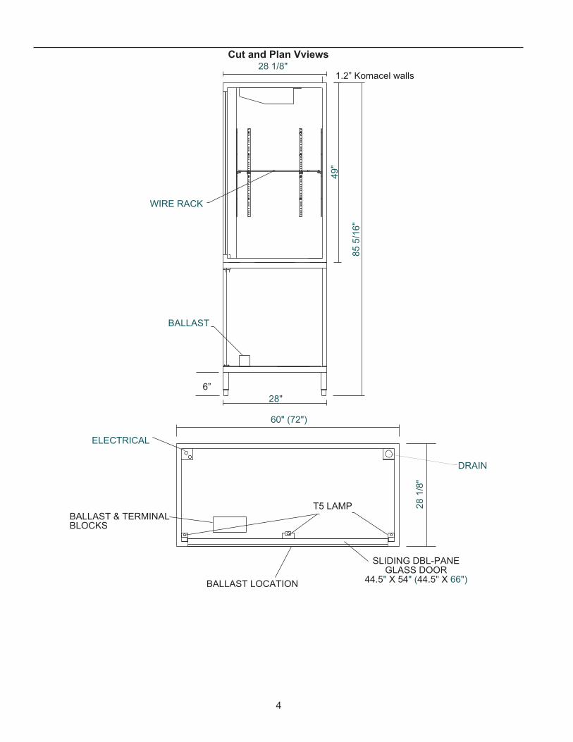
Cut and Plan vviews
WIRE RACK
BALLAST
28 1/8"
85 5
/16"
49"
28"
BALLAST & TERMINALBLOCKS
T5 LAMP
DRAIN
SLIDING DBL-PANEGLASS DOOR
44.5" X 54" (44.5" X 66")BALLAST LOCATION
ELECTRICAL
6”
1.2” Komacel walls
28 1
/8"
60" (72")
5
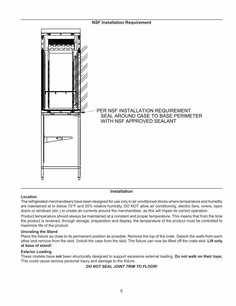
PER NSF INSTALLATION REQUIREMENT SEAL AROUND CASE TO BASE PERIMETER WITH NSF APPROVED SEALANT
InstallationLocationThe refrigerated merchandisers have been designed for use only in air conditioned stores where temperature and humidity are maintained at or below 75°F and 55% relative humidity. DO NOT allow air conditioning, electric fans, ovens, open doors or windows (etc.) to create air currents around the merchandiser, as this will impair its correct operation.Product temperature should always be maintained at a constant and proper temperature. This means that from the time the product is received, through storage, preparation and display, the temperature of the product must be controlled to maximize life of the product.Uncrating the StandPlace the fixture as close to its permanent position as possible. Remove the top of the crate. Detach the walls from each other and remove from the skid. Unbolt the case from the skid. The fixture can now be lifted off the crate skid. Lift only at base of stand!Exterior LoadingThese models have not been structurally designed to support excessive external loading. Do not walk on their tops; This could cause serious personal injury and damage to the fixture.
DO NOT SEAL JOINT TRIM TO FLOOR!
nSF Installation Requirement
6
Plumbing
Waste Outlet and P-TRAPThe waste outlet is located off the center of the case on one side allowing drip piping to be run lengthwise under the fixture.A P-TRAP must be installed to prevent air leakage and insect entrance into the fixture. (P-TRAPS are not supplied with these cases.)nOTE: PvC-DWv solvent cement is recommended. Follow the manufacturer’s instructions.Installing Condensate DrainPoorly or improperly installed condensate drains can seriously interfere with the operation of this refrigerator, and result in costly maintenance and product losses. Please follow the recommendations listed below when installing condensate drains to insure a proper installation:
1. Never use pipe for condensate drains smaller than the nominal diameter of the pipe or P-TRAP supplied with the case.
2. When connecting condensate drains, the P-TRAP must be used as part of the condensate drain to prevent air leakage or insect entrance. Store plumbing system floor drains should be at least 14” off the center of the case to allow use of the P-TRAP pipe section. Never use two water seals in series in any one line. Double P-TRAPS in series will cause a lock and prevent draining.
3. Always provide as much down hill slope (“fall”) as possible; 1/8” per foot is the preferred minimum. PVC pipe, when used, must be supported to maintain the 1/8” pitch and to prevent wraping.
4. Avoid long runs of condensate drains. Long runs make it impossible to provide the “fall” necessary for good drainage.
5. Provide a suitable air break between the flood rim of the floor drain and outlet of condensate drain. 1” is ideal.
6. Prevent condensate drains from freezing:a. Do not install condensate drains in contact with
non-insulated suction lines. Suction lines should be insulated with a nonabsorbent insulation material such as Armstrong’s Armaflex.
b. Where condensate drains are located in dead air spaces (between refrigerators or between a refrigerator and a wall), provide means to prevent freezing. The water seal should be insulated to prevent condensation.
7
Refrigerant TypeThe standard refrigerant will be R-22 unless otherwise specified on the customer order. Check the serial plate on the case for information.Refrigeration Lines
Liquid Suction3/8” O.D. 5/8” O.D.
nOTE: The standard coil is piped at 5/8” (suction); however, the store tie-in may vary depending on the number of coils and the draw the case has. Depending on the case setup, the connecting point in the store may be 5/8”, 7/8”, or 11/8”. Refer to the particular case you are hooking up.
Refrigerant lines should be sized as shown on the refrigeration legend furnished by the store.Install P-TRAPS (oil traps) at the base of all suction line vertical risers.Pressure drop can rob the system of capacity. To keep the pressure drop to a minimum, keep refrigerant line run as short as possible, using the minimum number of elbows. Where elbows are required, use long radius elbows only.Control SettingsSee the “Case Specs” section of this guidebook for the appropriate settings for your merchandiser. Maintain these parameters to achieve near constant product temperatures. Product temperature should be measured first thing in the morning, after having been refrigerated overnight. For all multiplexing, defrost should be time terminated. Load master valves are not recommended. Defrost times should as directed in the Case Specifications section of this guide. The number of defrosts per day should never change. The duration of the defrost cycle may be adjusted to meet conditions present at your location.Access to TX valves and Drain LinesMechanical - Remove product from end of case. Remove product racks. Remove refrigeration and drain access panels (labeled). TX valve (mechanical only) and drain are located under each access panel at end of the case.Electronic - The Electronic Expansion valve master and slave cylinder(s) are located within the electrical access panel(s).
Electronic Expansion valve (Optional)A wide variety of electronic expansion valves and case controllers can be utilized. Please refer to EEV and controller manufacturers information sheet. Sensors for electronic expansion valves will be installed on the coil inlet, coil outlet, and in the discharge air. (Some supermarkets require a 4th sensor in the return air). Case controllers will be located in the electrical raceway or under the case.Thermostatic Expansion valve LocationThis device is located on the same side as the refrigeration stub. A Sporlan balanced port expansion valve model is furnished as standard equipment, unless otherwise specified by customer.Expansion valve AdjustmentExpansion valves must be adjusted to fully feed the evaporator. Before attempting any adjustments, make sure the evaporator is either clear or very lightly covered with frost, and that the fixture is within 10°F of its expected operating temperature.Measuring the Operating Superheat
1. Determine the suction pressure with an accurate pressure gauge at the evaporator outlet.
2. From a refrigerant pressure temperature chart, determine the saturation temperature at the observed suction pressure.
3. Measure the temperature of the suction gas at the thermostatic remote bulb location.
4. Subtract the saturation temperature obtained in step No. 2 from the temperature measured in step No. 3.
3. The difference is superheat.5. Set the superheat for 5°F - 7°F.
T-STAT LocationT-Stats are located within the electrical raceway. Refer to diagram below.
BALLAST & TERMINALBLOCKS
T5 LAMP
DRAIN
BALLAST LOCATION
ELECTRICAL
Refrigeration
8
Refrigeration Datanote: This data is based on store temperature and humidity
that does not exceed 75F and 55% R.H.
AB Meat Discharge Air (F) 28Evaporator (F) 20
note: not recommended to control temp by regulating coil temp allow T-STAT to cycle and control temp.
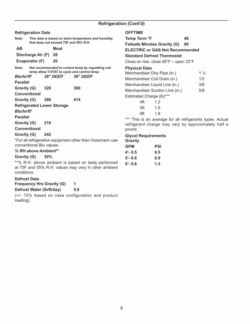
Btu/hr/ft* 28" DEEP 36" DEEPParallelGravity (G) 320 360ConventionalGravity (G) 368 414Refrigerated Lower StorageBtu/hr/ft*ParallelGravity (G) 210ConventionalGravity (G) 242*For all refrigeration equipment other than Hussmann use conventional Btu values.% RH above Ambient**Gravity (G) 30%**% R.H. above ambient is based on tests performed at 75F and 55% R.H. values may very in other ambient conditions.Defrost DataFrequency Hrs Gravity (G) 1Defrost Water (lb/ft/day) 5.8(+/- 15% based on case configuration and product loading).
OFFTIMETemp Term °F 48Failsafe Minutes Gravity (G) 90ELECTRIC or GAS not RecommendedStandard Defrost ThermostatClose on rise: close 48°F – open 33°FPhysical DataMerchandiser Drip Pipe (in.) 1 ¼Merchandiser Coil Drain (in.) 1/2Merchandiser Liquid Line (in.) 3/8Merchandiser Suction Line (in.) 5/8Estimated Charge (lb)*** 4ft 1.2 5ft 1.5 6ft 1.8*** This is an average for all refrigerants types. Actual refrigerant charge may vary by approximately half a pound.Glycol RequirementsGravityGPM PSI4’- 0.5 0.55’- 0.6 0.96’- 0.8 1.3
Refrigeration (Cont'd)
9
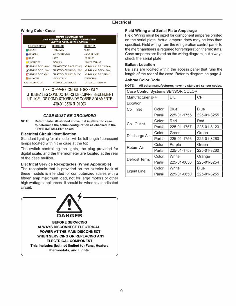
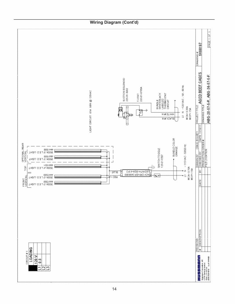
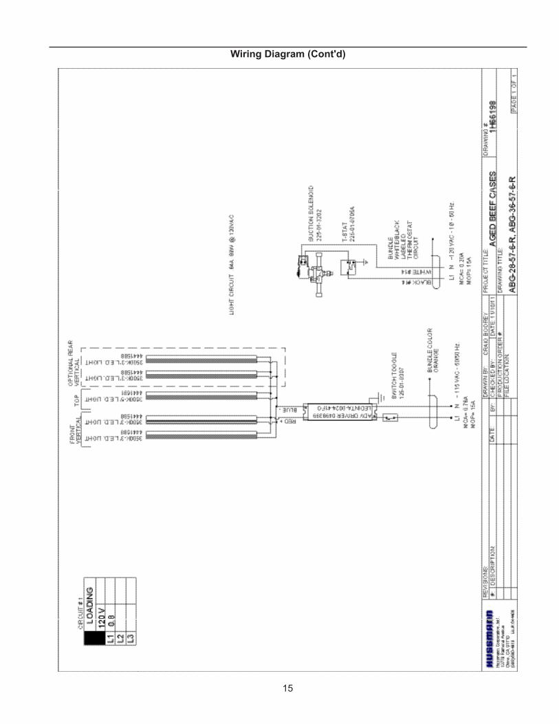
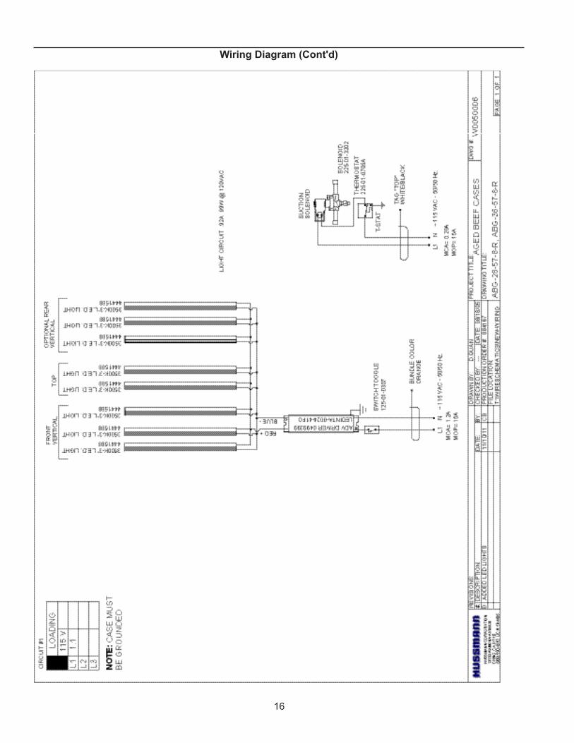
Wiring Color Code
CASE MUST BE GROUNDEDNOTE: Refer to label illustrated above that is affixed to case
to determine the actual configuration as checked in the “TYPE InSTALLED” boxes.
Electrical Circuit IdentificationStandard lighting for all models will be full length fluorescent lamps located within the case at the top.The switch controlling the lights, the plug provided for digital scale, and the thermometer are located at the rear of the case mullion.Electrical Service Receptacles (When Applicable)The receptacle that is provided on the exterior back of these models is intended for computerized scales with a fifteen amp maximum load, not for large motors or other high wattage appliances. It should be wired to a dedicated circuit.
BEFORE SERVICINGALWAYS DISCONNECT ELECTRICAL
POWER AT THE MAIN DISCONNECTWHEN SERVICING OR REPLACING ANY
ELECTRICAL COMPONENT.This includes (but not limited to) Fans, Heaters
Thermostats, and Lights.
Field Wiring and Serial Plate AmperageField Wiring must be sized for component amperes printed on the serial plate. Actual ampere draw may be less than specified. Field wiring from the refrigeration control panel to the merchandisers is required for refrigeration thermostats. Case amperes are listed on the wiring diagram, but always check the serial plate.Ballast LocationBallasts are located within the access panel that runs the length of the rear of the case. Refer to diagram on page 4.Ashrae Color CodenOTE: All other manufacturers have no standard sensor codes.
Case Control Systems SENSOR COLOR Manufacturer ® > EIL CP Location Coil Inlet
Color Blue Blue Part# 225-01-1755 225-01-3255
Coil Outlet Color Red Red Part# 225-01-1757 225-01-3123
Discharge Air Color Green Green Part# 225-01-1756 225-01-3260
Return Air Color Purple GreenPart# 225-01-1758 225-01-3260
Defrost Term. Color White OrangePart# 225-01-0650 225-01-3254
Liquid Line Color White BluePart# 225-01-0650 225-01-3255
Electrical
10
User Information
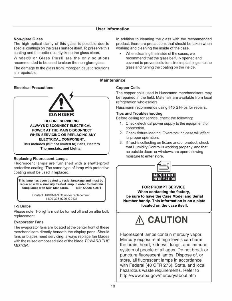
In addition to cleaning the glass with the recommended product, there are precautions that should be taken when working and cleaning the inside of the case.
• When cleaning the inside of the cases, we recommend that the glass be fully opened and covered to prevent solutions from splashing onto the glass and ruining the coating on the inside.
non-glare GlassThe high optical clarity of this glass is possible due to special coatings on the glass surface itself. To preserve this coating and the optical clarity, keep the glass clean.Windex® or Glass Plus® are the only solutions recommended to be used to clean the non-glare glass.The damage to the glass from improper, caustic solutions is irrepairable.
Maintenance
Electrical Precautions
BEFORE SERVICINGALWAYS DISCONNECT ELECTRICAL
POWER AT THE MAIN DISCONNECTWHEN SERVICING OR REPLACING ANY
ELECTRICAL COMPONENT.This includes (but not limited to) Fans, Heaters
Thermostats, and Lights.
Replacing Fluorescent LampsFluorescent lamps are furnished with a shatterproof protective coating. The same type of lamp with protective coating must be used if replaced.
This lamp has been treated to resist breakage and must be replaced with a similarly treated lamp in order to maintain
compliance with NSF Standards. NSF CODE 4.28.1
Contact HUSSMAN Chino for replacement.1-800-395-9229 X 2131
T-5 BulbsPlease note: T-5 lights must be turned off and on after bulb replacement.Evaporator FansThe evaporator fans are located at the center front of these merchandisers directly beneath the display pans. Should fans or blades need servicing, always replace fan blades with the raised embossed side of the blade TOWARD THE MOTOR.
Copper CoilsThe copper coils used in Hussmann merchandisers may be repaired in the field. Materials are available from local refrigeration wholesalers.Hussmann recommends using #15 Sil-Fos for repairs.Tips and TroubleshootingBefore calling for service, check the following:
1. Check electrical power supply to the equipment for connection.
2. Check fixture loading. Overstocking case will affect its proper operation.
3. If frost is collecting on fixture and/or product, check that Humidity Control is working properly, and that no outside doors or windows are open-allowing moisture to enter store.
FOR PROMPT SERVICEWhen contacting the factory,
be sure to have the Case Model and SerialNumber handy. This information is on a plate
located on the case itself.
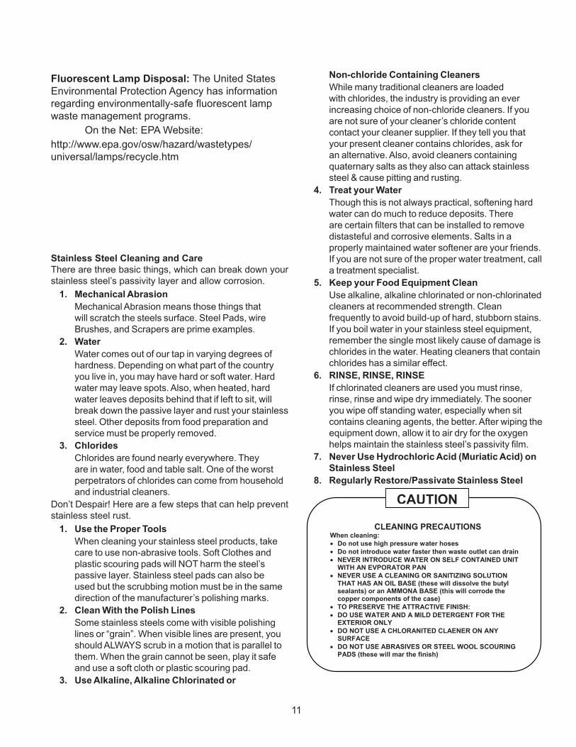
Fluorescent Lamp Disposal: The United States Envi-ronmental protection Agency has information regarding environmentally-safe fluorescent lamp waste manage-ment programs.On the Net: EPA Web site:http://www.epa.gov/osw/hazard/wastetypes/universal/lamps/recycle.htm
11
Stainless Steel Cleaning and CareThere are three basic things, which can break down your stainless steel’s passivity layer and allow corrosion.
1. Mechanical Abrasion Mechanical Abrasion means those things that
will scratch the steels surface. Steel Pads, wire Brushes, and Scrapers are prime examples.
2. Water Water comes out of our tap in varying degrees of
hardness. Depending on what part of the country you live in, you may have hard or soft water. Hard water may leave spots. Also, when heated, hard water leaves deposits behind that if left to sit, will break down the passive layer and rust your stainless steel. Other deposits from food preparation and service must be properly removed.
3. Chlorides Chlorides are found nearly everywhere. They
are in water, food and table salt. One of the worst perpetrators of chlorides can come from household and industrial cleaners.
Don’t Despair! Here are a few steps that can help prevent stainless steel rust.
1. Use the Proper Tools When cleaning your stainless steel products, take
care to use non-abrasive tools. Soft Clothes and plastic scouring pads will NOT harm the steel’s passive layer. Stainless steel pads can also be used but the scrubbing motion must be in the same direction of the manufacturer’s polishing marks.
2. Clean With the Polish Lines Some stainless steels come with visible polishing
lines or “grain”. When visible lines are present, you should ALWAYS scrub in a motion that is parallel to them. When the grain cannot be seen, play it safe and use a soft cloth or plastic scouring pad.
3. Use Alkaline, Alkaline Chlorinated or
non-chloride Containing Cleaners While many traditional cleaners are loaded
with chlorides, the industry is providing an ever increasing choice of non-chloride cleaners. If you are not sure of your cleaner’s chloride content contact your cleaner supplier. If they tell you that your present cleaner contains chlorides, ask for an alternative. Also, avoid cleaners containing quaternary salts as they also can attack stainless steel & cause pitting and rusting.
4. Treat your Water Though this is not always practical, softening hard
water can do much to reduce deposits. There are certain filters that can be installed to remove distasteful and corrosive elements. Salts in a properly maintained water softener are your friends. If you are not sure of the proper water treatment, call a treatment specialist.
5. Keep your Food Equipment Clean Use alkaline, alkaline chlorinated or non-chlorinated
cleaners at recommended strength. Clean frequently to avoid build-up of hard, stubborn stains. If you boil water in your stainless steel equipment, remember the single most likely cause of damage is chlorides in the water. Heating cleaners that contain chlorides has a similar effect.
6. RINSE, RINSE, RINSE If chlorinated cleaners are used you must rinse,
rinse, rinse and wipe dry immediately. The sooner you wipe off standing water, especially when sit contains cleaning agents, the better. After wiping the equipment down, allow it to air dry for the oxygen helps maintain the stainless steel’s passivity film.
7. never Use Hydrochloric Acid (Muriatic Acid) on Stainless Steel
8. Regularly Restore/Passivate Stainless Steel
CLEANING PRECAUTIONS When cleaning: • Do not use high pressure water hoses • Do not introduce water faster then waste outlet can drain • NEVER INTRODUCE WATER ON SELF CONTAINED UNIT
WITH AN EVPORATOR PAN • NEVER USE A CLEANING OR SANITIZING SOLUTION
THAT HAS AN OIL BASE (these will dissolve the butyl sealants) or an AMMONA BASE (this will corrode the copper components of the case)
• TO PRESERVE THE ATTRACTIVE FINISH: • DO USE WATER AND A MILD DETERGENT FOR THE
EXTERIOR ONLY • DO NOT USE A CHLORANITED CLAENER ON ANY
SURFACE • DO NOT USE ABRASIVES OR STEEL WOOL SCOURING
PADS (these will mar the finish)
CAUTION
Fluorescent Lamp Disposal: The United States Environmental Protection Agency has information regarding environmentally-safe fluorescent lamp waste management programs. On the Net: EPA Website:http://www.epa.gov/osw/hazard/wastetypes/universal/lamps/recycle.htm
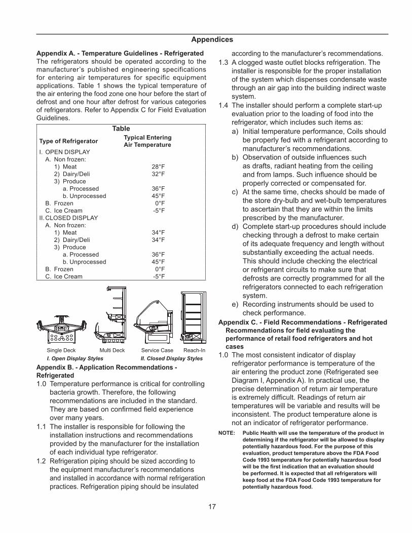
Appendix A. - Temperature Guidelines - RefrigeratedThe refrigerators should be operated according to the manufacturer’s published engineering specifications for entering air temperatures for specific equipment applications. Table 1 shows the typical temperature of the air entering the food zone one hour before the start of defrost and one hour after defrost for various categories of refrigerators. Refer to Appendix C for Field Evaluation Guidelines.
Table
Type of Refrigerator Typical Entering Air Temperature
I. OPEN DISPLAY A. Non frozen: 1) Meat 28°F 2) Dairy/Deli 32°F 3) Produce a. Processed 36°F b. Unprocessed 45°F B. Frozen 0°F C. Ice Cream -5°FII. CLOSED DISPLAY A. Non frozen: 1) Meat 34°F 2) Dairy/Deli 34°F 3) Produce a. Processed 36°F b. Unprocessed 45°F B. Frozen 0°F C. Ice Cream -5°F
Single Deck Multi Deck Service Case Reach-In I. Open Display Styles II. Closed Display Styles
Appendix B. - Application Recommendations - Refrigerated1.0 Temperature performance is critical for controlling
bacteria growth. Therefore, the following recommendations are included in the standard. They are based on confirmed field experience over many years.
1.1 The installer is responsible for following the installation instructions and recommendations provided by the manufacturer for the installation of each individual type refrigerator.
1.2 Refrigeration piping should be sized according to the equipment manufacturer’s recommendations and installed in accordance with normal refrigeration practices. Refrigeration piping should be insulated
according to the manufacturer’s recommendations.1.3 A clogged waste outlet blocks refrigeration. The
installer is responsible for the proper installation of the system which dispenses condensate waste through an air gap into the building indirect waste system.
1.4 The installer should perform a complete start-up evaluation prior to the loading of food into the refrigerator, which includes such items as: a) Initial temperature performance, Coils should
be properly fed with a refrigerant according to manufacturer’s recommendations.
b) Observation of outside influences such as drafts, radiant heating from the ceiling and from lamps. Such influence should be properly corrected or compensated for.
c) At the same time, checks should be made of the store dry-bulb and wet-bulb temperatures to ascertain that they are within the limits prescribed by the manufacturer.
d) Complete start-up procedures should include checking through a defrost to make certain of its adequate frequency and length without substantially exceeding the actual needs. This should include checking the electrical or refrigerant circuits to make sure that defrosts are correctly programmed for all the refrigerators connected to each refrigeration system.
e) Recording instruments should be used to check performance.
Appendix C. - Field Recommendations - RefrigeratedRecommendations for field evaluating the performance of retail food refrigerators and hot cases
1.0 The most consistent indicator of display refrigerator performance is temperature of the air entering the product zone (Refrigerated see Diagram I, Appendix A). In practical use, the precise determination of return air temperature is extremely difficult. Readings of return air temperatures will be variable and results will be inconsistent. The product temperature alone is not an indicator of refrigerator performance.
nOTE: Public Health will use the temperature of the product in determining if the refrigerator will be allowed to display potentially hazardous food. For the purpose of this evaluation, product temperature above the FDA Food Code 1993 temperature for potentially hazardous food will be the first indication that an evaluation should be performed. It is expected that all refrigerators will keep food at the FDA Food Code 1993 temperature for potentially hazardous food.
18
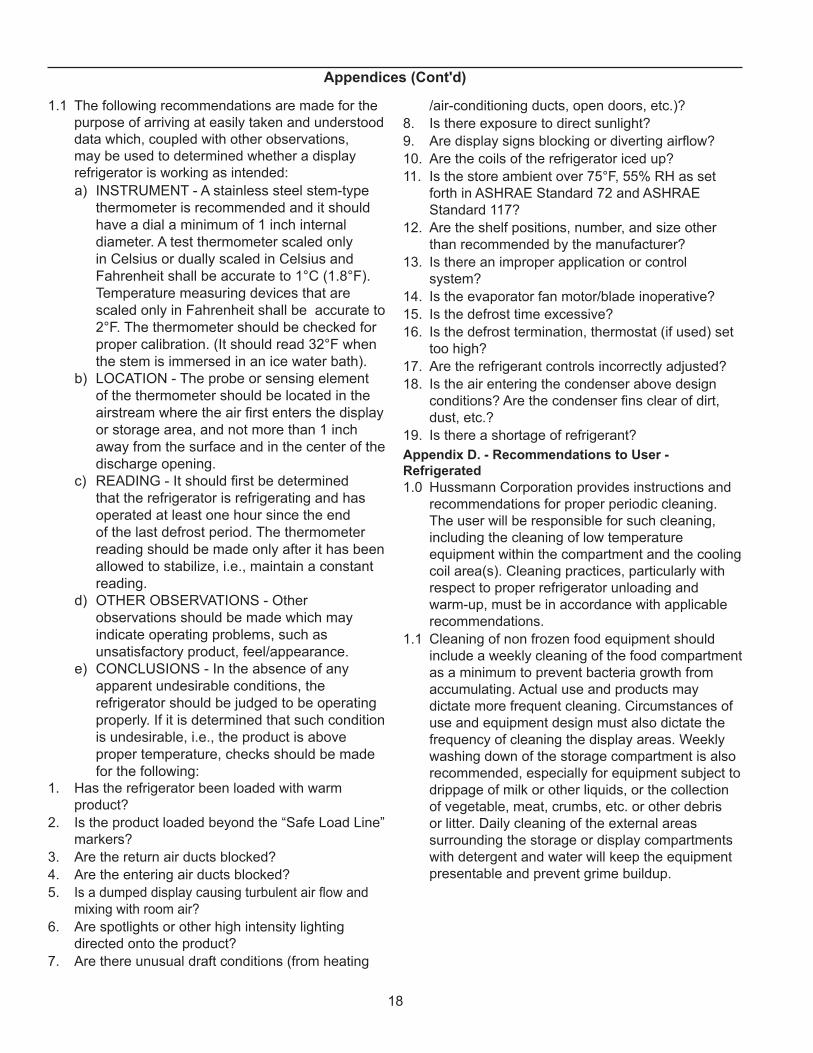
1.1 The following recommendations are made for the purpose of arriving at easily taken and understood data which, coupled with other observations, may be used to determined whether a display refrigerator is working as intended:a) INSTRUMENT - A stainless steel stem-type
thermometer is recommended and it should have a dial a minimum of 1 inch internal diameter. A test thermometer scaled only in Celsius or dually scaled in Celsius and Fahrenheit shall be accurate to 1°C (1.8°F). Temperature measuring devices that are scaled only in Fahrenheit shall be accurate to 2°F. The thermometer should be checked for proper calibration. (It should read 32°F when the stem is immersed in an ice water bath).
b) LOCATION - The probe or sensing element of the thermometer should be located in the airstream where the air first enters the display or storage area, and not more than 1 inch away from the surface and in the center of the discharge opening.
c) READING - It should first be determined that the refrigerator is refrigerating and has operated at least one hour since the end of the last defrost period. The thermometer reading should be made only after it has been allowed to stabilize, i.e., maintain a constant reading.
d) OTHER OBSERVATIONS - Other observations should be made which may indicate operating problems, such as unsatisfactory product, feel/appearance.
e) CONCLUSIONS - In the absence of any apparent undesirable conditions, the refrigerator should be judged to be operating properly. If it is determined that such condition is undesirable, i.e., the product is above proper temperature, checks should be made for the following:
1. Has the refrigerator been loaded with warm product?
2. Is the product loaded beyond the “Safe Load Line” markers?
3. Are the return air ducts blocked?4. Are the entering air ducts blocked?5. Is a dumped display causing turbulent air flow and
mixing with room air?6. Are spotlights or other high intensity lighting
directed onto the product?7. Are there unusual draft conditions (from heating
/air-conditioning ducts, open doors, etc.)?8. Is there exposure to direct sunlight?9. Are display signs blocking or diverting airflow?10. Are the coils of the refrigerator iced up?11. Is the store ambient over 75°F, 55% RH as set
forth in ASHRAE Standard 72 and ASHRAE Standard 117?
12. Are the shelf positions, number, and size other than recommended by the manufacturer?
13. Is there an improper application or control system?
14. Is the evaporator fan motor/blade inoperative?15. Is the defrost time excessive?16. Is the defrost termination, thermostat (if used) set
too high?17. Are the refrigerant controls incorrectly adjusted?18. Is the air entering the condenser above design
conditions? Are the condenser fins clear of dirt, dust, etc.?
19. Is there a shortage of refrigerant?Appendix D. - Recommendations to User - Refrigerated1.0 Hussmann Corporation provides instructions and
recommendations for proper periodic cleaning. The user will be responsible for such cleaning, including the cleaning of low temperature equipment within the compartment and the cooling coil area(s). Cleaning practices, particularly with respect to proper refrigerator unloading and warm-up, must be in accordance with applicable recommendations.
1.1 Cleaning of non frozen food equipment should include a weekly cleaning of the food compartment as a minimum to prevent bacteria growth from accumulating. Actual use and products may dictate more frequent cleaning. Circumstances of use and equipment design must also dictate the frequency of cleaning the display areas. Weekly washing down of the storage compartment is also recommended, especially for equipment subject to drippage of milk or other liquids, or the collection of vegetable, meat, crumbs, etc. or other debris or litter. Daily cleaning of the external areas surrounding the storage or display compartments with detergent and water will keep the equipment presentable and prevent grime buildup.
Appendices (Cont'd)
19
1.2 Load levels as defined by the manufacturer must be observed.
1.3 The best preservation is achieved by following these rules:a) Buy quality products.b) Receive perishables from transit equipment
at the ideal temperature for the particular product.
c) Expedite perishables to the store’s storage equipment to avoid unnecessary warm-up and prolonged temperature recovery. Food store refrigerators are not food chillers nor can they reclaim quality lost through previous mishandling.
d) Care must be taken when cross merchandising products to ensure that potentially hazardous vegetable products are not placed in non refrigerated areas.
e) Display and storage equipment doors should be kept closed during periods of inactivity.
f) Minimize the transfer time of perishables from storage to display.
g) Keep meat under refrigeration in meat cutting and processing area except for the few moments it is being handled in processing. When a cut or tray of meat is not to be worked on immediately, the procedure should call for returning it to refrigeration.
h) Keep tools clean and sanitized. Since mechanical equipment is used for fresh meat processing, all such equipment should be cleaned at least daily and each time a different kind of meat product comes in contact with the tool or equipment.
i) Make sure that all refrigeration equipment is installed and adjusted in strict accordance with the manufacturer’s recommendations.
j) See that all storage and refrigeration equipment is kept in proper working order by routine maintenance.
Appendices (Cont'd)
For further technical information, please log on to http://www.hussmann.com/products/AB.htm
20
The MODEL NAME and SERIAL NUMBER is required in order to provide you with the correct parts and information for your particular unit.They can be found on a small metal plate on the unit.Please note them below for future reference.
MODEL:
SERIAL nUMBER:
/ChinoAdditional copies of this publication may be obtained by contacting:Hussmann® Chino 13770 Ramona Avenue • Chino, California 91710(909) 628-8942 FAX(909) 590-4910 (800) 395-9229