82
CHLOROMAT - 9184 - TFC/pH version Instruction manual 03/2001 621=191=184 st Issue C

CHLOROMAT
- 9184 -
TFC/pH version
Instruction manual
03/2001 621=191=184st
Issue C

CHLOROMAT - 9184 -
This instrument conforms to the European Directives :
- 89/336/CEE modified by the directive 93/68/CEE- 73/23/CEE modified by directive 93/68/CEE
Warning!
There are no user-serviceable parts in either the transmitter or sensor. Only Polymetronpersonnel or their authorized representative should attempt repair of the system and onlycomponents expressly approved by the manufacturer should be used. Any attempt to repair theinstrument in contradiction of these guidelines may result in damage to the instrument and injury tothe person making the repair. It will also void the warranty and may compromise the safe operation,electrical integrity or CE compliance of the instrument.

CHLOROMAT - 9184 -
iii
Changing the programming language
The programming language is English when factory-programmed, when changing thesoftware version and when loading the default values. To change the language followthe procedure below (example for the French language) :

CHLOROMAT - 9184 -
iv
Programming the feed frequency
Once you chose the programming language, you can operate a change in the circuit feedfrequency if necessary. A proper configuration of the circuit feed frequency enables to obtaina better stability of the analog to digital converter and therefore of your measures. Operate thischange the first time you charge the analyser - follow the hereunder procedure :

CHLOROMAT 9184
1-1
Chapter 1 : Introduction
1.1 Introduction
Chloromat 9184 TFC/pH version is an industrial analyzer for on-line selective measurement offree chlorine (HOCl + ClO ) in the field of drinking water treatment plants, distribution networks-
and any other application that requires free chlorine follow-up in the range of ppb and ppm.Measurement is done by an amperometric cell after the molecules diffused through amembrane.
1.2 About chlorine
Specific terms exist to mention the different species of chlorine :
- Active chlorine HOCl (hypochlorous acid)It is the most powerful disinfectant, up to 100 times more efficient than hypochlorite (seehereunder)
- Total Free Chlorine (TFC) : HOCl + ClO :-
It is composed of gaseous chlorine (at low pH values), hypochlorous acid HOCl andhypochlorite ion ClO . These species coexist, their relative proportion depending on pH and-
temperature (see curve below for a 25°C temperature).
- Total combinated chlorine (TCC) :It results from the addition of free chlorine plus chloramines (mono-, di- and trichloramine).
Fraction of Cl , HOCl and ClO react as a function of pH : :2-

CHLOROMAT 9184
1-2
The dissociation reactions are as follow :
Cl + H O ÷ H + Cl + HOCl pK1 = 4.6 at 25°C2 2+ -
HOCl ÷H + ClO pK2 = 7.5 at 25°C+ -
It is also important to notice that the dissociation constants are temperature-dependent.
1.3 Measuring principles
Active chlorine measure lies on the Clark cell principle.The sensor - amperometric type - is composed of :
- one gold working electrode where the main reaction occurs,- one silver counter-electrode which is also used as a reference electrode,- a potassium chloride-based electrolyte,- one microporous membrane selective to HOCl :
1 : Electrode 6 : Membrane holder
2 : Electrolyte 7 : Membrane
3 : Probe body 8 : Cathode
4 : Filling-in hole 9 :Membrane/sample interface
5 : Anode 10 : Sample
The HOCl molecules contained in the sample diffuse through the membrane. HOCl is then

CHLOROMAT 9184
1-3
located in a thin electrolyte layer, between the membrane and the cathode.A constant working potential is applied to the working electrode (cathode) where HOCl isreduced :
HOCl + H + 2e ÷ Cl + H O+ - -2
At the silver electrode (anode), silver is oxidised into Ag ions which then precipitate with the+
chloride ions :
2Cl + 2Ag ÷ 2AgCl + 2e- -
HOCl reduction at the cathode generates a current directly proportional to itsconcentration.
The electrochemical reaction and the diffusion through the membrane depend on temperature.The measuring cell is therefore equipped with a temperature sensor which enables to operatean automatic compensation of the measurement.
1.2 Main characteristics
3 Measuring range 0 to 5 mg/l
3 Temperature compensation
3 Programmable alarm levels, outputs on relays
3 4-20 mA, 0-20 mA outputs, standard alarm levels and RS485 (option)

CHLOROMAT 9184
1-4
1.3 Technical characteristics
SAMPLE
Number of channels 1
Temperature 0-45°C (32-113°F)
Working pressure 0.1-2 bar (1.4-29 psi)
Flow 10-30 l/h (12-15 l/h recommended)
ELECTRICAL CHARACTERISTICS
Mains 100...240 VAC, 50/60 Hz
Power consumption 25 VA
Fuse 5x20 T2AL - 250 v
Mounting on wall, panel, tube
ANALYSIS
Measured species TFC and HOCl
Measuring range 0-5 mg/l
Repeatability HOCl : < ±2% of the measurement or < ± 5 ppbFree chlorine :if pH < 7.5, < ± 5% of the measurement or < ± 10ppbif pH < 8.0, < ± 10% of the measurement or < ±20 ppbif pH > 8.0, < ± 15% of the measurement or < ±30 ppb
Detection limit < 10 ppb HOCl~ 20 ppb free chlorine
Response time (90 %) < 90s
Ambient temperature 0-45°C, +32-+113°F
Interference Ozone, chlorine dioxide. No interference from thechloramines
Units µA, ppb-µg/l, ppb-mg/l, °C, °F
Calibration Electrical zero, chemical zero, process slopecalibration by comparison with a laboratorymeasurement
CHLOROMAT 9184
1-5
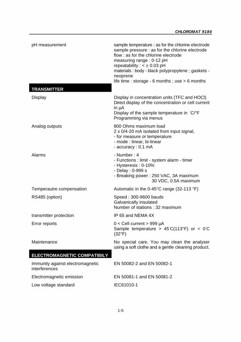
pH measurement sample temperature : as for the chlorine electrodesample pressure : as for the chlorine electrodeflow : as for the chlorine electrodemeasuring range : 0-12 pHrepeatability : < ± 0.03 pHmaterials : body - black polypropylene ; gaskets -neoprenelife time : storage - 6 months ; use > 6 months
TRANSMITTER
Display Display in concentration units (TFC and HOCl)Direct display of the concentration or cell currentin µADisplay of the sample temperature in C/°F B
Programming via menus
Analog outputs 800 Ohms maximum load2 x 0/4-20 mA isolated from input signal,- for measure or temperature- mode : linear, bi-linear- accuracy : 0.1 mA
Alarms - Number : 4- Functions : limit - system alarm - timer- Hysteresis : 0-10%- Delay : 0-999 s- Breaking power : 250 VAC, 3A maximum 30 VDC, 0.5A maximum
Temperautre compensation Automatic in the 0-45°C range (32-113 °F)
RS485 (option) Speed : 300-9600 baudsGalvanically insulatedNumber of stations : 32 maximum
transmitter protection IP 65 and NEMA 4X
Error reports 0 < Cell current > 999 µASample temperature > 45 C(113°F) or < 0 CB B
(32°F)
Maintenance No special care. You may clean the analyserusing a soft clothe and a gentle cleaning product.
ELECTROMAGNETIC COMPATIBILY
Immunity against electromagnetic EN 50082-2 and EN 50082-1interferences
Electromagnetic emission EN 50081-1 and EN 50081-2
Low voltage standard IEC61010-1

CHLOROMAT 9184
1-6
MATERIALS
Working electrode Gold cathode
Counter-electrode Silver anode
Membrane body PVC
Membrane PTFE
Transmitter Aluminium + polyester painting
Probe body PVC
MAINTENANCE
Approximative lifetime of the between 1 and 6 months depending on samplemembrane
ENVIRONMENTAL CONDITIONS
Room temperature -20 to +60°C
RH 10 to 90%

CHLOROMAT - 9184 -
2-1
Chapter 2 : Description of the analyser
Figure 2.1 : synoptic of the instrument
1 : chlorine cell input fitting (for 4x6 mm 9 : chlorine cell taptube)
2 : flow-through cell 10 : pH cell input fitting ( 4x6 mm tube)
3 : chlorine cell output fitting (for 6x8 11 : pH flow-through cellmm tube)
4 : membrane 12 : pH cell output fitting (for 4x6 mmtube)
5 : probe body 13 : gasket
6 : electrolyte filling plug 14 : pH probe
7 : electrode 15 : pH cell tap
8 : fastening nut

CHLOROMAT - 9184 -
2-2
2.1 Hydraulics
2.1.1 Mounting the chlorine cell
(Dimensions are in mm [inches])
1 : Probe 3 : 1/4" NPT fitting for 6x8 mm tube
2 : Cell 4 :1/4" NPT fitting for 4x6 mm tube

CHLOROMAT - 9184 -
2-3
2.1.2 Mounting the pH cell
1 : pH cell
2 : mounting holes (ii 4 mm max screw, 25 mm length as aminimum)
3 : input fitting (for 4x6 mm tube)
4 : output fitting (for 4x6 mm tube)

CHLOROMAT - 9184 -
2-4
2.1.3 Using the mounting plate (in option)
mounting plate 09184=C=2700 (in option)

CHLOROMAT - 9184 -
2-5
2.1.4 Mounting plate + overflow vessel in option
This option enables to have a constant flow through the cells - about 15 l/h.
1 : mounting plate 09184=C=2700
2 : overflow vessel 09184=A=1700
3 : overflow vessel outlet, pH cell feed
4 : sample inlet ( 4x6 mm tube)
5 : overflow drain ( 12x17 mm tube)

CHLOROMAT - 9184 -
2-6
2.1.5 Mounting plate (option) + control valve (in option)
This option enables to adjust the flow to the recommended values (12-15 l/h).
Front view Back view
1 : mounting plate 09184=C=2700
2 : flow adjustement valve 696=046=001
3 : sample inlet 4x6 mm
4 : outlet tube 6x8 mm

CHLOROMAT - 9184 -
2-7
2.1.6 Simultaneous mounting of options
You may also combine the valve + overflow vessel options in order to stabilise theflow (~ 15 l/h) whatever may be the changes in incoming pressures (from 0 to 7 bars).
1 : mounting plate 09184=C=2700
2 : flow adjustment valve 696=046=001
3 : overflow vessel 09184=A=1700
4 : overflow drain ( 12x17 mm tube)
5 : sample inlet (4x6 mm tube)
6 : outlet tube (6x8 mm tube)
CHLOROMAT - 9184 -
2-8
2.2 Transmitter
2.2.1 Presentation of the transmitter
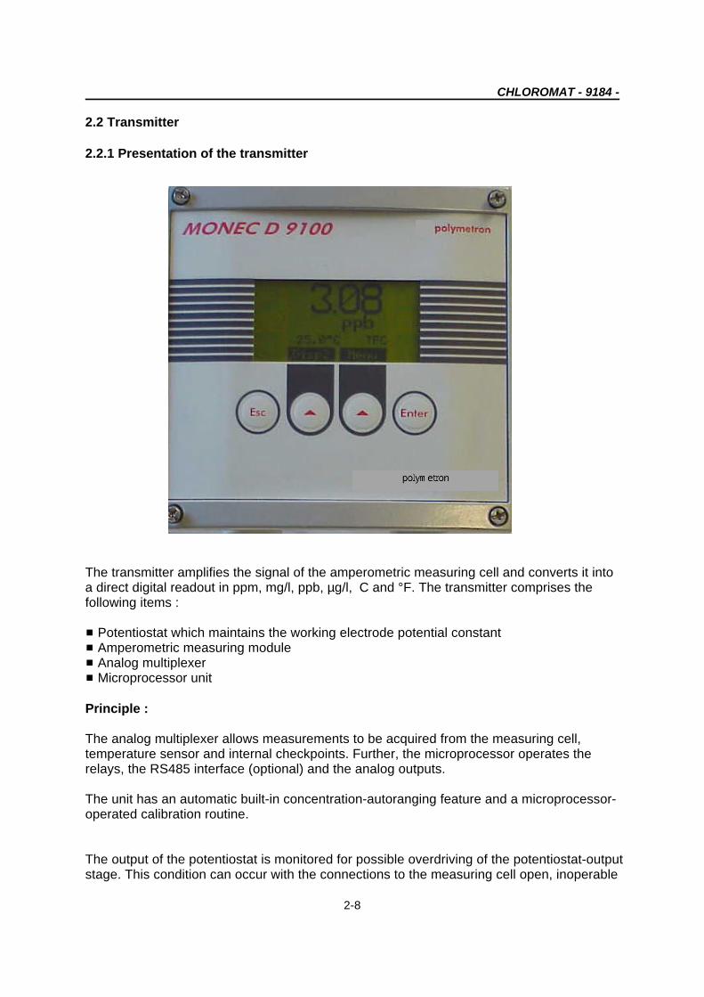
The transmitter amplifies the signal of the amperometric measuring cell and converts it intoa direct digital readout in ppm, mg/l, ppb, µg/l, C and °F. The transmitter comprises theB
following items :
# Potentiostat which maintains the working electrode potential constant# Amperometric measuring module# Analog multiplexer# Microprocessor unit
Principle :
The analog multiplexer allows measurements to be acquired from the measuring cell,temperature sensor and internal checkpoints. Further, the microprocessor operates therelays, the RS485 interface (optional) and the analog outputs.
The unit has an automatic built-in concentration-autoranging feature and a microprocessor-operated calibration routine.
The output of the potentiostat is monitored for possible overdriving of the potentiostat-outputstage. This condition can occur with the connections to the measuring cell open, inoperable

CHLOROMAT - 9184 -
2-9
electrodes or a defective reference electrode.
Transmitter synoptic is as follows :
1 : Programmable potentiostat 6 : Auxiliary input
2 : Polarization voltage amplifier 7 : Multiplexer
3 : Reversing switch to use 2 or 3 8 : A/D converterelectrodes
4 : Temperature measurement circuit 9 : Microprocessor
5 : Measurement circuit current amplifier

CHLOROMAT - 9184 -
2-10
2.2.2 Dimensions of the transmitter
Dimensions are in mm and [inches].
2.2.3 Application fields
Easy-to-use, (installation, programming), this microprocessor unit can be used for different applications, such as :
- drinking water treatment- distribution networks monitoring
2.2.4 Possibilities to mount the transmitter in standard (using the red clamping bow)
The enclosure is in conformity with the DIN 43700 standard.
CHLOROMAT - 9184 -
2-11
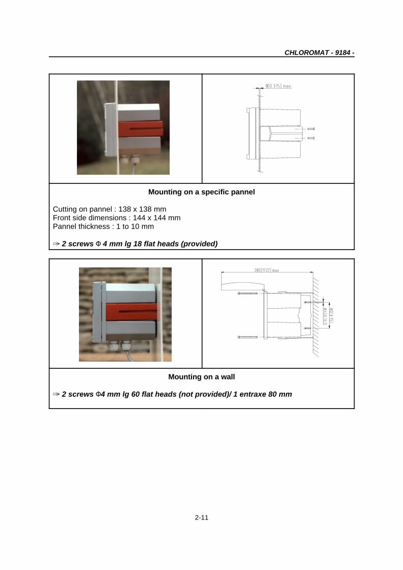
Mounting on a specific pannel
Cutting on pannel : 138 x 138 mmFront side dimensions : 144 x 144 mmPannel thickness : 1 to 10 mm
R 2 screws M 4 mm lg 18 flat heads (provided)
Mounting on a wall
R 2 screws M4 mm lg 60 flat heads (not provided)/ 1 entraxe 80 mm

CHLOROMAT - 9184 -
2-12
Vertical mounting on tubeR M 2" maximum - 2 screws M 4 mm lg 60(supplied)
Horizontal mounting on tube R M 2" maximum - 2 screws M 4 mm lg 60(supplied)

CHLOROMAT - 9184 -
3-1
Chapter 3 : Installation of the instrument
3.1 Unpacking 3.3 Mounting and connections
The analyzer should be unpacked with greatcare. Make sure not to loose any accessorywhen unpacking.
3.2 Inspection
The analyzer has been factory-checked andtested prior to shipment, it is howeveradvisable to inspect all parts immediatelyupon receipt for any damage which mayhave occured during shipment. A damagedshipping container may indicate internaldamage which may not be immediatelyobvious. If there is any evidence of damage,keep the shipping container and refer toyour local agent or to :
Polymetron S.A.Z.I. des Richardets33, rue du Ballon
93160 NOISY-LE-GRAND
CAUTION !
Mounting should be done byqualified service personnel only. Nopower supply should be applieduntil the installation is completedand checked.
3.4 Location
The analyzer should be installed in anaccessible location.
It should permit the access for any checkingor maintenance operation.
Sample flow should meet the analyserspecifications.

P1 contrast adjustment
Microprocessor board
Relay board
Power supply boardAmperometric board
RS485 board (option)
Programmed memory
CHLOROMAT - 9184 -
3-2
3.5 Electric connections
33 MONEC
Do not switch on the instrument until completion of the installation.
An aluminium shielding plate inside the MONEC gives a detailed description of the differentterminals and their connections to external elements :
L The different terminals represented on the right side are accessible by removing the shieldingplate.
CHLOROMAT - 9184 -
3-3
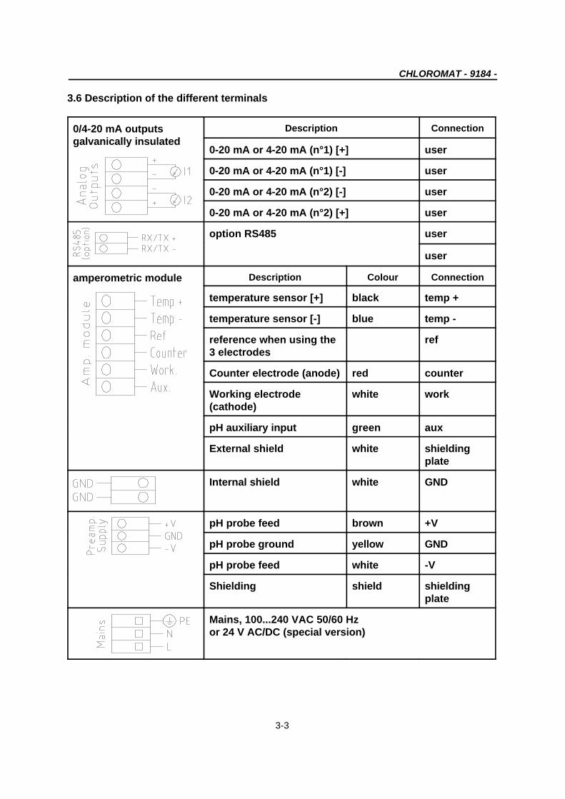
3.6 Description of the different terminals
0/4-20 mA outputsgalvanically insulated
Description Connection
0-20 mA or 4-20 mA (n°1) [+] user
0-20 mA or 4-20 mA (n°1) [-] user
0-20 mA or 4-20 mA (n°2) [-] user
0-20 mA or 4-20 mA (n°2) [+] user
option RS485 user
user
amperometric module Description Colour Connection
temperature sensor [+] black temp +
temperature sensor [-] blue temp -
reference when using the ref3 electrodes
Counter electrode (anode) red counter
Working electrode white work(cathode)
pH auxiliary input green aux
External shield white shieldingplate
Internal shield white GND
pH probe feed brown +V
pH probe ground yellow GND
pH probe feed white -V
Shielding shield shieldingplate
Mains, 100...240 VAC 50/60 Hzor 24 V AC/DC (special version)

CHLOROMAT - 9184 -
3-4
Description connection
alarm 1, simple contact user
alarm 2, simple contact user
alarm 3 or system alarm, simple contact user
alarm 4 or timer, simple contact user
3.6.1 Electric connections of the TFC and pH probes :

CHLOROMAT - 9184 -
3-5
3.7 Mains connection
Electrical connection should be performed only by qualified personnel. The power supplyaccepts 100-240 VAC ± 10 %, (50/60 Hz) without changes in configuration. The terminal blockfor power connections can be lifted from its header for easier installation. For safety reasons,it is required to observe the precautions below :
! Use a three core mains supply cord (2 core + PE) rated for the maximum equipmentcurrent
! The instrument should be connected to the power supply by means of a breaker locatedclose to the instrument and be identified. The supply shall be fitted with an overcurrentprotection device rated at 20 Amp maximum
! This breaker should switch off phase and neutral in case of electrical problems or whenthe user wish to service the instrument. However the power supply earth must alwaysbe connected.
Before servicing the instrument, ensure that the power supply is switched off.
3.8 Starting the transmitter
Before switching on the transmitter, make sure the site voltage corresponds to the instrumentvoltage indicated on the identification plate.
3.9 Adjusting the display contrast
If the contrast on the display screen is not sufficient, you can adjust it with the potentiometer P1(blue colour, see figure on page 3-2) which is located on the left top of the CPU board (afteropening the enclosure).

CHLOROMAT - 9184 -
4-1
Chapter 4 : Using the instrument
4.1 Front panel keys
The display may be programmed to indicate :
# Sample concentration# Sample temperature# Diffusion current# Access codes# Programming arguments
Figure 4-1 : Front panel

CHLOROMAT - 9184 -
4-2
4.2 Display screens 1 to 4 (continuously refreshed)
6.59 ppb : concentration measurement(ppb unit)23.2°C : temperature measurementTFC : applicationS1...S4 : alarm status (invisible if alarminactive).
Display of the measurementparameters :TFC concentrationHOCl concentrationTemperatureCell currentSample pH
S1...S4 : alarm statusIn this case relays S1 and S3 areactivated.
Analog output assignment and level

CHLOROMAT - 9184 -
4-3
4.3 Description of the function keys
The function keys below have their signification highlighted at the bottom of the screen :
4.4 Icons
Symbol of waiting or instrument reset
System alarm for relay S3
Timer symbol : countdown

CHLOROMAT - 9184 -
4-4
4.5 Enter or modify a value
The highlighted digit can be modified with the key.Each digit can be validated by prssing ENTER. Repeat both operations for each digit.Example :
4.6 Warnings
Note 1 : If you do not use the keyboard for at least 10 minutes, the instrument returns to themeasuring mode.
Note 2 : An access code may be required for the calibration, programming and servicemenu (see § CODE menu).
Possibility to display a negative first digit “-”Possibility to display a “.” for the other digits.
CHLOROMAT - 9184
5-1
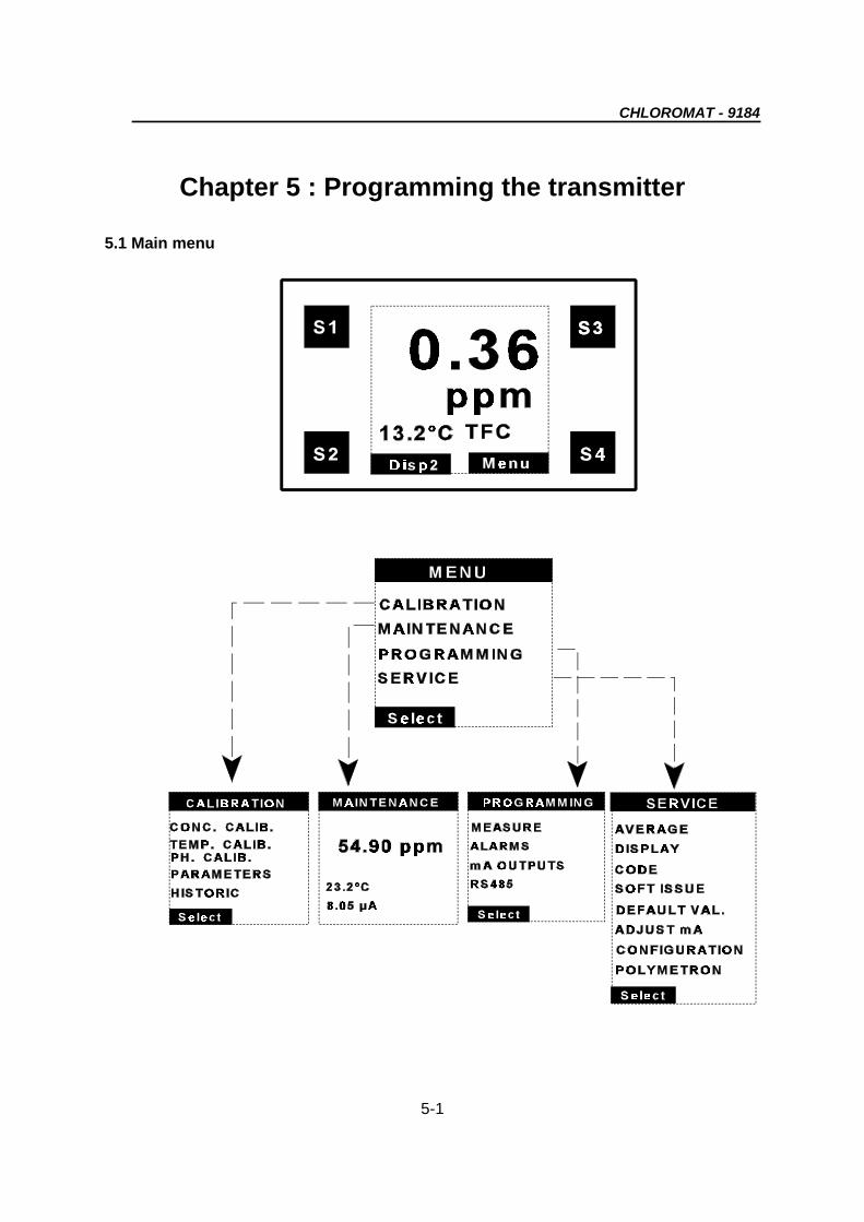
Chapter 5 : Programming the transmitter
5.1 Main menu

HISTORICPARAMETERS
SLOPE
DATE: 01/01/98
P: 1.000µA/ppm
))T: 0.0 °C
ZERO
CONC. CALIB.
DATE: 07/12/98P: 427.6µA/ppmDATE: 01/01/98P: 430.5µA/ppm
TEMP CALIB
EXECUTION EXECUTION
PH CALIB
CHLOROMAT - 9184
5-2
An access code may be required if it has been programmed (See §5.1.4.3CODE Menu)See chapter 6 for detailed calibration procedures.Some menus may appear or not depending on the way some parametershave been programmed.
5.1.1 CALIBRATION menu
L Any calibration should follow the procedure below :
ìì Configuration of the calibration parameters in the “PROGRAMMING” menu.
íí Calibration via the “EXECUTION” menu.
CHLOROMAT - 9184
5-3
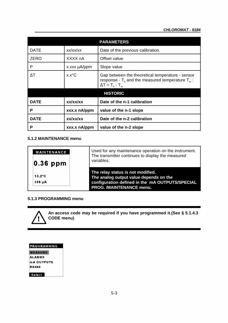
An access code may be required if you have programmed it.(See § 5.1.4.3CODE menu)
PARAMETERS
DATE xx/xx/xx Date of the previous calibration.
ZERO XXXX nA Offset value
P x.xxx µA/ppm Slope value
)T x.x°C Gap between the theoretical temperature - sensorresponse - T and the measured temperature T :h m
)T = T - Th m
HISTORIC
DATE xx/xx/xx Date of the n-1 calibration
P xxx.x nA/ppm value of the n-1 slope
DATE xx/xx/xx Date of the n-2 calibration
P xxx.x nA/ppm value of the n-2 slope
5.1.2 MAINTENANCE menu
Used for any maintenance operation on the instrument.The transmitter continues to display the measuredvariables.
The relay status is not modified.The analog output value depends on theconfiguration defined in the mA OUTPUTS/SPECIALPROG. /MAINTENANCE menu.
5.1.3 PROGRAMMING menu

CHLOROMAT - 9184
5-4
51.3.1 MEASURE menu
TEMPERATURE COMPENSATION
TYPE - Auto Choice of a temperature measurement with automatic- Manual compensation or with a manual compensation
If you have chosen a manual temperature compensation, the TEMP. CALIB. Menu is not accessible anymore.
TEMP. - xx.x°C Possibility to enter the sample temperature in amanual compensation mode
SENSOR NTC/AD590 Type of temperature sensor used on the 9184Chloromat. You have to program the NTC.
PH COMPENSATION
pH xx.xx sample pH value if the manual mode is selected
TYPE - Auto The pH sensor continuously measures the pH of the
- Manual The pH sensor is desactivated. The pH value takensample
into account for the measurement must be entered bythe user.

CHLOROMAT - 9184
5-5
5.1.3.2 ALARMS menu
Relays S1...S4 may be assigned to concentration limits, system alarm or timer functions.
55LIMIT FUNCTION :
The alarm relays are activated if the comparison of the measured value (temperature and TFCexclusively) with the programmed limit meets the alarm function condition (up or down). Limitsare programmed according to the following programming variables :
ALARMS 1 .... 4 (LIMIT)
AFFECT -Conc. Use of a limit on the measure, on the- no temperature or no use of a limit.-EC/EF
LIM xxxx Enter a limit value
DIR. -Up Choice of the direction-Down
DELAY xxxs Temporisation time before the relay isactivated (in seconds).
HYST. XX% Definition of the hysteresis limit in %(10% max.)The hysteresis operates only on oneside of the limit. The hysteresis is belowthe limit for the upward alarm andabove the limit for the downward alarm.
RELAY -NO Relay normally open or normally closed-NC

CHLOROMAT - 9184
5-6
55 SYSTEM ALARM FUNCTION :
The relay S3 can be used to indicate that a hardware problem has been detected.
The relay S3 is activated as soon as a default appears.
Under the manual acknowledgment, the relay remains activated even if the default disappears.Press ENTER to disactivate the alarm and the error message.
Under the automatic acknowledgment, the relay and the error message are desactivated as thedefault disappears.
ALARM 3 (SYSTEM ALARM)
MODE -No The alarm S3 may be programmed as a-Limit concentration limit (see paragraph above) or-Syst. as a system alarm
ACCEPT -Auto In case of system alarm functionning, choice-Manu between manual (ENTER key) or automatic
acknowledgment
RELAY -NO S3 normally open or normally closed.-NC

Open
Closed
Relay S4
Time
Ton (5 s)
TmA (5 min)
Interval (1440 min)
Toff (3 s)
Nb of impulsions (5)
CHLOROMAT - 9184
5-7
55 TIMER FUNCTION :
Relay S4 may be activated at a programmed frequency.The cycle can be programmed as follows :
ALARM 4 (TIMER)
MODE -No Choice between a limit (see parameters-Limit above) or a timer function for alarm 4.-Timer
INTERV XXXXmn Interval between 2 cycles (in minutes).
IMPUL. X Number of pulses of each cycle.
Ton XXXs Adjustment of the relay active time (inseconds) for each pulse.
Toff XXXs Adjustment of the relay inactive time (inseconds) for each pulse.
TmA XXmn Hold time for the analog outputs aftereach cycle. L The analog output status depends on theconfiguration of the menu mA - OUTPUTS/SPECIAL PROG./TIMER
Example of functioning for the Timer using the above parameters :

OUTPUT 1
AFFECT.: pH
TYPE : 4-20
MODE : Lin
OUTPUT 2
SPECIAL PROG.TEST
LOW : 0.0 pHUP: 9.0 pH
MAINTENANCE
SYST. ALARM.CALIBRATION
TIMER
MODE : Preset
VALUE : 00mA VALUE : 00 mA
CHLOROMAT - 9184
5-8
5.1.3.3 mA OUTPUTS menu
The analog output signals allow the transmission of the measurements from the analyser to anyexternal control system.
It is highly recommended to use shielded cable for the output signals, connected to the earthterminal on the shielding plate of the instrument.

CHLOROMAT - 9184
5-9
OUTPUT 1/2
AFFECT - TFC Choice of the analog output allocated to pH measurement,- HOCl HOCl or TFC concentration, or temperature.- EC/EF- pH
TYPE 0/20 Choice of the analog output type4/20
MODE - Lin Choice between a linear or dual range scale (see drawing on- Dual next page).
LOWER XXXX Bottom of the scale value
MIDD. XXXX Mid-scale value (only in dual mode)
UPPER XXXX Top of the scale value
SPECIAL PROG.
MODE - last Behaviour of the analog outputs during calibration, alarm- preset system, maintenance or timer active cycles : frozen to the- live latest measuring value, forced to a preset value, live
measurement.
VALUE XX Preset value (0 to 21 mA)
TEST Test the analog outputs by 1 mA steps (0-21 mA)
Illustration of the linear/dual outputs scales :

CHLOROMAT - 9184
5-10
5.1.3.4 RS485 Menu
If the RS485 optional board is installed on your transmitter, program the parameters of themenu below.The RS485 optional board enables the connection between your analyser and a digitalcommunication system. The Communication protocol is JBUS/MODBUS. Refer to theinstruction manual “JBUS/MODBUS communication” (part number : 621=991=000) for furtherdetails and to Appendix 4 for the addresses list.
RS485
NE XX MONEC number (0-32)
BAUD - 300 Transmission speed in baud- 600- 1200- 2400- 4800- 9600
PARITY - No Without parity bit- Odd With odd parity bit- Even With even parity bit
BIT STOP - 1 1 bit stop- 2 2 bit stop

!
AVERAGE : 9
TEST
Average
3.46 ppmReal
3.49 ppm
CHLOROMAT - 9184
5-11
An access code may be required if it has been programmed (see §5.2.4.3CODE Menu)
5.1.4 SERVICE Menu
5.1.4.1 AVERAGE Menu
The measurement cycle lasts 4 seconds.
AVERAGENNE Program a moving average on the concentration measurement
AVERAGE X Define the number of measurements to calculate the average.
TEST Displays both average and live readings to check the averagingeffect.

CONC : ppb/ppm
TEMP. : °C
LANGUAGE : F
CALIB. : 0000
PROG. : 0000
SERVICE : 0000
CHLOROMAT - 9184
5-12
5.1.4.2 DISPLAY Menu
DISPLAY
CONC - ppb/ppm Choice of the concentration unit- µg-mg/l
TEMP. - EC Choice of the temperature unit- EF
LANGUAGE Choice of the language :- F - French- GB - English- D - German- SP - Spanish- I - Italian
5.1.4.3 CODE Menu
Protection codes may be programmed to access the PROGRAMMING, CALIBRATION,SERVICE menus.
This code may be desactivated by programming 0000.

MONEC 9184
AMP 1.00
CHLOROMAT - 9184
5-13
CODE
CALIB. XXXX Access code to calibration
PROG. XXXX Access code to the “PROGRAMMING” menu
SERVICE XXXX Access code to the “SERVICE” menu
If you have forgotten your access code, press simultaneously ESC and ENTER toenter the selected menu.
5.1.4.4 SOFT VERSION Menu
This menu displays the software version installed in the instrument.
5.1.4.5 DEFAULT VAL. Menu
If you press YES, you load the default values andyou loose both the currently programmed valuesand calibration parameters.

CHLOROMAT - 9184
5-14
5.1.4.6 mA ADJUST menu
The analog output signals are factory-adjusted (upper limit : 20mA). However if you discovera drift of the 20 mA on one of the outputs, it is required to execute the menu below. Connecta micro-amperometer to the analog output terminals and adjust the value till you read 20.0mA on the amperemeter.
LL The value displayed does not correspond to a mA value.
5.1.4.7 CONFIGURATION menu
Mains supply frequency : 50 or 60Hz.
5.1.4.8 POLYMETRON menu
This menu is reserved to POLYMETRON qualifiedpersonnel.

6.87ppm
ENTER : ok
ESC : cancel
))T: 0.0 °C
EXECUTION
21.2°C
21.2°C
21.2 °C
CHLOROMAT - 9184 -
6-1
NOTESee chapter 5 for programming the commands.
Chapter 6 : Calibrating the instrument
6.1. Calibration of the temperature sensor
The temperature sensor is factory-preadjusted but needs to be calibrated in the sample on site.This calibration must be performed before the chlorine measurement calibration.
6.1.1.Automatic temperature compensation
The sensor measures continuously the sample temperature. The concentration values areautomatically calculated in function of the reference temperature (25 EEC) using apreprogrammed compensation law.Follow the procedure below :
ìì PROGRAMMING
Choice of an automatic temperaturecompensation.
íí EXECUTION
The execution is performed in theCALIBRATION/TEMP CALIB menu.
Enter the sample temperature value in °C.Press OK to adjust the temperature displayed tothe actual value measured with a precisethermometer.The gap between the calibration and thetheoretical response curve of the sensor is givenfor information.

TEMP. COMP.
TYPE : Manual
TYPE : Manual
TEMP.:25.0°C
SENSOR : NTC
SENSOR : NTC
PH. COMP.
CHLOROMAT - 9184 -
6-2
6.1.2. Manual temperature compensation
This type of temperature compensation should be used only if your water temperature isconstant.
ìì PROGRAMMING
Choice of the manual temperaturecompensation.
Enter your sample temperature.
íí EXECUTION
Not applicable under manual temperaturecompensation mode.

CHLOROMAT - 9184 -
6-3
6.2. Calibration of the measurement
Slope calibration is operated by comparison with a laboratory measurement, with a chemicalor electric zero.
6.2.1. Slope calibration + electrical zero
ìì PROGRAMMING
Choice of an electrical zero.Note : the electrical zero is carried outautomatically by the transmitter at a regularfrequency.
íí EXECUTION
Under the CALIBRATION menu, select SLOPECALIB.Press ENTER, the “CAL” message flashes andindicates the instrument is in calibrating mode.Wait until the current is stabilized then press OK.You can adjust the concentration value one digitafter the other with the function key to the valueyou found with the reference method of analysis.
The analyzer displays the date of the previouscalibration and the newly calculated slope. Modifythe date if necessary.
25.0°C
EXECUTION
5.4Ppb
5.693µA
EXECUTION
PROGRAMMING
25.0°C
0°ppm
5.693µA
CHLOROMAT - 9184 -
6-4
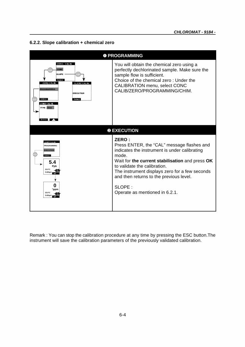
6.2.2. Slope calibration + chemical zero
ìì PROGRAMMING
You will obtain the chemical zero using aperfectly dechlorinated sample. Make sure thesample flow is sufficient.Choice of the chemical zero : Under theCALIBRATION menu, select CONCCALIB/ZERO/PROGRAMMING/CHIM.
íí EXECUTION
ZERO :Press ENTER, the “CAL” message flashes andindicates the instrument is under calibratingmode. Wait for the current stabilisation and press OKto validate the calibration.The instrument displays zero for a few secondsand then returns to the previous level.
SLOPE :Operate as mentioned in 6.2.1.
Remark : You can stop the calibration procedure at any time by pressing the ESC button.Theinstrument will save the calibration parameters of the previously validated calibration.
CHLOROMAT - 9184 -
6-5
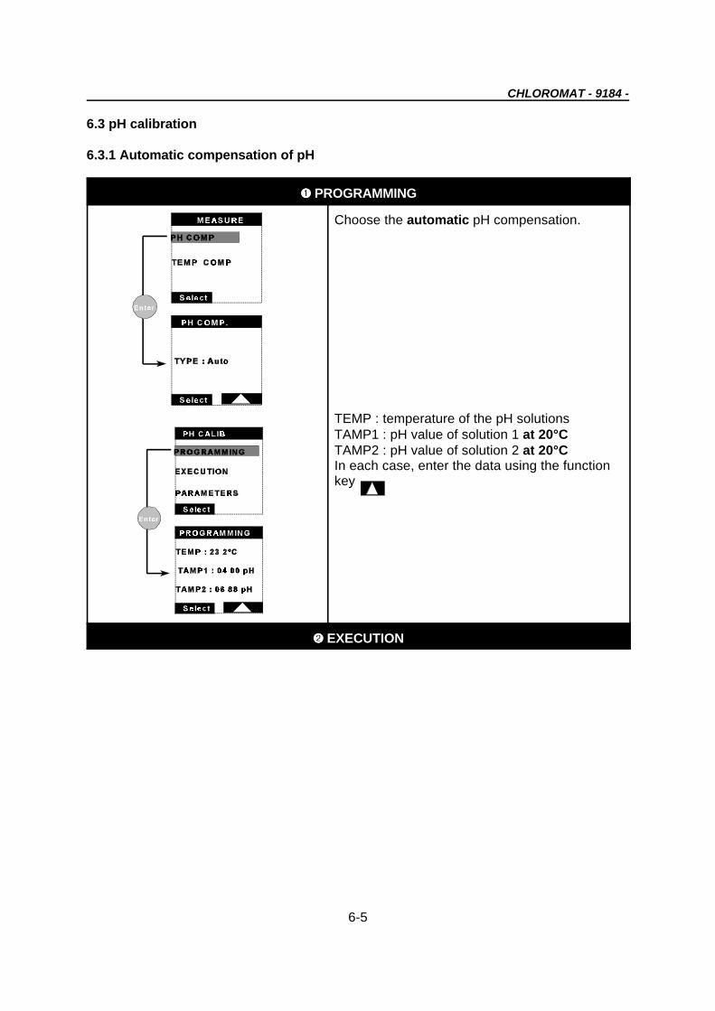
6.3 pH calibration
6.3.1 Automatic compensation of pH
ìì PROGRAMMING
Choose the automatic pH compensation.
TEMP : temperature of the pH solutionsTAMP1 : pH value of solution 1 at 20°CTAMP2 : pH value of solution 2 at 20°CIn each case, enter the data using the functionkey
íí EXECUTION

25.0°C
SOLUTION 1
PRESS ENTER
4.00PH
6.88PH
25.0 °C
SOLUTION 2
PRESS ENTER
CHLOROMAT - 9184 -
6-6
Select the CALIB menu.Place the pH probe in a beaker containing thesolution 1. Press ENTER to start the calibration.The screen displays then the measured pH valueof solution 1, and the temperature entered in thePROGRAMMING menu. Wait for the stabilisationof the measurement, then press OK to validatethe first point.Operate the same way for solution 2 (secondpoint).
After the validation of the second point, thescreen displays the calibration parameters :DATE : enter the date of the calibrationZERO : gap at the origin of the electrodeSLOPE : expressed in % of the theoritical slope(-59.16 mV/pH @ 25°C)
ATTENTION !You may return to the previous screen bypressing ENTER or ESC.Using the ESC key cancels calibration, theprevious parameters are stored.
Remark : you may quit the CALIBRATION modeat any time by pressing ESC.
ÐÐ PARAMETERS
In the CALIBRATION menu, select pH CALIBthen PROGRAMMING. Select PARAMETERSthen press ENTER. The screen displays then therunning parameters of the pH probe :DATE : Calibration date entered during theprevious calibrationZERO : pH electrode offsetSLOPE : pH electrode slope expressed in % ofthe theoritical slope (-59.16 mV/pH @ 25°C)

CHLOROMAT - 9184 -
6-7
6.3.2 pH manual compensation
ÎÎ PROGRAMMING
Choosing the compensation type. 2 optionsare possible, select Manual.Enter the pH value, digit by digit, with the
key
Press ESC to quit the menu.
ÏÏ EXECUTION
No execution in the manual mode.


CHLOROMAT - 9184 -
7-1
Chapter 7 : Start up, maintenance andtroubleshooting
7.1 Start up
7.1.1 Assembling the probe
The probe is composed of the following items :
1 : Nut2 : measuring electrode3 : Electrolyte filling screw4 : Probe body5 : Membrane

CHLOROMAT - 9184 -
7-2
Proceed as follows for the assembling :
Screw the membrane on the body till the dead stop.Fill in the probe body with 5 ml of electrolyte.Insert the electrode, screw the fastening nut.Mount the electrolyte filling screw.
Recommandations :
=> the membrane needs to be perfectly screwed.=> make sure the electrolyte contains no impurity.=> push the electrode slowly inside the body.

CHLOROMAT - 9184 -
7-3
7.1.2 Mounting the probe within the cell
A) mount the fittingsB) then fix the cell (screw : i4 maxi, inlet and outlet tubing : 35 mm mini)C) Insert the inlet and outlet nozzles. Recommanded dimensions are :
inlet tubing : iinter/exter : 4/6outlet tubing : iinter/exter : 6/8
Avoid any restriction on the drain.D) install the sensor, and fasten it with the ring.E) you can now use your instrument with a water flow of about 12-15 l/h.
7.1.3 Probe connection
See figure 3-2 page 3-3 for the electrical connection. The standard length of the cable is 10m.
7.1.4 Main power supply connection
Proceed to the connections as shown on drawing 3-7 on page 3-2.

Yes No
CHLOROMAT - 9184 -
7-4
7.1.5 Starting up the analyser
When switched on, the analyser operates an automatic test of its electronics and displays afirst value. Wait till stabilization of the measurement. You should not calibrate the analyserbefore the temperature and the concentration are stable. (See chapter 6).
Note 1 : There is electrolyte in the probe, keep it head down when you remove it from thewater.

CHLOROMAT - 9184 -
7-5
7.2 Changing the membrane
Operate as follows :
=> stop the water admission, withdraw the connector from the probe. Make sure thealarms are not raised by this operation. You may choose the maintenance mode toavoid this situation.
A) Unscrew the cell fastening ring, extract the sensorB) Unscrew the electrode nut and the electrolyte filling screwC) Extract the electrode, empty the electrolyteD) Unscrew the worn membrane, replace it by a new one
To mount it again, operate following the other way round (refer to assembling theelectrode)
Recommandations :
=> never pull firmly the electrode when the electrolyte filling screw is in place=> do not touch the active part of the membrane=> when installing the electrode, pre-position it with care, it will find its place justwith gravity=> screw the membrane until it reaches the mechanical thrust :
CHLOROMAT - 9184 -
7-6
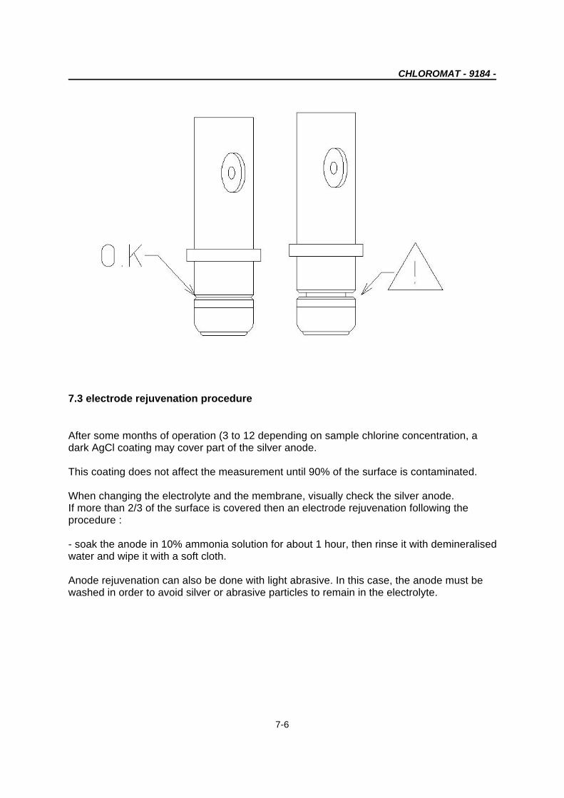
7.3 electrode rejuvenation procedure
After some months of operation (3 to 12 depending on sample chlorine concentration, adark AgCl coating may cover part of the silver anode.
This coating does not affect the measurement until 90% of the surface is contaminated.
When changing the electrolyte and the membrane, visually check the silver anode.If more than 2/3 of the surface is covered then an electrode rejuvenation following the procedure :
- soak the anode in 10% ammonia solution for about 1 hour, then rinse it with demineralisedwater and wipe it with a soft cloth.
Anode rejuvenation can also be done with light abrasive. In this case, the anode must bewashed in order to avoid silver or abrasive particles to remain in the electrolyte.

CHLOROMAT - 9184 -
7-7
Problem : Important instability of the readings
Problem : Lack of accuracy
7.4 Functional troubleshooting
Causes and solutions :
a) There is humidity or water in the probe connector"" Dry the connector and check it is correctly screwed.
b) Uncorrect connection"" Check the connections of the transmitter to the probe
c) Important electromagnetic interferences close to the probe or transmitter cable"" Find a better place for the cable and check the EMC level.
d) Temporary interference with other elements, generally ClO , O2 3
e) Flowrate too low (10 ml/h minimum, 12-15 l/h recommanded)"" Increase the sample flow
Causes and solutions :
a) The membrane permeability has changed (dirt deposit)"" Calibrate the analyser and check if the concentration is back to normal
b) Pollution of the electrolyte"" Check the parts to screw (membrane, filling screw) and replace the electrolyte.
c) leak of electrolyte"" Check the parts to screw (membrane, filling screw) and change the electrolyte.
d) Error during calibration or uncorrect calibration"" calibrate again to check the parameters. If the error is confirmed, check the

CHLOROMAT - 9184 -
7-8
Other problems
calibration current (too high, too low or unstable)
e) The temperature sensor calibration has not been operated"" Check the temperature given by the transmitter and calibrate it (see page 6-2). Ifyou have chosen the manual compensation check the value is correct.
f) Flowrate too low (10 l/h minimum, 12-15 l/h recommended)"" Check the sample inlet circuit
g) The sample temperature or pressure is out of the specifications"" Change the probe location or modify the sample so that it meets the specifications.
h) The electrolyse potential is not equal to -50 mv"" Enter the correct value.
i) Presence of an interferent, generally ClO , O2 3
a) The probe current is nul when measuring"" There is no electrolyte in the probe (leak)/the electrolyte is not under air pressure
b) The probe current is negative"" Connection problem to the anode circuit (loose contact)"" Leak of electrolyte at the membrane : replace it
c) The sample temperature does not correspond to the specifications"" There may be a short-circuit on the temperature connection or temperature sensorcalibration was not performed properly.

CHLOROMAT - 9184 -
7-9
7.4 Electric troubleshooting
WARNING !Never attempt servicing before disconnecting the instrument
MALFUNCTION POSSIBLE CAUSE REMEDIES
No indication No power ; instrument is not Check for power, then check if connectedconnected correctly properly
Defective fuse Check fuse
Instrument's power supply set for Check jumpers on power-supply board forwrong line voltage correct voltage settings
Ribbon cable connecting power with Check that the ribbon plugs are properlyCPU board not properly plugged in plugged in.
Connection between CPU board and Check plug connectionsmeasurement module loose
Short circuit in power-supply board Visually check power-supply board forshorts
Hardware is defective Call the Service Technician
LCD displays undefined Malfunctionning CPU board or Using the Instruction manual, program thecharacters processor instrument to load the default values
CPU hardware RESET the instrument by temporarilyinterrupting the power (5-10 secs.)
Call the Service Technician
Keyboard does not operate ; all CPU malfunctioinning, external If there is no response, RESET thekeys are inactive interferences instrument by temporarily interrupting the
power (5-10 seconds.). Check each keyagain. If there is no change, call theService Technician.
Measurement is not correct Instrument was programmed recheck programmed parameters. Do theyincorrectly agree with the probe's characteristics ?
System, including probe, not Calibrate the whole system (probecalibrated correctly. connected).
Probe connected wrong. Recheck all probe connections
Probe malfunctionning, possibly Visually check the condition of the probe. Isincompatible with the application. the application within the probe's
specifications (data sheet) ?
CPU board is defective. If error persists, call the ServiceTechnician.
Measurement is not stable Faulty probe Check the condition of the probe. Is itcontaminated ?
Probe connected wrong Is the probe connected correctly ?
Interferences Are there any sources of potentialinterference, chemical, external,temperature, pressure, etc...?

CHLOROMAT - 9184 -
7-10
Cable shield is not connected Check and connect
Defective CPU board If problem persists, call the ServiceTechnician.
Temperature measurement is not Probe connected wrong Is the probe properly connected ? Check.correct
Temperature was not calibrated Calibrate for temperature. Also check thePt100 for correct resistance (ohmmeter).
CPU board is defective If problem persists, call the ServiceTechnician.
Display reading static ; cannot be Malfunctionning CPU board and/or Check to make sure that probe ischanged in any way some other transmitter hardware is connected correctly.
defective.
Initiate a software RESET.
If steps 1-3 do not remedy the problem,make a cold start (RESET) : interrupt thepower for 5-10 secs.
Reprogram the instrument again.
If problem persists, call the ServiceTechnician.
Relays not energised Instrument was programmed Check whether the correct relayincorrectly parameters and setpoints have been
programmed.
Hardware is defective Check that the programmed setpoints arecompatible with the programmedmeasuring range.
Check the relay characteristics for properfunctionning using an ohmmeter.
If problem persists, contact the ServiceTechnician.
Wrong output current, output Instrument was incorrectly Check the proggrammed output-currentcurrent remains locked at 0 or 20 programmed parametersmA
Connection of the Monec with Check the cablesperipherals (recorder, etc.) are faulty,loose or defective.
Hardware is defective Compare the measured value with theoutput-current range
If problem persists, call the ServiceTechnician
Polarization voltage uncorrect Wrong configuration (3 electrode Check the swiches under the amperometricmode) board are correctly positionned ( “on”).
Wrong programming

CHLOROMAT - 9184 -
8-1
OUT OF 4/20mA
@ 10 : 00
Chapter 8 : Warning messages
This message appears when the measured value is out of the range programmedfor analog outputs 1 or 2 (PROGRAMMING / mA OUTPUTS/ X OUTPUT).
When you use the S4 relay as a Timer, a countdown clock indicates the remainingtime before the next relay gets activated. Time is expressed in hours : minutesexcept for the last 10 minutes, when it is expressed in hours : minutes :secondes.


CHLOROMAT - 9184 -
9-1
Chapter 9 : Error messages
L In case of errors, measurements are replaced by dashes “- - -”.
Error messages Description
Error messages during a measurement
The concentration value is out of the limits. Checkthe current value and the calibration parameters.
The concentration value is out of the limits. Checkthe current value and the calibration parameters.
The sample temperature is out of the limits. Check ifthere is any short-circuit or open circuit, or waterinside probe connector.
The current value is out of the limits. Check theelectrode and its connections.

CHLOROMAT - 9184 -
9-2
The current value is out of the limits. Check there isno short-circuit on the measuring line. Check thepolarization voltage.
The pH value is inferior to -3 pH.
The pH value is superior to 14.0 pH.
Error messages during a calibration
The temperature difference between the calibrationand the sensor theoretical response is superior tothe programmed limit.Limits : ± 20°C

CHLOROMAT - 9184 -
A1-1
Appendix 1 : Temperature conversion table
3 Conversion from C into F : F = 1,8 x C + 32B B B B
3 Conversion from C into K : K = C + 273,15B B B B
C F K C F KBB BB BB
0 32 273,15 24 75.2 297.15
1 33,8 274,15 25 77 298.15
2 35,6 275,15 26 78.8 299.15
3 37,4 276,15 27 80.6 300.15
4 39,2 277,15 28 82.4 301.15
5 41 278.15 29 84.2 302.15
6 42.8 279.15 30 86 303.15
7 44.6 280.15 31 87.8 304.15
8 46.4 281.15 32 89.6 305.15
9 48.2 282.15 33 91.4 306.15
10 50 283.15 34 93.2 307.15
11 51.8 284.15 35 95 308.15
12 53.6 285.15 36 96.8 309.15
13 55.4 286.15 37 98.6 310.15
14 57.2 287.15 38 100.4 311.15
15 59 288.15 39 102.2 312.15
16 60.8 289.15 40 104 313.15
17 62.6 290.15 41 105.8 314.15
18 64.4 291.15 42 107.6 315.15
19 66.2 292.15 43 109.4 316.15
20 68 293.15 44 111.2 317.15
21 69.8 294.15 45 113 318.15
22 71.6 295.15
23 73.4 296.15
BB BB BB


CHLOROMAT - 9184 -
A2-1
Appendix 2 : Default values
CALIBRATION
CONC. CALIB. PARAMETERSOFFSET DATE :01/01/98Type : AutoElec. S : 0 nA/ppmSLOPE )T : 0.0 °C
PROGRAMMING
MEASURE
COMP. TEMP.SENSOR : NTCTYPE : AutoCOMP PHTYPE : AUTO
ALARMS
ALARMS S1/S2/S4 ALARM S3AFFECT. : Conc. AFFECT. : SystemLIM. : 0.00 ppb ACQUIT : AutoDIR. : Low RELAY : NFDELAY : 000 sHYST. : 00%RELAY : NO
mA OUTPUTS
OUTPUT 1 OUTPUT 2AFFECT. : TFC. AFFECT. : TFC.TYPE : 4-20 TYPE : 4-20MODE : Lin. MODE : Lin.LOW : 0.000 ppm LOW : 0.000 ppmUP : 1.000 ppm UP : 1.000 ppm
SPECIAL PROG.

CHLOROMAT - 9184 -
A2-2
MAINTENANCE CALIBRATIONMODE : memo MODE : memo
TIMER ALARM SYSTEMMODE : memo MODE : memo
RS485
No : 0BAUD : 9600PARITY : NoSTOP BIT : 1
SERVICE
AVERAGE
AVERAGE : 1
DISPLAY
DISPLAYCONC. : ppb/ppmTEMP. : °CLANGUAGE : GB
CODE
CODECALIB. : 0000PROG. : 0000SERVICE : 0000
CONFIGURATION
CONFIGURATIONFREQ. : 50 Hz

CHLOROMAT - 9184 -
A3-1
APPENDIX 3 : Details of the cable connections
Rep Colour Function Rep. Connector
1 Black T + 1
2 Blue T - 2
3 White Work 3
4 Red Counter 4
5 White GND
6 White Ground


CHLOROMAT - 9184 -
A4-1
Appendix 4 : Security data sheet
Pure anhydrous dipotassium hydrogenphosphate
COMPOSITION/COMPONENTS INFORMATION
Cas : 7758-11-4Molecular weight : 174.18Molecular formula : K2HPO4EINECS : 231-834-5
DANGER IDENTIFICATION
The product is not submitted to legislation (EC Directive 67/548/CEE)
FIRST AID MEASURES
In case of contact with the skin, immediately flush with copious amounts of water while removingcontaminated clothing and shoes. Assure adequate flushing (for at least 10 minutes) of the eyes byseparating the eyelids with fingers. Consult a specialist. If inhaled, remove to fresh air. If swallowed,wash out mouth with water provided person is conscious, try to make the person vomit. Call aphysician immediately.
FIRE FIGHTING MEASURES
Appropriate extinguishing media : adapt the extinguishing agent to the environment.Specific danger : not combustible
ACCIDENTAL RELEASE MEASURES
Collect when dry. Evacuate the product to eliminate it. Wash spill site.
HANDLING AND STORAGE
Handling : no other specificationStorage :Stock the container hermetically closed in a dry, air-sealed area, at room temperature (+15to +25°C).
EXPOSURE CONTROLS/PERSONAL PROTECTION
Respiratory system protection : necessary in case of dust formation.Hands protection : necessaryEyes protection : necessaryIndustrial hygienic measure : take off any contaminated. Wash your hands after handling.

CHLOROMAT - 9184 -
A4-2
PHYSICAL AND CHEMICAL PROPERTIES
Color : whitePh : about 9.1 - 100 g/l of water (20°C)Melting temperature : not applicableEbullition temperature :not applicableSelf-ignition temperature : not applicableIgnition point : not applicableExplosion limit in the air : not applicableDensity : (20°C) 2.44 g/cm3
Bulk density : about 700-1000 kg/m3
Thermal dissociation : > 180°CSolubility : hardly soluble - 1600 g/l (20°C)
STABILITY AND REACTIVITY
Conditions to avoid : noneMaterials to avoid : noneDangerous decomposition products : none
TOXICOLOGICAL INFORMATION
Substance property : low toxicityHydrous solution : if the chemical product acted long
ECOLOGICAL INFORMATION
If the substance is handled and used in a proper way, there should not be any ecological problem.Components of phosphorous and/or nitrogen may, depending on their concentration, contribute tonatural water eutrophication.
DISPOSAL CONSIDERATIONS
Contact a licensed professional waste disposal service to dispose of this material.
The above information is believed to be correct but does not purport to be all inclusive and shall beused only as a guide.
Very pure potassium di-hydrogenphosphate cristals
COMPOSITION/COMPONENTS INFORMATION
Cas : 7778-70-0Molecular weight : 136.09Molecular formula : H2KO4PEINECS : 231-913-4
DANGER IDENTIFICATION

CHLOROMAT - 9184 -
A4-3
The product is not submitted to legislation (EC Directive 67/548/CEE)
FIRST AID MEASURES1
In case of contact with the skin, immediately flush with copious amounts of water while removingcontaminated clothing and shoes. Assure adequate flushing (for at least 10 minutes) of the eyes byseparating the eyelids with fingers. Consult a specialist. If inhaled, remove to fresh air. If swallowed,wash out mouth with water provided person is conscious, try to make the person vomit. Call aphysician immediately.
FIRE FIGHTING MEASURES
Appropriate extinguishing media : adapt the extinguishing agent to the environment.Specific danger : not combustible
ACCIDENTAL RELEASE MEASURES
Collect when dry. Evacuate the product to eliminate it. Wash spill site.
HANDLING AND STORAGE
Handling : no other specificationStorage :Stock the container hermetically closed in a dry, air-sealed area, at room temperature (+15to +25°C).
EXPOSURE CONTROLS/PERSONAL PROTECTION
Respiratory system protection : necessary in case of dust formation.Hands protection : necessaryEyes protection : necessaryIndustrial hygienic measure : take off any contaminated. Wash your hands after handling.
PHYSICAL AND CHEMICAL PROPERTIES
Color : whitePh : about 4.4 - 50 g/l of water (20°C)Melting temperature : 253°CEbullition temperature :not applicableSelf-ignition temperature : not applicableIgnition point : not applicableExplosion limit in the air : not applicableDensity : (20°C) 2.34 g/cm3
Bulk density : about 1200 kg/m3
Thermal dissociation : > 253°CSolubility : hardly soluble - 222 g/l (20°C)
STABILITY AND REACTIVITY
Conditions to avoid : noneMaterials to avoid : noneDangerous decomposition products : none
TOXICOLOGICAL INFORMATION

CHLOROMAT - 9184 -
A4-4
Substance property : low toxicityHydrous solution : if the chemical product acted longIrritations in case of contact with the skin
ECOLOGICAL INFORMATION
If the substance is handled and used in a proper way, there should not be any ecological problem.Components of phosphorous and/or nitrogen may, depending on their concentration, contribute tonatural water eutrophication.
DISPOSAL CONSIDERATIONS
Contact a licensed professional waste disposal service to dispose of this material.
The above information is believed to be correct but does not purport to be all inclusive and shall beused only as a guide.
CHLOROMAT - 9184 -
A5-1
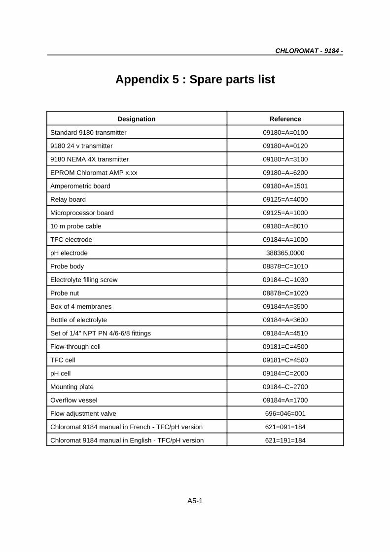
Appendix 5 : Spare parts list
Designation Reference
Standard 9180 transmitter 09180=A=0100
9180 24 v transmitter 09180=A=0120
9180 NEMA 4X transmitter 09180=A=3100
EPROM Chloromat AMP x.xx 09180=A=6200
Amperometric board 09180=A=1501
Relay board 09125=A=4000
Microprocessor board 09125=A=1000
10 m probe cable 09180=A=8010
TFC electrode 09184=A=1000
pH electrode 388365,0000
Probe body 08878=C=1010
Electrolyte filling screw 09184=C=1030
Probe nut 08878=C=1020
Box of 4 membranes 09184=A=3500
Bottle of electrolyte 09184=A=3600
Set of 1/4" NPT PN 4/6-6/8 fittings 09184=A=4510
Flow-through cell 09181=C=4500
TFC cell 09181=C=4500
pH cell 09184=C=2000
Mounting plate 09184=C=2700
Overflow vessel 09184=A=1700
Flow adjustment valve 696=046=001
Chloromat 9184 manual in French - TFC/pH version 621=091=184
Chloromat 9184 manual in English - TFC/pH version 621=191=184


CHLOROMAT - 9184 -
A6-1
Appendix 6 : RS485 MODBUS-JBUS addressing
CALIBRATION menu
/CONC. CALIB. /ZERO
/PROGRAMMING /Type (0:ElecAuto, 1:Chemical) 0121/EXECUTION
/SLOPE /EXECUTION /TEMP. CALIB.. /EXECUTION /PH CALIB
/PROGRAMMING/TEMP 421/TAMP1 422/TAMP2 423
/EXECUTION/PARAMETERS
MEASURE menu
/ TEMP. COMP.Sensor (0 : NTC, 1 : AD590) 1210 /Type (0:Manual,1:Auto) 1220 /Temp. 1230
ALARMS menu
/ALARM1 /Affect (0:conc, 1:°C/°F, 2:No) 2120 /Lim. 2130 /Dir. (0:Low, 1:Up) 2140 /Delay 2150 /Hyst. 2160 /Relay (0:N.O., 1:N.C.) 2170
/ALARM2 /Affect (0:conc, 1:°C/°F, 2:No) 2220 /Lim. 2230 /Dir. (0:Low, 1:Up) 2240 /Delay 2250 /Hyst. 2260 /Relay (0:N.O., 1:N.C.) 2270
/ALARM3 /Mode (0:Limit, 1:Syst, 2:No) 2310 /Affect (0:conc, 1:°C/°F, 2:No) 2320 /Lim. 2330 /Dir. (0:Bas, 1:Haut) 2340 /Delay 2350 /Hyst. 2360 /Relay (0:N.O., 1:N.C.) 2370 /Accept 2380

CHLOROMAT - 9184 -
A6-2
/ALARM4 (0:Manu, 1:Auto) 2410 /Mode 2420 /Affect (0:Limit, 1:Timer, 2:No) 2430 /Lim. (0:conc, 1:°C/°F, 2:No) 2440 /Dir. 2450 /Delay (0:Low, 1:Up) 2460 /Hyst. 2470 /Relay 2401 /Interv (0;N.O., 1:N.C.) 2402 /Impul. 2403 /Ton 2404 /Toff 2405 /TmA
mA OUTPUTS menu
/OUTPUT1 /Affect (0:HOCl, 1:°C/°F, 2 : TFC; 3 : pH) 4110 /Type (0:0/20mA, 1:4/20mA) 4120 / Mode (0:lin, 1:dual) 4150 /Low 4130 / Mid. 4160 /Upp. 4140/OUTPUT2 /Affect (0:HOCl, 1:°C/°F, 2 : TFC; 3 : pH) 4210 /Type (0:0/20mA, 1:4/20mA) 4220 /Mode (0:lin, 1:dual) 4250 /Low 4230 /Mid. 4260 /Upp. 4240 /SPECIALPROG. /MAINTENANCE /Mode (0:Live, 1:Last, Preset) 4311 /Value 4312 /CALIBRATION /Mode (0:Live, 1:Last, 2:Preset) 4321 /Value 4322 /SYST. ALARM /Mode (0:Live, 1:Last, 2:Preset) 4331 /Value 4332 /TIMER /Mode (0:Live, 1:last, 2:Preset) 4341 /Value 4342 /TEST
RS485 menu
/N° 5100/Baud (0:300, 1:600, 2:1200, 3:2400, 5200/Parity 4:4800, 5:9600) 5300/Stop bit (0:No, 1:Odd, 2:Even) 5400
(0:1bit, 2:2bits)
SERVICE menu
CHLOROMAT - 9184 -
A6-3
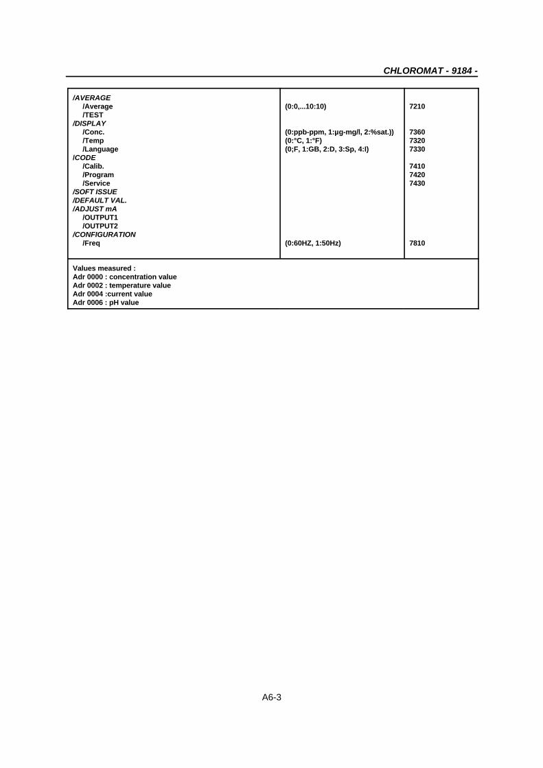
/AVERAGE /Average (0:0,...10:10) 7210 /TEST/DISPLAY /Conc. (0:ppb-ppm, 1:µg-mg/l, 2:%sat.)) 7360 /Temp (0:°C, 1:°F) 7320 /Language (0;F, 1:GB, 2:D, 3:Sp, 4:I) 7330/CODE /Calib. 7410 /Program 7420 /Service 7430/SOFT ISSUE/DEFAULT VAL./ADJUST mA /OUTPUT1 /OUTPUT2/CONFIGURATION /Freq (0:60HZ, 1:50Hz) 7810
Values measured :Adr 0000 : concentration valueAdr 0002 : temperature valueAdr 0004 :current valueAdr 0006 : pH value


