21
Installation and Operating Instructions Circular duct fan Systemair prioAir GB
Installation and Operating Instructions
Circular duct fanSystemair prioAir
GB
Contents
1 General information ..............................................26
1.1 List of information ..................................................... 26
1.2 Notes on the documentation................................... 27
2 Important safety information ..............................27
2.1 Safety notes ............................................................... 27
2.2 Personnel .................................................................... 27
2.3 Intended use ............................................................... 28
2.4 Incorrect use ............................................................... 28
3 Warranty ................................................................28
4 Delivery, transport, storage .................................29
4.1 Delivery ....................................................................... 29
4.2 Transport ..................................................................... 29
4.3 Storage ........................................................................ 29
5 Description .............................................................30
5.1 Circular duct fan prio 200 EC and prio 200 E2 ...... 30
5.2 Type key ...................................................................... 32
5.3 Technical data ............................................................ 33
5.4 Safety devices ............................................................ 33
5.5 Instructions regarding motor and controller......... 33
6 Installation .............................................................34
6.1 Safety information .................................................... 34
6.2 Preconditions for installation .................................. 34
6.3 Assembly of the fan .................................................. 34
7 Electrical connection .............................................35
7.1 Wiring diagram prio 200 E2 ..................................... 35
7.2 Wiring diagram prio 200 EC ..................................... 36
8 Commissioning ......................................................37
8.1 Preconditions .............................................................. 37
8.2 Commissioning ........................................................... 37
9 Operation ...............................................................38
9.1 Safety notes ............................................................... 38
9.2 Operating conditions ................................................. 38
9.3 Operation/use ............................................................ 38
10 Maintenance/troubleshooting .............................39
10.1 Faults and troubleshooting ...................................... 39
10.2 Cleaning ....................................................................... 40
10.3 Maintenance, service ................................................ 40
10.4 Spare parts .................................................................. 40
11 Uninstalling/dismounting .....................................41
12 Disposal ..................................................................41
12.1 Disposal of the circular duct fan ............................. 41
12.2 Disposal of packaging ............................................... 41
13 EC-Declaration of Conformity ...............................42
Notes ................................................................................43
25
1 General information
1.1 List of information
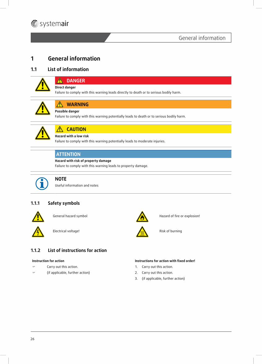
DANGERDirect dangerFailure to comply with this warning leads directly to death or to serious bodily harm.
WARNINGPossible dangerFailure to comply with this warning potentially leads to death or to serious bodily harm.
CAUTIONHazard with a low riskFailure to comply with this warning potentially leads to moderate injuries.
ATTENTIONHazard with risk of property damageFailure to comply with this warning leads to property damage.
NOTEUseful information and notes
1.1.1 Safety symbols
General hazard symbol Hazard of fi re or explosion!
Electrical voltage! Risk of burning
1.1.2 List of instructions for action
Instruction for action Instructions for action with fi xed order!
Carry out this action. 1. Carry out this action.
(if applicable, further action) 2. Carry out this action.
3. (if applicable, further action)
26
General information
1.2 Notes on the documentation
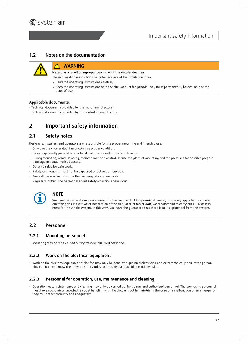
WARNINGHazard as a result of improper dealing with the circular duct fanThese operating instructions describe safe use of the circular duct fan. » Read the operating instructions carefully! » Keep the operating instructions with the circular duct fan prioAir. They must permanently be available at the
place of use.
Applicable documents:- Technical documents provided by the motor manufacturer- Technical documents provided by the controller manufacturer
2 Important safety information
2.1 Safety notesDesigners, installers and operators are responsible for the proper mounting and intended use.• Only use the circular duct fan prioAir in a proper condition.• Provide generally prescribed electrical and mechanical protective devices.• During mounting, commissioning, maintenance and control, secure the place of mounting and the premises for possible prepara-
tions against unauthorised access.• Observe rules for safe work.• Safety components must not be bypassed or put out of function.• Keep all the warning signs on the fan complete and readable.• Regularly instruct the personnel about safety-conscious behaviour.
NOTEWe have carried out a risk assessment for the circular duct fan prioAir. However, it can only apply to the circular duct fan prioAir itself. After installation of the circular duct fan prioAir, we recommend to carry out a risk assess-ment for the whole system. In this way, you have the guarantee that there is no risk potential from the system.
2.2 Personnel
2.2.1 Mounting personnel• Mounting may only be carried out by trained, qualifi ed personnel.
2.2.2 Work on the electrical equipment• Work on the electrical equipment of the fan may only be done by a qualifi ed electrician or electrotechnically edu-cated person.
This person must know the relevant safety rules to recognise and avoid potentially risks.
2.2.3 Personnel for operation, use, maintenance and cleaning• Operation, use, maintenance and cleaning may only be carried out by trained and authorized personnel. The oper-ating personnel
must have appropriate knowledge about handling with the circular duct fan prioAir. In the case of a malfunction or an emergency they must react correctly and adequately.
27
Important safety information
2.3 Intended useThe circular duct fans prioAir are intended for installation in ventilation systems. They can be installed either in duct systems or as a free sucking fan over a nozzle and a sucking side protection grid. A free blow-out and/or suction device via a contact-protection grid is possible following consideration in the design.• The circular duct fans prioAir are suitable for extraction of clean air, air with a low dust and grease content, media up to max. den-
sity of 1,3 kg/m³ and a maximum permissible humidity of 95 %.• The maximum permissible operating data on the name plate apply for an air density ρ = 1,2 kg/m³ (sea level) and a maximum air
moisture of 80 %. • The circular duct fans prioAir are suitable for the following ambience and conveyed medium temperature range:
– prio 200 EC from -25 °C to +55 °C – prio 200 E2 from -30 °C to +55 °C
2.4 Incorrect useAbove all, the incorrect use means using the circular duct fans prioAir in a way other than that described. The following points are incorrect and hazardous:• Operation in medical devices with life-sustaining or life-supporting function• Extraction of explosive and combustible media,• Extraction of aggressive, dust or grease containing media,• Outdoor installation without weather protection,• Operation in an explosion hazardous atmosphere,• Operation without duct system or protective guard,• Operation with the air connections closed
3 WarrantyWarranty for our products shall be based on the contractual stipulations, our quotations and also as a supplement our General Terms and Conditions of Business. Warranty claims shall presuppose that the products are connected prop-erly, operated and used in accordance with the data sheets and are also maintained as required.
28
Warranty
4 Delivery, transport, storage
4.1 DeliveryEach device leaves our plant in an electrically and mechanically proper condition. The circular duct fans prioAir are on pallets. We recommend to transport them to the installation site in original packaging.
CAUTIONDanger from cutting edges! » Wear protective gloves when unpacking.
Check delivery Check the circular duct fan prioAir for obvious defects, which can impair safe operation. First of all, pay attention for defects on the connection cable, terminal box and rotor, cracks in the housing, missing rivets,
screws or covering caps.
4.2 Transport
WARNINGHazard of impact if the circular duct fan falls down! » Transport the fan carefully!
WARNINGElectrical hazard from damaged connections » Do not use the terminal box or rotor for transport.
Transport the prioAir circular duct fan in its original packing material. Avoid shocks or impact.
5 Storage
CAUTIONHazard due to loss of function of the motor bearings! » Avoid storing for too long time (recommendation: max. 1 year). » Before installation, check proper function of the motor bearings
Store the circular duct fan prioAir in the original packaging dustproof, dry and protected against weather. Avoid effects of extreme heat or cold.
29
Delivery, transport, storage
5 Description
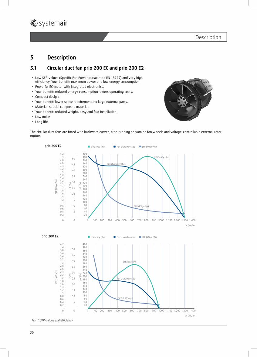
5.1 Circular duct fan prio 200 EC and prio 200 E2
• Low SFP-values (Specifi c Fan Power pursuant to EN 13779) and very high effi ciency. Your benefi t: maximum power and low energy consumption.
• Powerful EC-motor with integrated electronics.• Your benefi t: reduced energy consumption lowers operating costs.• Compact design.• Your benefi t: lower space requirement, no large external parts.• Material: special composite material.• Your benefi t: reduced weight, easy and fast installation.• Low noise• Long life
The circular duct fans are fi tted with backward curved, free-running polyamide fan wheels and voltage-controllable external rotor motors.
prio 200 EC
prio 200 E2
Fig. 1: SFP-values and effi ciency
qv (m3/h)
20406080
100120140160180200220240260280300320340360380400
Efficiency (%) Fan characteristics SFP (kW/m3/s)
psf (
Pa)
00
5
10
15
20
25
30
35
40
45
50
0,20,40,60,8
11,21,41,61,8
22,22,42,62,8
33,23,43,63,8
4,24
SFP
(kW
/m3 /
s)
E (%
)
SFP (kW/m3/s)
Fan characteristics
Efficiency (%)
0 800 900 1000 1.100 1.200 1.300 1.400700600500400300200100
SFP (kW/
qv (m3/h)
20406080
100120140160180200220240260280300320340360380400
Efficiency (%) Fan characteristics SFP (kW/m3/s)
psf (
Pa)
00
5
10
15
20
25
30
35
40
45
50
0,20,40,60,8
11,21,41,61,8
22,22,42,62,8
33,23,43,63,8
4,24
SFP
(kW
/m3 /
s)
E (%
)
SFP (kW/m3/s)
Fan characteristics
Efficiency (%)
0 800 900 1000 1.100 1.200 1.300 1.400700600500400300200100
30
Description
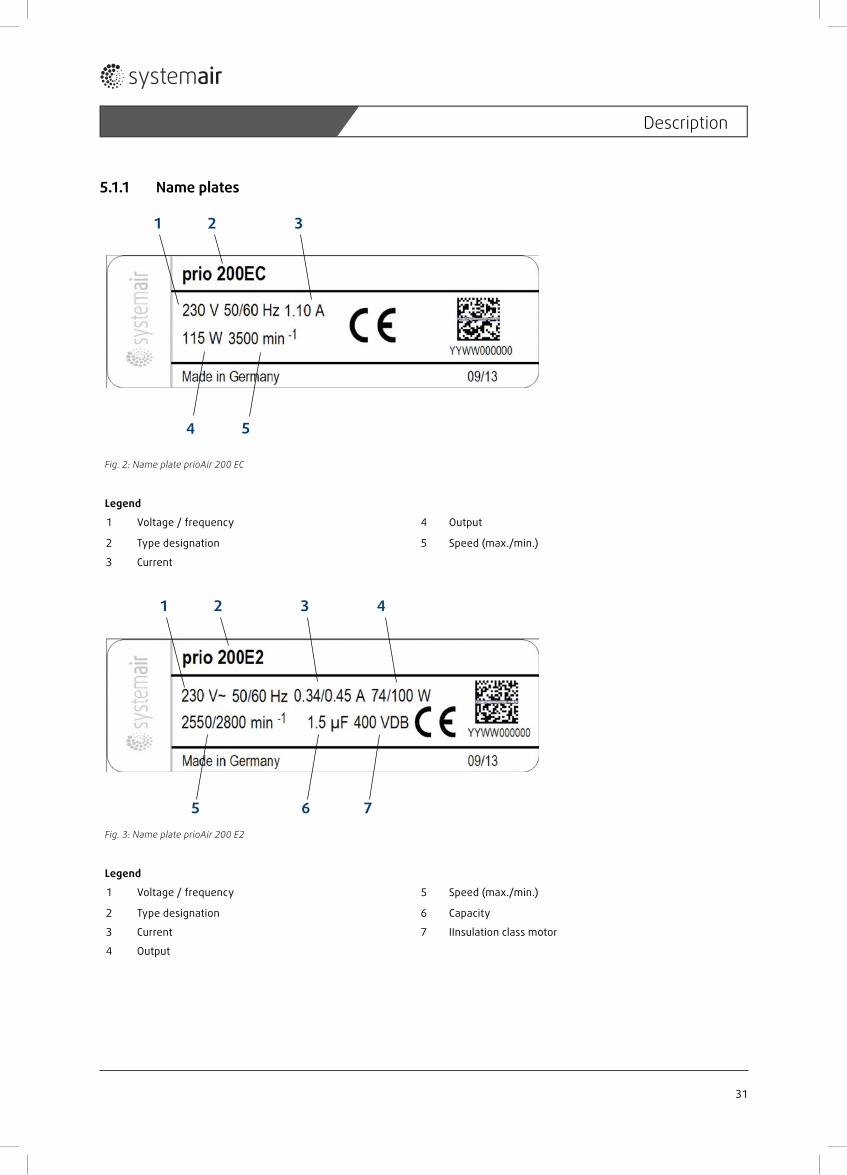
5.1.1 Name plates
54
31 2
Fig. 2: Name plate prioAir 200 EC
Legend
1 Voltage / frequency 4 Output
2 Type designation 5 Speed (max./min.)
3 Current
6 7
3 41
5
2
Fig. 3: Name plate prioAir 200 E2
Legend
1 Voltage / frequency 5 Speed (max./min.)
2 Type designation 6 Capacity
3 Current 7 IInsulation class motor
4 Output
31
Description
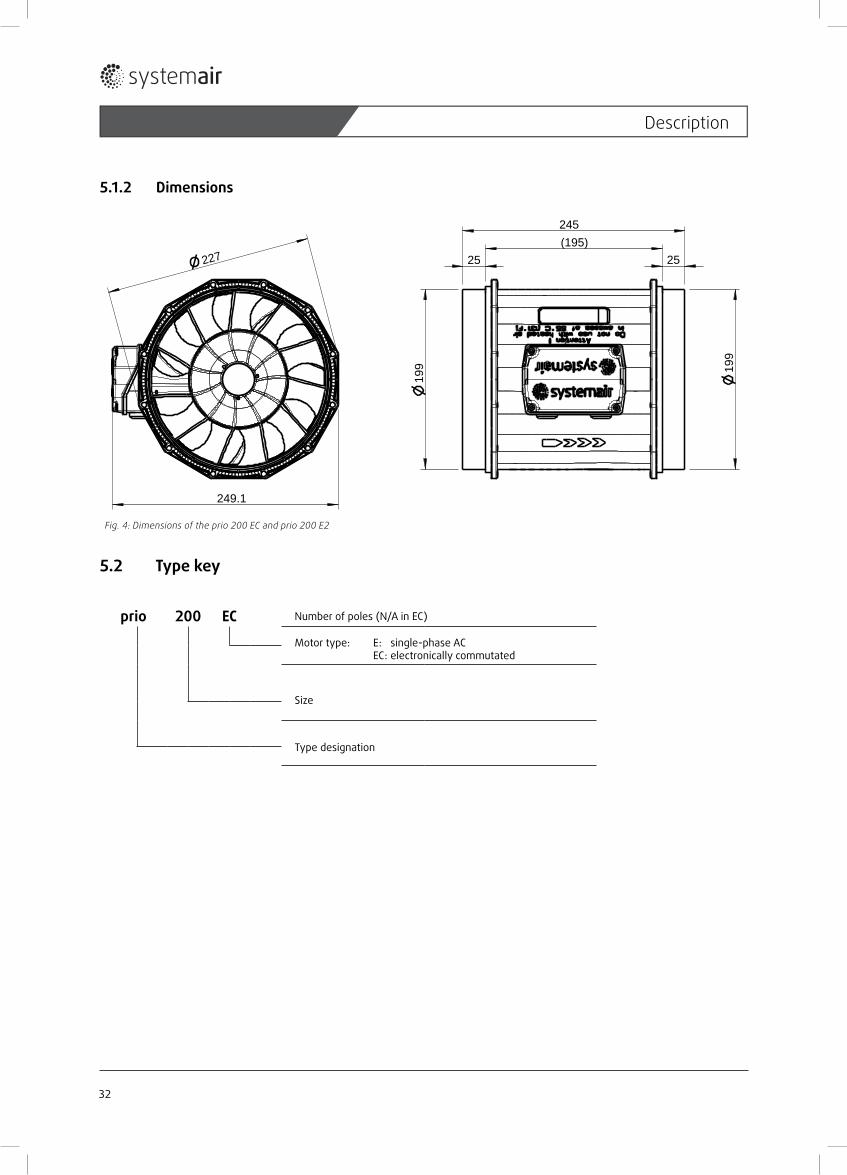
5.1.2 Dimensions
245(195)
227
249.1
199
199
2525
Fig. 4: Dimensions of the prio 200 EC and prio 200 E2
5.2 Type key
prio 200 EC
Number of poles (N/A in EC)
Motor type: E: single-phase AC EC: electronically commutated
Size
Type designation
32
Description
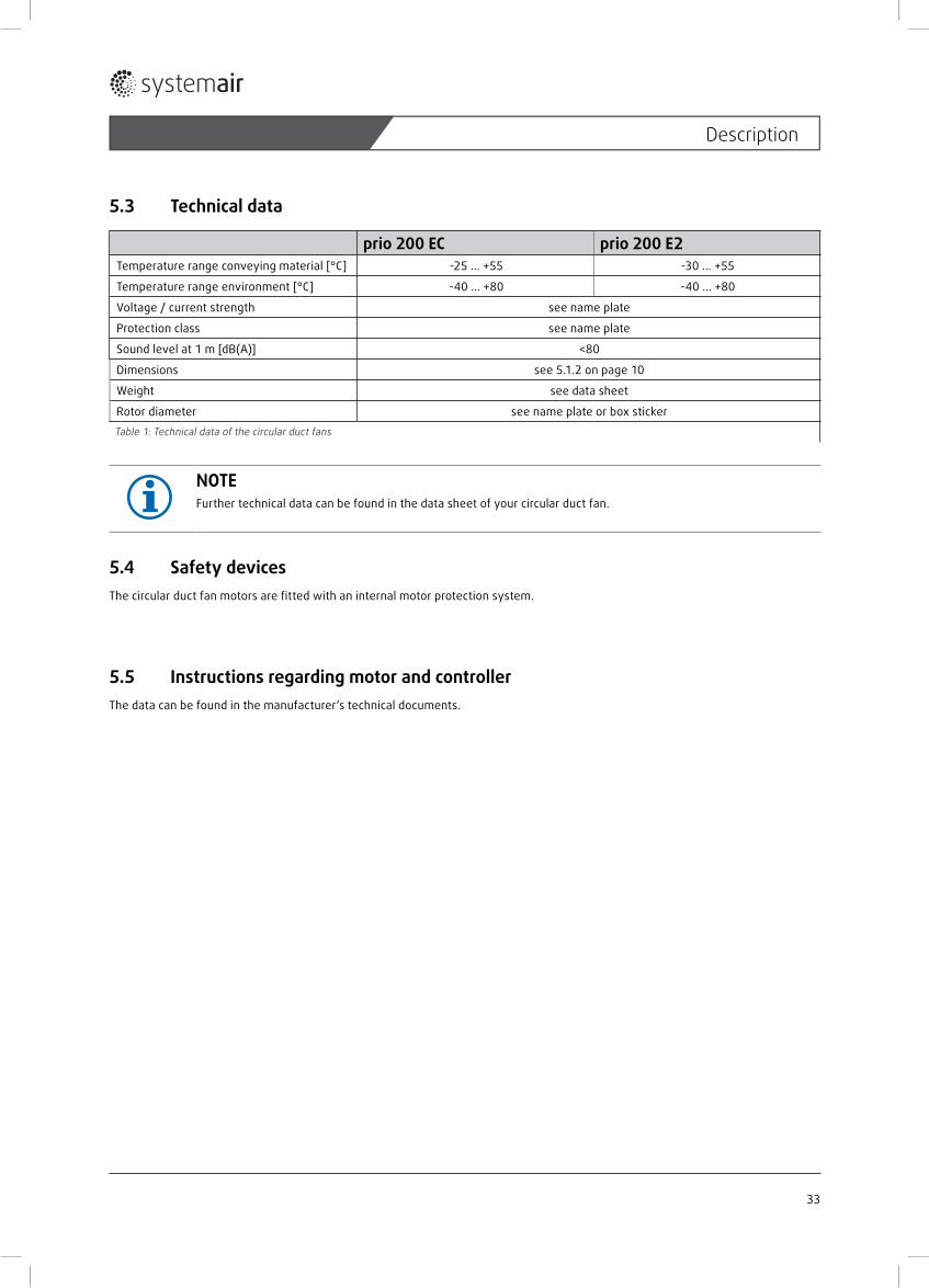
5.3 Technical data
prio 200 EC prio 200 E2Temperature range conveying material [°C] -25 ... +55 -30 ... +55
Temperature range environment [°C] -40 ... +80 -40 ... +80
Voltage / current strength see name plate
Protection class see name plate
Sound level at 1 m [dB(A)] <80
Dimensions see 5.1.2 on page 10
Weight see data sheet
Rotor diameter see name plate or box sticker
Table 1: Technical data of the circular duct fans
NOTEFurther technical data can be found in the data sheet of your circular duct fan.
5.4 Safety devicesThe circular duct fan motors are fi tted with an internal motor protection system.
5.5 Instructions regarding motor and controllerThe data can be found in the manufacturer‘s technical documents.
33
Description
6 Installation
6.1 Safety information• Mounting may only be carried out by trained, qualifi ed personnel.• Comply with the system-related conditions and the requirements of the system manufacturer or plant builder.• Safety components, e.g. protective grids, may not be dismantled or circumvented or put out of function.
6.2 Preconditions for installation
WARNINGDanger of impact from parts of fans dropping! » Check the base before installation for load capacity/strength. » When selecting the fi tting material observe the weight, tendency to vibrations and shear forces (weight informa-
tion on the name plate)..
• Place of installation protected against dust, moisture and weather infl uences.• The installation position can be selected freely (horizontal or vertical). • Ensure safe access to the duct fan for maintenance and repair work.• Provide for contact and intake protection and safety distances according to DIN EN ISO 13857.• Ensure uninhibited and constant infl ow into the appliance and free blow-out.
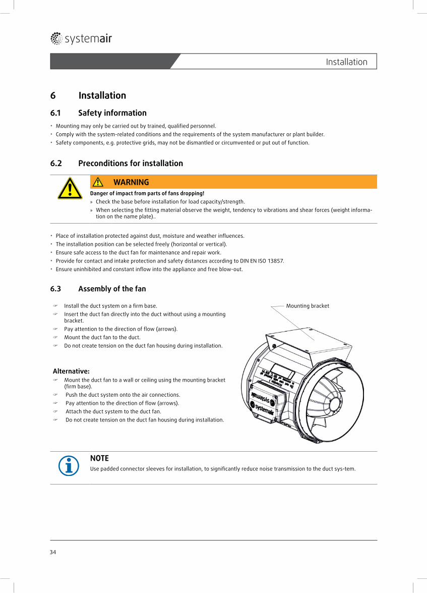
6.3 Assembly of the fan
Install the duct system on a fi rm base. Insert the duct fan directly into the duct without using a mounting
bracket. Pay attention to the direction of fl ow (arrows). Mount the duct fan to the duct. Do not create tension on the duct fan housing during installation.
Alternative: Mount the duct fan to a wall or ceiling using the mounting bracket
(fi rm base). Push the duct system onto the air connections. Pay attention to the direction of fl ow (arrows). Attach the duct system to the duct fan. Do not create tension on the duct fan housing during installation.
Mounting bracket
NOTEUse padded connector sleeves for installation, to signifi cantly reduce noise transmission to the duct sys-tem.
34
Installation

7 Electrical connection
WARNINGHazard from electrical voltage! » Electrical connection only by a trained electrician or trained and instructed qualifi ed personnel! » Electrical connection in accordance with the valid regulations. » Prevent the ingress of water into the connection box/service switch. » Observe 5 safety rules for the electrical expert!
– disconnect from the power supply (all-pole), – prevent switching on again, – test absence of voltage, – earthing and short-circuiting, – protect adjacent live parts by covers and barriers and fi t a suitable warning notice.
Make the electrical connections according to the wiring diagram- prio 200 E2 see fi gure 5- prio 200 EC see fi gure 6.
Arrange the connecting wires in the switch box in such way that the cover can be closed without resistance. Use all cover screws. Apply screws by hand to avoid damage to the thread.
7.1 Wiring diagram prio 200 E2
Color Function/pin assignment
blue L Power supply 230 V AC, 50 ... 60 Hz
black N Neutral conductor
green/yellow
PE Protective conductor
Fig. 5: Wiring diagram of the prio 200 E2
35
Electrical connection
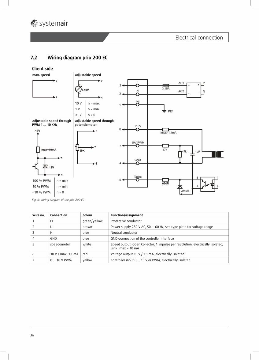
7.2 Wiring diagram prio 200 EC
Client sidemax. speed adjustable speed
10 V n = max
1 V n = min
<1 V n = 0
adjustable speed through PWM 1 ... 10 KHz
adjustable speed through potentiometer
100 % PWM n = max
10 % PWM n = min
<10 % PWM n = 0
Fig. 6: Wiring diagram of the prio 200 EC
Wire no. Connection Colour Function/assignment
1 PE green/yellow Protective conductor
2 L brown Power supply 230 V AC, 50 ... 60 Hz, see type plate for voltage range
3 N blue Neutral conductor
4 GND blue GND-connection of the controller interface
5 speedometer white Speed output: Open Collector, 1 impulse per revolution, electrically isolated, Isink_max = 10 mA
6 10 V / max. 1.1 mA red Voltage output 10 V / 1.1 mA, electrically isolated
7 0 ... 10 V PWM yellow Controller input 0 ... 10 V or PWM, electrically isolated
36
Electrical connection
8 Commissioning
8.1 Preconditions• Mounting and electrical connection have been correctly performed.• Installation residuals and foreign objects have been removed from the fan.• Inlet and outlet are free.• The safety devices have been fi tted (protection against contact).• Grounding connected.• The cable glands are tight.• Provided mains connection complies with the data on the name plate. • Nominal current (from the name plate) does not exceed the mains data.
8.2 Commissioning
WARNINGHazard from electrical voltage! » Commissioning by trained and instructed qualifi ed personnel only!
Switch the circular duct fan on as planned.
WARNINGHazard from bursting parts! » » When checking the direction of rotation, wear safety goggles.
Check: – the direction of rotation / conveying. The direction of rotation always applies looking at the rotor. – smoothly running
Check, if safety elements e.g. protective guards are fastened.
37
Commissioning
9 Operation
9.1 Safety notes
WARNINGHazard from electrical voltage! » The device may only be operated by persons
– instructed in function and risks, – who have understood handling and can accordingly react.
» Ensure that children cannot operate or play with the device without supervision. » Ensure access only to persons, who can safe handle the device.
9.2 Operating conditions• Do not operate the circular duct fan in an explosion-hazardous atmosphere.• During operation, touching the rotor must not be possible.• Safety components must not be bypassed or put out of function.• The circular duct fan may operate inside limits declared on the nameplate. • Prevent suction of foreign particles, this can destroy the fan.• Sound development can be reduced by using a sound fi lter.
9.3 Operation/use Operate the circular duct fan only in accordance with the instructions in this manual and the applicable documents. Control the circular duct fan during operation for correct function. Switch the circular duct fan off as planned.
WARNINGHazard from electrical voltage and fl ying parts!Errors occurring can lead to personal and/or property damage!
Switch the circular duct fan off as planned: » in cases of a non-typical noise from bearings, vibrations, pressure pulsation. » in case of overcurrent, overvoltage or temperature (nameplate).
38
Operation
10 Maintenance/troubleshooting
WARNINGHazard from electrical voltage! » Trouble setting and service only by a trained electrician or trained and instructed qualifi ed personnel! » Observe rules for safe work while troubleshooting! » Observe 5 safety rules for the electrical expert!
– disconnect from the power supply (all-pole), – prevent switching on again, – test absence of voltage, – earthing and short-circuiting, – protect adjacent live parts by covers and barriers.
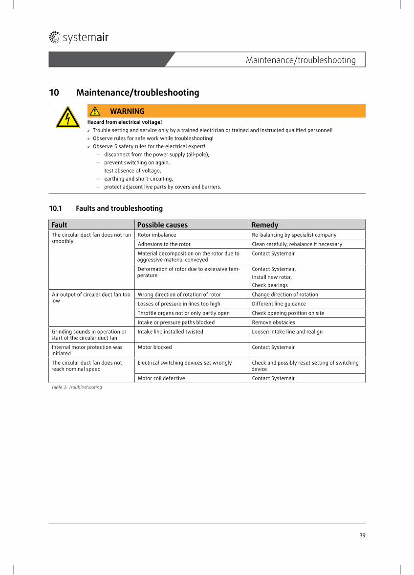
10.1 Faults and troubleshooting
Fault Possible causes RemedyThe circular duct fan does not run smoothly
Rotor imbalance Re-balancing by specialist company
Adhesions to the rotor Clean carefully, rebalance if necessary
Material decomposition on the rotor due to aggressive material conveyed
Contact Systemair
Deformation of rotor due to excessive tem-perature
Contact Systemair,Install new rotor,Check bearings
Air output of circular duct fan too low
Wrong direction of rotation of rotor Change direction of rotation
Losses of pressure in lines too high Different line guidance
Throttle organs not or only partly open Check opening position on site
Intake or pressure paths blocked Remove obstacles
Grinding sounds in operation or start of the circular duct fan
Intake line installed twisted Loosen intake line and realign
Internal motor protection was initiated
Motor blocked Contact Systemair
The circular duct fan does not reach nominal speed
Electrical switching devices set wrongly Check and possibly reset setting of switching device
Motor coil defective Contact Systemair
Table 2: Troubleshooting
39
Maintenance/troubleshooting
10.2 CleaningRegular cleaning of the circular duct fan prevents unbalance.
WARNINGHazard from electrical voltage! » Interior cleaning of the circular duct fan only by a trained electrician or trained and instructed qualifi ed personnel! » Observe rules for safe work while troubleshooting! » Observe 5 safety rules for the electrical expert!
– disconnect from the power supply (all-pole), – prevent switching on again, – test absence of voltage, – earthing and short-circuiting, – protect adjacent live parts by covers and barriers.
CAUTIONDanger from hot surfaces! » During maintenance and cleaning wear protective gloves!
Keep the airways of the circular duct fan clean and clean them if necessary with a brush. Do not use a steel brush.
Do not use a high-pressure cleaner (“steam jet cleaner”) under any circumstances. Do not bend the fan blades when cleaning. Do not use any detergents for interior cleaning.
10.3 Maintenance, serviceThe fan is by built-in for-life lubricated ball bearings as far as possible low-maintenance product. After their life time (app. 30.000 to 40.000 h), a replacement of the bearings is necessary.
WARNINGHazard from electrical voltage!Observe at maintenance and service: » Rotor must stand still.. » Electrical circuit must be interrupted and secured against restarting. » Observe the rules for safe work.
Pay attention to a non-typical noise from bearings. For replacement use only original ball bearings (special grease) of Systemair. For all other damages (e.g. damage to winding) please contact our Service Department. Defective circular duct fans must be
replaced completely. Repairs may be accomplished only in the company of manufacturer and by the manufacturer. You fi nd the address on the back of these operating instructions.
10.4 Spare partsIn case of order of spare parts please specify the type description of the circular duct fan. You can fi nd it on the name plate.
40
Maintenance/troubleshooting
11 Uninstalling/dismounting
WARNINGHazard from electrical voltage! » Switching off and de-installation only by a trained electrician or trained and instructed qualifi ed personnel! » Observe 5 safety rules for the electrical expert!
– disconnect from the power supply (all-pole),– prevent switching on again,– test absence of voltage,– earthing and short-circuiting,– protect adjacent live parts by covers and barriers.
Carefully disconnect all the electrical lines. Separate the circular duct fan from the supply connections.
CAUTIONGefährdung durch Stoß und Schneiden! » Wear protective gloves when dismounting! » Dismount carefully..
Carefully remove the fastening material. Place the circular duct fan on the fl oor.
12 DisposalBoth the appliance and also the matching transport packaging predominantly comprise recycling-capable raw materials.
12.1 Disposal of the circular duct fanShould the circular duct fan be disposed, proceed as follows:
Switch the circular duct fan free of voltage. Disconnect the circular duct fan from the supply connections. Disassemble the circular duct fan into its components. Separate the parts according to– reusable material– material groups to be disposed (metal, plastics, electrical parts, etc.)
Provide for the recycling of material. Consider the national regulation.
12.2 Disposal of packaging Provide for the recycling of material. Consider the national regulation.
41
Uninstalling/dismounting
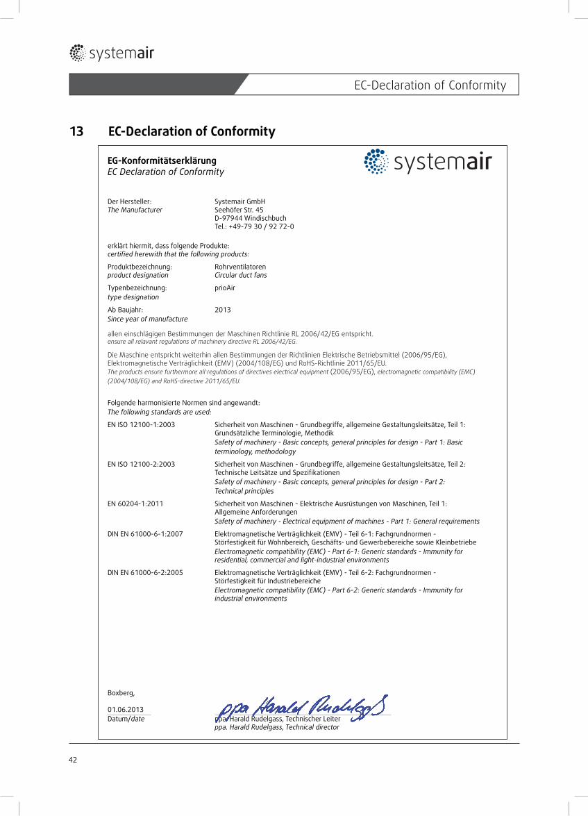
13 EC-Declaration of Conformity
EG-KonformitätserklärungEC Declaration of Conformity
Der Hersteller: Systemair GmbHThe Manufacturer Seehöfer Str. 45
D-97944 WindischbuchTel.: +49-79 30 / 92 72-0
erklärt hiermit, dass folgende Produkte:certified herewith that the following products:
Produktbezeichnung: Rohrventilatorenproduct designation Circular duct fans
Typenbezeichnung: prioAirtype designation
Ab Baujahr: 2013Since year of manufacture
allen einschlägigen Bestimmungen der Maschinen Richtlinie RL 2006/42/EG entspricht.ensure all relavant regulations of machinery directive RL 2006/42/EG.
Die Maschine entspricht weiterhin allen Bestimmungen der Richtlinien Elektrische Betriebsmittel (2006/95/EG), Elektromagnetische Verträglichkeit (EMV) (2004/108/EG) und RoHS-Richtlinie 2011/65/EU. The products ensure furthermore all regulations of directives electrical equipment (2006/95/EG), electromagnetic compatibility (EMC) (2004/108/EG) and RoHS-directive 2011/65/EU.
Folgende harmonisierte Normen sind angewandt:The following standards are used:
EN ISO 12100-1:2003 Sicherheit von Maschinen - Grundbegriffe, allgemeine Gestaltungsleitsätze, Teil 1: Grundsätzliche Terminologie, MethodikSafety of machinery - Basic concepts, general principles for design - Part 1: Basic terminology, methodology
EN ISO 12100-2:2003 Sicherheit von Maschinen - Grundbegriffe, allgemeine Gestaltungsleitsätze, Teil 2: TechnischeLeitsätzeundSpezifikationenSafety of machinery - Basic concepts, general principles for design - Part 2: Technical principles
EN 60204-1:2011 Sicherheit von Maschinen - Elektrische Ausrüstungen von Maschinen, Teil 1: Allgemeine AnforderungenSafety of machinery - Electrical equipment of machines - Part 1: General requirements
DIN EN 61000-6-1:2007 Elektromagnetische Verträglichkeit (EMV) - Teil 6-1: Fachgrundnormen - Störfestigkeit für Wohnbereich, Geschäfts- und Gewerbebereiche sowie KleinbetriebeElectromagnetic compatibility (EMC) - Part 6-1: Generic standards - Immunity for residential, commercial and light-industrial environments
DIN EN 61000-6-2:2005 Elektromagnetische Verträglichkeit (EMV) - Teil 6-2: Fachgrundnormen - Störfestigkeit für IndustriebereicheElectromagnetic compatibility (EMC) - Part 6-2: Generic standards - Immunity for industrial environments
Boxberg,
01.06.2013 Datum/date ppa. Harald Rudelgass, Technischer Leiter
ppa. Harald Rudelgass, Technical director
42
EC-Declaration of Conformity
Notes
43
Systemair GmbH • Seehöfer Str. 45 • D-97944 Windischbuch Tel.: +49 (0)7930/9272-0 • Fax: +49 (0)7930/9273-92
3130
47 /
Jun
i 201
3


![[XLS]Systemair Price List 2018 - Systemair в Украине · Web viewua Item number Name KVO 100 Circular duct fan KVO 125 Circular duct fan KVO 160 Circular duct fan KVO 200 Circular](https://static.documents.pub/doc/80x56/5b4087de7f8b9aff118d6108/xlssystemair-price-list-2018-systemair-web-viewua-item.jpg)


