27
© 2016 Cisco and/or its affiliates. All rights reserved. This document is Cisco Public Information. Page 1 of 27 White Paper Cisco Data Center Spine-and-Leaf Architecture: Design Overview
© 2016 Cisco and/or its affiliates. All rights reserved. This document is Cisco Public Information. Page 1 of 27
White Paper
Cisco Data Center Spine-and-Leaf Architecture: Design Overview

© 2016 Cisco and/or its affiliates. All rights reserved. This document is Cisco Public Information. Page 2 of 27
Contents
Data Center Evolution ............................................................................................................................................. 3 Spine-and-Leaf Architecture ................................................................................................................................... 4 Overlay Network ...................................................................................................................................................... 5 Cisco FabricPath Spine-and-Leaf Network ............................................................................................................ 6
Encapsulation Format and Standards Compliance ............................................................................................... 6 Underlay Network ............................................................................................................................................. 7 Overlay Network ............................................................................................................................................... 7
Broadcast and Unknown Unicast Traffic ............................................................................................................... 7 Host Detection and Reachability ........................................................................................................................... 7 Multicast Traffic ..................................................................................................................................................... 7 Layer 3 Routing Function ...................................................................................................................................... 7
Internal and External Routing at the Border Spine ............................................................................................ 8 Internal and External Routing at the Border Leaf .............................................................................................. 8
Multitenancy .......................................................................................................................................................... 9 Cisco FabricPath Spine-and-Leaf Network Summary ......................................................................................... 10
Cisco VXLAN Flood-and-Learn Spine-and-Leaf Network ................................................................................... 11 Encapsulation Format and Standards Compliance ............................................................................................. 11
Underlay Network ........................................................................................................................................... 11 Overlay Network ............................................................................................................................................. 12
Broadcast and Unknown Unicast Traffic ............................................................................................................. 13 Host Detection and Reachability ......................................................................................................................... 13 Multicast Traffic ................................................................................................................................................... 13 Layer 3 Routing Function .................................................................................................................................... 13
Internal and External Routing on the Spine Layer ........................................................................................... 13 Internal and External Routing on the Border Leaf ........................................................................................... 14
Multitenancy ........................................................................................................................................................ 15 Cisco VXLAN Flood-and-Learn Spine-and-Leaf Network Summary ................................................................... 16
Cisco VXLAN MP-BGP EVPN Spine-and-Leaf Network ...................................................................................... 17 Encapsulation Format and Standards Compliance ............................................................................................. 17
Underlay Network ........................................................................................................................................... 17 Overlay Network ............................................................................................................................................. 17
Broadcast and Unknown Unicast Traffic ............................................................................................................. 17 Host Detection and Reachability ......................................................................................................................... 17 Multicast Traffic ................................................................................................................................................... 18 Layer 3 Routing Function .................................................................................................................................... 18
Distributed Anycast Gateway for Internal Routing ........................................................................................... 18 External Routing at the Border Leaf ................................................................................................................ 19 External Routing at the Border Spine .............................................................................................................. 19
Multitenancy ........................................................................................................................................................ 20 Cisco VXLAN MP BGP-EVPN Spine-and-Leaf Network Summary ..................................................................... 21
Cisco MSDC Layer 3 Spine-and-Leaf Network .................................................................................................... 22 Data Center Fabric Management and Automation .............................................................................................. 23
Cisco Prime Data Center Network Manager ....................................................................................................... 23 Cisco Virtual Topology System ........................................................................................................................... 24 Ignite ................................................................................................................................................................... 24
Conclusion ............................................................................................................................................................. 24 Cisco Spine-and-Leaf Layer 2 and Layer 3 Fabric Comparison .......................................................................... 25
For More Information ............................................................................................................................................. 27
© 2016 Cisco and/or its affiliates. All rights reserved. This document is Cisco Public Information. Page 3 of 27
Data Center Evolution
The data center is at the foundation of modern software technology, serving a critical role in expanding capabilities
for enterprises. The traditional data center uses a three-tier architecture, with servers segmented into pods based
on location, as shown in Figure 1.
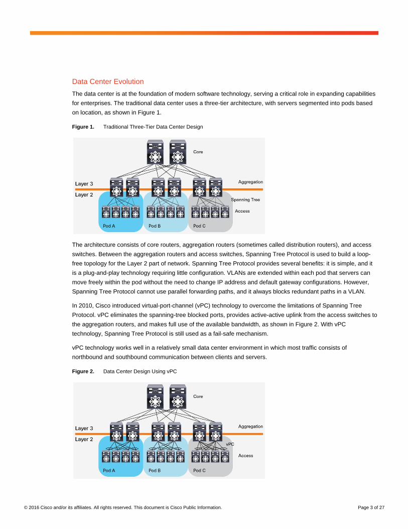
Figure 1. Traditional Three-Tier Data Center Design
The architecture consists of core routers, aggregation routers (sometimes called distribution routers), and access
switches. Between the aggregation routers and access switches, Spanning Tree Protocol is used to build a loop-
free topology for the Layer 2 part of network. Spanning Tree Protocol provides several benefits: it is simple, and it
is a plug-and-play technology requiring little configuration. VLANs are extended within each pod that servers can
move freely within the pod without the need to change IP address and default gateway configurations. However,
Spanning Tree Protocol cannot use parallel forwarding paths, and it always blocks redundant paths in a VLAN.
In 2010, Cisco introduced virtual-port-channel (vPC) technology to overcome the limitations of Spanning Tree
Protocol. vPC eliminates the spanning-tree blocked ports, provides active-active uplink from the access switches to
the aggregation routers, and makes full use of the available bandwidth, as shown in Figure 2. With vPC
technology, Spanning Tree Protocol is still used as a fail-safe mechanism.
vPC technology works well in a relatively small data center environment in which most traffic consists of
northbound and southbound communication between clients and servers.
Figure 2. Data Center Design Using vPC

© 2016 Cisco and/or its affiliates. All rights reserved. This document is Cisco Public Information. Page 4 of 27
Since 2003, with the introduction of virtual technology, the computing, networking, and storage resources that were
segregated in pods in Layer 2 in the three-tier data center design can be pooled. This revolutionary technology
created a need for a larger Layer 2 domain, from the access layer to the core layer, as shown in Figure 3.
Figure 3. Data Center Design with Extended Layer 3 Domain
With Layer 2 segments extended across all the pods, the data center administrator can create a central, more
flexible resource pool that can be reallocated based on needs. Servers are virtualized into sets of virtual machines
that can move freely from server to server without the need to change their operating parameters.
With virtualized servers, applications are increasingly deployed in a distributed fashion, which leads to increased
east-west traffic. This traffic needs to be handled efficiently, with low and predictable latency. However, vPC can
provide only two active parallel uplinks, and so bandwidth becomes a bottleneck in a three-tier data center
architecture. Another challenge in a three-tier architecture is that server-to-server latency varies depending on the
traffic path used.
A new data center design called the Clos network–based spine-and-leaf architecture was developed to overcome
these limitations. This architecture has been proven to deliver the high-bandwidth, low-latency, nonblocking server-
to-server connectivity.
Spine-and-Leaf Architecture
Figure 4 shows a typical two-tiered spine-and-leaf topology.
Figure 4. Typical Spine-and-Leaf Topology

© 2016 Cisco and/or its affiliates. All rights reserved. This document is Cisco Public Information. Page 5 of 27
In this two-tier Clos architecture, every lower-tier switch (leaf layer) is connected to each of the top-tier switches
(spine layer) in a full-mesh topology. The leaf layer consists of access switches that connect to devices such as
servers. The spine layer is the backbone of the network and is responsible for interconnecting all leaf switches.
Every leaf switch connects to every spine switch in the fabric. The path is randomly chosen so that the traffic load
is evenly distributed among the top-tier switches. If one of the top tier switches were to fail, it would only slightly
degrade performance throughout the data center.
If oversubscription of a link occurs (that is, if more traffic is generated than can be aggregated on the active link at
one time), the process for expanding capacity is straightforward. An additional spine switch can be added, and
uplinks can be extended to every leaf switch, resulting in the addition of interlayer bandwidth and reduction of the
oversubscription. If device port capacity becomes a concern, a new leaf switch can be added by connecting it to
every spine switch and adding the network configuration to the switch. The ease of expansion optimizes the IT
department’s process of scaling the network. If no oversubscription occurs between the lower-tier switches and
their uplinks, then a nonblocking architecture can be achieved.
With a spine-and-leaf architecture, no matter which leaf switch to which a server is connected, its traffic always has
to cross the same number of devices to get to another server (unless the other server is located on the same leaf).
This approach keeps latency at a predictable level because a payload only has to hop to a spine switch and
another leaf switch to reach its destination.
Overlay Network
Modern virtualized data center fabrics must meet certain requirements to accelerate application deployment and
support DevOps needs. For example, fabrics need to support scaling of forwarding tables, scaling of network
segments, Layer 2 segment extension, virtual device mobility, forwarding path optimization, and virtualized
networks for multitenant support on shared physical infrastructure.
Although the concept of a network overlay is not new, interest in network overlays has increased in the past few
years because of their potential to address some of these requirements. Interest in overlay networks has also
increased with the introduction of new encapsulation frame formats specifically built for the data center. These
formats include Virtual Extensible LAN (VXLAN), Network Virtualization Using Generic Routing Encapsulation
(NVGRE), Transparent Interconnection of Lots of Links (TRILL), and Location/Identifier Separation Protocol (LISP).
Network overlays are virtual networks of interconnected nodes that share an underlying physical network, allowing
deployment of applications that require specific network topologies without the need to modify the underlying
network (Figure 5).
Figure 5. Network Overlay Concept
© 2016 Cisco and/or its affiliates. All rights reserved. This document is Cisco Public Information. Page 6 of 27
Benefits of a network virtualization overlay include the following:
● Optimized device functions: Overlay networks allow the separation (and specialization) of device
functions based on where a device is being used in the network. An edge or leaf device can optimize its
functions and all its relevant protocols based on end-state information and scale, and a core or spine device
can optimize its functions and protocols based on link-state updates, optimizing with fast convergence.
● Fabric scalability and flexibility: Overlay technologies allow the network to scale by focusing scaling on
the network overlay edge devices. With overlays used at the fabric edge, the spine and core devices are
freed from the need to add end-host information to their forwarding tables.
● Overlapping addressing: Most overlay technologies used in the data center allow virtual network IDs to
uniquely scope and identify individual private networks. This scoping allows potential overlap in MAC and IP
addresses between tenants. The overlay encapsulation also allows the underlying infrastructure address
space to be administered separately from the tenant address space.
This document reviews several spine-and-leaf architecture designs that Cisco has offered in the recent past as well
as current designs and those the Cisco expects to offer in the near future to address fabric requirements in the
modern virtualized data center:
● Cisco® FabricPath spine-and-leaf network
● Cisco VXLAN flood-and-learn spine-and-leaf network
● Cisco VXLAN Multiprotocol Border Gateway Protocol (MP-BGP) Ethernet Virtual Private Network (EVPN)
spine-and-leaf network
● Cisco Massively Scalable Data Center (MSDC) Layer 3 spine-and-leaf network
Each section outlines the most important technology components (encapsulation; end-host detection and
distribution; broadcast, unknown unicast, and multicast traffic forwarding; underlay and overlay control plane,
multitenancy support, etc.), common designs, and design considerations (Layer 3 gateway, etc.) at the time of this
writing.
Cisco FabricPath Spine-and-Leaf Network
Cisco introduced FabricPath technology in 2010. FabricPath enables new capabilities and design options that allow
network operators to create Ethernet fabrics that increase bandwidth availability, provide design flexibility, and
simplify and reduce the costs of network and application deployment and operation. A typical FabricPath network
uses a spine-and-leaf architecture.
FabricPath technology uses many of the best characteristics of traditional Layer 2 and Layer 3 technologies. It
retains the easy-configuration, plug-and-play deployment model of a Layer 2 environment. It also introduces a
control-plane protocol called FabricPath Intermediate System to Intermediate System (IS-IS). This shortest-path
first (SPF) routing protocol is used to determine reachability and select the best path or paths to any given
destination FabricPath switch in the FabricPath network. The result is increased stability and scalability, fast
convergence, and the capability to use multiple parallel paths typical in a Layer 3 routed environment.
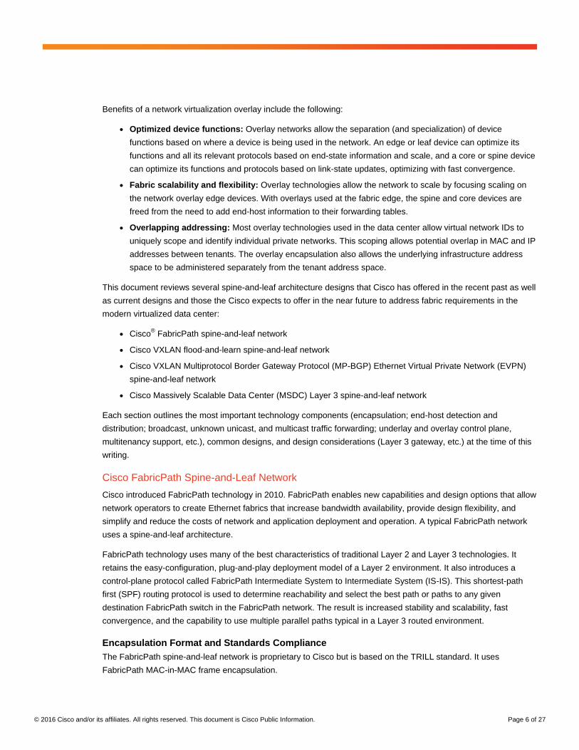
Encapsulation Format and Standards Compliance
The FabricPath spine-and-leaf network is proprietary to Cisco but is based on the TRILL standard. It uses
FabricPath MAC-in-MAC frame encapsulation.
© 2016 Cisco and/or its affiliates. All rights reserved. This document is Cisco Public Information. Page 7 of 27
Underlay Network
The FabricPath spine-and-leaf network uses Layer 2 FabricPath MAC-in-MAC frame encapsulation, and it uses
FabricPath IS-IS for the control-plane in the underlay network. Each FabricPath switch is identified by a FabricPath
switch ID. The FabricPath IS-IS control plane builds reachability information about how to reach other FabricPath
switches.
Overlay Network
FabricPath has no overlay control plane for the overlay network. End-host information in the overlay network is
learned through the flood-and-learn mechanism with conversational learning.
Broadcast and Unknown Unicast Traffic
For a FabricPath network, the FabricPath IS-IS control plane by default creates two multidestination trees that
carry broadcast traffic, unknown unicast traffic, and multicast traffic through the FabricPath network. Broadcast and
unknown unicast traffic in FabricPath is flooded to all FabricPath edge ports in the VLAN or broadcast domain.
Host Detection and Reachability
To learn end-host reachability information, FabricPath switches rely on initial data-plane traffic flooding. As the
number of hosts in a broadcast domain increases, the negative effects of flooding packets are more pronounced.
The impact of broadcast and unknown unicast traffic flooding needs to be carefully considered in the FabricPath
network design. Features exist, such as the FabricPath Multitopology feature, to help limit traffic flooding in a
subsection of the FabricPath network.
Multicast Traffic
For a FabricPath network, the FabricPath IS-IS control plane by default creates two multidestination trees that
carry broadcast traffic, unknown unicast traffic, and multicast traffic through the FabricPath network. IP multicast
traffic is by default constrained to only those FabricPath edge ports that have either an interested multicast receiver
or a multicast router attached and use Internet Group Management Protocol (IGMP) snooping. For Layer 2
multicast traffic, traffic entering the FabricPath switch is hashed to a multidestination tree to be forwarded. For
Layer 3 IP multicast traffic, traffic needs to be forwarded by Layer 3 multicast using Protocol-Independent Multicast
(PIM). After traffic is routed to the destination VLAN, then it is forwarded using the multidestination tree in the
destination VLAN.
Layer 3 Routing Function
FabricPath is a Layer 2 network fabric technology, which allows you to easily scale the network capacity simply by
adding more spine nodes and leaf nodes at Layer 2. But most networks are not pure Layer 2 networks. Servers
may talk with other servers in different subnets or talk with clients in remote branch offices over the WAN or
Internet. That traffic needs to be routed by a Layer 3 function enabled on FabricPath switches (default gateways
and border switches).
The placement of a Layer 3 function in a FabricPath network needs to be carefully designed. Two major design
options are available: internal and external routing at a border spine, and internal and external routing at a border
leaf. Both designs provide centralized routing: that is, the Layer 3 routing functions are centralized on specific
switches.

© 2016 Cisco and/or its affiliates. All rights reserved. This document is Cisco Public Information. Page 8 of 27
Internal and External Routing at the Border Spine
As shown in the design for internal and external routing at the border spine in Figure 6, the spine switch functions
as the Layer 2 and Layer 3 boundary and server subnet gateway. Spine switches are performing intra-VLAN
FabricPath frame switching. The switch virtual interfaces (SVIs) on the spine switch are performing inter-VLAN
routing for east-west internal traffic and exchange routing adjacency information with Layer 3 routed uplinks to
route north-south external traffic. Routed traffic needs to traverse only one hop to reach to default gateway at the
spine switches to be routed.
FabricPath technology currently supports up to four FabricPath anycast gateways. If the spine-and-leaf network
has more than four spine switches, the Layer 2 and Layer 3 boundary needs to be distributed across the spine
switches. Also, with SVIs enabled on the spine switch, the spine switch disables conversational learning and learns
the MAC address in the corresponding subnet. You need to consider MAC address scale to avoid exceeding the
scalability limits of your hardware.
Figure 6. Internal and External Routing at the Border Spine
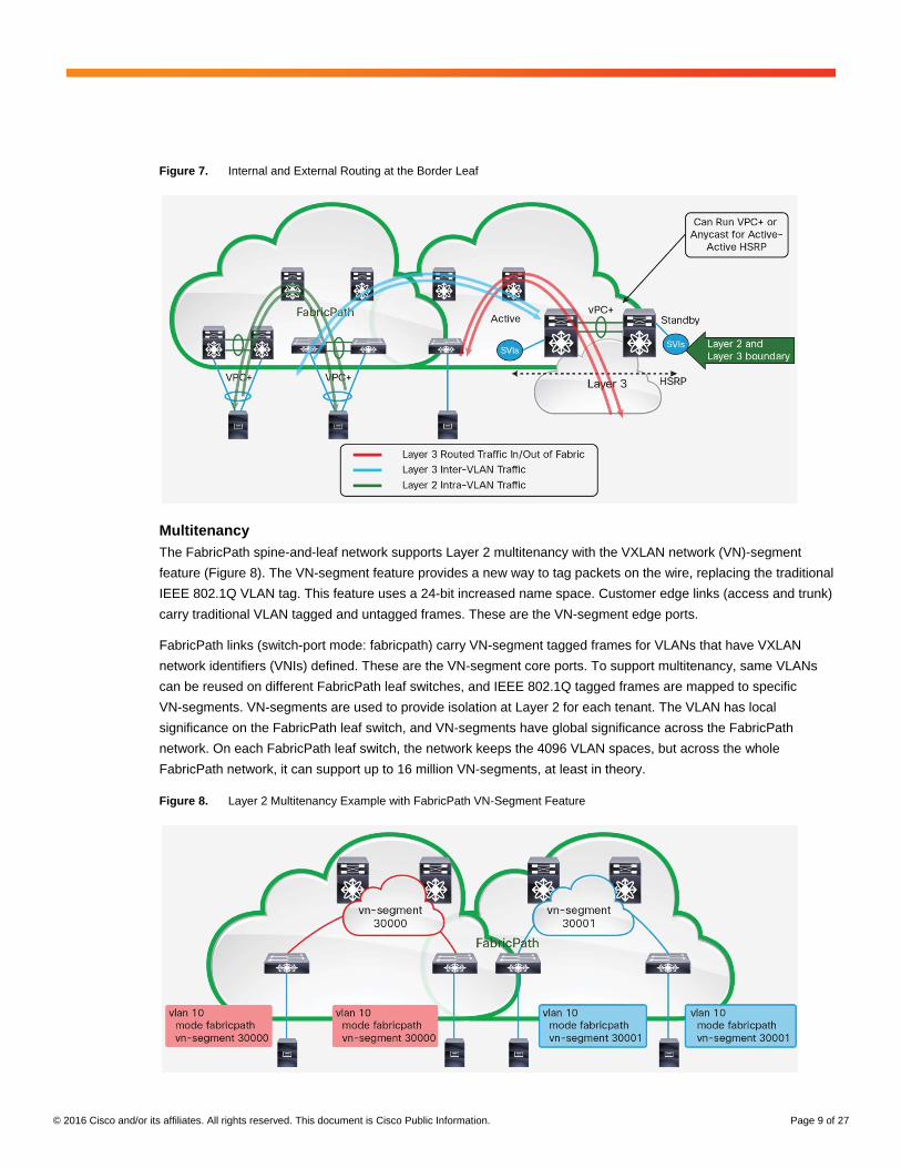
Internal and External Routing at the Border Leaf
As shown in the design for internal and external routing at the border leaf in Figure 7, the spine switch functions as
the Layer 2 FabricPath switch and performs intra-VLAN FabricPath frame switching only. It doesn’t learn host MAC
addresses. The Layer 2 and Layer 3 function is enabled on some FabricPath leaf switches called border leaf
switches. The SVIs on the border leaf switches perform inter-VLAN routing for east-west internal traffic and
exchange routing adjacency with Layer 3 routed uplinks to route north-south external traffic. But routed traffic
needs to traverse two hops: leaf to spine and then to the default gateway on the border leaf to be routed.
Up to four FabricPath anycast gateways can be enabled in the design with routing at the border leaf. You need to
consider MAC address scale to avoid exceeding the scalability limit on the border leaf switch.
© 2016 Cisco and/or its affiliates. All rights reserved. This document is Cisco Public Information. Page 9 of 27
Figure 7. Internal and External Routing at the Border Leaf
Multitenancy
The FabricPath spine-and-leaf network supports Layer 2 multitenancy with the VXLAN network (VN)-segment
feature (Figure 8). The VN-segment feature provides a new way to tag packets on the wire, replacing the traditional
IEEE 802.1Q VLAN tag. This feature uses a 24-bit increased name space. Customer edge links (access and trunk)
carry traditional VLAN tagged and untagged frames. These are the VN-segment edge ports.
FabricPath links (switch-port mode: fabricpath) carry VN-segment tagged frames for VLANs that have VXLAN
network identifiers (VNIs) defined. These are the VN-segment core ports. To support multitenancy, same VLANs
can be reused on different FabricPath leaf switches, and IEEE 802.1Q tagged frames are mapped to specific
VN-segments. VN-segments are used to provide isolation at Layer 2 for each tenant. The VLAN has local
significance on the FabricPath leaf switch, and VN-segments have global significance across the FabricPath
network. On each FabricPath leaf switch, the network keeps the 4096 VLAN spaces, but across the whole
FabricPath network, it can support up to 16 million VN-segments, at least in theory.
Figure 8. Layer 2 Multitenancy Example with FabricPath VN-Segment Feature

© 2016 Cisco and/or its affiliates. All rights reserved. This document is Cisco Public Information. Page 10 of 27
The FabricPath spine-and-leaf network also supports Layer 3 multitenancy using Virtual Routing and Forwarding
lite (VRF-lite), as shown in Figure 9. The FabricPath network is a Layer 2 network, and Layer 3 SVIs are laid on top
of the Layer 2 FabricPath switch. With VRF-lite, the number of VLANs supported across the FabricPath network is
4096.
Figure 9. Layer 3 Multitenancy Example with VRF-lite
Cisco FabricPath Spine-and-Leaf Network Summary
The FabricPath spine-and-leaf network is proprietary to Cisco, but it is mature technology and has been widely
deployed. It provides a simple, flexible, and stable network, with good scalability and fast convergence
characteristics, and it can use multiple parallel paths at Layer 2. But the FabricPath network is flood-and-learn-
based Layer 2 technology. Its control-plane protocol, FabricPath IS-IS, is designed to determine FabricPath switch
ID reachability information. To learn end-host reachability information, FabricPath switches rely on initial data-plane
traffic flooding. As the number of hosts in a broadcast domain increases, the negative effects of flooding packets
become more pronounced. A Layer 3 function is laid on top of the Layer 2 network. Common Layer 3 designs use
centralized routing: that is, the Layer 3 routing function is centralized on specific switches (spine switches or border
leaf switches). The FabricPath network supports up to four anycast gateways for internal VLAN routing.
Table 1 summarizes the characteristics of a FabricPath spine-and-leaf network.
Table 1. Cisco FabricPath Network Characteristics
Item Description
Transport medium Layer 1
Encapsulation FabricPath (MAC-in-MAC frame encapsulation)
Unique node identifier FabricPath switch ID
End-host detection Flood and learn
Silent host discovery Yes
End-host reachability and distribution Flood and learn plus conversational learning
Broadcast and unknown unicast traffic Flood by FabricPath IS-IS multidestination tree
Underlay control plane FabricPath IS-IS
Overlay control plane –
Layer 3 routing function ● Internal and external routing at border spine
● Internal and external routing at border leaf
● Up to 4 FabricPath anycast gateways supported

© 2016 Cisco and/or its affiliates. All rights reserved. This document is Cisco Public Information. Page 11 of 27
Item Description
Multicast traffic Supports:
● Layer 2 multicast traffic (forwarded by multidestination tree)
● Layer 3 IP multicast traffic (forwarded by Layer 3 multicast using PIM)
Multitenancy ● Layer 2 multitenancy with VN-segment
● Layer 3 multitenancy with VRF-lite
Standard reference TRILL based (Cisco proprietary)
Supported hardware ● Cisco Nexus® 7000 Series Switches including the Cisco Nexus 7700 platform switches
● Cisco Nexus 5500 and 5600 platform switches
● Cisco Nexus 6000 Series Switches
For feature support and for more information about Cisco FabricPath technology, please refer to the configuration
guides, release notes, and reference documents listed at the end of this document.
Cisco VXLAN Flood-and-Learn Spine-and-Leaf Network
VXLAN, one of many available network virtualization overlay technologies, offers several advantages. It is an
industry-standard protocol and uses underlay IP networks. It extends Layer 2 segments over a Layer 3
infrastructure to build Layer 2 overlay logical networks. It encapsulates Ethernet frames into IP User Data Protocol
(UDP) headers and transports the encapsulated packets through the underlay network to the remote VXLAN tunnel
endpoints (VTEPs) using the normal IP routing and forwarding mechanism. Cisco began supporting VXLAN flood-
and-learn spine-and-leaf technology in about 2014 on multiple Cisco Nexus switches such as the Cisco Nexus
5600 platform and Cisco Nexus 7000 and 9000 Series. This section describes Cisco VXLAN flood-and-learn
characteristic on these Cisco hardware switches.
Encapsulation Format and Standards Compliance
Cisco VXLAN flood-and-learn technology complies with the IETF VXLAN standards (RFC 7348), which defined a
multicast-based flood-and-learn VXLAN without a control plane. The original Layer 2 frame is encapsulated with a
VXLAN header and then placed in a UDP-IP packet and transported across an IP network.
Underlay Network
The VXLAN flood-and-learn spine-and-leaf network uses Layer 3 IP for the underlay network. Underlay IP multicast
is used to reduce the flooding scope of the set of hosts that are participating in the VXLAN segment. Each VXLAN
segment has a VXLAN network identifier (VNID), and the VNID is mapped to an IP multicast group in the transport
IP network. Each VTEP device is independently configured with this multicast group and participates in PIM
routing. The multicast distribution tree for this group is built through the transport network based on the locations of
participating VTEPs. The requirement to enable multicast capabilities in the underlay network presents a challenge
to some organizations because they do not want to enable multicast in their data centers or WANs.
The Cisco Nexus 9000 Series introduced an ingress replication feature, so the underlay network is multicast free.
The VXLAN VTEP uses a list of IP addresses of other VTEPs in the network to send broadcast and unknown
unicast traffic. These IP addresses are exchanged between VTEPs through the static ingress replication
configuration (Figure 10).

© 2016 Cisco and/or its affiliates. All rights reserved. This document is Cisco Public Information. Page 12 of 27
Figure 10. VXLAN IP Underlay Network
Overlay Network
The VXLAN flood-and-learn spine-and-leaf network doesn’t have a control plane for the overlay network. The Layer
2 overlay network is created on top of the Layer 3 IP underlay network by using the VTEP tunneling mechanism to
transport Layer 2 packets. The overlay network uses flood-and-learn semantics (Figure 11).
Figure 11. VXLAN Overlay Network
© 2016 Cisco and/or its affiliates. All rights reserved. This document is Cisco Public Information. Page 13 of 27
Broadcast and Unknown Unicast Traffic
Underlay IP PIM or the ingress replication feature is used to send broadcast and unknown unicast traffic. Note that
the ingress replication feature is supported only on Cisco Nexus 9000 Series Switches.
Host Detection and Reachability
The VXLAN flood-and-learn spine-and-leaf network relies on initial data-plane traffic flooding to enable VTEPs to
discover each other and to learn remote host MAC addresses and MAC-to-VTEP mappings for each VXLAN
segment. After MAC-to-VTEP mapping is complete, the VTEPs forward VXLAN traffic in a unicast stream.
Multicast Traffic
In a VXLAN flood-and-learn spine-and-leaf network, overlay tenant Layer 2 multicast traffic is supported using
underlay IP PIM or the ingress replication feature. Note that ingress replication is supported only on Cisco Nexus
9000 Series Switches.
Layer 3 IP multicast traffic is forwarded by Layer 3 PIM-based multicast routing.
Multicast group scaling needs to be designed carefully. Ideally, you should map one VXLAN segment to one IP
multicast group to provide optimal multicast forwarding. You can also have multiple VXLAN segments share a
single IP multicast group in the core network; however, the overloading of multicast groups leads to suboptimal
multicast forwarding.
Layer 3 Routing Function
As in a traditional VLAN environment, routing between VXLAN segments or from a VXLAN segment to a VLAN
segment is required in many situations. In a typical VXLAN flood-and-learn spine-and-leaf network design, the leaf
top-of-rack (ToR) switches are enabled as VTEP devices to extend the Layer 2 segments between racks. These
VTEPs are Layer 2 VXLAN gateways for VXLAN-to-VLAN or VLAN-to-VXLAN bridging. When traffic needs to be
routed between VXLAN segments or from a VXLAN segment to a VLAN segment and vice visa, the Layer 3
VXLAN gateway function needs to be enabled on some VTEPs. The common designs used are internal and
external routing on the spine layer, and internal and external routing on the leaf layer. Both designs provide
centralized routing: that is, the Layer 3 internal and external routing functions are centralized on specific switches.
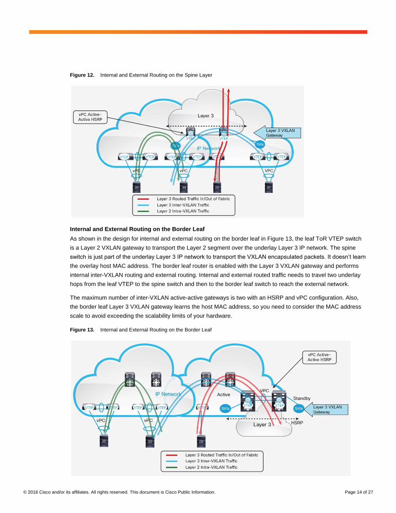
Internal and External Routing on the Spine Layer
As shown in the design for internal and external routing on the spine layer in Figure 12, the leaf ToR VTEP switch
is a Layer 2 VXLAN gateway to transport the Layer 2 segment over the underlay Layer 3 IP network. The spine
switch has two functions. It is part of the underlay Layer 3 IP network and transports the VXLAN encapsulated
packets. It also performs internal inter-VXLAN routing and external routing. Internal and external routed traffic
needs to travel one underlay hop from the leaf VTEP to the spine switch to be routed.
Note that the maximum number of inter-VXLAN active-active gateways is two with a Hot-Standby Router Protocol
(HSRP) and vPC configuration. Also, the spine Layer 3 VXLAN gateway learns the host MAC address, so you
need to consider the MAC address scale to avoid exceeding the scalability limits of your hardware.
© 2016 Cisco and/or its affiliates. All rights reserved. This document is Cisco Public Information. Page 14 of 27
Figure 12. Internal and External Routing on the Spine Layer
Internal and External Routing on the Border Leaf
As shown in the design for internal and external routing on the border leaf in Figure 13, the leaf ToR VTEP switch
is a Layer 2 VXLAN gateway to transport the Layer 2 segment over the underlay Layer 3 IP network. The spine
switch is just part of the underlay Layer 3 IP network to transport the VXLAN encapsulated packets. It doesn’t learn
the overlay host MAC address. The border leaf router is enabled with the Layer 3 VXLAN gateway and performs
internal inter-VXLAN routing and external routing. Internal and external routed traffic needs to travel two underlay
hops from the leaf VTEP to the spine switch and then to the border leaf switch to reach the external network.
The maximum number of inter-VXLAN active-active gateways is two with an HSRP and vPC configuration. Also,
the border leaf Layer 3 VXLAN gateway learns the host MAC address, so you need to consider the MAC address
scale to avoid exceeding the scalability limits of your hardware.
Figure 13. Internal and External Routing on the Border Leaf

© 2016 Cisco and/or its affiliates. All rights reserved. This document is Cisco Public Information. Page 15 of 27
Multitenancy
The VXLAN flood-and-learn spine-and-leaf network supports Layer 2 multitenancy (Figure 14). VXLAN uses a 24-
bit segment ID, or VNID, which enables up to 16 million VXLAN segments to coexist in the same administrative
domain. To support multitenancy, the same VLAN can be reused on different VTEP switches, and IEEE 802.1Q
tagged frames received on VTEPs are mapped to specific VNIs. VNIs are used to provide isolation at Layer 2 for
each tenant. VLAN has local significance on the leaf VTEP switch, and the VNI has global significance across the
VXLAN network.
Figure 14. Layer 2 Multitenancy Example Using the VNI
The VXLAN flood-and-learn spine-and-leaf network also supports Layer 3 multitenancy using VRF-lite (Figure 15).
The VXLAN flood-and-learn network is a Layer 2 overlay network, and Layer 3 SVIs are laid on top of the Layer 2
overlay network. With VRF-lite, the number of VLANs supported across the VXLAN flood-and-learn network is
4096.
Figure 15. Layer 3 Multitenancy Example Using VRF-lite

© 2016 Cisco and/or its affiliates. All rights reserved. This document is Cisco Public Information. Page 16 of 27
Cisco VXLAN Flood-and-Learn Spine-and-Leaf Network Summary
The VXLAN flood-and-learn spine-and-leaf network complies with the IETF VXLAN standards (RFC 7348). It
transports Layer 2 frames over a Layer 3 IP underlay network. However, it is still a flood-and-learn-based Layer 2
technology. As the number of hosts in a broadcast domain increases, it suffers the same flooding challenges as a
FabricPath spine-and-leaf network. The Layer 3 function is laid on top of the Layer 2 network. Common Layer 3
designs provide centralized routing: that is, the Layer 3 routing function is centralized on specific switches (spine
switches or border leaf switches). The VXLAN flood-and-learn spine-and-leaf network supports up to two
active-active gateways with vPC for internal VXLAN routing.
Table 2 summarizes the characteristics of a VXLAN flood-and-learn spine-and-leaf network.
Table 2. Cisco VXLAN Flood-and-Learn Network Characteristics
Item Description
Transport medium requirement Layer 3
Encapsulation VXLAN (MAC-in-IP packet encapsulation)
Unique node identifier VTEP
End-host detection Flood and learn
Silent host discovery Yes
End-host reachability and distribution Flood and learn
Broadcast and unknown unicast traffic Forwarded by underlay PIM or
ingress replication
(Note: Ingress replication is supported only on Cisco Nexus 9000 Series Switches)
Underlay control plane Any unicast routing protocol
(static, Open Shortest Path First [OSPF], IS-IS, External BGP [eBGP], etc.)
Overlay control plane –
Layer 3 VXLAN gateway ● Internal and external routing at spine VTEP
● Internal and external routing at border leaf VTEP
● Up to 2 active-active gateways with vPC
Layer 2 VXLAN gateway Leaf ToR switch
Multicast traffic Supports:
● Layer 2 IP multicast traffic (forwarded by underlay PIM)
● Layer 3 IP multicast traffic (forwarded by Layer 3 PIM–based multicast routing)
Multitenancy ● Layer 2 multitenancy with VNI
● Layer 3 multitenancy with VRF-lite
Standard reference RFC 7348
Supported hardware ● Cisco Nexus 7000 Series Switches including the Cisco Nexus 7700 platform switches
● Cisco Nexus 5600 platform switches
● Cisco Nexus 9000 Series Switches
For feature support and more information about Cisco VXLAN flood-and-learn technology, please refer to the
configuration guides, release notes, and reference documents listed at the end of this document.
© 2016 Cisco and/or its affiliates. All rights reserved. This document is Cisco Public Information. Page 17 of 27
Cisco VXLAN MP-BGP EVPN Spine-and-Leaf Network
In the VXLAN flood-and-learn mode defined in RFC 7348, end-host information learning and VTEP discovery are
both data-plane based, with no control protocol to distribute end-host reachability information among the VTEPs.
To overcome the limitations of flood-and-learn VXLAN, Cisco VXLAN MP-BGP EVPN spine-and-leaf architecture
uses Multiprotocol Border Gateway Protocol Ethernet Virtual Private Network, or MP-BGP EVPN, as the control
plane for VXLAN. This technology provides control-plane and data-plane separation and a unified control plane for
both Layer 2 and Layer 3 forwarding in a VXLAN overlay network. This section describes VXLAN MP-BGP EVPN
on Cisco Nexus hardware switches such as the Cisco Nexus 5600 platform switches and Cisco Nexus 7000 and
9000 Series Switches.
Encapsulation Format and Standards Compliance
The VXLAN MP-BGP EVPN spine-and-leaf architecture uses VXLAN encapsulation. The original Layer 2 frame is
encapsulated in a VXLAN header and then placed in a UDP-IP packet and transported across the IP network. This
design complies with the IETF RFC 7348 and draft-ietf-bess-evpn-overlay standards.
Underlay Network
The VXLAN MP-BGP EVPN spine-and-leaf architecture uses Layer 3 IP for the underlay network.
Overlay Network
The VXLAN MP-BGP EVPN spine-and-leaf architecture uses MP-BGP EVPN for the control plane for the VXLAN
overlay network.
Broadcast and Unknown Unicast Traffic
Underlay IP PIM or the ingress replication feature is used to send broadcast and unknown unicast traffic.
With IP multicast enabled in the underlay network, each VXLAN segment, or VNID, is mapped to an IP multicast
group in the transport IP network. Each VTEP device is independently configured with this multicast group and
participates in PIM routing. The multicast distribution tree for this group is built through the transport network based
on the locations of participating VTEPs.
With the ingress replication feature, the underlay network is multicast free. The VXLAN VTEP uses a list of IP
addresses of other VTEPS in the network to send broadcast and unknown unicast traffic. These IP addresses are
exchanged between VTEPs through the BGP EVPN control plane or static configuration. Note that the ingress-
replication feature is supported only on Cisco Nexus 9000 Series Switches.
Host Detection and Reachability
The MP-BGP EVPN control plane provides integrated routing and bridging by distributing both Layer 2 and Layer 3
reachability information for the end host residing in the VXLAN overlay network. Each VTEP performs local
learning to obtain MAC address (though traditional MAC address learning) and IP address information (based on
Address Resolution Protocol [ARP] snooping) from its locally attached hosts. The VTEP then distributes this
information through the MP-BGP EVPN control plane. Hosts attached to remote VTEPs are learned remotely
through the MP-BGP control plane. This approach reduces network flooding for end-host learning and provides
better control over end-host reachability information distribution.
© 2016 Cisco and/or its affiliates. All rights reserved. This document is Cisco Public Information. Page 18 of 27
Multicast Traffic
VXLAN MP-BGP EVPN supports overlay tenant Layer 2 multicast traffic using underlay IP multicast or the ingress
replication feature. Note that ingress replication is supported only on Cisco Nexus 9000 Series Switches.
Overlay tenant Layer 3 multicast traffic is currently supported by Layer 3 PIM-based multicast routing on an
external router.
You need to design multicast group scaling carefully, as described earlier in the section discussing Cisco VXLAN
flood-and-learn multicast traffic.
Layer 3 Routing Function
The VXLAN MP-BGP EVPN spine-and-leaf network needs to provide Layer 3 internal VXLAN routing as well as
maintain connectivity with the networks that are external to the VXLAN fabric, including the campus network, WAN,
and Internet. VXLAN MP-BGP EVPN uses distributed anycast gateways for internal routed traffic. The external
routing function is centralized on specific switches.
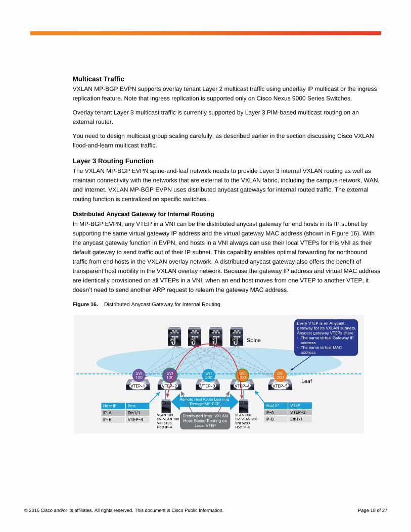
Distributed Anycast Gateway for Internal Routing
In MP-BGP EVPN, any VTEP in a VNI can be the distributed anycast gateway for end hosts in its IP subnet by
supporting the same virtual gateway IP address and the virtual gateway MAC address (shown in Figure 16). With
the anycast gateway function in EVPN, end hosts in a VNI always can use their local VTEPs for this VNI as their
default gateway to send traffic out of their IP subnet. This capability enables optimal forwarding for northbound
traffic from end hosts in the VXLAN overlay network. A distributed anycast gateway also offers the benefit of
transparent host mobility in the VXLAN overlay network. Because the gateway IP address and virtual MAC address
are identically provisioned on all VTEPs in a VNI, when an end host moves from one VTEP to another VTEP, it
doesn’t need to send another ARP request to relearn the gateway MAC address.
Figure 16. Distributed Anycast Gateway for Internal Routing
© 2016 Cisco and/or its affiliates. All rights reserved. This document is Cisco Public Information. Page 19 of 27
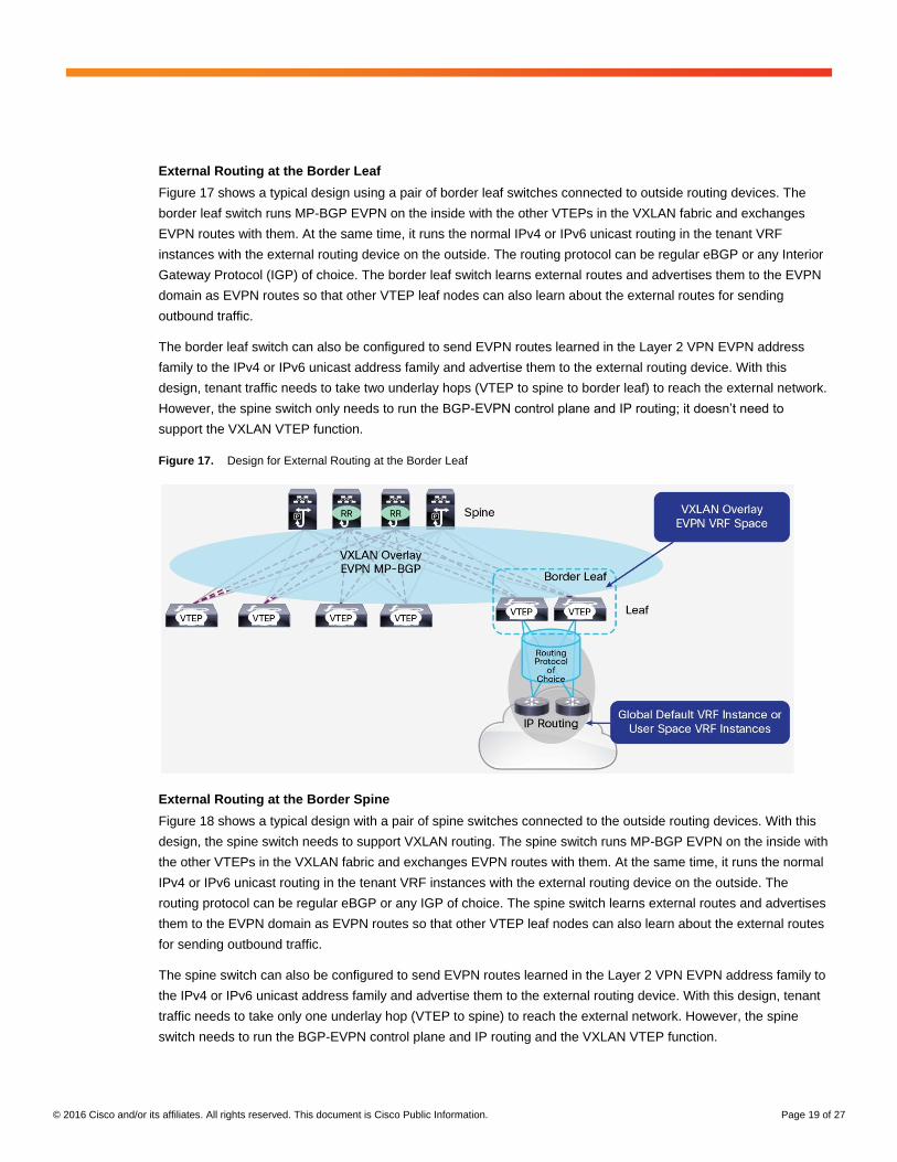
External Routing at the Border Leaf
Figure 17 shows a typical design using a pair of border leaf switches connected to outside routing devices. The
border leaf switch runs MP-BGP EVPN on the inside with the other VTEPs in the VXLAN fabric and exchanges
EVPN routes with them. At the same time, it runs the normal IPv4 or IPv6 unicast routing in the tenant VRF
instances with the external routing device on the outside. The routing protocol can be regular eBGP or any Interior
Gateway Protocol (IGP) of choice. The border leaf switch learns external routes and advertises them to the EVPN
domain as EVPN routes so that other VTEP leaf nodes can also learn about the external routes for sending
outbound traffic.
The border leaf switch can also be configured to send EVPN routes learned in the Layer 2 VPN EVPN address
family to the IPv4 or IPv6 unicast address family and advertise them to the external routing device. With this
design, tenant traffic needs to take two underlay hops (VTEP to spine to border leaf) to reach the external network.
However, the spine switch only needs to run the BGP-EVPN control plane and IP routing; it doesn’t need to
support the VXLAN VTEP function.
Figure 17. Design for External Routing at the Border Leaf
External Routing at the Border Spine
Figure 18 shows a typical design with a pair of spine switches connected to the outside routing devices. With this
design, the spine switch needs to support VXLAN routing. The spine switch runs MP-BGP EVPN on the inside with
the other VTEPs in the VXLAN fabric and exchanges EVPN routes with them. At the same time, it runs the normal
IPv4 or IPv6 unicast routing in the tenant VRF instances with the external routing device on the outside. The
routing protocol can be regular eBGP or any IGP of choice. The spine switch learns external routes and advertises
them to the EVPN domain as EVPN routes so that other VTEP leaf nodes can also learn about the external routes
for sending outbound traffic.
The spine switch can also be configured to send EVPN routes learned in the Layer 2 VPN EVPN address family to
the IPv4 or IPv6 unicast address family and advertise them to the external routing device. With this design, tenant
traffic needs to take only one underlay hop (VTEP to spine) to reach the external network. However, the spine
switch needs to run the BGP-EVPN control plane and IP routing and the VXLAN VTEP function.

© 2016 Cisco and/or its affiliates. All rights reserved. This document is Cisco Public Information. Page 20 of 27
Figure 18. External Routing with Border Spine Design
Multitenancy
The VXLAN MP-BGP EVPN spine-and-leaf architecture uses MP-BGP EVPN for the control plane. As an
extension to MP-BGP, MP-BGP EVPN inherits the support for multitenancy with VPN using the VRF construct. In
MP-BGP EVPN, multiple tenants can co-exist and share a common IP transport network while having their own
separate VPNs in the VXLAN overlay network (Figure 19).
In the VXLAN MP-BGP EVPN spine-and-leaf network, VNIs define the Layer 2 domains and enforce Layer 2
segmentation by not allowing Layer 2 traffic to traverse VNI boundaries. Similarly, Layer 3 segmentation among
VXLAN tenants is achieved by applying Layer 3 VRF technology and enforcing routing isolation among tenants by
using a separate Layer 3 VNI mapped to each VRF instance. Each tenant has its own VRF routing instance. IP
subnets of the VNIs for a given tenant are in the same Layer 3 VRF instance that separates the Layer 3 routing
domain from the other tenants.
Figure 19. Cisco VXLAN MP-BGP EVPN Spine-and-Leaf Network Multitenancy

© 2016 Cisco and/or its affiliates. All rights reserved. This document is Cisco Public Information. Page 21 of 27
Cisco VXLAN MP BGP-EVPN Spine-and-Leaf Network Summary
The VXLAN MP-BGP EVPN spine-and-leaf architecture uses MP-BGP EVPN for the control plane for VXLAN. This
design complies with IETF VXLAN standards RFC 7348 and draft-ietf-bess-evpn-overlay. It provides control-plane
and data-plane separation and a unified control plane for both Layer 2 and Layer 3 forwarding in a VXLAN overlay
network. The control-plane learns end-host Layer 2 and Layer 3 reachability information (MAC and IP addresses)
and distributes this information through the EVPN address family, thus providing integrated bridging and routing in
VXLAN overlay networks. It reduces network flooding through control-plane-based host MAC and IP address route
distribution and ARP suppression on the local VTEPs. The Layer 3 internal routed traffic is routed directly by a
distributed anycast gateway on each ToR switch in a scale-out fashion.
Table 3 summarizes the characteristics of the VXLAN MP-BGP EVPN spine-and-leaf network.
Table 3. Cisco VXLAN MP-BGP EVPN Network Characteristics
Item Description
Transport medium requirement Layer 3
Encapsulation VXLAN (MAC-in-IP packet encapsulation)
Unique node identifier VTEP
End-host detection Localized flood and learn with ARP suppression
Silent host discovery Yes
End-host reachability and distribution MP-BGP EVPN
Broadcast and unknown unicast traffic Forwarded by underlay multicast (PIM) or ingress replication
(Note: Ingress replication is supported only on Cisco Nexus 9000 Series Switches.)
Underlay control plane Any unicast routing protocol (static, OSPF, IS-IS, eBGP, etc.)
Overlay control plane MP-BGP EVPN
Layer 3 VXLAN gateway ● Distributed anycast gateway on leaf ToR switch for inter-VXLAN routing
● Border leaf switch for external routing
(Note: The spine switch only needs to run BGP-EVPN control plane and IP routing.)
● Border spine switch for external routing
(Note: The spine switch needs to support VXLAN routing VTEP on hardware.)
Layer 2 VXLAN gateway Leaf ToR switch
Multicast traffic Supports:
● Layer 2 multicast traffic (forwarded by underlay PIM or ingress replication)
(Note: Ingress replication is supported only on Cisco Nexus 9000 Series Switches.)
● Layer 3 IP multicast traffic (forwarded by Layer 3 PIM-based multicast routing on external router)
Multitenancy Supports both Layer 2 multitenancy and Layer 3 multitenancy
Standard reference RFC 7348 and draft-ietf-bess-evpn-overlay
Supported hardware ● Cisco Nexus 7000 Series Switches including the Cisco Nexus 7700 platform switches
● Cisco Nexus 5600 platform switches
● Cisco Nexus 9000 Series Switches
For feature support and more information about VXLAN MP-BGP EVPN, please refer to the configuration guides,
release notes, and reference documents listed at the end of this document.

© 2016 Cisco and/or its affiliates. All rights reserved. This document is Cisco Public Information. Page 22 of 27
Cisco MSDC Layer 3 Spine-and-Leaf Network
Massively scalable data centers (MSDCs) are large data centers, with at least a physical thousand servers
(sometimes hundreds of thousands), that have been designed to scale in size and computing capacity with little
impact on the existing infrastructure. Environments of this scale have a unique set of network requirements, with an
emphasis on operational simplicity and network stability. Examples of MSDCs are large cloud service providers
that host thousands of tenants, and web portal and e-commerce providers that host large distributed applications.
Cisco’s MSDC topology design uses a Layer 3 spine-and-leaf architecture. The leaf Layer is responsible for
advertising server subnets in the network fabric. Spine devices are responsible for learning infrastructure routes
and end-host subnet routes. In most cases, the spine switch is not used to directly connect to the outside world or
to other MSDC networks, but it will forward such traffic to specialized leaf switches acting as border leaf switches.
Border leaf switches can inject default routes to attract traffic intended for external destinations. In some cases,
multiple spine switches are connected together through dedicated super-spine switches. The Cisco MSDC control
plane uses dynamic Layer 3 protocols such as eBGP to build the routing table that most efficiently routes a packet
from a source to a spine node. Most customers use eBGP because of its scalability and stability.
Figure 20 shows an example of a Layer 3 MSDC spine-and-leaf network with an eBGP control plane
(AS = autonomous system).
Figure 20. Example of MSDC Layer 3 Spine-and-Leaf Network with BGP Control Plane
The Layer 3 spine-and-leaf design intentionally does not support Layer 2 VLANs across ToR switches because it is
a Layer 3 fabric. Each host is associated with a host subnet and talks with other hosts through Layer 3 routing.
Host mobility and multitenancy is not supported.
Because the fabric network is so large, MSDC customers typically use software-based approaches to introduce
more automation and more modularity into the network. The automation tools can handle different fabric topologies
and form factors, creating a modular solution that can adapt to different-sized data centers. MSDCs are highly
automated to deploy configurations on the devices and discover any new devices’ roles in the fabric, to monitor
and troubleshoot the fabric, etc. Many MSDC customers write scripts to make network changes, using Python,
Puppet and Chef, and other DevOps tools and Cisco technologies such as power-on autoprovisioning (POAP).
© 2016 Cisco and/or its affiliates. All rights reserved. This document is Cisco Public Information. Page 23 of 27
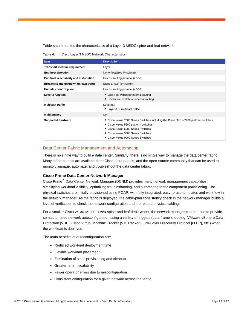
Table 4 summarizes the characteristics of a Layer 3 MSDC spine-and-leaf network.
Table 4. Cisco Layer 3 MSDC Network Characteristics
Item Description
Transport medium requirement Layer 3
End-host detection None (localized IP subnet)
End-host reachability and distribution Unicast routing protocol (eBGP)
Broadcast and unknown unicast traffic Stops at leaf ToR switch
Underlay control plane Unicast routing protocol (eBGP)
Layer 3 function ● Leaf ToR switch for internal routing
● Border leaf switch for external routing
Multicast traffic Supports:
● Layer 3 IP multicast traffic
Multitenancy No
Supported hardware ● Cisco Nexus 7000 Series Switches including the Cisco Nexus 7700 platform switches
● Cisco Nexus 5600 platform switches
● Cisco Nexus 6000 Series Switches
● Cisco Nexus 3000 Series Switches
● Cisco Nexus 9000 Series Switches
Data Center Fabric Management and Automation
There is no single way to build a data center. Similarly, there is no single way to manage the data center fabric.
Many different tools are available from Cisco, third parties, and the open-source community that can be used to
monitor, manage, automate, and troubleshoot the data center fabric.
Cisco Prime Data Center Network Manager
Cisco Prime™
Data Center Network Manager (DCNM) provides many network management capabilities,
simplifying workload visibility, optimizing troubleshooting, and automating fabric component provisioning. The
physical switches are initially provisioned using POAP, with fully integrated, easy-to-use templates and workflow in
the network manager. As the fabric is deployed, the cable-plan consistency check in the network manager builds a
level of verification to check the network configuration and the related physical cabling.
For a smaller Cisco VXLAN MP-BGP EVPN spine-and-leaf deployment, the network manager can be used to provide
semiautomated network autoconfiguration using a variety of triggers (data-frame snooping, VMware vSphere Data
Protection [VDP], Cisco Virtual Machine Tracker [VM Tracker], Link-Layer Discovery Protocol [LLDP], etc.) when
the workload is deployed.
The main benefits of autoconfiguration are:
● Reduced workload deployment time
● Flexible workload placement
● Elimination of static provisioning and cleanup
● Greater tenant scalability
● Fewer operator errors due to misconfiguration
● Consistent configuration for a given network across the fabric
© 2016 Cisco and/or its affiliates. All rights reserved. This document is Cisco Public Information. Page 24 of 27
For more information about Cisco Prime DCNM, see http://www.cisco.com/c/en/us/products/cloud-systems-
management/prime-data-center-network-manager/index.html.
Cisco Virtual Topology System
The Cisco Virtual Topology System (VTS) is a standards-based, open, software overlay management and
provisioning system. It automates data center network fabric provisioning for virtual and physical infrastructure. The
system offers a comprehensive set of automation and programmability capabilities across the entire Cisco Nexus
switching portfolio to enhance the deployment of cloud-based services.
Virtual Topology System is designed to help service provider and enterprise operations teams manage and
automate the provisioning of their data center overlay networks. It is especially suitable for organizations seeking to
reduce data center complexity and enhance the agility of their multitenant cloud environments. For more
information, see http://www.cisco.com/c/en/us/products/cloud-systems-management/virtual-topology-
system/index.html.
Ignite
Ignite is an open-source tool for bootstrapping a network device. It supports Cisco Nexus switches using POAP
capabilities. Ignite supports bootstrapping with topology design, configuration design, image and configuration
storage for POAP, POAP request handling, and other capabilities. For more information, see
http://github.com/datacenter/ignite.
Conclusion
This document presented several spine-and-leaf architecture designs from Cisco, including the most important
technology components and design considerations for each architecture at the time of the writing of this document.
The Cisco FabricPath spine-and-leaf network is proprietary to Cisco, but it is a mature technology with wide
deployment. It is simple, flexible, and stable; it has good scalability and fast convergence characteristics; and it
supports multiple parallel paths at Layer 2. But a FabricPath network is a flood-and-learn-based Layer 2
technology. Its control plane protocol is FabricPath IS-IS, which is designed to determine FabricPath switch ID
reachability information. To learn end-host reachability information, FabricPath switches rely on initial data-plane
traffic flooding. As the number of hosts in a broadcast domain increases, the negative effects of flooding packets
become more pronounced. The Layer 3 routing function is laid on top of the Layer 2 network. Common Layer 3
designs use centralized routing: that is, the Layer 3 routing function is centralized on specific switches (spine
switches or border leaf switches). The FabricPath network supports up to four anycast gateways for internal VLAN
routing.
The Cisco VXLAN flood-and-learn spine-and-leaf network complies with the IETF VXLAN standards (RFC 7348). It
transports Layer 2 frames over the Layer 3 IP underlay network. But it is still a flood-and-learn-based Layer 2
technology. As the number of hosts in a broadcast domain increases, it suffers the same flooding challenges as the
FabricPath spine-and-leaf network. The Layer 3 routing function is laid on top of the Layer 2 network. Common
Layer 3 designs use centralized routing: that is, the Layer 3 routing function is centralized on specific switches
(spine switches or border leaf switches). The VXLAN flood-and-learn spine-and-leaf network supports up to two
active-active gateways with vPC for internal VXLAN routing.

© 2016 Cisco and/or its affiliates. All rights reserved. This document is Cisco Public Information. Page 25 of 27
The Cisco VXLAN MP-BGP EVPN spine-and-leaf architecture uses MP-BGP EVPN for the control plane for
VXLAN. It complies with IETF VXLAN standards RFC 7348 and draft-ietf-bess-evpn-overlay. It provides control-
plane and data-plane separation and a unified control plane for both Layer 2 and Layer 3 forwarding in a VXLAN
overlay network. The Layer 3 internal routed traffic is routed directly by the distributed anycast gateway on each
ToR switch in a scale-out fashion. The VXLAN MP-BGP EVPN spine-and-leaf architecture offers the following main
benefits:
● The MP-BGP EVPN protocol is based on industry standards, allowing multivendor interoperability.
● It enables control-plane learning of end-host Layer 2 and Layer 3 reachability information, enabling
organizations to build more robust and scalable VXLAN overlay networks.
● It uses the decade-old MP-BGP VPN technology to support scalable multitenant VXLAN overlay networks.
● The EVPN address family carries both Layer 2 and Layer 3 reachability information, thus providing
integrated bridging and routing in VXLAN overlay networks.
● It reduces network flooding through protocol-based host MAC address IP address route distribution and
ARP suppression on the local VTEPs.
● It provides optimal forwarding for east-west and north-south traffic and supports workload mobility with the
distributed anycast function on each ToR switch.
● It provides VTEP peer discovery and authentication, mitigating the risk from rogue VTEPs in the VXLAN
overlay network.
● It provides mechanisms for building active-active multihoming at Layer 2.
● Its underlay and overlay management tools provide many network management capabilities, simplifying
workload visibility, optimizing troubleshooting, automating fabric component provisioning, automating
overlay tenant network provisioning, etc.
Cisco VXLAN MP-BGP EVPN spine-and-leaf architecture is one of the latest innovations from Cisco. It is designed
to simplify, optimize, and automate the modern multitenancy data center fabric environment.
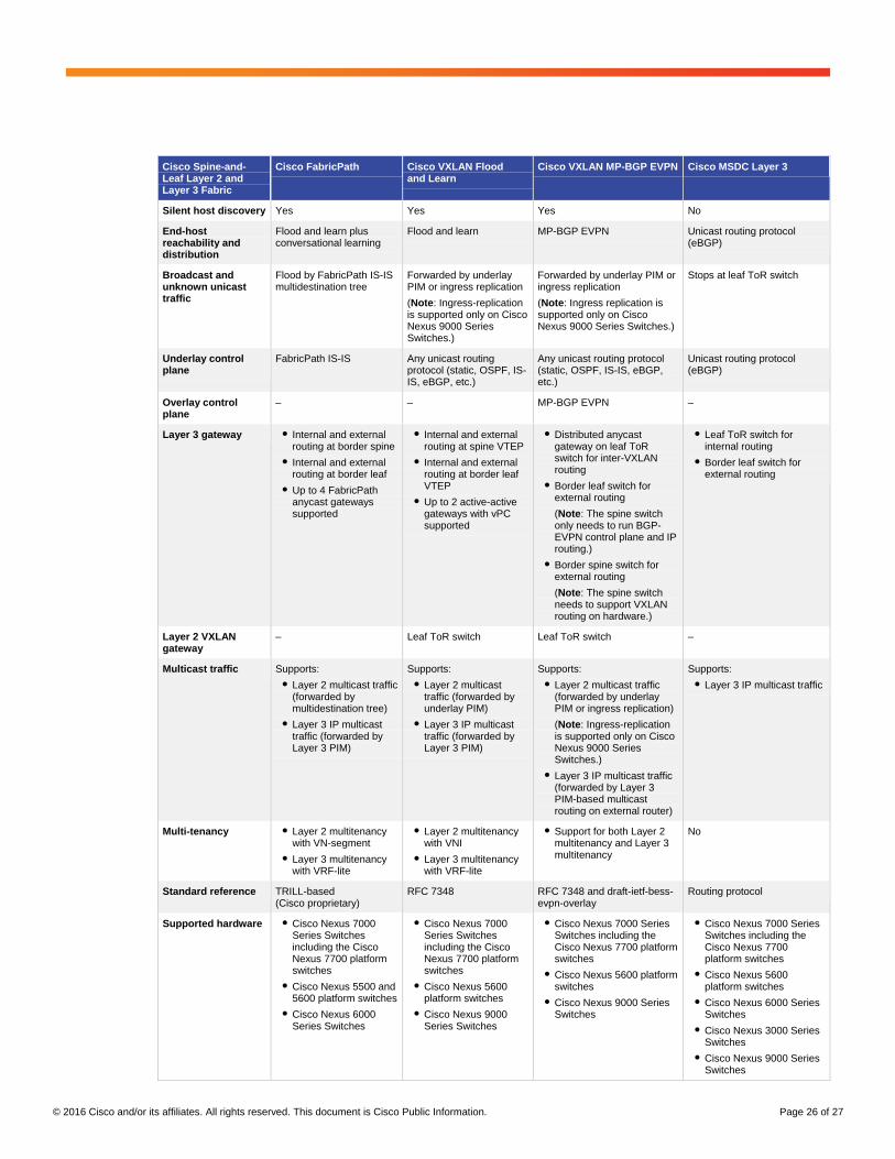
Cisco Spine-and-Leaf Layer 2 and Layer 3 Fabric Comparison
Table 5 compares the four Cisco spine-and-leaf architectures discussed in this document: FabricPath, VXLAN
flood-and-learn, VXLAN MP-BGP EVPN, and MSDC Layer 3 networks. Please review this table and each section
of this document carefully and read the reference documents to obtain additional information to help you choose
the technology that best fits your data center environment.
Table 5. Cisco Spine-and-Leaf Layer 2 and Layer 3 Fabric Comparison
Note: Accurate as of February 2016
Cisco Spine-and-Leaf Layer 2 and Layer 3 Fabric
Cisco FabricPath Cisco VXLAN Flood and Learn
Cisco VXLAN MP-BGP EVPN Cisco MSDC Layer 3
Transport medium requirement
Layer 1 Layer 3 Layer 3 Layer 3
Encapsulation FabricPath (MAC-in-MAC frame encapsulation)
VXLAN (MAC-in-IP packet encapsulation)
VXLAN (MAC-in-IP packet encapsulation)
–
Unique node identifier
FabricPath switch ID VTEP VTEP Layer 3 IP address or loopback address
End-host detection Flood and learn Flood and learn Localized flood and learn with ARP suppression
None (localized IP subnet)
© 2016 Cisco and/or its affiliates. All rights reserved. This document is Cisco Public Information. Page 26 of 27
Cisco Spine-and-Leaf Layer 2 and Layer 3 Fabric
Cisco FabricPath Cisco VXLAN Flood and Learn
Cisco VXLAN MP-BGP EVPN Cisco MSDC Layer 3
Silent host discovery Yes Yes Yes No
End-host reachability and distribution
Flood and learn plus conversational learning
Flood and learn MP-BGP EVPN Unicast routing protocol (eBGP)
Broadcast and unknown unicast traffic
Flood by FabricPath IS-IS multidestination tree
Forwarded by underlay PIM or ingress replication
(Note: Ingress-replication is supported only on Cisco Nexus 9000 Series Switches.)
Forwarded by underlay PIM or ingress replication
(Note: Ingress replication is supported only on Cisco Nexus 9000 Series Switches.)
Stops at leaf ToR switch
Underlay control plane
FabricPath IS-IS Any unicast routing protocol (static, OSPF, IS-IS, eBGP, etc.)
Any unicast routing protocol (static, OSPF, IS-IS, eBGP, etc.)
Unicast routing protocol (eBGP)
Overlay control plane
– – MP-BGP EVPN –
Layer 3 gateway ● Internal and external routing at border spine
● Internal and external routing at border leaf
● Up to 4 FabricPath anycast gateways supported
● Internal and external routing at spine VTEP
● Internal and external routing at border leaf VTEP
● Up to 2 active-active gateways with vPC supported
● Distributed anycast gateway on leaf ToR switch for inter-VXLAN routing
● Border leaf switch for external routing
(Note: The spine switch only needs to run BGP-EVPN control plane and IP routing.)
● Border spine switch for external routing
(Note: The spine switch needs to support VXLAN routing on hardware.)
● Leaf ToR switch for internal routing
● Border leaf switch for external routing
Layer 2 VXLAN gateway
– Leaf ToR switch Leaf ToR switch –
Multicast traffic Supports:
● Layer 2 multicast traffic (forwarded by multidestination tree)
● Layer 3 IP multicast traffic (forwarded by Layer 3 PIM)
Supports:
● Layer 2 multicast traffic (forwarded by underlay PIM)
● Layer 3 IP multicast traffic (forwarded by Layer 3 PIM)
Supports:
● Layer 2 multicast traffic (forwarded by underlay PIM or ingress replication)
(Note: Ingress-replication is supported only on Cisco Nexus 9000 Series Switches.)
● Layer 3 IP multicast traffic (forwarded by Layer 3 PIM-based multicast routing on external router)
Supports:
● Layer 3 IP multicast traffic
Multi-tenancy ● Layer 2 multitenancy with VN-segment
● Layer 3 multitenancy with VRF-lite
● Layer 2 multitenancy with VNI
● Layer 3 multitenancy with VRF-lite
● Support for both Layer 2 multitenancy and Layer 3 multitenancy
No
Standard reference TRILL-based (Cisco proprietary)
RFC 7348 RFC 7348 and draft-ietf-bess-evpn-overlay
Routing protocol
Supported hardware ● Cisco Nexus 7000 Series Switches including the Cisco Nexus 7700 platform switches
● Cisco Nexus 5500 and 5600 platform switches
● Cisco Nexus 6000 Series Switches
● Cisco Nexus 7000 Series Switches including the Cisco Nexus 7700 platform switches
● Cisco Nexus 5600 platform switches
● Cisco Nexus 9000 Series Switches
● Cisco Nexus 7000 Series Switches including the Cisco Nexus 7700 platform switches
● Cisco Nexus 5600 platform switches
● Cisco Nexus 9000 Series Switches
● Cisco Nexus 7000 Series Switches including the Cisco Nexus 7700 platform switches
● Cisco Nexus 5600 platform switches
● Cisco Nexus 6000 Series Switches
● Cisco Nexus 3000 Series Switches
● Cisco Nexus 9000 Series Switches

© 2016 Cisco and/or its affiliates. All rights reserved. This document is Cisco Public Information. Page 27 of 27
For More Information
For additional information, see the following references:
● Data center overlay technologies: http://www.cisco.com/c/en/us/products/collateral/switches/nexus-9000-
series-switches/white-paper-c11-730116.html
● VXLAN network with MP-BGP EVPN control plane:
http://www.cisco.com/c/en/us/products/collateral/switches/nexus-9000-series-switches/guide-c07-
734107.html
● VXLAN best practices: http://www.cisco.com/c/en/us/products/collateral/switches/nexus-5000-series-
switches/white-paper-c11-733618.html
● Cisco Virtual Topology System: Data Center Automation for Next-Generation Cloud Architectures white
paper: http://www.cisco.com/c/en/us/products/collateral/cloud-systems-management/virtual-topology-
system/white-paper-c11-734904.html
● Cisco Massively Scalable Data Center:
http://www.cisco.com/c/dam/en/us/td/docs/solutions/Enterprise/Data_Center/MSDC/1-0/MSDC_AAG_1.pdf
Printed in USA C11-737022-00 04/16


![Integración avanzada de Cisco ACI...Cisco ACI Kit [Leaf & Spine Fabric + APIC] APIC vSphere LAN Logicalis Spine: Nexus C9336PQ Leaf: Nexus C9372PX Extensión 13 OSPF 10 Area (NSSA)](https://static.documents.pub/doc/80x56/613b9313f8f21c0c826912af/integracin-avanzada-de-cisco-aci-cisco-aci-kit-leaf-spine-fabric-.jpg)