Americas Headquarters: Cisco Systems, Inc., 170 West Tasman Drive, San Jose, CA 95134-1706 USA Cisco Smart+Connected Video Door Station Reference Guide This document provides information and installation instructions for the Cisco Smart+Connected Video Door Station, which includes the following options: • Cisco Smart+Connected Video Door Station Internal (SCH-VDS-I) • Cisco Smart+Connected Video Door Station External (SCH-VDS-E) • Cisco Smart+Connected Video Door Station Back Box (SCH-VDS-BB) Contents Refer to the following topics for more information: • Introduction, page 3 • Box Contents, page 4 • Accessories, page 4 • Front Panel Description, page 5 • Prerequisites and Requirements, page 6 – Prerequisites, page 6 – Understanding the Power and Network Connection Options, page 7 – Grounding Requirements, page 9 – Mounting Tips, page 9 – Backlit Button Indicator, page 9 • Installing the Back Box, page 11 – Back Box Requirements, page 12 – Back Box Network and Power Considerations, page 12 – Back Box Mechanical Drawing, page 13 – Installing the Back Box, page 14
Transcript
Cisco Smart+Connected Video Door Station Reference Guide
This document provides information and installation instructions for the Cisco Smart+Connected Video Door Station, which includes the following options:
• Cisco Smart+Connected Video Door Station Internal (SCH-VDS-I)
• Cisco Smart+Connected Video Door Station External (SCH-VDS-E)
• Cisco Smart+Connected Video Door Station Back Box (SCH-VDS-BB)
ContentsRefer to the following topics for more information:
• Introduction, page 3
• Box Contents, page 4
• Accessories, page 4
• Front Panel Description, page 5
• Prerequisites and Requirements, page 6
– Prerequisites, page 6
– Understanding the Power and Network Connection Options, page 7
– Grounding Requirements, page 9
– Mounting Tips, page 9
– Backlit Button Indicator, page 9
• Installing the Back Box, page 11
– Back Box Requirements, page 12
– Back Box Network and Power Considerations, page 12
– Back Box Mechanical Drawing, page 13
– Installing the Back Box, page 14
Americas Headquarters:Cisco Systems, Inc., 170 West Tasman Drive, San Jose, CA 95134-1706 USA
Contents
• Installing the Cisco Video Door Station, page 18
– Inside Panel Description, page 18
– Connecting the Power and Network Cables, page 19
– Attach the Cisco Video Door Station, page 26
– Configure the Cisco Video Door Station, page 27
– Reset/Factory Restore the Cisco Video Door Station, page 27
– Installing the Wi-Fi Antennas, page 27
– Contact and Relay Connections, page 32
• Troubleshooting, page 34
– Boot Up, page 34
– Factory Restore, page 34
• Security Best Practices, page 34
• Specifications, page 36
• Regulatory/Safety Information, page 37
• Related Documentation, page 38
• Warranty, page 39
• Service and Support, page 39
2Cisco Smart+Connected Video Door Station Reference Guide
OL-27367-01
Introduction
IntroductionThe Cisco Smart+Connected Video Door Station provides easy-to-use, secure communications between a visitor at the door and the resident inside a dwelling. When a guest pushes the built-in doorbell, the resident hears an alert and is shown video of the guest on a Cisco In-wall Display or Cisco Portable Tablet. The resident can talk to the guest over the intercom and open the door with the press of a button.
The Cisco Video Door Station is available in two options designed for either internal or external use. There are also optional Wi-Fi antennas available in two lengths.
• The Internal Video Door Station is ideal for mounting within a protected building to view visitors before allowing them into the residence.
• The External Video Door Station is perfect for use outside a building or at a gated entrance where weather conditions vary.
Both Cisco Video Door Stations deliver full-motion video and the fidelity of wideband audio intercom for secure, crystal-clear communications throughout the residence.
Figure 1 Cisco Video Door Station: Internal (SCH-VDS-I) and External (SCH-VDS-E)
3Cisco Smart+Connected Video Door Station Reference Guide
OL-27367-01
Box Contents
Box ContentsCarefully unpack the Video Door Station from the box and ensure that the following items are included in the box. Contact your Cisco representative immediately if any parts are missing or if any component is damaged.
AccessoriesThe following accessories are sold separately. The Back Box is used to mount the unit in the wall. The antennas provide Wi-Fi communication if a wired Ethernet connection is not available.
Table 1 Box Contents
Cisco External Video Door Station(model SCH-VDS-E)
Cisco Internal Video Door Station(model SCH-VDS-I)
• Two (2) mounting screws
• Security screw tool
• Mounting screws, security head (5)
• Security screw tool
• Plate attachment screw (1)
• Plastic faceplate (1)
Table 2 Accessories
Accessory Part Number More Information
Back Box SCH-VDS-BB Installing the Back Box, page 11
4Cisco Smart+Connected Video Door Station Reference Guide
OL-27367-01
Front Panel Description
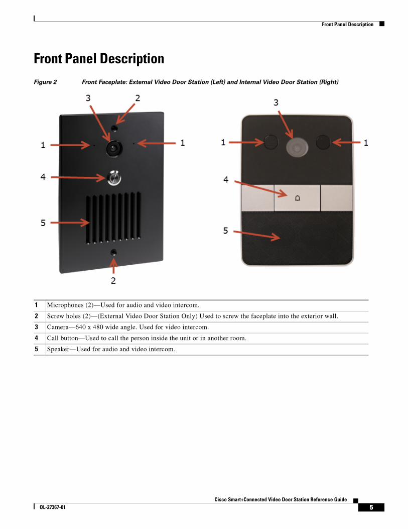
Front Panel DescriptionFigure 2 Front Faceplate: External Video Door Station (Left) and Internal Video Door Station (Right)
1 Microphones (2)—Used for audio and video intercom.
2 Screw holes (2)—(External Video Door Station Only) Used to screw the faceplate into the exterior wall.
3 Camera—640 x 480 wide angle. Used for video intercom.
4 Call button—Used to call the person inside the unit or in another room.
5 Speaker—Used for audio and video intercom.
5Cisco Smart+Connected Video Door Station Reference Guide
OL-27367-01
Prerequisites and Requirements
Prerequisites and RequirementsBefore you begin, review the following topics to ensure the unit will be properly installed, powered and available on the network.
• Prerequisites, page 6
• Understanding the Power and Network Connection Options, page 7
• Grounding Requirements, page 9
• Backlit Button Indicator, page 9
• Mounting Tips, page 9
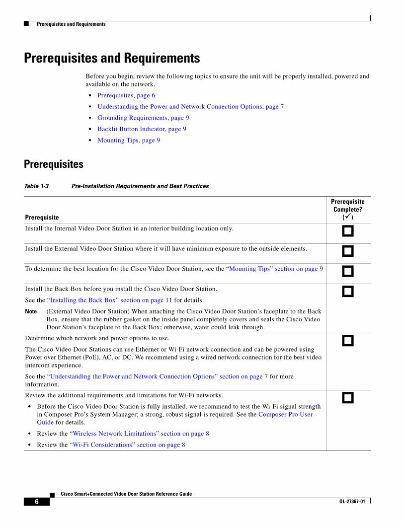
Prerequisites
Table 1-3 Pre-Installation Requirements and Best Practices
Prerequisite
Prerequisite Complete?
( )
Install the Internal Video Door Station in an interior building location only.
Install the External Video Door Station where it will have minimum exposure to the outside elements.
To determine the best location for the Cisco Video Door Station, see the “Mounting Tips” section on page 9
Install the Back Box before you install the Cisco Video Door Station.
See the “Installing the Back Box” section on page 11 for details.
Note (External Video Door Station) When attaching the Cisco Video Door Station’s faceplate to the Back Box, ensure that the rubber gasket on the inside panel completely covers and seals the Cisco Video Door Station’s faceplate to the Back Box; otherwise, water could leak through.
Determine which network and power options to use.
The Cisco Video Door Stations can use Ethernet or Wi-Fi network connection and can be powered using Power over Ethernet (PoE), AC, or DC. We recommend using a wired network connection for the best video intercom experience.
See the “Understanding the Power and Network Connection Options” section on page 7 for more information.
Review the additional requirements and limitations for Wi-Fi networks.
• Before the Cisco Video Door Station is fully installed, we recommend to test the Wi-Fi signal strength in Composer Pro’s System Manager; a strong, robust signal is required. See the Composer Pro User Guide for details.
• Review the “Wireless Network Limitations” section on page 8
• Review the “Wi-Fi Considerations” section on page 8
6Cisco Smart+Connected Video Door Station Reference Guide
Understanding the Power and Network Connection OptionsThe Cisco Video Door Stations can use Ethernet or Wi-Fi network connection and can be powered using Power over Ethernet (PoE), AC, or DC. We recommend using a wired network connection for the best video intercom experience.
Refer to the following topics for more information:
• Network Options, page 7
• Power Options, page 8
• Connecting the Power and Network Cables, page 19
Network Options
The Cisco Video Door Station can be connected using one of these network types:
• Standard Ethernet—(Recommended) Connect the Cisco Video Door Station to the RJ-45 LAN port using the RJ-45 Ethernet cable.
• Wi-Fi—The Wi-Fi antenna will communicate with the LAN’s WAP. If the LAN has a WAP set up, no additional wiring is needed except for power. See the “Installing the Wi-Fi Antennas” section on page 27 for details.
Note We recommend using an Ethernet connection rather than Wi-Fi for the best communication with the Cisco Smart+Connected Residential system.
Determine the grounding requirements for the Cisco Video Door Station.
See the “Grounding Requirements” section on page 9.
Note The grounding requirements are different for the internal and external units.
Use the contacts and relays for non-secure devices only. For example, don’t use it for a secured electronic gate. See the “Security Best Practices” section on page 34.
Determine whether you want a backlit button for the Cisco Video Door Station. The button’s backlight can be enabled or disabled in Composer Pro. You can also program the On/Off backlit button.
See the Composer Pro User Guide for details.
Before adding this device to a Composer Project
• Make sure the wireless access point (WAP) is on the same network as your Controller and that the signal is strong.
• Determine the other Cisco touchscreens that will be communicating with this Cisco Video Door Station.
Table 1-3 Pre-Installation Requirements and Best Practices (continued)
Prerequisite
Prerequisite Complete?
( )
7Cisco Smart+Connected Video Door Station Reference Guide
Many Wi-Fi Access Points handle Multicasts (Wi-Fi simultaneously sent to multiple devices, for example, when the Cisco Video Door Station broadcasts video to all stations) by slowing down transmission speed to the 1 Mb basic rate. This can cause overall Wi-Fi congestion in the Wi-Fi network during the broadcast. Video intercom response times and images may degrade at each device.
If a residence requires a large number of Wi-Fi video intercom devices, ensure that you have a robust Wi-Fi network (possibly consisting of multiple access points).
Wi-Fi Considerations
• Wi-Fi requires an antenna (sold separately). See the “Accessories” section on page 4.
• Ensure that the antenna’s tip does not touch the Cisco Video Door Station’s Back Box metal when threaded through the Back Box hole or any other metal surfaces. See the “Installing the Wi-Fi Antennas” section on page 27.
• Check the signal strength after you wire the Video Door Station but before securing the device in the wall. You can do that at the driver’s Properties page in Composer Pro. See the Composer Pro User Guide for details.
• Wireless-N is recommended for video intercom. See the “Wireless Network Limitations” section on page 8. Although this device supports b/g/n, 802.11 b is not recommended or supported for video intercom.
Power Options
Caution Do not attempt to use PoE, AC, and DC power at the same time. Choose only one power option.
The Cisco Video Door Station can be powered using one of the following options:
• Power over Ethernet (PoE)—The Ethernet network connection for the Cisco Video Door Station is provided through the PoE Injector. No additional wiring is needed.
• AC or DC—Used to power the Cisco Video Door Station when using an Ethernet (not PoE) or Wi-Fi network connection.
Note Ethernet cable. Install the ferrite clamp on the Ethernet cable inside the Back Box.
8Cisco Smart+Connected Video Door Station Reference Guide
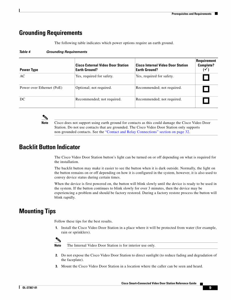
Grounding RequirementsThe following table indicates which power options require an earth ground.
Note Cisco does not support using earth ground for contacts as this could damage the Cisco Video Door Station. Do not use contacts that are grounded. The Cisco Video Door Station only supports non-grounded contacts. See the “Contact and Relay Connections” section on page 32.
Backlit Button IndicatorThe Cisco Video Door Station button’s light can be turned on or off depending on what is required for the installation.
The backlit button may make it easier to see the button when it is dark outside. Normally, the light on the button remains on or off depending on how it is configured in the system, however, it is also used to convey device status during certain times.
When the device is first powered on, the button will blink slowly until the device is ready to be used in the system. If the button continues to blink slowly for over 3 minutes, then the device may be experiencing a problem and should be factory restored. During a factory restore process the button will blink rapidly.
Mounting TipsFollow these tips for the best results.
1. Install the Cisco Video Door Station in a place where it will be protected from water (for example, rain or sprinklers).
Note The Internal Video Door Station is for interior use only.
2. Do not expose the Cisco Video Door Station to direct sunlight (to reduce fading and degradation of the faceplate).
3. Mount the Cisco Video Door Station in a location where the caller can be seen and heard.
Table 4 Grounding Requirements
Power Type Cisco External Video Door Station Earth Ground?
Cisco Internal Video Door Station Earth Ground?
Requirement Complete?
( )
AC Yes, required for safety. Yes, required for safety.
Power over Ethernet (PoE) Optional; not required. Recommended; not required.
DC Recommended; not required. Recommended; not required.
9Cisco Smart+Connected Video Door Station Reference Guide
OL-27367-01
Prerequisites and Requirements
• Mount the Video Door Station where the video camera is aimed at an average person’s height so the person inside the building gets a good view of the person calling in.
• Mount the Video Door Station so that the caller can comfortably speak into the microphone (about two (2) feet away or 60 cm).
• See the “Installing the Back Box” section on page 11 for more information.
4. We do not recommend using wireless (Wi-Fi) networking for a Video Door Station mounted outside your dwelling. If Wi-Fi is used, follow these guidelines:
• The wireless access protocol (WAP) broadcast to the installed location must be strong.
• Use Composer Pro’s System Manager to test the wireless signal after you’ve installed the Cisco Video Door Station, and then verify that the signal works correctly. See the Composer Pro User Guide for details.
10Cisco Smart+Connected Video Door Station Reference Guide
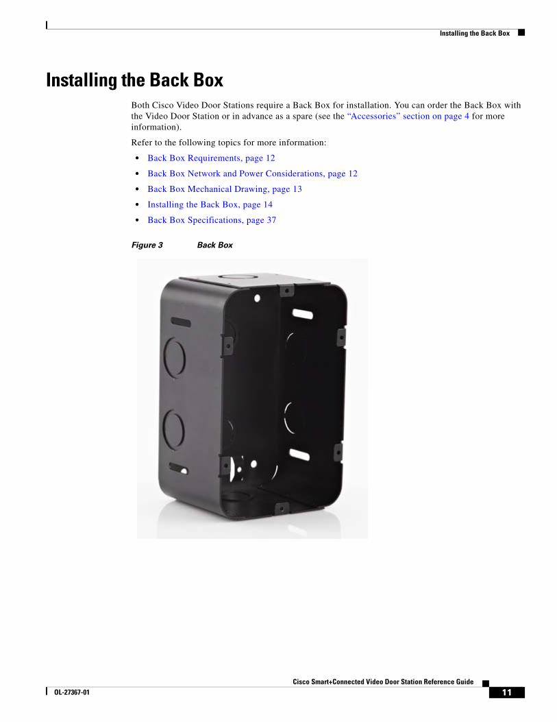
Installing the Back BoxBoth Cisco Video Door Stations require a Back Box for installation. You can order the Back Box with the Video Door Station or in advance as a spare (see the “Accessories” section on page 4 for more information).
Refer to the following topics for more information:
• Back Box Requirements, page 12
• Back Box Network and Power Considerations, page 12
• Back Box Mechanical Drawing, page 13
• Installing the Back Box, page 14
• Back Box Specifications, page 37
Figure 3 Back Box
11Cisco Smart+Connected Video Door Station Reference Guide
OL-27367-01
Installing the Back Box
Back Box Requirements
Back Box Network and Power Considerations This device uses an Ethernet or Wi-Fi network connection, and can be powered using PoE, AC, or DC.
Note We recommend using Ethernet rather than Wi-Fi for the best network connectivity. See “Understanding the Power and Network Connection Options” section on page 7 for wiring installation details.
Table 5 Back Box Requirements
Requirement
Requirement Complete?
( )
Mount the Back Box in an appropriate location. See the “Mounting Tips” section on page 9.
Tools to install the Back Box, such as a tape measure, pencil, hammer or screwdriver (depending on whether you are using screws or nails).
Nails or screws (4 to 6).
Antenna Kits (optional, sold separately). See the “Accessories” section on page 4 and the “Installing the Wi-Fi Antennas” section on page 27.
12Cisco Smart+Connected Video Door Station Reference Guide
OL-27367-01
Installing the Back Box
Back Box Mechanical DrawingThe following figure shows the dimensions of the metal black box. All tolerances are : ± 0.01 in (± 0.25 mm).
Figure 4 Back Box Mechanical Drawing
13Cisco Smart+Connected Video Door Station Reference Guide
OL-27367-01
Installing the Back Box
Installing the Back Box
Note • Place the Back Box between studs. Do not attempt to install a Back Box over a wall stud.
• If you are required to conform to NEMA safety standards, make sure you install a strain-relief cord (sold separately) in the punchout on the Back Box before inserting the wires. See the “Regulatory/Safety Information” section on page 37 or the NEMA website at: http://www.nema.org/stds/ for details.
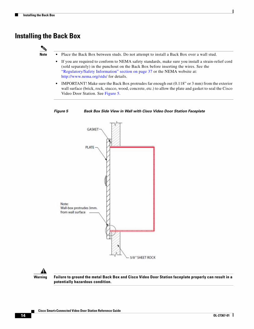
• IMPORTANT! Make sure the Back Box protrudes far enough out (0.118” or 3 mm) from the exterior wall surface (brick, rock, stucco, wood, concrete, etc.) to allow the plate and gasket to seal the Cisco Video Door Station. See Figure 5.
Figure 5 Back Box Side View in Wall with Cisco Video Door Station Faceplate
Warning Failure to ground the metal Back Box and Cisco Video Door Station faceplate properly can result in a potentially hazardous condition.
14Cisco Smart+Connected Video Door Station Reference Guide
Warning IMPORTANT! Improper use or installation can cause LOSS/DAMAGE OF PROPERTY.
Warning WARNING! Before you install the Cisco Video Door Station Back Box, switch off the circuit breaker or remove the fuse from the fuse box.
Procedure
Step 1 Feed either the AC, DC, or PoE wires through a tab in the back of the Back Box. See the “Installing the Cisco Video Door Station” section on page 18 to determine your installation option.
Step 2 After you’ve placed the Back Box inside the wall, tighten the screws or nails.
Step 3 Attach the ground wires to the Back Box and Cisco Video Door Station plate in the location indicated by the ground symbol (also, see Figure 6 and Figure 7).
There are two (2) ground screws in the Back Box: one (1) for earth ground and one (1) for grounding the Cisco Video Door Station faceplate to the Back Box.
Step 4 If you use Wi-Fi, the Wi-Fi antenna must be installed in the Back Box and extend outside the box.
Note Do not allow any contact of the antenna element to any metal surface on the Back Box; otherwise, antenna performance will diminish.
15Cisco Smart+Connected Video Door Station Reference Guide
OL-27367-01
Installing the Back Box
Figure 6 Ground Wire to Cisco Video Door Station
1 Ground wire
16Cisco Smart+Connected Video Door Station Reference Guide
OL-27367-01
Installing the Back Box
Figure 7 Ground Wires from Cisco Video Door Station to Back Box
1 Back box
2 Cisco Video Door Station faceplate
3 Ground wire
17Cisco Smart+Connected Video Door Station Reference Guide
OL-27367-01
Installing the Cisco Video Door Station
Installing the Cisco Video Door StationRefer to the following topics for information and instructions to install the Cisco Smart+Connected Video Door Station.
• Inside Panel Description, page 18
• Connecting the Power and Network Cables, page 19
• Attach the Cisco Video Door Station, page 26
• Configure the Cisco Video Door Station, page 27
• Reset/Factory Restore the Cisco Video Door Station, page 27
• Installing the Wi-Fi Antennas, page 27
• Contact and Relay Connections, page 32
Inside Panel Description
Figure 8 Inside Panel: External Video Door Station (Left) and Internal Video Door Station (Right)
1 AC connection—Used to connect the wires for AC power.
2 Contacts/Relays—Used to connect the wires for third-party devices.
Note Use the contacts and relays for nonsecure devices only. For example, don’t attach security gate wires to this terminal block.
18Cisco Smart+Connected Video Door Station Reference Guide
OL-27367-01
Installing the Cisco Video Door Station
Connecting the Power and Network CablesChoose one of the following options to connect the Cisco Video Door Station’s wiring:
Option 1 (Recommended): Ethernet Connection with a PoE Injector or Switch
In this option, electrical current is injected into the Ethernet cable by a PoE Injector. This method provides the Cisco Video Door Station with both power and a network connection.
Procedure
Step 1 Plug the Ethernet cable into the Cisco Video Door Station (Figure 9).
Step 2 (Optional) Connect an earth ground:
a. Connect a ground wire from the Video Door Station to one of the back box lugs.
b. Connect a second earth-ground or house-ground wire from the second back box lug to the home.
Note See the “Grounding Requirements” section on page 9 for more information.
3 Reset Button—Used to reset or factory restore the Cisco Video Door Station. Press the vertical bar to reset.
4 DC connection—Used to connect the wires for DC power.
5 Ethernet connection—Supports PoE.
Table 6 Power and Network Connection Options
Option More Information
Ethernet with PoE (recommended)
Option 1 (Recommended): Ethernet Connection with a PoE Injector or Switch, page 19
Ethernet with AC Option 2: Ethernet Connection with AC Power, page 20
Ethernet with DC Option 3: Ethernet Connection with DC Power, page 21
Wi-Fi with AC Option 4: Wi-Fi Connection with AC Power, page 22
Wi-Fi with DC Option 5: Wi-Fi Connection with DC Power, page 24
Wi-Fi with PoE Option 6: Wi-Fi Connection with PoE, page 25
19Cisco Smart+Connected Video Door Station Reference Guide
OL-27367-01
Installing the Cisco Video Door Station
Figure 9 Ethernet Connection: External Video Door Station (Left) and Internal Video Door Station (Right)
Option 2: Ethernet Connection with AC Power
Use this option to connect Ethernet networking and AC power.
Procedure
Step 1 Plug the Ethernet cable into the Cisco Video Door Station (Figure 10).
Step 2 Connect a ground wire from the Cisco Video Door Station to one of the Back Box lugs (see Figure 17).
Step 3 Connect a second earth-ground or house-ground wire from the second Back Box lug to the residence. See “Grounding Requirements” section on page 9 for details about earth grounding.
Step 4 Connect the neutral (N) (-) and hot (L) (+) wires to the AC power source for the Cisco Video Door Station according to the national and local electrical codes.
Tip The hot or ‘L’ (+) wire’s connector is closest to the bottom of the Cisco Video Door Station’s plate.
Step 5 Your installation may require alternative wires and the use of a terminal block. Strip the power wires to 1/4” on the end if necessary.
1 Ethernet connection
2 Ground wire.
Optional for the see the Internal Video Door Station only. See the “Grounding Requirements” section on page 9).
20Cisco Smart+Connected Video Door Station Reference Guide
OL-27367-01
Installing the Cisco Video Door Station
Figure 10 Ethernet with AC Power: External Video Door Station (Left) and Internal Video Door Station (Right)
Option 3: Ethernet Connection with DC Power
Use this option to connect Ethernet networking and DC power.
Procedure
Step 1 Plug the Ethernet cable into the Cisco Video Door Station (see Figure 11).
Step 2 Connect a ground wire from the Video Door Station to one of the Back Box lugs (see Figure 17).
Step 3 Connect a second earth-ground or house-ground wire from the second Back Box lug to the residence. See the “Grounding Requirements” section on page 9 for details about earth grounding.
Step 4 Connect the negative (-) and positive (+) wires to the DC power source for the Video Door Station according to the national and local electrical codes.
Tip The positive (+) wire’s connector is located on the bottom left side of the Video Door Station’s plate.
Step 5 Your installation may require alternative wires and the use of a terminal block (see Figure 11). Strip the power wires to 1/4” on the end if necessary.
1 Ethernet cable
2 AC connections (hot and load)
3 Ground wire
21Cisco Smart+Connected Video Door Station Reference Guide
OL-27367-01
Installing the Cisco Video Door Station
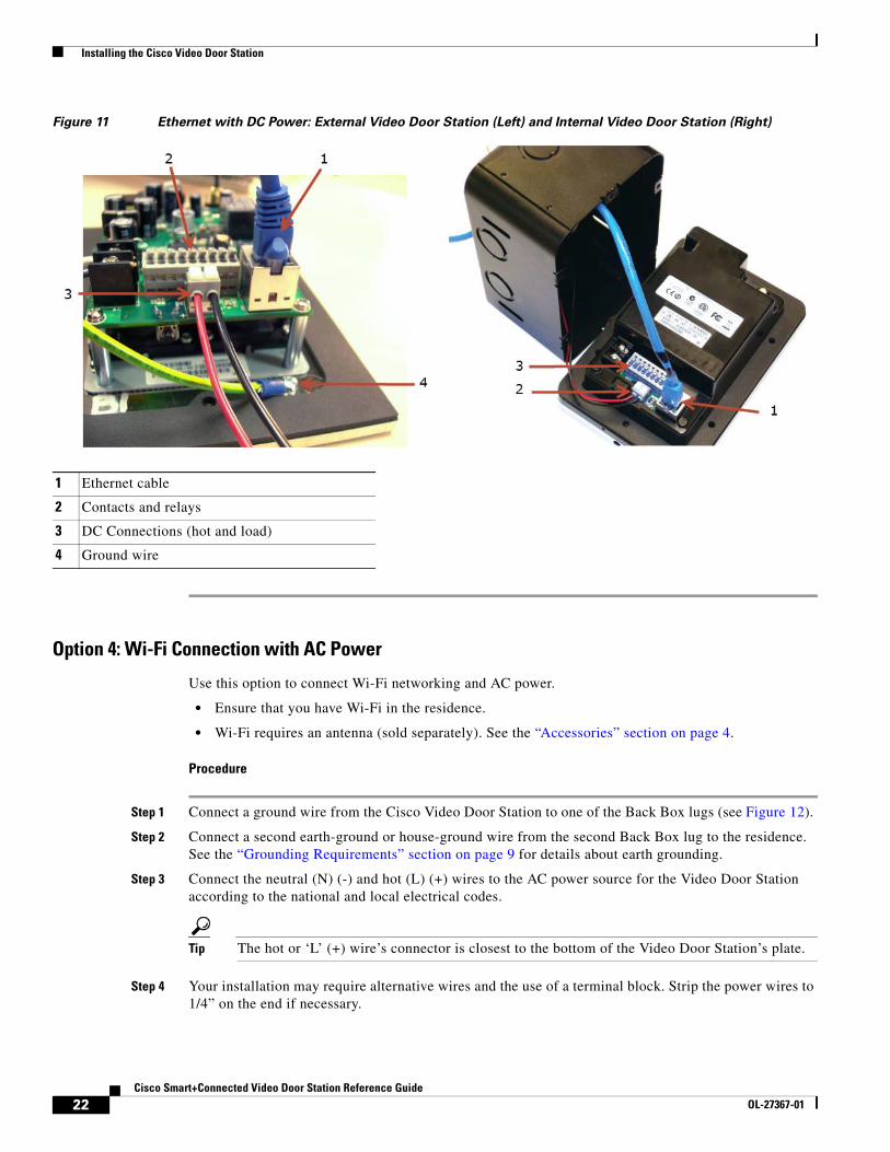
Figure 11 Ethernet with DC Power: External Video Door Station (Left) and Internal Video Door Station (Right)
Option 4: Wi-Fi Connection with AC Power
Use this option to connect Wi-Fi networking and AC power.
• Ensure that you have Wi-Fi in the residence.
• Wi-Fi requires an antenna (sold separately). See the “Accessories” section on page 4.
Procedure
Step 1 Connect a ground wire from the Cisco Video Door Station to one of the Back Box lugs (see Figure 12).
Step 2 Connect a second earth-ground or house-ground wire from the second Back Box lug to the residence. See the “Grounding Requirements” section on page 9 for details about earth grounding.
Step 3 Connect the neutral (N) (-) and hot (L) (+) wires to the AC power source for the Video Door Station according to the national and local electrical codes.
Tip The hot or ‘L’ (+) wire’s connector is closest to the bottom of the Video Door Station’s plate.
Step 4 Your installation may require alternative wires and the use of a terminal block. Strip the power wires to 1/4” on the end if necessary.
1 Ethernet cable
2 Contacts and relays
3 DC Connections (hot and load)
4 Ground wire
22Cisco Smart+Connected Video Door Station Reference Guide
OL-27367-01
Installing the Cisco Video Door Station
Step 5 Attach the antenna (3m or 26cm) to the Video Door Station. See the “Installing the Wi-Fi Antennas” section on page 27 for details.
Step 6 Run the antenna wire through the Back Box hole (see Figure 12). Ensure that the wire doesn’t touch the Back Box.
Step 7 Align the antenna vertically to the wall outside the Back Box (26cm antenna) or run the antenna through the wall (3m antenna). See the “Installing the Wi-Fi Antennas” section on page 27 for details.
Figure 12 Wi-Fi with AC Power: External Video Door Station (Left) and Internal Video Door Station (Right)
1 Antenna
2 Back box
3 AC connections (hot and load)
4 Ethernet (not used)
5 Ground wire
23Cisco Smart+Connected Video Door Station Reference Guide
OL-27367-01
Installing the Cisco Video Door Station
Option 5: Wi-Fi Connection with DC Power
Use this option to connect Wi-Fi networking and DC power.
• Ensure that you have Wi-Fi in the residence.
• Wi-Fi requires an antenna (sold separately). See the “Accessories” section on page 4.
Procedure
Step 1 Connect a ground wire from the Cisco Video Door Station to one of the Back Box lugs (see Figure 17).
Step 2 Connect a second earth-ground or house-ground wire from the second Back Box lug to the residence. See the “Grounding Requirements” section on page 9 for details about earth grounding.
Step 3 Connect the negative (-) and positive (+) wires to the DC power source for the Video Door Station according to the national and local electrical codes.
Note The positive (+) wire’s connector is located on the bottom left side of the Video Door Station’s plate.
Step 4 Your installation may require alternative wires and the use of a terminal block. Strip the power wires to 1/4” on the end if necessary.
Step 5 Attach the antenna (3m or 26cm) to the Cisco Video Door Station. See the “Installing the Wi-Fi Antennas” section on page 27 for details.
Step 6 Run the antenna wire through the Back Box hole (see Figure 17). Ensure that the wire doesn’t touch the Back Box.
Step 7 Align the antenna vertically to the wall outside the Back Box (26cm antenna) or run the antenna through the wall (3m antenna).
24Cisco Smart+Connected Video Door Station Reference Guide
OL-27367-01
Installing the Cisco Video Door Station
Figure 13 Wi-Fi with DC Power: External Video Door Station (Left) and Internal Video Door Station (Right)
Option 6: Wi-Fi Connection with PoE
Use this option for a Wi-Fi network and PoE power.
• Ensure that you have Wi-Fi in the residence.
• Wi-Fi requires an antenna (sold separately).
Procedure
Step 1 Plug the Ethernet cable into the Video Door Station (see Figure 14).
Step 2 (Optional) Connect the earth ground:
a. Connect a ground wire from the Video Door Station to one of the back box lugs.
b. Connect a second earth-ground or house-ground wire from the second back box lug to the home.
Note See the “Grounding Requirements” section on page 9 for more information.
1 Ethernet (not used)
2 Antenna
3 Contacts and relays
4 DC connections (hot and load)
5 Ground wire
25Cisco Smart+Connected Video Door Station Reference Guide
OL-27367-01
Installing the Cisco Video Door Station
Step 3 Attach the antenna (3m or 26cm) to the Video Door Station. See the “Installing the Wi-Fi Antennas” section on page 27 for details.
Step 4 Run the antenna wire through the Back Box hole (see Figure 17). Ensure that the wire doesn’t touch the Back Box.
Step 5 Align the antenna vertically to the wall outside the Back Box (26cm antenna) or run the antenna through the wall (3m antenna).
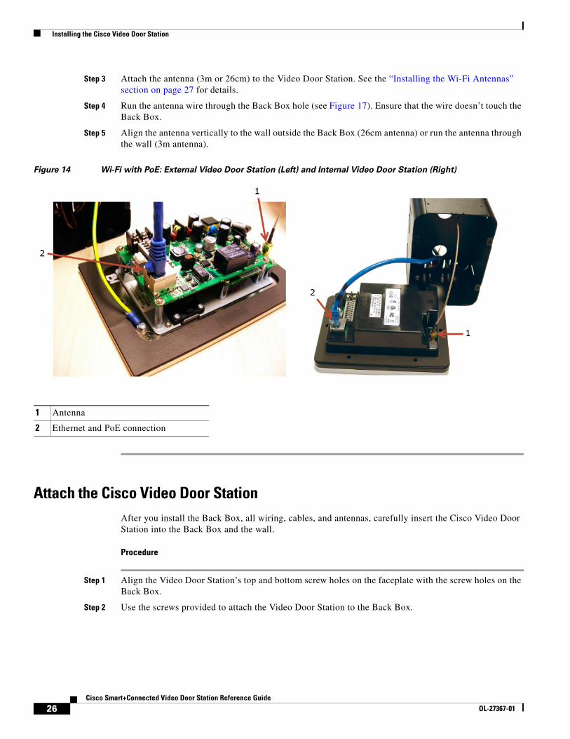
Figure 14 Wi-Fi with PoE: External Video Door Station (Left) and Internal Video Door Station (Right)
Attach the Cisco Video Door StationAfter you install the Back Box, all wiring, cables, and antennas, carefully insert the Cisco Video Door Station into the Back Box and the wall.
Procedure
Step 1 Align the Video Door Station’s top and bottom screw holes on the faceplate with the screw holes on the Back Box.
Step 2 Use the screws provided to attach the Video Door Station to the Back Box.
1 Antenna
2 Ethernet and PoE connection
26Cisco Smart+Connected Video Door Station Reference Guide
OL-27367-01
Installing the Cisco Video Door Station
Step 3 To prevent future moisture and dust from getting inside the Video Door Station, make sure the rubber gasket on the inside panel of the Video Door Station completely covers and seals the Video Door Station’s faceplate against the Back Box.
Configure the Cisco Video Door Station
Procedure
To configure the Video Door Station in Composer Pro:
Step 1 Open Composer Pro.
Step 2 Double-click the Video Door Station driver to add it to a room in the project.
Step 3 Identify the device to the project.
Note (Wi-Fi only) For your convenience, the Cisco Video Door Station driver includes a meter to check Wi-Fi signal strength. Use System Manager in Composer Pro to configure the Wi-Fi parameters. See the Composer Pro User Guide for details.
Reset/Factory Restore the Cisco Video Door Station
Procedure
To reset or factory restore the Video Door Station:
Step 1 Remove the faceplate and pull the Video Door Station out from the Back Box just enough to expose the Reset button (see Figure 8).
Step 2 While powered press the Reset button on the bottom of the Video Door Station to reset or restore the Cisco Video Door Station.
• Quick press—Press to reset the Video Door Station.
• Long press—Press until the button on the faceplate begins to blink rapidly. At that time, the factory restore starts. This action restores the Video Door Station to its factory default settings.
Step 3 When you are finished, insert the Video Door Station back into the Back Box and screw the faceplate back on.
Installing the Wi-Fi Antennas
Note We recommend installing the Cisco Video Door Station using wired Ethernet. Use the Wi-Fi option only if a wired Ethernet connection is not available.
27Cisco Smart+Connected Video Door Station Reference Guide
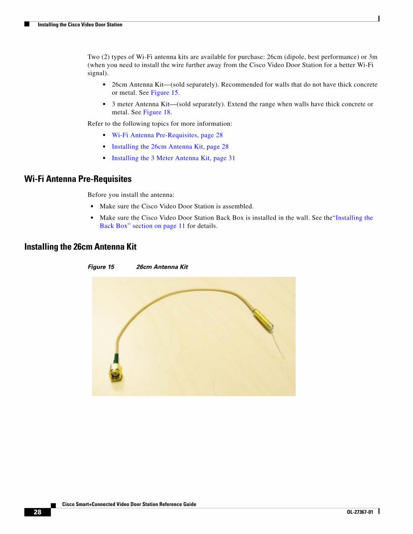
Two (2) types of Wi-Fi antenna kits are available for purchase: 26cm (dipole, best performance) or 3m (when you need to install the wire further away from the Cisco Video Door Station for a better Wi-Fi signal).
• 26cm Antenna Kit—(sold separately). Recommended for walls that do not have thick concrete or metal. See Figure 15.
• 3 meter Antenna Kit—(sold separately). Extend the range when walls have thick concrete or metal. See Figure 18.
Refer to the following topics for more information:
• Wi-Fi Antenna Pre-Requisites, page 28
• Installing the 26cm Antenna Kit, page 28
• Installing the 3 Meter Antenna Kit, page 31
Wi-Fi Antenna Pre-Requisites
Before you install the antenna:
• Make sure the Cisco Video Door Station is assembled.
• Make sure the Cisco Video Door Station Back Box is installed in the wall. See the“Installing the Back Box” section on page 11 for details.
Installing the 26cm Antenna Kit
Figure 15 26cm Antenna Kit
28Cisco Smart+Connected Video Door Station Reference Guide
OL-27367-01
Installing the Cisco Video Door Station
Procedure
Step 1 Remove the antenna from its packaging.
Step 2 Attach the antenna’s plug to the RSMA connector on the Cisco Video Door Station (see Figure 16).
Figure 16 Antenna to RSMA Connector: External Video Door Station (Left) and Internal Video Door Station (Right)
1 Antenna
2 RSMA connector
29Cisco Smart+Connected Video Door Station Reference Guide
OL-27367-01
Installing the Cisco Video Door Station
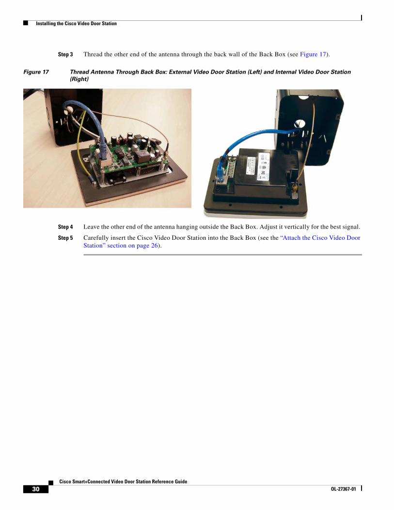
Step 3 Thread the other end of the antenna through the back wall of the Back Box (see Figure 17).
Figure 17 Thread Antenna Through Back Box: External Video Door Station (Left) and Internal Video Door Station
(Right)
Step 4 Leave the other end of the antenna hanging outside the Back Box. Adjust it vertically for the best signal.
Step 5 Carefully insert the Cisco Video Door Station into the Back Box (see the “Attach the Cisco Video Door Station” section on page 26).
30Cisco Smart+Connected Video Door Station Reference Guide
OL-27367-01
Installing the Cisco Video Door Station
Installing the 3 Meter Antenna Kit
Figure 18 3 Meter Antenna Kit
Procedure
Step 1 Attach the antenna’s plug to the RSMA connector on the Cisco Video Door Station (see Figure 16).
Step 2 Thread the other end of the antenna through the back wall of the Back Box and through the wall as needed (see Figure 17).
Step 3 Carefully insert the Cisco Video Door Station into the Back Box (see the “Attach the Cisco Video Door Station” section on page 26).
31Cisco Smart+Connected Video Door Station Reference Guide
OL-27367-01
Installing the Cisco Video Door Station
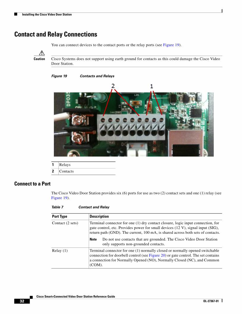
Contact and Relay ConnectionsYou can connect devices to the contact ports or the relay ports (see Figure 19).
Caution Cisco Systems does not support using earth ground for contacts as this could damage the Cisco Video Door Station.
Figure 19 Contacts and Relays
Connect to a Port
The Cisco Video Door Station provides six (6) ports for use as two (2) contact sets and one (1) relay (see Figure 19).
1 Relays
2 Contacts
Table 7 Contact and Relay
Port Type Description
Contact (2 sets) Terminal connector for one (1) dry contact closure, logic input connection, for gate control, etc. Provides power for small devices (12 V), signal input (SIG), return path (GND). The current, 100 mA, is shared across both sets of contacts.
Note Do not use contacts that are grounded. The Cisco Video Door Station only supports non-grounded contacts.
Relay (1) Terminal connector for one (1) normally closed or normally opened switchable connection for doorbell control (see Figure 20) or gate control. The set contains a connection for Normally Opened (NO), Normally Closed (NC), and Common (COM).
32Cisco Smart+Connected Video Door Station Reference Guide
OL-27367-01
Installing the Cisco Video Door Station
Figure 20 Contact/Relay Locations
Procedure
Step 1 To attach the wires to the contacts or relay, select one of the large bottom-row holes (see Figure 19; notice that the top row holes are smaller than the bottom-row holes).
Step 2 Using a small flat screwdriver, insert the screwdriver into the slot on the small block that sits between the two rows of holes adjacent to the port and push down firmly. The block will depress.
Step 3 Insert the wire. Ensure that the wire inserts all the way into the hole.
Step 4 Release the screwdriver.
Example Wiring
Figure 21 Relay Port: Normally Open (e.g., Doorbell)
33Cisco Smart+Connected Video Door Station Reference Guide
OL-27367-01
Troubleshooting
Troubleshooting
Boot UpWhen the Cisco Video Door Station is booting up, if the button blinks and does not stop after (3) minutes or longer, there is a problem with the device and it will have to be restored. See the “Reset/Factory Restore the Cisco Video Door Station” section on page 27.
Factory RestoreTo restore the device to its default factory settings. See the “Reset/Factory Restore the Cisco Video Door Station” section on page 27.
Security Best PracticesThe Video Door Station has connections for relays (to open doors, gates, etc.) and contacts. If installed without the proper security precautions, unauthorized access to the Video Door Station could provide access to Ethernet signals, signaling, and gate or door relays. We advise you to be aware of these risks and take all necessary precautions depending on each specific installation you will be doing.
It is each installer’s sole responsibility to advise their customer at each installation of any security risks specific to such installation. Cisco makes no claims, representations or warranties regarding the security of this product and accepts no liability for any security risk attendant to a specific installation.
1. The Cisco Video Door Station ships standard with security screws. Installers are encouraged to use these screws, or even substitute alternate security screws per the installer’s or customer’s preference. Screw size is metric M3.5x.6-30L.
2. Security gates or automatic doors should not be connected to the relay in the Cisco Video Door Station if mounted in an unsecured area; such relays could be accessed in the event of a breach of the device. Secure relay-driven devices should be connected to a more secure relay controller mounted behind a secure wall.
3. Security devices, for example numeric keypads, should not be connected to the contact sensors in the Cisco Video Door Station if mounted in an unsecured area; such devices could be accessed in the event of a breach of the device. Security-sensitive devices should be connected to more secure contacts mounted behind a secure wall.
4. Although the best video performance will be enabled by Ethernet connectivity, unauthorized access to the Cisco Video Door Station could provide access to the dwelling’s Ethernet network and corresponding personal data.
There are alternatives to mitigate this risk. The installer should consider the following options:
• Running the Cisco Smart+Connected Residential Solution on an isolated LAN from PCs on the network would limit exposure to personal data.
• Running MAC address filtering on the router or switch to force a hacker to spoof the Cisco Video Door Station’s MAC address to gain access to the LAN.
• Configuring the Cisco Video Door Station as Wi-Fi instead of Ethernet would allow the installer to use robust Wi-Fi security protocols, for example, WPA.
34Cisco Smart+Connected Video Door Station Reference Guide
OL-27367-01
Security Best Practices
Note Wi-Fi signals must be very strong and stable to support video intercom.
• Routing the Ethernet cable to the Cisco Video Door Station through a secure, managed switch to limit data access from the Cisco Video Door Station.
Installers should take time to assure they are not creating an unforeseen security risk for the customer, and any such risks should be discussed with the customer prior to the installation.
Carefully consider with your customer any contacts or relays before connecting them to the Cisco Video Door Station, and what implications could arise if someone gained access to the rear of the Cisco Video Door Station.
Also, think about what could happen if someone gained access to the Ethernet cable, and take necessary precautions to protect private customer information unless your customer is willing to assume these risks. Making available the proper security protections to a customer for their residence is the responsibility of the installer.
35Cisco Smart+Connected Video Door Station Reference Guide
OL-27367-01
Specifications
Specifications • Cisco Video Door Station Specifications, page 36
• Back Box Specifications, page 37
Cisco Video Door Station Specifications
Table 8 Cisco Video Door Station Specifications
Product Cisco Internal Video Door Station Cisco External Video Door Station
Service and Support Cisco offers a wide range of support programs to accelerate customer success. These innovative programs are delivered through a unique combination of people, processes, tools, and partners, resulting in high levels of customer satisfaction. For more information, contact your Cisco sales representative or go to www.cisco.com/cisco/web/support/index.html
This document is to be used in conjunction with the documents listed in the “Related Documentation” section.
Cisco and the Cisco logo are trademarks or registered trademarks of Cisco and/or its affiliates in the U.S. and other countries. To view a list of Cisco trademarks, go to this URL: www.cisco.com/go/trademarks. Third-party trademarks mentioned are the property of their respective owners. The use of the word partner does not imply a partnership relationship between Cisco and any other company. (1110R)
Any Internet Protocol (IP) addresses and phone numbers used in this document are not intended to be actual addresses and phone numbers. Any examples, command display output, network topology diagrams, and other figures included in the document are shown for illustrative purposes only. Any use of actual IP addresses or phone numbers in illustrative content is unintentional and coincidental.