39
Adopted May 3, 2016 2020 Update Adopted November 10, 2020 City of Fort Worth, Texas Master Thoroughfare Plan
Adopted May 3, 2016 2020 Update Adopted November 10, 2020
City of Fort Worth, Texas
Master Thoroughfare Plan
City of Fort Worth Master Thoroughfare Plan Adopted November 10, 2020 i
City of Fort Worth Hon. Mayor Betsy Price
City Council
District 2 – Carlos Flores District 5 – Gyna Bivens District 8 – Kelly Allen Gray District 3 – Bryan Bird District 6 – Jungus Jordan District 9 – Ann Zadeh District 4 – Cary Moon District 7 – Dennis Shingleton
City Manager
David Cooke
Assistant City Managers
Dana Burghdoff Jay Chapa Fernando Costa Valerie Washington
Infrastructure Department Directors
D.J. Harrell Development
Services
William Johnson Transportation and
Public Works
Richard Zavala Park & Recreation
Chris Harder Water
The following individuals and entities contributed to the development of the original 2016 MTP:
Task Force Members
District 1 – Michael Bennett (Chair) District 2 – Carlos Flores
District 3 –Malcolm Louden District 4 – Rusty Fuller
District 5 – Scott Willingham District 6 – Tom Galbreath District 7 – Brian O’Neill
District 8 – Erma Bonner-Platte District 9 – Jason Brown
Resource Panel – Agencies Represented
AARP Aledo ISD American Council of Engineering Companies Blue Zones Project Central City Committee Crowley ISD Cultural District Alliance Development Advisory Committee Downtown Fort Worth Inc. Eagle Mountain – Saginaw ISD Fort Worth Bike Sharing / Bike Friendly FW Fort Worth Chamber Fort Worth Hispanic Chamber
Fort Worth ISD Fort Worth Metropolitan Black Chamber Fort Worth South, Inc. Fort Worth Transportation Authority (The T) Greater Fort Worth Association of Realtors Greater Fort Worth Builders Association HEB ISD Keller ISD Lake Worth ISD Mayor's Committee On Persons With Disabilities NCTCOG North Fort Worth Alliance Northwest Fort Worth Alliance
Northwest ISD Oncor Park & Recreation Advisory Board Real Estate Council of Greater FW Southeast Fort Worth, Inc. SteerFW Streams and Valleys, Inc. Tarrant County Judges Office Tarrant County Transportation Planning Tarrant County Public Health Tarrant Regional Water District Trinity River Vision Authority TxDOT Vision Fort Worth
Original MTP (2016) 2020 Update City Staff City Staff Tarrant County Staff Katherine Beck, Planning and Development Julia Ryan, Planning and Development Eric Fladager, Planning and Development Dana Burghdoff, Planning and Development Alonzo Liñan, Transportation and Public Works Brian Jahn, Transportation and Public Works Bryan Beck, Regional Transportation Coordinator Doug Black, Senior Assistant City Attorney Susan White, Planning and Development
Julia Ryan, Transportation and Public Works Chad Edwards, Transportation and Public Works Lauren Prieur, Transportation and Public Works Rajnish Gupta, Transportation and Public Works Tai Nguyen, Transportation and Public Works Ty Thompson, Development Services Victor Tornero, Development Services Randy Hutcheson, Development Services Mary Elliott, Development Services Mirian Spencer, Development Services Leonard Mantey, Development Services Mark Wilson, Water Kiran Konduru, Transportation and Public Works Clair Davis, Transportation and Public Works Doug Black, Law
Randy Skinner Mike Galizio Kristen Camareno Consultant Staff Christopher Kinzel, HDR Robert Frazier, HDR Molly Nick, HDR Justin Raine, HDR Amy Smith, HDR
Consultant Staff
Rod Kelly, HDR Edmund Haas, FNI Christopher Kinzel, HDR Robert Frazier, HDR David Paine, FNI Molly Nick, HDR
Acknowledgments
City of Fort Worth Master Thoroughfare Plan Adopted November 10, 2020 ii
Glossary ......................................................................................................................................................................................................................... ii I. Introduction .......................................................................................................................................................................................................... 1 II. Applying the MTP................................................................................................................................................................................................ 7 III. Street Types .......................................................................................................................................................................................................... 9 IV. Roadway Capacity (Through Lanes) .................................................................................................................................................................. 12 V. Multi-Modal Resources and Special Corridors .................................................................................................................................................. 14 VI. Typical Sections ................................................................................................................................................................................................. 16 VII. Related Topics .................................................................................................................................................................................................... 30
Table of Contents

City of Fort Worth Master Thoroughfare Plan Adopted November 10, 2020 iii
Access Management: TRB’s Access Management Manual defines access management as “the coordinated planning, regulation, and design of access between roadways and development… reducing conflicts on the roadway system and at its interface with other modes of travel.” Access management includes concepts such as intersection/driveway spacing, median treatments, development access planning/design, turn lanes, and collector network planning. Its primary purpose is to provide safe and efficient conditions for the movement of through traffic. Fort Worth’s Access Management Policy was adopted on June 5, 2018. Aesthetic Corridor: An MTP roadway on which it is desired to make an additional investment in streetscape, traffic calming, and place-making. The MTP feature that distinguishes these corridors from more typical corridors is a narrow raised median that can allow plantings while keeping the road section narrow. Specific Aesthetic Corridors are not identified or mapped in this document. Active Transportation: Active transportation is a means of getting around that is achieved through human-powered mobility. This includes walking, cycling and using transit, as well as the use of wheelchairs and other types of non-motorized mobility devices. Active transportation is an important element of Fort Worth’s mobility network, since it not only increases transportation choices but also supports healthy, active living. The Active Transportation Plan was adopted in 2019. Arterial: A thoroughfare as designated by inclusion in the Master Thoroughfare Plan. The primary function of a thoroughfare is to move motor vehicle traffic, transit vehicles, pedestrians, and bicycles through the City in an efficient manner. Average Daily Traffic (ADT): The average number of vehicles passing a specific point over a 24-hour period. Bike Facilities: Dedicated space on- or off-street for people biking.
Conventional Bike Lanes: Indicated by a stripe on the roadway signifying a bike-only lane.
Buffered Bike Lanes: Similar to conventional bike lanes, but with an additional striped buffer separating the lane from motorists or parked cars.
Separated Bike Lanes: Physically separated from motorists by some sort of barrier.
Sidepath: A two-way multi-use path, adjacent to the roadway, serving both pedestrians and cyclists – essentially, a wide sidewalk, or a “trail next to a road”. Sidepaths are the bicycle facility most suited to non-expert cyclists and are thus favored on non-commute routes.
Buildout: A future analysis scenario in which all developable parcels, within the current city limits and the ETJ, are assumed to be developed to their full planned uses and densities – used in the MTP for purposes of developing traffic forecasts. There is no future year assigned to the buildout scenario, because the exact timetable of buildout is unknown. Cross-Sections: Diagrams that illustrate the required widths of lanes and other elements on a roadway, either on-street or in the parkway. Collector: A low-to-moderate-capacity road that serves to move traffic between local streets and arterial roads. Collectors often provide more direct access to residential neighborhoods than do arterials. Collectors provide extremely important supporting connections to the City’s overall transportation system, and when well-planned, can lessen pressure on the arterial system by providing alternative connections for short trips. A subdivision ordinance amendment was adopted on June 5, 2018 regulating collector requirements. Comprehensive Plan: The Comprehensive Plan is the City of Fort Worth’s official guide for making decisions about growth and development. The Plan is a summary of the goals, objectives, policies, strategies, programs, and projects that will enable the city to achieve its mission of focusing on the future, working together to build strong neighborhoods, develop a sound economy, and provide a safe community. Complete Streets: Transportation infrastructure within public access ways that is designed, operated, and maintained to enable safe, accessible, comfortable, and convenient access for all people and travel modes. This includes people traveling as pedestrians (including persons with disabilities), by bicycle, by transit, and by motor vehicle (including commercial vehicles and emergency responders) such that people of all ages and abilities are able to safely move along and across a street. Established Thoroughfares: Roadways with transportation infrastructure already built and, in many cases, constrained by existing surrounding development with little to no ability to expand right-of-way. Elements: In the context of the MTP, the individual components of a typical section, including traffic lanes, special-purpose lanes, medians, pedestrian facilities, bicycle facilities, on-street parking, and parkway buffers. Extraterritorial Jurisdiction (ETJ): An area outside the city limits where the City can regulate some activities through agreements with the encompassing County. The MTP includes planning for thoroughfares in the City’s identified ETJ. Flex Space: Area between parkway elements that allows individual elements to grow above their minimum values, depending on the context. Island: A raised area, typically located between two directions of traffic, which can provide pedestrian refuge and traffic-calming benefits. Unlike medians, islands are typically not continuous, but are short (often on the order of 10 to 50 feet in length). Local Street: These streets typically serve residential areas and are generally fronted by homes, although they can also be used in non-residential districts to provide access to commercial uses and other businesses. Speeds and automobile volumes are low enough that bicycles would be expected to share the road with motorists. Median: The portion of a divided roadway/highway used to separate opposing traffic. Medians can be raised, depressed, or flush (painted). As opposed to an island, a median is typically more lengthy and continuous. Micromobility: A category of transportation modes featuring very light, typically motorized vehicles such as electric scooters, electric skateboards, shared bicycles and electric pedal assisted, bicycles. These types of vehicles are often available as a shared service. Multi-Lane: Used to describe a roadway/highway carrying more than one through lane in each direction. On-Street Trail Connection: A bike facility on or adjacent to a public roadway, connecting a gap in the off-road trail system. See the Active Transportation Plan for more information. Parkway: The portions of the roadway behind the curbs on either side (between the curbs and the right-of-way lines), most often occupied by pedestrian facilities and landscaping.
Glossary

City of Fort Worth Master Thoroughfare Plan Adopted November 10, 2020 iv
Right-of-Way (ROW): In the context of this plan, an area of land used for a road and the public areas (sidewalks, etc.) along both sides of it. The area is owned, and typically maintained, by a public agency (City, State, etc.). Improvements and modifications may be made to the right-of-way area by the owning agency without the consent of the adjacent property owners. Roundabout Corridor: An MTP roadway on which it is desired to implement a series of single-lane roundabouts for control. As with Aesthetic Corridors, the MTP feature that distinguishes roundabout corridors from more typical corridors is a narrow median that can shelter pedestrians and transition to a roundabout splitter island while keeping the road section narrow. Note that single- and multi-lane roundabouts are certainly compatible with many other MTP Street Types; the Roundabout Corridor is simply an option that takes advantage of single-lane roundabouts to create a narrow street cross-section. Specific Roundabout Corridors are not identified or mapped in this document. Shared Roadway: A roadways that serves both automobile and bicycle traffic. No additional on-street space is dedicated for bicyclists. Special Districts: These areas of the city have existing street designations and design standards, thus superseding the Street Type designations of the MTP. Street Type: The categorization of roadways and thoroughfares throughout the city to reflect individual streets’ land-use context as well as a balanced approach to the various transportation modes needed in that area.
Sidepath: See “Bike Facilities”.
Target Speed: The speed at which the road designer intends for motorists to travel. Through Lane: On a segment of roadway between intersections, any designated automobile travel lane that is not a turn lane or parking lane. Transit Lane / Transitway: Lanes dedicated to transit ranging from peak-period on-street lanes shared with parking, to exclusive on-street or median lanes dedicated solely to transit. Travel Demand Forecasting Model: A computer model used to estimate travel behavior and travel demand for a specific future time frame. A traditional model has a four-step process: (1) Trip Generation – the number of trips to be made; (2) Trip Distribution – where those trips go; (3) Mode Choice – how the trips are divided among the available mode choices (automobile, transit, etc.); and (4) Trip Assignment – predicting the routes that trips will take.
Two-Way-Left-Turn Lane (TWLTL): A median treatment on roadways that provides a lane from which left-turns can be made when traveling either direction. Roads with one through lane in each direction plus a TWLTL are often referred to as “three-lane” facilities. Typical Section: A profile drawing of a section of roadway that shows what it should look like when constructed. Elements may vary, but generally include right-of-way, sidewalk, curb, travel way, and median widths.

City of Fort Worth Master Thoroughfare Plan Adopted November 10, 2020 1
What is the MTP? The Master Thoroughfare Plan (MTP) is the long-range plan for major transportation facilities in the city of Fort Worth. The MTP is not targeted to a specific point in the future, but is intended to accommodate the ultimate development of the City’s thoroughfare network. It is essentially a right-of-way preservation document, allowing the orderly development of a network necessary to support the City’s growth plans. Future thoroughfare alignments are conceptual, long-term and general in nature. What is a Thoroughfare? For the purposes of the MTP, thoroughfares generally equate to arterials – facilities that serve moderate-length to long trips and moderate to high traffic volumes, and typically interconnect with and augment the interstate and state highway systems. However, thoroughfares can also include shorter, moderate-volume roadways that provide important connectivity for the City (such as downtown streets), or that carry large amounts of trucks (such as industrial streets). MTP Vision, Goals, Objectives Following is the Vision Statement for the MTP:
Provide a complete and connected, context-sensitive transportation system for all users that supports mobility, healthy living and economic benefit.
This vision is supported by the three goals shown at right, each with a set of objectives (also illustrated at right). Ultimately, the MTP attempts to balance these goals in the following ways: • Mobility: The MTP includes a network of thoroughfares to
provide citywide transportation connectivity and capacity.
• Safety: The MTP includes street cross-sections that encourage moderate automobile speeds and provide safe accommodations for non-motorized transportation modes.
• Opportunity: The MTP includes future transportation facilities serving planned growth areas.
The MTP is grounded in a “Complete Streets” philosophy that supports all transportation users, includes appropriately sized roads, and reflects the surrounding context of each transportation facility. This includes an increased emphasis on Active Transportation (walking and biking) compared to previous plans. The MTP’s Complete Streets approach to Active Transportation is two-pronged: (1) Providing basic connectivity and accessibility by including accessible Active Transportation elements in each street cross-section with an eye toward building a citywide network; and (2) Focusing on safety and comfort by narrowing street widths wherever possible (to facilitate pedestrian crossings), buffering Active Transportation elements from automobile traffic where appropriate, and providing space for streetscape elements (such as trees) to calm traffic and provide a more attractive walking and biking experience. Note that the transportation system must also facilitate emergency vehicle access; both network (connectivity) and street (traversability) design considerations from this standpoint have been part of the MTP development. Legal Authority The legal basis for the MTP is found in the Texas Local Government Code (TLGC). Chapter 213 governs municipal comprehensive plans of which this MTP is a part of the City’s coordinated set of plans. Chapter 395 governs the financing of capital improvements and establishes municipal authority to charge impact fees to fund roadway improvements. To be eligible for this funding strategy, Section 395.001 indicates that roadway facilities must be arterial or collector streets or roads that have been designated on an officially adopted roadway plan of the political subdivision. In addition, Chapter 212, governing municipal regulation of subdivisions and property development, requires conformance with a municipality’s general plan for its current and future streets as one basis for plat approval. The City’s Transportation Impact Fee Ordinance (Ch. 30, Art. VIII), tracks state law and links the definition of the term “roadways” to the city’s adopted Master Thoroughfare Plan plus any numbered federal or state highways (to the extent that the City incurs capital costs for these facilities). Thus, the MTP is the City’s officially adopted roadway plan as required by the state statute. Note that TLGC Ch. 395 and the Impact Fee ordinance allow the possibility of including collector roads in the MTP (and related impact fee considerations), but this version of the MTP does not map collectors as such (nor are they included in impact fee calculations). Technical Basis The MTP was assembled using several technical tools and approaches, including: • GIS model: The MTP team built a Geographic Information Systems (GIS) tool that was used to evaluate the suitability of MTP roadway
alignments from a standpoint of topography, floodways, other environmental features, gas wells, utilities, property lines, current land uses, affected populations, and other key mappable features.
• Traffic model: Because the MTP is intended to “right-size” roadways, it was necessary to underpin its recommendations with travel demand forecasts. The MTP team started with the travel demand forecasting model developed by the North Central Texas Council of Governments (NCTCOG). This model was originally based on 2035 land-use forecasts for the entire Dallas-Fort Worth metropolitan area. The MTP team adapted this model to create two “bracketing scenarios”. The first scenario was an adjusted 2035 scenario, based on refined land-use forecasts developed by City staff. The second scenario was a buildout scenario, based on the City’s Comprehensive Plan Future Land Use Map, which
Introduction I
Balance
Safety
Mobility Opportunity
Safely accommodate all users/modes
Address safety hazards
Address existing/future congestion
Provide network/ regional connectivity
(all modes)
Support strategic economic development
Act as catalyst for redevelopment

City of Fort Worth Master Thoroughfare Plan Adopted November 10, 2020 2
maps future land-use for the complete city limits plus an area extending to the boundaries of the City’s Extraterritorial Jurisdiction (ETJ). Going forward, assessments can also be made based on other traffic forecasting sources approved by the City.
• Peer City review: The MTP Team conducted a review of thoroughfare plans of nine U.S. cities with sizes and populations similar to the city of
Fort Worth. The review examined these Cities’ incorporation of Complete Streets, approach to retrofitting in the built environment, and ideas on safety, as well as other aspects of plan development – developing a list of best practices that were considered as the MTP was developed.
• Existing Plans: The development of alignments included review and incorporation of the plans of adjacent cities and relevant Counties.
• Task Force and Resource Panel: These two groups met regularly with the MTP team to review project materials/status and provide feedback.
The nine-member Council-appointed Task Force was assigned the following roles:
- Provide input on specific thoroughfare alignments - Provide feedback on street types and design elements - Review and comment on MTP Update proposals at key project milestones - Review input from the Resource Panel - Monitor comments from public meetings - Offer recommendations on the update to the City Plan Commission and City Council
The Resource Panel was a larger body of stakeholders representing community/neighborhood groups, business groups, environmental organizations, school districts, economic development organizations, government and other regional partners, large property owners/developers, advocacy groups, and utility providers. Their project role was to provide feedback on the following:
- Current and proposed MTP alignments - Street types and design elements - Milestones of the project - Current MTP amendment processes
• Public and Stakeholders: The 2016 MTP development included continuous coordination with numerous stakeholders – including multiple
counties, adjacent cities, TxDOT, NCTCOG, Trinity Metro, the Blue Zones team, major landowners, and others. The project also included a series of three public meetings (each held in four different regions of the city) to present plan status/findings and receive public feedback.
Extraterritorial Jurisdiction (ETJ) The ETJ consists of areas outside the city limits where the City can regulate some activities through agreements with the appropriate county. As shown on the maps in this document, Fort Worth ETJ areas fall in multiple counties: Denton, Johnson, Parker, Tarrant, and Wise. The City has individual interlocal agreements with each County, and thus coordination activities, approvals, and permitting differ with each one. For any transportation infrastructure planning in the ETJ, the City and/or applicant must coordinate with the appropriate county in addition to following the guidelines of the City’s MTP. Activities such as map revisions, notifications, and reviews must be subject to this coordination.
Change/Exception Processes The “Actions” table on the following page illustrates three categories of MTP processes, and the situations in which they are applicable. The subsequent “MTP Amendment/Waiver Process” table outlines the steps in these processes. The processes are described in more detail below: • Full Updates: Major comprehensive updates of the MTP should be conducted every 5 to 10 years. At these times, it is appropriate for the City
to examine its buildout land-use assumptions and multi-modal thoroughfare planning philosophy. Minor updates may occur between full updates.
• Amendments (map changes): Amendments are non-comprehensive changes to the MTP that occur between full updates, primarily to maintain flexibility in thoroughfare planning. They generally involve changes to individual thoroughfare segments – such as adding/removing a segment to/from the MTP, or changing a segment’s Street Type / number of through lanes / alignment. They can also involve adding or removing typical sections to/from the MTP. Amendments can be driven by proposed development, changes in relevant Fort Worth Plans (such as the ATP), changes in the plans of other jurisdictions (adjacent Cities/Counties and TxDOT), changes to the ETJ boundaries (or extending the city limits beyond the ETJ boundaries), or policy changes. In the case of new development or redevelopment, needed amendments must be made before the development can be approved.
Certain types of amendments can be handled administratively by City Staff; the “Actions” table indicates when administrative amendments are appropriate. The remaining amendment types require City Plan Commission Approval. Property owners, land developers, the City Council, the City Plan Commission, and City staff (all grouped under the term “Requester”) may propose changes to the MTP.
• Waivers (non-map changes): In contrast to the amendment process, which covers changes to the MTP maps or other parts of this document,
the waiver process accommodates implementation scenarios that may deviate slightly from the plan while not requiring plan modifications. Specifically, when a street section is proposed to be built that deviates from the MTP-assigned cross-section in certain ways (for example, a minimum element width is not met), a waiver must be requested. The discussion below primarily applies to non-established thoroughfares; further discussion of the applicability to Established Thoroughfares can be found in Section III. As with amendments, certain types of waivers can be handled by staff administratively, and the remaining types require City Plan Commission approval. The “Actions” table on the next page distinguishes these two types. In the case of new development or redevelopment, needed waivers are required to be granted before the development can be approved. In situations involving requests to narrow the recommended right-of-way, or reallocate space within the recommended right-of-way, a strong case must be presented by the requester, including demonstration of constraints/hardship/infeasibility if applicable. The requester must also demonstrate that the requested changes uphold the Complete Streets principles of the MTP to the extent possible. Examples of these types of changes are shown on the following page. In situations involving requests to widen the right-of-way – for example, to provide additional parkway buffers or wider sidewalks – the addition must be in keeping with the intent of the given Street Type. In no case should automobile lane widths be expanded beyond the values depicted in the MTP.
Requests to add “new” elements to a thoroughfare segment – such as a protected bicycle lane, a Green Infrastructure treatment that requires a different median configuration, etc. – should not be discouraged as long as they are in keeping with the Complete Streets philosophy of the MTP and within the width ranges table.

City of Fort Worth Master Thoroughfare Plan Adopted November 10, 2020 3
Interim Cross-Sections: In certain situations, constructing the full MTP cross-section may be infeasible or cost-prohibitive, and an interim cross-section may be needed to provide immediate capacity or connectivity advantages. Depending on how the cross-sectional elements and number of lanes differ from the standard cross-sections, a City Plan Commission waiver or administrative waiver may be required.
An administrative waiver may be approved for an interim cross-section if the following conditions are met:
o The number and width of travel lanes provided matches the MTP lanes map cross-sections. o A minimum 6-foot-wide sidewalk on at least one side is being provided for pedestrian connectivity. o A TWLTL or median is provided if required by the MTP cross-sections.
If any of the following conditions are met, a CPC waiver is necessary for an interim cross-section:
o More or fewer* lanes are provided than identified in the MTP. o Lanes are wider than required/allowed by the MTP. o A median or TWLTL is not provided where the MTP would require one. o Sidewalks or shared-use paths are not provided.
*No waiver is required when a portion of the thoroughfare is constructed to allow completion of the final roadway section at a future time, provided the ultimate cross-section can be constructed as adopted. (e.g., constructing the outer two lanes of a 3-lane/direction roadway).
The waiver must detail the conditions of the interim improvement, provide a plan to transition to the adopted cross-section, and demonstrate that safety and connectivity will not be negatively affected.
Right-of-Way Narrowing/Reallocation Examples
Narrowing | A request is made to narrow the right-of-way for a planned Neighborhood Connector – with two lanes per direction, off-street sidepaths, and a raised median – from 110 feet to 100 feet, because the street and its adjacent lots are “sandwiched” between an existing built-out development and an existing stream, and the existing available width (less the 110 feet) precludes the lot depths needed for a the proposed development type in several locations along the alignment. Using the Established Thoroughfare principles presented later in this document (as allowed by the “Actions” table on the following page), staff determines that (a) the median width can be reduced from 16 feet to 14 feet (but no less because of the need to accommodate frequent turn lanes on this particular street), the flex space can be reduced by 3.5 feet on each side (in order to preserve a 6-foot planting area dictated by the type of tree to be planted), and that the sidepath widths can be reduced to 9.5 feet – resulting in the desired 70-foot width. Staff has the authority to conclude whether or not the reductions compromise the street’s functionality, and whether or not the site width constraints actually preclude a desired development type to the extent that the situation could be considered a hardship.
Reallocation | A request is made to widen the frontage zone, but keep the same overall right-of-way, on a planned Activity Street with one lane per direction, on-street bike lanes, and parallel parking on both sides. A developer wants the widen the frontage zone from 8 feet to 12 feet on one side of the street to provide more ample restaurant seating opportunities and public art. Using Established Thoroughfare principles, staff determines that (a) the 3 feet of flex space included in this cross-section can be eliminated, and (b) the parking width can be reduced from 8 to 7.5 feet on each side (so the bike + parking area is reduced to 15.5 feet). This results in the additional 4 feet needed. Staff has the authority to conclude whether or not the reductions compromise the street’s functionality in comparison to the benefit provided by the widened frontage zone.

City of Fort Worth Master Thoroughfare Plan Adopted November 10, 2020 4
Actions Triggering MTP Processes
Action
Corresponding MTP Process
Notes Full Update**
Amendment Waiver
CPC Admin CPC Admin
5-10 years since last full update ● Interim minor updates may also be initiated.
New street(s) to be added to MTP ●
Streets to be removed from MTP ●
Alignment change for MTP street(s)
Less than 1000’ deviation, does not affect parkland, and written consent obtained from adjacent property owners ● Alignment must be efficient, equitable
and practical. Above condition not met ● Relevant change to related plan or policy
Change to Trinity Metro plans requiring conversion of existing or planned automobile lanes to special transit lanes ●
Change to other plans (ATP, adjacent City’s MTP, etc.) ●
Street Type change for MTP street(s)
Thoroughfare changing “class”* (Street ↔ Connector, Connector ↔ Link, Street ↔ Link ● Requires consent of adjacent property
owners when owner-initiated. Thoroughfare not changing “class”* ● Typical Section Element change (non-established thoroughfare)
Through Lanes ● Median Type Upgrade (to non-traversable median) ● See discussion in text. Widening 1-foot Right-of-Way buffer beyond 3 feet ● See further discussion in Section VI.
New Typical Section(s) to be added to MTP ●
Typical Section to be removed from the MTP ●
ROW narrowing for MTP Streets ● Use Established Thoroughfare principles and width ranges.
ROW widening for MTP Streets ●
Reallocation of space within MTP ROW for non-established thoroughfare(s) ● Use Established Thoroughfare principles
and width ranges.
Use of an Interim Cross-Section ● ● See text to determine which waiver applies
New elements within MTP Streets
Requires additional ROW ●
Does not require additional ROW ● Use Established Thoroughfare principles and width ranges for required elements
*”Class” refers to three groupings of Street Types: Streets (Activity Street and Commerce/Mixed-Use Street), Connectors (Neighborhood Connector and Commercial Connector, and Links (System Link). **Minor updates may also be completed between full updates as deemed necessary by City staff.

City of Fort Worth Master Thoroughfare Plan Adopted November 10, 2020 5
MTP Amendment/Waiver Process Amendment Waiver CPC Admin CPC Admin
Initial Meeting
Requester contacts Development Services Department to arrange a meeting for Requester and city staff to discuss the proposed change. The meeting will include city staff from Development Services and Transportation and Public Works Departments at a minimum.
Notifications
The Development Services Department provides courtesy notices by mail to property owners within 300 feet of the proposed amendment, and courtesy notices (by email) to the registered neighborhood associations that are affected. Any comments received as a result are provided to Development Services staff. Development Services staff may require a meeting with affected property owners prior to making an official amendment request based on comments received.
Official Request
Requester submits an official request for a thoroughfare change to the Development Services Department, who then distributes the request to various City departments for review and comment.
City Review
City departments review the request. This review includes the City of Fort Worth (Development Services, Water, Transportation and Public Works, Parks and Community Services, Police, and Fire departments), school districts, the Texas Department of Transportation, various utility companies, and adjacent municipalities and counties (if affected). A pre-development review committee meeting is conducted among various City staff to discuss the requested change.
DRC Development Review Committee discusses thoroughfare change request with the Requester and makes a staff
recommendation.
Notice Development Services sends public notices to affected property owners and neighborhood organizations.
CPC City Plan Commission public hearing and recommendation. (If parkland is affected, a presentation to the Parks
and Community Services Board will be necessary prior to CPC.)
M&C
If the City Plan Commission makes a positive recommendation, Development Services writes and routes M&C for placement on the City Council agenda. If the amendment was initiated by city staff, that department may be asked to contribute to the body of the M&C.
Council
City Council public hearing and consideration, with M&C by Development Services Department. Various city departments may be called upon to be available to answer technical questions posed by Council and concerned residents regarding the proposed amendment.
GIS Revisions
If the amendment is approved (by Staff for an administrative situation or City Council for a non-administrative situation), TPW revises the Master Thoroughfare Plan GIS layer.
1
2
3
4
5
6
7
8
9
10
City of Fort Worth Master Thoroughfare Plan Adopted November 10, 2020 6
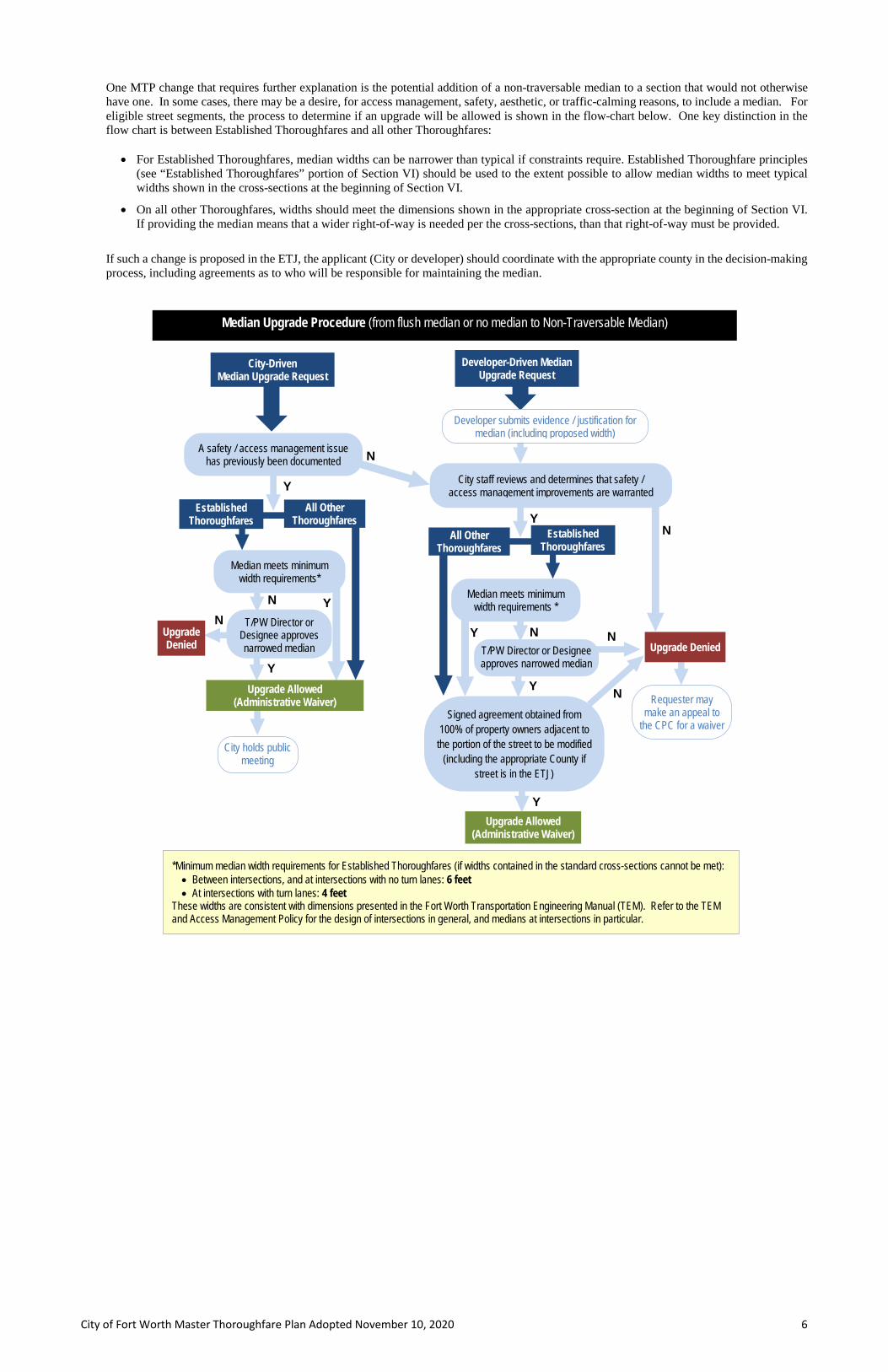
One MTP change that requires further explanation is the potential addition of a non-traversable median to a section that would not otherwise have one. In some cases, there may be a desire, for access management, safety, aesthetic, or traffic-calming reasons, to include a median. For eligible street segments, the process to determine if an upgrade will be allowed is shown in the flow-chart below. One key distinction in the flow chart is between Established Thoroughfares and all other Thoroughfares:
• For Established Thoroughfares, median widths can be narrower than typical if constraints require. Established Thoroughfare principles (see “Established Thoroughfares” portion of Section VI) should be used to the extent possible to allow median widths to meet typical widths shown in the cross-sections at the beginning of Section VI.
• On all other Thoroughfares, widths should meet the dimensions shown in the appropriate cross-section at the beginning of Section VI. If providing the median means that a wider right-of-way is needed per the cross-sections, than that right-of-way must be provided.
If such a change is proposed in the ETJ, the applicant (City or developer) should coordinate with the appropriate county in the decision-making process, including agreements as to who will be responsible for maintaining the median.
N
Y
N
City holds public meeting
Signed agreement obtained from 100% of property owners adjacent to
the portion of the street to be modified (including the appropriate County if
street is in the ETJ)
N
Developer-Driven Median Upgrade Request
Requester may make an appeal to
the CPC for a waiver
Upgrade Denied
Y
Developer submits evidence / justification for median (including proposed width)
Upgrade Allowed (Administrative Waiver)
A safety / access management issue has previously been documented
Upgrade Denied
N
City staff reviews and determines that safety / access management improvements are warranted
Y
T/PW Director or Designee approves narrowed median
N
Y
T/PW Director or Designee approves narrowed median
Y N
Upgrade Allowed (Administrative Waiver)
Median meets minimum width requirements*
Y
N
Established Thoroughfares
All Other Thoroughfares
Median meets minimum width requirements *
Y
Established Thoroughfares
All Other Thoroughfares
City-Driven Median Upgrade Request
*Minimum median width requirements for Established Thoroughfares (if widths contained in the standard cross-sections cannot be met): • Between intersections, and at intersections with no turn lanes: 6 feet • At intersections with turn lanes: 4 feet
These widths are consistent with dimensions presented in the Fort Worth Transportation Engineering Manual (TEM). Refer to the TEM and Access Management Policy for the design of intersections in general, and medians at intersections in particular.
Median Upgrade Procedure (from flush median or no median to Non-Traversable Median)

City of Fort Worth Master Thoroughfare Plan Adopted November 10, 2020 7
Thoroughfares in the MTP are defined by two primary attributes, described below.
• Alignment: The alignment of each MTP thoroughfare has been tested with the GIS model described in Section I. In a number of cases, multiple alternatives were evaluated for a given alignment. In addition to the quantitative analysis provided by this model, these evaluations also included qualitative evaluations of connectivity, mobility, relationship to other agency plans, and observation of key physical features. This approach, fueled by technology and tools not necessarily available for past MTPs, has allowed the development of alignments intended to minimize impact and cost. As described in Section II, alignments within 1,000 feet of the MTP alignments can be accepted by the City without an MTP amendment, but larger deviations must be considered for MTP amendments and must provide equivalent or superior connectivity and functionality.
• Right-of-Way: To determine the appropriate right-of-way widths for thoroughfares in the MTP, a selection process is used to identify a roadway
cross-section essentially based on a series of questions. This Typical Section Selection Process is illustrated in simplified form below, and in detail on the following page. This process has been used to select sections and compute rights-of-way for this MTP, and is applicable for amendments and updates going forward.
The selection process uses three general categories of inputs:
• A series of maps presented in this MTP and elsewhere: the Street Type Map, the Lanes Map, the Bicycle Network Map (from the Fort Worth Active Transportation Plan), and the “Transit Vision: Major Services” map (from Trinity Metro’s Master Plan).
• Quantitative data about the thoroughfare: automobile target speed (a function of the Street Type), average daily traffic (ADT) volume forecasts, and driveway density.
• Special corridor designations (explained in more detail in Section V): Roundabout Corridor, Aesthetic Corridor, and Special Residential Section.
Ultimately, each selection process results in a code and implied right-of-way, such as:
NCO – L2 – T0 – NTMS – P0 – BLS (110’)
Applying the MTP II
Source: Street Type Map
Which of the 5 Street Types?
How many lanes per direction?
What type of special transit facility
(if any)?
Source: Lanes Map
Source: Transit Moves Fort Worth and ongoing coordination with
Trinity Metro
What type of median (if any)?
Based on: traffic volumes,
number of lanes, transit median
(if any), and
other corridor features
What type of parking (if any)?
Based on: traffic volumes
and number of lanes
What type of bike facility?
Source: Fort Worth Active
Transportation Plan, auto traffic volumes, auto traffic speeds
parking type, and
other corridor features
TYPE
Options: dedicated
transit lane, peak-hour
transit lane, or
transit median
Options: Two-way left-turn
lane, narrow median, standard median,
wide median, or transit median
Options: Parallel
or Diagonal
Options: Shared lane,
conventional bike lane, buffered bike lane,
separated bike lane, off-street sidepath
Street Type
Lanes
Transit
Median
Parking
Bikes
Typical Section Selection Process (Simplified)
Street Type = Neighborhood
Connector
Two through
lanes per direction
No special transit facility
Standard-width non-traversable
median
No on-street
parking
Separated bike lane
Right-of-way width = 110’

City of Fort Worth Master Thoroughfare Plan Adopted November 10, 2020 8
Ty
pica
l Sec
tion
Selec
tion
Proc
ess f
or T
horo
ughf
ares

City of Fort Worth Master Thoroughfare Plan Adopted November 10, 2020 9
The primary categorization for thoroughfares in Fort Worth is the Street Type. Rather than categorizing thoroughfares solely on the basis of traffic volumes and speeds, the MTP categorizations are designed to reflect streets’ respective land-use contexts, and a balanced approach to the various transportation modes needing to use each Street Type.
The Street Type concept covers all thoroughfares in the City and Extraterritorial Jurisdiction (with the exceptions noted below), including those that have already been built. Thus, the plan has an aspirational component, with the ultimate goal of transforming the thoroughfare network into a world-class Complete Streets system. More discussion of already-built thoroughfares can be found under “Established Thoroughfares” in Section IV. The MTP includes five Street Types, as illustrated on the following page. The figure includes a narrative description of each Street Type and several representative images. The page after the descriptions includes a map showing how these Street Types are assigned to the city’s thoroughfare network. Segment Lengths The Street Type can vary over a given thoroughfare’s length, as is evidenced by the Street Type map. As the character along different segments of a thoroughfare changes, it is appropriate for the Street Type to vary to fit each context. The table at right indicates typical minimum desirable lengths for continuous segments of each Street Type. Street Types should be amended on thoroughfares when zoning or future land use changes are modified, in accordance with the typical minimum segment lengths table. Street Type Exceptions Special Districts Although the Street Type system is designed to cover all thoroughfares in the city, certain pre-existing special districts within the city already have established street designations and design standards. These districts include:
• Trinity Lakes (I-820/Trinity Boulevard) • Panther Island (just north of Downtown) • Stockyards Historic and Form-Based Code District
The transportation plans and standards in these districts supersede those of the MTP, and are incorporated into the MTP by reference.
Park-Adjacent Streets There is no separate “Park Street” included in the MTP, but when a thoroughfare is adjacent to a park, the frontage zone should be eliminated, and the extra width shifted to the clearance and furnishing zones, so that the pedestrian zone, sidewalk or sidepath abuts the right-of-way line. (See Section VI for definitions of frontage zone, clearance/furnishing zone, pedestrian zone, sidepath, and sidewalk.)
Non-Thoroughfare Streets Collectors Collector streets are not thoroughfares, and thus are not mapped in the MTP. However, they provide extremely important supporting connections to the City’s overall transportation system, moving traffic from local streets and developments to thoroughfares. A well-designed collector network can reduce overall traffic pressure by allowing shorter, more local trips to be made off the thoroughfare network. Thus, the spacing or “density” of collectors throughout the roadway network is an important component of an efficient and successful transportation system. The City’s Subdivision Ordinance provides more detail on collector spacing, design, and planning requirements. Cross-sections for collectors are provided in Section VI. Local Streets Local streets are also not mapped in the MTP, but cross-sections are provided in Section VI.
Typical Minimum Continuous Segment Length
, Single block
, ½ mile
2 miles
Commerce/Mixed-Use Street Activity Street
Commercial Connector Neighborhood Connector
System Link
Street Types III
City of Fort Worth Master Thoroughfare Plan Adopted November 10, 2020 10
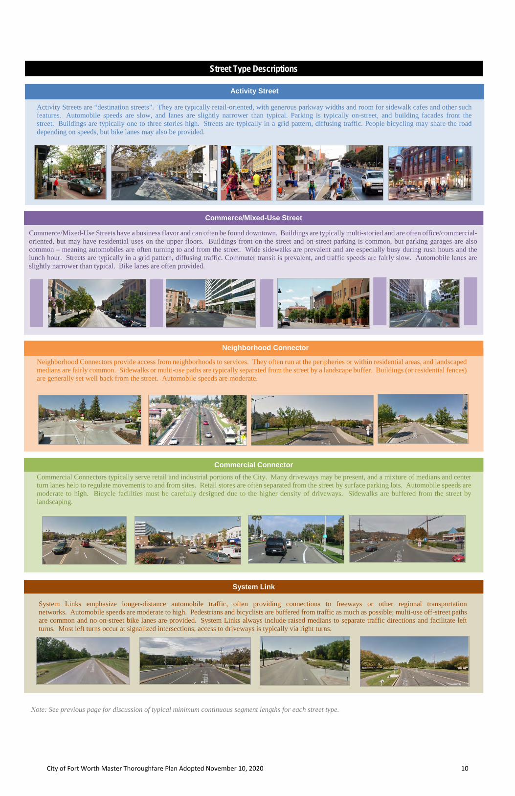
Activity Street
Activity Streets are “destination streets”. They are typically retail-oriented, with generous parkway widths and room for sidewalk cafes and other such features. Automobile speeds are slow, and lanes are slightly narrower than typical. Parking is typically on-street, and building facades front the street. Buildings are typically one to three stories high. Streets are typically in a grid pattern, diffusing traffic. People bicycling may share the road depending on speeds, but bike lanes may also be provided.
Neighborhood Connectors provide access from neighborhoods to services. They often run at the peripheries or within residential areas, and landscaped medians are fairly common. Sidewalks or multi-use paths are typically separated from the street by a landscape buffer. Buildings (or residential fences) are generally set well back from the street. Automobile speeds are moderate.
Commerce/Mixed-Use Street
Commerce/Mixed-Use Streets have a business flavor and can often be found downtown. Buildings are typically multi-storied and are often office/commercial-oriented, but may have residential uses on the upper floors. Buildings front on the street and on-street parking is common, but parking garages are also common – meaning automobiles are often turning to and from the street. Wide sidewalks are prevalent and are especially busy during rush hours and the lunch hour. Streets are typically in a grid pattern, diffusing traffic. Commuter transit is prevalent, and traffic speeds are fairly slow. Automobile lanes are slightly narrower than typical. Bike lanes are often provided.
Neighborhood Connector
Commercial Connector Commercial Connectors typically serve retail and industrial portions of the City. Many driveways may be present, and a mixture of medians and center turn lanes help to regulate movements to and from sites. Retail stores are often separated from the street by surface parking lots. Automobile speeds are moderate to high. Bicycle facilities must be carefully designed due to the higher density of driveways. Sidewalks are buffered from the street by landscaping.
System Link
System Links emphasize longer-distance automobile traffic, often providing connections to freeways or other regional transportation networks. Automobile speeds are moderate to high. Pedestrians and bicyclists are buffered from traffic as much as possible; multi-use off-street paths are common and no on-street bike lanes are provided. System Links always include raised medians to separate traffic directions and facilitate left turns. Most left turns occur at signalized intersections; access to driveways is typically via right turns.
Street Type Descriptions
Note: See previous page for discussion of typical minimum continuous segment lengths for each street type.

City of Fort Worth Master Thoroughfare Plan Adopted November 10, 2020 11
Street Type Map

City of Fort Worth Master Thoroughfare Plan Adopted November 10, 2020 12
The Lanes Map (next page) shows the ultimate number of automobile through lanes prescribed for Fort Worth’s Thoroughfares, not including turn lanes, transit lanes, parking lanes, or bike lanes. Many of the typical sections include a continuous center Two-Way Left-Turn Lane (TWLTL). When a TWLTL is included, a street with two automobile through lanes (one per direction) is often referred to as a “three-lane street”, and a street with four automobile through lanes (two per direction) as a “five-lane street”. To avoid confusion with these numbering conventions, the map does not explicitly indicate the presence of TWLTLs or medians – although the Typical Section Selection Process (Section II) and Appendix A indicates when they should be used. It is worth noting that a small number of segments are shown with three (3) lanes per direction on the Lanes Map, and are also identified as Neighborhood Connectors on the Street Type Map. The MTP encourages Neighborhood Connectors to have two (2) or fewer lanes per direction, given their context. However, in some cases, the future capacity needs are so great that the MTP Team has introduced two sections that provide the higher-capacity option. Even with this option available, Neighborhood Connectors with three (3) lanes per direction should be avoided as a matter of course. They may be needed in rare, extreme cases, but should not be considered the norm. Note that the Lanes Map also does not address auxiliary or turn lanes at intersections or interchanges: • The median (or TWLTL) widths on most MTP sections typically allow for a single left-turn lane to be provided at intersections. Only a few
System Link sections explicitly provide wide medians, which would allow for dual left-turn lanes at intersections. However, at some intersection approaches with a single left-turn lane, dual left-turn lanes might ultimately be warranted. See the Access Management Policy and Transportation Engineering Manual for more information.
• None of the sections provide explicit right-turn lane provisions, with the exception of dedicated transit lanes (notated as “bike + transit”) which can often facilitate right turns at intersections. See the Access Management Policy for more information on when right-turn lanes are allowed.
• Often, approaching interchanges, the number of through lanes needs to be supplemented by auxiliary through lanes that ultimately become turn
lanes at the interchange ramps. These auxiliary lanes are generally not reflected in the Lanes Map, and need to be evaluated when interchange improvements are being considered. See the Access Management Policy for requirements for auxiliary lanes.
Thus, additional considerations for intersections are necessary independent of the MTP. Section VII includes additional discussion regarding intersections and their relationship to the MTP.
Established Thoroughfares For much of the central city (and beyond), transportation infrastructure is already built to its fully planned dimensions and/or is constrained by existing development. The MTP delineates these streets as Established Thoroughfares. Generally, no major future changes would be expected on these streets, unless one of the items in the three bullets below might occur. Any changes must follow the Width Ranges table in the “Established Thoroughfares” portion of Section VI. Such changes could be subject to a waiver, as defined in Section I, if width ranges of cross-sections are outside the specified parameters. City Council approval is required if a project proposes to increase or decrease the existing number of through lanes.
• A resurfacing project presents an opportunity to restripe the road to allow lanes to be narrowed, bike or transit lanes to be added, and/or lanes to
be removed through a road right-sizing as appropriate. • A City-led capital improvement project within the right-of-way, such as a revitalization/streetscape-type project, would present opportunities to
reconfigure both the parkway and the street, including potentially moving curbs. • A major redevelopment project could present opportunities to completely reimagine the street, including potential adjustments to right-of-way
as well as all of the cross-section elements within the segment of roadway. Because many of the Established Thoroughfares are constrained and may never undergo substantial modifications related to vehicle capacity, MTP guidance is focused on capitalizing on opportunities afforded by the types of projects listed above, in order to allow these thoroughfares to evolve in the direction of the Complete Streets ideals of the MTP. For this reason, the Lanes Map does not include a capacity or cross-section recommendation for these streets, although the Street Type Map does. Roadway changes on Established Thoroughfares should be handled on a case-by-case basis. Guidance for Established Thoroughfares centers around best achieving the goals of each Street Type and is provided in Section VI of this document. It should be noted that an appreciable subset of the Established Thoroughfares are within the Downtown and Near Southside Districts. Although the principles of the MTP must be adhered to in these areas, changes proposed on Established Thoroughfares within these districts should also be informed by the Districts’ guiding documents, especially within the parkways:
- Downtown Urban Design Standards and Guidelines - Near Southside Standards and Guidelines - Berry/University Form Based Code District - Panther Island - Stockyards Historic and Form Based Code District
Excess Right-of-Way In some instances, thoroughfares in Fort Worth have been built inside a greater right-of-way than may be called for in the MTP. In other instances, an amount of right-of-way greater than the MTP might require may have been reserved for a future roadway that hasn’t yet been built. In such cases, the MTP should not be construed to mandate narrowing the right-of-way. Rather, flexibility and creativity are encouraged in determining the best approach to meet the City’s transportation, land-use, and place-making goals. Alternatives such as wider parkways – with room for additional landscaping, sidewalks, trails, or street furniture – should be considered alongside alternatives such as realigning centerlines to allow the recapture of property for future development. See Section I for applicable waiver processes. Special Districts
As described in Section III, certain pre-existing special districts within the city already have established street designations and design standards. The planned lane configurations in these districts supersede those of the MTP, and are incorporated into the MTP by reference.
Roadway Capacity (Through Lanes) IV

City of Fort Worth Master Thoroughfare Plan Adopted November 10, 2020 13
Lanes Map

City of Fort Worth Master Thoroughfare Plan Adopted November 10, 2020 14
In addition to the Street Type Map and Lanes Map, several other map- and corridor-based inputs feed the Typical Section Selection Process (from Section II) that underlies the ultimate determination of thoroughfare right-of-way. These are described below.
ATP Bicycle Network
The Active Transportation Plan (ATP) includes a map of the City’s existing and future Bicycle Network. This map contains three designations: Sidepath, Bike Facility, and None. This map, external to the MTP (a thumbnail is shown at right), can be referred to when applying the Typical Section Selection flow-chart in order to assign bicycle facility types for each of these three designations, on each of the five Street Types. On-Street Bikes Recommended In general, the preference of the Active Transportation Plan, and therefore the MTP, is to accommodate bicyclists off-street (using a sidepath/shared-use path) wherever possible. One MTP exception to this occurs when thoroughfares are in denser areas that may have a proliferation of driveways. In these instances, bicyclists tend to be more visible, and to have fewer driveway conflicts, on the street in a buffered bike lane. The map on the next page illustrates corridors where on-street bicycles are favored; the Typical Section Selection flow-chart provides guidance on how/when to use the map in bicycle facility selection.
Transit
Transit service in Fort Worth is primarily provided by Trinity Metro (formerly known as the T), and existing services include a network of fixed-route bus service, door-to-door paratransit service, and commuter rail service via TEXRail. Trinity Metro also jointly operates the Trinity Railway Express (TRE) through a partnership with Dallas Area Rapid Transit (DART). The City of Fort Worth initiated Transit Moves Fort Worth (TMFW) to expand on the 2015 Transit Master Plan. The TMFW plan has identified and mapped a recommended scenario that includes an implementation plan for future high capacity transit, frequent bus service, and regional and commuter services. Although TMFW does not assign special transit lane treatments (such as center running or dedicated bus lanes) to specific thoroughfares, these types of facilities are likely to be part of Fort Worth’s transportation system in the future. Thus, ongoing coordination between the City and Trinity Metro is critical to thoroughfare planning. As thoroughfare corridors are developed and redeveloped, especially on routes designated as high capacity and frequent service routes, regular and close coordination should occur with Trinity Metro. Additionally, on all roadway projects along existing and planned transit routes, coordination with Trinity Metro is essential to ensure proper bus stop facilities, ADA access, sidewalks, and traffic signal coordination (including transit signal priority).
Special Residential Sections
The Neighborhood Connector Street Type includes several cross-sections labeled “Special Residential Sections”. These sections allow residential units to face the right-of-way without directly fronting the roadway, by providing median-separated one-way frontage / access roads that also include on-street parking. A key consideration in the implementation of these sections is the design of access to and from the frontage roads. Special Residential Sections are not explicitly designated or mapped by the MTP, but are an option on Neighborhood Connectors with two lanes plus a TWLT, four lanes plus a TWLT, or four lanes plus a standard median. They allow developers to consider residential subdivision designs other than those where backyard fences front the street. This decision to use a Special Residential Section is made externally to the Typical Section Selection flow-chart, and should include an engineering review of conceptual designs with a careful eye toward frontage road access.
Single-Lane Roundabout Corridors
On thoroughfares where single-lane roundabouts are, or are planned to be, the primary form of intersection control (no signals), the MTP sections with narrow medians (for Activity Streets and Neighborhood Connectors) are an option. These medians provide a traffic-calming function and provide the minimum width necessary for pedestrian crossing refuge, but are not wide enough to store vehicles for mid-block left turns. Roundabouts facilitate U-turns at intersections, and thus can provide mid-block access while keeping the street section narrow. Roundabout Corridor lengths could be as short as the distance between two roundabout intersections, or they could be multiple miles long. Like Special Residential Sections, Roundabout Corridors are not explicitly designated or mapped by the MTP. However, roundabouts are becoming an increasingly common form of intersection control in Fort Worth, and therefore multi-roundabout corridors will also become increasingly prevalent in the city. Thus, with an engineering study approved by T/PW, the Roundabout Corridor option can be selected on the Typical Section Selection flow-chart. Aesthetic Corridors Narrow medians can also be used on what the MTP terms “Aesthetic Corridors”. These are Neighborhood Connectors or Activity Streets with one through lane per direction, on which it is desired to make an additional investment in streetscape, traffic calming, and place-making. The cross-sections provided by the MTP provide enough flex space that left-turn lanes can be provided at intersections, but if turn lanes cannot be provided, Aesthetic Corridors should not be considered on thoroughfares carrying more than 5,000 vehicles per day. The decision to provide an Aesthetic Corridor must be approved by T/PW.
Multi-Modal Resources and Special Corridors V

City of Fort Worth Master Thoroughfare Plan Adopted November 10, 2020 15
Locations Where On-Street Bikes are Recommended

City of Fort Worth Master Thoroughfare Plan Adopted November 10, 2020 16
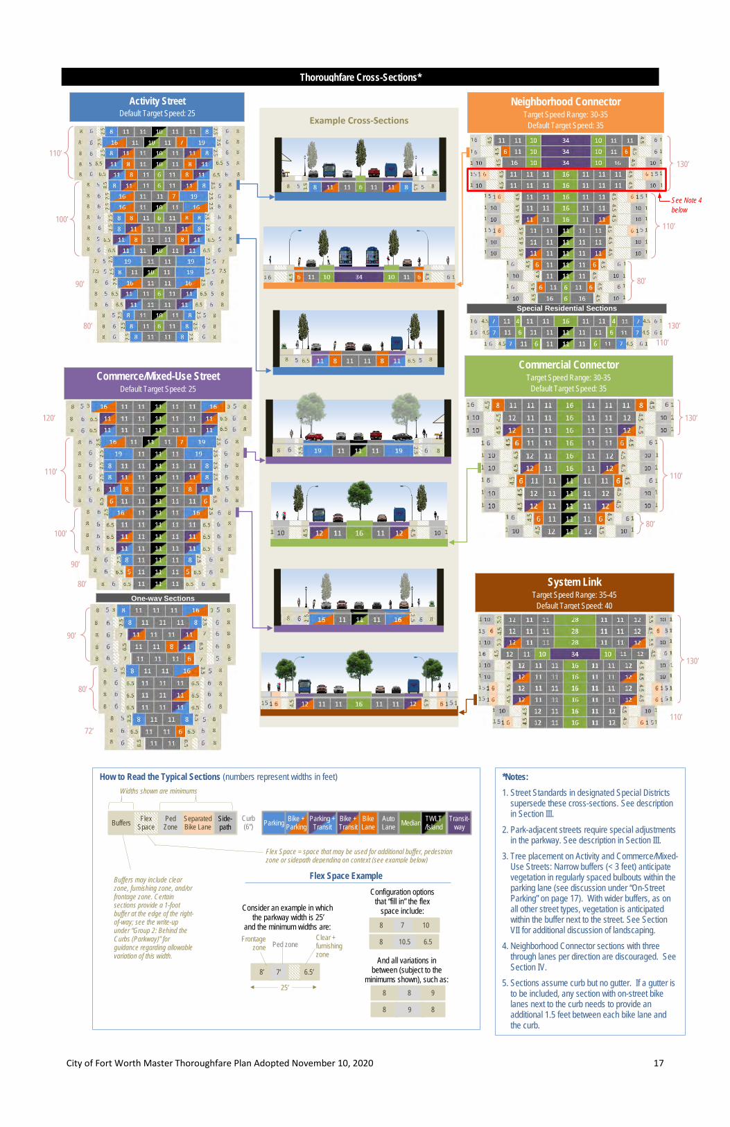
The previous sections of this document have described the steps in the Typical Section Selection process. The diagrams on the next page illustrate the suite of cross-sections that are associated with each Street Type. The particulars of the section elements are described on subsequent pages, and the concept of target speed (also shown on the diagrams) is described below. Target Speed The MTP uses the concept of Target Speed: the speed at which the road designer intends for motorists to travel. Target speed has become an important element of a Complete Streets and Safe Systems approach to roadway design. This approach attempts to control vehicle speeds via means beyond horizontal and vertical curvature; most notably, via lane widths and vertical elements (such as street trees). Although universally accepted standards do not currently exist, lane widths narrower than the traditional 12 feet are used to promote lower speeds while narrowing the road width and thus reducing pedestrian crossing exposure. The section diagrams indicate both a target speed range and a default target speed. The default target speed should be used in the design of all roadway elements, including horizontal and vertical curvature, and should ultimately be the posted speed limit. Deviations from the default target speed are considered exceptions, can only occur within the ranges (if there are any) prescribed for each Street Type, and must be approved by T/PW based on an engineering analysis that justifies the exception. See the Transportation Engineering Manual for more details. Several sections of the Texas Transportation Code govern the ability of Texas municipalities to set speed limits. Relevant portions are described below, in relevant order:
Sec. 545.351 (a) describes motorists’ responsibility to drive at reasonable and prudent speeds based on conditions.
Secs. 545.352 (a) and (b) set a lawful speed of 30 miles per hour in an urban district (essentially a city) and characterize exceeding that speed as unlawful.
Secs. 545.356 (a) and (b) allow a City to alter speed limits based on an engineering and traffic investigation, but prohibit lowering the limit below 25 miles per hour (and only allow speeds this low on two-lane undivided facilities).
Distilling these provisions down to the essentials relevant to the MTP:
• The prima facie speed limit on non-state roadways within Fort Worth is 30 mph. • The City can justify higher or lower speeds on the basis of an engineering and traffic investigation. • The City can lower speeds to 25 mph, but not lower, and only on facilities with one lane per direction.
Thus, target speeds in the MTP are set no lower than 25 mph. One-Way Streets Commerce/Mixed Use Streets include a series of one-way cross-sections in addition to the standard two-way cross-sections. Although none of the city’s future thoroughfares are expected to be built as one-way streets, several of the Established Thoroughfares in the Downtown area operate as one-way streets. And while even many of these may someday be converted to two-way operations, it is probable that some will remain as one-way streets and will potentially be subject to an improvement project in the future. Thus, the one-way cross-sections are provided to assist in transitioning to a more Complete Streets configuration. One-way streets are not explicitly included in the Typical Section Selection process described in Section II. Generally speaking, the multi-modal section elements (bike, bus, and parking lanes) can be selected using the Typical Section Selection flow-chart, although any traffic-volume-related criteria should be halved.
Typical Sections VI
City of Fort Worth Master Thoroughfare Plan Adopted November 10, 2020 17
Commercial Connector Target Speed Range: 30-35
Default Target Speed: 35
130’
110’
80’
Flex Space Example
Consider an example in which the parkway width is 25’
and the minimum widths are:
And all variations in between (subject to the
minimums shown), such as:
10 7 8
6.5 10.5 8
How to Read the Typical Sections (numbers represent widths in feet)
Thoroughfare Cross-Sections*
Example Cross-Sections
120’
110’
90’ 80’
100’
90’
80’
72’
Commerce/Mixed-Use Street Default Target Speed: 25
One-way Sections
Widths shown are minimums
8 8 9
8 9 8
Activity Street Default Target Speed: 25
110’
100’
90’
80’
130’
110’
110’
80’
130’
Neighborhood Connector Target Speed Range: 30-35
Default Target Speed: 35
Special Residential Sections
System Link Target Speed Range: 35-45
Default Target Speed: 40
130’
110’
See Note 4 below
Configuration options that “fill in” the flex
space include:
6.5’ 8’ 7’
Frontage zone
Clear + furnishing zone
Ped zone
25’
Buffers may include clear zone, furnishing zone, and/or frontage zone. Certain sections provide a 1-foot buffer at the edge of the right-of-way; see the write-up under “Group 2: Behind the Curbs (Parkway)” for guidance regarding allowable variation of this width.
Flex Space = space that may be used for additional buffer, pedestrian zone or sidepath depending on context (see example below)
Buffers Parking Auto Lane Median Transit-
way TWLT /Island
Bike + Parking
Curb (6”)
Flex Space
Ped Zone
Side-path
Bike Lane
Bike + Transit
Parking + Transit
Separated Bike Lane
*Notes: 1. Street Standards in designated Special Districts
supersede these cross-sections. See description in Section III.
2. Park-adjacent streets require special adjustments in the parkway. See description in Section III.
3. Tree placement on Activity and Commerce/Mixed-Use Streets: Narrow buffers (< 3 feet) anticipate vegetation in regularly spaced bulbouts within the parking lane (see discussion under “On-Street Parking” on page 17). With wider buffers, as on all other street types, vegetation is anticipated within the buffer next to the street. See Section VII for additional discussion of landscaping.
4. Neighborhood Connector sections with three through lanes per direction are discouraged. See Section IV.
5. Sections assume curb but no gutter. If a gutter is to be included, any section with on-street bike lanes next to the curb needs to provide an additional 1.5 feet between each bike lane and the curb.

City of Fort Worth Master Thoroughfare Plan Adopted November 10, 2020 18
Typical Section Elements
The following pages describe the elements that make up each section. The section elements are divided into two general areas of the right-of-way: (1) between the curbs (on-street + median) and (2) behind the curbs (within the parkway). The graphic at right illustrates these two areas; as in the graphic, the roadway elements in the section diagrams are darker with white text, and the parkway elements are more muted with dark text. Note that all sections are generally symmetrical; elements that appear on one side of the road are mirrored on the other side. The only exception is asymmetrical parking, described under below. Group 1: Between the Curbs (Roadway) The roadway area can support movements of personal and commercial motorized vehicles, transit vehicle operations, bicycle movements, and parking/loading operations. It may also include a median for separating opposing directions of travel. The default street section assumed in the MTP is a monolithic section constructed of concrete, with the curbs integrated as a continuous element of the cross-section. This means that no designated gutter separates the travel way (or parking area) from the curb. All outer dimensions are measured to the face of curb; and the standard curb is 6 inches wide. The case in which a section is built with gutters (generally an asphalt roadway and a concrete gutter) represents a departure from the assumptions of the MTP. The City’s standard gutter is roughly 1.5 feet wide. For sections that include bike lanes adjacent to the curb, the bike lane dimensions should be increased by 1.5 feet in order to provide clearance from the lip of gutter. For all remaining sections (those with automobile travel lanes or parking in the outside lane), lateral dimensions do not need to be adjusted. Note that the Special Districts mentioned in Section III may have differing width requirements; the standards for these districts should be consulted as appropriate.
Automobile lanes need to be wide enough to safely carry not only passenger cars, but buses, trucks, and emergency vehicles as well. However, excessive widths can encourage excessive speeds. Thus, the MTP strives for a balance that harmonizes both mobility and safety. The default lane width in the MTP is 11 feet. The exceptions are as follows:
• On the single Neighborhood Connector section that includes one through lane in each direction, a raised median, and no parking or bike lanes, the through lanes are 16 feet wide. Because the single lane is located, unbuffered, between a curb and a median (vertical barriers on both sides), extra width is provided so that a disabled and/or stopped vehicle will not block traffic.
• For the Commercial Connector and System Link sections, through lanes next to the outside curb are 12 feet wide (measured from face of curb), reflecting the fact that heavy vehicles are more prevalent on these Street Types, and – especially on Commercial Corridors – the number of turns to and from commercial driveway can be heavy.
• Travel lanes must not exceed the identified width without a waiver through the City Plan Commission.
Every automobile lane in the MTP is sized to provide the ability to accommodate transit buses, so general transit routes can run on any thoroughfare in Fort Worth. However, some MTP cross-sections allow for the provision of special transit lanes, which fall in the three categories described below.
Transit Median
Transit medians, discussed more fully under , are intended to
accommodate one transit vehicle in each direction. Additional width is included for potential passenger platform areas and to accommodate left-turn lanes at intersections. See the transit discussion in Section V for further transit options and linkages to transit plans.
Dedicated Transit Lane
,
Dedicated transit lanes are reserved for exclusive, continuous use by transit vehicles at all times of the day. They are also potentially available for use by bicycles, since (1) bus traffic is fairly infrequent, and (2) bus operators are professional drivers who are (or can be) trained to correctly share the lane with bicyclists. All five Street Types include sections with dedicated transit lanes.
Transit + Parking
Some transit lanes are only needed for certain peak periods of the day. During the remainder of the day, they can be used for on-street parking. Only Activity Streets and Commerce/Mixed-Use Streets include this section element, because they are the only Street Types that allow on-street parking.
10 34 10
Median / Center Treatments
12 11
11
On-Street Parking
Automobile Through Lanes
Special Transit Lanes
Roadway Parkway Parkway

City of Fort Worth Master Thoroughfare Plan Adopted November 10, 2020 19
All street cross-sections in the MTP are intended to include some level of bicycle access, whether on-street or off-street, implicit or explicit. The philosophy of the MTP and ATP is to provide a low-stress bicycle network that is as inviting as to possible to both expert and non-expert cyclists alike. This means providing off-street facilities (sidepaths or shared-use paths) on higher-volume, higher-speed streets where feasible, and on-street facilities on streets with low to moderate motorized vehicle volumes and speeds. The descriptions below cover the on-street provisions of the MTP cross-sections. See the Active Transportation Plan, and the “Established Thoroughfares” portion of this chapter, for more information on appropriate application of these facilities on Established Thoroughfares.
Shared Lane
,
On low-speed streets, it is often appropriate and acceptable to allow bicyclists to share automobile traffic lanes. Only Activity Streets and Commerce/Mixed-Use Streets provide this option, and any section on these Street Types that does not include an explicit bike facility (either on-street or off-street) is intended to operate as a shared facility. Note that on the Special Residential Sections of Neighborhood Connectors, bicycles are intended to use the frontage roads (due to their low automobile traffic volume). Often, shared facilities are signed and/or marked with a sharrow (see photo).
Conventional Bike Lane
,
Conventional Bike Lanes are dedicated, striped lanes (see photo at right). In general, conventional bike lanes in the MTP are 6 feet wide, with the exception of the narrowest Commerce/Mixed-Use section, which has a 5-foot-wide bike lane due to generally lower automobile speeds. Activity Streets don’t provide sections with conventional bike lanes, because all Activity Streets include on-street parking. System Links don’t provide conventional bike lanes, because the volumes and speeds are better suited to off-street bike facilities. The remaining Street Types include sections with conventional bike lanes.
Buffered
Bike Lane
,
Some sections include an extra striped buffer area adjacent to the bike lane, for two primary purposes:
• To provide separation between parked cars and the bike lane on Activity Streets and Commerce/Mixed-Use Streets. Adjacent to parallel parking (first picture), this takes the form of a 3-foot buffer next to a 5-foot lane (total width of 8 feet), to keep the “door zone” clear. Adjacent to diagonal parking, this takes the form of a 2-foot buffer next to a 5-foot lane (total width of 7 feet).
• To provide an additional cushion between bicyclists and moving automobiles (second picture) on some of the widest Commercial Connectors – again, a 5+3 = 8-foot total lane. (System Links provide off-street options to separate bike traffic from the street.)
At times, physical barriers (delineators, curbing, etc.) are used inside the buffer. Depending on the type and extent of the barrier, this is sometimes referred to as a “protected bike lane”, “separated bike lane”, or “cycle track”.
Bike + Parking
Some of the Activity Street and Commerce/Mixed-Use Street sections show a 16-foot bike/parking area. The default configuration for this option is to place a buffered bike lane (5 +3 = 8 feet wide) on the street side of an 8-foot parking lane (as in the first picture at right). However, in cases where on-street parking is longer-term, and foot traffic to and from parked cars is moderate (more likely on Commerce/Mixed-Use Streets), this arrangement can be flipped (with the same dimensions) to place the buffered bike lane on the curb side of the parking, creating a parking-protected bike lane (as in the second picture at right).
Bike + Transit
,
As mentioned under , several cross-sections provide dedicated transit lanes. These lanes can also potentially be used by bikes, since they will experience fairly infrequent motorized vehicle traffic. One exception relates to System Links, which, in absence of these transit lanes, would provide only off-street bike lanes. However, since System Links provide off-street options, non-expert riders can choose not to ride in the street, while more expert riders can choose to ride in the street where dedicated transit lanes are provided.
The list of bicycle treatments included in the MTP is not exhaustive; for example, street-level separated bike lanes (also known as protected bike lanes or cycle tracks) are not included. Such exclusions do not imply that alternative treatments are discouraged or forbidden in Fort Worth; on the contrary, they are welcome to be considered for individual projects on a case-by-case basis if warranted. But the MTP’s approach to bicycle facilities is emblematic of the overall Street Type approach: in order to ensure that a desired aspect of the system (in this case, a robust bicycle network) is realized, very specific facility types are applied, with very specific criteria, to each Street Type. This systematic and defined approach is oriented toward reserving necessary right-of-way to provide context-appropriate provisions for all road users. See the adopted Active Transportation Plan and Transportation Engineering Manual for additional guidance on planning and designing bicycle facilities.
12 11
6 5
8 7
16
12
11
Special Transit Lanes
On-Street Bicycle Facilities

City of Fort Worth Master Thoroughfare Plan Adopted November 10, 2020 20
Center treatments on thoroughfares vary from a simple double-yellow striped centerline to extra-wide non-traversable medians.
Undivided
A few of the Activity Street sections do not include any width-extending center treatments. These sections constitute undivided roadways with one lane in each direction and a painted centerline. The MTP does not include undivided sections with multiple lanes per direction, as these are undesirable from a safety and capacity standpoint. Because thoroughfares typically carry moderate to high automobile traffic volumes, these sections will be somewhat rare. In some cases, turn lanes at intersections could require additional right-of-way (see “Intersections” in Section VII).
Two-Way Left-Turn Lane (TWLTL)
,
This treatment consists of a striped center lane from which left turns can be made by vehicles in either direction. TWLTLs maximize access to adjacent land uses, while promoting capacity by removing left-turn movements from the through travel stream. Portions of the lane can also include non-traversable medians to provide pedestrian refuge or to prevent turns (see second photo). At higher volumes/speeds (and on roadways with 3 or more lanes in each direction), TWLTLs are not appropriate – thus, neither System Links nor six-lane Commercial Connectors include them. In addition, the MTP allows the “upgrading” of TWLTLs to non-traversable medians in certain situations, as described in the “Change/Exception Process” portion of Section I.
Non-Traversable Median (NTM) – The remaining median treatments fall in this category, and constitute vertical barriers between directions of travel. Typically, medians are raised (as opposed to depressed), as shown in most of the photos below. Landscaping – especially vertical features such as trees and taller shrubs, close to the travel way – is an important element of a Complete Streets approach to calming traffic. See “Complete Streets Landscaping Elements” in Section VII for further guidance. Medians typically have openings at intersections and major driveways; see “Access Management” in Section VII.
Standard
Standard medians are provided on Neighborhood Connectors, Commercial Connectors, and System Links. They provide the dual function of controlling access between intersections, and accommodating single left-turn lanes at intersections. Note that corridors with standard medians may certainly contain intersections that need dual left-turn lanes; see “Intersections” in Section VII.
Wide
Wide medians are included for corridors on which dual left-turn lanes are expected to be prevalent. For MTP purposes, they are included only as an option for System Links with three lanes in each direction.
Narrow
An option on Activity Streets and certain Neighborhood Connectors, where volumes are low and/or left-turning needs are minimal, narrow medians are generally applicable in two situations:
• On single-lane roundabout corridors, where turns (including U-turns) often occur through the roundabouts. See “Single-Lane Roundabout Corridors” in Section V.
• To provide aesthetics and traffic calming on a roadway with fairly low turning volumes. See “Aesthetic Corridors” in Section V.
Transit
Transit medians are intended to accommodate either dedicated bus lanes (top photo) or center-running light-rail transit (bottom photo) – one transit vehicle in each direction running within the median. Additional width is included on both outside edges of these medians for two purposes: (a) to provide a platform area for waiting transit passengers at stops, and (b) to shadow left-turn lanes at intersections. Transit medians are included as options on Neighborhood Connectors and System Links because these Street Types offer the needed width and generally have the level of access management needed to promote high-capacity transit usage of the median. See the transit discussion in Section V for further transit options and linkages to transit plans.
Depressed median options. Any of the non-traversable median options, except the narrow option, are candidates for consideration for a depressed, rather than raised, configuration in the appropriate circumstances. Depressed medians are often used for stormwater management purposes, in keeping with Green Infrastructure (GI) practices supported by the City. See “Green Infrastructure” in Section VII for further guidance.
11 11
11 10
16
28
6
10 34 10
Median / Center Treatments

City of Fort Worth Master Thoroughfare Plan Adopted November 10, 2020 21
All Activity Street sections include on-street parking, as do many of the Commerce/Mixed-Use Street sections. The remaining Street Types do not include on-street parking, with one exception: the Special Residential Sections, included in the Neighborhood Connector Street Type, which include parking on the frontage roads adjacent to the main thoroughfare.
Parallel
From a Complete Streets standpoint, the most important feature of the parallel parking area is the inclusion of features that essentially narrow the in-street cross-section by incorporating the parking area into the parkway. Regularly spaced curb bulbouts, most desirably used as tree wells (see photo at right for one compact example), are the means of accomplishing this. Note that the parking area can also be designated for loading zones and taxi stands where needed.
Angle/
Diagonal
The width of 19 feet shown in the cross-sections accommodates a 60º stall angle, and the width is the same for both head-in and reverse (back-in) angle parking. Adjacent to bike lanes, reverse angle parking shall always be used. Note that, as with parallel parking, bulbouts / tree wells should be used with angle parking to narrow the effective street width and calm traffic. Shorter bulb-out areas can provide an opportunity for motorcycle parking (see photo), or micromobility (e.g., bike-share station). Angle parking is not used on streets with one automobile through lane in each direction plus a median, because the median would hamper parking access. It is also not used on streets with more than one automobile through lane per direction.
Asymmetrical Parking. Some sections use differing parking types on each side of the road in order to minimize cross-section width. The photo at right shows a section with angle parking on one side and parallel parking on the other. If an asymmetrical section is implemented, traffic calming effects can still be achieved on both sides of the street by alternating, on a block-by-block basis, which side has the angle parking. This technique does not affect the right-of-way or street width, but is mentioned here as a consideration.
Parking +
Bike
When on-street parking is adjacent to a bike lane, there are often two options for positioning the parking: the curb side of the bike lane (first photo), or the street side (second photo). See the discussion under .
Parking + Transit
When a peak-period transit lane is provided (see the discussion under ), the lane can be used for parking during the remainder of the day. In this case, there is no ability to use bulbouts / tree wells, since the lane must be continuously traversable by transit vehicles during peak periods.
8
19 Motorcycle or micromobility parking
allowed here
16 On-street Bicycle Facilities
11
Special Transit Lanes
On-Street Parking
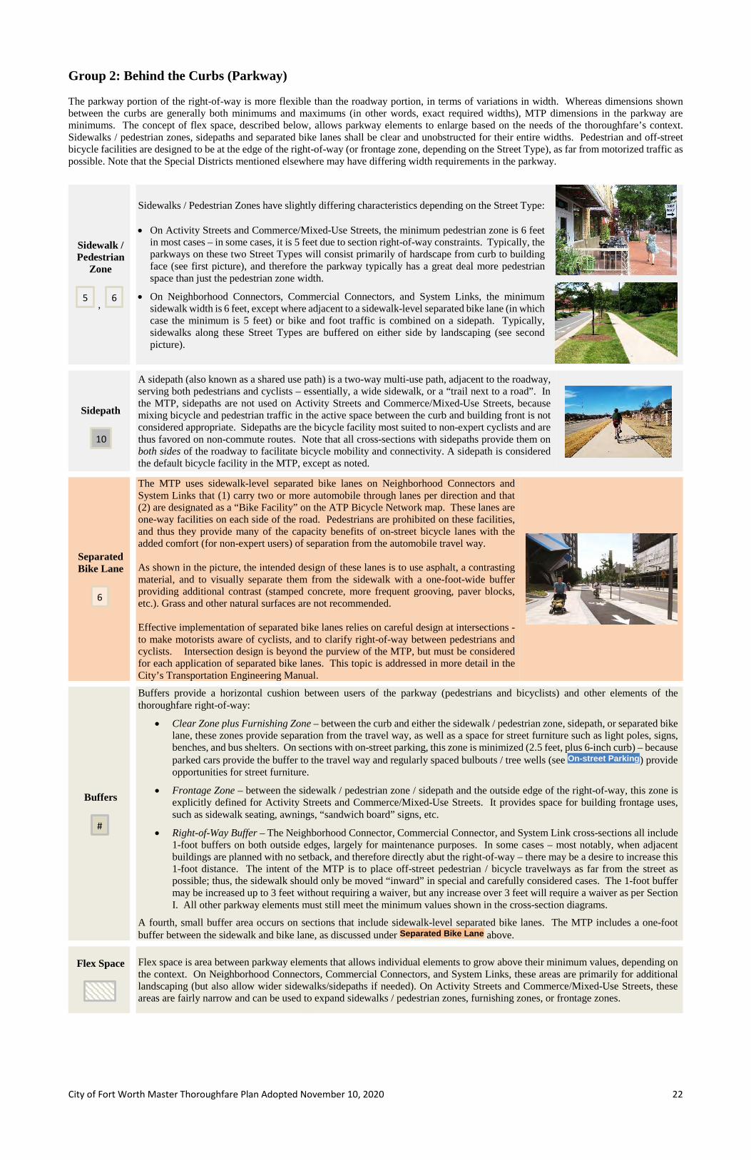
City of Fort Worth Master Thoroughfare Plan Adopted November 10, 2020 22
Group 2: Behind the Curbs (Parkway) The parkway portion of the right-of-way is more flexible than the roadway portion, in terms of variations in width. Whereas dimensions shown between the curbs are generally both minimums and maximums (in other words, exact required widths), MTP dimensions in the parkway are minimums. The concept of flex space, described below, allows parkway elements to enlarge based on the needs of the thoroughfare’s context. Sidewalks / pedestrian zones, sidepaths and separated bike lanes shall be clear and unobstructed for their entire widths. Pedestrian and off-street bicycle facilities are designed to be at the edge of the right-of-way (or frontage zone, depending on the Street Type), as far from motorized traffic as possible. Note that the Special Districts mentioned elsewhere may have differing width requirements in the parkway.
Sidewalk / Pedestrian
Zone
,
Sidewalks / Pedestrian Zones have slightly differing characteristics depending on the Street Type: • On Activity Streets and Commerce/Mixed-Use Streets, the minimum pedestrian zone is 6 feet
in most cases – in some cases, it is 5 feet due to section right-of-way constraints. Typically, the parkways on these two Street Types will consist primarily of hardscape from curb to building face (see first picture), and therefore the parkway typically has a great deal more pedestrian space than just the pedestrian zone width.
• On Neighborhood Connectors, Commercial Connectors, and System Links, the minimum sidewalk width is 6 feet, except where adjacent to a sidewalk-level separated bike lane (in which case the minimum is 5 feet) or bike and foot traffic is combined on a sidepath. Typically, sidewalks along these Street Types are buffered on either side by landscaping (see second picture).
Sidepath
A sidepath (also known as a shared use path) is a two-way multi-use path, adjacent to the roadway, serving both pedestrians and cyclists – essentially, a wide sidewalk, or a “trail next to a road”. In the MTP, sidepaths are not used on Activity Streets and Commerce/Mixed-Use Streets, because mixing bicycle and pedestrian traffic in the active space between the curb and building front is not considered appropriate. Sidepaths are the bicycle facility most suited to non-expert cyclists and are thus favored on non-commute routes. Note that all cross-sections with sidepaths provide them on both sides of the roadway to facilitate bicycle mobility and connectivity. A sidepath is considered the default bicycle facility in the MTP, except as noted.
Separated Bike Lane
The MTP uses sidewalk-level separated bike lanes on Neighborhood Connectors and System Links that (1) carry two or more automobile through lanes per direction and that (2) are designated as a “Bike Facility” on the ATP Bicycle Network map. These lanes are one-way facilities on each side of the road. Pedestrians are prohibited on these facilities, and thus they provide many of the capacity benefits of on-street bicycle lanes with the added comfort (for non-expert users) of separation from the automobile travel way. As shown in the picture, the intended design of these lanes is to use asphalt, a contrasting material, and to visually separate them from the sidewalk with a one-foot-wide buffer providing additional contrast (stamped concrete, more frequent grooving, paver blocks, etc.). Grass and other natural surfaces are not recommended. Effective implementation of separated bike lanes relies on careful design at intersections - to make motorists aware of cyclists, and to clarify right-of-way between pedestrians and cyclists. Intersection design is beyond the purview of the MTP, but must be considered for each application of separated bike lanes. This topic is addressed in more detail in the City’s Transportation Engineering Manual.
Buffers
Buffers provide a horizontal cushion between users of the parkway (pedestrians and bicyclists) and other elements of the thoroughfare right-of-way:
• Clear Zone plus Furnishing Zone – between the curb and either the sidewalk / pedestrian zone, sidepath, or separated bike lane, these zones provide separation from the travel way, as well as a space for street furniture such as light poles, signs, benches, and bus shelters. On sections with on-street parking, this zone is minimized (2.5 feet, plus 6-inch curb) – because parked cars provide the buffer to the travel way and regularly spaced bulbouts / tree wells (see ) provide opportunities for street furniture.
• Frontage Zone – between the sidewalk / pedestrian zone / sidepath and the outside edge of the right-of-way, this zone is explicitly defined for Activity Streets and Commerce/Mixed-Use Streets. It provides space for building frontage uses, such as sidewalk seating, awnings, “sandwich board” signs, etc.
• Right-of-Way Buffer – The Neighborhood Connector, Commercial Connector, and System Link cross-sections all include 1-foot buffers on both outside edges, largely for maintenance purposes. In some cases – most notably, when adjacent buildings are planned with no setback, and therefore directly abut the right-of-way – there may be a desire to increase this 1-foot distance. The intent of the MTP is to place off-street pedestrian / bicycle travelways as far from the street as possible; thus, the sidewalk should only be moved “inward” in special and carefully considered cases. The 1-foot buffer may be increased up to 3 feet without requiring a waiver, but any increase over 3 feet will require a waiver as per Section I. All other parkway elements must still meet the minimum values shown in the cross-section diagrams.
A fourth, small buffer area occurs on sections that include sidewalk-level separated bike lanes. The MTP includes a one-foot buffer between the sidewalk and bike lane, as discussed under above.
Flex Space
Flex space is area between parkway elements that allows individual elements to grow above their minimum values, depending on the context. On Neighborhood Connectors, Commercial Connectors, and System Links, these areas are primarily for additional landscaping (but also allow wider sidewalks/sidepaths if needed). On Activity Streets and Commerce/Mixed-Use Streets, these areas are fairly narrow and can be used to expand sidewalks / pedestrian zones, furnishing zones, or frontage zones.
6 5
10
6
#
Separated Bike Lane
On-street Parking

City of Fort Worth Master Thoroughfare Plan Adopted November 10, 2020 23
Bridges over Railroads Thoroughfares and other city streets occasionally cross above railroad tracks on overpass bridges. Because the road needs to attain adequate height above the tracks, and this typically requires mounded earth with sideslopes, the right-of-way requirements in the vicinity of the tracks often far exceed the right-of-way needed for the road when it is at-grade (as identified in the suite of cross-sections earlier in Section VI.) The graphic below illustrates the amount of right-of-way that should be preserved at locations where a future grade-separation is planned. The map on the following page shows the locations at which right-of-way should be preserved for potential future grade-separated crossings for MTP streets. All railroad crossings, at-grade or grade separated, must be coordinated with the City of Fort Worth and the railroad on a case-by-case basis.
Assumptions
Bridge height (ground to top of bridge deck): 35.92 feet Header slope: 3:1 Superstructure depth: 65 inches Approach roadway grade: 4% Sideslope: 3:1 Border width (utilities/maintenance/drainage): 10 feet Header slope is completely outside railroad right-of-way
Railroad right-of-way
Side slope Header slope Border
Roadway Right-of-Way
900’ *
360’ *
* Approximate distances based on assumptions at right. Actual values may vary based on site conditions and may require City's approval.
Right-of-Way Preservation for Future Railroad-Highway Grade Separations
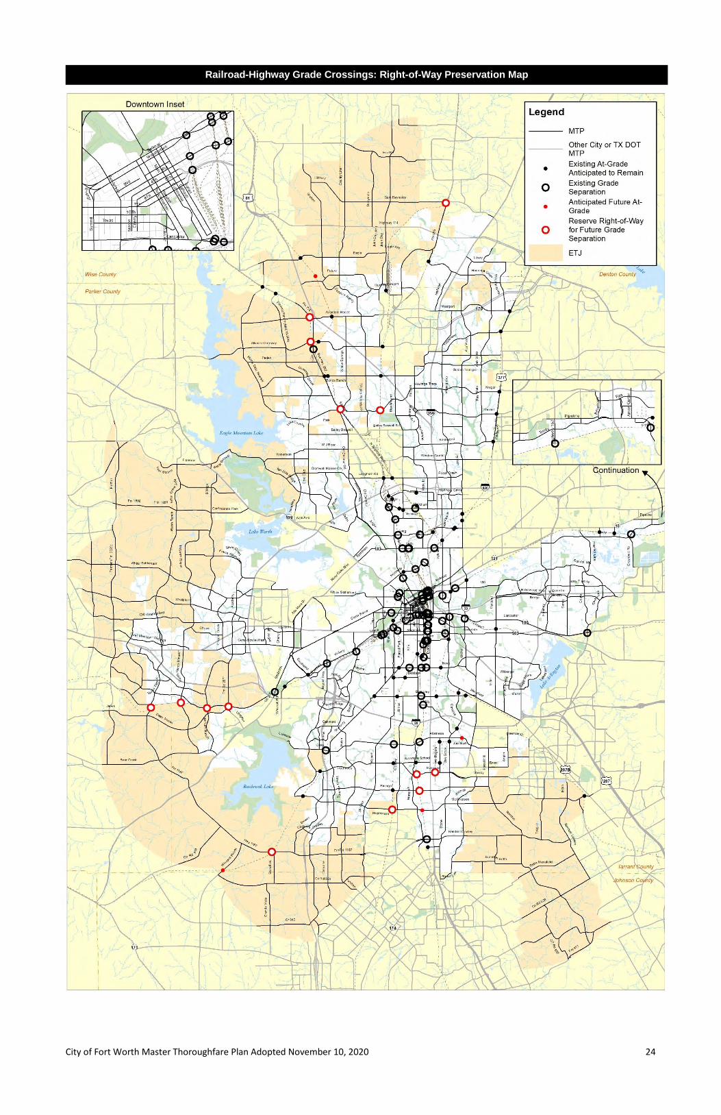
City of Fort Worth Master Thoroughfare Plan Adopted November 10, 2020 24
Railroad-Highway Grade Crossings: Right-of-Way Preservation Map

City of Fort Worth Master Thoroughfare Plan Adopted November 10, 2020 25
Established Thoroughfares As mentioned previously, Established Thoroughfares are typically not expected to increase in right-of-way or roadway width, because they are often constrained by existing development. However, positive transformations toward Complete Streets goals are nonetheless possible over time. If cross-section elements are to be modified or added, the table below indicates the minimum, maximum, and desirable widths (in feet) of these elements. Minimum widths should only be considered in constrained environments. Note that the Special Districts mentioned elsewhere may have differing ranges, and thus those standards should be consulted when appropriate. Established Thoroughfares – Width Ranges (in feet)
Auto Lanes On-Street Dedicated Bike Lanes
On-Street Transit Lanes
On-Street Parking
Non-Traversable Median
Sidewalk / Pedestrian
Zone Sidepath Separated
Bike Lane Clear + Furnishing
Zone [minus 6” curb]
Frontage Zone
Parallel Angle Standard Wide
Min Max
preferred
Min Max
preferred Min Max
preferred
Min Max
preferred Min Max
preferred Min Max
preferred Min
Max preferred
Min
Max preferred
Min Max
preferred Min Max
preferred
Min Max
preferred
Min
Max preferred
Activity Street 10 11 11 5 6 6* -11- 7.5 8 8 -19- -NA- -NA- 5 NA 6 -NA- -NA- 6.5* NA NA 7 NA 8
Commerce/Mixed-Use Street 10 11 11 5 6 6* -11- 7.5 8 8 -19- -NA- -NA- 5 NA 6 -NA- -NA- 6.5* NA NA 7 NA 8*
Neighborhood Connector -11- -6- -11- 7* -NA- 14 16 16 -NA- 6 NA 6 8 12 10 -6- 4.5 NA NA 0 NA 6 Commercial Connector 11 12 * -6- 11 12 * -NA- -NA- 14 16 16 -NA- 6 NA 6 8 12 10 -NA- 4.5 NA NA 0 NA 6 System Link 11 12 * N.A. 11 12 * -NA- -NA- 15 16 16 26 28 28 6 NA 6 8 12 10 -NA- 4.5 NA NA 0 NA 6
*The 12’
max width is only
allowed on outside
curb lanes.
*For bike lanes
adjacent to parking, add a 2’ buffer for
angle parking and a 3’ buffer for parallel parking.
*The 12’ max width
is only allowed
on outside curb
lanes.
*7’ Applies to the Special Residential
Section.
*On streets with
on-street parking, 4 feet of
the clear/ furnishing zone can be reduced
with the implementation
of curb bulb-outs / tree wells.
*If a segment can be
demonstrated to have lesser
frontage needs, a
waiver may be considered to allow a width less than the
minimum.
Often, the width available on an Established Thoroughfare will not accommodate all cross-section elements called for by the Typical Section Selection flow-chart, given the minimum widths presented above. In these cases, some elements may have to be sacrificed. Guidance on prioritizing elements is given below:
Established Thoroughfares – Section Element Width-Reduction Options (in Priority Order)
Activity Street
- Reduce flex space - Reduce parking width to 7.5’ - Reduce frontage zone (dependent on segment frontage needs) - Reduce through lanes to 10’ - Reduce bike lane width by 1 foot (5’ minimum) - Eliminate bus + parking lane; reduce to parking lane only (7.5’ minimum) - Eliminate dedicated bus lane (reduce to 8’ or 7’ buffered bike lane if bike lane warranted) - Eliminate automobile through lane on sections with two lanes in each direction
Commerce/ Mixed-Use Street
- Reduce flex space - Reduce parking width to 7.5’ - Reduce frontage zone (dependent on segment frontage needs) - Reduce through lanes to 10’ - Reduce bike lane width by 1 foot (except on section with 5’ bike lane) - Eliminate bus + parking lane; reduce to parking lane only (7.5’ minimum) - Eliminate dedicated bus lane (reduce to 6’ or 5’ bike lane if bike lane warranted and no parking; 8’ or 7’ buffered bike lane
if bike lane warranted and parking allowed) - Eliminate automobile through lane on sections with two lanes in each direction
Neighborhood Connector
- Reduce median width (14’ minimum at intersections, 6’ minimum between intersections) - Reduce flex space - Reduce separated bike lane + sidewalk – to sidepath (8’ minimum) - Reduce sidepath width (8’ minimum) - Convert sidepath to sidewalk on one side - Eliminate dedicated bus lane (reduce to 6’ bike lane if bike lane warranted) - Reduce automobile lane width to 10.5’ if surrounded by flush lanes on both sides (through lane, bike lane, or TWLTL)
Commercial Connector
- Reduce median width (14’ minimum at intersections, 6’ minimum between intersections) - Reduce flex space - Eliminate dedicated bus lane (reduce to 6’ bike lane if bike lane warranted) - Reduce automobile lane width to 10.5’ if surrounded by flush lanes on both sides (through lane, bike lane, or TWLTL)
System Link
- Reduce standard median width (14’ minimum at intersections, 6’ minimum between intersections) - Reduce wide median width (24’ minimum at intersections, 6’ minimum between intersections) - Reduce flex space - Reduce separated bike lane + sidewalk – to sidepath (8’ minimum) - Reduce sidepath width (8’ minimum) - Convert sidepath to sidewalk on one side - Eliminate dedicated bus lane
*Notes:

City of Fort Worth Master Thoroughfare Plan Adopted November 10, 2020 26
Finally, the way in which bikes are integrated within Established Thoroughfares should be determined with a focus on biker comfort and minimized stress. The Active Transportation Plan (ATP) establishes a priority order for each Street Type based on lanes, parking, and traffic volume. The table below replicates the ATP criteria, ranking which types of facilities are preferred in each situation. The operating principle is to use the highest-ranked facility type if at all possible – and if it is not, to use the “next best” facility, and so on.
Established Thoroughfares – Desirable Bike Facilities per ATP (1 = most desirable, 4 = least)
Street Type Lanes
Per Direction
Presence of Parking
Traffic Volume (ADT)
Sidepaths (BOP);
Separated Bike Lanes
(BLS)
Buffered Bike
Lanes (BLB); Botts Dots
Conventional Bike
Lanes (BLC)
Signs and Shared-Lane
Markings (BSM)
2
Yes (PP, PA) > 8,000 1 3 3 4 < 8,000 1 2 3 3
No (P0) > 8,000 1 2 3 3
< 8,000 1 2 2 3
3
NA
All Volumes 1 3 4 4
2 > 20,000 1 3 4 4
8,001-20,000 1 3 3 4 < 8,000 1 2 3 3
1
> 1500 1 2 2/3* 4
751-1500 1 2 2 3
< 750 1 2 2 2
System Link 3
NA All Volumes 1 4 4 4
2 1 3 4 4
Activity Street --OR--
Commerce/ Mixed Use Street
Neighborhood Connector
--OR--
Commercial Connector
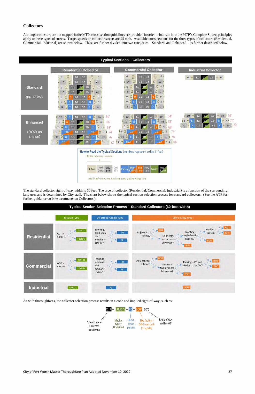
City of Fort Worth Master Thoroughfare Plan Adopted November 10, 2020 27
Collectors Although collectors are not mapped in the MTP, cross-section guidelines are provided in order to indicate how the MTP’s Complete Streets principles apply to these types of streets. Target speeds on collector streets are 25 mph. Available cross-sections for the three types of collectors (Residential, Commercial, Industrial) are shown below. These are further divided into two categories – Standard, and Enhanced – as further described below.
The standard collector right-of-way width is 60 feet. The type of collector (Residential, Commercial, Industrial) is a function of the surrounding land uses and is determined by City staff. The chart below shows the typical section selection process for standard collectors. (See the ATP for further guidance on bike treatments on Collectors.)
As with thoroughfares, the collector selection process results in a code and implied right-of-way, such as:
C_R – UNDIV – P0 – BOP (60’)
Street Type = Collector,
Residential
Median type =
Undivided
No on-street
parking
Bike facility = Off-Street path
(Sidepath)
Right-of-way width = 60’
Typical Sections – Collectors
76’ 82’
64’ 68’ 68’
76’
Standard
(60’ ROW)
Enhanced
(ROW as shown)
66’ 66’ 68’
74’ 78’
86’
66’ 74’
82’
Typical Section Selection Process – Standard Collectors (60-foot width)
How to Read the Typical Sections (numbers represent widths in feet) Widths shown are minimums
May include clear zone, furnishing zone, and/or frontage zone
Buffers Parking Auto Lane Median TWLT
/Island Bike + Parking
Curb (6”)
Ped Zone
Side-path
Bike Lane

City of Fort Worth Master Thoroughfare Plan Adopted November 10, 2020 28
In some situations, there may be a desire to upgrade a collector section to include additional section elements that may not fit in the standard 60-foot width. For example, a developer may wish to add on-street parking along a section that has a two-way left-turn lane and therefore can’t accommodate parking, or a City project may wish to include a wider sidepath on a section that provides on-street parking. In these cases, Enhanced Sections may be used. The charts below illustrate with a “●”, for each Standard Section, which Enhanced Sections (and in some cases, which Standard Sections) are available for upgrade without a waiver.
Even when an Enhanced Section is desired, the Standard Section Selection process on the previous page must first be followed to determine the appropriate Standard section, and then the Enhanced Section can be chosen from there.
Enhanced Collector Upgrade Matrices
64’ 68’ 68’ 76’ 78’ 88’
60’
60’
66’ 66’ 68’ 74’ 76’ 82’
60’
60’

City of Fort Worth Master Thoroughfare Plan Adopted November 10, 2020 29
Local Streets Local streets typically serve residential areas and are generally fronted by homes, although they can also be used in non-residential districts to provide access to commercial uses and other businesses. There are two types of local streets: • Limited Local Streets (40-foot right-of-way) serve clusters or zero-lot-line housing and carry daily traffic volumes of 1,000 vehicles or fewer.
They cannot exceed 800 feet in length or serve more than 30 dwelling units, and are limited to single-family access only. No on-street parking is allowed beyond clustered on-street areas (in which additional width is supplied for parking stalls.
• Standard Local Streets (50-foot right-of-way) are by far the more common local street configuration. These streets are designed to accommodate parking on both sides, a configuration that keeps traffic speeds low in neighborhoods.
As the section diagrams indicate, local streets are not as flexible as thoroughfares in terms of extra right-of-way for multimodal elements. They are not used as transit routes, and speeds and automobile volumes are low enough that bicycles would be expected to share the road with automobiles. On local streets in new or redeveloping mixed-use areas, the sidewalk should be placed as close to the property line as practicable to allow for landscaping, hardscaping, and lighting next to the curb – and a more comfortable pedestrian experience. Additional considerations for Local Streets in the City’s Extra-Territorial Jurisdiction (ETJ) are covered in the Fort Worth Subdivision Ordinance (see Sections 31-101(b)(2) and 31-106(c)(3)).
50’
40’ 6-inch curbs included on
both sides

City of Fort Worth Master Thoroughfare Plan Adopted November 10, 2020 30
This section covers items that are not necessarily requirements of the MTP, but are strongly related to the City’s goals for its thoroughfare system.
Intersections Intersections are key components to a successful city transportation network:
• Because intersections are the locations where opposing automobile traffic streams cross (and therefore must yield right-of-way to each other), they tend to regulate capacity of thoroughfares. Even on high-capacity thoroughfares, intersections can act as capacity bottlenecks if not properly designed.
• Intersections are also the locations where pedestrians most frequently cross city streets. Thus, they need to be designed to allow these movements to be made safely and efficiently.
These two facts are often in tension; focusing on automobile capacity tends to favor larger intersections (largely as a result of turn lanes), while focusing on pedestrian elements tends to favor smaller intersections (with minimized crossing distances). Out of this tension arises the need for thoughtful, careful planning and design of intersections to optimize capacity and safety for all users. This philosophy is in harmony with the overall philosophy of the MTP. Intersection design elements that can help to achieve these objectives include the following:
• Right-turn channelization and median nose cut-throughs, which can minimize pedestrian crossing exposure.
• Minimized curb radii, which can reduce right-turn speeds and also shorten pedestrian crossing distances.
• Narrowed lanes to reduce vehicle speeds and pedestrian crossing distances.
• Use of roundabouts to slow speeds, optimize efficiency, and minimize pedestrian crossing exposure.
• High-visibility crosswalk markings or other crossing treatments such as raised crosswalks (even across channelized right-turn lanes).
• Accessibility and universal design principles.
• Special pedestrian/bicyclist signalization considerations (pedestrian countdown signals, Leading Pedestrian Intervals, exclusive pedestrian signal phases, and bicycle detection/marking).
The MTP does not address intersection right-of-way, planning, or design in detail (neither the items above nor such design considerations as turn lanes); these items are included in the standards and guidelines of T/PW. As future portions of the MTP network build out, right-of-way needs at intersections should be carefully considered. See the Access Management Policy and Transportation Engineering Manual for more information. Micromobility Micromobility is a category of transportation modes featuring very light, typically motorized vehicles such as electric scooters, electric skateboards, shared bicycles and electric pedal-assisted bicycles. The City does not allow operation of shared micromobility systems to conduct commercial activity in the right-of-way without specific authorization. However, personal private micromobility vehicles, such as electric scooters, are not prohibited from operating on the City’s transportation system. The City’s preference is for these vehicles to operate in the areas designated for bicycles (whether on-street or off-street, depending on the street cross-section). Micromobility parking typically affects the parkway portion of the cross-section. It is imperative that parked micromobility vehicles not block pedestrian/ADA/bicycle paths or access to local businesses. The best places to park these vehicles off-street are the buffers nearest the street – especially the furnishing zone. The MTP does not guide the specific placement of street furniture, but in the case of micromobility parking (in areas where appropriate based on demand), planners and designers are encouraged to consider designating areas for this activity. Micromobility corrals (often interspersed with on-street automobile parking) are one solution that promotes organized, compact, aggregated storage of these vehicles.
Related Topics VII

City of Fort Worth Master Thoroughfare Plan Adopted November 10, 2020 31
Railroad Quiet Zones A Quiet Zone is an at-grade highway/railroad crossing at which trains are prohibited from routinely sounding their horns in order to decrease the noise level for nearby residential communities. The train horns can be silenced only when other safety measures compensate for the absence of the horns. A Quiet Zone must comply with City and Federal Railroad Administration (FRA) regulations and must be coordinated with the City. Some of the methods of implementing Quiet Zones are: Crossing elimination, median barrier, wayside horn system, four-quadrant gate system, and other measures. Refer to City’s Quiet Zone Establishment Process for guidance on how to request the establishment of a Quiet Zone and the timeline/milestones involved. The graphic below illustrates some typical design parameters for a Quiet Zone in Fort Worth using a median barrier. Other considerations to be aware of include the following:
• One set of flashing lights is required per lane. In the design below, the median on the right is wide enough to accommodate a set of flashing lights. If only a narrower median can be provided (e.g., the median on the left), cantilevers must be installed to provide the required set of flashing lights over each lane of traffic. The railroad gate arms are spring-loaded to assist in preventing gates from breaking when struck by vehicles.
• All proposed construction near an existing Quiet Zone must be reviewed by the TPW Quiet Zone project manager to verify that the proposed construction does not violate the Quiet Zone rule and thereby invalidate the Quiet Zone.
• All existing or planned vegetation and signing on the approaches to highway-rail grade crossings must be maintained in a manner that allows the railroad flashing lights and signs to be completely visible to drivers approaching the crossing.
• A signalized intersection within 200 feet of a highway-rail grade crossing must be interconnected with the railroad warning devices to provide preemption capabilities. In addition, any signalized intersection over 200 feet away that is known to have traffic queuing onto the crossing must be evaluated by a diagnostic team to determine if interconnection is required.
• The speed limit of the roadway must be 40 mph or less.
10’
100’ min. may be reduced to 60’ if no intersecting
driveways or streets within 100’; no tapering allowed in this distance
6’ Cantilevers are
installed 6’ in front of gate assembly
See Table A
60’ no commercial driveways
or side streets
If median is less than 10’ wide, railroad flashers (one per lane) to be mounted on
cantilever assembly
<10’
Coordinate ped crossing panel construction with
railroad
Railroad crossing signal and gate assembly
2’ asphalt section at edge of railroad
crossing surface
5’ min. distance between center of gate assembly foundation and sidewalk
10’ min. (8” tall) to accommodate additional RR flasher; may be reduced to 9’ with RR approval
Note: MUTCD guidance on signage and pavement markings
for quiet zone and railroad crossings not shown
Square off median parallel to track
Typical Quiet Zone Design Parameters (with median barrier)
15’ from
centerline of nearest track
Table A
UP, BNSF & Others FWRR
With shoulder curb 5’3” 4’6”
Without shoulder curb 9’3” 8’3”

City of Fort Worth Master Thoroughfare Plan Adopted November 10, 2020 32
Access Management The City’s Adopted Access Management Policy defines access management as “the coordinated planning, regulation, and design of access between roadways and land development.” Underlying this definition is the acknowledgement that poorly designed access systems can significantly impact the operation, safety and flow of traffic on the roadway network. This in turn can negatively affect property access, public perceptions, and community character. Inadequate access systems can also require expensive remedial measures. Conversely, good access management can promote safe and efficient traffic flow, facilitate orderly property access, protect the substantial public investment in the street system, and benefit the community at large. The purpose, therefore, of Fort Worth’s Access Management Policy is to provide for and manage access to land development, while preserving the regional flow of traffic in terms of safety, capacity, and speed. The Policy recognizes both the right of reasonable access to private property and the right of transportation users in Fort Worth to safe and efficient travel. The Policy provides recommendations based on Street Type, as appropriate. Therefore, while the MTP does not directly address intersection and driveway spacing, its street classifications are used as the basis for the City’s policies in this area. Complete Streets Landscaping Elements The MTP does not require landscaping as a part of its cross-sections (with the exception of certain Special Districts mentioned elsewhere), but the cross-sections are designed to accommodate landscaping – and function optimally when proper vertical landscaping elements are introduced near the travel way. The City’s subdivision ordinances include requirements to include street trees at 50-foot spacing within arterial parkways that back up to residential fences. It is highly encouraged that such trees be placed in the furnishing zone (between the curb and any pedestrian or bicycle facility). Street trees are encouraged in the parkway areas of all thoroughfares, and in raised medians as well. These items are critical to calming traffic on arterial streets, and should be incorporated into all thoroughfare designs. The placement of trees and shrubs can have traffic calming effects. When trees of a caliper considered non-frangible (six inches or more) are placed in medians, it is best to have at least an eight-foot median, with trees set back from edges four feet; this means that all MTP medians except the narrow median are candidates for tress of this size. Trees not expected to have calipers of six inches or greater can be placed closer to median edges, and thus can be included in narrow medians as well. Trees are often set back 100 feet from intersections (based on speed) for safety and sight-distance reasons. Additional (non-traffic) benefits of a tree canopy along a thoroughfare right-of-way include (1) cooler temperatures at street level helping to preserve pavement life, (2) rainwater capture – by both tree canopy and root systems – potentially helping reduce flooding when storm drains are already near peak capacity, (3) more efficient absorption of emissions (and conversion to oxygen) than trees planted away from thoroughfares, and (4) potential economic benefits from increasing the street’s attractiveness as a gathering place. Pedestrian-scale lighting is also an element of the streetscape that can contribute to a vibrant, safe, attractive environment for pedestrians. As thoroughfares are built, lighting and landscaping should be considered to the extent that they meet the City’s goals for its streets and its overall aesthetic civic appeal. Traffic Impact Analyses Proposed development or redevelopment in Fort Worth must generally be supported by traffic impact studies that examine the effects of the development on all relevant modes of transportation and the surrounding transportation network. As alluded to in Section I, larger development projects, especially those involving rezoning actions, could trigger a need to modify the alignment of a thoroughfare, its designation on the Street Type map, or its capacity on the Lanes Map. The City’s Traffic Impact Analysis (TIA) Guidelines, contained in its Transportation Engineering Manual, prescribe the methods to analyze and address these effects, and also to examine the smaller-scale impacts of development, such as nearby intersection capacity, connectivity of automobile and Active Transportation facilities, and transportation safety. TIAs enact at a local scale the principles that the MTP sets forth at a citywide scale. Green Infrastructure (GI) The EPA defines GI as “an adaptable term used to describe an array of products, technologies, and practices that use natural systems - or engineered systems that mimic natural processes - to enhance overall environmental quality and provide utility services. As a general principle, Green Infrastructure techniques use soils and vegetation to infiltrate, evapotranspirate, and/or recycle stormwater runoff.” GI applies to many aspects of development beyond just transportation, but the transportation system can play a role in the implementation of GI principles by incorporating stormwater controls and managing development-related runoff. The City of Fort Worth and the North Central Texas region are supportive of the GI approach. Although the City does not have an official policy regarding the incorporation of GI principles into thoroughfares, many (if not most) of the MTP typical sections could accommodate a GI application if deemed appropriate. Some of the most common GI treatments in street rights-of-way include landscape treatments, or the use of landscape areas to temporarily store water: bioretention, rain gardens, bioswales, tree wells, planter boxes, and infiltration trenches. Plant selection is critical to the success of any such installation: plants must be hardy, must deal with stormwater appropriately, and should be aesthetically appealing. Examples of these types of treatments are shown below:
In the median In bulbouts or tree-wells Within the street side of the parkway Within the back side of the parkway (or in private right-of-way)
City of Fort Worth Master Thoroughfare Plan Adopted November 10, 2020 33
By their nature, some of these treatments may be only applicable to specific MTP Street Types or cross-sections. For example, a median treatment would not be applicable on a Commerce/Mixed-Use Street, which has no median sections. Curb bulbouts and/or tree-wells would only be applicable on sections providing on-street parking. Thus, the context-sensitive philosophy of the MTP would extend to the application of GI treatments. One other class of GI treatment applicable to the MTP includes permeable pavement and porous concrete. While these are not considered acceptable for use within the roadway (between the curbs), they do have potential application within the parkway (behind the curbs) as materials for sidewalks, sidepaths, and separated bike lanes. Any GI installation must be accompanied by a long-term operations and maintenance plan, including an agreement as to maintenance responsibility, to ensure it functions as intended for its intended lifespan. Without proper maintenance, plant-based GI treatments especially can quickly fail. For more information on transportation-related GI treatments, see NCTCOG’s Transportation integrated Stormwater Management (TriSWM) Appendix of the integrated Stormwater Management (iSWM) Criteria Manual for Site Development and Construction.
Other Relevant Documents and Regulations The MTP is integrally tied to several other documents and regulations of which the reader should be aware. Many of these have been listed elsewhere in the MTP, but they are collected here for convenience. • The Fort Worth Comprehensive Plan guides long-term decisions about growth and development. Many aspects of this document – its aspirations
of how the City wants to evolve – are germane to the MTP. In particular, the Future Land-Use Map sets the primary context in which MTP Street Types should be evaluated.
• The Fort Worth Subdivision Ordinance (Chapter 31 of the Fort Worth Code of Ordinances) guides the land development process – in a sense, it is an implementation document for the Comprehensive Plan – and links approval of development plans to, among other things, conformity with the MTP. It also addresses related aspects of implementation such as landscape requirements along arterials and collector network planning.
• The City’s Access Management Policy provides requirements on access location/design as well as network planning – tied to the Street Types
that are integral to the MTP.
• The City’s Complete Streets Policy provides additional guidance to both staff and the community for street planning/design consistent with the principles of the MTP to provide a safe, accessible, complete, connected, comfortable, efficient, and community-oriented transportation system for all people that supports mobility options, healthy living and economic benefit.
• The City’s Transportation Engineering Manual defines the City’s design requirements for transportation infrastructure. Many of the Manual’s
requirements are tied to Street Type as defined by the MTP. The Manual covers topics including Street Design, Bicycle Facilities, Pedestrian Zones, Intersection Design, Mid-Block Crossings, Access Control, Off-Street Parking, and Transit Accommodation. The Manual is also the home of the City’s Traffic Impact Analysis Guidelines, which provide guidance on the scope, scale, criteria and procedures for analyzing the transportation effects of development or redevelopment.
• Trinity Metro’s Transit Master Plan is the community’s vision for transit. It identifies Frequent Service routes that could be candidates for
Special Transit Lanes within the MTP. Since the MTP includes Special Transit Lanes in each of its Street Types, the City and Trinity Metro can work to identify the most sensible thoroughfare segments for these lanes going forward. At the time of this writing, the document is being updated as Transit Moves Fort Worth.
• The Fort Worth Active Transportation Plan (ATP) provides a shared vision for active transportation priorities and a comprehensive framework for implementation. It identifies the priority infrastructure network for citywide and regional active transportation travel. It also includes policy recommendations, performance measures to guide investments and accountability, and prioritized project lists with cost opinions. The ATP is designed to dovetail with the MTP. The ATP’s Bicycle Network is incorporated into the MTP’s typical section selection process, and its principles for incorporating bicycle infrastructure into Established Thoroughfares are re-presented in the MTP.
• The Parks, Recreation and Open Space Master Plan guides the management and development of the City’s parkland and recreational facilities.
Parks are shown on the MTP maps because park-adjacent arterials may need special treatments, and because connectivity to parks is vital. Thus, there is a strong link between the Parks plan and the MTP.
• NCTCOG’s integrated Stormwater Management (iSWM) Criteria Manual for Site Development and Construction, a product of regional efforts,
contains criteria that cities and counties may use as a component of their stormwater management related development regulations. In particular, the Transportation appendix (known as TriSWM) provides information on Green Infrastructure improvements relevant to transportation facilities.
• As mentioned in Section III, there are three Special Districts whose transportation plans and standards supersede the MTP. The relevant
documents are:
- Trinity Lakes Development Code - Panther Island Form Based Zoning District: Zoning Standards and Guidelines - Stockyards Historic and Form-Based Code District
Several other districts are located within established areas, and if changes are to be proposed on Established Thoroughfares within these districts, their guiding documents should be referred to:
- Downtown Urban Design Standards and Guidelines - Near Southside Standards and Guidelines - Berry/University Form-Based Code
• County Plans: When planning transportation infrastructure in the ETJ, the City and/or applicants must coordinate with the applicable County.

Appendix A: Assigned Cross-Section List


