CITY OF FRIENDSWOOD TECHNICAL SPECIFICATIONS MORTAR 03100-1 City of Friendswood Revised: 7/10/2008 SECTION 03100 MORTAR PART I: GENERAL 1.1 GENERAL REQUIREMENTS A. Mortar and grout for masonry. 1.2 MEASUREMENT AND PAYMENT A. Unit Prices: 1. No separate payment shall be made for mortar for facilities under this Section. Include payment in Lump Sum for building or structure with price breakdown included in Schedule of Values. 2. No separate payment shall be made for mortar utilities under this Section. Include payment in unit price for the utility work. 3. Refer to Section 01270 – Measurement and Payment and Section 01295 – Schedule of Values. B. Stipulated Price (Lump Sum). If Contract is Stipulated Price Contract, payment for work in this Section is included in Total Stipulated Price. 1.3 REFERENCES A. ASTM – American Society for Testing and Material. 1. ASTM C109 – Standard Test Method for Compressive Strength of Hydraulic Cement Mortars. 2. ASTM C143 – Standard Testing Method for Slump of Hydraulic Cement Concrete 3. ASTM C144 – Standard Specification for Aggregate for Masonry Mortar. 4. ASTM C150 – Standard Specification for Portland Cement. 5. ASTM C207 – Standard Specification for Hydrated Lime for Masonry Purposes.
Transcript
CITY OF FRIENDSWOOD TECHNICAL SPECIFICATIONS MORTAR
03100-1 City of Friendswood Revised: 7/10/2008
SECTION 03100
MORTAR
PART I: GENERAL
1.1 GENERAL REQUIREMENTS
A. Mortar and grout for masonry.
1.2 MEASUREMENT AND PAYMENT
A. Unit Prices:
1. No separate payment shall be made for mortar for facilities under this Section. Include payment in Lump Sum for building or structure with price breakdown included in Schedule of Values.
2. No separate payment shall be made for mortar utilities under
this Section. Include payment in unit price for the utility work. 3. Refer to Section 01270 – Measurement and Payment and
Section 01295 – Schedule of Values.
B. Stipulated Price (Lump Sum). If Contract is Stipulated Price Contract, payment for work in this Section is included in Total Stipulated Price.
1.3 REFERENCES
A. ASTM – American Society for Testing and Material.
1. ASTM C109 – Standard Test Method for Compressive Strength of Hydraulic Cement Mortars.
2. ASTM C143 – Standard Testing Method for Slump of Hydraulic
Cement Concrete 3. ASTM C144 – Standard Specification for Aggregate for
Masonry Mortar. 4. ASTM C150 – Standard Specification for Portland Cement. 5. ASTM C207 – Standard Specification for Hydrated Lime for
Masonry Purposes.
CITY OF FRIENDSWOOD TECHNICAL SPECIFICATIONS MORTAR
03100-2 City of Friendswood Revised: 7/10/2008
6. ASTM C270 – Standard Specification for Mortar for Unit
Masonry. 7. ASTM C404 – Standard Specification for Aggregates for
Masonry Grout. 8. ASTM C476 – Standard Specification for Grout for Masonry. 9. ASTM C780 – Standard Test Method for Preconstruction and
Construction Evaluation of Mortars for Plain and Reinforced Unit Masonry.
B. CFTS – City of Friendswood Technical Specifications.
A. Conform to requirements of Section 01330 – Submittal Procedures. B. Include design mix, indicate Property Method used, required
environmental conditions, and admixture limitations. C. Samples: Submit two (2) ribbons of each mortar color, illustrating color
and color range. D. Submit test reports under provisions of Section 01450 – Contractor's
Quality Control. E. Submit test reports on mortar indicating conformance to ASTM C270. F. Submit test reports on grout indicating conformance to ASTM C476.
CITY OF FRIENDSWOOD TECHNICAL SPECIFICATIONS MORTAR
03100-3 City of Friendswood Revised: 7/10/2008
G. Submit manufacturer's certificate under provisions of Section 01450 – Contractor's Quality Control, that products meet or exceed specified requirements.
1.5 DELIVERY, STORAGE, AND HANDLING
A. Deliver products to site and store and protect products under provisions of Section 01610 – Approved Products List.
B. Maintain packaged materials clean, dry, and protected against
dampness, freezing, and foreign matter.
1.6 ENVIRONMENTAL REQUIREMENTS
A. Maintain materials and surrounding air temperatures to a minimum fifty degrees Fahrenheit (50° F) prior to, during, and forty-eight hours (48 Hrs) after completion of masonry work.
1.7 MIX TESTS
A. Test mortar and grout in accordance with Sections 01470 – Testing Laboratory Services and 01475 – Quality Control Testing Procedures.
B. Testing of Mortar Mix: Test in accordance with ASTM C780. Test
mortar mix for compressive strength, consistency, mortar aggregate ratio, water content, air content, and splitting tensile strength.
C. Testing of Grout Mix: Test in accordance with ASTM C109. Test grout
mix for compressive strength and slump.
PART II: PRODUCTS
2.1 MATERIALS
A. Portland Cement: ASTM C150, Type I, white color. B. Masonry Cement: Not permitted. C. Mortar Aggregate: ASTM C144, standard masonry type. Grading and
color suitable for type of masonry, one (1) source for entire project. [Not less than five percent (5%) shall pass No. 100 sieve].
D. Hydrated Lime: ASTM C207, Type S. E. Grout Aggregate: ASTM C404.
CITY OF FRIENDSWOOD TECHNICAL SPECIFICATIONS MORTAR
03100-4 City of Friendswood Revised: 7/10/2008
F. Water: Clean and potable.
2.2 MORTAR COLOR
A. Mortar Color: Mineral oxide pigment; color; to be selected by the Project Manager from manufacturer's samples.
2.3 ADMIXTURES
A. Antifreeze: Antifreeze admixtures shall not be permitted. B. Accelerator: Accelerator may be used only with approval of the Project
Manager.
2.4 MORTAR
A. Mortar for Load Bearing Walls and Partitions: ASTM C270, Type S utilizing Property Method to achieve one thousand eight hundred pounds per square inch (1800 psi) strength.
B. Mortar for Non-load Bearing Walls and Partitions: ASTM C270, Type S
utilizing the Property Method to achieve one thousand eight hundred pounds per square inch (1800 psi) strength.
C. Mortar for Masonry Below Grade or in Contact with Earth: ASTM C270,
Type M utilizing the Property Method to achieve two thousand five hundred pounds per square inch (2500 psi) strength.
D. Pointing Mortar: ASTM C270, Type N, using the Property Method to
achieve seven hundred fifty pounds per square inch (750 psi) strength.
2.5 MORTAR MIXING
A. Thoroughly mix mortar ingredients in quantities needed for immediate use in accordance with ASTM C270 to achieve strengths noted in Paragraph 2.4.
B. Add mortar color and admixtures in accordance with manufacturer's
instructions. Provide uniformity of mix and coloration. C. Do not use anti-freeze compounds to lower freezing point of mortar. D. If water is lost by evaporation, retemper only within two hours (2 Hrs) of
mixing. E. Use mortar within two hours (2 Hrs) after mixing at temperatures of
CITY OF FRIENDSWOOD TECHNICAL SPECIFICATIONS MORTAR
03100-5 City of Friendswood Revised: 7/10/2008
eighty degrees Fahrenheit (80° F), or two and one-half hours (2-1/2 Hrs) at temperatures under fifty degrees Fahrenheit (50° F).
2.6 GROUT
A. Bond Beams, Lintels, and Other Areas to be Grouted Solid: Three thousand pounds per square inch (3000 psi) strength at twenty-eight days (28 D); seven inch (7 In) to eight inch (8 In) slump per ASTM C143; mixed in accordance with ASTM C476, Fine Grout.
2.7 GROUT MIXING
A. Thoroughly mix mortar ingredients in quantities needed for immediate use in accordance with ASTM C476, Fine Grout.
B. Add admixtures in accordance with manufacturer's instructions.
Provide uniformity of mix. C. Do not use anti-freeze compounds to lower freezing point of grout.
PART III: EXECUTION
3.1 EXAMINATION
A. Request inspection of spaces to be grouted.
3.2 PREPARATION
A. Apply bonding agent to existing concrete surfaces. B. Plug clean out holes with masonry units to prevent leakage of grout
materials. Brace masonry for wet grout pressure.
3.3 INSTALLATION
A. Install mortar and grout in accordance with manufacturer's instructions. B. Work grout into masonry cores and cavities to eliminate voids. C. Do not displace reinforcement while placing grout. D. Remove grout spaces of excess mortar.
END OF SECTION
CITY OF FRIENDSWOOD TECHNICAL SPECIFICATIONS GROUT
03105-1 City of Friendswood Revised: 7/10/2008
SECTION 03105
GROUT
PART I: GENERAL
1.1 GENERAL REQUIREMENTS
A. Mix design requirements, testing, furnishing and production of grout for:
1. Pressure grouting of jacked-pipe. 2. Annular grouting of cased or uncased sewer pipe. 3. Grouting voids in ground resulting from caving, loss of ground
or settlement.
B. Compaction grouting is not part of this specification.
1.2 MEASUREMENT AND PAYMENT
A. Unit Prices:
1. No separate payment shall be made for the Work performed under this Section. Include cost of such the Work in contract unit prices for the Work of which it is component part.
2. Refer to Section 01270 - Measurement and Payment for Unit
Price procedures.
B. Stipulated Price (Lump Sum): 1. If Contract is Stipulated Price Contract, payment for the Work in
this Section is included in Total Stipulated Price.
1.3 DEFINITIONS
A. Pressure Grouting: Filling void behind liner or pipe with grout under pressure sufficient to ensure void is properly filled but without overstressing temporary or permanent ground support or causing ground heave to occur.
B. Annular Grouting: Filling annular space between carrier pipe and
casing or ground, by pumping.
CITY OF FRIENDSWOOD TECHNICAL SPECIFICATIONS GROUT
03105-2 City of Friendswood Revised: 7/10/2008
C. Ground Stabilization Grouting: Filling of voids, fissures or under-slab
settlement due to caving or loss of ground by injecting grout under gravity or pressure to fill void.
1.4 REFERENCE STANDARDS
A. ASTM – American Society for Testing and Materials.
1. ASTM C138 Standard Test Method for Unit Weight, Yield and Air Content (Gravimetric) of Concrete.
2. ASTM C144 Standard Specification for Aggregate for Masonry
Mortar. 3. ASTM C150 Standard Specification for Portland Cement. 4. ASTM C494 Standard Specification for Chemical Admixture for
Concrete. 5. ASTM C869 Standard Specification for Foaming Agents Used
in Making Preformed Foam for Cellular Concrete. 6. ASTM C937 Standard Specification for Grout Fluidifier for Pre-
placed Aggregate Concrete. 7. ASTM C942 Standard Test Method for Compressive Strength
of Grout for Pre-placed Aggregate Concrete into Laboratory. 8. ASTM C1017 Standard Specification for Chemical Admixture
for Use in Producing Flowing Concrete.
B. CFTS – City of Friendswood Technical Specifications.
CITY OF FRIENDSWOOD TECHNICAL SPECIFICATIONS GROUT
03105-3 City of Friendswood Revised: 7/10/2008
1.5 SUBMITTALS
A. Conform to requirements of Section 01330 - Submittal Procedures. B. Submit description of materials, grout mix, equipment and operational
procedures to accomplish each grouting operation. Description may include sketches as appropriate, indicating type and location of mixing equipment, pumps, injection points, venting method, flow lines, pressure measurement, volume measurement, grouting sequence, schedule and stage volumes. Tests and certifications shall have been performed within last twelve months (12 Mos) prior to date of submittal.
C. Submit grout mix design report, including:
1. Grout type and designation. 2. Grout mix constituents and proportions, including materials by
weight and volume. 3. Grout densities and viscosities, including wet density at point of
placement. 4. Initial set time of grout. 5. Bleeding, shrinkage/expansion. 6. Compressive strength.
D. For cellular grout, also submit the following:
1. Foam concentrate supplier's certification of dilution ratio for foam concentrate.
2. A description of proposed cellular grout production procedures.
E. Maintain and submit logs of grouting operations indicating pressure, density and volume for each grout placement.
PART II: PRODUCTS
2.1 MATERIALS
A. Grouting materials: Conform to Section 03300 – Structural Concrete, except as modified in the following paragraphs.
CITY OF FRIENDSWOOD TECHNICAL SPECIFICATIONS GROUT
03105-4 City of Friendswood Revised: 7/10/2008
B. Grout Type Applications.
1. Grout for pressure grouting, backfill grouting and annular grouting: Sand-cement mortar mix.
2. Grout for annular grouting of sanitary sewer: Low density
(cellular) grout, unless otherwise approved by the Project Manager.
3. Grout for filling space in manholes: Sand-cement mortar mix. 4. Ground stabilization: Sand-cement mortar mix.
C. Do not include toxic or poisonous substances in grout mix or otherwise inject such substances underground.
2.2 GROUT
A. Develop one (1) or more mixes based on following criteria as applicable:
1. Size of annular void between sewer pipe and casing or size of
void between casing and surrounding soil. 2. Absence or presence of groundwater. 3. Adequate retardation. 4. Non-shrink characteristics. 5. Pumping distances.
B. Prepare mixes that satisfy required application. Provide materials conforming to the following standards:
CITY OF FRIENDSWOOD TECHNICAL SPECIFICATIONS GROUT
03105-5 City of Friendswood Revised: 7/10/2008
C. Provide grout meeting the following minimum requirements:
1. Minimum twenty-eight day (28 D) unconfined compressive
strength: one thousand five hundred pounds per square inch (1500 psi) for water lines, one thousand pounds per square inch (1000 psi) for other carrier pipes for mortar grout and three hundred pounds per square inch (300 psi) for cellular grout.
2. Determine strength by ASTM C942. 3. Maximum allowable density: Less than one hundred thirty
pounds per cubic foot (130 pcf).
D. Fluidifier: Provide fluidifier, meeting ASTM C937 that holds solid constituents of grout in colloidal suspension and is compatible with cement and water used in grouting operations.
E. Admixtures.
1. Use admixtures meeting ASTM C494 and ASTM C1017 as required, to improve pump ability, control time of set, hold sand in suspension and reduce segregation and bleeding.
2. For cellular grout, do not use foam or admixtures that promote
steel corrosion. 3. Ensure that admixtures used in mix are compatible. Provide
written confirmation from admixture manufacturers of their compatibility.
PART III: EXECUTION
3.1 PREPARATION
A. Notify the Project Manager at least twenty-four hours (24 Hrs) in advance of grouting operations.
B. Select and operate grouting equipment to avoid damage to new or
existing underground utilities and structures. C. In selection of grouting placement consider pipe flotation, length of pipe,
length of tunnel, depth from surface and type of sewer pipe, type of pipe blocking and bulkheading, grout volume and length of pipe to be grouted between bulkheads.
CITY OF FRIENDSWOOD TECHNICAL SPECIFICATIONS GROUT
03105-6 City of Friendswood Revised: 7/10/2008
D. Operate dewatering systems until grouting operations are complete and
grout has reached initial set.
3.2 EQUIPMENT
A. Batch and mix grout in equipment of sufficient size and capacity to provide necessary quality and quantity of grout for each placement stage.
B. Use equipment for grouting of type and size generally used for the
Work, capable of mixing grout to homogeneous consistency and providing means of accurately measuring grout component quantities and accurately measuring pumping pressures. Use pressure grout equipment which delivers grout to injection point at steady pressure.
3.3 ANNULAR GROUTING FOR SEWER/WATER LINE IN CASED OR
UNCASED AUGERS
A. Fill annular space between sewer pipe and casing or ground, with grout.
B. Placement:
1. Placement Limits: Predetermine limits of each grout placement stage by size and capacity of batching equipment and initial set time of proposed grout. Under no circumstances shall placement continue at grout port longer than that period of time for mix to take initial set. Locate grout hole spacing and locations according to number of stages necessary to grout tunnel liners. Stage or lift cannot be installed on another lift until proper set has been attained. Have placement procedures approved by admixture or additive manufacturer.
2. Limit pressure on annular space to prevent damage or
distortion to pipe. Define limiting and estimated required pressure range. Provide an open ended, high point tap or equivalent vent and monitor it at bulkhead opposite to point of grouting.
3. Pump grout until material discharging is similar in consistency
to that at point of injection.
C. Remove temporary bulkheads installed for grouting. D. Batch and mix cellular grout mechanically to ensure consistency of mix.
CITY OF FRIENDSWOOD TECHNICAL SPECIFICATIONS GROUT
03105-7 City of Friendswood Revised: 7/10/2008
Wet solids thoroughly before introduction of foaming agent. Operate batching system to maintain slurry weight within three percent (3%) of design density. Introduce foam into slurry in accordance with manufacturer's recommendations.
3.4 PRESSURE GROUTING FOR JACKED PIPE
A. For jacked pipe sixty inches (60 In) in diameter or greater, pressure grout annulus after installation, displacing bentonite lubrication. Jacked pipes less than sixty inch (60 In) diameter may be left ungrouted unless excavated diameter exceeds external pipe diameter by more than one inch (1 In).
B. Inject grout through grout holes in sewer pipe. Drilling holes from
surface or through carrier pipe walls is not allowed. Perform grouting by injecting it at pipe invert with bentonite displacement occurring through high point tap or vent.
C. Control ground water as necessary to permit completion of grouting
without separation of grout materials. D. Limit pressures to prevent damage or distortion to pipe or to keep
flexible pipe within acceptable tolerances. E. Pump grout until material discharging is similar in consistency to that at
point of injection.
3.5 GROUND STABILIZATION GROUTING
A. Completely fill voids outside limits of excavation caused by caving or collapse of ground. Fill with gravity or pressure injected sand-cement grout as necessary to fill void.
B. Take care in grouting operations to prevent damage to adjacent utilities
or public or private property. Grout at pressure that shall not distort or imperil portion of the Work or existing installations or structures.
C. Verify that void has been filled by volumetric comparisons and visual
inspection. In case of settlement under existing slabs, take cores as directed by the Project Manager, at no additional cost to the City, to demonstrate that void has been filled.
3.6 FIELD QUALITY CONTROL
A. Annular Grouting for Sewer Line in Cased or Uncased Augers.
CITY OF FRIENDSWOOD TECHNICAL SPECIFICATIONS GROUT
03105-8 City of Friendswood Revised: 7/10/2008
1. Make one (1) set of four (4) compressive test specimens for every two hundred feet (200 Ft) of sewer pipe installed in primary lined tunnel.
2. For cased or uncased augers, make one (1) set of four (4)
compressive test specimens for each grouting operation or for each one hundred feet (100 Ft) of pipe installed, whichever is more frequent.
3. For cellular grout, check slurry density both at point of batching
and placement at least twice each hour in accordance with ASTM C138. Record density, time and temperature. Density must be within three percent (3%) of design density at point of batching and five percent (5%) of design density at point of placement.
B. Pressure Grouting for Jacked Pipe. Make one (1) set of four (4)
compressive test specimens for every four hundred feet (400 Ft) of jacked pipe pressure grouting.
C. Ground Stabilization Grouting. Make one (1) set of four (4)
compressive test specimens for every location where ground stabilization grouting is performed.
D. All testing to be done in conformance with Section 01470 – Testing
Laboratory Services and Section 01475 – Quality Control Testing Procedures.
END OF SECTION
CITY OF FRIENDSWOOD REINFORCING TECHNICAL SPECIFICATIONS STEEL
03200-1 City of Friendswood Revised: 7/10/2008
SECTION 03200
REINFORCING STEEL
PART I: GENERAL
1.1 GENERAL REQUIREMENTS
A. Furnishing, fabrication and installation of all reinforcing bar, and for placement in concrete.
B. Requirements for placing, tying and supporting reinforcing steel in
concrete.
1.2 MEASUREMENT AND PAYMENT
A. UNIT PRICES:
1. No separate payment shall be made for reinforcing steel used as part of a new cast-in-place structure or concrete paving. Include cost for labor, materials and equipment in the cost of the bid item for the structure or paving.
2. Refer to Section 01270 – Measurement and Payment for unit
price procedures.
B. Stipulated Price (Lump Sum):
1. If Contract is Stipulated Price Contract, payment for work in this Section is included in Total Stipulated Price.
1.3 REFERENCES
A. ACI – American Concrete Institute.
1. ACI 3 1813 18R – Building Code Requirements for Reinforced Concrete and Commentary.
1. Placing Reinforcing Bars. 2. Manual of Standard Practice.
F. ICBO – International Conference of Building Officials.
1. ICBO Research Report.
G. WRI – Wire Reinforcement Institute.
1. Manual of Standard Practice, Welded Wire Reinforcement.
CITY OF FRIENDSWOOD REINFORCING TECHNICAL SPECIFICATIONS STEEL
03200-3 City of Friendswood Revised: 7/10/2008
1.4 SUBMITTALS
A. Conform to requirements of Section 01330 – Submittal Procedures. B. Action Submittals:
1. Shop Drawings prepared in accordance with CRSI Manual of Standard Practice and ACI SP-66 Detailing Manual:
a. Bending lists. b. Placing drawings.
C. Informational Submittals:
1. Lab test reports for reinforcing steel showing stress-strain curves and ultimate strengths.
2. Mechanical Threaded Connections:
a. Current International Conference of Building Officials (ICBO) Research Report or equivalent code agency report listing findings to include acceptance, special inspection requirements, and restrictions.
b. Manufacturer's instructions. c. Verification that device threads have been tested and
meet requirements for thread quality, in accordance with manufacturers published methods.
D. Welding Qualification: Prior to welding, submit welder qualifications
and nondestructive testing procedures. E. Test results of field testing. F. Shop drawings shall show all bars, sizes, dimensions, spacings,
clearances, and placement patterns.
1.5 QUALITY ASSURANCE
A. Provide manufacturer's affidavits that steel was manufactured in compliance with standards referenced in this Section.
B. Provide manufacturer's affidavits that steel is American made and not
imported.
CITY OF FRIENDSWOOD REINFORCING TECHNICAL SPECIFICATIONS STEEL
03200-4 City of Friendswood Revised: 7/10/2008
C. Welder Qualifications: Certified in accordance with AWS D1.4. D. Independent Testing Laboratory, contracted by the City, shall inspect all
items that are welded and shall report results to the Project Manager.
1.6 DELIVERY, STORAGE, AND HANDLING
A. Unload, store, and handle bars in accordance with CRSI publication "Placing Reinforcing Bars."
B. Reinforcing steel shall not remain on the ground for any length of time.
PART II: PRODUCTS
2.1 MATERIALS
A. Deformed Billet-Steel Reinforcing Bars:
1. Includes stirrups, ties, and spirals. 2. ASTM A615, Grade 60, where welding is not required. 3. ASTM A706/A706M, Grade 60, for reinforcing to be welded. 4. ASTM A767/767M, Grade 60, for galvanized bars.
B. Mechanical Splices and Connections:
1. Metal Sleeve Splice: Furnish with cast filler metal, capable of developing, in tension or compression, one hundred twenty-five percent (125%) of minimum tensile strength of bar. Manufacturer and Product:
a. Erico Products, Inc., Cleveland, OH, Cadweld T-Series.
2. Mechanical Threaded Connections: Furnish metal coupling sleeve with internal threads engaging threaded ends of bars developing in tension or compression one hundred twenty-five percent (125%) of yield strength of bar. Manufacturers and Products:
a. Erico Products, Inc., Cleveland, OH; Lenton
Reinforcing Steel Couplers. b. Richmond Screw Anchor Co., Inc., Fort Worth, TX;
CITY OF FRIENDSWOOD REINFORCING TECHNICAL SPECIFICATIONS STEEL
03200-5 City of Friendswood Revised: 7/10/2008
Richmond DB-SAE Dowel Bar Splicers.
C. Welded Wire Reinforcement:
1. ASTM A185 or A497 and ACT 31 8/318R, using ASTM A82 wire of seventy-five kilo-pounds per square inch (75 ksi) minimum tensile strength.
2. Furnish flat sheets only; rolled sheets shall not be permitted.
1. Precast concrete bar supports, cementitious fiber-reinforced bar supports, or all-plastic bar supports and side form spacers meeting requirements of CRSI Manual of Standard Practice. Other types of supports or spacers shall not be permitted.
2. In concrete exposed to view after form removal: Small
rectangular concrete blocks made up of same color and strength as concrete being placed around them, or all-plastic bar supports and side form spacers.
3. Precast concrete supports of same strength as concrete for
reinforcing in concrete placed on grade. 4. Plastic Bar Supports: As manufactured by Aztec Concrete
Accessories, Bloomington, CA.
2.3 FABRICATION
A. Follow CRSI Manual of Standard Practice. B. Bend bars cold.
CITY OF FRIENDSWOOD REINFORCING TECHNICAL SPECIFICATIONS STEEL
03200-6 City of Friendswood Revised: 7/10/2008
PART III: EXECUTION
3.1 PREPARATION
A. Notify the Project Manager when reinforcing is ready for inspection and allow sufficient time for inspection prior to placing concrete.
B. Clean reinforcing bars of loose mill scale, oil, earth, and other
contaminants. C. Coat wire projecting from precast concrete bar supports with dielectric
material, epoxy, or plastic.
3.2 REINFORCING BAR INSTALLATION
A. Bundle or space bars, instead of field bending, where construction access through reinforcing is necessary.
B. Spacing and Positioning: Conform to ACI 381/318R. There shall be a
minimum of one inch (1 In) spacing between end of reinforcing bars and the face of the form.
C. Location Tolerances: In accordance with CRSI publication, "Placing
Reinforcing Bars". D. Splicing:
1. Follow ACI 318/1318R. 2. Use lap splices of not less than eighteen inches (18 In), unless
otherwise shown on the Drawings or unless other methods are permitted in writing by the Project Manager.
3. Stagger splices in adjacent bars where indicated.
E. Mechanical Splices and Connections:
1. Use only in areas specifically approved in writing by the Project Manager.
2. Install threaded rods as recommended by manufacturer with
threads totally engaged into coupling sleeve and in accordance with ICBO Research Report.
3. For metal sleeve splice, follow manufacturer's installation
recommendations.
CITY OF FRIENDSWOOD REINFORCING TECHNICAL SPECIFICATIONS STEEL
03200-7 City of Friendswood Revised: 7/10/2008
4. Maintain a minimum edge distance and concrete cover.
F. Tying Reinforcing Bars:
1. Tie every other intersection on mats. 2. All edges shall be one hundred percent (100%) tied. 3. No two (2) consecutive reinforcing bars in either direction shall
be untied. 4. Bend ties wire away from concrete surface to provide clearance
of one inch (1 In) from surface of concrete to tie wire.
G. Reinforcing Steel Mat Supports.
1. Reinforcing Steel Mat supports shall be either plastic, metal with plastic tips, or concrete brick only.
2. Supports shall be of the size and height needed to maintain
position of reinforcing steel in the concrete. 3. Supports shall be installed underneath the crossing bar closest
to the subgrade (bottom). 4. Supports shall be placed in a checkerboard fashion similar to
that for tying of the reinforcing steel.
G. Reinforcement Around Openings: On each side and above and below pipe or opening, place an equivalent length and area of steel bars to replace steel bars cut for opening. Extend steel reinforcing a standard lap length beyond opening at each end.
H. Straightening and Re-bending: Field re-bending of reinforcing steel
bars is not permitted. I. Unless permitted by the Project Manager, do not cut reinforcing bars in
the field.
3.3 WELDED WIRE REINFORCEMENT INSTALLATION
A. Use only where specifically shown. B. Extend reinforcement to within two inches (2 In) of edges of slab, and
lap splices at least eighteen inches (18 In).
CITY OF FRIENDSWOOD REINFORCING TECHNICAL SPECIFICATIONS STEEL
03200-8 City of Friendswood Revised: 7/10/2008
C. Tie laps and splices securely at ends with tie wire, and at least every
twenty-four inches (24 In). D. Place welded wire reinforcement on concrete blocks and rigidly support
equal to that provided for reinforcing bars. Do not use broken concrete, brick, or stone.
E. Follow ACI 318/1318R and current Manual of Standard Practice,
Welded Wire Reinforcement. F. Do not use rolled fabric or flat mats that have been rolled. Install flat
sheets only.
3.4 TESTS AND INSPECTION
A. An independent testing agency shall be retained by the City to visually inspect and test reinforcing steel welds in accordance with AWS D1.4.
B. An independent testing agency shall be retained by the City to inspect
each mechanical splice and verify each component is installed in accordance with manufacturer's instructions and ICBO Research Report.
C. Special inspection shall be provided by the City as indicated on the
Drawings.
END OF SECTION
CITY OF FRIENDSWOOD STRUCTURAL TECHNICAL SPECIFICATIONS CONCRETE
03300-1 City of Friendswood Revised: 6/24/2010
SECTION 03300
STRUCTURAL CONCRETE
PART I: GENERAL
1.1 GENERAL REQUIREMENTS
A. Requirements for materials, proportioning, batching, mixing, delivery, and testing of Portland Cement Concrete to be used for concrete paving, concrete structures, and all other types of concrete construction.
B. Requirements for furnishing, erecting and removing form work,
constructing expansion, construction, and control joints. C. Requirements for placing, curing, protecting and finishing of concrete.
1.2 MEASUREMENT AND PAYMENT
A. Unit Prices:
1. No payment will be made for concrete for utility construction under this Section. Include cost in applicable utility structure.
2. Obtain services of and pay for certified testing laboratory to
prepare design mixes. 3. Refer to Section 01270 – Measurement and Payment for unit
price procedures.
B. Stipulated Price (Lump Sum):
1. If Contract is Stipulated Price Contract, payment for work in this Section shall be included in Total Stipulated Price.
1.3 REFERENCES
A. ACI – American Concrete Institute.
1. ACI 117 – Standard Tolerances for Concrete Construction and Materials.
2. ACI 211.1 – Standard Practice for Selecting Proportions for
Normal, Heavyweight and Mass Concrete.
CITY OF FRIENDSWOOD STRUCTURAL TECHNICAL SPECIFICATIONS CONCRETE
03300-2 City of Friendswood Revised: 6/24/2010
3. ACI 302.1R – Guide for Concrete Floor and Slab Construction. 4. ACI 304R – Guide for Measuring, Mixing, Transporting, and
Placing Concrete. 5. ACI 308 – Standard Practice for Curing Concrete. 6. ACI 309R – Guide for Consolidation of Concrete. 7. ACI 311 – Guide for Concrete Plant Inspection and Field
Testing of Ready-Mix Concrete. 8. ACI 315 – Details and Detailing of Concrete Reinforcement. 9. ACI 318 – Building Code Requirements for Reinforced
Concrete and Commentary. 10. ACI 544 – Guide for Specifying, Mixing, Placing, and Finishing
Steel Fiber Reinforced Concrete.
B. ASTM – American Standards and Testing of Materials.
1. ASTM A82 – Standard Specification for Steel Wire, Plain, for Concrete Reinforcement.
2. ASTM A185 – Standard Specification for Steel Welded Wire
Fabric, Plain, for Concrete Reinforcement. 3. ASTM A615 – Standard Specification for Deformed and Plain
Billet-Steel Bars for Concrete Reinforcement. 4. ASTM A767 – Standard Specifications for Zinc-Coated
(Galvanized) Steel Bars for Concrete Reinforcement. 5. ASTM A775 – Standard Specification for Epoxy-Coated
Reinforcing Steel Bars. 6. ASTM A820 – Standard Specification for Steel Fibers for Fiber-
Reinforced Concrete. 7. ASTM A884 – Specification for Epoxy-Coated Steel Wire and
Welded Wire Fabric for Reinforcement. 8. ASTM C31 – Standard Practice for Making and Curing
Concrete Test Specimens in the Field.
CITY OF FRIENDSWOOD STRUCTURAL TECHNICAL SPECIFICATIONS CONCRETE
03300-3 City of Friendswood Revised: 6/24/2010
9. ASTM C33 – Standard Specification for Concrete Aggregates. 10. ASTM C39 – Standard Test Method for Compressive Strength
of Cylindrical Concrete Specimens. 11. ASTM C42 – Standard Test Method for Obtaining and Testing
Drilled Cores and Sawed Beams of Concrete. 12. ASTM C94 – Standard Specification for Ready-Mixed
Concrete. 13. ASTM C138 – Standard Test Method for Unit Weight Yield and
Air Content (Gravimetric) of Concrete. 14. ASTM C143 – Standard Test Method for Slump of Hydraulic
Cement Concrete. 15. ASTM C150 – Standard Specification for Portland Cement. 16. ASTM C172 – Standard Practice for Sampling Freshly Mixed
Concrete. 17. ASTM C173 – Standard Test Method for Air Content of Freshly
Mixed Concrete by Volumetric Method. 18. ASTM C231 – Standard Test Method for Air Content of Freshly
Mixed Concrete by the Pressure Method. 19. ASTM C260 – Standard Specification for Air-Entraining
Admixtures for Concrete. 20. ASTM C309 – Standard Specifications for Liquid Membrane-
Forming Compounds for Curing Concrete. 21. ASTM C494 – Standard Specification for Chemical Admixtures
for Concrete. 22. ASTM C595 – Standard Specification for Blended Hydraulic
Cements. 23. ASTM C685 – Standard Specification for Concrete Made by
Volumetric Batching and Continuous Mixing. 24. ASTM C618 – Standard Specification for Coal Fly Ash or
Calcined Natural Pozzolan for Use in Concrete.
CITY OF FRIENDSWOOD STRUCTURAL TECHNICAL SPECIFICATIONS CONCRETE
03300-4 City of Friendswood Revised: 6/24/2010
25. ASTM C1064 – Standard Test Method for Temperature of
Freshly Mixed Portland Cement Concrete. 26. ASTM C1077 – Standard Practice for Laboratory Testing of
Concrete and Concrete Aggregate for Use in Construction and Criteria for Laboratory Evaluation.
C. CFTS – City of Friendswood Technical Specifications.
1. CRSI MSP-1 – Manual of Standard Practice. 2. CRSI – Placing Reinforcing Bars.
E. Federal Specifications.
1. Federal Specification SS-S-210A – Sealing Compound, Preformed Plastic, for Expansion Joints and Pipe Joints.
F. NRMCA – National Ready Mix Concrete Association
1. Concrete Plant Standards.
1.4 SUBMITTALS
A. Conform to requirements of Section 01330 – Submittal Procedures. B. Submit proposed mix design and test data prepared by a certified
testing laboratory for each type and strength of concrete in Work. C. Submit laboratory reports prepared by independent testing laboratory
stating that all material used in concrete mix design comply with
CITY OF FRIENDSWOOD STRUCTURAL TECHNICAL SPECIFICATIONS CONCRETE
03300-5 City of Friendswood Revised: 6/24/2010
requirements in this Section. D. Submit manufacturer's mill certificates for reinforcing steel. Provide
specimens for testing when required by Project Manager. E. Submit certification from concrete supplier that all materials and
equipment used to produce and deliver concrete comply with this Technical Specification.
F. When required on The Drawings, submit shop drawings showing
reinforcement type, quantity, size, length, location, spacing, bending, splicing, support, fabrication details, and other pertinent information.
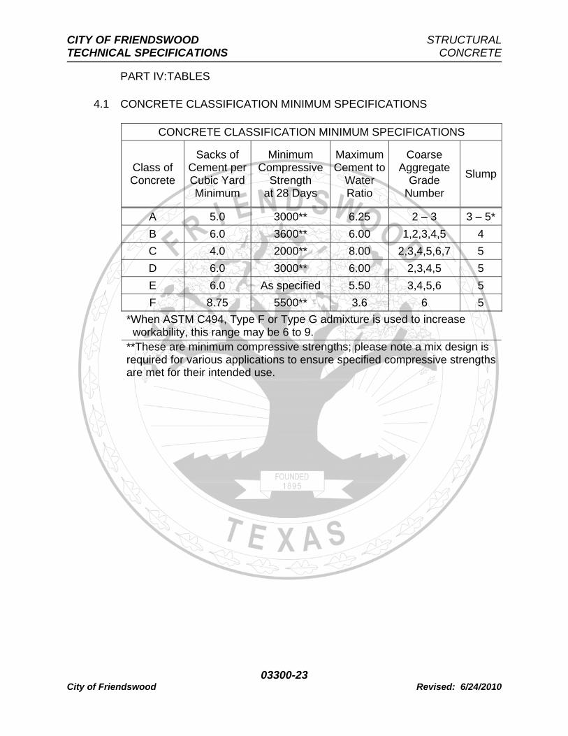
1.5 CONCRETE CLASSIFICATION AND USE
A. Classifications of concrete are for specific use and material only. Compressive Strengths shall vary depending on Designs, Details and Individual Technical Specifications, but at a minimum shall meet the minimum requirements as Specified in TABLE 4.1 – CONCRETE CLASSIFICATION MINIMUM REQUIREMENTS.
B. Class of concrete shall be identified as follows:
1. Class A Concrete – Paving, drilled shafts, non-structural culverts, inlets, manholes, curb, curb and gutter, sidewalk, driveway, wheelchair ramp, pilot channel and slope paving.
2. Class B Concrete – Paving, structural culverts, wingwall,
headwall and bridge structures. 3. Class C Concrete – Small signs, anchors, and pipe blocking. 4. Class D Concrete – Seal slab. 5. Class E Concrete – Prestressed concrete beams, boxes and
traffic barriers. 6. Class F – “High Early Strength” concrete for traffic surfaces
only and only with approval of Director of Community Development.
1.6 HANDLING AND STORAGE
A. Cement: Store cement off of ground in well-ventilated, weatherproof building to prevent deterioration or exposure to moisture. Different brands of cement or same brand from different sources shall not be
CITY OF FRIENDSWOOD STRUCTURAL TECHNICAL SPECIFICATIONS CONCRETE
03300-6 City of Friendswood Revised: 6/24/2010
used unless approved by the Director of Community Development or the Project Manager.
B. Aggregates: All aggregates shall be transported and stockpiled
separately according to their sources and gradations. Aggregates shall be handled in accordance with ACI requirements to prevent segregation and loss of fines or contamination with foreign materials.
1. If aggregates show segregation or the different grades become
mixed, aggregates shall be re-screened before placing in the proportioning bins.
2. Aggregates from different sources or different gradations shall
be segregated to prevent intermixing. Mixing of aggregates in stockpiles shall not be permitted.
3. No aggregate shall be transferred to proportioning bins when
the moisture content of the aggregate is such that it will affect the accuracy of proportioning. Such aggregates shall be removed and stockpiled until a dry surface condition is obtained.
PART II: PRODUCTS
2.1 CONCRETE MATERIALS
A. Portland cement concrete shall be composed of Portland cement fine aggregate, coarse aggregate, water and admixtures as approved by the Project Manager and shall be proportioned and mixed as specified in this Section.
B. Cementitious Material:
1. Portland Cement: ASTM C150, Type I/II, unless use of Type III is authorized by Project Manager; or ASTM C595, Type IP. For concrete in contact with sewage use Type II cement.
2. When aggregates are potentially reactive with alkalis in cement,
use cement not exceeding four pounds per cubic yard (4 Lbs/Cy) alkali content in form of Na2O + 0.658K20.
C. Water: Clean, free from harmful amounts of oils, acids, alkalis, organic
or other deleterious substances, and meeting requirements of ASTM C94. Water from municipal supplies approved by State agencies will not require testing, but water from other sources shall be tested before use in concrete.
CITY OF FRIENDSWOOD STRUCTURAL TECHNICAL SPECIFICATIONS CONCRETE
03300-7 City of Friendswood Revised: 6/24/2010
1. Tests shall be made in accordance with AASHTO T26. One
gallon (1 Gal) shall be taken to qualified testing laboratory for testing.
2. Water used in white Portland cement concrete shall be free
from iron and other impurities which may cause staining or discoloration.
D. Aggregate:
1. Coarse Aggregate: ASTM C33. Unless otherwise indicated, use following ASTM standard sizes: No. 357 or No. 467; No. 57 or No. 67, No. 7. Maximum size: Not larger than one-fifth (1/5) of narrowest dimension between sides of forms, nor larger than three-quarters (3/4) of minimum clear spacing between reinforcing bars. Coarse aggregates shall meet the requirements as specified in TABLE 4.2 – COARSE AGGREGATE GRADATION in this Section.
a. Coarse aggregate material shall be made of either
durable crushed or uncrushed gravel, crushed stone having uniform quality throughout. All coarse aggregate material shall have a wear of not more than forty percent (40%).
b. Deleterious substance shall have a maximum
permissible percentage by weight as specified in TABLE 4.3 – DELETERIOUS SUBSTANCES in this Section. Aggregate to be free from excess of salt, alkali, vegetable matter or other objectionable material either free or as adherent coating.
2. Fine Aggregate: ASTM C33. Fine aggregates shall meet the
requirements as specified in TABLE 4.4 – FINE AGGREGATE GRADATION in this Section. Fine aggregates shall be sand or combination of sand and not more than fifty percent (50%) stone screenings.
a. Sand shall be clean, hard, durable and uncoated
grains. b. Stone screenings shall be clean, hard, durable and
uncoated fragments resulting from crushing of stone.
3. Determine potential reactivity of fine and coarse aggregate in
CITY OF FRIENDSWOOD STRUCTURAL TECHNICAL SPECIFICATIONS CONCRETE
03300-8 City of Friendswood Revised: 6/24/2010
accordance with Appendix to ASTM C33. 4. Mineral filler – The addition of stone dust and/or sand as filler in
Portland Cement Concrete paving may be used when approved by the Project Manager. Stone dust and sand shall be of acceptable quality and cleanliness as a mineral filler to improve workability and plasticity of the concrete mixture, in amounts not to exceed fifteen percent (15%) of the weight of fine aggregate. When tested with standard laboratory sieves, the mineral filler shall meet the requirements as specified in TABLE 4.5 – MINERAL FILLERS in this Section. Fly Ash shall not be used as a filler unless approved by the Director of Community Development. If approval has been granted for use of Fly Ash, then fly ash shall conform to ASTM C618.
E. Air Entraining Admixtures: An air entraining agent shall be required and
shall conform to ASTM C260. Air entrainment shall be four percent (4%) plus or minus one percent (±1%) for all concrete classes and verified for conformity in the field by a certified testing laboratory. Concrete with air entrainment quantity of five percent and one-half (5.5%) to seven percent (7.0%) may be accepted on condition of passing twenty-eight day (28 D) compressive strength tests and approval of the Project Manager. Concrete with air entrainment quantity greater than seven percent (7%) or less than two percent (2%) shall be rejected. Air content shall be determined by ASTM C138 or ASTM C173. No air entrainment shall be required for seal slabs.
F. Chemical Admixtures:
1. Water Reducers: ASTM C494, Type A. 2. Water Reducing Retarders: ASTM C494, Type D. 3. High Range Water Reducers (Superplasticizers): ASTM C494,
Types F and G.
G. Prohibited Admixtures: No admixtures containing calcium chloride, thiocyanate, or materials that contribute free chloride ions in excess of one tenth of a percent (0.1%) by weight of cement shall be used in concrete mixes.
H. Fiber:
1. Fibrillated Polypropylene Fiber:
a. Addition Rate: One and one-half pounds (1-1/2 Lbs) of
CITY OF FRIENDSWOOD STRUCTURAL TECHNICAL SPECIFICATIONS CONCRETE
03300-9 City of Friendswood Revised: 6/24/2010
fiber per cubic yard of concrete. b. Physical Properties:
(1) Material: Polypropylene. (2) Length: One-half inch (1/2 In) or greater. (3) Specific Gravity: 0.91.
c. Acceptable Manufacturer: W. R. Grace Company, Fibermesh, or approved equal.
2. Steel Fiber: Comply with applicable provisions of ACI 544 and
ASTM A820.
a. Ratio: Fifty pounds (50 Lbs) to two hundred pounds (200 Lbs) of fiber per cubic yard of concrete.
b. Physical Properties.
(1) Material: Steel. (2) Aspect Ratio [for fiber lengths of one-half inch
(1/2 In) to two and one-half inch (2-1/2 In), length divided by diameter or equivalent diameter]: Thirty to One (30:1) – one hundred to one (100:1).
(3) Specific Gravity: 7.8. (4) Tensile Strength: Forty kilo-pounds per square
inch (40 ksi) – four hundred kilo-pounds per square inch (400 ksi).
(5) Young's Modulus: Twenty-nine thousand kilo-
pounds per square inch (29,000 ksi). (6) Minimum Average Tensile Strength: Fifty
thousand kilo-pounds per square inch (50,000 psi).
(7) Bending Requirements: Withstand bending
around one eighth inch (0.125 In) diameter mandrel to angle of ninety degrees Fahrenheit (90° F), at temperatures not less than sixty degrees Fahrenheit (60° F), without breaking.
CITY OF FRIENDSWOOD STRUCTURAL TECHNICAL SPECIFICATIONS CONCRETE
03300-10 City of Friendswood Revised: 6/24/2010
I. Curing Compounds: Type 2 white-pigmented liquid membrane-forming
compounds conforming to ASTM C309.
2.2 PRODUCTION METHODS
A. Use either ready-mixed concrete from a source approved by the Director of Community Development conforming to requirements of ASTM C94, or concrete produced by volumetric batching and continuous mixing in accordance with ASTM C685.
2.3 MEASUREMENT OF MATERIALS
A. Measure dry materials by weight, except volumetric proportioning may be used when concrete is batched and mixed in accordance with ASTM C685.
B. Measure water and liquid admixtures by volume.
2.4 DESIGN MIX
A. Use design mixes prepared by certified testing laboratory in accordance with ASTM C1077 and conforming to requirements of this Section. Design shall be based on the required over-design factor according to ASTM C94 and assuming a coefficient of variation equal to fifteen (15). The average of three (3) consecutive strength tests shall be equal to or greater than the specified strength. Classification shall meet the requirements as specified in TABLE 4.1 – CONCRETE CLASSIFICATION MINIMUM SPECIFICATIONS in this Section.
B. Proportion of concrete materials shall be based on ACI 211.1 to comply
with durability and strength requirements of ACI 318, Chapters 4 and 5, and this Specification. Submit concrete mix designs to Project Manager for review and approval.
C. Variations in proportions of concrete may be based on field experience
or trial mixtures, in accordance with requirements at Section 5.3 of ACI 318, may be made, but only when approved by Project Manager.
D. Proportioning of Portland Cement and water shall meet the
requirements as specified in TABLE 4.1 – CONCRETE CLASSIFICATION MINIMUM SPECIFICATIONS in this Section.
E. Add steel or polypropylene fibers only when called for on The Drawings
or in another Section of these Technical Specifications.
CITY OF FRIENDSWOOD STRUCTURAL TECHNICAL SPECIFICATIONS CONCRETE
03300-11 City of Friendswood Revised: 6/24/2010
F. Determine air content in accordance with ASTM C138, ASTM C173 or
ASTM C231. G. Once a design mix for any class of concrete has been approved by the
Project Manager, the mix shall not be varied as to source, quantity, quality, grading of materials, proportioning of any other way except as allowed for moisture adjustment and tolerances as specified in ASTM C685.
PART III: EXECUTION
3.1 BATCHING AND MIXING
A. Measure, batch, mix, and deliver ready-mixed concrete in accordance with ASTM C94, Sections 8 through 11. Produce ready-mixed concrete using automatic batching system as described in NRMCA Concrete Plant Standards, Part 2 – Plant Control Systems.
B. Measure, mix and deliver concrete produced by volumetric batching
and continuous mixing in accordance with ASTM C685, Sections 6 though 8.
C. Maintain concrete workability without segregation of material and
excessive bleeding. Obtain approval of Project Manager before adjustment and change of mix proportions.
D. Ready-mixed concrete delivered to site shall be accompanied by batch
tickets providing information required by ASTM C94, Section 16. Concrete produced by continuous mixing shall be accompanied by batch tickets providing information required by ASTM C685, Section 14. Water withheld from the mix shall also be noted on the batch ticket. In addition to the referenced information, each batch ticket shall also include the design mix information so that the batch can be compared on site to the mix design.
E. Clean, maintain and operate equipment so that it thoroughly mixes
material as required. F. Moisture Control:
1. At the time of batching, all aggregates shall have been dried or drained sufficiently to result in a stable moisture content such that no visible separation of water from aggregate will take place during transportation from the proportioning plant to the point of mixing.
CITY OF FRIENDSWOOD STRUCTURAL TECHNICAL SPECIFICATIONS CONCRETE
03300-12 City of Friendswood Revised: 6/24/2010
2. In no event shall the free moisture content of the fine aggregate
at the time of batching exceed eight percent (8%) of its saturated, surface-dry weight. The batch-to-batch uniformity of all aggregates shall be such that variations in moisture content within one hour (1 Hr) do not exceed twelve pounds (12 Lbs) in the batch quantity for one cubic yard (1 Cy) of concrete, or that a gradual change does not exceed twenty-four pounds (24 Lbs) in a period of four hours (4 Hrs).
3. The Contractor shall install, and maintain in operating condition,
an electrically actuated moisture meter which will indicate on a readily visible scale the percentage of moisture in the fine aggregate as it is batched, within a sensitivity of one-half percent (1/2%) by weight of the fine aggregate.
G. Scales
1. Scales shall be used for the accurate measurement of each of the materials entering each batch of concrete.
2. If scales are of the dial type, the dial shall be of such size and
so arranged that it may be read easily from the operating platform.
3. If scales are of the multiple beam type, the scales shall be
provided with an indicator operated by the main beam which will give positive visible evidence of over or underweight. The indicator shall be so designed that it will operate during the addition of the last two hundred pounds (200 Lbs) of material of any weighing. The over-travel of the indicator hand shall be at least one-third (1/3) of the loading travel. Indicators shall be enclosed to protect against moisture and dust.
4. Scales shall be tested by a commercial scale company and
certified that the scales meet all requirement for weighing equipment. Certification shall be required whenever a scale is relocated, and at least once every six months (6 Mos). Copies of the certifications shall be provided to the Project Manager when requested.
H. Recorders
1. An accurate recorder shall be provided for producing a digital printout of the batch number and scale readings corresponding to each of the ingredients of each concrete batch, including
CITY OF FRIENDSWOOD STRUCTURAL TECHNICAL SPECIFICATIONS CONCRETE
03300-13 City of Friendswood Revised: 6/24/2010
zero (0) initial readings. The individual ingredients shall be indicated by name or code corresponding to each weight.
2. Each printout shall indicate date and time of batching,
identification number identical to that of the concrete delivery ticket and codes for the mix design and of the Work.
3. The printout shall be prepared in duplicate, with one (1) copy
delivered together with its corresponding concrete delivery ticket to the Project Manager, as specified herein before.
4. Each recorder mechanism shall be enclosed in a locked, dust
tight cabinet and shall be placed in a position convenient for observation.
3.2 DELIVERY AND DELIVERY EQUIPMENT
A. Hand-mixed concrete shall be made in batches not larger than one-third cubic yard (1/3 Cy) and only with approval of the Project Manager. Concrete shall be Sakrete or approved equal, no separate proportioning of materials outside of a batch plant will be allowed. Batching shall be in accordance with manufactures directions and stated measurements.
1. Mixing of concrete shall be in a clean, water tight mixing box. 2. Introduce measured amount of clean water. 3. Mix water and cement a minimum of six (6) turns or until batch
maintains uniform color and consistency. 4. At no time shall bags of Sakrete be put in place, sliced open
and water added in a ditch or hole.
B. Pumping and pneumatic conveying equipment shall be of a suitable kind with adequate pumping capacity. Equipment shall be cleaned at the end of each operation. Pneumatic placement shall be controlled so that segregation does not occur in the discharged concrete. Concrete shall not be conveyed through any pipe made of aluminum or aluminum alloy.
C. Transit mix trucks shall be in good working order. All trucks shall have
the following operational, delivery and placing conditions and equipment:
1. Actuated drum revolution counter shall be in good working
order.
CITY OF FRIENDSWOOD STRUCTURAL TECHNICAL SPECIFICATIONS CONCRETE
03300-14 City of Friendswood Revised: 6/24/2010
a. Batch shall be mixed at the plant between fifty (50) and
seventy (70) revolutions before being transported to site.
b. At no time shall a batch be placed when mixed less
than seventy (70) revolutions or more than 100 revolutions, except as noted in 3.2.C.1.c.
c. Batch shall be mixed for a minimum of twenty-five (25)
revolutions after additional water has been introduced into the mix on site. This procedure shall be repeated for each instance when water is added.
2. Water supply reserve tank shall be supplied on each truck.
a. Water tank shall be full on arrival at site. b. Water tank shall have accurate scale to measure
gallons of water to be introduced to truck mixer. c. Project Manger shall verify the amount of water used
on site for mixing and verify the recording on the trip ticket.
3. Drum mixer shall be watertight and shall be free of hardened
concrete and shall have fins that are capable of thoroughly mixing concrete.
4. Any defective equipment that cannot meet the Specifications of
3.2.C shall not be allowed on site until the deficiencies have been corrected.
3.3 PLACING CONCRETE
A. Give sufficient advance notice to the Project Manager [at least forty-eight hours (48 Hrs) prior to commencement of operations] to permit inspection of forms, reinforcing steel, embedded items and other preparations for placing concrete. Place no concrete prior to the Project Manager's approval.
B. Schedule concrete placing to permit completion of finishing operations
in daylight hours. However, when necessary to continue after daylight hours, site shall be illuminated completely as required. When rainfall occurs after placing operations are started, provide covering to protect work.
CITY OF FRIENDSWOOD STRUCTURAL TECHNICAL SPECIFICATIONS CONCRETE
03300-15 City of Friendswood Revised: 6/24/2010
C. Subgrade surface shall be sprinkled sufficiently with water to prevent
absorption of water from freshly placed concrete. D. Forms and rebar shall be cleaned of all foreign materials; subgrade
shall be free of all trash and other materials. E. Batches that do not have computer batch tickets or delivery tickets shall
be refused. Once a truck has been refused for any reason it shall leave the site. Attempts to fix deficiencies on site shall not be allowed.
F. Temperature specifications for placement of concrete shall be as
follows and as specified in TABLE 4.6 – TEMPERATURE REQUIREMENTS FOR PLACEMENT in this Section:
1. Ambient (Air) temperature shall be taken in the shade and
shielded from direct sunlight and wind. 2. Minimum ambient temperature for concrete placement shall be
thirty-five degrees Fahrenheit (35° F) and rising. At no time shall concrete be placed when ambient temperature is below forty degrees Fahrenheit (40° F) and falling.
3. Maximum ambient temperature shall be ninety degrees
Fahrenheit (90° F). Addition of ice to concrete mix shall allow ambient temperature maximum to be one hundred degrees Fahrenheit (100° F), upon approval of the Project Manager.
4. Minimum concrete temperature shall be fifty degrees
Fahrenheit (50° F). 5. Maximum concrete temperature shall be ninety degrees
Fahrenheit (90° F). Addition of ice shall permit the maximum temperature to be ninety-five degrees Fahrenheit (95° F). At no time shall any concrete be placed when concrete temperature exceeds ninety-five degrees Fahrenheit (95° F).
G. When adverse weather conditions affect quality of concrete, postpone
concrete placement. Protect placed concrete from temperatures below thirty-two degrees Fahrenheit (32° F) until concrete has cured for minimum of three days (3 D) at seventy degrees Fahrenheit (70° F) or five days (5 D) at fifty degrees Fahrenheit (50° F).
H. Time constraints – Concrete shall be placed so that there is no more than one hour (1 Hr) of time elapsed from last discharge to next discharge. Addition of allowable dosage of water retardation agent
CITY OF FRIENDSWOOD STRUCTURAL TECHNICAL SPECIFICATIONS CONCRETE
03300-16 City of Friendswood Revised: 6/24/2010
shall extend time limit by one-half hour (1/2 Hr). Limit on time from batch to placement shall be as specified in TABLE 4.7 – TRANSPORTING TIME REQUIREMENTS in this Section.
I. If no water has been withheld from the mix at the plant, then addition of
water to mix on site shall not exceed two gallons per cubic yard (2 Gal/Cy) of concrete. If water has been withheld, then up to the amount withheld can be added upon approval of the Project Manager. Any additional water above that, but not to exceed two gallons per cubic yard (2 Gal/Cy), shall be added only with the approval of the Project Manager. At no time shall slump exceed mix design nor be more than one and one-half inches (1-1/2 In) less than specified slump. All water that has been added to the truck shall be written on the trip ticket and batch ticket by the Project Manager.
J. Use troughs, pipes and chutes lined with approved metal or synthetic
material for placing concrete so that concrete ingredients are not separated. Keep chutes, troughs and pipes clean and free from coatings of hardened concrete. Allow no aluminum or aluminum alloy material to come in contact with concrete.
K. Limit free fall of concrete to four feet (4 Ft). Do not deposit large
quantities of concrete at one location so that running or working concrete along forms is required. Do not jar forms after concrete has taken initial set, and do not place strain on projecting reinforcement rods or anchor bolts.
L. Use tremies for placing concrete in walls and similar narrow or
restricted locations. Use tremies made in sections, or provide in several lengths, so that outlet may be adjusted to proper height during placing operations.
M. Place concrete in continuous horizontal layers approximately twelve
inches (12 In) thick. Place each layer while layer below is still plastic. N. Compact each layer of concrete with concrete spading implements and
mechanical vibrators of approved type and adequate number for size of placement. When immersion vibrators cannot be used, use form vibrators. Apply vibrators to concrete immediately after depositing. Move vibrator vertically through layer of concrete just placed and several inches into plastic layer below. Do not penetrate or disturb layers previously placed which have partially set. Do not use vibrators to aid lateral flow concrete. Closely supervise consolidation to ensure uniform insertion and duration of immersion.
O. Handling and Placing Concrete: Conform to ACI 302.1R, ACI 304R
CITY OF FRIENDSWOOD STRUCTURAL TECHNICAL SPECIFICATIONS CONCRETE
03300-17 City of Friendswood Revised: 6/24/2010
and ACI 309R.
3.4 FIELD QUALITY CONTROL
A. Testing shall be performed under provisions of Sections 01470 – Testing Laboratory Services and 01475 – Quality Control Testing Procedures.
B. Unless otherwise directed by the Project Manager, the following
minimum testing of concrete shall be required. Testing shall be performed by qualified individuals employed by approved independent testing laboratory, and conform to requirements of ASTM C1077.
1. Take concrete samples in accordance with ASTM C172. 2. Make one (1) set of compression test specimens for each mix
design at least once per day and for each one hundred cubic yards (100 Cy) or fraction thereof. Make, cure and test specimens in accordance with ASTM C31 and ASTM C39.
a. Tests are representative random sampling of each one
hundred cubic yard (100 Cy) unit placement of concrete. Passing or failure of compressive testing shall represent all one hundred cubic yard (100 Cy) for acceptance or deficiency.
3. When taking compression test specimens, test each sample for
slump according to ASTM C143, for temperature according to ASTM C1064, for air content according to ASTM C231, and for unit weight according to ASTM C138.
4. Inspect, sample and test concrete in accordance with ASTM
C94, Section 13, 14, and 15, and ACI 311-5R.
C. Test Cores: Conform to ASTM C42. D. Testing High Early Strength Concrete: When Type III cement is used in
concrete, specified seven day (7 D) and twenty-eight day (28 D) compressive strengths shall be applicable at three days (3 D) and seven days (7 D), respectively.
E. Seven day (7 D) compressive strengths shall be seventy (70%) percent
of twenty-eight day (28 D) strength requirement. F. If twenty-eight day (28 D) compressive strengths fail to meet class
specified requirements, then those portions of structure represented by
CITY OF FRIENDSWOOD STRUCTURAL TECHNICAL SPECIFICATIONS CONCRETE
03300-18 City of Friendswood Revised: 6/24/2010
test specimens shall be replaced at no additional cost to City. G. Take one (1) slump test a minimum of every fifty cubic yards (50 Cy) of
placement according to ASTM C143. Project Manager shall be authorized to have testing laboratory take slump on any questionable concrete.
3.5 FINISHING
A. Burlap drag or transverse broom for finishing slab.
1. Burlap Finish – Furnish four (4) plies of ten ounce (10 oz) burlap material fastened to bridge to form continuous strip of burlap full width of pavement. Maintain contact three foot (3 Ft) width of burlap material with pavement surface. Keep burlap drags clean and free of encrusted mortar. Burlap shall be dragged longitudinally (parallel) with the centerline of the roadway. Finish look shall be straight lined. Swoops, diagonals or ridges shall not be allowed.
2. Broom Finish – Furnish brooms with either horsehair or
synthetic fiber bristles. Straw bristles shall not be allowed. Keep bristles clean and free of encrusted mortar. Broom shall be dragged latitudinally (perpendicular) with the centerline of the roadway. Adequate combination of pressure and bristle thickness shall be used to provide medium to heavy texture. Finish look shall be straight lined. Swoops, diagonals or ridges shall not be allowed.
3. Fire hose finishing shall not be allowed.
B. Finishing for patches and structures shall conform to the following requirements.
1. Patch honeycomb, minor defects and form tie holes in concrete
surfaces with cement mortar mixed one part cement to two parts fine aggregate. Repair defects by cutting out unsatisfactory material and replacing with new concrete, securely keyed and bonded to existing concrete. Finish to make junctures between patches and existing concrete as inconspicuous as possible. Use stiff mixture and thoroughly tamp into place. After each patch has stiffened sufficiently to allow for greatest portion of shrinkage, strike off mortar flush with surface.
2. Apply rubbed finish to exposed surfaces of formed concrete
CITY OF FRIENDSWOOD STRUCTURAL TECHNICAL SPECIFICATIONS CONCRETE
03300-19 City of Friendswood Revised: 6/24/2010
structures as noted on The Drawings. After pointing has set sufficiently, wet surface with brush and perform first surface rubbing with No. 16 carborundum stone, or approved equal. Rub sufficiently to bring surface to paste, to remove form marks and projections, and to produce smooth, dense surface. Add cement to form surface paste as necessary. Spread or brush material, which has been ground to paste, uniformly over surface and allow to reset. In preparation for final acceptance, clean surfaces and perform final finish rubbing with No. 30 carborundum stone or approved equal. After rubbing, allow paste on surface to reset; then wash surface with clean water. Leave structure with clean, neat and uniform-appearing finish.
C. Finish tolerances shall be as follows:
1. Top concrete surface of sidewalks shall be true planes within one-quarter inch (1/4 In) in ten feet (10 Ft).
2. Wheelchair ramps shall be held to tolerances as stated in
Sections 02820 – Concrete Sidewalks and 02825 – Colored Concrete for Wheelchair Ramps.
3. Roadway slabs parallel to the centerline shall be true planes
within one-sixteenth inch (1/16 In) in ten feet (10 Ft). 4 All other surfaces shall be true planes within one-quarter inch
(1/4 In) in ten feet (10 Ft). 5. All tolerances shall be checked with a steel edge that has zero
(0) tolerance deviation.
3.6 CURING
A. Comply with ACI 308. Cure by preventing loss of moisture, rapid temperature change and mechanical injury for period of seven (7) curing days when Type II or IP cement has been used and for three (3) curing days when Type III cement has been used. Start curing as soon as free water has disappeared from concrete surface after placing and finishing. A curing day is any calendar day in which temperature is above fifty degrees Fahrenheit (50° F) for at least nineteen hours (19 Hrs). Colder days may be counted when air temperature adjacent to concrete is maintained above fifty degrees Fahrenheit (50° F). In continued cold weather, when artificial heat is not provided, removal of forms and shoring may be permitted at end of calendar days equal to twice required number of curing days. However, leave soffit forms and shores in place until concrete has reached specified twenty-eight day
CITY OF FRIENDSWOOD STRUCTURAL TECHNICAL SPECIFICATIONS CONCRETE
03300-20 City of Friendswood Revised: 6/24/2010
(28 D) strength, unless directed otherwise by the Project Manager.
1. Moisture Cover Curing Method: The concrete surfaces to be cured shall be covered with specific moisture-retaining cover material placed in the widest practical width with sides and ends lapped at least three inches (3 In) and sealed by waterproofing tape or adhesive. All holes or tears that develop during curing period shall be repaired immediately. Minimum curing time for this method shall be seven days (7 D).
2. Liquid Membrane Curing: The specified membrane curing
compound shall be applied to damp concrete surfaces as soon as possible after the final finishing operations are complete, but in no case later than two hours (2 Hrs) after finishing. Curing compound shall be applied uniformly over the concrete surfaces by means of approved spray equipment in accordance manufacturer’s instruction. No deformities (tear drop, pattern, etc.) shall be accepted. Should the cure coat be damaged from any cause during the curing period, damaged portions shall be repaired and recoated immediately with additional compound.
B. Formed surfaces not requiring rubbed-finished surface shall be cured
by leaving forms in place for full curing period. Keep wood forms wet during curing period. Add water as needed for other types of forms. Non-structural concrete forms, upon approval of the Project Manager, may be removed after two days (2 D) and curing compound applied.
C. Rubbed Finish:
1. For formed surfaces requiring rubbed finish, remove forms as soon as practicable without damaging surface.
2. After rubbed-finish operations are complete, continue curing
formed surfaces by using either approved curing/sealing compounds or moist cotton mats until normal curing period is complete.
D. Unformed Surfaces: Cure by membrane curing compound method.
1. After concrete has received final finish and surplus water sheen has disappeared, immediately seal surface with uniform coating of approved curing compound, applied at rate of coverage recommended by manufacturer or as directed by the Project Manager. Do not apply less than one gallon (1 Gal) per one hundred eighty square feet (180 Sf) of area. Provide satisfactory means to properly control and check rate of
CITY OF FRIENDSWOOD STRUCTURAL TECHNICAL SPECIFICATIONS CONCRETE
03300-21 City of Friendswood Revised: 6/24/2010
application of compound. 2. Thoroughly agitate compound during use and apply by means
of approved mechanical power pressure sprayers equipped with atomizing nozzles. For application on small miscellaneous items, hand-powered spray equipment may be used. Prevent loss of compound between nozzle and concrete surface during spraying operations.
3. Do not apply compound to dry surface. When concrete surface
has become dry, thoroughly moisten surface immediately prior to application of compound. At locations where coating shows discontinuities, pinholes or other defects, or when rain falls on newly coated surface before film has dried sufficiently to resist damage, additional coat of compound shall be applied at specified rate of coverage.
3.7 PROTECTION
A. Protect concrete against damage until final acceptance by City. B. Protect fresh concrete from damage due to rain, hail, sleet, or snow.
Provide protection while concrete is still plastic, and whenever precipitation is imminent or occurring.
C. Do not backfill around concrete structures or subject them to design
loadings until components of structure needed to resist loading are complete and have reached specified twenty-eight day (28 D) compressive strength, except as authorized otherwise by the Project Manager.
D. Concrete pavement shall not be used before the twenty-eight day (28
D) compressive strength unless the seven day (7 D) compressive strength test has reached the twenty-eight day (28 D) strength requirement. Pavement can be used for light vehicles only after the twenty-eight day (28 D) strength has been met. At no time shall any equipment or vehicles heavier than eight thousand pounds (8000 Lbs) GVW (Gross Vehicle Weight) be allowed on pavement before it passes the twenty-eight day (28 D) compressive strength tests.
3.8 REMOVAL OF FORMS AND SHORING
A. Remove forms from surfaces requiring rubbing only as rapidly as rubbing operation progresses. Remove forms from vertical surfaces not requiring rubbed-finish when concrete has aged for required number of curing days. When curing compound is used, do not remove forms
CITY OF FRIENDSWOOD STRUCTURAL TECHNICAL SPECIFICATIONS CONCRETE
03300-22 City of Friendswood Revised: 6/24/2010
before during first (1st) two (2) full days after concrete placement. B. Leave soffit forms and shores in place until concrete has reached
specified twenty-eight day (28 D) strength, unless directed otherwise by the Project Manager.
3.9 DEFECTIVE WORK
A. Immediately repair defective work discovered after forms have been removed. When concrete surface is bulged, uneven, or shows excess honeycombing or form marks which cannot be repaired satisfactorily through patching, remove and replace entire section.
CITY OF FRIENDSWOOD STRUCTURAL TECHNICAL SPECIFICATIONS CONCRETE
A 5.0 3000** 6.25 2 – 3 3 – 5*B 6.0 3600** 6.00 1,2,3,4,5 4 C 4.0 2000** 8.00 2,3,4,5,6,7 5 D 6.0 3000** 6.00 2,3,4,5 5 E 6.0 As specified 5.50 3,4,5,6 5 F 8.75 5500** 3.6 6 5
*When ASTM C494, Type F or Type G admixture is used to increase workability, this range may be 6 to 9. **These are minimum compressive strengths; please note a mix design is required for various applications to ensure specified compressive strengths are met for their intended use.
CITY OF FRIENDSWOOD STRUCTURAL TECHNICAL SPECIFICATIONS CONCRETE
03300-24 City of Friendswood Revised: 6/24/2010
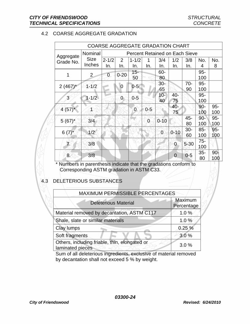
4.2 COARSE AGGREGATE GRADATION
COARSE AGGREGATE GRADATION CHART Percent Retained on Each Sieve Aggregate
Grade No.
Nominal Size
Inches 2-1/2
In. 2
In. 1-1/2
In. 1
In. 3/4 In.
1/2 In.
3/8 In.
No. 4
No. 8
1 2 0 0-20 15-50 60-
80 95-100
2 (467)* 1-1/2 0 0-5 30-65 70-
90 95-100
3 1-1/2 0 0-5 10-40
40-75 95-
100
4 (57)* 1 0 0-5 40-75 90-
10095-100
5 (67)* 3/4 0 0-10 45-80
90-100
95-100
6 (7)* 1/2 0 0-10 30-60
85-100
95-100
7 3/8 0 5-30 75-100
8 3/8 0 0-5 35-80
90-100
* Numbers in parenthesis indicate that the gradations conform to Corresponding ASTM gradation in ASTM C33.
4.3 DELETERIOUS SUBSTANCES
MAXIMUM PERMISSIBLE PERCENTAGES
Deleterious Material Maximum Percentage
Material removed by decantation, ASTM C117 1.0 % Shale, slate or similar materials 1.0 % Clay lumps 0.25 % Soft fragments 3.0 % Others, including friable, thin, elongated or laminated pieces 3.0 %
Sum of all deleterious ingredients, exclusive of material removed by decantation shall not exceed 5 % by weight.
CITY OF FRIENDSWOOD STRUCTURAL TECHNICAL SPECIFICATIONS CONCRETE
03300-25 City of Friendswood Revised: 6/24/2010
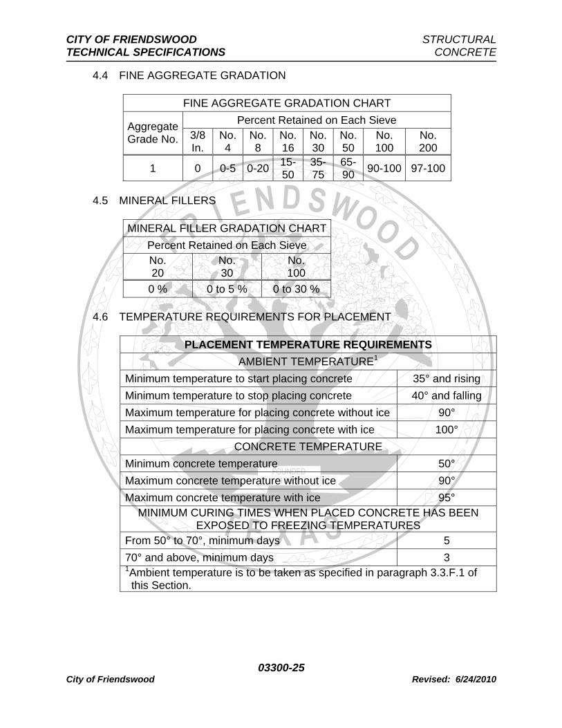
4.4 FINE AGGREGATE GRADATION
FINE AGGREGATE GRADATION CHART Percent Retained on Each Sieve Aggregate
Grade No. 3/8 In.
No. 4
No. 8
No. 16
No. 30
No. 50
No. 100
No. 200
1 0 0-5 0-20 15-50
35-75
65-90 90-100 97-100
4.5 MINERAL FILLERS
MINERAL FILLER GRADATION CHARTPercent Retained on Each Sieve No. 20
No. 30
No. 100
0 % 0 to 5 % 0 to 30 % 4.6 TEMPERATURE REQUIREMENTS FOR PLACEMENT
PLACEMENT TEMPERATURE REQUIREMENTS AMBIENT TEMPERATURE1
Minimum temperature to start placing concrete 35° and rising Minimum temperature to stop placing concrete 40° and falling Maximum temperature for placing concrete without ice 90° Maximum temperature for placing concrete with ice 100°
CONCRETE TEMPERATURE Minimum concrete temperature 50° Maximum concrete temperature without ice 90° Maximum concrete temperature with ice 95°
MINIMUM CURING TIMES WHEN PLACED CONCRETE HAS BEEN EXPOSED TO FREEZING TEMPERATURES
From 50° to 70°, minimum days 5 70° and above, minimum days 3 1Ambient temperature is to be taken as specified in paragraph 3.3.F.1 of this Section.
CITY OF FRIENDSWOOD STRUCTURAL TECHNICAL SPECIFICATIONS CONCRETE
03300-26 City of Friendswood Revised: 6/24/2010
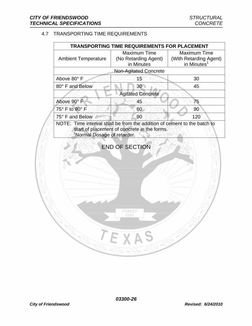
4.7 TRANSPORTING TIME REQUIREMENTS
TRANSPORTING TIME REQUIREMENTS FOR PLACEMENT
Ambient Temperature Maximum Time
(No Retarding Agent) in Minutes
Maximum Time (With Retarding Agent)
in Minutes1 Non-Agitated Concrete
Above 80° F 15 30 80° F and Below 30 45
Agitated Concrete Above 90° F 45 75 75° F to 90° F 60 90 75° F and Below 90 120 NOTE: Time interval shall be from the addition of cement to the batch to start of placement of concrete in the forms. 1Normal Dosage of retarder.