60
L4 P/N 9000-0577:L4 ECN 16-0032 Document: 9000-0577 2/02/2016 Rev: E3 Series ® Classic Installation/Operation Manual

L4P/N 9000-0577:L4 ECN 16-0032
Document: 9000-05772/02/2016 Rev:
E3 Series® ClassicInstallation/Operation
Manual
Fire Alarm & Emergency Communication System LimitationsWhile a life safety system may lower insurance rates, it is not a substitute for life and property insurance!An automatic fire alarm system—typically made up of smoke detectors, heat detectors, manual pull stations, audible warning devices, and a fire alarm control panel (FACP) with remote notifi-cation capability—can provide early warning of a developing fire. Such a system, however, does not assure protection against property damage or loss of life resulting from a fire.
An emergency communication system—typically made up of an automatic fire alarm system (as described above) and a life safety communication system that may include an autonomous control unit (ACU), local operating console (LOC), voice commu-nication, and other various interoperable communication meth-ods—can broadcast a mass notification message. Such a system, however, does not assure protection against property damage or loss of life resulting from a fire or life safety event.
The Manufacturer recommends that smoke and/or heat detectors be located throughout a protected premises following the recommendations of the current edition of the National Fire Protection Association Standard 72 (NFPA 72), manufacturer's recommendations, State and local codes, and the recommendations contained in the Guide for Proper Use of System Smoke Detectors, which is made available at no charge to all installing dealers. This document can be found at http://www.systemsensor.com/appguides/. A study by the Federal Emergency Management Agency (an agency of the United States government) indicated that smoke detectors may not go off in as many as 35% of all fires. While fire alarm systems are designed to provide early warning against fire, they do not guarantee warning or protection against fire. A fire alarm system may not provide timely or adequate warning, or simply may not function, for a variety of reasons:
Smoke detectors may not sense fire where smoke cannot reach the detectors such as in chimneys, in or behind walls, on roofs, or on the other side of closed doors. Smoke detectors also may not sense a fire on another level or floor of a building. A sec-ond-floor detector, for example, may not sense a first-floor or basement fire.
Particles of combustion or “smoke” from a developing fire may not reach the sensing chambers of smoke detectors because:
• Barriers such as closed or partially closed doors, walls, chim-neys, even wet or humid areas may inhibit particle or smoke flow.
• Smoke particles may become “cold,” stratify, and not reach the ceiling or upper walls where detectors are located.
• Smoke particles may be blown away from detectors by air outlets, such as air conditioning vents.
• Smoke particles may be drawn into air returns before reach-ing the detector.
The amount of “smoke” present may be insufficient to alarm smoke detectors. Smoke detectors are designed to alarm at var-ious levels of smoke density. If such density levels are not cre-ated by a developing fire at the location of detectors, the detectors will not go into alarm.
Smoke detectors, even when working properly, have sensing limitations. Detectors that have photoelectronic sensing cham-bers tend to detect smoldering fires better than flaming fires, which have little visible smoke. Detectors that have ionizing-type sensing chambers tend to detect fast-flaming fires better than smoldering fires. Because fires develop in different ways and are often unpredictable in their growth, neither type of detector is necessarily best and a given type of detector may not provide adequate warning of a fire.
Smoke detectors cannot be expected to provide adequate warn-ing of fires caused by arson, children playing with matches (especially in bedrooms), smoking in bed, and violent explosions
(caused by escaping gas, improper storage of flammable materi-als, etc.).
Heat detectors do not sense particles of combustion and alarm only when heat on their sensors increases at a predetermined rate or reaches a predetermined level. Rate-of-rise heat detec-tors may be subject to reduced sensitivity over time. For this rea-son, the rate-of-rise feature of each detector should be tested at least once per year by a qualified fire protection specialist. Heat detectors are designed to protect property, not life.
IMPORTANT! Smoke detectors must be installed in the same room as the control panel and in rooms used by the system for the connection of alarm transmission wiring, communications, signaling, and/or power. If detectors are not so located, a devel-oping fire may damage the alarm system, compromising its abil-ity to report a fire.
Audible warning devices such as bells, horns, strobes, speakers and displays may not alert people if these devices are located on the other side of closed or partly open doors or are located on another floor of a building. Any warning device may fail to alert people with a disability or those who have recently consumed drugs, alcohol, or medication. Please note that:
• An emergency communication system may take priority over a fire alarm system in the event of a life safety emergency.
• Voice messaging systems must be designed to meet intelligi-bility requirements as defined by NFPA, local codes, and Authorities Having Jurisdiction (AHJ).
• Language and instructional requirements must be clearly dis-seminated on any local displays.
• Strobes can, under certain circumstances, cause seizures in people with conditions such as epilepsy.
• Studies have shown that certain people, even when they hear a fire alarm signal, do not respond to or comprehend the meaning of the signal. Audible devices, such as horns and bells, can have different tonal patterns and frequencies. It is the property owner's responsibility to conduct fire drills and other training exercises to make people aware of fire alarm signals and instruct them on the proper reaction to alarm sig-nals.
• In rare instances, the sounding of a warning device can cause temporary or permanent hearing loss.
A life safety system will not operate without any electrical power. If AC power fails, the system will operate from standby batteries only for a specified time and only if the batteries have been properly maintained and replaced regularly.
Equipment used in the system may not be technically compat-ible with the control panel. It is essential to use only equipment listed for service with your control panel.
Telephone lines needed to transmit alarm signals from a prem-ises to a central monitoring station may be out of service or tem-porarily disabled. For added protection against telephone line failure, backup radio transmission systems are recommended.
The most common cause of life safety system malfunction is inadequate maintenance. To keep the entire life safety system in excellent working order, ongoing maintenance is required per the manufacturer's recommendations, and UL and NFPA standards. At a minimum, the requirements of NFPA 72 shall be followed. Environments with large amounts of dust, dirt, or high air velocity require more frequent maintenance. A maintenance agreement should be arranged through the local manufacturer's representa-tive. Maintenance should be scheduled as required by National and/or local fire codes and should be performed by authorized professional life safety system installers only. Adequate written records of all inspections should be kept.
Limit-D2-2016
2 E3 Series Broadband Installation/Operation Manual — P/N 9000-0577:L4 2/02/2016
Installation PrecautionsAdherence to the following will aid in problem-free installation with long-term reliability:WARNING - Several different sources of power can be connected to the fire alarm control panel. Disconnect all sources of power before servicing. Control unit and associ-ated equipment may be damaged by removing and/or insert-ing cards, modules, or interconnecting cables while the unit is energized. Do not attempt to install, service, or operate this unit until manuals are read and understood.
CAUTION - System Re-acceptance Test after Software Changes: To ensure proper system operation, this product must be tested in accordance with NFPA 72 after any pro-gramming operation or change in site-specific software. Re-acceptance testing is required after any change, addition or deletion of system components, or after any modification, repair or adjustment to system hardware or wiring. All compo-nents, circuits, system operations, or software functions known to be affected by a change must be 100% tested. In addition, to ensure that other operations are not inadvertently affected, at least 10% of initiating devices that are not directly affected by the change, up to a maximum of 50 devices, must also be tested and proper system operation verified.
This system meets NFPA requirements for operation at 0-49º C/32-120º F and at a relative humidity 93% ± 2% RH (non-condensing) at 32°C ± 2°C (90°F ± 3°F). However, the useful life of the system's standby batteries and the electronic com-ponents may be adversely affected by extreme temperature ranges and humidity. Therefore, it is recommended that this system and its peripherals be installed in an environment with a normal room temperature of 15-27º C/60-80º F.
Verify that wire sizes are adequate for all initiating and indi-cating device loops. Most devices cannot tolerate more than a 10% I.R. drop from the specified device voltage.
Like all solid state electronic devices, this system may operate erratically or can be damaged when subjected to light-ning induced transients. Although no system is completely immune from lightning transients and interference, proper grounding will reduce susceptibility. Overhead or outside aerial wiring is not recommended, due to an increased susceptibility to nearby lightning strikes. Consult with the Technical Ser-vices Department if any problems are anticipated or encoun-tered.
Disconnect AC power and batteries prior to removing or inserting circuit boards. Failure to do so can damage circuits.
Remove all electronic assemblies prior to any drilling, filing, reaming, or punching of the enclosure. When possible, make all cable entries from the sides or rear. Before making modifi-cations, verify that they will not interfere with battery, trans-former, or printed circuit board location.
Do not tighten screw terminals more than 9 in-lbs. Over-tightening may damage threads, resulting in reduced terminal contact pressure and difficulty with screw terminal removal.
This system contains static-sensitive components. Always ground yourself with a proper wrist strap before han-dling any circuits so that static charges are removed from the body. Use static suppressive packaging to protect electronic assemblies removed from the unit.
Follow the instructions in the installation, operating, and pro-gramming manuals. These instructions must be followed to avoid damage to the control panel and associated equipment. FACP operation and reliability depend upon proper installation.
Precau-D1-9-2005
FCC WarningWARNING: This equipment generates, uses, and can radiate radio frequency energy and if not installed and used in accordance with the instruction manual may cause interference to radio communications. It has been tested and found to comply with the limits for class A computing devices pursuant to Subpart B of Part 15 of FCC Rules, which is designed to provide reasonable protection against such interference when devices are operated in a commercial environment. Operation of this equipment in a residential area is likely to cause interfer-ence, in which case the user will be required to correct the interference at his or her own expense.
Canadian Requirements
This digital apparatus does not exceed the Class A limits for radiation noise emissions from digital apparatus set out in the Radio Interference Regulations of the Cana-dian Department of Communications.
Le present appareil numerique n'emet pas de bruits radi-oelectriques depassant les limites applicables aux appa-reils numeriques de la classe A prescrites dans le Reglement sur le brouillage radioelectrique edicte par le ministere des Communications du Canada.
eVance™ is a trademark; and Acclimate®, FocalPoint®, Gamewell-FCI®, FAAST Fire Alarm Aspiration Sensing Technology®, Intelligent FAAST®,SmartScan®, SWIFT®, Velociti®, and E3 Series® are registered trademarks of Honeywell International Inc.eVance™ is a trademark; and Silent Knight®and SWIFT® are registered trademarks of Honeywell International Inc. Microsoft® and Windows® are registered trademarks of the Microsoft Corporation.Chrome™ and Google™ are trademarks of Google Inc.
©2016 by Honeywell International Inc. All rights reserved. Unauthorized use of this document is strictly prohibited.
E3 Series Broadband Installation/Operation Manual — P/N 9000-0577:L4 2/02/2016 3

Software DownloadsIn order to supply the latest features and functionality in fire alarm and life safety technology to our customers, we make frequent upgrades to the embedded software in our products. To ensure that you are installing and programming the latest features, we strongly recommend that you download the most current version of software for each product prior to commissioning any system. Contact Technical Support with any questions about software and the appropriate version for a specific application.
Documentation FeedbackYour feedback helps us keep our documentation up-to-date and accurate. If you have any comments or suggestions about our online Help or printed manuals, you can email us.
Please include the following information:
•Product name and version number (if applicable)
•Printed manual or online Help
•Topic Title (for online Help)
•Page number (for printed manual)
•Brief description of content you think should be improved or corrected
•Your suggestion for how to correct/improve documentation
Send email messages to:
Please note this email address is for documentation feedback only. If you have any technical issues, please contact Technical Services.
4 E3 Series Broadband Installation/Operation Manual — P/N 9000-0577:L4 2/02/2016

Table of Contents
Table of Contents
1.1: Standards........................................................................................................................................................71.2: Reference Documentation .............................................................................................................................81.3: E3 Series Classic Equipment .........................................................................................................................9
1.3.1: Intelligent Network Command Center (INCC-C) ...............................................................................91.4: E3 Series Classic Sub-Assemblies.................................................................................................................9
1.4.1: Intelligent Network Interface-Voice Gateway, (INI-VGE).................................................................91.4.2: Addressable Switch Sub-Assembly (ASM-16) ...................................................................................91.4.3: Amplifier-100 Watt (AA-100).............................................................................................................91.4.4: Amplifier-120 Watt (AA-120)...........................................................................................................101.4.5: PM-9/PM-9G Power Supply Sub-Assembly- 9 Amperes .................................................................101.4.6: Command Center Enclosure (INCC-E).............................................................................................101.4.7: Command Center Expander Enclosure (INCC-Ex)...........................................................................101.4.8: Amplifier Enclosure (CAB-B3, CAB-D3) ........................................................................................101.4.9: Remote LED Driver Sub-assembly (ANU-48) .................................................................................101.4.10: LCD Display Annunciator Sub-Assembly (NGA)..........................................................................101.4.11: Liquid Crystal Display-Smart Loop Panel (LCD-SLP) ..................................................................101.4.12: LCD Display (LCD-E3) ..................................................................................................................10
1.5: 7100 Fire Alarm Control Panel Equipment .................................................................................................111.5.1: 7100 Fire Alarm Control Panel Features...........................................................................................111.5.2: INI-7100 UTP, Intelligent Network Interface, Unshielded, Twisted-Pair ........................................111.5.3: INI-7100 FO, Intelligent Network Interface, Fiber-Optic.................................................................11
1.6: E3 Series Fire Alarm Control Panel Equipment..........................................................................................121.6.1: E3 Series Fire Alarm Control Panel Features....................................................................................121.6.2: Repeater (RPT-E3-UTP) ...................................................................................................................12
1.7: S3 Series (Small Addressable Loop Fire Alarm Control Panel) .................................................................131.7.1: S3 Series Fire Alarm Control Panel Features....................................................................................13
2.1: Installation Requirements ............................................................................................................................142.2: Unpacking and Inspecting Components ......................................................................................................142.3: Mounting Sub-Assemblies...........................................................................................................................142.4: INCC Command Center ..............................................................................................................................142.5: INCC-E Backbox (Single Backbox Application)........................................................................................152.6: INCC-E Backbox (Multiple Backbox Application) ....................................................................................162.7: E3 Series Classic Intelligent Network Command Center Assembly...........................................................17
2.7.1: Intelligent Network Interface (INI-VGE)..........................................................................................182.7.2: Inner Door (INCC) ............................................................................................................................182.7.3: Addressable Switch Sub-assembly (ASM-16) ..................................................................................182.7.4: ASM-16 or ANU-48 Wiring Connections.........................................................................................192.7.5: Remote LED Driver Sub-Assembly (ANU-48) ................................................................................222.7.6: Amplifiers (AA-100, AA-120) ..........................................................................................................232.7.7: Cabinet (s) DR-C4B, DR-D4B..........................................................................................................232.7.8: Voice Paging Microphone Assembly (Optional) ..............................................................................242.7.9: Fire Fighter's Intercom Handset Assembly (Optional)......................................................................252.7.10: NGA LCD Annunciator Sub Assembly ..........................................................................................26
3.1: Power Connections ......................................................................................................................................283.2: Intelligent Network Interface, Voice Gateway (INI-VGE)..........................................................................29
3.2.1: INI-VGE Power Connections............................................................................................................343.2.2: E3 Series Classic Network Connections ...........................................................................................353.2.3: INI-VGE Signaling Line Circuit .......................................................................................................383.2.4: INI-VGE Fire Fighter Intercom Riser Connections ..........................................................................393.2.5: INI-VGE Connections to Remote ASM-16 Sub-Assemblies............................................................403.2.6: INI-VGE Earth Ground Connection..................................................................................................403.2.7: INI-VGE Programming Address Switch Settings .............................................................................41
3.3: AA-100 and AA-120 Power Amplifiers......................................................................................................423.3.1: Primary/Secondary Power Requirements for the AA-100/AA-120 Audio Amplifiers.....................43
E3 Series Broadband Installation/Operation Manual — P/N 9000-0577:L4 2/02/2016 5

Table of Contents
3.3.2: Amplifier Connections.......................................................................................................................473.3.3: Adjusting Audio Gain Level..............................................................................................................483.3.4: LEDs ..................................................................................................................................................493.3.5: Selecting the Default Backup Tone ...................................................................................................503.3.6: Backup Amplifier ..............................................................................................................................51
3.4: Speaker Circuit Connections........................................................................................................................523.4.1: Speaker Switching .............................................................................................................................523.4.2: Speaker Wire .....................................................................................................................................54
3.5: Dual-Channel Classic...................................................................................................................................554.1: Routing Of Class 2 Power-Limited Field Wiring Circuits...........................................................................56
6 E3 Series Broadband Installation/Operation Manual — P/N 9000-0577:L4 2/02/2016

Section 1: General DescriptionThe E3 Series® Classic Emergency Voice Evacuation System is a peer-to-peer, self-regenerating, token ring passing network consisting of two to sixty-four nodes. When the E3 Series Classic is connected to the network, it is compatible with the following systems.
The System is a modular design that allows a wide range of configurations from three basic assemblies to form an integrated, distributed fire alarm system with bulk audio evacuation and fire command capability. The network communication conveys all of the fire alarm, audio evacuation, voice paging, and fire fighter communications over a single pair of wires or fiber-optic cable. Wire can be run up to 3,000 feet (914.4 meters) between each node while fiber-optic cable can tolerate up to 8 dB loss between each node. A node consists of two or more nodes that comprise the following:
• An Intelligent Network Command Center (INCC-C) is comprised of the following:
– an Intelligent Network Interface-Voice Gateway (INI-VGC) sub-assembly
– one Network Graphic Annunciator (NGA) sub-assembly
– one to sixteen fully programmable Addressable Switch sub-assemblies (ASM-16), or LED Driver sub-assemblies, (ANU-48)
– a microphone for paging
– a telephone handset for fire fighter communications
1.1 StandardsThe E3 Series® Classic Emergency Voice Evacuation System has been designed and tested to comply with the following Standards.
Underwriters Laboratories
The E3 Series Classic Emergency Voice Evacuation System complies with the following Underwriters Laboratories Standard.
• UL Standard 864, 9th Edition
National Fire Protection Agency (NFPA)
The E3 Series Classic Emergency Voice Evacuation System complies with the following National Fire Protection Agency Standard.
• NFPA 72- National Fire Alarm Code
• NFPA 70- National Electrical Code
• NFPA 101- Life Safety Code
Other
The E3 Series Classic Emergency Voice Evacuation System complies with the following Agency Standards.
• Americans with Disabilities Act (ADA)
• California State Fire Marshall
• New York City-MEA
• E3 Series System • S3 Series (Small Addressable LoopFire Alarm Control Panel)
• 7100 Series System
E3 Series Broadband Installation/Operation Manual — P/N 9000-0577:L4 2/02/2016 7

General Description Reference Documentation
1.2 Reference DocumentationTable 1.2.1 lists the UL-Controlled documentation assigned to the S3 Series and E3 Series Systems. If you require detailed installation instructions on cabinetry, wiring and specifications, you can download the following UL-Controlled documents from the ESD site on the Gamewell-FCI Website (gamewell-fci.com).
Part Number Title
UL Listing Document
LS10005-051GF-E S3 Series (Small Addressable Fire Alarm Control Panel) UL Listing Document
LS10080-051GF-E E3 Series Fire System (Expandable Emergency Evacuation System) UL Listing Document
Manuals
9000-0577 E3 Series Classic Installation/Operation Manual
LS10013-000GF-E E3 Series Combined Fire and MNS Installation/Operation Manual
Installation Instructions
9000-0491 LCD-7100 (Remote Serial Annunciator) Installation Instructions
9000-0544 AM-50 Series (50 Watt Amplifiers) Installation Instructions
9000-0550 ASM-16 (Addressable Switch Module) Installation Instructions
9000-0564 ANU-48 (Remote LED Driver Annunciator) Installation Instructions
9000-0568 NGA (Network Graphic Annunciator) Installation Instructions
9000-0569 ILI-S-E3 (Intelligent Loop Interface - Expansion Board) Installation Instructions
9000-0579 ILI-MB-E3 (Intelligent Loop Interface - Main Board) Installation Instructions
9000-0580 RPT-E3-UTP (Repeater-E3 Unshielded Twisted-Pair) Installation Instructions
9000-0581 DACT-E3 (Digital Alarm Communicator Transmitter) Installation Instructions
9000-0582 LCD-E3 (Liquid Crystal Display-E3) Installation Instructions
9001-0017 ILI95-MB-E3 (Intelligent Loop Interface-95 - Main Board) Installation Instructions
9001-0018 ILI95-S-E3 (Intelligent Loop Interface-95 - Expansion Board) Installation Instructions
9001-0055 PM-9G (Power Supply) Installation Instructions
9001-0064 ANX (Addressable Node Expander) Installation Instructions
9001-0066 RAN-7100 (Remote Alphanumeric Annunciator) Installation Instructions
LS10044-000GF-E SLC-PM/SLC95-PM (Signaling Line Circuit-Personality Modules Installation Instructions
LS10046-000GF-E FML-E3/FSL-E3 (Fiber-Optic Multi-Mode/Fiber-Optic Single-Mode) Installation Instructions
LS10058-000GF-E FLPS-7 (Power Supply) Installation Instructions
LS10082-000GF-E E3 Series Cabinets B, C, D, Retrofit, DR-C4/DR-D4 and EQ Cabinets Installation Instructions
LS10083-000GF-E E3 Series, Remote Annunciator Display and Retrofit Cabinets Installation Instructions
Addendum
9000-0427-L8 Compatibility Addendum to Gamewell-FCI Installation/Operation Manuals UL File S1869 Vol. 8C
Supplement
LS10138-151GF-E E3 Series Control Panel, Releasing Applications Supplement
Frame-Posts
9000-0583 E3 Series for the LCD-E3 Operating Instructions
LS10056-000GF-E S3 Series (Small Addressable Fire Alarm Control Panel System), Operating Instructions
LS10121-000GF-E E3 Series for the LCD-SLP Operating Instructions
Table 1.2.1 Reference Documentation
8 E3 Series Broadband Installation/Operation Manual — P/N 9000-0577:L4 2/02/2016

E3 Series Classic Equipment General Description
1.3 E3 Series Classic Equipment1.3.1 Intelligent Network Command Center (INCC-C)
The Command and Control Center is comprised of one INI-VGE, one or more ASM-16 programmable switch sub-assemblies, ANU-48 remote LED Driver sub-assemblies, or an NGA Network LCD annunciator. Optional assemblies include a system voice paging microphone and a fire fighter's handset.
1.4 E3 Series Classic Sub-Assemblies1.4.1 Intelligent Network Interface-Voice Gateway, (INI-VGE)
The Intelligent Network Interface-Voice Gateway sub-assembly is available for fiber-optic/copper wire combination. This sub-assembly is the network interface for the Voice Evacuation Command Center (INCC-C). It accommodates either the INI-VGE-FO unshielded twisted-pair wire or fiber-optic cable. The INI-VGE-UTP is available for unshielded twisted-pair use only. The E3 Series Classic can accommodate up to four INI-VGE sub-assemblies each installed in its own cabinet. Installed in the INCC-C command center, the E3 Series Classic does the following:
• Provides the connection to the system's microphone and the fire fighter's handset.
• Monitors and controls up to six ASM-16, NGA, or ANU-48 sub-assemblies for a total of 256 fully programmable control switches.
• Includes one Style 4 (Class B) signaling line circuit with a capacity of up to sixteen AOM-TELF (fire fighter communication circuit) sub-assemblies.
• Occupies one node on the E3 Series Classic network.
• Provides four voice channels, INI-VGE each capable of commanding up to twenty AA-100 or AA-120 amplifiers.
• Offers one Style 4 (Class B) signaling line circuit with a capacity of up to sixteen AOM-TELF (fire fighter communication circuits) and thirty-two AOM-2SF (single-channel, speaker circuits). The MMO-6SF six-circuit, single-channel speaker circuits modules are also supported, but each MMO-6SF takes up to six addresses on the SLC.
• Includes one fire fighter communications riser.
• Stores up to sixteen custom digital tones/messages with a combined, total length of three minutes.
1.4.2 Addressable Switch Sub-Assembly (ASM-16)The ASM-16 is a configurable switch input sub-assembly with sixteen witches and forty-eight status LEDs. Each switch address is fully programmable to serve as:
• A System Control Switch: Reset, Silence, Alarm and Trouble Acknowledge etc.
• A Voice Evacuation Speaker Circuit control switch
• A Fire Fighter Communication Circuit control switch
• An Auxiliary Control Circuit switch
• A status indicating LED, red, green, and yellow
1.4.3 Amplifier-100 Watt (AA-100)The AA-100 is a 100-watt switching audio output amplifier, with two standard outputs of 25VRMS or 70.7 VRMS. Only one of the two outputs may be used in an installation. It has one fully supervised speaker circuit wired Style Y (Class B) or Style Z (Class A) capable of supplying up to 100 watts of power maximum. The amplifier contains its own power supply, battery transfer control, amplifier supervision and back-up amplifier transfer control.
NOTE: An E3 Series Classic Emergency Voice Evacuation System can have multiple command centers. Each command center can occupy one node on the network. These centers can serve as remote command centers duplicating the functions of a main command center or serve as independent command centers for their location.
E3 Series Broadband Installation/Operation Manual — P/N 9000-0577:L4 2/02/2016 9

General Description E3 Series Classic Sub-Assemblies
1.4.4 Amplifier-120 Watt (AA-120)The AA-120 is a 120-watt switching audio output amplifier, with one standard output of 25 VRMS. It has one fully supervised speaker circuit wired Style Y (Class B) or Style Z (Class A) capable of supplying up to 120 watts of power maximum.
The amplifier contains its own power supply, battery transfer control, amplifier supervision and back-up amplifier transfer control.
1.4.5 PM-9/PM-9G Power Supply Sub-Assembly- 9 AmperesThe PM-9/PM-9G is a 9 ampere regulated power supply with a battery charger that provides operating power to the INI-VGE Voice Evacuation Command Center. The battery charger can maintain batteries up to 55 A/H (with an external battery cabinet). (Batteries not furnished).
1.4.6 Command Center Enclosure (INCC-E)This enclosure houses the INI-VGE, Fire Fighter Telephone, Emergency Microphone, an NGA LCD Display, and up to three ASM-16/ANU-48 sub-assemblies.
1.4.7 Command Center Expander Enclosure (INCC-Ex)This enclosure can be interconnected with other enclosures to provide an added capacity for the larger applications. It can accommodate up to six ASM-16 or ANU-48 sub-assemblies.
1.4.8 Amplifier Enclosure (CAB-B3, CAB-D3)These enclosures house the AA-100 and AA-120 amplifiers. They are available in two (B3), or four (D3) tiers, with one amplifier occupying one tier.
1.4.9 Remote LED Driver Sub-assembly (ANU-48)This sub-assembly provides output for up to forty-eight remote LEDs. It mounts either in the INCC enclosure or in a remote UL Listed annunciator.
1.4.10 LCD Display Annunciator Sub-Assembly (NGA)The NGA sub-assembly occupies one node on the network. This sub-assembly mounts in the INCC enclosure and provides an LCD display of system events, together with system status indicating LEDs and the following touch-screen switches:
1.4.11 Liquid Crystal Display-Smart Loop Panel (LCD-SLP)The LCD-SLP (Liquid Crystal Display-Smart Loop Panel) is a 4.3”(10.92 cm) diagonal, 480 x 272 pixels, color touchscreen interface that consists of system events including indicating LEDs and control switches. It may be remotely located via a local RS-485 serial interface. The LCD-SLP display is a remote annunciator that is compatible with the following system, modules. The SLP-E3, ILI-MB-E3 and ILI95-MB-E3 modules support up to 15 fully-functional and supervised LCD-SLP color touchscreen interfaces.
1.4.12 LCD Display (LCD-E3)
• Alarm Acknowledge • Signal Silence• Trouble Acknowledge • System Reset
• S3 Series, SLP-E3 (Smart Loop Panel-Main Board)
• E3 Series®, ILI-MB-E3 (Intelligent Loop Interface-Main Board
• E3 Series, ILI95-MB-E3 (Intelligent Loop Interface95-Main Board)
The LCD-E3 provides an LCD display for system status, and the following Switches and LED indicators:• Alarm Acknowledge • Programming buttons• Trouble Acknowledge – Menu/Back• Signal Silence – Back Space/Edit• System Reset/Lamp test – OK• 12 button keypad
10 E3 Series Broadband Installation/Operation Manual — P/N 9000-0577:L4 2/02/2016

E3 Series Broadband Installation/Operation Manual — P/N 9000-0577:L4 2/02/2016 11
7100 Fire Alarm Control Panel Equipment General Description
1.5 7100 Fire Alarm Control Panel Equipment
1.5.1 7100 Fire Alarm Control Panel Features
The 7100 Series is shipped unassembled. The shipping carton includes the 7100 Series Installation/Operation Manual, P/N: 9000-0447. The 7100 Series analog, addressable fire alarm control panel provides such standard features as:
• Two Class B, Style 4 Signaling Line Circuits (SLC)
• Two Class B, Style Y Notification Appliance Circuits (NAC)
• Alarm and Trouble Form “C” dry contacts
• Accommodates 99 Gamewell-FCI Approved, UL Listed compatible analog, addressable sensors per SLC (198 total per 7100 System)
• Accommodates 98 Gamewell-FCI Approved, UL Listed compatible addressable monitor and control modules per SLC (196 total per 7100 System)
• 80-character alpha-numeric display with the key switch protected system access functions and the system diagnostic LEDs
• 500 event, non-volatile history log
• Resettable and non-resettable external power outputs rated 1A @ 24 VDC
• Alarm Verification and Positive Alarm Sequence
• Multi-level Alarm Processing
• NAC coding
• Programmable Trouble Reminder
• Integral RS-232 Port
• Power Limited Circuits
In addition, the following list the optional features:
• Class A Optional Module (CAOM) with Disconnect Switches for System NACs and SLCs
• Digital Alarm Communicator Transmitter (DACT) built-in to Model FC7100-2D
• Municipal Circuit Optional Module (MCOM)
• LCD-7100/RAN-7100 Remote 80-character alphanumeric display (up to 5 per 7100 FACP)
• LDM-7100 LED Display Driver providing 33 outputs (up to 5 per 7100 FACP)
Each 7100 fire alarm control panel converts into an E3 network node by the addition of an INI-7100 UTP or INI-7100 FO (see Section 1.5.2 or Section 1.5.3).
1.5.2 INI-7100 UTP, Intelligent Network Interface, Unshielded, Twisted-Pair
The E3 Broadband Network interfaces to the 7100 FACP using copper wire network terminations only. It occupies one node on the E3 Series® Broadband network.
OR
1.5.3 INI-7100 FO, Intelligent Network Interface, Fiber-Optic
The E3 Broadband Network interfaces to the 7100 FACP using either fiber-optic cable or copper wire network terminations. It occupies one node on the E3 Series Broadband network.

General Description E3 Series Fire Alarm Control Panel Equipment
1.6 E3 Series Fire Alarm Control Panel EquipmentThe E3 Series Fire Alarm Control Panel includes the following equipment:
1.6.1 E3 Series Fire Alarm Control Panel Features• Two Class A, Style 6, 7* or Class B, Style 4 Signaling Line Circuits• Two Class A, Style Z or Class B, Style Y Notification Appliance Circuits, 2.0 amp each
• Alarm, Trouble and Supervisory dry contacts
• Accommodates 159 Gamewell-FCI Approved, UL Listed compatible analog sensors per signaling line circuit
• Accommodates 159 Gamewell-FCI Approved, UL Listed compatible addressable monitor/control devices per signaling line circuit
• Accommodates 126 Gamewell-FCI Approved, UL Listed compatible sensors/modules (ILI95-E3 Series)
• 80-character alphanumeric LCD display (40 characters user-defined)
• 4100 event history buffer (non-volatile)
• Class 2 Power-Limited
• Resettable/non-resettable 1.0 amp @ 24 VDC power output each
• Alarm verification
• Walk test
• Multi-level alarm processing
• Positive Alarm Sequence (PAS) operation
• Trouble reminder
• Integral RS-232 port• ANX network interface communicates between the E3 Series fire alarm control panel and the
FocalPoint Graphic Workstation
*Style 7 operation requires System Sensor, M500X Isolator Modules (ILI-MB-E3 or ILI-S-E3) or XP95-LI Line Isolator and XP95-LIB Line Isolator Base (ILI95-MB-E3 or ILI95-S-E3).
Optional Features• Remote DACT-E3 Digital Alarm Communicator Transmitter• Remote ANU-48 Remote LED Driver
• Remote ASM-16 Addressable Switch Sub-assembly
• Remote NGA Network Graphic Display
• LCD-7100/RAN-7100 Remote LCD Display
• LCD-SLP (Liquid Crystal Display-Smart Loop Panel)
1.6.2 Repeater (RPT-E3-UTP)The RPT-E3-UTP sub-assembly provides a remote interface between the ILI-MB-E3/ILI95-MB-E3, ANX (used for Fire applications only) and the Broadband Network. It can also be used with the NGA. Use the following network communication circuits with this system.
• RPT-E3-UTP (Repeater Module) provides unshielded, twisted-pair wire.• FML-E3 (Fiber-Optic Multi-Mode) provides the fiber-optic multi-mode 62.5 microns fiber.• FSL-E3 (Fiber Optic Single Mode) provides the fiber-optic single-mode 50 microns fiber.
• ILI-MB-E3, ILI95-MB-E3 or ANX • PM-9 or PM-9G• LCD-E3 or LCD-SLP • RPT-E3-UTP (with FML-E3/FSL-E3)
NOTE: RPT-E3-UTP Documentation:For additional information on the RPT-E3-UTP, refer to the following documents:- RPT-E3-UTP Installation Instructions, P/N:9000-0580- S3 Series (Small Addressable Fire Alarm Control Panel) UL Listing Document, P/N:LS10005-051GF-E
12 E3 Series Broadband Installation/Operation Manual — P/N 9000-0577:L4 2/02/2016

S3 Series (Small Addressable Loop Fire Alarm Control Panel) General Description
1.7 S3 Series (Small Addressable Loop Fire Alarm Control Panel)
The S3 Series (Small Addressable Loop Fire Alarm Control Panel) includes the following modules.
1.7.1 S3 Series Fire Alarm Control Panel Features
The S3 Series is a Small Analog-Addressable Fire Alarm Control Panel (FACP) that may be used in standalone or networked configurations.
• The S3 Series may be used as a standalone FACP, providing the following features:
– One or two Signaling Line Circuits (SLCs) supporting System Sensor® Velociti®, System Sensor CLIP, or Apollo XP-95 protocols.
– Four Class B Notification Appliance Circuits (NACs), which may be paired to provide two Class A NACs.
• The S3 Series provides an optional network interface board that allows the networked operation of multiple S3 Series and E3 Series units.
– The network interface allows seamless integration with Gamewell-FCI, S3 Series nodes and E3 Series nodes, including the ILI-E3 Series (Intelligent Loop Interface-E3), ILI95-E3 Series (Intelligent Loop Interface95), ANX (Addressable Node Expander), INI-VG Series (Intelligent Network Interface-Voice Gateway), and NGA (Network Graphic Annunciator).
• SLP-E3 (Small Addressable Loop Panel)
• SLC95-PM(Single Loop Circuit95-Personality Module)
• FLPS-7(FireLite Power Supply for 7 amps)
• RPT-E3-UTP(Repeater)
• SLC-PM(Single Loop Circuit-Personality Module)
• LCD-SLP(Liquid Crystal Display, Small Addressable Loop Panel)
NOTE: For additional information on the S3 Series panel, refer to the S3 Series (Small Addressable Fire Alarm Control Panel) UL Listing Document, P/N:LS10005-051GF-E.
E3 Series Broadband Installation/Operation Manual — P/N 9000-0577:L4 2/02/2016 13

Installation Installation Requirements
Section 2: Installation2.1 Installation Requirements
All components of the E3 Series® Classic System should be located per the following require-ments:
• The INCC-C Command Center must be mounted close-nippled to the PM-9/PM-9G or to a UL Listed fire power supply that supplies it with its 24 VDC operating voltage, such as the Gamewell-FCI E3 Series® System or Model 7100 control panel Listed per UL Standard 864, 9th Edition.
• Installations are to be indoors only, protected from rain, water, and rapid changes in temperature that could cause condensation. Equipment must be securely mounted on rigid, permanent walls.
• Temperature shall not exceed the range of 32° - 120° F (0 - 49° C).
• Operating humidity not to exceed with 93% non-condensing at 90° F (32° C).
• There should be adequate space around the installation to allow easy access for operation and servicing.
• All E3 Series assemblies and components are to be located in compliance with the local and the national codes.
• All installation field wiring shall be in compliance with the local code, the national code and the manufacturer’s recommendations.
• Use the Architects and Engineering Specifications for detailed information on your Facility’s Configuration.
• Installers must be Gamewell-FCI Factory Certified to program this product. For additional information on this product, contact the Gamewell-FCI Customer Support to schedule the Factory Certified Training.
2.2 Unpacking and Inspecting ComponentsAll components of the E3 Series® Classic are shipped disassembled. Remove all sub-assemblies and accessories from their shipping carton to access the enclosure. Remove and inspect the enclo-sure for shipping damage. Inspect all electronic sub-assemblies for damage without removing them from their anti-static protective bags. If any pieces are found damaged, notify the shipping carrier immediately. Report missing components to Gamewell-FCI Customer Service.
2.3 Mounting Sub-AssembliesTo determine the installation that you require, refer to the following documents in Table 2.3.1.You can download these documents from the Gamewell-FCI website, www.gamewell-fci.com.
2.4 INCC Command CenterFor information on the installation of the E3 Series® cabinets and sub-assemblies, refer to the doc-uments in Table 2.3.1.
Part Number Title
LS10080-051GF-E E3 Series UL Listing Document
LS10082-000GF-E E3 Series Cabinets B, C, D, Retrofit, DR-C4/DR-D4 & EQ Cabinets Installation Instructions
LS10083-000GF-E E3 Series, Remote Annunciator Display and Retrofit Cabinets Installation Instructions,
LS10005-051GF-E S3 Series (Small Addressable Fire Alarm Control Panel) Installation/Operation Manual
LS10013-000GF-E E3 Series Combined Fire and Mass Notification Installation/Operation Manual
Table 2.3.1 Reference Documents
14 E3 Series Broadband Installation/Operation Manual — P/N 9000-0577:L4 2/02/2016

INCC-E Backbox (Single Backbox Application) Installation
2.5 INCC-E Backbox (Single Backbox Application)1. Prepare the mounting site by pre-drilling for fasteners as needed using the dimensions shown
in Figure 2.5.1. Mounting hardware should be #10 to ¼" in diameter. Fasteners must be anchored into solid materials unless backed by studs or equivalent support.
Mountings to concrete walls should be backed by plywood to insulate the equipment from the possible condensation.
2. Position the enclosure so that the keyhole-shaped mounting holes that are located at the top of the enclosure can pass through the fastener heads.
3. Insert the top fasteners halfway and hang the backbox on the fasteners.
4. Insert the two bottom fasteners and tighten all four fasteners to complete the installation.
For additional information on the INCC-E3, refer to the INCC-E Installation Instructions P/N: 9000-0547.
Figure 2.5.1 illustrates the INCC-E backbox dimensions.
Figure 2.5.1 INCC-E Backbox Dimensions
19 3/8"49 cm
16"41 cm1 11/16"
2.9 cm
19 3/8"49 cm
16 11/16"41 cm
1 3/8"3.5 cm
E3 Series Broadband Installation/Operation Manual — P/N 9000-0577:L4 2/02/2016 15
Installation INCC-E Backbox (Multiple Backbox Application)
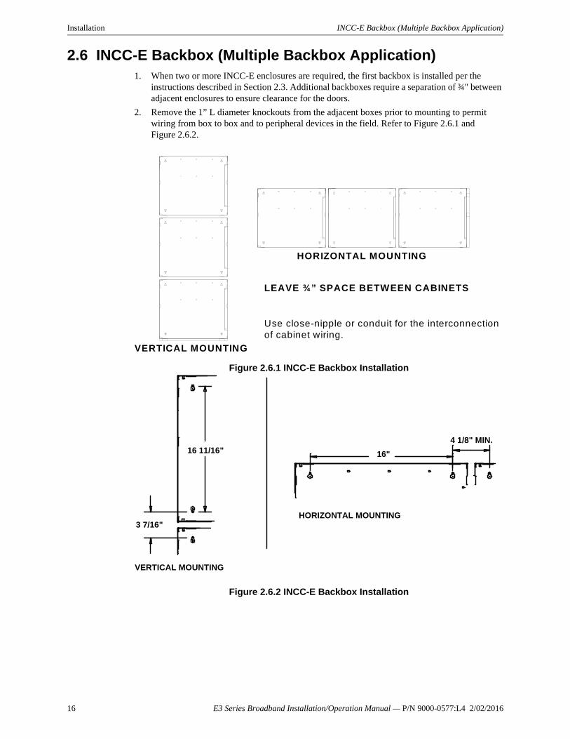
2.6 INCC-E Backbox (Multiple Backbox Application)1. When two or more INCC-E enclosures are required, the first backbox is installed per the
instructions described in Section 2.3. Additional backboxes require a separation of ¾" between adjacent enclosures to ensure clearance for the doors.
2. Remove the 1” L diameter knockouts from the adjacent boxes prior to mounting to permit wiring from box to box and to peripheral devices in the field. Refer to Figure 2.6.1 and Figure 2.6.2.
Figure 2.6.1 INCC-E Backbox Installation
Figure 2.6.2 INCC-E Backbox Installation
HORIZONTAL MOUNTING
VERTICAL MOUNTING
LEAVE ¾” SPACE BETWEEN CABINETS
Use close-nipple or conduit for the interconnection of cabinet wiring.
HORIZONTAL MOUNTING
VERTICAL MOUNTING
4 1/8" MIN.
16"
3 7/16"
16 11/16"
16 E3 Series Broadband Installation/Operation Manual — P/N 9000-0577:L4 2/02/2016
E3 Series Classic Intelligent Network Command Center Assembly Installation
2.7 E3 Series Classic Intelligent Network Command Center Assembly
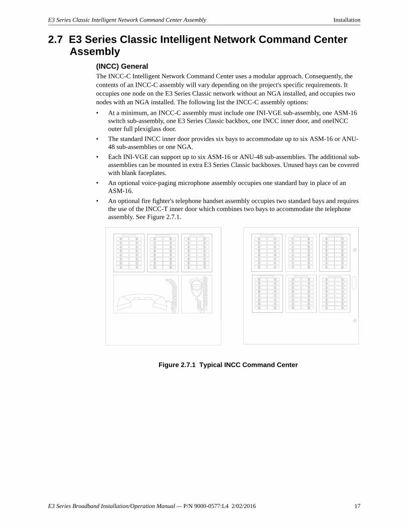
(INCC) GeneralThe INCC-C Intelligent Network Command Center uses a modular approach. Consequently, the contents of an INCC-C assembly will vary depending on the project's specific requirements. It occupies one node on the E3 Series Classic network without an NGA installed, and occupies two nodes with an NGA installed. The following list the INCC-C assembly options:
• At a minimum, an INCC-C assembly must include one INI-VGE sub-assembly, one ASM-16 switch sub-assembly, one E3 Series Classic backbox, one INCC inner door, and oneINCC outer full plexiglass door.
• The standard INCC inner door provides six bays to accommodate up to six ASM-16 or ANU-48 sub-assemblies or one NGA.
• Each INI-VGE can support up to six ASM-16 or ANU-48 sub-assemblies. The additional sub-assemblies can be mounted in extra E3 Series Classic backboxes. Unused bays can be covered with blank faceplates.
• An optional voice-paging microphone assembly occupies one standard bay in place of an ASM-16.
• An optional fire fighter's telephone handset assembly occupies two standard bays and requires the use of the INCC-T inner door which combines two bays to accommodate the telephone assembly. See Figure 2.7.1.
.
Figure 2.7.1 Typical INCC Command Center
E3 Series Broadband Installation/Operation Manual — P/N 9000-0577:L4 2/02/2016 17
Installation E3 Series Classic Intelligent Network Command Center Assembly
2.7.1 Intelligent Network Interface (INI-VGE)
1. Unpack the INI-VGE sub-assembly from its shipping carton and remove it from its anti-static bag. Locate the six mounting standoffs at the top center of the INCCE backbox. Use the six screws provided to secure the sub-assembly to the backbox at each corner, top center, and bottom center.
2. Position the sub-assembly so that the component side is facing up. The four ST fiber-optic cables are positioned to the lower left, and the four 4-pin terminal blocks run down the right side of the board.For additional information on the INI-VGE, refer to the INI-VG Series Installation Instructions P/N 9000-0549.
2.7.2 Inner Door (INCC)For information on the installation of the INCC inner door, refer to the following documents:
• E3 Series Cabinets B, C, D, Retrofit, DR-C4/DR-D4 & EQ Cabinets Installation Instructions, P/N:LS10082-000GF-E
• E3 Series, Remote Annunciator Display and Retrofit Cabinets Installation Instructions, P/N: LS10083-000GF-E
• INCC Installation Instructions, P/N 9000-0546.
2.7.3 Addressable Switch Sub-assembly (ASM-16)
1. Unpack the ASM-16 sub-assembly from its shipping carton.
2. It is recommended that the switch label be prepared and inserted between the ASM-16 faceplate overlay and the backplate at this time. Any subsequent alterations to the switch labels will require the ASM-16 to be removed from the inner door assembly to gain access to the label.
3. Place the ASM-16 sub-assembly in position in the desired location in the inner door.4. Fasten the sub-assembly in place by installing a Kep nut over the mounting studs located at
each corner. Do not tighten the nuts until all adjacent assemblies have been set in place.
For additional information on the ASM-16, refer to the ASM-16 Installation Instructions P/N 9000-0550.
5. Plug the RS-485 interconnect ribbon cable into the INI-VGE sub-assembly Connector J3. Plug the other end of the ribbon cable into J2 of the first ASM-16.Continue connecting the RS-485 bus between each additional ASM-16 as needed.
6. Extend the connection of the RS-485 bus as needed to sub-assemblies in adjoining expansion cabinets.
! CAUTION: STATIC SENSITIVE EQUIPMENTTHIS SUB-ASSEMBLY IS A STATIC SENSITIVE ELECTRONIC DEVICE. TO MINIMIZE THE POSSIBILITY OF DAMAGE, ALWAYS USE A GROUNDED WRIST STRAP OR MAINTAIN CONTACT WITH GROUND WHILE HANDLING THIS EQUIPMENT.
NOTE: The term, INI-VG Series, refers to the models: INI-VGC, INI-VGE and INI-VGX.
! CAUTION: STATIC SENSITIVE EQUIPMENTTHIS SUB-ASSEMBLY IS A STATIC SENSITIVE ELECTRONIC DEVICE. TO MINIMIZE THE POSSIBILITY OF DAMAGE, ALWAYS USE A GROUNDED WRIST STRAP OR MAINTAIN CONTACT WITH GROUND WHILE HANDLING THIS EQUIPMENT.
NOTE: For new installations, temporarily remove the INCC inner door from the INCC-E backbox and place the sub-assembly face down on a flat surface.
18 E3 Series Broadband Installation/Operation Manual — P/N 9000-0577:L4 2/02/2016

E3 Series Classic Intelligent Network Command Center Assembly Installation
2.7.4 ASM-16 or ANU-48 Wiring Connections For the ASM-16, ANU-48, INI-VG Series, ILI-MB-E3/ILI95-MB-E3, LCD-E3, LCD-SLP or remote enclosure installations, use the wiring connections in Table 2.7.4.1, and refer to Notes A-F in Figure 2.7.4.1 for the ribbon cable and hardwire locations.
NOTE: For wiring details, see the ASM-16/ ANU-48 Wiring Connections (Table 2.7.4.1 and Figure 2.7.4.1).
ASM-16 or ANU-48 to ASM-16 or ANU-48 Wiring
Designation Description Designation From ASM-16 or ANU-48 Ribbon Cable To ASM-16 or ANU-48 J1 Ribbon Cable Connect To:
J1 LCD-E3 J1,J2 ANU-48 J3 INI-VGC, INI-VGX, INI-VGE J1,J2,J3
ASM-16
J2 Ribbon Cable Connect To: J1 LCD-E3 J1,J2 ANU-48 J3 INI-VGC, INI-VGX, INI-VGE J1,J2,J3
ASM-16
J3 Ribbon Cable Connect To: J1 LCD-E3 J1,J2 ANU-48 J3 INI-VGC, INI-VGX, INI-VGE J1,J2,J3
ASM-16
J4 Emulator Factory Use Only J5 Factory Use OnlyJMP1 Termination Install Jumper only if the last device is on
RS-485 bus.
NOTE: See Note A in Figure 2.7.4.1 for the ribbon cable connection.
ASM-16 or ANU-48 to ASM-16 or ANU-48 Wiring
From ASM-16 or ANU-48 RS-485 COM A from previous device/to next device. Connect To:
TB1-1 COMM A Single Discrete Wire TB3-1 ILI-MB-E3/ILI95-MB-E3
TB6-3 INI-VGC, INI-VGX, INI-VGE
TB1-3 DACT-E3
TB1-1 ASM-16, ANU-48
TB1-5 LCD-E3
TB1-1 LCD-SLP
TB1-1 LCD-7100/RAN-7100
TB1-2 COMM B Single Discrete Wire RS-485 COM B from previous device/to next device. Connect To:
TB3-2 ILI-MB-E3/ILI95-MB-E3
TB6-2 INI-VGC, INI-VGX, INI-VGE
TB1-4 DACT-E3
TB1-2 ASM-16, ANU-48
TB1-6 LCD-E3
TB1-2 LCD-SLP
TB1-2 LCD-7100/RAN-7100
TB1-3 +24V Single Discrete Wire Connect To:
TB1-3 +24V
TB3-6 ILI-MB-E3/ILI95-MB-E3
TB6-1 INI-VGC, INI-VGX, INI-VGE
Table 2.7.4.1 ASM-16 or ANU-48 Wiring Connections
E3 Series Broadband Installation/Operation Manual — P/N 9000-0577:L4 2/02/2016 19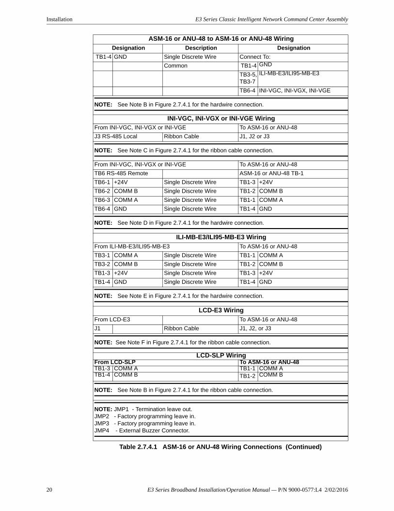
Installation E3 Series Classic Intelligent Network Command Center Assembly
ASM-16 or ANU-48 to ASM-16 or ANU-48 Wiring
Designation Description Designation
TB1-4 GND Single Discrete Wire Connect To:
Common TB1-4 GND
TB3-5, TB3-7
ILI-MB-E3/ILI95-MB-E3
TB6-4 INI-VGC, INI-VGX, INI-VGE
NOTE: See Note B in Figure 2.7.4.1 for the hardwire connection.
INI-VGC, INI-VGX or INI-VGE WiringFrom INI-VGC, INI-VGX or INI-VGE To ASM-16 or ANU-48
J3 RS-485 Local Ribbon Cable J1, J2 or J3
NOTE: See Note C in Figure 2.7.4.1 for the ribbon cable connection.
From INI-VGC, INI-VGX or INI-VGE To ASM-16 or ANU-48
TB6 RS-485 Remote ASM-16 or ANU-48 TB-1
TB6-1 +24V Single Discrete Wire TB1-3 +24V
TB6-2 COMM B Single Discrete Wire TB1-2 COMM B
TB6-3 COMM A Single Discrete Wire TB1-1 COMM A
TB6-4 GND Single Discrete Wire TB1-4 GND
NOTE: See Note D in Figure 2.7.4.1 for the hardwire connection.
ILI-MB-E3/ILI95-MB-E3 Wiring
From ILI-MB-E3/ILI95-MB-E3 To ASM-16 or ANU-48
TB3-1 COMM A Single Discrete Wire TB1-1 COMM A
TB3-2 COMM B Single Discrete Wire TB1-2 COMM B
TB1-3 +24V Single Discrete Wire TB1-3 +24V
TB1-4 GND Single Discrete Wire TB1-4 GND
NOTE: See Note E in Figure 2.7.4.1 for the hardwire connection.
LCD-E3 Wiring
From LCD-E3 To ASM-16 or ANU-48
J1 Ribbon Cable J1, J2, or J3
NOTE: See Note F in Figure 2.7.4.1 for the ribbon cable connection.
LCD-SLP WiringFrom LCD-SLP To ASM-16 or ANU-48TB1-3 COMM A TB1-1 COMM ATB1-4 COMM B TB1-2 COMM B
NOTE: See Note B in Figure 2.7.4.1 for the ribbon cable connection.
NOTE: JMP1 - Termination leave out.JMP2 - Factory programming leave in.JMP3 - Factory programming leave in.JMP4 - External Buzzer Connector.
Table 2.7.4.1 ASM-16 or ANU-48 Wiring Connections (Continued)
20 E3 Series Broadband Installation/Operation Manual — P/N 9000-0577:L4 2/02/2016

E3 Series Classic Intelligent Network Command Center Assembly Installation
Figure 2.7.4.1 illustrates the ASM-16 and ANU-48 wiring connections.
Figure 2.7.4.1 ASM-16 and ANU-48 Wiring Connections
J1 J2
J3
J2J1
J1 J2
J1 J2 J1 J2
NOTE C and F: From local INI-VG or LCD-E3 J1 (RS-485 Local)
NOTE B, D and E:HARDWARE RS-485 Port(to/from module in different INCC cabinet)From ILI-MB-E3/ILI95-MB-E3 TB3-1, TB3-2, TB1-3, and TB1-4From SLP-E3 TB2-3, TB2-4, TB3-1, TB3-2
RS-485 RIBBON CABLEConnector (to/from modulein same INCC cabinet)
NOTE B:To next ASM-16 or ANU-48 TB1 remote in next INCC cabinet or to LCD-SLP
J3
TB1REMOTE
TB1REMOTE
TB1REMOTE
TB1REMOTE
TB1REMOTE
SW17 SW17 SW17
SW17 SW17
TB1REMOTE
JMP1 JMP1 JMP1
JMP1JMP1JMP1
J3
J3 J3 J3
A
A
NOTE A:ASM-16 or ANU-48 to ASM-16 or ANU-48 wiringASM-16/ANU-48 to ASM-16/ANU-48 RS-485 connection
A
A
A
A
J1 J2
B
BDE
CFA A
AA
NOTE A:ASM-16 or ANU-48 to ASM-16 or ANU-48 wiringASM-16/ANU-48 to ASM-16/ANU-48 RS-485 connection
NOTE A:ASM-16 or ANU-48 to ASM-16 or ANU-48 wiringASM-16/ANU-48 to ASM-16/ANU-48 RS-485 connection
E3 Series Broadband Installation/Operation Manual — P/N 9000-0577:L4 2/02/2016 21
Installation E3 Series Classic Intelligent Network Command Center Assembly
2.7.5 Remote LED Driver Sub-Assembly (ANU-48)
1. Unpack the ANU-48 sub-assembly from its shipping carton. Remove the unit from its static-shielded bag, observing proper static protection measures.
2. Place the ANU-48 sub-assembly in position in the desired location in the inner door.
3. To fasten the assembly in place, install the nuts (provided with the Hardware Kit) over the mounting studs located at each corner. Do not tighten the nuts until all adjacent assemblies have been set in place.
For additional information on the ANU-48, refer to the ANU-48 Installation Instructions P/N 9000-0564.
4. Plug the RS-485 interconnect ribbon cable into the INI-VG Series sub-assembly connector J3. Plug the other end of the ribbon cable into J1 of the first ANU-48.
Install the ribbon cables from J2 of the first ANU-48 board to J1 of the next, and continue.
5. Extend the RS-485 bus as needed to sub-assemblies in adjoining expansion cabinets.
NOTE 1: For wiring details, see the ASM-16 and ANU-48 Wiring Connections (Table 2.7.4.1 and Figure 2.7.4.1).
NOTE 2: The annunciator may be located up to 3,000 feet from the panel and up to three additional annunciators can be connected, configured identically with the first. See Table 2.7.5.1 for resistance limitations for the connecting circuit.
NOTE 3: If more than four ANU-48 modules are installed, an external regulated and Class 2 power-limited, power supply Listed for use with fire protective signaling units is required.
! CAUTION: STATIC SENSITIVE EQUIPMENTTHIS SUB-ASSEMBLY IS A STATIC SENSITIVE ELECTRONIC DEVICE. TO MINIMIZE THE POSSIBILITY OF DAMAGE, ALWAYS USE A GROUNDED WRIST STRAP OR MAINTAIN CONTACT WITH GROUND WHILE HANDLING THIS EQUIPMENT.
NOTE: For new installations, temporarily remove the INCC Inner Door from the INCC-E backbox and place it face down on a flat surface.
Quantity of ANU-48 Modules 1 2 3 4
Maximum resistance of 24 VDC power circuit (ohms) to most distant ANU-48
40 20 14 10
Table 2.7.5.1 ANU-48 Resistance Limitations
22 E3 Series Broadband Installation/Operation Manual — P/N 9000-0577:L4 2/02/2016

E3 Series Classic Intelligent Network Command Center Assembly Installation
2.7.6 Amplifiers (AA-100, AA-120)The AA-100 and AA-120 amplifiers mount in the cabinets DR-C4B and DR-D4B. Unpack the AA Amplifier from its shipping carton and remove it from its anti-static bag. It mounts directly in the DR cabinet.
2.7.7 Cabinet (s) DR-C4B, DR-D4BThe amplifier cabinets can house three or four AA-100 or AA-120 amplifiers. These amplifiers can be configured as one, two, or three main amplifiers with or without a common shared redundant standby amplifier. They can also be configured as two primary amplifiers, where each primary amplifier has its own standby amplifier.
Figure 2.7.7.1 Cabinet DR-C4B
Figure 2.7.7.2 Cabinet DR-D4B
dia. dia.
E3 Series Broadband Installation/Operation Manual — P/N 9000-0577:L4 2/02/2016 23

Installation E3 Series Classic Intelligent Network Command Center Assembly
2.7.8 Voice Paging Microphone Assembly (Optional)1. Unpack the pre-assembled Voice Paging Microphone assembly from its shipping carton.
2. The Microphone assembly occupies one bay of the inner door. Place the Microphone assembly in position in the desired location in the inner door.
3. To fasten the assembly in place, install a Kep nut (provided in the Hardware Kit) over the mounting studs located at each corner.
4. Remove the jumpers that are installed on the INI-VGE J15 header.
5. Connect the six-pin connector of the coiled cord to J15 on the INI-VGE, labeled "Microphone".
Figure 2.7.8.1 Voice Paging Microphone Assembly
NOTE: For new installations, temporarily remove the INCC inner door from the INCC-E backbox and place it face down on a flat surface.
NOTE: Do not tighten the nuts until all adjacent assemblies have been set in place.
NOTE: Be sure to position the connector so that the gray jumper spans the top two pins on the INI-VGE J15 (Pins 6 and 5 counting from the top down). See Figure 2.7.8.1 for details.
Remove Jumpers from INI-VGEConnector J15
Gray Jumper
Microphone Cable
INI-VGE
J15
MIC
RO
PH
ON
E
TB2
TB4
SD
A/S
CL
LO
OP
J15
MIC
RO
PH
ON
E
W5
J4
NOTE:IF NO MICROPHONE IS INSTALLED, INSTALL JUMPERS BETWEENPINS 3 AND 4, AND 5 AND 6.
24 E3 Series Broadband Installation/Operation Manual — P/N 9000-0577:L4 2/02/2016

E3 Series Classic Intelligent Network Command Center Assembly Installation
2.7.9 Fire Fighter's Intercom Handset Assembly (Optional)1. Unpack the handset assembly from its shipping carton.
2. The handset assembly occupies two bays of the inner door. Place the handset assembly in position on the inner door.
3. To fasten the assembly in place, install a Kep nut over the mounting studs located at each corner. Do not tighten the nuts until all adjacent assemblies have been set in place.
4. Plug the pre-assembled four-pin terminal block that terminates the phone cable into the INI-VGE TB5.
5. Remove INI-VGE jumper W5 to enable local handset connection. See Figure 2.7.9.1.
Figure 2.7.9.1 Fire Fighter’s Intercom Handset Assembly
NOTE: Be sure to use the INCC-T inner door to accommodate the assembly. For new installations, temporarily remove the inner door from the INCC-E backbox and place it face down on a flat surface.
INI-VGE
NOTE 1:When the INI-VGE terminalblock TB5 is connected to alocal handset, it cannot be used as a phone riser, connected to remote AOM-TELFs.
NOTE 2:Install the jumper between TB5-3and TB5-4, if the INI-VGEFirmware is V2.0-006 or later.
Remove Jumper W5 toenable local handset
connection
Telephone Cable
TB2
TB4
TB5
W5
W5
LO
OP
J4
Supervisory Jumper
E3 Series Broadband Installation/Operation Manual — P/N 9000-0577:L4 2/02/2016 25
Installation E3 Series Classic Intelligent Network Command Center Assembly
2.7.10 NGA LCD Annunciator Sub Assembly
1. Unpack the NGA sub-assembly from its shipping carton. Remove the unit from its static-shielded bag, observing proper static protection measures. For new installations, temporarily remove the INCC inner door from the INCC-E backbox and place it face down on a flat surface.
2. Place the NGA sub-assembly in position in the upper left opening in the inner door.
3. To fasten the assembly in place, install the nuts (provided with the Hardware Kit) over the mounting studs located at each corner.
4. Plug the ARCNET interconnect ribbon cable into the INI-VG Series sub-assembly connector J7.
Alternatively, the NGA may be connected to the network via the RPT-E3-UTP.
For additional information, refer to the following documents:
– E3 Series Broadband Installation/Operation Manual, P/N 9000-0575
– NGA Installation Instructions, P/N 9000-0568
5. Plug the other end of the ribbon cable into J4 of the NGA.
! CAUTION: STATIC SENSITIVE EQUIPMENTTHIS SUB-ASSEMBLY IS A STATIC SENSITIVE ELECTRONIC DEVICE. TO MINIMIZE THE POSSIBILITY OF DAMAGE, ALWAYS USE A GROUNDED WRIST STRAP OR MAINTAIN CONTACT WITH GROUND WHILE HANDLING THIS EQUIPMENT.
NOTE: Do not tighten the nuts until all adjacent assemblies have been set in place.
! CAUTION: WIRING RESTRICTIONDO NOT CONNECT TO J3!
26 E3 Series Broadband Installation/Operation Manual — P/N 9000-0577:L4 2/02/2016

E3 Series Classic Intelligent Network Command Center Assembly Installation
Notes
E3 Series Broadband Installation/Operation Manual — P/N 9000-0577:L4 2/02/2016 27

Section 3: Wiring
3.1 Power ConnectionsConnection of the power supply to the 120 @ 60 Hz or 240 VAC @ 50/60 Hz power source must be made in compliance with the National Electrical Code, NFPA 70, Article 760, the applicable NFPA Standards, and according to the requirements of the Authority Having Jurisdiction. Such requirements include:
• Connections must be made to a dedicated branch circuit.
• Connections must be mechanically protected.
• All means of disconnecting the circuit must be clearly marked:
"FIRE ALARM CIRCUIT CONTROL".
• Connections must be accessible only to authorized personnel.
!WARNING: EARTH GROUND REQUIREMENT USE A COLD WATER PIPE OR A GROUND-DRIVEN ROD TO ENSURE PROPER BONDING. PANEL NEUTRAL OR CONDUIT GROUND ARE NOT ACCEPTABLE. USE 14 AWG MIN. WIRE.
28 E3 Series Broadband Installation/Operation Manual — P/N 9000-0577:L4 2/02/2016

Intelligent Network Interface, Voice Gateway (INI-VGE) Wiring
3.2 Intelligent Network Interface, Voice Gateway (INI-VGE)The INI-VGE is the network interface sub-assembly for the INCC-C, E3 Series® Classic Voice Command Center.
In the INCC enclosure, the INI-VGE sub-assembly connects to the E3 Series Classic System microphone and fire fighter telephone handset, and supervises and controls up to six ANU-48 or ASM-16 sub-assemblies. Figure 3.2.1 shows all the available connections on the INI-VGE and their functions.
The INI-VGE Series also has one Signaling Line Circuit (SLC) wired Style 4 (Class "B") only. This SLC supports up to sixteen AOM-TELF fire fighter intercom circuits and up to thirty-two AOM-2SF (single-channel, speaker circuits). The MMO-6SF six-circuit single-channel, speaker circuits modules are also supported, but each MMO-6SF takes up six addresses on the SLC. Optionally, one NGA, up to six ASM-16/ANU-48 modules may be used with the INI-VGX.
Figure 3.2.1 Typical Connections to the INI-VGE
Connect a ground wire from the INI-VGE TB3 Terminal 1.
The INI-VGE has only one signaling line circuit (SLC) wired Style 4 (Class "B"). This SLC supports up to sixteen AOM-TELF Fire Fighter intercom circuits and up to thirty-two AOM-2SF single-channel speaker circuits.** Connection must be in the same room, close-nippled or in a rigid conduit not over 20 feet long.
NOTE 2:IF NO MICROPHONE IS INSTALLED,INSTALL JUMPERS BETWEEN PINS3 & 4 AND 5 & 6.
NOTE 3:INSTALL THE JUMPER BETWEEN TB5-3 AND TB5-4 ON THE INI-VG SERIES WHEN THE FIRMWARE IS V2.0-006 OR LATER.
(CL
EA
R)
(BL
AC
K)
TB1
TB3
EG
ND1
4
W3EGND
J2
J5
J6
J8
SW1
J11214
13
J16SIGNALS IN/OUT
12
1920
J7REPEATER
SDA
/SCL
21 9
10
J4
1 2
9
10
RS485 LOCAL12
910
J3
W2TERM
RS485 REMOTESEE NOTE 4:
TB6
14
1
4
TB5
TB4
TB2
LO
OP
W5
PH
ON
E
J15
MIC
RO
PH
ON
E 1
6
1
14
4
CHANNEL 2
CHANNEL 1
RX2
TX2
RX1
TX1
TO ASM-16 TB1-3 OR ANU-48 TB1-3 (+)TO ASM-16 TB1-2 OR ANU-48 TB1-2 (RS485 COM B)TO ASM-16 TB1-1 OR ANU-48 TB1-1 (RS485 COM A)
TO ASM-16 TB1-4 OR ANU-48 TB1-4 (-)
LED3MRCLED5TXLED7RX2LED9DG
LED1RECLED4DUP
LED6RX1
LED8RST
NetSOLO® CONNECTIONSUSING WIRE UNSHIELDED, TWISTED-PAIR
NetSOLO® CONNECTIONSUSING FIBER-OPTIC CABLE(STANDARD ST CONNECTORS)
COM 1ACOM 1BCOM 2ACOM 2B
NODE COM 2ANODE COM 2BNODE COM 1ANODE COM 1B
TONEXT
NODE RX2CONNECTORNODE TX2CONNECTORNODE RX1CONNECTORNODE TX1CONNECTOR
FROMPREVIOUS
FROMPREVIOUS
TONEXT
“E” FNCTNS\RESET
GND ( - ) 24 VDC + OUTGND ( - )24 VDC + IN
TO SIGNALING LINE CIRCUIT (-) TO SIGNALING LINE CIRCUIT (+)TO ACT-2 ( + ) TERMINALTO ACT-1 ( - ) TERMINAL
DISTANCE BETWEENINI-VGE AND ACT-1NOT TO EXCEED20 FEET MAX.
JUMPER16 AWG (FIREFIGHTER PHONE SUPERVISORY)
TO AOM-TELF(S) TERM 4TO AOM-TELF(S) TERM 3
CONNECTIONSFROM TELEPHONE
TELEPHONE BOX OR TERMINAL BLOCK
OFF
-+ G
ND
HK
BLACKWHITEREDWHITENOTE 1:
LED1 = REC (NETWORK CONFIGURATION)LED3 = MRC NETWORK RECONFIGURATION ORIGINATING FROM THIS NODELED4 = DUP (NODE’S NETWORK ADDRESS IS DUPLICATED AT ANOTHER NODE)LED5 = TX (NODE IS TRANSMITTING DATA TO THE NETWORK)LED6 = RX1 (NODE IS RECEIVING DATA FROM THE NETWORK)LED7 = RX2 (NODE IS RECEIVING DATA FROM THE NETWORK)LED8 = RST (FIRMWARE FAULT)LED9 = DG (GENERAL NETWORK FAULT)
SEE NOTE 1: SEE NOTE 2:
SEE NOTE 3:
NOTE 4:EITHER THE RS-485 LOCAL OR RS-485 REMOTE CONNECTION MAY BE USED. DO NOT USE BOTH.
TO NGA J4OR ILI-E3 J4
W1
W4
GFI
CONFIG
E3 Series Broadband Installation/Operation Manual — P/N 9000-0577:L4 2/02/2016 29

Wiring Intelligent Network Interface, Voice Gateway (INI-VGE)
3.2 Intelligent Network Interface, Voice Gateway (INI-VGE) (Continued)
Table 3.2.1 lists the E3 Series Classic INI-VGE Power Consumption Calculation Chart.
Qty Sub-Assembly Description Supv.
Current Alarm
Current Total
Supv. Current
TotalAlarm
Current
INI-VGE Intelligent Network Voice Gateway-Command Center
0.150 A 0.150 A
ASM-16 Addressable Switch Sub-assembly
0.011 A (See Note 2)
0.011 A (See Note 2)
ANU-48 Remote LED Driver 0.011 A (See Note 1)
0.011 A (See Note 1)
NGA Network Graphic Annunciator
0.200 A
(See Note 3)0.200 A(See Note 3)
Microphone Paging Microphone 0.001 A 0.001 A
Telephone Fire Fighter's Telephone Handset
0.020 A 0.020 A
AOM-TELF Addressable Output Module-Telephone
0.0024 A 0.0075 A
AOM-2SF Addressable Output Module 0.000375 A Velociti
0.0065 A
MMO-6SF Addressable Output Module 0.00225 A 0.035 A
Total:
NOTES:
The total supervisory and alarm currents determined in the above columns must be added to the standby battery calculations for the power supply providing the operating voltage to the INCC-C. Typically, this is a PM-9/PM-9G or UL Listed fire power supply.
NOTE 1: Add 0.003 A for each LED that is programmed to be lit for trouble or supervisory off-normal conditions.
NOTE 2: Add 0.003 A for each LED that is programmed to be lit for alarm conditions.
NOTE 3: Normal operating current. During a power failure, the current drops to 0.045 amp since backlight is extinguished.
Table 3.2.1 E3 Series Classic INI-VGE Power Consumption Calculation Chart
30 E3 Series Broadband Installation/Operation Manual — P/N 9000-0577:L4 2/02/2016

Intelligent Network Interface, Voice Gateway (INI-VGE) Wiring
E3 Series Broadband Installation/Operation Manual — P/N 9000-0577:L4 2/02/2016 31
3.2 Intelligent Network Interface, Voice Gateway (INI-VGE) (Continued)Table 3.2.2 lists the E3 Series Classic INI-VGE Series field wiring connections.
Terminal Block 1- E3 Series Classic Network connection- using unshielded, twisted-pair
TB1-1 COM 1A connection
TB1-2 COM 1B connection
TB1-3 COM 2A connection
TB1-4 COM 2B connection
Terminal Block 2- External Power Connection (INI-VGE)
TB2-1 24 VDC ( + ) power input from external power supply or PM-9/PM-9G TB4-5
TB2-2 GND ( - ) power input from external power supply or PM-9/PM-9G TB4-2
TB2-3 24 VDC ( + ) Power Out terminal-wiring terminal only, not a source of power
TB2-4 GND Power Out terminal-wiring terminal only, not a source of power
TB3-1 Earth Ground
Terminal Block 4- Power Amplifier and Signaling Line Circuit Connections (See Notes 1, 2 and 3)
TB4-1 Local Speaker (INCC, INX or INX CAB-B only) or Connect to ACT-1 (-) Terminal (INI-VGE only)
TB4-2 Local Speaker (INCC, INX or INX CAB-B only) or Connect to ACT-2 (+) Terminal (INI-VGE Only)
TB4-3 Signaling Line Circuit ( + ), Style 4, Class "B"
TB4-4 Signaling Line Circuit ( - ), Style 4, Class "B"
Terminal Block 5- Fire Fighter Handset or Fire Fighter Phone riser connection(INI-VGE)
TB5-1 Fire Fighter Phone ( - ): Plugs into local Fire Fighter Handset- INI-VGC Phone riser field wire connection to AOM-TELF Term 3 - INI-VGX and INI-VGE
TB5-2 Fire Fighter Phone ( + ): Plugs into local Fire Fighter Handset- INI-VGC Phone riser field wire connection to AOM-TELF Term 4 - INI-VGX and INI-VGE
TB5-3 Telephone Plug Supervisory Loop (Connects to TB5-4). Connect only if INI-VGE Firmware is V2.0-006 or later.
TB5-4 Telephone Plug Supervisory Loop (Connects to TB5-3). Connect only if INI-VGE Firmware is V2.0-006 or later.
Terminal Block 6- RS485 Remote Communication Connection to ASM-16 or ANU-48 in Separate Cabinet
TB6-1 + 24 VDC Supply - connects to remote ASM-16 or ANU-48 TB1-3
TB6-2 RS-485 COM B - connects to remote ASM-16 or ANU-48 TB1-2
TB6-3 RS-485 COM A - connects to remote ASM-16 or ANU-48 TB1-1
TB6-4 System Common ( - ) connects to remote ASM-16 or ANU-48 TB1-4
NOTE 1: INI-VGC Signaling Line Circuit supports AOM-TEL and AOM-TELF Telephone Modules.
NOTE 2: INI-VGX Signaling Line Circuit supports AOM-TEL and AOM-TELF Telephone Modules and AOM-2S, AOM-2SF, MMO-6S, MMO-6SF Speaker Circuit Control Modules.
NOTE 3: INI-VGE Signaling Line Circuit supports AOM-TEL, AOM-2SF, and MMO-6SF Control Modules.
Table 3.2.2 E3 Series Classic INI-VGE Field Wiring Connections

Wiring Intelligent Network Interface, Voice Gateway (INI-VGE)
3.2 Intelligent Network Interface, Voice Gateway (INI-VGE) (Continued)Table 3.2.3 lists the E3 Series Classic INI-VGE jumpers and cable connections. Table 3.2.4 lists the E3 Series Classic INI-VGE indicating and diagnostic LEDs.
Designation Description Comments
J1 "E" FNCTNS/RESET Factory use
J2 Fiber-Optic ST Channel 1 TX1 Connects to next node RX2 ST connector
J3 RS-485 Local Connects to 1st Local ASM-16/ANU-48 Connector J2
J4 SDA/SCL Connects to PM-9/PM-9G Connector J1-INX or INX CAB-B
J5 Fiber-Optic ST Channel 1 RX1 Connects to next node TX2 ST connector
J6 Fiber-Optic ST Channel 2 TX2 Connects form previous node RX1 connector
J7 Repeater Network Backplane. Connect to J4 on NGA sub-assembly (optional) or J4 on ILI-E3 Series or ANX (optional).For optimum network communication, run this cable underneath PM-9/PM-9G.
J8 Fiber-Optic ST Channel 2 RX2 Connects from previous node TX1 connector
J15 Microphone Connectors to microphone cableIf no microphone is installed, jumpers must be installed between pins 3 and 4, and 5 and 6.
J16 Signals In/Out Connects to the 1st AM-50 Series amplifier connector J1 INX or INX CAB-B only(See Note 1)
W1 GFI Switch IN for ground fault indicationInstall the jumper to supervise for ground faults on the network wiring between this INI-VGE and any other nodes that are directly connected to this INI-VGE.
W2 Termination Switch Install the jumper to supervise for ground faults on the network wiring between this INI-VGE and any other nodes that are directly connected to this INI-VGE.
W3 EGND Switch IN to enable earth ground reference circuitJumper should only be installed if the INI-VG is powered by a power supply that does NOT supervise for ground faults.
W4 Config Switch Factory Use. Do not install.
W5 Handset Enable Switch OUT to enable Local Fire Fighter Handset connectionIN to enable Phone Riser connection to AOM-TELFs
NOTE: Connections must be in the same room, close-nippled or in rigid conduit, not to exceed 20 feet.
Table 3.2.3 E3 Series Classic INI-VGE Jumpers & Cable Connections
NOTE 1: The term, AM-50 Series refers to the models: AM-50-25 and AM-50-70 amplifiers.
32 E3 Series Broadband Installation/Operation Manual — P/N 9000-0577:L4 2/02/2016

Intelligent Network Interface, Voice Gateway (INI-VGE) Wiring
Designation Description Comments
LED 1- REC A network reconfiguration is in progress.
LED 3- MRC This node is attempting to perform a network reconfiguration.
LED 4- DUP Duplicate or invalid network address.
LED 5- TX The sub-assembly is transmitting network data.
LED 6- RX1 This sub-assembly is receiving network data on Channel 1.
LED 7- RX2 The sub-assembly is receiving network data on Channel 2.
LED 8- RST Firmware fault.
LED 9- DG GENERAL NETWORK FAULT
Table 3.2.4 E3 Series Classic INI-VGE Indicating and Diagnostic LEDs
E3 Series Broadband Installation/Operation Manual — P/N 9000-0577:L4 2/02/2016 33

Wiring Intelligent Network Interface, Voice Gateway (INI-VGE)
3.2.1 INI-VGE Power Connections
The INI-VGE-FO or INI-VGE-UTP serving as the network interface and control unit of an INCC-C Command Center connects to its operating power via Terminal Block TB2. Figure 3.2.1.1 illustrates the INI-VGE power connections.
Figure 3.2.1.1 INI-VGE Power Connection
NOTE 2:IF NO MICROPHONE IS INSTALLED,INSTALL JUMPERS BETWEEN PINS3 & 4 AND 5 & 6.
NOTE 3:INSTALL THE JUMPER BETWEEN TB5-3 AND TB5-4 ON THE INI-VG SERIES WHEN THE FIRMWARE IS V2.0-006 OR LATER.
(CL
EA
R)
(BL
AC
K)
TB1
TB3
EG
ND1
4
W3EGND
J2
J5
J6
J8
SW1
J11214
13
J16SIGNALS IN/OUT
12
1920
J7REPEATER
SDA
/S CL
21 9
10
J4
1 2
9
10
RS485 LOCAL12
910
J3
W2TERM
RS485 REMOTESEE NOTE 4:
TB6
14
1
4
TB5
TB4
TB2
LO
OP
J15M
ICR
OP
HO
NE 1
6
1
14
4
CHANNEL 2
CHANNEL 1
RX2
TX2
RX1
TX1
TO ASM-16 TB1-3 OR ANU-48 TB1-3 (+)TO ASM-16 TB1-2 OR ANU-48 TB1-2 (RS485 COM B)TO ASM-16 TB1-1 OR ANU-48 TB1-1 (RS485 COM A)
TO ASM-16 TB1-4 OR ANU-48 TB1-4 (-)
LED3MRCLED5TXLED7RX2LED9DG
LED1RECLED4DUPLED6RX1
LED8RST
NetSOLO® CONNECTIONSUSING WIRE UNSHIELDED, TWISTED-PAIR
NetSOLO® CONNECTIONSUSING FIBER-OPTIC CABLE(STANDARD ST CONNECTORS)
COM 1ACOM 1BCOM 2ACOM 2B
NODE COM 2ANODE COM 2BNODE COM 1ANODE COM 1B
TONEXT
NODE RX2CONNECTORNODE TX2CONNECTOR
NODE RX1CONNECTORNODE TX1CONNECTOR
FROMPREVIOUS
FROMPREVIOUS
TONEXT
“E” FNCTNS\RESET
GND ( - ) OUT24 VDC + OUTGND ( - ) IN24 VDC + IN
TO SIGNALING LINE CIRCUIT (-) TO SIGNALING LINE CIRCUIT (+)TO ACT-2 ( + ) TERMINALTO ACT-1 ( - ) TERMINAL
DISTANCE BETWEENINI-VGE AND ACT-1NOT TO EXCEED20 FEET MAX.
JUMPER16 AWG (FIREFIGHTER PHONE SUPERVISORY)
TO AOM-TELF(S) TERM 4TO AOM-TELF(S) TERM 3
CONNECTIONSFROM TELEPHONE
TELEPHONE BOX OR TERMINAL BLOCK
OFF
-+ G
ND
HK
BLACKWHITEREDWHITENOTE 1:
LED1 = REC (NETWORK CONFIGURATION)LED3 = MRC NETWORK RECONFIGURATION ORIGINATING FROM THIS NODELED4 = DUP (NODE’S NETWORK ADDRESS IS DUPLICATED AT ANOTHER NODE)LED5 = TX (NODE IS TRANSMITTING DATA TO THE NETWORK)LED6 = RX1 (NODE IS RECEIVING DATA FROM THE NETWORK)LED7 = RX2 (NODE IS RECEIVING DATA FROM THE NETWORK)LED8 = RST (FIRMWARE FAULT)LED9 = DG (GENERAL NETWORK FAULT)
SEE NOTE 1: SEE NOTE 2:
SEE NOTE 3:
NOTE 4:EITHER THE RS-485 LOCAL OR RS-485 REMOTE CONNECTION MAY BE USED. DO NOT USE BOTH.
TO 1ST LOCAL ASM-16OR ANU-48
J2 CONNECTOR(IN SAME CABINET)
TO NGA J4 OR ILI-E3 J4
TO PM-9/PM-9G J1 CONNECTOR
W1
W4
GFI
CONFIG
W5
PH
ON
E
Description Comments
TB2-1 +24 VDC IN - from power supply
TB2-2 Common ( - ) IN - from power supply
TB2-3 +24 VDC OUT
TB2-4 Common ( - ) OUT
Table 3.2.1.1 INI-VGE Series Power Connections
34 E3 Series Broadband Installation/Operation Manual — P/N 9000-0577:L4 2/02/2016
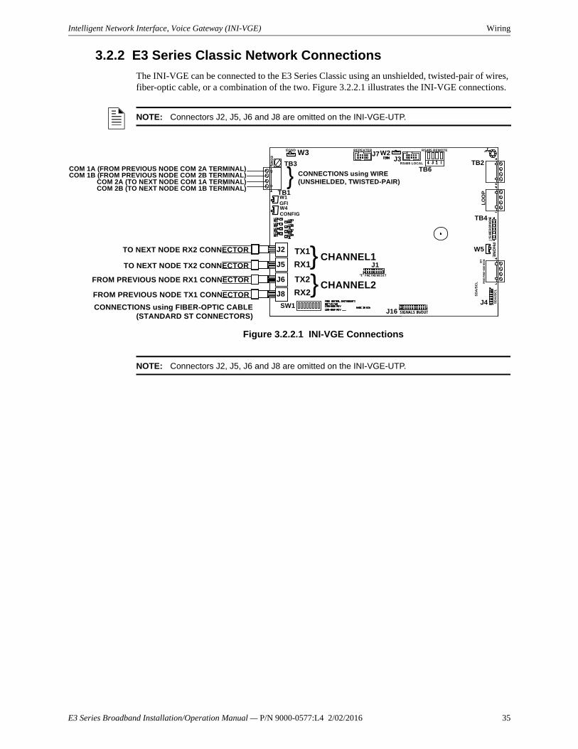
Intelligent Network Interface, Voice Gateway (INI-VGE) Wiring
3.2.2 E3 Series Classic Network Connections
The INI-VGE can be connected to the E3 Series Classic using an unshielded, twisted-pair of wires, fiber-optic cable, or a combination of the two. Figure 3.2.2.1 illustrates the INI-VGE connections.
Figure 3.2.2.1 INI-VGE Connections
NOTE: Connectors J2, J5, J6 and J8 are omitted on the INI-VGE-UTP.
NOTE: Connectors J2, J5, J6 and J8 are omitted on the INI-VGE-UTP.
{{
)
W3 J7J3
W2
TB6
REPEATER RS485 REMOTE
TB2
TB4
J15
MIC
RO
PHO
NE
LO
OP
SD
A/S
CL
SD
A/S
CL
TB3
TB1
RS485 LOCAL
OFF
PHN
E-PH
NE+
GN
D H
OO
K
J1
J2
SW1
TX2
RX2CHANNEL2
CHANNEL1TX1
RX1
TO NEXT NODE RX2 CONNECTOR
TO NEXT NODE TX2 CONNECTOR
FROM PREVIOUS NODE RX1 CONNECTOR
FROM PREVIOUS NODE TX1 CONNECTOR
CONNECTIONS using FIBER-OPTIC CABLE(STANDARD ST CONNECTORS)
CONNECTIONS using WIRE(UNSHIELDED, TWISTED-PAIR)
COM 1A (FROM PREVIOUS NODE COM 2A TERMINAL)COM 1B (FROM PREVIOUS NODE COM 2B TERMINAL)
COM 2A (TO NEXT NODE COM 1A TERMINAL)
W1GFI
COM 2B (TO NEXT NODE COM 1B TERMINAL)
J4J16 SIGNALS IN/OUT
“E” FNCTNS\RESET
EGND
EG
ND
W5
PH
ON
E
W4CONFIG
J5
J6
J8
E3 Series Broadband Installation/Operation Manual — P/N 9000-0577:L4 2/02/2016 35
Wiring Intelligent Network Interface, Voice Gateway (INI-VGE)
3.2.2 E3 Series Classic Network Connections (Continued)Designation Description Comments
TB1-1 COM 1A To next node's TB1-3 (COM 2A)
TB1-2 COM 1B To next node's TB1-4 (COM 2B)
TB1-3 COM 2A From previous node's TB1-1 (COM 1A)
TB1-4 COM 2B From previous node's TB1-2 (COM 1B)
Table 3.2.2.1 E3 Series Classic Network Wire Terminations
Description Comments
ST Connector J2 Channel 1 TX1 To next node's ST Connector J8 (RX2)
ST Connector J5 Channel 1 RX1 To next node's ST Connector J6 (TX2)
ST Connector J6 Channel 2 TX2 From previous node's ST Connector J5 (RX1)
ST Connector J8 Channel 2 RX2 From previous node's ST Connector J2 (TX1)
Fiber-optic cable: up to 200 microns (optimized for 62.5/ 125 microns)Up to 8 dB loss max. between nodes.
Table 3.2.2.2 E3 Series Classic Network Fiber-Optic Cable Connections (INI-VGE Only)
!WARNING: FIBER OPTIC CABLE RESTRICTIONTHE USE OF FIBER-OPTIC CABLE IS NOT PERMITTED IN NEW YORK CITY.
36 E3 Series Broadband Installation/Operation Manual — P/N 9000-0577:L4 2/02/2016

Intelligent Network Interface, Voice Gateway (INI-VGE) Wiring
3.2.2 E3 Series® Classic Network Connections (Continued)Figure 3.2.2.2 illustrates multiple network connections.
Figure 3.2.2.2 Multiple Network Connections
.
{{
TX1
RX1
TX2
RX2
SW1
TO NEXT NODE RX2 CONNECTOR
TO NEXT NODE TX2 CONNECTOR
FROM PREVIOUS NODE RX1 CONNECTOR
FROM PREVIOUS NODE TX1 CONNECTOR
8 dB Loss max
3,000 Feet max.
J7
TB6
J16
TB3
TB1
SIGNALS IN/OUT
RS485 LOCALJ3
RS485 REMOTEREPEATER W2
LO
OP
W3
J15
MIC
ROPH
ON
E
OFF
PHN
E-P
HNE
+GN
D H
OO
KJ2
J5
J6
J8
CONNECTIONS using FIBER-OPTIC CABLE(STANDARD ST CONNECTORS)
CONNECTIONS using WIRE(UNSHIELDED, TWISTED-PAIR)
W3TB3
TB1
J2
J5
J6
J8
TX1RX1
CHANNEL 1
CHANNEL 2TX2RX2
SW1J16 SIGNALS IN/OUT
J7
TB6RS485 LOCALJ3
RS485 REMOTEW2
LO
OP
J15
MIC
RO
PHO
NE
OFF
PHN
E-PH
NE+
GN
D H
OO
K
SD
A/S
CL
SD
A/S
CL
SD
A/S
CL
“E’ FNCTNS\RESET
J1
COM 1A (FROM PREVIOUS NODE COM 2A TERMINAL)COM 1B (FROM PREVIOUS NODE COM 2B TERMINAL)COM 2A (TO NEXT NODE COM 1A TERMINAL)COM 2B (TO NEXT NODE COM 1B TERMINAL)
W3TB3
TB6RS485 LOCALJ3
RS485 REMOTEW2
LO
OP
J15
MIC
RO
PHO
NE
OFF
PHN
E-P
HNE
+GN
D H
OO
K
SD
A/S
CL
SD
A/S
CL
TB1
J2
J5
J6
J8SW1 J16 SIGNALS IN/OUT
“E’ FNCTNS\RESET
J1
PH
ON
E
4
TB2
TB4
J4
W5
TB2
TB4
J4
W5
TB2
TB4
J4
W5
W1
W4GFI
CONFIG
W1
W4GFI
CONFIG
REPEATER
W1
W4GFI
CONFIG
Gamewell-FCIINI-VG PCB
Gamewell-FCIINI-VG PCB
Gamewell-FCIINI-VG PCB
J7REPEATER
E3 Series Broadband Installation/Operation Manual — P/N 9000-0577:L4 2/02/2016 37
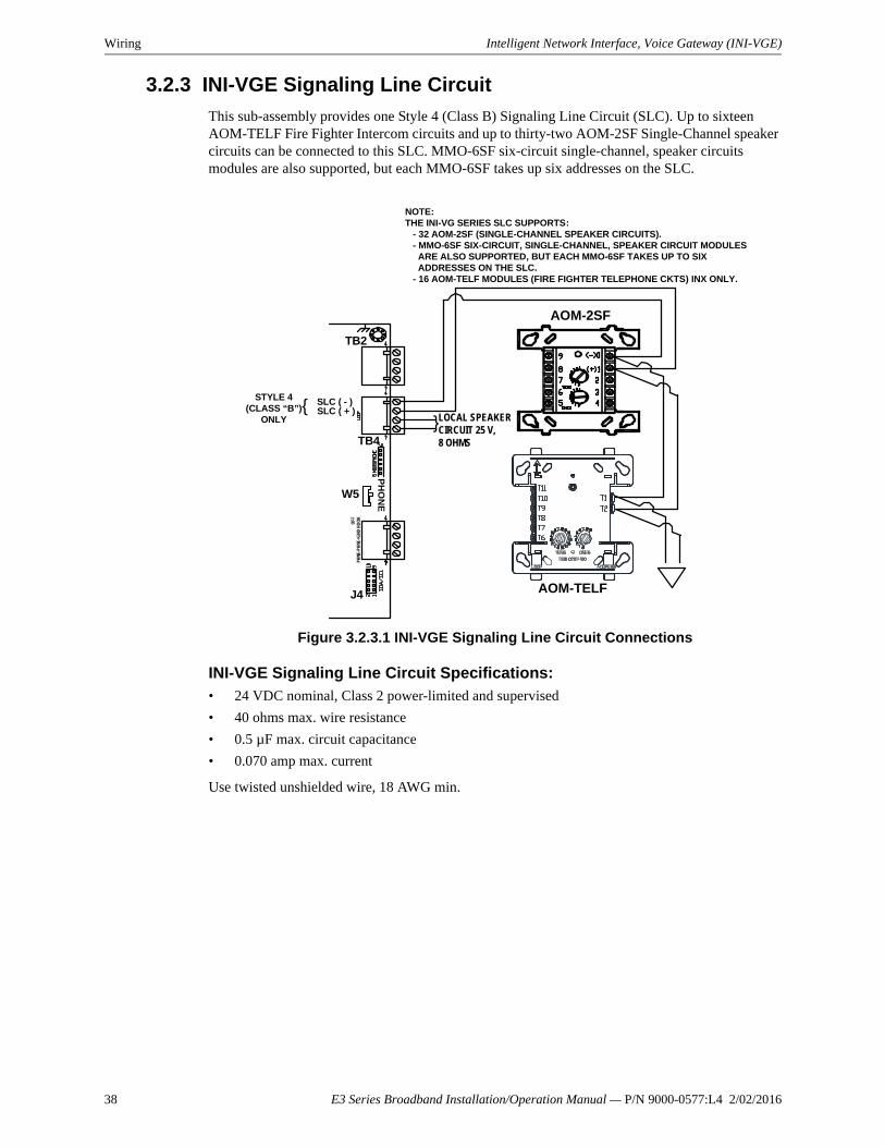
Wiring Intelligent Network Interface, Voice Gateway (INI-VGE)
3.2.3 INI-VGE Signaling Line Circuit
This sub-assembly provides one Style 4 (Class B) Signaling Line Circuit (SLC). Up to sixteen AOM-TELF Fire Fighter Intercom circuits and up to thirty-two AOM-2SF Single-Channel speaker circuits can be connected to this SLC. MMO-6SF six-circuit single-channel, speaker circuits modules are also supported, but each MMO-6SF takes up six addresses on the SLC.
Figure 3.2.3.1 INI-VGE Signaling Line Circuit Connections
INI-VGE Signaling Line Circuit Specifications:• 24 VDC nominal, Class 2 power-limited and supervised
• 40 ohms max. wire resistance
• 0.5 µF max. circuit capacitance
• 0.070 amp max. current
Use twisted unshielded wire, 18 AWG min.
}
}
SLC ( + )SLC ( - )
AOM-2SF
AOM-TELF
TB2
TB4
J4
OFF
PHN
E-PH
NE+
GN
D H
OO
K
LOCAL SPEAKER CIRCUIT 25 V, 8 OHMS
NOTE:THE INI-VG SERIES SLC SUPPORTS: - 32 AOM-2SF (SINGLE-CHANNEL SPEAKER CIRCUITS). - MMO-6SF SIX-CIRCUIT, SINGLE-CHANNEL, SPEAKER CIRCUIT MODULES ARE ALSO SUPPORTED, BUT EACH MMO-6SF TAKES UP TO SIX ADDRESSES ON THE SLC. - 16 AOM-TELF MODULES (FIRE FIGHTER TELEPHONE CKTS) INX ONLY.
STYLE 4(CLASS “B”)
ONLY
W5P
HO
NE
38 E3 Series Broadband Installation/Operation Manual — P/N 9000-0577:L4 2/02/2016
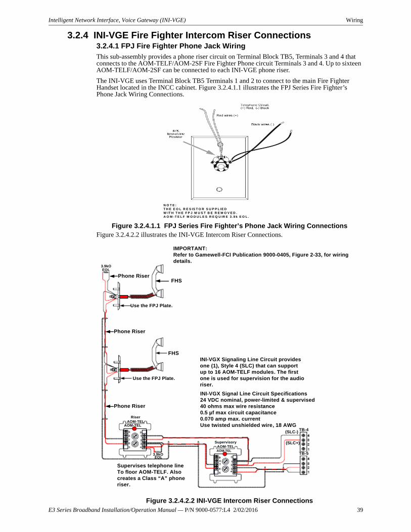
Intelligent Network Interface, Voice Gateway (INI-VGE) Wiring
3.2.4 INI-VGE Fire Fighter Intercom Riser Connections3.2.4.1 FPJ Fire Fighter Phone Jack Wiring
This sub-assembly provides a phone riser circuit on Terminal Block TB5, Terminals 3 and 4 that connects to the AOM-TELF/AOM-2SF Fire Fighter Phone circuit Terminals 3 and 4. Up to sixteen AOM-TELF/AOM-2SF can be connected to each INI-VGE phone riser.
The INI-VGE uses Terminal Block TB5 Terminals 1 and 2 to connect to the main Fire Fighter Handset located in the INCC cabinet. Figure 3.2.4.1.1 illustrates the FPJ Series Fire Fighter’s Phone Jack Wiring Connections.
Figure 3.2.4.1.1 FPJ Series Fire Fighter’s Phone Jack Wiring ConnectionsFigure 3.2.4.2.2 illustrates the INI-VGE Intercom Riser Connections.
Figure 3.2.4.2.2 INI-VGE Intercom Riser Connections
N O T E :T H E E O L R E S IS T O R S U P P L IE D W IT H T H E F P J M U S T B E R E M O V E D . A O M -T E L F M O D U L E S R E Q U IR E 3 .9 k E O L .
IMPORTANT:Refer to Gamewell-FCI Publication 9000-0405, Figure 2-33, for wiring details.
Use the FPJ Plate.
FHSPhone Riser
Phone Riser
FHS
Use the FPJ Plate.
Phone Riser
Supervises telephone lineTo floor AOM-TELF. Alsocreates a Class “A” phoneriser.
INI-VGX Signaling Line Circuit providesone (1), Style 4 (SLC) that can support up to 16 AOM-TELF modules. The first one is used for supervision for the audioriser.
INI-VGX Signal Line Circuit Specifications24 VDC nominal, power-limited & supervised40 ohms max wire resistance0.5 µf max circuit capacitance0.070 amp max. currentUse twisted unshielded wire, 18 AWG
TB-4(SLC-)
(SLC+)
TB-5EOL
3.9kO
EOL3.9kO
AOM-TEL
RiserAOM-TEL
AOM-TEL
SupervisoryAOM-TEL
E3 Series Broadband Installation/Operation Manual — P/N 9000-0577:L4 2/02/2016 39

Wiring Intelligent Network Interface, Voice Gateway (INI-VGE)
3.2.5 INI-VGE Connections to Remote ASM-16 Sub-Assemblies
An INI-VGE installed in an INCC-C Command Center assembly can support up to sixteen ASM-16 programmable switch sub-assemblies. The INCC-C cabinet has space for up to six ASM-16 sub-assemblies (there are three spaces available, if a microphone and fire fighter handset are included). INI-VGE TB6 provides a hardwire connection between the INI-VGE and any ASM-16 mounted in a different cabinet.
If the ASM-16 sub-assemblies are mounted in the same cabinet as the INI-VGE, connect the ASM-16 sub-assemblies directly by a ribbon cable (see Table 2.7.4.1).
Figure 3.2.5.1 INI-VGE Connections to the Remote ASM-16 Sub-Assemblies
3.2.6 INI-VGE Earth Ground Connection
Connect INI-VGE TB3 to earth ground for full protection against transient voltages, power surges and to conform to the National Electrical Code, NFPA 70, Article 760.
NOTE: For wiring details, see the ASM-16 and ANU-48 Wiring Connections (Table 2.7.4.1 and Figure 2.7.4.1).
Designation Description Comments
TB6-1 (+ 24 VDC) 1st Remote ASM-16 TB1-3
TB6-2 (RS-485 COM B) 1st Remote ASM-16 TB1-2
TB6-3 (RS-485 COM A) 1st Remote ASM-16 TB1-1
TB6-4 (Common) 1st Remote ASM-16 TB1-4
Table 3.2.5.1 INI-VGE to Remote ASM-16s
NOTE:USE EITHER THE RS-485 LOCALOR RS-485 REMOTE CONNECTIONDO NOT USE BOTH.
TO 1ST REMOTE ASM-16/ANU-48 TB1-4 (COMMON)TO 1ST REMOTE ASM-16/ANU-48 TB1-1 (RS-485 COM A)TO 1ST REMOTE ASM-16/ANU-48 TB1-2 (RS-485 COM B)TO 1ST REMOTE ASM-16/ANU-48 TB1-3 (+24 VDC)CONNECT TO 1ST REMOTE ASM-16/ANU-48 TERMINAL BLOCK TB1IN EACH REMOTE CABINET (INCC ONLY).
TB6TB2
RS-485 REMOTE
TB4
41
41
LO
OP
4 3 2 1
!WARNING: EARTH GROUND REQUIREMENT:USE A COLD WATER PIPE OR A GROUND-DRIVEN ROD TO ENSURE PROPER BONDING. PANEL NEUTRAL OR CONDUIT GROUND ARE NOT ACCEPTABLE. USE 14 AWG MIN. WIRE.
40 E3 Series Broadband Installation/Operation Manual — P/N 9000-0577:L4 2/02/2016

Intelligent Network Interface, Voice Gateway (INI-VGE) Wiring
3.2.7 INI-VGE Programming Address Switch Settings
Use INI-VGE DIP Switch SW-1 to set the address that the sub-assembly will occupy on the E3 Series Classic network. Do not duplicate addresses with other sub-assemblies on the network.
For the fastest communication between nodes, set the addresses in consecutive order.
Figure 3.2.7.1 INI-VGE Address Switch Settings
on
on
on
on
on
on
on
on
on
on
on
on
on
on
on
on
=16
=8
on
on
=6
=7
on
on
=5
on
on
=14
=15
on
on
=13
on
on
AD
DR
ES
S S
WIT
CH
SE
TT
ING
S
on
=4
=3
on
=2
=1
on
on
on
=12
=11
on
=10
=9
=40
=32
=24
on
on
=30=22
=23
=3
1
on
on
=21
=29
on
on
=3
8
=39
on
on
=3
7
on
on
=56
=48
on
on
=46
=47
on
on
=45
on
on
=54
=55
on
on
=5
3
on
on
on
=20
=19
on
=28
=27
=18
=17
on
=26
=25
on
on
=36
=35
on
=34
=33
on
=43
=44
on
=41
=42
on
on
on
=52
=51
on
=50
=49
=64
=62
=63
=61
=6
0
=59
=5
8
=5
7
SW
ITC
H D
OW
N (
ON
)S
WIT
CH
UP
(O
FF
)
78
35
64
21
78
35
64
21
78
35
64
21
78
35
64
21
78
35
64
21
78
35
64
21
78
35
64
21
78
35
64
21
78
35
64
21
78
35
64
21
78
35
64
21
78
35
64
21
78
35
64
21
78
35
64
21
78
35
64
21
78
35
64
21
78
35
64
21
78
35
64
21
78
35
64
21
78
35
64
21
78
35
64
21
78
35
64
21
78
35
64
21
78
35
64
21
78
35
64
21
78
35
64
21
78
35
64
21
78
35
64
21
78
35
64
21
78
35
64
21
78
35
64
21
78
35
64
21
78
35
64
21
78
35
64
21
78
35
64
21
78
35
64
21
78
35
64
21
78
35
64
21
78
35
64
21
78
35
64
21
78
35
64
21
78
35
64
21
78
35
64
21
78
35
64
21
78
35
64
21
78
35
64
21
78
35
64
21
78
35
64
21
78
35
64
21
78
35
64
21
78
35
64
21
78
35
64
21
78
35
64
21
78
35
64
21
78
35
64
21
78
35
64
21
78
35
64
21
78
35
64
21
78
35
64
21
78
35
64
21
78
35
64
21
78
35
64
21
78
35
64
21
78
35
64
21
E3 Series Broadband Installation/Operation Manual — P/N 9000-0577:L4 2/02/2016 41
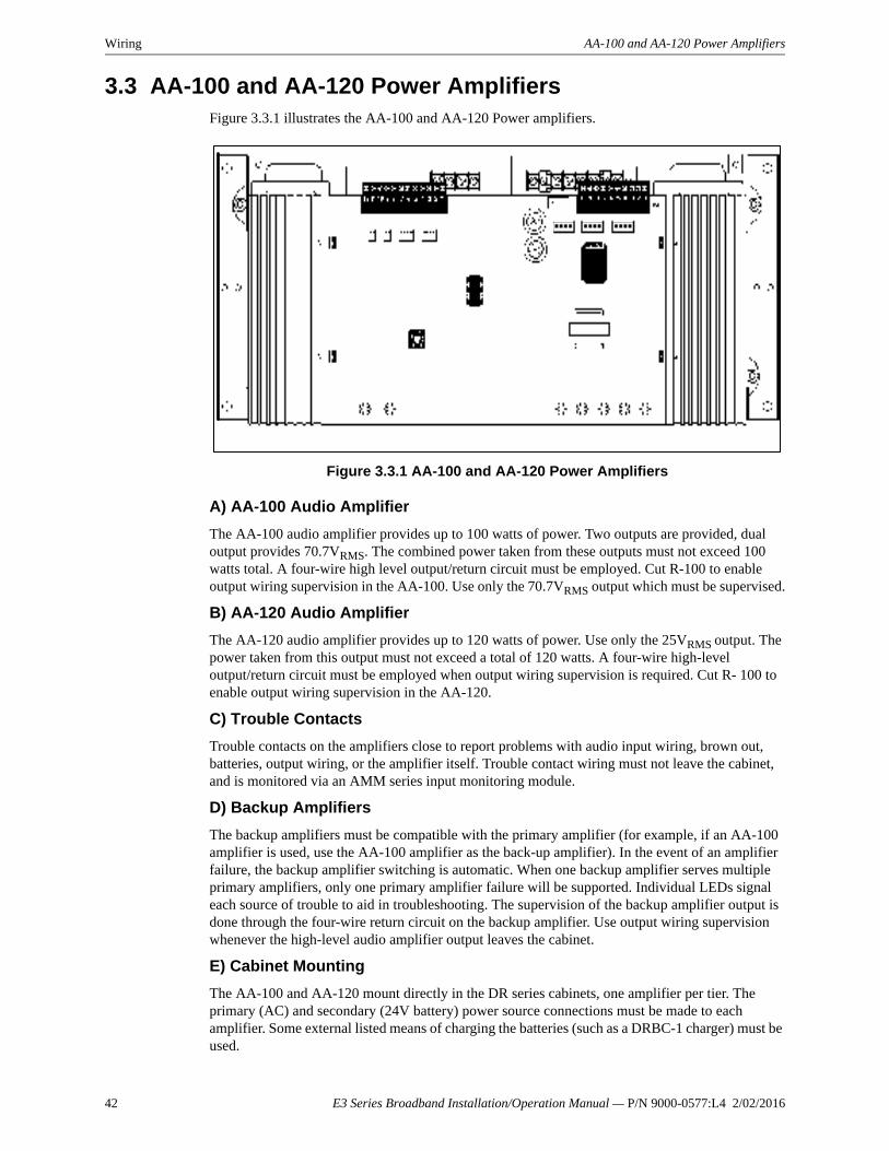
Wiring AA-100 and AA-120 Power Amplifiers
3.3 AA-100 and AA-120 Power AmplifiersFigure 3.3.1 illustrates the AA-100 and AA-120 Power amplifiers.
Figure 3.3.1 AA-100 and AA-120 Power Amplifiers
A) AA-100 Audio Amplifier
The AA-100 audio amplifier provides up to 100 watts of power. Two outputs are provided, dual output provides 70.7VRMS. The combined power taken from these outputs must not exceed 100 watts total. A four-wire high level output/return circuit must be employed. Cut R-100 to enable output wiring supervision in the AA-100. Use only the 70.7VRMS output which must be supervised.
B) AA-120 Audio Amplifier
The AA-120 audio amplifier provides up to 120 watts of power. Use only the 25VRMS output. The power taken from this output must not exceed a total of 120 watts. A four-wire high-level output/return circuit must be employed when output wiring supervision is required. Cut R- 100 to enable output wiring supervision in the AA-120.
C) Trouble Contacts
Trouble contacts on the amplifiers close to report problems with audio input wiring, brown out, batteries, output wiring, or the amplifier itself. Trouble contact wiring must not leave the cabinet, and is monitored via an AMM series input monitoring module.
D) Backup Amplifiers
The backup amplifiers must be compatible with the primary amplifier (for example, if an AA-100 amplifier is used, use the AA-100 amplifier as the back-up amplifier). In the event of an amplifier failure, the backup amplifier switching is automatic. When one backup amplifier serves multiple primary amplifiers, only one primary amplifier failure will be supported. Individual LEDs signal each source of trouble to aid in troubleshooting. The supervision of the backup amplifier output is done through the four-wire return circuit on the backup amplifier. Use output wiring supervision whenever the high-level audio amplifier output leaves the cabinet.
E) Cabinet Mounting
The AA-100 and AA-120 mount directly in the DR series cabinets, one amplifier per tier. The primary (AC) and secondary (24V battery) power source connections must be made to each amplifier. Some external listed means of charging the batteries (such as a DRBC-1 charger) must be used.
42 E3 Series Broadband Installation/Operation Manual — P/N 9000-0577:L4 2/02/2016

AA-100 and AA-120 Power Amplifiers Wiring
3.3.1 Primary/Secondary Power Requirements for the AA-100/AA-120 Audio Amplifiers
Primary power required for the AA-100, and AA-120 amplifiers are 120VAC. Secondary power (24 VDC battery) connections must be made at the designated terminals shown in Figure 3.3.2.1. Secondary power may be obtained from any source of 24 VDC that is Listed for fire alarm signaling and it has sufficient alarm and standby capacity (etc.). Use Table 3.3.1.1 to calculate the amplifier secondary (battery) power requirements.
Qty Sub-assembly Description Supv.
Current Alarm
Current
Total Supv.
Current
Total Alarm
Current
AA-100 AA-100 Primary amplifier 0.050 A 7.3 A
AA-120 AA-120 Primary amplifier 0.050 A 7.3 A
AA-120 AA-120 Back up amplifier 0.050 A 0.30 A
Additional current consuming devicespowered from the power supply
TOTALS:
User Calculation Totals (See Notes 1 & 2)
A Total supervisory current.
B Enter number of standby hours required. 24
C Multiply Line A by hours in Line B.
D Total alarm current.
E Enter alarm sounding period in hours* (0.25 hr).
F Multiply Line D by Line E.
G Add Line C & Line F.
H Multiply Line G by 1.2 to arrive at total ampere/hours required.
NOTES
NOTE 1: For Emergency Voice/Alarm Communication service, the system shall be capable of operating for 24 hours under a maximum normal load and then operating during an alarm condition for a period of 2 hours. Fifteen (15) minutes of evacuation alarm operation at maximum alarm load shall be considered the equivalent of 2 hours of alarm operation.
NOTE 2: Maximum alarm current from 55AH batteries must not exceed 20A.Use the next size battery with capacity greater than required. Maximum alarm current from 31 AH batteries must not exceed 9A.The system batteries must be replaced as a set.
Table 3.3.1.1 AA-100/AA-120 Amplifier Standby Battery - Calculation Chart
E3 Series Broadband Installation/Operation Manual — P/N 9000-0577:L4 2/02/2016 43
Wiring AA-100 and AA-120 Power Amplifiers
3.3.1.1 ACT-1 Audio Coupling Transformer
Overview
The ACT-1 Audio Coupling Transformer couples a low-level audio to the audio amplifiers. The unit can be used to couple a low-level audio signal up to eight devices. Multiple ACT-1s are required for amplifiers on multiple channels. It provides electrical isolation for equipment powered by separate power supplies with ground fault detection enabled. In addition, the ACT-1 provides common mode noise rejection (CMNR), greatly reducing crosstalk from the SLCs.
Applications
You can install the transformer in any application that uses AA-100, or AA-120 audio amplifiers, subject to the following restrictions.
• The amplifiers must mount remotely from the source of the low-level audio devices, such as the INI-VGE.
• The power supplies in the main control panel cabinet and the remote cabinets do not share the same common.
• Ground fault is enabled on each power supply.
In larger systems, capacitance becomes a critical factor in creating sporadic and difficult-to-find ground faults along a single common connection. In these systems—as in systems that expand—use an ACT-1 if possible.
Isolating Power Supplies
Isolated power supplies, each with respective ground fault detection circuits enabled, are often used to aid the quick location of ground faults in the large systems. This task is more difficult if the entire system (main and all remote devices) share the same common connection and the power supply in the main control panel cabinet provides ground fault detection.
For example, use a system consisting of a remote annunciator powered from a local supply within the same cabinet, but connected through an RS-485 circuit to the main control panel. A common connection occurs (although a poor one) along the RS-485 interface. Therefore, the power supplies in this system are not adequately isolated and problems will occur (such as intermittent reports of a ground fault when each power supply’s ground fault detection signal interacts with the signal from the other power supply). In this case, the earth fault detection of the remote power supply must be disabled and a good common connection must be made between the two systems. Although an ACT-1 is not required for amplifiers mounted in this remote cabinet, the installation of an ACT-1 can reduce CMN from the SLC.
44 E3 Series Broadband Installation/Operation Manual — P/N 9000-0577:L4 2/02/2016

AA-100 and AA-120 Power Amplifiers Wiring
3.3.1.2 ACT-1 Audio Coupling Transformer InstallationTo connect an ACT-1 to an AA-100 or an AA-120 amplifier, follow these steps and refer to Figure 3.3.1.2.1:
1. Connect the ACT-1 to the first amplifier in the chain by inserting P1 pins of the ACT-1 into Terminal Block P3 of the amplifier as shown in Figure 3.3.1.2.1. Tighten the screws securely.
2. Using the supplied cable, connect the EARTH terminal on each ACT-1 to P8 on the AA-100/ AA-120.
3. Connect the low-level AUDIO IN circuit to the Terminal Block TB1 on the ACT-1.
Figure 3.3.1.2.1 ACT-1 Connections
NOTE: To obtain the highest sound quality, observe polarity of audio signal when connecting the speakers.
LowLevel
AMG POLARITY
RETURN
OUT
P4
P5
AMG
P3 on AA-30P4 on AA-100/AA-120
Shield Out (through)
OUTOUT
IN
Earth Common
Terminal designation on the ACT-1
ShieldTHRU +THRU -
ShieldAUDIO IN +AUDIO IN -
COM EARTH S THRU AUDIO IN
E3 Series Broadband Installation/Operation Manual — P/N 9000-0577:L4 2/02/2016 45
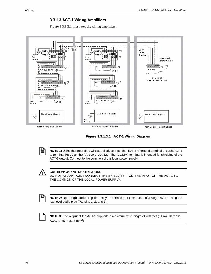
Wiring AA-100 and AA-120 Power Amplifiers
3.3.1.3 ACT-1 Wiring Amplifiers
Figure 3.3.1.3.1 illustrates the wiring amplifiers.
Figure 3.3.1.3.1 ACT-1 Wiring Diagram
See Note 2
AA-30
P3
See Note 3
AA-100 or AA-120
AA-100 or AA-120
P3
P3
TB1
P1
R-470ELR
Main Power Supply
Rem ote Am plifier Cabinet
Main Power Supply
Rem ote Am plifier Cabinet
Main Power Supply
Main Control Panel Cabinet
Origin of Main Audio Riser
Low-LevelAudio
Low -LevelAudio Return
AMG-1P4
See Note 2
AA-30
AA-30
AA-100 or AA-120P3
P3
P3
P1
TB1
See Note 1
See Note 3
NOTE 1: Using the grounding wire supplied, connect the “EARTH” ground terminal of each ACT-1 to terminal P8-10 on the AA-100 or AA-120. The “COMM” terminal is intended for shielding of the ACT-1 output. Connect to the common of the local power supply.
! CAUTION: WIRING RESTRICTIONSDO NOT AT ANY POINT CONNECT THE SHIELD(S) FROM THE INPUT OF THE ACT-1 TO THE COMMON OF THE LOCAL POWER SUPPLY.
NOTE 2: Up to eight audio amplifiers may be connected to the output of a single ACT-1 using the low-level audio plug (P1, pins 1, 2, and 3).
NOTE 3: The output of the ACT-1 supports a maximum wire length of 200 feet (61 m). 18 to 12
AWG (0.75 to 3.25 mm2).
46 E3 Series Broadband Installation/Operation Manual — P/N 9000-0577:L4 2/02/2016
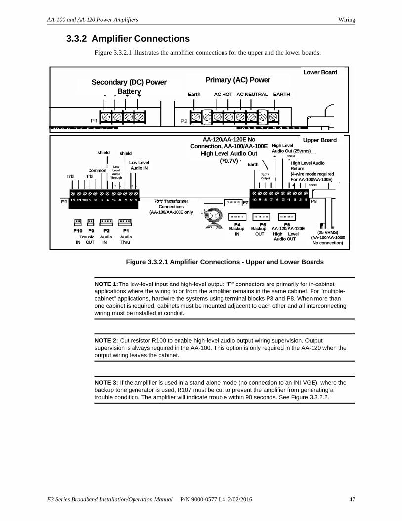
AA-100 and AA-120 Power Amplifiers Wiring
3.3.2 Amplifier Connections
Figure 3.3.2.1 illustrates the amplifier connections for the upper and the lower boards.
Figure 3.3.2.1 Amplifier Connections - Upper and Lower Boards
NOTE 1:The low-level input and high-level output "P" connectors are primarily for in-cabinet applications where the wiring to or from the amplifier remains in the same cabinet. For "multiple-cabinet" applications, hardwire the systems using terminal blocks P3 and P8. When more than one cabinet is required, cabinets must be mounted adjacent to each other and all interconnecting wiring must be installed in conduit.
NOTE 2: Cut resistor R100 to enable high-level audio output wiring supervision. Output supervision is always required in the AA-100. This option is only required in the AA-120 when the output wiring leaves the cabinet.
NOTE 3: If the amplifier is used in a stand-alone mode (no connection to an INI-VGE), where the backup tone generator is used, R107 must be cut to prevent the amplifier from generating a trouble condition. The amplifier will indicate trouble within 90 seconds. See Figure 3.3.2.2.
Secondary (DC) PowerBattery
Primary (AC) Power
Earth AC HOT AC NEUTRAL EARTH
Lower Board
Upper Board
Trbl TrblCommon
shield shield
LowLevel Audio
Through
Low Level Audio IN
70 V TransformerConnections
(AA-100/AA-100E only
AA-120/AA-120E NoConnection, AA-100/AA-100E
High Level Audio Out(70.7V)
High LevelAudio Out (25vrms)
High Level AudioReturn(4-wire mode requiredFor AA-100/AA-100E)
Earth
70.7 VOutput
shield
shield
Trouble Audio AudioIN OUT IN Thru
Backup Backup AA-120/AA-120E IN OUT High Level Audio OUT
(25 VRMS)(AA-100/AA-100ENo connection)
E3 Series Broadband Installation/Operation Manual — P/N 9000-0577:L4 2/02/2016 47

Wiring AA-100 and AA-120 Power Amplifiers
3.3.2 Amplifier Connections (Continued)Figure 3.3.2.2 illustrates the stand alone operation.
Figure 3.3.2.2 “Stand Alone” Operation
3.3.3 Adjusting Audio Gain Level
A multi-position rotary switch allows the installer to adjust the gain of the audio output signal to compensate for audio line losses. After correct adjustment, the audio amplifier will produce its maximum rated output power.
To adjust:
After the complete installation of all amplifiers and associated circuitry, with the low level audio input to the amplifier set for normal standby, use a small slotted screwdriver to position the rotary switch until the NORMAL LEVEL LED is lit and the INCORRECT LEVEL LED is off. At this point, the audio gain is properly adjusted.
Cut R107 to enable“Stand Alone” operation
Cut R100 to enable4-wire outputsupervision
NOTE: Ensure that a 470-ohm impedance matching resistor has been installed on the last amplifier (P3 Terminals 1 and 2). Failure to do so will result in calibration difficulty.
48 E3 Series Broadband Installation/Operation Manual — P/N 9000-0577:L4 2/02/2016

AA-100 and AA-120 Power Amplifiers Wiring
3.3.3. Adjusting Audio Gain Level (Continued)Figure 3.3.3.1 illustrates the audio gain switch.
Figure 3.3.3.1 Audio Gain Switch
3.3.4 LEDs
Figure 3.3.4.1 includes a description of the LEDs.
Figure 3.3.4.1 LEDs
Audio Gain
Normal Level LED – During normal (non-alarm) conditions, when this green LEDis on and the Incorrect Level LED is off,the audio amplifier is adjusted properly.
Note: During a loss of primary (AC)power, when the amplifier is operating onsecondary (battery) power, no LEDs willlight on the amplifier.
Incorrect Level LED – During normal(non-alarm) conditions, this LED indi-cates that the audio amplifier is out ofadjustment. When this LED is on and theNormal Level LED is off, the audio leveladjustment is too low. When both thisLED and the Normal Level LED are on,the audio level adjustments is too high.
Battery Trouble LED – The batteryvoltage has fallen below a sufficientlevel.
Brownout LED – AC power sourcehas fallen below an acceptable level.
Output Trouble LED – An open/shortcircuit condition exists in the 4-wirehigh-level output (or 70 V transformeron the AA-100/AA-100E).
Input Trouble LED – Loss of the low-level audio input signal, or internalamplifier failure.
Amplifier Trouble LED – Loss of thehigh-level audio signal, or internal amplifier failure.
Note: The amplifier will indicate a trouble condition within 90 seconds.
SW1 (see detail below)
E3 Series Broadband Installation/Operation Manual — P/N 9000-0577:L4 2/02/2016 49

Wiring AA-100 and AA-120 Power Amplifiers
3.3.5 Selecting the Default Backup Tone
Use SW1, located in the lower right corner of the amplifier circuit board, to select Hi/Lo or Slow Whoop as the default backup tone. The backup tone will start automatically if the low-level audio input to the amplifier is lost or when the amplifier has been configured for stand-alone operation. Figure 3.3.5.1 illustrates the SW1 backup tone stand-alone tone switch.
Figure 3.3.5.1 SW1 Backup Tone Stand-Alone Tone Switch
HI/LO
SLOWWHOOP
SW1Backup Tone/Stand-AloneTone Switch
50 E3 Series Broadband Installation/Operation Manual — P/N 9000-0577:L4 2/02/2016

AA-100 and AA-120 Power Amplifiers Wiring
3.3.6 Backup Amplifier
An AA-120 amplifier can be used to backup one or more amplifiers. In the event of an amplifier failure, the backup amplifier switching is automatic. Figure 3.3.6.1 illustrates the backup amplifier switching.
Figure 3.3.6.1 Backup Amplifier
P8, 7 (-)P8, 8 (+)
AA-100 Output100 Watts maximum
70.7 VRMS
Maximum output 100 watts from both of these outputs
(combined total)
AA-100 Output100 Watts maximum
25 VRMS
P8, 5 (-)P8, 6 (+)
AA-100/AA-100E Primary Amplifier
Cut R100
AA-120 Output120 Watts maximum 25 VRMS
P8, 5 (-)P8, 6 (+)
AA-120/AA-120E Primary Amplifier
P8, 2 (-)P8, 3 (+)
Backup Amplifier AA-100/AA or AA-120 Cut R100
Supervision for backup configuration
Optional4-Wire Return
Shield
E3 Series Broadband Installation/Operation Manual — P/N 9000-0577:L4 2/02/2016 51

Wiring Speaker Circuit Connections
3.4 Speaker Circuit Connections
3.4.1 Speaker Switching
The amplified signal from each audio amplifier must be connected to a control module, which will switch the signal to a speaker circuit when necessary. Figure 3.4.1.1 through Figure 3.4.1.4 illustrate the wiring configurations for the AA-100, and AA-120 audio amplifiers.
Figure 3.4.1.1 Speaker Switching Configuration for the AA-100 (Class B) with AOM-2SF (Style Y)
Figure 3.4.1.2 Speaker Switching Configuration for the AA-100 (Class B) with AOM-2SF (Style Z)
only)
Control ModuleAOM-2SF
-+
+ -
Cut resistor R100 to enable high level audiooutput wiring supervisionin four-wire mode
High LevelAudio Return
(4-wire mode requiredfor AA-100)
47 K EOLResistorA2143-00Module polarities
Are shown in alarm
+
-
-
-+
Speaker Switching Circuit – NFPA Style YSpeakers must be Listed for fire protection
Maximum Load 43.75 watts max.Up to 70.7 VRMS
(.35 power factor)
HighLevel Audio Out (70.7V)
SupervisedPower-limited
AA-100 Upper Board
<
Speaker Switching Circuit NFPA Style ZSpeakers must be Listed for fire protectionMaximum Load 43. 75 watts max. up to 70.7 VRMS
(.35 power factor)
EOLResistorIs internalAt terminals8 and 9Module polarities
are shown in alarm
Cut resistor R100 to enable high level audioOutput wiring supervisionin four-wire mode
High LevelAudio Return(4-wire mode requiredfor AA-100)
Bypass CapacitorsA2143-20
100 µf 10VNon-polarized<10 µA leakage
AA-100 Upper Board
AA-100 A High LevelAudio Out 70.7 VSupervisedPower-limited
Control ModuleAOM-2SF
R100
+-
-+
+ --+
52 E3 Series Broadband Installation/Operation Manual — P/N 9000-0577:L4 2/02/2016

Speaker Circuit Connections Wiring
3.4.1 Speaker Switching (Continued)
Figure 3.4.1.3 Speaker Switching Configuration for the AA-120 (Class B) with AOM-2SF (Style Y)
Figure 3.4.1.4 Speaker Switching Configuration for the AA-120 (Class B) with AOM-2SF (Style Z)
Communication Line28 VDC max.twisted-pair is recommended
From panel orPrevious device
+-
+- To Next
Device
All wiring is supervised.
Speaker Switching Circuit-NFPA Style YSpeakers must be Listed for fire protection
Maximum Load 43.75 watts max.(.35 power factor)
Control ModuleAOM-2SF
AA-120 in same cabinet as AOM-2SF
Module polaritiesAre shown in alarm
-+
47 K EOLResistorA2143-00
AA-120 Upper Board
High LevelAudio Out(25 VRMS)
Not SupervisedPower-limited
+ -
SLC
High LevelAudio Out(25 VRMS)
SupervisedPower-limited
AA-120 Upper Board
Speaker Switching Circuit-NFPA Style ZSpeakers must be Listed for fire protectionMaximum Load 43.75 watts max. (.35 power factor)
Cut resistor R100 to enable high-level audiooutput wiring supervisionIn four-wire mode
Bypass CapacitorsA21430-20
High Level Audio Return(4-wire mode requiredfor AA-100)
100 µf, 10VNon-polarized<10 µA leakage
EOLResistoris internalat terminals8 and 9
Control ModuleAOM-2SF
Module polaritiesAre shown in alarm
-+
+-
-+
E3 Series Broadband Installation/Operation Manual — P/N 9000-0577:L4 2/02/2016 53

Wiring Speaker Circuit Connections
3.4.2 Speaker Wire
Use twisted, SHIELDED pair, 18 AWG. minimum. Make sure the shield is run continuously through the speaker circuits with no segments of the shield left floating. Do not tie the shield to conduit or junction boxes in the field. Terminate the drain wire back at the panel's location to system negative. Style Z circuits do not require an end-of-line resistor. This is included on the AA amplifier.
Table 3.4.2.1 can be used as a guide to determine the wire requirements for each speaker circuit.
NOTE: Strobe notification appliances should be connected to the notification appliance circuits of the associated 7100 control or SNAC supplementary panel.
Circuit Length in Feet (Meters)
Watts 10 ft. 25 ft. 50 ft. 100 ft. 250 ft. 500 ft. 1000 ft.
(3 m) (7.6 m) (15.25 m) (30.5 m) (76 m) (152.5 m) (305 m)
100 18 18 18 16 14 10 N/A AWG
120 18 18 18 18 16 14 10 AWG
N/A = Not Allowed
NOTE: Use, twisted, SHIELDED wire.
Table 3.4.2.1 AA Series Amplifiers Speaker Circuit Wiring Requirements
54 E3 Series Broadband Installation/Operation Manual — P/N 9000-0577:L4 2/02/2016

Dual-Channel Classic Wiring
3.5 Dual-Channel ClassicThe Dual-Channel Classic is a dual-channel configuration used in the bulk audio voice evacuation systems, such as the NetSOLO® and E3 Series® Classic Systems. This alternate design uses one AOM-2RF module and one AOM-2SF module. The AOM-2RF module provides the dual-channel for audio, and the AOM-2SF module provides the broadcast channel for zone paging/alarm tone. Figure 3.5.1 illustrates the dual-channel bulk audio configuration.
Figure 3.5.1 Dual-Channel Bulk Audio Configuration
NOTE: For additional installation information, refer to the AOM-2SF Installation Instructions, P/N: I56-3550-001 and the AOM-2RF Installation Instructions, P/N: I56-3551-002.
47K EOL
SLC(-) T1
SLC(+) T2
NA
N.O. T5
AOM-2RF
T10 COMM 2
T9 N.C. 2
T8 N.O. 2
T7 COMM 1
T6 N.C. 1
SLC(-) T1SLC(+) T2
AOM-2SF
T10 EXT SUP+
T9 A-
T8 A+
T7 A/B+
T6 A/B-
T11 EXT SUP-
SLC
AA-100/120 AMP ALARM CHANNEL
AA-100/120 AMP PAGE CHANNEL
AUDIO CIRCUITS WIRING MUST BE TWISTED-PAIR SHIELD
DUAL-CHANNEL BULK AUDIO
TENS ONES
TENS ONES
E3 Series Broadband Installation/Operation Manual — P/N 9000-0577:L4 2/02/2016 55

56 E3 Series Broadband Installation/Operation Manual — P/N 9000-0577:L4 2/02/2016
Section 4: Transient Over-Voltage Protection
4.1 Routing Of Class 2 Power-Limited Field Wiring CircuitsUL Standard 864, (Control Units for Fire Protective Signaling Systems), requires that a minimum of ¼ inch separation be maintained between Class 2 power-limited circuits and non power-limited circuits. The control unit is designed so the required separation between these circuits (Class 2 power-limited vs. non power-limited) is maintained at the field wiring terminals.
In order to fully comply with the intent of these requirements, however, the minimum ¼ inch separation must also be maintained between the field wiring conductors of Class 2 power-limited circuits and non power-limited circuits. This may be accomplished by routing the field wiring as shown in Figure 4.1.1.
Unless otherwise indicated on the unit, all field wiring circuits are Class 2 power-limited except:
• AC power circuit
• Standby battery circuit
• Power supply output
• Municipal box (auxiliary) circuit
Figure 4.1.1 Class 2 Power-Limited
NOTE: Route all field wiring to maintain a minimum of 1/4 inch separation between Class 2 power-limited and non power-limited circuit types. Additional conduit connections may be made in the respective Class 2 power-limited and non power-limited areas of the enclosure if needed to maintain this required minimum separation.
INI-VGE E3 SERIES©
CONNECTIONS(CLASS 2 POWER-LIMITED)
INI-VGE
CLASS 2 POWER-LIMITED WIRING VIA THIS CONDUITINI-VGE SIGNALING LINE CIRCUIT(CLASS 2 POWER-LIMITED)120 VAC CONNECTION To AMPLIFIERS(NON POWER-LIMITED)FIRE FIGHTER INTERCOM WIRING(CLASS 2 POWER-LIMITED)
NON-POWER-LIMITED WIRINGVIA THIS CONDUIT
CLASS 2 POWER-LIMITED WIRING VIA THIS CONDUIT
BATTERY CONNECTION
(NON POWER-LIMITED)24 VDC POWER to AMPLIFIERS
(NON POWER-LIMITED)
CLASS 2 POWER-LIMITED WIRING VIA THIS CONDUIT
BATTERIES
NOTE: Class 2 Power-limited and non power-limited circuit wiring must remain separated in the cabinet. All Class 2 power-limited circuit wiring must remain at least 0.25" away from any non power-limited wiring. All Class 2 power-limited and non power-limited wiring must enter and exit the cabinet through different knockouts and/or conduits.Class 2 Power-limited wire must be type FPL, FPLR or FPLP according to Article 760 of the National Electrical Code.

Index
Numerics7100 Features 11
AAA 42AA-100 9AA-120 10ACT-1 44Address Switch Settings
INI-VGE 41ANU-48 10ANX 12ASM-16 9
BBackup Amplifier Connections 51
CCAB-B3, CAB-D3 10
DDual-Channel Bulk Audio Configuration 55Dual-Channel Classic 55
EE3 Series Classic INI-VGE Power ConsumptionCalculation Chart 30
FFire Fighter’s Intercom Handset 25
IINCC-C 9INCC-E 10INCC-Ex 10INI 34INI-7100 FO 11INI-7100 UTP 11INI-VGE 9
Indicating and Diagnostic LEDs 33Intercom Riser Connections 39Jumpers & Cable Connections 32Power Connections 34Signaling Line Circuit 38
InstallationANU-48 22ASM-16 18INI-VGE 18
LLCD-7100 11LCD-E3 10LCD-SLP 10LDM-7100 11LEDs 49
NNGA 10, 26
PPM-9 10PM-9G 10Power Amplifiers
AA-100 and AA-120 42Power Consumption
ANU-48 30AOM-2SF 30AOM-TELF 30ASM-16 30INI-VGE 30Microphone 30MMO-6SF 30NGA 30Telephone 30
Power RequirementsAA-100 43AA-120 43
RRAN-7100 11Remote Annunciators
LCD-SLP 10RPT-E3-UTP 12
SS3 Series
FLPS-7 13LCD-SLP 13SLC95-PM 13SLC-PM 13SLP-E3 13
Speaker Circuit Connections 52
VVoice Paging Microphone 24
WWiring Connections
E3 Series Broadband Installation/Operation Manual — P/N 9000-0577:L4 2/02/2016 57

W–W Index
ASM-16 or ANU-48 19E3 Classic Network (INI-VGE Only) 36E3 Series Classic Network 36INI-VGE Series 31
Wiring DiagramsACT-1 45ASM-16 and ANU-48 21INI-VGE 29INI-VGE Connections 35INI-VGE Power Connections 34
58 E3 Series Broadband Installation/Operation Manual — P/N 9000-0577:L4 2/02/2016

Manufacturer Warranties and Limitation of LiabilityManufacturer Warranties. Subject to the limitations set forth herein,Manufacturer warrants that the Products manufactured by it in itsNorthford, Connecticut facility and sold by it to its authorizedDistributors shall be free, under normal use and service, from defectsin material and workmanship for a period of thirty six months (36)months from the date of manufacture (effective Jan. 1, 2009). TheProducts manufactured and sold by Manufacturer are date stamped atthe time of production. Manufacturer does not warrant Products thatare not manufactured by it in its Northford, Connecticut facility butassigns to its Distributor, to the extent possible, any warranty offeredby the manufacturer of such product. This warranty shall be void if aProduct is altered, serviced or repaired by anyone other thanManufacturer or its authorized Distributors. This warranty shall alsobe void if there is a failure to maintain the Products and the systems inwhich they operate in proper working conditions.
MANUFACTURER MAKES NO FURTHER WARRANTIES, ANDDISCLAIMS ANY AND ALL OTHER WARRANTIES, EITHEREXPRESSED OR IMPLIED, WITH RESPECT TO THE PRODUCTS,TRADEMARKS, PROGRAMS AND SERVICES RENDERED BYMANUFACTURER INCLUDING WITHOUT LIMITATION,INFRINGEMENT, TITLE, MERCHANTABILITY, OR FITNESS FORANY PARTICULAR PURPOSE. MANUFACTURER SHALL NOT BELIABLE FOR ANY PERSONAL INJURY OR DEATH WHICH MAYARISE IN THE COURSE OF, OR AS A RESULT OF, PERSONAL,COMMERCIAL OR INDUSTRIAL USES OF ITS PRODUCTS.
This document constitutes the only warranty made by Manufacturerwith respect to its products and replaces all previous warranties and isthe only warranty made by Manufacturer. No increase or alteration,written or verbal, of the obligation of this warranty is authorized.Manufacturer does not represent that its products will prevent any lossby fire or otherwise.
Warranty Claims. Manufacturer shall replace or repair, atManufacturer's discretion, each part returned by its authorizedDistributor and acknowledged by Manufacturer to be defective,provided that such part shall have been returned to Manufacturer withall charges prepaid and the authorized Distributor has completedManufacturer's Return Material Authorization form. The replacementpart shall come from Manufacturer's stock and may be new orrefurbished. THE FOREGOING IS DISTRIBUTOR'S SOLE ANDEXCLUSIVE REMEDY IN THE EVENT OF A WARRANTY CLAIM.
Warn-HL-08-2009.fm
E3 Series Broadband Installation/Operation Manual — P/N 9000-0577:L4 2/02/2016 59

Gamewell-FCI12 Clintonville Road
Northford, CT 06472-1610 USA203-484-7161
fax 203-484-7118
www.gamewell-fci.com


