38
Mitsubishi Hitachi Power Systems Clean Coal Technologies for IGCC Power Plants Sep 6, 2017 Yoshiyuki Wakabayashi Executive Vice President Mitsubishi Hitachi Power Systems, LTD

Mitsubishi Hitachi Power Systems
Clean Coal Technologies for IGCC Power Plants
Sep 6, 2017
Yoshiyuki Wakabayashi
Executive Vice President
Mitsubishi Hitachi Power Systems, LTD
© 2017 Mitsubishi Hitachi Power Systems, Ltd. All Rights Reserved.
Proprietary and Confidential Information. This document or information cannot be reproduced, transmitted, or disclosed without prior written consent of Mitsubishi Hitachi Power Systems,Ltd.
1
1. Introduction
2. Features of IGCC system
3. Development
4. Commercial Plant
5. Examples of Feasibility Study
6. Future Applications
7. Conclusion
Contents
© 2017 Mitsubishi Hitachi Power Systems, Ltd. All Rights Reserved.
Proprietary and Confidential Information. This document or information cannot be reproduced, transmitted, or disclosed without prior written consent of Mitsubishi Hitachi Power Systems,Ltd.
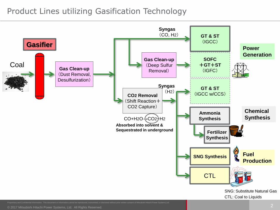
Product Lines utilizing Gasification Technology
Coal
Gasifier
GT & ST
(IGCC)
CO2 Removal
(Shift Reaction+CO2 Capture)
Power
GenerationSOFC
+GT+ST
(IGFC)Gas Clean-up
(Dust Removal,
Desulfurization)
GT & ST
(IGCC w/CCS)
Ammonia
Synthesis
Fertilizer
Synthesis
SNG Synthesis
CTL
Chemical
Synthesis
Fuel
Production
Syngas
(CO, H2)
Syngas
(H2)
CO+H2O→CO2+H2
Absorbed into solvent &
Sequestrated in underground
Gas Clean-up
(Deep Sulfur
Removal)
2
SNG: Substitute Natural Gas
CTL: Coal to Liquids

© 2017 Mitsubishi Hitachi Power Systems, Ltd. All Rights Reserved.
Proprietary and Confidential Information. This document or information cannot be reproduced, transmitted, or disclosed without prior written consent of Mitsubishi Hitachi Power Systems,Ltd.
Overview of IGCC(Integrated coal Gasification Combined Cycle)Technology
Why IGCC?
GTCC
Gasifier
GasClean-up
IGCC is the cutting-edge technology :
High Efficiency
Lower CO2 Emission & Ash Volume
Fuel Flexibility
Highly Reliable System
Its demonstration successfully finished and commercial projects have started.
3

© 2017 Mitsubishi Hitachi Power Systems, Ltd. All Rights Reserved.
Proprietary and Confidential Information. This document or information cannot be reproduced, transmitted, or disclosed without prior written consent of Mitsubishi Hitachi Power Systems,Ltd.
Why IGCC has high efficiency?
4
Gas Turbine(Brayton Cycle)
Power
Higher efficiency through coal gasification process
coupled with a combined cycle (CC) system.
① Conventional
Coal Firing System
Flue
Gas
Steam Turbine
~
Coal Firing
Boiler
Coal
Air
Steam Temp.
USC :600℃A-USC :700℃
Single Power Generation(Rankine Cycle)
② Integrated Gasification Combined Cycle (IGCC)
Double Power Generation(Combination of Brayton & Rankine Cycles)
C~ T
HRSG
~
Gas TurbineAir
Steam Turbine
Flue
Gas
Combustor
Coal
Gasifier
Clean
up
Air
Comp.
Steam Turbine(Rankine Cycle)
CondenserLoss
Power
Entropy
Temp.

© 2017 Mitsubishi Hitachi Power Systems, Ltd. All Rights Reserved.
Proprietary and Confidential Information. This document or information cannot be reproduced, transmitted, or disclosed without prior written consent of Mitsubishi Hitachi Power Systems,Ltd.
Fukushima Revitalization Power
Nakoso IGCC Power, 540 MW ( COD : 2020.9 )
Hirono IGCC Power, 540 MW ( COD : 2021.9 )
Osaki CoolGen Corp.
Osaki CoolGen Project
166 MW ( Demo. 2017 - )
IGCC Projects in Japan
Joban Joint Power Co.
Nakoso #10, 250 MW
( Demo. 2007 - , COD : 2013 )
5
IGCC Projects in Japan
© 2017 Mitsubishi Hitachi Power Systems, Ltd. All Rights Reserved.
Proprietary and Confidential Information. This document or information cannot be reproduced, transmitted, or disclosed without prior written consent of Mitsubishi Hitachi Power Systems,Ltd.
6
1. Introduction
2. Features of IGCC system
3. Development
4. Commercial Plant
5. Examples of Feasibility Study
6. Future Applications
7. Conclusion

© 2017 Mitsubishi Hitachi Power Systems, Ltd. All Rights Reserved.
Proprietary and Confidential Information. This document or information cannot be reproduced, transmitted, or disclosed without prior written consent of Mitsubishi Hitachi Power Systems,Ltd.
Air-blown IGCC System Configuration
MHPS can supply entire IGCC plants with single point responsibility
Coal Feed
Char Removal & Recycle
HeatRecovery
SteamGenerator
Gas Turbine
OxygenASU
Char
Nitrogen
Air
Off-Gas Incinerator
M
~
Combustor
Slag
Air
Air
H2SRegenerator
H2SAbsorber
NH3/Trace Element Washing
COSConverter
AirCompressor
Stack
To GypsumRecovery
Scrubber
Coal
GGH
Flare System
Highly Efficient Gasifier
Air Separation Unit (ASU)
Wet Gas Clean-up (MDEA)
Steam Turbine
Highly Efficient Gas Turbine
Gasifier / Gas Clean-up : Clean fuel gas generation from coal with high efficiency
ASU for N2 Generation:• Inerting N2 for coal transportation is produced.• O2 as a by-product is mixed with air and efficiently
utilized as gasification reaction enhancer.
Combined Cycle : Efficient Power Generation by fuel syngas
Coal is converted to syngas fuel of gas turbine.
Contaminant in syngas is cleaned up.
GTCC is fueled with syngas.
7

© 2017 Mitsubishi Hitachi Power Systems, Ltd. All Rights Reserved.
Proprietary and Confidential Information. This document or information cannot be reproduced, transmitted, or disclosed without prior written consent of Mitsubishi Hitachi Power Systems,Ltd.
Features of IGCC system (How the gasifier works)
Combustor (1st Stage)
Function:• Combustion of coal and char
(Exothermic reaction)C+O2→CO2
• Stable discharge of molten slag down into the water bath
Reductor (2nd Stage)
Function:• Gasification utilizing sensible heat
of high temp. gas from Combustor(Endo-thermic reaction)C+CO2→2CO / C+H2O→CO+H2
Waterwall
Coal(Upper)
Char
Syngas
Coal(Lower)
Oxidizer
Slag
① 2-Chamber/2-StageConfiguration
② No quench steam / gasis injected for cooling syngas because of the endothermic reaction in the Reductor. Waterwall - wall composed of water tubes -also works for cooling.
Reductor
Combustor
③ SGC (SynGas Cooler)works as a heat exchanger where heat from syngas is
absorbed by water and steam.
④ Char recycling systemrecovers almost all amount of char (mixture of ash and unburnt carbon) and recycles it into the Combustor so as to minimize the unburnt carbon.
8
FW
HP-
Steam

© 2017 Mitsubishi Hitachi Power Systems, Ltd. All Rights Reserved.
Proprietary and Confidential Information. This document or information cannot be reproduced, transmitted, or disclosed without prior written consent of Mitsubishi Hitachi Power Systems,Ltd.
Features of IGCC system (Environmental Performance)
CO2Circulating
WaterPlantEfficiency
Emission
AshVolume
0
Fly-ash
(Conventional Boiler)Glassy Molten Slag
(IGCC)
(%)
20
40
60
80
100
120
140
▲60%
▲10~20%
▲30%
Coal-fired USC power plant (steam at 600°C)
+10~20%
Higher Efficiency and
Least Environmental Impact
Utilization as a pavement material
are possible.
Utilization as a concrete aggregate
Approx. 60% decrease in volume
9

© 2017 Mitsubishi Hitachi Power Systems, Ltd. All Rights Reserved.
Proprietary and Confidential Information. This document or information cannot be reproduced, transmitted, or disclosed without prior written consent of Mitsubishi Hitachi Power Systems,Ltd.
Features of IGCC system (Fuel Flexibility)
10
<When conventional PC boiler uses Low-RankCoals that have Low Ash Fusion Temp.>
Low ash fusion temperature causes slagging problem⇒ Enlarged furnace volume or derating is required.
Flexibility to “Variety of Coal”
Merits of IGCC
(1) Combustor makes coal ash molten form and collects it on furnace wall by centrifugal force of tangential flow.
(2) Molten cinder ash runs down through the slag tap into water.
⇒Preventing the slagging with low ash fusion temp without enlarged gasifier.
Water surface
Molten slag
2All Right Reserved. Ⓒ Prof. Kaneko Laboratory, IIS, University of Tokyo
Lignite and Sub-bituminous Coal reserves in the World
Australia76.4 Bil.ton
U.S.237.3 Bil.ton
China 114.5 Bil.ton
India60.6 Bil.ton
North America7.8 Bil.ton
Europe116.7 Bil.ton
Russia157.0 Bil.ton
Africa32.9 Bil.ton
Asia73.7 Bil.ton
South America14.6 Bil.ton
Anthracite, Bituminous:403.2 Bil.ton
Sub-Bituminous:287.4 Bil.ton
Lignite:201.0 Bil.ton

© 2017 Mitsubishi Hitachi Power Systems, Ltd. All Rights Reserved.
Proprietary and Confidential Information. This document or information cannot be reproduced, transmitted, or disclosed without prior written consent of Mitsubishi Hitachi Power Systems,Ltd.
Gas Turbine – IGCC Application
• F4-type Gas Turbine is applied to 500MW-class IGCC plant.
• Combustor is the only part of enhancement from natural gas firing gas turbine.
Compressor Combustor Turbine
Fuel: Natural gas Base Base Base
Fuel: Gasification
syngas
Same
(Addition of Air
Extraction Port)
Fuel Nozzle
ModificationSame
11
© 2017 Mitsubishi Hitachi Power Systems, Ltd. All Rights Reserved.
Proprietary and Confidential Information. This document or information cannot be reproduced, transmitted, or disclosed without prior written consent of Mitsubishi Hitachi Power Systems,Ltd.
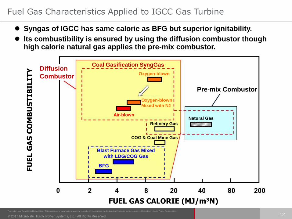
Fuel Gas Characteristics Applied to IGCC Gas Turbine
12
FUEL GAS CALORIE (MJ/m3N)
FU
EL G
AS
CO
MB
US
TIB
ILIT
Y Syngas of IGCC has same calorie as BFG but superior ignitability.
Its combustibility is ensured by using the diffusion combustor though high calorie natural gas applies the pre-mix combustor.
Natural Gas
Refinery Gas
COG & Coal Mine Gas
Blast Furnace Gas Mixed
with LDG/COG Gas
BFG
Pre-mix Combustor
Coal Gasification SyngGas
Oxygen-blown
Oxygen-blown
Mixed with N2
Air-blown
Diffusion
Combustor

© 2017 Mitsubishi Hitachi Power Systems, Ltd. All Rights Reserved.
Proprietary and Confidential Information. This document or information cannot be reproduced, transmitted, or disclosed without prior written consent of Mitsubishi Hitachi Power Systems,Ltd.
13
1. Introduction
2. Features of IGCC system
3. Development
4. Commercial Plant
5. Examples of Feasibility Study
6. Future Applications
7. Conclusion

© 2017 Mitsubishi Hitachi Power Systems, Ltd. All Rights Reserved.
Proprietary and Confidential Information. This document or information cannot be reproduced, transmitted, or disclosed without prior written consent of Mitsubishi Hitachi Power Systems,Ltd.
IGCC/Gasification Technology Development
14
1986
100
Ou
tpu
t (M
W)
200
300
400
500
600
700
0Year92 94 96 98 2000 02 04 06 08 10 12 14 16 18 20 22 24 26
Fukushima Hirono & Nakoso
IGCC Project (2020~)
Joban Joint Power Co.LTD
Nakoso #10
(Demo. 2007-, Commercial 2013-)
EAGLE Pilot Plant
(2002-2013, 2017-)HYCOL Pilot Plant
(1991-1993)
200 t/d Nakoso Pilot Plant (1991-)
2888 90
Osaki CoolGen Project
(Demo. 2017-)
Air-blown IGCC
Oxygen-blown IGCC
Sponsored by NEDO
Sponsored by METI
Sponsored by NEDO
Sponsored by METI and NEDO
Accumulated Original Technologies through Long Term R&D
Activities since Early 1980’s
Achievement of High Reliability in Operation at Nakoso 250MW
Demo. Plant
Osaki CoolGen, is in the course of demonstration.
© 2017 Mitsubishi Hitachi Power Systems, Ltd. All Rights Reserved.
Proprietary and Confidential Information. This document or information cannot be reproduced, transmitted, or disclosed without prior written consent of Mitsubishi Hitachi Power Systems,Ltd.
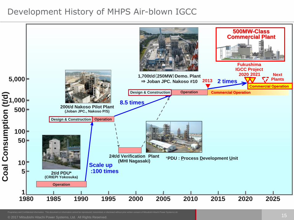
Development History of MHPS Air-blown IGCC
15
1,700t/d(250MW)Demo. Plant
⇒ Joban JPC. Nakoso #10
1980 1990 2000 20101985 1995 20051
10
100
1,000
5
50
500
5,000
Co
al C
on
su
mp
tio
n (
t/d
)
2t/d PDU*(CRIEPI Yokosuka)
200t/d Nakoso Pilot Plant (Joban JPC., Nakoso P/S)
Scale up :100 times
8.5 times
Design & Construction Operation
Operation
Design & Construction
2015
24t/d Verification Plant(MHI Nagasaki)
Operation Commercial Operation
2020 2025
▼2013
500MW-Class Commercial Plant
Fukushima IGCC Project
NextPlants
Commercial Operation
20212020
2 times
*PDU : Process Development Unit

© 2017 Mitsubishi Hitachi Power Systems, Ltd. All Rights Reserved.
Proprietary and Confidential Information. This document or information cannot be reproduced, transmitted, or disclosed without prior written consent of Mitsubishi Hitachi Power Systems,Ltd.
Development History of MHPS Oxygen-blown IGCC
16
PDU test(Process Development Unit)
(1t/d 1981~1985 at Katsuta)
HYCOL pilot test (Hydrogen from Coal)
(50t/d 1990~1993 at Sodegaura)
EAGLE pilot test
(Coal Energy Application for Gas, Liquid and Electricity)
(150t/d 2002~2013, 10t/d 2017- at Wakamatsu)
OCG Project (Osaki CoolGen)
(1,180t/d 2017~ Demo. Operation
onward at Osakikamijima-cho)
× 3Scale-up
× 8Scale-up
(inside the grounds of Chugoku Electric’s Osaki Power Station)
:Osaki CoolGen Project
Demonstration Test Area (First step)
Inside grounds of
Chugoku Electric’s
Osaki Power Station
Photos courtesy of Osaki CoolGen Corp.
© 2017 Mitsubishi Hitachi Power Systems, Ltd. All Rights Reserved.
Proprietary and Confidential Information. This document or information cannot be reproduced, transmitted, or disclosed without prior written consent of Mitsubishi Hitachi Power Systems,Ltd.
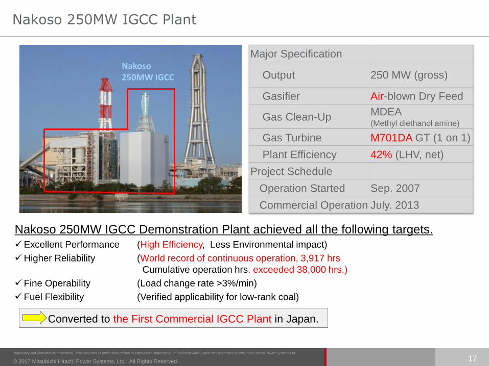
Nakoso 250MW IGCC Plant
Nakoso250MW IGCC
Major Specification
Output 250 MW (gross)
Gasifier Air-blown Dry Feed
Gas Clean-UpMDEA(Methyl diethanol amine)
Gas Turbine M701DA GT (1 on 1)
Plant Efficiency 42% (LHV, net)
Project Schedule
Operation Started Sep. 2007
Commercial Operation July. 2013
Nakoso 250MW IGCC Demonstration Plant achieved all the following targets.Excellent Performance (High Efficiency, Less Environmental impact)
Higher Reliability (World record of continuous operation, 3,917 hrs
Cumulative operation hrs. exceeded 38,000 hrs.)
Fine Operability (Load change rate >3%/min)
Fuel Flexibility (Verified applicability for low-rank coal)
Converted to the First Commercial IGCC Plant in Japan.
17

© 2017 Mitsubishi Hitachi Power Systems, Ltd. All Rights Reserved.
Proprietary and Confidential Information. This document or information cannot be reproduced, transmitted, or disclosed without prior written consent of Mitsubishi Hitachi Power Systems,Ltd.
Achievements of Nakoso 250MW IGCC Plant
Targets Achievements Note
Performance
Output (Gross)(Net)
250MW
220MW
250MW
225MW
Efficiency (Net, LHV) > 42.0% 42.9%
Carbon Conversion > 99.9% > 99.9%
Emission(@dry, 16%O2)
SOx NOx Dust
< 8 ppm< 5 ppm
< 4 mg/m3N
1.0 ppm3.4 ppm
< 0.1 mg/m3N
Operational
Flexibility
Coal KindsBituminous
Sub-bituminous
Chinese, Canadian2 US (including PRB)
3 Indonesian (Adaro, etc.)Colombian, 2 Russian
10 kinds of coal in total6 Sub-bituminous4 Bituminous
have been used.
Start-up Time < 18 hr 15 hr
Minimum Load 50% 36%
Ramping Rate 3%/min 3%/min
ReliabilityLong-term Continuous Operation
2,000 hr 3,917 hrCumulative operating hours :> 38,000 hrs.
18

© 2017 Mitsubishi Hitachi Power Systems, Ltd. All Rights Reserved.
Proprietary and Confidential Information. This document or information cannot be reproduced, transmitted, or disclosed without prior written consent of Mitsubishi Hitachi Power Systems,Ltd.
Osaki CoolGen Project
19
Sponsored by METI and NEDO
Major Specification
Output 166 MW (gross)
GasifierOxygen-blown Single-chamber Two-stage
Entrained-flow
Gas Clean-Up MDEA (Methyldiethanol Amine)
Gas Turbine H-100 GT (1 on 1)
Plant Efficiency 40.5% (HHV, net) (42.7%(LHV, net))
Project Schedule
Construction Started March 2013
Demo. Operation Started March 2017 (First step)
Rendering Image
Air
Coal
Syngas(H2,CO)
Heat recovery steam generator
Air Stack
Gasifier
CO shiftreactor
CO2CaptureUnit
H2
CO2,H2
ガス化
Air separation unit
Steam turbine
Gas turbine
Generator
First step:Oxygen-blown IGCC
Second step:IGCC with CO2 Capture
IGCC:166MW(Coal feed rate:1180t/d)Gasifier : Single Chamber with Two Stages Spiral Flow Gasifier
Third step:IGFC with CO2 Capture
FC
Oxygen
CO2Transport and Storage(*3)
Add installing CO shift reactor
and CO2 capture unit
(*3) CO2 Transportation and Storage are outside of the Osaki CoolGen Project.
:Osaki CoolGen Project
Demonstration Test Area (First step)
Inside grounds of
Chugoku Electric’s
Osaki Power Station
Photos courtesy of Osaki CoolGen Corp.
(*1)(*1) Demo. Operation of Second step
will start in FY 2019
(*2) (*2) Demo. Operation of Third step
will start in FY 2021

© 2017 Mitsubishi Hitachi Power Systems, Ltd. All Rights Reserved.
Proprietary and Confidential Information. This document or information cannot be reproduced, transmitted, or disclosed without prior written consent of Mitsubishi Hitachi Power Systems,Ltd.
Osaki CoolGen Project
20
Rendering Image
FY 2012 2013 2014 2015 2016 2017 2018
Schedule for oxygen-blown IGCC demonstration (First step)
DemonstrationDetailed design and construction of
oxygen-blown IGCC units and facilities
:Osaki CoolGen Project
Demonstration Test Area (First step)
Inside grounds of
Chugoku Electric’s
Osaki Power Station
Photos courtesy of Osaki CoolGen Corp.A crane lifted the gasifier and
placed it on a dolly on a track.
The gasifier was
erected vertically
and moved up to
a designed position.
© 2017 Mitsubishi Hitachi Power Systems, Ltd. All Rights Reserved.
Proprietary and Confidential Information. This document or information cannot be reproduced, transmitted, or disclosed without prior written consent of Mitsubishi Hitachi Power Systems,Ltd.
21
1. Introduction
2. Features of IGCC system
3. Development
4. Commercial Plant
5. Examples of Feasibility Study
6. Future Applications
7. Conclusion
© 2017 Mitsubishi Hitachi Power Systems, Ltd. All Rights Reserved.
Proprietary and Confidential Information. This document or information cannot be reproduced, transmitted, or disclosed without prior written consent of Mitsubishi Hitachi Power Systems,Ltd.
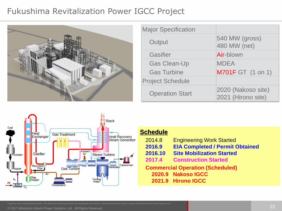
Fukushima Revitalization Power IGCC Project
Major Specification
Output540 MW (gross)
480 MW (net)
Gasifier Air-blown
Gas Clean-Up MDEA
Gas Turbine M701F GT (1 on 1)
Project Schedule
Operation Start2020 (Nakoso site)
2021 (Hirono site)
22
Schedule
2014.8 Engineering Work Started
2016.9 EIA Completed / Permit Obtained
2016.10 Site Mobilization Started
2017.4 Construction Started
Commercial Operation (Scheduled)
2020.9 Nakoso IGCC
2021.9 Hirono IGCC

© 2017 Mitsubishi Hitachi Power Systems, Ltd. All Rights Reserved.
Proprietary and Confidential Information. This document or information cannot be reproduced, transmitted, or disclosed without prior written consent of Mitsubishi Hitachi Power Systems,Ltd.
Fukushima Revitalization Power IGCC Project
23
Production of Pressure Vessel for IGCC Plants Now Underway
© 2017 Mitsubishi Hitachi Power Systems, Ltd. All Rights Reserved.
Proprietary and Confidential Information. This document or information cannot be reproduced, transmitted, or disclosed without prior written consent of Mitsubishi Hitachi Power Systems,Ltd.
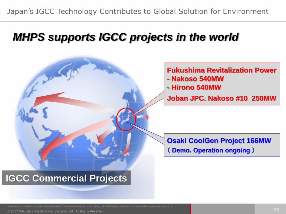
IGCC Commercial Projects
Fukushima Revitalization Power
- Nakoso 540MW
- Hirono 540MW
Joban JPC. Nakoso #10 250MW
Osaki CoolGen Project 166MW
( Demo. Operation ongoing )
MHPS supports IGCC projects in the world
24
Japan’s IGCC Technology Contributes to Global Solution for Environment

© 2017 Mitsubishi Hitachi Power Systems, Ltd. All Rights Reserved.
Proprietary and Confidential Information. This document or information cannot be reproduced, transmitted, or disclosed without prior written consent of Mitsubishi Hitachi Power Systems,Ltd.
25
1. Introduction
2. Features of IGCC system
3. Development
4. Commercial Plant
5. Examples of Feasibility Study
6. Future Applications
7. Conclusion

© 2017 Mitsubishi Hitachi Power Systems, Ltd. All Rights Reserved.
Proprietary and Confidential Information. This document or information cannot be reproduced, transmitted, or disclosed without prior written consent of Mitsubishi Hitachi Power Systems,Ltd.
Examples of Feasibility Study ~ Thailand
Approx. 500km
Item Specification
User EGAT
Site Mae Moh PP (For #8-#9 Replacement)
Output 500MW-class IGCC×1unit
Fuel Mae Moh Lignite
Main
Component
Air-blown Gasifier
M701F Type Gas Turbine☓1
IGCC Principal Specification
View of Existing Plant / Coal Mine
Existing
Plant
Coal
Mine
Schedule
2015/4~2016/3:NEDO* Feasibility Study
2015/12 :Mae Moh Lignite Gasification Verification in Nagasaki, Japan
2016/2 :Reported Feasibility Study Result to EGAT
Bangkok
Thailand
Mae Moh
26
(*) NEDO : New Energy and Industrial Technology
Development Organization

© 2017 Mitsubishi Hitachi Power Systems, Ltd. All Rights Reserved.
Proprietary and Confidential Information. This document or information cannot be reproduced, transmitted, or disclosed without prior written consent of Mitsubishi Hitachi Power Systems,Ltd.
Examples of Feasibility Study ~ Poland
27
Item Specification
User EW (Enea Wytwarzanie sp. z o.o.)
Site Kozienice Power Plant or
Green Field Investment
Output 500MW-class IGCC×1unit
Fuel Bogdanka Coal
Main
Component
Air-blown Gasifier
M701F Type Gas Turbine☓1
IGCC Principal Specification
Schedule
2015/10~2016/6: NEDO* Feasibility Study
2016/4 :Bogdanka Coal Gasification Verification in Nagasaki, Japan
2016/6 :Reported Feasibility Study Result
to EW
Poland
Kozienice
Warsaw
(*) NEDO : New Energy and Industrial Technology
Development Organization
Approx. 70km
View of Existing Plant

© 2017 Mitsubishi Hitachi Power Systems, Ltd. All Rights Reserved.
Proprietary and Confidential Information. This document or information cannot be reproduced, transmitted, or disclosed without prior written consent of Mitsubishi Hitachi Power Systems,Ltd.
View of Gasification Verification Facilities
28
Coal
Feeding
Facilities
Gasifier
Control Room
The gasification verification of each coal was conducted by using the gasification verification facilities at MHI Research & Innovation Center, Nagasaki.
© 2017 Mitsubishi Hitachi Power Systems, Ltd. All Rights Reserved.
Proprietary and Confidential Information. This document or information cannot be reproduced, transmitted, or disclosed without prior written consent of Mitsubishi Hitachi Power Systems,Ltd.
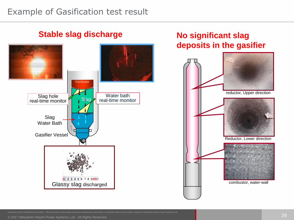
Example of Gasification test result
29
Slag
Slag
Water Bath
Slag holereal-time monitor
Gasifier Vessel
Combustor
Water bathreal-time monitor
Stable slag discharge
Glassy slag discharged
No significant slag
deposits in the gasifier
reductor, Upper direction
Reductor, Lower direction
combustor, water-wall

© 2017 Mitsubishi Hitachi Power Systems, Ltd. All Rights Reserved.
Proprietary and Confidential Information. This document or information cannot be reproduced, transmitted, or disclosed without prior written consent of Mitsubishi Hitachi Power Systems,Ltd.
Ash Fluid Temperature [deg-C]
Fu
el
Rati
o
(=F
ixed
Carb
on
/ V
ola
tile
)
MHPS IGCC has successfully operated in using world-wide variety of coal.
Australian CoalAmerican CoalChinese CoalSouth African CoalIndonesian CoalJapanese CoalCanadian CoalRussian Coal Colombian CoalThai CoalPolish Coal
30
Variety of Coal Experience and Capability
Polish Coal
Thai Coal

© 2017 Mitsubishi Hitachi Power Systems, Ltd. All Rights Reserved.
Proprietary and Confidential Information. This document or information cannot be reproduced, transmitted, or disclosed without prior written consent of Mitsubishi Hitachi Power Systems,Ltd.
31
1. Introduction
2. Features of IGCC system
3. Development
4. Commercial Plant
5. Examples of Feasibility Study
6. Future Applications
7. Conclusion
© 2017 Mitsubishi Hitachi Power Systems, Ltd. All Rights Reserved.
Proprietary and Confidential Information. This document or information cannot be reproduced, transmitted, or disclosed without prior written consent of Mitsubishi Hitachi Power Systems,Ltd.
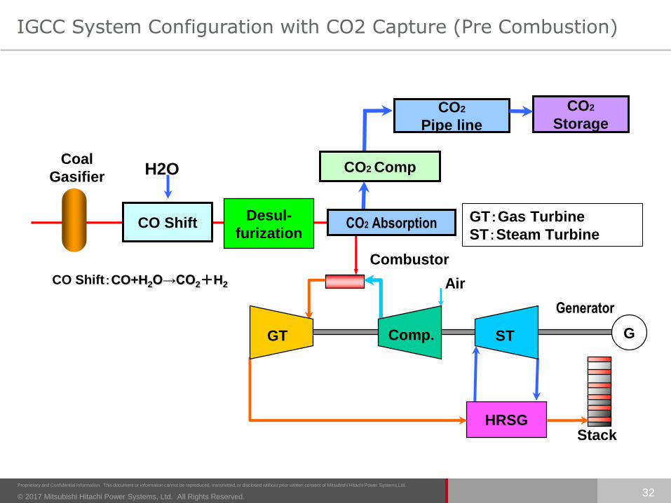
IGCC System Configuration with CO2 Capture (Pre Combustion)
32
Stack
G
Combustor
HRSG
STComp.GT
Desul-
furizationCO Shift
CO Shift:CO+H2O→CO2+H2
H2O
Air
Generator
GT:Gas Turbine
ST:Steam Turbine
Coal
GasifierCO2 Comp
CO2 Absorption
CO2
Pipe line
CO2
Storage
© 2017 Mitsubishi Hitachi Power Systems, Ltd. All Rights Reserved.
Proprietary and Confidential Information. This document or information cannot be reproduced, transmitted, or disclosed without prior written consent of Mitsubishi Hitachi Power Systems,Ltd.
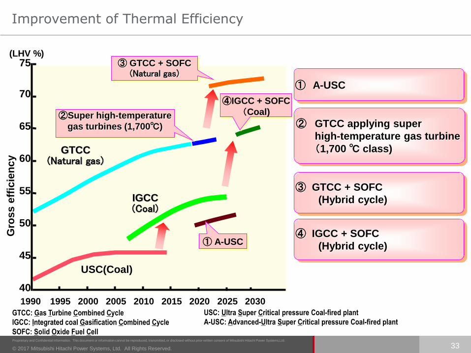
Improvement of Thermal Efficiency
33
Gro
ss e
ffic
ien
cy
40
45
50
55
60
65
70
1990 1995 2000 2005 2010 2015
USC(Coal)
(LHV %)75
2020
GTCC(Natural gas)
④IGCC + SOFC
(Coal)②Super high-temperature
gas turbines (1,700℃)
③ GTCC + SOFC(Natural gas)
② GTCC applying super
high-temperature gas turbine
(1,700 ℃ class)
③ GTCC + SOFC
(Hybrid cycle)
GTCC: Gas Turbine Combined Cycle
IGCC: Integrated coal Gasification Combined Cycle
SOFC: Solid Oxide Fuel Cell
USC: Ultra Super Critical pressure Coal-fired plant
A-USC: Advanced-Ultra Super Critical pressure Coal-fired plant
2025 2030
① A-USC
① A-USC
IGCC(Coal)
④ IGCC + SOFC
(Hybrid cycle)
© 2017 Mitsubishi Hitachi Power Systems, Ltd. All Rights Reserved.
Proprietary and Confidential Information. This document or information cannot be reproduced, transmitted, or disclosed without prior written consent of Mitsubishi Hitachi Power Systems,Ltd.
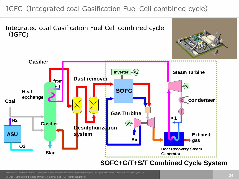
IGFC(Integrated coal Gasification Fuel Cell combined cycle)
34
Inverter
SOFC
*1
SOFC+G/T+S/T Combined Cycle System
Steam Turbine
Exhaust
gas
Heat Recovery Steam
Generator
Air
Gas Turbine
condenser
Gasifier
Heat
exchanger
Dust remover
Desulphurization
system
Coal
Slag
Gasifier
from*1
ASU
O2
N2
Integrated coal Gasification Fuel Cell combined cycle(IGFC)

© 2017 Mitsubishi Hitachi Power Systems, Ltd. All Rights Reserved.
Proprietary and Confidential Information. This document or information cannot be reproduced, transmitted, or disclosed without prior written consent of Mitsubishi Hitachi Power Systems,Ltd.
35
1. Introduction
2. Features of IGCC system
3. Development
4. Commercial Plant
5. Examples of Feasibility Study
6. Future Applications
7. Conclusion

© 2017 Mitsubishi Hitachi Power Systems, Ltd. All Rights Reserved.
Proprietary and Confidential Information. This document or information cannot be reproduced, transmitted, or disclosed without prior written consent of Mitsubishi Hitachi Power Systems,Ltd.
Conclusion
The 250MW Air-blown IGCC demonstration plant, operating now as Joban JPC Nakoso #10 - the first IGCC commercial plant in Japan, successfully achieved all of its purpose and targets.
MHPS has started Air-blown IGCC commercial projects represented by Nakoso & Hirono IGCC Powers 540MW×2 aiming at CO2 reduction by 10-20%.
Oxygen-blown IGCC, Osaki CoolGen, is in the course of demonstration.
MHPS expects that our IGCC technology will contribute to the solution of energy and environmental issues in the world, with full reflection of the accumulatedexperiences at IGCC projects in Japan.
36
© 2017 Mitsubishi Hitachi Power Systems, Ltd. All Rights Reserved.
Proprietary and Confidential Information. This document or information cannot be reproduced, transmitted, or disclosed without prior written consent of Mitsubishi Hitachi Power Systems,Ltd.
Mitsubishi Hitachi Power Systems
37


