Intel is a trademark of Intel Corporation in the U.S. and/or other countries.
Cloud EPC Demo System Architecture
This document describes the system architecture of the Intel-Tieto Cloud EPC project. The purpose of this project is to demonstrate feasibility of implementing a LTE EPC network using open source SW components and Intel Multicore HW platform. The system has been constructed to be elasticity and flexible by having a scalable system SW architecture with the option to be deployed in a virtualized environment. This is shown in a functional demo part. Special attention has been taken to analyze the packet processing performance by constructing and evaluating a load balancer that can run either software or with hardware support. This is displayed in a performance demo part. The purpose of the demos are:
Functional demo: Demonstrate dynamic allocation of EPC functionality on CPU cores and illustrate how more or less cores are being used as traffic requirements scale up and down. This dynamic behaviour can be used to scale power requirements and to and in particular condense EPC functionality on fewer HW systems during off-peak hours while still retaining the possibility to scale during peak hours.
Performance demo: Demonstrate the capability of state-of-the-art multi-core Intel processors wrt. to usage in LTE EPC systems. The demo shows the benefits of using the Intel DPDK together with a high performance carrier grade IP stack (Titeo TIP-stack). Demo is shown using both SW based and HW based load distribution respectively.
Cloud EPC Demo System Architecture Final, v1.0 Tieto Cloud EPC Team 2012-02-23
2.1.2.1 TIP Packet Scheduler ............................................................................... 18 2.1.2.2 TIP Fastpath ............................................................................................. 18
2.2 Usermode Architecture ................................................................................................... 19 2.2.1 Poll-mode NIC and Main Loop ............................................................................... 20 2.2.2 Internal Socket API ................................................................................................ 20 2.2.3 Scheduling Between IP-stack and Application........................................................ 20
Intel is a trademark of Intel Corporation in the U.S. and/or other countries.
1 Functional Demo
1.1 Overview
The Functional demo software is intended for evaluation of cloud-like features in Evolved Packet Core network. These features include dynamic load balancing of selected network nodes and power management. Due to the experimental nature of the demo, functionality is prioritized over performance and full 3GPP-compliancy.
1.2 Setup
The following figure presents the demo setup and dependencies. The demonstration environment consists of three PC-machines:
CloudEPC runs an all-IP telecom core network. It hosts the needed network nodes (MME, SGW, PGW, HSS) and dynamically spawns new instances of gateways or MME’s if needed. It also shuts down instances if the traffic amount decreases.
CloudEPC_Simulator runs eNodeB-functionalities and simulates end users to generate signaling and user plane traffic to the EPC network.
CloudEPC_Serving_Network simulates serving network, in practice hosts a TFTP-server from where the end users fetch files to generate user plane traffic.
Cloud EPC Demo System Architecture Final, v1.0 Tieto Cloud EPC Team 2012-02-23
Intel is a trademark of Intel Corporation in the U.S. and/or other countries.
Cloud EPCLoad
balancer
CloudEPC
MME SGW PGW
switch
Traffic Simulator Serving Network Simulator
Cloud EPCStatistics
PGW
PGW
PGW
PGW
PGW
Cloud EPC Demo
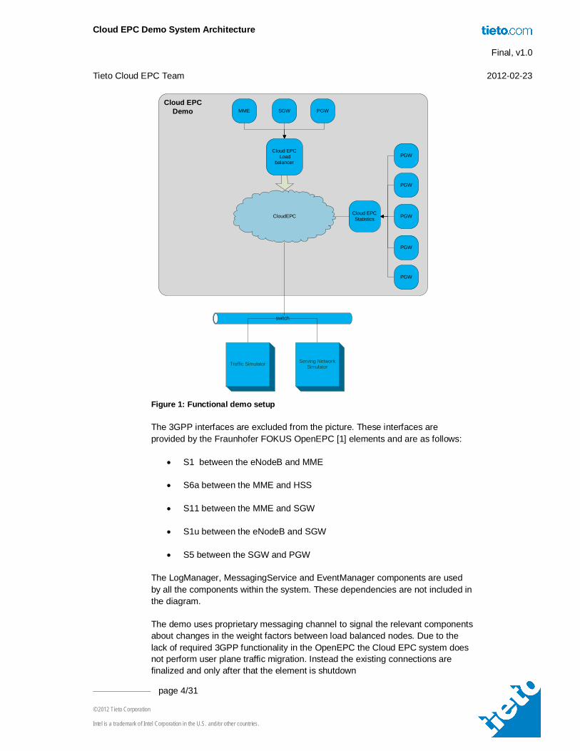
Figure 1: Functional demo setup
The 3GPP interfaces are excluded from the picture. These interfaces are provided by the Fraunhofer FOKUS OpenEPC [1] elements and are as follows:
S1 between the eNodeB and MME
S6a between the MME and HSS
S11 between the MME and SGW
S1u between the eNodeB and SGW
S5 between the SGW and PGW
The LogManager, MessagingService and EventManager components are used by all the components within the system. These dependencies are not included in the diagram.
The demo uses proprietary messaging channel to signal the relevant components about changes in the weight factors between load balanced nodes. Due to the lack of required 3GPP functionality in the OpenEPC the Cloud EPC system does not perform user plane traffic migration. Instead the existing connections are finalized and only after that the element is shutdown
Cloud EPC Demo System Architecture Final, v1.0 Tieto Cloud EPC Team 2012-02-23
Intel is a trademark of Intel Corporation in the U.S. and/or other countries.
Tieto Networked Device Platform (TNDP) is running on each blade that is active in the system. The TNDP instance is called a node. Within the whole system a single node is called the node manager. In the Cloud EPC system the node manager is always located in the O&M blade.
1.3 Software components
The functional demo is built using OpenEPC software that has been developed by Fraunhofer FOKUS. Tieto has developed the OpenEPC further and built a system which enables a cloud-like functionality of the EPC core network. The software components and their roles are introduced in this chapter.
1.3.1 Load balancer
Load balancer is responsible for managing the application level resources within the Cloud EPC system. Load balancer initiates the second level startup sequence where the initial EPC elements are started.
When the system is running the load balancer obtains the system statistics via the statistics library. The following measurements are used:
Total CPU load per blade. This is calculated as an average of core loads.
EPC element statistics:
o MME: Transactions per second
o SGW and PGW: Throughput Mbits per second
The statistics are updated once in every second. After the update the load balancer will evaluate all the predefined rules. These rules are defined in an XML file, which is specified as a startup parameter for the load balancer. The rule file defines a set of triggers for each element. The supported trigger types are:
Load – specified task is executed by the load balancer if the EPC element or blade CPU load average is either above or below given threshold.
Min-max-diff – a task is executed by the load balancer if the difference between the largest load and the smallest grows above given threshold.
If a specific trigger fires then a predefined task is executed. For the EPC elements the tasks are:
Launch task will start a new element instance. The element type is specified in the rules i.e. each element will have their own set of rules.
Kill task will stop the define element.
Load-balance task will send a new weight vector to the traffic simulator so it can adjust the traffic parameters accordingly.
Cloud EPC Demo System Architecture Final, v1.0 Tieto Cloud EPC Team 2012-02-23
Intel is a trademark of Intel Corporation in the U.S. and/or other countries.
1.3.1.1 CPU core load balancing
CPU core load balancing triggers are defined in an XML file. All the CPU cores are managed by the same rules. The default values are 50% for the lower threshold and 80% for the upper.
The CPU core load management measures the CPU load once per second for decision making purposes. The average of five consecutive measurements is used to decide when to start/stop CPU cores. When the average load of online CPU cores exceeds the upper threshold, a new core is activated. When the average load of (online CPU cores -1) would be under lower threshold, one of the cores is put offline.
1.3.2 Hardware Manager
Hardware Manager component provides services for:
HW object run time add-on service
HW object configuration
HW object supervision and monitoring of machines, CPUs and other resources
In the Cloud EPC the Hardware manager is extended with the CPU plugin that is responsible for collecting CPU load information and controlling the CPU states.The CPU plugin will activate / de-activate CPU cores based on the predefined load thresholds.
Hardware manager has a non-public message interface and the relevant actions like CPU core activation are signaled with events.
1.3.3 Responsibilities
The Hardware manager is responsible for:
Collecting CPU load information.
Activating and deactivating CPU cores based on the load information.
Controlling the CPU states.
1.3.4 Application Manager
Application manager is responsible for handling the EPC element life cycle. It receives element start and stop requests from the load balancer and acts accordingly. In addition it is application manager’s responsibility to periodically collect statistics information from the currently running EPC elements.
Cloud EPC Demo System Architecture Final, v1.0 Tieto Cloud EPC Team 2012-02-23
Intel is a trademark of Intel Corporation in the U.S. and/or other countries.
1.3.4.1 Responsibilities
Application manager is responsible for:
Starting an EPC element based on the requests from the load balancer.
Stopping an EPC element based on the requests from the load balancer.
Notifying the load balancer after the request has been completed.
Periodically collecting the counters from the EPC elements that the particular application manager is responsible for.
1.3.5 Statistics
Statistics implementation in the system is divided into two separate components. The statistics collector implements a service for gathering and storing system status data from hardware and status data provided by other components. The statistics library provides convenience functions for the other components to easily access the measurements.
1.3.5.1 Responsibilities
Statistics component is responsible for providing counter data from EPC elements. The MME counters are based on the executed operations (both detach and attach). For the gateways the amount of payload data is measured.
1.3.6 Traffic Simulator
Traffic simulator implements the three demonstration scenarios for the Cloud EPC:
Attach / detach loop
User plane traffic with fixed size payload.
User plane traffic with variable size payload.
Traffic simulator generates both the signaling and user plane traffic used to load the Cloud EPC system. The traffic simulator is divided into two parts:
Actual simulator controlling the traffic load and other parameters.
eNodeB simulator from the OpenEPC. The eNodeB provides the required protocol stacks and 3GPP interfaces.
The communication between the simulator and eNodeB is implemented using the Unix socket interface provided by the OpenEPC.
Cloud EPC Demo System Architecture Final, v1.0 Tieto Cloud EPC Team 2012-02-23
Intel is a trademark of Intel Corporation in the U.S. and/or other countries.
The user interface provides the required control parameters to the simulator. In addition load balancer provides a weight vector to the simulator. The vector can be used to adjust the traffic flow.
The actual traffic is generated using a weighted round robin algorithm.
1.3.6.1 Responsibilities
Traffic simulator is responsible for:
Implementing the scenarios.
Providing the 3GPP interface for eNodeB.
Controlling the traffic based on the user input from the user interface.
Controlling the traffic based on the adjustments from the load balancer.
1.3.7 User interface
The user interface is shared between the two demos: functional and performance.
Graphical user interface (GUI) can be separated to three different subsystems: the graphical part representing the views, the engine and the messaging interface.
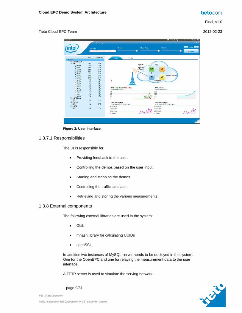
The views for the GUI are implemented using the Qt framework and the same application is used for both Functional and Performance demo. In the header part, user can choose between the Functional and Performance demo by selecting the appropriate demo from the menu. On top of the window, there is a control part from which the user can start and stop scenarios and handle the scenario parameters. The overview of the hardware is represented in the tree view in the left hand side. Depending on the selection of the tree, the right hand side content area changes to show more detailed info and graphs about the selected tree item.
The engine is responsible for demo and scenario handling and data managing to the graphical views. It handles the start up and shutdown of the demos and scenarios. The engine utilizes the messaging interface and its command line tools for communicating towards the traffic simulator.
The engine is also responsible for reading the measurement data, which is stored to MySQL databases: one database for the Functional demo and one database for the Performance demo statistics.
Messaging interface provides interface for controlling all machines in the demo and fetching all available statistics from each machine by using TNDP messaging interface. All fetched data is saved to MySQL database.
Figure 2: User interface shows an example of the functional demo GUI logical view.
Cloud EPC Demo System Architecture Final, v1.0 Tieto Cloud EPC Team 2012-02-23
Intel is a trademark of Intel Corporation in the U.S. and/or other countries.
Figure 2: User interface
1.3.7.1 Responsibilities
The UI is responsible for:
Providing feedback to the user.
Controlling the demos based on the user input.
Starting and stopping the demos.
Controlling the traffic simulator.
Retrieving and storing the various measurements.
1.3.8 External components
The following external libraries are used in the system:
GLib
mhash library for calculating UUIDs
openSSL
In addition two instances of MySQL server needs to be deployed in the system. One for the OpenEPC and one for relaying the measurement data to the user interface.
A TFTP server is used to simulate the serving network.
Cloud EPC Demo System Architecture Final, v1.0 Tieto Cloud EPC Team 2012-02-23
Intel is a trademark of Intel Corporation in the U.S. and/or other countries.
1.4 Demonstration scenarios
The functional demo scenarios are implemented as follows.
1.4.1 MME load balancing
In this scenario Simulator (Load generator) does attachments to users until it reaches the amount of maximum users (selected by Users -slider) and then detaches all attached users and starts from the beginning again.
"Users" slider adjusts the maximum number of concurrent users from 1 to 91.
“Attach rate” adjusts the delay between attaches in milliseconds from 1050 to 50.
1.4.2 SGW load balancing
In this scenario Simulator does the following procedure concurrently to the maximum number of users selected by the Users-slider:
attach, start fetching file, when file is fetched, detach
"Users" slider adjusts the maximum number of concurrent users from 1 to 91.
“Attach rate” adjusts the delay between attaches in milliseconds from 1050 to 50.
“File size” slider is not visible in this scenario. File size is fixed (1Mb).
1.4.3 EPC load balancing
Same as scenario “SGW load balancing”, but the file size is configurable between 1Mb and 100Mb from the “File size” slider.
"Users" slider adjusts the maximum number of concurrent users from 1 to 91.
“Attach rate” adjusts the delay between attaches in milliseconds from 1050 to 50.
“File size” slider adjusts the file size between 1Mb to 100Mb.
1.5 System startup
The Cloud EPC system is started by Bash script start_cloud_epc.sh. The following actions are done by the script:
Cloud EPC Demo System Architecture Final, v1.0 Tieto Cloud EPC Team 2012-02-23
Intel is a trademark of Intel Corporation in the U.S. and/or other countries.
1. Start the TNDP instance in every machine which is defined to be operational during the system startup. This is achieved by running eSW_platform.sh start command via SSH.
2. Start the traffic simulator.
3. Start the HSS.
4. Start the eDHCP
5. Start the DNS
6. Start the load balancer.
After the script has started the load balance the script execution ends and the load balancer takes over the system initialization. The following actions are done by the load balancer:
1. Verify the node manager functionality.
2. After the load balancer receives acknowledgement the load balancer checks that all the critical components are up and running.
3. Load balancer starts 1st MME instance.
4. Load balancer starts 1st SGW instance.
5. Load balancer starts 1st PGW instance.
6. After the Load balancer receives the acknowledgement for each of the three element it notifies the UI that the system is up and running.
1.5.1 EPC element startup
Each EPC element active within the system is launched by the application manager. In order to correctly configure the EPC element the application manager:
1. Creates a database for the element.
2. Configures the IP address to the VLAN associated with the correct network interface.
3. Creates an XML configuration file specifying the database and IP address details.
4. Launches the EPC element
Cloud EPC Demo System Architecture Final, v1.0 Tieto Cloud EPC Team 2012-02-23
Intel is a trademark of Intel Corporation in the U.S. and/or other countries.
1.6 System shutdown
The system shutdown is initiated from the user interface. The shutdown is implemented as follows:
1. The UI will notify the simulator to stop all traffic.
2. The UI will notify load balancer that the system is being shutdown. The load balancer stops doing any load balancing actions.
3. UI receives an event from the simulator that the traffic is now stopped.
4. UI requests load balancer to shutdown the EPC element.
5. Load balancer forwards the stop application requests to every application manager.
6. After the load balancer has received all the acknowledgement events from the application managers it notifies the UI that shutdown can continue.
7. UI commences system reboot on all target machines.
1.7 Interfaces and addressing
Due to the OpenEPC requirement each machine running the OpenEPC elements will have five VLAN interfaces namely: net_a, net_b, net_c, net_d and mgmt. Each of the machines running OpenEPC has two physical interfaces that are shared by the above mentioned VLAN’s. IP addressing is illustrated in Figure 3: Interfaces and addressing.
Cloud EPC Demo System Architecture Final, v1.0 Tieto Cloud EPC Team 2012-02-23
Intel is a trademark of Intel Corporation in the U.S. and/or other countries.
Figure 3: Interfaces and addressing
Each of the OpenEPC elements has a distinct IP address. The address ranges for the elements that are load balanced are defined as follows:
SGW: 192.168.4.20 – 192.168.4.29
PGW: 192.168.2.10 – 192.168.2.19
The addressing within the Cloud EPC system is two-fold. Externally the system exposes a set of IP addresses and ports. These are used by the user interface and the traffic simulator.
Internally the system uses Universally Unique Identifiers (UUID). The UUID is represented by 32 hexadecimal digits, displayed in 5 groups separated by hyphens, in the form 8-4-4-4-12 for a total of 36 characters.
The node manager has a special UUID, all zeroes, and it is known by all the components in the system.
1.8 Virtualization option
With the virtualization option the functional demo can support multiple instances of the same core network, enabling multi-tenancy support for network operators. Use of virtualization gives possibilities to reduces both the capital and the operating expenses by for example saving in energy costs, using shared hardware resources and simplified deployment of new networks. The virtualization solution of functional demo is illustrated in Figure 4.
net_a 192.168.1.Xnet_b 192.168.2.Xnet_c 192.168.1X.X DHCP RANGE 129->254net_d 192.168.4.Xmgmt 192.168.254.X
MME
SGW
eNB
PGW
HSS
net_d.8X
net_d.2X
net_d.90
Mgmt.8X
Mgmt.1XMgmt.2X
Mgmt.90
Mgmt.40
net_d VLAN500
mgmt VLAN100
net_a VLAN200
LoadGen
net_c VLAN400
net_c.1X.XTFTPserver
net_c.29
net_b VLAN300
net_b.2X net_b.1X
net_a.1X
net_a.40
net_a.50
Cloud EPC Demo System Architecture Final, v1.0 Tieto Cloud EPC Team 2012-02-23
Intel is a trademark of Intel Corporation in the U.S. and/or other countries.
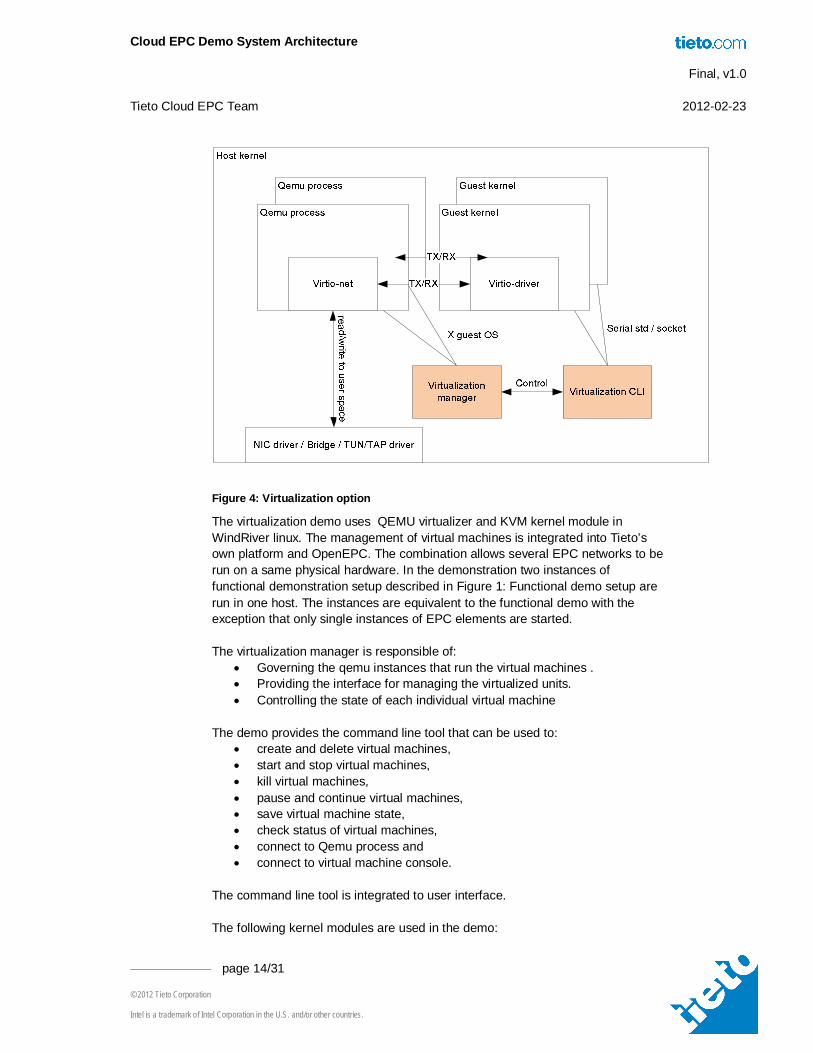
Figure 4: Virtualization option
The virtualization demo uses QEMU virtualizer and KVM kernel module in WindRiver linux. The management of virtual machines is integrated into Tieto’s own platform and OpenEPC. The combination allows several EPC networks to be run on a same physical hardware. In the demonstration two instances of functional demonstration setup described in Figure 1: Functional demo setup are run in one host. The instances are equivalent to the functional demo with the exception that only single instances of EPC elements are started. The virtualization manager is responsible of:
Governing the qemu instances that run the virtual machines . Providing the interface for managing the virtualized units. Controlling the state of each individual virtual machine
The demo provides the command line tool that can be used to:
create and delete virtual machines, start and stop virtual machines, kill virtual machines, pause and continue virtual machines, save virtual machine state, check status of virtual machines, connect to Qemu process and connect to virtual machine console.
The command line tool is integrated to user interface. The following kernel modules are used in the demo:
Cloud EPC Demo System Architecture Final, v1.0 Tieto Cloud EPC Team 2012-02-23
Intel is a trademark of Intel Corporation in the U.S. and/or other countries.
2 Performance Demo
2.1.1 Overview
The LTE technology defined by the 3GPP defines a flat IP-based network and eliminates the circuit-switched domain entirely. Some of the primary goals of this are increased network performance, flexibility and cost efficiency.
The purpose of the EPC cloud performance demo is to develop and demonstrate a wireless evolved packet core program on an Intel multicore architecture and demonstrate high performance and scalability on multiple cores with the protocols used in LTE EPC. To demonstrate flexibility and cost efficiency only generalized HW such as I7 processors and Intel NICs are used.
The primary protocols of LTE EPC are SCTP and GTP-U and these are used by the MME and SGW nodes respectively for signaling and user-plane data. The performance demonstration will show performance and scalability of these protocols. The results presented are thus applicable to any node using these protocols and traffic patterns similar to those presented (like eNodeB).
Performance is measured in a simplified network with two nodes connected back-to-back. One node generates traffic while the other relays traffic back i.e. duplex traffic is simulated. A full-featured IP-stack is used together with simulated SGW and MME functionality. The GTP-U protocol is not fully featured but performance-wise representative of a full implementation.
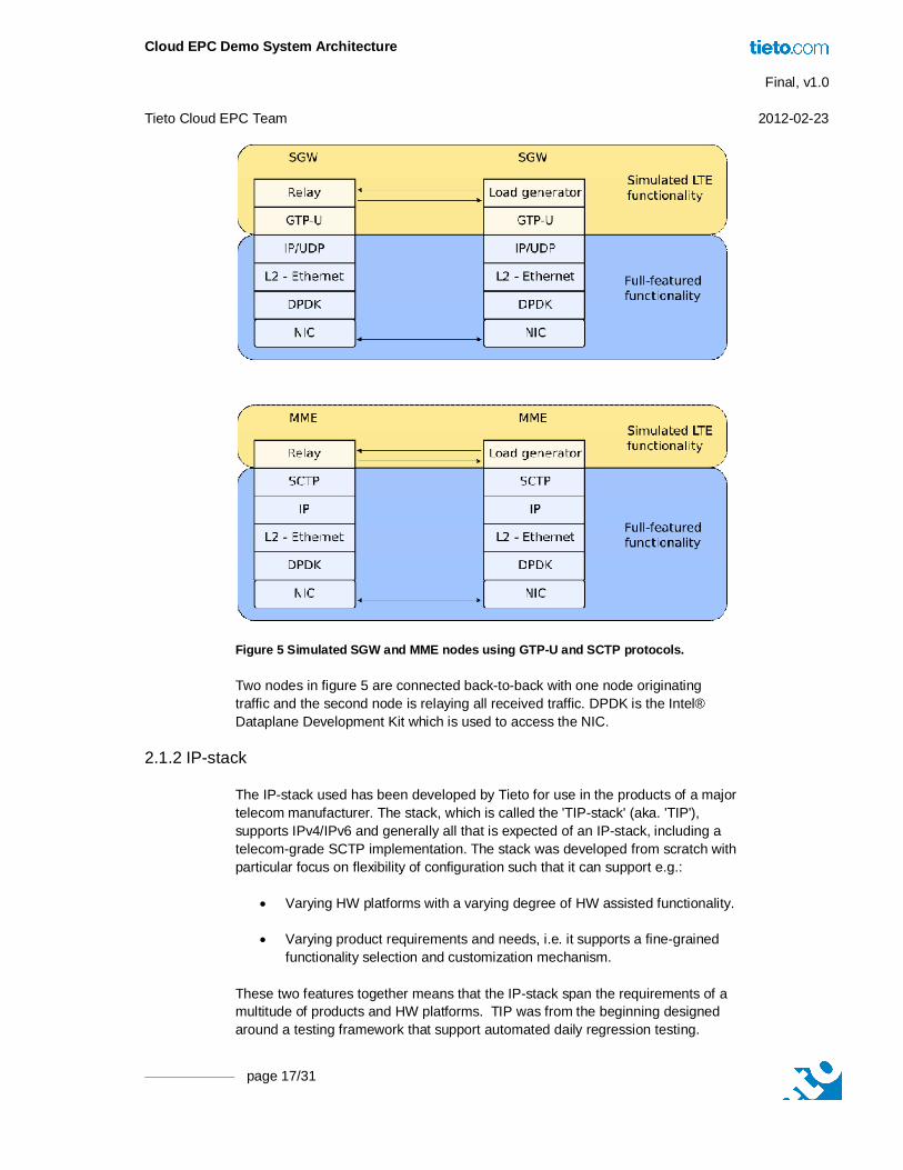
Figure 5 illustrates the components of the SGW and MME systems.
Cloud EPC Demo System Architecture Final, v1.0 Tieto Cloud EPC Team 2012-02-23
page 17/31
Figure 5 Simulated SGW and MME nodes using GTP-U and SCTP protocols.
Two nodes in figure 5 are connected back-to-back with one node originating traffic and the second node is relaying all received traffic. DPDK is the Intel® Dataplane Development Kit which is used to access the NIC.
2.1.2 IP-stack
The IP-stack used has been developed by Tieto for use in the products of a major telecom manufacturer. The stack, which is called the 'TIP-stack' (aka. 'TIP'), supports IPv4/IPv6 and generally all that is expected of an IP-stack, including a telecom-grade SCTP implementation. The stack was developed from scratch with particular focus on flexibility of configuration such that it can support e.g.:
Varying HW platforms with a varying degree of HW assisted functionality.
Varying product requirements and needs, i.e. it supports a fine-grained functionality selection and customization mechanism.
These two features together means that the IP-stack span the requirements of a multitude of products and HW platforms. TIP was from the beginning designed around a testing framework that support automated daily regression testing.
Cloud EPC Demo System Architecture Final, v1.0 Tieto Cloud EPC Team 2012-02-23
page 18/31
2.1.2.1 TIP Packet Scheduler
A key component of TIP is the scheduler. The scheduler operates on data packets and events and schedules these on various parts of the stack. Scheduled objects can be assigned priorities to support simple QoS mechanisms and objects can be specified with an ordering relative to other objects which is important for proper operation of certain functions of the stack. The scheduler is also the main interface to external events and e.g. asynchronous crypto offload events will enter the IP-stack through the scheduler and its event priority scheme.
2.1.2.2 TIP Fastpath
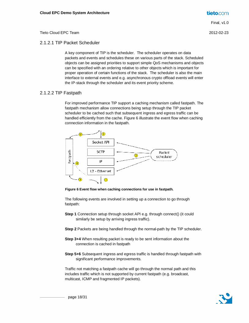
For improved performance TIP support a caching mechanism called fastpath. The fastpath mechanism allow connections being setup through the TIP packet scheduler to be cached such that subsequent ingress and egress traffic can be handled efficiently from the cache. Figure 6 illustrate the event flow when caching connection information in the fastpath.
Figure 6 Event flow when caching connections for use in fastpath.
The following events are involved in setting up a connection to go through fastpath:
Step 1 Connection setup through socket API e.g. through connect() (it could similarly be setup by arriving ingress traffic).
Step 2 Packets are being handled through the normal-path by the TIP scheduler.
Step 3+4 When resulting packet is ready to be sent information about the connection is cached in fastpath
Step 5+6 Subsequent ingress and egress traffic is handled through fastpath with significant performance improvements.
Traffic not matching a fastpath cache will go through the normal path and this includes traffic which is not supported by current fastpath (e.g. broadcast, multicast, ICMP and fragmented IP packets).
Cloud EPC Demo System Architecture Final, v1.0 Tieto Cloud EPC Team 2012-02-23
Intel is a trademark of Intel Corporation in the U.S. and/or other countries.
The current fastpath support SCTP, TCP, connected and unconnected UDP, rawIP and IPsec. Since the fastpath design is basically a cache, it has been used to offload protocol functionality to dedicated HW (e.g. IPsec) i.e. programming the SW fastpath could also program dedicated HW (e.g. offload an IPsec SPI).
2.2 Usermode Architecture
The typical communication pattern for IP over Ethernet traffic consist of a high frequency of small packets. Typical packet sizes range from less than 100 bytes up to the maximum Ethernet packet size of about 1500 bytes. The high data-rate of contemporary network technologies (e.g. 10G and 40G) results in a high frequency of packets in the NIC/IP-stack interface. Signaling protocols like SCTP bundle multiple signalling units into a single IP-datagram and since typical signalling units are 100 to 200 bytes in size it is common to have about 10 signalling units per IP-packet. Thus, in case of SCTP, the frequency of traffic between the IP-stack and the application handling signalling traffic may be up to 10 times higher than the already high frequency of traffic in the NIC/IP-stack interface.
Any extraneous overhead in the interfaces between NIC/IP-stack and IP-stack/application will have a detrimental effect on overall capacity. In a typical kernel-based IP-stack, such overhead results from:
Per IP-datagram interrupts and context switches from NIC ingress traffic. Mitigated by techniques such as interrupt coalescing.
Context-switching in the kernel/application API - typical socket API – for both ingress and egress traffic. In case of GTP-U through a socket API the frequency of context switching will match the frequency of arriving IP-datagrams and in case of SCTP the frequency may be up to 10 times higher.
In addition to these overheads, a traditional IP-stack often results in an unpredictable number of IP-datagrams handled per timeslice, i.e. it is difficult to control cache footprint and ensure cache locality by keeping datagram burst-sizes within a certain limit.
The user-mode architecture eliminates interrupts and context switches by combining IP-stack and application into the same context and by polling for ingress traffic (e.g. infinite coalescing). The term userspace refers to the fact that such a solution is often implemented in userspace outside kernelspace, although this is just a practical fact rather than a requirement of the architecture.
The current implementation is running in Linux userspace (i.e. no 'bare-metal' approach). Real-time scheduling is enabled for the IP-stack process such that Linux intervention is minimised. This is particularly important with high traffic rates if occasional packet losses are to be minimised.
Cloud EPC Demo System Architecture Final, v1.0 Tieto Cloud EPC Team 2012-02-23
Intel is a trademark of Intel Corporation in the U.S. and/or other countries.
2.2.1 Poll-mode NIC and Main Loop
The user-mode architecture in itself does not dictate any specific implementation or event handling mechanisms inside the IP-stack. However, the number of interrupts needed to handle high volumes of traffic means that interrupt coalescing is not feasible and that traffic should be read from the NIC in a polled fashion. This means that the IP-stack main-loop uses the following principle:
while (1) { get_packet_from_nic() ip_stack_process_packet() }
Since it is more efficient to retrieve and process packets in batches, the current implementation actually retrieves and processes 32 Ethernet packets at a time, i.e. the main-loop really looks like:
while (1) { ip_stack_process_burst(N=32) }
2.2.2 Internal Socket API
The application is integrated in the main-loop, i.e. the main loop with a single application looks like:
while (1) { ip_stack_process_burst(N=32) application_poll_for_events() }
The application interfaces to the IP-stack using a subset of the traditional socket API. Since the application is part of the main-loop it cannot be allowed to block, i.e. only the non-blocking subset of the socket API is supported. The Berkeley socket API (with extensions) may not be the most efficient API, but it allows portability of applications between different IP-stack environments and it is well-known and well-documented. In the current implementation the application use epoll_wait() to poll for events, i.e. the less efficient select() or poll() is not used. The application may also handle other types of events in a polled fashion (like timers).
2.2.3 Scheduling Between IP-stack and Application
Each time around in the main-loop, the IP-stack will retrieve up to 32 Ethernet packets and process them as needed. This most likely results in data being queued in socket receive queues for the application to process. In case of GTP-U it will be up to 32 messages and in case of SCTP and a typical signaling MSU size of 100-200 bytes about 300 MSUs. Since processing 32 GTP-U packets is much faster than 32 SCTP packets with up to 300 bundled MSUs there is a certain inherent imbalanced here. However, since the IP-stack cannot know the
Cloud EPC Demo System Architecture Final, v1.0 Tieto Cloud EPC Team 2012-02-23
Intel is a trademark of Intel Corporation in the U.S. and/or other countries.
traffic type on beforehand the value 32 is a compromise between ameliorating the cost of retrieving the burst and cache locality.
2.3 Multicore Scalability
The IP-stack supports distribution on multiple cores and does not require synchronization between cores. This allows for good scalability when many cores are used. It is often very desirable to have all cores together represent a single logical IP-stack even when the IP-stack functionality is distributed on multiple cores (aka. IP-stack slices). This means that all IP-stack slices can share e.g. a single IP address and from outside the system responds as a single unified IP-stack.
Ingress traffic is distributed on individual cores based on predefined settings and in the EPC demo SCTP port ranges and GTP-U endpoint ID ranges are being used. When initiating connections the IP-stack supports segmented ephemeral port ranges (UDP, TCP and SCTP) and SCTP VTAG ranges. This is however, not used on the traffic generator (which initiates connections) instead each IP-stack on the load generator has a unique IP address.
Note that load balancing using parameters from the GTP-U and SCTP headers mean that fragmented IP datagrams are not supported.
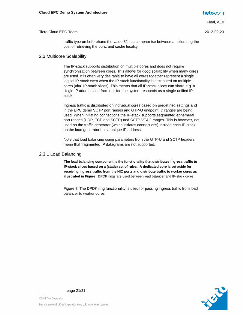
2.3.1 Load Balancing The load balancing component is the functionality that distributes ingress traffic to IP-stack slices based on a (static) set of rules. A dedicated core is set aside for receiving ingress traffic from the NIC ports and distribute traffic to worker cores as illustrated in Figure DPDK rings are used between load balancer and IP-stack cores.
Figure 7. The DPDK ring functionality is used for passing ingress traffic from load balancer to worker cores.
Cloud EPC Demo System Architecture Final, v1.0 Tieto Cloud EPC Team 2012-02-23
page 22/31
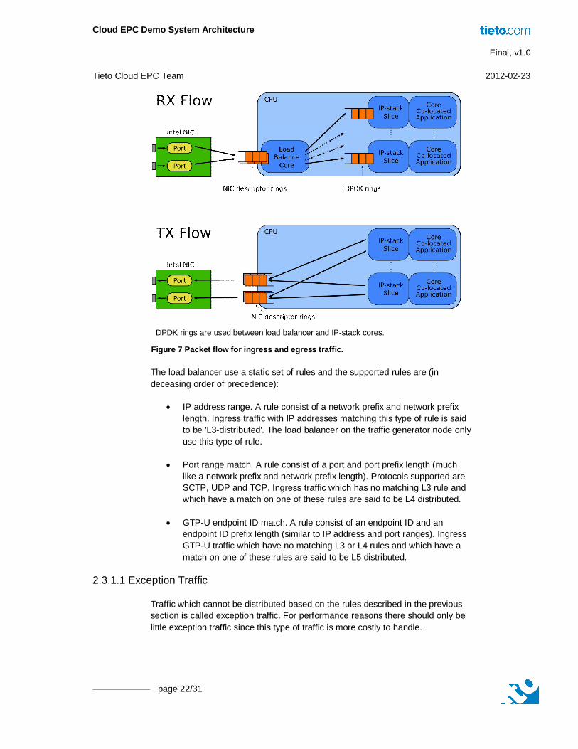
DPDK rings are used between load balancer and IP-stack cores.
Figure 7 Packet flow for ingress and egress traffic.
The load balancer use a static set of rules and the supported rules are (in deceasing order of precedence):
IP address range. A rule consist of a network prefix and network prefix length. Ingress traffic with IP addresses matching this type of rule is said to be 'L3-distributed'. The load balancer on the traffic generator node only use this type of rule.
Port range match. A rule consist of a port and port prefix length (much like a network prefix and network prefix length). Protocols supported are SCTP, UDP and TCP. Ingress traffic which has no matching L3 rule and which have a match on one of these rules are said to be L4 distributed.
GTP-U endpoint ID match. A rule consist of an endpoint ID and an endpoint ID prefix length (similar to IP address and port ranges). Ingress GTP-U traffic which have no matching L3 or L4 rules and which have a match on one of these rules are said to be L5 distributed.
2.3.1.1 Exception Traffic
Traffic which cannot be distributed based on the rules described in the previous section is called exception traffic. For performance reasons there should only be little exception traffic since this type of traffic is more costly to handle.
Cloud EPC Demo System Architecture Final, v1.0 Tieto Cloud EPC Team 2012-02-23
Intel is a trademark of Intel Corporation in the U.S. and/or other countries.
Unicast ARP traffic is forwarded to the appropriate core based on the target IP address (i.e. using L3 rules). Promiscuous broadcast ARP may also be forwarded using an L3 rule. Other broadcast ARP messages are sent to all cores.
ICMP traffic resulting from errors on L4 (SCTP) often contain part of the L4 header such that a proper L4 distribution can be performed on ICMP traffic. ICMP echo requests (ping) will be handled by the exception core if the destination IP addresses is the IP address shared by all cores (and where traffic normally is L4 distributed). If the destination IP address is one that is unique to a given core, the appropriate core will handle the request.
Ingress traffic with IP version, SCTP port or GTP-U endpoint ID falling outside the rules of the load distributor is passed to a core that is configured as the exception traffic handling core.
The first fragment of a fragmented IP packet with the shared IP address as destination will be properly distributed using L4 rules, however, the following fragments will be passed to the core handling exception traffic. This deficiency in the load balancer has not been addresses in the current project.
2.3.2 Assignment of Functionality to Cores
The load balancer utilise a single HyperThread. Since all ingress traffic needs to go through the load balancer it is considered a possible congestion point. To avoid any disturbance of this core, the associated neighbour HyperThread is unused (except on the load generator where this core is used for handling an occasional traffic rate reconfiguration). The layout of functionality on cores and HyperThreads is illustrated in Figure 8.
Cloud EPC Demo System Architecture Final, v1.0 Tieto Cloud EPC Team 2012-02-23
page 24/31
Both load generator, simulated EPC node and laptop used for controlling the demo is illustrated. The 10G network is only used for carrying SCTP and GTP-U traffic whereas the 1G network is used for controlling and monitoring the demo.
Figure 8 Functionality as mapped to cores and HyperThreads.
Cloud EPC Demo System Architecture Final, v1.0 Tieto Cloud EPC Team 2012-02-23
Intel is a trademark of Intel Corporation in the U.S. and/or other countries.
2.3.3 Power Management
The IP-stack on the simulated MME/SGW node is designed to work efficiently using only little power when only serving light loads. This is done through a combination of CPU idling using speculative sleeps and frequency hints to the HW-based frequency governor. Both CPU-load throttling and frequency hinting works individually for each core/HT.
2.3.4 CPU-load Throttling
The algorithm that implements speculative sleeps needed to throttle CPU-load is invoked whenever there is nothing for the core/HT to do, i.e. whenever rte_eth_rx_burst() returns zero packets for the load distributor and whenever rte_ring_count() return zero for one of the IP-stack cores. When 5 consecutive polls has yielded zero packets, a counter begins incrementing for each successive zero poll. When this counter is less than 100, the counter value is used as a microsecond sleep value through nanosleep(). A maximum sleep interval of 100us is used while the counter value is less than 1000. A 100us sleep interval results in the core being in C1 state. When the counter value reaches 1000, the sleep interval is changed to 500us, which results in a core/HT entering the C3 state (assuming the neighbour HT also is idle enough).
Whenever traffic is received the counter value is reset to zero.
2.3.5 Frequency Management
Linux cpufreq governor is set to ‘usermode’ which means that hints are given from userspace (the TIP-stack and load balancer) to the HW-based frequency manager. Details of the HW-based frequency manager is not known, but userspace management is based on the following assumptions:
All cores/HyperThreads use the same frequency.
The HW-based frequency manager use only the frequency steps indicated from userspace, i.e. for gradual management it is important that several different values are indicated in the different frequency settings for each HyperThread.
Only the values from significantly active cores/HyperThreads are used, i.e. a static setup with a different frequency for each core/HyperThread is not sufficient.
The actual algorithm of the HW-based frequency manager is most likely complex, but the frequency hinting done from the IP-stack needed to take the above issues in to account.
The algorithm used by the IP-stack increase the frequency based on the length of the ring between load balancer and IP-stack. On every poll for new packets the length of the ring is evaluated and the algorithm used for frequency hinting is as follows:
Cloud EPC Demo System Architecture Final, v1.0 Tieto Cloud EPC Team 2012-02-23
page 26/31
If the length of the ring exceeds 3k (out of a maximum ring size of 4k) the maximum frequency is hinted.
If the length of the ring exceeds 2k a 'trend' counter is incremented by 100.
If the length of the ring exceeds 512 the 'trend' counter is incremented by 1.
When the 'trend' counter reached 10000 the frequency hint is changed to the next higher frequency.
When the length of the ring is less than 32 the 'trend' counter is reset to zero.
If the sleeping time used for CPU throttling indicate that we are sleeping more than 22% of our time, the frequency is decreased one step. This evaluation is performed every 100ms.
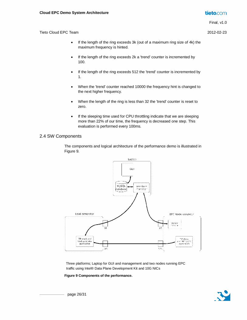
2.4 SW Components
The components and logical architecture of the performance demo is illustrated in Figure 9.
Three platforms; Laptop for GUI and management and two nodes running EPC traffic using Intel® Data Plane Development Kit and 10G NICs
Figure 9 Components of the performance.
Cloud EPC Demo System Architecture Final, v1.0 Tieto Cloud EPC Team 2012-02-23
Intel is a trademark of Intel Corporation in the U.S. and/or other countries.
The components are:
GUI A Linux Qt-based GUI application allowing users to start/stop the demo and change traffic parameters and core functionality (change between MME and SGW functionality). Values measured on the simulated EPC node is displayed in the GUI.
MySQL database Traffic settings and measured values are stored in an MySQL database. The database is the primary interface for the GUI to the rest of the system.
Interface manager This component interfaces between the database and the modules running on the load-carrying EPC systems. Traffic settings are read from the database and configured in the load generator and values are measured on the simulated EPC node and written to the database.
Sensor module Module that measures CPU load, average frequency and C-state residency for each core.
MME/SGW application and TIP-stack This is the simulated EPC node and it implements the SCTP and GTP-U protocols. The MME/SGW application is very simple and all received traffic is echoed back to the load generator.
Load generator and TIP-stack This component initiates traffic towards the simulated EPC node. This component is in principle identical to the simulated EPC node since it implements the same protocols but in addition it also performs shaping of the traffic sent towards the simulated EPC node since one traffic parameter is the traffic rate (e.g. packets/s). Traffic throughput measurements and other traffic related statistics are based on measurements from this node, Throughput measurements shown in the GUI is traffic received by this node, i.e. traffic sent from this node to the simulated EPC node and echoed back again.
2.5 IPsec Support
Traditionally base stations has been placed at operator facilities that are physically secured. In LTE however, base stations are increasingly being placed in less secure environments, and IPsec is employed to ensure confidentially and integrity for signalling and user plane traffic.
In the context of EPC, IPsec will be used to secure the backhaul links between the eNodeB nodes and the SGW/MME nodes where both GTP-U and SCTP are carried through IPsec tunnels. As illustrated in Figure 10, adjacent eNodeB nodes may communicate with each other through an IPsec tunnel (the LTE X2 interface) and each eNodeB will communicate with at least one set of MME/SGW nodes through IPsec tunnel(s) (the LTE S1 interface).
Cloud EPC Demo System Architecture Final, v1.0 Tieto Cloud EPC Team 2012-02-23
page 28/31
Figure 10 Two possible uses of IPsec tunnels.
In figure 10, Usage of IPsec tunnels between between adjacent eNodeB's and core network nodes MME and SGW are shown as:
a. direct connection from eNodeB to core network nodes
b. connection through a separate security gateway. In this case the IPsec tunnels are potentially terminated at a different node than SCTP and GTP.
Since IPsec is essential for securing the backhaul network, IPsec performance demonstrations are thus very relevant when considering the EPC IP-stack functionality.
The current EPC performance demonstration project did not include IPsec encryption of traffic, however, this section provides a proposal for how IPsec encrypted traffic could be demonstrated together with HW assist of IPsec encryption/decryption.
2.5.1 Offload Engines
There are three possible ways to implement HW assisted IPsec decryption:
NIC based The Intel® 82599 NIC supports offload of 1024 RX and 1024 TX IPsec security associations. The AES-128-CBC crypto algorithm standardised by LTE however it is not supported by the 82599 NIC. This
Cloud EPC Demo System Architecture Final, v1.0 Tieto Cloud EPC Team 2012-02-23
Intel is a trademark of Intel Corporation in the U.S. and/or other countries.
makes it unsuitable for LTE IPsec offload. The 82599 HW only support AES-128-GCM encryption.
Intel AES-NI instruction-set based Many recent Intel CPUs support the AES extended instruction set which improves the speed of AES encryption/decryption. In a multicore CPU, each core will be able to use these instructions and parallel IPsec encryption/decryption by each core is possible. Since LTE also may use the 3DES algorithm this instruction set will not be able to support all types of IPsec flows.
Cave Creek accelerator based A Crystal Forest platform contain one or more Cave Creek devices and each of these contain a number of accelerators with dedicated crypto engines. These engines may be used for asynchronous look-aside offload of IPsec encryption/decryption. The number of crypto-engines may be less than the number of CPU cores and thus fully parallel operation may not be possible. Note that details on Cave Creek has not been available.
2.5.2 Load Distribution
Prior to decryption of ingress traffic, load distribution on parameters covered by IPsec encryption is obviously not possible. Load distribution of individual ingress IPsec flows is however possible using the security parameter index (SPI) which is an 32-bit un-encrypted integer stored in the IPsec headers and which uniquely identify each SA and thus each IPsec flow.
Surveys indicate that IPsec deployments in LTE most likely will use only a few IPsec flows [2] and the IPsec encryption/decryption may thus become a bottleneck because it may not be sufficient to use load distribution solely on IPsec SPI due to the thick IPsec tunnels.
Distributing a single IPsec flow to multiple IPsec decrypt engines is not trivial due to the replay protection available in IPsec and the resulting shared state. Replay protection is based on sequence numbers and a window mechanism that ensures that each packet is only received once and only packets within a small window is accepted. If the maximum IPsec decryption capacity is less than line-speed (and the system thus vulnerable to complexity DoS attacks) then ingress packets should have their sequence number validated before IPsec decryption is initiated such that duplicated packets are not unnecessarily decrypted and possible computational complexity DoS attacks are avoided.
RFC4303 suggest small window sizes in the order of 32 to 64 packets and reordering due to load balancing and parallel decryption does not work well when reordering is close to the window size1 and this may result in legitimate packets
1 This is because the right edge of the window is moved when a packet has been validated, i.e. a reordered
packet may move the right edge of the window before a legitimate packet which has been received earlier are subjected to sequence number validation. The small window suggested by RFC4303 means that IPsec is not vulnerable to very much reordering. Increasing the window size improves robustness to reordering but also increases vulnerability to attacks.
Cloud EPC Demo System Architecture Final, v1.0 Tieto Cloud EPC Team 2012-02-23
page 30/31
being dropped even though they are within the window as seen on the network. Reordering on egress is similarly troublesome because it creates the same problem.
L4 protocols like TCP and SCTP use packet ordering to infer packet loss and invoke fast retransmission and congestion avoidance upon reordering. Typically packets are allowed to be reordered by a few positions but further reordering will have a significant impact on overall capacity.
The actual IPsec encryption/decryption of individual packets can be done in parallel. However, due to the reordering problem it needs to be followed by proper reordering unless the HW assist functionality in itself guarantees very little reordering2.
The IPsec replay protection window algorithm could be segmented such that different engines handles different parts of the sequence number space. This would reduce the reordering problem (because different windows will be used and they will basically move independently) and significantly limit the shared state between two encryption/decryption engines working on a single IPsec flow.
An example of this could be two decrypt engines with one handling the odd sequence numbers and the other handling the even sequence numbers or any similar segmentation that ensures reasonable load distribution on decrypt engines and allows de-coupled IPsec sequence number validation3. Parallel IPsec decryption is illustrated in Figure 11.
Figure 11 IPsec decrypt of a single tunnel using two-step load balancing.
2 An implementation with low reordering could be a SW entity that has a single ingress queue and which
schedules decrypt requests on HW decrypt engines. The HW should have principally identical per-packet decrypt time and/or no ingress request queue that can cause reordering due to small differences in decrypt times. Worst case reordering here should be a single packet.
3 Each sequence number segment cannot be fully decoupled from the others, some level of synchronisation is needed when updating the right edge of the window.
Cloud EPC Demo System Architecture Final, v1.0 Tieto Cloud EPC Team 2012-02-23
Intel is a trademark of Intel Corporation in the U.S. and/or other countries.
The two-step load balancing in figure 11 steps are:
a. Ingress traffic decryption is performed in parallel using the IPsec SPI for distribution and window validation is performed in parallel (with some synchronisation between cores).
b. An example where a single core perform the initial window validation and secondly offload the actual decryption on a number of HW engines. When decryption is finished, packets are reordered and passed on in the pipeline for L4/L5 load balancing. This example do not need synchronisation of window sequence numbers but will be limited by the capacity of a single core to do IPsec SA lookups, offload to HW engines and reordering. Alternatively reordering and L4/L5 LB could be placed on a second core and the practicality of this depends on the possibilities of the Intel® QuickAssist API (in particular if it is possible to drive decrypt engines from two cores simultaneously.
The ratio of IPsec decrypt engines (or encrypt in case of egress traffic) and IP-stack slices depends on the capacity of the IPsec engines, the traffic type, headroom reserved for applications above the IP-stack etc. These factors are currently not known. The IPsec encryption/decryption cannot be made fully parallel due to the window validation synchronisation between decrypt engines and the post reordering needed and as per Amdahls law it is difficult to predict without prototyping how much capacity that can be provided if thick IPsec tunnels are being used. It is however believed that the synchronisation and reordering will be light-weight such that some scaling is possible.