Clouds and the Earth's Radiant Energy System (CERES) Data Management System BiDirectional Scans (BDS) Collection Document Release 3 Version 4 Primary Authors Denise L. Cooper, Phillip C. Hess Science Systems Applications, Inc. (SSAI) One Enterprise Parkway, Suite 200 Hampton, Virginia 23666 Jonathan L. Gleason NASA Langley Research Center Climate Science Branch Science Directorate Building 1250 12 Langley Boulevard Hampton, VA 23681-2199 Kory J. Priestley NASA Langley Research Center Climate Science Branch Science Directorate Building 1250 12 Langley Boulevard Hampton, VA 23681-2199 May 2013
Transcript
Clouds and the Earth's Radiant Energy System(CERES)
Data Management System
BiDirectional Scans (BDS) Collection Document
Release 3Version 4
Primary Authors
Denise L. Cooper, Phillip C. Hess
Science Systems Applications, Inc. (SSAI)One Enterprise Parkway, Suite 200
Hampton, Virginia 23666
Jonathan L. Gleason
NASA Langley Research CenterClimate Science Branch
Science DirectorateBuilding 1250
12 Langley BoulevardHampton, VA 23681-2199
Kory J. Priestley
NASA Langley Research CenterClimate Science Branch
Science DirectorateBuilding 1250
12 Langley BoulevardHampton, VA 23681-2199
May 2013
BDS Collection Guide R3V4 5/17/2013
Document Revision Record
The Document Revision Record contains information pertaining to approved document changes. The table lists the date the Software Configuration Change Request (SCCR) was approved, the Release and Version Number, the SCCR number, a short description of the revision, and the revised sections. The document authors are listed on the cover. The Head of the CERES Data Management Team approves or disapproves the requested changes based on recommendations of the Configuration Control Board.
Document Revision Record
SCCRApproval
Date
Release/VersionNumber
SCCRNumber Description of Revision Section(s)
Affected
01/99 R3V1 xxxx TRMM Launch Version including HDF organization. All
04/00 R3V2 xxxx Minor updates- parameter units, Terra information. Supports all instrument launches.
All
xxxx The CERES Top Level Data Flow Diagram was modified (5/29/03).
1.3
R3V3 xxxx Updated latest production data products. All
This document was converted from FrameMaker to Word. (04/16/2009)
All
The CERES Top Level Data Flow Diagram was modified. (04/16/2009)
Fig. 1-1
R3V4 xxxx Updated for Aqua and S-NPP elements and additional Sun and Moon related angles. (05/17/2013)
All
ii
BDS Collection Guide R3V4 5/17/2013
PrefaceThe Clouds and the Earth’s Radiant Energy System (CERES) Data Management System supports the data processing needs of the CERES Science Team research to increase understanding of the Earth’s climate and radiant environment. The CERES Data Management Team works with the CERES Science Team to develop the software necessary to implement the science algorithms. This software, being developed to operate at the Langley Atmospheric Science Data Center (ASDC), produces an extensive set of science data products.
The Data Management System consists of 12 subsystems; each subsystem represents one or more stand-alone executable programs. Each subsystem executes when all of its required input data sets are available and produces one or more archival science products.
This Collection Guide is intended to give an overview of the science product along with definitions of each of the parameters included within the product. The document has been reviewed by the CERES Working Group teams responsible for producing the product and by the Working Group Teams who use the product.
Acknowledgement is given to Joanne H. Saunders of Science Systems and Applications, Inc. (SSAI) for her outstanding support in the preparation of this document.
Table B-21. FM 1 (Terra) Memory Patch Loads......................................................................B-57
Table B-22. FM 2 (Terra) Memory Patch Loads......................................................................B-58
Table B-23. FM 3 (Aqua) Memory Patch Loads......................................................................B-58
Table B-24. FM 4 (Aqua) Memory Patch Loads......................................................................B-59
Table B-24a. FM 5 (S-NPP) Memory Patch Loads..................................................................B-59
Table B-25. Heater Control Algorithm Default Coefficient Values.........................................B-60
xiii
BDS Collection Guide R3V4 5/17/2013
Clouds and the Earth's Radiant Energy System (CERES)BiDirectional Scans (BDS) Collection Document
Summary
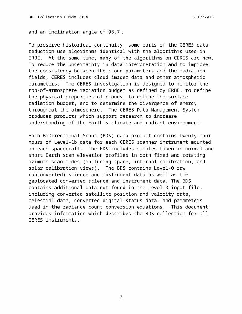
The Clouds and the Earth’s Radiant Energy System (CERES) is a key component of the Earth Observing System (EOS) program. The CERES instrument provides radiometric measurements of the Earth's atmosphere from three broadband channels: a shortwave channel (0.3 - 5 m), a total channel (0.3 - 200 m), and an infrared window channel (8 - 12 m). The CERES instruments are improved models of the Earth Radiation Budget Experiment (ERBE) scanner instruments, which operated from 1984 through 1990 on the National Aeronautics and Space Administration’s (NASA) Earth Radiation Budget Satellite (ERBS) and on the National Oceanic and Atmospheric Administration’s (NOAA) operational weather satellites NOAA-9 and NOAA-10. The strategy of flying instruments on Sun-synchronous, polar orbiting satellites, such as NOAA-9 and NOAA-10, simultaneously with instruments on satellites that have precessing orbits in lower inclinations, such as ERBS, was successfully developed in ERBE to reduce time sampling errors. CERES continues that strategy by flying instruments on the polar orbiting EOS platforms (Terra and Aqua) and NOAA’s Joint Polar Satellite System (JPSS) Suomi-NPOESS Prepatory Platform (S-NPP) simultaneously with an instrument on the Tropical Rainfall Measuring Mission (TRMM) spacecraft, which has an orbital inclination of 35. The TRMM and S-NPP satellites each carry one CERES instrument while the EOS satellites each carry two CERES instruments, one operating in a nominal fixed azimuth plane scanning mode (FAPS) for continuous Earth sampling and the other operating in a nominal rotating azimuth plane scan mode (RAPS) for improved angular sampling. The Terra and Aqua satellites orbit at a 705 km altitude with a 98.2 inclination. The Terra satellite nominally descends across the equator at 10:30 A.M. local. The Aqua satellite nominally ascends across the equator at 1:30 P.M. local. The S-NPP satellite nominally ascends across the equator at 1:30 P.M. at an altitude of 824 km and an inclination angle of 98.7.
To preserve historical continuity, some parts of the CERES data reduction use algorithms identical with the algorithms used in ERBE. At the same time, many of the algorithms on CERES are new. To reduce the uncertainty in data interpretation and to improve the consistency between the cloud parameters and the radiation fields, CERES includes cloud imager data and other atmospheric parameters. The CERES investigation is designed to monitor the top-of-atmosphere radiation budget as defined by ERBE, to define the physical properties of clouds, to define the surface radiation budget, and to determine the divergence of energy throughout the atmosphere. The CERES Data Management System produces products which support research to increase understanding of the Earth’s climate and radiant environment.
Each BiDirectional Scans (BDS) data product contains twenty-four hours of Level-1b data for each CERES scanner instrument mounted on each spacecraft. The BDS includes samples taken in normal and short Earth scan elevation profiles in both fixed and rotating azimuth scan modes (including space, internal calibration, and solar calibration views). The BDS contains Level-0 raw (unconverted) science and instrument data as well as the geolocated converted science and instrument data. The BDS contains additional data not found in the Level-0 input file, including converted satellite position and velocity data, celestial data, converted digital status data, and
1
BDS Collection Guide R3V4 5/17/2013
parameters used in the radiance count conversion equations. This document provides information which describes the BDS collection for all CERES instruments.
2
BDS Collection Guide R3V4 5/17/2013
1.0 Collection Overview
1.1 Collection IdentificationThe BDS Collection is made up of seven distinct data products. Their Product-ID and complete file names according to the CERES file naming convention are shown in Table 1-1.
where:CER Investigation designation for CERES,BDS Product-ID for the primary science data product (external distribution),BDSS Product-ID for the Solar calibration data product,BDSD Product-ID for the Diagnostic science data product,BDSF Product-ID for the Fixed pattern diagnostic data product,BDSG Product-ID for the Gimbal diagnostic data product,BDSM Product-ID for the Memory dump diagnostic data product,BDSP Product-ID for the Processor diagnostic data product,BDSI Product-ID of subsetted Internal Calibration data product,Sampling-Strategy Platform and instrument (e.g., TRMM-PFM, Terra-FM1, Aqua-FM3,
NPP-FM5),Production-Strategy Edition or campaign reference (e.g., At-launch, Edition1, Edition2),**XXXXXX Configuration Code (CC) for file and software version management,YYYY 4-digit calendar year integer,MM 2-digit calendar month integer, andDD 2-digit calendar day integer defining the data acquisition date.
** NOTE: The Slow Mode and Drift Corrected Counts SDSs are only available on Edition1 BDS products with a configuration code of 027025 or greater, Edition2 BDS products with a configuration code of 028028 or greater, and all Edition3 BDS products.
3
BDS Collection Guide R3V4 5/17/2013
1.2 Collection IntroductionThe BDS is a suite of distinct data products containing up to 24 hours of data from a single instrument and can consist of up to seven distinct products. The product available for external distribution is the BDS, the primary science product. The other products are used by the Instrument Working Group for investigating anomalies or instrument performance.
1.3 Objective/PurposeThe overall science objectives of the CERES investigation are
1. For climate change research, provide a continuation of the ERBE record of radiative fluxes at the top of the atmosphere (TOA) that are analyzed using the same techniques used with existing ERBE data.
2. Double the accuracy of estimates of radiative fluxes at the TOA and the Earth’s surface from existing ERBE data.
3. Provide the first long-term global estimates of the radiative fluxes within the Earth’s atmosphere.
4. Provide cloud property estimates which are consistent with the radiative fluxes from surface to TOA.
The CERES Data Management System (DMS) is a software management and processing system which processes CERES instrument measurements and associated engineering data to produce archival science and other data products. The DMS is executed at the LaRC ASDC, which is also responsible for distributing the data products. A high-level view of the CERES DMS is illustrated by the CERES Top Level Data Flow Diagram shown in Figure 1-1.
4
Grid TOAand Surface
Fluxes:Clouds
9
ERBE-likeAveraging toMonthly TOA
Fluxes3
Grid GEONarrowbandRadiances,
Clouds11
GEO:GeostationaryNarrowbandRadiances
TimeInterpolate,ComputeFluxes
7
Grid Radiative
Fluxes andClouds
6
MOA:Meteorological,
Ozone, andAerosol Data
ES-8:ERBE-like
InstantaneousTOA Estimates
ERBE-likeInversion to
InstantaneousTOA Fluxes
2
RegridHumidity
andTemperature
Fields12
BDS:BiDirectional
Scans
SRBAVG:Monthly
TOA/Surface Averages
SYNI:Intermediate
SynopticRadiative
Fluxes and Clouds
ComputeMonthly and
Regional TOAand SurfaceAverages
10
DetermineCloud
Properties, TOA
and Surface Fluxes
4
Geolocateand Calibrate
EarthRadiances
1
SSF: SingleScanner Footprint
TOA/Surface Fluxes and
Clouds
CRS: Clouds
and RadiativeSwath
VIRS CID:MODIS CID:
CloudImager Data
SURFMAP:Surface
Map
INSTR:InstrumentProduction Data Set
EID6:ERBE-like Regional
Data
AVG:Monthly RegionalRadiative Fluxes
and CloudsZAVG:
Monthly Zonal and Global Radiative
Fluxes and Clouds
ComputeRegional,Zonal and
GlobalAverages
8
GGEO:Gridded GEONarrowband
Radiances, Clouds
FSW: Monthly Gridded
Radiative Fluxes and
Clouds
IES: InstrumentEarth Scans
CRH:Clear
ReflectanceHistory
GAP:Gridded Analysis Product
OPD:OzoneProfileData
MWH:MicrowaveHumidity
APD:Aerosol
Data
SFC: MonthlyGridded
TOA/SurfaceFluxes and
Clouds
ES-9:ERBE-likeMonthly Regional Averages
ES-4:ERBE-likeMonthly
Geographical Averages
ComputeSurface andAtmospheric
RadiativeFluxes
5
SYNSynopticRadiative
Fluxes and Clouds
ISCCP-D2like-Day/Nit:Monthly
Gridded Cloud Averages
ISCCP-D2like-GEO:
Monthly Cloud Averages
Modified Date: October 2008
BDS Collection Guide R3V4 5/17/2013
Figure 1-1. CERES Top Level Data Flow Diagram
5
BDS Collection Guide R3V4 5/17/2013
Circles in the diagram represent algorithm processes called subsystems, which are a logical collection of algorithms that together convert input products into output products. Boxes represent archival products or data stores which are designated as nonarchival or temporary data products. Boxes or data stores with arrows entering a circle are input sources for the subsystem, while boxes or data stores with arrows exiting the circles are output products.
1.4 Summary of ParametersThe BDS parameters are divided into science, instrument, Level- 0, and metadata groupings only for discussion purposes in this document. The parameters within each grouping are listed in alphabetical order in the following sections. The parameter definitions are given in Section 4.3.2. Each parameter is mapped into the seven distinct BDS data products as shown in Table 1-2, Table 1-3, Table 1-4, and Table 1-5.
1.4.1 ScienceTable 1-2 alphabetically lists the BDS science data, which are distributed to the science community and become the basis for higher-level science products. Information in the Link and Parameter Name columns are hyperlinked to the parameter definition found in Section 4.3.2.1 Science Parameter Descriptions. The Link column identifier, SCI-n, refers to the science parameter grouping. The Structure Link column identifiers are links to a description of the Hierachical Data Format (HDF) structure and organization.
Table 1-2. Science Parameters
Link Parameter Name StructureLink B
DS
BD
SS
BD
SD
BD
SF
BD
SG
BD
SM
BD
SP
BD
SI
SCI-1 Ancillary QA Flags Set 1 (Radiance Housekeeping) Sec. 5.2.2 X X X X X X
SCI-2 Ancillary QA Flags Set 2 (Spaceclamp Algorithm) Sec. 5.2.2 X X X X X X
SCI-3 CERES Relative Azimuth at Surface Sec. 5.2.2 X X X X X X X
SCI-4 CERES Relative Azimuth at TOA - Geocentric Sec. 5.2.2 X X X X X X X
SCI-5 CERES Solar Zenith at Surface Sec. 5.2.2 X X X X X X X
SCI-6 CERES Solar Zenith at TOA - Geocentric Sec. 5.2.2 X X X X X X X
SCI-7 CERES SW Filtered Radiance, Upwards Sec. 5.2.2 X X X X
SCI-8 CERES TOT Filtered Radiance, Upwards Sec. 5.2.2 X X X X
SCI-9 CERES Viewing Zenith at Surface Sec. 5.2.2 X X X X X X X
SCI-10 CERES Viewing Zenith at TOA - Geocentric Sec. 5.2.2 X X X X X X X
SCI-11 CERES WN Filtered Radiance, Upwards Sec. 5.2.2 X X X X
SCI-12 Clock Angle of CERES FOV at Satellite wrt Inertial Velocity Sec. 5.2.2 X X X X X X X
SCI-13 Colatitude of CERES FOV at Surface Sec. 5.2.2 X X X X X X X
SCI-14 Colatitude of CERES FOV at TOA Sec. 5.2.2 X X X X X X X
SCI-15 Colatitude of Subsatellite Point at Surface at record end Sec. 5.2.3.6 X X X X X X X X
SCI-16 Colatitude of Subsatellite Point at Surface at record start Sec. 5.2.3.6 X X X X X X X X
SCI-17 Colatitude of Subsolar Point at Surface Sec. 5.2.3.6 X X X X X X X X
6
BDS Collection Guide R3V4 5/17/2013
Table 1-2. Science Parameters
Link Parameter Name StructureLink B
DS
BD
SS
BD
SD
BD
SF
BD
SG
BD
SM
BD
SP
BD
SI
SCI-17a
Colatitude of Sublunar Point at Surface Sec. 5.2.3.6 X X X X X X X X
SCI-18 Cone Angle of CERES FOV at Satellite Sec. 5.2.2 X X X X X X X
SCI-19 Count Conversion SW Sample Offsets Sec. 5.2.2 X X X X
SCI-20 Count Conversion TOT Sample Offsets Sec. 5.2.2 X X X X
SCI-21 Count Conversion WN Sample Offsets Sec. 5.2.2 X X X X
SCI-22 Drift Corrected SW Counts Sec. 5.2.2 X X X X
SCI-23 Drift Corrected TOT Counts Sec. 5.2.2 X X X X
SCI-24 Drift Corrected WN Counts Sec. 5.2.2 X X X X
SCI-25 Earth-Sun Distance Sec. 5.2.3.6 X X X X X X X X
SCI-25a
Earth-Moon Distance Sec. 5.2.3.6 X X X X X X X X
SCI-26 Julian Date and Time Sec. 5.2.2 X X X X X X X X
SCI-27 Longitude of CERES FOV at Surface Sec. 5.2.2 X X X X X X X
SCI-28 Longitude of CERES FOV at TOA Sec. 5.2.2 X X X X X X X
SCI-29 Longitude of Subsatellite Point at Surface at record end Sec. 5.2.3.6 X X X X X X X X
SCI-30 Longitude of Subsatellite Point at Surface at record start Sec. 5.2.3.6 X X X X X X X X
SCI-31 Longitude of Subsolar Point at Surface Sec. 5.2.3.6 X X X X X X X X
SCI-31a
Longitude of Sublunar Point at Surface Sec. 5.2.3.6 X X X X X X X X
SCI-31b
Lunar Azimuth Angles Sec. 5.2.2 X X X X
SCI-31c
Lunar Elevation Angles Sec. 5.2.2 X X X X
SCI-31d
Lunar Beta Angle at record start Sec. 5.2.3.6 X X X X X X X X
SCI-31e
Lunar Eta Angle at record start Sec. 5.2.3.6 X X X X X X X X
SCI-32 Primary Scan Level QA Flags Sec. 5.2.2 X X X X X X X
SCI-33 Radiance and Mode Flags Sec. 5.2.2 X X X X X X X
SCI-34 Rate of Change of Clock Angle Sec. 5.2.2 X X X X X X X
SCI-35 Rate of Change of Cone Angle Sec. 5.2.2 X X X X X X X
SCI-36 Sample Aligned Analog Data Sec. 5.2.2 X X X X X X X X
SCI-37 Satellite Position at record end Sec. 5.2.3.6 X X X X X X X X
SCI-38 Satellite Position at record start Sec. 5.2.3.6 X X X X X X X X
SCI-39 Satellite Velocity at record end Sec. 5.2.3.6 X X X X X X X X
SCI-40 Satellite Velocity at record start Sec. 5.2.3.6 X X X X X X X X
7
BDS Collection Guide R3V4 5/17/2013
Table 1-2. Science Parameters
Link Parameter Name StructureLink B
DS
BD
SS
BD
SD
BD
SF
BD
SG
BD
SM
BD
SP
BD
SI
SCI-41 Secondary Sample Level QA Flags Sec. 5.2.2 X X X X X X X
SCI-42 Secondary Scan Level QA Flags Sec. 5.2.2 X X X X X X X
SCI-42a
Solar Beta Angle at Record Start Sec. 5.2.3.6 X X X X X X X
SCI-42b
Solar Eta Angle at Record Start Sec. 5.2.3.6 X X X X X X X
SCI-42c
Solar Azimuth Angles Sec. 5.2.2 X X X X
SCI-42d
Solar Elevation Angles Sec. 5.2.2 X X X X
SCI-42e
Solar Calibration MAM FOV Azimuth Angles Sec. 5.2.2 X
SCI-42f Solar Calibration MAM FOV Elevation Angles Sec. 5.2.2 X
SCI-43 SW Channel Spurious Slow Mode Constants Sec. 5.2.3.4 X X X X
SCI-44 TOT Channel Spurious Slow Mode Constants Sec. 5.2.3.4 X X X X
SCI-45 WN Channel Spurious Slow Mode Constants Sec. 5.2.3.4 X X X X
SCI-46 SW Channel Gain Constants Sec. 5.2.3.4 X X X X
SCI-47 TOT Channel Gain Constants Sec. 5.2.3.4 X X X X
SCI-48 WN Channel Gain Constants Sec. 5.2.3.4 X X X X
SCI-49 SW Radiance Edit Limits Sec. 5.2.3.4 X X X X
SCI-50 TOT Radiance Edit Limits Sec. 5.2.3.4 X X X X
SCI-51 WN Radiance Edit Limits Sec. 5.2.3.4 X X X X
SCI-52 SW Spaceclamp Values Sec. 5.2.2 X X X X
SCI-53 TOT Spaceclamp Values Sec. 5.2.2 X X X X
SCI-53 WN Spaceclamp Values Sec. 5.2.2 X X X X
SCI-55 SW Slow Mode and Drift Corrected Counts ** Sec. 5.2.2 X X X X
SCI-56 TOT Slow Mode and Drift Corrected Counts ** Sec. 5.2.2 X X X X
SCI-57 WN Slow Mode and Drift Corrected Counts ** Sec. 5.2.2 X X X X**These SDSs are available on Aqua and Terra Edition1 BDSs beginning with CC-Code 027025, Aqua and Terra Edition2 BDSs beginning with CC-Code 028028, and all Edition3 BDSs.
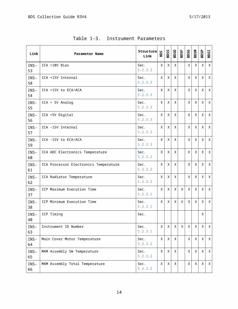
1.4.2 InstrumentTable 1-3 alphabetically lists the BDS converted instrument engineering data, which are primarily intended for quality evaluation of the science parameters. While many of these parameters have both a raw and converted value, only one definition is given in Section 4.3.2.2 Instrument Parameter Descriptions and is accessible by the Link and Parameter Name hyperlink columns. The Link column identifier, INS-n, refers to the instrument data grouping. The
8
BDS Collection Guide R3V4 5/17/2013
Structure Link column identifiers are links to a HDF organization description. The corresponding raw values (See Table 1-4) are in different data structures than the converted values.
Table 1-3. Instrument Parameters
Link Parameter Name StructureLink B
DS
BD
SS
BD
SD
BD
SF
BD
SG
BD
SM
BD
SP
BD
SI
INS-1 ACA Electronics Temperature Sec. 5.2.3.2 X X X X X X X
INS-2 ACA Torque Output Sec. 5.2.3.3 X X X X X X X
INS-3 Azimuth Defined Asynchronous Scan Rate Sec. 5.2.3.1 X X X X X X X X
INS-4 Azimuth Defined Crosstrack Position Sec. 5.2.3.1 X X X X X X X X
INS-5 Azimuth Defined Fixed Cage Position Sec. 5.2.3.1 X X X X X X X X
INS-6 Azimuth Defined Fixed Position A Sec. 5.2.3.1 X X X X X X X X
INS-7 Azimuth Defined Fixed Position B Sec. 5.2.3.1 X X X X X X X X
INS-8 Azimuth Defined Fixed Position Spare 1 Sec. 5.2.3.1 X X X X X X X X
INS-9 Azimuth Defined Fixed Position Spare 2 Sec. 5.2.3.1 X X X X X X X X
INS-10 Azimuth Defined Fixed Position Spare 3 Sec. 5.2.3.1 X X X X X X X X
INS-11 Azimuth Defined Fixed Solar Calibration Position Sec. 5.2.3.1 X X X X X X X X
INS-12 Azimuth Defined Normal Slew Rate Sec. 5.2.3.1 X X X X X X X X
INS-13 Azimuth Defined Synchronous Scan Rate Sec. 5.2.3.1 X X X X X X X X
INS-14 Azimuth Error Sec. 5.2.2 X
INS-15 Azimuth Lower Bearing Temperature Sec. 5.2.3.2 X X X X X X X
INS-16 Azimuth Offset Correction Sec. 5.2.3.1 X X X X X X X X
INS-17 Azimuth Position Error Sec. 5.2.3.1 X X X X X X X X
INS-18 Azimuth Upper Bearing Temperature Sec. 5.2.3.2 X X X X X X X
INS-19 Converted Azimuth Angles Sec. 5.2.2 X X X X X X X
INS-20 Converted Elevation Angles Sec. 5.2.2 X X X X X X X
INS-21 DAA +10V Reference Sec. 5.2.3.3 X X X X X X X
INS-22 DAA +12V Sec. 5.2.3.3 X X X X X X X
INS-23 DAA +130V Sec. 5.2.3.3 X X X X X X X
INS-24 DAA +15V Sec. 5.2.3.3 X X X X X X X
INS-25 DAA +5V Sec. 5.2.3.3 X X X X X X X
INS-26 DAA -10V Reference Sec. 5.2.3.3 X X X X X X X
INS-27 DAA -12V Sec. 5.2.3.3 X X X X X X X
INS-28 DAA -130V Sec. 5.2.3.3 X X X X X X X
INS-29 DAA -15V Sec. 5.2.3.3 X X X X X X X
INS-30 DAA ADC Electronics Temperature Sec. 5.2.3.2 X X X X X X X
INS-31 DAA Ground Reference 1 Sec. 5.2.3.3 X X X X X X X
INS-32 DAA Ground Reference 2 Sec. 5.2.3.3 X X X X X X X
9
BDS Collection Guide R3V4 5/17/2013
Table 1-3. Instrument Parameters
Link Parameter Name StructureLink B
DS
BD
SS
BD
SD
BD
SF
BD
SG
BD
SM
BD
SP
BD
SI
INS-33 DAA Processor Electronics Temperature Sec. 5.2.3.2 X X X X X X X
INS-34 DAA Radiator Temperature Sec. 5.2.3.2 X X X X X X X
INS-35 DAP Maximum Execution Time Sec. 5.2.3.1 X X X X X X X X
INS-36 DAP Minimum Execution Time Sec. 5.2.3.1 X X X X X X X X
INS-39 DAP Timing Sec. 5.2.2 X
INS-41 Detector +120V Bias Sec. 5.2.3.3 X X X X X X X
INS-42 Detector -120V Bias Sec. 5.2.3.3 X X X X X X X
INS-43 ECA Electronics Temperature Sec. 5.2.3.2 X X X X X X X
INS-44 ECA Radiator Temperature Sec. 5.2.3.2 X X X X X X X
INS-45 ECA Torque Output Sec. 5.2.3.3 X X X X X X X
INS-47 Elevation Bearing Temperature-CW Sec. 5.2.3.2 X X X X X X X
INS-48 Elevation Bearing Temperature-Motor Sec. 5.2.3.2 X X X X X X X
INS-49 Elevation Error Sec. 5.2.2 X
INS-50 Elevation Offset Correction Sec. 5.2.3.1 X X X X X X X X
INS-51 Elevation Spindle Temperature-CW Sec. 5.2.3.2 X X X X X X X
INS-52 Elevation Spindle Temperature-Motor Sec. 5.2.3.2 X X X X X X X
INS-53 ICA +10V Bias Sec. 5.2.3.3 X X X X X X X
INS-58 ICA +15V Internal Sec. 5.2.3.3 X X X X X X X
INS-54 ICA +15V to ECA/ACA Sec. 5.2.3.3 X X X X X X X
INS-55 ICA + 5V Analog Sec. 5.2.3.3 X X X X X X X
INS-56 ICA +5V Digital Sec. 5.2.3.3 X X X X X X X
INS-57 ICA -15V Internal Sec. 5.2.3.3 X X X X X X X
INS-59 ICA -15V to ECA/ACA Sec. 5.2.3.3 X X X X X X X
INS-60 ICA ADC Electronics Temperature Sec. 5.2.3.2 X X X X X X X
INS-61 ICA Processor Electronics Temperature Sec. 5.2.3.2 X X X X X X X
INS-62 ICA Radiator Temperature Sec. 5.2.3.2 X X X X X X X
INS-37 ICP Maximum Execution Time Sec. 5.2.3.1 X X X X X X X X
INS-38 ICP Minimum Execution Time Sec. 5.2.3.1 X X X X X X X X
INS-40 ICP Timing Sec. 5.2.2 X
INS-63 Instrument ID Number Sec. 5.2.3.1 X X X X X X X X
INS-64 Main Cover Motor Temperature Sec. 5.2.3.2 X X X X X X X
INS-65 MAM Assembly SW Temperature Sec. 5.2.3.2 X X X X X X X
INS-66 MAM Assembly Total Temperature Sec. 5.2.3.2 X X X X X X X
INS-67 MAM Total Baffle Temperature 1 Sec. 5.2.3.2 X X X X X X X
INS-68 MAM Total Baffle Temperature 2 Sec. 5.2.3.2 X X X X X X X
10
BDS Collection Guide R3V4 5/17/2013
Table 1-3. Instrument Parameters
Link Parameter Name StructureLink B
DS
BD
SS
BD
SD
BD
SF
BD
SG
BD
SM
BD
SP
BD
SI
INS-69 Packet Counter - Absolute Sec. 5.2.3.1 X X X X X X X X
INS-70 Packet Counter - Relative Sec. 5.2.3.1 X X X X X X X X
INS-71 Packet Data Indicator Sec. 5.2.3.1 X X X X X X X X
INS-72 Packet Data Version Sec. 5.2.3.1 X X X X X X X X
INS-73 Packet Timecode Indicator Sec. 5.2.3.1 X X X X X X X X
INS-74 PCA Electronics Temperature Sec. 5.2.3.2 X X X X X X X
INS-75 PCA Radiator Temperature Sec. 5.2.3.2 X X X X X X X
INS-76 Pedestal Temperature 1-Brake Housing Sec. 5.2.3.2 X X X X X X X
INS-77 Pedestal Temperature 2-Isolator Sec. 5.2.3.2 X X X X X X X
INS-78 Science Packet Quick Look Status Flag Sec. 5.2.3.1 X X X X X X X X
INS-79 Sensor Electronics Temperature Sec. 5.2.3.2 X X X X X X X
INS-80 Sensor Module Temperature Sec. 5.2.3.2 X X X X X X X
INS-81 SW Detector Control Temperature Sec. 5.2.3.2 X X X X X X X
INS-84 SW Detector Monitor Temperature Sec. 5.2.3.2 X X X X X X X
INS-87 SWICS Lamp Current Sec. 5.2.3.3 X X X X X X X
INS-88 SWICS Photodiode Temperature Sec. 5.2.3.2 X X X X X X X
INS-89 TOT Blackbody Temperature Sec. 5.2.3.2 X X X X X X X
INS-83 WN Detector Control Temperature Sec. 5.2.3.2 X X X X X X X
INS-85 TOT Detector Monitor Temperature Sec. 5.2.3.2 X X X X X X X
INS-90 WN Blackbody Temperature Sec. 5.2.3.2 X X X X X X X
INS-83 WN Detector Control Temperature Sec. 5.2.3.2 X X X X X X X
INS-86 WN Detector Monitor Temperature Sec. 5.2.3.2 X X X X X X X
1.4.3 Level-0Table 1-4 alphabetically lists the Level-0 raw instrument science and engineering data, which are the fundamental digital measurements from the CERES instrument. The Link and Parameter Name column identifiers are hyperlinked to the parameter definition found in Section 4.3.2.3 Level-0 Parameter Descriptions. The Link column identifier, LVL-n, refers to the Level-0 parameter grouping. The Structure Link column identifiers are links to a description of the HDF structure and organization.
11
BDS Collection Guide R3V4 5/17/2013
Table 1-4. Level-0 Parameters
Link Parameter Name StructureLink B
DS
BD
SS
BD
SD
BD
SF
BD
SG
BD
SM
BD
SP
BD
SI
INS-1 ACA Electronics Temperature Sec. 5.2.3.7 X X X X X X X
12
BDS Collection Guide R3V4 5/17/2013
Table 1-4. Level-0 Parameters
Link Parameter Name StructureLink B
DS
BD
SS
BD
SD
BD
SF
BD
SG
BD
SM
BD
SP
BD
SI
LVL-1 ACA Encoder Clear Track A Sec. 5.2.3.5 X X X X X X X
LVL-2 ACA Encoder Clear Track B Sec. 5.2.3.5 X X X X X X X
INS-2 ACA Torque Output Sec. 5.2.3.8 X X X X X X X
LVL-3 Azimuth Brake Position Sec. 5.2.3.5 X X X X X X X
LVL-4 Azimuth Error Counts Sec. 5.2.2 X
INS-15 Azimuth Lower Bearing Temperature Sec. 5.2.3.7 X X X X X X X
LVL-5 Azimuth Position Count Sec. 5.2.2 X X X X X X X
INS-18 Azimuth Upper Bearing Temperature Sec. 5.2.3.7 X X X X X X X
LVL-6 Blackbody Heater DAC Value Sec. 5.2.3.7 X X X X X X X
INS-21 DAA +10V Reference Sec. 5.2.3.8 X X X X X X X
INS-22 DAA +12V Sec. 5.2.3.8 X X X X X X X
INS-23 DAA +130V Sec. 5.2.3.8 X X X X X X X
INS-24 DAA +15V Sec. 5.2.3.8 X X X X X X X
INS-25 DAA +5V Sec. 5.2.3.8 X X X X X X X
INS-26 DAA -10V Reference Sec. 5.2.3.8 X X X X X X X
INS-27 DAA -12V Sec. 5.2.3.8 X X X X X X X
INS-28 DAA -130V Sec. 5.2.3.8 X X X X X X X
INS-29 DAA -15V Sec. 5.2.3.8 X X X X X X X
INS-30 DAA ADC Electronics Temperature Sec. 5.2.3.7 X X X X X X X
INS-31 DAA Ground Reference 1 Sec. 5.2.3.8 X X X X X X X
INS-32 DAA Ground Reference 2 Sec. 5.2.3.8 X X X X X X X
INS-33 DAA Processor Electronics Temperature Sec. 5.2.3.7 X X X X X X X
INS-34 DAA Radiator Temperature Sec. 5.2.3.7 X X X X X X X
LVL-7 DAP Memory Sec. 5.2.2 X
LVL-9 DAP Timing Counts Sec. 5.2.2 X
INS-41 Detector +120V Bias Sec. 5.2.3.8 X X X X X X X
INS-42 Detector -120V Bias Sec. 5.2.3.8 X X X X X X X
INS-43 ECA Electronics Temperature Sec. 5.2.3.7 X X X X X X X
INS-44 ECA Radiator Temperature Sec. 5.2.3.5 X X X X X X X
LVL-12 ECA Encoder Clear Track B Sec. 5.2.3.5 X X X X X X X
13
BDS Collection Guide R3V4 5/17/2013
Table 1-4. Level-0 Parameters
Link Parameter Name StructureLink B
DS
BD
SS
BD
SD
BD
SF
BD
SG
BD
SM
BD
SP
BD
SI
INS-44 ECA Radiator Temperature Sec. 5.2.3.7 X X X X X X X
INS-45 ECA Torque Output Sec. 5.2.3.8 X X X X X X X
INS-51 Elevation Spindle Temperature-CW Sec. 5.2.3.7 X X X X X X X
INS-52 Elevation Spindle Temperature-Motor Sec. 5.2.3.7 X X X X X X X
LVL-13 Elevation Error Counts Sec. 5.2.2 X
LVL-14 Elevation Position Count Sec. 5.2.2 X X X X X X X
INS-51 Elevation Spindle Temperature-CW Sec. 5.2.3.7 X X X X X X X
INS-52 Elevation Spindle Temperature-Motor Sec. 5.2.3.7 X X X X X X X
LVL-15 Fixed Pattern 1 Sec. 5.2.2 X
LVL-16 Fixed Pattern 2 Sec. 5.2.2 X
LVL-17 Fixed Pattern 3 Sec. 5.2.2 X
LVL-18 Fixed Pattern 4 Sec. 5.2.2 X
LVL-19 Fixed Pattern 5 Sec. 5.2.2 X
LVL-20 Fixed Pattern 6 Sec. 5.2.2 X
INS-53 ICA +10V Bias Sec. 5.2.3.8 X X X X X X X
INS-58 ICA +15V Internal Sec. 5.2.3.8 X X X X X X X
INS-54 ICA +15V to ECA/ACA Sec. 5.2.3.8 X X X X X X X
INS-55 ICA + 5V Analog Sec. 5.2.3.8 X X X X X X X
INS-56 ICA +5V Digital Sec. 5.2.3.8 X X X X X X X
INS-57 ICA -15V Internal Sec. 5.2.3.8 X X X X X X X
INS-59 ICA -15V to ECA/ACA Sec. 5.2.3.8 X X X X X X X
INS-60 ICA ADC Electronics Temperature Sec. 5.2.3.7 X X X X X X X
INS-61 ICA Processor Electronics Temperature Sec. 5.2.3.7 X X X X X X X
INS-62 ICA Radiator Temperature Sec. 5.2.3.7 X X X X X X X
LVL-8 ICP Memory Sec. 5.2.2 X
LVL-10 ICP Timing Counts Sec. 5.2.2 X
INS-64 Main Cover Motor Temperature Sec. 5.2.3.7 X X X X X X X
LVL-21 Main Cover Position 1 Sec. 5.2.3.5 X X X X X X X
LVL-22 Main Cover Position 2 Sec. 5.2.3.5 X X X X X X X
INS-65 MAM Assembly SW Temperature Sec. 5.2.3.7 X X X X X X X
14
BDS Collection Guide R3V4 5/17/2013
Table 1-4. Level-0 Parameters
Link Parameter Name StructureLink B
DS
BD
SS
BD
SD
BD
SF
BD
SG
BD
SM
BD
SP
BD
SI
INS-66 MAM Assembly Total Temperature Sec. 5.2.3.7 X X X X X X X
LVL-23 MAM Cover Position Sec. 5.2.3.5 X X X X X X X
INS-67 MAM Total Baffle Temperature 1 Sec. 5.2.3.7 X X X X X X X
INS-68 MAM Total Baffle Temperature 2 Sec. 5.2.3.7 X X X X X X X
INS-74 PCA Electronics Temperature Sec. 5.2.3.7 X X X X X X X
INS-75 PCA Radiator Temperature Sec. 5.2.3.7 X X X X X X X
INS-76 Pedestal Temperature 1-Brake Housing Sec. 5.2.3.7 X X X X X X X
INS-77 Pedestal Temperature 2-Isolator Sec. 5.2.3.7 X X X X X X X
LVL-25 Raw Instrument Status Data Sec. 5.2.2 X X X X X X X X
INS-79 Sensor Electronics Temperature Sec. 5.2.3.7 X X X X X X X
INS-80 Sensor Module Temperature Sec. 5.2.3.7 X X X X X X X
LVL-26 Spacecraft Time Sec. 5.2.2 X
LVL-27 SPS 1 Narrow FOV Sec. 5.2.3.5 X X X X X X X
LVL-28 SPS 1 Wide FOV Sec. 5.2.3.5 X X X X X X X
LVL-29 SPS 2 Narrow FOV Sec. 5.2.3.5 X X X X X X X
LVL-30 SPS 2 Wide FOV Sec. 5.2.3.5 X X X X X X X
LVL-31 SW Channel Heater DAC Value Sec. 5.2.3.7 X X X X X X X
INS-81 SW Detector Control Temperature Sec. 5.2.3.7 X X X X X X X
INS-84 SW Detector Monitor Temperature Sec. 5.2.3.7 X X X X X X X
LVL-34 SW Detector Outputs Sec. 5.2.2 X X X X
INS-87 SWICS Lamp Current Sec. 5.2.3.8 X X X X X X X
LVL-37 SWICS Photodiode Output Sec. 5.2.3.8 X X X X X X X
INS-88 SWICS Photodiode Temperature Sec. 5.2.3.7 X X X X X X X
LVL-35 TOT Detector Outputs Sec. 5.2.2 X X X X
INS-89 TOT Blackbody Temperature Sec. 5.2.3.7 X X X X X X X
LVL-32 Total Channel Heater DAC Value Sec. 5.2.3.7 X X X X X X X
INS-82 TOT Detector Control Temperature Sec. 5.2.3.7 X X X X X X X
INS-85 TOT Detector Monitor Temperature Sec. 5.2.3.7 X X X X X X X
INS-90 WN Blackbody Temperature Sec. 5.2.3.7 X X X X X X X
LVL-33 WN Channel Heater DAC Value Sec. 5.2.3.7 X X X X X X X
15
BDS Collection Guide R3V4 5/17/2013
Table 1-4. Level-0 Parameters
Link Parameter Name StructureLink B
DS
BD
SS
BD
SD
BD
SF
BD
SG
BD
SM
BD
SP
BD
SI
INS-83 WN Detector Control Temperature Sec. 5.2.3.7 X X X X X X X
INS-86 WN Detector Monitor Temperature Sec. 5.2.3.7 X X X X X X X
LVL-36 WN Detector Outputs Sec. 5.2.2 X X X X
16
BDS Collection Guide R3V4 5/17/2013
1.4.4 MetadataThe BDS metadata is summarized in Table 1-5 and the detailed listings are in Appendix A.
Table 1-5. BDS Metadata Summary
DescriptionTable HDF Name
BD
SB
DSS
BD
SDB
DSF
BD
SGB
DSM
BD
SPB
DSI
Table A-1 CERES Baseline Header Metadata X X X X X X X XTable A-2 CERES_metadata Vdata X X X X X X X XTable A-3 BDS Product Specific Metadata X X X X X X X X
1.5 DiscussionThe Geolocate and Calibrate Earth Radiances or Instrument Subsystem (SS1.0) is the first data processing unit in the CERES Data Management System. The primary input data set is a 24-hour, Level-0 instrument data stream of chronologically-ordered data packets. Each packet contains a full 6.6 second scan cycle of measurement data from the three broadband radiometric channels. The radiance measurements are sampled and output every 0.01 second while engineering data are sampled at least once in each scan cycle. Examples of the engineering data are elevation and azimuth positions, voltage and temperature measurements, and instrument status information. SS1.0 converts the Level-0 digital count data into geolocated and calibrated spectrally filtered radiances for the three radiometric channels. The Level-0 orbit ephemeris and spacecraft attitude data along with the elevation and azimuth positions are used to compute the science measurement geolocation. SS1.0 also converts all instrument engineering and spacecraft ephemeris data into engineering units. A post-processing program extracts a subset of BDS parameters (called a Pre-ES8) for input to the ERBE-like Subsystem 2.0. Subsystem 1.0 also produces the IES product which is input to the Cloud Subsystem 4.0.
1.6 Related CollectionsSee the CERES Data Products Catalog (Reference 1) for a complete product listing.
17
BDS Collection Guide R3V4 5/17/2013
2.0 InvestigatorsDr. Norman G. Loeb, CERES Principal InvestigatorMail Stop 420Atmospheric Sciences Division Building 125021 Langley BoulevardNASA Langley Research CenterHampton, Virginia 23681-2199Telephone: (757) 864-5688FAX: (757) 864-7996E-mail: [email protected]
2.1 Title of InvestigationGeolocate and Calibrate Earth Radiances (Subsystem 1.0)
2.2 Contact InformationDr. Kory Priestley, Instrument Working Group ChairMail Stop 420Atmospheric Sciences Division Building 125021 Langley BoulevardNASA Langley Research CenterHampton, Virginia 23681-2199Telephone: (757) 864-8147FAX: (757) 864-7996E-mail: [email protected]
18
BDS Collection Guide R3V4 5/17/2013
3.0 OriginationThe CERES data originate from CERES instruments on-board the TRM, the EOS Earth-orbiting spacecrafts, Terra and Aqua, or the JPSS S-NPP spacecraft. Table 3-6 lists the CERES instruments and their host satellites.
Table 3-6. CERES Instruments
Satellite CERES InstrumentsTRMM ProtoFlight Model [PFM]Terra Flight Model 1 [FM 1]
(operationally designated "CEF")Flight Model 2 [FM 2](operationally designated "CEA")
Aqua Flight Model 3 [FM 3](operationally designated "CEA")
Flight Model 4 [FM 4](operationally designated "CEF")
S-NPP Flight Model 5 [FM 5](operationall designated “CE”)
The CERES instrument contains three scanning thermistor bolometer radiometers that measure the radiation in the near-visible through far-infrared spectral region. The shortwave detector measures Earth-reflected and Earth-emitted solar radiation and the window detector measures Earth-emitted longwave radiation in the water vapor window. The total detector measures total Earth-reflected and Earth-emitted radiance. The detectors are coaligned and mounted on a spindle that rotates about the instrument elevation axis. The resolution of the CERES radiometers is usually referenced to the optical FOV (See Note-3).
The CERES instrument has an operational scanning cycle of 6.6 seconds and various scan elevation profiles. Radiometric measurements are sampled from the detectors every 0.01 seconds in all scanning profiles. The instrument makes Earth-viewing science measurements while the detectors rotate in the vertical (elevation scan) plane, and while the instrument horizontal (azimuth scan) plane is either fixed or rotating. The instrument has built-in calibration sources for performing in-flight calibrations, and can also be calibrated by measuring solar radiances reflected by a solar diffuser plate into the instrument field of view. See the In-flight Measurement Analysis document, DRL 64, provided by the CERES instrument builder TRW (Reference 2), and the CERES Algorithm Theoretical Basis Document (ATBD) for Subsystem 1.0 (Reference 3).
19
BDS Collection Guide R3V4 5/17/2013
4.0 Data Description
4.1 Spatial Characteristics
4.1.1 Spatial CoverageThe BDS collection is a global data set whose spatial coverage depends on the satellite orbit as shown in Table 4-7. The BDS contains all daily orbital swaths of CERES footprint data.
Table 4-7. BDS Spatial Coverage
Spacecraft:Instrument(s)
MinimumLatitude
(deg)
MaximumLatitude
(deg)
MinimumLongitude
(deg)
MaximumLongitude
(deg)
SpacecraftAltitude
(km)TRMM: PFM -52 52 -180 180 350Terra: FM 1 & FM 2 -90 90 -180 180 705Aqua: FM 3 & FM 4 -90 90 -180 180 705S-NPP: FM 5 -90 90 -180 180 824
4.1.2 Spatial ResolutionEach BDS record represents 660 CERES measurements. The spatial scale of each measurement or footprint varies with the viewing zenith. The resolution of the CERES radiometers is usually referenced to the optical FOV (See Term-6).
4.2 Temporal Characteristics
4.2.1 Temporal CoverageThe BDS temporal coverage begins after the spacecraft is launched, the scan covers are opened, and the early in-orbit calibration check-out is completed (See Table 4-8).
Table 4-8. BDS Temporal Coverage
Spacecraft Instrument Launch Date Start Date End DateTRMM PFM 11/27/1997 12/27/1997 8/31/1998*Terra FM 1 & FM 2 12/18/1999 2/26/2002 presentAqua FM 3 & FM 4 5/4/2002 6/26/2002 present
S-NPP FM 5 10/28/2011 1/27/2012 present
* The PFM instrument operated intermittently since 1 September, 1998 due to a power converter anomaly in the data acquisition electronics. PFM resumed crosstrack operations on 26 February, 2000. Radiometric coverage continued until 5 April, 2000 when electronic noise caused too much corruption for meaningful science results. A complete loss of radiance data occurred on 14 June, 2000 due to thermal shutdown of the analog-to-digital converter electronics believed to be induced by the failed power converter.
20
BDS Collection Guide R3V4 5/17/2013
4.2.2 Temporal ResolutionThe CERES instrument is expected to be operational throughout the TRMM and EOS mission lifetimes. Since BDS products are produced whenever the CERES instruments are operational, a continuous global data collection is expected. Each BDS measurement within a record represents a radiometric measurement taken every 0.01 seconds, and each record covers 6.6 seconds.
4.3 Data Characteristics
4.3.1 Parameter/VariableThe complete alphabetical listings of BDS parameters are shown in Section 1.0 in Table 1-2, Table 1-3, and Table 1-4 and correspond to the science, instrument, and Level-0 groupings, respectively. The parameter descriptions beginning in the next section are also organized by science (SCI), instrument (INS), and Level-0 (LVL) groupings where SCI, INS, and LVL are acronyms denoting the particular data grouping. Listed for each definition are the (units), [range], and a link to the section describing the parameter structure as it is written to the output product. The ranges are considered nominal values unless specified otherwise. For example, if a parameter has an associated QA flag, a non-nominal range may have been used for quality testing.
4.3.2 Variable Description/Definition
4.3.2.1 Science Parameter DescriptionsThe CERES science parameters are computed using the geodetic coordinate system. However, several parameters are computed in the geocentric coordinate system, and will specifically include the term "geocentric" in the parameter name. The geocentric parameters are used by the ERBE-like Subsystems since ERBE products are archived in the geocentric coordinate system. An alphabetical listing of the science parameters is shown in Table 1-2.
SCI-1 Ancillary QA Flags Set 1 (Radiance Housekeeping)This parameter is a 32-bit word that contains various quality assurance flags about scan and measurement level data that are used in the radiance conversion algorithm. The status word bit ordering is shown in Figure 4-2, where zero is the least significant bit. Note: beginning with CC version 016011 BDS products, this parameter was discontinued. Individual flags were reassigned to the Primary_Scan_Level_QA_Flags, Secondary_Scan_Level_QA_Flags, and Secondary_Sample_Level_QA_Flags parameters. (none) [N/A] Section 5.2.2 BDS SDS Summary
21
031
32-Bit Word
Spare
WN Radiance Edit
WN Heatsink Temp EditSW Heatsink Temp Edit TOT Heatsink Temp Edit WN DAC Voltage Edit SW DAC Voltage Edit
Main Cover StatusMAM Cover StatusElevation Profile ID
BDS Collection Guide R3V4 5/17/2013
Figure 4-2. Ancillary QA Flags Set 1 (Radiance Housekeeping)
The individual flags are identified in Table 4-9 with links to their descriptions.
Table 4-9. Ancillary QA Flags Set 1 (Radiance Housekeeping)
Item Bits Flag Parameter Name Item Bits Flag Parameter Name0 Spares. Set to zero QAPSC-9 16 .. 17 TOT Heatsink Temperature Edit Check:
QAPSC-4 1 .. 5 Elevation Profile ID: QAPSC-9 18 .. 19 SW Heatsink Temperature Edit Check:QAPSC-5 6 MAM Cover Status: QAPSC-9 20 .. 21 WN Heatsink Temperature Edit Check:QAPSC-6 7 Main Cover Status: QASSA-2 22 .. 24 TOT Radiance Edit Check:QAPSC-7 8 .. 9 Bias Voltage Edit Check: QASSA-2 25 .. 27 SW Radiance Edit Check:QAPSC-8 10 .. 11 TOT DAC Voltage Edit Check: QASSA-2 28 .. 30 WN Radiance Edit Check:QAPSC-8 12 .. 13 SW DAC Voltage Edit Check: 31 N/A; Set to zero
QAPSC-8 14 .. 15 WN DAC Voltage Edit Check:
SCI-2 Ancillary QA Flags Set 2 (Spaceclamp Algorithm)This 32-bit word contains information about measurement level data that are used in the radiance conversion algorithm. The bit ordering of the status word is shown below in Figure 4-3. Note: beginning with CC version 016011 BDS products, this parameter was discontinued. Individual flags were reassigned to the Primary_Scan_Level_QA_Flags, Secondary_Scan_Level_QA_Flags, and Secondary_Sample_Level_QA_Flags parameters. (none) [N/A] Section 5.2.2 BDS SDS Summary
Figure 4-3. Ancillary QA Flags Set 2 (Instrument Algorithm)
The individual flags are identified in Table 4-10 with links to their descriptions.
Table 4-10. Ancillary QA Flags Set 2 (Instrument Algorithm)
Item Bits Flag Parameter Item Bits Flag Parameter0 .. 2 Spares. Set to zero QASSC-1 17 .. 20 SW SpaceClamp Status:
QASSA-1 3 .. 5 TOT 2nd Time Constant Vk Status: QASSC-1 21 .. 24 WN SpaceClamp Status:QASSA-1 6 .. 8 SW 2nd Time Constant Vk Status: QAPSC-2 25 .. 26 TOT DAC Status:QASSA-1 9 .. 11 WN 2nd Time Constant Vk Status: QAPSC-2 27 .. 28 SW DAC Status:
QA-10 12 .. 12 Measurement Used in Spaceclamp: QAPSC-2 29 .. 30 WN DAC Status:QASSC-1 13 .. 16 TOT SpaceClamp Status: 31 N/A; Set to zero
SCI-3 CERES Relative Azimuth at SurfaceThis parameter is the geodetic azimuth angle (See Figure 4-4) at the Earth point (See Term-5) of the satellite relative to the solar plane. (deg) [0 .. 360] Section 5.2.2 BDS SDS Summary
23
SunZenith (geodetic or geocentric)
Satellite
Plane
normalto Zenith
ForwardScatter
SolarPlane
Earth Point orTOA Point
BDS Collection Guide R3V4 5/17/2013
Figure 4-4. Viewing Angles at Surface or TOA
The relative azimuth is measured clockwise in the plane normal to the geodetic zenith (See Term-10) so that the relative azimuth of the Sun is always 180o. The solar plane is the plane
24
BDS Collection Guide R3V4 5/17/2013
which contains the geodetic zenith vector and a vector from the Earth point to the Sun. If the Earth point is north of the geodetic subsolar point (See Term-9) on the same meridian, then an azimuth of 90o would imply the satellite is east of the Earth point.
SCI-4 CERES Relative Azimuth at TOA - GeocentricThis parameter is the geocentric azimuth angle (See Figure 4-4) at the TOA point (See Term-15) of the satellite relative to the solar plane. (deg) [0 .. 360] Section 5.2.2 BDS SDS Summary
The relative azimuth is measured clockwise in the plane normal to the geocentric zenith (See Term-8) so that the relative azimuth of the Sun is always 180o. The solar plane is the plane which contains the geocentric zenith vector and a vector from the TOA point to the Sun. If the TOA point is north of the geocentric subsolar point (See Term-7) on the same meridian, then an azimuth of 90o would imply the satellite is east of the target point.
SCI-5 CERES Solar Zenith at SurfaceThis parameter is the geodetic zenith angle (See Figure 4-4) at the Earth point (See Term-5) of the Sun. (deg) [0 .. 180] Section 5.2.2 BDS SDS Summary
The geodetic solar zenith is the angle between the geodetic zenith (See Term-10) vector and a vector from the Earth point to the Sun.
SCI-6 CERES Solar Zenith at TOA - GeocentricThis parameter is the geocentric zenith angle (See Figure 4-4) at the TOA point (See Term-15) of the Sun. (deg) [0 .. 180] Section 5.2.2 BDS SDS Summary
25
BDS Collection Guide R3V4 5/17/2013
The geocentric solar zenith is the angle between the geocentric zenith (See Term-8) vector and a vector from the TOA point to the Sun.
SCI-7 CERES SW Filtered Radiance, UpwardsThe CERES SW filtered radiance is the measured, spectrally integrated radiance emerging from the TOA (See Term-14), where the spectral integration is weighted by the spectral throughput of the SW channel. It is the measurement from the SW channel after count conversion (Reference 3). (Wm-2 sr-1) [-5 .. 375] Section 5.2.2 BDS SDS Summary
The SW filtered radiance is a measure of all radiance that passes through the SW channel. The spectral weighting produced by the SW channel throughput is the product of the SW filter throughput and the TOT channel throughput (See SCI-8). The SW spectral throughput passes about 75% of the radiant power with wavelengths shorter than 5 m and cuts off sharply at about 5 m. Wavelengths longer than this wavelength contribute a very small fraction of this measurement. The SW filtered radiance value is defined as either “good” or “bad” by the Radiance and Mode Flags (See SCI-33). If the value is “bad”, for any reason, the SW filtered radiance is set to a default fill value. If the value is “good”, the measured value is retained.
SCI-8 CERES TOT Filtered Radiance, UpwardsThe CERES TOT filtered radiance is the measured, spectrally integrated radiance emerging from the TOA, where the spectral integration is weighted by the spectral throughput of the TOT channel. It is the measurement from the TOT channel after count conversion (Reference 3). (Wm-2 sr-1) [-5 .. 420] Section 5.2.2 BDS SDS Summary
The TOT filtered radiance is a measure of all radiance that passes through the TOT channel. The spectral weighting produced by the TOT channel throughput is the product of the primary mirror reflectance, the secondary mirror reflectance, and the absorptance of the detector flake. The TOT spectral throughput passes about 90% of the radiant power with wavelengths longer than 5m and about 85% of the power with shorter wavelengths. The filtered TOT radiance value is defined as either “good” or “bad” by the Radiance and Mode Flags (See SCI-33). If the value is “bad”, for any reason, the TOT filtered radiance is set to a default fill value. If the value is “good”, the measured value is retained.
SCI-9 CERES Viewing Zenith at SurfaceThis parameter is the geodetic angle (See Figure 4-4) at the Earth point (See Term-5) to the satellite. (deg) [0 .. 90] Section 5.2.2 BDS SDS Summary
The geodetic viewing zenith is the angle between the geodetic zenith (See Term-8) vector and a vector from the Earth point to the satellite.
SCI-10 CERES Viewing Zenith at TOA - GeocentricThis parameter is the geocentric angle (See Figure 4-4) at the TOA point (See Term-15) to the satellite. (deg) [0 .. 90] Section 5.2.2 BDS SDS Summary
The geocentric viewing zenith is the angle between the geocentric zenith (See Term-8) vector and a vector from the TOA point to the satellite.
26
BDS Collection Guide R3V4 5/17/2013
SCI-11 CERES WN Filtered Radiance, UpwardsThe CERES WN filtered radiance is a measured, spectrally integrated radiance emerging from the TOA, where the spectral integration is weighted by the spectral throughput of the WN channel. It has a bandpass from approximately 8 to 12 m. It is the measurement from the window channel after count conversion (Reference 3). (Wm-2 sr-1) [-2 .. 105] Section 5.2.2 BDS SDS Summary
The WN filtered radiance is a measure of all radiance that passes through the WN channel. The spectral weighting produced by the WN channel throughput is the product of the WN filter throughput and the TOT channel throughput (See SCI-8). The WN spectral throughput passes about 67% of the radiant power between 8 to 12 m. The filtered WN radiance value is defined as either “good” or “bad” by the Radiance and Mode Flags (SCI-33). If the value is “bad”, for any reason, the WN filtered radiance is set to a default fill value. If the value is “good”, the measured value is retained.
SCI-12 Clock Angle of CERES FOV at Satellite wrt Inertial VelocityThe clock angle (See Figure 4-5 and Figure 4-7) is the azimuth angle of the instrument view vector from the satellite to the Earth point (See Term-5) relative to the inertial velocity vector. (deg) [0 .. 360] Section 5.2.2 BDS SDS Summary
X
Y
Z
Earth Equator
Satellite
VelocityAngular vector
Gre
enw
ich
Me r
i di a
n
Inertial
momentum Radius to satellite
= clock
Earth pointat surface
Figure 4-5. Clock Angle
The clock angle, along with the cone angle (See Figure 4-7 and SCI-18) define the direction of the instrument view vector to the Earth point.
27
BDS Collection Guide R3V4 5/17/2013
28
BDS Collection Guide R3V4 5/17/2013
The clock angle is defined in a right-handed coordinate system centered at the satellite where z is toward the center of the Earth, x is in the direction of the inertial velocity vector, and y completes the triad. When = 270o, the Earth point is on the same side of the orbit as the orbital angular momentum vector (See Figure 4-5). When = 0o, the Earth point is directly ahead of the satellite. This is true when the spacecraft is flying in the +x axis forward orientation. For TRMM, the spacecraft will need to fly -x axis forward whenever the Solar beta angle is less than zero. Under these conditions, the sign of this clock angle will be negative.
The toolkit call (See Reference 4) PGS_CSC_SCtoORB transforms the instrument view vector in spacecraft coordinates to (x,y,z) orbital coordinates and the clock angle is defined byx /d=cos , y /d=sin , and d=√x2+ y2 .
SCI-13 Colatitude of CERES FOV at Surface This parameter is the geodetic colatitude angle d (See Figure 4-6) of the Earth point (See Term-5). (deg) [0 .. 180] Section 5.2.2 BDS SDS Summary
The geodetic colatitude is the angle between the geodetic zenith (See Term-10) at the Earth point and a vector normal to the Earth equator toward the North pole as defined in the Earth equator, Greenwich meridian system (See Term-3).
SCI-14 Colatitude of CERES FOV at TOAThis parameter is the geodetic colatitude angle c (See Figure 4-6) of the TOA point (See Term-15). (deg) [0 .. 180] Section 5.2.2 BDS SDS Summary
c
d
X
Y
Z
Geocentric Zenith
Earth Equator
GreenwichMeridian
Geodetic Zenith(North)
Figure 4-6. Geocentric and Geodetic Colatitude/Longitude
29
BDS Collection Guide R3V4 5/17/2013
The geodetic colatitude is the angle between the geodetic zenith (See Term-10) at the TOA point and a vector normal to the Earth equator toward the North pole as defined in the Earth equator, Greenwich meridian system (See Term-3).
SCI-15 Colatitude of Subsatellite Point at Surface at record endThis parameter is the geodetic colatitude angle d (See Figure 4-6) of the subsatellite point (See Term-12). The end of the record is 6.59 sec after the start of the record. (deg) [0 .. 180] Section 5.2.3.6 Satellite - Celestial Data
The geodetic colatitude is the angle between the geodetic zenith (See Term-10) to the satellite and a vector normal to the Earth equator toward the North pole as defined in the Earth equator, Greenwich meridian system (See Term-3).
SCI-16 Colatitude of Subsatellite Point at Surface at record startSee SCI-15: Colatitude of Subsatellite Point at Surface at record end.
SCI-17 Colatitude of Subsolar Point at SurfaceThis parameter is the geodetic colatitude angle d (See Figure 4-6) of the geodetic subsolar point (See Term-9) on the Earth surface (See Term-4). (deg) [0 .. 180] Section 5.2.3.6 Satellite - Celestial Data
The geodetic colatitude is the angle between the geodetic zenith (See Term-10) to the Sun and a vector normal to the Earth equator toward the North pole as defined in the Earth equator, Greenwich meridian system (See Term-3).
SCI-17a Colatitude of Sublunar Point at SurfaceThis parameter is the geodetic colatitude angle d (See Figure 4-6) of the geodetic sublunar point (See Term-9) on the Earth surface (See Term-4). (deg) [72 .. 119] Section 5.2.3.6 Satellite - Celestial Data
The geodetic colatitude is the angle between the geodetic zenith (See Term-10) to the Moon and a vector normal to the Earth equator toward the North pole as defined in the Earth equator, Greenwich meridian system (See Term-3).
SCI-18 Cone Angle of CERES FOV at SatelliteThe cone angle (See Figure 4-7) is the angle between a vector from the satellite to the center of the Earth and the instrument view vector from the satellite to the Earth point (See Term-15).(deg) [0 .. 90] Section 5.2.2 BDS SDS Summary
The cone angle, along with the clock angle, (See Figure 4-5 and SCI-12) define the direction of the instrument view vector to the Earth point.
Offset 660FAPS NormalFAPS ShortRAPS NormalRAPS Short
BDS Collection Guide R3V4 5/17/2013
Earth
satellite
point
= cone
c lo c k
Nadir
Center of Earth
Figure 4-7. Cone and Clock Angles
The toolKit call (See Reference 4) PGS_CSC_SCtoORB transforms the instrument view vector in spacecraft coordinates to (x,y,z) orbital coordinates and the cone angle is defined by z=cos α.
SCI-19 Count Conversion SW Sample Offsets
SCI-20 Count Conversion TOT Sample Offsets
SCI-21 Count Conversion WN Sample OffsetsThese three parameters contain the detector count offsets for the SW, TOT and WN detector channels, respectively. (count) [N/A] Section 5.2.2 BDS SDS Summary
Each of these offset parameters are written to the output product as a HDF Science Data Set (SDS) structure. Each structure is organized as a 4 x 660 matrix of 32-bit floating point numbers and can be depicted as 4 sets of 660 sample based offset values (See Figure 4-8). During processing, one or more sets of offsets are used in the count conversion process, depending on the elevation and azimuth modes of the instrument.
Figure 4-8. SDS format for mode dependent count offsets
SCI-22 Drift Corrected SW Counts
SCI-23 Drift Corrected TOT CountsSCI-24 Drift Corrected WN Counts
31
BDS Collection Guide R3V4 5/17/2013
These parameters contains the raw count values for each detector channel, adjusted for spaceclamp, DAC update, and scan-to-scan interpolation effects. In essence, these are the resulting counts that are derived from the spaceclamp algorithm process described in Section 6.3.3. These count values are used for evaluating radiance count conversion gain coefficients and as data input for validation analyzes (e.g. 2nd time constant effects). (count) [N/A] Section 5.2.2 BDS SDS Summary
SCI-25 Earth-Sun DistanceThe Earth-Sun distance is the distance from the Earth’s surface to the Sun and is updated at the start of every packet. The ToolKit routine PGS_CBP_Earth_CB_Vector computes the Earth-Centered Inertial (ECI) position vector to the Sun. The ToolKit routine PGS_CSC_ECItoECR transforms the ECI position vector to the Earth-Centered Rotating (ECR) or Earth equator, Greenwich meridian rectangular coordinate system (See Term-3). The Earth-Sun distance is computed from the position vector using the distance formula and then converted from meters to AU. (AU) [0.98..1.02] Section 5.2.3.6 Satellite - Celestial Data.
SCI-25a Earth-Moon DistanceThe Earth-Moon distance is the distance from the Earth’s surface to the Moon and is updated at the start of every packet. The ToolKit routine PGS_CBP_Earth_CB_Vector computes the Earth-Centered Inertial (ECI) position vector to the Moon. The ToolKit routine PGS_CSC_ECItoECR transforms the ECI position vector to the Earth-Centered Rotating (ECR) or Earth equator, Greenwich meridian rectangular coordinate system (See Term-3). The Earth-Moon distance is computed from the position vector using the distance formula and then converted from meters to AU. (AU) [0.0024..0.0027] Section 5.2.3.6 Satellite - Celestial Data.
SCI-26 Julian Date and TimeThe Julian Date (or day) and Time is the time at which the CERES radiometers recorded the measurement. The Julian day changes at Greenwich noon rather than midnight (See Term-11). The time is a fraction of a day. The ToolKit routine PGS_TD_SCtime_to_UTC converts Spacecraft time to UTC time. A second ToolKit routine, PGS_TD_UTCtoUTCjd, converts the ASCII string into two 64-bit real numbers. (day) N/A] Section 5.2.2 BDS SDS Summary
SCI-27 Longitude of CERES FOV at Surface This parameter is the longitude angle (See Figure 4-6) of the Earth point (See Term-5). (deg) [0 .. 360] Section 5.2.2 BDS SDS Summary
The longitude is the angle in the Earth equator plane from the Greenwich meridian (See Term-3) to the Earth point meridian, rotating East. The geocentric longitude and geodetic longitude are the same.
SCI-28 Longitude of CERES FOV at TOAThis parameter is the longitude angle (See Figure 4-6) of the TOA point (See Term-15). (deg) [0 .. 360] Section 5.2.2 BDS SDS Summary
32
BDS Collection Guide R3V4 5/17/2013
The longitude is the angle in the Earth equator plane from the Greenwich meridian (See Term-3) to the TOA point meridian, rotating East. The geocentric longitude and geodetic longitude are the same.
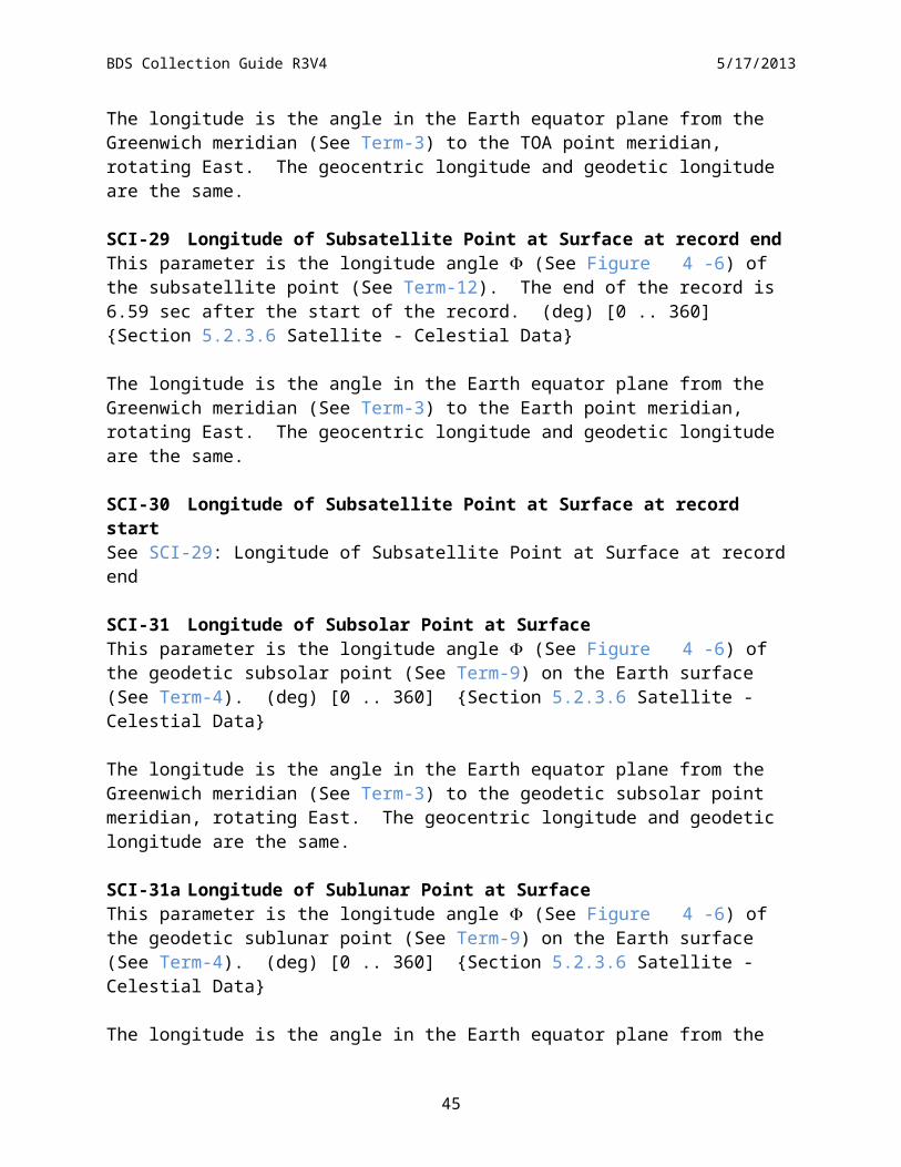
SCI-29 Longitude of Subsatellite Point at Surface at record endThis parameter is the longitude angle (See Figure 4-6) of the subsatellite point (See Term-12). The end of the record is 6.59 sec after the start of the record. (deg) [0 .. 360] Section 5.2.3.6 Satellite - Celestial Data
The longitude is the angle in the Earth equator plane from the Greenwich meridian (See Term-3) to the Earth point meridian, rotating East. The geocentric longitude and geodetic longitude are the same.
SCI-30 Longitude of Subsatellite Point at Surface at record startSee SCI-29: Longitude of Subsatellite Point at Surface at record end
SCI-31 Longitude of Subsolar Point at SurfaceThis parameter is the longitude angle (See Figure 4-6) of the geodetic subsolar point (See Term-9) on the Earth surface (See Term-4). (deg) [0 .. 360] Section 5.2.3.6 Satellite - Celestial Data
The longitude is the angle in the Earth equator plane from the Greenwich meridian (See Term-3) to the geodetic subsolar point meridian, rotating East. The geocentric longitude and geodetic longitude are the same.
SCI-31a Longitude of Sublunar Point at SurfaceThis parameter is the longitude angle (See Figure 4-6) of the geodetic sublunar point (See Term-9) on the Earth surface (See Term-4). (deg) [0 .. 360] Section 5.2.3.6 Satellite - Celestial Data
The longitude is the angle in the Earth equator plane from the Greenwich meridian (See Term-3) to the geodetic sublunar point meridian, rotating East. The geocentric longitude and geodetic longitude are the same.
SCI-31b Lunar Azimuth AngleThis angle is measured in the X-Y plane of the spacecraft between the vector along the spacecraft –Y axis and the Moon vector projected onto the spacecraft X-Y plane. The value of the azimuth angle is zero when the two vectors are coaligned and is measured positive as a clockwise rotation of spacecraft –Y axis vector. (deg) [0 .. 360] Section 5.2.2 BDS SDS Summary
SCI-31c Lunar Elevation AngleThis angle is measured between the Moon vector and the X-Y plane of the spacecraft. The value of the elevation angle is zero when the Moon vector is in the X-Y plane and is measured positive when the Moon is above the X-Y plane. (deg) [-90 .. 90] Section 5.2.2 BDS SDS Summary
33
031
32-Bit Word
Spare
WN Heatsink Temp EditSW Heatsink Temp Edit TOT Heatsink Temp Edit WN DAC Voltage Edit SW DAC Voltage Edit
TOT DAC Voltage Edit Bias Voltage Edit Main Cover StatusMAM Cover StatusElevation Profile ID
SW DAC StatusTOT DAC Status
WN DAC StatusDAA Ground Ref
TOT DC StatusSW DC StatusWN DC Status
BDS Collection Guide R3V4 5/17/2013
SCI-31d Lunar Beta Angle at Record StartThe lunar beta angle is the signed angle of the Moon vector relative to the spacecraft X-Z axis orbital plane. The signed angle is positive when the vector to the Moon is in the direction of the orbit normal. (deg) [-90 .. 90] Section 5.2.3.6 Satellite - Celestial Data
SCI-31e Lunar Eta Angle at Record StartThe solar Eta angle is the signed angle of the Lunar vector projected onto the spacecraft X-Z axis orbital plane relative to the spacecraft Z-axis. (deg) [0 .. 360] Section 5.2.3.6 Satellite - Celestial Data
SCI-32 Primary Scan Level QA FlagsThis parameter is a 32-bit word that contains various quality assurance flags about scan level data that are used in the radiance conversion algorithm. The status word bit ordering is shown in Figure 4-9, where zero is the least significant bit. Note: beginning with CC version 016011 BDS products, this parameter, along with the Secondary_Scan_Level_QA_Flags and Secondary_Sample_Level_QA_Flags parameters, replaces the Ancillary_QA_Flags_Set_1 and Ancillary_QA_Flags_Set_2 parameters. See SCI-1 and SCI-2 for individual flag descriptions. (none) [N/A] Section 5.2.2 BDS SDS Summary
Figure 4-9. Primary Scan Level QA Flags
The individual flags are identified in Table 4-11 with links to their descriptions.
34
BDS Collection Guide R3V4 5/17/2013
Table 4-11. Primary Scan Level QA Flags
Item Bits Flag Parameter Name Item Bits Flag Parameter Name0 Spares. Set to zero QAPSC-5 16 .. 16 MAM Cover Status:
QAPSC-1 1 TOT DC Status: QAPSC-6 17 .. 17 Main Cover Status:[QAPSC-1 2 SW DC Status: QAPSC-7 18 .. 19 Bias Voltage Edit Check:QAPSC-1 3 WN DC Status: QAPSC-8 20 .. 21 TOT DAC Voltage Edit Check:QAPSC-2 4 .. 5 TOT DAC Status: QAPSC-8 22 .. 23 SW DAC Voltage Edit Check:QAPSC-2 6 .. 7 SW DAC Status: QAPSC-8 24 .. 25 WN DAC Voltage Edit Check:QAPSC-2 8 .. 9 WN DAC Status: QAPSC-9 26 .. 27 TOT Heatsink Temperature Edit Check:QAPSC-3 10 .. 10 DAA Ground Reference Check: QAPSC-9 28 .. 29 SW Heatsink Temperature Edit Check:QAPSC-4 11 .. 15 Elevation Profile ID: QAPSC-9 30 .. 31 WN Heatsink Temperature Edit Check:
QAPSC-1 TOT/SW/WN DC Status (A scan level flag):This flag indicates of the sensor count measurements were single or double drift corrected. Need due to very long second time constant asymptotic settling across scan boundaries. Note, these bits are utilized in BDS products with CC versions 027205 or later.
0 = Single: The scan counts were drift corrected only once.1 = Double: The scan counts were drift corrected twice.
QAPSC-2 TOT/SW/WN DAC Status (A scan level flag):A digital-to-analog converter (DAC) is used to digitize measurements. Due to the inherent drift of the detectors, it must shift scales to maintain the proper dynamic range of the DAC. This status represents the scaling operations performed.
00 = Good: The bridge balance controller was on and in a maintenance configuration.01 = Updated: The bridge balance controller did an update (fine adjustment).10 = Reset: The bridge balance controller did a reset (coarse adjustment).11 = Off: The bridge balance controller was off.
QAPSC-3 DAA Ground Reference Check (A scan level flag):This flag identifies that the data within the current scan may be corrupted due to the occurrence of a ground power spike. This effects the reference comparison voltage in the Analog-to-Digital converts.
0 = Good: 1 = Bad:
QAPSC-4 Elevation Profile ID (A scan level flag):This flag identifies the actual elevation scan profile being performed for this scan. The values are used internally by the processing system. It is an index used by the radiance count conversion process for accessing the corresponding position offset table. ID values vary depending on the instrument and the variety of profile options created or selected by the science team.
QAPSC-5 MAM Cover Status (A scan level flag):The Mirror Attenuator Mosaic (MAM) is used for solar calibrations. It has a contamination cover which is commanded open as part of initial on-orbit check-out.
0 = Opened1 = Closed
QAPSC-6 Main Cover Status (A scan level flag):The main contamination cover shields the radiometric detectors during launch operations. It is commanded open as part of initial on-orbit checkout.
0 = Opened
35
BDS Collection Guide R3V4 5/17/2013
1 = Closed
QAPSC-7 Bias Voltage Edit Check (A scan level flag):A bias voltage is converted from counts to volts and is used to compute a scan average for the radiance count conversion equations.
00 = Passed all edit checks (See Section 6.3.7).01 = Failed a high limit edit check.10 = Failed a low limit edit check.11 = Failed a rate edit check (measurement-to-measurement).
QAPSC-8 TOT/SW/WN DAC Voltage Edit Check (A scan level flag):A digital-to-analog converter (DAC) voltage count value is used to compute a scan average for the radiance count conversion equations.
00 = Passed all edit checks (See Section 6.3.7).01 = Failed a high limit edit check.10 = Failed a low limit edit check.11 = Failed a rate edit check (measurement-to-measurement).
QAPSC-9 TOT/SW/WN Heatsink Temperature Edit Check (A scan level flag):A converted heatsink temperature is used to compute a scan average for the radiance count conversion equations.
00 = Passed all edit checks (See Section 6.3.7).01 = Failed a high limit edit check.10 = Failed a low limit edit check.11 = Failed a rate edit check (measurement-to-measurement).
SCI-33 Radiance and Mode FlagsThis parameter contains the science measurement level quality flags. It is a 32-bit word where a single bit corresponds to a particular quality assessment flag. Every measurement contained in the BDS has an associated flag. The word bit ordering is shown in Figure 4-10, where bit zero identifies the least significant bit. The individual flags are defined in Table 4-12 followed by their descriptions. Currently, this flag is also included in the IES, SSF, and CRS products. (none) [N/A] Section 5.2.2 BDS SDS Summary
Used in SW SpaceclampUsed in TOT SpaceclampUsed in WN Spaceclamp
BDS Collection Guide R3V4 5/17/2013
Figure 4-10. Radiance and Mode Flags
The individual flags are identified in Table 4-12 with links to their descriptions.
Table 4-12. Radiance and Mode Quality Flags Definition
Link Bits Flag Parameter Link Bits Flag ParameterQA-1 0 .. 1 CERES FOV Flag QA-8 19 .. 21 Offset Table IndexQA-2 2 .. 3 SW Filtered Radiance Flag QA-9 22 .. 23 3-Channel CompareQA-2 4 .. 5 WN Filtered Radiance Flag QA-10 24 Used in WN SpaceclampQA-2 6 .. 7 TOT Filtered Radiance Flag QA-10 25 Used in TOT SpaceclampQA-3 8 .. 9 Azimuth Scan Plane QA-10 26 Used in SW SpaceclampQA-4 10 .. 13 Elevation Scan Profile QA-11 27 Solar EclipseQA-5 14 Azimuth Motion Status 28 .. 30 Spares. Set to zeroQA-6 15 .. 16 Elevation Scan Rate 31 N/A; Set to zeroQA-7 17 Clock Angle RateQA-7 18 Cone Angle Rate
QA-1 CERES FOV Flag:This flag is set for each CERES science measurement and is used to identify where the CERES footprint is viewing. The footprint FOV (See Term-6) used by the geolocation calculations is based on the centroid of the detector point-spread-function, not on the optical line-of-sight. (See Reference 3 or Term-1). FOV
37
BDS Collection Guide R3V4 5/17/2013
calculations use the Earth surface model (WGS-84) and the CERES TOA model (30km above the WGS-84 model) provided by the ECS ToolKit.
00 = Full_Earth_Viewing set if- The FOV PSF centroid pierces both the Earth surface and the TOA surface, and- The footprint viewing area is determined to be completely on the Earth surface.
01 = Partial_Earth set if- The FOV PSF centroid pierces both the Earth and TOA surface, and- The FOV footprint area includes part of the Earth’s surface (i.e., straddling the Earth
limb).10 = Hit_TOA_Missed_Earth set if
- The FOV PSF centroid pierces TOA surface, but not the Earth’s surface, and- The FOV footprint area may include part of the Earth’s surface (i.e., straddling the Earth
limb).11 = Missed TOA and Earth set if
- The FOV PSF centroid for this measurement does not pierce either the Earth’s surface or the TOA surface (e.g., the FOV is looking at a cold space above the TOA). Though the centroid does not pierce the TOA surface, the FOV footprint area may partially overlap this surface.
QA-2 SW/WN/TOT Filtered Radiance Flags:These status flags are set for each CERES science measurement. Additional flags in the Ancillary QA Flags Set 1 (See SCI-1) provide specific information on the relevant instrument parameters.
00 = Good: All of the following conditions are met:- All values of instrument parameters, which are used for count conversion (bias voltage,
detector voltages, heatsink temperatures), passed edit limit and rate limit checks, and the overall state of the instrument is nominal for making radiometric measurements. The spaceclamp value has been computed, and passed edit and rate limit checks (See Section 6.3.3).
- The instrument spurious slow mode has been corrected (See Section 6.3.4)- None of the detectors were saturated at the time the measurements were taken.- Final radiance values passed edit checks (See Section 6.3.7).- There were no computational or numerical errors resulting from the count conversion
process.01 = Eclipse: This measurement is good. However, this measurement was geolocated in the
shadow of a solar eclipse event. (See Term-16)10 = Bad: Failed one or more of the above conditions. The CERES default fill value is
output instead of the actual computed radiance value (See Table 4-24).11 = Reserved - Not used.
QA-3 Azimuth Scan Plane:This flag is derived from scan level information and is used to define the azimuth gimbal scan plane for each measurement (See INS-19). Individual bit patterns are defined as follows:
00 = Crosstrack set if- This flag is set when the azimuth gimbal is in a fixed position with the elevation
scanning plane within 45 degrees of the normal to the spacecraft velocity vector. Typically, this means the gimbal is at the 180 (or 0) degree azimuth position as defined by the instrument coordinate system. This azimuth position allows the elevation scan to sweep across the ground track in a side-to-side motion. This scan plane flag is a special case of the FAPS.
01 = RAPS (Biaxial) set if- This flag is set when the azimuth gimbal is rotating between two defined azimuth end
points for the measurement. 10 = FAPS set if
- This flag is set when the azimuth gimbal is in a fixed position at any position other than crosstrack for the measurement. For example, the instrument may be in the along-track
38
BDS Collection Guide R3V4 5/17/2013
scan plane where the elevation scan plane is oriented parallel to the spacecraft velocity vector (e.g., the azimuth position = 90 or 270 degrees).
11 = Transitional set if- Defined as anything not covered above. Typically, this flag is set when the instrument is
changing between the crosstrack and biaxial modes while the elevation gimbal is stowed.
QA-4 Elevation Scan Profile:This flag is derived from scan level information that is duplicated for each measurement within the entire packet. Individual bit patterns are defined as follows:
0000 = Normal-Earth Scan (See Table 4-17)0001 = Short-Earth Scan (See Table 4-18)0010 = MAM Scan (See Table 4-19 and Table 4-20)0011 = Nadir Scan (See Table 4-21)0100 = Stowed Profile (See Table 4-22)0101 = Other Profile (Anything not classified above.)
QA-5 Azimuth Motion Status:This flag is derived from scan level information that is duplicated for each measurement. Individual bit patterns are defined as follows:
0 = Fixed: The azimuth gimbal is stopped at a fixed position for the entire packet.1 = In Motion: The azimuth gimbal is moving during all or part of the packet. Motions can
include biaxial scans or transitions between azimuth modes.
QA-6 Elevation Scan Rate:This flag is used to identify the elevation gimbal scan rate for the current measurement. The scan rate is derived by taking the absolute value of the elevation gimbal position difference in degrees between the current and previous measurements, and dividing by the sample time interval (0.01 seconds) to obtain a two point instantaneous scan rate (See INS-20). The scan rate for the current sample is then categorized according to the following flag definitions.
00 = Nominal: - The elevation gimbal for this measurement is moving at a nominal rate of 63.14 +/-2.5
deg/sec.01 = Fast:
- The elevation gimbal is moving faster than 63.14 +2.5 deg/sec for this measurement. Typically, this condition occurs when the gimbal is in the fast retrace portion of the short-earth scan profile or when slewing to the internal calibration position. (Retrace rate is currently defined as 249.69 +/-10 deg/sec.) However, during scan inflection points (when the gimbal changes motion speed or direction) normal servomechanical ringing can occur which could indicate fast rates while the gimbal settles out (which can take up to ten samples).
10 = Slow/Stopped: - The elevation gimbal is not moving or is moving at a slow rate (i.e., < 63.14 -2.5
deg/sec) for this measurement. Slow rates are usually identified when the gimbal is ramping up to speed from a stopped position (e.g., from spacelook position). Due to the backward two point scan rate algorithm, the first sample in a scan will be set to stopped since there are no profiles that have the elevation moving at the very beginning of a scan.
11 = Other: - The elevation gimbal scan rate could not be classified into one of the above categories
for this measurement. This would be typical of measurements during gimbal transitions between stop and go conditions.)
QA-7 Clock Angle Rate/Cone Angle Rate:These flags are used to indicate whether an angular rate could be computed from valid angles. No edit checks are performed. (See SCI-34 and SCI-35)
39
BDS Collection Guide R3V4 5/17/2013
0 = Good: The angular rate for this measurement is computed from valid angles for current and previous measurements.
1 = Bad: The angular rate for this measurement could not be computed. Consequently, the CERES default fill value is output to the BDS rate field.
QA-8 Offset Table Index:These flags are used to index (0..7) the offsets values contained within the scan Offset Table used in the radiance count conversion. (Need table reference?)
QA-9 3-Channel Compare Results:These flags are used to indicate a comparison results between the three radiometric channels. Used to identify possible electronic glitches.
00 = Passed: - All three channels are good.
01 = Bit Flip: - The comparison analysis indicated one or more channel had a possible erroneous digital
bit flip.10 = Sun Glint:
- The comparison analysis indicated the radiances values may be seeing Sun Glint conditions.
11 = Error: - The comparison analysis could not determine reason for faulty values.
QA-10 TOT/SW/WN Measurement used In SpaceClamp Algorithm:A flag indicating whether the detector count value for this measurement was used in computing a spaceclamp average value for the count conversion algorithm.
0 = False: The detector count values for this measurement were not used.1 = True: The detector count values for this measurement were used.
QA-11 Solar Eclipse Measurement:A flag indicates if this radiance measurement was in the shadow of a solar eclipse. (See Term-16)
0 = False: This measurement is not in the shadow of a solar eclipse.1 = True: This measurement was geolocated under the shadow of a solar eclipse.
SCI-34 Rate of Change of Clock AngleThis parameter is the angular velocity of the clock angle (See SCI-12). (deg sec-1) [-10 .. 10] Section 5.2.2 BDS SDS Summary
The nominal RAPS configuration begins with the azimuth scan plane in the along-track orientation and rotates through 180o of clock angle until the scan plane is again in the along-track orientation. The process is then reversed. However, when the Sun is close to the orbital plane (low beta angles), the RAPS configuration begins with the scan plane rotated 20o (TRMM) or 7o (Terra/Aqua) from the along-track orientation and rotates through 140o (TRMM) or 166o (Terra/Aqua) of clock angle until the scan plane is again 20o (TRMM) or 7o (Terra/Aqua) from the along-track orientation. This process is then reversed. The clock rate is not measured, but is approximated with two consecutive clock angle positions.
The magnitude value of the clock rate is nominally 6.042 ± 1.098 deg/sec. The clock rate is negative when the azimuth angle is decreasing, positive when the azimuth angle is increasing, and zero when the clock angle is constant. However, when the azimuth changes direction, the magnitude of the clock rate will approach 0 deg/sec and then increase to almost 14 deg/sec
40
BDS Collection Guide R3V4 5/17/2013
before settling back to the nominal magnitude. When the instrument is operating in the FAPS mode, the clock rate is set to zero. This is the nominal S-NPP instrument operations.
SCI-35 Rate of Change of Cone AngleThis parameter is the angular velocity of the cone angle (See SCI-18). (deg sec-1) [-100 .. 100] Section 5.2.2 BDS SDS Summary
The cone rate is negative when scanning toward nadir, positive when scanning away from nadir, and zero when the cone angle is constant. The cone rate is not measured, but is approximated with two consecutive cone angle positions. The nominal cone rate isapproximately ±63 deg/sec.
SCI-36 Sample Aligned Analog DataThis parameter contains a copy of the level 0 analog engineering count values for all 660 measurements per scan. (count) [N/A] Section 5.2.2 BDS SDS Summary
SCI-37 Satellite Position at record end
SCI-38 Satellite Position at record startThese parameters indicate the X, Y, and Z components of the satellite inertial position at the satellite nadir point corresponding to the first or last measurement in the packet. (km) [-8000 ..8000] Section 5.2.3.6 Satellite - Celestial Data
The positions are referenced to the Earth-Centered Rotating (ECR) coordinate system. The ToolKit routine, PGS_EPH_EphemAttit, computes the satellite position vector in Earth-Centered Inertial (ECI) coordinates. A second ToolKit routine, PGS_CSC_ECItoECR, transforms the position vector to the ECR or Earth equator, Greenwich meridian rectangular coordinate system (See Term-3). Meters are then converted to kilometers.
SCI-39 Satellite Velocity at record end
SCI-40 Satellite Velocity at record startThese parameters indicate the X, Y, and Z components of the satellite inertial velocity at the satellite nadir point corresponding to the first or last measurement in the packet. (km sec-1) [-10 ..10] Section 5.2.3.6 Satellite - Celestial Data
The positions are referenced to the Earth-Centered Rotating (ECR) coordinate system. The ToolKit routine, PGS_EPH_EphemAttit, computes the satellite velocity vector in Earth-Centered Inertial (ECI) coordinates. A second ToolKit routine, PGS_CSC_ECItoECR, transforms the velocity vector to the ECR or Earth equator, Greenwich meridian rectangular coordinate system (See Term-3). Meters/second are then converted to kilometers/second.
SCI-41 Secondary Sample Level QA FlagsThis parameter is a 16-bit word that contains various quality assurance flags about measurement level data that are used in the radiance conversion algorithm. The status word bit ordering is shown in Figure 4-11, where zero is the least significant bit. Note: beginning with CC version
41
12131415
BDS Collection Guide R3V4 5/17/2013
016011 BDS products, this parameter, along with the Primary_Scan_Level_QA_Flags and Secondary_Scan_Level_QA_Flags parameters, replaces the Ancillary_QA_Flags_Set_1 and Ancillary_QA_Flags_Set_2 parameters. See SCI-1 and SCI-2 for individual flag descriptions.(none) [N/A] Section 5.2.2 BDS SDS Summary
Figure 4-11. Secondary Sample Level OA Flags
The individual flags are identified in Table 4-13 with links to their descriptions.
Table 4-13. Secondary Sample Level QA Flags
Item Bits Flag ParameterQASSA-1 0 .. 2 TOT 2nd Time Constant Vk Status:
QASSA-1 3 .. 5 SW 2nd Time Constant Vk Status:QASSA-1 6 .. 8 WN 2nd Time Constant Vk Status:
QASSA-1 TOT/SW/WN 2nd Time Constant Vk Status (A measurement level flag):A flag indicating how the spurious transient compensation function (i.e., the 2nd time constant numerical equation) was used to adjust the radiance measurement. See Section 6.3.4 for additional information.
000 = Off: The measurement did not use the spurious transient compensation function.001 = Used_Previous: The measurement used a Vk term in the spurious transient compensation
function that was derived from the previous measurement Vk term.010 = Recalculated: The measurement used a substituted, calculated Vk term in the spurious
transient compensation function that was not derived from the previous measurement Vk term due to a time gap or a bad radiance value.
QASSA-2 TOT/SW/WN Radiance Edit Check (A measurement level flag):A flag to indicate the status of various edit checks applied to the raw counts and the converted filtered radiances. Note: beginning with CC version 027025 BDS products, the bit configuration has been changed.
42
16-Bit Word0123456789101112131415
WN Space ClampSW Space ClampTOT Space Clamp
Spare
BDS Collection Guide R3V4 5/17/2013
Pre-CC 027025 versions:000 = Passed all edit checks (See Section 6.3.7).001 = Failed a high limit edit check.010 = Failed a low limit edit check.011 = Failed a rate edit check (measurement-to-measurement).100 = Converted Radiance was a Fill Value.101 = Converted Radiance Saturated High.
Post-CC 027025 versions:000 = Within Limits (See Section 6.3.7).001 = Exceeds Low. The converted radiance value is less than the lower edit limit.010 = Crosstalk Detected. The counts were corrupted by inter-channel crosstalk noise.011 = Saturated Primary. The raw count had a saturated value of 4095, the converted radiance
is set to fill-value.100 = Saturated Secondary. The raw count did not saturate, however, one of the other sensor
channels was saturated, the converted radiance is set to fill-value.101 = Saturated Sun Glint. The raw count were saturated due to a Sun Glint,, the converted
radiance is set to fill-value.111 = Zeroed Count. The raw count had a zero value, the converted radiance is set to fill-value.Others = Reserved for future use.
SCI-42 Secondary Scan Level QA FlagsThis parameter is a 16-bit word that contains various quality assurance flags about scan level data that are used in the radiance conversion algorithm. The status word bit ordering is shown in Figure 4-12, where zero is the least significant bit. Note: beginning with CC version 016011 BDS products, this parameter, along with the Primary_Scan_Level_QA_Flags and Secondary_Sample_Level_QA_Flags parameters, replaces the Ancillary_QA_Flags_Set_1 and Ancillary_QA_Flags_Set_2 parameters. See SCI-1 and SCI-2 for individual flag descriptions. (none) [N/A] Section 5.2.2 BDS SDS Summary
Figure 4-12. Secondary Scan Level QA Flag
The individual flags are identified in Table 4-14 with links to their descriptions.
43
Solar Heating
BDS Collection Guide R3V4 5/17/2013
Table 4-14. Secondary Scan Level QA Flags
Item Bits Flag Parameter Name0 .. 2 Spares. Set to zero
QASSC-1 TOT/SW/WN SpaceClamp Status (A scan level flag):A flag indicating the edit check status of the computed spaceclamp value used in this radiance measurement computation.
0000 = Good: Passed all edit and algorithm tests (See Section 6.3.7).0001 = Limit_Error: Outside statistical edit limits.0010 = Too_Few_Samples: To compute a space clamp.0011 = No_2nd_Value: (i.e., the spaceclamp from the current scan was duplicated).0100 = DAC_Reset occurred.0101 = Unrecoverable_DAC_Update (i.e., could not adjust for the update).0110 = Adjust_DAC_Update.0111 = Invalid_Zero_Reference.1000 = Moon_In_FOV (Verified by ToolKit celestial calculations)1001 = Moon_Check_Error.1011 = DAC_SetPoint_Changed.1111 = Unknown Error.Others = Reserved for future use.
QASSC-1a Solar Heating Status (A scan level flag):A flag indicating the edit check status of the computed spaceclamp value used in this radiance measurement computation.
0 = No_Heating: The Sun is not within the bolomter filter FOV limit threshold .1 = Heating: The Sun is impinging on the bolometer filter FOV perimeter.
SCI-42a Solar Beta Angle at Record StartThe solar beta angle is the signed angle of the Sun vector relative to the spacecraft X-Z axis orbital plane. The signed angle is positive when the vector to the Sun is in the direction of the orbit normal. (deg) [-90 .. 90] Section 5.2.3.6 Satellite - Celestial Data
SCI-42b Solar Eta Angle at Record StartThe solar Eta angle is the signed angle of the Sun vector projected onto the spacecraft X-Z axis orbital plane relative to the spacecraft Z-axis. (deg) [0 .. 360] Section 5.2.3.6 Satellite - Celestial Data
SCI-42c Solar Azimuth AngleThis angle is measured in the X-Y plane of the spacecraft between the vector along the spacecraft –Y axis and the Sun vector projected onto the spacecraft X-Y plane. The value of the azimuth angle is zero when the two vectors are coaligned and is measured positive as a clockwise rotation of spacecraft –Y axis vector. (deg) [0 .. 360] Section 5.2.2 BDS SDS Summary
44
BDS Collection Guide R3V4 5/17/2013
SCI-42d Solar Elevation AngleThis angle is measured between the Sun vector and the X-Y plane of the spacecraft. The value of the elevation angle is zero when the Sun vector is in the X-Y plane and is measured positive when the Sun is above the X-Y plane. (deg) [-90 .. 90] Section 5.2.2 BDS SDS Summary
SCI-42e Solar Calibration MAM FOV Azimuth AngleThis angle represents the Sun azimuth position with respect to the MAM telescope optical axis during solar calibration operations. The FOV of the MAM in azimuth is nominally +/-5. The basic equation is Converted Azimuth angle – Solar Azimuth Angle. (deg) [-15 .. 15] Section 5.2.2 BDS SDS Summary
SCI-42f Solar Calibration MAM FOV Elevation AngleThis angle represents the Sun elevation position with respect to the MAM telescope optical axis during solar calibration operations. The FOV of the MAM in elevation is nominally +/-5. The basic equation is Converted Elevation angle + Solar Elevation Angle. (deg) [-15 .. 15] Section 5.2.2 BDS SDS Summary
SCI-43 SW Channel Spurious Slow Mode Constants
SCI-44 TOT Channel Spurious Slow Mode Constants
SCI-45 WN Channel Spurious Slow Mode ConstantsThese constants, and c, are used in the radiometric count conversion calculation to correct the spurious slow mode effect for each detector channel. See Section 6.3.4 for additional information and Appendix D: on Slow Mode algorithm for further details. (sec-1; c: none) [N/A] Section 5.2.3.4 Count Conversion Constants
SCI-46 SW Channel Gain Constants
SCI-47 TOT Channel Gain Constants
SCI-48 WN Channel Gain ConstantsConstants, represented as AV, AVA, AHA, AD, AB, and C, are used to determine the radiometric count conversion gain coefficients for each detector channel. Refer to (Reference 3 for additional information. (AHA: count2 (K volt)-1; others: count volt-1) [N/A] Section 5.2.3.4 Count Conversion Constants
SCI-49 SW Radiance Edit Limits
SCI-50 TOT Radiance Edit Limits
SCI-51 WN Radiance Edit LimitsThese values represent the minimum and maximum allowable radiance values for each detector channel. (Wm-2 sr-1) [N/A] Section 5.2.3.4 Count Conversion Constants
45
BDS Collection Guide R3V4 5/17/2013
SCI-52 SW Spaceclamp Values
SCI-53 TOT Spaceclamp Values
SCI-54 WN Spaceclamp ValuesThese parameters contain averaged spacelook values for each detector channel. These spacelook averages are required for the radiometric count conversion of individual detector measurements. Refer to Section 6.3.3 for a more detailed explanation of spacelook averages and the spaceclamp algorithm. Each of these spaceclamp parameters are written to the output product as a HDF SDS structure. Each structure is organized as a n x 2 matrix of 32-bit floating point numbers, where n = number of packets processed in the BDS, nominally = 13091. For a given packet or row index in each SDS, column 1 contains the spacelook average for that packet and column 2 contains the spacelook average for the next or subsequent packet. (See Figure 4-13).
Column 1 Column 2Packet n SL1n SL2n
Packet n + 1 SL1n +1 SL2n +1
Packet n + 2 SL1n +2 SL2n +2
Figure 4-13. Spacelook Average SDS Format
Under nominal conditions, SL2n=SL 1n+1. In cases where a spacelook average could not be calculated, the CERES default fill value will be used. Additional information about the spacelook averages can be found in the ancillary QA flags set 2 (See SCI-2). (count) [N/A] Section 5.2.3.4 Count Conversion Constants
SCI-55 SW Slow Mode and Drift Corrected Counts
SCI-56 TOT Slow Mode and Drift Corrected Counts
SCI-57 WN Slow Mode and Drift Corrected CountsThese parameters contains the initial drift corrected count values for each detector channel, readjusted a second time for spaceclamp, DAC update, and scan-to-scan interpolation effects. These count values are used for evaluating the final radiance count conversion gain coefficients and as data input for validation analyzes (e.g. 2nd time constant effects). These data are only available in data products beginning with Aqua and Terra Edition1 BDSs beginning with CC-Code 027025 and Aqua and Terra Edition2 BDSs beginning with CC-Code 028028.(count) [N/A] Section 5.2.2 BDS SDS Summary
46
BDS Collection Guide R3V4 5/17/2013
4.3.2.2 Instrument Parameter DescriptionsInstrument parameter value ranges or default values referenced throughout this document are typically based on the actual on-board instrument flight software. However, values may differ between this document and referenced documents. Future updates to this document will attempt to capture the as-flown instrument values. Many of the descriptions in this section will apply to both raw and converted values. Therefore, the units, ranges, and structure hyperlink reference sections are given for both values and ordered by raw followed by the converted entries. An alphabetical listing of the instrument parameters is shown in Table 1-3.
INS-1 ACA Electronics TemperatureThis parameter measures the temperature of the azimuth control assembly electronics. The converted value is computed using DRL-64 Algorithm C. For the exact location of this sensor, see DRL-64 (Reference 2). (Count, oC) [0 .. 4095, -30 .. 70] Section 5.2.3.7 Temperature Counts, Section 5.2.3.2 Converted Temperatures
INS-2 ACA Torque OutputThis parameter measures the azimuth gimbal torque that is converted to a servo controller signal. The converted values are computed using DRL-64 (Reference 2) Linear Coefficients Algorithm 4I listed in Table 8-45. (Count, in-oz) [0 .. 4095, -20 .. 20] Section 5.2.3.8 Voltage - Torque Counts, Section 5.2.3.3 Converted Voltages and Torques
INS-3 Azimuth Defined Asynchronous Scan RateThis parameter indicates the azimuth gimbal asynchronous slew rate for the nominal Biaxial science mode. An Asynchronous slew is defined as scanning between two defined azimuth positions with no time synchronization to the scan boundaries. (Refer to Figure 4-14 for example slewing pattern.) The default value is approximately 5 degrees/second for PFM, FM 1, and FM 2, but is expected be changed with the Set_Azimuth_Rate_Async_Rate command is set to 6 degrees/second immediately following any instrument power-ups or resets. For FM 3 and FM 4, the default rate is already set to approximately 6 degrees/second. The converted value is computed using DRL-64 (Reference 2) Algorithm (deg sec-1) [4 .. 6] Section 5.2.3.1 Converted Instrument Status Data
INS-4 Azimuth Defined Crosstrack PositionThis parameter indicates the azimuth gimbal fixed position setpoint. Its default value corresponds to 180 degrees. The converted value is computed using DRL-64 (Reference 2) Algorithm Linear Coefficients 4K listed in Table 8-45. (For FM 1/2, see also bias correction note.) This default value can be changed with the Set_Azimuth_Fixed_Crosstrack command. (deg) [0 .. 360] Section 5.2.3.1 Converted Instrument Status Data
INS-5 Azimuth Defined Fixed Cage PositionThis parameter indicates the azimuth gimbal fixed position setpoint. Its default value corresponds to 0.1 degrees. The converted value are computed using DRL-64 (Reference 2) Algorithm Linear Coefficients 4K listed in Table 8-45. (For FM 1/2, see also bias correction note.) The default values can be changed with the Set_Azimuth_Fixed_Caged command. (deg) [0 .. 360] Section 5.2.3.1 Converted Instrument Status Data
47
BDS Collection Guide R3V4 5/17/2013
INS-6 Azimuth Defined Fixed Position AINS-7 Azimuth Defined Fixed Position BThese parameters indicate the azimuth gimbal fixed position setpoint that defines the bounds for a rotating azimuth scanning (biaxial) operation. Position A represents the starting point and Position B represents the ending point for a rotating scan. However, during solar avoidance operations involving low solar Beta angles, these values will be changed by the Set_Azimuth_Fixed_Position_A and the Set_Azimuth_Fixed_Position_B commands for a solar avoidance scan profile. See Table 4-15 for expected values for each instrument. The converted values are computed using DRL-64 (Reference 2) Algorithm Linear Coefficients 4K listed in Table 8-45. (For FM 1/2, see also bias correction note.) (deg) [0 .. 360] Section 5.2.3.1 Converted Instrument Status Data
Table 4-15. Azimuth Default Normal and Solar Avoidance A/B Angles (Deg.)
InstrumentPosition Angle A Position Angle B
Normal Solar Avoidance Normal Solar AvoidancePFM 90 110 270 250
FM 1, FM 2 90 97 (94) 270 263 (266)FM 3, FM 4 90 94 270 266
FM 5 90 97 270 263
INS-8 Azimuth Defined Fixed Position Spare 1
INS-9 Azimuth Defined Fixed Position Spare 2
INS-10 Azimuth Defined Fixed Position Spare 3These parameters indicate the azimuth gimbal fixed position setpoints. The converted values are computed using DRL-64 (Reference 2) Algorithm Linear Coefficients 4K listed in Table 8-45. (For FM 1/2, see also bias correction note.) The fixed position spare 2 value is typically used for contamination safing operations. The default values can be changed with the commands shown below.
Fixed Position Spare 1 Default = 45 deg Set_Azimuth_Fixed_Spare_1 Fixed Position Spare 2 Default = 165 deg Set_Azimuth_Fixed_Spare_2 Fixed Position Spare 3 Default = 329 deg Set_Azimuth_Fixed_Spare_3
(deg) [0 .. 360] Section 5.2.3.1 Converted Instrument Status Data
INS-11 Azimuth Defined Fixed Solar Calibration PositionThis parameter indicates the azimuth gimbal fixed position setpoint. Its default value corresponds to 105 degrees. This position is used to orient the instrument so that the MAM aperture opening will face the Sun during a solar calibration event. This default value is expected to be changed with the Set_Azimuth_Fixed_Solarcal command to 180 degrees immediately following any instrument power-ups or resets. During normal mission operation solar calibrations, this fixed azimuth position will be changed to point the instrument MAM port
48
BDS Collection Guide R3V4 5/17/2013
in the direction of the solar azimuth position that is derived from orbital planning aids. The converted value is computed using DRL-64 (Reference 2) Algorithm Linear Coefficients 4K listed in Table 8-45. (See also bias correction note.) (deg) [0 .. 360] Section 5.2.3.1 Converted Instrument Status Data
INS-12 Azimuth Defined Normal Slew RateThis parameter indicates the azimuth gimbal slewing rate for motions typically involving Goto_Position_X operations. Its default value corresponds to approximately 6 degrees/second. The converted value is computed using DRL-64 (Reference 2) Algorithm. This default value can be changed with the Set_Azimuth_Rate_Goto_Rate command. (deg sec-1) [4 .. 6] Section 5.2.3.1 Converted Instrument Status Data
INS-13 Azimuth Defined Synchronous Scan RateThis parameter indicates the azimuth gimbal synchronously slew rate for an optional Biaxial science mode. A Synchronous slew is defined as scanning between two points where upon reaching an end point, the azimuth will hold that position until the beginning of the next scan start. (Refer to Figure 4-14 for example slewing pattern.) Its default value corresponds to approximately 4 degrees/second. The converted value is computed using DRL-64 (Reference 2) Algorithm. This default value can be changed with the Set_Azimuth_Rate_Sync_Rate command. (deg sec-1) [4 .. 6] Section 5.2.3.1 Converted Instrument Status Data
INS-14 Azimuth ErrorThis parameter measures converted azimuth gimbal error position values that are measured for each sample 0 .. 659. These data are output to a BDSG product when the instrument is in the diagnostic gimbal error configuration. The converted value is computed using DRL-64 (Reference 2) Algorithm Linear Coefficients 4K listed in Table 8-45. (deg) [0 .. 360] Section 5.2.2 BDS SDS Summary
INS-15 Azimuth Lower Bearing TemperatureThis parameter measures the temperature of the lower azimuth gimbal bearing assembly, used to monitor friction buildup. The converted value is computed using DRL-64 Algorithm C. For the exact location of this sensor, see DRL-64 (Reference 2). (Count, oC) [0 .. 4095, -30 .. 70] Section 5.2.3.7 Temperature Counts, Section 5.2.3.2 Converted Temperatures
INS-16 Azimuth Offset CorrectionThis parameter indicates an internal count adjustment to compensate for the encoder position to actual gimbal position misalignment. The converted value is computed using DRL-64 (Reference 2) Algorithm Linear Coefficients 4K listed in Table 8-45. This value will reflect the internal default value or the last update by the Set_Azimuth_Offset_Correction command. This value needs to be treated as a signed integer data representation. The nominal unsigned and signed integer values are shown in Table 4-16 below. (deg) [0 .. 360] Section 5.2.3.1 Converted Instrument Status Data
INS-17 Azimuth Position ErrorThis parameter indicates the gimbal controller error (commanded versus actual difference) corresponding to sample 351 (out of 0 .. 659). This value is also copied to the operational housekeeping packet. When the azimuth brake is applied, the azimuth gimbal will physically move approximately 0.5 degrees, which will be reflected in this error value. This value needs to be treated as a signed integer data representation. (deg) [0 .. 360] Section 5.2.3.1 Converted Instrument Status Data
INS-18 Azimuth Upper Bearing TemperatureThis parameter measures the temperature for the upper azimuth gimbal bearing assembly used to monitor friction buildup. The converted value is computed using DRL-64 Algorithm C. For the exact location of this sensor, see DRL-64 (Reference 2). (Count, oC) [0 .. 4095, -30 .. 70] Section 5.2.3.7 Temperature Counts, Section 5.2.3.2 Converted Temperatures
INS-19 Converted Azimuth AnglesThis parameter indicates the converted azimuth gimbal position. Figure 4-14 illustrates the default synchronous and asynchronous profiles. For solar and lunar calibrations that require a raster scan operations, an A-only synchronous profile has been added post-launch (See ). The converted values are computed using DRL-64 (Reference 2) Linear Coefficients Algorithm 4K listed in Table 8-45. (For FM 1/2, see also bias correction note.) (deg) [0 .. 360] Section 5.2.3.1 Converted Instrument Status Data
Figure 4-14. Azimuth Scan Profiles
50
BDS Collection Guide R3V4 5/17/2013
INS-20 Converted Elevation AnglesThis parameter indicates the converted elevation gimbal positions. (deg) [0 .. 260] Section 5.2.3.1 Converted Instrument Status Data
See Figure 4-15 for a sketch of the nominal science related CERES scan elevation profiles and Table 4-17, Table 4-18, Table 4-19, Table 4-20, Table 4-21, and Table 4-22 that details these profiles. The tables identify the type of scan profile (e.g., normal-earth scan) along with the corresponding sample numbers and angular position ranges. Note that an alternate MAM scan profile is being adopted that only does a single MAM stare and a single ICS stare per scan. For targeted overflight and inter-satellite comparison, nadir viewing profiles have been adopted. A modified short-earth scan profile has also been adopted.
The converted values are computed using DRL-64 (Reference 2) Linear Coefficients Algorithm 4K listed in Table 8-45. No adjustment for PSF lag or any other instrument or science factors have been made to these values. See Section 6.3.5 for a discussion on the PSF lag algorithm.
Figure 4-15. Elevation Scan Profiles
The following tables show the sample numbers and the elevation angular position ranges for the different FOV looks for the five commonly used scan profiles. There is no diagram for the stowed elevation profile as there is only one elevation angle (260o) for the entire profile (See Table 4-22).
INS-21 DAA +10V ReferenceThis parameter measures the voltage supplied to the data acquisition assembly analog-to-digital converter electronics. The converted value is computed using DRL-64 (Reference 2) Linear Coefficients Algorithm 4G listed in Table 8-45. (Count, Volt) [0 .. 4095, 0 .. 16] Section 5.2.3.8 Voltage - Torque Counts, Section 5.2.3.3 Converted Voltages and Torques
INS-22 DAA +12VThis parameter measures the voltage supplied to the data acquisition assembly analog electronics. This voltage is typically used for the preamp circuitries. The converted value is computed using DRL-64 (Reference 2) Linear Coefficients Algorithm 4B listed in Table 8-45.
53
BDS Collection Guide R3V4 5/17/2013
(Count, Volt) [0 .. 4095, 0 ..20] Section 5.2.3.8 Voltage - Torque Counts, Section 5.2.3.3 Converted Voltages and Torques
INS-23 DAA +130VThis parameter measures the voltage input to the power regulators used to generate the detector +120 volt bias parameter. The converted value is computed using DRL-64 (Reference 2) Linear Coefficients Algorithm 4C listed in Table 8-45. (Count, Volt) [0 .. 4095, 0..245.9] Section 5.2.3.8 Voltage - Torque Counts, Section 5.2.3.3 Converted Voltages and Torques
INS-24 DAA +15VThis parameter measures the voltage supplied to the data acquisition assembly electronics. The converted value is computed using DRL-64 (Reference 2) Linear Coefficients Algorithm 4A listed in Table 8-45. (Count, Volt) [0 .. 4095, 0 ..20] Section 5.2.3.8 Voltage - Torque Counts, Section 5.2.3.3 Converted Voltages and Torques
INS-25 DAA +5VThis parameter measures the voltage supplied to the data acquisition assembly digital electronics. The converted value is computed using DRL-64 (Reference 2) Linear Coefficients Algorithm 4J listed in Table 8-45. (Count, Volt) [0 .. 4095, 0 ..8] Section 5.2.3.8 Voltage - Torque Counts, Section 5.2.3.3 Converted Voltages and Torques
INS-26 DAA -10V ReferenceThis parameter measures the voltage supplied to the data acquisition assembly analog-to-digital converter electronics. The converted value is computed using DRL-64 (Reference 2) Linear Coefficients Algorithm 4B listed in Table 8-45. (Count, Volt) [0 .. 4095, -20..4] Section 5.2.3.8 Voltage - Torque Counts, Section 5.2.3.3 Converted Voltages and Torques
INS-27 DAA -12VThis parameter measures the voltage supplied to the data acquisition assembly analog electronics. This voltage is typically used for the preamp circuitries. The converted value is computed using DRL-64 (Reference 2) Linear Coefficients Algorithm 4B listed in Table 8-45. (Count, Volt) [0 .. 4095, -20..4] Section 5.2.3.8 Voltage - Torque Counts, Section 5.2.3.3 Converted Voltages and Torques
INS-28 DAA -130VThis parameter measures the voltage input to the power regulators used to generate the detector -120 volt bias parameter. The converted value is computed using DRL-64 (Reference 2) Linear Coefficients Algorithm 4D listed in Table 8-45. (Count, Volt) [0 .. 4095, -135.8..-119.6] Section 5.2.3.8 Voltage - Torque Counts, Section 5.2.3.3 Converted Voltages and Torques
INS-29 DAA -15VThis parameter measures the voltage supplied to the data acquisition assembly electronics. The converted value is computed using DRL-64 (Reference 2) Linear Coefficients Algorithm 4B listed in Table 8-45. (Count, Volt) [0 .. 4095, -20..4] Section 5.2.3.8 Voltage - Torque Counts, Section 5.2.3.3 Converted Voltages and Torques
54
BDS Collection Guide R3V4 5/17/2013
INS-30 DAA ADC Electronics TemperatureThis parameter measures the temperature of the data acquisition assembly analog-to-digital conversion electronics. The converted value is computed using DRL-64 Algorithm C. For the exact location of this sensor, see DRL-64 (Reference 2). (Count, oC) [0 .. 4095, -30 .. 70] Section 5.2.3.7 Temperature Counts, Section 5.2.3.2 Converted Temperatures
INS-31 DAA Ground Reference 1
INS-32 DAA Ground Reference 2These parameters measure the voltage on the digital acquisition assembly’s ground plane. Ground loop power spikes (e.g., ~0.3 volts) have been noted and can affect radiometric and instrument measurements by the analog-to-digital converter. The converted value is computed using DRL-64 (Reference 2) Linear Coefficients Algorithm 4J listed in Table 8-45. (Count, Volt) [0 .. 4095, 0..10] Section 5.2.3.8 Voltage - Torque Counts, Section 5.2.3.3 Converted Voltages and Torques
INS-33 DAA Processor Electronics TemperatureThis parameter measures the temperature of the data acquisition assembly microprocessor electronics. The converted value is computed using DRL-64 Algorithm C. For the exact location of this sensor, see DRL-64 (Reference 2). (Count, oC) [0 .. 4095, -30 .. 70] Section 5.2.3.7 Temperature Counts, Section 5.2.3.2 Converted Temperatures
INS-34 DAA Radiator TemperatureThis parameter measures the temperature of the radiator plate for the data acquisition assembly circuit board. The converted value is computed using DRL-64 Algorithm B. For the exact location of this sensor, see DRL-64 (Reference 2). (Count, oC) [0 .. 4095, -30 .. 70] Section 5.2.3.7 Temperature Counts, Section 5.2.3.2 Converted Temperatures
INS-35 DAP Maximum Execution Time
INS-36 DAP Minimum Execution Time
INS-37 ICP Maximum Execution Time
INS-38 ICP Minimum Execution TimeThese parameters show the shortest/longest execution time among the 660 DAP/ICP sample periods per packet. These data are written to the BDSP product when the instrument is in the diagnostic processor execution configuration. For the PFM instrument, the minimum time is expected to be in the range of 2-3 milliseconds and the maximum time is expected to be in the range of 5-6 milliseconds. The converted value is computed using DRL-64 (Reference 2) Algorithm Linear Coefficients 4N listed in Table 8-45. Note, for the housekeeping data stream, the lower 8 bits, instead of the upper 8 bits are used, resulting in an unusable value for housekeeping monitoring purposes. (milli-sec) [0 .. 10] Section 5.2.3.1 Converted Instrument Status Data
INS-42 Detector -120V Bias These parameters measure the voltage for the detector bridge balance circuitry. The converted values are computed using DRL-64 (Reference 2) Linear Coefficients Algorithm 4E, and 4F listed in Table 8-45, respectively. (Count, Volt) [0 .. 4095, 115..125, 0 .. 4095, -125..-115] Section 5.2.3.8 Voltage - Torque Counts, Section 5.2.3.3 Converted Voltages and Torques
INS-43 ECA Electronics TemperatureThis parameter measures the temperature of the elevation control assembly electronics. The converted value is computed using DRL-64 Algorithm C. For the exact location of this sensor, see DRL-64 (Reference 2). (Count, oC) [0 .. 4095, -30 .. 70] Section 5.2.3.7 Temperature Counts, Section 5.2.3.2 Converted Temperatures
INS-44 ECA Radiator TemperatureThis parameter measures the temperature of the radiator plate for the elevation control assembly circuit board. The converted value is computed using DRL-64 Algorithm C. For the exact location of this sensor, see DRL-64 (Reference 2). (Count, oC) [0 .. 4095, -30 .. 70] Section 5.2.3.7 Temperature Counts, Section 5.2.3.2 Converted Temperatures
INS-45 ECA Torque OutputThis parameter measures the elevation gimbal torque converted to a servo controller signal. The converted value is computed using DRL-64 (Reference 2) Linear Coefficients Algorithm 4H listed in Table 8-45. (Count, deg) [0 .. 4095, -95.7..95.2] Section 5.2.3.8 Voltage - Torque Counts, Section 5.2.3.3 Converted Voltages and Torques
INS-46 ICA Radiator TemperatureThis parameter measures the temperature of the radiator for the instrument controller assembly circuit board. The converted value is computed using DRL-64 Algorithm C. For the exact location of this sensor, see DRL-64 (Reference 2). (Count, oC) [0 .. 4095, -30 .. 70] Section 5.2.3.7 Temperature Counts, Section 5.2.3.2 Converted Temperatures
INS-47 Elevation Bearing Temperature-CW
INS-48 Elevation Bearing Temperature-MotorThese parameters measure the temperatures on the elevation gimbal bearing spindle (motor side and cable wrap side). The converted values are computed using DRL-64 Algorithm C. For the exact location of these sensors, see DRL-64 (Reference 2). (Count, oC) [0 .. 4095, -30 .. 70] Section 5.2.3.7 Temperature Counts, Section 5.2.3.2 Converted Temperatures
56
BDS Collection Guide R3V4 5/17/2013
INS-49 Elevation ErrorThis parameter measures converted elevation gimbal error position values that are measured for each sample 0 .. 659. These data are output to a BDSG product when the instrument is in the diagnostic gimbal error configuration. The converted value is computed using DRL-64 (Reference 2) Algorithm Linear Coefficients 4K listed in Table 8-45. (deg) [0 .. 360] Section 5.2.2 BDS SDS Summary
INS-50 Elevation Offset CorrectionThis parameter indicates an internal count adjustment to compensate for the encoder position to actual gimbal position misalignment. This value will reflect the internal default value or the last update by the Set_Elevation_Offset_Correction command. The converted value is computed using DRL-64 (Reference 2) Algorithm Linear Coefficients 4K listed in Table 8-45. This value needs to be treated as a signed integer data representation. The default nominal unsigned and signed integer offset values for each instrument, as specified in the flight codes, are shown in Table B-5. (deg) [0 .. 360] Section 5.2.3.1 Converted Instrument Status Data
INS-51 Elevation Spindle Temperature-CWINS-52 Elevation Spindle Temperature-MotorThese parameters measure the temperatures on the elevation gimbal spindle (motor side and cable wrap side). The spindle is attached to the mounting plate for the three detector sensor assemblies. The converted values are computed using DRL-64 Algorithm B. For the exact location of these sensors, see DRL-64 (Reference 2). (Count, oC) [0 .. 4095, -30 .. 70] Section 5.2.3.7 Temperature Counts, Section 5.2.3.2 Converted Temperatures
INS-53 ICA +10V BiasThis parameter measures the voltage used by the instrument controller assembly analog to digital converter as a reference signal. The converted value is computed using DRL-64 (Reference 2) Linear Coefficients Algorithm 4O listed in Table 8-45. (Count, Volt) [0 .. 4095, 0..12] Section 5.2.3.8 Voltage - Torque Counts, Section 5.2.3.3 Converted Voltages and Torques
INS-54 ICA +15V to ECA/ACAThis parameter measures the voltage supplied to the elevation and azimuth control assembly electronics. This voltage is used for the gimbal drives. The converted value is computed using DRL-64 (Reference 2) Linear Coefficients Algorithm 4A listed in Table 8-45. (Count, Volt) [0 .. 4095, 0..20] Section 5.2.3.8 Voltage - Torque Counts, Section 5.2.3.3 Converted Voltages and Torques
INS-55 ICA + 5V AnalogThis parameter measures the voltage used by the instrument controller assembly analog electronics. These electronics include, for example, the opto-isolator drivers for the ICA/DAA cable wrap. The converted value is computed using DRL-64 (Reference 2) Linear Coefficients Algorithm 4J listed in Table 8-45. (Count, Volt) [0 .. 4095, 0..8] Section 5.2.3.8 Voltage - Torque Counts, Section 5.2.3.3 Converted Voltages and Torques
INS-56 ICA +5V Digital
57
BDS Collection Guide R3V4 5/17/2013
This parameter measures the voltage supplied to the instrument controller assembly electronics. The converted value is computed using DRL-64 (Reference 2) Linear Coefficients Algorithm listed 4J in Table 8-45. (Count, Volt) [0 .. 4095, 0..10] Section 5.2.3.8 Voltage - Torque Counts, Section 5.2.3.3 Converted Voltages and Torques
INS-57 ICA -15V InternalThis parameter measures the voltage used by the instrument controller assembly. The converted value is computed using DRL-64 (Reference 2) Linear Coefficients Algorithm 4B listed in Table8-45. (Count, Volt) [0 .. 4095, -20..4] Section 5.2.3.8 Voltage - Torque Counts, Section 5.2.3.3 Converted Voltages and Torques
INS-58 ICA +15V InternalThis parameter measures the voltage supplied to the data acquisition assemblies analog electronics. This voltage is typically used for the preamp circuitries. The converted value is computed using DRL-64 (Reference 2) Linear Coefficients Algorithm 4A listed in Table 8-45. (Count, Volt) [0 .. 4095, 0..20] Section 5.2.3.8 Voltage - Torque Counts, Section 5.2.3.3 Converted Voltages and Torques
INS-59 ICA -15V to ECA/ACAThis parameter measures the voltage supplied to the elevation and azimuth control assembly electronics. This voltage is used for the gimbal drives. The converted value is computed using DRL-64 (Reference 2) Linear Coefficients Algorithm 4B listed in Table 8-45. (Count, Volt) [0 .. 4095, -20..4] Section 5.2.3.8 Voltage - Torque Counts, Section 5.2.3.3 Converted Voltages and Torques
INS-60 ICA ADC Electronics TemperatureThis parameter measures the temperature of the instrument controller assembly analog-to-digital conversion electronics. The converted value is computed using DRL-64 Algorithm C. For the exact location of this sensor, see DRL-64 (Reference 2). (Count, oC) [0 .. 4095, -30 .. 70] Section 5.2.3.7 Temperature Counts, Section 5.2.3.2 Converted Temperatures
INS-61 ICA Processor Electronics TemperatureThis parameter measures the temperature of the instrument controller assembly microprocessor electronics. The converted value is computed using DRL-64 Algorithm C. For the exact location of this sensor, see DRL-64 (Reference 2). (Count, oC) [0 .. 4095, -30 .. 70] Section 5.2.3.7 Temperature Counts, Section 5.2.3.2 Converted Temperatures
INS-62 ICA Radiator TemperatureThis parameter measures the temperature of the radiator for the instrument controller assembly circuit board. The converted value is computed using DRL-64 Algorithm C. For the exact location of this sensor, see DRL-64 (Reference 2). (Count, oC) [0 .. 4095, -30 .. 70] Section 5.2.3.7 Temperature Counts, Section 5.2.3.2 Converted Temperatures
INS-63 Instrument ID NumberThis parameter indicates the instrument’s model identification reference. The enumerated values are in Table B-13, note 120. (N/A) [0..31] Section 5.2.3.1 Converted Instrument Status Data
58
BDS Collection Guide R3V4 5/17/2013
INS-64 Main Cover Motor TemperatureThis parameter measures the temperature of the main cover. The converted value is computed using DRL-64 Algorithm C. For the exact location of this sensor, see DRL-64 (Reference 2). (Count, oC) [0 .. 4095, -30 .. 70] Section 5.2.3.7 Temperature Counts, Section 5.2.3.2 Converted Temperatures
INS-65 MAM Assembly SW Temperature
INS-66 MAM Assembly Total TemperatureThese parameters measure the temperature of the SW MAM and the TOT MAM backing plates. The converted value is computed using DRL-64 Algorithm C. For the exact location of this sensor, see DRL-64 (Reference 2). (Count, oC) [0 .. 4095, -30 .. 70] Section 5.2.3.7 Temperature Counts, Section 5.2.3.2 Converted Temperatures
INS-67 MAM Total Baffle Temperature 1
INS-68 MAM Total Baffle Temperature 2These parameters measure the temperatures near the ends of the total channel MAM baffle assembly. The converted values are computed using DRL-64 Algorithm C. For the exact location of these sensors, see DRL-64 (Reference 2). (Count, oC) [0 .. 4095, -30 .. 70] Section 5.2.3.7 Temperature Counts, Section 5.2.3.2 Converted Temperatures
INS-69 Packet Counter - AbsoluteThis parameter is a 16-bit counter that is incremented for every instrument-generated CCSDS packet. The count begins with the first packet generated after power-up or a “reset”. Due to the power-up synchronization process, the first packet will most likely be erroneous. (N/A) [0..65536] Section 5.2.3.1 Converted Instrument Status Data
INS-70 Packet Counter - RelativeThis parameter is a 16-bit counter that is always reset to 1 at the beginning of the day by the data processing system. Any data gaps will create a corresponding data gap in the relative packet counter. (N/A) [0..32767] Section 5.2.3.1 Converted Instrument Status Data
INS-71 Packet Data IndicatorThis parameter indicates the type of data in the current packet generated by the instrument. Controlled by the Set_Science_Packet_Type command, this parameter sets both the Application Identifiers (APIDs) type in the packet and the associated byte format for the 660 data records. The enumerated values are in Table B-13, note 119. The APIDs are set based on this indicator as shown in Table 4-23. (N/A) [0..6] Section 5.2.3.1 Converted Instrument Status Data
Table 4-23. APID and Packet Format
Packet Data Format Type Input Level-0 Data File by APID
INS-72 Packet Data VersionThis parameter indicates the flight code version burned into the Instrument’s EPROMs. The default values for each of the instrument are shown below.
PFM (TRMM) = 4 FM 1/FM 2 (Terra) = 5 FM 3/FM 4 (Aqua) = 6 FM 5 (S-NPP) = 6
(N/A) [0..31] Section 5.2.3.1 Converted Instrument Status Data
INS-73 Packet Timecode IndicatorThis parameter indicates whether the time stamp for a packet was generated from the spacecraft time-mark or from an instrument internal timer. The spacecraft derived time stamp is computed from the last sample in the packet. It is calculated from the 1 Hz time mark as follows:
Time = # 1Hz tick marks since beginning of the packet + # secs since tick occurrence to the end of the packet
i.e., #sec adjust = (659-sample# when tick occurred) * 1_000_000
However, if 3 time marks are not received from the spacecraft, then the time stamp will be based on an internally derived instrument time. Also, due to timing collisions between the spacecraft 1Hz signal and the internal instrument 100 Hz signal during the last packet sample, the time stamp may be off by 0.01 seconds. Consequently, the packet to packet time difference could be 6.59 seconds versus the nominal 6.60 seconds. This difference is usually "recovered" by a subsequent 6.61 second difference within a few packets. (N/A) [0..1] Section 5.2.3.1 Converted Instrument Status Data
INS-74 PCA Electronics TemperatureThis parameter measures the temperature of the power converter assembly electronics. The converted value is computed using DRL-64 Algorithm C. For the exact location of this sensor, see DRL-64 (Reference 2). (Count, oC) [0 .. 4095, -30 .. 70] Section 5.2.3.7 Temperature Counts, Section 5.2.3.2 Converted Temperatures
INS-75 PCA Radiator TemperatureThis parameter measures the temperature for the radiator for the power converter assembly circuit board. The converted value is computed using DRL-64 Algorithm C. For the exact
60
BDS Collection Guide R3V4 5/17/2013
location of this sensor, see DRL-64 (Reference 2). (Count, oC) [0 .. 4095, -30 .. 70] Section 5.2.3.7 Temperature Counts, Section 5.2.3.2 Converted Temperatures
INS-76 Pedestal Temperature 1-Brake HousingThis parameter measures the temperature of the instrument’s pedestal mount for the azimuth’s brake assembly. The converted value is computed using DRL-64 Algorithm C. For the exact location of this sensor, see DRL-64 (Reference 2). (Count, oC) [0 .. 4095, -30 .. 70] Section 5.2.3.7 Temperature Counts, Section 5.2.3.2 Converted Temperatures
INS-77 Pedestal Temperature 2-IsolatorThis parameter measures the temperature of the instrument’s pedestal mount near the spacecraft mounting interface. The converted value is computed using DRL-64 Algorithm C. For the exact location of this sensor, see DRL-64 (Reference 2). (Count, oC) [0 .. 4095, -30 .. 70] Section 5.2.3.7 Temperature Counts, Section 5.2.3.2 Converted Temperatures
INS-78 Science Packet Quick Look Status FlagThis parameter indicates to the ground data processing system that a copy of a packet is to be made and collected into a level-0 file for quick-look science data processing. The enumerated values are in Table B-13, note 137. For the CERES instrument on the TRMM spacecraft, this value is expected to be = Flag_Not_Set (normal condition). This parameter reflects the Set_Quicklook_Flag command. (N/A) [0..1] Section 5.2.3.1 Converted Instrument Status Data
INS-79 Sensor Electronics TemperatureThis parameter measures the temperature of the detector sensor front-end electronics printed circuit card. Since the bridge balance circuits are part of this circuitry, temperature variations may have an influence on the bolometer signals. The converted value is computed using DRL-64 Algorithm B. For the exact location of this sensor, see DRL-64 (Reference 2). (Count, oC) [0 .. 4095, -30 .. 70] Section 5.2.3.7 Temperature Counts, Section 5.2.3.2 Converted Temperatures
INS-80 Sensor Module TemperatureThis parameter measures the temperature of the cantilever mounting plate that holds the detector sensor assembly. The sensor is mounted between the WN and SW assemblies. The converted value is computed using DRL-64 Algorithm B. For the exact location of this sensor, see DRL-64 (Reference 2) (Count, oC) [0 .. 4095, -30 .. 70] Section 5.2.3.7 Temperature Counts, Section 5.2.3.2 Converted Temperatures
INS-81 SW Detector Control Temperature
INS-82 TOT Detector Control Temperature
INS-83 WN Detector Control TemperatureThese parameters measure the temperature measured by the detector’s heatsink control sensor.
61
BDS Collection Guide R3V4 5/17/2013
The converted values are computed using DRL-64 Algorithm 2 - The Sensor Control Temperature (SCT) conversion equations for the SW, TOT, and WN channels are: For the exact location of these sensors, see DRL-64 (Reference 2). Note: for the FM 2 instrument, the total channel control temperature parameter will read false values and is not to be used. (Count, oC) [0 .. 4095, 36 .. 40] Section 5.2.3.7 Temperature Counts, Section 5.2.3.2 Converted Temperatures
INS-84 SW Detector Monitor Temperature
INS-85 TOT Detector Monitor Temperature
INS-86 WN Detector Monitor TemperatureThese parameters measure the temperature measured by the detector’s heatsink monitor sensors. These secondary sensors are used by the heatsink temperature control algorithm for maintaining the required tightness temperatures. (See section on heatsink temperature algorithms for operational details.) However, these sensors are the primary monitoring sensors used by the radiometric count conversion process. The converted value is computed using DRL-64 Algorithm A. For the exact location of these sensors, see DRL-64 (Reference 2). (Count, oC) [0 .. 4095, 36 .. 40] Section 5.2.3.7 Temperature Counts, Section 5.2.3.2 Converted Temperatures
INS-87 SWICS Lamp CurrentThis parameter measures the current being drawn by the SWICS photodiode lamp. Values should be seen only when an internal calibration is performed. The converted value is computed using DRL-64 (Reference 2) Linear Coefficients Algorithm 4L listed in Table 8-45. (Count, mA) [0 .. 4095, 0 .. 115] Section 5.2.3.8 Voltage - Torque Counts, Section 5.2.3.3 Converted Voltages and Torques
INS-88 SWICS Photodiode TemperatureThis parameter measures the temperature of the SWICS photodiode mounting base. The mounting base is not temperature controlled. The converted value is computed using DRL-64 Algorithm C. For the exact location of this sensor, see DRL-64 (Reference 2). (Count, oC) [0 .. 4095, -30 .. 70] Section 5.2.3.7 Temperature Counts, Section 5.2.3.2 Converted Temperatures
INS-89 TOT Blackbody Temperature
INS-90 WN Blackbody TemperatureThese parameters measures the temperature measured by the blackbody’s heatsink sensor. The TOT blackbody sensor is the primary sensor used by the temperature control algorithm for maintaining the required blackbody temperatures. There is no secondary sensor, though the WN blackbody sensor is available. The converted values are computed using DRL-64 Algorithm 1 - The Platinum Resistance Thermometer (PRT) conversion equations for the blackbody total and window channels are: (See section on heatsink temperature algorithms for operational details.) For the exact location of these sensors, see DRL-64 (Reference 2). (Count, oC) [0 .. 4095, -15 .. 60] Section 5.2.3.7 Temperature Counts, Section 5.2.3.2 Converted Temperatures
62
BDS Collection Guide R3V4 5/17/2013
4.3.2.3 Level-0 Parameter DescriptionsThe parameters described in this section have no converted value and are copied from the Level-0 input files to the BDS. The Level-0 parameters that have a complimentary converted value are found in the section under the Instrument Parameters (See Section ). An alphabetical listing of the Level-0 parameters is given in Table 1-4.
LVL-1 ACA Encoder Clear Track A
LVL-2 ACA Encoder Clear Track BThese parameters indicates the raw count values for the azimuth encoder track A and track B as read from the LED. (count) [0 .. 4095] Section 5.2.3.5 Position Counts
LVL-3 Azimuth Brake PositionThis parameter indicates the raw count value for the brake position encoder. (count) [0 .. 4095] Section 5.2.3.5 Position Counts
LVL-4 Azimuth Error CountsThis parameter indicates raw azimuth gimbal error (commanded versus actual difference) position count values, copied from the input Level-0 data files. These data are output to a BDSG product when the instrument is in the diagnostic gimbal error configuration. (count) [0 .. 65535] Section 5.2.2 BDS SDS Summary
LVL-5 Azimuth Position CountThis parameter indicates the raw azimuth gimbal position count value from sample 351, copied from the input Level-0 data files. Figure 4-14 illustrates the synchronous and asynchronous profiles currently available when the instrument is in RAPS model. The asynchronous profile will be the nominal mission profile. (count) [0 .. 4095] Section 5.2.2 BDS SDS Summary
LVL-6 Blackbody Heater DAC ValueThis parameter represents the commanded power value used to control the heatsink temperature. This value is derived from internal flight code equations that use the A0, A1, B1, and D0 commanded coefficients. See Section B.6 for the derived equations as copied from the Instrument Operations Manual (Reference 8). (count) [0 .. 4095] Section 5.2.3.5 Position Counts
LVL-7 DAP Memory
LVL-8 ICP MemoryThese parameters indicates the raw DAP and ICP memory word count values, copied from the input Level-0 data files. These data are only output to a BDSM product when the instrument is in the diagnostic memory dump configuration. The memory dump can be used to check the proper operation of the instrument processors. (count) [0 .. 65535] Section 5.2.2 BDS SDS Summary
63
BDS Collection Guide R3V4 5/17/2013
LVL-9 DAP Timing Counts
LVL-10 ICP Timing CountsThese parameters measures the raw DAP (Data Acquisition microProcessor) and ICP (Instrument Control microProcessor) execution time count values, copied from the input Level-0 data files. These data are only output to a BDSP product when the instrument is in the diagnostic memory dump configuration. (count) [0 .. 65535] Section 5.2.2 BDS SDS Summary
LVL-11 ECA Encoder Clear Track A
LVL-12 ECA Encoder Clear Track BThese parameters indicates the raw count values for the elevation encoder track A and track B as read from the LED. (count) [0 .. 4095] Section 5.2.3.5 Position Counts
LVL-13 Elevation Error CountsThis parameter indicates raw elevation gimbal error (commanded versus actual difference) position count values, copied from the input Level-0 data files. These data are output to a BDSG product when the instrument is in the diagnostic gimbal error configuration. (count) [0 .. 65535] Section 5.2.2 BDS SDS Summary
LVL-14 Elevation Position CountThis parameter indicates the raw elevation gimbal position count value for samples 120, 336, 505, copied from the input Level-0 data files. Table 4-17 through Table 4-21 list the profiles for the normal-earth scan, short-earth scan, nadir-earth scan, and MAM scan, respectively. See Figure 4-15 for a sketch of the elevation profiles. Note, for Level-0 data, measurement samples are referenced as 0 .. 659, whereas, for the Level-1b BDS files, the measurement samples are referenced 1 .. 660. (count) [0 .. 4095] Section 5.2.2 BDS SDS Summary
LVL-15 Fixed Pattern 1
LVL-16 Fixed Pattern 2
LVL-17 Fixed Pattern 3
LVL-18 Fixed Pattern 4
LVL-19 Fixed Pattern 5
LVL-20 Fixed Pattern 6These parameters indicates raw count values for the first through sixth word in a fixed pattern record, copied from the input Level-0 data files. These data are only output to a BDSF product when the instrument is in the diagnostic fixed pattern configuration. These patterns are used for
64
BDS Collection Guide R3V4 5/17/2013
communication tests. It has been observed on the PFM instrument that the values for words 3 .. 6 will not be accurate due to bit format alignment problems in the flight code. This will be rechecked for the FM 1 and FM 2 instruments. (count) [0 .. 65535, 0 .. 4095 ] Section 5.2.3.5 Position Counts
Word 1 substitutes for the azimuth parameter, nominally = 10000 + (n * 60) Word 2 substitutes for the elevation parameter, nominally = 20000 + (n * 60) Word 3 substitutes for the TOT radiometric parameter, nominally = 1000 + n Word 4 substitutes for the WN radiometric parameter, nominally = 3000 + n Word 5 substitutes for the SW radiometric parameter, nominally = 2000 + n Word 6 substitutes for the analog engineering parameter as denoted by DRL-64
(Figure 2-1 in Reference 2). The values correspond to the submux channel (See Table B-22).
The value n represents the instrument sample number within a scan ranging from 0 to 659.
LVL-21 Main Cover Position 1
LVL-22 Main Cover Position 2These parameters indicates the raw count values for the linear screw drive encoders for the main cover rail number 1 and rail number 2. (count) [0 .. 4095] Section 5.2.3.5 Position Counts
LVL-23 MAM Cover PositionThese parameter indicates the raw count value for the MAM cover drive encoder. (count) [0 .. 4095] Section 5.2.3.5 Position Counts
LVL-24 MAM Cover Position StatusThis parameter indicates where the cover is currently positioned as of the last sample in the packet. See Table B-13, note 106. During nominal mission operations, this status should generally indicate Cover_At_Opened_Position (1). However, it may also indicate Potentially_Failed_Position_Sensor. This indicator simply means that the cover “overshot” its defined opened (or closed) position and is not indicative of a problem. There are no plans to move the cover after initial on-orbit instrument checkout. (count) [0 .. 4095] Section 5.2.3.5 Position Counts
LVL-25 Raw Instrument Status DataThis parameter represents the block of status data for each packet, copied from the input Level-0 data files. See Table B-4 for details. (N/A)
LVL-26 Spacecraft TimeThis parameter indicates the raw telemetry packet secondary header time stamp, copied from the input Level-0 data files. (count) [0 .. 255] Section 5.2.2 BDS SDS Summary
LVL-27 SPS 1 Narrow FOV
65
BDS Collection Guide R3V4 5/17/2013
LVL-28 SPS 1 Wide FOV
LVL-29 SPS 2 Narrow FOV
LVL-30 SPS 2 Wide FOVThese parameters indicates the count values from the solar presence sensor narrow/wide FOV circuitries. Values indicate that light (typically Sun light) is being detected within the narrow/wide FOV window, and are input to the solar warning evaluation algorithms. The wide FOV is also used to determine the threshold level for the narrow FOV. (See Appendix C: on Solar Avoidance for further details.) (count) [0 .. 4095] Section 5.2.3.5 Position Counts
LVL-31 SW Channel Heater DAC Value
LVL-32 Total Channel Heater DAC Value
LVL-33 WN Channel Heater DAC ValueThese parameters indicates the commanded power values used to control the heatsink temperature for each radiometer channel. The values are derived from internal flight code equations that use the A0, A1, B1, and D0 commanded coefficients. See Section B.6 for the derived equations as copied from the Instrument Operations Manual (Reference 8). (count) [0 .. 4095] Section 5.2.3.5 Position Counts
LVL-34 SW Detector Outputs
LVL-35 TOT Detector Outputs
LVL-36 WN Detector OutputsThese parameters measures the raw SW, TOT, and WN detector count values, copied from the input Level-0 data files containing the three radiometric channels from the CERES scanning instrument. Each detector measurement at satellite altitude has a range of 0 - 4095 counts. The algorithm for converting raw radiometric data in digital counts into filtered radiance is in the section on calibration (See Reference 3). (count) [0 .. 4095] Section 5.2.3.5 Position Counts
LVL-37 SWICS Photodiode OutputThis parameter measures the digital counts as sent to the SWICS lamp driver circuitry. This value should be zero when the lamp is off. When the lamp is on, the values for each intensity level is approximately 170, 1401, and 3145 1 count, which corresponds roughly to 100, 250, and 400 Wm-2sr-1, respectively. (count) [0 .. 4095] Section 5.2.3.7 Temperature Counts.
4.3.3 Fill ValuesTable 4-24 lists the default CERES Fill Values. These are used when data are missing, when
66
BDS Collection Guide R3V4 5/17/2013
there are insufficient data to make a calculation, or when data are suspect. Suspect values are values that were calculated but failed edit checks.
Table 4-24. CERES Fill Values
Fill Value Name Value Fill Value Description*INT1_DFLT 127 default value for a 1-byte integerINT2_DFLT 32767 default value for a 2-byte integerINT4_DFLT 2147483647 default value for a 4-byte integerREAL4_DFLT 3.4028235E+38 default value for a 4-byte realREAL8_DFLT 1.7976931348623157E+308 default value for a 8-byte real
* 1 byte = 8 bits
67
BDS Collection Guide R3V4 5/17/2013
4.3.4 Data TypesThe following data types are used to represent numerical parameters in the BDS:
Table 4-25. Data Types and Formats
Data Type Range FormatUnsigned 8 Bit Integer 0..255 N/ASigned 8 Bit Integer -127..127 N/AUnsigned 16 Bit Integer 0..65536 N/ASigned 16 Bit Integer -32767..32767 N/AUnsigned 32 Bit Integer 0..4294967296 N/ASigned 32 Bit Integer -2147483648..2147483648 N/A32 Bit Float platform dependent 11.664 Bit Float platform dependent 13.8
68
Value Value Value Value ValueValue Value Value Value ValueValue Value Value Value Value
Value Value Value Value Value
Sample 2 Sample 3 Sample 4 Sample 5Sample 1Value
Value
Value
Value
Sample 660Packet 1Packet 2Packet 3
Packet n
n = the number of packets processed
BDS Collection Guide R3V4 5/17/2013
5.0 Data OrganizationThis section discusses the organization of the BDS structures as written to the output data file. All BDS data products use Hierarchical Data Format (HDF) structures such as Vertex Data (Vdata) and Scientific Data Sets (SDSs). See the HDF User’s Guide for additional information (Reference 5). BDS Metadata is implemented using the ECS ToolKit metadata routines (Reference 4), which are based on HDF Annotations.
5.1 Data GranularityAll BDS data granules consist of no more than 24 hours of data from one CERES instrument.
5.2 Data FormatAll BDS data granules are stored in the HDF developed by the National Center for Supercomputing Applications (NCSA). The HDF permits aggregation of commonly used data structures within a single file, and a common, platform independent Application Programming Interface (API). The BDS product contains HDF SDSs and Vdata structures.
5.2.1 Scientific Data Sets (SDS)A Scientific Data Set is an HDF structure capable of storing large quantities of a single data type. SDSs are organized by dimensions, and a single SDS can have up to 32 dimensions. By design, SDSs within the BDS are limited to two dimensions. A 2-dimensional SDS is analogous to a spreadsheet with m columns and n rows. This allows a time ordered mapping of CERES scanner sampling data to the SDS data structure. Such a mapping is shown in Figure 5-16, where a single SDS row corresponds to a packet of data or record, and each column in the row corresponds to a sample measurement within a packet. Consequently, the number of rows in a given BDS SDS will depend on the number of scanner records processed. Most of the SDSs have 660 samples per packet of a single parameter arranged as shown in Figure 5-16.
Figure 5-16. BDS SDS schematic
5.2.2 BDS SDS SummaryTable 5-26 lists the parameters that are stored as SDSs. The entries in the Link and SDS Name columns are hyperlinked to a definition of the parameter. The HDF rank of all BDS SDSs is 2 (2-dimensional arrays). The size column specifies the dimensions where n is the number of packets. The HDF data type, the size of the SDS, and which products contain each SDS are also
69
BDS Collection Guide R3V4 5/17/2013
shown in the summary table. The key for the Product Types is in the summary table header.
Table 5-26. BDS Scientific Data Set (SDS) Summary
Link SDS Name Size Data Type NominalSize MB
BDS ProductTypes (*)
SCI-1 Ancillary QA Flags Set 1 (Radiance Housekeeping) 660 x n U32 bit Integer A, S, D, --, G, M, P
SCI-2 Ancillary QA Flags Set 2 (Spaceclamp Algorithm) 660 x n U32 bit integer A, S, D, --, G, M, P
SCI-3 CERES Relative Azimuth at Surface 660 x n 32 bit float A, S, D, --, G, M, P, I
SCI-4 CERES Relative Azimuth at TOA - Geocentric 660 x n 32 bit float A, S, D, --, G, M, P, I
SCI-5 CERES Solar Zenith at Surface 660 x n 32 bit float A, S, D, --, G, M, P, I
SCI-6 CERES Solar Zenith at TOA - Geocentric 660 x n 32 bit float A, S, D, --, G, M, P, I
SCI-7 CERES SW Filtered Radiance, Upwards 660 x n 32 bit float A, S, D, --, --, --, --, I
SCI-8 CERES TOT Filtered Radiance, Upwards 660 x n 32 bit float A, S, D, --, --, --, --, I
SCI-9 CERES Viewing Zenith at Surface 660 x n 32 bit float A, S, D, --, G, M, P, I
SCI-10 CERES Viewing Zenith at TOA - Geocentric 660 x n 32 bit float A, S, D, --, G, M, P, I
SCI-11 CERES WN Filtered Radiance, Upwards 660 x n 32 bit float A, S, D, --, --, --, --, I
SCI-12 Clock Angle of CERES FOV at Satellite wrt Inertial Velocity 660 x n 32 bit float A, S, D, --, G, M, P, I
SCI-13 Colatitude of CERES FOV at Surface 660 x n 32 bit float A, S, D, --, G, M, P, I
SCI-14 Colatitude of CERES FOV at TOA 660 x n 32 bit float A, S, D, --, G, M, P, I
SCI-18 Cone Angle of CERES FOV at Satellite 660 x n 32 bit float A, S, D, --, G, M, P, I
SCI-19 Count Conversion SW Sample Offsets 660 x 4 32 bit float A, S, D, --, --, --, --, I
SCI-20 Count Conversion TOT Sample Offsets 660 x 4 32 bit float A, S, D, --, --, --, --, I
SCI-21 Count Conversion WN Sample Offsets 660 x 4 32 bit float A, S, D, --, --, --, --, I
SCI-22 Drift Corrected SW Counts 660 x n 32 bit float A, S, D, --, --, --, --, I
SCI-23 Drift Corrected TOT Counts 660 x n 32 bit float A, S, D, --, --, --, --, I
SCI-24 Drift Corrected WN Counts 660 x n 32 bit float A, S, D, --, --, --, --, I
SCI-26 Julian Date and Time 2 x n 64 bit float A, S, D, F, G, M, P, I
SCI-27 Longitude of CERES FOV at Surface 660 x n 32 bit float A, S, D, --, G, M, P, I
SCI-28 Longitude of CERES FOV at TOA 660 x n 32 bit float A, S, D, --, G, M, P, I
SCI-32 Primary Scan Level QA Flags 1 x n U32 bit integer A, S, D, --, G, M, P, I
SCI-33 Radiance and Mode Flags 660 x n U32 bit integer A, S, D, --, G, M, P, I
SCI-34 Rate of Change of Clock Angle 660 x n 32 bit float A, S, D, --, G, M, P, I
SCI-35 Rate of Change of Cone Angle 660 x n 32 bit float A, S, D, --, G, M, P, I
SCI-36 Sample Aligned Analog Data 660 x n U16 bit integer A, S, D, F, G, M, P, I
SCI-41 Secondary Sample Level QA Flags 660 x n U16 bit integer A, S, D, --, G, M, P, I
SCI-42 Secondary Scan Level QA Flags 1 x n U16 bit integer A, S, D, --, G, M, P, I
SCI-52 SW Spaceclamp Values 2 x n 32 bit float A, S, D, --, --, --, --, I
SCI-53 TOT Spaceclamp Values 2 x n 32 bit float A, S, D, --, --, --, --, I
SCI-53 TOT Spaceclamp Values 2 x n 32 bit float A, S, D, --, --, --, --, I
70
BDS Collection Guide R3V4 5/17/2013
Table 5-26. BDS Scientific Data Set (SDS) Summary
Link SDS Name Size Data Type NominalSize MB
BDS ProductTypes (*)
SCI-55 SW Slow Mode and Drift Corrected Counts ** 660 x n 32 bit float A, S, D, --, --, --, --, I
SCI-56 TOT Slow Mode and Drift Corrected Counts ** 660 x n 32 bit float A, S, D, --, --, --, --, I
SCI-57 WN Slow Mode and Drift Corrected Counts ** 660 x n 32 bit float A, S, D, --, --, --, --, I
SCI-31b
Lunar Azimuth Angles 660 x n 32 bit float A, S, D, --, --, --, --, I
SCI-31c
Lunar Elevation Angles 660 x n 32 bit float A, S, D, --, --, --, --, I
SCI-42c
Solar Azimuth Angles 660 x n 32 bit float A, S, D, --, --, --, --, I
SCI-42d
Solar Elevation Angles 660 x n 32 bit float A, S, D, --, --, --, --, I
SCI-42e
Solar Calibration MAM FOV Azimuth Angles 660 x n 32 bit float A, S, D, --, --, --, --, I
SCI-42f Solar Calibration MAM FOV Elevation Angles 660 x n 32 bit float A, S, D, --, --, --, --, I
INS-19 Converted Azimuth Angles 660 x n 32 bit float A, S, D, --, G, M, P, I
INS-17 Azimuth Position Error 660 x n 32 bit float G
INS-20 Converted Elevation Angles 660 x n 32 bit float A, S, D, --, G, M, P, I
INS-49 Elevation Error 660 x n 32 bit float G
INS-39 DAP Timing 660 x n 32 bit float P
INS-40 ICP Timing 660 x n 32 bit float P
LVL-4 Azimuth Error Counts 660 x n U16 bit integer G
LVL-5 Azimuth Position Count 660 x n U16 bit integer A, S, D, --, G, M, P, I
LVL-9 DAP Timing Counts 660 x n U16 bit integer P
LVL-14 Elevation Position Count 660 x n U16 bit integer A, S, D, --, G, M, P, I
LVL-15 Fixed Pattern 1 660 x n U16 bit integer F
LVL-16 Fixed Pattern 2 660 x n U16 bit integer F
LVL-17 Fixed Pattern 3 660 x n U16 bit integer F
LVL-18 Fixed Pattern 4 660 x n U16 bit integer F
LVL-19 Fixed Pattern 5 660 x n U16 bit integer F
LVL-20 Fixed Pattern 6 660 x n U16 bit integer F
LVL-10 ICP Timing Counts 660 x n U16 bit integer P
LVL-13 Elevation Error Counts 660 x n U16 bit integer G
LVL-7 DAP Memory 660 x n U16 bit integer M
LVL-8 ICP Memory 660 x n U16 bit integer M
LVL-25 Raw Instrument Status Data 185 x n U16 bit integer A, S, D, F, G, M, P, I
LVL-34 SW Detector Outputs 660 x n U16 bit integer A, S, D, --, --, --, --, I
LVL-35 TOT Detector Outputs 660 x n U16 bit integer A, S, D, --, --, --, --, I
71
BDS Collection Guide R3V4 5/17/2013
Table 5-26. BDS Scientific Data Set (SDS) Summary
Link SDS Name Size Data Type NominalSize MB
BDS ProductTypes (*)
LVL-36 WN Detector Outputs 660 x n U16 bit integer A, S, D, --, --, --, --, I
LVL-26 Spacecraft Time 8 x n U8 bit integer M
(*) A=BDS, S=BDSS, D=BDSD, F=BDSF, G=BDSG, M=BDSM, P=BDSP, I=BDSI** These SDSs are available on Aqua and Terra Edition1 BDSs beginning with CC-Code 027025 and Aqua and Terra Edition2
BDSs beginning with CC-Code 028028.
5.2.3 Vertex Data (VData)A Vdata is an HDF structure that allows record-based storage of multiple parameters and/or multiple data types as shown in the example in Figure 5-17. Vdata records are analogous to records found in relational database systems where a single record is composed of one or more data fields, and each data field can be represented by its own data type.
Field 1Unsigned 16 bit Integer
Field 232 bit Floats
Field 3Signed 8 bit Integer
Value Value 1 Value 2 Value
Figure 5-17. Vdata record example
Table 5-27 is a summary of the Vdata structures contained in the BDS products. Following the summary table are tables that list the components of each of the Vdatas. These tables represent the Vdata structures as written to the data products. The data descriptions are hyperlinked from the Parameter Name column in each of the tables.
Table 5-27. Vdata Summary
Vdata Name Section Link Records Number ofFields
NominalSize (MB)
BDS Product Types (*)
Converted Instrument Status Data Sec. 5.2.3.1 n 25 1.1 A, S, D, F, G, M, P, IConverted Temperatures Sec. 5.2.3.2 n 35 8.84 A, S, D, --, G, M, P, IConverted Voltages and Torques Sec. 5.2.3.3 n 23 4.35 A, S, D, --, G, M, P, ICount Conversion Constants Sec. 5.2.3.4 1 9 ~0.0 A, S, D, --, --, --, --, IPosition Counts Sec. 5.2.3.5 n 12 6.6 A, S, D, --, G, M, P, ISatellite - Celestial Data Sec. 5.2.3.6 n 11 1.6 A, S, D, F, G, M, P, ITemperature Counts Sec. 5.2.3.7 n 39 5.62 A, S, D, --, G, M, P, IVoltage - Torque Counts Sec. 5.2.3.8 n 24 2.25 A, S, D, --, G, M, P, I
This data set contains the converted values for instrument status parameters that have defined conversion algorithms. Packet status information that is not part of the raw digital status data block is also included in this data set.
Table 5-28. Converted Instrument Status Data Field Summary
Link FieldNum Parameter Name Order Data Type
INS-50 1 Elevation Offset Correction 1 32 bit float
INS-16 2 Azimuth Offset Correction 1 32 bit float
INS-4 3 Azimuth Defined Crosstrack Position 1 32 bit float
INS-6 4 Azimuth Defined Fixed Position A 1 32 bit float
INS-7 5 Azimuth Defined Fixed Position B 1 32 bit float
INS-11 6 Azimuth Defined Fixed Solar Calibration Position 1 32 bit float
INS-5 7 Azimuth Defined Fixed Cage Position 1 32 bit float
INS-8 8 Azimuth Defined Fixed Position Spare 1 1 32 bit float
INS-9 9 Azimuth Defined Fixed Position Spare 2 1 32 bit float
INS-10 10 Azimuth Defined Fixed Position Spare 3 1 32 bit float
INS-12 11 Azimuth Defined Normal Slew Rate 1 32 bit float
INS-3 12 Azimuth Defined Asynchronous Scan Rate 1 32 bit float
INS-13 13 Azimuth Defined Synchronous Scan Rate 1 32 bit float
INS-17 14 Azimuth Position Error 1 32 bit float
INS-36 15 DAP Minimum Execution Time 1 32 bit float
INS-35 16 DAP Maximum Execution Time 1 32 bit float
INS-38 17 ICP Minimum Execution Time 1 32 bit float
INS-37 18 ICP Maximum Execution Time 1 32 bit float
INS-63 19 Instrument ID Number 1 Unsigned 16 bit integer
INS-71 20 Packet Data Indicator 1 Unsigned 16 bit integer
INS-72 21 Packet Data Version 1 Unsigned 16 bit integer
INS-78 22 Science Packet Quick Look Status Flag 1 Unsigned 16 bit integer
INS-73 23 Packet Timecode Indicator 1 Unsigned 16 bit integer
This data set contains the converted values for instrument temperature parameters. The data descriptions apply to both the Temperature Counts (Table 5-34) parameters and the Converted Temperatures listed in Table 5-29. The Link and Parameter Name columns are hyperlinked from the tables to the parameter description.
Table 5-29. Converted Temperatures Field Summary
Link FieldNum Parameter Name Order Data Type
INS-82 1 TOT Detector Control Temperature 12 32 bit float
INS-85 2 TOT Detector Monitor Temperature 12 32 bit float
INS-81 3 SW Detector Control Temperature 12 32 bit float
INS-84 4 SW Detector Monitor Temperature 12 32 bit float
INS-83 5 WN Detector Control Temperature 12 32 bit float
INS-86 6 WN Detector Monitor Temperature 12 32 bit float
INS-89 7 TOT Blackbody Temperature 12 32 bit float
INS-90 8 WN Blackbody Temperature 12 32 bit float
INS-52 9 Elevation Spindle Temperature-Motor 3 32 bit float
INS-51 10 Elevation Spindle Temperature-CW 3 32 bit float
INS-48 11 Elevation Bearing Temperature-Motor 3 32 bit float
INS-47 12 Elevation Bearing Temperature-CW 3 32 bit float
INS-88 13 SWICS Photodiode Temperature 3 32 bit float
INS-80 14 Sensor Module Temperature 3 32 bit float
INS-79 15 Sensor Electronics Temperature 3 32 bit float
INS-64 16 Main Cover Motor Temperature 3 32 bit float
INS-67 17 MAM Total Baffle Temperature 1 3 32 bit float
INS-67 18 MAM Total Baffle Temperature 1 3 32 bit float
INS-65 19 MAM Assembly SW Temperature 3 32 bit float
INS-65 20 MAM Assembly SW Temperature 3 32 bit float
INS-34 21 DAA Radiator Temperature 3 32 bit float
INS-33 22 DAA Processor Electronics Temperature 3 32 bit float
INS-30 23 DAA ADC Electronics Temperature 3 32 bit float
INS-44 24 ECA Radiator Temperature 3 32 bit float
INS-43 25 ECA Electronics Temperature 3 32 bit float
INS-1 26 ACA Electronics Temperature 3 32 bit float
INS-15 27 Azimuth Lower Bearing Temperature 3 32 bit float
INS-18 28 Azimuth Upper Bearing Temperature 3 32 bit float
INS-62 29 ICA Radiator Temperature 3 32 bit float
INS-61 30 ICA Processor Electronics Temperature 3 32 bit float
INS-60 31 ICA ADC Electronics Temperature 3 32 bit float
INS-75 32 PCA Radiator Temperature 3 32 bit float
INS-74 33 PCA Electronics Temperature 3 32 bit float
74
BDS Collection Guide R3V4 5/17/2013
Table 5-29. Converted Temperatures Field Summary
Link FieldNum Parameter Name Order Data Type
INS-76 34 Pedestal Temperature 1-Brake Housing 3 32 bit float
INS-77 35 Pedestal Temperature 2-Isolator 3 32 bit floatRecord Size (bytes) 708
This data set contains the converted values for instrument voltage, current, and gimbal torque parameters. The data descriptions apply to both the Voltage - Torque Counts Field Summary (Table 5-35 and the Converted Voltages and Torques Field Summary listed in Table 5-30. The Link and Parameter Name columns are hyperlinked from the tables to the parameter description.
Table 5-30. Converted Voltages and Torques Field Summary
Link FieldNum Parameter Name Order Data Type
INS-41 1 Detector +120V Bias 3 32 bit float
INS-42 2 Detector -120V Bias 3 32 bit float
INS-87 3 SWICS Lamp Current 3 32 bit float
INS-56 4 ICA +5V Digital 3 32 bit float
INS-54 5 ICA +15V to ECA/ACA 3 32 bit float
INS-59 6 ICA -15V to ECA/ACA 3 32 bit float
INS-55 7 ICA + 5V Analog 3 32 bit float
INS-53 8 ICA +10V Bias 3 32 bit float
INS-58 9 ICA +15V Internal 3 32 bit float
INS-57 10 ICA -15V Internal 3 32 bit float
INS-31 11 DAA Ground Reference 1 3 32 bit float
INS-32 12 DAA Ground Reference 2 3 32 bit float
INS-26 13 DAA -10V Reference 3 32 bit float
INS-23 14 DAA +130V 3 32 bit float
INS-28 15 DAA -130V 3 32 bit float
INS-22 16 DAA +12V 3 32 bit float
INS-27 17 DAA -12V 3 32 bit float
INS-24 18 DAA +15V 3 32 bit float
INS-29 19 DAA -15V 3 32 bit float
INS-25 20 DAA +5V 3 32 bit float
INS-21 21 DAA +10V Reference 3 32 bit float
75
BDS Collection Guide R3V4 5/17/2013
INS-45 22 ECA Torque Output 12 32 bit float
INS-2 23 ACA Torque Output 12 32 bit float
Record Size (bytes) 348
5.2.3.4 Count Conversion Constants
BDS Product Types: BDS, BDSS, BDSD, BDSI
This Vdata contains a single record of static constants which are used in the radiometric count conversion process (See Table 5-31 and Figure 5-18). For detailed information on the count conversion equations, see Reference 3. These tables represent the Vdata structures as written to the data products. The data descriptions are hyperlinked from the Link and Parameter Name columns.
Channel Gain Constants Slow Mode Constants Edit LimitsField 1 - SW Field 2 - WN Field 3 - TOT Field 4
SWField 5
WNField 6 TOT
Field 7 SW
Field 8 WN
Field 9 TOT
AV AVAAHA AD AB C AV AVAAHA AD AB C AV AVAAHA AD AB C c c c Min Max Min Max Min Max
Figure 5-18. Count Conversion Constants Vdata Record Structure
Table 5-31. Count Conversion Constants Field Summary
FieldNum Link Parameter Name Order Data Type
1 SCI-46 SW Channel Gain Constants 6 32 bit float
2 SCI-48 WN Channel Gain Constants 6 32 bit float
3 SCI-47 TOT Channel Gain Constants 6 32 bit float
This Vdata contains spacecraft and celestial converted values. The Link and Parameter Name column entries are hyperlinked to the parameter description.
Table 5-33. Satellite - Celestial Data Field Summary
FieldNum Link Parameter Name Order Data Type
1 SCI-38 Satellite Position at record start 3 (x, y, z) 64 bit float2 SCI-37 Satellite Position at record end 3 (x, y, z) 64 bit float3 SCI-40 Satellite Velocity at record start 3 (x, y, z) 64 bit float4 SCI-39 Satellite Velocity at record end 3 (x, y, z) 64 bit float5 SCI-16 Colatitude of Subsatellite Point at Surface at record start 1 32 bit float6 SCI-30 Longitude of Subsatellite Point at Surface at record start 1 32 bit float7 SCI-15 Colatitude of Subsatellite Point at Surface at record end 1 32 bit float8 SCI-29 Longitude of Subsatellite Point at Surface at record end 1 32 bit float9 SCI-25 Earth-Sun Distance 1 64 bit float
10 SCI-17 Colatitude of Subsolar Point at Surface 1 32 bit float11 SCI-31 Longitude of Subsolar Point at Surface 1 32 bit float12 SCI-25a Earth-Moon Distance 1 32 bit float
77
BDS Collection Guide R3V4 5/17/2013
13 SCI-17a Colatitude of Sublunar Point at Surface 1 32 bit float14 SCI-31a Longitude of Sublunar Point at Surface 1 32 bit float15 SCI-42a Solar Beta Angle at record start 1 32 bit float16 SCI-42b Solar Eta Angle at record start 1 32 bit float17 SCI-31c Lunar Beta Angle at record start 1 32 bit float18 SCI-31d Lunar Eta Angle at record start 1 32 bit float
This data set contains the raw count values for instrument temperature parameters, copied from the Level-0 input data files. The data descriptions apply to both the Temperature Counts (Table 5-34) parameters and the Converted Temperatures listed in Table 5-29. The Link column is hyperlinked from the tables to the parameter definition.
Table 5-34. Temperature Counts Field Summary
Link FieldNum Parameter Name Order Data Type
LVL-32 1 Total Channel Heater DAC Value 12 Unsigned 16 bit integer
LVL-31 2 SW Channel Heater DAC Value 12 Unsigned 16 bit integer
LVL-33 3 WN Channel Heater DAC Value 12 Unsigned 16 bit integer
LVL-6 4 Blackbody Heater DAC Value 12 Unsigned 16 bit integer
INS-82 5 TOT Detector Control Temperature 12 Unsigned 16 bit integer
INS-85 6 TOT Detector Monitor Temperature 12 Unsigned 16 bit integer
INS-81 7 SW Detector Control Temperature 12 Unsigned 16 bit integer
INS-84 8 SW Detector Monitor Temperature 12 Unsigned 16 bit integer
INS-83 9 WN Detector Control Temperature 12 Unsigned 16 bit integer
INS-86 10 WN Detector Monitor Temperature 12 Unsigned 16 bit integer
INS-89 11 TOT Blackbody Temperature 12 Unsigned 16 bit integer
INS-90 12 WN Blackbody Temperature 12 Unsigned 16 bit integer
INS-52 13 Elevation Spindle Temperature-Motor 3 Unsigned 16 bit integer
INS-51 14 Elevation Spindle Temperature-CW 3 Unsigned 16 bit integer
INS-48 15 Elevation Bearing Temperature-Motor 3 Unsigned 16 bit integer
INS-47 16 Elevation Bearing Temperature-CW 3 Unsigned 16 bit integer
INS-88 17 SWICS Photodiode Temperature 3 Unsigned 16 bit integer
INS-80 18 Sensor Module Temperature 3 Unsigned 16 bit integer
78
BDS Collection Guide R3V4 5/17/2013
Table 5-34. Temperature Counts Field Summary
Link FieldNum Parameter Name Order Data Type
INS-79 19 Sensor Electronics Temperature 3 Unsigned 16 bit integer
INS-64 20 Main Cover Motor Temperature 3 Unsigned 16 bit integer
INS-67 21 MAM Total Baffle Temperature 1 3 Unsigned 16 bit integer
INS-68 22 MAM Total Baffle Temperature 2 3 Unsigned 16 bit integer
INS-65 23 MAM Assembly SW Temperature 3 Unsigned 16 bit integer
INS-66 24 MAM Assembly Total Temperature 3 Unsigned 16 bit integer
INS-34 25 DAA Radiator Temperature 3 Unsigned 16 bit integer
INS-33 26 DAA Processor Electronics Temperature 3 Unsigned 16 bit integer
INS-30 27 DAA ADC Electronics Temperature 3 Unsigned 16 bit integer
INS-44 28 ECA Radiator Temperature 3 Unsigned 16 bit integer
INS-43 29 ECA Electronics Temperature 3 Unsigned 16 bit integer
INS-1 30 ACA Electronics Temperature 3 Unsigned 16 bit integer
INS-15 31 Azimuth Lower Bearing Temperature 3 Unsigned 16 bit integer
INS-18 32 Azimuth Upper Bearing Temperature 3 Unsigned 16 bit integer
INS-62 33 ICA Radiator Temperature 3 Unsigned 16 bit integer
INS-61 34 ICA Processor Electronics Temperature 3 Unsigned 16 bit integer
INS-60 35 ICA ADC Electronics Temperature 3 Unsigned 16 bit integer
INS-75 36 PCA Radiator Temperature 3 Unsigned 16 bit integer
INS-74 37 PCA Electronics Temperature 3 Unsigned 16 bit integer
INS-76 38 Pedestal Temperature 1-Brake Housing 3 Unsigned 16 bit integer
INS-77 39 Pedestal Temperature 2-Isolator 3 Unsigned 16 bit integer
This data set contains the raw count values for instrument voltage, current, and gimbal torque parameters, copied from the Level-0 input data files. The data descriptions linked from this table also apply to the Converted Voltages and Torques listed in Table 5-30.
Table 5-35. Voltage - Torque Counts Field Summary
Link FieldNum
Parameter Name Order Data Type
INS-41 1 Detector +120V Bias 3 Unsigned 16 bit integer
INS-42 2 Detector -120V Bias 3 Unsigned 16 bit integer
79
BDS Collection Guide R3V4 5/17/2013
Table 5-35. Voltage - Torque Counts Field Summary
Link FieldNum
Parameter Name Order Data Type
LVL-37 3 SWICS Photodiode Output 3 Unsigned 16 bit integer
INS-87 4 SWICS Lamp Current 3 Unsigned 16 bit integer
INS-56 5 ICA +5V Digital 3 Unsigned 16 bit integer
INS-54 6 ICA +15V to ECA/ACA 3 Unsigned 16 bit integer
INS-59 7 ICA -15V to ECA/ACA 3 Unsigned 16 bit integer
INS-55 8 ICA + 5V Analog 3 Unsigned 16 bit integer
INS-53 9 ICA +10V Bias 3 Unsigned 16 bit integer
INS-58 10 ICA +15V Internal 3 Unsigned 16 bit integer
INS-57 11 ICA -15V Internal 3 Unsigned 16 bit integer
INS-26 14 DAA -10V Reference 3 Unsigned 16 bit integer
INS-23 15 DAA +130V 3 Unsigned 16 bit integer
INS-28 16 DAA -130V 3 Unsigned 16 bit integer
INS-22 17 DAA +12V 3 Unsigned 16 bit integer
INS-27 18 DAA -12V 3 Unsigned 16 bit integer
INS-24 19 DAA +15V 3 Unsigned 16 bit integer
INS-29 20 DAA -15V 3 Unsigned 16 bit integer
INS-25 21 DAA +5V 3 Unsigned 16 bit integer
INS-21 22 DAA +10V Reference 3 Unsigned 16 bit integer
INS-45 23 ECA Torque Output 12 Unsigned 16 bit integer
INS-2 24 ACA Torque Output 12 Unsigned 16 bit integer
Record Size (bytes) 180
80
BDS Collection Guide R3V4 5/17/2013
6.0 Theory of Measurements and Data Manipulations
6.1 Theory of MeasurementsSee Reference 3 for the basic theory of measurements.
6.2 Data Processing SequenceThe Instrument Subsystem (1.0) produces validated Level-1b geolocated radiance data from the raw Level-0 CERES instrument data. It reads and processes all science, calibration, and diagnostic data packets produced by CERES instruments on both the TRMM, EOS, and JPSS platforms. The BDS data products are produced via the following processing sequence:
1. Level-0, Ephemeris, and Attitude data are ingested into the ASDC. The data for the TRMM spacecraft come from the Sensor Data Processing Facility (SDPF) and the data for the Terra/Aqua come from the EOS Data Operations System (EDOS). The S-NPP data comes from NOAA’s Science Data Segment (SDS).
2. The Ephemeris and Attitude data are preprocessed through DPREP (an EOSDIS Core System (ECS) program to format the data into a SDP ToolKit readable format). S-NPP data are in Raw Data Record (RDR) and are preprossed using a Instrument Subsystem to convert the data into Level-0 format.
3. The Geolocate and Calibrate Earth Radiances Level-0 data processing software then:
a)Reads the Level-0, Ephemeris, and Attitude data.
b)Converts the raw instrument data to engineering units.
c)Using the converted instrument data, convert the radiances from raw digital counts to filtered radiance values.
d)Geolocate each radiance measurement at both the Earth’s surface and at the TOA (See Term-14) in geodetic and geocentric coordinates, along with the corresponding calculated viewing angles.
e)Finally, output the data products and QC reports.
For additional detailed information, see the Subsystem Architectural Design Document (Reference 6).
6.3 Special Corrections/AdjustmentsThe following processing sequences and algorithms either expand on information discussed in ATBD 1.0 (Reference 3) or have not been documented elsewhere.
6.3.1 Raw Sensor Count to Filtered Radiance Conversion SequenceBased on vicarious analyzes of the Terra and Aqua mission radiance data, the process of converting raw sensor counts to filtered radiances has been modified and refined beyond what is described in the ATBD 1.0 (Reference 3). Figure 6-19 illustrates the original processing sequence used for the TRMM data and early Terra, Aqua, and S-NPP data.
81
* Applied to Terra, Aqua, and S-NPP data only.
RawCounts
Adjustfor DACUpdates
ConvertCounts toRadiances
Remove ScanDependentOffsets
FilteredRadiances
3-ChannelInterCompareFilter
*Single ScanDriftCorrection
Apply 2ndTC Filterto Radiances
CalculateZero Refs.
BDS Collection Guide R3V4 5/17/2013
Figure 6-19. Original Counts to Radiance Processing Flow
The science data, count-to-radiance conversion algorithm quality is improved further by including corrections for the following effects:
Bolometer sensor sensitivity, time dependent gain effects. Spurious slow mode (second time constant) effects across multiple scans, resulting in
performing two drift correction steps on sensor counts. Tests for raw bit flips, and saturated or zeroed counts. Window channel SW corrections.
In addition to the sensor sensitivity effects, there is an associated sensor absorptivity, time dependent spectral coloration (wavelength) response effect. This effect is accounted for within theSpectral Unfiltering process within the ERBE-like Inversion to Instantaneous TOA Fluxes Subsystem (SS 2.0).
These adjustments on the modified count to radiances conversion sequence are illustrated in Figure 6-20. The shadowed or earmarked boxes identifies additional or modified corrections. These sequence steps are described as follows:
82
BDS Collection Guide R3V4 5/17/2013
XTalk, Zeros &SaturationsFilter
RawCounts
CalculateZero Refs.
Single ScanDriftCorrection
3-Channel
Apply 2ndTC Filteringto Counts
Adjustfor DACUpdates
InterCompareFilter
Remove ScanDependentOffsets
ConvertCounts toRadiances
Apply SWCorrection toWN Radiances
Filtered Radiances
Compute GainDrift CorrectionFactor
DateDrift correct counts a second time.
Gain dr ift correction appl iedin final da ta products.
Drift CorrectedCounts
Figure 6-20. Counts to Radiance Processing Flow
83
BDS Collection Guide R3V4 5/17/2013
1. Filter out saturated, zeroed,
2. Calculate and edit check the zero reference (space clamp) values for the current and the next scan counts.
3. Adjust for DAC update events in current and next scan counts.
4. Apply Single Scan Drift Correction to current scan counts.
5. Filter out 3-channel inter-comparison count faults in current scan.
6. Remove scan dependent offsets in current scan counts.
7. Apply second time constant filter algorithm to current scan counts (previously done on radiances).
Next perform single scan drift correction process a second time on counts by repeating steps 1 though 6.
8. Compute time dependent Gain drift correction factor.
9. Convert doubly drift corrected current scan counts into radiances and perform edit limit checks.
10. Apply SW correction to current scan WN channel radiances.
6.3.2 Time Dependent Gain Correction.Based on the results from the internal calibration analyses, the bolometer sensitivity has changed during mission lifetime as well as shifting from ground to flight. This is illustrated in Figure 6-21 below.
Figure 6-21. Sensor Gain Drift
To accommodate these changes, the count-to-radiance conversion algorithm uses an adjusted gain coefficient. The adjustment is derived by linearly interpolating between specified gain coefficent values that correspond to specific update intervals. These intervals and the associated gain values are computed in off-line analyzese and are input to the production code as external files.
84
BDS Collection Guide R3V4 5/17/2013
6.3.3 Spaceclamp and DAC Update Adjustment AlgorithmThe spaceclamp algorithm is designed to compensate for the effects of drift in the space reference measurements during the time interval of a single scan. This is accomplished by using the component of the radiometric count conversion equation (See Section 1.3.3, Reference 3) represented as:
t−tk
∆ t∙ AS∙ [m (t k+1 )−m (t k ) ]
where:
t = the sample (time) of a specific detector measurement within the scan.
t k = the sample (time) in the current scan that corresponds to the middle of the spacelook sample region used to compute a spaceclamp average.
t k+1 = the sample (time) in the next contiguous scan that corresponds to the middle of the spacelook regions used to compute the spaceclamp average.
∆ t = the scan duration, corresponding to 660 samples (6.6 seconds).
m (t k) = is the average detector output (in counts) within the current scan of a set of measurements corresponding to spacelooks.
m (t k+1 ) = is the average detector output (in counts) within the next contiguous scan of a set of measurements corresponding to spacelooks.
AS = a gain coefficient.
The implementation of the spaceclamp algorithm requires first identifying which spacelook measurements to use for averaging and then "normalizing" the average to the beginning of the scan. The measurements used for averaging are from the first space look region of the elevation profile (See Figure 4-15). For the PFM instrument normal-earth scan profile, the number of spacelook views correspond to samples 0 .. 39, samples 0 .. 49 for the FM 1 - FM 4, and samples 0 .. 52 for the FM 5 instruments. It would be statistically desirable to include all of these measurements within the region. However, to allow for the spurious slow mode effects (See Section 6.3.4), only the last 13 space measurements prior to detection of movement of the elevation assembly. For the PFM instrument, this corresponds to samples 27 .. 39, samples 37 .. 49 the FM 1 - FM 4, and samples 40 .. 52 for the FM 5 instruments. To "normalize" the spacelook average to the beginning of the scan, the variable t k is set to a sample number corresponding to the midpoint of the sample range used in the averaging process. For the PFM instrument, t k corresponds to sample number 33, sample number 43 for the FM 1 - FM 4, and sample 45 for the FM 5 instruments.
85
BDS Collection Guide R3V4 5/17/2013
To illustrate how this algorithm works, the following is an example using the PFM scan profile in which the current scan contains a DAC update as shown in Figure 6-22 and Figure 6-23. The middle sample of the region 27 .. 39 sets t k and t k+1 to sample 33 (i.e., 39 - 27 + 1). Then m (t k) becomes:
m (t k)=∑t=27
39
m(t )
39−27+1
The scans from which m (t k+1 ) and m (t k) are taken must be contiguous in time for the algorithm to work. If the scans are not consecutive and contiguous in time, or DAC resets occurred, or the Moon is in the spacelook FOV, then radiometric count conversions are invalidated for the measurements taken within the scan in question. In addition, for the spaceclamp algorithm to function correctly, compensation for bridge balance DAC updates must be made. This is accomplished by an generating a suitable m (t k+1 ) via an extrapolation process currently used in the subsystem. This extrapolation uses the difference between an average of count values before and after the bridge balance update. This is illustrated in Figure 6-23 by DAC1 and DAC0. Typically, DAC0 will be an average of values corresponding to samples 639 .. 643 and DAC1 will be an average of values corresponding to samples 654 .. 659.
In addition, to ensure only quality spaceclamp values are used in radiance calculations, various statistical edit checks are performed. The results of these tests are identified in the Ancillary QA Flags Set 2 (Spaceclamp Algorithm) (See SCI-2) TOT/SW/WN SpaceClamp Status (See QASSC-1). These results are based on the order that the quality edit and validation tests are performed. Since the spaceclamp algorithm requires two scans, tests are performed first on the current scan being processed, then on the next scan, then on the multi-scan extrapolation processes. This sequence and the resultant flag value is illustrated in Table 6-36.
Table 6-36. Spaceclamp Validation Order
Scan Flag (as coded) Test AlgorithmCurrent Too_few_samples Too few valuesCurrent Moon_Check_Error(1) Toolkit error with moon ephemerisCurrent Moon_in_FOV Moon in spacelook FOVCurrent Invalid_Zero_Reference Spacelook values > standard deviation
Next No_2nd_Value(2) Contiguous ScansNext No_2nd_Value(2) Too few valuesNext No_2nd_Value(2) Toolkit error with moon ephemerisNext No_2nd_Value(2) Moon in spacelook FOVNext No_2nd_Value(2) Spacelook values > standard deviation
Both DAC_Reset Reset occurrence in current scan(3)
Both Unrecoverable_DAC_Update DAC updated occurred, but can’t adjust due to:(a) number samples before/after update unusable, or(b) average value before update too low (e.g. <10)
Both Adjusted_DAC_Update Spaceclamp algorithm to use modified values.Both DAC Setpoint Changed Invalid spaceclamp algorithmBoth Limit_Error Spaceclamp(N)-Spaceclamp(N+1) > Threshold
87
BDS Collection Guide R3V4 5/17/2013
Table 6-36. Spaceclamp Validation Order
Scan Flag (as coded) Test Algorithm(1)Error typically occurs when ephemeris data cannot be used to for moon view checks; all radiances are set to fill.(2)No_2nd_Value is set within the current scan being processed. When scan N+1 is processed as a current scan, then the QA flags will be set appropriately.(3)This test really should be done first and may be implemented in later software versions. Currently, a DAC reset will "appear" as either an invalid_zero_reference (for current scan) or as a no_2nd_value (for next scan).
6.3.4 Spurious Slow Mode CompensationAs a result of the bolometer design, there is a spurious slow mode effect seen in the radiometric measurements. The spurious slow mode is essentially a small but measurable second order delay in the response time of the detectors. This effect is also known as a "second time constant" effect and needs to be removed from the filtered radiance values. The Instrument Subsystem implements a compensating function that conforms to the requirements of the numerical filtering algorithm specified by Dr. Smith (Reference 11, Reference 16). Note, beginning with CC 027205 BDS products, this compensation algorithm is applied on radiance counts instead of the converted filtered radiances. Additional details regarding the derivation of the compensation algorithm is discussed in Appendix D:. This algorithm is implemented recursively by the following series of equations, (letting radiance(k)=w(k)):
radiance(k)=( radiance(k )−υ(k)) ∙(1+c)
Where:
υ(k)=[ p0 ∙ υ(k−1) ]+ [ p1 ∙ radiance(k) ]
is the representative slow mode response, and the two coefficients are described by the following:
p0=e−λ ∆t (1+c) , p1=c [ (1−p0 )(1+c ) ]
Where: = slow mode time constantc = modal amplitude factork = current sample being convertedk-1 = previous consecutive sample
The term υ(k−1) is the slow mode correction factor that was recursively calculated from the previous sample. However, if there is an invalid previous sample (due to time gap or invalid radiance value), then the previous value of υ(k−1) used in the adjustment is assumed to be:
88
BDS Collection Guide R3V4 5/17/2013
υ(k−1)=radiance(k )∙( c(1+c))
Calibration data are used to derive the values for and c, and the values used in the data production system are listed in Table 6-37.
6.3.5 Point Spread Function (PSF) lag algorithmRadiant energy, when seen through the optical aperture of a scanning instrument, can be characterized as a point spread function, similar to a Gaussian distribution. When this energy is sampled by the bolometer sensor, there is a delay from the time the energy is incident on the sensor to the time it is actually sampled. When the sensor is moving relative to the target scene, this sampling delay causes the determination of the energy’s PSF (See Term-1) centroid to lag behind the instantaneous FOV (See Term-6) optical axis. The faster the motion, the more the centroid lags behind the optical center. This is not true in time, but is true in angle. Lag is caused by the sensor response time and not in scan motion.
For science analysis, the geolocation of an energy measurement requires that the PSF centroid be used for location and for not the sensor optical axis. However, since the FOV pointing geolocation process begins by using the elevation gimbal position referenced to this boresight, this time lag can be expressed in angular degrees. This lag has been determined by the Science Team and is currently specified as 1.56 degrees for the nominal Earth viewing elevation scanning rate. For the "rapid retrace" portion of the short-earth elevation scan profile, the angular PSF lag is proportionately increased by the ratio of the fast scan rate to the nominal rate. This correction corresponds to 6.17 degrees.
The PSF elevation angular position (in degrees) for any given sample is calculated using the following algorithm:
Gimbal_Position = Current elevation angular position (in degrees)Direction_Factor = (+1) for "forward" increasing scan gimbal angles or
(-1) for "backward" decreasing scan gimbal anglesLagScan_Rate = Lag value as a function of the elevation scan rate (0.0o for no
motion), currently identified in Table 6-38:
Table 6-38. Applied PSF Lag Angle (Degrees)
Instrument Normal Scan Rate Elevated Scan RatePFM 1.560 6.170
FM 1 1.540 6.090
FM 2 1.530 6.050
FM 3 1.573 6.221
FM 4 1.598 6.319
FM 5 1.522 6.015o
The determination of which LagScan_Rate to use is derived using the following logic: compute the elevation angle difference between the current and previous sample and divide by 0.01 seconds to get an instantaneous scan rate. Then categorize this rate into one of the three conditions: no motion (e.g., spacelooks), a nominal scan rate, or an elevated scan rate.
6.3.6 Channel intercomparison testsObjective of this intercomparison is to catch possible inter-channel, electronic crosstalk influences. The technique to identify possible influenes uses the following combinatorial equation.
IC = a computed three-channel reference value, in counts.
count x = radiance count value for each corresponding three channel
mx = an emprically derived slope value for a corresponding radiance channel
bx = an emprically intercept value for a corresponding radiance channel
The computed value IC is checked against an empirically derived threshold. If it is greater than the threshold, the initial assumption of crosstalk is inferred. However, sun glint conditions have been found to cause this comparison to fail. A check of the FOV geometry is performed by evaluating the Relative Azimuth (RAZ), Solar Zenith (SZ), and the Viewing Zenith (VZ) against
90
BDS Collection Guide R3V4 5/17/2013
minimum threshold angles. (See Figure 4-4) Equations used are:
If both Zenit h1 and Zenit h2 are less than their thresholds, a sun glint is assumed. However, if this last condition is not the case, then crosstalk bit flip conditions are assumed. The coefficients and threshold values utilized in these inter-comparison tests are shown in Table 6-39.
6.3.7 Edit-limit and rate checksTo ensure the quality of the radiance and geolocation data, evaluation of instrument engineering (analog) and status (digital) parameters are performed. One of the ways this is accomplished is by using an edit limit comparison process that checks nominal expected values against predefined limit values. There are two comparison tests that are routinely performed: static edit limit tests and rate of change limit tests.
Static limit tests involve comparing most of the engineering parameter measurement values against predefined upper and lower limits. These limits are categorized into RED and YELLOW limits. YELLOW limit values typically represent conditions which can indicate possible degraded instrument performance or science data quality. RED limit values typically represent conditions where the instrument can be potentially damaged or where the science data quality is unacceptable. Most of the predefined limits are chosen based on mission operational health and safety requirements (e.g., Gimbal hitting hard stops), conditions that produce bad radiance or geolocation data (e.g., heatsink temperatures), and engineering and science experiences (e.g., ERBE).
Rate limit tests are used as a means of identifying greater than expected changes in values from one measurement to the next. Tests are useful for identifying possible glitches, transients, or shifts in the Instrument performance that could cause degraded science data quality. Rate tests are performed by taking the difference between two consecutive measurements and comparing
91
BDS Collection Guide R3V4 5/17/2013
the difference to a predefined value. This step is repeated sequentially through the data. However, the first measurement in a packet is not compared to the last measurement in the previous packet. This setup is a fallout of the philosophy of assuming no prior knowledge about the state of the instrument from one packet to the next.
6.3.8 Window Channel SW CorrectionDue to intense SW scenic influences on Window channel measurements, the filter radiances need to be adjusted by using the following SW correction algorithm and logics:
6.3.9 Packet Time Stamp ErrorsFor the CERES instruments on both the Terra, Aqua, and S-NPP spacecraft, the time stamp fields can range from 0..1000 micro-seconds instead of the correct 0..999 micro-second range. Corrections are typically done by the EOSDIS level 0 data processor. However, the instrument subsystem can also detect and correct time stamp inconsistencies.
92
BDS Collection Guide R3V4 5/17/2013
7.0 ErrorsThe accuracy goal for calibrated filtered radiances is 1.0% for the shortwave, 0.3 Wm -2 sr-1 for the window, and 0.5% for the total channels for scene levels greater than 100 Wm -2 sr-1. For scene levels less than 100 Wm -2 sr-1, the goals are 0.8 Wm -2 sr-1, 0.3 Wm -2 sr-1, and 0.6 Wm -2 sr-1, respectively. The conversion equations, coefficients, offsets, and any correction adjustments are determined by the CERES Science Team and the instrument builder, TRW, based on pre-launch ground test data and initial in-orbit instrument checkout results. See Reference 3 for a general discussion of error budgets.
7.1 Quality AssessmentQuality Assessment (QA) activities are performed at the Science Computing Facility (SCF) by the Data Management and Science Teams. Processing reports containing statistics and processing results are examined for anomalies. If the reports show anomalies, data visualization tools are used to examine those products in greater detail to begin the anomaly investigation. See the QA flag descriptions for this product listed in Table 4-11, Table 4-13, and Table 4-14.
7.2 Data Validation by SourceSee Subsystem 1.0 Validation Document (Reference 7) for details on data validation plans and see Reference 9 and Reference 10 for details on the geolocation coastline detection algorithm used to validate the geolocation parameters.
93
BDS Collection Guide R3V4 5/17/2013
8.0 NotesNote-1 Flight (Orbital) Data Conversion
The conversion from monitor element resistances to engineering units for all instruments are governed by the following algorithms, as described in TRW DRL-64 (See Reference 2).
Algorithm 1 - The Platinum Resistance Thermometer (PRT) conversion equations for the blackbody total and window channels are:
Algorithm 4 - The Linear Conversion (LC) equation for instrument parameters is:
Data=m∙ counts+b
where:
Table 8-45. Algorithm 4 Linear Coefficients
Data Type Slope (m) Intercept (b) Units4A 0.004884 0 Volts
4B 0.005861 -20 Volts
4C 0.060048 0 Volts
4D 0.003995 -135.819 Volts
4E 0.002442 115.001 Volts
4F 0.002442 -125.000 Volts
4G 0.003907 0.0 Volts
4H 0.046617 -95.712 in-oz.
4I 0.129861 -266.625 in-oz.
4J 0.0019536 0 Volts
4K 0.0054932 0 Degrees
4L 0.028145 0 mA
4M 6.6 0 sec
4N 0.001 0 msec
4O 0.00293 0 Volts
Note: Algorithm 4K needs to be slightly modified to correct for an additional alignment bias uncovered during FM 1/2 ground testing. This equation becomes:
Data=m∙ (counts+c )+b
where the bias correction coefficient (c) is listed in Table 8-46.
The CERES scanning radiometer is an evolutionary development of the ERBE scanning radiometer. It is desired to increase the resolution as much as possible, using a thermistor bolometer as the detector. As the resolution is increased, the sampling rate must increase to achieve spatial coverage. When the sampling rate becomes comparable to the response time of the detector, the effect of the time response of the detector on the PSF must be considered. Also, the signal is usually filtered electronically prior to sampling in order to attenuate electronic noises and to remove high frequency components of the signal which would cause aliasing errors. The time response of the filter, together with that of the detector causes a lag in the output relative to the input radiance. This time lag causes the centroid of the PSF to be displaced from the centroid of the optical FOV. Thus, the signal as sampled comes not only from where the radiometer is pointed, but includes a “memory” of the input from where it had been looking. Another effect of the time response is to broaden the PSF, which will reduce the resolution of the measurement, increase blurring errors, and decrease aliasing errors.
Note-2.2 Geometry of the Point Spread Function
The scanner footprint geometry is given in Figure 8-24. The optical FOV is a truncated diamond (or hexagon) and is 1.3 in the along-scan direction and 2.6 in the across-scan direction. The effective FOX (or footptint) is given by the PSF and is shown as an ellipse. A point within the footprint is located by and . The cone angle (or nadir angle) determines the location of the footprint centroid on the Earth. If = 0, the footprint is at nadir. The viewing zenith angle is a direct result of the satellite altitude h, the Earth radius rE, and the cone angle . The surface distance ι and the Earth central angle γ between nadir and the centroid are also a result of the viewing geometry. In Figure 8-24 we have denoted the length of the FOV by ∆ι.
98
BDS Collection Guide R3V4 5/17/2013
X'
Y'
Z'
X' Y'
Z'
l
rE
h
1.3 o
2.6o
l
Sca
n
XY
Z
Earth
Figure 8-24. Scanner Footprint Geometry
Figure 8-25 gives three CERES FOVs. The shaded area is the optical FOV. Note that only half of the FOV is given since it is symmetrical about the scan line. The origin has been placed at the centroid of the PSF which trails the optical axis by approximately 1.5 degree. This is the lag that is inherent in the system. About the PSF centroid, the outline has been drawn on the 95-percent energy boundary. An angular grid, also has been drawn over the 95% energy FOV for weighting cloud parameters in a later process. All of the pertinent dimensions are given.
99
BDS Collection Guide R3V4 5/17/2013
.0280.0312Cro
ss-S
can
, d
eg.
PSF center
-2.0 -1.0 1.00.0
Scan Direction
-0.5-1.5 0.5 1.5
1.631.47
Along-Scan , deg
wij
0.33 deg
0.33 deg
0.0 0.90.3 0.6 1.3-
0.33
0.66
0.99
1.32
.0280
.0212
.0067
.0090
.0013.0025
.0149
.0044
.0131.0207
.0207
.0049
.0131 .0074
.0074
.0011
.0219
.0075
.0312
.0246
.0083.004
.0192 .0277
.0277.0192.0098
.0098
.0059 .0140
Optical
PSF 95% energy
.003
.0030
.0012
.000
-2.5
1.51
----
3.10
Figure 8-25. CERES Field-of-View Angular Grid
Note-2.3 Analytic form of the Point Spread Function
A full discussion of an analytic model of the point spread function, including the effects of the detector time response and Bessel filter, and its development are given in Smith (See Reference 12). (Note, some of the following equations uses different variable symbols herein for clarity.
From Figure 8-24, we redraw half of the optical FOV in Figure 8-26 where ’ is the along-track scan angle and is the cross-scan angle. Note that ’ points opposite the scan direction and increases toward the tail of the PSF (See Figure 8-25). The forward and back boundaries are given by δ f
' ( β) and δ b' (β ), respectively.
100
BDS Collection Guide R3V4 5/17/2013
(a,0)(-a,0)
(a,a)
(0,2a)
a = 0.65
Scan Direction
PSF=
0
PSF
'
'f 'b
(-a,a)
Figure 8-26. Optical FOV
With these definitions the CERES PSF response can be described as
[ 0 |β|>2 α0 δ'<δ f
' (β )F [δ '−δ f
' ( β)] δ f' (β ) ≤ δ ' <δ b
' (β)
F [δ '−δ f' (β )]−F [δ'−δb
' ( β)] (ot h erwise) ] (1)
where
F (ξ )=1−[ (1+a1+a2 ) e−1.78348ξ ]+[e−3.04050ξ [a1 cos (0.91043 ξ )+b1 sin (0.91043 ξ ) ] ]+ [e−2.20860ξ [a2 cos (2.78981ξ )+b2sin (2.78981 ξ ) ] ](2)
with the coefficients are
a1=5.83761 a2=−0.18956b1=2.87362 b2=1.02431
where ξ is in degrees, (0.91043 ξ ) and (2.78981 ξ ) are in radians. The centroid of the PSF is derived in Smith (See Reference 12) and is shifted 1.51o from the optical axis. This shift is
101
δ f' ( β)=[ −α 0 ≤ β <α
−2α−β α ≤ β<2α ]
δ b' (β )=[ α 0 ≤ β<α
2 α−β α ≤ β<2]
P (δ ' , β )=¿
BDS Collection Guide R3V4 5/17/2013
denoted in Figure 8-25 and a new angle is defined relative to the centroid. To evaluate the PSF, determine and then set '=+0, where 0 is the shift (or offset) from the optical axis to the centroid. This is accomplished by using a general form of (2), which incorporates the time domain effects of the detector time response, Bessel filter, and scan rate, and is given by
F (ξ )=1−[ (1+a1+a2 ) e−ηt ]+¿+¿
(3)
where
t=2 πf c
α
The relationship of the detector time response to the Bessel filter is
η= 12 πf c τ
The 4-pole, linear phase Bessel filter is described by the transfer function complex roots
ν1=−2.89621+0.86723 i=μ1+ iω1
ν2=−2.10379+2.65742i=μ2+ iω2
The system response for a step input to the Bessel filter is evaluated by using the method of residues which can be written as:
~F=∑j=0
5 p j
s−ν j
where the coefficients pi are
pi=ui
η+ν i
and the residues ui are
102
BDS Collection Guide R3V4 5/17/2013
u1=+1.66339−8.39628 i
u2=−1.66339+2.24408i
Note that ωi, 𝜂, and t are non-dimensional so that (ωi t ) is in radians. The cone angle ξ has units of degrees. The complex variables pi, νi, ui then define the coefficients of equation (3) as a i and b i as
a i=2 ηRe( p i
ν i) ,b i=−2 η Imag( p i
ν i) ,i=1,2
The centroid of the PSF can be thus be derived from the analytic expression given by
δ 0= α τ (1+η) (4)
The numerical values given in equation (2) are based on the following prelaunch calibration constants:
f c=10.5263 Hertz Bessel Filter characteristic frequency (3db @ 22.21 Hz)
α=63.0deg /sec Scan rate
τ Detector first order time response with the corresponding angular shift values are shown in Table 8-47.
Table 8-47. Detector Time Constant ( seconds, angular degrees)
InstrumentDetector Channel
Total Window Shortwave seconds Degrees (*) seconds Degrees seconds Degrees
PFM 0.00860 1.556 0.00830 1.537 0.00815 1.527
FM 1 0.00850 1.549 0.00795 1.515 0.00825 1.533
FM 2 0.00800 1.518 0.00820 1.530 0.00820 1.530
FM 3 0.008875 1.573 0.008675 1.560 0.008375 1.541
FM 4 0.009275 1.598 0.008575 1.554 0.008875 1.573
FM 5 0.009075 1.585 0.009075 1.516 0.007975 1.516
(*) These angles are used in the production processing code for all three channels.
103
BDS Collection Guide R3V4 5/17/2013
Note-3 Field of View (FOV)
Field-of-View and footprint are synonymous. The CERES FOV is determined by its PSF (See Note-2 and Term-1) which is a two-dimensional, bell-shaped function that defines the CERES instrument response to the viewed radiation field.
The resolution of the CERES radiometers is usually referenced to the optical FOV which is 1.3o in the along-track direction and 2.6o in the cross-track direction. For example, on TRMM with a satellite altitude of 350 km, the optical FOV at nadir is 8 km which is frequently referred to as an equivalent circle with a 10 km diameter, or simply as 10 km resolution. On Terra and Aqua with a satellite altitude of 705 km, the optical FOV at nadir is 16 32 km or 20 km resolution. On S-NPP with a satellite altitude of 824 km, the optical FOV at nadir is 18 x 36 or 22 km resolution.
The CERES FOV or footprint size is referenced to an oval area that represents approximately 95% of the PSF response (See Note-2 and Term-1) for numerical representation of FOV). Since the PSF is defined in angular space at the instrument, the CERES FOV is a constant in angular space, but grows in surface area from a minimum at nadir to a larger area at shallow viewing angles (See SCI-18). For TRMM, the length and width of this oval at nadir is 19 15 km and grows to 138 38 km at a viewing zenith angle (See SCI-9) of 70o. For Terra and Aqua, the length and width at nadir is 38 31 km and grows to 253 70 km at a viewing zenith angle of 70o. For S-NPP, the length and width at nadir is 40 33 km and grows to 266 74 km at a viewing zenith angle of 70o.
104
BDS Collection Guide R3V4 5/17/2013
Note-4 Conversion of Julian Date to Calendar Date
The Julian Date is a time system that has been adopted by astronomers and is used in many scientific experiments. The Julian Date or Julian Day is the number of mean solar days since 1200 hours (GMT/UT/UTC/Zulu) on Monday, 24 November 4714 BCE, based on the current Gregorian calendar, or more precisely, the Gregorian Proleptic calendar. In other words, Julian day number 0 (zero) was Monday, 24 November 4714 Before Current Era (BCE), 1200 hours (noon). A new Julian day starts when the mean Sun at noon crosses the Greenwich meridian. This differs from Universal Time (UT) or Greenwich Mean Solar Time by 12 hours since UT changes day at Greenwich midnight. Table 8-48 below provides Julian day numbers which relate Universal Time to Julian date.
Important facts related to the Gregorian calendar are:
a) There is no year zero; year -1 is immediately followed by year 1.
b) A leap year is any year which is divisible by 4, except for those centesimal years (years divisible by 100) which must also be divisible by 400 to be considered a leap year.
c) A leap year has 366 days, with the month of February containing 29 days.
d) Year -1 is defined as a leap year, thus being also defined as containing 366 days, and being divisible by 4, 100, and 400.
Information on history, calendars, and Julian day numbers can be found in Blackadar’s (Reference 13) “A Computer Almanac”, and on the WWW (Reference 14).
The Julian day whole number is followed by the fraction of the day that has elapsed since the preceding noon (1200 hours UTC). The Julian Date JDATE can be represented as:
JDATE = JDay + JFract
where:
JDay = the integer Julian Day number andJFract = the “fractional” Julian day (0 to 0.99...9)
(e.g. 245_0814.0 = 1200 or noon, 31 December, 1997 UT)
When the fractional part of the combined julian date is .0, it is noon or 1200 hours GMT and when the fraction part is .5, then it is midnight or 0000 hours GMT.
The calculation of GMT (YYYYMMDD-HH:MM:SS.SSS) from Julian date (JDATE) is performed using the following process.
1. The YYYYMMDD can be determined using Table 8-48 to find the year and the beginning of the month whose Julian Day occurs before the JDay integer value.
2. Calculate the number of days past the 0.5 day of the month via Table 8-48 which provides Julian day numbers which relate Universal Time to Julian date.
105
BDS Collection Guide R3V4 5/17/2013
The GMT is determined by first computing the number of seconds in the day since midnight:
if JFract > 0.5,then Seconds = 86400.0 * (JFract-0.5)if JFract <= 0.5, then Seconds = 86400.0 * (JFract+0.5)
As an example, if JD = 244_5733.5833, then the GMT date is computed using Table 8-48 by finding the closest beginning monthly calendar noon date, which is Feb 0.5, 1984 (UT).
(Feb 0.5) Jday244_5731 < 244_5733.5833
JD = 244_5733.5833 is 2.5833 days past Feb 0.5, 1984 UT (i.e., past 1984 Jan 31d 12h 0m 0s)where 1984 Jan 31d 12h 0m 0ss = (244_5733-244_5731).
Beginning with the whole days portion of 2.5833 (i.e., 2), the GMT Date is 1984 Jan 31d 12h 0m 0s + 2 = 1984 Feb 2d 12h 0m 0s.
Next, since JFract (0.5833) is > 0.5, 12h is added to the GMT Date, yielding: 1984 Feb 2d 12h 0m 0s + 12h 0m 0s = 1984 Feb 3d 0h 0m 0s.
Finally, to get the GMT time and since JFract (0.5833) is > 0.5, the number of seconds =86400 *(0.5833 -0.5) = 7197.12 yielding:
HH = 7197.12 / 3600 = 01.9992 = 01h
MM = 7197.12 - ((1*3600) / 60) = 59.952 = 59m
SS = 7197.12 - ((1*60) + 59)*60) = 57.12s
Therefore, the GMT Date corresponding to the Julian Date 244_5733.5833 = 1984 Feb 3d 1h 59m 57.12s, which is UT = 1984 Jan 31d 12h 0m 0s + 2.5833 days.
2009 _4832 _4863 _4891 _4922 _4952 _4983 _5013 _5044 _5075 _5105 _5136 _5166a Jan. 0.5 (UT) is the same as Greenwich noon (12h) UT, Dec. 31. * These dates begin with 245 t Denotes leap years
107
BDS Collection Guide R3V4 5/17/2013
Note-5 Solar and Lunar Calibration Raster Scanning
The BDS science products continue to improve their accuracy based on vicarious calibration activities. CERES routinely peformed bi-weekly Solar calibrations that fixed the azimuth gimbal and used the elevation to scan between space and the MAM surface. The Sun tracked a nearly vertical slice through the MAM FOV window. Similarly, Lunar calibrations were routinely adopted around 2005.
As part of the validation process, calibration trends over time need to be maintained. This included evaluating bolometer inter-channel relative pointing accuracy, Point Spread Function, and a mapped spatial non-uniformities. MAM non-uniformity responsiviness needed to be mapped. To accomplish these objectives, CERES has modified the Solar and Lunar calibration on-orbit operations. Instead of fixing the azimuth gimbal and slewing the elevation gimbal, the processed is now reversed. At sunset (moonset), the elevation is set to a fixed angle (Solar calibration MAM view) or a set of fixed angles (Lunar calibration space/moon views). The azimuth is then slewed using an A-synchronous operation to allow the bolometers to see a swept,
raster motion across the MAM or bolometer. This is illustrated in the lunar raster scan concept in Figure 8-27. The Lunar viewing scan example can be seen in Figure 8-28.
9.0 Application of the Data SetThe BDS science product provides the instantaneous geolocated filtered radiances for the ERBE-like Subsystem 2.0. It is intended as the primary archival product for CERES Level-0 and Level-1B instantaneous science and engineering measurements.
110
BDS Collection Guide R3V4 5/17/2013
10.0 Future Modifications and PlansModifications to the BDS product are driven by radiometric validation results and any additional instrument or spacecraft related parameters. The ASDC provides users notification of changes.
111
BDS Collection Guide R3V4 5/17/2013
11.0 Software DescriptionThere is a C read program that interfaces with the HDF libraries and a README file available from the LaRC ASDC User Services. The program was designed to run on a Unix workstation and can be compiled with a C compiler.
112
BDS Collection Guide R3V4 5/17/2013
12.0 Contact Data Center/Obtain DataNASA Langley ASDC Telephone: (757) 864-8656User and Data Service Office FAX: (757) 864-8807NASA Langley Research Center E-mail: [email protected] Stop 157D URL: https://eosweb.larc.nasa.gov/2 South Wright StreetHampton, VA 23681-2199USA
113
BDS Collection Guide R3V4 5/17/2013
13.0 Output Products and AvailabilitySeveral media types are supported by the Langley ASDC Web Order Tool. CERES data can be downloaded from the Web or via FTP. Alternatively, data can be ordered on media types. These currently include CD-ROM and Videocassettes.
Data ordered via the Web or via FTP can be downloaded in either Uncompressed mode or in UNIX Compressed mode. Data written to media tape (in either Uncompressed mode or in UNIX Compressed mode) is in UNIX TAR format.
Note that the availability of output products and the medium of access may change with the advancement of Information Technology.
114
BDS Collection Guide R3V4 5/17/2013
14.0 References1. Clouds and the Earth’s Radiant Energy System (CERES) Data Management System
Data Products Catalog Release 3, Version 2, April 2000 URL = http://ceres.larc.nasa.gov/dpc_current.php.
3. Clouds and the Earth’s Radiant Energy System (CERES) Algorithm Theoretical Basis Document, Instrument Geolocate and Calibrate Earth Radiances (Subsystem 1.0), Release 2.2, June 1997 URL = http://ceres.larc.nasa.gov/atbd.php.
4. Release B SCF ToolKit User's Guide for the ECS Project, June 1998.
5. HDF User's Guide, Version 4.0, February 1996 (from NCSA) URL = https://eosweb.larc.nasa.gov/HBDOCS/hdf.html.
6. Instrument Geolocate and Calibrate Earth Radiances (Subsystem 1.0) Architectural Draft Design Document Release 1.0, June 1996 URL = http://ceres.larc.nasa.gov/sdd.php.
7. CERES Geolocate and Calibrate Earth Radiances Level 1 Instrument Science Data Validation and Consistency Plan, Release 1.1, March 1996 URL = http://ceres.larc.nasa.gov/validation.php.
9. Hoffman, Lawrence H.; Weaver, William L.; and Kibler, James F., 1987, "Calculation and Accuracy of ERBE Scanner Measurement Locations," NASA TP-2670.
10. C. Currey, L. Smith, B. Neely, "Evaluation of Clouds and the Earth’s Radiant Energy System (CERES) scanner pointing accuracy using a coastline detection system," Proc. of SPIE, Earth Observing Systems III, Vol. 3439, pp. 367-376, 1998.
11. Smith, G.L.; Numerical Filtering of Spurious Transients in a Satellite Scanning Radiometer (Draft), September 1997.
12. Smith, G. L., 1994, "Effects of time response on the point spread function of a scanning radiometer," Appl. Opt., Vol. 33, No. 30, 7031-7037.
13. Blackadar, Alfred, “A Computer Almanac,” Weatherwise, Vol 37, No 5, October 1984, p. 257-260.
14. Jefferys, William H. “Julian Day Numbers” URL = http://quasar.as.utexas.edu/BillInfo/JulianDatesG.html.
15. Software Bulletin "CERES Metadata Requirements for LaTIS", Revision 1, January 7, 1998 URL = http://ceres.larc.nasa.gov/sw_bull.php.
16. Smith, G.L., etal; "Determination and validation of slow mode coefficients of the Clouds and the Earth’s Radiant Energy System (CERES) scanning thermistor bolometers", Proc. of SPIE, Earth Observing Systems V, Vol. 4135, pp. 25-38, 2000.
A Point Spread Function (PSF) is a two-dimensional bell-shaped function that defines the CERES instrument response to the viewed radiation field. Due to the response time, the radiometer responds to a larger FOV than the optical FOV and the resulting PSF centroid lags the optical FOV centroid by more than a degree of cone angle (See SCI-18) for normal scan rates (See Note-2).
Term-2 Count Conversion
Conversion from instrument counts to engineering units by a count conversion equation (See Reference 3).
Term-3 Earth Equator, Greenwich Meridian System
The Earth equator, Greenwich meridian system is an Earth-fixed, geocentric, rotating coordinate system with the X-axis in the equatorial plane through the Greenwich meridian, the Y-axis lies in the equatorial plane 90o to the east of the X-axis, and the Z-axis is toward the North Pole.
Term-4 Earth Surface
The surface of the Earth as defined by the WGS-84 Earth Model. The WGS-84 model of the
Earth surface is an ellipsoid x2
a2 + y2
a2 + z2
b2 =1 where a = 6378.1370 km and b = 6356.7523 km (See
Figure 15-30).
Term-5 Earth Point
The viewed point on the Earth surface (See Term-4), or the point at which the PSF centroid intersects the Earth surface.
Term-6 Field of View
The terms Field of View (FOV) and footprint are synonymous (See Note-3). The CERES FOV is determined by its PSF which is a two dimensional bell-shaped function that defines the CERES instrument response to the viewed radiation field.The resolution of the CERES radiometers is usually referenced to the optical FOV and is 1.3o in the along-track direction and 2.6o in the cross-track direction. For TRMM with a satellite altitude of 350 km, the nadir optical FOV is 8 km which is frequently referred to as an equivalent circle with a 10 km diameter, or simply as 10 km resolution. For Terra and Aqua with a satellite altitude of 705 km, the optical FOV at nadir is 16 32 km or 20 km resolution. For S-NPP with a satellite altitude of 824 km, the optical FOV at nadir is 18 x 36 or 22 km resolution.
116
BDS Collection Guide R3V4 5/17/2013
The CERES footprint size is referenced as an oval area representing ~95% of the PSF response (See Note-2). Since the PSF is defined in instrument angular space, the CERES FOV is a constant in angular space, but grows in surface area from a minimum at nadir to a larger area at shallow viewing angles (See SCI-18). At nadir, this oval for TRMM is 19 15 km (Terra and Aqua is 38 31 km) and grows to 138 38 km (Terra and Aqua is 253 70 km) at a 70o viewing zenith angle. For S-NPP, the length and width at nadir is 40 33 km and grows to 266 74 km at a viewing zenith angle of 70o.The ToolKit routine PGS_CSC_GetFOV_Pixel returns the geodetic latitude and longitude of the intersection of the FOV centroid and the selected Model Surface. The returned longitudes are transformed from radians to degrees and then converted from ±180 to 0o .. 360o. The returned geodetic latitudes are transformed from radians to degrees and then converted to geodetic colatitude using (90.0-latitude).
Term-7 Geocentric Subsolar Point
The point on a surface where the geocentric zenith (See Term-8) vector points toward the Sun (See Figure 15-29). This term is also applicable for the Geocentric Sublunar Point. (Substitute the Moon for the Sun.)
Term-8 Geocentric Zenith
A vector from the center of the Earth (See Figure 15-30) to the point of interest.
Term-9 Geodetic Subsolar Point
The point on a surface where the geodetic zenith (See Term-10) vector points toward the Sun (See Figure 15-29). Although the geocentric latitude θc and the geodetic latitude θd are equal, the geocentric subsolar point is different from the geodetic subsolar point. Note that this term is applicable for the Geodetic Sublunar Point. (Substitute the Moon for the Sun.)
117
GeodeticSubsolarPointXY
Z
a
b
dc
Geodetic
Geocentric
Surface Tangent
ZenithSun (Moon)
Ellipsoid
GeocentricSubsolarPoint
Zenith
BDS Collection Guide R3V4 5/17/2013
Figure 15-29. Subsolar Point
The ToolKit routine PGS_CBP_Earth_CB_vector calculates the Earth-Centered Inertial (ECI) position vector from the Earth to the Sun (Moon). A second ToolKit routine, PGS_CSC_ECItoECR, transforms the position vector to the ECR or Earth equator, Greenwich meridian rectangular coordinate system. From these coordinates, the geocentric colatitude and longitude of the Sun (Moon) are calculated.
Term-10 Geodetic Zenith
The vector normal to an ellipsoid (See Figure 15-30) at a point on the surface. At a point on the
surface the geocentric latitude θc and the geodetic latitude θd are related by tanθc=b2
a2 tanθd.
We can determine the radial distance r as a function of the geocentric latitude θc by setting x=r cos (θc ) , y=0 , and z=r sin(θ¿¿c)¿ in the ellipsoidal model and solving for r yields:
r= ab
√a2sin2 θc +b2 cos2 θc .
118
BDS Collection Guide R3V4 5/17/2013
XY
Z
a
b
dc
GeodeticGeocentric
Surface
ZenithZenith
Ellipsoid
r Tangent
Figure 15-30. Ellipsoidal Earth Model
The semi-major axis (a) and the semi-minor axis (b) are defined by either the Earth Surface (See Term-4) or the TOA (See Term-14).
Term-11 Julian Date
A continuous count of time in whole and fractional days elapsed at the Greenwich meridian since noon on January 1, 4714 BCE. (See Note-4).
Term-12 Subsatellite Point
The point on a surface below the satellite or the intersection point of a line dropped from the satellite through the surface (See Figure 15-31). The geocentric subsatellite point is on the radius vector to the center of the earth. The geodetic subsatellite point is on the geodetic zenith vector or the line dropped from the satellite is normal to the surface at the intersection point.
119
BDS Collection Guide R3V4 5/17/2013
XY
Z
a
b
d
c
G eo de tic
G eo c en tric
S u rf ace T ang e n t
Zenith
Z e n ith
S atel l i te
G eoc en tricSubsa te l liteP o in t G e od etic
Su bsate ll i teP o in t
E ll ip so id
Figure 15-31. Subsatellite Point
The ToolKit routine PGS_CSC_SubSatPoint returns the geodetic latitude and longitude of the subsatellite point. The returned longitudes are transformed from radians to degrees and then converted from ±180 to 0o 360o. The returned latitudes are transformed from radians to degrees and then converted to colatitude using (90.0 - latitude).
Term-13 Target Point
The point at which the PSF (See Term-1) centroid intersects the TOA (See Term-14).
Term-14 Top of the Atmosphere (TOA)
The TOA is a surface approximately 30 km above the Earth surface (See Term-4). Specifically,
the TOA is an ellipsoid x2
a2 + y2
a2 + z2
b2 =1 where a = 6408.1370 km and b = 6386.651 km (See
Figure 15-30).
Term-15 TOA Point
The viewed point at the TOA, or the point at which the PSF centroid intersects the TOA (See Term-14).
120
BDS Collection Guide R3V4 5/17/2013
Term-16 Solar Eclipse
A solar eclipse is principally characterized when the angle, between the Earth-Sun vector and the Earth-Moon vector is defined as ϕ ≤ 0.5°. See . Additionally, consideration is required for instrument FOV measurements that can scan across the Moon’s shadow during orbital progression, for some conditions where ϕ>0.5 °. To identify these instances, an angle, θ is defined between the Satellite-Moon vector and the Satellite-Sun vector. This angle is also illustrated in . Based on an examination of 44 data months (Feb. 2000 - Sep. 2003, non-eclipse, ϕ>0.5 °), orbital progression rates, and evaluation logic; a value =0.75 was selected for the production code. The logic for testing eclipse conditions is illustrated by Figure 15-33. A first level check at the top of every hour is performed to see if the Moon may enter into an eclipse geometry sometime during the hour. A value ϕ ≤2.0 ° is used to allow for progression margin. If this threshold occurs, then a second level check is performed once per packet scan for a ϕ ≤ 0.75° threshold occurrence. This check is performed at the mid-packet time point. If this threshold occurs, it is assumed that all measurements within the packet are likely to be within a solar eclipse shadow. A third and final check verifies measurement’s FOV is pointing to the daytime orbit portion using SZA≤ 117° before setting the QA flag to eclipse.
121
Satell ite
UmbraPenumbra
Center o f Earth (not to scale)
Ear th Point
Sun
Moon
To p of H o u r?
M id -Pack e t
Y
Y
B egi n ch eck in g eachPac ket in th e H o ur
Y
C he ck each sam p lew i thi n th e Pack et
Y
Flag sam p le as anE c l ip se FO V
SZ A 117
2.0
0.75
BDS Collection Guide R3V4 5/17/2013
Figure 15-32. Solar Eclipse Angles Figure 15-33. Solar Eclipse Logic
122
BDS Collection Guide R3V3 5/17/2013
16.0 List of Acronyms
APID Application IdentifierAPD Aerosol Profile DataASDC Atmospheric Science Data CenterATBD Algorithm Theoretical Basis DocumentAVG Monthly Regional Radiative Fluxes and CloudsBCE Before Current EraBDS BiDirectional Scan (data product)BDSD BiDirectional Scan - Diagnostic science (data product)BDSF BiDirectional Scan - Fixed Pattern (data product)BDSG BiDirectional Scan - Gimbal Error (data product)BDSI BiDirectional Scan - Internal Calibration (data product)BDSM BiDirectional Scan - Memory Dump (data product)BDSP BiDirectional Scan - Processor Error (data product)BDSS BiDirectional Scan - Solar Calibration (data product)CC Configuration CodeCER CERESCERES Clouds and the Earth’s Radiant Energy SystemCID Cloud Imager Data (data product)CRH Clear Reflectance History (data product)CRS Clouds and Radiative Swath (data product)CW Cable WrapDAAC Distributed Active Archive CenterDAC Digital to Analog ConverterDAP Data Acquisition microProcessorDMA Direct Memory AccessDMS Data Management SystemDRL Document Requirements ListECR Earth-Centered RotatingEDDB ERBE-Like Daily Database ProductEDOS EOS Data Operations SystemEOS Earth Observing SystemEOS-AM EOS Morning Crossing Mission (Terra)EOS-PM EOS Afternoon Crossing Mission (Aqua)EOSDIS Earth Observing System Data and Information SystemERBE Earth Radiation Budget ExperimentERBS Earth Radiation Budget SatelliteFAPS Fixed Azimuth Plane ScanFM Flight ModelFOV Field of View (See Term-6)FSW Monthly Single Satellite Fluxes and CloudsGAP Gridded Analysis ProductGB Gigabyte
123
BDS Collection Guide R3V3 5/17/2013
GEO Geostationary Narrowband RadiancesGGEO Gridded Geostationary Narrowband RadiancesGOES Geostationary Operational Environmental SatelliteHDF Hierarchical Data FormatICSBB Internal Calibration Source - Black BodyICP Instrument Control microProcessorIES Instrument Earth Scans (data product)INSTR InstrumentJPSS Joint Polar Satellite SystemLaRC Langley Research CenterLaTIS Langley TRMM Information SystemMAM Mirror Attenuator MosaicMB MegabyteMOA Meteorological, Ozone, and Aerosols (data product)MODIS Moderate Resolution Imaging SpectrometerMWH Microwave Humidity (data product)NASA National Aeronautics and Space AdministrationNOAA National Oceanic and Atmospheric AdministrationNPOESS National Polar-orbiting Operational Environmental Satellite SystemNPP NPOESS Preparatory ProjectOPD Ozone Profile Data (data product)PFM Prototype Flight Model (on TRMM)PSA Product Specific AttributePSF Point Spread Function (See Term-1)QA Quality AssessmentQC Quality ControlRAPS Rotating Azimuth Plane ScanRDR Raw Data Record (for S-NPP)SDS Scientific Data Set or NOAA’s Science Data Segment (for S-NPP)SFC Hourly Gridded Single Satellite TOA/Surface Fluxes and Clouds (data product)S-NPP Suomi NPOESS Preparatory ProjectSPS Solar Presence SensorSRBAVG Surface Radiation Budget Average (data product)SS SubsystemSSF Single Satellite CERES Footprint TOA and Surface Fluxes, Clouds (data product)SW ShortwaveSWICS Shortwave Internal Calibration SourceSYN Synoptic Radiative Fluxes and CloudsTBD To Be DeterminedTISA Time Interpolation and Spatial AveragingTOA Top of the Atmosphere, Top of Atmosphere (See Term-14)TOT TotalTRMM Tropical Rainfall Measuring MissionURL Uniform Resource LocatorUT Universal TimeUTC Universal Time Code
124
BDS Collection Guide R3V3 5/17/2013
VIRS Visible Infrared ScannerWN WindowWWW World Wide WebZAVG Monthly Zonal and Global Average Radiative Fluxes and Clouds (data product)
125
BDS Collection Guide R3V3 5/17/2013
Unit Definitions
Units Definition
AU Astronomical Unit
C centigrade, Celsius
cm centimeter
count count, counts
day day, Julian date
deg degree
deg sec-1 degrees per second
DU Dobson Unit
fraction fraction 0..1
g kg-1 gram per kilogram
g m-2 gram per square meter
hPa hectoPascals
hour hour
hhmmss hour, minute, second
in-oz inch-ounce
K Kelvin
km kilometer, kilometers
km sec-1 kilometers per second
m meter
m sec-1 meter per second
micron micrometer, micron
m micrometer, micron
mA milliamp, milliamps
msec millisecond
mW cm-2 sr-1m-1 milliWatts per square centimeter per steradian per micron
N/A not applicable, none, unitless, dimensionless
% percent, percentage 0..100
rad radian
sec second
volt volt, volts
W h m-2 Watt hour per square meter
126
BDS Collection Guide R3V3 5/17/2013
W m-2 Watt per square meter
W m-2 sr-1 Watt per square meter per steradian
W m-2 sr-1m-1 Watt per square meter per steradian per micron
W Watt, Watts
127
BDS Collection Guide R3V3 5/17/2013
17.0 Document Information
17.1 Document Creation Date - February 1998
17.2 Document Review Date - July 1998
17.3 Document Revision DateJuly 1998 Draft 2 for editorial board review 7/27December 1998 Draft 3 per editorial board review comments.June 2000 Release 3 Version 2.February 2004 Release 3 Version 3.May 2013 Release 3 Version 4.
17.5 CitationPlease provide a reference to the following paper when scientific results are published using the CERES BDS TRMM data:
"Wielicki, B. A.; Barkstrom, B.R.; Harrison, E. F.; Lee III,R.B.; Smith, G.L.; and Cooper, J.E., 1996: Clouds and the Earth’s Radiant Energy System (CERES): An Earth Observing System Experiment, Bull. Amer. Meteor. Soc., 77, 853-868."
When Langley Atmospheric Science Data Center (ASDC) data are used in a publication, the following acknowledgment is requested to be included:
"These data were obtained from the NASA Langley Research Center Atmospheric Science Data Center."
The Langley ASDC requests two reprints of any published papers or reports which cite the use of data the Langley ASDC have distributed. This will help the ASDC to determine the use of data distributed, which is helpful in optimizing product development. It also helps the ASDC to keep product related references current.
17.6 Redistribution of DataTo assist the Langley ASDC in providing the best service to the scientific community, a notification is requested if these data are transmitted to other researchers.
17.7 Document CuratorThe Langley ASDC User & Data Services Office.
128
BDS Collection Guide R3V4 5/17/2013
Appendix A CERES Metadata
This section describes the metadata that are written to all CERES HDF products. Table A-1 describes the CERES Baseline Header Metadata that are written on both HDF and binary direct access output science data products. The parameters are written in HDF structures for CERES HDF output products and are written as 80-byte records for binary direct access output products. Some parameters may be written in multiple records. Table A-2 describes the CERES_metadata Vdata parameters which are a subset of the CERES Baseline Header Metadata and are also written to all CERES HDF output products. For details on CERES Metadata, see the CERES Software Bulletin "CERES Metadata Requirements for LaTIS" (Reference 15).
Table A-1 lists the item number, parameter name, units, range or allowable values, the data type, and the maximum number of elements. There are two choices for parameters 22-25 and two choices for parameters 26-29. The choices depend on whether the product is described by a bounding rectangle or by a G-Ring. Abbreviations used in the Data Type field are defined as follows:
s = string date = yyyy-mm-ddF = float time = hh:mm:ss.xxxxxxZI = integer datetime = yyyy-mm-ddThh:mm:ss.xxxxxxZ
Table A-1. CERES Baseline Header Metadata
Item Parameter Name Units Range Data Type No. of Elements
The BDS Product Specific Attribute (PSA) metadata are listed in Table A-3. The definitions that are nearly identical for several parameters are defined only once, even though individually distinct parameters exist as shown in the table below.
Table A-3. BDS Product Specific Metadata Parameters
Item Parameter Name Range Data Type1 Scan Mode XTRK/RAPS/FAPS, RAPS/FAPS,
7 Percent Shortwave Channel Bad 0.0 .. 100.0 F11.6
8 Percent FAPS 0.0 .. 100.0 F11.6
9 Percent RAPS 0.0 .. 100.0 F11.6
10 Percent Crosstrack 0.0 .. 100.0 F11.6
11 Percent Transitional 0.0 .. 100.0 F11.6
12 TOA_Model_Used CERES-TOA or WGS84 s(9)
13 NumberInputFiles 1 .. n U32Int
3
BDS Collection Guide R3V4 5/17/2013
Table A-3. BDS Product Specific Metadata Parameters
Item Parameter Name Range Data TypeRecord Size (bytes) = 72
PSA-1 Scan Mode
A flag that indicates which scan mode the instrument was operating in during data collection.
PSA-2 Second Time Constant Mode
A flag that specifies if the second time constant numerical filter was invoked during science processing.
PSA-3 Ephemeris Data Used
PSA-4 Attitude Data Used
A flag that indicates which type of ephemeris/attitude data were used during science processing.
PSA-5 Percent Shortwave Channel Bad
PSA-6 Percent Total Channel Bad
PSA-7 Percent Window Channel Bad
The percent of radiance samples that failed various edit checks and were then marked Bad during science processing.
PSA-8 Percent FAPS
PSA-9 Percent RAPS
PSA-10 Percent Crosstrack
PSA-11 Percent Transitional
Percent of samples in a particular scan mode during data collection.
PSA-12 TOA_Model_Used
A flag that indicates which Earth model was used during the science processing.
PSA-13 NumberInputFiles
The number of input files used to create the BDS data product, which includes Level 0 files, ephemeris and attitude files, and ancillary input files (e.g., count conversion offsets and gains).
4
BDS Collection Guide R3V4 5/17/2013
Appendix B Instrument Data Reference Material
B.1 Raw Digital Status Description
Table B-4 contains a list of the BDS Raw Digital Status Data. The data descriptions following the table apply to both the raw and converted digital status parameters (See Table 1-3). Definitions are hyperlinked by the Link column and the DRL-64 Reference column entries. The raw digital status data are primarily data internal to the instrument microprocessors. Some data from analog sensors (e.g., heatsink temperatures) that are digitized for microprocessor usage are also included. Digitization is accomplished using a Digital-to-Analog Converter (DAC).
DS-74 132 Brake Current Position 0 .. 11 0 .. 4095
Spare Bits 12 .. 15 0
DS-75 133 Brake Position SUBMUX Channel 0 .. 7 163
Spare Bits 8 .. 15 0
DS-76 134 Brake Step Count 0 .. 15 0 .. 65535
DS-77 135 Brake Defined Released Position 0 .. 11 800
Spare Bits 12 .. 15 0
DS-77 136 Brake Defined Applied Position 0 .. 11 685
Spare Bits 12 .. 15 0
DS-77 137 Brake Defined Cage Position 0 .. 11 1027
Spare Bits 12 .. 15 0
DS-78 138 Brake Defined Released Margin 0 .. 11 50
Spare Bits 12 .. 15 0
DS-78 139 Brake Defined Applied Margin 0 .. 11 5
Spare Bits 12 .. 15 0
DS-78 140 Brake Defined Cage Margin 0 .. 11 5
Spare Bits 12 .. 15 0
141 Azimuth Position Error Value 0 .. 15 0 .. 65535
DS-79 142(TRMM word)
Safehold Input A Status 0 0 .. 1 125DS-79 Safehold Input B Status 1 0 .. 1 125DS-80 Safehold Response A Status 2 .. 3 0 .. 3 126DS-80 Safehold Response B Status 4 .. 5 0 .. 3 126
Spare Bits 6 .. 15 0
DS-81 142(Terraword)
Low Rate Science Transfer Status 0 0 .. 1 143DS-82 Safemode Signal Received 1 0 .. 1 144DS-83 Safemode Signal Response 2 0 .. 1 143DS-84 IMOK Signal Received 3 0 .. 1 145DS-85 IMOK Signal Response 4 0 .. 1 143DS-86 Time Mark & Frequency Bus Select 5 0 .. 1 146DS-87 Time Mark & Frequency Interrupt 6 0 .. 1 147
Spare Bits 7 .. 15 0
142(Aquaword)
Spare Bits 0 .. 4 0
DS-86 Time Mark & Frequency Bus Select 5 0 .. 1 146DS-87 Time Mark & Frequency Interrupt 6 0 .. 1 147
Spare Bits 7 .. 15 0
142 Spare Bits 0 .. 2 0
8
BDS Collection Guide R3V4 5/17/2013
Table B-4. Raw Digital Status Data
Link Word Parameter Name BitOrder
NominalValues*
DRL-64Reference
(S-NPPword)
DS-84 IMOK Signal Received 3 0 .. 1 145DS-85 IMOK Signal Response 4 0 .. 1 143DS-86 Time Mark & Frequency Bus Select 5 0 .. 1 146DS-87 Time Mark & Frequency Interrupt 6 0 .. 1 147
Spare Bits 7 .. 15 0
DS-49 143 ICP Watchdog Boot Status 0 0 .. 1 127DS-50 ICP Watchdog Enable Status 1 0 .. 1 128DS-51 ICP PROM Power Status 2 0 .. 1 129DS-52 ICP Sample Clock Interrupt Occurred 3 .. 4 0
DS-88 DMA Communication Status 5 .. 7 0 .. 3 138Spare Bits 8 .. 15 0
DS-105 184 Solar Avoidance Current Scan Count 0 .. 9 0 .. 1000
Spare Bits 10 .. 15 0
* Values in this column typically represents flight condition expected ranges, nominal single values, or enumerated values. Ranges specified will not necessarily use the total number of bits available for a given parameter, but will not exceed the maximum number available.** See description of Azimuth Position A/B for other possible values.
DS-1 Instrument Mode Sequence Number
This parameter indicates the current internal mode sequence that is either being executed or has completed execution. The enumeration of this value is in Table B-13, note 122. The detailed sequences for each mode are found in Reference 8 (DRL-87). This parameter reflects the
11
BDS Collection Guide R3V4 5/17/2013
SET_INSTRUMENT_MODE command. This parameter will not reflect short commands that effectively place the instrument into another “mode configuration”.
DS-2 Instrument Previous Mode Sequence NumberThis parameter indicates the internal mode sequence that was previously executed. The enumeration of this value is in Table B-13, note 122. The detailed sequences for each mode are found in DRL-87 (See Reference 8) . These values are the same as the Instrument Mode Sequence Number.
DS-3 Mode Sequence Changed ByThis parameter indicates whether the current internal mode sequence was initiated by a spacecraft or internal instrument command or a safing operation (spacecraft safehold or solar avoidances). See Table B-13, note 123.
DS-4 Mode Sequence Has ChangedThis parameter is for internal flight code usage and is used for instrument ground testing only. This value should always = 0.
DS-5 Sequence Command IndexThis parameter is a counter that points to the current short command being executed within an internal mode sequence or will contain the last sequence command at the completion of a sequence. The index range is nominally 0 .. 35.
DS-6 Sequence Execution StatusThis parameter indicates the current state of an internal mode sequence execution within a packet. This status is required since most sequences typically execute over multiple packets and are often synchronized to the azimuth gimbal motions (e.g., Waiting_For_Azimuth motion to complete) and packet boundaries (e.g., Waiting_For_Next_Scan). The enumeration of this value is in Table B-13, note 124. Azimuth gimbal synchronizations are required to prevent the bolometers from potentially viewing the Sun.
DS-7 Sequence Time to Next CommandThis parameter indicates the time remaining before the next command is to be executed in a currently executing mode sequence. This can provide the user with scheduling information so that external short commands will not overlap sequences in the middle of execution unless it is another mode sequence command. The converted value is computed using DRL-64 (See Reference 2) Algorithm Linear Coefficients 4M listed in Table 8-45.
DS-8 Instrument Command CounterThis parameter is a 16-bit counter that reflects the latest number of instrument command received on the command echo stack, regardless of its executability or source. However, if the instrument is unable to receive the command (e.g., via the spacecraft interface bus), this counter will not be updated. The corresponding command will also not be placed on the stack.
DS-9 Instrument On-board Command Stack ParametersThe next forty parameters are associated with the on-board command stack that holds up to 8 commands each containing:
Instrument Command Main 1-8 Instrument Command Parameter 1-8 Instrument Command Sample Number 1-8
12
BDS Collection Guide R3V4 5/17/2013
Instrument Command Status 1-8 Instrument Command Source 1-8
The detailed breakdown of the 8 Instrument Command Main and 8 Instrument Command Parameters are shown in Table B-14. The Instrument Command Sample Number indicates the sample number within the scan in which the command was received. The Instrument Command Status indicates the results of a given command’s pre-execution correctness check (See Table B-13, note 139). The Instrument Command Source identifies the originator of the command (See Table B-13, note 140).
DS-10 Instrument Error CounterThis parameter reflects the accumulated 16-bit count of any ICP or DAP microprocessor errors.
DS-11 Instrument Error Sample Number 1 - 8/Instrument Error Type 1 - 8These 16 parameters are associated with the on-board microprocessor error stack that holds up to 8 error conditions each containing an Instrument Error Sample Number and an Instrument Error Type. This stack reflects any flight code execution problems that occurred during instrument operation. This stack is independent of the command stack. The Instrument Error Type values are found in Table B-13, note 141. The Error Sample Number indicates the sample number within the scan when the microprocessor error occurred.
DS-12 TOT/SW/WN Bridge Balance Control StatusA parameter for each detector which indicates whether the bridge balance circuitry is off, resetting, or maintaining. See Table B-13, note 101. During resets, coarse adjustment updates are performed. During maintaining, fine adjustment updates are made only when the internal spacelook average is between the Bridge Balance Window High Value and Low Values. This parameter reflects the results of the SET_TOT/SW/WN_BRIDGE_BAL_CONTROL_MODE command.
DS-13 TOT/SW/WN Bridge Balance DAC Update Status ValueA parameter for each detector which indicates whether the bridge balance circuitry performed a fine adjustment update for the current packet. See Table B-13, note 102. Any updating begins on the sample defined by the Bridge Balance DAC Update Sample Number parameter. If an update is needed for any of the three detector channels, then the updating procedure is activated for all three channels at the same time. However, only the selected channel will act on the revised DAC value, and the associated DAC update status parameter will change accordingly.
DS-14 TOT/SW/WN Bridge Balance Reset CounterA parameter for each detector which indicates the number of scan counts the instrument is using to balance the bridge in a reset condition. The initial count is set by a successive approximation algorithm that estimates the number of scans to bring the bridge back into balance. The initial default value = 24. During resetting operations, this counter is decremented until it reaches zero. If the bridge is still not balanced, the procedure is repeated. Otherwise, the instrument will continue in a maintenance state.
DS-15 TOT/SW/WN Spacelook AverageA parameter for each detector which is an integer average of raw channel radiance counts for the number of samples bounded by the Bridge Balance Spacelook Start Sample Number and Bridge Balance Spacelook End Sample Number. This value is then used to determine if a balance DAC update (or reset) is required.
13
BDS Collection Guide R3V4 5/17/2013
LVL-0 TOT/SW/WN Bridge Balance DAC Coarse/Fine ValueA parameter for each detector which indicates the current digital value (raw counts) used to control the bridge balance circuitry based on the last commanded value and is then recomputed every packet. These digital values are converted to an analog voltage using a Digital to Analog Converter (DAC). Under nominal conditions, this value should be around the middle of a 12-bit range. These values can be commanded to a set value using the SET_TOT_BRID_BAL_COARSE_DAC_VALUE or SET_TOT_BRID_BAL_FINE_DAC_VALUE, although these commands are not expected to be used under nominal conditions.
DS-16 Bridge Balance Spacelook Start/End/Update Sample NumbersThese parameters indicate the beginning, ending, and updating sample numbers for corresponding radiance count measurements that the flight code will use to determine the bridge balance’s internal spacelook average. These values can only be changed in conjunction with a DAP_Scan_Table_Load long command and are the same for all 3 radiometric channels.
(However, the DAC updating process will actually require six samples, for a range of 644 .. 649, based on a scan sample count range of 0 .. 659).
DS-17 Bridge Balance Window High/Low ValueThese parameters indicate the upper/lower edit limit count value for the spacelook averaging process used to determine if a bridge balance update should occur. These values can only be changed in conjunction with a DAP_Scan_Table_Load long command and are applied to all three radiometric channels. Post launch results has indicated a need to raise the WN channel values and are indicated in the paratheses values..
Bridge Balance Window High Value: Upper edit limit default value = 300 (2175) Bridge Balance Window Low Value: Lower edit limit default value = 50 (1925)
DS-18 Bridge Balance Window Setpoint ValueThis parameter indicates the target spacelook average count value when the spacelook averaging process performs a bridge balance update. The default value is set = 225 for all three channels.Post launch results has indicated that the WN channel setpoint be changed to 20150. This value can only be changed in conjunction with a DAP_Scan_Table_Load long command.
DS-19 TOT/SW/WN Detector Temperature SetpointA parameter for each detector indicates the current temperature setpoint (in counts) that was last commanded to the heatsink temperature controller. The default value is 2048 (the middle of the 12-bit range). This value can be changed with the SET_TOT/SW/WN_SENSOR_TEMP_SETPOINT command.
DS-20 TOT/SW/WN Detector Temperature Control StatusA parameter for each detector indicates if the detector heatsink temperature controller is on or off. See Table B-13, note 100. The normal default is on. This status can be changed using the SET_TOT/SW/WN_SENSOR_TEMP_CONTROL command.
14
BDS Collection Guide R3V4 5/17/2013
DS-21 Blackbody Temperature SetpointThis parameter indicates the current commanded temperature setpoint for the blackbody internal calibration source. The setpoint is keyed to the total blackbody channel, with the window channel ganged to the total channel. The at-launch default values are typically in counts corresponding to off (0), low (1550), medium (2650), or high (3750) settings. These count values correspond roughly to ~12.06, 31.88, 52.11 degree C, respectively. Post-launch results have resulted in a change to the nominal setpoint temperatature of ~22, ~32, ~42 degee C, respectively. This status value will reflect changes in the SET_BLACKBODY_TEMP_SETPOINT command.
DS-22 Blackbody Temperature Control StatusThis parameter indicates if the blackbody heatsink temperature controller is on or off (See Table B-13, note 100). The normal default is off. This status can be changed using the SET_BLACKBODY_SENSOR_TEMP_CONTROL command.
DS-23 SWICS Intensity LevelThis parameter indicates the intensity level of the SWICS calibration source for the current packet. See Table B-13, note 103. The default value is 0 (off). This status can be changed using the SET_SWICS_INTENSITY command. The Low (~170), Medium (~1400), and High (~3145) count settings correspond roughly to 100, 250, and 400 Wm-2sr-1, respectively.
DS-24 Elevation Scan ModeThis parameter indicates the status of the elevation gimbal scanning profile for the current packet as of the last sample in the current packet. See Table B-13, note 108. Since elevation operations always begin and end on packet boundaries, this status will reflect the commanded scan profile that was implemented for the current packet and will be a reflection of the SET_SCAN_MODE command. Nominal parameter index values should range from 0 (stow) to 4 (nadir). The remaining index values are for ground testing only and should not be expected to be used on-orbit. The various profiles are shown in Figure 4-15. The stow position can be changed by the Set_Elevation_Stow_Pos command, although this is not expected to be used on-orbit.
DS-25 Elevation On Deck Scan ModeThis parameter indicates the scan profile mode that is to be implemented at the beginning of the next scan. See Table B-13, note 108. This status reflects operations as of the last sample in the packet. This value is typically a direct reflection of the command SET_SCAN_MODE. Nominal parameter index values should range from 0 (stow) to 4 (nadir). The remaining index values are for ground testing only and should not be expected to be used on-orbit. See Table B-14 for details on elevation gimbal operations.
DS-26 Elevation Scan StatusThis parameter indicates the status of elevation scan operations for the current packet as of the last sample. See Table B-13, note 109. Since elevation operations always begin and end on packet boundaries, this status will reflect the gimbal operations for the whole packet. During nominal scanning, this status value should be 0 (Normal_Scan_Operations). During transitions between profiles (e.g., Stow to Normal Earth Scan), this status will most likely indicate 2 (At_Initialized_Position). See Table B-14 for details on elevation gimbal operations.
15
BDS Collection Guide R3V4 5/17/2013
DS-27 Elevation Motor DriveThis parameter indicates whether the elevation gimbal motor is enabled or disabled as of the last sample in the packet. See Table B-13, note 115. The motor will automatically be disabled whenever the elevation gimbal is in the stow position. Otherwise, it should be enabled.
DS-28 Elevation Encoder LED IntensityThis parameter indicates whether the LED used to read the elevation gimbal encoder is set to a low or high power setting as of the last sample in the current packet. See Table B-13, note 110. The normal condition is a low (0) setting. Over time, environmental conditions are expected to degrade the LED’s optical power output which will require the power to be set to high by the SET_ELEVATION_ENCODER_LED command.
DS-29 Elevation StallThis parameter indicates if the elevation gimbal has stalled during the current packet. See Table B-13, note 136. Stalling occurs whenever the number of encoder counts exceeds the commanded count (i.e., the difference value) by the Elevation Stall Error Threshold AND this condition has occurred for more than Elevation Stall Count Threshold (samples). When a stall occurs, the elevation will be internally commanded to stop and the Elevation Scan Mode should indicate either Scan_Abort_In_Progress or Elevation_At_Aborted_Position.
Table B-5. Elevation Encoder Defined Offset (counts)
PFM FM 1 FM 2 FM 3 FM 4 FM 565082 (-453) 65319 (-216) 58 48 32947 (*) 65500 (-13)
(*) FM 4 is installed 180 degrees out-of-phase, per detailed design document.
DS-30 Elevation Stall Error ThresholdThis parameter indicates the defined count threshold for the difference between the commanded gimbal position and the actual gimbal position that would indicate a possible gimbal stall condition. The default value is 32767 and can be changed with the SET_ELEVATION_STALL_ERROR_THRESHOLD command. When this threshold and the Elevation Stall Count Threshold are both exceeded, the elevation gimbal will be internally commanded to stop and the stall status indicator set.
DS-31 Elevation Stall Count ThresholdThis parameter indicates the defined threshold for the number of samples the elevation gimbal position error exceeds the Elevation Stall Error Threshold. The default value is 660 samples and can be changed with the SET_ELEVATION_STALL_COUNT_THRESHOLD command. When this threshold and the Elevation Stall Error Threshold are both exceeded, the Elevation gimbal will be internally commanded to stop and the stall status indicator set.
DS-32 Elevation Position Error Samples 1 - 3These three parameters indicate the count value corresponding to the difference between the commanded elevation position and the actual encoder position. While this position error value is computed for every sample, a value is output here that corresponds to
16
BDS Collection Guide R3V4 5/17/2013
Sample 1: sample number 120 (of samples 0 .. 659) Sample 2: sample number 336 (of samples 0 .. 659) Sample 3: sample number 505 (of samples 0 .. 659).
DS-33 Main Cover CommandThis parameter indicates the last command that was directed to the main cover assembly. See Table B-13, note 104. During nominal mission operations, this status should generally indicate Cover_Stop (0) or Cover_Open (1). This status will reflect the COMMAND_COVER_MAIN, STEP_MAIN_COVER_TO_OPEN, or STEP_MAIN_COVER_TO_CLOSE commands. There are no plans to close the cover after initial on-orbit instrument checkout.
DS-34 Main Cover Motion StatusThis parameter indicates the motion status of the main cover during the current packet as of the last sample. See Table B-13, note 105. During nominal mission operations, this status should generally indicate Cover_Stopped (0). There are no plans to move the cover after initial on-orbit instrument checkout.
DS-35 Main Cover Position StatusThis parameter indicates where the cover is currently positioned as of the last sample in the packet. See Table B-13, note 106. During nominal mission operations, this status should generally indicate Cover_At_Opened_Position (1). However, it may also indicate Potentially_Failed_Position_Sensor. This indicator simply means that the cover “overshot” its defined opened (or closed) position and is not indicative of a problem. There are no plans to move the cover after initial on-orbit instrument checkout.
DS-36 Main Cover Sensor ActiveThis parameter indicates which of the two position sensors is being used to measure the cover position. See Table B-13, note 107. The default is sensor_1 (0). There are two sensors, one for each turnscrew rail and are used during cover motion to sense possible difference drive signals that could cause racking (stalling) by the covers. This status will reflect changes to the SET_MAIN_COVER_ACTIVE_POSITION_SENSOR command.
DS-37 Main Cover Commanded PositionThis parameter indicates the raw count position the cover was commanded to as of the last sample in the packet. During nominal mission operations, this is expected to correspond to the opened, defined position within defined margins. This status may also reflect fixed stepped commanded positions.
DS-38 Main Cover Accumulated Lag Error Sensor 1 and Sensor 2These 2 parameters indicate the sum of a lag starting error plus the current lag error. The starting error is equal to the position value when the cover motion command is initiated minus any position difference that may have already accumulated. The current lag error is calculated by taking the absolute value of the estimated position minus the current position read from the corresponding position sensors. The estimated position is calculated as follows:
The resulting accumulated lag errors for each of the 2 sensors is used for determining possible stalling conditions. Note, stalling conditions are determined in part when this error value
17
BDS Collection Guide R3V4 5/17/2013
exceeds the internal default value or the value set by the Set_Main_Cover_Sensor_1_Lag_Error command for Sensor 1 or Set_Main_Cover_Sensor_2_Lag_Error command for Sensor 2. During nominal mission operations, these values are generally ignored.
DS-39 Main Cover Fixed Step CountThis parameter indicates the current raw count position of the last sample in the packet for any fix-step commanding actions. During nominal mission operations, this value is expected to be zero.
DS-40 Main Cover Defined Closed/Open PositionThese two parameters indicate a Main Cover fixed closed/open position setpoint. The nominal default values for each instrument, as specified in the flight codes, are shown in Table B-6 below. These default values can only be changed with a DAP unique memory long command.
Table B-6. Main Cover Default Position Values (counts)
Position Setpoints PFM FM 1 FM 2 FM 3 FM 4 FM 5Closed - Sensor 1 241 466 296 284 351 350Closed - Sensor 2 238 330 330 232 404 368Opened - Sensor 1 3164 3406 3263 3262 3330 3325Opened - Sensor 2 3143 3320 3227 3194 3331 3307
DS-41 Main Cover Defined Closed/Open MarginThese two parameters indicate a Main Cover fixed position allowable margin about the predefined close/open setpoints. The default values for each instrument, as specified in the flight codes, are shown in Table B-7 below. The default values apply to both position sensors 1 and 2 and can only be changed with a DAP unique memory long command
Table B-7. Main Cover Default Margin Values (counts)
Margin Setpoints PFM FM 1 FM 2 FM 3 FM 4 FM 5Closed - Sensor 1 30 30 30 30 30 30Closed - Sensor 2 30 30 30 30 30 30Opened - Sensor 1 30 30 30 30 30 30Opened - Sensor 2 30 30 30 30 30 30
DS-42 MAM Cover CommandThis parameter indicates the last command that was directed to the MAM cover assembly. See Table B-13, note 104. During nominal mission operations, this status should generally indicate Cover_Open or Cover_Stop. This status will reflect the COMMAND_COVER_MAM, STEP_MAM_COVER_TO_OPEN, or STEP_MAM_COVER_TO_CLOSE commands. There are no plans to close the cover after initial on-orbit instrument checkout.
18
BDS Collection Guide R3V4 5/17/2013
DS-43 MAM Cover Motion StatusThis parameter indicates the motion status of the MAM cover during the current packet as of the last sample. See Table B-13, note 105. During nominal mission operations, this status should generally indicate Cover_Stopped (0). There are no plans to move the cover after initial on-orbit instrument checkout.
DS-44 MAM Cover Sensor ActiveThis parameter indicates which position sensor is being used to measure the cover position. See Table B-13, note 107. The default is sensor_1 (0) as there is only one sensor used for the MAM cover assembly.
DS-45 MAM Cover Commanded PositionThis parameter indicates the raw count position the cover was commanded to as of the last sample in the packet. During nominal mission operations, this is expected to correspond to the opened, defined position within defined margins. This status may also reflect fixed stepped commanded positions.
DS-46 MAM Cover Fixed Step CountThis parameter indicates the current raw count position as of the last sample in the packet for any fix stepping commanding actions. During nominal mission operations, this value is expected to be zero.
DS-47 MAM Cover Defined Closed/Open PositionThese two parameters indicate a MAM Cover fixed closed/open position setpoint. The default values can only be changed with a DAP unique memory long command. The default values for each instrument, as specified in the flight codes, are shown in Table B-8 below.
Table B-8. MAM Cover Default Position Values (counts)
Position Setpoints PFM FM 1 FM 2 FM 3 FM 4 FM 5Closed 801 851 846 820 898 821Opened 1924 1995 1980 1955 2050 1957
DS-48 MAM Cover Defined Closed/Open MarginThese two parameters indicate a MAM Cover fixed position allowable margin about the predefined close/open setpoints. The default can only be changed with a DAP unique memory long command. The default values for each instrument, as specified in the flight codes, are shown in Table B-9 below.
Table B-9. MAM Cover Default Margin Values (counts)
Margin Setpoints PFM FM 1 FM 2 FM 3 FM 4 FM 5Closed 10 20 20 20 20 20Opened 10 20 20 20 20 20
19
BDS Collection Guide R3V4 5/17/2013
DS-49 DAP/ICP Watchdog Boot StatusThis parameter indicates whether an instrument reset was caused by the DAP/ICP watch dog timer or by normal power up. See Table B-13, note 127. Default is normal power up.
DS-50 DAP/ICP Watchdog Enable StatusThis parameter indicates whether the watchdog timer will generate an instrument reset on the DAP/ICP. See Table B-13, note 128. This is commanded using the SET_WATCHDOG_TIMER_DAP/ICP command. Default is armed. Note, the watchdog is disarmed after a time-out or a commanded reset (not available on the PFM (TRMM) instrument). Instrument recovery procedures should re-arm the watchdog timer.
DS-51 DAP/ICP PROM Power StatusThis parameter indicates if the PROM power is on or off. See Table B-13, note 129. Normally the PROMs are off except for initial power up. It is expected that within the first packet or two, this status will switch to off. PROM power can be enabled by the SET_PROM_POWER_DAP/ICP command.
DS-52 DAP/ICP Sample Clock Interrupt OccurredThis parameter is an internal instrument flight code only parameter (should always = zero).
DS-53 DAP/ICP Processor Scan Period CountThis parameter indicates the scan period counter associated with the execution of an internal sequence operation. This counter is reset to zero at the start of a sequence and will update at each scan for the duration of the execution time. The count value at the end of a sequence will remain until another sequence is executed.
DS-54 DAP/ICP Memory Dump Start Address Offset/Segment These parameters indicate the offset/segment portions of a 20-bit memory address corresponding to a memory dump data word starting at the beginning of a packet. For the first packet of a memory dump, these parameters should reflect the SET_MEM_DUMP_START_OFFSET_DAP/ICP command or the SET_MEM_DUMP_START_SEGMENT_ DAP/ICP command. For subsequent packets, it will be an incremental value.
Start Address Offset: Represents the 16-bits added to the shifted segment address. Start Address Segment: Represents the 16-bits which is shifted left by 4 bits and
summed with the 16-bit offset value to yield the 20-bit absolute address.
DS-55 DAP/ICP Memory Dump End Address Offset/SegmentThese parameters indicate the offset/segment portion of memory address corresponding to a memory dump data word for the end of a packet. For the last packet at the end of a memory dump, these parameters should reflect the SET_MEM_DUMP_END_OFFSET_DAP/ICP command or the SET_MEM_DUMP_END_SEGMENT_ DAP/ICP command.
End Address Offset: Represents the 16-bits added to the shifted segment address. End Address Segment: Represents the 16-bits which is shifted left by 4 bits and
summed with the 16-bit offset value to yield the 20-bit absolute address.
DS-56 DAP/ICP Packet Start Address Offset/SegmentThis parameter indicates the offset/segment portion of the memory address for the start of the current packet in a memory dump operation.
20
BDS Collection Guide R3V4 5/17/2013
Start Address Offset: Represents the 16-bits added to the shifted segment address. Start Address Segment: Represents the 16-bits which is shifted left by 4 bits and
summed with the 16-bit offset value to yield the 20-bit absolute address.
DS-57 DAP/ICP Address Changes IndicatorThis parameter is an internal instrument flight code only parameter (should always = zero).
DS-58 DAP/ICP Minimum/Maximum Sample NumberThese parameters indicate the sample during the packet when the shortest/longest DAP/ICP execution time occurred. The range is 0 .. 659, inclusive.
DS-59 DAP/ICP RAM Code ChecksumThis parameter indicates the internally computed checksum value for the DAP/ICP RAM (Random Access Memory) code. This value is updated whenever new memory patches are loaded using the DAP/ICP_Memory_Load long commands. Updates to the instrument memory are expected after every power-on or reset. See Section B.5 for a listing of the functional patches currently required for each instrument. The initial operational values (subject to change) are shown in Table B-11
DS-60 DAP/ICP ROM Code ChecksumThis parameter indicates the internally computed checksum value for the DAP/ICP ROM (Read Only Memory) code. This value is based on the preprogrammed flight code and is not expected to change. It will be different for each instrument, the at-launch values are shown in Table B-11. See Section B.5 for more details.
DS-61 Azimuth ModeThis parameter indicates the configuration status of the azimuth gimbal action for the current packet. See Table B-13, note 111. This status will generally reflect that the azimuth is going to a Goto_X position, is performing an A_B slewing operation, or is stopped. When the instrument is in the nominal Crosstrack mode, this parameter should indicate Goto_Position_Crosstrack. For the nominal Biaxial mode, this parameter should indicate Scan_A_B_Asynchronously. This parameter will generally reflect the Command_Azimuth_Goto_Position command upon completing execution. Upon any power up or reset conditions, this status should indicate Initialized.
DS-62 Azimuth Motion StatusThis parameter indicates the motion of the azimuth gimbal as of the last sample in the current packet. See Table B-13, note 112. Note that this parameter does NOT provide any indication of azimuth motion during the packet (i.e., stopped at the beginning of the packet and then started moving in the middle and vice-versa).
DS-63 Azimuth Direction StatusThis parameter indicates the direction the azimuth gimbal was moving as of the last sample in the current packet. See Table B-13, note 113. Whenever the gimbal is not moving, this parameter will normally indicate a forward direction. Forward direction is indicated with increasing encoder angles. This parameter does NOT provide any indication of azimuth direction during the packet (i.e., stopped or turned around at an A_B slew point).
DS-64 Azimuth Position StatusThis parameter indicates the azimuth gimbal position as of the last sample in the current packet. See Table B-13, note 114. When the instrument is in the nominal Crosstrack mode or is performing an Alongtrack operation, this parameter should indicate At_Goto_Position. For the nominal Biaxial mode, this parameter should indicate In_Motion. When the azimuth has transitioned to a A_B start point, it should indicate At_Scan_Position. However, mission experience indicates that once the azimuth has reached the A-B position, it will immediately begin performing the A-B rotation, which would set this parameter to In_Motion. Should the azimuth be commanded to stop, this parameter should indicate At_Stopped_Position. Upon Instrument power application, this status will indicate At_Initial.
DS-65 Azimuth Motor Drive StatusThis parameter indicates whether the azimuth gimbal is enabled or disabled as of the last sample in the current packet. See Table B-13, note 115. The normal condition is enabled except during safing conditions when the azimuth brake is applied or caged. (Unlike ERBE, the azimuth drive enabling is not commandable via short commands.)
DS-66 Azimuth Encoder LED StatusThis parameter indicates whether the LED used to read the azimuth gimbal encoder is set to a low or high power setting as of the last sample in the current packet. See Table B-13, note 110. The normal condition is a low setting. Over time, environmental conditions are expected to degrade the LED’s optical power output which will require the power to be set to high by the SET_AZIMUTH_ENCODER_LED command.
22
BDS Collection Guide R3V4 5/17/2013
DS-67 Azimuth StallThis parameter indicates if the azimuth gimbal has stalled during the current packet. See Table B-13, note 136. Stalling occurs whenever the number of encoder counts exceeds the commanded count (i.e., the difference value) by the Azimuth Stall Error Threshold AND this condition has occurred for more than Azimuth Stall Count Threshold (samples). When a stall occurs, the azimuth will be internally commanded to stop and the Azimuth Mode should indicate Stop_Azimuth. An occasional anomaly has been identified upon PFM Instrument power-up. A condition can occur where the ICP incorrectly reads the azimuth position (e.g., ~23 degrees) when it is really at the crosstrack, 180 degrees. When the Instrument is commanded to release the Brake, a "runaway" gimbal can occur that tries to move the gimbal from the start-up position to the incorrect position. The resulting very large position difference will cause this stall parameter to be set. However, the expected Stop_Azimuth command will not be executed.
DS-68 Azimuth Stall Error Threshold - This parameter indicates the defined count threshold for the difference between the commanded gimbal position and the actual gimbal position that would indicate a possible gimbal stall condition. The default value is 500 and can be changed with the SET_AZIMUTH_STALL_ERROR_THRESHOLD command. When this threshold and the Azimuth Stall Count Threshold are both tripped, the azimuth gimbal will be internally commanded to stop and the stall status indicator set.
DS-69 Azimuth Stall Count Threshold - This parameter indicates the defined threshold for the number of samples the azimuth gimbal position error exceeds the Azimuth Stall Error Threshold. The default value is 10 samples and can be changed with the SET_AZIMUTH_STALL_COUNT_THRESHOLD command. When this threshold and the Azimuth Stall Error Threshold are both tripped, the azimuth gimbal will be internally commanded to stop and the stall status indicator set.
DS-70 Brake Command Status - This parameter indicates the last command that was sent to the brake assembly. See Table B-13, note 116. During nominal science operations, this status should generally indicate Release. During safing operations, this status should generally indicate either apply or stop. The Fixed_Step_To_Cage/Apply are expected to be used only when mechanical difficulties occur. This status parameter will reflect any changes made by the following commands: COMMAND_BRAKE, STEP_BRAKE_TO_CAGED, or STEP_BRAKE_TO_APPLIED.
DS-71 Brake Motion Status -This parameter indicates the motion of the brake assembly for the current packet as of the last sample. See Table B-13, note 117. During nominal science operations, this status should generally indicate Stopped. During safing operations, this status generally indicates applying (going into a safing operation), releasing (going back to science operations), or stopped.
DS-72 Brake Position Status - This parameter indicates the position of the brake assembly for the current packet as of the last sample. See Table B-13, note 118. During nominal science operations, this status should generally indicate At_Released_Position. During safing operations, this status should generally indicate At_Applied_Position. The brake assembly is essentially a rocker arm that pivots about a center point. When one end is placed against the azimuth gimbal, the brake will be applied.
23
BDS Collection Guide R3V4 5/17/2013
When the other end is placed against the azimuth assembly, the brake will be caged (but only if the azimuth is at the predefined cage position). When neither end is placed against the azimuth assembly, the brake is in its released position.
DS-73 Brake Commanded Position - This parameter indicates the position count value to which the brake assembly was commanded within the current packet. During nominal operations, this value will reflect one of the predefined fixed positions (typ. released or applied). During any stepping operations, this value will reflect the position commanded by the ground controller.
DS-74 Brake Current Position - This parameter indicates the position of the brake (in counts) for the current packet as of the last sample. During normal science operations, this value should correspond to the predefined release position, plus or minus the release position margin. During safing operations, this position value should correspond to the predefined applied position, plus or minus the applied position margin.
DS-75 Brake Position SUBMUX Channel - This parameter indicates the instruments submultiplexer channel for the current packet as of the last sample in the packet. Each channel corresponds to a given analog sensor to be sampled by the Analog to Digital Converter (ADC) and placed in the packet based on the packet format and sample number. This value is expected to be 163, the designated channel for the brake position sensor.
DS-76 Brake Step Count - This parameter indicates the current brake position (in counts) as of the last sample in the packet. This count is active whenever the brake has been commanded to perform fixed step operations; otherwise, this value should correspond to 0.
DS-77 Brake Defined Released/Applied/Cage Position - These parameters indicate a brake fixed released/applied/caged position setpoint. The default values for each instrument, as specified in the flight codes, are shown in Table B-12 below. The default values can only be changed with a ICP unique memory patch long command. (See Section B.5 for format details.)
Table B-12. Brake Default Positions (counts)
Position Setpoints PFM FM 1 FM 2 FM 3 FM 4 FM 5Released 800 800 800 730 710 740Applied 685 685 698 625 602 635Caged 1027 1027 1027 955 962 989
DS-78 Brake Defined Released/Applied/Cage Margin - This parameter indicates a brake fixed position allowable margin about the predefined released setpoint. Its default values are shown below and are the same for all instruments. This default value can only be changed with a ICP unique memory patch long command. (See Section B.5 for format details.)
24
BDS Collection Guide R3V4 5/17/2013
Released Margin: Default value corresponds to 50 counts Applied Margin: Default value corresponds to 5 counts Cage Margin: Default value corresponds to 5 counts
DS-79 Safehold Input A Status/B Status (TRMM Unique) - These 2 parameters indicate if the instrument has been commanded into a safing condition by a signal sent via the spacecraft’s safehold bus A or bus B. See Table B-13, note 125. The normal default is 0 (Normal_Operations). The instrument will respond to this signal only if the safehold response for the A bus has been enabled.
DS-80 Safehold Response A Status/B Status (TRMM Unique) - These 2 parameters indicate whether the instrument will respond to a safe-hold pulse on the A or the B input side. The response is set by the SET_SAFE_HOLD_RESPONSE_A or SET_SAFE_HOLD_RESPONSE_B command and responds immediately to this command. The normal default is Enable. One of the two safehold responses must be enabled at all times for safety reasons. See Table B-13, note 126.
DS-81 Low Rate Science Transfer Status (Terra Unique) - This parameter indicates if the low rate science transfer interface bus is enabled or disabled. See Table B-13, note 144. The default is 0 (Enabled). This parameter reflects the LOW_RATE_SCIENCE_TRANSFER_ENABLE command.
DS-82 Safemode Signal Received (Terra Unique) - This parameter indicates if the instrument has been commanded into a safe condition by the spacecraft’s safing interface. See Table B-13, note 144. The normal default is 0 (Signal_Not_Received).
DS-83 Safemode Signal Response (Terra Unique) -This parameter indicates if the instrument has responded to the Safemode Signal from the spacecraft safing interface by safing itself. See Table B-13, note 143. The normal default is 1 (Enabled).
DS-84 IMOK Signal Received (Terra/S-NPP Unique) -This parameter indicates if the instrument has received an IMOK (pronounced “I’m Ok”) signal from the spacecraft’s interface. See Table B-13, note 145. The normal default is 0 (Signal_Received).
DS-85 IMOK Signal Response (Terra/S-NPP Unique) - This parameter indicates if the instrument has responded to the IMOK (pronounced “I’m Ok”) Signal Received from the spacecraft’s interface. See Table B-13, note 143. The normal default is 1 (Enabled). This parameter reflects the SET_IMOK_SIGNAL_RESPONSE command. This signal is used in conjunction with spacecraft safing conditions.
DS-86 Time Mark & Frequency Bus Select (Terra/Aqua/S-NPP Unique) - This parameter indicates which spacecraft timing bus to use for the packet time stamp. See Table B-13, note 146. The default is 0 (Bus_A_Selected). This parameter reflects the SELECT_TIME_MARK_FREQUENCY_BUS command.
25
BDS Collection Guide R3V4 5/17/2013
DS-87 Time Mark & Frequency Interrupt (Terra/Aqua/S-NPP Unique) - This parameter indicates a spacecraft timing bus interruption has occurred. See Table B-13, note 147. The default is 0 (No_Time_Frequency_Interrupt). This parameter reflects the SET_TIME_MARK_FREQUENCY_RESPONSE command.
DS-88 DMA Communication Status - This parameter indicates the status of the ICP-to-DAP DMA (Direct Memory Access) activity as of the last sample for the current packet. See Table B-13, note 138. The DMA is under the control of the ICP and is the only mechanism for transferring commands and data between the two processors.
DS-89 SPS 1 State/SPS 2 State - These parameters indicate if the Sun was detected on Solar Presence Sensor 1/Solar Presence Sensor 2 as of the last sample during the current packet. See Table B-13, note 130. A Sun presence state assumes these sensors were enabled by the Set_SPS1_Response or the Set_SPS2_Response command. A Sun detected signal is used as an input by the solar avoidance algorithm for determining if the instrument should be safed due to the Sun possibly coming into the FOV of the bolometer detectors. (See Algorithm 6 - Solar Presence Sensor (SPS): on Solar Avoidance for further details.)
DS-90 SPS 1 Response/SPS 2 Response - These parameters indicate whether the instrument will execute a SAFE mode sequence in response to a solar warning by the solar presence sensors. See Table B-13, note 131. (See Algorithm 6 - Solar Presence Sensor (SPS): on Solar Avoidance for further details.) These parameters reflect the SET_SPS1_RESPONSE or SET_SPS2_RESPONSE commands. Default = ENABLED.
DS-91 Solar Warning - This parameter indicates that the instrument’s solar presence sensors have confirmed the Sun is within the FOV of the sensors and that potential damage to the radiometers may result. SeeTable B-13, note 133. Should a warning occur, the instrument will automatically command the instrument to the safe mode using the safe mode internal sequence.
DS-92 Scan Time-out Response - This parameter indicates the response the instrument will take if the elevation scan counter reaches 0 during biaxial scanning. See Table B-13, note 134. If the response is enabled and the counter reaches 0, the instrument will execute the Special_Short_Earth_Scan mode sequence which causes the elevation gimbal to begin a short-earth scan profile. The parameter is controlled with the SET_SCAN_TIMEOUT_RESPONSE command.
DS-93 Scan Time-out Counting - This parameter indicates whether the solar avoidance scan time-out counting condition is active. See Table B-13, note 135. Scan time-out counting will be active when the instrument is performing an azimuth biaxial scan, an elevation normal-earth scan, and the Scan Time-out Response is enabled.
DS-94 Scan Time-out Occurred - This parameter indicates whether a solar avoidance scan time-out condition has occurred during this packet. See Table B-13, note 142. A time-out occurs when the scan time-out counter has
26
BDS Collection Guide R3V4 5/17/2013
reached zero. Upon reaching zero, the instrument will be commanded to perform a special short-earth scan internal mode sequence. (See Algorithm 6 - Solar Presence Sensor (SPS): on Solar Avoidance for further details.)
DS-95 Solar Warning Event Sample Number -This parameter indicates the sample number when a solar warning occurred and the instrument was commanded to a safing condition.
DS-96 Solar Warning Event Scan Period - This parameter indicates the scan count value when a solar warning occurred and the instrument was commanded to a safing condition. (See Algorithm 6 - Solar Presence Sensor (SPS): on Solar Avoidance for further details.)
DS-97 Scan Time-out Scan Period - This parameter indicates the scan count value when a solar avoidance time-out condition last occurred and the instrument was commanded to perform a special short-earth scan internal mode sequence. (See Algorithm 6 - Solar Presence Sensor (SPS): on Solar Avoidance for further details.)
DS-98 SPS 1/SPS 2 Threshold Noise - These parameters indicate the count value used by the solar detection algorithm to determine a valid solar sensor detection by the wide FOV signal. The default value is 500 counts. These parameters reflect the SET_SPS1_THRESHOLD_NOISE or SET_SPS2_THRESHOLD_NOISE command. (See Algorithm 6 - Solar Presence Sensor (SPS): on Solar Avoidance for further details.)
DS-99 SPS 1/SPS 2 Threshold Scale Numerator - These parameters indicate a scaling coefficient used in the solar detection algorithm (narrow FOV to wide FOV ratio). The default value is 32. This parameter reflects the SET_SPS1_THRESHOLD_NUMERATOR or SET_SPS2_THRESHOLD_NUMERATOR commands. (See Algorithm 6 - Solar Presence Sensor (SPS): on Solar Avoidance for further details.
DS-100 SPS 1/SPS 2 Solar Detection State - These parameters indicate the results of the solar detection algorithm for this packet. SeeTable B-13, note 132. This status will indicate the Sun is present only when the number of valid wide FOV detections exceeds the detection count threshold. This detection algorithm operates continually. (See Algorithm 6 - Solar Presence Sensor (SPS): on Solar Avoidance for further details.)
DS-101 SPS 1/SPS 2 Solar Detection Count - These parameters indicate the number of detections the solar detection algorithm has registered in the packet. This detection counting algorithm operates continually. Due to the incrementing/decrementing nature of this algorithm, values will most likely be seen here only if the Sun is sensed during the later samples in a packet. (See Algorithm 6 - Solar Presence Sensor (SPS): on Solar Avoidance for further details.)
DS-102 SPS 1/SPS 2 Solar Detection Count Threshold - These parameters indicate the number of detected solar samples needed to signify a confirmed solar detection condition has occurred. (See Algorithm 6 - Solar Presence Sensor (SPS): on
27
BDS Collection Guide R3V4 5/17/2013
Solar Avoidance for further details.) The default value is 5 samples. These parameters reflect the SET_SPS1_THRESHOLD_COUNT or SET_SPS2_THRESHOLD_COUNT command.
DS-103 SPS 1/SPS 2 Solar Detection Max Count -These parameters indicate the maximum number of solar detections that were registered in the current scan, regardless of the current SPS 1/SPS 2 Solar Detection Count value. Since this detection operates continuously, these parameters are useful diagnostic indicators. (See Algorithm 6 - Solar Presence Sensor (SPS): on Solar Avoidance for further details.)
DS-104 Solar Avoidance Initial Scan Count - This parameter indicates the starting scan count to be used for scan time-out counting. The internal default is 10 scans. This will reflect the last commanded value loaded with the SET_SCAN_TIMEOUT_COUNT command. The value is determined based on orbital planning aids. (See Algorithm 6 - Solar Presence Sensor (SPS): on Solar Avoidance for further details.)
DS-105 Solar Avoidance Current Scan Count - This decrementing counter reflects the number of 6.6 second scans remaining before the instrument executes a SPECIAL_SHORT_EARTH_SCAN mode sequence. The initial count value is set using the SET_SCAN_TIMEOUT_COUNT command. (See Algorithm 6 - Solar Presence Sensor (SPS): on Solar Avoidance for further details.)
28
BDS Collection Guide R3V4 5/17/2013
B.2 Digital Status Enumerations
Table B-13 contains the enumerated representation of the bit values for selected digital status parameters. These values are taken from DRL-64 (See Reference 2) or the instrument flight code.
Table B-13. Digital Status Enumerations
Note Digital Status Representations Note Digital Status Representations100 0 = Off
Note Digital Status Representations Note Digital Status Representations144 0 = Signal_Not_Received
1 = Signal_Received145 0 = Signal_Received
1 = Signal_Not_Received146 0 = Bus_A_Selected
1 = Bus_B_Selected147 0 = No_Time_Freq_Interupt
1 = Time_Freq_Interupt_Occurred* Exact denotations varies by spacecraft.
B.3 CERES Instrument Commands
Table B-14 contains the enumerated representation of the bit values for the instrument digital status command parameters. These values are taken from DRL-64 (See Reference 2) or the instrument flight code.
Table B-14. CERES Instrument Command Enumerations
Link Main Command Description Main Value(Dec(Hex)) Parameter Index Values
(1) To identify the enumerated desciption of this Main Command, both the Main and Parameter Values to be checked.
(2) For all instruments, these parameter values require an additional offset correction. See description for further details.
(3) See description for modification requirements to these parameter values.
39
BDS Collection Guide R3V4 5/17/2013
COMMAND DESCRIPTIONS (Referenced by entries in the Link Column)
The following descriptions reference the commands (summarized in Table B-13).that are available for operating the CERES instrument. Commands are used by the on-board microprocessors to perform specific activities. Most of the commands are available for the CERES instrument on the TRMM spacecraft. Instruments on the Terra, Aqua, and S-NPP spacecraft have additional commands related to the spacecraft interface. (Commands involving the TRMM interface are retained but are ignored.)
The commands are typically categorized into either short or long commands. Short commands typically execute a single activity based on the encoded command instructions. Short commands can also execute multiple activities in the form of internal mode sequences. Internal mode sequences can be thought of as macros consisting of one or more short commands. Example short command activities include setting an algorithm variable, executing a specific mechanical motion, or initiating an internal mode sequence. Except for the SAFE mode sequence, NO sequence will be executed if an internal sequence is currently being executed. For a detailed listing of the internal mode sequence short commands, refer to Reference 8 (DRL-87).
There are six commands that are referred to as long commands. These commands are typically used for non-routine maintenance of the flight software and attendant tables (See Section B.5).
Commands can be received, evaluated, and executed at a rate of one command per 0.01 second sample, subject to various operational, event, and timing constraints. For mission operational simplicity, most commands are issued to the instrument at a rate of no faster then one command per second. Some commands (e.g., internal mode sequence commands) have additional delay times. The acceptance or rejection of commands is based on an internal look-up table (See TableB-21). On-orbit operations may modify the internal look-up criteria for some commands. The acceptance and execution of internal mode sequence commands require an additional check against an allowable sequence look-up (mask) table (See Table B-20). The short commands within an internal mode sequence command have certain timing constraints to allow for gimbal operation delays. These constraints are listed below.
The commands that are reserved for internal usage only.
ICE-2 Command_Azimuth_Goto_Position -
The command to direct the azimuth gimbal assembly to move to a predefined GOTO position specified by the parameter index value. The motion will slew based on the defined
40
BDS Collection Guide R3V4 5/17/2013
Normal_Slew_Rate. [For safety, no motion will occur if the brake is not in the released position and will cause this command to be rejected.]
The commands to change either the internal predefined azimuth crosstrack gimbal position, the internal predefined azimuth biaxal start position (A), or the internal predefined azimuth biaxal end position (B) gimbal position to a count value specified by the corresponding parameter index value. This command will execute immediately upon receipt, subject to any restrictions. For safety, the defined position A must always be less than defined position B.
Note: For FM 1 and FM 2, there is an extra correction "bias" count value that has to be accounted for when setting the corresponding parameter index value with this command. The engineering unit-to-count conversion equation is: Counts = Degrees - Offset. The counts-to-engineering unit conversion becomes: Degrees = Counts + Offset. The offset values are provided by TRW and is shown in Table B-15.
CAUTION: Executing this command while the azimuth gimbal is moving could cause damage to the instrument. For example, if the user changes A position from 90 to 110 degrees when the azimuth was currently in between these two values and moving towards the A position, then the gimbal will continue moving and ram into the hard stop!
The commands to change either the internal predefined azimuth solar calibration gimbal position or the internal predefined azimuth cage gimbal position to count values specified by the corresponding parameter index value.
Note: For FM 1 and FM 2, there is an extra correction "bias" count value that has to be accounted for when setting the corresponding parameter index value with the Set_Azimuth_Fixed_SolarCal command. The engineering unit-to-count conversion equation is: Counts = Degrees - Offset. The counts-to-engineering unit conversion becomes: Degrees = Counts + Offset. The offset values are provided by TRW and is shown in Table B-15.
ICE-5 Set_Azimuth_Fixed_Spare_1/Spare_2/Spare_3 -
The commands to change the internal predefined azimuth spare 1, 2, or 3 gimbal positions to a count value specified by the parameter index value. The Set_Azimuth_Fixed_Spare_2 command is intended to be used in conjunction with the Contamination_Safe mode sequence.
ICE-6 Set_Azimuth_Rate_Goto_Rate -
The command to change the internal predefined azimuth gimbal slewing rate to a count value specified by the parameter index value. The index value is derived based on the rate (in deg/sec)
41
BDS Collection Guide R3V4 5/17/2013
conversion Algorithm This command is used primarily for changing the slew rate for any non-biaxial slewing conditions (e.g., GOTO, Initialization, etc.). Note that the default goto rate for each instrument varies as shown in Table B-16. It is not known at this time if the default values for FM 3 and FM 4 will be changed.
PFM FM 1 FM 2 FM 3 FM 4 FM 56.0 6.0 6.0 5.0 5.0 6.0
ICE-7 Set_Azimuth_Rate_Async_Rate/Sync_Rate -
The commands to change the internal predefined azimuth gimbal biaxial asynchronous/synchronous slewing rate to a count value specified by the parameter index value. The index value is derived based on the rate (deg/sec) conversion Algorithm. The Set_Azimuth_Rate_Async_Rate command is used to change the default async rate (5 deg/sec) to 6 deg/sec upon power initialization or instrument resets. Note that for FM 3 and Fm4, the default rate has been changed to the expected rate. For reference, the default values are shown in Table B-17.
PFM FM 1 FM 2 FM 3 FM 4 FM 55.0 5.0 5.0 6.0 6.0 6.0
ICE-8 Command_Brake -
The command to direct the brake to an applied, caged, or released position or to stop its motion. Continuous motion will proceed until the brake reaches its destination or stalls. For safety, this command will be rejected if the azimuth gimbal is moving.
ICE-9 Step_Brake_To_Caged/Step_Brake_To_Applied -
The commands to direct the brake to move towards the cage/applied position the number of counts specified by the parameter index value. These commands are not normally used unless there are mechanical problems (e.g., stalls) and are a means for providing controlled motion. Normally these commands would be expected to be issued by ground operators during real-time contacts. WARNING: No action should be taken if the azimuth gimbal is moving, but there are no preventive interlocks.
42
BDS Collection Guide R3V4 5/17/2013
ICE-10 Set_Instrument_Mode -
The command to initiate an internal mode sequence specified by the parameter index value. Mode sequences can be thought of as command macros. A macro consists of a sequence of short commands, but can include calls to activate other sequence modes (e.g., "return to previous seq" and "goto standby"). This is the primary command for operating the instrument for most mission operations. This command will be executed based on an internal mode lockout table (See Table B-20).
ICE-11 Set_Safehold_Response_A/B -
The command to select which of the two spacecraft low-power indicator buses to respond to for safing operations. The default is bus A. (For Terra, this command is not recognized and is defaulted to Set_Safehold_Response_A.)
ICE-12 Set_SPS1/2_Response -
The commands to enable or disable solar warning actions. Even if disabled, solar presence sensor detection operations will continue.
ICE-13 Set_SPS1/2_Threshold_Noise -
The commands to change the count value used by the solar detection algorithm to determine a valid solar sensor detection by the wide FOV signal. (See Algorithm 6 - Solar Presence Sensor (SPS): on Solar Avoidance for further details.)
ICE-14 Set_SPS1/2_Threshold_Numerator -
The commands to change the scaling coefficient used in the solar detection algorithm (narrow FOV to wide FOV ratio). The default value is 32. (See Algorithm 6 - Solar Presence Sensor (SPS): on Solar Avoidance for further details.
ICE-15 Set_SPS1/2_Threshold_Count -
The commands to change the number of detected solar samples needed to signify a confirmed solar detection condition occurrence. (See Algorithm 6 - Solar Presence Sensor (SPS): on Solar Avoidance for further details.)
ICE-16 Set_Scan_Timeout_Response -
The command to enable or disable the scan time-out operations.
ICE-17 Set_Scan_Timeout_Count -
The command to set the starting scan time-out packet (scan) counter to the corresponding command index value. This command is used as part of a secondary solar avoidance procedure that will command the elevation gimbal to the short-earth scan profile for any biaxial operations prior to sunrise or sunset events. (See Algorithm 6 - Solar Presence Sensor (SPS): on Solar Avoidance for further details.)
ICE-18 Set_Quicklook_Flag -
The command to set the quicklook status flag in the telemetry science packet based on the parameter index value. See instrument status parameters in for further description.
The command to select which of the two spacecraft buses it is to use for obtaining the time stamp information. The default is Bus_A, where Bus_B is for redundancy.
The command to allow responds to the spacecraft IMOK (pronounced “I’m Ok”) signal. The flight software initializes with the IMOK disabled. When enabled, the instrument will safe itself when the IMOK signal is not received in the appropriate time.
ICE-22 Set_Watchdog_Timer_ICP/DAP -
The command to arm or disarm the internal microprocessor watchdog timer. The timer should always be armed as this is an important instrument safety feature.
ICE-23 Set_PROM_Power_ICP/DAP -
The command to activate the PROM chip for memory dump access. The default is OFF.
The commands to set the end of a memory dump offset address to the index value (See Section B.5). A memory dump operation will not stop at this address so long as the packet data type is set to memory dump format. The packet address will continue incrementing and will rollover to the start of the memory register, if allowed to run long enough.
ICE-26 Set_Azimuth/Elevation_Encoder_LED -
The commands to change the gimbal encoder LED intensity level. A high setting supposedly improves encoder readability under degraded LED operations.
ICE-27 Set_Azimuth/Elevation_Offset_Correction -
The commands to change the internal gimbal position adjustment (offset) value to the corresponding index value. This value represents the difference between the actual gimbal position and the encoder indicated position. Changing this value allows for any corrections to encoder alignment that may be necessary.
ICE-28 Set_Azimuth/Elevation_Stall_Error_Thres -
The commands to change the default position error difference threshold used to determine stall conditions to the corresponding index value.
44
BDS Collection Guide R3V4 5/17/2013
ICE-29 Set_Azimuth/Elevation_Stall_Count_Thres -
The commands to change the default number of samples where the gimbal position exceeds the stall error position threshold to the corresponding index value.
ICE-30 Set_Packet_Data_Type -
The command to indicate which type of formatted science telemetry packets, indicated by the index value, to output. The APID will be set internally based on this packet format as shown in . The data packet format will actually change at the next packet boundary after receipt of this command.
The command to transmit the science data to the spacecraft low rate data bus whenever this command is set to Enable (default). (The spacecraft providers have allowed instrumenters to transmit their science data on a higher rate data bus at their option, but CERES does not need to do this. The science and housekeeping data will be transmitted on separate low-rate buses.)
ICE-32 EOSAM_Load_Initiate (Terra Only) -
The command to clear the internal load data index for allowing the start of a new long command load sequence.
ICE-33 Set_Scan_Mode -
The command to change the elevation gimbal motion to the scan profile indicated by the index value. It will execute only on scan boundaries. When transmitted via spacecraft time-tagged stored command loads, it will be used as the primary solar avoidance mechanism during biaxial operations. During sunrise and sunset events, this command is to send the short-earth scan profile index. In between these events, the normal-earth scan profile index should be sent.
ICE-34 Command_Cover_Main -
The command to execute the cover operation specified by the index value. Opening and closing will cause the cover to move in a continuous operation. Care should be given when using this command in conjunction with the STEP_MAIN_COVER_TO_OPEN/CLOSE. See Reference 8 for further details.
ICE-35 Command_Cover_MAM -
The command to execute the cover operation specified by the index value. Opening and closing will cause the cover to move in a continuous operation. Care should be given when using this command in conjunction with the STEP_MAM_COVER_TO_OPEN/CLOSE. See Reference 8 for further details.
ICE-36 Set_SWICS_Intensity -
The command to either turn off the SWICS lamp or set the lamp’s intensity on to one of the three default settings specified by the index value.
45
BDS Collection Guide R3V4 5/17/2013
ICE-37 Set_Blackbody_Temp_Setpoint -
The command to set the desired blackbody heatsink temperature to a corresponding index value. Typically, this index value will be 1550, 2650, or 3550 that will correspond roughly to three calibration temperature values of 12, 32, and 52 degrees C., respectively. However, on-orbit ambient temperatures are typically greater than 12 degrees C. An alternative low index setpoint of 2100 (approximately 22 degrees C.) is being used. This command is primarily used for internal calibration operations.
ICE-38 Set_Blackbody_Temp_Control -
The commands to turn the Total and Window channel blackbody heatsink temperature controllers on or off. The default is off. When on, the heaters will adjust the temperature based on the SET_BLACKBODY_TEMP_SETPOINT command.
ICE-39 Set_TOT/SW/WN_Brid_Bal_Coarse_DAC_Val -
The commands to force the bridge balance circuitry coarse DAC value to the corresponding index value. Typically, this command is used for ground testing the dynamic response of the wheatstone bridge balancing operation.
ICE-40 Set_TOT/SW/WN_Brid_Bal_Fine_DAC_Val -
The commands to force the bridge balance circuitry fine DAC value to the corresponding index value. Typically, this command is used for ground testing the dynamic response of the wheatstone bridge balancing operation.
ICE-41 Set_TOT/SW/WN_Brid_Bal_Control_Mode -
The commands to activate the bolometer sensor wheatstone bridge balance circuitry. The default is on.
ICE-42 Set_TOT/SW/WN_Sensor_Temp_Setpoint -
The commands to a desired bolomoter mounted heatsink temperature based on the corresponding index value. The nominal index value is set for 2048 counts which corresponds to approximately 38.0 degrees C.
ICE-43 Set_TOT/SW/WN_Sensor_Temp_Control -
The commands to turn the bolometer mounted heatsink temperature controllers on or off. The default is on.
ICE-44 Set_TOT/SW/WN_Sensor_Temp_Coef_A0 -
The commands to change the A0 coefficient value that is used by the bolometer mounted heatsink, heater control algorithm. The value will be changed to the index value. (See Section B.6 for algorithm and default value details.)
ICE-45 Set_TOT/SW/WN_Sensor_Temp_Coef_A1 -
The commands to change the A1 coefficient value that is used by the bolometer mounted heatsink, heater control algorithm. The value will be changed to the index value. (See Section B.6 for algorithm and default value details.)
46
BDS Collection Guide R3V4 5/17/2013
ICE-46 Set_TOT/SW/WN_Sensor_Temp_Coef_B1 -
The command to change the B1 coefficient value that is used by the bolometer mounted heatsink, heater control algorithm. The value will be changed to the index value. (See Section B.6 for algorithm and default value details.)
ICE-47 Set_TOT/SW/WN_Sensor_Temp_Coef_D0 -
The command to change the D0 coefficient value that is used by the bolometer mounted heatsink, heater control algorithm. The value will be changed to the index value. (See Section B.6 for algorithm and default value details.)
ICE-48 Set_Main_Cover_Active_Pos_Sensor -
The command to select which of the two position sensors will be used by the lag error evaluation logic for determining potentially skewed position operations.
ICE-49 Step_Main_Cover_To_Open -
The command to move the Main cover towards the open position in incremental steps, versus a normally continuous, full range slew to open. The size of the step is specified by the corresponding index value. While this command was originally meant to be used to recover from stuck motions (indicated via large lag errors), this command will be the normal method for on-orbit openings. Executing this command will disable the logic that would normally respond to lag error checks, even though the status parameter that monitors the lag will still indicate accumulated errors during motions.
ICE-50 Step_MAM_Cover_To_Open -
The command to move the MAM cover towards the open position in incremental steps, versus a normally continuous, full range slew to open. The size of the step is specified by the corresponding index value. This command is typically used as a means to recover from a high lag error due to a lack of cover travel.
ICE-51 Step_Main_Cover_To_Closed -
The command to move the Main cover towards the closed position in incremental steps, versus a normally continuous, full range slew to close. The size of the step is specified by the corresponding index value. While this command was typically meant to be used to recover from a lack of cover travel (indicated via large lag errors), this command will be the normal method for on-orbit closings. Executing this command will disable the logic that would normally respond to lag error checks, even though the status parameter that monitors the lag will still indicate accumulated errors during motions.
ICE-52 Step_MAM_Cover_To_Closed -
The command to move the MAM cover towards the closed position in incremental steps, versus a normally continuous, full range slew to close. The size of the step is specified by the corresponding index value. This command is typically used as a means to recover from a high lag error due to a lack of cover travel.
47
BDS Collection Guide R3V4 5/17/2013
ICE-53 Set_Main_Cover_Sensor_1/2_Lag_Error -
The command to change the default accumulated lag error value used as a position difference threshold during cover motion operations. This threshold defines conditions that can indicate potential non-parallel alignment skewing between the two guide rails.
ICE-54 Set_Submux_Control (Aqua Only) -
The command to enable the output of the analog signal into the analog portion of the packet, the data associated with the specified Set_Submux_Fixed_Channel command. This is helpful for anomaly investigations.
ICE-55 Set_Submux_Fixed_Channel (Aqua Only) -
The command to output in the analog portion of the packet, the values that will be indicated by the selected multiplexing channel. Analog parameters and their corresponding submux channel are shown in Table B-22.
ICE-56 Set_Elevation_Stow_Pos -
The command to change the default angular position for the elevation gimbal stow position. This command is primarily used for ground calibration chamber test purposes and is not expected to be used during mission operations.
ICE-57 ICP/DAP_Memory_Load -
The long commands to perform RAM memory load updates. The format for the command ICP_Memory_Load is illustrated in Table B-19 and the command DAP_Memory_Load is shown in Table B-18. The commands can be accepted in any instrument mode (as initiated via internal sequences).
ICE-58 ICP_Sequence_Table_Load -
This long command to change any of the 16 internal sequence (macro) tables. The format for this command is illustrated in Table B-19. This command can only be accepted when the instrument is in the Diagnostic Mode (as initiated via internal sequences).
ICE-59 ICP/DAP_Unique_Data_Load-
The long commands to change specific data parameters typically related to mechanical operations controlled by the ICP (See Table B-19)/DAP (See Table B-18). These commands can only be accepted when the instrument is in the Diagnostic Mode (as initiated via internal sequences).
ICE-60 DAP_Scan_Table_Load -
This long command to change any of the 16 internal elevation gimbal scanning profile tables. The format for this command is illustrated in Table B-18. This command can only be accepted when the instrument is in the Diagnostic Mode (as initiated via internal sequences).
Command I.D. No. Command I.D. No. Command I.D. No.32-bit Checksum (high byte) 32-bit Checksum (high byte) 32-bit Checksum (high byte)32-bit Checksum (low byte) 32-bit Checksum (low byte) 32-bit Checksum (low byte)Memory Load Offset Address Scan Table Entry Elevation Offset CorrectionMemory Load Segment Address Number of Inflection Points Main Cover Closed PositionMemory Load Length N Inflection Point 0 Sample No. Main Cover Open PositionMemory Load Value 0 Inflection Point 0 Rate Main Cover Closed MarginMemory Load Value 1 Inflection Point 0 Position Main Cover Open MarginMemory Load Value 2 Inflection Point 1 Sample No. MAM Cover Closed PositionMemory Load Value 3 Inflection Point 1 Rate MAM Cover Open PositionMemory Load Value 4 Inflection Point 1 Position MAM Cover Closed MarginMemory Load Value 5 --- MAM Cover Open MarginMemory Load Value 6 Inflection Point 35 Sample No.Memory Load Value 7 Inflection Point 35 RateMemory Load Value 8 Inflection Point 35 PositionMemory Load Value 9 Bridge Bal. Begin Space LookMemory Load Value 10 Bridge Bal. End Space Look
--- Bridge Bal. DAC UpdateMemory Load Value N - 3 Bridge Bal. Window HighMemory Load Value N - 2 Bridge Bal. Window LowMemory Load Value N - 1 Bridge Bal. Window Setpoint
49
BDS Collection Guide R3V4 5/17/2013
Table B-19. ICP Long Command Formats
ICP Memory LoadCommand Format
ICP Internal Sequence LoadCommand Format
ICP Instrument Unique DataLoad Command Format
Memory Load Command
Internal Sequence Load Command
Instrument Unique Data Load Command
Command I.D. No. Command I.D. No. Command I.D. No.32-bit Checksum (high byte) 32-bit Checksum (high byte) 32-bit Checksum (high byte)32-bit Checksum (low byte) 32-bit Checksum (low byte) 32-bit Checksum (low byte)Memory Load Offset Address Mode Index Azimuth Offset CorrectionMemory Load Segment Address Mode Allowed Pattern Brake Released PositionMemory Load Length N Sample # & Sequence Control 0 Brake Applied PositionMemory Load Value 0 Scan Count 0 Brake Caged PositionMemory Load Value 1 Command 0 Brake Released MarginMemory Load Value 2 Parameter 0 Brake Applied MarginMemory Load Value 3 Sample # & Sequence Control 1 Brake Caged MarginMemory Load Value 4 Scan Count 1 Instrument I.D. No.Memory Load Value 5 Command 1 Packet Data Version No.Memory Load Value 6 Parameter 1Memory Load Value 7 ---
--- Sample # & Sequence Control 27Memory Load Value N - 3 Scan Count 27Memory Load Value N - 2 Command 27Memory Load Value N - 1 Parameter 27
0 = Safe X X X1 = Standby X X X X X X X X X X X X X X X2 = Crosstrack X X X X X X X X X X X X X X X3 = Biaxial X X X X X X X X X X X X X X X4 = Solar Cal X X X X X X X X X X X X X X X5 = Diagnostic X6 = Int Calibration X X X X X X X X X X X X X X X7 = Special Short Scan X X X X X X X X X X X X X X X8 = Contamination Safe X X X9 = Hold X X X X X X X X X X X X X X X10 = Abbrev Int Cal X X X X X X X X X X X X X X X11 = Unused X X X X X X X X X X X X X X X12 = Unused X X X X X X X X X X X X X X X13 = Unused X X X X X X X X X X X X X X X14 = Unused X X X X X X X X X X X X X X X15 = Unused X X X X X X X X X X X X X X X
Table B-22. Analog Parameter Submultiplexer Channels
DAA Analog Parameters SubmuxChannel ICP Analog Parameters Submux
ChannelDAA_ADC_ELECTRONICS_TEMP 111
DAA_RADIATOR_TEMP 112
DETECTOR_POSITIVE_120V_BIAS 228
DETECTOR_NEGATIVE_120V_BIAS 229
DAA_PLUS_5V_DIGITAL 128
DAA_PLUS_10V_REFERENCE 129
SPARE_CHANNEL_6 130
DAA_MINUS_10V_REFERENCE 131
SEA_PLUS_15V_ANALOG 132
SEA_MINUS_15V_ANALOG 133
DAA_PLUS_15V_ANALOG 134
DAA_MINUS_15V_ANALOG 135
DAA_PLUS_130V 160
DAA_MINUS_130V 161
DAA_ANALOG_GROUND_REF_1 230
DAA_ANALOG_GROUND_REF_2 231
TOT_CHAN_HEATER_DAC_VALUE 250
SW_CHAN_HEATER_DAC_VALUE 251
WN_CHAN_HEATER_DAC_VALUE 252
BLACKBODY_HEATER_DAC_VALUE 253
RESERVED_FOR_USE_BY_THE_ICA 254
DAA_SPARE 255
B.5 Flight Code Memory Description
The on-board instrument memory for each processor contains 64 Kbytes, consisting of Read Only Memory (ROM) and Random Access Memory (RAM). The mapping of this memory space, with the corresponding offset and segment addresses is shown in Figure B-1. Upon every power-up, commanded reset, or watchdog time-out reset, a copy of the ROM software is loaded into the RAM space. Then, additional memory patches (to correct deficiencies) need to be loaded. The following tables Table B-23 through Error: Reference source not found show a list of these patches and are uploaded according to flight operational procedures.
57
BDS Collection Guide R3V4 5/17/2013
ICPOffset DAPOffsetSegment Segment0000000 0000000
F000FFF F000FFF
RAM SpaceRAM Space
ROM Space
RAM Interrupt Space
FC00000 F800000
1000FFF 1000FFF
RAM Interrupt Space
ROM Space
Figure B-1. ICP and DAP Memory Maps (Aqua FM 4 Example)
Table B-23. PFM (TRMM) Memory Patch Loads
Item # Patch Reference Patch Description1 HK Command Fix Fix the HK command error to be the most recent rather than the oldest.2 Time Mark Fixes an ICP spacecraft Time Mark Halt collision handler.3 DAP Clock Interrupt Fixes a DAP 100Hz timing interrupt service routine.4 ICP Clock Interrupt Fixes a ICP 100Hz timing interrupt service routine.
Table B-24. FM 1 (Terra) Memory Patch Loads
Item # Patch Reference Patch Description1 Time Mark Fixes an ICP spacecraft Time Mark Halt collision handler.2 Brake Margin Updates the azimuth brake defined At_Apply position from 685 to 687
and its margin from 5 to 12 counts.3 1553 Service Fixes the 1553B Service Request Bit to allow spacecraft
communications to continue.4 1553 Stack Error Modifies the flight software to call the new 1553B stack
management function and call an ERROR-50 if detection occurs. 5 MAM Scan Replaces an erroneous MAM scan profile with the original MAM scan
profile to match the FM 2 profile.6 WN Bridge Balance Change WN channel bridge balance setpoints.7 Quicklook Flag Enable instrument to respond to quicklook flag command8 Lunar Scan Add 3 elevation position stare profiles for lunar calibrations.9 Azimuth Sync Change Azimuth A/B sync operations to A-only sync.
58
BDS Collection Guide R3V4 5/17/2013
10 Internal Cal Raised the blackbody setpoints.11 SW Internal Cal Load a long SWICS period alternative internal calibration mode.12 Nadir Profile Load double nadir elevation profile13 MAM Dwell Change MAM elevation profile to MAM stare.
Table B-25. FM 2 (Terra) Memory Patch Loads
Item # Patch Reference Patch Description1 Time Mark Fixes an ICP spacecraft Time Mark Halt collision handler.2 Brake Margin Updates the azimuth brake defined At_Cage margin from 5 to 7 counts.3 1553 Stack Error Modifies the flight software to call the new 1553B stack
management function and call an ERROR-50 if detection occurs. 4 WN Bridge Balance Change WN channel bridge balance setpoints.5 Quicklook Flag Enable instrument to respond to quicklook flag command6 Lunar Scan Add 3 elevation position stare profiles for lunar calibrations.7 Azimuth Sync Change Azimuth A/B sync operations to A-only sync.8 Internal Cal Raised the blackbody setpoints.9 SW Internal Cal Load a long SWICS period alternative internal calibration mode.
10 Nadir Profile Load double nadir elevation profile11 MAM Dwell Change MAM elevation profile to MAM stare.12 SubMux Table Copy TOT channel monitor temperature into control temperature slot.14 Heater Control Total channel temperature control law function replaced when
temperature control thermistor failed.
Table B-26. FM 3 (Aqua) Memory Patch Loads
Item # Patch Reference Patch Description1 TimeStamp Rollover Fixed microsecond to millisecond rollover condition.2 Azimuth Rate Limit Change rate limit threshold to 0.5…30 degree/second3 Azimuth Slew Change default scanning rate to 4 degree/second4 WN Bridge Balance Change WN channel bridge balance setpoints.5 Quicklook Flag Enable instrument to respond to quicklook flag command6 Lunar Scan Add 3 elevation position stare profiles for lunar calibrations.7 Azimuth Sync Change Azimuth A/B sync operations to A-only sync.8 Nadir Profile Load double nadir elevation profile9 MAM Dwell Change MAM elevation profile to MAM stare.
10 SW Internal Cal Load a long SWICS period alternative internal calibration mode.11 Internal Cal Raised the blackbody setpoints.
59
BDS Collection Guide R3V4 5/17/2013
Table B-27. FM 4 (Aqua) Memory Patch Loads
Item # Patch Reference Patch Description1 TimeStamp Rollover Fixed microsecond to millisecond rollover condition.2 Azimuth Rate Limit Change rate limit threshold to 0.5…30 degree/second3 Azimuth Slew Change default scanning rate to 4 degree/second4 WN Bridge Balance Change WN channel bridge balance setpoints.5 SW Heater Control Disable the SW heater control temperature in the control law.6 Quicklook Flag Enable instrument to respond to quicklook flag command7 Lunar Scan Add 3 elevation position stare profiles for lunar calibrations.8 Azimuth Sync Change Azimuth A/B sync operations to A-only sync.9 Nadir Profile Load double nadir elevation profile
10 MAM Dwell Change MAM elevation profile to MAM stare.11 SW Internal Cal Load a long SWICS period alternative internal calibration mode.12 Internal Cal Raised the blackbody setpoints.
Table B-24a. FM 5 (S-NPP) Memory Patch Loads
Item # Patch Reference Patch Description1 ICP TimeStamp Fixed timestamp at load error.2 MAM Dwell Change MAM elevation profile to MAM stare.3 Bridge Balance Change WN channel bridge balance setpoints.4 Azimuth Sync Change Azimuth A/B sync operations to A-only sync.5 SPS Response Allow SPS enabling in an instrument mode.
B.6 Flight Code Heater Algorithm
The control of the detector channel heatsinks and the blackbody temperatures are governed by the following algorithms, as described in TRW DRL-87 (See Reference 8). Note, the heater control algorithm default coefficient values are the same for all instruments.
The CERES instrument Sun-avoidance system has three levels:
1. Scheduled spacecraft transmitted Set_Scan_Mode solar avoidance command. This command involves placing the elevation scanner into the short-earth scan profile in a planned timely manner based on mission operations planning aids. These planning aids identify the anticipated Sun terminator regions (sunrise and sunset events). The short-earth scan profile will be commanded prior to entering a terminator region and the normal-earth scan profile will be commanded after leaving a terminator region. Generally, an approximately two minute buffer margin is used about these events.
2. In the event the Set_Scan_Mode solar avoidance command is not received from the spacecraft, for whatever reason, a second-tier solar avoidance is activated. This condition involves using the a Set_Scan_Timeout_Count command used to preset an internal scan time-out counter that will place the elevation scanner into the short-earth scan profile. Normally, this command is a scheduled command that is along with the Set_Scan_Mode.
This counter is activated whenever the following conditions are true:
a) The azimuth scan mode is one of the A-B scanning operations, AND,
b) The elevation scan mode is in the normal-earth scan profile, AND,
c) The scan time-out response has been enabled.
Once these conditions are satisfied, an internal counter begins counting down from the preset value specified by the Set_Scan_Timeout_Count command. The value of this command count is calculated to ensure that the count (time-out) should occur approximately one minute after the Set_Scan_Mode command should have issued a short-earth scan directive. Then after each sun terminator event, a new value is loaded at the same time as the Set_Scan_Mode to normal-earth scan directive is issued, thereby repeating the cycle. If no further spacecraft issued commands are received, the instrument will remain in a short-earth scan profile until commanded otherwise. CAUTION: Along-track operations can orient the instrument to cause the bolometer sensors to scan the Sun. However, because the instrument is not performing an azimuth scan operation, this solar avoidance tier is not active. Therefore, extreme caution is to be exercised by operators.
3. Safing via sun presence sensor (SPS) issued solar warning detection. This third tier solar avoidance operation involves using the SPSs to detect when movement of the instrument and the Sun will cause the bolometer sensor FOV to align with the Sun line-of-sight. These SPSs have a nominal optical FOV of ±5 degrees in the azimuth plane and ±15 degrees in the elevation plane. However, they are able to detect the Sun over a ±8 degrees in the azimuth plane and ±22 degrees in the elevation plane. The optical line-of-sight centerline is -13 degrees in the Instrument coordinate system for the PFM instrument and -18 degrees for the FM 1-5 instruments. See Figure C-2. (A 5 degree
62
BDS Collection Guide R3V4 5/17/2013
shim as mounted under the SPS module for the latter instruments.) Thus, TRMM mission experience has shown that the Sun can be seen by the SPSs in the elevation plane from -23 to +5 degrees. When the SPSs have detected the Sun, per DRL-64, Algorithm 6 - Solar Presence Sensor (SPS):, a solar warning signal is given that causes the instrument to execute the Safe sequence. The instrument can then only be returned to science configurations via real-time spacecraft contact.
Figure C-2. Elevation Scan Angles
Algorithm 6 - Solar Presence Sensor (SPS):
The detection and presence of the Sun by the SPS is derived based on the following algorithm that is executed 60 times per scan (every 0.11 seconds), using SPS1 as the example. This algorithm is condensed from text in DRL-87 (Reference 8) and is based on flowcharts shown in DRL-64 (Reference 2).
a. If (SPS1_Wide_FOVl >= SPS1_Threshold_Noise) AND (SPS1_Narrow_FOV >= (SPS1_Wide_FOV/2))
then Detection State = Sun_Detected (for this sample)
63
BDS Collection Guide R3V4 5/17/2013
b. If Detection_State = Sun_Detected AND (0 > Solar_Detection_Count < Solar_Detection_Count_Threshold)
then Increment Solar_Detection_Countelse Decrement Solar_Detection_Count
c. If Solar_Detection_Count >= Solar_Detection_Count_Threshold then Detection State = Sun_Present (at this sample)
d. If Detection State = Sun_Present ANDSPS1_Response = Enabled ANDElevation_Scan_Mode = Normal_Earth_Scan
then A Solar Warning will be issued to safe the instrument:
Note: The Safing internal sequence command itself will not appear on the command stack.
64
u(t)
v(t)
w(t)w(k)SampleSignal
Formation
SpuriousModes
RadianceInputr(t)
BDS Collection Guide R3V4 5/17/2013
Appendix D Sensor Spurious Slow Mode Algorithm
A mathematical derivation of how this spurious slow mode compensation algorithm works can be explained in three parts: (1) the generation of an analog signal containing the original radiance measurement influenced by the spurious slow mode effect, (2) the digital representation of this measurement, and (3) processing the digitized measurement to deconvolve the spurious effects. Note that for theoretical clarity, gain (radiance to count ratio) will not be included in this discussion.
Figure D-3. Radiometer and Electronics Block Diagram
A. Analog Representation:Using Figure D-3 above, the desired analog signal that needs to be converted to filtered radiances is the undistorted u(t) signal. However this signal is being corrupted by a superimposed spurious signal v(t) resulting in an "over-estimated" sensor measurement w(t ), where w (t )=u(t)+v(t ). There is a fundamental assumption that the spurious signal [ v(t )] is much slower then the fast undistorted signal and can thus be approximated as a proportional signal of u(t). Further, to simplify the mathematics and relate the sensor system operation, a unit-step response function is utilized through out. We begin by assuming that v(t) could be derived for a known u(t) using the following equation:
Solving this equation analytically using a unit-step input for u(t) and t→∞, then v(t) could be reduced to following:
1
BDS Collection Guide R3V4 5/17/2013
(2) v(t)=c ∙ (1−e−λt )Thus, the "overestimated" radiance measurement signal seen prior to sampling becomes:
(3) w (t )=u (t )+c ∙ (1−e−λt )
However, since u( t ) is not known, an approximation of v (t ) is needed which can be expressed in terms of the known w (t ) measurement in addition to an assumption about the "over-estimating" spurious effect influence. This assumption takes the form of an simplified single mode approximation equation:
(4) w (t ) ≈ (1+c ) ∙ u(t ) as t→∞
Solving this equation with an asymptotically unit-step function yields the following results:
for t<0 , w(t ' )=0
for t>0 , w(t ' ) ≈ 1+c
By rewriting the equation (4) assumption to be: u( t ) ≈ w (t ) / (1+c ) and plugging this into equation (1), this equation (1) now takes the form of the following:
(5) v(t)=c ∙ λ ∙∫−∞
t
(e− λ(t−t ') ∙ ( w (t ) /(1+c ))) dt 'or
(6) v(t) ≈ c ∙ λ ∙∫−∞
t
( e−λ(1+c)(t −t') ∙ w(t ) )dt '
Solving this integral using the same unit step input results in the following sequence of steps:
(7) v(t) ≈ c ∙ λ ∙ [ 1λ(1+c)
e− λ(1+c)(t −t') ∙(1+c)]¿0t
Cancelling common terms reduces this to the following:
(8) v(t) ≈ c ∙ [1−e−λ (1+ c ) t ]
B. Digital Representation:This algorithm now needs to go one step further and account for the sampling effects of the analog measurement w(t ). The resultant discrete signal w(k) can be analyzed using digital signal processing (DSP) techniques. Thus, the convolution required by equation (7) can be represented by first defining a DSP summation/convolution equation with the following form:
2
BDS Collection Guide R3V4 5/17/2013
(9) Φ(k)=∑j=k
−∞
[e− λ Δ t (1+ c )(k− j )∙w( j )]
Where ∆t corresponds to the CERES sampling interval, hence the time of the k t h sample is t=k Δ t.
To expand this summation, the following approximations are assumed (e.g. time domain):
for j ≤ 0 , w( j)=0
for j>0 , w( j)=1+c
which leads to the following conditions: w ( 0 )=0 and w (1 )=1+c. The expansion of equation (9) is therefore:
(10) Φ(k)=w(0) ∙ ( e−λ Δ t ( 1+c ) k )+w(1) ∙ (e−λ Δt (1+c )(k−1))+…+(1+c ) ∙ 1
By setting w( j) to zero for all j less than or equal to zero and plugging in the above conditions, then equation (10) becomes:
This is representative of a geometric summation formula with k terms. The common form of this equation is expressed as:
(12) Φ(k)=a+a P0+aP02+…+a P0
k−1 which can be reduced to:
(13) Φ(k)=a ∙( (1−P0k )
1−P0)
This expression can be used to provide us with the following simplistic, relevant coefficients from equation (11): a=1+c and P0=e−λ Δ t (1+c). Substituting these coefficients back into this last equation (13) yields:
(14) Φ(k)=(1+c )(1−e−λ Δ t ( 1+c ) k )
1−P0∨Φ(k)=
(1+c )(1−P0)
(1−e−λ Δ t ( 1+c )k )
Remembering that t=k Δ t and by rearranging equation (8) to be: 1−e−λt (1+c )=V (t )/c, then equation (14) can be rewritten as:
(15) Φ(k)=(1+c )1−P0
∙v (k)
c
3
BDS Collection Guide R3V4 5/17/2013
Rearranging yields:
(16) v(k)=c ∙( (1−P0 )1+c ) ∙Φ(k)and using substitutions then yields:
(17) v(k)=c ∙( (1−P0 )1+c ) ∙∑
j=k
−∞
(e−λ Δt (1+c )(k− j) ∙ w( j))
4
BDS Collection Guide R3V4 5/17/2013
This allows us to now establish the following filter weighting coefficients:
(18) P0=e−λ Δ t ( 1+c ) and P1=c ∙[ (1−P0 )(1+c) ],
which reduces equation (17) to the following:
(19) v(k)=P1 ∙∑j=k
−∞
(P0(k− j) ∙ w( j))
C. Deconvolution:While this last equation, and the constants that define the slow mode characteristics, give an estimate of the slow mode response on a raw DSP output w( j), the real-time calculations to compute the corrected detector signal from u(k)=w(k )−v(k) are inefficient to perform. Instead, we can predict the value of v(k) using the raw signal w(k) and the previous estimated slow mode signal v(k−1). The previous signal equation is:
(20) v(k−1)=P1 ∙ ∑j=(k−1)
−∞
( P0(k−1− j)∙w( j ))
Expanding these last two summation equations, yields:
(21) v(k)=P1∙ [ P0(k−1) ∙w(1 )+P0
(k−2) ∙ w(2)+…+P0 ∙w(k−1)+∙ w(k)]
(22) v(k−1)=P1 ∙ [ P0(k−2) ∙w(1)+P0
(k−3) ∙ w(2)+…+w(k−1)]
Combining them (substituting v(k−1) into equation 21) then yields:
(23) v(k)=( P0 ∙ v(k−1))+( P1 ∙ w(k))
For recursion to work with this last equation though, the previous sample v(k) must be known. If it isn’t, then the start of the iteration process uses the assumption that the second time constant effects has settled out. Mathematically this can be represented as:
(24) v(−1)=c ∙[ w(0)
(1+c ) ]The authors would like to acknowledge the contributions by G. Matthews for his assistance with this appendix write-up.