757
Cluster Server 7.2 Administrator's Guide - AIX December 2016

Cluster Server 7.2Administrator's Guide - AIX
December 2016

Last updated: 2016-12-04
Document version: 7.2 Rev 0
Legal NoticeCopyright © 2016 Veritas Technologies LLC. All rights reserved.
Veritas, the Veritas Logo, Veritas InfoScale, and NetBackup are trademarks or registeredtrademarks of Veritas Technologies LLC or its affiliates in the U.S. and other countries. Othernames may be trademarks of their respective owners.
This product may contain third party software for which Veritas is required to provide attributionto the third party (“Third Party Programs”). Some of the Third Party Programs are availableunder open source or free software licenses. The License Agreement accompanying theSoftware does not alter any rights or obligations you may have under those open source orfree software licenses. Refer to the third party legal notices document accompanying thisVeritas product or available at:
https://www.veritas.com/about/legal/license-agreements
The product described in this document is distributed under licenses restricting its use, copying,distribution, and decompilation/reverse engineering. No part of this document may bereproduced in any form by any means without prior written authorization of Veritas TechnologiesLLC and its licensors, if any.
THE DOCUMENTATION IS PROVIDED "AS IS" AND ALL EXPRESS OR IMPLIEDCONDITIONS, REPRESENTATIONS AND WARRANTIES, INCLUDING ANY IMPLIEDWARRANTY OF MERCHANTABILITY, FITNESS FOR A PARTICULAR PURPOSE ORNON-INFRINGEMENT, ARE DISCLAIMED, EXCEPT TO THE EXTENT THAT SUCHDISCLAIMERS ARE HELD TO BE LEGALLY INVALID. VERITAS TECHNOLOGIES LLCSHALL NOT BE LIABLE FOR INCIDENTAL OR CONSEQUENTIAL DAMAGES INCONNECTION WITH THE FURNISHING, PERFORMANCE, OR USE OF THISDOCUMENTATION. THE INFORMATION CONTAINED IN THIS DOCUMENTATION ISSUBJECT TO CHANGE WITHOUT NOTICE.
The Licensed Software and Documentation are deemed to be commercial computer softwareas defined in FAR 12.212 and subject to restricted rights as defined in FAR Section 52.227-19"Commercial Computer Software - Restricted Rights" and DFARS 227.7202, et seq."Commercial Computer Software and Commercial Computer Software Documentation," asapplicable, and any successor regulations, whether delivered by Veritas as on premises orhosted services. Any use, modification, reproduction release, performance, display or disclosureof the Licensed Software and Documentation by the U.S. Government shall be solely inaccordance with the terms of this Agreement.
Veritas Technologies LLC500 E Middlefield RoadMountain View, CA 94043
http://www.veritas.com
Technical SupportTechnical Support maintains support centers globally. All support services will be deliveredin accordance with your support agreement and the then-current enterprise technical supportpolicies. For information about our support offerings and how to contact Technical Support,visit our website:
https://www.veritas.com/support
You can manage your Veritas account information at the following URL:
https://my.veritas.com
If you have questions regarding an existing support agreement, please email the supportagreement administration team for your region as follows:
[email protected] (except Japan)
DocumentationMake sure that you have the current version of the documentation. Each document displaysthe date of the last update on page 2. The document version appears on page 2 of eachguide. The latest documentation is available on the Veritas website:
https://sort.veritas.com/documents
Documentation feedbackYour feedback is important to us. Suggest improvements or report errors or omissions to thedocumentation. Include the document title, document version, chapter title, and section titleof the text on which you are reporting. Send feedback to:
You can also see documentation information or ask a question on the Veritas community site:
http://www.veritas.com/community/
Veritas Services and Operations Readiness Tools (SORT)Veritas Services and Operations Readiness Tools (SORT) is a website that provides informationand tools to automate and simplify certain time-consuming administrative tasks. Dependingon the product, SORT helps you prepare for installations and upgrades, identify risks in yourdatacenters, and improve operational efficiency. To see what services and tools SORT providesfor your product, see the data sheet:
https://sort.veritas.com/data/support/SORT_Data_Sheet.pdf
Section 1 Clustering concepts and terminology........................................................................................... 23
Chapter 1 Introducing Cluster Server .............................................. 24
About Cluster Server ..................................................................... 24How VCS detects failure .......................................................... 24How VCS ensures application availability .................................... 25
About cluster control guidelines ....................................................... 26Defined start, stop, and monitor procedures ................................. 26Ability to restart the application in a known state ........................... 27External data storage .............................................................. 27Licensing and host name issues ................................................ 28
About the physical components of VCS ............................................. 28About VCS nodes ................................................................... 28About shared storage .............................................................. 29About networking ................................................................... 29
Logical components of VCS ............................................................ 29About resources and resource dependencies ............................... 30Categories of resources ........................................................... 32About resource types .............................................................. 32About service groups .............................................................. 33Types of service groups ........................................................... 33About the ClusterService group ................................................. 34About the cluster UUID ............................................................ 34About agents in VCS ............................................................... 35About agent functions .............................................................. 36About resource monitoring ....................................................... 37Agent classifications ............................................................... 40VCS agent framework ............................................................. 41About cluster control, communications, and membership ................ 41About security services ............................................................ 44Components for administering VCS ............................................ 45
Putting the pieces together ............................................................. 47
Contents
Chapter 2 About cluster topologies .................................................. 49
Basic failover configurations .......................................................... 49Asymmetric or active / passive configuration ................................ 49Symmetric or active / active configuration .................................... 50About N-to-1 configuration ........................................................ 51
About advanced failover configurations ............................................. 52About the N + 1 configuration .................................................... 52About the N-to-N configuration .................................................. 53
Cluster topologies and storage configurations .................................... 54About basic shared storage cluster ............................................ 54About campus, or metropolitan, shared storage cluster .................. 55About shared nothing clusters ................................................... 56About replicated data clusters ................................................... 56About global clusters ............................................................... 57
Chapter 3 VCS configuration concepts ........................................... 59
About configuring VCS .................................................................. 59VCS configuration language ........................................................... 60About the main.cf file ..................................................................... 60
About the SystemList attribute ................................................... 63Initial configuration .................................................................. 63Including multiple .cf files in main.cf ............................................ 64
About the types.cf file .................................................................... 64About VCS attributes ..................................................................... 66
About attribute data types ........................................................ 66About attribute dimensions ....................................................... 67About attributes and cluster objects ............................................ 67Attribute scope across systems: global and local attributes ............. 69About attribute life: temporary attributes ...................................... 69Size limitations for VCS objects ................................................. 69
VCS keywords and reserved words .................................................. 70VCS environment variables ............................................................ 70
Defining VCS environment variables .......................................... 74Environment variables to start and stop VCS modules ................... 75
5Contents
Section 2 Administration - Putting VCS to work........................................................................................... 78
Chapter 4 About the VCS user privilege model ............................ 79
About VCS user privileges and roles ................................................ 79VCS privilege levels ................................................................ 79User roles in VCS ................................................................... 80Hierarchy in VCS roles ............................................................ 81User privileges for CLI commands ............................................. 81User privileges for cross-cluster operations .................................. 82User privileges for clusters that run in secure mode ....................... 82About the cluster-level user ...................................................... 83
How administrators assign roles to users ........................................... 83User privileges for OS user groups for clusters running in secure mode
........................................................................................... 83VCS privileges for users with multiple roles ........................................ 84
Chapter 5 Administering the cluster from the command line........................................................................................... 86
About administering VCS from the command line ................................ 87Symbols used in the VCS command syntax ................................. 87How VCS identifies the local system ........................................... 88About specifying values preceded by a dash (-) ............................ 88About the -modify option .......................................................... 88Encrypting VCS passwords ...................................................... 89Encrypting agent passwords ..................................................... 89Encrypting agent passwords by using security keys ....................... 90
About installing a VCS license ......................................................... 92Installing and updating license keys using vxlicinst ........................ 93Setting or changing the product level for keyless licensing .............. 93
Administering LLT ......................................................................... 94Displaying the cluster details and LLT version for LLT links ............. 95Adding and removing LLT links .................................................. 95Configuring aggregated interfaces under LLT ............................... 97Configuring destination-based load balancing for LLT .................... 99
Administering the AMF kernel driver ................................................. 99Starting VCS .............................................................................. 101
Starting the VCS engine (HAD) and related processes ................. 102Stopping VCS ............................................................................ 102Stopping the VCS engine and related processes ............................... 104
6Contents

About stopping VCS without the -force option ............................. 104About stopping VCS with options other than the -force option
.................................................................................... 105About controlling the hastop behavior by using the
EngineShutdown attribute ................................................. 105Additional considerations for stopping VCS ................................ 106
Logging on to VCS ...................................................................... 106Running high availability commands (HA) commands as non-root
users on clusters in secure mode ....................................... 108About managing VCS configuration files .......................................... 108
About multiple versions of .cf files ............................................ 108Verifying a configuration ......................................................... 108Scheduling automatic backups for VCS configuration files ............. 109Saving a configuration ........................................................... 109Setting the configuration to read or write .................................... 110Displaying configuration files in the correct format ....................... 110
About managing VCS users from the command line ........................... 110Adding a user ...................................................................... 111Assigning and removing user privileges ..................................... 112Modifying a user ................................................................... 113Deleting a user ..................................................................... 113Displaying a user .................................................................. 114
About querying VCS .................................................................... 114Querying service groups ........................................................ 115Querying resources ............................................................... 116Querying resource types ........................................................ 117Querying agents ................................................................... 118Querying systems ................................................................. 119Querying clusters .................................................................. 119Querying status .................................................................... 120Querying log data files (LDFs) ................................................. 121Using conditional statements to query VCS objects ...................... 122
About administering service groups ................................................ 123Adding and deleting service groups .......................................... 123Modifying service group attributes ............................................ 124Bringing service groups online ................................................. 126Taking service groups offline ................................................... 127Switching service groups ........................................................ 127Migrating service groups ........................................................ 128Freezing and unfreezing service groups .................................... 129Enabling and disabling service groups ...................................... 129Enabling and disabling priority based failover for a service group
.................................................................................... 130
7Contents

Clearing faulted resources in a service group ............................. 131Flushing service groups ......................................................... 132Linking and unlinking service groups ........................................ 133
Administering agents ................................................................... 134About administering resources ...................................................... 135
About adding resources ......................................................... 135Adding resources ................................................................. 135Deleting resources ................................................................ 136Adding, deleting, and modifying resource attributes ..................... 136Defining attributes as local ...................................................... 138Defining attributes as global .................................................... 140Enabling and disabling intelligent resource monitoring for agents
manually ....................................................................... 140Enabling and disabling IMF for agents by using script ................... 142Linking and unlinking resources ............................................... 147Bringing resources online ....................................................... 148Taking resources offline ......................................................... 149Probing a resource ............................................................... 149Clearing a resource ............................................................... 150
About administering resource types ................................................ 150Adding, deleting, and modifying resource types ........................... 150Overriding resource type static attributes ................................... 151About initializing resource type scheduling and priority attributes
.................................................................................... 152Setting scheduling and priority attributes .................................... 152
Administering systems ................................................................. 153About administering clusters ......................................................... 155
Configuring and unconfiguring the cluster UUID value .................. 155Retrieving version information ................................................. 157Adding and removing systems ................................................. 157Changing ports for VCS ......................................................... 158Setting cluster attributes from the command line ......................... 160About initializing cluster attributes in the configuration file .............. 161Enabling and disabling secure mode for the cluster ...................... 161Migrating from secure mode to secure mode with FIPS ................ 163
Using the -wait option in scripts that use VCS commands ................... 163Running HA fire drills ................................................................... 164About administering simulated clusters from the command line ............ 165
8Contents

Chapter 6 Configuring applications and resources in VCS.......................................................................................... 166
Configuring resources and applications ........................................... 166VCS bundled agents for UNIX ....................................................... 167
About Storage agents ............................................................ 167About Network agents ........................................................... 168About File share agents ......................................................... 170About Services and Application agents ...................................... 171About VCS infrastructure and support agents ............................. 172About Testing agents ............................................................. 173
Configuring NFS service groups .................................................... 174About NFS .......................................................................... 174Configuring NFS service groups .............................................. 175Sample configurations ........................................................... 183
About configuring the RemoteGroup agent ....................................... 204About the ControlMode attribute .............................................. 204About the ReturnIntOffline attribute ........................................... 205Configuring a RemoteGroup resource ....................................... 206Service group behavior with the RemoteGroup agent ................... 207
About configuring Samba service groups ......................................... 209Sample configuration for Samba in a failover configuration ............ 209
Configuring the Coordination Point agent ......................................... 210About migration of data from LVM volumes to VxVM volumes .............. 211About testing resource failover by using HA fire drills ......................... 211
About HA fire drills ................................................................ 211About running an HA fire drill ................................................... 212
Section 3 VCS communication and operations ......... 213
Chapter 7 About communications, membership, and dataprotection in the cluster ............................................ 214
About cluster communications ....................................................... 214About intra-system communications ......................................... 215About inter-system cluster communications ................................ 215
About cluster membership ............................................................ 219Initial joining of systems to cluster membership ........................... 219Ongoing cluster membership ................................................... 222
About membership arbitration ........................................................ 223About membership arbitration components ................................ 223About server-based I/O fencing ............................................... 231About majority-based fencing .................................................. 234
9Contents

About making CP server highly available ................................... 235About the CP server database ................................................. 236Recommended CP server configurations ................................... 236About the CP server service group ........................................... 239About the CP server user types and privileges ............................ 241About secure communication between the VCS cluster and CP
server ........................................................................... 241About data protection .................................................................. 243
About SCSI-3 Persistent Reservation ........................................ 243About I/O fencing configuration files ................................................ 244Examples of VCS operation with I/O fencing ..................................... 246
About the I/O fencing algorithm ................................................ 247Example: Two-system cluster where one system fails ................... 247Example: Four-system cluster where cluster interconnect fails
.................................................................................... 248How I/O fencing works in different event scenarios ...................... 251
About cluster membership and data protection without I/O fencing.......................................................................................... 255About jeopardy ..................................................................... 256About Daemon Down Node Alive (DDNA) .................................. 256
Examples of VCS operation without I/O fencing ................................ 257Example: Four-system cluster without a low priority link ................ 257Example: Four-system cluster with low priority link ....................... 259
Summary of best practices for cluster communications ....................... 262
Chapter 8 Administering I/O fencing .............................................. 264
About administering I/O fencing ..................................................... 264About the vxfentsthdw utility .......................................................... 265
General guidelines for using the vxfentsthdw utility ...................... 265About the vxfentsthdw command options ................................... 266Testing the coordinator disk group using the -c option of
vxfentsthdw ................................................................... 268Performing non-destructive testing on the disks using the -r option
.................................................................................... 270Testing the shared disks using the vxfentsthdw -m option .............. 270Testing the shared disks listed in a file using the vxfentsthdw -f
option ........................................................................... 272Testing all the disks in a disk group using the vxfentsthdw -g option
.................................................................................... 272Testing a disk with existing keys ............................................... 273Testing disks with the vxfentsthdw -o option ............................... 273
About the vxfenadm utility ............................................................. 274
10Contents

About the I/O fencing registration key format .............................. 274Displaying the I/O fencing registration keys ................................ 275Verifying that the nodes see the same disk ................................. 278
About the vxfenclearpre utility ........................................................ 279Removing preexisting keys ..................................................... 280
About the vxfenswap utility ........................................................... 282Replacing I/O fencing coordinator disks when the cluster is online
.................................................................................... 283Replacing the coordinator disk group in a cluster that is online
.................................................................................... 286Adding disks from a recovered site to the coordinator disk group
.................................................................................... 291Refreshing lost keys on coordinator disks .................................. 293
About administering the coordination point server .............................. 294CP server operations (cpsadm) ............................................... 294Cloning a CP server .............................................................. 295Adding and removing VCS cluster entries from the CP server
database ...................................................................... 297Adding and removing a VCS cluster node from the CP server
database ...................................................................... 298Adding or removing CP server users ......................................... 298Listing the CP server users ..................................................... 299Listing the nodes in all the VCS clusters .................................... 299Listing the membership of nodes in the VCS cluster ..................... 299Preempting a node ............................................................... 299Registering and unregistering a node ........................................ 300Enable and disable access for a user to a VCS cluster ................. 300Starting and stopping CP server outside VCS control ................... 301Checking the connectivity of CP servers .................................... 301Adding and removing virtual IP addresses and ports for CP servers
at run-time ..................................................................... 301Taking a CP server database snapshot ..................................... 304Replacing coordination points for server-based fencing in an online
cluster .......................................................................... 304Refreshing registration keys on the coordination points for
server-based fencing ....................................................... 306Deployment and migration scenarios for CP server ...................... 308
About migrating between disk-based and server-based fencingconfigurations ...................................................................... 314Migrating from disk-based to server-based fencing in an online
cluster .......................................................................... 314Migrating from server-based to disk-based fencing in an online
cluster .......................................................................... 315
11Contents

Migrating between fencing configurations using response files.................................................................................... 315
Enabling or disabling the preferred fencing policy .............................. 321About I/O fencing log files ............................................................. 323
Chapter 9 Controlling VCS behavior .............................................. 324
VCS behavior on resource faults .................................................... 324Critical and non-critical resources ............................................. 325VCS behavior diagrams ......................................................... 325
About controlling VCS behavior at the service group level ................... 327About the AutoRestart attribute ................................................ 327About controlling failover on service group or system faults ........... 328About defining failover policies ................................................ 329About AdaptiveHA ................................................................ 330About system zones .............................................................. 334About sites .......................................................................... 334Load-based autostart ............................................................ 335About freezing service groups ................................................. 335About controlling Clean behavior on resource faults ..................... 335Clearing resources in the ADMIN_WAIT state ............................. 336About controlling fault propagation ........................................... 338Customized behavior diagrams ............................................... 338About preventing concurrency violation ..................................... 339VCS behavior for resources that support the intentional offline
functionality ................................................................... 343VCS behavior when a service group is restarted ......................... 344
About controlling VCS behavior at the resource level ......................... 345Resource type attributes that control resource behavior ................ 345How VCS handles resource faults ............................................ 347VCS behavior after a resource is declared faulted ....................... 351VCS behavior when a resource is restarted ................................ 353About disabling resources ...................................................... 354
Changing agent file paths and binaries ............................................ 357VCS behavior on loss of storage connectivity ................................... 358
Disk group configuration and VCS behavior ............................... 358How VCS attributes control behavior on loss of storage connectivity
.................................................................................... 359VCS behavior when a disk group is disabled .............................. 360Recommendations to ensure application availability ..................... 361
Service group workload management ............................................. 361About enabling service group workload management ................... 361System capacity and service group load .................................... 361
12Contents

System limits and service group prerequisites ............................. 363About capacity and limits ........................................................ 363
Sample configurations depicting workload management ..................... 364System and Service group definitions ....................................... 364Sample configuration: Basic four-node cluster ............................ 365Sample configuration: Complex four-node cluster ........................ 369Sample configuration: Server consolidation ................................ 373
Chapter 10 The role of service group dependencies .................. 381
About service group dependencies ................................................. 381About dependency links ......................................................... 381About dependency limitations .................................................. 385
Service group dependency configurations ........................................ 385About failover parent / failover child .......................................... 385
Frequently asked questions about group dependencies ...................... 399About linking service groups ......................................................... 401About linking multiple child service groups ....................................... 401
Dependencies supported for multiple child service groups ............. 401Dependencies not supported for multiple child service groups ...
4 0 2VCS behavior with service group dependencies ................................ 402
Online operations in group dependencies .................................. 402Offline operations in group dependencies .................................. 403Switch operations in group dependencies .................................. 403
Section 4 Administration - Beyond the basics ............ 404
Chapter 11 VCS event notification .................................................... 405
About VCS event notification ......................................................... 405Event messages and severity levels ......................................... 407About persistent and replicated message queue ......................... 407How HAD deletes messages ................................................... 407
Components of VCS event notification ............................................ 408About the notifier process ....................................................... 408About the hanotify utility ......................................................... 409
About VCS events and traps ......................................................... 410Events and traps for clusters ................................................... 410Events and traps for agents .................................................... 411Events and traps for resources ................................................ 411Events and traps for systems .................................................. 413Events and traps for service groups .......................................... 414
13Contents

SNMP-specific files ............................................................... 415Trap variables in VCS MIB ...................................................... 416
About monitoring aggregate events ................................................ 419How to detect service group failover ......................................... 419How to detect service group switch ........................................... 419
About configuring notification ........................................................ 419
Chapter 12 VCS event triggers .......................................................... 421
About VCS event triggers ............................................................. 421Using event triggers .................................................................... 422
Performing multiple actions using a trigger ................................. 422List of event triggers .................................................................... 423
About the dumptunables trigger ............................................... 423About the globalcounter_not_updated trigger ............................. 423About the injeopardy event trigger ............................................ 424About the loadwarning event trigger .......................................... 424About the multinicb event trigger .............................................. 425About the nofailover event trigger ............................................. 426About the postoffline event trigger ............................................ 426About the postonline event trigger ............................................ 427About the preonline event trigger ............................................. 427About the resadminwait event trigger ........................................ 428About the resfault event trigger ................................................ 429About the resnotoff event trigger .............................................. 430About the resrestart event trigger ............................................. 430About the resstatechange event trigger ..................................... 431About the sysoffline event trigger ............................................. 432About the sysup trigger .......................................................... 433About the sysjoin trigger ......................................................... 433About the unable_to_restart_agent event trigger ......................... 433About the unable_to_restart_had event trigger ............................ 434About the violation event trigger ............................................... 434
Chapter 13 Virtual Business Services .............................................. 435
About Virtual Business Services .................................................... 435Features of Virtual Business Services ............................................. 435Sample virtual business service configuration ................................... 436About choosing between VCS and VBS level dependencies ................ 438
14Contents

Section 5 Veritas High Availability Configurationwizard ......................................................................... 439
Chapter 14 Introducing the Veritas High AvailabilityConfiguration wizard ................................................. 440
About the Veritas High Availability Configuration wizard ...................... 440Launching the Veritas High Availability Configuration wizard ................ 441Typical VCS cluster configuration in a physical environment ................ 443
Chapter 15 Administering application monitoring from theVeritas High Availability view .................................. 445
Administering application monitoring from the Veritas High Availabilityview ................................................................................... 445Understanding the Veritas High Availability view ......................... 446To view the status of configured applications .............................. 449To configure or unconfigure application monitoring ....................... 449To start or stop applications .................................................... 451To suspend or resume application monitoring ............................. 452To switch an application to another system ................................. 453To add or remove a failover system .......................................... 454To clear Fault state ................................................................ 457To resolve a held-up operation ................................................ 457To determine application state ................................................. 458To remove all monitoring configurations ..................................... 458To remove VCS cluster configurations ....................................... 458
Administering application monitoring settings .................................... 459
Section 6 Cluster configurations for disasterrecovery .................................................................... 461
Chapter 16 Connecting clusters–Creating global clusters ....4 6 2
How VCS global clusters work ....................................................... 462VCS global clusters: The building blocks ......................................... 463
Visualization of remote cluster objects ....................................... 464About global service groups .................................................... 464About global cluster management ............................................ 465About serialization–The Authority attribute ................................. 466
15Contents
About resiliency and "Right of way" .......................................... 467VCS agents to manage wide-area failover ................................. 467About the Steward process: Split-brain in two-cluster global
clusters ......................................................................... 470Secure communication in global clusters ................................... 471
Prerequisites for global clusters ..................................................... 471Prerequisites for cluster setup ................................................. 472Prerequisites for application setup ............................................ 472Prerequisites for wide-area heartbeats ...................................... 473Prerequisites for ClusterService group ...................................... 473Prerequisites for replication setup ............................................ 473Prerequisites for clusters running in secure mode ........................ 474
About planning to set up global clusters ........................................... 474Setting up a global cluster ............................................................ 475
Configuring application and replication for global cluster setup.................................................................................... 476
Configuring clusters for global cluster setup ............................... 477Configuring service groups for global cluster setup ...................... 484Configuring a service group as a global service group .................. 488
About cluster faults ..................................................................... 489About the type of failure ......................................................... 489Switching the service group back to the primary .......................... 489
About setting up a disaster recovery fire drill ..................................... 490About creating and configuring the fire drill service group manually
.................................................................................... 491About configuring the fire drill service group using the Fire Drill
Setup wizard .................................................................. 494Verifying a successful fire drill .................................................. 496Scheduling a fire drill ............................................................. 497
Multi-tiered application support using the RemoteGroup agent in aglobal environment ............................................................... 497
Test scenario for a multi-tiered environment ..................................... 499About the main.cf file for cluster 1 ............................................ 500About the main.cf file for cluster 2 ............................................ 501About the main.cf file for cluster 3 ............................................ 502About the main.cf file for cluster 4 ............................................ 503
Chapter 17 Administering global clusters from the commandline .................................................................................. 505
About administering global clusters from the command line ................. 505About global querying in a global cluster setup .................................. 506
Querying global cluster service groups ...................................... 506
16Contents

Querying resources across clusters .......................................... 507Querying systems ................................................................. 509Querying clusters .................................................................. 509Querying status .................................................................... 511Querying heartbeats .............................................................. 511
Administering global service groups in a global cluster setup ............... 513Administering resources in a global cluster setup .............................. 515Administering clusters in global cluster setup .................................... 515
Managing cluster alerts in a global cluster setup .......................... 516Changing the cluster name in a global cluster setup ..................... 517Removing a remote cluster from a global cluster setup ................. 518
Administering heartbeats in a global cluster setup ............................. 518
Chapter 18 Setting up replicated data clusters ............................. 520
About replicated data clusters ....................................................... 520How VCS replicated data clusters work ........................................... 521About setting up a replicated data cluster configuration ....................... 522
About typical replicated data cluster configuration ........................ 522About setting up replication ..................................................... 523Configuring the service groups ................................................ 524Configuring the service group dependencies .............................. 525
About migrating a service group ..................................................... 525Switching the service group .................................................... 526
About setting up a fire drill ............................................................ 526
Chapter 19 Setting up campus clusters .......................................... 527
About campus cluster configuration ................................................ 527VCS campus cluster requirements ................................................. 528Typical VCS campus cluster setup ................................................. 529How VCS campus clusters work .................................................... 530
About I/O fencing in campus clusters ........................................ 534About setting up a campus cluster configuration ................................ 535
Preparing to set up a campus cluster configuration ...................... 535Configuring I/O fencing to prevent data corruption ....................... 536Configuring VxVM disk groups for campus cluster configuration
.................................................................................... 536Configuring VCS service group for campus clusters ..................... 538
Fire drill in campus clusters ........................................................... 538About the DiskGroupSnap agent .................................................... 539About running a fire drill in a campus cluster ..................................... 539
Configuring the fire drill service group ....................................... 540Running a successful fire drill in a campus cluster ....................... 540
17Contents

Section 7 Troubleshooting and performance .............. 542
Chapter 20 VCS performance considerations ............................... 543
How cluster components affect performance .................................... 543How kernel components (GAB and LLT) affect performance ....
5 4 4How the VCS engine (HAD) affects performance ......................... 544How agents affect performance ............................................... 545How the VCS graphical user interfaces affect performance ............ 546
How cluster operations affect performance ....................................... 546VCS performance consideration when booting a cluster system
.................................................................................... 547VCS performance consideration when a resource comes online
.................................................................................... 548VCS performance consideration when a resource goes offline
.................................................................................... 548VCS performance consideration when a service group comes
online ........................................................................... 548VCS performance consideration when a service group goes offline
.................................................................................... 549VCS performance consideration when a resource fails ................. 549VCS performance consideration when a system fails ................... 550VCS performance consideration when a network link fails ............. 551VCS performance consideration when a system panics ................ 551VCS performance consideration when a service group switches
over ............................................................................. 553VCS performance consideration when a service group fails over
.................................................................................... 554About scheduling class and priority configuration ............................... 554
About priority ranges ............................................................. 554Default scheduling classes and priorities ................................... 555About configuring priorities for LLT threads for AIX ...................... 556
CPU binding of HAD .................................................................... 556VCS agent statistics .................................................................... 558
Tracking monitor cycle times ................................................... 559VCS attributes enabling agent statistics ..................................... 559
About VCS tunable parameters ..................................................... 560About LLT tunable parameters ................................................. 561About GAB tunable parameters ............................................... 568About VXFEN tunable parameters ............................................ 575About AMF tunable parameters ............................................... 578
18Contents

Chapter 21 Troubleshooting and recovery for VCS ..................... 581
VCS message logging ................................................................. 582Log unification of VCS agent’s entry points ................................ 583Enhancing First Failure Data Capture (FFDC) to troubleshoot VCS
resource’s unexpected behavior ........................................ 583GAB message logging ........................................................... 584Enabling debug logs for agents ............................................... 585Enabling debug logs for IMF ................................................... 586Enabling debug logs for the VCS engine .................................... 586About debug log tags usage ................................................... 587Gathering VCS information for support analysis .......................... 588Gathering LLT and GAB information for support analysis .............. 590Gathering IMF information for support analysis ........................... 591Message catalogs ................................................................. 591
Troubleshooting the VCS engine .................................................... 593HAD diagnostics ................................................................... 593HAD restarts continuously ...................................................... 593DNS configuration issues cause GAB to kill HAD ........................ 594Seeding and I/O fencing ......................................................... 594Preonline IP check ................................................................ 594
Troubleshooting Low Latency Transport (LLT) .................................. 595LLT startup script displays errors .............................................. 595LLT detects cross links usage .................................................. 595LLT link status messages ....................................................... 596
Troubleshooting Group Membership Services/Atomic Broadcast (GAB).......................................................................................... 598GAB timer issues .................................................................. 598Delay in port reopen .............................................................. 599Node panics due to client process failure ................................... 599
Troubleshooting VCS startup ........................................................ 600"VCS:10622 local configuration missing" ................................... 600"VCS:10623 local configuration invalid" ..................................... 600"VCS:11032 registration failed. Exiting" ..................................... 601"Waiting for cluster membership." ............................................. 601
Troubleshooting Intelligent Monitoring Framework (IMF) ..................... 601Troubleshooting service groups ..................................................... 604
VCS does not automatically start service group ........................... 604System is not in RUNNING state .............................................. 604Service group not configured to run on the system ....................... 604Service group not configured to autostart ................................... 604Service group is frozen .......................................................... 604Failover service group is online on another system ...................... 605
19Contents

A critical resource faulted ....................................................... 605Service group autodisabled .................................................... 605Service group is waiting for the resource to be brought online/taken
offline ........................................................................... 605Service group is waiting for a dependency to be met. ................... 606Service group not fully probed. ................................................ 606Service group does not fail over to the forecasted system ............. 607Service group does not fail over to the BiggestAvailable system
even if FailOverPolicy is set to BiggestAvailable .................... 607Restoring metering database from backup taken by VCS .............. 608Initialization of metering database fails ...................................... 609Error message appears during service group failover or switch
.................................................................................... 610Troubleshooting resources ........................................................... 610
Service group brought online due to failover ............................... 610Waiting for service group states ............................................... 610Waiting for child resources ...................................................... 610Waiting for parent resources ................................................... 610Waiting for resource to respond ............................................... 611Agent not running ................................................................. 611The Monitor entry point of the disk group agent returns ONLINE
even if the disk group is disabled ....................................... 611Troubleshooting sites .................................................................. 612
Online propagate operation was initiated but service group failedto be online ................................................................... 612
VCS panics nodes in the preferred site during a network-split ...6 1 2
Configuring of stretch site fails ................................................. 612Renaming a Site ................................................................... 613
Troubleshooting I/O fencing .......................................................... 613Node is unable to join cluster while another node is being ejected
.................................................................................... 613The vxfentsthdw utility fails when SCSI TEST UNIT READY
command fails ................................................................ 613Manually removing existing keys from SCSI-3 disks ..................... 614System panics to prevent potential data corruption ...................... 615Cluster ID on the I/O fencing key of coordinator disk does not
match the local cluster’s ID ............................................... 616Fencing startup reports preexisting split-brain ............................. 617Registered keys are lost on the coordinator disks ........................ 619Replacing defective disks when the cluster is offline ..................... 620The vxfenswap utility exits if rcp or scp commands are not
functional ...................................................................... 622
20Contents

Troubleshooting CP server ..................................................... 622Troubleshooting server-based fencing on the VCS cluster nodes
.................................................................................... 624Issues during online migration of coordination points .................... 625
Troubleshooting notification .......................................................... 626Notifier is configured but traps are not seen on SNMP console.
.................................................................................... 626Troubleshooting and recovery for global clusters ............................... 626
Disaster declaration .............................................................. 627Lost heartbeats and the inquiry mechanism ................................ 627VCS alerts ........................................................................... 628
Troubleshooting the steward process .............................................. 630Troubleshooting licensing ............................................................. 630
Validating license keys ........................................................... 631Licensing error messages ...................................................... 632
Troubleshooting secure configurations ............................................ 633FIPS mode cannot be set ....................................................... 633
Troubleshooting wizard-based configuration issues ........................... 633Running the 'hastop -all' command detaches virtual disks ............. 633
Troubleshooting issues with the Veritas High Availability view .............. 634Veritas High Availability view does not display the application
monitoring status ............................................................ 634Veritas High Availability view may freeze due to special characters
in application display name ............................................... 634In the Veritas High Availability tab, the Add Failover System link
is dimmed ..................................................................... 635
Section 8 Appendixes .................................................................. 636
Appendix A VCS user privileges—administration matrices.......................................................................................... 637
About administration matrices ....................................................... 637Administration matrices ................................................................ 637
Agent Operations (haagent) .................................................... 638Attribute Operations (haattr) .................................................... 638Cluster Operations (haclus, haconf) .......................................... 638Service group operations (hagrp) ............................................. 639Heartbeat operations (hahb) ................................................... 640Log operations (halog) ........................................................... 641Resource operations (hares) ................................................... 641System operations (hasys) ..................................................... 642Resource type operations (hatype) ........................................... 643
21Contents

User operations (hauser) ........................................................ 643
Appendix B VCS commands: Quick reference .............................. 645
About this quick reference for VCS commands ................................. 645VCS command line reference ........................................................ 645
Appendix C Cluster and system states ............................................. 649
Remote cluster states .................................................................. 649Examples of cluster state transitions ......................................... 650
System states ............................................................................ 651Examples of system state transitions ........................................ 653
Appendix D VCS attributes ................................................................... 654
About attributes and their definitions ............................................... 654Resource attributes ..................................................................... 655Resource type attributes .............................................................. 664Service group attributes ............................................................... 680System attributes ........................................................................ 707Cluster attributes ........................................................................ 722Heartbeat attributes (for global clusters) .......................................... 737Remote cluster attributes .............................................................. 739Site attributes ............................................................................. 742
Appendix E Accessibility and VCS .................................................... 744
About accessibility in VCS ............................................................ 744Navigation and keyboard shortcuts ................................................. 744
Navigation in the Web console ................................................ 745Support for accessibility settings .................................................... 745Support for assistive technologies .................................................. 745
Index .................................................................................................................. 746
22Contents

Clustering concepts andterminology
■ Chapter 1. Introducing Cluster Server
■ Chapter 2. About cluster topologies
■ Chapter 3. VCS configuration concepts
1Section

Introducing Cluster ServerThis chapter includes the following topics:
■ About Cluster Server
■ About cluster control guidelines
■ About the physical components of VCS
■ Logical components of VCS
■ Putting the pieces together
About Cluster ServerCluster Server (VCS) connects multiple, independent systems into a managementframework for increased availability. Each system, or node, runs its own operatingsystem and cooperates at the software level to form a cluster. VCS links commodityhardware with intelligent software to provide application failover and control. Whena node or a monitored application fails, other nodes can take predefined actions totake over and bring up services elsewhere in the cluster.
How VCS detects failureVCS detects failure of an application by issuing specific commands, tests, or scriptsto monitor the overall health of an application. VCS also determines the health ofunderlying resources by supporting the applications such as file systems and networkinterfaces.
VCS uses a redundant network heartbeat to differentiate between the loss of asystem and the loss of communication between systems. VCS can also useSCSI3-based membership coordination and data protection for detecting failure ona node and on fencing.
1Chapter

See “About cluster control, communications, and membership” on page 41.
How VCS ensures application availabilityWhen VCS detects an application or node failure, VCS brings application servicesup on a different node in a cluster.
Figure 1-1 shows how VCS virtualizes IP addresses and system names, so clientsystems continue to access the application and are unaware of which server theyuse.
Figure 1-1 VCS virtualizes of IP addresses and system names to ensureapplication availability
Storage
IP AddressApplication
Storage
For example, in a two-node cluster consisting of db-server1 and db-server2, a virtualaddress may be called db-server. Clients access db-server and are unaware ofwhich physical server hosts the db-server.
About switchover and failoverSwitchover and failover are the processes of bringing up application services on adifferent node in a cluster by VCS. The difference between the two processes isas follows:
A switchover is an orderly shutdown of an application and its supportingresources on one server and a controlled startup on another server.
Switchover
A failover is similar to a switchover, except the ordered shutdown ofapplications on the original node may not be possible due to failure ofhardware or services, so the services are started on another node.
Failover
25Introducing Cluster ServerAbout Cluster Server

About cluster control guidelinesMost applications can be placed under cluster control provided the followingguidelines are met:
■ Defined start, stop, and monitor proceduresSee “ Defined start, stop, and monitor procedures” on page 26.
■ Ability to restart in a known stateSee “ Ability to restart the application in a known state” on page 27.
■ Ability to store required data on shared disksSee “ External data storage” on page 27.
■ Adherence to license requirements and host name dependenciesSee “ Licensing and host name issues” on page 28.
Defined start, stop, and monitor proceduresThe following table describes the defined procedures for starting, stopping, andmonitoring the application to be clustered:
The application must have a command to start it and all resources itmay require. VCS brings up the required resources in a specific order,then brings up the application by using the defined start procedure.
For example, to start an Oracle database, VCS must know which Oracleutility to call, such as sqlplus. VCS must also know the Oracle user,instance ID, Oracle home directory, and the pfile.
Start procedure
An individual instance of the application must be capable of beingstopped without affecting other instances.
For example, You cannot kill all httpd processes on a Web serverbecause it also stops other Web servers.
If VCS cannot stop an application cleanly, it may call for a more forcefulmethod, like a kill signal. After a forced stop, a clean-up procedure maybe required for various process-specific and application-specific itemsthat may be left behind. These items include shared memory segmentsor semaphores.
Stop procedure
26Introducing Cluster ServerAbout cluster control guidelines

The application must have a monitor procedure that determines if thespecified application instance is healthy. The application must allowindividual monitoring of unique instances.
For example, the monitor procedure for a Web server connects to thespecified server and verifies that it serves Web pages. In a databaseenvironment, the monitoring application can connect to the databaseserver and perform SQL commands to verify read and write access tothe database.
If a test closely matches what a user does, it is more successful indiscovering problems. Balance the level of monitoring by ensuring thatthe application is up and by minimizing monitor overhead.
Monitor procedure
Ability to restart the application in a known stateWhen you take an application offline, the application must close out all tasks, storedata properly on shared disk, and exit. Stateful servers must not keep that state ofclients in memory. States should be written to shared storage to ensure properfailover.
Commercial databases such as Oracle, Sybase, or SQL Server are good examplesof well-written, crash-tolerant applications. On any client SQL request, the client isresponsible for holding the request until it receives acknowledgement from theserver. When the server receives a request, it is placed in a special redo log file.The database confirms that the data is saved before it sends an acknowledgementto the client. After a server crashes, the database recovers to the last-knowncommitted state by mounting the data tables and by applying the redo logs. Thisreturns the database to the time of the crash. The client resubmits any outstandingclient requests that are unacknowledged by the server, and all others are containedin the redo logs.
If an application cannot recover gracefully after a server crashes, it cannot run ina cluster environment. The takeover server cannot start up because of datacorruption and other problems.
External data storageThe application must be capable of storing all required data and configurationinformation on shared disks. The exception to this rule is a true shared nothingcluster.
See “About shared nothing clusters” on page 56.
To meet this requirement, you may need specific setup options or soft links. Forexample, a product may only install in /usr/local. This limitation requires one of the
27Introducing Cluster ServerAbout cluster control guidelines

following options: linking /usr/local to a file system that is mounted from the sharedstorage device or mounting file system from the shared device on /usr/local.
The application must also store data to disk instead of maintaining it in memory.The takeover system must be capable of accessing all required information. Thisrequirement precludes the use of anything inside a single system inaccessible bythe peer. NVRAM accelerator boards and other disk caching mechanisms forperformance are acceptable, but must be done on the external array and not onthe local host.
Licensing and host name issuesThe application must be capable of running on all servers that are designated aspotential hosts. This requirement means strict adherence to license requirementsand host name dependencies. A change of host names can lead to significantmanagement issues when multiple systems have the same host name after anoutage. To create custom scripts to modify a system host name on failover is notrecommended. Veritas recommends that you configure applications and licensesto run properly on all hosts.
About the physical components of VCSA VCS cluster comprises of systems that are connected with a dedicatedcommunications infrastructure. VCS refers to a system that is part of a cluster asa node.
Each cluster has a unique cluster ID. Redundant cluster communication links connectsystems in a cluster.
See “About VCS nodes” on page 28.
See “About shared storage” on page 29.
See “About networking” on page 29.
About VCS nodesVCS nodes host the service groups (managed applications and their resources).Each system is connected to networking hardware, and usually to storage hardwarealso. The systems contain components to provide resilient management of theapplications and to start and stop agents.
Nodes can be individual systems, or they can be created with domains or partitionson enterprise-class systems or on supported virtual machines. Individual clusternodes each run their own operating system and possess their own boot device.Each node must run the same operating system within a single VCS cluster.
28Introducing Cluster ServerAbout the physical components of VCS

VCS is capable of supporting clusters with up to 64 nodes. For more updates onthis support, review the Late-Breaking News TechNote on the Veritas TechnicalSupport Web site :
https://www.veritas.com/support/en_US/article.000116047
You can configure applications to run on specific nodes within the cluster.
About shared storageStorage is a key resource of most applications services, and therefore most servicegroups. You can start a managed application on a system that has access to itsassociated data files. Therefore, a service group can only run on all systems in thecluster if the storage is shared across all systems. In many configurations, a storagearea network (SAN) provides this requirement.
See “ Cluster topologies and storage configurations” on page 54.
You can use I/O fencing technology for data protection. I/O fencing blocks accessto shared storage from any system that is not a current and verified member of thecluster.
See “About the I/O fencing module” on page 44.
See “About the I/O fencing algorithm” on page 247.
About networkingNetworking in the cluster is used for the following purposes:
■ Communications between the cluster nodes and the customer systems.
■ Communications between the cluster nodes.
See “About cluster control, communications, and membership” on page 41.
Logical components of VCSVCS is comprised of several components that provide the infrastructure to clusteran application.
See “About resources and resource dependencies” on page 30.
See “Categories of resources” on page 32.
See “About resource types” on page 32.
See “About service groups” on page 33.
See “Types of service groups” on page 33.
29Introducing Cluster ServerLogical components of VCS

See “About the ClusterService group” on page 34.
See “About the cluster UUID” on page 34.
See “About agents in VCS” on page 35.
See “About agent functions” on page 36.
See “ VCS agent framework” on page 41.
See “About cluster control, communications, and membership” on page 41.
See “About security services” on page 44.
See “ Components for administering VCS” on page 45.
About resources and resource dependenciesResources are hardware or software entities that make up the application. Diskgroups and file systems, network interface cards (NIC), IP addresses, andapplications are a few examples of resources.
Resource dependencies indicate resources that depend on each other because ofapplication or operating system requirements. Resource dependencies aregraphically depicted in a hierarchy, also called a tree, where the resources higherup (parent) depend on the resources lower down (child).
Figure 1-2 shows the hierarchy for a database application.
Figure 1-2 Sample resource dependency graph
Application
Database
File
Disk Group
IP Address
Network
Application requires database and IP address.
Resource dependencies determine the order in which resources are brought onlineor taken offline. For example, you must import a disk group before volumes in thedisk group start, and volumes must start before you mount file systems. Conversely,you must unmount file systems before volumes stop, and volumes must stop beforeyou deport disk groups.
A parent is brought online after each child is brought online, and this continues upthe tree, until finally the application starts. Conversely, to take a managed application
30Introducing Cluster ServerLogical components of VCS

offline, VCS stops resources by beginning at the top of the hierarchy. In this example,the application stops first, followed by the database application. Next the IP addressand file systems stop concurrently. These resources do not have any resourcedependency between them, and this continues down the tree.
Child resources must be brought online before parent resources are brought online.Parent resources must be taken offline before child resources are taken offline. Ifresources do not have parent-child interdependencies, they can be brought onlineor taken offline concurrently.
Atleast resource dependencyA new type of resource dependency has been introduced wherein a parent resourcecan depend on a set of child resources. The parent resource is brought online orremains online only if a minimum number of child resources in this resource set areonline.
For example, if an application depends on five IPs and if this application has to bebrought online or has to remain online, at least two IPs must be online. You canconfigure this dependency as shown in the figure below. See “Configuring atleastresource dependency” on page 148.
The system creates a set of child IP resources and the application resource willdepend on this set. For this example, the assumption is that the application resourceis res1 and the child IP resources are res2, res3, res4, res5, and res6.
Figure 1-3 Atleast resource dependency graph
Application (res1)
IP (res2)
IP (res4) IP (res5)IP (res3)
IP (res6)
Minimumdependency = 2 IPs
31Introducing Cluster ServerLogical components of VCS
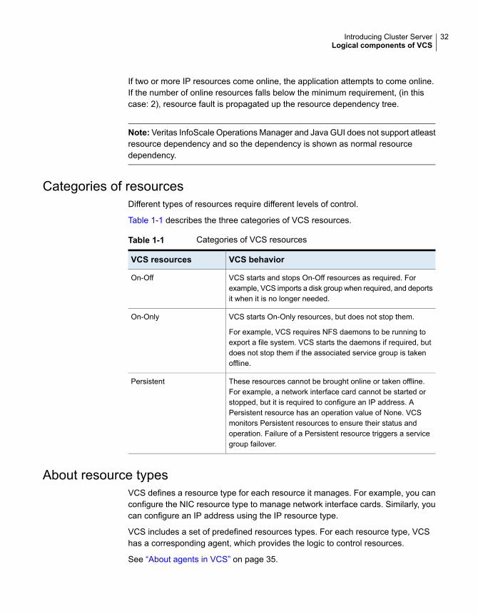
If two or more IP resources come online, the application attempts to come online.If the number of online resources falls below the minimum requirement, (in thiscase: 2), resource fault is propagated up the resource dependency tree.
Note: Veritas InfoScale Operations Manager and Java GUI does not support atleastresource dependency and so the dependency is shown as normal resourcedependency.
Categories of resourcesDifferent types of resources require different levels of control.
Table 1-1 describes the three categories of VCS resources.
Table 1-1 Categories of VCS resources
VCS behaviorVCS resources
VCS starts and stops On-Off resources as required. Forexample, VCS imports a disk group when required, and deportsit when it is no longer needed.
On-Off
VCS starts On-Only resources, but does not stop them.
For example, VCS requires NFS daemons to be running toexport a file system. VCS starts the daemons if required, butdoes not stop them if the associated service group is takenoffline.
On-Only
These resources cannot be brought online or taken offline.For example, a network interface card cannot be started orstopped, but it is required to configure an IP address. APersistent resource has an operation value of None. VCSmonitors Persistent resources to ensure their status andoperation. Failure of a Persistent resource triggers a servicegroup failover.
Persistent
About resource typesVCS defines a resource type for each resource it manages. For example, you canconfigure the NIC resource type to manage network interface cards. Similarly, youcan configure an IP address using the IP resource type.
VCS includes a set of predefined resources types. For each resource type, VCShas a corresponding agent, which provides the logic to control resources.
See “About agents in VCS” on page 35.
32Introducing Cluster ServerLogical components of VCS

About service groupsA service group is a virtual container that contains all the hardware and softwareresources that are required to run the managed application. Service groups allowVCS to control all the hardware and software resources of the managed applicationas a single unit. When a failover occurs, resources do not fail over individually; theentire service group fails over. If more than one service group is on a system, agroup can fail over without affecting the others.
Figure 1-4 shows a typical database service group.
Figure 1-4 Typical database service group
Application
Network
IP AddressFile System
Disk Group
A single node can host any number of service groups, each providing a discreteservice to networked clients. If the server crashes, all service groups on that nodemust be failed over elsewhere.
Service groups can be dependent on each other. For example, a managedapplication might be a finance application that is dependent on a databaseapplication. Because the managed application consists of all components that arerequired to provide the service, service group dependencies create more complexmanaged applications. When you use service group dependencies, the managedapplication is the entire dependency tree.
See “About service group dependencies” on page 381.
Types of service groupsVCS service groups fall in three main categories: failover, parallel, and hybrid.
About failover service groupsA failover service group runs on one system in the cluster at a time. Failover groupsare used for most applications that do not support multiple systems to simultaneouslyaccess the application’s data.
33Introducing Cluster ServerLogical components of VCS

About parallel service groupsA parallel service group runs simultaneously on more than one system in the cluster.A parallel service group is more complex than a failover group. Parallel servicegroups are appropriate for applications that manage multiple application instancesthat run simultaneously without data corruption.
About hybrid service groupsA hybrid service group is for replicated data clusters and is a combination of thefailover and parallel service groups. It behaves as a failover group within a systemzone or site and a parallel group across system zones or site.
A hybrid service group cannot fail over across system zones. VCS allows a switchoperation on a hybrid group only if both systems are within the same system zoneor site. If no systems exist within a zone for failover, VCS calls the nofailover triggeron the lowest numbered node.
See “About service group dependencies” on page 381.
See “About the nofailover event trigger” on page 426.
About the ClusterService groupThe ClusterService group is a special purpose service group, which containsresources that are required by VCS components.
The group contains resources for the following items:
■ Notification
■ Wide-area connector (WAC) process, which is used in global clusters
By default, the ClusterService group can fail over to any node despite restrictionssuch as the node being frozen. However, if you disable the AutoAddSystemToCSGattribute, you can control the nodes that are included in the SystemList. TheClusterService group is the first service group to come online and cannot beautodisabled. The ClusterService group comes online on the first node thattransitions to the running state. The VCS engine discourages the action of takingthe group offline manually.
About the cluster UUIDWhen you install VCS using the product installer, the installer generates a universallyunique identifier (UUID) for the cluster. This value is the same across all the nodesin the cluster. The value is defined in the ClusterUUID or CID attribute.
See “Cluster attributes” on page 722.
34Introducing Cluster ServerLogical components of VCS

If you do not use the product installer to install VCS, you must run the uuidconfig.plutility to configure the UUID for the cluster.
See “Configuring and unconfiguring the cluster UUID value” on page 155.
About agents in VCSAgents are multi-threaded processes that provide the logic to manage resources.VCS has one agent per resource type. The agent monitors all resources of thattype; for example, a single IP agent manages all IP resources.
When the agent starts, it obtains the necessary configuration information from theVCS engine. It then periodically monitors the resources, and updates the VCSengine with the resource status. The agents that support Intelligent MonitoringFramework (IMF) also monitors the resources asynchronously. These agents registerwith the IMF notification module for resource state change notifications. EnablingIMF for process-based and mount-based agents can give you significantperformance benefits in terms of system resource utilization and also aid fasterfailover of applications.
See “About resource monitoring” on page 37.
The action to bring a resource online or take it offline differs significantly for eachresource type. For example, when you bring a disk group online, it requires importingthe disk group. But, when you bring a database online, it requires that you start thedatabase manager process and issue the appropriate startup commands.
VCS monitors resources when they are online and offline to ensure that they arenot started on systems where they are not supposed to run. For this reason, VCSstarts the agent for any resource that is configured to run on a system when thecluster is started. If no resources of a particular type are configured, the agent isnot started. For example, if no Oracle resources exist in your configuration, theOracle agent is not started on the system.
Certain agents can identify when an application has been intentionally shut downoutside of VCS control. For agents that support this functionality, if an administratorintentionally shuts down an application outside of VCS control, VCS does not treatit as a fault. VCS sets the service group state as offline or partial, which dependson the state of other resources in the service group.
This feature allows administrators to stop applications that do not cause a failover.The feature is available for V51 agents. Agent versions are independent of VCSversions. For example, VCS 6.0 can run V40, V50, V51, and V52 agents forbackward compatibility.
See “VCS behavior for resources that support the intentional offline functionality”on page 343.
35Introducing Cluster ServerLogical components of VCS

About agent functionsAgents carry out specific functions on resources. The functions an agent performsare called entry points.
For details on agent functions, see the Cluster Server Agent Developer’s Guide.
Table 1-2 describes the agent functions.
Table 1-2 Agent functions
RoleAgent functions
Brings a specific resource ONLINE from an OFFLINE state.Online
Takes a resource from an ONLINE state to an OFFLINE state.Offline
Tests the status of a resource to determine if the resource is online oroffline.
The function runs at the following times:
■ During initial node startup, to probe and determine the status of allresources on the system.
■ After every online and offline operation.■ Periodically, to verify that the resource remains in its correct state.
Under normal circumstances, the monitor entry point is run every60 seconds when a resource is online. The entry point is run every300 seconds when a resource is expected to be offline.
■ When you probe a resource using the following command:# hares -probe res_name -sys system_name.
Monitor
Initializes the agent to interface with the IMF notification module. Thisfunction runs when the agent starts up.
imf_init
Gets notification about resource state changes. This function runs afterthe agent initializes with the IMF notification module. This functioncontinuously waits for notification and takes action on the resourceupon notification.
imf_getnotification
Registers or unregisters resource entities with the IMF notificationmodule. For example, the function registers the PID for online monitoringof a process. This function runs for each resource after the resourcegoes into steady state (online or offline).
imf_register
36Introducing Cluster ServerLogical components of VCS

Table 1-2 Agent functions (continued)
RoleAgent functions
Cleans up after a resource fails to come online, fails to go offline, orfails to detect as ONLINE when resource is in an ONLINE state. Theclean entry point is designed to clean up after an application fails. Thefunction ensures that the host system is returned to a valid state. Forexample, the clean function may remove shared memory segments orIPC resources that are left behind by a database.
Clean
Performs actions that can be completed in a short time and which areoutside the scope of traditional activities such as online and offline.Some agents have predefined action scripts that you can run by invokingthe action function.
Action
Retrieves specific information for an online resource.
The retrieved information is stored in the resource attributeResourceInfo. This function is invoked periodically by the agentframework when the resource type attribute InfoInterval is set to anon-zero value. The InfoInterval attribute indicates the period afterwhich the info function must be invoked. For example, the Mount agentmay use this function to indicate the space available on the file system.
To see the updated information, you can invoke the info agent functionexplicitly from the command line interface by running the followingcommand:
hares -refreshinfo res [-sys system] -clus cluster| -localclus
Info
About resource monitoringVCS agents poll the resources periodically based on the monitor interval (in seconds)value that is defined in the MonitorInterval or in the OfflineMonitorInterval resourcetype attributes. After each monitor interval, VCS invokes the monitor agent functionfor that resource. For example, for process offline monitoring, the process agent'smonitor agent function corresponding to each process resource scans the processtable in each monitor interval to check whether the process has come online. Forprocess online monitoring, the monitor agent function queries the operating systemfor the status of the process id that it is monitoring. In case of the mount agent, themonitor agent function corresponding to each mount resource checks if the blockdevice is mounted on the mount point or not. In order to determine this, the monitorfunction does operations such as mount table scans or runs statfs equivalents.
With intelligent monitoring framework (IMF), VCS supports intelligent resourcemonitoring in addition to poll-based monitoring. IMF is an extension to the VCS
37Introducing Cluster ServerLogical components of VCS
agent framework. You can enable or disable the intelligent monitoring functionalityof the VCS agents that are IMF-aware. For a list of IMF-aware agents, see theCluster Server Bundled Agents Reference Guide.
See “How intelligent resource monitoring works” on page 39.
See “Enabling and disabling intelligent resource monitoring for agents manually”on page 140.
See “Enabling and disabling IMF for agents by using script” on page 142.
Poll-based monitoring can consume a fairly large percentage of system resourcessuch as CPU and memory on systems with a huge number of resources. This notonly affects the performance of running applications, but also places a limit on howmany resources an agent can monitor efficiently.
However, with IMF-based monitoring you can either eliminate poll-based monitoringcompletely or reduce its frequency. For example, for process offline and onlinemonitoring, you can completely avoid the need for poll-based monitoring withIMF-based monitoring enabled for processes. Similarly for vxfs mounts, you caneliminate the poll-based monitoring with IMF monitoring enabled. Such reductionin monitor footprint will make more system resources available for other applicationsto consume.
Note: Intelligent Monitoring Framework for mounts is supported only for the VxFS,CFS, and NFS mount types.
With IMF-enabled agents, VCS will be able to effectively monitor larger number ofresources.
Thus, intelligent monitoring has the following benefits over poll-based monitoring:
■ Provides faster notification of resource state changes
■ Reduces VCS system utilization due to reduced monitor function footprint
■ Enables VCS to effectively monitor a large number of resources
Consider enabling IMF for an agent in the following cases:
■ You have a large number of process resources or mount resources under VCScontrol.
■ You have any of the agents that are IMF-aware.
For information about IMF-aware agents, see the following documentation:
■ See the Cluster Server Bundled Agents Reference Guide for details on whetheryour bundled agent is IMF-aware.
38Introducing Cluster ServerLogical components of VCS

■ See the Storage Foundation Cluster File System High Availability InstallationGuide for IMF-aware agents in CFS environments.
How intelligent resource monitoring worksWhen an IMF-aware agent starts up, the agent initializes with the IMF notificationmodule. After the resource moves to a steady state, the agent registers the detailsthat are required to monitor the resource with the IMF notification module. Forexample, the process agent registers the PIDs of the processes with the IMFnotification module. The agent's imf_getnotification function waits for any resourcestate changes. When the IMF notification module notifies the imf_getnotificationfunction about a resource state change, the agent framework runs the monitor agentfunction to ascertain the state of that resource. The agent notifies the state changeto VCS which takes appropriate action.
A resource moves into a steady state when any two consecutive monitor agentfunctions report the state as ONLINE or as OFFLINE. The following are a fewexamples of how steady state is reached.
■ When a resource is brought online, a monitor agent function is scheduled afterthe online agent function is complete. Assume that this monitor agent functionreports the state as ONLINE. The next monitor agent function runs after a timeinterval specified by the MonitorInterval attribute. If this monitor agent functiontoo reports the state as ONLINE, a steady state is achieved because twoconsecutive monitor agent functions reported the resource state as ONLINE.After the second monitor agent function reports the state as ONLINE, theregistration command for IMF is scheduled. The resource is registered with theIMF notification module and the resource comes under IMF control.The defaultvalue of MonitorInterval is 60 seconds.A similar sequence of events applies for taking a resource offline.
■ Assume that IMF is disabled for an agent type and you enable IMF for the agenttype when the resource is ONLINE. The next monitor agent function occurs aftera time interval specified by MonitorInterval. If this monitor agent function againreports the state as ONLINE, a steady state is achieved because two consecutivemonitor agent functions reported the resource state as ONLINE.A similar sequence of events applies if the resource is OFFLINE initially andthe next monitor agent function also reports the state as OFFLINE after youenable IMF for the agent type.
See “About the IMF notification module” on page 44.
About Open IMFThe Open IMF architecture builds further upon the IMF functionality by enablingyou to get notifications about events that occur in user space.
39Introducing Cluster ServerLogical components of VCS

The architecture uses an IMF daemon (IMFD) that collects notifications from theuser space notification providers (USNPs) and passes the notifications to the AMFdriver, which in turn passes these on to the appropriate agent. IMFD starts on thefirst registration with IMF by an agent that requires Open IMF.
The Open IMF architecture provides the following benefits:
■ IMF can group events of different types under the same VCS resource and isthe central notification provider for kernel space events and user space events.
■ More agents can become IMF-aware by leveraging the notifications that areavailable only from user space.
■ Agents can get notifications from IMF without having to interact with USNPs.
For example, Open IMF enables the AMF driver to get notifications from vxnotify,the notification provider for Veritas Volume Manager. The AMF driver passes thesenotifications on to the DiskGroup agent. For more information on the DiskGroupagent, see the Cluster Server Bundled Agents Reference Guide.
Agent classificationsThe different kinds of agents that work with VCS include bundled agents, enterpriseagents, and custom agents.
About bundled agentsBundled agents are packaged with VCS. They include agents for Disk, Mount, IP,and various other resource types.
See the Cluster Server Bundled Agents Reference Guide.
About enterprise agentsEnterprise agents control third party applications. These include agents for Oracle,Sybase, and DB2.
See the following documentation for more information:
■ Cluster Server Agent for Oracle Installation and Configuration Guide
■ Cluster Server Agent for Sybase Installation and Configuration Guide
■ Cluster Server Agent for DB2 Installation and Configuration Guide
About custom agentsCustom agents are agents that customers or Veritas consultants develop. Typically,agents are developed because the user requires control of an application that thecurrent bundled or enterprise agents do not support.
40Introducing Cluster ServerLogical components of VCS

See the Cluster Server Agent Developer’s Guide.
VCS agent frameworkThe VCS agent framework is a set of common, predefined functions that arecompiled into each agent. These functions include the ability to connect to theVeritas High Availability Engine (HAD) and to understand common configurationattributes. The agent framework frees the developer from developing functions forthe cluster; the developer instead can focus on controlling a specific resource type.
VCS agent framework also includes IMF which enables asynchronous monitoringof resources and instantaneous state change notifications.
See “About resource monitoring” on page 37.
For more information on developing agents, see the Cluster Server AgentDeveloper’s Guide.
About cluster control, communications, and membershipCluster communications ensure that VCS is continuously aware of the status ofeach system’s service groups and resources. They also enable VCS to recognizewhich systems are active members of the cluster, which have joined or left thecluster, and which have failed.
See “About the high availability daemon (HAD)” on page 41.
See “About the HostMonitor daemon” on page 42.
See “About Group Membership Services and Atomic Broadcast (GAB)” on page 43.
See “About Low Latency Transport (LLT)” on page 43.
See “About the I/O fencing module” on page 44.
See “About the IMF notification module” on page 44.
About the high availability daemon (HAD)The VCS high availability daemon (HAD) runs on each system.
Also known as the Veritas High Availability Engine, HAD is responsible for thefollowing functions:
■ Builds the running cluster configuration from the configuration files
■ Distributes the information when new nodes join the cluster
■ Responds to operator input
■ Takes corrective action when something fails.
41Introducing Cluster ServerLogical components of VCS

The engine uses agents to monitor and manage resources. It collects informationabout resource states from the agents on the local system and forwards it to allcluster members.
The local engine also receives information from the other cluster members to updateits view of the cluster. HAD operates as a replicated state machine (RSM). Theengine that runs on each node has a completely synchronized view of the resourcestatus on each node. Each instance of HAD follows the same code path for correctiveaction, as required.
The RSM is maintained through the use of a purpose-built communications package.The communications package consists of the protocols Low Latency Transport(LLT) and Group Membership Services and Atomic Broadcast (GAB).
See “About inter-system cluster communications” on page 215.
The hashadow process monitors HAD and restarts it when required.
About the HostMonitor daemonVCS also starts HostMonitor daemon when the VCS engine comes up. The VCSengine creates a VCS resource VCShm of type HostMonitor and a VCShmg servicegroup. The VCS engine does not add these objects to the main.cf file. Do not modifyor delete these VCS components. VCS uses the HostMonitor daemon to monitorthe resource utilization of CPU, Memory, and Swap. VCS reports to the engine logif the resources cross the threshold limits that are defined for the resources. TheHostMonitor daemon also monitors the available capacity of CPU, memory, andSwap in absolute terms, enabling the VCS engine to make dynamic decisions aboutfailing over an application to the biggest available or best suitable system.
VCS deletes user-defined VCS objects that use the HostMonitor object names. Ifyou had defined the following objects in the main.cf file using the reserved wordsfor the HostMonitor daemon, then VCS deletes these objects when the VCS enginestarts:
■ Any group that you defined as VCShmg along with all its resources.
■ Any resource type that you defined as HostMonitor along with all the resourcesof such resource type.
■ Any resource that you defined as VCShm.
See “VCS keywords and reserved words” on page 70.
You can control the behavior of the HostMonitor daemon using the Statisticsattribute.
See “Cluster attributes” on page 722.
42Introducing Cluster ServerLogical components of VCS
About GroupMembership Services and Atomic Broadcast(GAB)The Group Membership Services and Atomic Broadcast protocol (GAB) isresponsible for the following cluster membership and cluster communicationsfunctions:
■ Cluster MembershipGAB maintains cluster membership by receiving input on the status of theheartbeat from each node by LLT. When a system no longer receives heartbeatsfrom a peer, it marks the peer as DOWN and excludes the peer from the cluster.In VCS, memberships are sets of systems participating in the cluster.
VCS has the following types of membership:
■ A regular membership includes systems that communicate with each otheracross more than one network channel.
■ A jeopardy membership includes systems that have only one privatecommunication link.
■ A visible membership includes systems that have GAB running but the GABclient is no longer registered with GAB.
■ Cluster CommunicationsGAB’s second function is reliable cluster communications. GAB providesguaranteed delivery of point-to-point and broadcast messages to all nodes. TheVeritas High Availability Engine uses a private IOCTL (provided by GAB) to tellGAB that it is alive.
About Low Latency Transport (LLT)VCS uses private network communications between cluster nodes for clustermaintenance. The Low Latency Transport functions as a high-performance,low-latency replacement for the IP stack, and is used for all cluster communications.Veritas recommends at least two independent networks between all cluster nodes.
For detailed information on the setting up networks, seeCluster Server Configurationand Upgrade Guide.
These networks provide the required redundancy in the communication path andenable VCS to differentiate between a network failure and a system failure.
LLT has the following two major functions:
■ Traffic distributionLLT distributes (load balances) internode communication across all availableprivate network links. This distribution means that all cluster communicationsare evenly distributed across all private network links (maximum eight) for
43Introducing Cluster ServerLogical components of VCS

performance and fault resilience. If a link fails, traffic is redirected to the remaininglinks.
■ HeartbeatLLT is responsible for sending and receiving heartbeat traffic over network links.The Group Membership Services function of GAB uses this heartbeat todetermine cluster membership.
About the I/O fencing moduleThe I/O fencing module implements a quorum-type functionality to ensure that onlyone cluster survives a split of the private network. I/O fencing also provides theability to perform SCSI-3 persistent reservations on failover. The shared disk groupsoffer complete protection against data corruption by nodes that are assumed to beexcluded from cluster membership.
See “About the I/O fencing algorithm” on page 247.
About the IMF notification moduleThe notification module of Intelligent Monitoring Framework (IMF) is theAsynchronous Monitoring Framework (AMF).
AMF is a kernel driver which hooks into system calls and other kernel interfaces ofthe operating system to get notifications on various events such as:
■ When a process starts or stops.
■ When a block device gets mounted or unmounted from a mount point.
■ When a WPAR starts or stops.
AMF also interacts with the Intelligent Monitoring Framework Daemon (IMFD) toget disk group related notifications. AMF relays these notifications to various VCSAgents that are enabled for intelligent monitoring.
See “About Open IMF” on page 39.
WPAR agent also uses AMF kernel driver for asynchronous event notifications.
See “About resource monitoring” on page 37.
See “About cluster control, communications, and membership” on page 41.
About security servicesVCS uses the VCS Authentication Service to provide secure communication betweencluster nodes. VCS uses digital certificates for authentication and uses SSL toencrypt communication over the public network.
44Introducing Cluster ServerLogical components of VCS

In secure mode:
■ VCS uses platform-based authentication.
■ VCS does not store user passwords.
■ All VCS users are system and domain users and are configured usingfully-qualified user names. For example, administrator@vcsdomain. VCSprovides a single sign-on mechanism, so authenticated users do not need tosign on each time to connect to a cluster.
For secure communication, VCS components acquire credentials from theauthentication broker that is configured on the local system. In VCS 6.0 and later,a root and authentication broker is automatically deployed on each node when asecure cluster is configured. The acquired certificate is used during authenticationand is presented to clients for the SSL handshake.
VCS and its components specify the account name and the domain in the followingformat:
■ HAD Account
name = HAD
domain = VCS_SERVICES@Cluster UUID
■ CmdServer
name = CMDSERVER
domain = VCS_SERVICES@Cluster UUID
For instructions on how to set up Security Services while setting up the cluster, seethe Cluster Server installation documentation.
See “Enabling and disabling secure mode for the cluster” on page 161.
Components for administering VCSVCS provides several components to administer clusters.
Table 1-3 describes the components that VCS provides to administer clusters:
45Introducing Cluster ServerLogical components of VCS

Table 1-3 VCS components to administer clusters
DescriptionVCScomponents
A Web-based graphical user interface for monitoring and administeringthe cluster.
Install the Veritas InfoScale Operations Manager on a managementserver outside the cluster to manage multiple clusters.
See the Veritas InfoScale Operations Manager documentation for moreinformation.
Veritas InfoScaleOperationsManager
A cross-platform Java-based graphical user interface that providescomplete administration capabilities for your cluster. The console runson any system inside or outside the cluster, on any operating systemthat supports Java. You cannot use Java Console if the externalcommunication port for VCS is not open. By default, the externalcommunication port for VCS is 14141.
Note: Veritas Technologies recommends Veritas InfoScale OperationsManager be used as the graphical user interface to monitor andadminister the cluster. Cluser Manager (Java Console) may not supportfeatures released in VCS 6.0 and later versions.
Cluster Manager(Java Console)
The VCS command-line interface provides a comprehensive set ofcommands for managing and administering the cluster.
See “About administering VCS from the command line” on page 87.
VCS command lineinterface (CLI)
About Veritas InfoScale Operations ManagerVeritas InfoScale Operations Manager provides a centralized management consolefor Veritas InfoScale products. You can use Veritas InfoScale Operations Managerto monitor, visualize, and manage storage resources and generate reports.
Veritas recommends using Veritas InfoScale Operations Manager to manageStorage Foundation and Cluster Server environments.
You can download Veritas InfoScale Operations Manager fromhttps://sort.veritas.com/.
Refer to the Veritas InfoScale Operations Manager documentation for installation,upgrade, and configuration instructions.
46Introducing Cluster ServerLogical components of VCS

Putting the pieces togetherIn this example, a two-node cluster exports an NFS file system to clients. Bothnodes are connected to shared storage, which enables them to access thedirectories being shared. A single service group, NFS_Group, fails over betweenSystem A and System B, as necessary.
The Veritas High Availability Engine (HAD) reads the configuration file, determineswhat agents are required to control the resources in the service group, and startsthe agents. HAD uses resource dependencies to determine the order in which tobring the resources online. VCS issues online commands to the correspondingagents in the correct order.
Figure 1-5 shows a dependency graph for the sample NFS group.
Figure 1-5
Share
NFSRestart
IP
DiskGroup
MountNFS/Proxy
NFSRestart
LockMount
VCS starts the agents for DiskGroup, Mount, Share, NFS, NIC, IP, and NFSRestarton all systems that are configured to run NFS_Group.
The resource dependencies are configured as follows:
■ The /home file system (configured as a Mount resource), requires that the diskgroup (configured as a DiskGroup resource) is online before you mount.
■ The lower NFSRestart resource requires that the file system is mounted andthat the NFS daemons (NFS) are running.
■ The NFS export of the home file system (Share) requires that the lowerNFSRestart resource is up.
47Introducing Cluster ServerPutting the pieces together
■ The high availability IP address, nfs_IP, requires that the file system (Share) isshared and that the network interface (NIC) is up.
■ The upper NFSRestart resource requires that the IP address is up.
■ The NFS daemons and the disk group have no child dependencies, so they canstart in parallel.
■ The NIC resource is a persistent resource and does not require starting.
You can configure the service group to start automatically on either node in thepreceding example. It then can move or fail over to the second node on commandor automatically if the first node fails. On failover or relocation, to make the resourcesoffline on the first node, VCS begins at the top of the graph. When it starts them onthe second node, it begins at the bottom.
48Introducing Cluster ServerPutting the pieces together

About cluster topologiesThis chapter includes the following topics:
■ Basic failover configurations
■ About advanced failover configurations
■ Cluster topologies and storage configurations
Basic failover configurationsThe basic failover configurations include asymmetric, symmetric, and N-to-1.
Asymmetric or active / passive configurationIn an asymmetric configuration, an application runs on a primary server. A dedicatedredundant server is present to take over on any failure. The redundant server isnot configured to perform any other functions.
Figure 2-1 shows failover within an asymmetric cluster configuration, where adatabase application is moved, or failed over, from the master to the redundantserver.
2Chapter

Figure 2-1 Asymmetric failover
Before Failover After Failover
ApplicationApplication
This configuration is the simplest and most reliable. The redundant server is onstand-by with full performance capability. If other applications are running, theypresent no compatibility issues.
Symmetric or active / active configurationIn a symmetric configuration, each server is configured to run a specific applicationor service and provide redundancy for its peer. In this example, each server runsone application service group. When a failure occurs, the surviving server hostsboth application groups.
Figure 2-2 shows failover within a symmetric cluster configuration.
Figure 2-2 Symmetric failover
Before Failover After Failover
Application1 Application2Application1
Application2
Symmetric configurations appear more efficient in terms of hardware utilization. Inthe asymmetric example, the redundant server requires only as much processorpower as its peer. On failover, performance remains the same. In the symmetricexample, the redundant server requires adequate processor power to run theexisting application and the new application it takes over.
50About cluster topologiesBasic failover configurations

Further issues can arise in symmetric configurations when multiple applicationsthat run on the same system do not co-exist properly. Some applications work wellwith multiple copies started on the same system, but others fail. Issues also canarise when two applications with different I/O and memory requirements run on thesame system.
About N-to-1 configurationAn N-to-1 failover configuration reduces the cost of hardware redundancy and stillprovides a potential, dedicated spare. In an asymmetric configuration no performancepenalty exists. No issues exist with multiple applications running on the samesystem; however, the drawback is the 100 percent redundancy cost at the serverlevel.
Figure 2-3 shows an N to 1 failover configuration.
Figure 2-3 N-to-1 configuration
ApplicationApplicationApplicationApplication
Redundant Server
An N-to-1 configuration is based on the concept that multiple, simultaneous serverfailures are unlikely; therefore, a single redundant server can protect multiple activeservers. When a server fails, its applications move to the redundant server. Forexample, in a 4-to-1 configuration, one server can protect four servers. Thisconfiguration reduces redundancy cost at the server level from 100 percent to 25percent. In this configuration, a dedicated, redundant server is cabled to all storageand acts as a spare when a failure occurs.
The problem with this design is the issue of failback. When the failed server isrepaired, you must manually fail back all services that are hosted on the failoverserver to the original server. The failback action frees the spare server and restoresredundancy to the cluster.
Figure 2-4 shows an N to 1 failover requiring failback.
51About cluster topologiesBasic failover configurations

Figure 2-4 N-to-1 failover requiring failback
Application
Redundant Server
Application Application
Most shortcomings of early N-to-1 cluster configurations are caused by the limitationsof storage architecture. Typically, it is impossible to connect more than two hoststo a storage array without complex cabling schemes and their inherent reliabilityproblems, or expensive arrays with multiple controller ports.
About advanced failover configurationsAdvanced failover configuration for VCS include N + 1 and N-to-N configurations.
About the N + 1 configurationWith the capabilities introduced by storage area networks (SANs), you cannot onlycreate larger clusters, you can also connect multiple servers to the same storage.
Figure 2-5 shows an N+1 cluster failover configuration.
Figure 2-5 N+1 configuration
Spare
Service Group
Service Group
Service Group
Service Group
52About cluster topologiesAbout advanced failover configurations

A dedicated, redundant server is no longer required in the configuration. Insteadof N-to-1 configurations, you can use an N+1 configuration. In advanced N+1configurations, an extra server in the cluster is spare capacity only.
When a server fails, the application service group restarts on the spare. After theserver is repaired, it becomes the spare. This configuration eliminates the need fora second application failure to fail back the service group to the primary system.Any server can provide redundancy to any other server.
Figure 2-6 shows an N+1 cluster failover configuration requiring failback.
Figure 2-6 N+1 cluster failover configuration requiring failback
Service Group
Service Group
Service Group
Service Group
About the N-to-N configurationAn N-to-N configuration refers to multiple service groups that run on multiple servers,with each service group capable of being failed over to different servers. Forexample, consider a four-node cluster in which each node supports three criticaldatabase instances.
Figure 2-7 shows an N to N cluster failover configuration.
53About cluster topologiesAbout advanced failover configurations

Figure 2-7 N-to-N configuration
SG
SG
SG = Service Group
SG
SG
SG
SG
SG
SG
SG
SG
SG
SG
SG
SG
SG
SG
If any node fails, each instance is started on a different node. this action ensuresthat no single node becomes overloaded. This configuration is a logical evolutionof N + 1; it provides cluster standby capacity instead of a standby server.
N-to-N configurations require careful testing to ensure that all applications arecompatible. You must specify a list of systems on which a service group is allowedto run in the event of a failure.
Cluster topologies and storage configurationsThe commonly-used cluster topologies include the following:
■ Shared storage clusters
■ Campus clusters
■ Shared nothing clusters
■ Replicated data clusters
■ Global clusters
About basic shared storage clusterIn this configuration, a single cluster shares access to a storage device, typicallyover a SAN. You can only start an application on a node with access to the requiredstorage. For example, in a multi-node cluster, any node that is designated to run aspecific database instance must have access to the storage where the database’stablespaces, redo logs, and control files are stored. Such a shared disk architectureis also the easiest to implement and maintain. When a node or application fails, alldata that is required to restart the application on another node is stored on theshared disk.
Figure 2-8 shows a shared disk architecture for a basic cluster.
54About cluster topologiesCluster topologies and storage configurations

Figure 2-8 Shared disk architecture for basic cluster
Service Group
Service Group
Service Group
Service Group
About campus, or metropolitan, shared storage clusterIn a campus environment, you use VCS and Veritas Volume Manager to create acluster that spans multiple datacenters or buildings. Instead of a single storagearray, data is mirrored between arrays by using Veritas Volume Manager. Thisconfiguration provides synchronized copies of data at both sites. This procedure isidentical to mirroring between two arrays in a datacenter; only now it is spread overa distance.
Figure 2-9 shows a campus shared storage cluster.
Figure 2-9 Campus shared storage cluster
SG
SG
SG = Service Group
SG
SG
SG
SG
SG
SG
Site A Site B
Veritas Volume Manager
RAID 1 Mirror of
Reliable Disks
SG SG SG SG SG SG SG SG
55About cluster topologiesCluster topologies and storage configurations

A campus cluster requires two independent network links for heartbeat, two storagearrays each providing highly available disks, and public network connectivity betweenbuildings on same IP subnet. If the campus cluster setup resides on different subnetswith one for each site, then use the VCS DNS agent to handle the network changesor issue the DNS changes manually.
See “ How VCS campus clusters work” on page 530.
About shared nothing clustersSystems in shared nothing clusters do not share access to disks; they maintainseparate copies of data. VCS shared nothing clusters typically have read-only datastored locally on both systems. For example, a pair of systems in a cluster thatincludes a critical Web server, which provides access to a backend database. TheWeb server runs on local disks and does not require data sharing at the Web serverlevel.
Figure 2-10 shows a shared nothing cluster.
Figure 2-10 Shared nothing cluster
About replicated data clustersIn a replicated data cluster no shared disks exist. Instead, a data replication productsynchronizes copies of data between nodes or sites. Replication can take place atthe application, host, and storage levels. Application-level replication products, suchas Oracle DataGuard, maintain consistent copies of data between systems at theSQL or database levels. Host-based replication products, such as Veritas VolumeReplicator, maintain consistent storage at the logical volume level. Storage-basedor array-based replication maintains consistent copies of data at the disk or RAIDLUN level.
Figure 2-11 shows a hybrid shared storage and replicated data cluster, in whichdifferent failover priorities are assigned to nodes according to particular servicegroups.
56About cluster topologiesCluster topologies and storage configurations

Figure 2-11 Shared storage replicated data cluster
Replication
Service Group
You can also configure replicated data clusters without the ability to fail over locally,but this configuration is not recommended.
See “ How VCS replicated data clusters work” on page 521.
About global clustersA global cluster links clusters at separate locations and enables wide-area failoverand disaster recovery.
Local clustering provides local failover for each site or building. Campus andreplicated cluster configurations offer protection against disasters that affect limitedgeographic regions. Large scale disasters such as major floods, hurricanes, andearthquakes can cause outages for an entire city or region. In such situations, youcan ensure data availability by migrating applications to sites located considerabledistances apart.
Figure 2-12 shows a global cluster configuration.
57About cluster topologiesCluster topologies and storage configurations

Figure 2-12 Global cluster
PublicNetwork
SeparateStorage
SeparateStorage
Client Client Client Client
ReplicatedData
ClientsRedirected
ApplicationFailover
OracleGroup
Cluster A Cluster B
OracleGroup
In a global cluster, if an application or a system fails, the application is migrated toanother system within the same cluster. If the entire cluster fails, the application ismigrated to a system in another cluster. Clustering on a global level also requiresthe replication of shared data to the remote site.
58About cluster topologiesCluster topologies and storage configurations
VCS configurationconcepts
This chapter includes the following topics:
■ About configuring VCS
■ VCS configuration language
■ About the main.cf file
■ About the types.cf file
■ About VCS attributes
■ VCS keywords and reserved words
■ VCS environment variables
About configuring VCSWhen you configure VCS, you convey to the Veritas High Availability Engine thedefinitions of the cluster, service groups, resources, and dependencies amongservice groups and resources.
VCS uses the following two configuration files in a default configuration:
■ main.cfDefines the cluster, including services groups and resources.
■ types.cfDefines the resource types.
By default, both files reside in the following directory:
/etc/VRTSvcs/conf/config
3Chapter

Additional files that are similar to types.cf may be present if you enabled agents.OracleTypes.cf, by default, is located at /etc/VRTSagents/ha/conf/Oracle/.
In a VCS cluster, the first system to be brought online reads the configuration fileand creates an internal (in-memory) representation of the configuration. Systemsthat are brought online after the first system derive their information from systemsthat are in the cluster.
You must stop the cluster if you need to modify the files manually. Changes madeby editing the configuration files take effect when the cluster is restarted. The nodewhere you made the changes should be the first node to be brought back online.
VCS configuration languageThe VCS configuration language specifies the makeup of service groups and theirassociated entities, such as resource types, resources, and attributes. Thesespecifications are expressed in configuration files, whose names contain the suffix.cf.
Several ways to generate configuration files are as follows:
■ Use the Web-based Veritas InfoScale Operations Manager.
■ Use Cluster Manager (Java Console).
■ Use the command-line interface.
■ If VCS is not running, use a text editor to create and modify the files.
■ Use the VCS simulator on a Windows system to create the files.
About the main.cf fileThe format of the main.cf file comprises include clauses and definitions for thecluster, systems, service groups, and resources. The main.cf file also includesservice group and resource dependency clauses.
Table 3-1 describes some of the components of the main.cf file:
60VCS configuration conceptsVCS configuration language

Table 3-1 Components of the main.cf file
DescriptionComponents of main.cffile
Include clauses incorporate additional configuration files intomain.cf. These additional files typically contain type definitions,including the types.cf file. Typically, custom agents add typedefinitions in their own files.
include "types.cf"
See “Including multiple .cf files in main.cf” on page 64.
Include clauses
Defines the attributes of the cluster, the cluster name and thenames of the cluster users.
cluster demo (UserNames = { admin = cDRpdxPmHzpS })
See “Cluster attributes” on page 722.
Cluster definition
Lists the systems designated as part of the cluster. Thesystem names must match the name returned by thecommand uname -a.
Each service group can be configured to run on a subset ofsystems defined in this section.
system Server1system Server2
See System attributes on page 707.
System definition
Service group definitions in main.cf comprise the attributesof a particular service group.
group NFS_group1 (SystemList = { Server1=0, Server2=1 }AutoStartList = { Server1 }
)
See “Service group attributes” on page 680.
See “About the SystemList attribute” on page 63.
Service group definition
61VCS configuration conceptsAbout the main.cf file
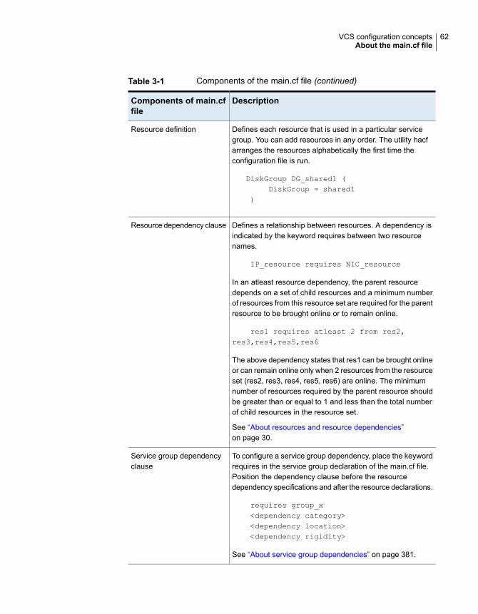
Table 3-1 Components of the main.cf file (continued)
DescriptionComponents of main.cffile
Defines each resource that is used in a particular servicegroup. You can add resources in any order. The utility hacfarranges the resources alphabetically the first time theconfiguration file is run.
DiskGroup DG_shared1 (DiskGroup = shared1
)
Resource definition
Defines a relationship between resources. A dependency isindicated by the keyword requires between two resourcenames.
IP_resource requires NIC_resource
In an atleast resource dependency, the parent resourcedepends on a set of child resources and a minimum numberof resources from this resource set are required for the parentresource to be brought online or to remain online.
res1 requires atleast 2 from res2,res3,res4,res5,res6
The above dependency states that res1 can be brought onlineor can remain online only when 2 resources from the resourceset (res2, res3, res4, res5, res6) are online. The minimumnumber of resources required by the parent resource shouldbe greater than or equal to 1 and less than the total numberof child resources in the resource set.
See “About resources and resource dependencies”on page 30.
Resource dependency clause
To configure a service group dependency, place the keywordrequires in the service group declaration of the main.cf file.Position the dependency clause before the resourcedependency specifications and after the resource declarations.
requires group_x<dependency category><dependency location><dependency rigidity>
See “About service group dependencies” on page 381.
Service group dependencyclause
62VCS configuration conceptsAbout the main.cf file

Note: Sample configurations for components of global clusters are listed separately.
See “ VCS global clusters: The building blocks” on page 463.
About the SystemList attributeThe SystemList attribute designates all systems where a service group can comeonline. By default, the order of systems in the list defines the priority of systemsthat are used in a failover. For example, the following definition configures SystemAto be the first choice on failover, followed by SystemB, and then by SystemC.
SystemList = { SystemA, SystemB, SystemC }
You can assign system priority explicitly in the SystemList attribute by assigningnumeric values to each system name. For example:
SystemList = { SystemA = 0, SystemB = 1, SystemC = 2 }
If you do not assign numeric priority values, VCS assigns a priority to the systemwithout a number by adding 1 to the priority of the preceding system. For example,if the SystemList is defined as follows, VCS assigns the values SystemA = 0,SystemB = 2, SystemC = 3.
SystemList = { SystemA, SystemB = 2, SystemC }
Note that a duplicate numeric priority value may be assigned in some situations:
SystemList = { SystemA, SystemB=0, SystemC }
The numeric values assigned are SystemA = 0, SystemB = 0, SystemC = 1.
To avoid this situation, do not assign any numbers or assign different numbers toeach system in SystemList.
Initial configurationWhen VCS is installed, a basic main.cf configuration file is created with the clustername, systems in the cluster, and a Cluster Manager user named admin with thepassword password.
The following is an example of the main.cf for cluster demo and systems SystemAand SystemB.
include "types.cf"
cluster demo (
UserNames = { admin = cDRpdxPmHzpS }
)
63VCS configuration conceptsAbout the main.cf file

system SystemA (
)
system SystemB (
)
Including multiple .cf files in main.cfYou may choose include several configuration files in the main.cf file. For example:
include "applicationtypes.cf"
include "listofsystems.cf"
include "applicationgroup.cf"
If you include other .cf files in main.cf, the following considerations apply:
■ Resource type definitions must appear before the definitions of any groups thatuse the resource types.In the following example, the applicationgroup.cf file includes the service groupdefinition for an application. The service group includes resources whoseresource types are defined in the file applicationtypes.cf. In this situation, theapplicationtypes.cf file must appear first in the main.cf file.For example:
include "applicationtypes.cf"
include "applicationgroup.cf"
■ If you define heartbeats outside of the main.cf file and include the heartbeatdefinition file, saving the main.cf file results in the heartbeat definitions gettingadded directly to the main.cf file.
About the types.cf fileThe types.cf file describes standard resource types to the VCS engine; specifically,the data required to control a specific resource.
The types definition performs the following two important functions:
■ Defines the type of values that may be set for each attribute.In the following DiskGroup example, the NumThreads and OnlineRetryLimitattributes are both classified as int, or integer. The DiskGroup, StartVolumesand StopVolumes attributes are defined as str, or strings.See “About attribute data types” on page 66.
■ Defines the parameters that are passed to the VCS engine through the ArgListattribute. The line static str ArgList[] = { xxx, yyy, zzz } defines the order in which
64VCS configuration conceptsAbout the types.cf file

parameters are passed to the agents for starting, stopping, and monitoringresources.
The following example illustrates a DiskGroup resource type definition for AIX:
type DiskGroup (
static keylist SupportedActions = {
"license.vfd", "disk.vfd", "udid.vfd",
"verifyplex.vfd", checkudid, numdisks,
campusplex, volinuse, joindg, splitdg,
getvxvminfo }
static int NumThreads = 1
static int OnlineRetryLimit = 1
static str ArgList[] = { DiskGroup,
StartVolumes, StopVolumes, MonitorOnly,
MonitorReservation, tempUseFence, PanicSystemOnDGLoss,
UmountVolumes, Reservation }
str DiskGroup
boolean StartVolumes = 1
boolean StopVolumes = 1
boolean MonitorReservation = 0
temp str tempUseFence = INVALID
boolean PanicSystemOnDGLoss = 0
int UmountVolumes
str Reservation = ClusterDefault
)
For another example, review the following main.cf and types.cf files that representan IP resource:
■ The high-availability address is configured on the interface, which is defined bythe Device attribute.
■ The IP address is enclosed in double quotes because the string contains periods.See “About attribute data types” on page 66.
■ The VCS engine passes the identical arguments to the IP agent for online,offline, clean, and monitor. It is up to the agent to use the arguments that itrequires. All resource names must be unique in a VCS cluster.
main.cf for AIX:
IP nfs_ip1 (
Device = en0
Address = "192.168.1.201"
Netmask = "255.255.255.0"
)
65VCS configuration conceptsAbout the types.cf file

types.cf for AIX:
type IP (
static keylist RegList = { NetMask }
static keylist SupportedActions = { "device.vfd", "route.vfd" }
static str ArgList[] = { Device, Address, NetMask, Options,
RouteOptions, PrefixLen }
static int ContainerOpts{} = { RunInContainer=0, PassCInfo=1 }
str Device
str Address
str NetMask
str Options
str RouteOptions
int PrefixLen
)
About VCS attributesVCS components are configured by using attributes. Attributes contain data aboutthe cluster, systems, service groups, resources, resource types, agent, andheartbeats if you use global clusters. For example, the value of a service group’sSystemList attribute specifies on which systems the group is configured and thepriority of each system within the group. Each attribute has a definition and a value.Attributes also have default values assigned when a value is not specified.
About attribute data typesVCS supports the following data types for attributes:
A string is a sequence of characters that is enclosed by double quotes.A string can also contain double quotes, but the quotes must beimmediately preceded by a backslash. A backslash is represented ina string as \\. Quotes are not required if a string begins with a letter,and contains only letters, numbers, dashes (-), and underscores (_).
For example, a string that defines a network interface such as en0 doesnot require quotes since it contains only letters and numbers. Howevera string that defines an IP address contains periods and requires quotes-such as: "192.168.100.1".
String
Signed integer constants are a sequence of digits from 0 to 9. Theymay be preceded by a dash, and are interpreted in base 10. Integerscannot exceed the value of a 32-bit signed integer: 21471183247.
Integer
66VCS configuration conceptsAbout VCS attributes

A boolean is an integer, the possible values of which are 0 (false) and1 (true).
Boolean
About attribute dimensionsVCS attributes have the following dimensions:
A scalar has only one value. This is the default dimension.Scalar
A vector is an ordered list of values. Each value is indexed by using apositive integer beginning with zero. Use a comma (,) or a semi-colon(;) to separate values. A set of brackets ([]) after the attribute namedenotes that the dimension is a vector.
For example, an agent’s ArgList is defined as:
static str ArgList[] = { RVG, DiskGroup }
Vector
A keylist is an unordered list of strings, and each string is unique withinthe list. Use a comma (,) or a semi-colon (;) to separate values.
For example, to designate the list of systems on which a service groupwill be started with VCS (usually at system boot):
AutoStartList = {SystemA; SystemB; SystemC}
Keylist
An association is an unordered list of name-value pairs. Use a comma(,) or a semi-colon (;) to separate values.
A set of braces ({}) after the attribute name denotes that an attribute isan association.
For example, to associate the average time and timestamp values withan attribute:
str MonitorTimeStats{} = { Avg = "0", TS = "" }
Association
About attributes and cluster objectsVCS has the following types of attributes, depending on the cluster object theattribute applies to:
Attributes that define the cluster.
For example, ClusterName and ClusterAddress.
Cluster attributes
67VCS configuration conceptsAbout VCS attributes

Attributes that define a service group in the cluster.
For example, Administrators and ClusterList.
Service groupattributes
Attributes that define the system in the cluster.
For example, Capacity and Limits.
System attributes
Attributes that define the resource types in VCS.
These resource type attributes can be further classified as:
■ Type-independentAttributes that all agents (or resource types) understand. Examples:RestartLimit and MonitorInterval; these can be set for any resourcetype.Typically, these attributes are set for all resources of a specific type.For example, setting MonitorInterval for the IP resource type affectsall IP resources.
■ Type-dependentAttributes that apply to a particular resource type. These attributesappear in the type definition file (types.cf) for the agent.Example: The Address attribute applies only to the IP resource type.Attributes defined in the file types.cf apply to all resources of aparticular resource type. Defining these attributes in the main.cf fileoverrides the values in the types.cf file for a specific resource.For example, if you set StartVolumes = 1 for the DiskGroup types.cf,it sets StartVolumes to True for all DiskGroup resources, by default.If you set the value in main.cf , it overrides the value on aper-resource basis.
■ StaticThese attributes apply for every resource of a particular type. Theseattributes are prefixed with the term static and are not included inthe resource’s argument list. You can override some static attributesand assign them resource-specific values.
See “Overriding resource type static attributes” on page 151.
Resource typeattributes
Attributes that define a specific resource.
Some of these attributes are type-independent. For example, you canconfigure the Critical attribute for any resource.
Some resource attributes are type-dependent. For example, the Addressattribute defines the IP address that is associated with the IP resource.These attributes are defined in the main.cf file.
Resourceattributes
Attributes that define a site.
For example, Preference and SystemList.
Site attributes
68VCS configuration conceptsAbout VCS attributes

Attribute scope across systems: global and local attributesAn attribute whose value applies to all systems is global in scope. An attributewhose value applies on a per-system basis is local in scope. The at operator (@)indicates the system to which a local value applies.
An example of local attributes can be found in the following resource type whereIP addresses and routing options are assigned per machine.
MultiNICA mnic (
Device@sys1 = { en0 = "166.98.16.103", en3 = "166.98.16.103" }
Device@sys2 = { en0 = "166.98.16.104", en3 = "166.98.16.104" }
NetMask = "255.255.255.0"
Options = "mtu m"
RouteOptions@sys1 = "-net 192.100.201.0 192.100.13.7"
RouteOptions@sys2 = "-net 192.100.201.1 192.100.13.8"
)
About attribute life: temporary attributesYou can define temporary attributes in the types.cf file. The values of temporaryattributes remain in memory as long as the VCS engine (HAD) is running. Valuesof temporary attributes are not available when HAD is restarted. These attributevalues are not stored in the main.cf file.
You cannot convert temporary attributes to permanent attributes and vice-versa.When you save a configuration, VCS saves temporary attributes and their defaultvalues in the file types.cf.
The scope of these attributes can be local to a node or global across all nodes inthe cluster. You can define local attributes even when the node is not part of acluster.
You can define and modify these attributes only while VCS is running.
See “Adding, deleting, and modifying resource attributes” on page 136.
Size limitations for VCS objectsThe following VCS objects are restricted to 1024 characters.
■ Service group names
■ Resource names
■ Resource type names
■ User names
69VCS configuration conceptsAbout VCS attributes
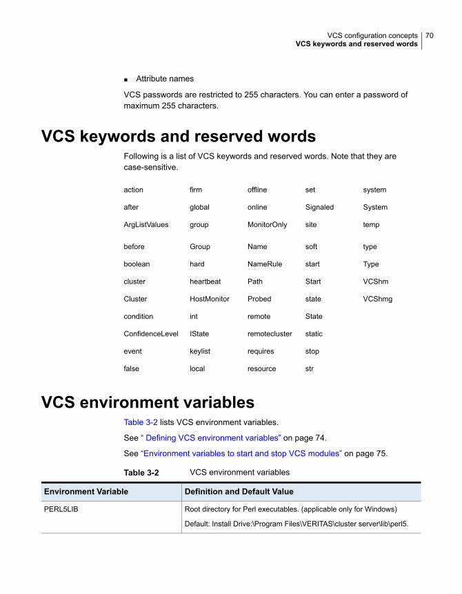
■ Attribute names
VCS passwords are restricted to 255 characters. You can enter a password ofmaximum 255 characters.
VCS keywords and reserved wordsFollowing is a list of VCS keywords and reserved words. Note that they arecase-sensitive.
systemsetofflinefirmaction
SystemSignaledonlineglobalafter
tempsiteMonitorOnlygroupArgListValues
typesoftNameGroupbefore
TypestartNameRulehardboolean
VCShmStartPathheartbeatcluster
VCShmgstateProbedHostMonitorCluster
Stateremoteintcondition
staticremoteclusterIStateConfidenceLevel
stoprequireskeylistevent
strresourcelocalfalse
VCS environment variablesTable 3-2 lists VCS environment variables.
See “ Defining VCS environment variables” on page 74.
See “Environment variables to start and stop VCS modules” on page 75.
Table 3-2 VCS environment variables
Definition and Default ValueEnvironment Variable
Root directory for Perl executables. (applicable only for Windows)
Default: Install Drive:\Program Files\VERITAS\cluster server\lib\perl5.
PERL5LIB
70VCS configuration conceptsVCS keywords and reserved words
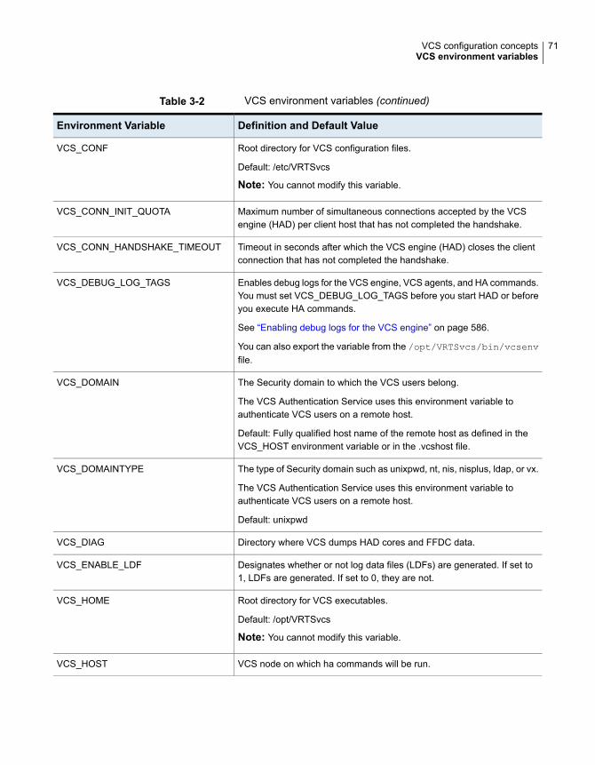
Table 3-2 VCS environment variables (continued)
Definition and Default ValueEnvironment Variable
Root directory for VCS configuration files.
Default: /etc/VRTSvcs
Note: You cannot modify this variable.
VCS_CONF
Maximum number of simultaneous connections accepted by the VCSengine (HAD) per client host that has not completed the handshake.
VCS_CONN_INIT_QUOTA
Timeout in seconds after which the VCS engine (HAD) closes the clientconnection that has not completed the handshake.
VCS_CONN_HANDSHAKE_TIMEOUT
Enables debug logs for the VCS engine, VCS agents, and HA commands.You must set VCS_DEBUG_LOG_TAGS before you start HAD or beforeyou execute HA commands.
See “Enabling debug logs for the VCS engine” on page 586.
You can also export the variable from the /opt/VRTSvcs/bin/vcsenvfile.
VCS_DEBUG_LOG_TAGS
The Security domain to which the VCS users belong.
The VCS Authentication Service uses this environment variable toauthenticate VCS users on a remote host.
Default: Fully qualified host name of the remote host as defined in theVCS_HOST environment variable or in the .vcshost file.
VCS_DOMAIN
The type of Security domain such as unixpwd, nt, nis, nisplus, ldap, or vx.
The VCS Authentication Service uses this environment variable toauthenticate VCS users on a remote host.
Default: unixpwd
VCS_DOMAINTYPE
Directory where VCS dumps HAD cores and FFDC data.VCS_DIAG
Designates whether or not log data files (LDFs) are generated. If set to1, LDFs are generated. If set to 0, they are not.
VCS_ENABLE_LDF
Root directory for VCS executables.
Default: /opt/VRTSvcs
Note: You cannot modify this variable.
VCS_HOME
VCS node on which ha commands will be run.VCS_HOST
71VCS configuration conceptsVCS environment variables
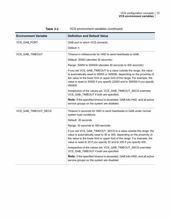
Table 3-2 VCS environment variables (continued)
Definition and Default ValueEnvironment Variable
GAB port to which VCS connects.
Default: h
VCS_GAB_PORT
Timeout in milliseconds for HAD to send heartbeats to GAB.
Default: 30000 (denotes 30 seconds)
Range: 30000 to 300000 (denotes 30 seconds to 300 seconds)
If you set VCS_GAB_TIMEOUT to a value outside the range, the valueis automatically reset to 30000 or 300000, depending on the proximity ofthe value to the lower limit or upper limit of the range. For example, thevalue is reset to 30000 if you specify 22000 and to 300000 if you specify400000.
Irrespective of the values set, VCS_GAB_TIMEOUT_SECS overridesVCS_GAB_TIMEOUT if both are specified.
Note: If the specified timeout is exceeded, GAB kills HAD, and all activeservice groups on the system are disabled.
VCS_GAB_TIMEOUT
Timeout in seconds for HAD to send heartbeats to GAB under normalsystem load conditions.
Default: 30 seconds
Range: 30 seconds to 300 seconds
If you set VCS_GAB_TIMEOUT_SECS to a value outside the range, thevalue is automatically reset to 30 or 300, depending on the proximity ofthe value to the lower limit or upper limit of the range. For example, thevalue is reset to 30 if you specify 22 and to 300 if you specify 400.
Irrespective of the values set, VCS_GAB_TIMEOUT_SECS overridesVCS_GAB_TIMEOUT if both are specified.
Note: If the specified timeout is exceeded, GAB kills HAD, and all activeservice groups on the system are disabled.
VCS_GAB_TIMEOUT_SECS
72VCS configuration conceptsVCS environment variables

Table 3-2 VCS environment variables (continued)
Definition and Default ValueEnvironment Variable
Timeout in seconds for HAD to send heartbeats to GAB under peak systemload conditions.
Default: 30 seconds
Range: 30 seconds to 300 seconds
To set the GAB tunables in adaptive mode, you must setVCS_GAB_PEAKLOAD_TIMEOUT_SECS to a value that exceedsVCS_GAB_TIMEOUT_SECS. If you setVCS_GAB_PEAKLOAD_TIMEOUT_SECS to a value that is lower thanVCS_GAB_TIMEOUT_SECS, it is reset to VCS_GAB_TIMEOUT_SECS.
Note: If the specified timeout is exceeded, GAB kills HAD, and all activeservice groups on the system are disabled.
VCS_GAB_PEAKLOAD_TIMEOUT_SECS
Timeout in milliseconds for HAD to register with GAB.
Default: 200000 (denotes 200 seconds)
If you set VCS_GAB_RMTIMEOUT to a value less than 200000, the valueis automatically reset to 200000.
See “About GAB client registration monitoring” on page 552.
VCS_GAB_RMTIMEOUT
Controls the GAB behavior when VCS_GAB_RMTIMEOUT exceeds.
You can set the value as follows:
■ panic—GAB panics the system■ SYSLOG—GAB logs an appropriate message
Default: SYSLOG
See “About GAB client registration monitoring” on page 552.
VCS_GAB_RMACTION
Set this variable to designate the amount of time the hashadow processwaits (sleep time) before restarting HAD.
Default: 0
VCS_HAD_RESTART_TIMEOUT
Root directory for log files and temporary files.
You must not set this variable to "" (empty string).
Default: /var/VRTSvcs
Note: If this variable is added or modified, you must reboot the systemto apply the changes.
VCS_LOG
73VCS configuration conceptsVCS environment variables

Table 3-2 VCS environment variables (continued)
Definition and Default ValueEnvironment Variable
Name of the configured VCS service.
The VCS engine uses this variable to determine the externalcommunication port for VCS. By default, the external communication portfor VCS is 14141.
The value for this environment variable is defined in the service file at thefollowing location:
C:\Windows\System32\drivers\etc\services
Default value: vcs
If a new port number is not specified, the VCS engine starts with port14141.
To change the default port number, you must create a new entry in theservice file at C:\Windows\System32\drivers\etc\services.
For example, if you want the external communication port for VCS to beset to 14555, then you must create the following entries in the servicesfile:
vcs 14555/tcp
vcs 14555/udp
Note: The cluster-level attribute OpenExternalCommunicationPortdetermines whether the port is open or not.
See “Cluster attributes” on page 722.
VCS_SERVICE
Directory in which temporary information required by, or generated by,hacf is stored.
Default: /var/VRTSvcs
This directory is created in the tmp directory under the following conditions:
■ The variable is not set.■ The variable is set but the directory to which it is set does not exist.■ The hacf utility cannot find the default location.
VCS_TEMP_DIR
Defining VCS environment variablesCreate the /opt/VRTSvcs/bin/custom_vcsenv file and define VCS environmentvariables in that file. These variables are set for VCS when the hastart commandis run.
74VCS configuration conceptsVCS environment variables

To set a variable, use the syntax appropriate for the shell in which VCS starts.Typically, VCS starts in /bin/sh. For example, define the variables as:
VCS_GAB_TIMEOUT = 35000;export VCS_GAB_TIMEOUT
Environment variables to start and stop VCS modulesThe start and stop environment variables for AMF, LLT, GAB, VxFEN, and VCSengine define the default VCS behavior to start these modules during system restartor stop these modules during system shutdown.
Note: The startup and shutdown of AMF, LLT, GAB, VxFEN, and VCS engine areinter-dependent. For a clean startup or shutdown of VCS, you must either enableor disable the startup and shutdown modes for all these modules.
In a single-node cluster, you can disable the start and stop environment variablesfor LLT, GAB, and VxFEN if you have not configured these kernel modules.
Table 3-3 describes the start and stop variables for VCS.
Table 3-3 Start and stop environment variables for VCS
Definition and default valueEnvironmentvariable
Startup mode for the AMF driver. By default, the AMF driver isenabled to start up after a system reboot.
This environment variable is defined in the following file:
/etc/default/amf
Default: 1
AMF_START
Shutdown mode for the AMF driver. By default, the AMF driver isenabled to stop during a system shutdown.
This environment variable is defined in the following file:
/etc/default/amf
Default: 1
AMF_STOP
Startup mode for LLT. By default, LLT is enabled to start up after asystem reboot.
This environment variable is defined in the following file:
/etc/default/llt
Default: 1
LLT_START
75VCS configuration conceptsVCS environment variables

Table 3-3 Start and stop environment variables for VCS (continued)
Definition and default valueEnvironmentvariable
Shutdown mode for LLT. By default, LLT is enabled to stop duringa system shutdown.
This environment variable is defined in the following file:
/etc/default/llt
Default: 1
LLT_STOP
Startup mode for GAB. By default, GAB is enabled to start up aftera system reboot.
This environment variable is defined in the following file:
/etc/default/gab
Default: 1
GAB_START
Shutdown mode for GAB. By default, GAB is enabled to stop duringa system shutdown.
This environment variable is defined in the following file:
/etc/default/gab
Default: 1
GAB_STOP
Startup mode for VxFEN. By default, VxFEN is enabled to start upafter a system reboot.
This environment variable is defined in the following file:
/etc/default/vxfen
Default: 1
VXFEN_START
Shutdown mode for VxFEN. By default, VxFEN is enabled to stopduring a system shutdown.
This environment variable is defined in the following file:
/etc/default/vxfen
Default: 1
VXFEN_STOP
Startup mode for VCS engine. By default, VCS engine is enabled tostart up after a system reboot.
This environment variable is defined in the following file:
/etc/default/vcs
Default: 1
VCS_START
76VCS configuration conceptsVCS environment variables

Table 3-3 Start and stop environment variables for VCS (continued)
Definition and default valueEnvironmentvariable
Shutdown mode for VCS engine. By default, VCS engine is enabledto stop during a system shutdown.
This environment variable is defined in the following file:
/etc/default/vcs
Default: 1
VCS_STOP
77VCS configuration conceptsVCS environment variables

Administration - PuttingVCS to work
■ Chapter 4. About the VCS user privilege model
■ Chapter 5. Administering the cluster from the command line
■ Chapter 6. Configuring applications and resources in VCS
2Section

About the VCS userprivilege model
This chapter includes the following topics:
■ About VCS user privileges and roles
■ How administrators assign roles to users
■ User privileges for OS user groups for clusters running in secure mode
■ VCS privileges for users with multiple roles
About VCS user privileges and rolesCluster operations are enabled or restricted depending on the privileges with whichyou log on. VCS has three privilege levels: Administrator, Operator, and Guest.VCS provides some predefined user roles; each role has specific privilege levels.For example, the role Guest has the fewest privileges and the role ClusterAdministrator has the most privileges.
See “About administration matrices” on page 637.
VCS privilege levelsTable 4-1 describes the VCS privilege categories.
Table 4-1 VCS privileges
Privilege descriptionVCS privilegelevels
Can perform all operations, including configurationAdministrators
4Chapter

Table 4-1 VCS privileges (continued)
Privilege descriptionVCS privilegelevels
Can perform specific operations on a cluster or a service group.Operators
Can view specified objects.Guests
User roles in VCSTable 4-2 lists the predefined VCS user roles, with a summary of their associatedprivileges.
Table 4-2 User role and privileges
PrivilegesUser Role
Cluster administrators are assigned full privileges. They can makeconfiguration read-write, create and delete groups, set groupdependencies, add and delete systems, and add, modify, and deleteusers. All group and resource operations are allowed. Users with Clusteradministrator privileges can also change other users’ privileges andpasswords.
To stop a cluster, cluster administrators require administrative privilegeson the local system.
Note: Cluster administrators can change their own and other users’passwords only after they change the configuration to read or writemode.
Cluster administrators can create and delete resource types.
Clusteradministrator
Cluster operators can perform all cluster-level, group-level, andresource-level operations, and can modify the user’s own passwordand bring service groups online.
Note: Cluster operators can change their own passwords only ifconfiguration is in read or write mode. Cluster administrators can changethe configuration to the read or write mode.
Users with this role can be assigned group administrator privileges forspecific service groups.
Cluster operator
Group administrators can perform all service group operations onspecific groups, such as bring groups and resources online, take themoffline, and create or delete resources. Additionally, users can establishresource dependencies and freeze or unfreeze service groups. Notethat group administrators cannot create or delete service groups.
Groupadministrator
80About the VCS user privilege modelAbout VCS user privileges and roles

Table 4-2 User role and privileges (continued)
PrivilegesUser Role
Group operators can bring service groups and resources online andtake them offline. Users can also temporarily freeze or unfreeze servicegroups.
Group operator
Cluster guests have read-only access to the cluster, which means thatthey can view the configuration, but cannot change it. They can modifytheir own passwords only if the configuration is in read or write mode.They cannot add or update users. Additionally, users with this privilegecan be assigned group administrator or group operator privileges forspecific service groups.
Note: By default, newly created users are assigned cluster guestpermissions.
Cluster guest
Group guests have read-only access to the service group, which meansthat they can view the configuration, but cannot change it. The groupguest role is available for clusters running in secure mode.
Group guest
Hierarchy in VCS rolesFigure 4-1 shows the hierarchy in VCS and how the roles overlap with one another.
Figure 4-1 VCS roles
Cluster Administrator
Cluster Operatorincludes privileges for
Cluster Guestincludes privileges for
Group Administrator
Group Operatorincludes privileges for
GroupGuest
includes privileges for
includes privileges for
For example, cluster administrator includes privileges for group administrator, whichincludes privileges for group operator.
User privileges for CLI commandsUsers logged with administrative or root privileges are granted privileges that exceedthose of cluster administrator, such as the ability to start and stop a cluster.
81About the VCS user privilege modelAbout VCS user privileges and roles

If you do not have root privileges and the external communication port for VCS isnot open, you cannot run CLI commands. If the port is open, VCS prompts for yourVCS user name and password when you run haxxx commands.
You can use the halogin command to save the authentication information so thatyou do not have to enter your credentials every time you run a VCS command.
See “Logging on to VCS” on page 106.
See “Cluster attributes” on page 722.
User privileges for cross-cluster operationsA user or user group can perform a cross-cluster online or offline operation only ifthey have one of the following privileges on the remote cluster:
■ Group administrator or group operator privileges for the group
■ Cluster administrator or cluster operator privileges
A user or user group can perform a cross-cluster switch operation only if they haveone of the following privileges on both the clusters:
■ Group administrator or group operator privileges for the group
■ Cluster administrator or cluster operator privileges
User privileges for clusters that run in secure modeIn secure mode, VCS assigns guest privileges to all native users.
When you assign privileges for clusters running in secure mode, you must specifyfully-qualified user names, in the format username@domain.
When you assign privileges for clusters running in secure mode, you must specifyuser names in one of the following formats:
■ To add a cluster-level user, specify only the user name.
■ To add a node-level user, specify the user name in the username@FQDNformat, where FQDN is the fully qualified domain name.
In a secure cluster, if the external communication port for VCS is not open, onlyroot users logged on to the host system can run CLI commands.
See “About managing VCS users from the command line” on page 110.
See “Cluster attributes” on page 722.
You cannot assign or change passwords for users that use VCS when VCS runsin secure mode.
82About the VCS user privilege modelAbout VCS user privileges and roles

About the cluster-level userYou can add a cluster-level user by specifying the user name without the domainname. A cluster-level user can log in from any node in the cluster with the privilegethat was assigned to the user. For example, if you add user1 to a cluster with fournodes (sys1, sys2, sys3, and sys4), user1 can access all four nodes with theprivileges that were assigned at the cluster-level.
Adding users at the cluster-level offers the following advantages:
■ Adding a cluster-level user requires only one entry per cluster. Adding a userat node level requires multiple entries, one for each node that the user is addedto. To allow a user to operate from all four nodes in the cluster, you need fourentries- user1@sys1, user1@sys2, user1@sys3, and user1@sys4, where sys1,sys2, sys3, and sys4 are fully qualified host names.
■ Adding, updating, and deleting privileges at the cluster-level is easier and ensuresuniformity of privileges for a user across nodes in a cluster.
How administrators assign roles to usersTo assign a role to a user, an administrator performs the following tasks:
■ Adds a user to the cluster, if the cluster is not running in secure mode.
■ Assigns a role to the user.
■ Assigns the user a set of objects appropriate for the role. For clusters that runin secure mode, you also can add a role to an operating system user group.See “User privileges for OS user groups for clusters running in secure mode”on page 83.
For example, an administrator may assign a user the group administrator role forspecific service groups. Now, the user has privileges to perform operations on thespecific service groups.
You can manage users and their privileges from the command line or from thegraphical user interface.
See “About managing VCS users from the command line” on page 110.
User privileges for OS user groups for clustersrunning in secure mode
For clusters that run in secure mode, you can assign privileges to native usersindividually or at an operating system (OS) user group level.
83About the VCS user privilege modelHow administrators assign roles to users

For example, you may decide that all users that are part of the OS administratorsgroup get administrative privileges to the cluster or to a specific service group.Assigning a VCS role to a user group assigns the same VCS privileges to allmembers of the user group, unless you specifically exclude individual users fromthose privileges.
When you add a user to an OS user group, the user inherits VCS privileges assignedto the user group.
Assigning VCS privileges to an OS user group involves adding the user group inone (or more) of the following attributes:
■ AdministratorGroups—for a cluster or for a service group.
■ OperatorGroups—for a cluster or for a service group.
For example, user Tom belongs to an OS user group: OSUserGroup1.
Table 4-3 shows how to assign VCS privileges. FQDN denotes the fully qualifieddomain name in these examples.
Table 4-3 To assign user privileges
To the OS user group,configure attribute
At an individual level,configure attribute
To assignprivileges
cluster (AdministratorGroups ={OSUserGroup1@FQDN})
cluster (Administrators ={tom@FQDN})
Clusteradministrator
cluster (OperatorGroups ={OSUserGroup1@FQDN})
cluster (Operators = {tom@FQDN})Cluster operator
Not applicableCluster (Guests = {tom@FQDN})Cluster guest
group group_name(AdministratorGroups ={OSUserGroup1@FQDN})
group group_name (Administrators= {tom@FQDN})
Groupadministrator
group group_name(OperatorGroups ={OSUserGroup1@FQDN})
group group_name (Operators ={tom@FQDN})
Group operator
Not applicableCluster (Guests = {tom@FQDN})Group guest
VCS privileges for users with multiple rolesTable 4-4 describes how VCS assigns privileges to users with multiple roles. Thescenarios describe user Tom who is part of two OS user groups: OSUserGroup1and OSUserGroup2.
84About the VCS user privilege modelVCS privileges for users with multiple roles

Table 4-4 VCS privileges for users with multiple roles
Privileges that VCSgrants Tom
Roles assigned in theVCS configuration
Situation and rule
Cluster administrator.Tom: Cluster administrator
Tom: Group operator
Situation: Multiple roles atan individual level.
Rule: VCS grants highestprivileges (or a union of allthe privileges) to the user.
Group operatorTom: Group operator
OSUserGroup1: Clusteradministrator
Situation: Roles at anindividual and OS usergroup level (secure clustersonly).
Rule: VCS givesprecedence to the rolegranted at the individuallevel.
Cluster administratorOSUserGroup1: Clusteradministrators
OSUserGroup2: Clusteroperators
Situation: Different roles fordifferent OS user groups(secure clusters only).
Rule: VCS grants thehighest privilege (or a unionof all privileges of all usergroups) to the user.
Group operatorOSUserGroup1: Clusteradministrators
OSUserGroup2: Clusteroperators
Tom: Group operator
Situation: Roles at anindividual and OS usergroup level (secure clustersonly).
Rule: VCS givesprecedence to the rolegranted at the individuallevel.
You can use this behaviorto exclude specific usersfrom inheriting VCSprivileges assigned to theirOS user groups.
85About the VCS user privilege modelVCS privileges for users with multiple roles

Administering the clusterfrom the command line
This chapter includes the following topics:
■ About administering VCS from the command line
■ About installing a VCS license
■ Administering LLT
■ Administering the AMF kernel driver
■ Starting VCS
■ Stopping VCS
■ Stopping the VCS engine and related processes
■ Logging on to VCS
■ About managing VCS configuration files
■ About managing VCS users from the command line
■ About querying VCS
■ About administering service groups
■ Administering agents
■ About administering resources
■ About administering resource types
■ Administering systems
5Chapter

■ About administering clusters
■ Using the -wait option in scripts that use VCS commands
■ Running HA fire drills
■ About administering simulated clusters from the command line
About administering VCS from the command lineReview the details on commonly used commands to administer VCS. For moreinformation about specific commands or their options, see their usage informationor the man pages associated with the commands.
You can enter most commands from any system in the cluster when VCS is running.The command to start VCS is typically initiated at system startup.
See “VCS command line reference” on page 645.
See “About administering I/O fencing” on page 264.
Symbols used in the VCS command syntaxTable 5-1 specifies the symbols used in the VCS commands. Do not use thesesymbols when you run the commands.
Table 5-1 Symbols used in the VCS commands
ExampleUsageSymbols
hasys -freeze [-persistent] [-evacuate]system
Used for command options orarguments that are optional.
[]
hagetcf [-s | -silent]Used to specify that only oneof the command options orarguments separated with |can be used at a time.
|
hagrp -modify group attribute value … [-syssystem]
Used to specify that theargument can have severalvalues.
...
haatr -display {cluster | group | system |heartbeat | <restype>}
haclus -modify attribute {key value}
Used to specify that thecommand options orarguments enclosed withinthese braces must be kepttogether.
{}
87Administering the cluster from the command lineAbout administering VCS from the command line

Table 5-1 Symbols used in the VCS commands (continued)
ExampleUsageSymbols
haclus -help
VCS INFO V-16-1-10601 Usage:
haclus -add <cluster> <ip>
haclus -delete <cluster>
Used in the command help orusage output to specify thatthese variables must bereplaced with the actualvalues.
<>
See “About administering VCS from the command line” on page 87.
How VCS identifies the local systemVCS checks the file $VCS_CONF/conf/sysname. If this file does not exist, the localsystem is identified by its node name. To view the system’s node name, type:
# uname -n
The entries in this file must correspond to those in the files /etc/llthosts and/etc/llttab.
About specifying values preceded by a dash (-)When you specify values in a command-line syntax, you must prefix values thatbegin with a dash (-) with a percentage sign (%). If a value begins with a percentagesign, you must prefix it with another percentage sign. (The initial percentage signis stripped by the High Availability Daemon (HAD) and does not appear in theconfiguration file.)
About the -modify optionMost configuration changes are made by using the -modify options of thecommands haclus, hagrp, hares, hasys, and hatype. Specifically, the -modify
option of these commands changes the attribute values that are stored in the VCSconfiguration file. By default, all attributes are global, meaning that the value of theattribute is the same for all systems.
Note: VCS must be in read-write mode before you can change the configuration.
See “Setting the configuration to read or write” on page 110.
88Administering the cluster from the command lineAbout administering VCS from the command line

Encrypting VCS passwordsUse the vcsencrypt utility to encrypt passwords when you edit the VCS configurationfile main.cf to add VCS users.
Note: Do not use the vcsencrypt utility when you enter passwords from the Javaconsole.
To encrypt a password
1 Run the utility from the command line.
# vcsencrypt -vcs
2 The utility prompts you to enter the password twice. Enter the password andpress Return.
Enter Password:
Enter Again:
3 The utility encrypts the password and displays the encrypted password. Usethis password to edit the VCS configuration file main.cf.
Encrypting agent passwordsUse the vcsencrypt utility to encrypt passwords when you edit the VCS configurationfile main.cf when you configure agents that require user passwords.
See “Encrypting agent passwords by using security keys” on page 90.
Note: Do not use the vcsencrypt utility when you enter passwords from the Javaconsole.
To encrypt an agent password
1 Run the utility from the command line.
vcsencrypt -agent
89Administering the cluster from the command lineAbout administering VCS from the command line

2 The utility prompts you to enter the password twice. Enter the password andpress Return.
Enter New Password:
Enter Again:
3 The utility encrypts the password and displays the encrypted password. Usethis password to edit the VCS configuration file main.cf.
Encrypting agent passwords by using security keysEncrypting the agent password using security keys involves the following steps:
■ Generating the security key
■ Encrypting the agent password
See “Encrypting agent passwords” on page 89.
Generating a security keyUse the vcsencrypt utility to generate a security key.
Note: You must be a root user or must have administrative privileges to generatethe security keys.
To generate a security key, perform the following steps on any cluster node:
1 Make the VCS configuration writable.
# haconf -makerw
2 Run the vcsencrypt utility.
# vcsencrypt -gensecinfo
90Administering the cluster from the command lineAbout administering VCS from the command line

3 When prompted enter any pass phrase, having at least eight characters.
The utility generates the security key and displays the following message:
Generating SecInfo...please wait...
SecInfo generated successfully.
Trying to update its value in config file...
SecInfo updated successfully.
4 Save the VCS configuration and make it read only.
# haconf -dump –makero
Encrypting the agent passwordTo encrypt the agent password, perform the following steps on any clusternode:
1 Make the VCS configuration writable.
# haconf -makerw
2 Encrypt the agent password.
# vcsencrypt -agent -secinfo
3 When prompted, enter the existing password and press Enter.
The utility encrypts the entered password and displays the encrypted password.
For example, 7c:a7:4d:75:78:86:07:5a:de:9d:7a:9a:8c:6e:53:c6
4 Modify the required agent attribute to assign the encrypted password.
c:\>hares -modify <ResourceName>
<password_attribute _name> <AES Password>
Granting password encryption privileges to groupadministratorsThis procedure describes how to grant password encryption privileges to groupadministrators.
91Administering the cluster from the command lineAbout administering VCS from the command line

To grant password encryption privileges to group administrators
◆ Set the value of the cluster attribute SecInfoLevel to R+A:
# haclus -modify SecInfoLevel R+A
To restrict password encrtyption privileges to superusers
◆ Set the value of the cluster attribute SecInfoLevel to R:
# haclus -modify SecInfoLevel R
Changing the security keyFollow these instructions to change the security key.
If you change the security key, make sure that you re-encrypt all the passwordsthat you created with the new security key. Otherwise, the agent fails to decryptthe encrypted password which results in failure of resources monitoring.
To change security key
1 Save the VCS configuration and make it writeable.
# haconf -makerw
2 Run the following command:
# vcsencrypt -gensecinfo -force
3 Save the VCS configuration and make it read only.
# haconf -dump -makero
See “Encrypting agent passwords” on page 89.
About installing a VCS licenseThe Veritas InfoScale installer prompts you to select one of the following licensingmethods:
■ Install a license key for the product and features that you want to install. Whenyou purchase a Veritas InfoScale product, you receive a License Key certificate.The certificate specifies the component keys and the type of license purchased.
■ Continue to install without a license key. The installer prompts for the componentoptions that you want to install, and then sets the required component level.
92Administering the cluster from the command lineAbout installing a VCS license

Within 60 days of choosing this option, you must install a valid license keycorresponding to the license level entitled or continue with keyless licensing bymanaging the server or cluster with a management server.
Installing and updating license keys using vxlicinstUse the vxlicinst command to install or update a valid product license key forthe product you have purchased. See the vxlicinst(1m) manual page.
You must have root privileges to use this utility. This utility must be run on eachsystem in the cluster; the utility cannot install or update a license on remote nodes.
To install a new license
◆ Run the following command on each node in the cluster:
# cd /opt/VRTS/bin
./vxlicinst -k XXXX-XXXX-XXXX-XXXX-XXXX-XXX
To update licensing information in a running cluster
1 Install the new component license on each node in the cluster using the vxlicinstutility.
2 Update system-level licensing information on all nodes in the cluster.
You must run the updatelic command only after you add a license key usingthe vxlicinst command or after you set the component license level usingthe vxkeyless command.
# hasys -updatelic -all
You must update licensing information on all nodes before proceeding to thenext step.
3 Update cluster-level licensing information:
# haclus -updatelic
Setting or changing the product level for keyless licensingRun the vxkeyless command to set the component level for the coponents youhave purchased. This option also requires that you manage the server or clusterwith a management server.
See the vxkeyless(1m) manual page.
93Administering the cluster from the command lineAbout installing a VCS license

To set or change the product level
1 View the current setting for the component level.
# vxkeyless [-v] display
2 View the possible settings for the component level.
# vxkeyless displayall
3 Set the desired component level.
# vxkeyless [-q] set prod_levels
Where prod_levels is a comma-separated list of keywords. Use the keywordsreturned by the vxkeyless displayall command.
If you want to remove keyless licensing and enter a key, you must clear thekeyless licenses. Use the NONE keyword to clear all keys from the system.
Note that clearing the keys disables the components until you install a new keyor set a new component level.
To clear the product license level
1 View the current setting for the component license level.
# vxkeyless [-v] display
2 If there are keyless licenses installed, remove all keyless licenses:
# vxkeyless [-q] set NONE
Administering LLTYou can use the LLT commands such as lltdump and lltconfig to administerthe LLT links. See the corresponding LLT manual pages for more information onthe commands.
See “About Low Latency Transport (LLT)” on page 43.
See “Displaying the cluster details and LLT version for LLT links” on page 95.
See “Adding and removing LLT links” on page 95.
See “Configuring aggregated interfaces under LLT” on page 97.
See “Configuring destination-based load balancing for LLT” on page 99.
94Administering the cluster from the command lineAdministering LLT

Displaying the cluster details and LLT version for LLT linksYou can use the lltdump command to display the LLT version for a specific LLTlink. You can also display the cluster ID and node ID details.
See the lltdump(1M) manual page for more details.
To display the cluster details and LLT version for LLT links
◆ Run the following command to display the details:
# /opt/VRTSllt/lltdump -D -f link
For example, if en3 is connected to sys1, then the command displays a list ofall cluster IDs and node IDs present on the network link en3.
# /opt/VRTSllt/lltdump -D -f /dev/dlpi/en:3
lltdump : Configuration:
device : en3
sap : 0xcafe
promisc sap : 0
promisc mac : 0
cidsnoop : 1
=== Listening for LLT packets ===
cid nid vmaj vmin
3456 1 5 0
3456 3 5 0
83 0 4 0
27 1 3 7
3456 2 5 0
Adding and removing LLT linksYou can use the lltconfig command to add or remove LLT links when LLT isrunning.
See the lltconfig(1M) manual page for more details.
Note: When you add or remove LLT links, you need not shut down GAB or the highavailability daemon, had. Your changes take effect immediately, but are lost on thenext restart. For changes to persist, you must also update the /etc/llttab file.
95Administering the cluster from the command lineAdministering LLT

To add LLT links
◆ Depending on the LLT link type, run the following command to add an LLT link:
■ For ether link type:
# lltconfig -t devtag -d device
[-b ether ] [-s SAP] [-m mtu] [-I] [-Q]
■ For UDP link type:
# lltconfig -t devtag -d device
-b udp [-s port] [-m mtu]
-I IPaddr -B bcast
■ For UDP6 link type:
# lltconfig -t devtag -d device
-b udp6 [-s port] [-m mtu]
-I IPaddr [-B mcast]
Where:
Tag to identify the linkdevtag
Network device path of the interface
For link type ether, the path is followed by a colon (:) and an integerwhich specifies the unit or PPA used by LLT to attach.
For link types udp and udp6, the device is the udp and udp6 devicepath respectively.
device
Broadcast address for the link type udp and rdmabcast
Multicast address for the link type udp6mcast
IP address for link types udp, udp6 and rdmaIPaddr
SAP to bind on the network links for link type etherSAP
Port for link types udp, udp6 and rdmaport
Maximum transmission unit to send packets on network linksmtu
For example:
■ For ether link type:
# lltconfig -t en3 -d /dev/dlpi/en:3 -s 0xcafe -m 1500
96Administering the cluster from the command lineAdministering LLT

■ For UDP link type:
# lltconfig -t link1 -d /dev/xti/udp -b udp -s 50010
-I 192.168.1.1 -B 192.168.1.255
■ For UDP6 link type:
# lltconfig -t link1 -d /dev/xti/udp6
-b udp6 -s 50010 -I 2000::1
Note: If you want the addition of LLT links to be persistent after reboot, thenyou must edit the /etc/lltab with LLT entries.
To remove an LLT link
1 Run the following command to disable a network link that is configured underLLT.
# lltconfig -t devtag -L disable
2 Wait for the 16 seconds (LLT peerinact time).
3 Run the following command to remove the link.
# lltconfig -u devtag
Configuring aggregated interfaces under LLTIf you want to configure LLT to use aggregated interfaces after installing andconfiguring VCS, you can use one of the following approaches:
■ Edit the /etc/llttab fileThis approach requires you to stop LLT. The aggregated interface configurationis persistent across reboots.
■ Run the lltconfig commandThis approach lets you configure aggregated interfaces on the fly. However, thechanges are not persistent across reboots.
To configure aggregated interfaces under LLT by editing the /etc/llttab file
1 If LLT is running, stop LLT after you stop the other dependent modules.
# /etc/init.d/llt.rc stop
See “Stopping VCS” on page 102.
97Administering the cluster from the command lineAdministering LLT

2 Add the following entry to the /etc/llttab file to configure an aggregated interface.
link tag device_name systemid_range link_type sap mtu_size
Tag to identify the linktag
Network device path of the aggregated interface
The path is followed by a colon (:) and an integer which specifiesthe unit or PPA used by LLT to attach.
device_name
Range of systems for which the command is valid.
If the link command is valid for all systems, specify a dash (-).
systemid_range
The link type must be ether.link_type
SAP to bind on the network links.
Default is 0xcafe.
sap
Maximum transmission unit to send packets on network linksmtu_size
3 Restart LLT for the changes to take effect. Restart the other dependent modulesthat you stopped in step 1.
# /etc/init.d/llt.rc start
See “Starting VCS” on page 101.
98Administering the cluster from the command lineAdministering LLT

To configure aggregated interfaces under LLT using the lltconfig command
◆ When LLT is running, use the following command to configure an aggregatedinterface:
lltconfig -t devtag -d device
[-b linktype ] [-s SAP] [-m mtu]
Tag to identify the linkdevtag
Network device path of the aggregated interface
The path is followed by a colon (:) and an integer which specifiesthe unit or PPA used by LLT to attach.
device
The link type must be ether.link_type
SAP to bind on the network links.
Default is 0xcafe.
sap
Maximum transmission unit to send packets on network linksmtu_size
See the lltconfig(1M) manual page for more details.
You need not reboot after you make this change. However, to make thesechanges persistent across reboot, you must update the /etc/llttab file.
See “To configure aggregated interfaces under LLT by editing the /etc/llttabfile” on page 97.
Configuring destination-based load balancing for LLTDestination-based load balancing for Low Latency Transport (LLT) is turned off bydefault. Veritas recommends destination-based load balancing when the clustersetup has more than two nodes and more active LLT ports.
See “About Low Latency Transport (LLT)” on page 217.
To configure destination-based load balancing for LLT
◆ Run the following command to configure destination-based load balancing:
lltconfig -F linkburst:0
Administering the AMF kernel driverReview the following procedures to start, stop, or unload the AMF kernel driver.
99Administering the cluster from the command lineAdministering the AMF kernel driver

See “About the IMF notification module” on page 44.
See “Environment variables to start and stop VCS modules” on page 75.
To start the AMF kernel driver
1 Set the value of the AMF_START variable to 1 in the following file, if the valueis not already 1:
# /etc/default/amf
2 Start the AMF kernel driver. Run the following command:
# /etc/init.d/amf.rc start
To stop the AMF kernel driver
1 Set the value of the AMF_STOP variable to 1 in the following file, if the valueis not already 1:
# /etc/default/amf
2 Stop the AMF kernel driver. Run the following command:
# /etc/init.d/amf.rc stop
To unload the AMF kernel driver
1 If agent downtime is not a concern, use the following steps to unload the AMFkernel driver:
■ Stop the agents that are registered with the AMF kernel driver.The amfstat command output lists the agents that are registered with AMFunder the Registered Reapers section.See the amfstat manual page.
■ Stop the AMF kernel driver.See “To stop the AMF kernel driver” on page 100.
■ Start the agents.
2 If you want minimum downtime of the agents, use the following steps to unloadthe AMF kernel driver:
■ Run the following command to disable the AMF driver even if agents arestill registered with it.
# amfconfig -Uof
■ Stop the AMF kernel driver.
100Administering the cluster from the command lineAdministering the AMF kernel driver
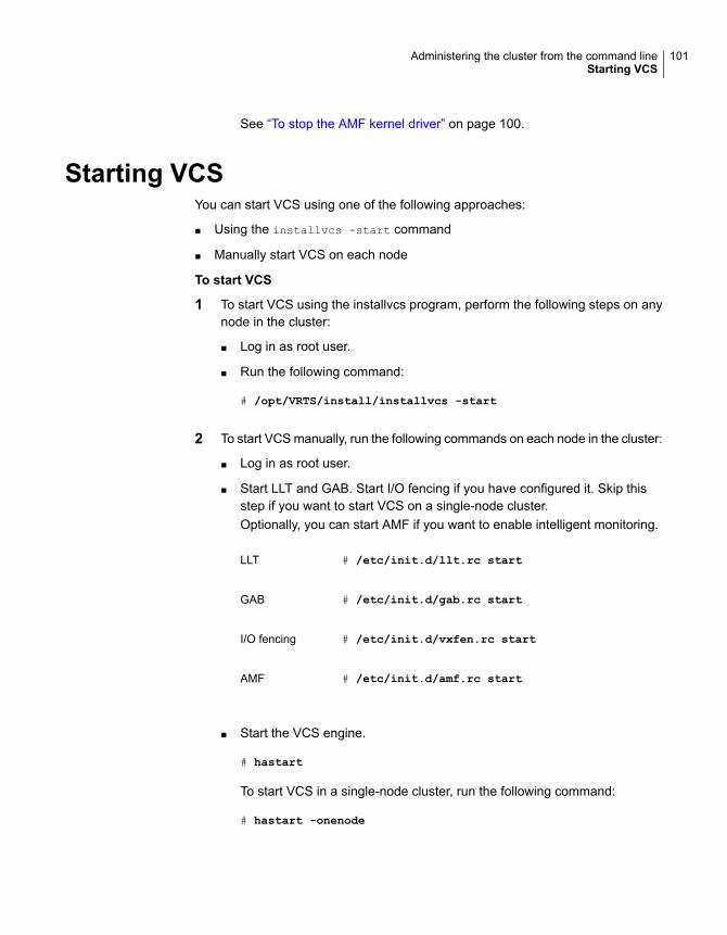
See “To stop the AMF kernel driver” on page 100.
Starting VCSYou can start VCS using one of the following approaches:
■ Using the installvcs -start command
■ Manually start VCS on each node
To start VCS
1 To start VCS using the installvcs program, perform the following steps on anynode in the cluster:
■ Log in as root user.
■ Run the following command:
# /opt/VRTS/install/installvcs -start
2 To start VCS manually, run the following commands on each node in the cluster:
■ Log in as root user.
■ Start LLT and GAB. Start I/O fencing if you have configured it. Skip thisstep if you want to start VCS on a single-node cluster.Optionally, you can start AMF if you want to enable intelligent monitoring.
# /etc/init.d/llt.rc startLLT
# /etc/init.d/gab.rc startGAB
# /etc/init.d/vxfen.rc startI/O fencing
# /etc/init.d/amf.rc startAMF
■ Start the VCS engine.
# hastart
To start VCS in a single-node cluster, run the following command:
# hastart -onenode
101Administering the cluster from the command lineStarting VCS

See “Starting the VCS engine (HAD) and related processes” on page 102.
3 Verify that the VCS cluster is up and running.
# gabconfig -a
Make sure that port a and port h memberships exist in the output for all nodesin the cluster. If you configured I/O fencing, port b membership must also exist.
Starting the VCS engine (HAD) and related processesThe command to start VCS is invoked from the following file:
/etc/init.d/vcs.rc
When VCS is started, it checks the state of its local configuration file and registerswith GAB for cluster membership. If the local configuration is valid, and if no othersystem is running VCS, it builds its state from the local configuration file and entersthe RUNNING state.
If the configuration on all nodes is invalid, the VCS engine waits for manualintervention, or for VCS to be started on a system that has a valid configuration.
See “System states” on page 651.
To start the VCS engine
◆ Run the following command:
# hastart
To start the VCS engine when all systems are in the ADMIN_WAIT state
◆ Run the following command from any system in the cluster to force VCS touse the configuration file from the system specified by the variable system:
# hasys -force system
To start VCS on a single-node cluster
◆ Type the following command to start an instance of VCS that does not requireGAB and LLT. Do not use this command on a multisystem cluster.
# hastart -onenode
Stopping VCSYou can stop VCS using one of the following approaches:
102Administering the cluster from the command lineStopping VCS

■ Using the installvcs -stop command
■ Manually stop VCS on each node
To stop VCS
1 To stop VCS using the installvcs program, perform the following steps on anynode in the cluster:
■ Log in as root user.
■ Run the following command:
# /opt/VRTS/install/installvcs -stop
2 To stop VCS manually, run the following commands on each node in the cluster:
■ Log in as root user.
■ Take the VCS service groups offline and verify that the groups are offline.
# hagrp -offline service_group -sys system
# hagrp -state service_group
■ Stop the VCS engine.
# hastop -local
See “Stopping the VCS engine and related processes” on page 104.
■ Verify that the VCS engine port h is closed.
# gabconfig -a
■ Stop I/O fencing if you have configured it. Stop GAB and then LLT.
# /etc/init.d/vxfen.rc stopI/O fencing
# /etc/init.d/gab.rc stopGAB
# /etc/init.d/llt.rc stopLLT
103Administering the cluster from the command lineStopping VCS
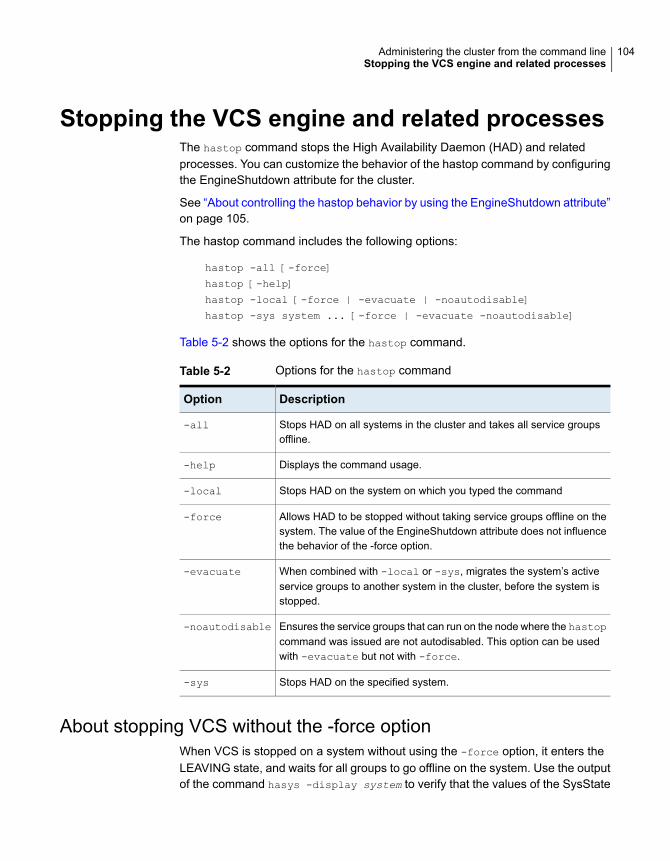
Stopping the VCS engine and related processesThe hastop command stops the High Availability Daemon (HAD) and relatedprocesses. You can customize the behavior of the hastop command by configuringthe EngineShutdown attribute for the cluster.
See “About controlling the hastop behavior by using the EngineShutdown attribute”on page 105.
The hastop command includes the following options:
hastop -all [-force]
hastop [-help]
hastop -local [-force | -evacuate | -noautodisable]
hastop -sys system ... [-force | -evacuate -noautodisable]
Table 5-2 shows the options for the hastop command.
Table 5-2 Options for the hastop command
DescriptionOption
Stops HAD on all systems in the cluster and takes all service groupsoffline.
-all
Displays the command usage.-help
Stops HAD on the system on which you typed the command-local
Allows HAD to be stopped without taking service groups offline on thesystem. The value of the EngineShutdown attribute does not influencethe behavior of the -force option.
-force
When combined with -local or -sys, migrates the system’s activeservice groups to another system in the cluster, before the system isstopped.
-evacuate
Ensures the service groups that can run on the node where the hastopcommand was issued are not autodisabled. This option can be usedwith -evacuate but not with -force.
-noautodisable
Stops HAD on the specified system.-sys
About stopping VCS without the -force optionWhen VCS is stopped on a system without using the -force option, it enters theLEAVING state, and waits for all groups to go offline on the system. Use the outputof the command hasys -display system to verify that the values of the SysState
104Administering the cluster from the command lineStopping the VCS engine and related processes

and the OnGrpCnt attributes are non-zero. VCS continues to wait for the servicegroups to go offline before it shuts down.
See “Troubleshooting resources” on page 610.
About stopping VCS with options other than the -force optionWhen VCS is stopped by options other than -force on a system with online servicegroups, the groups that run on the system are taken offline and remain offline. VCSindicates this by setting the attribute IntentOnline to 0. Use the option -force toenable service groups to continue being online while the VCS engine (HAD) isbrought down and restarted. The value of the IntentOnline attribute remainsunchanged after the VCS engine restarts.
About controlling the hastop behavior by using the EngineShutdownattribute
Use the EngineShutdown attribute to define VCS behavior when a user runs thehastop command.
Note: VCS does not consider this attribute when the hastop is issued with thefollowing options: -force or -local -evacuate -noautodisable.
Configure one of the following values for the attribute depending on the desiredfunctionality for the hastop command:
Table 5-3 shows the engine shutdown values for the attribute.
Table 5-3 Engine shutdown values
DescriptionEngineShutdownValue
Process all hastop commands. This is the default behavior.Enable
Reject all hastop commands.Disable
Do not process the hastop -all command; process all other hastopcommands.
DisableClusStop
Prompt for user confirmation before you run the hastop -allcommand; process all other hastop commands.
PromptClusStop
Prompt for user confirmation before you run the hastop -localcommand; process all other hastop commands except hastop -syscommand.
PromptLocal
105Administering the cluster from the command lineStopping the VCS engine and related processes

Table 5-3 Engine shutdown values (continued)
DescriptionEngineShutdownValue
Prompt for user confirmation before you run any hastop command.PromptAlways
Additional considerations for stopping VCSFollowing are some additional considerations for stopping VCS:
■ If you use the command reboot, behavior is controlled by the ShutdownTimeOutparameter. After HAD exits, if GAB exits within the time designated in theShutdownTimeout attribute, the remaining systems recognize this as a rebootand fail over service groups from the departed system. For systems that runseveral applications, consider increasing the value of the ShutdownTimeoutattribute.
■ If you stop VCS on a system by using the hastop command, it autodisableseach service group that includes the system in their SystemList attribute. VCSdoes not initiate online of the servicegroup when in an autodisable state. (Thisdoes not apply to systems that are powered off)
■ If you use the -evacuate option, evacuation occurs before VCS is brought down.But when there are dependencies between the service groups while -evacuate
command is issued, VCS rejects the command
Logging on to VCSVCS prompts for user name and password information when non-root users runhaxxx commands. Use the halogin command to save the authentication informationso that you do not have to enter your credentials every time you run a VCScommand. Note that you may need specific privileges to run VCS commands.
When you run the halogin command, VCS stores encrypted authenticationinformation in the user’s home directory. For clusters that run in secure mode, thecommand also sets up a trust relationship and retrieves a certificate from anauthentication broker.
If you run the command for different hosts, VCS stores authentication informationfor each host. After you run the command, VCS stores the information until you endthe session.
For clusters that run in secure mode, you also can generate credentials for VCS tostore the information for 24 hours or for eight years and thus configure VCS to notprompt for passwords when you run VCS commands as non-root users.
106Administering the cluster from the command lineLogging on to VCS

See “Running high availability commands (HA) commands as non-root users onclusters in secure mode” on page 108.
Root users do not need to run halogin when running VCS commands from thelocal host.
To log on to a cluster running in secure mode
1 Set the following environment variables:
■ VCS_DOMAIN—Name of the Security domain to which the user belongs.
■ VCS_DOMAINTYPE—Type of VxSS domain: unixpwd, nt, ldap, nis, nisplus,or vx.
2 Define the node on which the VCS commands will be run. Set the VCS_HOSTenvironment variable to the name of the node. To run commands in a remotecluster, you set the variable to the virtual IP address that was configured in theClusterService group.
3 Log on to VCS:
# halogin vcsusername password
To log on to a cluster not running in secure mode
1 Define the node on which the VCS commands will be run. Set the VCS_HOSTenvironment variable to the name of the node on which to run commands. Torun commands in a remote cluster, you can set the variable to the virtual IPaddress that was configured in the ClusterService group.
2 Log on to VCS:
# halogin vcsusername password
To end a session for a host
◆ Run the following command:
# halogin -endsession hostname
To end all sessions
◆ Run the following command:
# halogin -endallsessions
After you end a session, VCS prompts you for credentials every time you runa VCS command.
107Administering the cluster from the command lineLogging on to VCS

Running high availability commands (HA) commands as non-rootusers on clusters in secure mode
Perform the following procedure to configure VCS to not prompt for passwordswhen a non-root user runs HA commands on a cluster which runs in secure mode.
To run HA commands as non-root users on clusters in secure mode
When a non-root user logs in, the logged in user context is used for HA commands,and no password is prompted. For example, if user sam has logged in to the [email protected], and if VCS configuration specifies [email protected] as thegroup administrator for group G1, then the non-root user gets administrativeprivileges for group G1.
◆ Run any HA command. This step generates credentials for VCS to store theauthentication information. For example, run the following command:
# hasys -state
About managing VCS configuration filesThis section describes how to verify, back up, and restore VCS configuration files.
See “About the main.cf file” on page 60.
See “About the types.cf file” on page 64.
About multiple versions of .cf filesWhen hacf creates a .cf file, it does not overwrite existing .cf files. A copy of the fileremains in the directory, and its name includes a suffix of the date and time it wascreated, such as main.cf.03Dec2001.17.59.04. In addition, the previous version ofany .cf file is saved with the suffix .previous; for example, main.cf.previous.
Verifying a configurationUse hacf to verify (check syntax of) the main.cf and the type definition file, types.cf.VCS does not run if hacf detects errors in the configuration.
108Administering the cluster from the command lineAbout managing VCS configuration files

To verify a configuration
◆ Run the following command:
# hacf -verify config_directory
The variable config_directory refers to directories containing a main.cf file andany .cf files included in main.cf.
No error message and a return value of zero indicates that the syntax is legal.
Scheduling automatic backups for VCS configuration filesConfigure the BackupInterval attribute to instruct VCS to create a back up of theconfiguration periodically. VCS backs up the main.cf and types.cf files asmain.cf.autobackup and types.cf.autobackup, respectively.
To start periodic backups of VCS configuration files
◆ Set the cluster-level attribute BackupInterval to a non-zero value.
For example, to back up the configuration every 5 minutes, set BackupIntervalto 5.
Example:
# haclus -display | grep BackupInterval
BackupInterval 0
# haconf -makerw
# haclus -modify BackupInterval 5
# haconf -dump -makero
Saving a configurationWhen you save a configuration, VCS renames the file main.cf.autobackup to main.cf.VCS also save your running configuration to the file main.cf.autobackup.
If have not configured the BackupInterval attribute, VCS saves the runningconfiguration.
See “Scheduling automatic backups for VCS configuration files” on page 109.
109Administering the cluster from the command lineAbout managing VCS configuration files

To save a configuration
◆ Run the following command
# haconf -dump -makero
The option -makero sets the configuration to read-only.
Setting the configuration to read or writeThis topic describes how to set the configuration to read/write.
To set the mode to read or write
◆ Type the following command:
# haconf -makerw
Displaying configuration files in the correct formatWhen you manually edit VCS configuration files (for example, the main.cf or types.cffile), you create formatting issues that prevent the files from being parsed correctly.
To display the configuration files in the correct format
◆ Run the following commands to display the configuration files in the correctformat:
# hacf -cftocmd config
# hacf -cmdtocf config
About managing VCS users from the commandline
You can add, modify, and delete users on any system in the cluster, provided youhave the privileges to do so.
If VCS is running in secure mode, specify user names, in one of the followingformats:
■ username@domain
■ username
Specify only the user name to assign cluster-level privileges to a user. The usercan access any node in the cluster. Privileges for a cluster-level user are the sameacross nodes in the cluster.
110Administering the cluster from the command lineAbout managing VCS users from the command line

Specify the user name and the domain name to add a user on multiple nodes inthe cluster. This option requires multiple entries for a user, one for each node.
You cannot assign or change passwords for users when VCS is running in securemode.
The commands to add, modify, and delete a user must be executed only as rootor administrator and only if the VCS configuration is in read/write mode.
See “Setting the configuration to read or write” on page 110.
Note: You must add users to the VCS configuration to monitor and administer VCSfrom the graphical user interface Cluster Manager.
Adding a userUsers in the category Cluster Guest cannot add users.
To add a user
1 Set the configuration to read/write mode:
# haconf -makerw
2 Add the user:
# hauser -add user [-priv <Administrator|Operator> [-group
service_groups]]
3 Enter a password when prompted.
4 Reset the configuration to read-only:
# haconf -dump -makero
To add a user with cluster administrator access
◆ Type the following command:
# hauser -add user -priv Administrator
To add a user with cluster operator access
◆ Type the following command:
# hauser -add user -priv Operator
111Administering the cluster from the command lineAbout managing VCS users from the command line

To add a user with group administrator access
◆ Type the following command:
# hauser -add user -priv Administrator -group service_groups
To add a user with group operator access
◆ Type the following command:
# hauser -add user -priv Operator -group service_groups
To add a user on only one node with cluster administrator access
1 Set the configuration to read/write mode:
# haconf -makerw
2 Add the user:
# hauser -add [email protected] -priv Administrator
For example,
# hauser -add [email protected] -priv Administrator
3 Reset the configuration to read-only:
# haconf -dump -makero
To add a user on only one node with group administrator access
◆ Type the following command:
# hauser -add [email protected] -priv Administrator -group service_groups
Assigning and removing user privilegesThe following procedure desribes how to assign and remove user privileges:
To assign privileges to an administrator or operator
◆ Type the following command:
hauser -addpriv user Adminstrator|Operator
[-group service_groups]
112Administering the cluster from the command lineAbout managing VCS users from the command line

To remove privileges from an administrator or operator
◆ Type the following command:
hauser -delpriv user Adminstrator|Operator
[-group service_groups]
To assign privileges to an OS user group
◆ Type the following command:
hauser -addpriv usergroup AdminstratorGroup|OperatorGroup
[-group service_groups]
To remove privileges from an OS user group
◆ Type the following command:
hauser -delpriv usergroup AdminstratorGroup|OperatorGroup
[-group service_groups]
Modifying a userUsers in the category Cluster Guest cannot modify users.
You cannot modify a VCS user in clusters that run in secure mode.
To modify a user
1 Set the configuration to read or write mode:
# haconf -makerw
2 Enter the following command to modify the user:
# hauser -update user
3 Enter a new password when prompted.
4 Reset the configuration to read-only:
# haconf -dump -makero
Deleting a userYou can delete a user from the VCS configuration.
113Administering the cluster from the command lineAbout managing VCS users from the command line

To delete a user
1 Set the configuration to read or write mode:
# haconf -makerw
2 For users with Administrator and Operator access, remove their privileges:
# hauser -delpriv user Adminstrator|Operator [-group
service_groups]
3 Delete the user from the list of registered users:
# hauser -delete user
4 Reset the configuration to read-only:
# haconf -dump -makero
Displaying a userThis topic describes how to display a list of users and their privileges.
To display a list of users
◆ Type the following command:
# hauser -list
To display the privileges of all users
◆ Type the following command:
# hauser -display
To display the privileges of a specific user
◆ Type the following command:
# hauser -display user
About querying VCSVCS enables you to query various cluster objects, including resources, servicegroups, systems, resource types, agents, clusters, and sites. You may executecommands from any system in the cluster. Commands to display information on
114Administering the cluster from the command lineAbout querying VCS

the VCS configuration or system states can be executed by all users: you do notneed root privileges.
Querying service groupsThis topic describes how to perform a query on service groups.
To display the state of a service group on a system
◆ Type the following command:
# hagrp -state [service_group] [-sys system]
To display the resources for a service group
◆ Type the following command:
# hagrp -resources service_group
To display a list of a service group’s dependencies
◆ Type the following command:
# hagrp -dep [service_group]
To display a service group on a system
◆ Type the following command:
# hagrp -display [service_group] [-sys system]
If service_group is not specified, information regarding all service groups isdisplayed.
To display the attributes of a system
◆ Type the following command:
# hagrp -display [service_group]
[-attribute attribute] [-sys system]
Note that system names are case-sensitive.
To display the value of a service group attribute
◆ Type the following command:
# hagrp -value service_group attribute
115Administering the cluster from the command lineAbout querying VCS

To forecast the target system for failover
◆ Use the following command to view the target system to which a service groupfails over during a fault:
# hagrp -forecast service_group [-policy failoverpolicy value] [-verbose]
The policy values can be any one of the following values: Priority, RoundRobin,Load or BiggestAvailable.
Note: You cannot use the -forecast option when the service group state isin transition. For example, VCS rejects the command if the service group is intransition to an online state or to an offline state.
The -forecast option is supported only for failover service groups. In case ofoffline failover service groups, VCS selects the target system based on theservice group’s failover policy.
The BiggestAvailable policy is applicable only when the service group attributeLoad is defined and cluster attribute Statistics is enabled.
The actual service group FailOverPolicy can be configured as any policy, butthe forecast is done as though FailOverPolicy is set to BiggestAvailable.
Querying resourcesThis topic describes how to perform a query on resources.
To display a resource’s dependencies
◆ Enter the following command:
# hares -dep resource
Note: If you use this command to query atleast resource dependency, thedependency is displayed as a normal 1-to-1 dependency.
To display information about a resource
◆ Enter the following command:
# hares -display resource
If resource is not specified, information regarding all resources is displayed.
116Administering the cluster from the command lineAbout querying VCS

To display resources of a service group
◆ Enter the following command:
# hares -display -group service_group
To display resources of a resource type
◆ Enter the following command:
# hares -display -type resource_type
To display resources on a system
◆ Enter the following command:
# hares -display -sys system
To display the value of a specific resource attribute
◆ Enter the following command:
# hares -value resource attribute
To display atleast resource dependency
◆ Enter the following command:
# hares -dep -atleast resource
The following is an example of the command output:
#hares -dep -atleast
#Group Parent Child
g1 res1 res2,res3,res5,res6 min=2
g1 res7 res8
Querying resource typesThis topic describes how to perform a query on resource types.
To display all resource types
◆ Type the following command:
# hatype -list
117Administering the cluster from the command lineAbout querying VCS

To display resources of a particular resource type
◆ Type the following command:
# hatype -resources resource_type
To display information about a resource type
◆ Type the following command:
# hatype -display resource_type
If resource_type is not specified, information regarding all types is displayed.
To display the value of a specific resource type attribute
◆ Type the following command:
# hatype -value resource_type attribute
Querying agentsTable 5-4 lists the run-time status for the agents that the haagent -display
command displays.
Table 5-4 Run-time status for the agents
DefinitionRun-time status
Indicates the number of agent faults within one hour of the time thefault began and the time the faults began.
Faults
Displays various messages regarding agent status.Messages
Indicates the agent is operating.Running
Indicates the file is executed by the VCS engine (HAD).Started
To display the run-time status of an agent
◆ Type the following command:
# haagent -display [agent]
If agent is not specified, information regarding all agents appears.
To display the value of a specific agent attribute
◆ Type the following command:
# haagent -value agent attribute
118Administering the cluster from the command lineAbout querying VCS

Querying systemsThis topic describes how to perform a query on systems.
To display a list of systems in the cluster
◆ Type the following command:
# hasys -list
To display information about each system
◆ Type the following command:
# hasys -display [system]
If you do not specify a system, the command displays attribute names andvalues for all systems.
To display the value of a specific system attribute
◆ Type the following command:
# hasys -value system attribute
To display system attributes related to resource utilization
◆ Use the following command to view the resource utilization of the followingsystem attributes:
■ Capacity
■ HostAvailableForecast
■ HostUtilization
# hasys -util system
The -util option is applicable only if you set the cluster attribute Statistics toEnabled and define at least one key in the cluster attribute HostMeters.
The command also indicates if the HostUtilization, and HostAvailableForecastvalues are stale.
Querying clustersThis topic describes how to perform a query on clusters.
119Administering the cluster from the command lineAbout querying VCS

To display the value of a specific cluster attribute
◆ Type the following command:
# haclus -value attribute
To display information about the cluster
◆ Type the following command:
# haclus -display
Querying statusThis topic describes how to perform a query on status of service groups in thecluster.
Note:Run the hastatus command with the -summary option to prevent an incessantoutput of online state transitions. If the command is used without the option, it willrepeatedly display online state transitions until it is interrupted by the commandCTRL+C.
To display the status of all service groups in the cluster, including resources
◆ Type the following command:
# hastatus
To display the status of a particular service group, including its resources
◆ Type the following command:
# hastatus [-sound] [-time] -group service_group
[-group service_group]...
If you do not specify a service group, the status of all service groups appears.The -sound option enables a bell to ring each time a resource faults.
The -time option prints the system time at which the status was received.
To display the status of service groups and resources on specific systems
◆ Type the following command:
# hastatus [-sound] [-time] -sys system_name
[-sys system_name]...
120Administering the cluster from the command lineAbout querying VCS

To display the status of specific resources
◆ Type the following command:
# hastatus [-sound] [-time] -resource resource_name
[-resource resource_name]...
To display the status of cluster faults, including faulted service groups,resources, systems, links, and agents
◆ Type the following command:
# hastatus -summary
Querying log data files (LDFs)Log data files (LDFs) contain data regarding messages written to a correspondingEnglish language file. Typically, for each English file there is a corresponding LDF.
To display the hamsg usage list
◆ Type the following command:
# hamsg -help
To display the list of LDFs available on the current system
◆ Type the following command:
# hamsg -list
To display general LDF data
◆ Type the following command:
# hamsg -info [-path path_name] LDF
The option -path specifies where hamsg looks for the specified LDF. If notspecified, hamsg looks for files in the default directory:
/var/VRTSvcs/ldf
To display specific LDF data
◆ Type the following command:
# hamsg [-any] [-sev C|E|W|N|I]
[-otype VCS|RES|GRP|SYS|AGT]
121Administering the cluster from the command lineAbout querying VCS

[-oname object_name] [-cat category] [-msgid message_ID]
[-path path_name] [-lang language] LDF_file
Specifies hamsg return messages that match any of the specifiedquery options.
-any
Specifies hamsg return messages that match the specifiedmessage severity Critical, Error, Warning, Notice, or Information.
-sev
Specifies hamsg return messages that match the specified objecttype
■ VCS = general VCS messages■ RES = resource■ GRP = service group■ SYS = system■ AGT = agent
-otype
Specifies hamsg return messages that match the specified objectname.
-oname
Specifies hamsg return messages that match the specifiedcategory. For example, the value 2 in the message id“V-16-2-13067”
-cat
Specifies hamsg return messages that match the specifiedmessage ID. For example, the value 13067 the message id“V-16-2-13067”'
-msgid
Specifies where hamsg looks for the specified LDF. If not specified,hamsg looks for files in the default directory:
/var/VRTSvcs/ldf
-path
Specifies the language in which to display messages. For example,the value en specifies English and "ja" specifies Japanese.
-lang
Using conditional statements to query VCS objectsSome query commands include an option for conditional statements. Conditionalstatements take three forms:
Attribute=Value (the attribute equals the value)
Attribute!=Value (the attribute does not equal the value)
122Administering the cluster from the command lineAbout querying VCS

Attribute=~Value (the value is the prefix of the attribute, for example a query forthe state of a resource = ~FAULTED returns all resources whose state begins withFAULTED.)
Multiple conditional statements can be used and imply AND logic.
You can only query attribute-value pairs that appear in the output of the commandhagrp -display.
See “Querying service groups” on page 115.
To display the list of service groups whose values match a conditionalstatement
◆ Type the following command:
# hagrp -list [conditional_statement]
If no conditional statement is specified, all service groups in the cluster arelisted.
To display a list of resources whose values match a conditional statement
◆ Type the following command:
# hares -list [conditional_statement]
If no conditional statement is specified, all resources in the cluster are listed.
To display a list of agents whose values match a conditional statement
◆ Type the following command:
# haagent -list [conditional_statement]
If no conditional statement is specified, all agents in the cluster are listed.
About administering service groupsAdministration of service groups includes tasks such as adding, deleting, ormodifying service groups.
Adding and deleting service groupsThis topic describes how to add or delete a service group.
123Administering the cluster from the command lineAbout administering service groups

To add a service group to your cluster
◆ Type the following command:
# hagrp -add service_group
The variable service_group must be unique among all service groups definedin the cluster.
This command initializes a service group that is ready to contain variousresources. To employ the group properly, you must populate its SystemListattribute to define the systems on which the group may be brought online andtaken offline. (A system list is an association of names and integers thatrepresent priority values.)
To delete a service group
◆ Type the following command:
# hagrp -delete service_group
Note that you cannot delete a service group until all of its resources are deleted.
Modifying service group attributesThis topic describes how to modify service group attributes.
124Administering the cluster from the command lineAbout administering service groups

To modify a service group attribute
◆ Type the following command:
# hagrp -modify service_group attribute value [-sys system]
The variable value represents:
system_name1 priority1 system_name2 priority2
If the attribute that is being modified has local scope, you must specify thesystem on which to modify the attribute, except when modifying the attributeon the system from which you run the command.
For example, to populate the system list of service group groupx with SystemsA and B, type:
# hagrp -modify groupx SystemList -add SystemA 1 SystemB 2
Similarly, to populate the AutoStartList attribute of a service group, type:
# hagrp -modify groupx AutoStartList SystemA SystemB
You may also define a service group as parallel. To set the Parallel attributeto 1, type the following command. (Note that the default for this attribute is 0,which designates the service group as a failover group.):
# hagrp -modify groupx Parallel 1
You cannot modify this attribute if resources have already been added to theservice group.
You can modify the attributes SystemList, AutoStartList, and Parallel only byusing the command hagrp -modify. You cannot modify attributes created bythe system, such as the state of the service group.
Modifying the SystemList attributeYou use the hagrp -modify command to change a service group’s existing systemlist, you can use the options -modify, -add, -update, -delete, or -delete -keys.
For example, suppose you originally defined the SystemList of service group groupxas SystemA and SystemB. Then after the cluster was brought up you added a newsystem to the list:
# hagrp -modify groupx SystemList -add SystemC 3
You must take the service group offline on the system that is being modified.
125Administering the cluster from the command lineAbout administering service groups

When you add a system to a service group’s system list, the system must havebeen previously added to the cluster. When you use the command line, you canuse the hasys -add command.
When you delete a system from a service group’s system list, the service groupmust not be online on the system to be deleted.
If you attempt to change a service group’s existing system list by using hagrp
-modify without other options (such as -add or -update) the command fails.
Bringing service groups onlineThis topic describes how to bring service groups online.
To bring a service group online
◆ Type one of the following commands:
# hagrp -online service_group -sys system
# hagrp -online service_group -site [site_name]
To start a service group on a system and bring online only the resourcesalready online on another system
◆ Type the following command:
# hagrp -online service_group -sys system
-checkpartial other_system
If the service group does not have resources online on the other system, theservice group is brought online on the original system and the checkpartial
option is ignored.
Note that the checkpartial option is used by the Preonline trigger duringfailover. When a service group that is configured with Preonline =1 fails overto another system (system 2), the only resources brought online on system 2are those that were previously online on system 1 prior to failover.
To bring a service group and its associated child service groups online
◆ Type one of the following commands:
■ # hagrp -online -propagate service_group -sys system
■ # hagrp -online -propagate service_group -any
■ # hagrp -online -propagate service_group -site site
126Administering the cluster from the command lineAbout administering service groups

Note: See the man pages associated with the hagrp command for more informationabout the -propagate option.
Taking service groups offlineThis topic describes how to take service groups offline.
To take a service group offline
◆ Type one of the following commands:
# hagrp -offline service_group -sys system
# hagrp -offline service_group -site site_name
To take a service group offline only if all resources are probed on the system
◆ Type the following command:
# hagrp -offline [-ifprobed] service_group -sys system
To take a service group and its associated parent service groups offline
◆ Type one of the following commands:
■ # hagrp -offline -propagate service_group -sys system
■ # hagrp -offline -propagate service_group -any
■ # hagrp -offline -propagate service_group -site site_name
Note: See the man pages associated with the hagrp command for more informationabout the -propagate option.
Switching service groupsThe process of switching a service group involves taking it offline on its currentsystem or site and bringing it online on another system or site.
127Administering the cluster from the command lineAbout administering service groups

To switch a service group from one system to another
◆ Type the following command:
# hagrp -switch service_group -to system
# hagrp -switch service_group -site site_name
A service group can be switched only if it is fully or partially online. The -switch
option is not supported for switching hybrid service groups across systemzones.
Switch parallel global groups across clusters by using the following command:
# hagrp -switch service_group -any -clus remote_cluster
VCS brings the parallel service group online on all possible nodes in the remotecluster.
Migrating service groupsVCS provides live migration capabilities for service groups that have resources tomonitor virtual machines. The process of migrating a service group involvesconcurrently moving the service group from the source system to the target systemwith minimum downtime.
To migrate a service group from one system to another
◆ Type the following command:
# hagrp -migrate service_group -to system
A service group can be migrated only if it is fully online. The -migrate optionis supported only for failover service groups and for resource types that havethe SupportedOperations attribute set to migrate.
See “Resource type attributes” on page 664.
The service group must meet the following requirements regarding configuration:
■ A single mandatory resource that can be migrated, having theSupportedOperations attribute set to migrate and the Operations attribute setto OnOff
■ Other optional resources with Operations attribute set to None or OnOnly
The -migrate option is supported for the following configurations:
■ Stand alone service groups
■ Service groups having one or both of the following configurations:
128Administering the cluster from the command lineAbout administering service groups

Parallel child service groups with online local soft or online local firmdependencies
■
■ Parallel or failover parent service group with online global soft or onlineremote soft dependencies
Freezing and unfreezing service groupsFreeze a service group to prevent it from failing over to another system. This freezingprocess stops all online and offline procedures on the service group.
Note that if the service group is in ONLINE state and if you freeze the service group,then the group continues to remain in ONLINE state.
Unfreeze a frozen service group to perform online or offline operations on the servicegroup.
To freeze a service group (disable online, offline, and failover operations)
◆ Type the following command:
# hagrp -freeze service_group [-persistent]
The option -persistent enables the freeze to be remembered when the clusteris rebooted.
To unfreeze a service group (reenable online, offline, and failover operations)
◆ Type the following command:
# hagrp -unfreeze service_group [-persistent]
Enabling and disabling service groupsEnable a service group before you bring it online. A service group that was manuallydisabled during a maintenance procedure on a system may need to be broughtonline after the procedure is completed.
Disable a service group to prevent it from coming online. This process temporarilystops VCS from monitoring a service group on a system that is undergoingmaintenance operations
To enable a service group
◆ Type the following command:
# hagrp -enable service_group [-sys system]
A group can be brought online only if it is enabled.
129Administering the cluster from the command lineAbout administering service groups

To disable a service group
◆ Type the following command:
# hagrp -disable service_group [-sys system]
A group cannot be brought online or switched if it is disabled.
To enable all resources in a service group
◆ Type the following command:
# hagrp -enableresources service_group
To disable all resources in a service group
◆ Type the following command:
# hagrp -disableresources service_group
Agents do not monitor group resources if resources are disabled.
Enabling and disabling priority based failover for a service groupThis topic describes how to enable and disable priority based failover for a servicegroup. Even though the priority based failover gets configured for all the servicegroups in a cluster, you must enable the feature at the cluster level.
To enable priority based failover of your service group
■ Run the following command on the cluster:
# haclus -modify EnablePBF 1
This attribute enables Priority based failover for high priority service group.During a failover, VCS checks the load requirement for the high-priority servicegroup and evaluates the best available target that meets the load requirement.If none of the available systems meet the load requirement, then VCS checksfor any lower priority groups that can be offlined to meet the load requirement.
VCS performs the following checks, before failing over the high-priority servicegroup:
■ Check the best target system that meets the load requirement of the high-priorityservice group.
■ If no system meets the load requirement, create evacuation plan for each targetsystem to see which system will have the minimum disruption.
■ Evacuation plan consists of a list of low priority service groups that need to betaken offline to meet the load requirement. Disruption factor is calculated for the
130Administering the cluster from the command lineAbout administering service groups

system along with the evacuation plan. Disruption factor is based on the priorityof the service groups that will be brought offline or evacuated. The followingtable shows the mapping of service group priority with the disruption factor:
Disruption factorService group priority
14
103
1002
Will not be evacuated1
■ Choose the System with minimum disruption as the target system and executeevacuation plan. This initiates the offline of the low priority service groups. Planis visible under attribute ( Group::EvacList) . After all the groups in the evacuationplan are offline, initiate online of high priority service group.
To disable priority based failover of your service group:
■ Run the following command on the service group:
# haclus -modify EnablePBF 0
Note: This attribute cannot be modified when evacuation of a group is inprogress.
Clearing faulted resources in a service groupClear a resource to remove a fault and make the resource available to go online.
To clear faulted, non-persistent resources in a service group
◆ Type the following command:
# hagrp -clear service_group [-sys system]
Clearing a resource initiates the online process previously blocked while waitingfor the resource to become clear.
■ If system is specified, all faulted, non-persistent resources are cleared fromthat system only.
■ If system is not specified, the service group is cleared on all systems in thegroup’s SystemList in which at least one non-persistent resource has faulted.
131Administering the cluster from the command lineAbout administering service groups
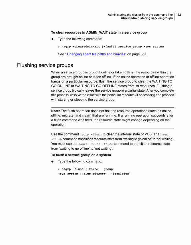
To clear resources in ADMIN_WAIT state in a service group
◆ Type the following command:
# hagrp -clearadminwait [-fault] service_group -sys system
See “ Changing agent file paths and binaries” on page 357.
Flushing service groupsWhen a service group is brought online or taken offline, the resources within thegroup are brought online or taken offline. If the online operation or offline operationhangs on a particular resource, flush the service group to clear the WAITING TOGO ONLINE or WAITING TO GO OFFLINE states from its resources. Flushing aservice group typically leaves the service group in a partial state. After you completethis process, resolve the issue with the particular resource (if necessary) and proceedwith starting or stopping the service group.
Note: The flush operation does not halt the resource operations (such as online,offline, migrate, and clean) that are running. If a running operation succeeds aftera flush command was fired, the resource state might change depending on theoperation.
Use the command hagrp -flush to clear the internal state of VCS. The hagrp
-flush command transitions resource state from ‘waiting to go online’ to ‘not waiting’.You must use the hagrp -flush -force command to transition resource statefrom ‘waiting to go offline’ to ‘not waiting’.
To flush a service group on a system
◆ Type the following command:
# hagrp -flush [-force] group
-sys system [-clus cluster | -localclus]
132Administering the cluster from the command lineAbout administering service groups

To flush all service groups on a system
1 Save the following script as haflush at the location /opt/VRTSvcs/bin/
#!/bin/ksh
PATH=/opt/VRTSvcs/bin:$PATH; export PATH
if [ $# -ne 1 ]; then
echo "usage: $0 <system name>"
exit 1
fi
hagrp -list |
while read grp sys junk
do
locsys="${sys##*:}"
case "$locsys" in
"$1")
hagrp -flush "$grp" -sys "$locsys"
;;
esac
done
2 Run the script.
# haflush systemname
Linking and unlinking service groupsThis topic describes how to link service groups to create a dependency betweenthem.
See “About service group dependencies” on page 381.
133Administering the cluster from the command lineAbout administering service groups

To link service groups
◆ Type the following command
# hagrp -link parent_group child_group
gd_category gd_location [gd_type]
Name of the parent groupparent_group
Name of the child groupchild_group
Category of group dependency (online/offline).gd_category
The scope of dependency (local/global/remote/site).gd_location
Type of group dependency (soft/firm/hard). Default is firm.gd_type
To unlink service groups
◆ Type the following command:
# hagrp -unlink parent_group child_group
Administering agentsUnder normal conditions, VCS agents are started and stopped automatically.
To start an agent
◆ Run the following command:
haagent -start agent -sys system
To stop an agent
◆ Run the following command:
haagent -stop agent [-force] -sys system
The -force option stops the agent even if the resources for the agent areonline. Use the -force option when you want to upgrade an agent without takingits resources offline.
134Administering the cluster from the command lineAdministering agents

About administering resourcesAdministration of resources includes tasks such as adding, deleting, modifying,linking, unlinking , probing, and clearing resources, bringing resources online, andtaking them offline.
About adding resourcesWhen you add a resource, all non-static attributes of the resource’s type, plus theirdefault values, are copied to the new resource.
Three attributes are also created by the system and added to the resource:
■ Critical (default = 1). If the resource or any of its children faults while online, theentire service group is marked faulted and failover occurs.In an atleast resource set, the fault of a critical resource is tolerated until theminimum requirement associated with the resource set is met.
■ AutoStart (default = 1). If the resource is set to AutoStart, it is brought online inresponse to a service group command. All resources designated as AutoStart=1must be online for the service group to be considered online. (This attribute isunrelated to AutoStart attributes for service groups.)
■ Enabled. If the resource is set to Enabled, the agent for the resource’s typemanages the resource. The default is 1 for resources defined in the configurationfile main.cf, 0 for resources added on the command line.
Note: The addition of resources on the command line requires several steps, andthe agent must be prevented from managing the resource until the steps arecompleted. For resources defined in the configuration file, the steps are completedbefore the agent is started.
Adding resourcesThis topic describes how to add resources to a service group or remove resourcesfrom a service group.
To add a resource
◆ Type the following command:
hares -add resource resource_type service_group
The resource name must be unique throughout the cluster. The resource typemust be defined in the configuration language. The resource belongs to thegroup service_group.
135Administering the cluster from the command lineAbout administering resources

Deleting resourcesThis topic describes how to delete resources from a service group.
To delete a resource
◆ Type the following command:
hares -delete resource
VCS does not delete online resources. However, you can enable deletion ofonline resources by changing the value of the DeleteOnlineResources attribute.
See “Cluster attributes” on page 722.
To delete a resource forcibly, use the -force option, which takes the resoureoffline irrespective of the value of the DeleteOnlineResources attribute.
hares -delete -force resource
Adding, deleting, and modifying resource attributesResource names must be unique throughout the cluster and you cannot modifyresource attributes defined by the system, such as the resource state.
To modify a new resource
◆ Type the following command:
hares -modify resource attribute value
hares -modify resource attribute value
[-sys system] [-wait [-time waittime]]
The variable value depends on the type of attribute being created.
To set a new resource’s Enabled attribute to 1
◆ Type the following command:
hares -modify resourceA Enabled 1
The agent managing the resource is started on a system when its Enabledattribute is set to 1 on that system. Specifically, the VCS engine begins tomonitor the resource for faults. Agent monitoring is disabled if the Enabledattribute is reset to 0.
136Administering the cluster from the command lineAbout administering resources

To add a resource attribute
◆ Type the following command:
haattr -add resource_type attribute
[value] [dimension] [default ...]
The variable value is a -string (default), -integer, or -boolean.
The variable dimension is -scalar (default), -keylist, -assoc, or -vector.
The variable default is the default value of the attribute and must be compatiblewith the value and dimension. Note that this may include more than one item,as indicated by ellipses (...).
To delete a resource attribute
◆ Type the following command:
haattr -delete resource_type attribute
To add a static resource attribute
◆ Type the following command:
haattr -add -static resource_type static_attribute
[value] [dimension] [default ...]
To delete a static resource attribute
◆ Type the following command:
haattr -delete -static resource_type static_attribute
To add a temporary resource attribute
◆ Type the following command:
haattr -add -temp resource_type attribute
[value] [dimension] [default ...]
To delete a temporary resource attribute
◆ Type the following command:
haattr -delete -temp resource_type attribute
137Administering the cluster from the command lineAbout administering resources

To modify the default value of a resource attribute
◆ Type the following command:
haattr -default resource_type attribute new_value ...
The variable new_value refers to the attribute’s new default value.
Defining attributes as localLocalizing an attribute means that the attribute has a per-system value for eachsystem listed in the group’s SystemList. These attributes are localized on aper-resource basis. For example, to localize the attribute attribute_name for resourceonly, type:
hares -local resource attribute_name
Note that global attributes cannot be modified with the hares -local command.
Table 5-5 lists the commands to be used to localize attributes depending on theirdimension.
Table 5-5 Making VCS attributes local
Task and CommandDimension
Replace a value:
-modify [object] attribute_name value [-sys system]
scalar
■ Replace list of values:-modify [object] attribute_name value [-sys system]
■ Add list of values to existing list:-modify [object] attribute_name -add value [-syssystem]
■ Update list with user-supplied values:-modify [object] attribute_name -update entry_value... [-sys system]
■ Delete user-supplied values in list (if the list has multiple occurrencesof the same value, then all the occurrences of the value is deleted):-modify [object] attribute_name -delete <key> ...[-sys system]
■ Delete all values in list:-modify [object] attribute_name -delete -keys [-syssystem]
vector
138Administering the cluster from the command lineAbout administering resources
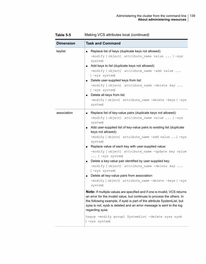
Table 5-5 Making VCS attributes local (continued)
Task and CommandDimension
■ Replace list of keys (duplicate keys not allowed):-modify [object] attribute_name value ... [-syssystem]
■ Add keys to list (duplicate keys not allowed):-modify [object] attribute_name -add value ...[-sys system]
■ Delete user-supplied keys from list:-modify [object] attribute_name -delete key ...[-sys system]
■ Delete all keys from list:-modify [object] attribute_name -delete -keys [-syssystem]
keylist
■ Replace list of key-value pairs (duplicate keys not allowed):-modify [object] attribute_name value ... [-syssystem]
■ Add user-supplied list of key-value pairs to existing list (duplicatekeys not allowed):-modify [object] attribute_name -add value ...[-syssystem]
■ Replace value of each key with user-supplied value:-modify [object] attribute_name -update key value... [-sys system]
■ Delete a key-value pair identified by user-supplied key:-modify [object] attribute_name -delete key ...[-sys system]
■ Delete all key-value pairs from association:-modify [object] attribute_name -delete -keys [-syssystem]
Note: If multiple values are specified and if one is invalid, VCS returnsan error for the invalid value, but continues to process the others. Inthe following example, if sysb is part of the attribute SystemList, butsysa is not, sysb is deleted and an error message is sent to the logregarding sysa.
hagrp -modify group1 SystemList -delete sysa sysb[-sys system]
association
139Administering the cluster from the command lineAbout administering resources

Defining attributes as globalUse the hares -global command to set a cluster-wide value for an attribute.
To set an attribute’s value on all systems
◆ Type the following command:
# hares -global resource attribute
value ... | key... | {key value}...
Enabling and disabling intelligent resource monitoring for agentsmanually
Review the following procedures to enable or disable intelligent resource monitoringmanually. The intelligent resource monitoring feature is enabled by default. TheIMF resource type attribute determines whether an IMF-aware agent must performintelligent resource monitoring.
See “About resource monitoring” on page 37.
See “Resource type attributes” on page 664.
To enable intelligent resource monitoring
1 Make the VCS configuration writable.
# haconf -makerw
2 Run the following command to enable intelligent resource monitoring.
■ To enable intelligent monitoring of offline resources:
# hatype -modify resource_type IMF -update Mode 1
■ To enable intelligent monitoring of online resources:
# hatype -modify resource_type IMF -update Mode 2
■ To enable intelligent monitoring of both online and offline resources:
# hatype -modify resource_type IMF -update Mode 3
3 If required, change the values of the MonitorFreq key and the RegisterRetryLimitkey of the IMF attribute.
See the Cluster Server Bundled Agents Reference Guide for agent-specificrecommendations to set these attributes.
140Administering the cluster from the command lineAbout administering resources

4 Save the VCS configuration.
# haconf -dump -makero
5 Make sure that the AMF kernel driver is configured on all nodes in the cluster.
/etc/init.d/amf.rc status
If the AMF kernel driver is configured, the output resembles:
AMF: Module loaded and configured
Configure the AMF driver if the command output returns that the AMF driveris not loaded or not configured.
See “Administering the AMF kernel driver” on page 99.
6 Restart the agent. Run the following commands on each node.
# haagent -stop agent_name -force -sys sys_name
# haagent -start agent_name -sys sys_name
To disable intelligent resource monitoring
1 Make the VCS configuration writable.
# haconf -makerw
2 To disable intelligent resource monitoring for all the resources of a certain type,run the following command:
# hatype -modify resource_type IMF -update Mode 0
3 To disable intelligent resource monitoring for a specific resource, run thefollowing command:
# hares -override resource_name IMF
# hares -modify resource_name IMF -update Mode 0
4 Save the VCS configuration.
# haconf -dump -makero
141Administering the cluster from the command lineAbout administering resources
Note: VCS provides haimfconfig script to enable or disable the IMF functionalityfor agents. You can use the script with VCS in running or stopped state. Use thescript to enable or disable IMF for the IMF-aware bundled agents, enterprise agents,and custom agents.
See “Enabling and disabling IMF for agents by using script” on page 142.
Enabling and disabling IMF for agents by using scriptVCS provides a script to enable and disable IMF for agents and for the AMF module.You can use the script when VCS is running or when VCS is stopped. Use the scriptto enable or disable IMF for the IMF-aware bundled agents, enterprise agents, andcustom agents.
You must run the script once on each node of the cluster by using the samecommand. For example, if you enabled IMF for all IMF-aware agents on one node,you must repeat the action on the other cluster nodes too.
The following procedures describe how to enable or disable IMF for agents by usingthe script.
See “About resource monitoring” on page 37.
See “Resource type attributes” on page 664.
Enabling and disabling IMF for all IMF-aware agentsEnable or disable IMF for all IMF-aware agents as follows:
To enable IMF for all IMF-aware agents
◆ Run the following command:
haimfconfig -enable
To disable IMF for all IMF-aware agents
◆ Run the following command:
haimfconfig -disable
Note: The preceding haimfconfig commands cover all IMF-aware agents.
Enabling and disabling IMF for a set of agentsEnable or disable IMF for a set of agents as follows:
142Administering the cluster from the command lineAbout administering resources

To enable IMF for a set of agents
◆ Run the following command:
haimfconfig -enable -agent agent(s)
This command enables IMF for the specified agents. It also configures andloads the AMF module on the system if the module is not already loaded. Ifthe agent is a custom agent, the command prompts you for the Mode andMonitorFreq values if Mode value is not configured properly.
■ If VCS is running, this command might require to dump the configurationand to restart the agents. The command prompts whether you want tocontinue. If you choose Yes, it restarts the agents that are running anddumps the configuration. It also sets the Mode value (for all specified agents)and MonitorFreq value (for custom agents only) appropriately to enableIMF. For the agents that are not running, it changes the Mode value (for allspecified agents) and MonitorFreq value (for all specified custom agentsonly) so as to enable IMF for the agents when they start.
Note: The command prompts you whether you want to make theconfiguration changes persistent. If you choose No, the command exits. Ifyou choose Yes, it enables IMF and dumps the configuration by using thehaconf -dump -makero command.
■ If VCS is not running, changes to the Mode value (for all specified agents)and MonitorFreq value (for all specified custom agents only) need to bemade by modifying the VCS configuration files. Before the command makesany changes to configuration files, it prompts you for a confirmation. If youchoose Yes, it modifies the VCS configuration files. IMF gets enabled forthe specified agent when VCS starts.
Example
haimfconfig -enable -agent Mount Application
The command enables IMF for the Mount agent and the Application agent.
To disable IMF for a set of agents
◆ Run the following command:
haimfconfig -disable -agent agent(s)
This command disables IMF for specified agents by changing the Mode valueto 0 for each agent and for all resources that had overridden the Mode values.
143Administering the cluster from the command lineAbout administering resources
■ If VCS is running, the command changes the Mode value of the agents andthe overridden Mode values of all resources of these agents to 0.
Note: The command prompts you whether you want to make theconfiguration changes persistent. If you choose No, the command exits. Ifyou choose Yes, it enables IMF and dumps the configuration by using thehaconf -dump -makero command.
■ If VCS is not running, any change to the Mode value needs to be made bymodifying the VCS configuration file. Before it makes any changes toconfiguration files, the command prompts you for a confirmation. If youchoose Yes, it sets the Mode value to 0 in the configuration files.
Example
haimfconfig -disable -agent Mount Application
The command disables IMF for the Mount agent and Application agent.
Enabling and disabling AMF on a systemEnable or disable AMF as follows:
To enable AMF on a system
◆ Run the following command:
haimfconfig -enable -amf
This command sets the value of AMF_START to 1 in the AMF configuration file.It also configures and loads the AMF module on the system.
To disable AMF on a system
◆ Run the following command:
haimfconfig -disable -amf
This command unconfigures and unloads the AMF module on the system ifAMF is configured and loaded. It also sets the value of AMF_START to 0 in theAMF configuration file.
Note: AMF is not directly unconfigured by this command if the agent is registeredwith AMF. The script prompts you if you want to disable AMF for all agents forcefullybefore it unconfigures AMF.
144Administering the cluster from the command lineAbout administering resources

Viewing the configuration changes made by the scriptView a summary of the steps performed by the command as follows:
To view the changes made when the script enables IMF for an agent
◆ Run the following command:
haimfconfig -validate -enable -agent agent
To view the changes made when the script disables IMF for an agent
◆ Run the following command:
haimfconfig -validate -disable -agent agent
Note: The script also generates the $VCS_LOG/log/haimfconfig_A.log file. Thislog contains information about all the commands that the script runs. It also logsthe command outputs and the return values. The last ten logs are backed up.
Displaying the current IMF status of agentsTo display current IMF status
◆ Run the following command:
haimfconfig -display
The status of agents can be one of the following:
■ ENABLED: IMF is enabled for the agent.
■ DISABLED: IMF is disabled for the agent.
■ ENABLED|PARTIAL: IMF is partially enabled for some resources of the agent.The possible reasons are:
■ The agent has proper Mode value set at type level and improper mode valueset at resource level.
■ The agent has proper Mode value set at resource level and improper modevalue set at type level.
Examples:
If IMF is disabled for Mount agent (when Mode is set to 0) and enabled for rest ofthe installed IMF-aware agents:
haimfconfig -display
145Administering the cluster from the command lineAbout administering resources

#Agent STATUS
Application ENABLED
Mount DISABLED
Process ENABLED
DiskGroup ENABLED
WPAR ENABLED
If IMF is disabled for Mount agent (when VCS is running, agent is running and notregistered with AMF module) and enabled for rest of the installed IMF-aware agents:
haimfconfig -display
#Agent STATUS
Application ENABLED
Mount DISABLED
Process ENABLED
DiskGroup ENABLED
WPAR ENABLED
If IMF is disabled for all installed IMF-aware agents (when AMF module is notloaded):
haimfconfig -display
#Agent STATUS
Application DISABLED
Mount DISABLED
Process DISABLED
DiskGroup DISABLED
WPAR DISABLED
If IMF is partially enabled for Mount agent (Mode is set to 3 at type level and to 0at resource level for some resources) and enabled fully for rest of the installedIMF-aware agents.
haimfconfig -display
146Administering the cluster from the command lineAbout administering resources

#Agent STATUS
Application ENABLED
Mount ENABLED|PARTIAL
Process ENABLED
DiskGroup ENABLED
WPAR ENABLED
If IMF is partially enabled for Mount agent (Mode is set to 0 at type level and to 3at resource level for some resources) and enabled fully for rest of the installedIMF-aware agents:
haimfconfig -display
#Agent STATUS
Application ENABLED
Mount ENABLED|PARTIAL
Process ENABLED
DiskGroup ENABLED
WPAR ENABLED
Linking and unlinking resourcesLink resources to specify a dependency between them. A resource can have anunlimited number of parents and children. When you link resources, the parentcannot be a resource whose Operations attribute is equal to None or OnOnly.Specifically, these are resources that cannot be brought online or taken offline byan agent (None), or can only be brought online by an agent (OnOnly).
Loop cycles are automatically prohibited by the VCS engine. You cannot specify aresource link between resources of different service groups.
147Administering the cluster from the command lineAbout administering resources

To link resources
◆ Enter the following command:
hares -link parent_resource child_resource
The variable parent_resource depends on child_resource being online beforegoing online itself. Conversely, parent_resource go offline before child_resourcegoes offline.
For example, a NIC resource must be available before an IP resource can goonline, so for resources IP1 of type IP and NIC1 of type NIC, specify thedependency as:
hares -link IP1 NIC1
To unlink resources
◆ Enter the following command:
hares -unlink parent_resource child_resource
Configuring atleast resource dependencyIn an atleast resource dependency, the parent resource depends on a set of childresources. The parent resource is brought online or can remain online only if theminimum number of child resources in this resource set is online.
Enter the following command to set atleast resource dependency. This commandassumes that there are five child resources. If there are more child resources, enterthe resource names without space.
hares -link parent_resource
child_res1,child_res2,child_res3,child_res4,child_res5 -min
minimum_resources
The following is an example:
hares -link res1 res2,res3,res4,res5,res6 -min 2
In the above example, the parent resource (res1) depends on the child resources(res2, res3, res4, res5, and res6). The parent resource can be brought online onlywhen two or more resources come online and the parent resource can remain onlineonly until two or more child resources are online.
Bringing resources onlineThis topic describes how to bring a resource online.
148Administering the cluster from the command lineAbout administering resources

To bring a resource online
◆ Type the following command:
hares -online resource -sys system
Taking resources offlineThis topic describes how to take a resource offline.
To take a resource offline
◆ Type the following command:
hares -offline [-ignoreparent|parentprop] resource -sys system
The option -ignoreparent enables a resource to be taken offline even if itsparent resources in the service group are online. This option does not work iftaking the resources offline violates the group dependency.
To take a resource and its parent resources offline
◆ Type the following command:
hares -offline -parentprop resource -sys system
The command stops all parent resources in order before taking the specificresource offline.
To take a resource offline and propagate the command to its children
◆ Type the following command:
hares -offprop [-ignoreparent] resource -sys system
As in the above command, the option -ignoreparent enables a resource tobe taken offline even if its parent resources in the service group are online.This option does not work if taking the resources offline violates the groupdependency.
Probing a resourceThis topic describes how to probe a resource.
149Administering the cluster from the command lineAbout administering resources
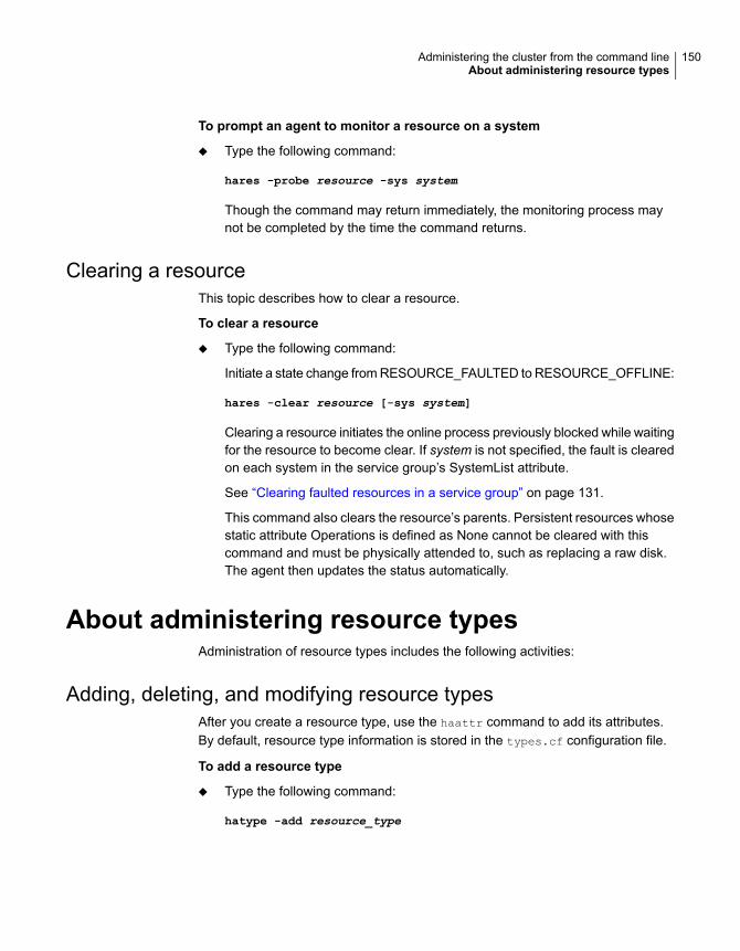
To prompt an agent to monitor a resource on a system
◆ Type the following command:
hares -probe resource -sys system
Though the command may return immediately, the monitoring process maynot be completed by the time the command returns.
Clearing a resourceThis topic describes how to clear a resource.
To clear a resource
◆ Type the following command:
Initiate a state change from RESOURCE_FAULTED to RESOURCE_OFFLINE:
hares -clear resource [-sys system]
Clearing a resource initiates the online process previously blocked while waitingfor the resource to become clear. If system is not specified, the fault is clearedon each system in the service group’s SystemList attribute.
See “Clearing faulted resources in a service group” on page 131.
This command also clears the resource’s parents. Persistent resources whosestatic attribute Operations is defined as None cannot be cleared with thiscommand and must be physically attended to, such as replacing a raw disk.The agent then updates the status automatically.
About administering resource typesAdministration of resource types includes the following activities:
Adding, deleting, and modifying resource typesAfter you create a resource type, use the haattr command to add its attributes.By default, resource type information is stored in the types.cf configuration file.
To add a resource type
◆ Type the following command:
hatype -add resource_type
150Administering the cluster from the command lineAbout administering resource types

To delete a resource type
◆ Type the following command:
hatype -delete resource_type
You must delete all resources of the type before deleting the resource type.
To add or modify resource types in main.cf without shutting down VCS
◆ Type the following command:
hatype -modify resource_type SourceFile "./resource_type.cf"
The information regarding resource_type is stored in the fileconfig/resource_type.cf.
An include line for resource_type.cf is added to the main.cf file.
Note: Make sure that the path to the SourceFile exists on all nodes before yourun this command.
To set the value of static resource type attributes
◆ Type the following command for a scalar attribute:
hatype -modify resource_type attribute value
For more information, type:
hatype -help -modify
Overriding resource type static attributesYou can override some resource type static attributes and assign themresource-specific values. When a static attribute is overriden and the configurationis saved, the main.cf file includes a line in the resource definition for the staticattribute and its overriden value.
To override a type’s static attribute
◆ Type the following command:
hares -override resource static_attribute
151Administering the cluster from the command lineAbout administering resource types

To restore default settings to a type’s static attribute
◆ Type the following command:
hares -undo_override resource static_attribute
About initializing resource type scheduling and priority attributesThe following configuration shows how to initialize resource type scheduling andpriority attributes through configuration files. The example shows attributes of aFileOnOff resource.
type FileOnOff (
static str AgentClass = RT
static str AgentPriority = 10
static str ScriptClass = RT
static str ScriptPriority = 40
static str ArgList[] = { PathName }
str PathName
)
Setting scheduling and priority attributesThis topic describes how to set scheduling and priority attributes.
Note: For attributes AgentClass and AgentPriority, changes are effectiveimmediately. For ScriptClass and ScriptPriority, changes become effective for scriptsfired after the execution of the hatype command.
To update the AgentClass
◆ Type the following command:
hatype -modify resource_type AgentClass value
For example, to set the AgentClass attribute of the FileOnOff resource toRealTime, type:
hatype -modify FileOnOff AgentClass "RT"
152Administering the cluster from the command lineAbout administering resource types

To update the AgentPriority
◆ Type the following command:
hatype -modify resource_type AgentPriority value
For example, to set the AgentPriority attribute of the FileOnOff resource to 10,type:
hatype -modify FileOnOff AgentPriority "10"
To update the ScriptClass
◆ Type the following command:
hatype -modify resource_type ScriptClass value
For example, to set the ScriptClass of the FileOnOff resource to RealTime,type:
hatype -modify FileOnOff ScriptClass "RT"
To update the ScriptPriority
◆ Type the following command:
hatype -modify resource_type ScriptPriority value
For example, to set the ScriptClass of the FileOnOff resource to 40, type:
hatype -modify FileOnOff ScriptPriority "40"
Administering systemsAdministration of systems includes tasks such as modifying system attributes,freezing or unfreezing systems, and running commands.
To modify a system’s attributes
◆ Type the following command:
hasys -modify modify_options
Some attributes are internal to VCS and cannot be modified.
See “About the -modify option” on page 88.
153Administering the cluster from the command lineAdministering systems
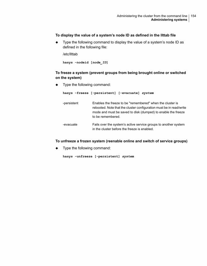
To display the value of a system’s node ID as defined in the llttab file
◆ Type the following command to display the value of a system’s node ID asdefined in the following file:
/etc/llttab
hasys -nodeid [node_ID]
To freeze a system (prevent groups from being brought online or switchedon the system)
◆ Type the following command:
hasys -freeze [-persistent] [-evacuate] system
Enables the freeze to be "remembered" when the cluster isrebooted. Note that the cluster configuration must be in read/writemode and must be saved to disk (dumped) to enable the freezeto be remembered.
-persistent
Fails over the system’s active service groups to another systemin the cluster before the freeze is enabled.
-evacuate
To unfreeze a frozen system (reenable online and switch of service groups)
◆ Type the following command:
hasys -unfreeze [-persistent] system
154Administering the cluster from the command lineAdministering systems

To run a command on any system in a cluster
◆ Type the following command:
hacli -cmd command [-sys | -server system(s)]
Issues a command to be executed on the specified system(s). VCS must berunning on the systems.
The use of the hacli command requires setting HacliUserLevel to at leastCOMMANDROOT. By default, the HacliUserLevel setting is NONE.
If the users do not want the root user on system A to enjoy root privileges onanother system B, HacliUserLevel should remain set to NONE (the default) onsystem B.
You can specify multiple systems separated by a single space as argumentsto the option -sys. If no system is specified, command runs on all systems incluster with VCS in a RUNNING state. The command argument must be enteredwithin double quotes if command includes any delimiters or options.
About administering clustersAdministration of clusters includes the following activities:
Configuring and unconfiguring the cluster UUID valueWhen you install VCS using the installer, the installer generates the cluster UUID(Universally Unique ID) value. This value is the same across all the nodes in thecluster.
You can use the uuidconfig utility to display, copy, configure, and unconfigure thecluster UUID on the cluster nodes.
Make sure you have ssh or rsh communication set up between the systems. Theutility uses ssh by default.
To display the cluster UUID value on the VCS nodes
◆ Run the following command to display the cluster UUID value:
■ For specific nodes:
# /opt/VRTSvcs/bin/uuidconfig.pl [-rsh] -clus -display sys1
[sys2 sys3...]
■ For all nodes that are specified in the /etc/llthosts file:
155Administering the cluster from the command lineAbout administering clusters
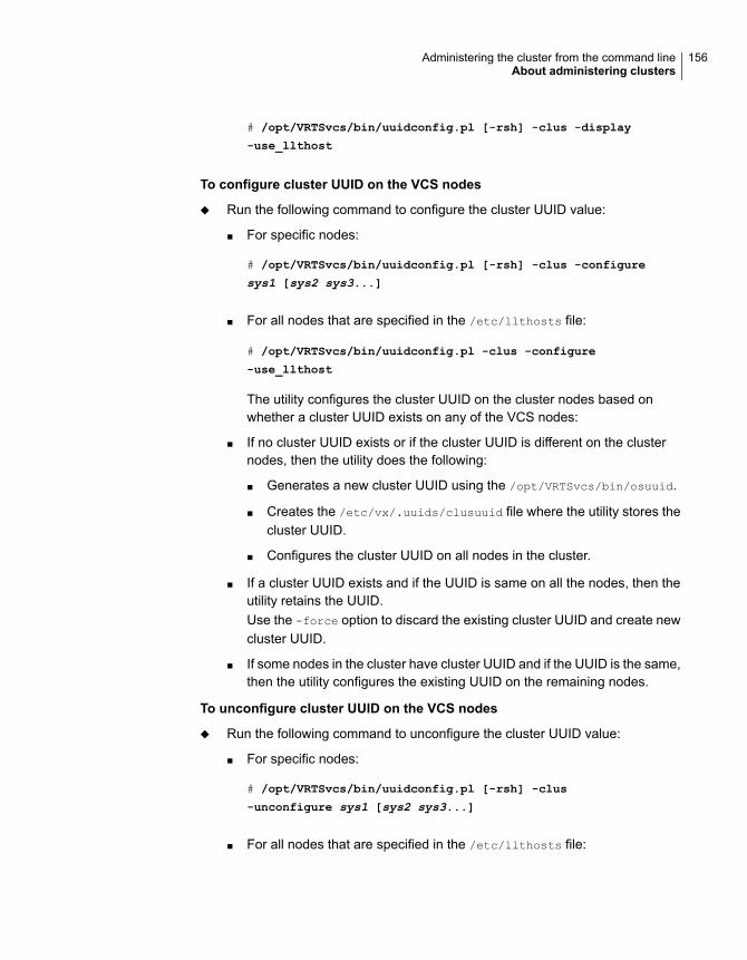
# /opt/VRTSvcs/bin/uuidconfig.pl [-rsh] -clus -display
-use_llthost
To configure cluster UUID on the VCS nodes
◆ Run the following command to configure the cluster UUID value:
■ For specific nodes:
# /opt/VRTSvcs/bin/uuidconfig.pl [-rsh] -clus -configure
sys1 [sys2 sys3...]
■ For all nodes that are specified in the /etc/llthosts file:
# /opt/VRTSvcs/bin/uuidconfig.pl -clus -configure
-use_llthost
The utility configures the cluster UUID on the cluster nodes based onwhether a cluster UUID exists on any of the VCS nodes:
■ If no cluster UUID exists or if the cluster UUID is different on the clusternodes, then the utility does the following:
■ Generates a new cluster UUID using the /opt/VRTSvcs/bin/osuuid.
■ Creates the /etc/vx/.uuids/clusuuid file where the utility stores thecluster UUID.
■ Configures the cluster UUID on all nodes in the cluster.
■ If a cluster UUID exists and if the UUID is same on all the nodes, then theutility retains the UUID.Use the -force option to discard the existing cluster UUID and create newcluster UUID.
■ If some nodes in the cluster have cluster UUID and if the UUID is the same,then the utility configures the existing UUID on the remaining nodes.
To unconfigure cluster UUID on the VCS nodes
◆ Run the following command to unconfigure the cluster UUID value:
■ For specific nodes:
# /opt/VRTSvcs/bin/uuidconfig.pl [-rsh] -clus
-unconfigure sys1 [sys2 sys3...]
■ For all nodes that are specified in the /etc/llthosts file:
156Administering the cluster from the command lineAbout administering clusters

# /opt/VRTSvcs/bin/uuidconfig.pl [-rsh] -clus
-unconfigure -use_llthost
The utility removes the /etc/vx/.uuids/clusuuid file from the nodes.
To copy the cluster UUID from one node to other nodes
◆ Run the following command to copy the cluster UUID value:
# /opt/VRTSvcs/bin/uuidconfig.pl [-rsh] -clus -copy
-from_sys sys -to_sys sys1 sys2 [sys3...]
The utility copies the cluster UUID from a system that is specified usingthe-from_sys option to all the systems that are specified using the -to_sys
option.
Retrieving version informationThis topic describes how to retrieve information about the version of VCS runningon the system.
To retrieve information about the VCS version on the system
1 Run one of the following commands to retrieve information about the engineversion, the join version, the build date, and the PSTAMP.
had -version
hastart -version
2 Run one of the following commands to retrieve information about the engineversion.
had -v
hastart -v
Adding and removing systemsThis topic provides an overview of tasks involved in adding and removing systemsfrom a cluster.
For detailed instructions, see the Cluster Server Installation Guide.
157Administering the cluster from the command lineAbout administering clusters
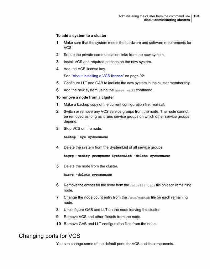
To add a system to a cluster
1 Make sure that the system meets the hardware and software requirements forVCS.
2 Set up the private communication links from the new system.
3 Install VCS and required patches on the new system.
4 Add the VCS license key.
See “About installing a VCS license” on page 92.
5 Configure LLT and GAB to include the new system in the cluster membership.
6 Add the new system using the hasys -add command.
To remove a node from a cluster
1 Make a backup copy of the current configuration file, main.cf.
2 Switch or remove any VCS service groups from the node. The node cannotbe removed as long as it runs service groups on which other service groupsdepend.
3 Stop VCS on the node.
hastop -sys systemname
4 Delete the system from the SystemList of all service groups.
hagrp -modify groupname SystemList -delete systemname
5 Delete the node from the cluster.
hasys -delete systemname
6 Remove the entries for the node from the /etc/llthosts file on each remainingnode.
7 Change the node count entry from the /etc/gabtab file on each remainingnode.
8 Unconfigure GAB and LLT on the node leaving the cluster.
9 Remove VCS and other filesets from the node.
10 Remove GAB and LLT configuration files from the node.
Changing ports for VCSYou can change some of the default ports for VCS and its components.
158Administering the cluster from the command lineAbout administering clusters

The following is a list of changes that you can make and information concerningports in a VCS environment:
■ Changing VCS's default port.Add an entry for a VCS service name In /etc/services file, for example:
vcs-app 3333/tcp # Veritas Cluster Server
Where 3333 in the example is the port number where you want to run VCS.When the engine starts, it listens on the port that you configured above (3333)for the service. You need to modify the port to the /etc/services file on all thenodes of the cluster.
■ You do not need to make changes for agents or HA commands. Agents andHA commands use locally present UDS sockets to connect to the engine, notTCP/IP connections.
■ You do not need to make changes for HA commands that you execute to talkto a remotely running VCS engine (HAD), using the facilities that the VCS_HOSTenvironment variable provides. You do not need to change these settingsbecause the HA command queries the /etc/services file and connects to theappropriate port.
■ For the Java Console GUI, you can specify the port number that you want theGUI to connect to while logging into the GUI. You have to specify the port numberthat is configured in the /etc/services file (for example 3333 above).
To change the default port
1 Stop VCS.
2 Add an entry service name vcs-app in /etc/services.
vcs-app 3333/tcp # Veritas Cluster Server
3 You need to modify the port to the /etc/services file on all the nodes of thecluster.
4 Restart VCS.
5 Check the port.
# netstat -an|grep 3333
*.3333 *.* 0 0 49152 0 LISTEN
*.3333 *.* 0 0 49152 0 LISTEN
6 Use the Java Console to connect to VCS through port 3333.
159Administering the cluster from the command lineAbout administering clusters

Setting cluster attributes from the command lineThis topic describes how to set cluster attributes from the command line.
Note: For the attributes EngineClass and EnginePriority, changes are effectiveimmediately. For ProcessClass and ProcessPriority changes become effective onlyfor processes fired after the execution of the haclus command.
To modify a cluster attribute
◆ Type the following command
# haclus [-help [-modify]]
To update the EngineClass
◆ Type the following command:
# haclus -modify EngineClass value
For example, to set the EngineClass attribute to RealTime::
# haclus -modify EngineClass "RT"
To update the EnginePriority
◆ Type the following command:
# haclus -modify EnginePriority value
For example, to set the EnginePriority to 20::
# haclus -modify EnginePriority "20"
To update the ProcessClass
◆ Type the following command:
# haclus -modify ProcessClass value
For example, to set the ProcessClass to TimeSharing:
# haclus -modify ProcessClass "TS"
160Administering the cluster from the command lineAbout administering clusters

To update the ProcessPriority
◆ Type the following command:
# haclus -modify ProcessPriority value
For example, to set the ProcessPriority to 40:
# haclus -modify ProcessPriority "40"
About initializing cluster attributes in the configuration fileYou may assign values for cluster attributes while you configure the cluster.
See “Cluster attributes” on page 722.
Review the following sample configuration:
cluster vcs-india (
EngineClass = "RT"
EnginePriority = "20"
ProcessClass = "TS"
ProcessPriority = "40"
)
Enabling and disabling secure mode for the clusterThis topic describes how to enable and disable secure mode for your cluster.
161Administering the cluster from the command lineAbout administering clusters

To enable secure mode in a VCS cluster
1 # hasys -state
The output must show the SysState value as RUNNING.
2 You can enable secure mode or secure mode with FIPS.
To enable secure mode, start the installer program with the -security option.
# /opt/VRTS/install/installer -security
To enable secure mode with FIPS, start the installer program with the-security -fips option.
# /opt/VRTS/install/installvcs -security -fips
If you already have secure mode enabled and need to move to secure modewith FIPS, complete the steps in the following procedure.
See “Migrating from secure mode to secure mode with FIPS” on page 163.
The installer displays the directory where the logs are created.
3 Review the output as the installer verifies whether VCS configuration files exist.
The installer also verifies that VCS is running on all systems in the cluster.
4 The installer checks whether the cluster is in secure mode or non-secure mode.If the cluster is in non-secure mode, the installer prompts whether you want toenable secure mode.
Do you want to enable secure mode in this cluster? [y,n,q] (y) y
5 Review the output as the installer modifies the VCS configuration files to enablesecure mode in the cluster, and restarts VCS.
To disable secure mode in a VCS cluster
1 Start the installer program with the -security option.
# /opt/VRTS/install/installer -security
To disable secure mode with FIPS, use the follwing command:
# /opt/VRTS/install/installvcs -security -fips
The installer displays the directory where the logs are created.
2 Review the output as the installer proceeds with a verification.
162Administering the cluster from the command lineAbout administering clusters

3 The installer checks whether the cluster is in secure mode or non-secure mode.If the cluster is in secure mode, the installer prompts whether you want todisable secure mode.
Do you want to disable secure mode in this cluster? [y,n,q] (y) y
4 Review the output as the installer modifies the VCS configuration files to disablesecure mode in the cluster, and restarts VCS.
Migrating from secure mode to secure mode with FIPSTo migrate from secure mode to secure mode with FIPS
1 Unconfigure security.
# installvcs -security
2 Clear the credentials that exist in the following directories:
■ /var/VRTSvcs/vcsauth
■ /var/VRTSat
■ /var/VRTSat_lhc
■ .VRTSat from the home directories of all the VCS users
3 Configure security in FIPS mode.
# installvcs -security -fips
Using the -wait option in scripts that use VCScommands
The -wait option is for use in the scripts that use VCS commands to wait till anattribute value changes to the specified value. The option blocks the VCS commanduntil the value of the specified attribute is changed or until the specified timeoutexpires. Specify the timeout in seconds.
The option can be used only with changes to scalar attributes.
The -wait option is supported with the following commands:
163Administering the cluster from the command lineUsing the -wait option in scripts that use VCS commands

haclus -wait attribute value[-clus cluster] [-time timeout]
Use the -clus option in a global cluster environment.
haclus
hagrp -wait group attribute value[-clus cluster] [-sys system] [-time timeout]
Use the -sys option when the scope of the attribute is local.
Use the -clus option in a global cluster environment.
hagrp
hares -wait resource attribute value[-clus cluster] [-sys system] [-time timeout]
Use the -sys option when the scope of the attribute is local.
Use the -clus option in a global cluster environment.
hares
hasys -wait system attribute value[-clus cluster] [-time timeout]
Use the -clus option in a global cluster environment.
hasys
See the man pages associated with these commands for more information.
Running HA fire drillsThe service group must be online when you run the HA fire drill.
See “About testing resource failover by using HA fire drills” on page 211.
To run HA fire drill for a specific resource
◆ Type the following command.
# hares -action <resname> <vfdaction>.vfd -sys <sysname>
The command runs the infrastructure check and verifies whether the system<sysname> has the required infrastructure to host the resource <resname>,should a failover require the resource to come online on the system. For thevariable <sysname>, specify the name of a system on which the resource isoffline. The variable <vfdaction> specifies the Action defined for the agent. The"HA fire drill checks" for a resource type are defined in the SupportedActionsattribute for that resource and can be identified with the .vfd suffix.
164Administering the cluster from the command lineRunning HA fire drills

To run HA fire drill for a service group
◆ Type the following command.
# havfd <grpname> -sys <sysname>
The command runs the infrastructure check and verifies whether the system<sysname> has the required infrastructure to host resources in the servicegroup <grpname> should a failover require the service group to come onlineon the system. For the variable <sysname>, specify the name of a system onwhich the group is offline
To fix detected errors
◆ Type the following command.
# hares -action <resname> <vfdaction>.vfd -actionargs fix -sys
<sysname>
The variable <vfdaction> represents the check that reported errors for thesystem <sysname>. The "HA fire drill checks" for a resource type are definedin the SupportedActions attribute for that resource and can be identified withthe .vfd suffix.
About administering simulated clusters from thecommand line
VCS Simulator is a tool to assist you in building and simulating cluster configurations.With VCS Simulator you can predict service group behavior during cluster or systemfaults, view state transitions, and designate and fine-tune various configurationparameters. This tool is especially useful when you evaluate complex, multi-nodeconfigurations. It is convenient in that you can design a specific configuration withouttest clusters or changes to existing configurations.
You can also fine-tune values for attributes that govern the rules of failover, suchas Load and Capacity in a simulated environment. VCS Simulator enables you tosimulate various configurations and provides the information that you need to makethe right choices. It also enables simulating global clusters.
165Administering the cluster from the command lineAbout administering simulated clusters from the command line

Configuring applicationsand resources in VCS
This chapter includes the following topics:
■ Configuring resources and applications
■ VCS bundled agents for UNIX
■ Configuring NFS service groups
■ About configuring the RemoteGroup agent
■ About configuring Samba service groups
■ Configuring the Coordination Point agent
■ About migration of data from LVM volumes to VxVM volumes
■ About testing resource failover by using HA fire drills
Configuring resources and applicationsConfiguring resources and applications in VCS involves the following tasks:
■ Create a service group that comprises all resources that are required for theapplication.To configure resources, you can use any of the supported components that areused for administering VCS.See “ Components for administering VCS” on page 45.
■ Add required resources to the service group and configure them.For example, to configure a database in VCS, you must configure resources forthe database and for the underlying shared storage and network resources.
6Chapter

Use appropriate agents to configure resources.See “VCS bundled agents for UNIX” on page 167.Configuring a resource involves defining values for its attributes.See the Cluster Server Bundled Agents Reference Guide for a description ofthe agents provided by VCS.The resources must be logically grouped in a service group. When a resourcefaults, the entire service group fails over to another node.
■ Assign dependencies between resources. For example, an IP resource dependson a NIC resource.
■ Bring the service group online to make the resources available.
VCS bundled agents for UNIXBundled agents are categorized according to the type of resources they make highlyavailable.
See “About Storage agents” on page 167.
See “About Network agents” on page 168.
See “About File share agents” on page 170.
See “About Services and Application agents” on page 171.
See “About VCS infrastructure and support agents” on page 172.
See “About Testing agents” on page 173.
About Storage agentsStorage agents monitor shared storage and make shared storage highly available.Storage includes shared disks, disk groups, volumes, and mounts. The DiskGroupagent supports both IMF-based monitoring and traditional poll-based monitoring.
See the Cluster Server Bundled Agents Reference Guide for a detailed descriptionof the following agents.
Table 6-1 shows Storage agents and their description.
167Configuring applications and resources in VCSVCS bundled agents for UNIX

Table 6-1 Storage agents and their description
DescriptionAgent
Brings Veritas Volume Manager (VxVM) disk groups online and offline,monitors them, and make them highly available. The DiskGroup agentsupports both IMF-based monitoring and traditional poll-basedmonitoring.
No dependencies exist for the DiskGroup resource.
DiskGroup
Brings resources online and offline and monitors disk groups used forfire drill testing. The DiskGroupSnap agent enables you to verify theconfiguration integrity and data integrity in a Campus Clusterenvironment with VxVM stretch mirroring. The service group thatcontains the DiskGroupSnap agent resource has an offline localdependency on the application’s service group. This is to ensure thatthe fire drill service group and the application service group are notonline at the same site.
DiskGroupSnap
Makes Veritas Volume Manager(VxVM) Volumes highly available andenables you to bring the volumes online and offline, and monitor them.Volume resources depend on DiskGroup resources.
Volume
Brings Veritas Volume Manager (VxVM) volume sets online and offline,and monitors them. Use the VolumeSet agent to make a volume sethighly available. VolumeSet resources depend on DiskGroup resources.
VolumeSet
Activates, deactivates, and monitors a Logical Volume Manager (LVM)volume group. The LVMVG agent supports JFS or JFS2. It does notsupport VxFS. This agent ensures that the Object Data Manager (ODM)is synchronized with changes to the volume group. No dependenciesexist for the LVMVG resource.
LVMVG
Brings resources online and offline, monitors file system or NFS clientmount points, and make them highly available. The Mount agentsupports both IMF-based monitoring and traditional poll-basedmonitoring.
The Mount agent can be used with the DiskGroup, LVMVG, and Volumeagents to provide storage to an application.
See “About resource monitoring” on page 37.
Mount
About Network agentsNetwork agents monitor network resources and make your IP addresses andcomputer names highly available. Network agents support both IPv4 and IPv6addresses. However, you cannot use the two types of addresses concurrently.
168Configuring applications and resources in VCSVCS bundled agents for UNIX

See the Cluster Server Bundled Agents Reference Guide for a detailed descriptionof the following agents.
Table 6-2 shows the Network agents and their description.
Table 6-2 Network agents and their description
DescriptionAgent
Monitors a configured NIC. If a network link fails or if a problem ariseswith the NIC, the resource is marked FAULTED. You can use the NICagent to make a single IP address on a single adapter highly availableand monitor it. No child dependencies exist for this resource.
NIC
Manages the process of configuring a virtual IP address and its subnetmask on an interface. You can use the IP agent to monitor a single IPaddress on a single adapter. The interface must be enabled with aphysical (or administrative) base IP address before you can assign ita virtual IP address.
IP
Represents a set of network interfaces and provides failover capabilitiesbetween them. You can use the MultiNICA agent to make IP addresseson multiple adapter systems highly available and to monitor them. If aMultiNICA resource changes its active device, the MultiNICA agenthandles the shifting of IP addresses.
MultiNICA
Manages a virtual IP address that is configured as an alias on oneinterface of a MultiNICA resource. If the interface faults, the IPMultiNICagent works with the MultiNICA resource to fail over to a backup NIC.The IPMultiNIC agent depends upon the MultiNICA agent to select themost preferred NIC on the system.
IPMultiNIC
Works with the IPMultiNICB agent. The MultiNICB agent allows IPaddresses to fail over to multiple NICs on the same system before VCStries to fail over to another system. You can use the agent to make IPaddresses on multiple-adapter systems highly available or to monitorthem. No dependencies exist for the MultiNICB resource.
MultiNICB
Works with the MultiNICB agent. The IPMultiNICB agent configuresand manages virtual IP addresses (IP aliases) on an active networkdevice that the MultiNICB resource specifies. When the MultiNICB agentreports a particular interface as failed, the IPMultiNICB agent movesthe IP address to the next active interface. IPMultiNICB resourcesdepend on MultiNICB resources.
IPMultiNICB
169Configuring applications and resources in VCSVCS bundled agents for UNIX

Table 6-2 Network agents and their description (continued)
DescriptionAgent
Updates and monitors the mapping of host names to IP addresses andcanonical names (CNAME). The DNS agent performs these tasks fora DNS zone when it fails over nodes across subnets (a wide-areafailover). Use the DNS agent when the failover source and target nodesare on different subnets. The DNS agent updates the name server andallows clients to connect to the failed over instance of the applicationservice.
DNS
About File share agentsFile Service agents make shared directories and subdirectories highly available.
See the Cluster Server Bundled Agents Reference Guide for a detailed descriptionof these agents.
Table 6-3 shows the File share agents and their description.
Table 6-3 File share agents and their description
DescriptionAgent
Manages NFS daemons which process requests from NFS clients. TheNFS Agent manages the rpc.nfsd/nfsd daemon and the rpc.mountddaemon on the NFS server. If NFSv4 support is enabled, it alsomanages the rpc.idmapd/nfsmapid daemon.
NFS
Provides NFS lock recovery in case of application failover or servercrash. The NFSRestart Agent also prevents potential NFS ACK stormsby closing all TCP connections of NFS servers with the client beforethe service group failover occurs. It also manages essential NFS lockand status daemons, lockd and statd.
NFSRestart
Shares, unshares, and monitors a single local resource for exportingan NFS file system that is mounted by remote systems. Share resourcesdepend on NFS. In an NFS service group, the IP family of resourcesdepends on Share resources.
Share
Starts, stops, and monitors the smbd process as a daemon. You canuse the SambaServer agent to make an smbd daemon highly availableor to monitor it. The smbd daemon provides Samba share services.The SambaServer agent, with SambaShare and NetBIOS agents, allowsa system running a UNIX or UNIX-like operating system to provideservices using the Microsoft network protocol. It has no dependentresource.
SambaServer
170Configuring applications and resources in VCSVCS bundled agents for UNIX

Table 6-3 File share agents and their description (continued)
DescriptionAgent
Adds, removes, and monitors a share by modifying the specified Sambaconfiguration file. You can use the SambaShare agent to make a SambaShare highly available or to monitor it. SambaShare resources dependon SambaServer, NetBios, and Mount resources.
SambaShare
Starts, stops, and monitors the nmbd daemon. You can use the NetBIOSagent to make the nmbd daemon highly available or to monitor it. Thenmbd process broadcasts the NetBIOS name, or the name by whichthe Samba server is known in the network. The NetBios resourcedepends on the IP or the IPMultiNIC resource.
NetBIOS
About Services and Application agentsServices and Application agents make Web sites, applications, and processeshighly available.
See the Cluster Server Bundled Agents Reference Guide for a detailed descriptionof these agents.
Table 6-4 shows the Services and Applications agents and their description.
Table 6-4 Services and Application agents and their description
DescriptionAgent
Brings an Apache Server online, takes it offline, and monitors itsprocesses. Use the Apache Web server agent with other agents tomake an Apache Web server highly available. This type of resourcedepends on IP and Mount resources. The Apache agent can detectwhen an Apache Web server is brought down gracefully by anadministrator. When Apache is brought down gracefully, the agent doesnot trigger a resource fault even though Apache is down.
The Apache agent supports both IMF-based monitoring for onlinemonitoring and traditional poll-based monitoring.
Apache
171Configuring applications and resources in VCSVCS bundled agents for UNIX

Table 6-4 Services and Application agents and their description (continued)
DescriptionAgent
Brings applications online, takes them offline, and monitors their status.Use the Application agent to specify different executables for the online,offline, and monitor routines for different programs. The executablesmust exist locally on each node. You can use the Application agent toprovide high availability for applications that do not have bundled agents,enterprise agents, or custom agents. This type of resource can dependon IP, IPMultiNIC, and Mount resources. The Application agent supportsboth IMF-based monitoring and traditional poll-based monitoring.
See “About resource monitoring” on page 37.
Application
Starts, stops, and monitors a process that you specify. Use the Processagent to make a process highly available. This type of resource candepend on IP, IPMultiNIC, and Mount resources. The Process agentsupports both IMF-based monitoring and traditional poll-basedmonitoring.
See “About resource monitoring” on page 37.
Process
Starts and monitors a process that you specify. Use the agent to makea process highly available. No child dependencies exist for this resource.
ProcessOnOnly
Brings workload partitions online, takes them offline, and monitors theirstatus. The WPAR agent supports both IMF-based monitoring andtraditional poll-based monitoring.
WPAR
Allocates CPU and memory for IBM AIX dedicated partitions.MemCPUAllocator
Brings logical partitions (LPARs) online, takes them offline, and monitorstheir status. The LPAR agent controls the LPAR by contacting theHardware Management Console (HMC). Communication between HMCand the LPAR running the LPAR agent is through passwordless ssh.
LPAR
About VCS infrastructure and support agentsVCS infrastructure and support agents monitor Veritas components and VCS objects.
See the Cluster Server Bundled Agents Reference Guide for a detailed descriptionof these agents.
Table 6-5 shows the VCS infrastructure and support agents and their description.
172Configuring applications and resources in VCSVCS bundled agents for UNIX

Table 6-5 VCS infrastructure and support agents and their description
DescriptionAgent
Starts, stops, and monitors a notifier process, making it highly available.The notifier process manages the reception of messages from VCSand the delivery of those messages to SNMP consoles and SMTPservers. The NotifierMngr resource can depend on the NIC resource.
NotifierMngr
Mirrors the state of another resource on a local or remote system. Itprovides a method to specify and modify one resource and have itsstate reflected by its proxies. You can use the Proxy agent to replicatethe status of a resource. For example, a service group that uses theNFS resource can use a Proxy resource. The Proxy resource can pointto the NFS resource in a separate parallel service group.
Proxy
Enables VCS to determine the state of parallel service groups that donot include OnOff resources. No dependencies exist for the Phantomresource.
Phantom
Establishes dependencies between applications that are configured ondifferent VCS clusters. For example, if you configure an Apacheresource in a local cluster and a MySQL resource in a remote cluster,the Apache resource depends on the MySQL resource. You can usethe RemoteGroup agent to establish the dependency between tworesources and to monitor or manage a service group that exists in aremote cluster.
RemoteGroup
Monitors the I/O fencing coordination points.CoordPoint
About Testing agentsTesting agents provide high availability for program support resources that areuseful for testing VCS functionality.
See the Cluster Server Bundled Agents Reference Guide for a detailed descriptionof these agents.
Table 6-6 shows VCS Testing agents and their description.
Table 6-6 Testing agents and their description
DescriptionAgent
Monitors a file and checks for the file’s absence. You can use theElifNone agent to test service group behavior. No dependencies existfor the ElifNone resource.
ElifNone
173Configuring applications and resources in VCSVCS bundled agents for UNIX

Table 6-6 Testing agents and their description (continued)
DescriptionAgent
Monitors a file and checks for the file’s existence. You can use theFileNone agent to test service group behavior. No dependencies existfor the FileNone resource.
FileNone
Creates, removes, and monitors files. You can use the FileOnOff agentto test service group behavior. No dependencies exist for the FileOnOffresource.
FileOnOff
Creates and monitors files but does not remove files. You can use theFileOnOnly agent to test service group behavior. No dependenciesexist for the FileOnOnly resource.
FileOnOnly
Configuring NFS service groupsThis section describes the features of NFS and the methods of configuring NFS.
About NFSNetwork File System (NFS) allows network users to access shared files stored onan NFS server. NFS lets users manipulate shared files transparently as if the fileswere on a local disk.
NFS terminologyKey terms used in NFS operations include:
The computer that makes the local file system accessible to userson the network.
NFS Server
The computer which accesses the file system that is made availableby the NFS server.
NFS Client
A daemon that runs on NFS servers. It handles initial requests fromNFS clients. NFS clients use the mount command to make requests.
rpc.mountd
A daemon that runs on NFS servers. It is formed of stateless kernelthreads that handle most of the NFS requests (including NFSread/write requests) from NFS clients.
rpc.nfsd/nfsd
174Configuring applications and resources in VCSConfiguring NFS service groups

A daemon that runs on NFS servers and NFS clients.
On the server side, it receives lock requests from the NFS client andpasses the requests to the kernel-based nfsd.
On the client side, it forwards the NFS lock requests from users tothe rpc.lockd/lockd on the NFS server.
rpc.lockd/lockd
A daemon that runs on NFS servers and NFS clients.
On the server side, it maintains the information about NFS clientsthat have locks and NFS clients that are trying for locks. If the NFSserver recovers after a crash, rpc.statd/statd notifies all the NFSclients to reclaim locks that they had before the server crash. Thisprocess is called NFS lock recovery.
On the client side, it maintains a list of servers for which usersrequested locks. It also processes notification from the serverstatd/rpc.statd. If the NFS client recovers after a crash, rpc.statd/statdnotifies the NFS server to stop monitoring the client since the clientrestarted.
rpc.statd/statd
A userland daemon that maps the NFSv4 username and group tothe local username and group of the system. This daemon is specificto NFSv4.
rpc.idmapd/nfsmapid
A userland daemon runs on NFS server. It provides rpcsec_gsssecurity to the RPC daemons.
rpc.svcgssd
The latest version of NFS. It is a stateful protocol. NFXv4 requiresonly the rpc.nfsd/nfsd daemon to be running on the system. It doesnot require the associate daemons rpc.mountd, statd, and lockd.
NFSv4
About managing and configuring NFSVCS uses agents to monitor and manage the entities related to NFS. These agentsinclude NFS Agent, Share Agent, NFSRestart Agent, IP Agent, IPMultiNIC Agent,and IPMultiNICA Agent.
For information about these agents and their roles in providing NFS high availability,see the Cluster Server Bundled Agents Reference Guide.
See “About File share agents” on page 170.
Configuring NFS service groupsYou can configure NFS with VCS in several ways. The following configurations aresupported for NFS service groups supported by VCS.
■ Configuring for a single NFS environment
175Configuring applications and resources in VCSConfiguring NFS service groups

Use this configuration to export all the local directories from a single virtual IPaddress. In this configuration, the NFS resource is part of a failover servicegroup and there is only one NFS related service group in the entire clusteredenvironment. This configuration supports lock recovery and also handles potentialNFS ACK storms. This configuration also supports NFSv4. See “Configuringfor a single NFS environment” on page 176.
■ Configuring for a multiple NFS environmentUse this configuration to export the NFS shares from a multiple virtual IPaddresses. You need to create different NFS share service groups, where eachservice group has one virtual IP address. Note that NFS is now a part of adifferent parallel service group. This configuration supports lock recovery andalso prevents potential NFS ACK storms. This configuration also supports NFSv4.See “Configuring for a multiple NFS environment” on page 178.
■ Configuring for multiple NFS environment with separate storageUse this configuration to put all the storage resources into a separate servicegroup. The storage resources such as Mount and DiskGroup are part of differentservice group. In this configuration, the NFS share service group depends onthe storage service group. SFCFSHA uses this configuration where the servicegroup containing the storage resources is a parallel service group. See“Configuring NFS with separate storage” on page 180.
■ Configuring NFS services in a parallel service groupUse this configuration when you want only the NFS service to run. If you wantany of the functionality provided by the NFSRestart agent, do not use thisconfiguration. This configuration has some disadvantages because it does notsupport NFS lock recovery and it does not prevent potential NFS ACK storms.Veritas does not recommend this configuration. See “Configuring all NFS servicesin a parallel service group” on page 181.
Configuring for a single NFS environmentUse this configuration to export all the local directories from a single virtual IPaddress. In this configuration, the NFS resource is part of a failover service groupand there is only one NFS related service group in the entire clustered environment.This configuration supports lock recovery and also handles potential NFS ACKstorms. This configuration also supports NFSv4.
Creating the NFS exports service groupThis service group contains the Share and IP resources for exports. The PathNameattribute's value for the Share resource must be on shared storage and it must bevisible to all nodes in the cluster.
176Configuring applications and resources in VCSConfiguring NFS service groups

To create the NFS exports service group
1 Create an NFS resource inside the service group.
Note: You must set NFSLockFailover to 1 for NFSRestart resource if you intendto use NFSv4.
2 If you configure the backing store for the NFS exports using VxVM, createDiskGroup and Mount resources for the mount point that you want to export.
If you configure the backing store for the NFS exports using LVM, configurethe LVMVG resource and Mount resource for the mount point that you wantto export.
Refer to Storage agents chapter in the Cluster Server Bundled AgentsReference Guide for details.
3 Create an NFSRestart resource. Set the Lower attribute of this NFSRestartresource to 1. Ensure that NFSRes attribute points to the NFS resource thatis on the system.
For NFS lock recovery, make sure that the NFSLockFailover attribute and theLocksPathName attribute have appropriate values. The NFSRestart resourcedepends on the Mount and NFS resources that you have configured for thisservice group.
Note: The NFSRestart resource gets rid of preonline and postoffline triggersfor NFS.
4 Create a Share resource. Set the PathName to the mount point that you wantto export. In case of multiple shares, create multiple Share resources withdifferent values for their PathName attributes. All the Share resourcesconfigured in the service group should have dependency on the NFSRestartresource with a value of 1 for the Lower attribute.
5 Create an IP resource. The value of the Address attribute for this IP resourceis used to mount the NFS exports on the client systems. Make the IP resourcedepend on the Share resources that are configured in the service group.
177Configuring applications and resources in VCSConfiguring NFS service groups

6 Create a DNS resource if you want NFS lock recovery. The DNS resourcedepends on the IP resource. Refer to the sample configuration on how toconfigure the DNS resource.
7 Create an NFSRestart resource. Set the NFSRes attribute to the NFS resource(nfs) that is configured on the system. Set the Lower attribute of this NFSRestartresource to 0. Make the NFSRestart resource depend on the IP resource orthe DNS resource (if you want to use NFS lock recovery.)
Note: Ensure that all attributes except the Lower attribute are identical for the twoNFSRestart resources.
Configuring for a multiple NFS environmentUse this configuration to export the NFS shares from multiple virtual IP addresses.You need to create different NFS share service groups, where each service grouphas one virtual IP address. The following example has a single service group witha virtual IP. Note that NFS is now a part of a different parallel service group. Thisconfiguration supports lock recovery and also prevents potential NFS ACK storms.This configuration also supports NFSv4.
Creating the NFS service group for a multiple NFS environmentThis service group contains an NFS resource. Depending on the service group’suse, it can also contain a NIC resource and a Phantom resource.
To create the NFS service group
1 Configure a separate parallel service group (nfs_grp).
2 Set the value of the AutoStart and Parallel attributes to 1 for the service group.
3 The value for the AutoStartList attribute must contain the list of all the clusternodes in the service group.
4 Configure an NFS resource (nfs) inside this service group. You can also putNIC resource in this service group to monitor a NIC.
Note: You must set NFSLockFailover to 1 for NFSRestart resource if you intendto use NFSv4.
5 You must create a Phantom resource in this service group to display the correctstate of the service group.
178Configuring applications and resources in VCSConfiguring NFS service groups

Creating the NFS exports service group for amultiple NFS environmentThis service group contains the Share and IP resources for exports. The value forthe PathName attribute for the Share resource must be on shared storage and itmust be visible to all nodes in the cluster.
To create the NFS exports service group
1 Create an NFS Proxy resource inside the service group. This Proxy resourcepoints to the actual NFS resource that is configured on the system.
2 If you configure the backing store for the NFS exports with VxVM, createDiskGroup and Mount resources for the mount point that you want to export.
If the backing store for the NFS exports is configured using LVM, configure theLVMVG resource and Mount resources for the mount points that you want toexport.
Refer to Storage agents in theCluster ServerBundled Agents Reference Guidefor details.
3 Create an NFSRestart resource. Set the Lower attribute of this NFSRestartresource to 1. Ensure that NFSRes attribute points to the NFS resourceconfigured on the system.
For NFS lock recovery, make sure that the NFSLockFailover attribute and theLocksPathName attribute have appropriate values. The NFSRestart resourcedepends on the Mount resources that you have configured for this servicegroup. The NFSRestart resource gets rid of preonline and postoffline triggersfor NFS.
4 Create a Share resource. Set the PathName attribute to the mount point thatyou want to export. In case of multiple shares, create multiple Share resourceswith different values for their PathName attributes. All the Share resources thatare configured in the service group need to have dependency on theNFSRestart resource that has a value of 1 for its Lower attribute.
5 Create an IP resource. The value of the Address attribute for this IP resourceis used to mount the NFS exports on the client systems. Make the IP resourcedepend on the Share resources that are configured in the service group.
6 Create a DNS resource if you want NFS lock recovery. The DNS resourcedepends on the IP resource. Refer to the sample configuration on how toconfigure the DNS resource.
7 Create an NFSRestart resource. Set the NFSRes attribute to the NFS resource(nfs) that is configured on the system. Set the value of the Lower attribute forthis NFSRestart resource to 0. Make the NFSRestart resource depend on theIP resource or the DNS resource to use NFS lock recovery.
179Configuring applications and resources in VCSConfiguring NFS service groups

Note: Ensure that all attributes except the Lower attribute are identical for the twoNFSRestart resources.
Configuring NFS with separate storageUse this configuration to put all the storage resources into a separate service group.The storage resources such as Mount and DiskGroup are part of different servicegroup. In this configuration, the NFS share service group depends on the storageservice group. SFCFSHA uses this configuration where the service group containingthe storage resources is a parallel service group.
Creating the NFS service groupThis service group contains an NFS resource. Depending on the service group’suse, it can also contain a NIC resource and a Phantom resource.
To create the NFS service group
1 Configure a separate parallel service group (nfs_grp).
2 Set the value of the AutoStart and Parallel attributes to 1 for the service group.
3 The value for the AutoStartList must contain the list of all the cluster nodes inthe service group.
4 Configure an NFS resource (nfs) inside this service group. You can also putNIC resource in this service group to monitor a NIC. You must create a Phantomresource in this service group to display the correct state of the service group.
Note: You must set NFSLockFailover to 1 for NFSRestart resource if you intendto use NFSv4.
Creating the NFS storage service groupThis service group can contain a DiskGroup resource and a Mount resource.
To create the NFS storage service group
◆ If you configure the backing store for the NFS exports with VxVM, createDiskGroup and Mount resources for the mount point that you want to export.
Refer to Storage agents chapter in the Cluster Server Bundled Agents ReferenceGuide for details.
Creating the NFS exports service groupThis service group contains the Share resource and IP resource for exports. Thevalue for the PathName attribute for the Share resource must be on shared storageand it must be visible to all nodes in the cluster.
180Configuring applications and resources in VCSConfiguring NFS service groups
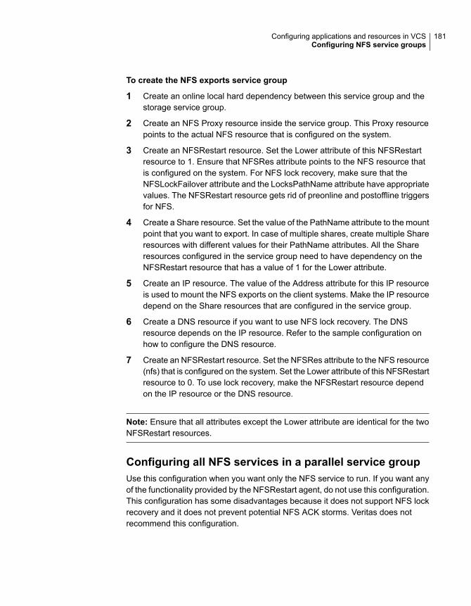
To create the NFS exports service group
1 Create an online local hard dependency between this service group and thestorage service group.
2 Create an NFS Proxy resource inside the service group. This Proxy resourcepoints to the actual NFS resource that is configured on the system.
3 Create an NFSRestart resource. Set the Lower attribute of this NFSRestartresource to 1. Ensure that NFSRes attribute points to the NFS resource thatis configured on the system. For NFS lock recovery, make sure that theNFSLockFailover attribute and the LocksPathName attribute have appropriatevalues. The NFSRestart resource gets rid of preonline and postoffline triggersfor NFS.
4 Create a Share resource. Set the value of the PathName attribute to the mountpoint that you want to export. In case of multiple shares, create multiple Shareresources with different values for their PathName attributes. All the Shareresources configured in the service group need to have dependency on theNFSRestart resource that has a value of 1 for the Lower attribute.
5 Create an IP resource. The value of the Address attribute for this IP resourceis used to mount the NFS exports on the client systems. Make the IP resourcedepend on the Share resources that are configured in the service group.
6 Create a DNS resource if you want to use NFS lock recovery. The DNSresource depends on the IP resource. Refer to the sample configuration onhow to configure the DNS resource.
7 Create an NFSRestart resource. Set the NFSRes attribute to the NFS resource(nfs) that is configured on the system. Set the Lower attribute of this NFSRestartresource to 0. To use lock recovery, make the NFSRestart resource dependon the IP resource or the DNS resource.
Note: Ensure that all attributes except the Lower attribute are identical for the twoNFSRestart resources.
Configuring all NFS services in a parallel service groupUse this configuration when you want only the NFS service to run. If you want anyof the functionality provided by the NFSRestart agent, do not use this configuration.This configuration has some disadvantages because it does not support NFS lockrecovery and it does not prevent potential NFS ACK storms. Veritas does notrecommend this configuration.
181Configuring applications and resources in VCSConfiguring NFS service groups

Creating the NFS service groupThis service group contains an NFS resource and an NFSRestart resource.
To create the NFS service group
1 Configure a separate parallel service group (nfs_grp).
2 Set the value of the AutoStart and Parallel attributes to 1 for the service group.The value for the AutoStartList must contain the list of all the cluster nodes inthe service group.
3 Configure an NFS resource (nfs) inside this service group. You can also putNIC resource in this service group to monitor a NIC.
4 Configure an NFSRestart resource inside this service group. Set the value ofLower attribute to 2. The NFSRes attribute of this resource must point to theNFS resource (nfs) configured on the system. NFSLockFailover is not supportedin this configuration.
Note:
■ NFSLockFailover is not supported in this configuration.
■ This configuration does not prevent potential NFS ACK storms.
■ NFSv4 is not supported in this configuration.
Creating the NFS exports service groupThis service group contains the Share and IP resources for exports. The value forthe PathName attribute for the Share resource must be on shared storage and itmust be visible to all nodes in the cluster.
To create the NFS exports service group
1 Create an NFS Proxy resource inside the service group. This Proxy resourcepoints to the actual NFS resource that is configured on the system.
2 If you configure the backing store for the NFS exports with VxVM, createDiskGroup and Mount resources for the mount point that you want to export.
Refer to Storage agents chapter of the Cluster Server Bundled AgentsReference Guide for details.
3 Create a Share resource. Set the PathName to the mount point that you wantto export. In case of multiple shares, create multiple Share resources withdifferent values for their PathName attributes.
4 Create an IP resource. The value of the Address attribute for this IP resourceis used to mount the NFS exports on the client systems. Make the IP resourcedepend on the Share resources that are configured in the service group.
182Configuring applications and resources in VCSConfiguring NFS service groups

Sample configurationsThe following are the sample configurations for some of the supported NFSconfigurations.
■ See “Sample configuration for a single NFS environment without lock recovery”on page 183.
■ See “Sample configuration for a single NFS environment with lock recovery”on page 185.
■ See “Sample configuration for a single NFSv4 environment” on page 188.
■ See “Sample configuration for a multiple NFSv4 environment” on page 190.
■ See “Sample configuration for a multiple NFS environment without lock recovery”on page 193.
■ See “Sample configuration for a multiple NFS environment with lock recovery”on page 195.
■ See “Sample configuration for configuring NFS with separate storage”on page 199.
■ See “Sample configuration when configuring all NFS services in a parallel servicegroup” on page 201.
Sample configuration for a single NFS environmentwithoutlock recoveryinclude "types.cf"
cluster clus1 (
UseFence = SCSI3
)
system sys1 (
)
system sys2 (
)
group sg11 (
SystemList = { sys1 = 0, sys2 = 1 }
AutoStartList = { sys1 }
)
DiskGroup vcs_dg1 (
DiskGroup = dg1
StartVolumes = 0
StopVolumes = 0
)
183Configuring applications and resources in VCSConfiguring NFS service groups

IP ip_sys1 (
Device @sys1 = en0
Device @sys2 = en0
Address = "10.198.90.198"
NetMask = "255.255.248.0"
)
Mount vcs_dg1_r01_2 (
MountPoint = "/testdir/VITA_dg1_r01_2"
BlockDevice = "/dev/vx/dsk/dg1/dg1_r01_2"
FSType = vxfs
FsckOpt = "-y"
)
Mount vcs_dg1_r0_1 (
MountPoint = "/testdir/VITA_dg1_r0_1"
BlockDevice = "/dev/vx/dsk/dg1/dg1_r0_1"
FSType = vxfs
FsckOpt = "-y"
)
NFSRestart NFSRestart_sg11_L (
NFSRes = nfs
Lower = 1
)
NFSRestart NFSRestart_sg11_U (
NFSRes = nfs
)
NIC nic_sg11_en0 (
Device @sys1 = en0
Device @sys2 = en0
NetworkHosts = { "10.198.88.1" }
)
NFS nfs (
Nservers = 16
)
Share share_dg1_r01_2 (
PathName = "/testdir/VITA_dg1_r01_2"
184Configuring applications and resources in VCSConfiguring NFS service groups

Options = rw
)
Share share_dg1_r0_1 (
PathName = "/testdir/VITA_dg1_r0_1"
Options = rw
)
Volume vol_dg1_r01_2 (
Volume = dg1_r01_2
DiskGroup = dg1
)
Volume vol_dg1_r0_1 (
Volume = dg1_r0_1
DiskGroup = dg1
)
NFSRestart_sg11_L requires nfs
NFSRestart_sg11_L requires vcs_dg1_r01_2
NFSRestart_sg11_L requires vcs_dg1_r0_1
NFSRestart_sg11_U requires ip_sys1
ip_sys1 requires nic_sg11_en0
ip_sys1 requires share_dg1_r01_2
ip_sys1 requires share_dg1_r0_1
share_dg1_r01_2 requires NFSRestart_sg11_L
share_dg1_r0_1 requires NFSRestart_sg11_L
vcs_dg1_r01_2 requires vol_dg1_r01_2
vcs_dg1_r0_1 requires vol_dg1_r0_1
vol_dg1_r01_2 requires vcs_dg1
vol_dg1_r0_1 requires vcs_dg1
Sample configuration for a single NFS environment withlock recoveryinclude "types.cf"
cluster clus1 (
UseFence = SCSI3
)
system sys1 (
)
185Configuring applications and resources in VCSConfiguring NFS service groups

system sys2 (
)
group sg11 (
SystemList = { sys1 = 0, sys2 = 1 }
AutoStartList = { sys1 }
)
DiskGroup vcs_dg1 (
DiskGroup = dg1
StartVolumes = 0
StopVolumes = 0
)
IP ip_sys1 (
Device @sys1 = en0
Device @sys2 = en0
Address = "10.198.90.198"
NetMask = "255.255.248.0"
)
DNS dns_11 (
Domain = "oradb.sym"
TSIGKeyFile = "/Koradb.sym.+157+13021.private"
StealthMasters = { "10.198.90.202" }
ResRecord @sys1 = { sys1 = "10.198.90.198" }
ResRecord @sys2 = { sys2 = "10.198.90.198" }
CreatePTR = 1
OffDelRR = 1
)
Mount vcs_dg1_r01_2 (
MountPoint = "/testdir/VITA_dg1_r01_2"
BlockDevice = "/dev/vx/dsk/dg1/dg1_r01_2"
FSType = vxfs
FsckOpt = "-y"
)
Mount vcs_dg1_r0_1 (
MountPoint = "/testdir/VITA_dg1_r0_1"
BlockDevice = "/dev/vx/dsk/dg1/dg1_r0_1"
FSType = vxfs
FsckOpt = "-y"
)
186Configuring applications and resources in VCSConfiguring NFS service groups

NFS nfs (
)
NFSRestart NFSRestart_sg11_L (
NFSRes = nfs
LocksPathName = "/testdir/VITA_dg1_r01_2"
NFSLockFailover = 1
Lower = 1
)
NFSRestart NFSRestart_sg11_U (
NFSRes = nfs
LocksPathName = "/testdir/VITA_dg1_r01_2"
NFSLockFailover = 1
)
NIC nic_sg11_en0 (
Device @sys1 = en0
Device @sys2 = en0
NetworkHosts = { "10.198.88.1" }
)
Share share_dg1_r01_2 (
PathName = "/testdir/VITA_dg1_r01_2"
Options = rw
)
Share share_dg1_r0_1 (
PathName = "/testdir/VITA_dg1_r0_1"
Options = rw
)
Volume vol_dg1_r01_2 (
Volume = dg1_r01_2
DiskGroup = dg1
)
Volume vol_dg1_r0_1 (
Volume = dg1_r0_1
DiskGroup = dg1
)
NFSRestart_sg11_L requires nfs
187Configuring applications and resources in VCSConfiguring NFS service groups

NFSRestart_sg11_L requires vcs_dg1_r01_2
NFSRestart_sg11_L requires vcs_dg1_r0_1
NFSRestart_sg11_U requires dns_11
dns_11 requires ip_sys1
ip_sys1 requires nic_sg11_en0
ip_sys1 requires share_dg1_r01_2
ip_sys1 requires share_dg1_r0_1
share_dg1_r01_2 requires NFSRestart_sg11_L
share_dg1_r0_1 requires NFSRestart_sg11_L
vcs_dg1_r01_2 requires vol_dg1_r01_2
vcs_dg1_r0_1 requires vol_dg1_r0_1
vol_dg1_r01_2 requires vcs_dg1
vol_dg1_r0_1 requires vcs_dg1
Sample configuration for a single NFSv4 environmentinclude "types.cf"
cluster clus1 (
UseFence = SCSI3
)
system sys1 (
)
system sys2 (
)
group sg11 (
SystemList = { sys1 = 0, sys2 = 1 }
AutoStartList = { sys1 }
)
DiskGroup vcs_dg1 (
DiskGroup = dg1
StartVolumes = 0
StopVolumes = 0
)
IP ip_sys1 (
Device @sys1 = en0
Device @sys2 = en0
Address = "10.198.90.198"
NetMask = "255.255.248.0"
)
DNS dns_11 (
Domain = "oradb.sym"
TSIGKeyFile = "/Koradb.sym.+157+13021.private"
StealthMasters = { "10.198.90.202" }
188Configuring applications and resources in VCSConfiguring NFS service groups

ResRecord @sys1 = { sys1 = "10.198.90.198" }
ResRecord @sys2 = { sys2 = "10.198.90.198" }
CreatePTR = 1
OffDelRR = 1
)
Mount vcs_dg1_r01_2 (
MountPoint = "/testdir/VITA_dg1_r01_2"
BlockDevice = "/dev/vx/dsk/dg1/dg1_r01_2"
FSType = vxfs
FsckOpt = "-y"
)
Mount vcs_dg1_r0_1 (
MountPoint = "/testdir/VITA_dg1_r0_1"
BlockDevice = "/dev/vx/dsk/dg1/dg1_r0_1"
FSType = vxfs
FsckOpt = "-y"
)
NFS nfs (
NFSv4Root = "/"
)
NFSRestart NFSRestart_sg11_L (
NFSRes = nfs
LocksPathName = "/testdir/VITA_dg1_r01_2"
NFSLockFailover = 1
Lower = 1
)
NFSRestart NFSRestart_sg11_U (
NFSRes = nfs
LocksPathName = "/testdir/VITA_dg1_r01_2"
NFSLockFailover = 1
)
NIC nic_sg11_en0 (
Device @sys1 = en0
Device @sys2 = en0
NetworkHosts = { "10.198.88.1" }
NetworkType = ether
)
Share share_dg1_r01_2 (
PathName = "/testdir/VITA_dg1_r01_2"
Options = rw
)
189Configuring applications and resources in VCSConfiguring NFS service groups
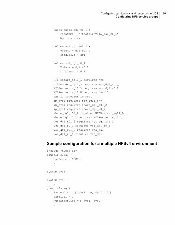
Share share_dg1_r0_1 (
PathName = "/testdir/VITA_dg1_r0_1"
Options = rw
)
Volume vol_dg1_r01_2 (
Volume = dg1_r01_2
DiskGroup = dg1
)
Volume vol_dg1_r0_1 (
Volume = dg1_r0_1
DiskGroup = dg1
)
NFSRestart_sg11_L requires nfs
NFSRestart_sg11_L requires vcs_dg1_r01_2
NFSRestart_sg11_L requires vcs_dg1_r0_1
NFSRestart_sg11_U requires dns_11
dns_11 requires ip_sys1
ip_sys1 requires nic_sg11_en0
ip_sys1 requires share_dg1_r01_2
ip_sys1 requires share_dg1_r0_1
share_dg1_r01_2 requires NFSRestart_sg11_L
share_dg1_r0_1 requires NFSRestart_sg11_L
vcs_dg1_r01_2 requires vol_dg1_r01_2
vcs_dg1_r0_1 requires vol_dg1_r0_1
vol_dg1_r01_2 requires vcs_dg1
vol_dg1_r0_1 requires vcs_dg1
Sample configuration for a multiple NFSv4 environmentinclude "types.cf"
cluster clus1 (
UseFence = SCSI3
)
system sys1 (
)
system sys2 (
)
group nfs_sg (
SystemList = { sys1 = 0, sys2 = 1 }
Parallel = 1
AutoStartList = { sys1, sys2 }
)
190Configuring applications and resources in VCSConfiguring NFS service groups
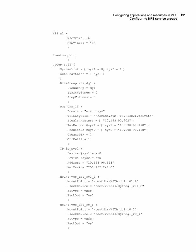
NFS n1 (
Nservers = 6
NFSv4Root = "/"
)
Phantom ph1 (
)
group sg11 (
SystemList = { sys1 = 0, sys2 = 1 }
AutoStartList = { sys1 }
)
DiskGroup vcs_dg1 (
DiskGroup = dg1
StartVolumes = 0
StopVolumes = 0
)
DNS dns_11 (
Domain = "oradb.sym"
TSIGKeyFile = "/Koradb.sym.+157+13021.private"
StealthMasters = { "10.198.90.202" }
ResRecord @sys1 = { sys1 = "10.198.90.198" }
ResRecord @sys2 = { sys2 = "10.198.90.198" }
CreatePTR = 1
OffDelRR = 1
)
IP ip_sys2 (
Device @sys1 = en0
Device @sys2 = en0
Address = "10.198.90.198"
NetMask = "255.255.248.0"
)
Mount vcs_dg1_r01_2 (
MountPoint = "/testdir/VITA_dg1_r01_2"
BlockDevice = "/dev/vx/dsk/dg1/dg1_r01_2"
FSType = vxfs
FsckOpt = "-y"
)
Mount vcs_dg1_r0_1 (
MountPoint = "/testdir/VITA_dg1_r0_1"
BlockDevice = "/dev/vx/dsk/dg1/dg1_r0_1"
FSType = vxfs
FsckOpt = "-y"
)
191Configuring applications and resources in VCSConfiguring NFS service groups

NFSRestart NFSRestart_sg11_L (
NFSRes = n1
Lower = 1
LocksPathName = "/testdir/VITA_dg1_r01_2"
NFSLockFailover = 1
)
NFSRestart NFSRestart_sg11_U (
NFSRes = n1
LocksPathName = "/testdir/VITA_dg1_r01_2"
NFSLockFailover = 1
)
NIC nic_sg11_en0 (
Device @sys1 = en0
Device @sys2 = en0
NetworkHosts = { "10.198.88.1" }
)
Proxy p11 (
TargetResName = n1
)
Share share_dg1_r01_2 (
PathName = "/testdir/VITA_dg1_r01_2"
Options = rw
)
Share share_dg1_r0_1 (
PathName = "/testdir/VITA_dg1_r0_1"
Options = rw
)
Volume vol_dg1_r01_2 (
Volume = dg1_r01_2
DiskGroup = dg1
)
Volume vol_dg1_r0_1 (
Volume = dg1_r0_1
DiskGroup = dg1
)
requires group nfs_sg online local firm
NFSRestart_sg11_L requires p11
NFSRestart_sg11_L requires vcs_dg1_r01_2
NFSRestart_sg11_L requires vcs_dg1_r0_1
NFSRestart_sg11_U requires dns_11
dns_11 requires ip_sys1
ip_sys1 requires nic_sg11_en0
ip_sys1 requires share_dg1_r01_2
192Configuring applications and resources in VCSConfiguring NFS service groups

ip_sys1 requires share_dg1_r0_1
share_dg1_r01_2 requires NFSRestart_sg11_L
share_dg1_r0_1 requires NFSRestart_sg11_L
vcs_dg1_r01_2 requires vol_dg1_r01_2
vcs_dg1_r0_1 requires vol_dg1_r0_1
vol_dg1_r01_2 requires vcs_dg1
vol_dg1_r0_1 requires vcs_dg1
Sample configuration for a multiple NFS environmentwithout lock recovery
include "types.cf"
cluster clus1 (
UseFence = SCSI3
)
system sys1 (
)
system sys2 (
)
group nfs_sg (
SystemList = { sys1 = 0, sys2 = 1 }
Parallel = 1
AutoStartList = { sys1, sys2 }
)
NFS n1 (
Nservers = 6
)
Phantom ph1 (
)
group sg11 (
SystemList = { sys1 = 0, sys2 = 1 }
AutoStartList = { sys1 }
)
193Configuring applications and resources in VCSConfiguring NFS service groups

DiskGroup vcs_dg1 (
DiskGroup = dg1
StartVolumes = 0
StopVolumes = 0
)
IP ip_sys1 (
Device @sys1 = en0
Device @sys2 = en0
Address = "10.198.90.198"
NetMask = "255.255.248.0"
)
Mount vcs_dg1_r01_2 (
MountPoint = "/testdir/VITA_dg1_r01_2"
BlockDevice = "/dev/vx/dsk/dg1/dg1_r01_2"
FSType = vxfs
FsckOpt = "-y"
)
Mount vcs_dg1_r0_1 (
MountPoint = "/testdir/VITA_dg1_r0_1"
BlockDevice = "/dev/vx/dsk/dg1/dg1_r0_1"
FSType = vxfs
FsckOpt = "-y"
)
NFSRestart NFSRestart_sg11_L (
NFSRes = n1
Lower = 1
)
NFSRestart NFSRestart_sg11_U (
NFSRes = n1
)
NIC nic_sg11_en0 (
Device @sys1 = en0
Device @sys2 = en0
NetworkHosts = { "10.198.88.1" }
)
Proxy p11 (
194Configuring applications and resources in VCSConfiguring NFS service groups
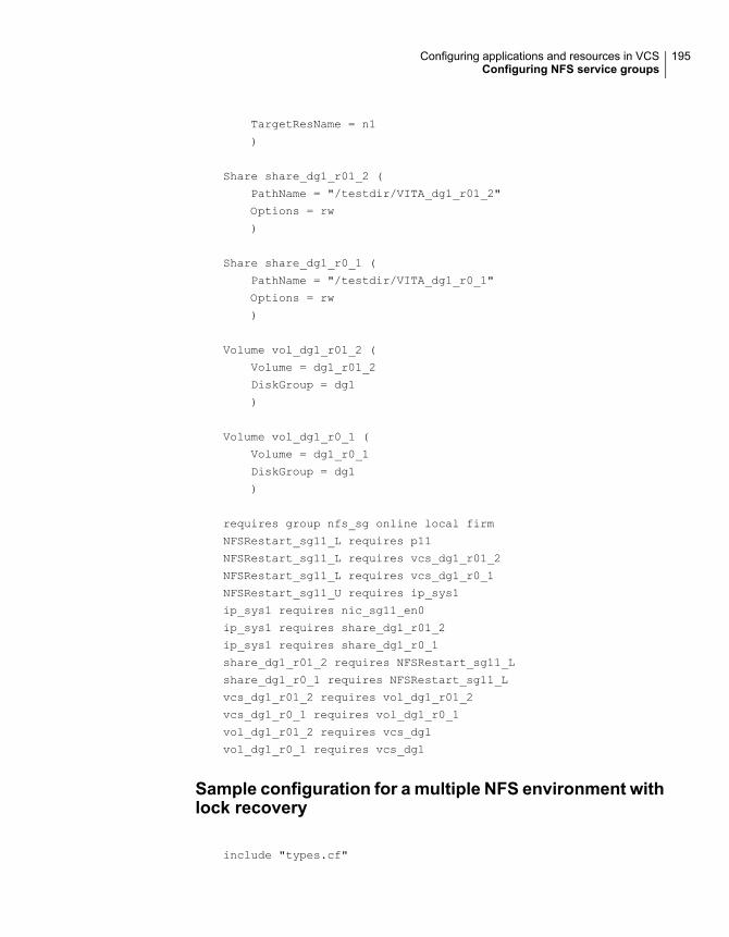
TargetResName = n1
)
Share share_dg1_r01_2 (
PathName = "/testdir/VITA_dg1_r01_2"
Options = rw
)
Share share_dg1_r0_1 (
PathName = "/testdir/VITA_dg1_r0_1"
Options = rw
)
Volume vol_dg1_r01_2 (
Volume = dg1_r01_2
DiskGroup = dg1
)
Volume vol_dg1_r0_1 (
Volume = dg1_r0_1
DiskGroup = dg1
)
requires group nfs_sg online local firm
NFSRestart_sg11_L requires p11
NFSRestart_sg11_L requires vcs_dg1_r01_2
NFSRestart_sg11_L requires vcs_dg1_r0_1
NFSRestart_sg11_U requires ip_sys1
ip_sys1 requires nic_sg11_en0
ip_sys1 requires share_dg1_r01_2
ip_sys1 requires share_dg1_r0_1
share_dg1_r01_2 requires NFSRestart_sg11_L
share_dg1_r0_1 requires NFSRestart_sg11_L
vcs_dg1_r01_2 requires vol_dg1_r01_2
vcs_dg1_r0_1 requires vol_dg1_r0_1
vol_dg1_r01_2 requires vcs_dg1
vol_dg1_r0_1 requires vcs_dg1
Sample configuration for a multiple NFS environment withlock recovery
include "types.cf"
195Configuring applications and resources in VCSConfiguring NFS service groups

cluster clus1 (
UseFence = SCSI3
)
system sys1 (
)
system sys2 (
)
group nfs_sg (
SystemList = { sys1 = 0, sys2 = 1 }
Parallel = 1
AutoStartList = { sys1, sys2 }
)
NFS n1 (
Nservers = 6
)
Phantom ph1 (
)
group sg11 (
SystemList = { sys1 = 0, sys2 = 1 }
AutoStartList = { sys1 }
)
DiskGroup vcs_dg1 (
DiskGroup = dg1
StartVolumes = 0
StopVolumes = 0
)
DNS dns_11 (
Domain = "oradb.sym"
TSIGKeyFile = "/Koradb.sym.+157+13021.private"
StealthMasters = { "10.198.90.202" }
ResRecord @sys1 = { sys1 = "10.198.90.198" }
ResRecord @sys2 = { sys2 = "10.198.90.198" }
CreatePTR = 1
196Configuring applications and resources in VCSConfiguring NFS service groups

OffDelRR = 1
)
IP ip_sys1 (
Device @sys1 = en0
Device @sys2 = en0
Address = "10.198.90.198"
NetMask = "255.255.248.0"
)
Mount vcs_dg1_r01_2 (
MountPoint = "/testdir/VITA_dg1_r01_2"
BlockDevice = "/dev/vx/dsk/dg1/dg1_r01_2"
FSType = vxfs
FsckOpt = "-y"
)
Mount vcs_dg1_r0_1 (
MountPoint = "/testdir/VITA_dg1_r0_1"
BlockDevice = "/dev/vx/dsk/dg1/dg1_r0_1"
FSType = vxfs
FsckOpt = "-y"
)
NFSRestart NFSRestart_sg11_L (
NFSRes = n1
Lower = 1
LocksPathName = "/testdir/VITA_dg1_r01_2"
NFSLockFailover = 1
)
NFSRestart NFSRestart_sg11_U (
NFSRes = n1
LocksPathName = "/testdir/VITA_dg1_r01_2"
NFSLockFailover = 1
)
NIC nic_sg11_en0 (
Device @sys1 = en0
Device @sys2 = en0
NetworkHosts = { "10.198.88.1" }
)
Proxy p11 (
197Configuring applications and resources in VCSConfiguring NFS service groups

TargetResName = n1
)
Share share_dg1_r01_2 (
PathName = "/testdir/VITA_dg1_r01_2"
Options = rw
)
Share share_dg1_r0_1 (
PathName = "/testdir/VITA_dg1_r0_1"
Options = rw
)
Volume vol_dg1_r01_2 (
Volume = dg1_r01_2
DiskGroup = dg1
)
Volume vol_dg1_r0_1 (
Volume = dg1_r0_1
DiskGroup = dg1
)
requires group nfs_sg online local firm
NFSRestart_sg11_L requires p11
NFSRestart_sg11_L requires vcs_dg1_r01_2
NFSRestart_sg11_L requires vcs_dg1_r0_1
NFSRestart_sg11_U requires dns_11
dns_11 requires ip_sys1
ip_sys1 requires nic_sg11_en0
ip_sys1 requires share_dg1_r01_2
ip_sys1 requires share_dg1_r0_1
share_dg1_r01_2 requires NFSRestart_sg11_L
share_dg1_r0_1 requires NFSRestart_sg11_L
vcs_dg1_r01_2 requires vol_dg1_r01_2
vcs_dg1_r0_1 requires vol_dg1_r0_1
vol_dg1_r01_2 requires vcs_dg1
vol_dg1_r0_1 requires vcs_dg1
198Configuring applications and resources in VCSConfiguring NFS service groups

Sample configuration for configuring NFS with separatestorageinclude "types.cf"
cluster clus1 (
UseFence = SCSI3
)
system sys1 (
)
system sys2 (
)
group nfs_sg (
SystemList = { sys1 = 0, sys2 = 1 }
Parallel = 1
AutoStartList = { sys1, sys2 }
)
NFS n1 (
Nservers = 6
)
Phantom ph1 (
)
group sg11storage (
SystemList = { sys1 = 0, sys2 = 1 }
)
DiskGroup vcs_dg1 (
DiskGroup = dg1
StartVolumes = 0
StopVolumes = 0
)
Mount vcs_dg1_r01_2 (
MountPoint = "/testdir/VITA_dg1_r01_2"
BlockDevice = "/dev/vx/dsk/dg1/dg1_r01_2"
FSType = vxfs
FsckOpt = "-y"
)
199Configuring applications and resources in VCSConfiguring NFS service groups

Mount vcs_dg1_r0_1 (
MountPoint = "/testdir/VITA_dg1_r0_1"
BlockDevice = "/dev/vx/dsk/dg1/dg1_r0_1"
FSType = vxfs
FsckOpt = "-y"
)
Volume vol_dg1_r01_2 (
Volume = dg1_r01_2
DiskGroup = dg1
)
Volume vol_dg1_r0_1 (
Volume = dg1_r0_1
DiskGroup = dg1
)
vcs_dg1_r01_2 requires vol_dg1_r01_2
vcs_dg1_r0_1 requires vol_dg1_r0_1
vol_dg1_r01_2 requires vcs_dg1
vol_dg1_r0_1 requires vcs_dg1
group sg11 (
SystemList = { sys1 = 0, sys2 = 1 }
AutoStartList = { sys1 }
)
IP sys1 (
Device @sys1 = en0
Device @sys2 = en0
Address = "10.198.90.198"
NetMask = "255.255.248.0"
)
NFSRestart NFSRestart_sg11_L (
NFSRes = n1
Lower = 1
)
NFSRestart NFSRestart_sg11_U (
NFSRes = n1
)
200Configuring applications and resources in VCSConfiguring NFS service groups
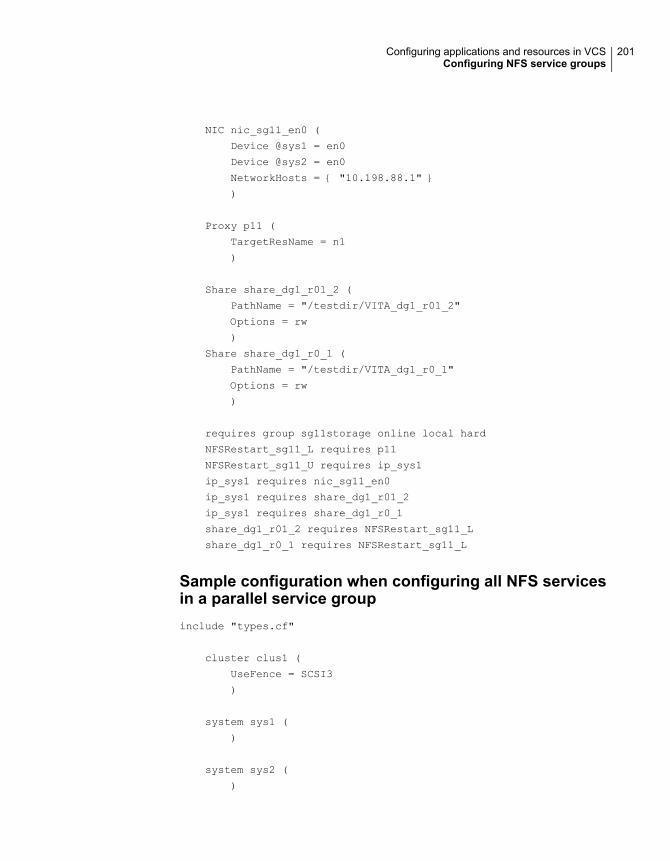
NIC nic_sg11_en0 (
Device @sys1 = en0
Device @sys2 = en0
NetworkHosts = { "10.198.88.1" }
)
Proxy p11 (
TargetResName = n1
)
Share share_dg1_r01_2 (
PathName = "/testdir/VITA_dg1_r01_2"
Options = rw
)
Share share_dg1_r0_1 (
PathName = "/testdir/VITA_dg1_r0_1"
Options = rw
)
requires group sg11storage online local hard
NFSRestart_sg11_L requires p11
NFSRestart_sg11_U requires ip_sys1
ip_sys1 requires nic_sg11_en0
ip_sys1 requires share_dg1_r01_2
ip_sys1 requires share_dg1_r0_1
share_dg1_r01_2 requires NFSRestart_sg11_L
share_dg1_r0_1 requires NFSRestart_sg11_L
Sample configuration when configuring all NFS servicesin a parallel service groupinclude "types.cf"
cluster clus1 (
UseFence = SCSI3
)
system sys1 (
)
system sys2 (
)
201Configuring applications and resources in VCSConfiguring NFS service groups

group nfs_sg (
SystemList = { sys1 = 0, sys2 = 1 }
Parallel = 1
AutoStartList = { sys1, sys2 }
)
NFS n1 (
Nservers = 6
)
NFSRestart nfsrestart (
NFSRes = n1
Lower = 2
)
nfsrestart requires n1
group sg11 (
SystemList = { sys1 = 0, sys2 = 1 }
AutoStartList = { sys1 }
)
IP ip_sys1 (
Device @sys1 = en0
Device @sys2 = en0
Address = "10.198.90.198"
NetMask = "255.255.248.0"
)
NIC nic_sg11_en0 (
Device @sys1 = en0
Device @sys2 = en0
NetworkHosts = { "10.198.88.1" }
)
Proxy p11 (
TargetResName = n1
)
Share share_dg1_r01_2 (
PathName = "/testdir/VITA_dg1_r01_2"
202Configuring applications and resources in VCSConfiguring NFS service groups

Options = rw
)
Share share_dg1_r0_1 (
PathName = "/testdir/VITA_dg1_r0_1"
Options = rw
)
requires group sg11storage online local hard
ip_sys1 requires nic_sg11_en0
ip_sys1 requires share_dg1_r01_2
ip_sys1 requires share_dg1_r0_1
share_dg1_r01_2 requires p11
share_dg1_r0_1 requires p11
group sg11storage (
SystemList = { sys1 = 0, sys2 = 1 }
)
DiskGroup vcs_dg1 (
DiskGroup = dg1
StartVolumes = 0
StopVolumes = 0
)
Mount vcs_dg1_r01_2 (
MountPoint = "/testdir/VITA_dg1_r01_2"
BlockDevice = "/dev/vx/dsk/dg1/dg1_r01_2"
FSType = vxfs
FsckOpt = "-y"
)
Mount vcs_dg1_r0_1 (
MountPoint = "/testdir/VITA_dg1_r0_1"
BlockDevice = "/dev/vx/dsk/dg1/dg1_r0_1"
FSType = vxfs
FsckOpt = "-y"
)
Volume vol_dg1_r01_2 (
Volume = dg1_r01_2
DiskGroup = dg1
)
203Configuring applications and resources in VCSConfiguring NFS service groups

Volume vol_dg1_r0_1 (
Volume = dg1_r0_1
DiskGroup = dg1
)
vcs_dg1_r01_2 requires vol_dg1_r01_2
vcs_dg1_r0_1 requires vol_dg1_r0_1
vol_dg1_r01_2 requires vcs_dg1
vol_dg1_r0_1 requires vcs_dg1
About configuring the RemoteGroup agentThe RemoteGroup agent monitors and manages service groups in a remote cluster.Use the RemoteGroup agent to establish dependencies between applications thatare configured on different VCS clusters.
For example, you configure an Apache resource in a local cluster, and configurean Oracle resource in a remote cluster. In this example, the Apache resource inthe local cluster depends on the Oracle resource in the remote cluster. You canuse the RemoteGroup agent to establish this dependency between the servicegroups that contain the Apache resource and the Oracle resource, if you add theRemoteGroup agent as a resource in the Apache service group.
See the Cluster Server Bundled Agents Reference Guide for more informationabout the agent and its attributes.
Note: RemoteGroup agent configurations and Virtual Business Serviceconfigurations are mutually exclusive though both provide multi-tier applicationsupport.
For information about Virtual Business Services, see the Virtual BusinessService–Availability User's Guide.
About the ControlMode attributeIn the ControlMode attribute, you can use these values, depending on your needs:OnOff, MonitorOnly, and OnlineOnly.
About the OnOff modeSelect the OnOff value of this attribute when you want the RemoteGroup resourceto manage the remote service group completely.
204Configuring applications and resources in VCSAbout configuring the RemoteGroup agent

In case of one-to-one mapping, set the value of the AutoFailOver attribute of theremote service group to 0. This avoids unnecessary onlining or offlining of theremote service group.
About the MonitorOnly modeSelect the MonitorOnly value of this attribute when you want to monitor the stateof the remote service group. When you choose the MonitorOnly attribute, theRemoteGroup agent does not have control over the remote service group andcannot bring it online or take it offline.
The remote service group should be in an ONLINE state before you bring theRemoteGroup resource online.
Veritas recommends that the AutoFailOver attribute of the remote service groupbe set to 1.
About the OnlineOnly modeSelect the OnlineOnly value of this attribute when the remote service group takesa long time to come online or to go offline. When you use OnlineOnly for theControlMode attribute, a switch or fail over of the local service group withVCSSysName set to ANY does not cause the remote service group to be takenoffline and brought online.
Taking the RemoteGroup resource offline does not take the remote service groupoffline.
If you choose one-to-one mapping between the local nodes and remote nodes,then the value of the AutoFailOver attribute of the remote service group must be0.
Note: When you set the value of ControlMode to OnlineOnly or to MonitorOnly, therecommend value of the VCSSysName attribute of the RemoteGroup resource isANY. If you want one-to-one mapping between the local nodes and the remotenodes, then a switch or fail over of local service group is impossible. It is importantto note that in both these configurations the RemoteGroup agent does not take theremote service group offline.
About the ReturnIntOffline attributeThe ReturnIntOffline attribute can take one of three values: RemotePartial,RemoteOffline, and RemoteFaulted.
205Configuring applications and resources in VCSAbout configuring the RemoteGroup agent

These values are not mutually exclusive and can be used in combination with oneanother. You must set the IntentionalOffline attribute of RemoteGroup resource to1 for the ReturnIntOffline attribute to work.
About the RemotePartial optionSelect the RemotePartial value of this attribute when you want the RemoteGroupresource to return an IntentionalOffline when the remote service group is in anONLINE | PARTIAL state.
About the RemoteOffline optionSelect the RemoteOffline value of this attribute when you want the RemoteGroupresource to return an IntentionalOffline when the remote service group is in anOFFLINE state.
About the RemoteFaulted optionSelect the RemoteFaulted value of this attribute when you want the RemoteGroupresource to return an IntentionalOffline when the remote service group is in anOFFLINE | FAULTED state.
Configuring a RemoteGroup resourceThis topic describes how to configure a RemoteGroup resource.
In this example configuration, the following is true:
■ VCS cluster (cluster1) provides high availability for Web services.Configure a VCS service group (ApacheGroup) with an agent to monitor theWeb server (for example Apache) to monitor the Web services.
■ VCS cluster (cluster2) provides high availability for the database required bythe Web-services.Configure a VCS service group (OracleGroup) with a database agent (forexample Oracle) to monitor the database.
The database resource must come online before the Web server comes online.You create this dependency using the RemoteGroup agent.
To configure the RemoteGroup agent
1 Add a RemoteGroup resource in the ApacheGroup service group (in cluster1).
2 Link the resources such that the Web server resource depends on theRemoteGroup resource.
206Configuring applications and resources in VCSAbout configuring the RemoteGroup agent

3 Configure the following RemoteGroup resource items to monitor or managethe service group that contains the database resource:
■ IpAddress:Set to the IP address or DNS name of a node in cluster2. You can also setthis to a virtual IP address.
■ GroupNameSet to OracleGroup.
■ ControlModeSet to OnOff.
■ UsernameSet to the name of a user having administrative privileges for OracleGroup.
■ PasswordEncrypted password for defined in Username. Encrypt the password usingthe vcsencrypt -agent command.
■ VCSSysNameSet to local, per-node values.VCSSysName@local1—Set this value to remote1.VCSSysName@local2—Set this value to remote2.
Note: If the remote cluster runs in secure mode, you must set the value forDomainType or BrokerIp attributes.
4 Set the value of the AutoFailOver attribute of the OracleGroup to 0.
Service group behavior with the RemoteGroup agentConsider the following potential actions to better understand this solution.
Bringing the Apache service group onlineFollowing are the dependencies to bring the Apache service group online:
■ The Apache resource depends on the RemoteGroup resource.
■ The RemoteGroup agent communicates to the remote cluster and authenticatesthe specified user.
■ The RemoteGroup agent brings the database service group online in cluster2.
■ The Apache resource comes online after the RemoteGroup resource is online.
207Configuring applications and resources in VCSAbout configuring the RemoteGroup agent

Thus, you establish an application-level dependency across two different VCSclusters. The Apache resource does not go online unless the RemoteGroup goesonline. The RemoteGroup resource does not go online unless the database servicegroup goes online.
Unexpected offline of the database service groupFollowing are the sequence of actions when the database service group isunexpectedly brought offline:
■ The RemoteGroup resource detects that the database group has gone OFFLINEor has FAULTED.
■ The RemoteGroup resource goes into a FAULTED state.
■ All the resources in the Apache service group are taken offline on the node.
■ The Apache group fails over to another node.
■ As part of the fail over, the Oracle service group goes online on another nodein cluster2.
Taking the Apache service group offlineFollowing are the sequence of actions when the Apache service group is takenoffline:
■ All the resources dependant on the RemoteGroup resource are taken offline.
■ The RemoteGroup agent tries to take the Oracle service group offline.
■ Once the Oracle service group goes offline, the RemoteGroup goes offline.
Thus, the Web server is taken offline before the database goes offline.
Configuring RemoteGroup resources in parallel servicegroupsWhen a RemoteGroup resource is configured inside parallel service groups, it cancome online on all the cluster nodes, including the offline nodes. Multiple instancesof the RemoteGroup resource on cluster nodes can probe the state of a remoteservice group.
Note: The RemoteGroup resource automatically detects whether it is configuredfor a parallel service group or for a failover service group. No additional configurationis required to enable the RemoteGroup resource for parallel service groups.
A RemoteGroup resource in parallel service groups has the following characteristics:
208Configuring applications and resources in VCSAbout configuring the RemoteGroup agent

■ The RemoteGroup resource continues to monitor the remote service group evenwhen the resource is offline.
■ The RemoteGroup resource does not take the remote service group offline ifthe resource is online anywhere in the cluster.
■ After an agent restarts, the RemoteGroup resource does not return offline if theresource is online on another cluster node.
■ The RemoteGroup resource takes the remote service group offline if it is theonly instance of RemoteGroup resource online in the cluster.
■ An attempt to bring a RemoteGroup resource online has no effect if the sameresource instance is online on another node in the cluster.
About configuring Samba service groupsYou can configure Samba in parallel configurations or failover configurations withVCS.
Refer to the Cluster Server Bundled Agents Reference Guide for platform-specificdetails and examples of the attributes of the Samba family of agents.
Sample configuration for Samba in a failover configurationThe configuration contains a failover service group containing SambaServer,NetBios, IP, NIC, and SambaShare resources. You can configure the sameNetBiosName and Interfaces attribute values for all nodes because the resourcecomes online only on one node at a time.
include "types.cf"
cluster clus1 (
)
system sys1(
)
system sys2(
)
group smbserver (
SystemList = { sys1= 0, sys2= 1 }
)
IP ip (
209Configuring applications and resources in VCSAbout configuring Samba service groups

Device = en0
Address = "10.209.114.201"
NetMask = "255.255.252.0"
)
NIC nic (
Device = en0
NetworkHosts = { "10.209.74.43" }
)
NetBios nmb (
SambaServerRes = smb
NetBiosName = smb_vcs
Interfaces = { "10.209.114.201" }
)
SambaServer smb (
ConfFile = "/etc/samba/smb.conf"
LockDir = "/var/run"
SambaTopDir = "/usr"
)
SambaShare smb_share (
SambaServerRes = smb
ShareName = share1
ShareOptions = "path = /samba_share/; public = yes;
writable = yes"
)
ip requires nic
nmb requires smb
smb requires ip
smb_share requires nmb
Configuring the Coordination Point agentTo monitor I/O fencing coordination points, configure the Coordination Point agentin the VCS cluster where you have configured I/O fencing.
For server-based fencing, you can either use the -fencing option of the installerto configure the agent or you can manually configure the agent. For disk-basedfencing, you must manually configure the agent.
210Configuring applications and resources in VCSConfiguring the Coordination Point agent

See the Cluster Server Bundled Agents Reference Guide for more information onthe agent.
See the Cluster Server Installation Guide for instructions to configure the agent.
About migration of data from LVM volumes toVxVM volumes
VCS supports online migration of data from LVM volumes to VxVM volumes in VCSHA environments.
You can run the vxmigadm utility to migrate data from LVM volumes to VxVMvolumes. The vxmigadm utility integrates seamlessly with VCS, which monitors theLVM volumes. During the data migration, the vxmigadm utility adds new resourcesto monitor the VxVM disk group and VxVM volumes. It keeps track of thedependencies among VCS resources and makes the required updates to thesedependencies. When migration is complete, the dependency of any application onLVM volumes is removed.
For more information, see the Veritas InfoScale 7.2 Solutions Guide.
About testing resource failover by using HA firedrills
Configuring high availability for a database or an application requires severalinfrastructure and configuration settings on multiple systems. However, clusterenvironments are subject to change after the initial setup. Administrators add disks,create new disk groups and volumes, add new cluster nodes, or new NICs toupgrade and maintain the infrastructure. Keeping the cluster configuration updatedwith the changing infrastructure is critical.
HA fire drills detect discrepancies between the VCS configuration and the underlyinginfrastructure on a node; discrepancies that might prevent a service group fromgoing online on a specific node.
See the Cluster Server Bundled Agents Reference Guide for information on whichagents support HA fire drills.
About HA fire drillsThe HA fire drill (earlier known as virtual fire drill) feature uses the Action functionassociated with the agent. The Action functions of the supported agents are updated
211Configuring applications and resources in VCSAbout migration of data from LVM volumes to VxVM volumes
to support the HA fire drill functionality—running infrastructure checks and fixingspecific errors.
The infrastructure check verifies the resources defined in the VCS configurationfile (main.cf) have the required infrastructure to fail over on another node. Forexample, an infrastructure check for the Mount resource verifies the existence ofthe mount directory defined in the MountPoint attribute for the resource.
You can run an infrastructure check only when the service group is online. Thecheck verifies that the specified node is a viable failover target capable of hostingthe service group.
The HA fire drill provides an option to fix specific errors detected during theinfrastructure check.
About running an HA fire drillYou can run a HA fire drill from the command line or from Cluster Manager (JavaConsole).
See “Running HA fire drills” on page 164.
212Configuring applications and resources in VCSAbout testing resource failover by using HA fire drills
VCS communication andoperations
■ Chapter 7. About communications, membership, and data protection in thecluster
■ Chapter 8. Administering I/O fencing
■ Chapter 9. Controlling VCS behavior
■ Chapter 10. The role of service group dependencies
3Section

About communications,membership, and dataprotection in the cluster
This chapter includes the following topics:
■ About cluster communications
■ About cluster membership
■ About membership arbitration
■ About data protection
■ About I/O fencing configuration files
■ Examples of VCS operation with I/O fencing
■ About cluster membership and data protection without I/O fencing
■ Examples of VCS operation without I/O fencing
■ Summary of best practices for cluster communications
About cluster communicationsVCS uses local communications on a system and system-to-system communications.
See “About intra-system communications” on page 215.
See “About inter-system cluster communications” on page 215.
7Chapter

About intra-system communicationsWithin a system, the VCS engine (VCS High Availability Daemon) uses aVCS-specific communication protocol known as Inter Process Messaging (IPM) tocommunicate with the GUI, the command line, and the agents.
Figure 7-1 shows basic communication on a single VCS system. Note that agentsonly communicate with High Availability Daemon (HAD) and never communicatewith each other.
Figure 7-1 Basic communication on a single VCS system
AGENT COMMAND-LINEUTILITIES
VCS HIGH AVAILABILITY DAEMON (HAD)
AGENT GUI
Figure 7-2 depicts communication from a single agent to HAD.
Figure 7-2 Communication from a single agent to HAD
ControlStatus
AGENT-SPECIFIC CODE
AGENT FRAMEWORK
HAD
The agent uses the agent framework, which is compiled into the agent itself. Foreach resource type configured in a cluster, an agent runs on each cluster system.The agent handles all resources of that type. The engine passes commands to theagent and the agent returns the status of command execution. For example, anagent is commanded to bring a resource online. The agent responds back with thesuccess (or failure) of the operation. Once the resource is online, the agentcommunicates with the engine only if this status changes.
About inter-system cluster communicationsVCS uses the cluster interconnect for network communications between clustersystems. Each system runs as an independent unit and shares information at thecluster level. On each system the VCS High Availability Daemon (HAD), which hasthe decision logic for the cluster, maintains a view of the cluster configuration. This
215About communications, membership, and data protection in the clusterAbout cluster communications

daemon operates as a replicated state machine, which means all systems in thecluster have a synchronized state of the cluster configuration. This is accomplishedby the following:
■ All systems run an identical version of HAD.
■ HAD on each system maintains the state of its own resources, and sends allcluster information about the local system to all other machines in the cluster.
■ HAD on each system receives information from the other cluster systems toupdate its own view of the cluster.
■ Each system follows the same code path for actions on the cluster.
The replicated state machine communicates over a purpose-built communicationspackage consisting of two components, Group Membership Services/AtomicBroadcast (GAB) and Low Latency Transport (LLT).
See “About Group Membership Services/Atomic Broadcast (GAB)” on page 216.
See “About Low Latency Transport (LLT)” on page 217.
Figure 7-3 illustrates the overall communications paths between two systems ofthe replicated state machine model.
Figure 7-3 Cluster communications with replicated state machine
UserSpace HAD
KernelSpace
AGENTAGENT
GAB
LLT
UserSpaceHAD
KernelSpace
AGENTAGENT
GAB
LLT
About Group Membership Services/Atomic Broadcast(GAB)The Group Membership Services/Atomic Broadcast protocol (GAB) is responsiblefor cluster membership and reliable cluster communications.
GAB has the following two major functions:
■ Cluster membershipGAB maintains cluster membership by receiving input on the status of theheartbeat from each system via LLT. When a system no longer receivesheartbeats from a cluster peer, LLT passes the heartbeat loss notification to
216About communications, membership, and data protection in the clusterAbout cluster communications

GAB. GAB marks the peer as DOWN and excludes it from the cluster. In mostconfigurations, membership arbitration is used to prevent network partitions.
■ Cluster communicationsGAB’s second function is reliable cluster communications. GAB provides orderedguaranteed delivery of messages to all cluster systems. The Atomic Broadcastfunctionality is used by HAD to ensure that all systems within the cluster receiveall configuration change messages, or are rolled back to the previous state,much like a database atomic commit. While the communications function inGAB is known as Atomic Broadcast, no actual network broadcast traffic isgenerated. An Atomic Broadcast message is a series of point to point unicastmessages from the sending system to each receiving system, with acorresponding acknowledgement from each receiving system.
About Low Latency Transport (LLT)The Low Latency Transport protocol is used for all cluster communications as ahigh-performance, low-latency replacement for the IP stack.
LLT has the following two major functions:
■ Traffic distributionLLT provides the communications backbone for GAB. LLT distributes (loadbalances) inter-system communication across all configured network links. Thisdistribution ensures all cluster communications are evenly distributed across allnetwork links for performance and fault resilience. If a link fails, traffic is redirectedto the remaining links. A maximum of eight network links are supported.
■ HeartbeatLLT is responsible for sending and receiving heartbeat traffic over eachconfigured network link. The heartbeat traffic is point to point unicast. LLT usesethernet broadcast to learn the address of the nodes in the cluster. All othercluster communications, including all status and configuration traffic is point topoint unicast. The heartbeat is used by the Group Membership Services todetermine cluster membership.
The heartbeat signal is defined as follows:
■ LLT on each system in the cluster sends heartbeat packets out on all configuredLLT interfaces every half second.
■ LLT on each system tracks the heartbeat status from each peer on eachconfigured LLT interface.
■ LLT on each system forwards the heartbeat status of each system in the clusterto the local Group Membership Services function of GAB.
217About communications, membership, and data protection in the clusterAbout cluster communications

■ GAB receives the status of heartbeat from all cluster systems from LLT andmakes membership determination based on this information.
Figure 7-4 shows heartbeat in the cluster.
Figure 7-4 Heartbeat in the cluster
HADUnicast point to pointheartbeat on everyinterface every 0.5second
Each LLT module tracks heartbeatstatus from each peer on eachconfigured interface
LLT forwards heartbeatstatus of each system toGAB
AGENT AGENT AGENT AGENT
HAD
GABGAB
LLTLLT
LLT can be configured to designate specific cluster interconnect links as either highpriority or low priority. High priority links are used for cluster communications toGAB as well as heartbeat signals. Low priority links, during normal operation, areused for heartbeat and link state maintenance only, and the frequency of heartbeatsis reduced to 50% of normal to reduce network overhead.
If there is a failure of all configured high priority links, LLT will switch all clustercommunications traffic to the first available low priority link. Communication trafficwill revert back to the high priority links as soon as they become available.
While not required, best practice recommends to configure at least one low prioritylink, and to configure two high priority links on dedicated cluster interconnects toprovide redundancy in the communications path. Low priority links are typicallyconfigured on the public or administrative network.
If you use different media speed for the private NICs, Veritas recommends that youconfigure the NICs with lesser speed as low-priority links to enhance LLTperformance. With this setting, LLT does active-passive load balancing across theprivate links. At the time of configuration and failover, LLT automatically choosesthe link with high-priority as the active link and uses the low-priority links only whena high-priority link fails.
LLT sends packets on all the configured links in weighted round-robin manner. LLTuses the linkburst parameter which represents the number of back-to-back packetsthat LLT sends on a link before the next link is chosen. In addition to the defaultweighted round-robin based load balancing, LLT also provides destination-basedload balancing. LLT implements destination-based load balancing where the LLT
218About communications, membership, and data protection in the clusterAbout cluster communications

link is chosen based on the destination node id and the port. With destination-basedload balancing, LLT sends all the packets of a particular destination on a link.However, a potential problem with the destination-based load balancing approachis that LLT may not fully utilize the available links if the ports have dissimilar traffic.Veritas recommends destination-based load balancing when the setup has morethan two cluster nodes and more active LLT ports. You must manually configuredestination-based load balancing for your cluster to set up the port to LLT linkmapping.
See “Configuring destination-based load balancing for LLT” on page 99.
LLT on startup sends broadcast packets with LLT node id and cluster id informationonto the LAN to discover any node in the network that has same node id and clusterid pair. Each node in the network replies to this broadcast message with its clusterid, node id, and node name.
LLT on the original node does not start and gives appropriate error in the followingcases:
■ LLT on any other node in the same network is running with the same node idand cluster id pair that it owns.
■ LLT on the original node receives response from a node that does not have anode name entry in the /etc/llthosts file.
About cluster membershipThe current members of the cluster are the systems that are actively participatingin the cluster. It is critical for Cluster Server engine (HAD) to accurately determinecurrent cluster membership in order to take corrective action on system failure andmaintain overall cluster topology.
A change in cluster membership is one of the starting points of the logic to determineif HAD needs to perform any fault handling in the cluster.
There are two aspects to cluster membership, initial joining of the cluster and howmembership is determined once the cluster is up and running.
Initial joining of systems to cluster membershipWhen the cluster initially boots, LLT determines which systems are sending heartbeatsignals, and passes that information to GAB. GAB uses this information in theprocess of seeding the cluster membership.
219About communications, membership, and data protection in the clusterAbout cluster membership

Seeding a new clusterSeeding ensures a new cluster will start with an accurate membership count of thenumber of systems in the cluster. This prevents the possibility of one cluster splittinginto multiple subclusters upon initial startup.
A new cluster can be automatically seeded as follows:
■ When the cluster initially boots, all systems in the cluster are unseeded.
■ GAB checks the number of systems that have been declared to be membersof the cluster in the /etc/gabtab file.The number of systems declared in the cluster is denoted as follows:
/sbin/gabconfig -c -nN
where the variable # is replaced with the number of systems in the cluster.
Note: Veritas recommends that you replace # with the exact number of nodesin the cluster.
■ When GAB on each system detects that the correct number of systems arerunning, based on the number declared in /etc/gabtab and input from LLT, itwill seed.
■ If you have I/O fencing enabled in your cluster and if you have set the GABauto-seeding feature through I/O fencing, GAB automatically seeds the clustereven when some cluster nodes are unavailable.See “Seeding a cluster using the GAB auto-seed parameter through I/O fencing”on page 220.
■ HAD will start on each seeded system. HAD will only run on a system that hasseeded.HAD can provide the HA functionality only when GAB has seeded.
See “Manual seeding of a cluster” on page 221.
Seeding a cluster using the GAB auto-seed parameterthrough I/O fencingIf some of the nodes are not up and running in a cluster, then GAB port does notcome up to avoid any risks of preexisting split-brain. In such cases, you can manuallyseed GAB using the command gabconfig –x to bring the GAB port up.
See “Manual seeding of a cluster” on page 221.
220About communications, membership, and data protection in the clusterAbout cluster membership

However, if you have enabled I/O fencing in the cluster, then I/O fencing can handleany preexisting split-brain in the cluster. You can configure I/O fencing in such away for GAB to automatically seed the cluster. The behavior is as follows:
■ If a number of nodes in a cluster are not up, GAB port (port a) still comes up inall the member-nodes in the cluster.
■ If the coordination points do not have keys from any non-member nodes, I/Ofencing (GAB port b) also comes up.
This feature is disabled by default. You must configure the autoseed_gab_timeout
parameter in the /etc/vxfenmode file to enable the automatic seeding feature ofGAB.
See “About I/O fencing configuration files” on page 244.
To enable GAB auto-seeding parameter of I/O fencing
◆ Set the value of the autoseed_gab_timeout parameter in the /etc/vxfenmode
file to 0 to turn on the feature.
To delay the GAB auto-seed feature, you can also set a value greater thanzero. GAB uses this value to delay auto-seed of the cluster for the given numberof seconds.
To disable GAB auto-seeding parameter of I/O fencing
◆ Set the value of the autoseed_gab_timeout parameter in the /etc/vxfenmode
file to -1 to turn off the feature.
You can also remove the line from the /etc/vxfenmode file.
Manual seeding of a clusterSeeding the cluster manually is appropriate when the number of cluster systemsdeclared in /etc/gabtab is more than the number of systems that will join thecluster.
This can occur if a system is down for maintenance when the cluster comes up.
Warning: It is not recommended to seed the cluster manually unless theadministrator is aware of the risks and implications of the command.
221About communications, membership, and data protection in the clusterAbout cluster membership

Note:
If you have I/O fencing enabled in your cluster, you can set the GAB auto-seedingfeature through I/O fencing so that GAB automatically seeds the cluster even whensome cluster nodes are unavailable.
See “Seeding a cluster using the GAB auto-seed parameter through I/O fencing”on page 220.
Before manually seeding the cluster, check that systems that will join the clusterare able to send and receive heartbeats to each other. Confirm there is no possibilityof a network partition condition in the cluster.
Before manually seeding the cluster, do the following:
■ Check that systems that will join the cluster are able to send and receiveheartbeats to each other.
■ Confirm there is no possibility of a network partition condition in the cluster.
To manually seed the cluster, type the following command:
/sbin/gabconfig -x
Note there is no declaration of the number of systems in the cluster with a manualseed. This command will seed all systems in communication with the system wherethe command is run.
So, make sure not to run this command in more than one node in the cluster.
See “Seeding and I/O fencing” on page 594.
Ongoing cluster membershipOnce the cluster is up and running, a system remains an active member of thecluster as long as peer systems receive a heartbeat signal from that system overthe cluster interconnect. A change in cluster membership is determined as follows:
■ When LLT on a system no longer receives heartbeat messages from a systemon any of the configured LLT interfaces for a predefined time (peerinact), LLTinforms GAB of the heartbeat loss from that specific system.This predefined time is 32 seconds by default, but can be configured.You can set this predefined time with the set-timer peerinact command.See the llttab manual page.
■ When LLT informs GAB of a heartbeat loss, the systems that are remaining inthe cluster coordinate to agree which systems are still actively participating inthe cluster and which are not. This happens during a time period known as GABStable Timeout (5 seconds).
222About communications, membership, and data protection in the clusterAbout cluster membership

VCS has specific error handling that takes effect in the case where the systemsdo not agree.
■ GAB marks the system as DOWN, excludes the system from the clustermembership, and delivers the membership change to the fencing module.
■ The fencing module performs membership arbitration to ensure that there is nota split brain situation and only one functional cohesive cluster continues to run.
The fencing module is turned on by default.
Review the details on actions that occur if the fencing module has been deactivated:
See “About cluster membership and data protection without I/O fencing” on page 255.
About membership arbitrationMembership arbitration is necessary on a perceived membership change becausesystems may falsely appear to be down. When LLT on a system no longer receivesheartbeat messages from another system on any configured LLT interface, GABmarks the system as DOWN. However, if the cluster interconnect network failed,a system can appear to be failed when it actually is not. In most environments whenthis happens, it is caused by an insufficient cluster interconnect networkinfrastructure, usually one that routes all communication links through a single pointof failure.
If all the cluster interconnect links fail, it is possible for one cluster to separate intotwo subclusters, each of which does not know about the other subcluster. The twosubclusters could each carry out recovery actions for the departed systems. Thiscondition is termed split brain.
In a split brain condition, two systems could try to import the same storage andcause data corruption, have an IP address up in two places, or mistakenly run anapplication in two places at once.
Membership arbitration guarantees against such split brain conditions.
About membership arbitration componentsThe components of membership arbitration are the fencing module and thecoordination points.
See “About the fencing module” on page 224.
See “About coordination points” on page 224.
223About communications, membership, and data protection in the clusterAbout membership arbitration

About the fencing moduleEach system in the cluster runs a kernel module called vxfen, or the fencing module.This module is responsible for ensuring valid and current cluster membership duringa membership change through the process of membership arbitration.
vxfen performs the following actions:
■ Registers with the coordination points during normal operation
■ Races for control of the coordination points during membership changes
About coordination pointsCoordination points provide a lock mechanism to determine which nodes get tofence off data drives from other nodes. A node must eject a peer from thecoordination points before it can fence the peer from the data drives. VCS preventssplit-brain when vxfen races for control of the coordination points and the winnerpartition fences the ejected nodes from accessing the data disks.
Note: Typically, a fencing configuration for a cluster must have three coordinationpoints. Veritas Technologies also supports server-based fencing with a single CPserver as its only coordination point with a caveat that this CP server becomes asingle point of failure.
The coordination points can either be disks or servers or both.
■ Coordinator disksDisks that act as coordination points are called coordinator disks. Coordinatordisks are three standard disks or LUNs set aside for I/O fencing during clusterreconfiguration. Coordinator disks do not serve any other storage purpose inthe VCS configuration.You can configure coordinator disks to use Veritas Volume Manager's DynamicMulti-pathing (DMP) feature. Dynamic Multi-pathing (DMP) allows coordinatordisks to take advantage of the path failover and the dynamic adding and removalcapabilities of DMP. So, you can configure I/O fencing to use DMP devices. I/Ofencing uses SCSI-3 disk policy that is dmp-based on the disk device that youuse.
Note: The dmp disk policy for I/O fencing supports both single and multiplehardware paths from a node to the coordinator disks. If few coordinator diskshave multiple hardware paths and few have a single hardware path, then wesupport only the dmp disk policy. For new installations, Veritas Technologiesonly supports dmp disk policy for IO fencing even for a single hardware path.
224About communications, membership, and data protection in the clusterAbout membership arbitration

See the Storage Foundation Administrator’s Guide.
■ Coordination point servers
The coordination point server (CP server) is a software solution which runs ona remote system or cluster. CP server provides arbitration functionality byallowing the SFHA cluster nodes to perform the following tasks:
■ Self-register to become a member of an active VCS cluster (registered withCP server) with access to the data drives
■ Check which other nodes are registered as members of this active VCScluster
■ Self-unregister from this active VCS cluster
■ Forcefully unregister other nodes (preempt) as members of this active VCScluster
In short, the CP server functions as another arbitration mechanism that integrateswithin the existing I/O fencing module.
Note: With the CP server, the fencing arbitration logic still remains on the VCScluster.
Multiple VCS clusters running different operating systems can simultaneouslyaccess the CP server. TCP/IP based communication is used between the CPserver and the VCS clusters.
About preferred fencingThe I/O fencing driver uses coordination points to prevent split-brain in a VCScluster. By default, the fencing driver favors the subcluster with maximum numberof nodes during the race for coordination points. With the preferred fencing feature,you can specify how the fencing driver must determine the surviving subcluster.
You can configure the preferred fencing policy using the cluster-level attributePreferredFencingPolicy for the following:
■ Enable system-based preferred fencing policy to give preference to high capacitysystems.
■ Enable group-based preferred fencing policy to give preference to service groupsfor high priority applications.
■ Enable site-based preferred fencing policy to give preference to sites with higherpriority.
■ Disable preferred fencing policy to use the default node count-based race policy.
See “How preferred fencing works” on page 229.
225About communications, membership, and data protection in the clusterAbout membership arbitration
See “Enabling or disabling the preferred fencing policy” on page 321.
How the fencing module starts upThe fencing module starts up as follows:
■ The coordinator disks are placed in a disk group.This allows the fencing startup script to use Veritas Volume Manager (VxVM)commands to easily determine which disks are coordinator disks, and whatpaths exist to those disks. This disk group is never imported, and is not usedfor any other purpose.
■ The fencing start up script on each system uses VxVM commands to populatethe file /etc/vxfentab with the paths available to the coordinator disks.See “About I/O fencing configuration files” on page 244.
■ When the fencing driver is started, it reads the physical disk names from the/etc/vxfentab file. Using these physical disk names, it determines the serialnumbers of the coordinator disks and builds an in-memory list of the drives.
■ The fencing driver verifies that the systems that are already running in the clustersee the same coordinator disks.The fencing driver examines GAB port B for membership information. If no othersystem is up and running, it is the first system up and is considered to have thecorrect coordinator disk configuration. When a new member joins, it requeststhe coordinator disks configuration. The system with the lowest LLT ID willrespond with a list of the coordinator disk serial numbers. If there is a match,the new member joins the cluster. If there is not a match, vxfen enters an errorstate and the new member is not allowed to join. This process ensures allsystems communicate with the same coordinator disks.
■ The fencing driver determines if a possible preexisting split brain condition exists.This is done by verifying that any system that has keys on the coordinator diskscan also be seen in the current GAB membership. If this verification fails, thefencing driver prints a warning to the console and system log and does not start.
■ If all verifications pass, the fencing driver on each system registers keys witheach coordinator disk.
226About communications, membership, and data protection in the clusterAbout membership arbitration

Figure 7-5 Topology of coordinator disks in the cluster
System0
SAN Connection LLT Links
System1 System2 System 3
Coordinator Disks
How membership arbitration worksUpon startup of the cluster, all systems register a unique key on the coordinatordisks. The key is unique to the cluster and the node, and is based on the LLT clusterID and the LLT system ID.
See “About the I/O fencing registration key format” on page 274.
When there is a perceived change in membership, membership arbitration worksas follows:
■ GAB marks the system as DOWN, excludes the system from the clustermembership, and delivers the membership change—the list of departedsystems—to the fencing module.
■ The system with the lowest LLT system ID in the cluster races for control of thecoordinator disks
■ In the most common case, where departed systems are truly down or faulted,this race has only one contestant.
■ In a split brain scenario, where two or more subclusters have formed, therace for the coordinator disks is performed by the system with the lowestLLT system ID of that subcluster. This system that races on behalf of all theother systems in its subcluster is called the RACER node and the othersystems in the subcluster are called the SPECTATOR nodes.
■ During the I/O fencing race, if the RACER node panics or if it cannot reach thecoordination points, then the VxFEN RACER node re-election feature allows analternate node in the subcluster that has the next lowest node ID to take overas the RACER node.
The racer re-election works as follows:
227About communications, membership, and data protection in the clusterAbout membership arbitration

■ In the event of an unexpected panic of the RACER node, the VxFEN driverinitiates a racer re-election.
■ If the RACER node is unable to reach a majority of coordination points, thenthe VxFEN module sends a RELAY_RACE message to the other nodes inthe subcluster. The VxFEN module then re-elects the next lowest node IDas the new RACER.
■ With successive re-elections if no more nodes are available to be re-electedas the RACER node, then all the nodes in the subcluster will panic.
■ The race consists of executing a preempt and abort command for each key ofeach system that appears to no longer be in the GAB membership.The preempt and abort command allows only a registered system with a validkey to eject the key of another system. This ensures that even when multiplesystems attempt to eject other, each race will have only one winner. The firstsystem to issue a preempt and abort command will win and eject the key of theother system. When the second system issues a preempt and abort command,it cannot perform the key eject because it is no longer a registered system witha valid key.If the value of the cluster-level attribute PreferredFencingPolicy is System,Group, or Site then at the time of a race, the VxFEN Racer node adds up theweights for all nodes in the local subcluster and in the leaving subcluster. If theleaving partition has a higher sum (of node weights) then the racer for thispartition will delay the race for the coordination point. This effectively gives apreference to the more critical subcluster to win the race. If the value of thecluster-level attribute PreferredFencingPolicy is Disabled, then the delay will becalculated, based on the sums of node counts.See “About preferred fencing” on page 225.
■ If the preempt and abort command returns success, that system has won therace for that coordinator disk.Each system will repeat this race to all the coordinator disks. The race is wonby, and control is attained by, the system that ejects the other system’sregistration keys from a majority of the coordinator disks.
■ On the system that wins the race, the vxfen module informs all the systems thatit was racing on behalf of that it won the race, and that subcluster is still valid.
■ On the system(s) that do not win the race, the vxfen module will trigger a systempanic. The other systems in this subcluster will note the panic, determine theylost control of the coordinator disks, and also panic and restart.
■ Upon restart, the systems will attempt to seed into the cluster.
■ If the systems that restart can exchange heartbeat with the number of clustersystems declared in /etc/gabtab, they will automatically seed and continue
228About communications, membership, and data protection in the clusterAbout membership arbitration

to join the cluster. Their keys will be replaced on the coordinator disks. Thiscase will only happen if the original reason for the membership change hascleared during the restart.
■ If the systems that restart cannot exchange heartbeat with the number ofcluster systems declared in /etc/gabtab, they will not automatically seed, andHAD will not start. This is a possible split brain condition, and requiresadministrative intervention.
■ If you have I/O fencing enabled in your cluster and if you have set the GABauto-seeding feature through I/O fencing, GAB automatically seeds thecluster even when some cluster nodes are unavailable.See “Seeding a cluster using the GAB auto-seed parameter through I/Ofencing” on page 220.
Note: Forcing a manual seed at this point will allow the cluster to seed. However,when the fencing module checks the GAB membership against the systemsthat have keys on the coordinator disks, a mismatch will occur. vxfen will detecta possible split brain condition, print a warning, and will not start. In turn, HADwill not start. Administrative intervention is required.
See “Manual seeding of a cluster” on page 221.
How preferred fencing worksThe I/O fencing driver uses coordination points to prevent split-brain in a VCScluster. At the time of a network partition, the fencing driver in each subcluster racesfor the coordination points. The subcluster that grabs the majority of coordinationpoints survives whereas the fencing driver causes a system panic on nodes fromall other subclusters. By default, the fencing driver favors the subcluster withmaximum number of nodes during the race for coordination points.
This default racing preference does not take into account the application groupsthat are online on any nodes or the system capacity in any subcluster. For example,consider a two-node cluster where you configured an application on one node andthe other node is a standby-node. If there is a network partition and the standby-nodewins the race, the node where the application runs panics and VCS has to bringthe application online on the standby-node. This behavior causes disruption andtakes time for the application to fail over to the surviving node and then to start upagain.
The preferred fencing feature lets you specify how the fencing driver must determinethe surviving subcluster. The preferred fencing solution makes use of a fencingparameter called node weight. VCS calculates the node weight based on online
229About communications, membership, and data protection in the clusterAbout membership arbitration

applications, system capacity, and site preference details that you provide usingspecific VCS attributes, and passes to the fencing driver to influence the result ofrace for coordination points. At the time of a race, the racer node adds up theweights for all nodes in the local subcluster and in the leaving subcluster. If theleaving subcluster has a higher sum (of node weights) then the racer for thissubcluster delays the race for the coordination points. Thus, the subcluster that hascritical systems or critical applications wins the race.
The preferred fencing feature uses the cluster-level attribute PreferredFencingPolicythat takes the following race policy values:
■ Disabled (default): Preferred fencing is disabled.When the PreferredFencingPolicy attribute value is set as Disabled, VCS setsthe count based race policy and resets the value of node weight as 0.
■ System: Based on the capacity of the systems in a subcluster.If one system is more powerful than others in terms of architecture, number ofCPUs, or memory, this system is given preference in the fencing race.When the PreferredFencingPolicy attribute value is set as System, VCScalculates node weight based on the system-level attribute FencingWeight.See System attributes on page 707.
■ Group: Based on the higher priority applications in a subcluster.The fencing driver takes into account the service groups that are online on thenodes in any subcluster.In the event of a network partition, I/O fencing determines whether the VCSengine is running on all the nodes that participate in the race for coordinationpoints. If VCS engine is running on all the nodes, the node with higher priorityservice groups is given preference during the fencing race.However, if the VCS engine instance on a node with higher priority servicegroups is killed for some reason, I/O fencing resets the preferred fencing nodeweight for that node to zero. I/O fencing does not prefer that node for membershiparbitration. Instead, I/O fencing prefers a node that has an instance of VCSengine running on it even if the node has lesser priority service groups.Without synchronization between VCS engine and I/O fencing, a node with highpriority service groups but without VCS engine running on it may win the race.Such a situation means that the service groups on the loser node cannot failoverto the surviving node.When the PreferredFencingPolicy attribute value is set as Group, VCS calculatesnode weight based on the group-level attribute Priority for those service groupsthat are active.See “Service group attributes” on page 680.
■ Site: Based on the priority assigned to sites in a subcluster.
230About communications, membership, and data protection in the clusterAbout membership arbitration

The Site policy is available only if you set the cluster attribute SiteAware to 1.VCS sets higher weights to the nodes in a higher priority site and lesser weightsto the nodes in a lower priority site. The site with highest cumulative node weightbecomes the preferred site. In a network partition between sites, VCS prefersthe subcluster with nodes from the preferred site in the race for coordinationpoints.See “Site attributes” on page 742.
See “Enabling or disabling the preferred fencing policy” on page 321.
About server-based I/O fencingIn a disk-based I/O fencing implementation, the vxfen driver handles various SCSI-3PR based arbitration operations completely within the driver. I/O fencing alsoprovides a framework referred to as customized fencing wherein arbitrationoperations are implemented in custom scripts. The vxfen driver invokes the customscripts.
The CP server-based coordination point uses a customized fencing framework.Note that SCSI-3 PR based fencing arbitration can also be enabled using customizedfencing framework. This allows the user to specify a combination of SCSI-3 LUNsand CP servers as coordination points using customized fencing. Customizedfencing can be enabled by specifying vxfen_mode=customized andvxfen_mechanism=cps in the /etc/vxfenmode file.
Figure 7-6 displays a schematic of the customized fencing options.
231About communications, membership, and data protection in the clusterAbout membership arbitration

Figure 7-6 Customized fencing
Clie
ntcl
uste
rnod
e
CP serverSCSI-3 LUN
CustomizedScripts
LLT
User space
Kernel space
cpsadmvxfenadm
vxfend
VXFEN
GAB
A user level daemon vxfend interacts with the vxfen driver, which in turn interactswith GAB to get the node membership update. Upon receiving membership updates,vxfend invokes various scripts to race for the coordination point and fence off datadisks. The vxfend daemon manages various fencing agents. The customized fencingscripts are located in the /opt/VRTSvcs/vxfen/bin/customized/cps directory.
The scripts that are involved include the following:
■ generate_snapshot.sh : Retrieves the SCSI ID’s of the coordinator disks and/orUUID ID's of the CP serversCP server uses the UUID stored in /etc/VRTScps/db/current/cps_uuid.See “About the cluster UUID” on page 34.
■ join_local_node.sh: Registers the keys with the coordinator disks or CP servers
232About communications, membership, and data protection in the clusterAbout membership arbitration

■ race_for_coordination_point.sh: Races to determine a winner after clusterreconfiguration
■ unjoin_local_node.sh: Removes the keys that are registered in join_local_node.sh
■ fence_data_disks.sh: Fences the data disks from access by the losing nodes.
■ local_info.sh: Lists local node’s configuration parameters and coordination points,which are used by the vxfen driver.
I/O fencing enhancements provided by CP serverCP server configurations enhance disk-based I/O fencing by providing the followingnew capabilities:
■ CP server configurations are scalable, and a configuration with three CP serverscan provide I/O fencing for multiple VCS clusters. Since a single CP serverconfiguration can serve a large number of VCS clusters, the cost of multipleVCS cluster deployments can be significantly reduced.
■ Appropriately situated CP servers can eliminate any coordinator disk locationbias in the I/O fencing process. For example, this location bias may occur where,due to logistical restrictions, two of the three coordinator disks are located at asingle site, and the cost of setting up a third coordinator disk location isprohibitive.See Figure 7-7 on page 234.In such a configuration, if the site with two coordinator disks is inaccessible, theother site does not survive due to a lack of a majority of coordination points. I/Ofencing would require extension of the SAN to the third site which may not bea suitable solution. An alternative is to place a CP server at a remote site as thethird coordination point.
Note: The CP server provides an alternative arbitration mechanism without havingto depend on SCSI-3 compliant coordinator disks. Data disk fencing in ClusterVolume Manager (CVM) will still require SCSI-3 I/O fencing.
233About communications, membership, and data protection in the clusterAbout membership arbitration

Figure 7-7 Skewed placement of coordinator disks at Site 1
Coordinator disk #1
Coordinator disk #2
Coordinator disk #3
Site 1 Site 2
Node 1 Node 2
PublicNetwork
SAN
About majority-based fencingThe majority-based fencing mode is a fencing mechanism that does not needcoordination points. You do not need shared disks or free nodes to be used ascoordination points or servers.
The fencing mechanism provides an arbitration method that is reliable and doesnot require any extra hardware setup., such as CP Servers or shared SCSI3 disks.In a split brain scenario, arbitration is done based on `majority` number of nodesamong the sub-clusters.
Majority-based fencing: If N is defined as the total number of nodes (currentmembership) in the cluster, then majority is equal to N/2 + 1.
Leader node: The node with the lowest node ID in the cluster (before the split brainhappened) is called the leader node. This plays a role in case of a tie.
How majority-based I/O fencing worksWhen a network partition happens, one node in each sub-cluster is elected as theracer node, while the other nodes are designated as spectator nodes. Asmajority-based fencing does not use coordination points, sub-clusters do not engagein an actual race to decide the winner after a split brain scenario. The sub-clusterwith the majority number of nodes survives while nodes in the rest of the sub-clustersare taken offline.
234About communications, membership, and data protection in the clusterAbout membership arbitration

The following algorithm is used to decide the winner sub-cluster:
1 The node with the lowest node ID in the current gab membership, before thenetwork partition, is designated as the leader node in the fencing race.
2 When a network partition occurs, each racer sub-cluster computes the numberof nodes in its partition and compares it with that of the leaving partition.
3 If a racer finds that its partition does not have majority, it sends a LOST_RACEmessage to all the nodes in its partition including itself and all the nodes panic.On the other hand, if the racer finds that it does have majority, it sends aWON_RACE message to all the nodes. Thus, the partition with majority nodessurvives.
Deciding cluster majority for majority-based I/O fencingmechanismConsiderations to decide cluster majority in the event of a network partition:
1. Odd number of cluster nodes in the current membership: One sub-cluster getsmajority upon a network split.
2. Even number of cluster nodes in the current membership: In case of an evennetwork split, both the sub-clusters have equal number of nodes. The partitionwith the leader node is treated as majority and that partition survives.
In case of an uneven network split, such that one sub-cluster has more numberof nodes than other sub-clusters, the majority sub-cluster gets majority andsurvives.
About making CP server highly availableIf you want to configure a multi-node CP server cluster, install and configure SFHAon the CP server nodes. Otherwise, install and configure VCS on the single node.
In both the configurations, VCS provides local start and stop of the CP serverprocess, taking care of dependencies such as NIC, IP address, and so on. Moreover,VCS also serves to restart the CP server process in case the process faults.
VCS can use multiple network paths to access a CP server. If a network path fails,CP server does not require a restart and continues to listen on one of the otheravailable virtual IP addresses.
To make the CP server process highly available, you must perform the followingtasks:
■ Install and configure SFHA on the CP server systems.
■ Configure the CP server process as a failover service group.
235About communications, membership, and data protection in the clusterAbout membership arbitration

■ Configure disk-based I/O fencing to protect the shared CP server database.
Note: Veritas recommends that you do not run any other applications on the singlenode or SFHA cluster that is used to host CP server.
A single CP server can serve up to 64 VCS clusters. A common set of CP serverscan also serve up to 64 VCS clusters.
About the CP server databaseCP server requires a database for storing the registration keys of the VCS clusternodes. CP server uses a SQLite database for its operations. By default, the databaseis located at /etc/VRTScps/db.
For a single node VCS cluster hosting a CP server, the database can be placed ona local file system. For an SFHA cluster hosting a CP server, the database mustbe placed on a shared file system. The file system must be shared among all nodesthat are part of the SFHA cluster.
In an SFHA cluster hosting the CP server, the shared database is protected bysetting up SCSI-3 PR based I/O fencing. SCSI-3 PR based I/O fencing protectsagainst split-brain scenarios.
Warning: The CP server database must not be edited directly and should only beaccessed using cpsadm(1M). Manipulating the database manually may lead toundesirable results including system panics.
Recommended CP server configurationsFollowing are the recommended CP server configurations:
■ Multiple application clusters use three CP servers as their coordination pointsSee Figure 7-8 on page 237.
■ Multiple application clusters use a single CP server and single or multiple pairsof coordinator disks (two) as their coordination pointsSee Figure 7-9 on page 238.
■ Multiple application clusters use a single CP server as their coordination pointThis single coordination point fencing configuration must use a highly availableCP server that is configured on an SFHA cluster as its coordination point.See Figure 7-10 on page 238.
236About communications, membership, and data protection in the clusterAbout membership arbitration

Warning: In a single CP server fencing configuration, arbitration facility is notavailable during a failover of the CP server in the SFHA cluster. So, if a networkpartition occurs on any application cluster during the CP server failover, theapplication cluster is brought down.
Although the recommended CP server configurations use three coordination points,you can use more than three coordination points for I/O fencing. Ensure that thetotal number of coordination points you use is an odd number. In a configurationwhere multiple application clusters share a common set of CP server coordinationpoints, the application cluster as well as the CP server use a Universally UniqueIdentifier (UUID) to uniquely identify an application cluster.
Figure 7-8 displays a configuration using three CP servers that are connected tomultiple application clusters.
Figure 7-8 Three CP servers connecting to multiple application clusters
Public networkTCP/IP
TCP/IP
CP servers hosted on a single-node VCS cluster(can also be hosted on an SFHA cluster)
application clusters(clusters which run VCS, SFHA, SFCFS, or SF Oracle RAC toprovide high availability for applications)
Figure 7-9 displays a configuration using a single CP server that is connected tomultiple application clusters with each application cluster also using two coordinatordisks.
237About communications, membership, and data protection in the clusterAbout membership arbitration

Figure 7-9 Single CP server with two coordinator disks for each applicationcluster
CP server hosted on a single-node VCS cluster
Public network
TCP/IP
TCP/IP
Fibre channelPublic networkTCP/IP
application clusters(clusters which run VCS, SFHA, SFCFS, or SF Oracle RAC toprovide high availability for applications)
Fibre channel
coordinator diskscoordinator disks
(can also be hosted on an SFHA cluster)
Figure 7-10 displays a configuration using a single CP server that is connected tomultiple application clusters.
Figure 7-10 Single CP server connecting to multiple application clusters
Public networkTCP/IP
TCP/IP
CP server hosted on an SFHA cluster
application clusters(clusters which run VCS, SFHA, SFCFS, or SF Oracle RAC to provide high availability for applications)
238About communications, membership, and data protection in the clusterAbout membership arbitration

About the CP server service groupThe CP server service group (CPSSG) is a VCS service group. An I/O fencingconfiguration using CP server requires the CP server service group.
You can configure the CP server service group failover policies using the Quorumagent. CP server uses the Quorum agent to monitor the virtual IP addresses of theCP server.
See “About the Quorum agent for CP server” on page 240.
Figure 7-11 displays a schematic of the CPSSG group and its dependencies whenCP server is hosted on a single node VCS cluster.
Figure 7-11 CPSSG group when CP server hosted on a single node VCScluster
vxcpserv
cpsvip
cpsnic
quorum
Figure 7-12 displays a schematic of the CPSSG group and its dependencies whenthe CP server is hosted on an SFHA cluster.
239About communications, membership, and data protection in the clusterAbout membership arbitration
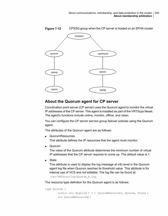
Figure 7-12 CPSSG group when the CP server is hosted on an SFHA cluster
vxcpserv
cpsvip
cpsnic cpsdg
cpsvol
cpsmountquorum
About the Quorum agent for CP serverCoordination point server (CP server) uses the Quorum agent to monitor the virtualIP addresses of the CP server. This agent is installed as part of the VRTScps fileset.The agent's functions include online, monitor, offline, and clean.
You can configure the CP server service group failover policies using the Quorumagent.
The attributes of the Quorum agent are as follows:
■ QuorumResourcesThis attribute defines the IP resources that the agent must monitor.
■ QuorumThe value of the Quorum attribute determines the minimum number of virtualIP addresses that the CP server requires to come up. The default value is 1.
■ StateThis attribute is used to display the log message at info level in the Quorumagent log file when Quorum reaches its threshold value. This attribute is forinternal use of VCS and not editable. The log file can be found at,/var/VRTSvcs/log/Quorum_A.log.
The resource type definition for the Quorum agent is as follows:
type Quorum (
static str ArgList[] = { QuorumResources, Quorum, State }
str QuorumResources[]
240About communications, membership, and data protection in the clusterAbout membership arbitration

int Quorum = 1
)
About the CP server user types and privilegesThe CP server supports the following user types, each with a different access levelprivilege:
■ CP server administrator (admin)
■ CP server operator
Different access level privileges permit the user to issue different commands. If auser is neither a CP server admin nor a CP server operator user, then the user hasguest status and can issue limited commands.
The user types and their access level privileges are assigned to individual usersduring VCS cluster configuration for fencing. During the installation process, youare prompted for a user name, password, and access level privilege (CP serveradmin or CP server operator).
To administer and operate a CP server, there must be at least one CP server admin.
A root user on a CP server is given all the administrator privileges, and theseadministrator privileges can be used to perform all the CP server specific operations.
About secure communication between the VCS cluster and CP serverIn a data center, TCP/IP communication between the VCS cluster (applicationcluster) and CP server must be made secure. The security of the communicationchannel involves encryption, authentication, and authorization.
The CP server node or cluster needs to confirm the authenticity of the VCS clusternodes that communicate with it as a coordination point and only accept requestsfrom known VCS cluster nodes. Requests from unknown clients are rejected asnon-authenticated. Similarly, the fencing framework in VCS cluster must confirmthat authentic users are conducting fencing operations with the CP server.
The secure mode of communication between CP server and VCS cluster is HTTPScommunication.
HTTPS communication: The SSL infrastructure uses the client cluster certificatesand CP server certificates to ensure that communication is secure. The HTTPSmode does not use the broker mechanism to create the authentication servercredentials.
241About communications, membership, and data protection in the clusterAbout membership arbitration

Howsecure communicationworks between the CP serversand the VCS clusters using the HTTPS protocolHTTPS is HTTP communication over SSL/TLS (Secure Sockets Layer/TransportLayer Security). In HTTPS, the communication between client and server is secureusing the Public Key Infrastructure (PKI). HTTPS is an industry standard protocol,which is widely used over the Internet for secure communication. Data encryptedusing private key of an entity, can only be decrypted by using its public key. Acommon trusted entity, such as, the Certification Authority (CA) confirms theidentities of the client and server by signing their certificates. In a CP serverdeployment, both the server and the clients have their own private keys, individualcertificates signed by the common CA, and CA's certificate. CP server uses theSSL implementation from OpenSSL to implement HTTPS for secure communication.
CP server and VCS cluster (application cluster) node communication involve thefollowing entities:
■ vxcpserv for the CP server
■ cpsadm for the VCS cluster node
Communication flow between CP server and VCS cluster nodes with securityconfigured on them is as follows:
■ Initial setup:Identities of CP server and VCS cluster nodes are configured on respectivenodes by the VCS installer.
Note: For secure communication using HTTPS, you do not need to establishtrust between the CP server and the application cluster.
The signed client certificate is used to establish the identity of the client. Oncethe CP server authenticates the client, the client can issue the operationalcommands that are limited to its own cluster.
■ Getting credentials from authentication broker:The cpsadm command tries to get the existing credentials that are present onthe local node. The installer generates these credentials during fencingconfiguration.The vxcpserv process tries to get the existing credentials that are present onthe local node. The installer generates these credentials when it enables security.
■ Communication between CP server and VCS cluster nodes:After the CP server establishes its credential and is up, it becomes ready toreceive data from the clients. After the cpsadm command obtains its credentialsand authenticates CP server credentials, cpsadm connects to the CP server.Data is passed over to the CP server.
242About communications, membership, and data protection in the clusterAbout membership arbitration

■ Validation:On receiving data from a particular VCS cluster node, vxcpserv validates itscredentials. If validation fails, then the connection request data is rejected.
About data protectionMembership arbitration by itself is inadequate for complete data protection becauseit assumes that all systems will either participate in the arbitration or are alreadydown.
Rare situations can arise which must also be protected against. Some examplesare:
■ A system hang causes the kernel to stop processing for a period of time.
■ The system resources were so busy that the heartbeat signal was not sent.
■ A break and resume function is supported by the hardware and executed.Dropping the system to a system controller level with a break command canresult in the heartbeat signal timeout.
In these types of situations, the systems are not actually down, and may return tothe cluster after cluster membership has been recalculated. This could result indata corruption as a system could potentially write to disk before it determines itshould no longer be in the cluster.
Combining membership arbitration with data protection of the shared storageeliminates all of the above possibilities for data corruption.
Data protection fences off (removes access to) the shared data storage from anysystem that is not a current and verified member of the cluster. Access is blockedby the use of SCSI-3 persistent reservations.
About SCSI-3 Persistent ReservationSCSI-3 Persistent Reservation (SCSI-3 PR) supports device access from multiplesystems, or from multiple paths from a single system. At the same time it blocksaccess to the device from other systems, or other paths.
VCS logic determines when to online a service group on a particular system. If theservice group contains a disk group, the disk group is imported as part of the servicegroup being brought online. When using SCSI-3 PR, importing the disk group putsregistration and reservation on the data disks. Only the system that has importedthe storage with SCSI-3 reservation can write to the shared storage. This preventsa system that did not participate in membership arbitration from corrupting theshared storage.
SCSI-3 PR ensures persistent reservations across SCSI bus resets.
243About communications, membership, and data protection in the clusterAbout data protection

Note: Use of SCSI 3 PR protects against all elements in the IT environment thatmight be trying to write illegally to storage, not only VCS related elements.
Membership arbitration combined with data protection is termed I/O fencing.
About I/O fencing configuration filesTable 7-1 lists the I/O fencing configuration files.
Table 7-1 I/O fencing configuration files
DescriptionFile
This file stores the start and stop environment variables for I/O fencing:
■ VXFEN_START—Defines the startup behavior for the I/O fencing module after a systemreboot. Valid values include:1—Indicates that I/O fencing is enabled to start up.0—Indicates that I/O fencing is disabled to start up.
■ VXFEN_STOP—Defines the shutdown behavior for the I/O fencing module during a systemshutdown. Valid values include:1—Indicates that I/O fencing is enabled to shut down.0—Indicates that I/O fencing is disabled to shut down.
The installer sets the value of these variables to 1 at the end of VCS configuration.
If you manually configured VCS, you must make sure to set the values of these environmentvariables to 1.
/etc/default/vxfen
This file includes the coordinator disk group information.
This file is not applicable for server-based fencing and majority-based fencing.
/etc/vxfendg
244About communications, membership, and data protection in the clusterAbout I/O fencing configuration files

Table 7-1 I/O fencing configuration files (continued)
DescriptionFile
This file contains the following parameters:
■ vxfen_mode■ scsi3—For disk-based fencing.■ customized—For server-based fencing.■ disabled—To run the I/O fencing driver but not do any fencing operations.■ majority— For fencing without the use of coordination points.
■ vxfen_mechanismThis parameter is applicable only for server-based fencing. Set the value as cps.
■ scsi3_disk_policy■ dmp—Configure the vxfen module to use DMP devices
The disk policy is dmp by default. If you use iSCSI devices, you must set the disk policyas dmp.
Note: You must use the same SCSI-3 disk policy on all the nodes.
■ List of coordination pointsThis list is required only for server-based fencing configuration.Coordination points in server-based fencing can include coordinator disks, CP servers, orboth. If you use coordinator disks, you must create a coordinator disk group containing theindividual coordinator disks.Refer to the sample file /etc/vxfen.d/vxfenmode_cps for more information on how to specifythe coordination points and multiple IP addresses for each CP server.
■ single_cpThis parameter is applicable for server-based fencing which uses a single highly availableCP server as its coordination point. Also applicable for when you use a coordinator diskgroup with single disk.
■ autoseed_gab_timeoutThis parameter enables GAB automatic seeding of the cluster even when some clusternodes are unavailable.This feature is applicable for I/O fencing in SCSI3 and customized mode.0—Turns the GAB auto-seed feature on. Any value greater than 0 indicates the number ofseconds that GAB must delay before it automatically seeds the cluster.-1—Turns the GAB auto-seed feature off. This setting is the default.
/etc/vxfenmode
245About communications, membership, and data protection in the clusterAbout I/O fencing configuration files

Table 7-1 I/O fencing configuration files (continued)
DescriptionFile
When I/O fencing starts, the vxfen startup script creates this /etc/vxfentab file on each node.The startup script uses the contents of the /etc/vxfendg and /etc/vxfenmode files. Any time asystem is rebooted, the fencing driver reinitializes the vxfentab file with the current list of all thecoordinator points.
Note: The /etc/vxfentab file is a generated file; do not modify this file.
For disk-based I/O fencing, the /etc/vxfentab file on each node contains a list of all paths toeach coordinator disk along with its unique disk identifier. A space separates the path and theunique disk identifier. An example of the /etc/vxfentab file in a disk-based fencing configurationon one node resembles as follows:
■ DMP disk:
/dev/vx/rdmp/rhdisk75 HITACHI%5F1724-100%20%20FAStT%5FDISKS%5F600A0B8000215A5D000006804E795D075/dev/vx/rdmp/rhdisk76 HITACHI%5F1724-100%20%20FAStT%5FDISKS%5F600A0B8000215A5D000006814E795D076/dev/vx/rdmp/rhdisk77 HITACHI%5F1724-100%20%20FAStT%5FDISKS%5F600A0B8000215A5D000006824E795D077
For server-based fencing, the /etc/vxfentab file also includes the security settings information.
For server-based fencing with single CP server, the /etc/vxfentab file also includes the single_cpsettings information.
This file is not applicable for majority-based fencing.
/etc/vxfentab
Examples of VCS operation with I/O fencingThis topic describes the general logic employed by the I/O fencing module alongwith some specific example scenarios. Note that this topic does not apply tomajority-based I/O fencing.
See “About the I/O fencing algorithm” on page 247.
See “Example: Two-system cluster where one system fails” on page 247.
See “Example: Four-system cluster where cluster interconnect fails” on page 248.
246About communications, membership, and data protection in the clusterExamples of VCS operation with I/O fencing

About the I/O fencing algorithmTo ensure the most appropriate behavior is followed in both common and rarecorner case events, the fencing algorithm works as follows:
■ The fencing module is designed to never have systems in more than onesubcluster remain current and valid members of the cluster. In all cases, eitherone subcluster will survive, or in very rare cases, no systems will.
■ The system with the lowest LLT ID in any subcluster of the original cluster racesfor control of the coordinator disks on behalf of the other systems in thatsubcluster.
■ If a system wins the race for the first coordinator disk, that system is given priorityto win the race for the other coordinator disks.Any system that loses a race will delay a short period of time before racing forthe next disk. Under normal circumstances, the winner of the race to the firstcoordinator disk will win all disks.This ensures a clear winner when multiple systems race for the coordinator disk,preventing the case where three or more systems each win the race for onecoordinator disk.
■ If the cluster splits such that one of the subclusters has at least 51% of themembers of the previous stable membership, that subcluster is given priority towin the race.The system in the smaller subcluster(s) delay a short period before beginningthe race.If you use the preferred fencing feature, then the subcluster with the lesser totalweight will delay.See “About preferred fencing” on page 225.This ensures that as many systems as possible will remain running in the cluster.
■ If the vxfen module discovers on startup that the system that has control of thecoordinator disks is not in the current GAB membership, an error messageindicating a possible split brain condition is printed to the console.The administrator must clear this condition manually with the vxfenclearpre
utility.
Example: Two-system cluster where one system failsIn this example, System1 fails, and System0 carries out the I/O fencing operationas follows:
■ The GAB module on System0 determines System1 has failed due to loss ofheartbeat signal reported from LLT.
247About communications, membership, and data protection in the clusterExamples of VCS operation with I/O fencing

■ GAB passes the membership change to the fencing module on each system inthe cluster.The only system that is still running is System0
■ System0 gains control of the coordinator disks by ejecting the key registeredby System1 from each coordinator disk.The ejection takes place one by one, in the order of the coordinator disk’s serialnumber.
■ When the fencing module on System0 successfully controls the coordinatordisks, HAD carries out any associated policy connected with the membershipchange.
■ System1 is blocked access to the shared storage, if this shared storage wasconfigured in a service group that was now taken over by System0 and imported.
Figure 7-13 I/O Fencing example with system failure
system1
Coordinator Disks
system0
Example: Four-system cluster where cluster interconnect failsIn this example, the cluster interconnect fails in such a way as to split the clusterfrom one four-system cluster to two-system clusters. The cluster performsmembership arbitration to ensure that only one subcluster remains.
Due to loss of heartbeat, System0 and System1 both believe System2 and System3are down. System2 and System3 both believe System0 and System1 are down.
248About communications, membership, and data protection in the clusterExamples of VCS operation with I/O fencing

Figure 7-14 Four-system cluster where cluster interconnect fails
System0
SAN Connection LLT Links
System1 System2 System 3
Coordinator Disks
The progression of I/O fencing operations are as follows:
■ LLT on each of the four systems no longer receives heartbeat messages fromthe systems on the other side of the interconnect failure on any of the configuredLLT interfaces for the peer inactive timeout configured time.
■ LLT on each system passes to GAB that it has noticed a membership change.Specifically:
■ LLT on System0 passes to GAB that it no longer sees System2 and System3
■ LLT on System1 passes to GAB that it no longer sees System2 and System3
■ LLT on System2 passes to GAB that it no longer sees System0 and System1
■ LLT on System3 passes to GAB that it no longer sees System0 and System1
■ After LLT informs GAB of a heartbeat loss, the systems that are remaining doa "GAB Stable Timeout” (5 seconds). In this example:
■ System0 and System1 agree that both of them do not see System2 andSystem3
■ System2 and System3 agree that both of them do not see System0 andSystem1
■ GAB marks the system as DOWN, and excludes the system from the clustermembership. In this example:
■ GAB on System0 and System1 mark System2 and System3 as DOWN andexcludes them from cluster membership.
■ GAB on System2 and System3 mark System0 and System1 as DOWN andexcludes them from cluster membership.
249About communications, membership, and data protection in the clusterExamples of VCS operation with I/O fencing

■ GAB on each of the four systems passes the membership change to the vxfendriver for membership arbitration. Each subcluster races for control of thecoordinator disks. In this example:
■ System0 has the lower LLT ID, and races on behalf of itself and System1.
■ System2 has the lower LLT ID, and races on behalf of itself and System3.
■ GAB on each of the four systems also passes the membership change to HAD.HAD waits for the result of the membership arbitration from the fencing modulebefore taking any further action.
■ If System0 is not able to reach a majority of the coordination points, then theVxFEN driver will initiate a racer re-election from System0 to System1 andSystem1 will initiate the race for the coordination points.
■ Assume System0 wins the race for the coordinator disks, and ejects theregistration keys of System2 and System3 off the disks. The result is as follows:
■ System0 wins the race for the coordinator disk. The fencing module onSystem0 sends a WON_RACE to all other fencing modules in the currentcluster, in this case System0 and System1. On receiving a WON_RACE,the fencing module on each system in turn communicates success to HAD.System0 and System1 remain valid and current members of the cluster.
■ If System0 dies before it sends a WON_RACE to System1, then VxFEN willinitiate a racer re-election from System0 to System1 and System1 will initiatethe race for the coordination points.System1 on winning a majority of the coordination points remains valid andcurrent member of the cluster and the fencing module on System1 in turncommunicates success to HAD.
■ System2 loses the race for control of the coordinator disks and the fencingmodule on System 2 sends a LOST_RACE message. The fencing moduleon System2 calls a kernel panic and the system restarts.
■ System3 sees another membership change from the kernel panic of System2.Because that was the system that was racing for control of the coordinatordisks in this subcluster, System3 also panics.
■ HAD carries out any associated policy or recovery actions based on themembership change.
■ System2 and System3 are blocked access to the shared storage (if the sharedstorage was part of a service group that is now taken over by System0 or System1).
■ To rejoin System2 and System3 to the cluster, the administrator must do thefollowing:
250About communications, membership, and data protection in the clusterExamples of VCS operation with I/O fencing
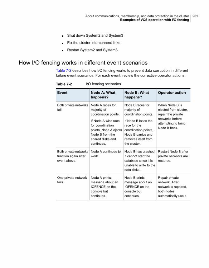
■ Shut down System2 and System3
■ Fix the cluster interconnect links
■ Restart System2 and System3
How I/O fencing works in different event scenariosTable 7-2 describes how I/O fencing works to prevent data corruption in differentfailure event scenarios. For each event, review the corrective operator actions.
Table 7-2 I/O fencing scenarios
Operator actionNode B: Whathappens?
Node A: Whathappens?
Event
When Node B isejected from cluster,repair the privatenetworks beforeattempting to bringNode B back.
Node B races formajority ofcoordination points.
If Node B loses therace for thecoordination points,Node B panics andremoves itself fromthe cluster.
Node A races formajority ofcoordination points.
If Node A wins racefor coordinationpoints, Node A ejectsNode B from theshared disks andcontinues.
Both private networksfail.
Restart Node B afterprivate networks arerestored.
Node B has crashed.It cannot start thedatabase since it isunable to write to thedata disks.
Node A continues towork.
Both private networksfunction again afterevent above.
Repair privatenetwork. Afternetwork is repaired,both nodesautomatically use it.
Node B printsmessage about anIOFENCE on theconsole butcontinues.
Node A printsmessage about anIOFENCE on theconsole butcontinues.
One private networkfails.
251About communications, membership, and data protection in the clusterExamples of VCS operation with I/O fencing
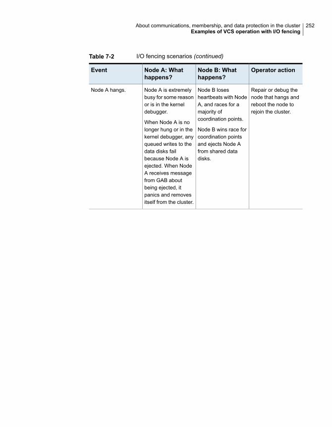
Table 7-2 I/O fencing scenarios (continued)
Operator actionNode B: Whathappens?
Node A: Whathappens?
Event
Repair or debug thenode that hangs andreboot the node torejoin the cluster.
Node B losesheartbeats with NodeA, and races for amajority ofcoordination points.
Node B wins race forcoordination pointsand ejects Node Afrom shared datadisks.
Node A is extremelybusy for some reasonor is in the kerneldebugger.
When Node A is nolonger hung or in thekernel debugger, anyqueued writes to thedata disks failbecause Node A isejected. When NodeA receives messagefrom GAB aboutbeing ejected, itpanics and removesitself from the cluster.
Node A hangs.
252About communications, membership, and data protection in the clusterExamples of VCS operation with I/O fencing

Table 7-2 I/O fencing scenarios (continued)
Operator actionNode B: Whathappens?
Node A: Whathappens?
Event
Resolve preexistingsplit-brain condition.
See “Fencing startupreports preexistingsplit-brain”on page 617.
Node B restarts andI/O fencing driver(vxfen) detects NodeA is registered withcoordination points.The driver does notsee Node A listed asmember of clusterbecause privatenetworks are down.This causes the I/Ofencing device driverto prevent Node Bfrom joining thecluster. Node Bconsole displays:
Potentially apreexistingsplit brain.Dropping outof the cluster.Refer to theuserdocumentationfor stepsrequiredto clearpreexistingsplit brain.
Node A restarts andI/O fencing driver(vxfen) detects NodeB is registered withcoordination points.The driver does notsee Node B listed asmember of clusterbecause privatenetworks are down.This causes the I/Ofencing device driverto prevent Node Afrom joining thecluster. Node Aconsole displays:
Potentially apreexistingsplit brain.Dropping outof the cluster.Refer to theuserdocumentationfor stepsrequiredto clearpreexistingsplit brain.
Nodes A and B andprivate networks losepower. Coordinationpoints and data disksretain power.
Power returns tonodes and theyrestart, but privatenetworks still have nopower.
253About communications, membership, and data protection in the clusterExamples of VCS operation with I/O fencing
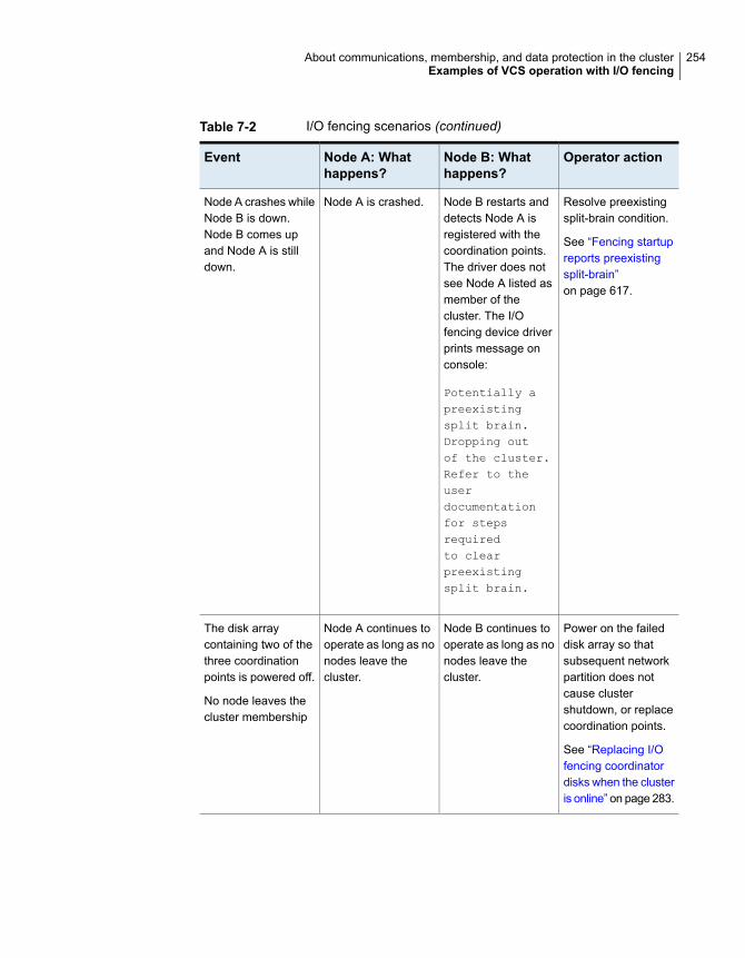
Table 7-2 I/O fencing scenarios (continued)
Operator actionNode B: Whathappens?
Node A: Whathappens?
Event
Resolve preexistingsplit-brain condition.
See “Fencing startupreports preexistingsplit-brain”on page 617.
Node B restarts anddetects Node A isregistered with thecoordination points.The driver does notsee Node A listed asmember of thecluster. The I/Ofencing device driverprints message onconsole:
Potentially apreexistingsplit brain.Dropping outof the cluster.Refer to theuserdocumentationfor stepsrequiredto clearpreexistingsplit brain.
Node A is crashed.Node A crashes whileNode B is down.Node B comes upand Node A is stilldown.
Power on the faileddisk array so thatsubsequent networkpartition does notcause clustershutdown, or replacecoordination points.
See “Replacing I/Ofencing coordinatordisks when the clusteris online” on page 283.
Node B continues tooperate as long as nonodes leave thecluster.
Node A continues tooperate as long as nonodes leave thecluster.
The disk arraycontaining two of thethree coordinationpoints is powered off.
No node leaves thecluster membership
254About communications, membership, and data protection in the clusterExamples of VCS operation with I/O fencing

Table 7-2 I/O fencing scenarios (continued)
Operator actionNode B: Whathappens?
Node A: Whathappens?
Event
Power on the faileddisk array so thatsubsequent networkpartition does notcause clustershutdown, or replacecoordination points.
See “Replacing I/Ofencing coordinatordisks when the clusteris online” on page 283.
Node B has left thecluster.
Node A continues tooperate in the cluster.
The disk arraycontaining two of thethree coordinationpoints is powered off.
Node B gracefullyleaves the cluster andthe disk array is stillpowered off. Leavinggracefully implies aclean shutdown sothat vxfen is properlyunconfigured.
Power on the faileddisk array and restartI/O fencing driver toenable Node A toregister with allcoordination points,or replacecoordination points.
See “Replacingdefective disks whenthe cluster is offline”on page 620.
Node B has leftcluster due to crashor network partition.
Node A races for amajority ofcoordination points.Node A fails becauseonly one of the threecoordination points isavailable. Node Apanics and removesitself from the cluster.
The disk arraycontaining two of thethree coordinationpoints is powered off.
Node B abruptlycrashes or a networkpartition occursbetween node A andnode B, and the diskarray is still poweredoff.
About cluster membership and data protectionwithout I/O fencing
Proper seeding of the cluster and the use of low priority heartbeat clusterinterconnect links are best practices with or without the use of I/O fencing. Bestpractice also recommends multiple cluster interconnect links between systems inthe cluster. This allows GAB to differentiate between:
■ A loss of all heartbeat links simultaneously, which is interpreted as a systemfailure. In this case, depending on failover configuration, HAD may attempt torestart the services that were running on that system on another system.
■ A loss of all heartbeat links over time, which is interpreted as an interconnectfailure. In this case, the assumption is made that there is a high probability that
255About communications, membership, and data protection in the clusterAbout cluster membership and data protection without I/O fencing

the system is not down, and HAD does not attempt to restart the services onanother system.
In order for this differentiation to have meaning, it is important to ensure the clusterinterconnect links do not have a single point of failure, such as a network switch orEthernet card.
About jeopardyIn all cases, when LLT on a system no longer receives heartbeat messages fromanother system on any of the configured LLT interfaces, GAB reports a change inmembership.
When a system has only one interconnect link remaining to the cluster, GAB canno longer reliably discriminate between loss of a system and loss of the network.The reliability of the system’s membership is considered at risk. A specialmembership category takes effect in this situation, called a jeopardy membership.This provides the best possible split-brain protection without membership arbitrationand SCSI-3 capable devices.
When a system is placed in jeopardy membership status, two actions occur if thesystem loses the last interconnect link:
■ VCS places service groups running on the system in autodisabled state. Aservice group in autodisabled state may failover on a resource or group fault,but cannot fail over on a system fault until the autodisabled flag is manuallycleared by the administrator.
■ VCS operates the system as a single system cluster. Other systems in thecluster are partitioned off in a separate cluster membership.
About Daemon Down Node Alive (DDNA)Daemon Down Node Alive (DDNA) is a condition in which the VCS high availabilitydaemon (HAD) on a node fails, but the node is running. When HAD fails, thehashadow process tries to bring HAD up again. If the hashadow process succeedsin bringing HAD up, the system leaves the DDNA membership and joins the regularmembership.
In a DDNA condition, VCS does not have information about the state of servicegroups on the node. So, VCS places all service groups that were online on theaffected node in the autodisabled state. The service groups that were online on thenode cannot fail over.
Manual intervention is required to enable failover of autodisabled service groups.The administrator must release the resources running on the affected node, clearresource faults, and bring the service groups online on another node.
256About communications, membership, and data protection in the clusterAbout cluster membership and data protection without I/O fencing

You can use the GAB registration monitoring feature to detect DDNA conditions.
See “About GAB client registration monitoring” on page 552.
Examples of VCS operation without I/O fencingThe following scenarios describe events, and how VCS responds, in a clusterwithout I/O fencing.
See “Example: Four-system cluster without a low priority link” on page 257.
See “Example: Four-system cluster with low priority link” on page 259.
Example: Four-system cluster without a low priority linkConsider a four-system cluster that has two private cluster interconnect heartbeatlinks. The cluster does not have any low priority link.
Public Network
Node 0 Node 1 Node 2 Node 3
Regular membership: 0, 1, 2, 3
Cluster interconnect link failureIn this example, a link to System2 fails, leaving System2 with only one clusterinterconnect link remaining.
257About communications, membership, and data protection in the clusterExamples of VCS operation without I/O fencing

System0 System1 System2 System3
Public Network
Membership: 0,1, 2, 3
Jeopardy membership: 2
The cluster is reconfigured. Systems 0, 1, and 3 are in the regular membership andSystem2 in a jeopardy membership. Service groups on System2 are autodisabled.All normal cluster operations continue, including normal failover of service groupsdue to resource fault.
Cluster interconnect link failure followed by system failureIn this example, the link to System2 fails, and System2 is put in the jeopardymembership. Subsequently, System2 fails due to a power fault.
Public Network
System0 System1 System2 System3
Regular membership: 0,1,3 (withknown previous jeopardymembership for System2)
Systems 0, 1, and 3 recognize that System2 has faulted. The cluster is reformed.Systems 0, 1, and 3 are in a regular membership. When System2 went into jeopardymembership, service groups running on System2 were autodisabled. Even thoughthe system is now completely failed, no other system can assume ownership ofthese service groups unless the system administrator manually clears theAutoDisabled flag on the service groups that were running on System2.
However, after the flag is cleared, these service groups can be manually broughtonline on other systems in the cluster.
258About communications, membership, and data protection in the clusterExamples of VCS operation without I/O fencing

All high priority cluster interconnect links failIn this example, all high priority links to System2 fail. This can occur two ways:
System0 System1 System2 System3
Public Network
Regular membership: 0,1, 3 (Cluster 1)
Regular membership: 2 (Cluster 2)
■ Both links to System2 fail at the same timeSystem2 was never in jeopardy membership. Without a low priority link, thecluster splits into two subclusters, where System0, 1 and 3 are in one subcluster,and System2 is in another. This is a split brain scenario.
■ Both links to System2 fail at different timesSystem2 was in a jeopardy membership when the second link failed, andtherefore the service groups that were online on System2 were autodisabled.No other system can online these service groups without administratorintervention.Systems 0, 1 and 3 form a mini-cluster. System2 forms another single- systemmini-cluster. All service groups that were present on systems 0, 1 and 3 areautodisabled on System2.
Example: Four-system cluster with low priority linkConsider a four-system cluster that has two private cluster interconnect heartbeatlinks, and one public low priority link.
259About communications, membership, and data protection in the clusterExamples of VCS operation without I/O fencing

System0 System1 System2 System3
Public Network
Regular membership: 0,1,2,3Cluster status on private networksHeartbeat only on public network
Cluster interconnect link failureIn this example, a link to System2 fails, leaving System2 with one cluster interconnectlink and the low priority link remaining.
System0 System1 System2 System3
Public Network
Regular membership: 0,1,2,3
No jeopardy
Other systems send all cluster status traffic to System2 over the remaining privatelink and use both private links for traffic between themselves. The low priority linkcontinues carrying the heartbeat signal only. No jeopardy condition is in effectbecause two links remain to determine system failure.
Cluster interconnect link failure followed by system failureIn this example, the link to System2 fails. Because there is a low priority heartbeatlink, System2 is not put in the jeopardy membership. Subsequently, System2 failsdue to a power fault.
260About communications, membership, and data protection in the clusterExamples of VCS operation without I/O fencing

Public Network
System0 System1 System2 System3
Regular membership: 0,1,3
Systems 0, 1, and 3 recognize that System2 has faulted. The cluster is reformed.Systems 0, 1, and 3 are in a regular membership. The service groups on System2that are configured for failover on system fault are attempted to be brought onlineon another target system, if one exists.
All high priority cluster interconnect links failIn this example, both high priority cluster interconnect links to System2 fail, leavingSystem2 with only the low priority link remaining.
Cluster status communication is now routed over the low priority link to System2.System2 is placed in a jeopardy membership. The service groups on System2 areautodisabled, and the service group attribute AutoFailOver is set to 0, meaning theservice group will not fail over on a system fault.
System0 System1 System2 System3
Public Network
Regular membership: 0,1,3
Jeopardy membership: 2
When a cluster interconnect link is re-established, all cluster status communicationsrevert back to the cluster interconnect and the low priority link returns to sendingheartbeat signal only. At this point, System2 is placed back in regular clustermembership.
261About communications, membership, and data protection in the clusterExamples of VCS operation without I/O fencing

Summary of best practices for clustercommunications
Veritas Technologies recommends the following best practices for clustercommunications to best support proper cluster membership and data protection:
■ Properly seed the cluster by requiring all systems, and not just a subset ofsystems, to be present in the GAB membership before the cluster willautomatically seed.If every system is not present, manual intervention by the administrator musteliminate the possibility of a split brain condition before manually seeding thecluster.
■ Configure multiple independent communication network links between clustersystems.Networks should not have a single point of failure, such as a shared switch orEthernet card.
■ Low-priority LLT links in clusters with or without I/O fencing is recommended.In clusters without I/O fencing, this is critical.
Note: An exception to this is if the cluster uses fencing along with Cluster FileSystems (CFS) or Oracle Real Application Clusters (RAC).
The reason for this is that low priority links are usually shared public networklinks. In the case where the main cluster interconnects fail, and the low prioritylink was the only remaining link, large amounts of data would be moved to thelow priority link. This would potentially slow down the public network tounacceptable performance. Without a low priority link configured, membershiparbitration would go into effect in this case, and some systems may be takendown, but the remaining systems would continue to run without impact to thepublic network.It is not recommended to have a cluster with CFS or RAC without I/O fencingconfigured.
■ Disable the console-abort sequenceMost UNIX systems provide a console-abort sequence that enables theadministrator to halt and continue the processor. Continuing operations afterthe processor has stopped may corrupt data and is therefore unsupported byVCS.When a system is halted with the abort sequence, it stops producing heartbeats.The other systems in the cluster consider the system failed and take over itsservices. If the system is later enabled with another console sequence, it
262About communications, membership, and data protection in the clusterSummary of best practices for cluster communications

continues writing to shared storage as before, even though its applications havebeen restarted on other systems.Veritas Technologies recommends disabling the console-abort sequence orcreating an alias to force the go command to perform a restart on systems notrunning I/O fencing.
■ Veritas Technologies recommends at least three coordination points to configureI/O fencing. You can use coordinator disks, CP servers, or a combination ofboth.Select the smallest possible LUNs for use as coordinator disks. No more thanthree coordinator disks are needed in any configuration.
■ Do not reconnect the cluster interconnect after a network partition without shuttingdown one side of the split cluster.A common example of this happens during testing, where the administrator maydisconnect the cluster interconnect and create a network partition. Dependingon when the interconnect cables are reconnected, unexpected behavior canoccur.
263About communications, membership, and data protection in the clusterSummary of best practices for cluster communications

Administering I/O fencingThis chapter includes the following topics:
■ About administering I/O fencing
■ About the vxfentsthdw utility
■ About the vxfenadm utility
■ About the vxfenclearpre utility
■ About the vxfenswap utility
■ About administering the coordination point server
■ About migrating between disk-based and server-based fencing configurations
■ Enabling or disabling the preferred fencing policy
■ About I/O fencing log files
About administering I/O fencingThe I/O fencing feature provides the following utilities that are available through theVRTSvxfen fileset:
Tests SCSI-3 functionality of the disks for I/O fencing
See “About the vxfentsthdw utility” on page 265.
vxfentsthdw
Configures and unconfigures I/O fencing
Lists the coordination points used by the vxfen driver.
vxfenconfig
8Chapter

Displays information on I/O fencing operations and managesSCSI-3 disk registrations and reservations for I/O fencing
See “About the vxfenadm utility” on page 274.
vxfenadm
Removes SCSI-3 registrations and reservations from disks
See “About the vxfenclearpre utility” on page 279.
vxfenclearpre
Replaces coordination points without stopping I/O fencing
See “About the vxfenswap utility” on page 282.
vxfenswap
Generates the list of paths of disks in the disk group. This utilityrequires that Veritas Volume Manager (VxVM) is installed andconfigured.
vxfendisk
The I/O fencing commands reside in the /opt/VRTS/bin folder. Make sure you addedthis folder path to the PATH environment variable.
Refer to the corresponding manual page for more information on the commands.
About the vxfentsthdw utilityYou can use the vxfentsthdw utility to verify that shared storage arrays to be usedfor data support SCSI-3 persistent reservations and I/O fencing. During the I/Ofencing configuration, the testing utility is used to test a single disk. The utility hasother options that may be more suitable for testing storage devices in otherconfigurations. You also need to test coordinator disk groups.
See the Cluster Server Installation Guide to set up I/O fencing.
The utility, which you can run from one system in the cluster, tests the storage usedfor data by setting and verifying SCSI-3 registrations on the disk or disks you specify,setting and verifying persistent reservations on the disks, writing data to the disksand reading it, and removing the registrations from the disks.
Refer also to the vxfentsthdw(1M) manual page.
General guidelines for using the vxfentsthdw utilityReview the following guidelines to use the vxfentsthdw utility:
■ The utility requires two systems connected to the shared storage.
Caution: The tests overwrite and destroy data on the disks, unless you use the-r option.
265Administering I/O fencingAbout the vxfentsthdw utility

■ The two nodes must have SSH (default) or rsh communication. If you use rsh,launch the vxfentsthdw utility with the -n option.After completing the testing process, you can remove permissions forcommunication and restore public network connections.
■ To ensure both systems are connected to the same disk during the testing, youcan use the vxfenadm -i diskpath command to verify a disk’s serial number.See “Verifying that the nodes see the same disk” on page 278.
■ For disk arrays with many disks, use the -m option to sample a few disks beforecreating a disk group and using the -g option to test them all.
■ The utility indicates a disk can be used for I/O fencing with a messageresembling:
The disk /dev/rhdisk75 is ready to be configured for
I/O Fencing on node sys1
If the utility does not show a message stating a disk is ready, verification hasfailed.
■ The -o option overrides disk size-related errors and the utility proceeds withother tests, however, the disk may not setup correctly as the size may be smallerthan the supported size. The supported disk size for data disks is 256 MB andfor coordinator disks is 128 MB.
■ If the disk you intend to test has existing SCSI-3 registration keys, the test issuesa warning before proceeding.
About the vxfentsthdw command optionsTable 8-1 describes the methods that the utility provides to test storage devices.
Table 8-1 vxfentsthdw options
When to useDescriptionvxfentsthdwoption
Use when rsh is used forcommunication.
Utility uses rsh forcommunication.
-n
Use during non-destructivetesting.
See “Performing non-destructivetesting on the disks using the -roption” on page 270.
Non-destructive testing. Testingof the disks for SCSI-3 persistentreservations occurs in anon-destructive way; that is,there is only testing for reads, notwrites. Can be used with -m, -f,or -g options.
-r
266Administering I/O fencingAbout the vxfentsthdw utility

Table 8-1 vxfentsthdw options (continued)
When to useDescriptionvxfentsthdwoption
When you want to perform TURtesting.
Testing of the return value ofSCSI TEST UNIT (TUR)command under SCSI-3reservations. A warning is printedon failure of TUR testing.
-t
By default, the vxfentsthdwscript picks up the DMP paths fordisks in the disk group. If youwant the script to use the rawpaths for disks in the disk group,use the -w option.
Use Dynamic Multi-Pathing(DMP) devices.
Can be used with -c or -goptions.
-d
With the -w option, thevxfentsthdw script picks theoperating system paths for disksin the disk group. By default, thescript uses the -d option to pickup the DMP paths for disks in thedisk group.
Use raw devices.
Can be used with -c or -goptions.
-w
For testing disks in coordinatordisk group.
See “Testing the coordinator diskgroup using the -c option ofvxfentsthdw” on page 268.
Utility tests the coordinator diskgroup prompting for systems anddevices, and reporting successor failure.
-c
For testing a few disks or forsampling disks in larger arrays.
See “Testing the shared disksusing the vxfentsthdw -m option”on page 270.
Utility runs manually, ininteractive mode, prompting forsystems and devices, andreporting success or failure.
Can be used with -r and -toptions. -m is the default option.
-m
For testing several disks.
See “Testing the shared diskslisted in a file using thevxfentsthdw -f option”on page 272.
Utility tests system and devicecombinations listed in a text file.
Can be used with -r and -toptions.
-f filename
267Administering I/O fencingAbout the vxfentsthdw utility

Table 8-1 vxfentsthdw options (continued)
When to useDescriptionvxfentsthdwoption
For testing many disks andarrays of disks. Disk groups maybe temporarily created for testingpurposes and destroyed(ungrouped) after testing.
See “Testing all the disks in adisk group using the vxfentsthdw-g option” on page 272.
Utility tests all disk devices in aspecified disk group.
Can be used with -r and -toptions.
-g disk_group
For testing SCSI-3 Reservationcompliance of disks, but,overrides disk size-related errors.
See “Testing disks with thevxfentsthdw -o option”on page 273.
Utility overrrides disk size-relatederrors.
-o
Testing the coordinator disk group using the -c option of vxfentsthdwUse the vxfentsthdw utility to verify disks are configured to support I/O fencing. Inthis procedure, the vxfentsthdw utility tests the three disks, one disk at a time fromeach node.
The procedure in this section uses the following disks for example:
■ From the node sys1, the disks are seen as /dev/rhdisk75, /dev/rhdisk76,and /dev/rhdisk77.
■ From the node sys2, the same disks are seen as /dev/rhdisk80,/dev/rhdisk81, and /dev/rhdisk82.
Note: To test the coordinator disk group using the vxfentsthdw utility, the utilityrequires that the coordinator disk group, vxfencoorddg, be accessible from twonodes.
268Administering I/O fencingAbout the vxfentsthdw utility

To test the coordinator disk group using vxfentsthdw -c
1 Use the vxfentsthdw command with the -c option. For example:
# vxfentsthdw -c vxfencoorddg
2 Enter the nodes you are using to test the coordinator disks:
Enter the first node of the cluster: sys1
Enter the second node of the cluster: sys2
3 Review the output of the testing process for both nodes for all disks in thecoordinator disk group. Each disk should display output that resembles:
ALL tests on the disk /dev/rhdisk75 have PASSED.
The disk is now ready to be configured for I/O Fencing on node
sys1 as a COORDINATOR DISK.
ALL tests on the disk /dev/rhdisk80 have PASSED.
The disk is now ready to be configured for I/O Fencing on node
sys2 as a COORDINATOR DISK.
4 After you test all disks in the disk group, the vxfencoorddg disk group is readyfor use.
Removing and replacing a failed diskIf a disk in the coordinator disk group fails verification, remove the failed disk orLUN from the vxfencoorddg disk group, replace it with another, and retest the diskgroup.
269Administering I/O fencingAbout the vxfentsthdw utility
To remove and replace a failed disk
1 Use the vxdiskadm utility to remove the failed disk from the disk group.
Refer to the Storage Foundation Administrator’s Guide.
2 Add a new disk to the node, initialize it, and add it to the coordinator disk group.
See the Cluster Server Installation Guide for instructions to initialize disks forI/O fencing and to set up coordinator disk groups.
If necessary, start the disk group.
See the Storage Foundation Administrator’s Guide for instructions to start thedisk group.
3 Retest the disk group.
See “Testing the coordinator disk group using the -c option of vxfentsthdw”on page 268.
Performing non-destructive testing on the disks using the -r optionYou can perform non-destructive testing on the disk devices when you want topreserve the data.
To perform non-destructive testing on disks
◆ To test disk devices containing data you want to preserve, you can use the -r
option with the -m, -f, or -g options.
For example, to use the -m option and the -r option, you can run the utility asfollows:
# vxfentsthdw -rm
When invoked with the -r option, the utility does not use tests that write to thedisks. Therefore, it does not test the disks for all of the usual conditions of use.
Testing the shared disks using the vxfentsthdw -m optionReview the procedure to test the shared disks. By default, the utility uses the -m
option.
This procedure uses the /dev/rhdisk75 disk in the steps.
If the utility does not show a message stating a disk is ready, verification has failed.Failure of verification can be the result of an improperly configured disk array. Itcan also be caused by a bad disk.
270Administering I/O fencingAbout the vxfentsthdw utility

If the failure is due to a bad disk, remove and replace it. The vxfentsthdw utilityindicates a disk can be used for I/O fencing with a message resembling:
The disk /dev/rhdisk75 is ready to be configured for
I/O Fencing on node sys1
Note: For A/P arrays, run the vxfentsthdw command only on active enabled paths.
To test disks using the vxfentsthdw script
1 Make sure system-to-system communication is functioning properly.
2 From one node, start the utility.
# vxfentsthdw [-n]
3 After reviewing the overview and warning that the tests overwrite data on thedisks, confirm to continue the process and enter the node names.
******** WARNING!!!!!!!! ********
THIS UTILITY WILL DESTROY THE DATA ON THE DISK!!
Do you still want to continue : [y/n] (default: n) y
Enter the first node of the cluster: sys1
Enter the second node of the cluster: sys2
4 Enter the names of the disks you are checking. For each node, the disk maybe known by the same name:
Enter the disk name to be checked for SCSI-3 PGR on node
sys1 in the format: /dev/rhdiskx
/dev/rhdisk75
Enter the disk name to be checked for SCSI-3 PGR on node
sys2 in the format: /dev/rhdiskx
Make sure it's the same disk as seen by nodes sys1 and sys2
/dev/rhdisk75
If the serial numbers of the disks are not identical, then the test terminates.
5 Review the output as the utility performs the checks and report its activities.
271Administering I/O fencingAbout the vxfentsthdw utility

6 If a disk is ready for I/O fencing on each node, the utility reports success:
ALL tests on the disk /dev/rhdisk75 have PASSED
The disk is now ready to be configured for I/O Fencing on node
sys1
...
Removing test keys and temporary files, if any ...
.
.
7 Run the vxfentsthdw utility for each disk you intend to verify.
Testing the shared disks listed in a file using the vxfentsthdw -f optionUse the -f option to test disks that are listed in a text file. Review the followingexample procedure.
To test the shared disks listed in a file
1 Create a text file disks_test to test two disks shared by systems sys1 andsys2 that might resemble:
sys1 /dev/rhdisk75 sys2 /dev/rhdisk77
sys1 /dev/rhdisk76 sys2 /dev/rhdisk78
where the first disk is listed in the first line and is seen by sys1 as/dev/rhdisk75 and by sys2 as /dev/rhdisk77. The other disk, in the secondline, is seen as /dev/rhdisk76 from sys1 and /dev/rhdisk78 from sys2.Typically, the list of disks could be extensive.
2 To test the disks, enter the following command:
# vxfentsthdw -f disks_test
The utility reports the test results one disk at a time, just as for the -m option.
Testing all the disks in a disk group using the vxfentsthdw -g optionUse the -g option to test all disks within a disk group. For example, you create atemporary disk group consisting of all disks in a disk array and test the group.
Note: Do not import the test disk group as shared; that is, do not use the -s optionwith the vxdg import command.
After testing, destroy the disk group and put the disks into disk groups as you need.
272Administering I/O fencingAbout the vxfentsthdw utility

To test all the disks in a disk group
1 Create a disk group for the disks that you want to test.
2 Enter the following command to test the disk group test_disks_dg:
# vxfentsthdw -g test_disks_dg
The utility reports the test results one disk at a time.
Testing a disk with existing keysIf the utility detects that a coordinator disk has existing keys, you see a messagethat resembles:
There are Veritas I/O fencing keys on the disk. Please make sure
that I/O fencing is shut down on all nodes of the cluster before
continuing.
******** WARNING!!!!!!!! ********
THIS SCRIPT CAN ONLY BE USED IF THERE ARE NO OTHER ACTIVE NODES
IN THE CLUSTER! VERIFY ALL OTHER NODES ARE POWERED OFF OR
INCAPABLE OF ACCESSING SHARED STORAGE.
If this is not the case, data corruption will result.
Do you still want to continue : [y/n] (default: n) y
The utility prompts you with a warning before proceeding. You may continue aslong as I/O fencing is not yet configured.
Testing disks with the vxfentsthdw -o optionUse the -o option to check for SCSI-3 reservation or registration compliance butnot to test the disk size requirements.
Note that you can override a disk size-related error by using the -o flag. The -o
flag lets the utility continue with tests related to SCSI-3 reservations, registrations,and other tests. However, the disks may not set up correctly as the disk size maybe below the supported size for coordinator or data disks.
You can use the -o option with all the available vxfentsthdw options when youencounter size-related errors.
273Administering I/O fencingAbout the vxfentsthdw utility

About the vxfenadm utilityAdministrators can use the vxfenadm command to troubleshoot and test fencingconfigurations.
The command’s options for use by administrators are as follows:
read the keys on a disk and display the keys in numeric, character, andnode format
Note: The -g and -G options are deprecated. Use the -s option.
-s
read SCSI inquiry information from device-i
register with disks-m
make a reservation with disks-n
remove registrations made by other systems-p
read reservations-r
remove registrations-x
Refer to the vxfenadm(1M) manual page for a complete list of the command options.
About the I/O fencing registration key formatThe keys that the vxfen driver registers on the data disks and the coordinator disksconsist of eight bytes. The key format is different for the coordinator disks and datadisks.
The key format of the coordinator disks is as follows:
76543210Byte
nID 0xnID 0xcID 0xcID 0xcID 0xcID 0xFVValue
where:
■ VF is the unique identifier that carves out a namespace for the keys (consumestwo bytes)
■ cID 0x is the LLT cluster ID in hexadecimal (consumes four bytes)
■ nID 0x is the LLT node ID in hexadecimal (consumes two bytes)
The vxfen driver uses this key format in both sybase mode of I/O fencing.
274Administering I/O fencingAbout the vxfenadm utility

The key format of the data disks that are configured as failover disk groups underVCS is as follows:
76543210Byte
SCVA+nIDValue
where nID is the LLT node ID
For example: If the node ID is 1, then the first byte has the value as B (‘A’ + 1 = B).
The key format of the data disks configured as parallel disk groups under ClusterVolume Manager (CVM) is as follows:
76543210Byte
DGcountDGcountDGcountDGcountRGPA+nIDValue
where DGcount is the count of disk groups in the configuration (consumes fourbytes).
By default, CVM uses a unique fencing key for each disk group. However, somearrays have a restriction on the total number of unique keys that can be registered.In such cases, you can use the same_key_for_alldgs tunable parameter to changethe default behavior. The default value of the parameter is off. If your configurationhits the storage array limit on total number of unique keys, you can change thevalue to on using the vxdefault command as follows:
# vxdefault set same_key_for_alldgs on
# vxdefault list
KEYWORD CURRENT-VALUE DEFAULT-VALUE
...
same_key_for_alldgs on off
...
If the tunable is changed to on, all subsequent keys that the CVM generates ondisk group imports or creates have '0000' as their last four bytes (DGcount is 0).You must deport and re-import all the disk groups that are already imported for thechanged value of the same_key_for_alldgs tunable to take effect.
Displaying the I/O fencing registration keysYou can display the keys that are currently assigned to the disks using the vxfenadm
command.
275Administering I/O fencingAbout the vxfenadm utility

The variables such as disk_7, disk_8, and disk_9 in the following procedurerepresent the disk names in your setup.
To display the I/O fencing registration keys
1 To display the key for the disks, run the following command:
# vxfenadm -s disk_name
For example:
■ To display the key for the coordinator disk /dev/rhdisk75 from the systemwith node ID 1, enter the following command:
# vxfenadm -s /dev/rhdisk75
key[1]:
[Numeric Format]: 86,70,68,69,69,68,48,48
[Character Format]: VFDEED00
* [Node Format]: Cluster ID: 57069 Node ID: 0 Node Name: sys1
The -s option of vxfenadm displays all eight bytes of a key value in threeformats. In the numeric format,
■ The first two bytes, represent the identifier VF, contains the ASCII value86, 70.
■ The next four bytes contain the ASCII value of the cluster ID 57069encoded in hex (0xDEED) which are 68, 69, 69, 68.
■ The remaining bytes contain the ASCII value of the node ID 0 (0x00)which are 48, 48. Node ID 1 would be 01 and node ID 10 would be 0A.
An asterisk before the Node Format indicates that the vxfenadm commandis run from the node of a cluster where LLT is configured and is running.
■ To display the keys on a CVM parallel disk group:
# vxfenadm -s /dev/vx/rdmp/disk_7
Reading SCSI Registration Keys...
Device Name: /dev/vx/rdmp/disk_7
Total Number Of Keys: 1
key[0]:
[Numeric Format]: 66,80,71,82,48,48,48,49
[Character Format]: BPGR0001
[Node Format]: Cluster ID: unknown Node ID: 1 Node Name: sys2
■ To display the keys on a Cluster Server (VCS) failover disk group:
276Administering I/O fencingAbout the vxfenadm utility

# vxfenadm -s /dev/vx/rdmp/disk_8
Reading SCSI Registration Keys...
Device Name: /dev/vx/rdmp/disk_8
Total Number Of Keys: 1
key[0]:
[Numeric Format]: 65,86,67,83,0,0,0,0
[Character Format]: AVCS
[Node Format]: Cluster ID: unknown Node ID: 0 Node Name: sys1
2 To display the keys that are registered in all the disks specified in a disk file:
# vxfenadm -s all -f disk_filename
For example:
To display all the keys on coordinator disks:
# vxfenadm -s all -f /etc/vxfentab
Device Name: /dev/vx/rdmp/disk_9
Total Number Of Keys: 2
key[0]:
[Numeric Format]: 86,70,70,68,57,52,48,49
[Character Format]: VFFD9401
* [Node Format]: Cluster ID: 64916 Node ID: 1 Node Name: sys2
key[1]:
[Numeric Format]: 86,70,70,68,57,52,48,48
[Character Format]: VFFD9400
* [Node Format]: Cluster ID: 64916 Node ID: 0 Node Name: sys1
You can verify the cluster ID using the lltstat -C command, and the nodeID using the lltstat -N command. For example:
# lltstat -C
57069
If the disk has keys that do not belong to a specific cluster, then the vxfenadm
command cannot look up the node name for the node ID, and hence prints thenode name as unknown. For example:
Device Name: /dev/vx/rdmp/disk_7
Total Number Of Keys: 1
key[0]:
277Administering I/O fencingAbout the vxfenadm utility

[Numeric Format]: 86,70,45,45,45,45,48,49
[Character Format]: VF----01
[Node Format]: Cluster ID: unknown Node ID: 1 Node Name: sys2
For disks with arbitrary format of keys, the vxfenadm command prints all thefields as unknown. For example:
[Numeric Format]: 65,66,67,68,49,50,51,45
[Character Format]: ABCD123-
[Node Format]: Cluster ID: unknown Node ID: unknown
Node Name: unknown
Verifying that the nodes see the same diskTo confirm whether a disk (or LUN) supports SCSI-3 persistent reservations, twonodes must simultaneously have access to the same disks. Because a shared diskis likely to have a different name on each node, check the serial number to verifythe identity of the disk. Use the vxfenadm command with the -i option to verify thatthe same serial number for the LUN is returned on all paths to the LUN.
For example, an EMC disk is accessible by the /dev/rhdisk75 path on node Aand the /dev/rhdisk76 path on node B.
278Administering I/O fencingAbout the vxfenadm utility
To verify that the nodes see the same disks
1 Verify the connection of the shared storage for data to two of the nodes onwhich you installed Cluster Server.
2 From node A, enter the following command:
# vxfenadm -i /dev/rhdisk75
Vendor id : EMC
Product id : SYMMETRIX
Revision : 5567
Serial Number : 42031000a
The same serial number information should appear when you enter theequivalent command on node B using the/dev/rhdisk76 path.
On a disk from another manufacturer, Hitachi Data Systems, the output isdifferent and may resemble:
# vxfenadm -i /dev/rhdisk76
Vendor id : HITACHI
Product id : OPEN-3
Revision : 0117
Serial Number : 0401EB6F0002
Refer to the vxfenadm(1M) manual page for more information.
About the vxfenclearpre utilityYou can use the vxfenclearpre utility to remove SCSI-3 registrations and reservationson the disks as well as coordination point servers.
See “Removing preexisting keys” on page 280.
This utility now supports server-based fencing. You can use the vxfenclearpre utilityto clear registrations from coordination point servers (CP servers) for the currentcluster. The local node from where you run the utility must have the UUID of thecurrent cluster at the /etc/vx/.uuids directory in the clusuuid file. If the UUID file forthat cluster is not available on the local node, the utility does not clear registrationsfrom the coordination point servers.
279Administering I/O fencingAbout the vxfenclearpre utility

Note: You can use the utility to remove the registration keys and the registrations(reservations) from the set of coordinator disks for any cluster you specify in thecommand, but you can only clear registrations of your current cluster from the CPservers. Also, you may experience delays while clearing registrations on thecoordination point servers because the utility tries to establish a network connectionwith the IP addresses used by the coordination point servers. The delay may occurbecause of a network issue or if the IP address is not reachable or is incorrect.
For any issues you encounter with the vxfenclearpre utility, you can you can referto the log file at, /var/VRTSvcs/log/vxfen/vxfen.log file.
See “Issues during fencing startup on VCS cluster nodes set up for server-basedfencing” on page 624.
Removing preexisting keysIf you encountered a split-brain condition, use the vxfenclearpre utility to removeCP Servers, SCSI-3 registrations, and reservations on the coordinator disks,Coordination Point servers, as well as on the data disks in all shared disk groups.
You can also use this procedure to remove the registration and reservation keysof another node or other nodes on shared disks or CP server.
To clear keys after split-brain
1 Stop VCS on all nodes.
# hastop -all
2 Make sure that the port h is closed on all the nodes. Run the following commandon each node to verify that the port h is closed:
# gabconfig -a
Port h must not appear in the output.
3 Stop I/O fencing on all nodes. Enter the following command on each node:
# /etc/init.d/vxfen.rc stop
4 If you have any applications that run outside of VCS control that have accessto the shared storage, then shut down all other nodes in the cluster that haveaccess to the shared storage. This prevents data corruption.
5 Start the vxfenclearpre script:
# /opt/VRTSvcs/vxfen/bin/vxfenclearpre
280Administering I/O fencingAbout the vxfenclearpre utility

6 Read the script’s introduction and warning. Then, you can choose to let thescript run.
Do you still want to continue: [y/n] (default : n) y
The script cleans up the disks and displays the following status messages.
Cleaning up the coordinator disks...
Cleared keys from n out of n disks,
where n is the total number of disks.
Successfully removed SCSI-3 persistent registrations
from the coordinator disks.
Cleaning up the Coordination Point Servers...
...................
[10.209.80.194]:50001: Cleared all registrations
[10.209.75.118]:443: Cleared all registrations
Successfully removed registrations from the Coordination Point Servers.
Cleaning up the data disks for all shared disk groups ...
Successfully removed SCSI-3 persistent registration and
reservations from the shared data disks.
See the log file /var/VRTSvcs/log/vxfen/vxfen.log
You can retry starting fencing module. In order to restart the whole
product, you might want to reboot the system.
7 Start the fencing module on all the nodes.
# /etc/init.d/vxfen.rc start
8 Start VCS on all nodes.
# hastart
281Administering I/O fencingAbout the vxfenclearpre utility

About the vxfenswap utilityThe vxfenswap utility allows you to add, remove, and replace coordinator points ina cluster that is online. The utility verifies that the serial number of the new disksare identical on all the nodes and the new disks can support I/O fencing.
This utility supports both disk-based and server-based fencing.
The utility uses SSH, RSH, or hacli for communication between nodes in the cluster.Before you execute the utility, ensure that communication between nodes is set upin one these communication protocols.
Refer to the vxfenswap(1M) manual page.
See theCluster Server Installation Guide for details on the I/O fencing requirements.
You can replace the coordinator disks without stopping I/O fencing in the followingcases:
■ The disk becomes defective or inoperable and you want to switch to a new diskgroup.See “Replacing I/O fencing coordinator disks when the cluster is online”on page 283.See “Replacing the coordinator disk group in a cluster that is online” on page 286.If you want to replace the coordinator disks when the cluster is offline, you cannotuse the vxfenswap utility. You must manually perform the steps that the utilitydoes to replace the coordinator disks.See “Replacing defective disks when the cluster is offline” on page 620.
■ New disks are available to act as coordinator disks.See “Adding disks from a recovered site to the coordinator disk group”on page 291.
■ The keys that are registered on the coordinator disks are lost.In such a case, the cluster might panic when a network partition occurs. Youcan replace the coordinator disks with the same disks using the vxfenswapcommand. During the disk replacement, the missing keys register again withoutany risk of data corruption.See “Refreshing lost keys on coordinator disks” on page 293.
In server-based fencing configuration, you can use the vxfenswap utility to performthe following tasks:
■ Perform a planned replacement of customized coordination points (CP serversor SCSI-3 disks).See “Replacing coordination points for server-based fencing in an online cluster”on page 304.
■ Refresh the I/O fencing keys that are registered on the coordination points.
282Administering I/O fencingAbout the vxfenswap utility

See “Refreshing registration keys on the coordination points for server-basedfencing” on page 306.
You can also use the vxfenswap utility to migrate between the disk-based and theserver-based fencing without incurring application downtime in the VCS cluster.
See “Migrating from disk-based to server-based fencing in an online cluster”on page 314.
See “Migrating from server-based to disk-based fencing in an online cluster”on page 315.
If the vxfenswap operation is unsuccessful, then you can use the -a cancel of thevxfenswap command to manually roll back the changes that the vxfenswap utilitydoes.
■ For disk-based fencing, use the vxfenswap -g diskgroup -a cancel commandto cancel the vxfenswap operation.You must run this command if a node fails during the process of diskreplacement, or if you aborted the disk replacement.
■ For server-based fencing, use the vxfenswap -a cancel command to cancelthe vxfenswap operation.
Replacing I/O fencing coordinator disks when the cluster is onlineReview the procedures to add, remove, or replace one or more coordinator disksin a cluster that is operational.
Warning: The cluster might panic if any node leaves the cluster membership beforethe vxfenswap script replaces the set of coordinator disks.
To replace a disk in a coordinator disk group when the cluster is online
1 Make sure system-to-system communication is functioning properly.
2 Determine the value of the FaultTolerance attribute.
# hares -display coordpoint -attribute FaultTolerance -localclus
3 Estimate the number of coordination points you plan to use as part of thefencing configuration.
4 Set the value of the FaultTolerance attribute to 0.
Note: It is necessary to set the value to 0 because later in the procedure youneed to reset the value of this attribute to a value that is lower than the numberof coordination points. This ensures that the Coordpoint Agent does not fault.
283Administering I/O fencingAbout the vxfenswap utility

5 Check the existing value of the LevelTwoMonitorFreq attribute.
#hares -display coordpoint -attribute LevelTwoMonitorFreq -localclus
Note: Make a note of the attribute value before you proceed to the next step.After migration, when you re-enable the attribute you want to set it to the samevalue.
You can also run the hares -display coordpoint to find out whether theLevelTwoMonitorFreq value is set.
6 Disable level two monitoring of CoordPoint agent.
# hares -modify coordpoint LevelTwoMonitorFreq 0
7 Make sure that the cluster is online.
# vxfenadm -d
I/O Fencing Cluster Information:
================================
Fencing Protocol Version: 201
Fencing Mode: SCSI3
Fencing SCSI3 Disk Policy: dmp
Cluster Members:
* 0 (sys1)
1 (sys2)
RFSM State Information:
node 0 in state 8 (running)
node 1 in state 8 (running)
8 Import the coordinator disk group.
The file /etc/vxfendg includes the name of the disk group (typically,vxfencoorddg) that contains the coordinator disks, so use the command:
# vxdg -tfC import ‘cat /etc/vxfendg‘
where:
-t specifies that the disk group is imported only until the node restarts.
-f specifies that the import is to be done forcibly, which is necessary if one ormore disks is not accessible.
-C specifies that any import locks are removed.
284Administering I/O fencingAbout the vxfenswap utility

9 If your setup uses VRTSvxvm version, then skip to step 10. You need not setcoordinator=off to add or remove disks. For other VxVM versions, performthis step:
Where version is the specific release version.
Turn off the coordinator attribute value for the coordinator disk group.
# vxdg -g vxfencoorddg set coordinator=off
10 To remove disks from the coordinator disk group, use the VxVM diskadministrator utility vxdiskadm.
11 Perform the following steps to add new disks to the coordinator disk group:
■ Add new disks to the node.
■ Initialize the new disks as VxVM disks.
■ Check the disks for I/O fencing compliance.
■ Add the new disks to the coordinator disk group and set the coordinatorattribute value as "on" for the coordinator disk group.
See the Cluster Server Installation Guide for detailed instructions.
Note that though the disk group content changes, the I/O fencing remains inthe same state.
12 From one node, start the vxfenswap utility. You must specify the disk group tothe utility.
The utility performs the following tasks:
■ Backs up the existing /etc/vxfentab file.
■ Creates a test file /etc/vxfentab.test for the disk group that is modifiedon each node.
■ Reads the disk group you specified in the vxfenswap command and addsthe disk group to the /etc/vxfentab.test file on each node.
■ Verifies that the serial number of the new disks are identical on all the nodes.The script terminates if the check fails.
■ Verifies that the new disks can support I/O fencing on each node.
13 If the disk verification passes, the utility reports success and asks if you wantto commit the new set of coordinator disks.
285Administering I/O fencingAbout the vxfenswap utility

14 Confirm whether you want to clear the keys on the coordination points andproceed with the vxfenswap operation.
Do you want to clear the keys on the coordination points
and proceed with the vxfenswap operation? [y/n] (default: n) y
15 Review the message that the utility displays and confirm that you want tocommit the new set of coordinator disks. Else skip to step 16.
Do you wish to commit this change? [y/n] (default: n) y
If the utility successfully commits, the utility moves the /etc/vxfentab.test
file to the /etc/vxfentab file.
16 If you do not want to commit the new set of coordinator disks, answer n.
The vxfenswap utility rolls back the disk replacement operation.
17 If coordinator flag was set to off in step 9, then set it on.
# vxdg -g vxfencoorddg set coordinator=on
18 Deport the diskgroup.
# vxdg deport vxfencoorddg
19 Re-enable the LevelTwoMonitorFreq attribute of the CoordPoint agent.Youmay want to use the value that was set before disabling the attribute.
# hares -modify coordpoint LevelTwoMonitorFreq Frequencyvalue
where Frequencyvalue is the value of the attribute.
20 Set the FaultTolerance attribute to a value that is lower than 50% of the totalnumber of coordination points.
For example, if there are four (4) coordination points in your configuration, thenthe attribute value must be lower than two (2).If you set it to a higher valuethan two (2) the CoordPoint agent faults.
Replacing the coordinator disk group in a cluster that is onlineYou can also replace the coordinator disk group using the vxfenswap utility. Thefollowing example replaces the coordinator disk group vxfencoorddg with a newdisk group vxfendg.
286Administering I/O fencingAbout the vxfenswap utility

To replace the coordinator disk group
1 Make sure system-to-system communication is functioning properly.
2 Determine the value of the FaultTolerance attribute.
# hares -display coordpoint -attribute FaultTolerance -localclus
3 Estimate the number of coordination points you plan to use as part of thefencing configuration.
4 Set the value of the FaultTolerance attribute to 0.
Note: It is necessary to set the value to 0 because later in the procedure youneed to reset the value of this attribute to a value that is lower than the numberof coordination points. This ensures that the Coordpoint Agent does not fault.
5 Check the existing value of the LevelTwoMonitorFreq attribute.
# hares -display coordpoint -attribute LevelTwoMonitorFreq -localclus
Note: Make a note of the attribute value before you proceed to the next step.After migration, when you re-enable the attribute you want to set it to the samevalue.
6 Disable level two monitoring of CoordPoint agent.
# haconf -makerw
# hares -modify coordpoint LevelTwoMonitorFreq 0
# haconf -dump -makero
287Administering I/O fencingAbout the vxfenswap utility

7 Make sure that the cluster is online.
# vxfenadm -d
I/O Fencing Cluster Information:
================================
Fencing Protocol Version: 201
Fencing Mode: SCSI3
Fencing SCSI3 Disk Policy: dmp
Cluster Members:
* 0 (sys1)
1 (sys2)
RFSM State Information:
node 0 in state 8 (running)
node 1 in state 8 (running)
8 Find the name of the current coordinator disk group (typically vxfencoorddg)that is in the /etc/vxfendg file.
# cat /etc/vxfendg
vxfencoorddg
9 Find the alternative disk groups available to replace the current coordinatordisk group.
# vxdisk -o alldgs list
DEVICE TYPE DISK GROUP STATUS
rhdisk64 auto:cdsdisk - (vxfendg) online
rhdisk65 auto:cdsdisk - (vxfendg) online
rhdisk66 auto:cdsdisk - (vxfendg) online
rhdisk75 auto:cdsdisk - (vxfencoorddg) online
rhdisk76 auto:cdsdisk - (vxfencoorddg) online
rhdisk77 auto:cdsdisk - (vxfencoorddg) online
10 Validate the new disk group for I/O fencing compliance. Run the followingcommand:
# vxfentsthdw -c vxfendg
See “Testing the coordinator disk group using the -c option of vxfentsthdw”on page 268.
288Administering I/O fencingAbout the vxfenswap utility

11 If the new disk group is not already deported, run the following command todeport the disk group:
# vxdg deport vxfendg
12 Perform one of the following:
■ Create the /etc/vxfenmode.test file with new fencing mode and diskpolicy information.
■ Edit the existing the /etc/vxfenmode with new fencing mode and disk policyinformation and remove any preexisting /etc/vxfenmode.test file.
Note that the format of the /etc/vxfenmode.test file and the /etc/vxfenmode fileis the same.
See the Cluster Server Installation Guide for more information.
13 From any node, start the vxfenswap utility. For example, if vxfendg is the newdisk group that you want to use as the coordinator disk group:
# vxfenswap -g vxfendg [-n]
The utility performs the following tasks:
■ Backs up the existing /etc/vxfentab file.
■ Creates a test file /etc/vxfentab.test for the disk group that is modifiedon each node.
■ Reads the disk group you specified in the vxfenswap command and addsthe disk group to the /etc/vxfentab.test file on each node.
■ Verifies that the serial number of the new disks are identical on all the nodes.The script terminates if the check fails.
■ Verifies that the new disk group can support I/O fencing on each node.
14 If the disk verification passes, the utility reports success and asks if you wantto replace the coordinator disk group.
15 Confirm whether you want to clear the keys on the coordination points andproceed with the vxfenswap operation.
Do you want to clear the keys on the coordination points
and proceed with the vxfenswap operation? [y/n] (default: n) y
289Administering I/O fencingAbout the vxfenswap utility

16 Review the message that the utility displays and confirm that you want toreplace the coordinator disk group. Else skip to step 21.
Do you wish to commit this change? [y/n] (default: n) y
If the utility successfully commits, the utility moves the /etc/vxfentab.test
file to the /etc/vxfentab file.
The utility also updates the /etc/vxfendg file with this new disk group.
17 Import the new disk group if it is not already imported before you set thecoordinator flag "on".
# vxdg -t import vxfendg
18 Set the coordinator attribute value as "on" for the new coordinator disk group.
# vxdg -g vxfendg set coordinator=on
Set the coordinator attribute value as "off" for the old disk group.
# vxdg -g vxfencoorddg set coordinator=off
19 Deport the new disk group.
# vxdg deport vxfendg
20 Verify that the coordinator disk group has changed.
# cat /etc/vxfendg
vxfendg
The swap operation for the coordinator disk group is complete now.
21 If you do not want to replace the coordinator disk group, answer n at the prompt.
The vxfenswap utility rolls back any changes to the coordinator disk group.
290Administering I/O fencingAbout the vxfenswap utility

22 Re-enable the LevelTwoMonitorFreq attribute of the CoordPoint agent. Youmay want to use the value that was set before disabling the attribute.
# haconf -makerw
# hares -modify coordpoint LevelTwoMonitorFreq Frequencyvalue
# haconf -dump -makero
where Frequencyvalue is the value of the attribute.
23 Set the FaultTolerance attribute to a value that is lower than 50% of the totalnumber of coordination points.
For example, if there are four (4) coordination points in your configuration, thenthe attribute value must be lower than two (2).If you set it to a higher valuethan two (2) the CoordPoint agent faults.
Adding disks from a recovered site to the coordinator disk groupIn a campus cluster environment, consider a case where the primary site goesdown and the secondary site comes online with a limited set of disks. When theprimary site restores, the primary site's disks are also available to act as coordinatordisks. You can use the vxfenswap utility to add these disks to the coordinator diskgroup.
See “About I/O fencing in campus clusters” on page 534.
To add new disks from a recovered site to the coordinator disk group
1 Make sure system-to-system communication is functioning properly.
2 Make sure that the cluster is online.
# vxfenadm -d
I/O Fencing Cluster Information:
================================
Fencing Protocol Version: 201
Fencing Mode: SCSI3
Fencing SCSI3 Disk Policy: dmp
Cluster Members:
* 0 (sys1)
1 (sys2)
RFSM State Information:
node 0 in state 8 (running)
node 1 in state 8 (running)
291Administering I/O fencingAbout the vxfenswap utility

3 Verify the name of the coordinator disk group.
# cat /etc/vxfendg
vxfencoorddg
4 Run the following command:
# vxdisk -o alldgs list
DEVICE TYPE DISK GROUP STATUS
rhdisk75 auto:cdsdisk - (vxfencoorddg) online
rhdisk75 auto - - offline
rhdisk75 auto - - offline
5 Verify the number of disks used in the coordinator disk group.
# vxfenconfig -l
I/O Fencing Configuration Information:
======================================
Count : 1
Disk List
Disk Name Major Minor Serial Number Policy
/dev/vx/rdmp/rhdisk75 32 48 R450 00013154 0312 dmp
6 When the primary site comes online, start the vxfenswap utility on any nodein the cluster:
# vxfenswap -g vxfencoorddg [-n]
7 Verify the count of the coordinator disks.
# vxfenconfig -l
I/O Fencing Configuration Information:
======================================
Single Disk Flag : 0
Count : 3
Disk List
Disk Name Major Minor Serial Number Policy
/dev/vx/rdmp/rhdisk75 32 48 R450 00013154 0312 dmp
/dev/vx/rdmp/rhdisk76 32 32 R450 00013154 0313 dmp
/dev/vx/rdmp/rhdisk77 32 16 R450 00013154 0314 dmp
292Administering I/O fencingAbout the vxfenswap utility

Refreshing lost keys on coordinator disksIf the coordinator disks lose the keys that are registered, the cluster might panicwhen a network partition occurs.
You can use the vxfenswap utility to replace the coordinator disks with the samedisks. The vxfenswap utility registers the missing keys during the disk replacement.
To refresh lost keys on coordinator disks
1 Make sure system-to-system communication is functioning properly.
2 Make sure that the cluster is online.
# vxfenadm -d
I/O Fencing Cluster Information:
================================
Fencing Protocol Version: 201
Fencing Mode: SCSI3
Fencing SCSI3 Disk Policy: dmp
Cluster Members:
* 0 (sys1)
1 (sys2)
RFSM State Information:
node 0 in state 8 (running)
node 1 in state 8 (running)
3 Run the following command to view the coordinator disks that do not havekeys:
# vxfenadm -s all -f /etc/vxfentab
Device Name: /dev/vx/rdmp/rhdisk75
Total Number of Keys: 0
No keys...
...
4 Copy the /etc/vxfenmode file to the /etc/vxfenmode.test file.
This ensures that the configuration details of both the files are the same.
293Administering I/O fencingAbout the vxfenswap utility

5 On any node, run the following command to start the vxfenswap utility:
# vxfenswap -g vxfencoorddg [-n]
6 Verify that the keys are atomically placed on the coordinator disks.
# vxfenadm -s all -f /etc/vxfentab
Device Name: /dev/vx/rdmp/rhdisk75
Total Number of Keys: 4
...
About administering the coordination point serverThis section describes how to perform administrative and maintenance tasks onthe coordination point server (CP server).
For more information about the cpsadm command and the associated commandoptions, see the cpsadm(1M) manual page.
CP server operations (cpsadm)Table 8-2 lists coordination point server (CP server) operations and requiredprivileges.
Table 8-2 User privileges for CP server operations
CP server AdminCP server OperatorCP server operations
✓–add_cluster
✓–rm_clus
✓✓add_node
✓✓rm_node
✓–add_user
✓–rm_user
✓–add_clus_to_user
✓–rm_clus_from_user
✓✓reg_node
294Administering I/O fencingAbout administering the coordination point server

Table 8-2 User privileges for CP server operations (continued)
CP server AdminCP server OperatorCP server operations
✓✓unreg_node
✓✓preempt_node
✓✓list_membership
✓✓list_nodes
✓✓list_users
✓–halt_cps
✓–db_snapshot
✓✓ping_cps
✓✓client_preupgrade
✓✓server_preupgrade
✓✓list_protocols
✓✓list_version
✓–list_ports
✓–add_port
✓–rm_port
Cloning a CP serverCloning a CP server greatly reduces the time and effort of assigning a new CPserver to your cluster. Since the cloning replicates the existing CP server, you aresaved from running the vxfenswap utilities on each node connected to the CPserver. Therefore, you can perform the CP server maintenance without much hassle.
In this procedure, the following terminology is used to refer to the existing andcloned CP servers:
■ cps1: Indicates the existing CP server
■ cps2: Indicates the clone of cps1
Prerequisite: Before cloning a CP server, make sure that the existing CP servercps1 is up and running and fencing is configured on at least one client of cps1 inorder to verify that the client can talk to cps2 .
295Administering I/O fencingAbout administering the coordination point server

To clone the CP server (cps1):
1 Install and configure Cluster Server (VCS) on the system where you want toclone cps1.
Refer the InfoScale Installation Guide for procedure on installing the ClusterServer
2 Copy the cps1 database and UUID to the system where you want to clonecps1. You can copy the database and UUID from /etc/VRTScps/db.
3 Copy CP server configuration file of cps1 from /etc/vxcps.conf to the targetsystem for cps2.
4 Copy the CP server and fencing certificates and keys on cps1 from/var/VRTScps/security and /var/VRTSvxfen/security directoriesrespectively to the target system for cps2.
5 Copy main.cf of cps1 to the target system for cps2 at/etc/VRTSvcs/conf/config/main.cf.
6 On the target system for cps2, stop VCS and perform the following in main.cf:
■ Replace all the instances of system name with cps2 system name.
■ Change the device attribute under NIC and IP resources to cps2 values.
7 Copy /opt/VRTScps/bin/QuorumTypes.cf from cps1 to the target cps2 system.
8 Offline CP server service group if it is online on cps1.
# /opt/VRTSvcs/bin/hagrp -offline CPSSG -sys <cps1>
9 Start VCS on the target system for cps2. The CP server service group mustcome online on target system for cps2 and the system becomes a clone ofcps1.
# /opt/VRTSvcs/bin/hastart
296Administering I/O fencingAbout administering the coordination point server

10 Run the following command on cps2 to verify if the clone was successful andis running well.
# cpsadm -s <server_vip> -a ping_cps
CPS INFO V-97-1400-458 CP server successfully pinged
11 Verify if the Co-ordination Point agent service group is Online on the clientclusters.
# /opt/VRTSvcs/bin/hares -state
Resource Attribute System Value
RES_phantom_vxfen State system1 ONLINE
coordpoint State system1 ONLINE
# /opt/VRTSvcs/bin/hagrp -state
Group Attribute System Value
vxfen State system1 |ONLINE|
Note: The cloned cps2 system must be in the same subnet of cps1. Make sure thatthe port (default 443) used for CP server configuration is free for cps2).
Adding and removing VCS cluster entries from the CP serverdatabase
■ To add a VCS cluster to the CP server databaseType the following command:
# cpsadm -s cp_server -a add_clus -c cluster_name -u uuid
■ To remove a VCS cluster from the CP server databaseType the following command:
# cpsadm -s cp_server -a rm_clus -u uuid
The CP server's virtual IP address or virtual hostname.cp_server
The VCS cluster name.cluster_name
The UUID (Universally Unique ID) of the VCS cluster.uuid
297Administering I/O fencingAbout administering the coordination point server

Adding and removing a VCS cluster node from the CP serverdatabase
■ To add a VCS cluster node from the CP server databaseType the following command:
# cpsadm -s cp_server -a add_node -u uuid -n nodeid
-h host
■ To remove a VCS cluster node from the CP server databaseType the following command:
# cpsadm -s cp_server -a rm_node -u uuid -n nodeid
The CP server's virtual IP address or virtual hostname.cp_server
The UUID (Universally Unique ID) of the VCS cluster.uuid
The node id of the VCS cluster node.nodeid
Hostnamehost
Adding or removing CP server users■ To add a user
Type the following command:
# cpsadm -s cp_server -a add_user -e user_name -f user_role
-g domain_type -u uuid
■ To remove a userType the following command:
# cpsadm -s cp_server -a rm_user -e user_name -g domain_type
The CP server's virtual IP address or virtual hostname.cp_server
The user to be added to the CP server configuration.user_name
The user role, either cps_admin or cps_operator.user_role
The domain type, for example vx, unixpwd, nis, etc.domain_type
The UUID (Universally Unique ID) of the VCS cluster.uuid
298Administering I/O fencingAbout administering the coordination point server

Listing the CP server usersTo list the CP server users
Type the following command:
# cpsadm -s cp_server -a list_users
Listing the nodes in all the VCS clustersTo list the nodes in all the VCS cluster
Type the following command:
# cpsadm -s cp_server -a list_nodes
Listing the membership of nodes in the VCS clusterTo list the membership of nodes in VCS cluster
Type the following command:
# cpsadm -s cp_server -a list_membership -c cluster_name
The CP server's virtual IP address or virtual hostname.cp_server
The VCS cluster name.cluster_name
Preempting a nodeUse the following command to preempt a node.
To preempt a node
◆ Type the following command:
# cpsadm -s cp_server -a preempt_node -u uuid -n nodeid
-v victim_node id
The CP server's virtual IP address or virtual hostname.cp_server
The UUID (Universally Unique ID) of the VCS cluster.uuid
The node id of the VCS cluster node.nodeid
Node id of one or more victim nodes.victim_node id
299Administering I/O fencingAbout administering the coordination point server

Registering and unregistering a node■ To register a node
Type the following command:
# cpsadm -s cp_server -a reg_node -u uuid -n nodeid
■ To unregister a nodeType the following command:
# cpsadm -s cp_server -a unreg_node -u uuid -n nodeid
The CP server's virtual IP address or virtual hostname.cp_server
The UUID (Universally Unique ID) of the VCS cluster.uuid
The nodeid of the VCS cluster node.nodeid
Enable and disable access for a user to a VCS cluster■ To enable access for a user to a VCS cluster
Type the following command:
# cpsadm -s cp_server -a add_clus_to_user -e user
-f user_role -g domain_type -u uuid
■ To disable access for a user to a VCS clusterType the following command:
# cpsadm -s cp_server -a rm_clus_from_user -e user_name
-f user_role -g domain_type -u uuid
The CP server's virtual IP address or virtual hostname.cp_server
The user name to be added to the CP server.user_name
The user role, either cps_admin or cps_operator.user_role
The domain type, for example vx, unixpwd, nis, etc.domain_type
The UUID (Universally Unique ID) of the VCS clusteruuid
300Administering I/O fencingAbout administering the coordination point server

Starting and stopping CP server outside VCS controlYou can start or stop coordination point server (CP server) outside VCS control.
To start CP server outside VCS control
1 Run the vxcpserv binary directly:
# /opt/VRTScps/bin/vxcpserv
If the command is successful, the command immediately returns without anymessage.
2 Verify the log file /var/VRTScps/log/cpserver_A.log to confirm the state ofthe CP server.
To stop CP server outside VCS control
1 Run the following command:
# cpsadm -s cp_server -a halt_cps
The variable cp_server represents the CP server's virtual IP address or virtualhost name and port_number represents the port number on which the CPserver is listening.
2 Verify the log file /var/VRTScps/log/cpserver_A.log to confirm that the CPserver received the halt message and has shut down.
Checking the connectivity of CP serversTo check the connectivity of a CP server
Type the following command:
# cpsadm -s cp_server -a ping_cps
Adding and removing virtual IP addresses and ports for CP serversat run-time
The procedure of adding and removing virtual IP addresses and ports for CP serversat run-time is only applicable for communication over Veritas Product AuthenticationServices (AT) and for non-secure communication. It does not apply forcommunication over HTTPS.
You can use more than one virtual IP address for coordination point server (CPserver) communication. You can assign port numbers to each of the virtual IPaddresses.
301Administering I/O fencingAbout administering the coordination point server

You can use the cpsadm command if you want to add or remove virtual IP addressesand ports after your initial CP server setup. However, these virtual IP addressesand ports that you add or remove does not change the vxcps.conf file. So, thesechanges do not persist across CP server restarts.
See the cpsadm(1m) manual page for more details.
302Administering I/O fencingAbout administering the coordination point server

To add and remove virtual IP addresses and ports for CP servers at run-time
1 To list all the ports that the CP server is configured to listen on, run the followingcommand:
# cpsadm -s cp_server -a list_ports
If the CP server has not been able to successfully listen on a given port at leastonce, then the Connect History in the output shows never. If the IP addressesare down when the vxcpserv process starts, vxcpserv binds to the IP addresseswhen the addresses come up later. For example:
# cpsadm -s 127.0.0.1 -a list_ports
IP Address Connect History
[10.209.79.60]:14250 once
[10.209.79.61]:56789 once
[10.209.78.252]:14250 never
[192.10.10.32]:14250 once
CP server does not actively monitor port health. If the CP server successfullylistens on any IP:port at least once, then the Connect History for that IP:portshows once even if the port goes down later during CP server's lifetime. Youcan obtain the latest status of the IP address from the corresponding IP resourcestate that is configured under VCS.
2 To add a new port (IP:port) for the CP server without restarting the CP server,run the following command:
# cpsadm -s cp_server -a add_port
-i ip_address -r port_number
For example:
# cpsadm -s 127.0.0.1 -a add_port -i 10.209.78.52 -r 14250
Port [10.209.78.52]:14250 successfully added.
303Administering I/O fencingAbout administering the coordination point server

3 To stop the CP server from listening on a port (IP:port) without restarting theCP server, run the following command:
# cpsadm -s cp_server -a rm_port
-i ip_address -r port_number
For example:
# cpsadm -s 10.209.78.52 -a rm_port -i 10.209.78.252
No port specified. Assuming default port i.e 14250
Port [10.209.78.252]:14250 successfully removed.
Taking a CP server database snapshotTo take a CP server database snapshot
Type the following command:
# cpsadm -s cp_server -a db_snapshot
The CP server database snapshot is stored at/etc/VRTScps/db/cpsdbsnap.DATE.TIME
Where, DATE is the snapshot creation date, and TIME is the snapshot creationtime.
Replacing coordination points for server-based fencing in an onlinecluster
Use the following procedure to perform a planned replacement of customizedcoordination points (CP servers or SCSI-3 disks) without incurring applicationdowntime on an online VCS cluster.
Note: If multiple clusters share the same CP server, you must perform thisreplacement procedure in each cluster.
You can use the vxfenswap utility to replace coordination points when fencing isrunning in customized mode in an online cluster, with vxfen_mechanism=cps. Theutility also supports migration from server-based fencing (vxfen_mode=customized)to disk-based fencing (vxfen_mode=scsi3) and vice versa in an online cluster.
However, if the VCS cluster has fencing disabled (vxfen_mode=disabled), then youmust take the cluster offline to configure disk-based or server-based fencing.
See “Deployment and migration scenarios for CP server” on page 308.
304Administering I/O fencingAbout administering the coordination point server

You can cancel the coordination point replacement operation at any time using thevxfenswap -a cancel command.
See “About the vxfenswap utility” on page 282.
To replace coordination points for an online cluster
1 Ensure that the VCS cluster nodes and users have been added to the new CPserver(s). Run the following commands:
# cpsadm -s cpserver -a list_nodes
# cpsadm -s cpserver -a list_users
If the VCS cluster nodes are not present here, prepare the new CP server(s)for use by the VCS cluster.
See the Cluster Server Installation Guide for instructions.
2 Ensure that fencing is running on the cluster using the old set of coordinationpoints and in customized mode.
For example, enter the following command:
# vxfenadm -d
The command returns:
I/O Fencing Cluster Information:
================================
Fencing Protocol Version: <version>
Fencing Mode: Customized
Cluster Members:
* 0 (sys1)
1 (sys2)
RFSM State Information:
node 0 in state 8 (running)
node 1 in state 8 (running)
3 Create a new /etc/vxfenmode.test file on each VCS cluster node with thefencing configuration changes such as the CP server information.
Review and if necessary, update the vxfenmode parameters for security, thecoordination points, and if applicable to your configuration, vxfendg.
Refer to the text information within the vxfenmode file for additional informationabout these parameters and their new possible values.
305Administering I/O fencingAbout administering the coordination point server

4 From one of the nodes of the cluster, run the vxfenswap utility.
The vxfenswap utility requires secure ssh connection to all the cluster nodes.Use –n to use rsh instead of default ssh. Use –p <protocol>, where <protocol>can be ssh, rsh, or hacli.
# vxfenswap [-n | -p <protocol>]
5 Review the message that the utility displays and confirm whether you want tocommit the change.
■ If you do not want to commit the new fencing configuration changes, pressEnter or answer n at the prompt.
Do you wish to commit this change? [y/n] (default: n) n
The vxfenswap utility rolls back the migration operation.
■ If you want to commit the new fencing configuration changes, answer y atthe prompt.
Do you wish to commit this change? [y/n] (default: n) y
If the utility successfully completes the operation, the utility movesthe/etc/vxfenmode.test file to the /etc/vxfenmode file.
6 Confirm the successful execution of the vxfenswap utility by checking thecoordination points currently used by the vxfen driver.
For example, run the following command:
# vxfenconfig -l
Refreshing registration keys on the coordination points forserver-based fencing
Replacing keys on a coordination point (CP server) when the VCS cluster is onlineinvolves refreshing that coordination point's registrations. You can perform a plannedrefresh of registrations on a CP server without incurring application downtime onthe VCS cluster. You must refresh registrations on a CP server if the CP serveragent issues an alert on the loss of such registrations on the CP server database.
The following procedure describes how to refresh the coordination point registrations.
306Administering I/O fencingAbout administering the coordination point server

To refresh the registration keys on the coordination points for server-basedfencing
1 Ensure that the VCS cluster nodes and users have been added to the new CPserver(s). Run the following commands:
# cpsadm -s cp_server -a list_nodes
# cpsadm -s cp_server -a list_users
If the VCS cluster nodes are not present here, prepare the new CP server(s)for use by the VCS cluster.
See the Cluster Server Installation Guide for instructions.
2 Ensure that fencing is running on the cluster in customized mode using thecoordination points mentioned in the /etc/vxfenmode file.
If the /etc/vxfenmode.test file exists, ensure that the information in it and the/etc/vxfenmode file are the same. Otherwise, vxfenswap utility uses informationlisted in /etc/vxfenmode.test file.
For example, enter the following command:
# vxfenadm -d
================================
Fencing Protocol Version: 201
Fencing Mode: CUSTOMIZED
Cluster Members:
* 0 (sys1)
1 (sys2)
RFSM State Information:
node 0 in state 8 (running)
node 1 in state 8 (running)
3 List the coordination points currently used by I/O fencing :
# vxfenconfig -l
4 Copy the /etc/vxfenmode file to the /etc/vxfenmode.test file.
This ensures that the configuration details of both the files are the same.
307Administering I/O fencingAbout administering the coordination point server

5 Run the vxfenswap utility from one of the nodes of the cluster.
The vxfenswap utility requires secure ssh connection to all the cluster nodes.Use -n to use rsh instead of default ssh.
For example:
# vxfenswap [-n]
The command returns:
VERITAS vxfenswap version <version> <platform>
The logfile generated for vxfenswap is
/var/VRTSvcs/log/vxfen/vxfenswap.log.
19156
Please Wait...
VXFEN vxfenconfig NOTICE Driver will use customized fencing
- mechanism cps
Validation of coordination points change has succeeded on
all nodes.
You may commit the changes now.
WARNING: This may cause the whole cluster to panic
if a node leaves membership before the change is complete.
6 You are then prompted to commit the change. Enter y for yes.
The command returns a confirmation of successful coordination pointreplacement.
7 Confirm the successful execution of the vxfenswap utility. If CP agent isconfigured, it should report ONLINE as it succeeds to find the registrations oncoordination points. The registrations on the CP server and coordinator diskscan be viewed using the cpsadm and vxfenadm utilities respectively.
Note that a running online coordination point refreshment operation can becanceled at any time using the command:
# vxfenswap -a cancel
Deployment and migration scenarios for CP serverTable 8-3 describes the supported deployment and migration scenarios, and theprocedures you must perform on the VCS cluster and the CP server.
308Administering I/O fencingAbout administering the coordination point server

Table 8-3 CP server deployment and migration scenarios
Action requiredVCS clusterCP serverScenario
On the designated CP server, perform the followingtasks:
1 Prepare to configure the new CP server.
2 Configure the new CP server.
3 Prepare the new CP server for use by the VCS cluster.
On the VCS cluster nodes, configure server-based I/Ofencing.
See theCluster Server Installation Guide for the procedures.
New VCS clusterusing CP serveras coordinationpoint
New CP serverSetup of CP serverfor a VCS clusterfor the first time
On the VCS cluster nodes, configure server-based I/Ofencing.
See theCluster Server Installation Guide for the procedures.
New VCS clusterExisting andoperational CPserver
Add a new VCScluster to anexisting andoperational CPserver
On the designated CP server, perform the followingtasks:
1 Prepare to configure the new CP server.
2 Configure the new CP server.
3 Prepare the new CP server for use by the VCS cluster.
See theCluster Server Installation Guide for the procedures.
On a node in the VCS cluster, run the vxfenswap commandto move to replace the CP server:
See “Replacing coordination points for server-based fencingin an online cluster” on page 304.
Existing VCScluster using CPserver ascoordinationpoint
New CP serverReplace thecoordination pointfrom an existingCP server to a newCP server
On the designated CP server, prepare to configure the newCP server manually.
See theCluster Server Installation Guide for the procedures.
On a node in the VCS cluster, run the vxfenswap commandto move to replace the CP server:
See “Replacing coordination points for server-based fencingin an online cluster” on page 304.
Existing VCScluster using CPserver ascoordinationpoint
Operational CPserver
Replace thecoordination pointfrom an existingCP server to anoperational CPserver coordinationpoint
309Administering I/O fencingAbout administering the coordination point server

Table 8-3 CP server deployment and migration scenarios (continued)
Action requiredVCS clusterCP serverScenario
Note: Migrating from fencing in disabled mode tocustomized mode incurs application downtime on the VCScluster.
On the designated CP server, perform the followingtasks:
1 Prepare to configure the new CP server.
2 Configure the new CP server
3 Prepare the new CP server for use by the VCS cluster
See theCluster Server Installation Guide for the procedures.
On the VCS cluster nodes, perform the following:
1 Stop all applications, VCS, and fencing on the VCScluster.
2 To stop VCS, use the following command (to be runon all the VCS cluster nodes):
# hastop -local
3 Stop fencing using the following command:
# /etc/init.d/vxfen.rc stop
4 Reconfigure I/O fencing on the VCS cluster.
See the Cluster Server Installation Guide for theprocedures.
Existing VCScluster withfencingconfigured indisabled mode
New CP serverEnabling fencing ina VCS cluster witha new CP servercoordination point
310Administering I/O fencingAbout administering the coordination point server

Table 8-3 CP server deployment and migration scenarios (continued)
Action requiredVCS clusterCP serverScenario
Note: Migrating from fencing in disabled mode tocustomized mode incurs application downtime.
On the designated CP server, prepare to configure the newCP server.
See theCluster Server Installation Guide for this procedure.
On the VCS cluster nodes, perform the followingtasks:
1 Stop all applications, VCS, and fencing on the VCScluster.
2 To stop VCS, use the following command (to be runon all the VCS cluster nodes):
# hastop -local
3 Stop fencing using the following command:
# /etc/init.d/vxfen.rc stop
4 Reconfigure fencing on the VCS cluster.
See the Cluster Server Installation Guide for theprocedures.
Existing VCScluster withfencingconfigured indisabled mode
Operational CPserver
Enabling fencing ina VCS cluster withan operational CPserver coordinationpoint
311Administering I/O fencingAbout administering the coordination point server

Table 8-3 CP server deployment and migration scenarios (continued)
Action requiredVCS clusterCP serverScenario
On the designated CP server, perform the followingtasks:
1 Prepare to configure the new CP server.
2 Configure the new CP server
3 Prepare the new CP server for use by the VCS cluster
See theCluster Server Installation Guide for the procedures.
Based on whether the cluster is online or offline, performthe following procedures:
For a cluster that is online, perform the following taskon the VCS cluster:
◆ Run the vxfenswap command to migrate fromdisk-based fencing to the server-based fencing.
See “Migrating from disk-based to server-based fencingin an online cluster” on page 314.
For a cluster that is offline, perform the following taskson the VCS cluster:
1 Stop all applications, VCS, and fencing on the VCScluster.
2 To stop VCS, use the following command (to be runon all the VCS cluster nodes):
# hastop -local
3 Stop fencing using the following command:
# /etc/init.d/vxfen.rc stop
4 Reconfigure I/O fencing on the VCS cluster.
See the Cluster Server Installation Guide for theprocedures.
Existing VCScluster withfencingconfigured inscsi3 mode
New CP serverEnabling fencing ina VCS cluster witha new CP servercoordination point
312Administering I/O fencingAbout administering the coordination point server

Table 8-3 CP server deployment and migration scenarios (continued)
Action requiredVCS clusterCP serverScenario
On the designated CP server, prepare to configure the newCP server.
See theCluster Server Installation Guide for this procedure.
Based on whether the cluster is online or offline, performthe following procedures:
For a cluster that is online, perform the following taskon the VCS cluster:
◆ Run the vxfenswap command to migrate fromdisk-based fencing to the server-based fencing.
See “Migrating from disk-based to server-based fencingin an online cluster” on page 314.
For a cluster that is offline, perform the following taskson the VCS cluster:
1 Stop all applications, VCS, and fencing on the VCScluster.
2 To stop VCS, use the following command (to be runon all the VCS cluster nodes):
# hastop -local
3 Stop fencing using the following command:
# /etc/init.d/vxfen.rc stop
4 Reconfigure fencing on the VCS cluster.
See the Cluster Server Installation Guide for theprocedures.
Existing VCScluster withfencingconfigured indisabled mode
Operational CPserver
Enabling fencing ina VCS cluster withan operational CPserver coordinationpoint
On the VCS cluster run the vxfenswap command to refreshthe keys on the CP server:
See “Refreshing registration keys on the coordination pointsfor server-based fencing” on page 306.
Existing VCScluster using theCP server ascoordinationpoint
Operational CPserver
Refreshingregistrations ofVCS cluster nodeson coordinationpoints (CP servers/coordinator disks)without incurringapplicationdowntime
313Administering I/O fencingAbout administering the coordination point server

About migrating between disk-based andserver-based fencing configurations
You can migrate between fencing configurations without incurring applicationdowntime in the VCS clusters.
You can migrate from disk-based fencing to server-based fencing in the followingcases:
■ You want to leverage the benefits of server-based fencing.
■ You want to replace faulty coordinator disks with coordination point servers (CPservers).
See “Migrating from disk-based to server-based fencing in an online cluster”on page 314.
Similarly, you can migrate from server-based fencing to disk-based fencing whenyou want to perform maintenance tasks on the CP server systems.
See “Migrating from server-based to disk-based fencing in an online cluster”on page 315.
Migrating from disk-based to server-based fencing in an online clusterYou can either use the installer or manually migrate from disk-based fencing toserver-based fencing without incurring application downtime in the VCS clusters.
See “About migrating between disk-based and server-based fencing configurations”on page 314.
You can also use response files to migrate between fencing configurations.
See “Migrating between fencing configurations using response files” on page 315.
Warning: The cluster might panic if any node leaves the cluster membership beforethe coordination points migration operation completes.
This section covers the following procedures:
Migrating using thescript-based installer
Migrating manually
314Administering I/O fencingAbout migrating between disk-based and server-based fencing configurations

Migrating from server-based to disk-based fencing in an online clusterYou can either use the installer or manually migrate from server-based fencing todisk-based fencing without incurring application downtime in the VCS clusters.
See “About migrating between disk-based and server-based fencing configurations”on page 314.
You can also use response files to migrate between fencing configurations.
See “Migrating between fencing configurations using response files” on page 315.
Warning: The cluster might panic if any node leaves the cluster membership beforethe coordination points migration operation completes.
This section covers the following procedures:
Migrating using thescript-based installer
Migrating manually
Migrating between fencing configurations using response filesTypically, you can use the response file that the installer generates after you migratebetween I/O fencing configurations. Edit these response files to perform anautomated fencing reconfiguration in the VCS cluster.
To configure I/O fencing using response files
1 Make sure that VCS is configured.
2 Make sure system-to-system communication is functioning properly.
315Administering I/O fencingAbout migrating between disk-based and server-based fencing configurations

3 Make sure that the VCS cluster is online and uses either disk-based orserver-based fencing.
# vxfenadm -d
For example, if VCS cluster uses disk-based fencing:
I/O Fencing Cluster Information:
================================
Fencing Protocol Version: 201
Fencing Mode: SCSI3
Fencing SCSI3 Disk Policy: dmp
Cluster Members:
* 0 (sys1)
1 (sys2)
RFSM State Information:
node 0 in state 8 (running)
node 1 in state 8 (running)
For example, if the VCS cluster uses server-based fencing:
I/O Fencing Cluster Information:
================================
Fencing Protocol Version: 201
Fencing Mode: Customized
Fencing Mechanism: cps
Cluster Members:
* 0 (sys1)
1 (sys2)
RFSM State Information:
node 0 in state 8 (running)
node 1 in state 8 (running)
316Administering I/O fencingAbout migrating between disk-based and server-based fencing configurations

4 Copy the response file to one of the cluster systems where you want toconfigure I/O fencing.
Review the sample files to reconfigure I/O fencing.
See “Sample response file to migrate from disk-based to server-based fencing”on page 317.
See “Sample response file to migrate from server-based fencing to disk-basedfencing” on page 318.
See “Sample response file to migrate from single CP server-based fencing toserver-based fencing” on page 318.
5 Edit the values of the response file variables as necessary.
See “Response file variables to migrate between fencing configurations”on page 318.
6 Start the I/O fencing reconfiguration from the system to which you copied theresponse file. For example:
# /opt/VRTS/install/installer<version> -responsefile /tmp/
\ response_file
Where <version> is the specific release version, and /tmp/response_file is theresponse file’s full path name.
Sample response file to migrate from disk-based toserver-based fencingThe following is a sample response file to migrate from disk-based fencing withthree coordinator disks to server-based fencing with one CP server and twocoordinator disks:
$CFG{disks_to_remove}=[ qw(emc_clariion0_62) ];
$CFG{fencing_cps}=[ qw(10.198.89.251)];
$CFG{fencing_cps_ports}{"10.198.89.204"}=14250;
$CFG{fencing_cps_ports}{"10.198.89.251"}=14250;
$CFG{fencing_cps_vips}{"10.198.89.251"}=[ qw(10.198.89.251 10.198.89.204) ];
$CFG{fencing_ncp}=1;
$CFG{fencing_option}=4;
$CFG{opt}{configure}=1;
$CFG{opt}{fencing}=1;
$CFG{prod}="VCS60";
$CFG{systems}=[ qw(sys1 sys2) ];
$CFG{vcs_clusterid}=22462;
$CFG{vcs_clustername}="clus1";
317Administering I/O fencingAbout migrating between disk-based and server-based fencing configurations

Sample response file tomigrate from server-based fencingto disk-based fencingThe following is a sample response file to migrate from server-based fencing withone CP server and two coordinator disks to disk-based fencing with three coordinatordisks:
$CFG{fencing_disks}=[ qw(emc_clariion0_66) ];
$CFG{fencing_mode}="scsi3";
$CFG{fencing_ncp}=1;
$CFG{fencing_ndisks}=1;
$CFG{fencing_option}=4;
$CFG{opt}{configure}=1;
$CFG{opt}{fencing}=1;
$CFG{prod}="VCS60";
$CFG{servers_to_remove}=[ qw([10.198.89.251]:14250) ];
$CFG{systems}=[ qw(sys1 sys2) ];
$CFG{vcs_clusterid}=42076;
$CFG{vcs_clustername}="clus1";
Sample response file to migrate from single CPserver-based fencing to server-based fencingThe following is a sample response file to migrate from single CP server-basedfencing to server-based fencing with one CP server and two coordinator disks:
$CFG{fencing_disks}=[ qw(emc_clariion0_62 emc_clariion0_65) ];
$CFG{fencing_dgname}="fendg";
$CFG{fencing_scsi3_disk_policy}="dmp";
$CFG{fencing_ncp}=2;
$CFG{fencing_ndisks}=2;
$CFG{fencing_option}=4;
$CFG{opt}{configure}=1;
$CFG{opt}{fencing}=1;
$CFG{prod}="VCS60";
$CFG{systems}=[ qw(sys1 sys2) ];
$CFG{vcs_clusterid}=42076;
$CFG{vcs_clustername}="clus1";
Response file variables to migrate between fencingconfigurationsTable 8-4 lists the response file variables that specify the required information tomigrate between fencing configurations for VCS.
318Administering I/O fencingAbout migrating between disk-based and server-based fencing configurations

Table 8-4 Response file variables specific to migrate between fencingconfigurations
DescriptionList orScalar
Variable
Specifies the I/O fencing configurationmode.
■ 1—Coordination Point Server-basedI/O fencing
■ 2—Coordinator disk-based I/Ofencing
■ 3—Disabled mode■ 4—Fencing migration when the
cluster is online
(Required)
ScalarCFG {fencing_option}
If you migrate to disk-based fencing orto server-based fencing that usescoordinator disks, specifies whether touse free disks or disks that alreadybelong to a disk group.
■ 0—Use free disks as coordinatordisks
■ 1—Use disks that already belong toa disk group as coordinator disks(before configuring these ascoordinator disks, installer removesthe disks from the disk group that thedisks belonged to.)
(Required if your fencing configurationuses coordinator disks)
ScalarCFG {fencing_reusedisk}
Specifies the number of newcoordination points to be added.
(Required)
ScalarCFG {fencing_ncp}
Specifies the number of disks in thecoordination points to be added.
(Required if your fencing configurationuses coordinator disks)
ScalarCFG {fencing_ndisks}
319Administering I/O fencingAbout migrating between disk-based and server-based fencing configurations

Table 8-4 Response file variables specific to migrate between fencingconfigurations (continued)
DescriptionList orScalar
Variable
Specifies the disks in the coordinationpoints to be added.
(Required if your fencing configurationuses coordinator disks)
ListCFG {fencing_disks}
Specifies the disk group that thecoordinator disks are in.
(Required if your fencing configurationuses coordinator disks)
ScalarCFG {fencing_dgname}
Specifies the disk policy that the disksmust use.
(Required if your fencing configurationuses coordinator disks)
ScalarCFG {fencing_scsi3_disk_policy}
Specifies the CP servers in thecoordination points to be added.
(Required for server-based fencing)
ListCFG {fencing_cps}
Specifies the virtual IP addresses or thefully qualified host names of the new CPserver.
(Required for server-based fencing)
ListCFG {fencing_cps_vips}{$vip1}
Specifies the port that the virtual IP ofthe new CP server must listen on. If youdo not specify, the default value is14250.
(Optional)
ScalarCFG {fencing_cps_ports}{$vip}
Specifies the CP servers in thecoordination points to be removed.
ListCFG {servers_to_remove}
Specifies the disks in the coordinationpoints to be removed
ListCFG {disks_to_remove}
Defines if you need to re-configure VCS.
(Optional)
ScalarCFG{donotreconfigurevcs}
320Administering I/O fencingAbout migrating between disk-based and server-based fencing configurations

Table 8-4 Response file variables specific to migrate between fencingconfigurations (continued)
DescriptionList orScalar
Variable
defines if you need to re-configurefencing.
(Optional)
ScalarCFG{donotreconfigurefencing}
Enabling or disabling the preferred fencing policyYou can enable or disable the preferred fencing feature for your I/O fencingconfiguration.
You can enable preferred fencing to use system-based race policy, group-basedrace policy, or site-based policy. If you disable preferred fencing, the I/O fencingconfiguration uses the default count-based race policy.
Preferred fencing is not applicable to majority-based I/O fencing.
See “About preferred fencing” on page 225.
See “How preferred fencing works” on page 229.
To enable preferred fencing for the I/O fencing configuration
1 Make sure that the cluster is running with I/O fencing set up.
# vxfenadm -d
2 Make sure that the cluster-level attribute UseFence has the value set to SCSI3.
# haclus -value UseFence
3 To enable system-based race policy, perform the following steps:
■ Make the VCS configuration writable.
# haconf -makerw
■ Set the value of the cluster-level attribute PreferredFencingPolicy as System.
# haclus -modify PreferredFencingPolicy System
■ Set the value of the system-level attribute FencingWeight for each node inthe cluster.
321Administering I/O fencingEnabling or disabling the preferred fencing policy

For example, in a two-node cluster, where you want to assign sys1 fivetimes more weight compared to sys2, run the following commands:
# hasys -modify sys1 FencingWeight 50
# hasys -modify sys2 FencingWeight 10
■ Save the VCS configuration.
# haconf -dump -makero
■ Verify fencing node weights using:
# vxfenconfig -a
4 To enable group-based race policy, perform the following steps:
■ Make the VCS configuration writable.
# haconf -makerw
■ Set the value of the cluster-level attribute PreferredFencingPolicy as Group.
# haclus -modify PreferredFencingPolicy Group
■ Set the value of the group-level attribute Priority for each service group.For example, run the following command:
# hagrp -modify service_group Priority 1
Make sure that you assign a parent service group an equal or lower prioritythan its child service group. In case the parent and the child service groupsare hosted in different subclusters, then the subcluster that hosts the childservice group gets higher preference.
■ Save the VCS configuration.
# haconf -dump -makero
5 To enable site-based race policy, perform the following steps:
■ Make the VCS configuration writable.
# haconf -makerw
■ Set the value of the cluster-level attribute PreferredFencingPolicy as Site.
# haclus -modify PreferredFencingPolicy Site
322Administering I/O fencingEnabling or disabling the preferred fencing policy
■ Set the value of the site-level attribute Preference for each site.
For example,
# hasite -modify Pune Preference 2
■ Save the VCS configuration.
# haconf -dump –makero
6 To view the fencing node weights that are currently set in the fencing driver,run the following command:
# vxfenconfig -a
To disable preferred fencing for the I/O fencing configuration
1 Make sure that the cluster is running with I/O fencing set up.
# vxfenadm -d
2 Make sure that the cluster-level attribute UseFence has the value set to SCSI3.
# haclus -value UseFence
3 To disable preferred fencing and use the default race policy, set the value ofthe cluster-level attribute PreferredFencingPolicy as Disabled.
# haconf -makerw
# haclus -modify PreferredFencingPolicy Disabled
# haconf -dump -makero
About I/O fencing log filesRefer to the appropriate log files for information related to a specific utility. The logfile location for each utility or command is as follows:
■ vxfen start and stop logs: /var/VRTSvcs/log/vxfen/vxfen.log
■ vxfenclearpre utility: /var/VRTSvcs/log/vxfen/vxfen.log
■ vxfenctl utility: /var/VRTSvcs/log/vxfen/vxfenctl.log*
■ vxfenswap utility: /var/VRTSvcs/log/vxfen/vxfenswap.log*
■ vxfentsthdw utility: /var/VRTSvcs/log/vxfen/vxfentsthdw.log*
The asterisk ,*, represents a number that differs for each invocation of the command.
323Administering I/O fencingAbout I/O fencing log files

Controlling VCS behaviorThis chapter includes the following topics:
■ VCS behavior on resource faults
■ About controlling VCS behavior at the service group level
■ About controlling VCS behavior at the resource level
■ Changing agent file paths and binaries
■ VCS behavior on loss of storage connectivity
■ Service group workload management
■ Sample configurations depicting workload management
VCS behavior on resource faultsVCS considers a resource faulted in the following situations:
■ When the resource state changes unexpectedly. For example, an online resourcegoing offline.
■ When a required state change does not occur. For example, a resource failingto go online or offline when commanded to do so.
In many situations, VCS agents take predefined actions to correct the issue beforereporting resource failure to the engine. For example, the agent may try to bring aresource online several times before declaring a fault.
When a resource faults, VCS takes automated actions to clean up the faultedresource. The Clean function makes sure the resource is completely shut downbefore bringing it online on another node. This prevents concurrency violations.
When a resource faults, VCS takes all resources dependent on the faulted resourceoffline. The fault is thus propagated in the service group
9Chapter

Critical and non-critical resourcesThe Critical attribute for a resource defines whether a service group fails over whenthe resource faults. If a resource is configured as non-critical (by setting the Criticalattribute to 0) and no resources depending on the failed resource are critical, theservice group will not failover. VCS takes the failed resource offline and updatesthe group's status to PARTIAL. The attribute also determines whether a servicegroup tries to come online on another node if, during the group’s online process, aresource fails to come online.
In atleast resource dependency, criticality is overridden. If the minimum criteria ofatleast resource dependency is met:
■ Service group does not failover even if a critical resource faults.
■ Fault is not propagated up in the dependency tree even if a non-critical resourcefaults.
■ Service group remains in ONLINE state in spite of resource faults.
VCS behavior diagramsFigure 9-1 displays the symbols used for resource configuration and color codes.
Figure 9-1 Symbols for resource configuration/actions and color codes
Example scenario 1: Resource with critical parent faultsFigure 9-2 shows an example of a service group with five resources, of whichresource R1 is configured as a critical resource.
Figure 9-2 Scenario 1: Resource with critical parent faults
325Controlling VCS behaviorVCS behavior on resource faults

When resource R2 faults, the fault is propagated up the dependency tree to resourceR1. When the critical resource R1 goes offline, VCS must fault the service groupand fail it over elsewhere in the cluster. VCS takes other resources in the servicegroup offline in the order of their dependencies. After taking resources R3, R4, andR5 offline, VCS fails over the service group to another node.
Example scenario 2: Resource with non-critical parentfaultsFigure 9-3 shows an example of a service group that does not have any criticalresources.
Figure 9-3 Scenario 2: Resource with non-critical parent faults
When resource R2 faults, the engine propagates the failure up the dependencytree. Neither resource R1 nor resource R2 are critical, so the fault does not resultin the tree going offline or in service group failover.
Example scenario 3: Resource with critical parent fails tocome onlineFigure 9-4 shows an example where a command is issued to bring the servicegroup online and resource R2 fails to come online.
Figure 9-4 Scenario 3: Resource with critical parent fails to come online
VCS calls the Clean function for resource R2 and propagates the fault up thedependency tree. Resource R1 is set to critical, so the service group is taken offlineand failed over to another node in the cluster.
326Controlling VCS behaviorVCS behavior on resource faults
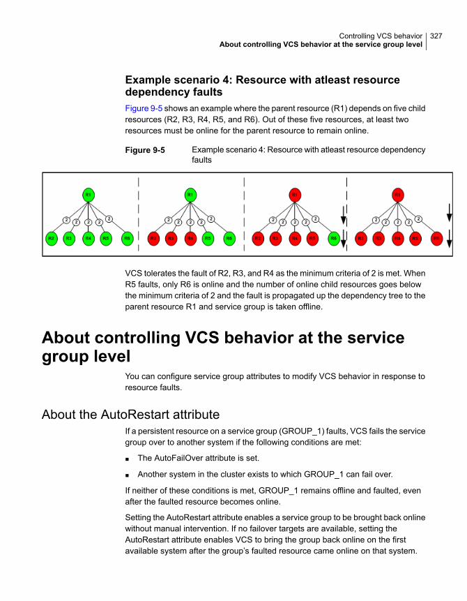
Example scenario 4: Resource with atleast resourcedependency faultsFigure 9-5 shows an example where the parent resource (R1) depends on five childresources (R2, R3, R4, R5, and R6). Out of these five resources, at least tworesources must be online for the parent resource to remain online.
Figure 9-5 Example scenario 4: Resource with atleast resource dependencyfaults
VCS tolerates the fault of R2, R3, and R4 as the minimum criteria of 2 is met. WhenR5 faults, only R6 is online and the number of online child resources goes belowthe minimum criteria of 2 and the fault is propagated up the dependency tree to theparent resource R1 and service group is taken offline.
About controlling VCS behavior at the servicegroup level
You can configure service group attributes to modify VCS behavior in response toresource faults.
About the AutoRestart attributeIf a persistent resource on a service group (GROUP_1) faults, VCS fails the servicegroup over to another system if the following conditions are met:
■ The AutoFailOver attribute is set.
■ Another system in the cluster exists to which GROUP_1 can fail over.
If neither of these conditions is met, GROUP_1 remains offline and faulted, evenafter the faulted resource becomes online.
Setting the AutoRestart attribute enables a service group to be brought back onlinewithout manual intervention. If no failover targets are available, setting theAutoRestart attribute enables VCS to bring the group back online on the firstavailable system after the group’s faulted resource came online on that system.
327Controlling VCS behaviorAbout controlling VCS behavior at the service group level

For example, NIC is a persistent resource. In some cases, when a system bootsand VCS starts, VCS probes all resources on the system. When VCS probes theNIC resource, the resource may not be online because the networking is not upand fully operational. In such situations, VCS marks the NIC resource as faulted,and does not bring the service group online. However, when the NIC resourcebecomes online and if AutoRestart is enabled, the service group is brought online.
About controlling failover on service group or system faultsThe AutoFailOver attribute configures service group behavior in response to servicegroup and system faults.
The possible values include 0, 1, and 2. You can set the value of this attribute as2 if you have enabled the HA/DR license and if the service group is a non-hybridservice group.
Table 9-1 shows the possible values for the attribute AutoFailover.
Table 9-1 Possible values of the AutoFailover attribute and their description
DescriptionAutoFailoverattribute value
VCS does not fail over the service group when a system or servicegroup faults.
If a fault occurs in a service group, the group is taken offline, dependingon whether any of its resources are configured as critical. If a systemfaults, the service group is not failed over to another system.
0
VCS automatically fails over the service group when a system or aservice group faults, provided a suitable node exists for failover.
The service group attributes SystemZones and FailOverPolicy impactthe failover behavior of the service group. For global clusters, the failoverdecision is also based on the ClusterFailOverPolicy.
See “Service group attributes” on page 680.
1
VCS automatically fails over the service group only if another suitablenode exists in the same system zone or sites.
If a suitable node does not exist in the same system zone or sites, VCSbrings the service group offline, and generates an alert foradministrator’s intervention. You can manually bring the group onlineusing the hagrp -online command.
Note: If SystemZones attribute is not defined, the failover behavior issimilar to AutoFailOver=1.
2
328Controlling VCS behaviorAbout controlling VCS behavior at the service group level
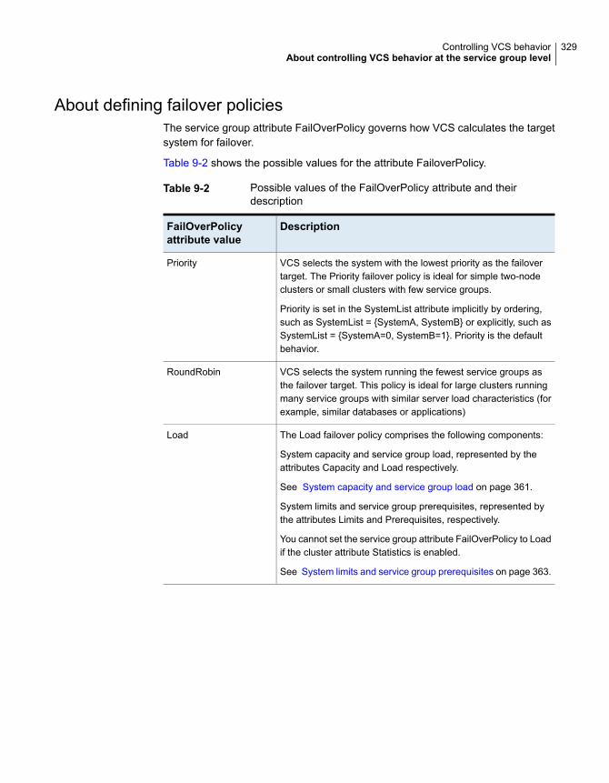
About defining failover policiesThe service group attribute FailOverPolicy governs how VCS calculates the targetsystem for failover.
Table 9-2 shows the possible values for the attribute FailoverPolicy.
Table 9-2 Possible values of the FailOverPolicy attribute and theirdescription
DescriptionFailOverPolicyattribute value
VCS selects the system with the lowest priority as the failovertarget. The Priority failover policy is ideal for simple two-nodeclusters or small clusters with few service groups.
Priority is set in the SystemList attribute implicitly by ordering,such as SystemList = {SystemA, SystemB} or explicitly, such asSystemList = {SystemA=0, SystemB=1}. Priority is the defaultbehavior.
Priority
VCS selects the system running the fewest service groups asthe failover target. This policy is ideal for large clusters runningmany service groups with similar server load characteristics (forexample, similar databases or applications)
RoundRobin
The Load failover policy comprises the following components:
System capacity and service group load, represented by theattributes Capacity and Load respectively.
See System capacity and service group load on page 361.
System limits and service group prerequisites, represented bythe attributes Limits and Prerequisites, respectively.
You cannot set the service group attribute FailOverPolicy to Loadif the cluster attribute Statistics is enabled.
See System limits and service group prerequisites on page 363.
Load
329Controlling VCS behaviorAbout controlling VCS behavior at the service group level

Table 9-2 Possible values of the FailOverPolicy attribute and theirdescription (continued)
DescriptionFailOverPolicyattribute value
VCS selects a system based on the forecasted available capacityfor all systems in the SystemList. The system with the highestforecasted available capacity is selected.
This policy can be set only if the cluster attribute Statistics is setto Enabled. The service group attribute Load is defined in termsof CPU, Memory, and Swap in absolute units. The unit can be ofthe following values:
■ CPU, MHz, or GHz for CPU■ GB or MB for Memory■ GB or MB for Swap
See “Cluster attributes” on page 722.
BiggestAvailable
About AdaptiveHAAdaptiveHA enables VCS to dynamically select the biggest available target systemto fail over an application when you set the service group attribute FailOverPolicyto BiggestAvailable. VCS monitors and forecasts the available capacity of systemsin terms of CPU, memory, and swap to select the biggest available system.
Enabling AdaptiveHA for a service groupAdaptiveHA enables VCS to make dynamic decisions about failing over anapplication to the biggest available system.
To enable AdaptiveHA for a service group
1 Ensure cluster attribute Statistics is set to Enabled. You can check by usingthe following command,
# haclus -display|grep Statistics
You cannot edit this value at run time.
2 Set the Load of the service group in terms of CPU, Memory, or Swap in absoluteunits. The unit can be of any following values:
■ CPU, MHz, or GHz for CPU
■ GB or MB for Memory
■ GB or MB for Swap
330Controlling VCS behaviorAbout controlling VCS behavior at the service group level

Define at least one key for the Load attribute.
3 Check the default value of the MeterWeight attribute at the cluster level. If theattribute does not meet the service group's meter weight requirement, then setthe MeterWeight at the service group level.
4 Set or edit the values for the following service group attributes in main.cf:
■ Modify the values of Load and MeterWeight as decided in the precedingsteps.
■ Set the value of FailOverPolicy to BiggestAvailable.You can set or edit the service group level attributes Load, MeterWeight,and FailOverPolicy during run time.
After you complete the above steps, AdaptiveHA is enabled. The service groupfollows the BiggestAvailable policy during a failover.
The following table provides information on various attributes and the values theycan take to enable AdaptiveHA:
Table 9-3
Attribute values to be setUse-case
Set the cluster attribute Statistics toMeterHostOnly.
To turn on host metering
Set the cluster attribute Statistics to Disabled.To turn off host metering
Set the cluster attribute Statistics to Enabled.To turn on host metering and forecasting
Set the cluster attribute Statistics to Enabledand also set the service group attribute Loadbased on your application’s CPU, Mem orSwap usage.
To enable hagrp -forecast CLI option
Verify the value of cluster attributeHostAvailableMeters.
To check the meters supported for any hostor cluster node
Perform the following actions:
■ Set the cluster attribute Statistics toEnabled
■ Set the service group attributeFailOverPolicy to BiggestAvailable.
■ Set service group attribute Load based onyour application’s CPU, Mem or Swapusage.
■ Optionally, set the service group attributeMeterWeight.
To enable host metering, forecast, and policydecisions using forecast
331Controlling VCS behaviorAbout controlling VCS behavior at the service group level

Table 9-3 (continued)
Attribute values to be setUse-case
Set the MeterInterval and ForecastCycle keysin the cluster attribute MeterControlaccordingly.
To change metering or forecast frequency
Use the following commands to check valuesfor available capacity and its forecast:
■ # hasys -value system_nameAvailableCapacity
■ # hasys -value system_nameHostAvailableForecast
To check the available capacity and itsforecast
The metering value is up-to-date when thedifference between GlobalCounter andAvailableGC is less than or equal to 24.
The forecasting value is up-to-date when thedifference between GlobalCounter andAvailableGC is less than or equal to 72.
To check if the metering and forecast isup-to-date
See “Cluster attributes” on page 722.
See “Service group attributes” on page 680.
See System attributes on page 707.
Considerations for setting FailOverPolicy toBiggestAvailableParent or child service group linked with local dependency, and FailOverPolicy setto BiggestAvailable should have the same MeterWeight values. If the MeterWeightis not same for these groups, then the engine refers to the cluster attributeMeterWeight.
Note: The MeterWeight settings enable VCS to decide the target system for a childservice group based on the perferred system for the parent service group.
See “Enabling AdaptiveHA for a service group” on page 330.
332Controlling VCS behaviorAbout controlling VCS behavior at the service group level

Limitations on AdaptiveHAWhen the cluster attribute Statistics in not “disabled”, then VCS meters the realmemory that is assigned and available on the system. By default, memory meteringis enabled.
If AIX advanced features like AME (Active Memory Expansion) or AMS (ActiveMemory Sharing) are enabled, the metered values may differ from the actual valuesavailable for the application. The metering of memory on AIX is not supported dueto these advanced memory features. Ensure that the “Mem” key is removed fromthe cluster attribute HostMeters. Also, if the FailOverPolicy is set to BiggestAvailablethen the “Mem” key must be removed from the service group attributes Load andMeterWeight.
Manually upgrading the VCS configuration file to the latestversionThe VCS configuration file (main.cf) gets automatically upgraded when you upgradefrom older versions of VCS using the installer.
If you chose to upgrade VCS manually, ensure that you update the VCSconfiguration file to include the following changes:
■ The Capacity attribute of system and Load attribute of service group are changedfrom scalar integer to integer-association (multidimensional) type attributes.For example, if the System has Capacity attribute defined and service grouphas Load attribute set in the main.cf file as:
Group Gx (
....
Load = { Units = 20 }
)
System N1 (
....
Capacity = 30
)
To update the main.cf file, update the Capacity values for Load and Systemattributes as follows:
Group Gx (
....
Load = { Units = 20 }
)
System N1 (
....
333Controlling VCS behaviorAbout controlling VCS behavior at the service group level

Capacity = { Units = 30 }
)
■ If the cluster attribute HostMonLogLvl is defined in the main.cf file, then replaceit with Statistics and make the appropriate change from the following:
■ Replace HostMonLogLvl = ALL with Statistics = MeterHostOnly.
■ Replace HostMonLogLvl = AgentOnly with Statistics = MeterHostOnly.
Note: For HostMonLogLvl value of AgentOnly, no exact equivalent value forStatistics exists. However, when you set Statistics to MeterHostOnly, VCSlogs host utilization messages in the engine logs and in the HostMonitoragent logs.
■ Replace HostMonLogLvl = Disabled with Statistics = Disabled.
See “About the main.cf file” on page 60.
About system zonesThe SystemZones attribute enables you to create a subset of systems to use in aninitial failover decision. This feature allows fine-tuning of application failoverdecisions, and yet retains the flexibility to fail over anywhere in the cluster.
If the attribute is configured, a service group tries to stay within its zone beforechoosing a host in another zone. For example, in a three-tier applicationinfrastructure with Web, application, and database servers, you could create twosystem zones: one each for the application and the database. In the event of afailover, a service group in the application zone will try to fail over to another nodewithin the zone. If no nodes are available in the application zone, the group will failover to the database zone, based on the configured load and limits.
In this configuration, excess capacity and limits on the database backend are keptin reserve to handle the larger load of a database failover. The application servershandle the load of service groups in the application zone. During a cascading failure,the excess capacity in the cluster is available to all service groups.
About sitesThe SiteAware attribute enables you to create sites to use in an initial failoverdecision in campus clusters. A service group can failover to another site even thougha failover target is available within the same site. If the SiteAware attribute is set to1, you cannot configure SystemZones. You can define site dependencies to restrict
334Controlling VCS behaviorAbout controlling VCS behavior at the service group level

dependent applications to fail over within the same site. If the SiteAware attributeis configured and set to 2, then the service group will failover within the same site.
For example, in a campus cluster with two sites, siteA and siteB, you can define asite dependency among service groups in a three-tier application infrastructure.The infrastructure consists of Web, application, and database to restrict the servicegroup failover within same site.
See “ How VCS campus clusters work” on page 530.
Load-based autostartVCS provides a method to determine where a service group comes online whenthe cluster starts. Setting the AutoStartPolicy to Load instructs the VCS engine,HAD, to determine the best system on which to start the groups. VCS places servicegroups in an AutoStart queue for load-based startup as soon as the groups probeall running systems. VCS creates a subset of systems that meet all prerequisitesand then chooses the system with the highest AvailableCapacity.
Set AutoStartPolicy = Load and configure the SystemZones attribute to establisha list of preferred systems on which to initially run a group.
About freezing service groupsFreezing a service group prevents VCS from taking any action when the servicegroup or a system faults. Freezing a service group prevents dependent resourcesfrom going offline when a resource faults. It also prevents the Clean function frombeing called on a resource fault.
You can freeze a service group when performing operations on its resources fromoutside VCS control. This prevents VCS from taking actions on resources whileyour operations are on. For example, freeze a database group when using databasecontrols to stop and start a database.
About controlling Clean behavior on resource faultsThe ManageFaults attribute specifies whether VCS calls the Clean function whena resource faults. ManageFaults can be configured at both resource level andservice group level. The values of this attribute at the resource level supersedethose at the service group level.
You can configure the ManageFaults attribute with the following possible values:
■ If the ManageFaults attribute is set to ALL, VCS calls the Clean function whena resource faults.
335Controlling VCS behaviorAbout controlling VCS behavior at the service group level

■ If the ManageFaults attribute is set to NONE, VCS takes no action on a resourcefault; it "hangs the service group until administrative action can be taken. VCSmarks the resource state as ADMIN_WAIT and does not fail over the servicegroup until the resource fault is removed and the ADMIN_WAIT state is cleared.VCS calls the resadminwait trigger when a resource enters the ADMIN_WAITstate due to a resource fault if the ManageFaults attribute is set to NONE. Youcan customize this trigger to provide notification about the fault.When ManageFaults is set to NONE and one of the following events occur, theresource enters the ADMIN_WAIT state:
Table 9-4 lists the possible events and the subsequent state of the resource whenthe ManageFaults attribute is set to NONE.
Table 9-4 Possible events when the ManageFaults attribute is set to NONE
Resource stateEvent
ONLINE|ADMIN_WAITThe offline function did not complete withinthe expected time.
ONLINE|ADMIN_WAITThe offline function was ineffective.
OFFLINE|ADMIN_WAITThe online function did not complete withinthe expected time.
OFFLINE|ADMIN_WAITThe online function was ineffective.
ONLINE|ADMIN_WAITThe resource was taken offline unexpectedly.
ONLINE|MONITOR_TIMEDOUT|ADMIN_WAITFor the online resource the monitor functionconsistently failed to complete within theexpected time.
Clearing resources in the ADMIN_WAIT stateWhen VCS sets a resource in the ADMIN_WAIT state, it invokes the resadminwaittrigger according to the reason the resource entered the state.
See “About the resadminwait event trigger” on page 428.
336Controlling VCS behaviorAbout controlling VCS behavior at the service group level

To clear a resource
1 Take the necessary actions outside VCS to bring all resources into the requiredstate.
2 Verify that resources are in the required state by issuing the command:
hagrp -clearadminwait group -sys system
This command clears the ADMIN_WAIT state for all resources. If VCS continuesto detect resources that are not in the required state, it resets the resourcesto the ADMIN_WAIT state.
3 If resources continue in the ADMIN_WAIT state, repeat step 1 and step 2, orissue the following command to stop VCS from setting the resource to theADMIN_WAIT state:
hagrp -clearadminwait -fault group -sys system
This command has the following results:
■ If the resadminwait trigger was called for the reasons 0 or 1, the resourcestate is set as ONLINE|UNABLE_TO_OFFLINE.
■ 0 = The offline function did not complete within the expected time.
■ 1 = The offline function was ineffective.
■ If the resadminwait trigger was called for reasons 2, 3, or 4, the resourcestate is set as FAULTED. Note that when resources are set as FAULTEDfor these reasons, the clean function is not called. Verify that resources inADMIN-WAIT are in clean, OFFLINE state prior to invoking this command.
■ 2 = The online function did not complete within the expected time.
■ 3 = The online function was ineffective.
■ 4 = The resource was taken offline unexpectedly.
When a service group has a resource in the ADMIN_WAIT state, the followingservice group operations cannot be performed on the resource: online, offline,switch, and flush. Also, you cannot use the hastop command when resourcesare in the ADMIN_WAIT state. When this occurs, you must issue the hastopcommand with -force option only.
337Controlling VCS behaviorAbout controlling VCS behavior at the service group level
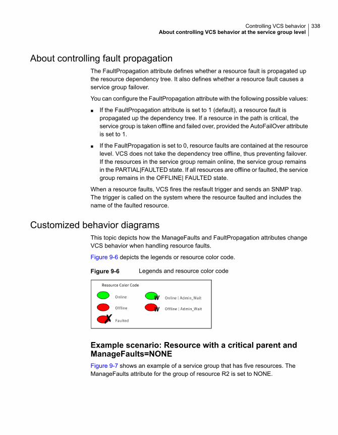
About controlling fault propagationThe FaultPropagation attribute defines whether a resource fault is propagated upthe resource dependency tree. It also defines whether a resource fault causes aservice group failover.
You can configure the FaultPropagation attribute with the following possible values:
■ If the FaultPropagation attribute is set to 1 (default), a resource fault ispropagated up the dependency tree. If a resource in the path is critical, theservice group is taken offline and failed over, provided the AutoFailOver attributeis set to 1.
■ If the FaultPropagation is set to 0, resource faults are contained at the resourcelevel. VCS does not take the dependency tree offline, thus preventing failover.If the resources in the service group remain online, the service group remainsin the PARTIAL|FAULTED state. If all resources are offline or faulted, the servicegroup remains in the OFFLINE| FAULTED state.
When a resource faults, VCS fires the resfault trigger and sends an SNMP trap.The trigger is called on the system where the resource faulted and includes thename of the faulted resource.
Customized behavior diagramsThis topic depicts how the ManageFaults and FaultPropagation attributes changeVCS behavior when handling resource faults.
Figure 9-6 depicts the legends or resource color code.
Figure 9-6 Legends and resource color code
Example scenario: Resource with a critical parent andManageFaults=NONEFigure 9-7 shows an example of a service group that has five resources. TheManageFaults attribute for the group of resource R2 is set to NONE.
338Controlling VCS behaviorAbout controlling VCS behavior at the service group level

Figure 9-7 Scenario: Resource with a critical parent andManageFaults=NONE
If resource R2 fails, the resource is marked as ONLINE|ADMIN_WAIT. The Cleanfunction is not called for the resource. VCS does not take any other resource offline.
Example scenario: Resource with a critical parent andFaultPropagation=0Figure 9-8 ahows an example where the FaultPropagation attribute is set to 0.
Figure 9-8 Scenario: Resource with a critical parent and FaultPropagation=0
When resource R2 faults, the Clean function is called and the resource is markedas faulted. The fault is not propagated up the tree, and the group is not taken offline.
About preventing concurrency violationIf a failover service group comes online on more than one node, the chances ofdata corruption increase. You can configure failover service groups that containapplication resources for prevention of concurrency violation (PCV) by setting thegroup's ProPCV attribute to 1.
Note: You cannot set the ProPCV attribute for parallel service groups and for hybridservice groups.
You can set the ProPCV attribute when the service group is inactive on all the nodesor when the group is active (ONLINE, PARTIAL, or STARTING) on one node in the
339Controlling VCS behaviorAbout controlling VCS behavior at the service group level

cluster. You cannot set the ProPCV attribute if the service group is already onlineon multiple nodes in the cluster. See “Service group attributes” on page 680.
If ProPCV is set to 1, you cannot bring online processes that are listed in theMonitorProcesses attribute or the StartProgram attribute of the application resourceon any other node in the cluster. If you try to start a process that is listed in theMonitorProcesses attribute or StartProgram attribute on any other node, that processis killed before it starts. Therefore, the service group does not get into concurrencyviolation.
Enabling or preventing resources to start outside VCScontrolWhen a resource is brought online on one node in a cluster, the resource must notbe allowed to come online outside VCS control on any other node in the cluster.By ensuring that the resource cannot be online on more than one node, you canprevent data corruption and ensure high availability through VCS.
The ProPCV attribute of the service group containing application resourcedetermines whether or not to allow the processes for the application resource tostart outside VCS control. The application type resource must be registered withIMF for offline monitoring or online monitoring. ProPCV applies only to the processesthat are specified in the MonitorProcesses attribute or the StartProgram attributeof the application type resource. See theCluster Server Bundled Agents ReferenceGuide for information about the propcv action agent function and also for informationon when the application resource can be registered with IMF for offline monitoring.
Note: Currently, ProPCV works for application type resources only.
In situations where the propcv action agent function times out, you can use theamfregister command to manually mark a resource as one of the following:
■ A resource that is allowed to be brought online outside VCS control.
■ A resource that is prevented from being brought online outside VCS control.Such a ProPCV-enabled resource cannot be online on more than one node inthe cluster.
340Controlling VCS behaviorAbout controlling VCS behavior at the service group level

To allow a resource to be started outside VCS control
◆ Type the following command:
amfregister -r reapername -g resourcename -P a
Example: amfregister -r VCSApplicationAgent -g app1 -P a
The application resource app1 is allowed to start if you invoke it outside VCScontrol or from the command line.
To prevent a resource from being started outside VCS control
◆ Type the following command:
amfregister -r reapername ‐g resourcename ‐P p
Example: amfregister -r VCSApplicationAgent -g app1 -P p
The application resource app1 is prevented from starting if you invoke it outsideVCS control or from the command line.
In the preceding examples,
■ reapername is the agent whose name is displayed under the Registered Reaperssection of amfstat output. For application resources, reapername isVCSApplicationAgent.
■ Option r indicates the name of the reaper or agent as displayed under theRegistered Reapers section of the amfstat command’s output. For applicationresources, reaper name is VCSApplicationAgent.
■ resourcename is the resource name.
■ Option g indicates the name of the resource. In the preceding example, theapplication resource is app1.
■ Option P indicates whether to allow or prevent a resource from starting up outsideVCS control.
■ Argument a denotes that the resource can be started outside VCS control.
■ Argument p denotes that the resource is prevented from starting outsideVCS control.
Limitations of ProPCVThe following limitations apply:
■ ProPCV feature is supported only when the Mode value for the IMF attribute ofthe Application type resource is set to 3 on all nodes in the cluster.
■ The ProPCV feature does not protect against concurrency in the following cases:
341Controlling VCS behaviorAbout controlling VCS behavior at the service group level
When you modify the IMFRegList attribute for the resource type.■
■ When you modify any value that is part of the IMFRegList attribute for theresource type.
■ If you configure the application type resource for ProPCV, consider the following:
■ If you run the process with changed order of arguments, the ProPCV featuredoes not prevent the execution of the process.For example, a single command can be run in multiple ways:
/usr/bin/tar -c -f a.tar
/usr/bin/tar -f a.tar -c
The ProPCV feature works only if you run the process the same way as itis configured in the resource configuration.
■ If there are multiple ways or commands to start a process, ProPCV preventsthe startup of the process only if the process is started in the way specifiedin the resource configuration.
■ If the process is started using a script, the script must have the interpreterpath as the first line and start with #!. For example, a shell script should startwith “#!/usr/bin/sh”
■ You can bring processes online outside VCS control on another node when afailover service group is auto-disabled.
Examples are:
■ When you use the hastop -local command or the hastop -local -force
command on a node.
■ When a node is detected as FAULTED after its ShutdownTimeout value haselapsed because HAD exited.
In such situations, you can bring processes online outside VCS control on anode even if the failover service group is online on another node on which VCSengine is not running.
■ Before you set ProPCV to 1 for a service group, you must ensure that none ofthe processes specified in the MonitorProcesses attribute or the StartProgramattribute of the application resource of the group are running on any node wherethe resource is offline. If an application resource lists two processes in itsMonitorProcesses attribute, both processes need to be offline on all nodes inthe cluster. If a node has only one process running and you set ProPCV to 1for the group, you can still start the second process on another node becausethe Application agent cannot perform selective offline monitoring or onlinemonitoring of individual processes for an application resource
342Controlling VCS behaviorAbout controlling VCS behavior at the service group level

■ If a ProPCV-enabled service group has some application resources and somenon-application type resources (that cannot be configured for ProPCV), thegroup can still get into concurrency violation for the non-application typeresources. You can bring the non-application type resources online outside VCScontrol on a node when the service group is active on another node. In suchcases, the concurrency violation trigger is invoked.
■ The ProPCV feature is not supported for an application running in a container(such as WPAR).
■ When ProPCV is enabled for a group, the AMF driver prevents certain processesfrom starting based on the process offline registrations with the AMF driver. Ifa process starts whose pathname and arguments match with the registeredevent, and if the prevent action is set for this registered event, that process isprevented from starting. Apart from that, if the arguments match, and even ifonly the basename of the starting process matches with the basename of thepathname of the registered event, AMF driver prevents that process from starting
■ Even with ProPCV enabled, the AMF driver can prevent only those processesfrom starting whose pathname and arguments match with the events registeredwith the AMF driver. If the same process is started in some other manner (forexample, with a totally different pathname), AMF driver does not prevent theprocess from starting. This behavior is in line with how AMF driver works forprocess offline monitoring.
VCS behavior for resources that support the intentional offlinefunctionality
Certain agents can identify when an application has been intentionally shut downoutside of VCS control.
For agents that support this functionality, if an administrator intentionally shuts downan application outside of VCS control, VCS does not treat it as a fault. VCS setsthe service group state as offline or partial, depending on the state of other resourcesin the service group.
This feature allows administrators to stop applications without causing a failover.The feature is available for V51 agents.
About the IntentionalOffline attributeTo configure a resource to recognize an intentional offline of configured application,set the IntentionalOffline attribute to 1. Set the attribute to its default value of 0 todisable this functionality. IntentionalOffline is Type level attribute and not a resourcelevel attribute.
You can configure the IntentionalOffline attribute with the following possible values:
343Controlling VCS behaviorAbout controlling VCS behavior at the service group level

■ If you set the attribute to 1: When the application is intentionally stopped outsideof VCS control, the resource enters an OFFLINE state. This attribute does notaffect VCS behavior on application failure. VCS continues to fault resources ifmanaged corresponding applications fail.
■ If you set the attribute to 0: When the application is intentionally stopped outsideof VCS control, the resource enters a FAULTED state.
About the ExternalStateChange attributeUse the ExternalStateChange attribute to control service group behavior when aconfigured application is intentionally started or stopped outside of VCS control.
The attribute defines how VCS handles service group state when resources areintentionally brought online or taken offline outside of VCS control.
You can configure the ExternalStateChange attribute with the values listed inTable 9-5.
Table 9-5 ExternalStateChange attribute values
Service group behaviorAttributevalue
If the configured application is started outside of VCS control, VCS bringsthe corresponding service group online. If you attempt to start theapplication on a frozen node or service group, VCS brings thecorresponding service group online once the node or the service group isunfrozen.
OnlineGroup
If the configured application is stopped outside of VCS control, VCS takesthe corresponding service group offline.
OfflineGroup
If a configured application is stopped outside of VCS control, VCS setsthe state of the corresponding VCS resource as offline. VCS does not takeany parent resources or the service group offline.
OfflineHold
OfflineHold and OfflineGroup are mutually exclusive.
VCS behavior when a service group is restartedThe VCS engine behavior is determined by certain service group-level attributeswhen service groups are restarted.
VCS behavior when non-persistent resources restartThe OnlineRetryLimit and OnlineRetryInterval attributes determine the VCS behaviorwhen the VCS engine attempts to bring a faulted non-persistent resource online.
344Controlling VCS behaviorAbout controlling VCS behavior at the service group level

The OnlineRetryLimit attribute allows a service group to be brought online againon the same system if a non-persistent resource in the service group faults. If, forsome reason, the service group cannot be restarted, the VCS engine repeatedlytries to bring the service group online till the number of attempts that are specifiedby OnlineRetryLimit expires.
However, if the OnlineRetryInterval attribute is set to a non-zero value, the servicegroup that has been successfully restarted faults again; it should be failed over.The service group should not be retried on the same system, even if the attributeOnlineRetryLimit is non-zero. This prevents a group from continuously faulting andrestarting on the same system. The interval is measured in seconds.
VCS behavior when persistent resources transition fromfaulted to onlineThe AutoRestart attribute determines the VCS behavior in the following scenarios:
■ A service group cannot be automatically started because of a faulted persistentresource
■ A service group is unable to failover
Later, when a persistent resource transitions from FAULTED to ONLINE, the VCSengine attempts to bring the service group online if the AutoRestart attribute is setto 1 or 2.
If AutoRestart is set to 1, the VCS engine restarts the service group. If AutoRestartis set to 2, the VCS engine clears the faults on all faulted non-persistent resourcesin the service group before it restarts the service group on the same system
About controlling VCS behavior at the resourcelevel
You can control VCS behavior at the resource level. Note that a resource is notconsidered faulted until the agent framework declares the fault to the VCS engine.
Certain attributes affect how the VCS agent framework reacts to problems withindividual resources before informing the fault to the VCS engine.
Resource type attributes that control resource behaviorThe following attributes affect how the VCS agent framework reacts to problemswith individual resources before informing the fault to the VCS engine.
345Controlling VCS behaviorAbout controlling VCS behavior at the resource level

About the RestartLimit attributeThe RestartLimit attribute defines whether VCS attempts to restart a failed resourcebefore it informs the engine of the fault.
If the RestartLimit attribute is set to a non-zero value, the agent attempts to restartthe resource before it declares the resource as Faulted. When the agent frameworkrestarts a failed resource, it first calls the Clean function and then the Online function.However, if the ManageFaults attribute is set to NONE, the agent does not call theClean function and does not retry the Online function. If you configure theManageFaults attribute at the resource level, it supersedes the values that areconfigured at the service group level.
About the OnlineRetryLimit attributeThe OnlineRetryLimit attribute specifies the number of times the Online function isretried if the initial attempt to bring a resource online is unsuccessful.
When OnlineRetryLimit is set to a non-zero value, the agent first calls the Cleanfunction and then reruns the Online function. However, if the ManageFaults attributeis set to NONE, the agent does not call the Clean function and does not retry theOnline function. If you configure the ManageFaults attribute at the resource level,it supersedes the values that are configured at the service group level.
About the ConfInterval attributeThe ConfInterval attribute defines how long a resource must remain online withoutencountering problems before previous problem counters are cleared. The attributecontrols when VCS clears the RestartCount, ToleranceCount andCurrentMonitorTimeoutCount values.
About the ToleranceLimit attributeThe ToleranceLimit attribute defines the number of times the monitor routine shouldreturn an offline status before declaring a resource offline. This attribute is typicallyused when a resource is busy and appears to be offline. Setting the attribute to anon-zero value instructs VCS to allow multiple failing monitor cycles with theexpectation that the resource will eventually respond. Setting a non-zeroToleranceLimit also extends the time required to respond to an actual fault.
About the FaultOnMonitorTimeouts attributeThe FaultOnMonitorTimeouts attribute defines whether VCS interprets a Monitorfunction timeout as a resource fault.
346Controlling VCS behaviorAbout controlling VCS behavior at the resource level
If the attribute is set to 0, VCS does not treat Monitor timeouts as a resource faults.If the attribute is set to 1, VCS interprets the timeout as a resource fault and theagent calls the Clean function to shut the resource down.
By default, the FaultOnMonitorTimeouts attribute is set to 4. This means that theMonitor function must time out four times in a row before the resource is markedfaulted. The first monitor time out timer and the counter of time outs are reset afterone hour of the first monitor time out.
How VCS handles resource faultsThis section describes the process VCS uses to determine the course of actionwhen a resource faults.
VCS behavior when an online resource faultsIn the following example, a resource in an online state is reported as being offlinewithout being commanded by the agent to go offline.
VCS goes through the following steps when an online resource faults:
■ VCS first verifies the Monitor routine completes successfully in the requiredtime. If it does, VCS examines the exit code returned by the Monitor routine. Ifthe Monitor routine does not complete in the required time, VCS looks at theFaultOnMonitorTimeouts (FOMT) attribute.
■ If FOMT=0, the resource will not fault when the Monitor routine times out. VCSconsiders the resource online and monitors the resource periodically, dependingon the monitor interval.If FOMT=1 or more, VCS compares the CurrentMonitorTimeoutCount (CMTC)with the FOMT value. If the monitor timeout count is not used up, CMTC isincremented and VCS monitors the resource in the next cycle.
■ If FOMT= CMTC, this means that the available monitor timeout count isexhausted and VCS must now take corrective action. VCS checks the Frozenattribute for the service group. If the service group is frozen, VCS declares theresource faulted and calls the resfault trigger. No further action is taken.
■ If the service group is not frozen, VCS checks the ManageFaults attribute at theresource level. VCS marks the resource as ONLINE|ADMIN_WAIT and firesthe resadminwait trigger if its group-level value is NONE or if its resource-levelvalue is IGNORE. If ManageFaults is set to ACT at the resource level or ALLat the group level, VCS invokes the Clean function with the reason MonitorHung.
347Controlling VCS behaviorAbout controlling VCS behavior at the resource level

Note: The resource-level ManageFaults value supersedes the correspondingservice group-level value. VCS honors the service group-level ManageFaultsvalue only when the corresponding resource-level value is blank ("").
■ If the Clean function is successful (that is, Clean exit code = 0), VCS examinesthe value of the RestartLimit attribute. If Clean fails (exit code = 1), the resourceremains online with the state UNABLE TO OFFLINE. VCS fires the resnotofftrigger and monitors the resource again.
■ If the Monitor routine does not time out, it returns the status of the resource asbeing online or offline.
■ If the ToleranceLimit (TL) attribute is set to a non-zero value, the Monitor cyclereturns offline (exit code = 100) for a number of times specified by theToleranceLimit and increments the ToleranceCount (TC). When theToleranceCount equals the ToleranceLimit (TC = TL), the agent declares theresource as faulted.
■ If the Monitor routine returns online (exit code = 110) during a monitor cycle,the agent takes no further action. The ToleranceCount attribute is reset to 0when the resource is online for a period of time specified by the ConfIntervalattribute.If the resource is detected as being offline a number of times specified by theToleranceLimit before the ToleranceCount is reset (TC = TL), the resource isconsidered faulted.
■ After the agent determines the resource is not online, VCS checks the Frozenattribute for the service group. If the service group is frozen, VCS declares theresource faulted and calls the resfault trigger. No further action is taken.
■ If the service group is not frozen, VCS checks the ManageFaults attribute. IfManageFaults=NONE, VCS marks the resource state as ONLINE|ADMIN_WAITand calls the resadminwait trigger. If ManageFaults=ALL, VCS calls the Cleanfunction with the CleanReason set to Unexpected Offline.
■ If the Clean function fails (exit code = 1) the resource remains online with thestate UNABLE TO OFFLINE. VCS fires the resnotoff trigger and monitors theresource again. The resource enters a cycle of alternating Monitor and Cleanfunctions until the Clean function succeeds or a user intervenes.
■ If the Clean function is successful, VCS examines the value of the RestartLimit(RL) attribute. If the attribute is set to a non-zero value, VCS increments theRestartCount (RC) attribute and invokes the Online function. This continues tillthe value of the RestartLimit equals that of the RestartCount. At this point, VCSattempts to monitor the resource.
348Controlling VCS behaviorAbout controlling VCS behavior at the resource level

■ If the Monitor returns an online status, VCS considers the resource online andresumes periodic monitoring. If the monitor returns an offline status, the resourceis faulted and VCS takes actions based on the service group configuration.
VCS behavior when a resource fails to come onlineIn the following example, the agent framework invokes the Online function for anoffline resource. The resource state changes to WAITING TO ONLINE.
VCS goes through the following steps when a resource fails to come online:
■ If the Online function times out, VCS examines the value of the ManageFaultsattribute first at the resource level and then at the service group level. IfManageFaults is defined at the resource level, VCS overrides the corresponding
349Controlling VCS behaviorAbout controlling VCS behavior at the resource level

values that are specified at the service group level. VCS takes action based onthe ManageFaults values that are specified at the resource level.
■ If ManageFaults is set to IGNORE at the resource level, the resource statechanges to OFFLINE|ADMIN_WAIT. The resource-level value overrides theservice group-level value.
■ If ManageFaults is set to ACT at the resource level, VCS calls the Clean functionwith the CleanReason set to Online Hung.
■ If resource-level ManageFaults is set to "" or blank, VCS checks thecorresponding service group-level value, and proceeds as follows:
■ If ManageFaults is set to NONE, the resource state changes toOFFLINE|ADMIN_WAIT.
■ If ManageFaults is set to ALL, VCS calls the Clean function with theCleanReason set to Online Hung.
■ If ManageFaults is set to NONE, the resource state changes toOFFLINE|ADMIN_WAIT.If ManageFaults is set to ALL, VCS calls the Clean function with the CleanReasonset to Online Hung.
■ If the Online function does not time out, VCS invokes the Monitor function. TheMonitor routine returns an exit code of 110 if the resource is online. Otherwise,the Monitor routine returns an exit code of 100.
■ VCS examines the value of the OnlineWaitLimit (OWL) attribute. This attributedefines how many monitor cycles can return an offline status before the agentframework declares the resource faulted. Each successive Monitor cycleincrements the OnlineWaitCount (OWC) attribute. When OWL= OWC (or ifOWL= 0), VCS determines the resource has faulted.
■ VCS then examines the value of the ManageFaults attribute. If the ManageFaultsis set to NONE, the resource state changes to OFFLINE|ADMIN_WAIT.If the ManageFaults is set to ALL, VCS calls the Clean function with theCleanReason set to Online Ineffective.
■ If the Clean function is not successful (exit code = 1), the agent monitors theresource. It determines the resource is offline, and calls the Clean function withthe Clean Reason set to Online Ineffective. This cycle continues till the Cleanfunction is successful, after which VCS resets the OnlineWaitCount value.
■ If the OnlineRetryLimit (ORL) is set to a non-zero value, VCS increments theOnlineRetryCount (ORC) and invokes the Online function. This starts the cycleall over again. If ORL = ORC, or if ORL = 0, VCS assumes that the Onlineoperation has failed and declares the resource as faulted.
350Controlling VCS behaviorAbout controlling VCS behavior at the resource level

100
ResourceOffline
MonitorExit Code
ManageFaults
NO
ORL >ORC? B
ORC=ORC+1
110
NO
ManageFaults
ResourceOffline | Admin_Waitresadminwait Trigger
ALL
YES
Online. ResourceWaiting to Online
A
OnlineTimeout?
ResourceOnline
OWL>OWC?
Clean.“Online Ineffective
ALL
Clean.“Online Hung
OWC =OWC+1
YES
YES
NONE ResourceOffline | Admin_Waitresadminwait Trigger
NONE
Reset OWC
CleanSuccess?
NO
NO
YES
VCS behavior after a resource is declared faultedAfter a resource is declared faulted, VCS fires the resfault trigger and examinesthe value of the FaultPropagation attribute.
VCS goes through the following steps after a resource is declared faulted:
■ If FaultPropagation is set to 0, VCS does not take other resources offline, andchanges the group state to OFFLINE|FAULTED or PARTIAL|FAULTED. Theservice group does not fail over.
351Controlling VCS behaviorAbout controlling VCS behavior at the resource level

If FaultPropagation is set to 1, VCS takes all resources in the dependent pathof the faulted resource offline, up to the top of the tree.
■ VCS then examines if any resource in the dependent path is critical. If noresources are critical, the service group is left in its OFFLINE|FAULTED orPARTIAL|FAULTED state. If a resource in the path is critical, VCS takes the allresources in the service group offline in preparation of a failover.
■ If the AutoFailOver attribute is set to 0, the service group is not failed over; itremains in a faulted state. If AutoFailOver is set to 1, VCS examines if anysystems in the service group’s SystemList are possible candidates for failover.If no suitable systems exist, the group remains faulted and VCS calls thenofailover trigger. If eligible systems are available, VCS examines theFailOverPolicy to determine the most suitable system to which to fail over theservice group.
■ If FailOverPolicy is set to Load, a NoFailover situation may occur because ofrestrictions placed on service groups and systems by Service Group WorkloadManagement.
352Controlling VCS behaviorAbout controlling VCS behavior at the resource level

No other resources affected.No group failover.
YES
A
Resource faults.resfault Trigger
FaultPropagation
0
1
Offline allresources independent path
Criticalresources?
NO
Offline entire tree
AutoFailover
Systemavailable?
No other resources affected.No group failover.
Service group offline inFaulted state.
0
NO Service group offline inFaulted state. Nofailovertrigger.
Failover based onFailOverPolicy
VCS behavior when a resource is restartedThe behavior of VCS agents is determined by certain resource-level attributes whenresources are restarted.
353Controlling VCS behaviorAbout controlling VCS behavior at the resource level

VCS behavior when online agent function fails to bring aresource onlineYou can use the OnlineRetryLimit attribute to specify the number of retries that theagent should perform to bring the resource online.
VCS behavior when a resource goes offlineThe RestartLimit attribute can be used to specify the number of retries that an agentshould perform to bring a resource online before the VCS engine declares theresource as FAULTED.
The ToleranceLimit attribute defines the number of times the monitor agent functioncan return unexpected OFFLINE before it declares the resource as FAULTED. Alarge ToleranceLimit value delays detection of a genuinely faulted resource.
For example, assume that RestartLimit is set to 2 and ToleranceLimit is set to 3 fora resource and that the resource state is ONLINE. If the next monitor detects theresource state as OFFLINE, the agent waits for another monitor cycle instead oftriggering a restart. The agent waits a maximum of 3 (ToleranceLimit) monitor cyclesbefore it triggers a restart.
The RestartLimit and ToleranceLimit attributes determine the VCS behavior in thefollowing scenarios:
■ The RestartLimit attribute is considered when the resource state is ONLINE andnext monitor cycle detects it as OFFLINE and ToleranceLimit is reached.
■ The OnlineRetryLimit attribute is considered when the resource is to be broughtonline.
About disabling resourcesDisabling a resource means that the resource is no longer monitored by a VCSagent, and that the resource cannot be brought online or taken offline. The agentstarts monitoring the resource after the resource is enabled. The resource attributeEnabled determines whether a resource is enabled or disabled. A persistent resourcecan be disabled when all its parents are offline. A non-persistent resource can bedisabled when the resource is in an OFFLINE state.
When to disable a resourceTypically, resources are disabled when one or more resources in the service groupencounter problems and disabling the resource is required to keep the servicegroup online or to bring it online.
354Controlling VCS behaviorAbout controlling VCS behavior at the resource level

Note: Disabling a resource is not an option when the entire service group requiresdisabling. In that case, set the service group attribute Enabled to 0.
Use the following command to disable the resource when VCS is running:
# hares -modify resource_name Enabled 0
To have the resource disabled initially when VCS is started, set the resource’sEnabled attribute to 0 in main.cf.
Limitations of disabling resourcesWhen VCS is running, there are certain prerequisites to be met before the resourceis disabled successfully.
■ An online non-persistent resource cannot be disabled. It must be in a cleanOFFLINE state. (The state must be OFFLINE and IState must be NOTWAITING.)
■ If it is a persistent resource and the state is ONLINE on some of the systems,all dependent resources (parents) must be in clean OFFLINE state. (The statemust be OFFLINE and IState must be NOT WAITING)
Therefore, before disabling the resource you may be required to take it offline (if itis non-persistent) and take other resources offline in the service group.
Additional considerations for disabling resourcesFollowing are the additional considerations for disabling resources:
■ When a group containing disabled resources is brought online, the onlinetransaction is not propagated to the disabled resources. Children of the disabledresource are brought online by VCS only if they are required by another enabledresource.
■ You can bring children of disabled resources online if necessary.
■ When a group containing disabled resources is taken offline, the offlinetransaction is propagated to the disabled resources.
■ If a service group is part of an hagrp -online -propagate operation or anhagrp -offline -propagate operation and a resource in the service group isdisabled, the resource might not complete its online operation or offline operation.In this case, PolicyIntention of the service group is set to 0.In an hagrp online -propagate operation, if the child service groups cannotbe brought online, the parent service groups also cannot be brought online.Therefore, when the PolicyIntention value of 1 for the child service group iscleared, the PolicyIntention value of all its parent service groups in dependency
355Controlling VCS behaviorAbout controlling VCS behavior at the resource level

tree is also cleared. When the PolicyIntention value of 2 for the parent servicegroup is cleared, the PolicyIntention value of all its child service groups independency tree is also cleared.
This section shows how a service group containing disabled resources is broughtonline.
Figure 9-9 shows Resource_3 is disabled. When the service group is brought online,the only resources brought online by VCS are Resource_1 and Resource_2(Resource_2 is brought online first) because VCS recognizes Resource_3 isdisabled. In accordance with online logic, the transaction is not propagated to thedisabled resource.
Figure 9-9 Scenario: Transaction not propagated to the disabled resource(Resource_3)
Resource_1
Resource_3Resource_3 is disabled.
Resource_2
Resource_4
Resource_5
Resource_4 is offline.
Resource_5 is offline.
Goingonling
Figure 9-10, shows that Resource_2 is disabled. When the service group is broughtonline, resources 1, 3, 4 are also brought online (Resource_4 is brought onlinefirst). Note Resource_3, the child of the disabled resource, is brought online becauseResource_1 is enabled and is dependent on it.
Figure 9-10 Scenario: Child of the disabled resource (Resource_3) is broughtonline
Resource_1 Resource_2Resource_2 is disabled.
Resource_3
Resource_4Going
onling
356Controlling VCS behaviorAbout controlling VCS behavior at the resource level

How disabled resources affect group statesWhen a service group is brought online containing non-persistent, disabled resourceswhose AutoStart attributes are set to 1, the group state is PARTIAL, even thoughenabled resources with Autostart=1 are online. This is because the disabled resourceis considered for the group state.
To have the group in the ONLINE state when enabled resources with AutoStart setto 1 are in ONLINE state, set the AutoStart attribute to 0 for the disabled,non-persistent resources.
Changing agent file paths and binariesBy default, VCS runs agent binaries from the path$VCS_HOME/bin/AgentName/AgentNameAgent. For example,/opt/VRTSvcs/bin/FileOnOff/FileOnOffAgent.
You can instruct VCS to run a different set of agent binaries or scripts by specifyingvalues for the following attributes.
■ AgentFile:Specify a value for this attribute if the name of the agent binary is not the sameas that of the resource type.For example, if the resource type is MyApplication and the agent binary is calledMyApp, set the AgentFile attribute to MyApp. For a script-base agent, you couldconfigure AgentFile as /opt/VRTSvcs/bin/ScriptAgent.
■ AgentDirectory:Specify a value for this attribute if the agent is not installed at the default location.When you specify the agent directory, VCS looks for the agent file(AgentNameAgent) in the agent directory. If the agent file name does not conformto the AgentNameAgent convention, configure the AgentFile attribute.For example, if the MyApplication agent is installed at/opt/VRTSvcs/bin/CustomAgents/MyApplication, specify this path as the attributevalue. If the agent file is not named MyApplicationAgent, configure the AgentFileattribute.If you do not set these attributes and the agent is not available at its defaultlocation, VCS looks for the agent at the/opt/VRTSagents/ha/bin/AgentName/AgentNameAgent.
357Controlling VCS behaviorChanging agent file paths and binaries

To change the path of an agent
◆ Before configuring a resource for the agent, set the AgentFile andAgentDirectory attributes of the agent’s resource type.
hatype -modify resource_type AgentFile \
"binary_name"
hatype -modify resource_type AgentDirectory \
"complete_path_to_agent_binary"
VCS behavior on loss of storage connectivityWhen a node loses connectivity to shared storage, input-output operations (I/O) tovolumes return errors and the disk group gets disabled. In this situation, VCS mustfail the service groups over to another node. This failover is to ensure thatapplications have access to shared storage. The failover involves deporting diskgroups from one node and importing them to another node. However, pending I/Osmust complete before the disabled disk group can be deported.
Pending I/Os cannot complete without storage connectivity. When VCS is notconfigured with I/O fencing and the PanicSystemOnDGLoss attribute of DiskGroupis not configured to panic the system, VCS assumes data is being read from orwritten to disks and does not declare the DiskGroup resource as offline. Thisbehavior prevents potential data corruption that may be caused by the disk groupbeing imported on two hosts. However, this also means that service groups remainonline on a node that does not have storage connectivity and the service groupscannot be failed over unless an administrator intervenes. This affects applicationavailability.
Some Fibre Channel (FC) drivers have a configurable parameter called failover,which defines the number of seconds for which the driver retries I/O commandsbefore returning an error. If you set the failover parameter to 0, the FC driver retriesI/O infinitely and does not return an error even when storage connectivity is lost.This also causes the Monitor function for the DiskGroup to time out and preventsfailover of the service group unless an administrator intervenes.
Disk group configuration and VCS behaviorTable 9-6 describes how the disk group state and the failover attribute define VCSbehavior when a node loses connectivity to shared storage.
358Controlling VCS behaviorVCS behavior on loss of storage connectivity

Table 9-6 Disk group state and the failover attribute define VCS behavior
VCS behavior onloss of storageconnectivity
Failover attributeDiskGroup stateCase
Fails over servicegroups to anothernode.
N secondsEnabled1
DiskGroup resourceremains online.
No failover.
N secondsDisabled2
DiskGroup resourceremains in monitortimed out state.
No failover.
0Enabled3
DiskGroup resourceremains online.
No failover.
0Disabled4
How VCS attributes control behavior on loss of storage connectivityYou can configure VCS attributes to ensure that a node panics on losing connectivityto shared storage. The panic causes service groups to fail over to another node.
A system reboot or shutdown could leave the system in a hung state because theoperating system cannot dump the buffer cache to the disk. The panic operationensures that VCS does not wait for I/Os to complete before triggering the failovermechanism, thereby ensuring application availability. However, you might have toperform a file system check when you restart the node.
The following attributes of the Diskgroup agent define VCS behavior on loss ofstorage connectivity:—
Defines whether the agent panics the systemwhen storage connectivity is lost or Monitortimes out.
PanicSystemOnDGLoss
359Controlling VCS behaviorVCS behavior on loss of storage connectivity

Specifies the number of consecutive monitortimeouts after which VCS calls the Cleanfunction to mark the resource as FAULTED orrestarts the resource.
If you set the attribute to 0, VCS does not treata Monitor timeout as a resource fault. Bydefault, the attribute is set to 4. This means thatthe Monitor function must time out four timesin a row before VCS marks the resourcefaulted.
When the Monitor function for the DiskGroupagent times out, (case 3 in the preceding table),the FaultOnMonitorTimeouts attribute defineswhen VCS interprets the resource as faultedand invokes the Clean function. If theCleanReason is "monitor hung", the systempanics.
For details about these attributes, see theCluster Server Bundled Agents ReferenceGuide.
FaultOnMonitorTimeouts
VCS behavior when a disk group is disabledFigure 9-11 describes VCS behavior for a disabled diskgroup.
Figure 9-11 VCS behavior when a disk group is disabled
Panic system(dump, crash, and
halt processes)
DG stateis
disabled
I/Ofencing
Log DGerror
No failover
Triggerfailover.
No
1, 2
Yes
0
Value ofPanicSystemOnDG
Loss?
Monitor
Clean EntryPoint
0
1, 2
Value ofPanicSystemOnDG
Loss?
Log DGerror
Attemptsdeport of DG
360Controlling VCS behaviorVCS behavior on loss of storage connectivity
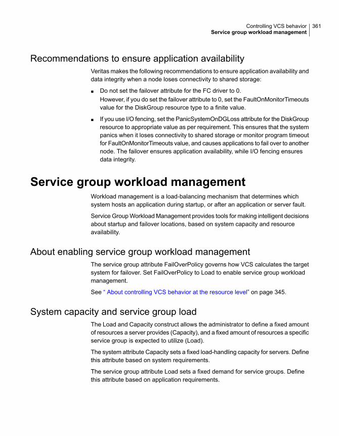
Recommendations to ensure application availabilityVeritas makes the following recommendations to ensure application availability anddata integrity when a node loses connectivity to shared storage:
■ Do not set the failover attribute for the FC driver to 0.However, if you do set the failover attribute to 0, set the FaultOnMonitorTimeoutsvalue for the DiskGroup resource type to a finite value.
■ If you use I/O fencing, set the PanicSystemOnDGLoss attribute for the DiskGroupresource to appropriate value as per requirement. This ensures that the systempanics when it loses connectivity to shared storage or monitor program timeoutfor FaultOnMonitorTimeouts value, and causes applications to fail over to anothernode. The failover ensures application availability, while I/O fencing ensuresdata integrity.
Service group workload managementWorkload management is a load-balancing mechanism that determines whichsystem hosts an application during startup, or after an application or server fault.
Service Group Workload Management provides tools for making intelligent decisionsabout startup and failover locations, based on system capacity and resourceavailability.
About enabling service group workload managementThe service group attribute FailOverPolicy governs how VCS calculates the targetsystem for failover. Set FailOverPolicy to Load to enable service group workloadmanagement.
See “ About controlling VCS behavior at the resource level” on page 345.
System capacity and service group loadThe Load and Capacity construct allows the administrator to define a fixed amountof resources a server provides (Capacity), and a fixed amount of resources a specificservice group is expected to utilize (Load).
The system attribute Capacity sets a fixed load-handling capacity for servers. Definethis attribute based on system requirements.
The service group attribute Load sets a fixed demand for service groups. Definethis attribute based on application requirements.
361Controlling VCS behaviorService group workload management

When a service group is brought online, its load is subtracted from the system’scapacity to determine available capacity. VCS maintains this info in the attributeAvailableCapacity.
When a failover occurs, VCS determines which system has the highest availablecapacity and starts the service group on that system. During a failover involvingmultiple service groups, VCS makes failover decisions serially to facilitate a properload-based choice.
System capacity is a soft restriction; in some situations, value of the Capacityattribute could be less than zero. During some operations, including cascadingfailures, the value of the AvailableCapacity attribute could be negative.
Static load versus dynamic loadDynamic load is an integral component of the Service Group Workload Managementframework. Typically, HAD sets remaining capacity with the function:
AvailableCapacity = Capacity - (sum of Load values of all online service groups)
If the DynamicLoad attribute is defined, its value overrides the calculated Loadvalues with the function:
AvailableCapacity = Capacity - DynamicLoad
This enables better control of system loading values than estimated service grouploading (static load). However, this requires setting up and maintaining a loadestimation package outside VCS. It also requires modifying the configuration filemain.cf manually.
Note that the DynamicLoad (specified with hasys -load) is subtracted from theCapacity as an integer and not a percentage value. For example, if a system’scapacity is 200 and the load estimation package determines the server is 80 percentloaded, it must inform VCS that the DynamicLoad value is 160 (not 80).
About overload warningOverload warning provides the notification component of the Load policy. When aserver sustains the preset load level (set by the attribute LoadWarningLevel) for apreset time (set by the attribute LoadTimeThreshold), VCS invokes the loadwarningtrigger.
See “Using event triggers” on page 422.
See System attributes on page 707.
The loadwarning trigger is a user-defined script or application designed to carry outspecific actions. It is invoked once, when system load exceeds theLoadWarningLevel for the LoadTimeThreshold. It is not invoked again until the
362Controlling VCS behaviorService group workload management
LoadTimeCounter, which determines how many seconds system load has beenabove LoadWarningLevel, is reset.
System limits and service group prerequisitesLimits is a system attribute and designates which resources are available on asystem, including shared memory segments and semaphores.
Prerequisites is a service group attribute and helps manage application requirements.For example, a database may require three shared memory segments and 10semaphores. VCS Load policy determines which systems meet the applicationcriteria and then selects the least-loaded system.
If the prerequisites defined for a service group are not met on a system, the servicegroup cannot be brought online on the system.
When configuring these attributes, define the service group’s prerequisites first,then the corresponding system limits. Each system can have a different limit andthere is no cap on the number of group prerequisites and system limits. Servicegroup prerequisites and system limits can appear in any order.
You can also use these attributes to configure the cluster as N-to-1 or N-to-N. Forexample, to ensure that only one service group can be online on a system at a time,add the following entries to the definition of each group and system:
Prerequisites = { GroupWeight = 1 }
Limits = { GroupWeight = 1 }
System limits and group prerequisites work independently of FailOverPolicy.Prerequisites determine the eligible systems on which a service group can bestarted. When a list of systems is created, HAD then follows the configuredFailOverPolicy.
About capacity and limitsWhen selecting a node as a failover target, VCS selects the system that meets theservice group’s prerequisites and has the highest available capacity. If multiplesystems meet the prerequisites and have the same available capacity, VCS selectsthe system appearing lexically first in the SystemList.
Systems having an available capacity of less than the percentage set by theLoadWarningLevel attribute, and those remaining at that load for longer than thetime specified by the LoadTimeThreshold attribute invoke the loadwarning trigger.
363Controlling VCS behaviorService group workload management

Sample configurations depicting workloadmanagement
This topic lists some sample configurations that use the concepts.
System and Service group definitionsThe main.cf in this example shows various Service Group Workload Managementattributes in a system definition and a service group definition.
See “About attributes and their definitions” on page 654.
include "types.cf"
cluster SGWM-demo (
)
system LargeServer1 (
Capacity = 200
Limits = { ShrMemSeg=20, Semaphores=10, Processors=12 }
LoadWarningLevel = 90
LoadTimeThreshold = 600
)
system LargeServer2 (
Capacity = 200
Limits = { ShrMemSeg=20, Semaphores=10, Processors=12 }
LoadWarningLevel=70
LoadTimeThreshold=300
)
system MedServer1 (
Capacity = 100
Limits = { ShrMemSeg=10, Semaphores=5, Processors=6 }
)
system MedServer2 (
Capacity = 100
Limits = { ShrMemSeg=10, Semaphores=5, Processors=6 }
)
group G1 (
SystemList = { LargeServer1 = 0, LargeServer2 = 1,
MedServer1 = 2 , MedServer2 = 3 }
SystemZones = { LargeServer1=0, LargeServer2=0,
364Controlling VCS behaviorSample configurations depicting workload management

MedServer1=1, MedServer2=1 }
AutoStartPolicy = Load
AutoStartList = { MedServer1, MedServer2 }
FailOverPolicy = Load
Load = { Units = 100 }
Prerequisites = { ShrMemSeg=10, Semaphores=5, Processors=6 }
)
Sample configuration: Basic four-node clusterFollowing is the sample configuration for a basic four-node cluster:
include "types.cf"
cluster SGWM-demo
system Server1 (
Capacity = 100
)
system Server2 (
Capacity = 100
)
system Server3 (
Capacity = 100
)
system Server4 (
Capacity = 100
)
group G1 (
SystemList = { Server1 = 0, Server2 = 1,
Server3 = 2, Server4 = 3 }
AutoStartPolicy = Load
AutoStartList = { Server1 = 0, Server2 = 1,
Server3 = 2, Server4 = 3 }
FailOverPolicy = Load
Load = { CPU = 1, Mem = 2000 }
)
group G2 (
SystemList = { Server1 = 0, Server2 = 1,
365Controlling VCS behaviorSample configurations depicting workload management

Server3 = 2, Server4 = 3 }
AutoStartPolicy = Load
AutoStartList = { Server1, Server2, Server3, Server4 }
FailOverPolicy = Load
Load = { Units = 40 }
)
group G3 (
SystemList = { Server1 = 0, Server2 = 1,
Server3 = 2, Server4 = 3 }
AutoStartPolicy = Load
AutoStartList = { Server1, Server2, Server3, Server4 }
FailOverPolicy = Load
Load = { Units = 30 }
)
group G4 (
SystemList = { Server1 = 0, Server2 = 1,
Server3 = 2, Server4 = 3 }
AutoStartPolicy = Load
AutoStartList = { Server1, Server2, Server3, Server4 }
FailOverPolicy = Load
Load = { Units = 10 }
)
group G5 (
SystemList = { Server1 = 0, Server2 = 1,
Server3 = 2, Server4 = 3 }
AutoStartPolicy = Load
AutoStartList = { Server1, Server2, Server3, Server4 }
FailOverPolicy = Load
Load = { Units = 50 }
)
group G6 (
SystemList = { Server1 = 0, Server2 = 1,
Server3 = 2, Server4 = 3 }
AutoStartPolicy = Load
AutoStartList = { Server1, Server2, Server3, Server4 }
FailOverPolicy = Load
Load = { Units = 30 }
)
366Controlling VCS behaviorSample configurations depicting workload management
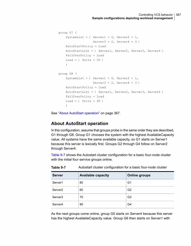
group G7 (
SystemList = { Server1 = 0, Server2 = 1,
Server3 = 2, Server4 = 3 }
AutoStartPolicy = Load
AutoStartList = { Server1, Server2, Server3, Server4 }
FailOverPolicy = Load
Load = { Units = 20 }
)
group G8 (
SystemList = { Server1 = 0, Server2 = 1,
Server3 = 2, Server4 = 3 }
AutoStartPolicy = Load
AutoStartList = { Server1, Server2, Server3, Server4 }
FailOverPolicy = Load
Load = { Units = 40 }
)
See “About AutoStart operation” on page 367.
About AutoStart operationIn this configuration, assume that groups probe in the same order they are described,G1 through G8. Group G1 chooses the system with the highest AvailableCapacityvalue. All systems have the same available capacity, so G1 starts on Server1because this server is lexically first. Groups G2 through G4 follow on Server2through Server4.
Table 9-7 shows the Autostart cluster configuration for a basic four-node clusterwith the initial four service groups online.
Table 9-7 Autostart cluster configuration for a basic four-node cluster
Online groupsAvailable capacityServer
G180Server1
G260Server2
G370Server3
G490Server4
As the next groups come online, group G5 starts on Server4 because this serverhas the highest AvailableCapacity value. Group G6 then starts on Server1 with
367Controlling VCS behaviorSample configurations depicting workload management

AvailableCapacity of 80. Group G7 comes online on Server3 with AvailableCapacityof 70 and G8 comes online on Server2 with AvailableCapacity of 60.
Table 9-8 shows the Autostart cluster configuration for a basic four-node clusterwith the other service groups online.
Table 9-8 Autostart cluster configuration for a basic four-node clusterwiththe other service groups online
Online groupsAvailable capacityServer
G1 and G650Server1
G2 and G820Server2
G3 and G750Server3
G4 and G540Server4
In this configuration, Server2 fires the loadwarning trigger after 600 seconds becauseit is at the default LoadWarningLevel of 80 percent.
About the failure scenarioIn the first failure scenario, Server4 fails. Group G4 chooses Server1 becauseServer1 and Server3 have AvailableCapacity of 50 and Server1 is lexically first.Group G5 then comes online on Server3. Serializing the failover choice allowscomplete load-based control and adds less than one second to the total failovertime.
Table 9-9 shows the cluster configuration following the first failure for a basicfour-node cluster.
Table 9-9 Cluster configuration following the first failure
Online groupsAvailable capacityServer
G1, G6, and G440Server1
G2 and G820Server2
G3, G7, and G50Server3
In this configuration, Server3 fires the loadwarning trigger to notify that the serveris overloaded. An administrator can then switch group G7 to Server1 to balancethe load across groups G1 and G3. When Server4 is repaired, it rejoins the clusterwith an AvailableCapacity value of 100, making it the most eligible target for afailover group.
368Controlling VCS behaviorSample configurations depicting workload management

About the cascading failure scenarioIf Server3 fails before Server4 can be repaired, group G3 chooses Server1, groupG5 chooses Server2, and group G7 chooses Server1. This results in the followingconfiguration:
Table 9-10 shows a cascading failure scenario for a basic four node cluster.
Table 9-10 Cascading failure scenario for a basic four node cluster
Online groupsAvailable capacityServer
G1, G6, G4, G3, and G7-10Server1
G2, G8, and G5-30Server2
Server1 fires the loadwarning trigger to notify that it is overloaded.
Sample configuration: Complex four-node clusterThe cluster in this example has two large enterprise servers (LargeServer1 andLargeServer2) and two medium-sized servers (MedServer1 and MedServer2). Ithas four service groups, G1 through G4, with various loads and prerequisites.Groups G1 and G2 are database applications with specific shared memory andsemaphore requirements. Groups G3 and G4 are middle-tier applications with nospecific memory or semaphore requirements.
include "types.cf"
cluster SGWM-demo (
)
system LargeServer1 (
Capacity = 200
Limits = { ShrMemSeg=20, Semaphores=10, Processors=12 }
LoadWarningLevel = 90
LoadTimeThreshold = 600
)
system LargeServer2 (
Capacity = 200
Limits = { ShrMemSeg=20, Semaphores=10, Processors=12 }
LoadWarningLevel=70
LoadTimeThreshold=300
)
system MedServer1 (
369Controlling VCS behaviorSample configurations depicting workload management

Capacity = 100
Limits = { ShrMemSeg=10, Semaphores=5, Processors=6 }
)
system MedServer2 (
Capacity = 100
Limits = { ShrMemSeg=10, Semaphores=5, Processors=6 }
)
group G1 (
SystemList = { LargeServer1 = 0, LargeServer2 = 1,
MedServer1 = 2, MedServer2 = 3 }
SystemZones = { LargeServer1=0, LargeServer2=0, MedServer1=1,
MedServer2=1 }
AutoStartPolicy = Load
AutoStartList = { LargeServer1, LargeServer2 }
FailOverPolicy = Load
Load = { Units = 100 }
Prerequisites = { ShrMemSeg=10, Semaphores=5, Processors=6 }
)
group G2 (
SystemList = { LargeServer1 = 0, LargeServer2 = 1,
MedServer1 = 2, MedServer2 = 3 }
SystemZones = { LargeServer1=0, LargeServer2=0, MedServer1=1,
MedServer2=1 }
AutoStartPolicy = Load
AutoStartList = { LargeServer1, LargeServer2 }
FailOverPolicy = Load
Load = { Units = 100 }
Prerequisites = { ShrMemSeg=10, Semaphores=5, Processors=6 }
)
group G3 (
SystemList = { LargeServer1 = 0, LargeServer2 = 1,
MedServer1 = 2, MedServer2 = 3 }
SystemZones = { LargeServer1=0, LargeServer2=0, MedServer1=1,
MedServer2=1 }
AutoStartPolicy = Load
AutoStartList = { MedServer1, MedServer2 }
FailOverPolicy = Load
Load = { Units = 30 }
)
370Controlling VCS behaviorSample configurations depicting workload management

group G4 (
SystemList = { LargeServer1 = 0, LargeServer2 = 1,
MedServer1 = 2, MedServer2 = 3 }
SystemZones = { LargeServer1=0, LargeServer2=0, MedServer1=1,
MedServer2=1 }
AutoStartPolicy = Load
AutoStartList = { MedServer1, MedServer2 }
FailOverPolicy = Load
Load = { Units = 20 }
)
About the AutoStart operationIn this configuration, the AutoStart sequence resembles:
G1—LargeServer1
G2—LargeServer2
G3—MedServer1
G4—MedServer2
All groups begin a probe sequence when the cluster starts. Groups G1 and G2have an AutoStartList of LargeServer1 and LargeServer2. When these groupsprobe, they are queued to go online on one of these servers, based on highestAvailableCapacity value. If G1 probes first, it chooses LargeServer1 becauseLargeServer1 and LargeServer2 both have an AvailableCapacity of 200, butLargeServer1 is lexically first. Groups G3 and G4 use the same algorithm todetermine their servers.
About the normal operationTable 9-11 shows the cluster configuration for a normal operation for a complexfour-node cluster.
Table 9-11 Normal operation cluster configuration for a complex four-nodecluster
Online groupsCurrent limitsAvailable capacityServer
G1ShrMemSeg=10
Semaphores=5
Processors=6
100LargeServer1
371Controlling VCS behaviorSample configurations depicting workload management
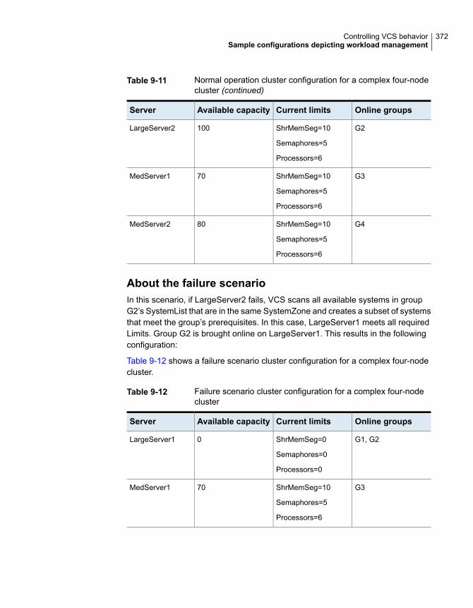
Table 9-11 Normal operation cluster configuration for a complex four-nodecluster (continued)
Online groupsCurrent limitsAvailable capacityServer
G2ShrMemSeg=10
Semaphores=5
Processors=6
100LargeServer2
G3ShrMemSeg=10
Semaphores=5
Processors=6
70MedServer1
G4ShrMemSeg=10
Semaphores=5
Processors=6
80MedServer2
About the failure scenarioIn this scenario, if LargeServer2 fails, VCS scans all available systems in groupG2’s SystemList that are in the same SystemZone and creates a subset of systemsthat meet the group’s prerequisites. In this case, LargeServer1 meets all requiredLimits. Group G2 is brought online on LargeServer1. This results in the followingconfiguration:
Table 9-12 shows a failure scenario cluster configuration for a complex four-nodecluster.
Table 9-12 Failure scenario cluster configuration for a complex four-nodecluster
Online groupsCurrent limitsAvailable capacityServer
G1, G2ShrMemSeg=0
Semaphores=0
Processors=0
0LargeServer1
G3ShrMemSeg=10
Semaphores=5
Processors=6
70MedServer1
372Controlling VCS behaviorSample configurations depicting workload management

Table 9-12 Failure scenario cluster configuration for a complex four-nodecluster (continued)
Online groupsCurrent limitsAvailable capacityServer
G4ShrMemSeg=10
Semaphores=5
Processors=6
80MedServer2
After 10 minutes (LoadTimeThreshold = 600) VCS fires the loadwarning trigger onLargeServer1 because the LoadWarningLevel exceeds 90 percent.
About the cascading failure scenarioIn this scenario, another system failure can be tolerated because each system hassufficient Limits to accommodate the service group running on its peer. IfMedServer1 fails, its groups can fail over to MedServer2.
If LargeServer1 fails, the failover of the two groups running on it is serialized. Thefirst group lexically, G1, chooses MedServer2 because the server meets the requiredLimits and has AvailableCapacity value. Group G2 chooses MedServer1 becauseit is the only remaining system that meets the required Limits.
Sample configuration: Server consolidationThe following configuration has a complex eight-node cluster running multipleapplications and large databases. The database servers, LargeServer1,LargeServer2, and LargeServer3, are enterprise systems. The middle-tier serversrunning multiple applications are MedServer1, MedServer2, MedServer3,MedServer4, and MedServer5.
In this configuration, the database zone (system zone 0) can handle a maximumof two failures. Each server has Limits to support a maximum of three databaseservice groups. The application zone has excess capacity built into each server.
The servers running the application groups specify Limits to support one database,even though the application groups do not run prerequisites. This allows a databaseto fail over across system zones and run on the least-loaded server in the applicationzone.
include "types.cf"
cluster SGWM-demo (
)
system LargeServer1 (
373Controlling VCS behaviorSample configurations depicting workload management

Capacity = 200
Limits = { ShrMemSeg=15, Semaphores=30, Processors=18 }
LoadWarningLevel = 80
LoadTimeThreshold = 900
)
system LargeServer2 (
Capacity = 200
Limits = { ShrMemSeg=15, Semaphores=30, Processors=18 }
LoadWarningLevel=80
LoadTimeThreshold=900
)
system LargeServer3 (
Capacity = 200
Limits = { ShrMemSeg=15, Semaphores=30, Processors=18 }
LoadWarningLevel=80
LoadTimeThreshold=900
)
system MedServer1 (
Capacity = 100
Limits = { ShrMemSeg=5, Semaphores=10, Processors=6 }
)
system MedServer2 (
Capacity = 100
Limits = { ShrMemSeg=5, Semaphores=10, Processors=6 }
)
system MedServer3 (
Capacity = 100
Limits = { ShrMemSeg=5, Semaphores=10, Processors=6 }
)
system MedServer4 (
Capacity = 100
Limits = { ShrMemSeg=5, Semaphores=10, Processors=6 }
)
system MedServer5 (
Capacity = 100
Limits = { ShrMemSeg=5, Semaphores=10, Processors=6 }
374Controlling VCS behaviorSample configurations depicting workload management

)
group Database1 (
SystemList = { LargeServer1 = 0, LargeServer2 = 1,
LargeServer3 = 2, MedServer1 = 3,
MedServer2 = 4, MedServer3 = 5,
MedServer4 = 6, MedServer5 = 6 }
SystemZones = { LargeServer1=0, LargeServer2=0,
LargeServer3=0,
MedServer1=1, MedServer2=1, MedServer3=1,
MedServer4=1,
MedServer5=1 }
AutoStartPolicy = Load
AutoStartList = { LargeServer1, LargeServer2, LargeServer3 }
FailOverPolicy = Load
Load = { Units = 100 }
Prerequisites = { ShrMemSeg=5, Semaphores=10, Processors=6 }
)
group Database2 (
SystemList = { LargeServer1 = 0, LargeServer2 = 1,
LargeServer3 = 2, MedServer1 = 3,
MedServer2 = 4, MedServer3 = 5,
MedServer4 = 6, MedServer5 = 6 }
SystemZones = { LargeServer1=0, LargeServer2=0,
LargeServer3=0,
MedServer1=1, MedServer2=1, MedServer3=1,
MedServer4=1,
MedServer5=1 }
AutoStartPolicy = Load
AutoStartList = { LargeServer1, LargeServer2, LargeServer3 }
FailOverPolicy = Load
Load = { Units = 100 }
Prerequisites = { ShrMemSeg=5, Semaphores=10, Processors=6 }
)
group Database3 (
SystemList = { LargeServer1 = 0, LargeServer2 = 1,
LargeServer3 = 2, MedServer1 = 3,
MedServer2 = 4, MedServer3 = 5,
MedServer4 = 6, MedServer5 = 6 }
SystemZones = { LargeServer1=0, LargeServer2=0,
LargeServer3=0,
375Controlling VCS behaviorSample configurations depicting workload management

MedServer1=1, MedServer2=1, MedServer3=1,
MedServer4=1,
MedServer5=1 }
AutoStartPolicy = Load
AutoStartList = { LargeServer1, LargeServer2, LargeServer3 }
FailOverPolicy = Load
Load = { Units = 100 }
Prerequisites = { ShrMemSeg=5, Semaphores=10, Processors=6 }
)
group Application1 (
SystemList = { LargeServer1 = 0, LargeServer2 = 1,
LargeServer3 = 2, MedServer1 = 3,
MedServer2 = 4, MedServer3 = 5,
MedServer4 = 6, MedServer5 = 6 }
SystemZones = { LargeServer1=0, LargeServer2=0,
LargeServer3=0,
MedServer1=1, MedServer2=1, MedServer3=1,
MedServer4=1,
MedServer5=1 }
AutoStartPolicy = Load
AutoStartList = { MedServer1, MedServer2, MedServer3,
MedServer4,
MedServer5 }
FailOverPolicy = Load
Load = { Units = 50 }
)
group Application2 (
SystemList = { LargeServer1 = 0, LargeServer2 = 1,
LargeServer3 = 2, MedServer1 = 3,
MedServer2 = 4, MedServer3 = 5,
MedServer4 = 6, MedServer5 = 6 }
SystemZones = { LargeServer1=0, LargeServer2=0,
LargeServer3=0,
MedServer1=1, MedServer2=1, MedServer3=1,
MedServer4=1,
MedServer5=1 }
AutoStartPolicy = Load
AutoStartList = { MedServer1, MedServer2, MedServer3,
MedServer4,
MedServer5 }
FailOverPolicy = Load
376Controlling VCS behaviorSample configurations depicting workload management

Load = { Units = 50 }
)
group Application3 (
SystemList = { LargeServer1 = 0, LargeServer2 = 1,
LargeServer3 = 2, MedServer1 = 3,
MedServer2 = 4, MedServer3 = 5,
MedServer4 = 6, MedServer5 = 6 }
SystemZones = { LargeServer1=0, LargeServer2=0,
LargeServer3=0,
MedServer1=1, MedServer2=1, MedServer3=1,
MedServer4=1,
MedServer5=1 }
AutoStartPolicy = Load
AutoStartList = { MedServer1, MedServer2, MedServer3,
MedServer4,
MedServer5 }
FailOverPolicy = Load
Load = { Units = 50 }
)
group Application4 (
SystemList = { LargeServer1 = 0, LargeServer2 = 1,
LargeServer3 = 2, MedServer1 = 3,
MedServer2 = 4, MedServer3 = 5,
MedServer4 = 6, MedServer5 = 6 }
SystemZones = { LargeServer1=0, LargeServer2=0,
LargeServer3=0,
MedServer1=1, MedServer2=1, MedServer3=1,
MedServer4=1,
MedServer5=1 }
AutoStartPolicy = Load
AutoStartList = { MedServer1, MedServer2, MedServer3,
MedServer4,
MedServer5 }
FailOverPolicy = Load
Load = { Units = 50 }
)
group Application5 (
SystemList = { LargeServer1 = 0, LargeServer2 = 1,
LargeServer3 = 2, MedServer1 = 3,
MedServer2 = 4, MedServer3 = 5,
377Controlling VCS behaviorSample configurations depicting workload management

MedServer4 = 6, MedServer5 = 6 }
SystemZones = { LargeServer1=0, LargeServer2=0,
LargeServer3=0,
MedServer1=1, MedServer2=1, MedServer3=1,
MedServer4=1,
MedServer5=1 }
AutoStartPolicy = Load
AutoStartList = { MedServer1, MedServer2, MedServer3,
MedServer4,
MedServer5 }
FailOverPolicy = Load
Load = { Units = 50 }
)
About the AutoStart operationBased on the preceding main.cf example, the AutoStart sequence resembles:
LargeServer1Database1
LargeServer2Database2
LargeServer3Database3
MedServer1Application1
MedServer2Application2
MedServer3Application3
MedServer4Application4
MedServer5Application5
About the normal operationTable 9-13 shows the normal operation cluster configuration for a complexeight-node cluster running multiple applications and large databases.
378Controlling VCS behaviorSample configurations depicting workload management

Table 9-13 Normal operation cluster configuration for a complex eight-nodecluster running multiple applications and large databases
Online groupsCurrent limitsAvailable capacityServer
Database1ShrMemSeg=10
Semaphores=20
Processors=12
100LargeServer1
Database2ShrMemSeg=10
Semaphores=20
Processors=12
100LargeServer2
Database3ShrMemSeg=10
Semaphores=20
Processors=12
100LargeServer3
Application1ShrMemSeg=5
Semaphores=10
Processors=6
50MedServer1
Application2ShrMemSeg=5
Semaphores=10
Processors=6
50MedServer2
Application3ShrMemSeg=5
Semaphores=10
Processors=6
50MedServer3
Application4ShrMemSeg=5
Semaphores=10
Processors=6
50MedServer4
Application5ShrMemSeg=5
Semaphores=10
Processors=6
50MedServer5
About the failure scenarioIn the following example, LargeServer3 fails. VCS scans all available systems inthe SystemList for the Database3 group for systems in the same SystemZone and
379Controlling VCS behaviorSample configurations depicting workload management

identifies systems that meet the group’s prerequisites. In this case, LargeServer1and LargeServer2 meet the required Limits. Database3 is brought online onLargeServer1. This results in the following configuration:
Table 9-14 shows the failure scenario for a complex eight-node cluster runningmultiple applications and large databases.
Table 9-14 Failure scenario for a complex eight-node cluster running multipleapplications and large databases
Online groupsCurrent limitsAvailable capacityServer
Database1 Database3ShrMemSeg=5
Semaphores=10
Processors=6
0LargeServer1
Database2ShrMemSeg=10
Semaphores=20
Processors=12
100LargeServer2
In this scenario, further failure of either system can be tolerated because each hassufficient Limits available to accommodate the additional service group.
About the cascading failure scenarioIf the performance of a database is unacceptable with two database groups runningon a single server, the SystemZones policy can help expedite performance. Failingover a database group into the application zone has the effect of resetting thegroup’s preferred zone. For example, in the above scenario Database3 was movedto LargeServer1. The administrator could reconfigure the application zone to movetwo application groups to a single system. The database application can then beswitched to the empty application server (MedServer1–MedServer5), which wouldput Database3 in Zone1 (application zone). If a failure occurs in Database3, thegroup selects the least-loaded server in the application zone for failover.
380Controlling VCS behaviorSample configurations depicting workload management

The role of service groupdependencies
This chapter includes the following topics:
■ About service group dependencies
■ Service group dependency configurations
■ Frequently asked questions about group dependencies
■ About linking service groups
■ About linking multiple child service groups
■ VCS behavior with service group dependencies
About service group dependenciesService groups can be dependent on each other. The dependent group is the parentand the other group is the child. For example a finance application (parent) mayrequire that the database application (child) is online before it comes online. Whileservice group dependencies offer more features to manage application servicegroups, they create more complex failover configurations.
A service group may function both as a parent and a child. In VCS, a dependencytree may be up to five levels deep.
About dependency linksThe dependency relationship between a parent and a child is called a link. The linkis characterized by the dependency category, the location of the service groups,and the rigidity of dependency.
10Chapter

■ A dependency may be online, or offline.
■ A dependency may be local, global, remote, or site.
■ A dependency may be soft, firm, or hard with respect to the rigidity of theconstraints between parent and child service group.
You can customize the behavior of service groups by choosing the right combinationof the dependency category, location, and rigidity
Dependency categoriesDependency categories determine the relationship of the parent group with thestate of the child group.
Table 10-1 shows dependency categories and relationships between parent andchild service groups.
Table 10-1 Dependency categories
Relationship between parent and child service groupsDependency
The parent group must wait for the child group to be brought onlinebefore it can start.
For example, to configure a database application and a database serviceas two separate groups, specify the database application as the parent,and the database service as the child.
Online group dependency supports various location-based andrigidity-based combinations.
Online groupdependency
The parent group can be started only if the child group is offline andvice versa. This behavior prevents conflicting applications from runningon the same system.
For example, configure a test application as the parent and theproduction application as the child. The parent and child applicationscan be configured on the same system or on different systems.
Offline group dependency supports only offline-local dependency.
Offline groupdependency
Dependency locationThe relative location of the parent and child service groups determines whether thedependency between them is a local, global, remote or site.
Table 10-2 shows the dependency locations for local, global, remote and sitedependencies.
382The role of service group dependenciesAbout service group dependencies

Table 10-2 Dependency location
Relative location of the parent and child service groupsDependency
The parent group depends on the child group being online or offline onthe same system.
Local dependency
An instance of the parent group depends on one or more instances ofthe child group being online on any system in the cluster.
Global dependency
An instance of the parent group depends on one or more instances ofthe child group being online on any system in the cluster other than thesystem on which the parent is online.
Remotedependency
An instance of the parent group depends on one or more instances ofthe child group being online on any system in the same site.
Site dependency
Dependency rigidityThe type of dependency defines the rigidity of the link between parent and childgroups. A soft dependency means minimum constraints, whereas a hard dependencymeans maximum constraints.
Table 10-3 shows dependency rigidity and associated constraints.
Table 10-3 Dependency rigidity
Constraints between parent and child service groupsDependencyrigidity
Specifies the minimum constraints while bringing parent and child groupsonline. The only constraint is that the child group must be online beforethe parent group is brought online.
For example, in an online local soft dependency, an instance of thechild group must be online on the same system before the parent groupcan come online.
Soft dependency provides the following flexibility:
■ If the child group faults, VCS does not immediately take the parentoffline. If the child group cannot fail over, the parent remains online.
■ When both groups are online, either group, child or parent, may betaken offline while the other remains online.
■ If the parent group faults, the child group remains online.■ When the link is created, the child group need not be online if the
parent is online. However, when both groups are online, their onlinestate must not conflict with the type of link.
Soft dependency
383The role of service group dependenciesAbout service group dependencies

Table 10-3 Dependency rigidity (continued)
Constraints between parent and child service groupsDependencyrigidity
Imposes more constraints when VCS brings the parent or child groupsonline or takes them offline. In addition to the constraint that the childgroup must be online before the parent group is brought online, theconstraints include:
■ If the child group faults, the parent is taken offline. If the parent isfrozen at the time of the fault, the parent remains in its original state.If the child cannot fail over to another system, the parent remainsoffline.
■ If the parent group faults, the child group may remain online.■ The child group cannot be taken offline if the parent group is online.
The parent group can be taken offline while the child is online.■ When the link is created, the parent group must be offline. However,
if both groups are online, their online state must not conflict with thetype of link.
Firm dependency
Imposes the maximum constraints when VCS brings the parent of childservice groups online or takes them offline. For example:
■ If a child group faults, the parent is taken offline before the childgroup is taken offline. If the child group fails over, the parent failsover to another system (or the same system for a local dependency).If the child group cannot fail over, the parent group remains offline.
■ If the parent faults, the child is taken offline. If the child fails over,the parent fails over. If the child group cannot fail over, the parentgroup remains offline.
Note: When the child faults, if the parent group is frozen, the parentremains online. The faulted child does not fail over.
The following restrictions apply when configuring a hard dependency:
■ Only online local hard dependencies are supported.■ Only a single-level, parent-child relationship can be configured as
a hard dependency.■ A child group can have only one online hard parent group. Likewise,
a parent group can have only one online hard child group.■ Bringing the child group online does not automatically bring the
parent online.■ Taking the parent group offline does not automatically take the child
offline.■ Bringing the parent online is prohibited if the child is offline.■ Hard dependencies are allowed only at the bottommost level of
dependency tree (leaf level).
Hard dependency
384The role of service group dependenciesAbout service group dependencies

About dependency limitationsFollowing are some service group dependency limitations:
■ A group dependency tree may be at most five levels deep.
■ You cannot link two service groups whose current states violate the relationship.For example, all link requests are accepted if all instances of parent group areoffline.All link requests are rejected if parent group is online and child group is offline,except in offline dependencies and in soft dependencies.All online global link requests, online remote link requests, and online site linkrequests to link two parallel groups are rejected.All online local link requests to link a parallel parent group to a failover childgroup are rejected.
■ Linking service groups using site dependencies:
■ If the service groups to be linked are online on different sites, you cannotuse site dependency to link them.
■ All link requests to link parallel or hybrid parent groups to a failover or hybridchild service group are rejected.
■ If two service groups are already linked using a local, site, remote, or globaldependency, you must unlink the existing dependency and use sitedependency. However, you can configure site dependency with other onlinedependencies in multiple child or multiple parent configurations.
Service group dependency configurationsIn the following tables, the term instance applies to parallel groups only. If a parallelgroup is online on three systems, for example, an instance of the group is onlineon each system. For failover groups, only one instance of a group is online at anytime. The default dependency type is Firm.
See “Service group attributes” on page 680.
About failover parent / failover childTable 10-4 shows service group dependencies for failover parent / failover child.
385The role of service group dependenciesService group dependency configurations
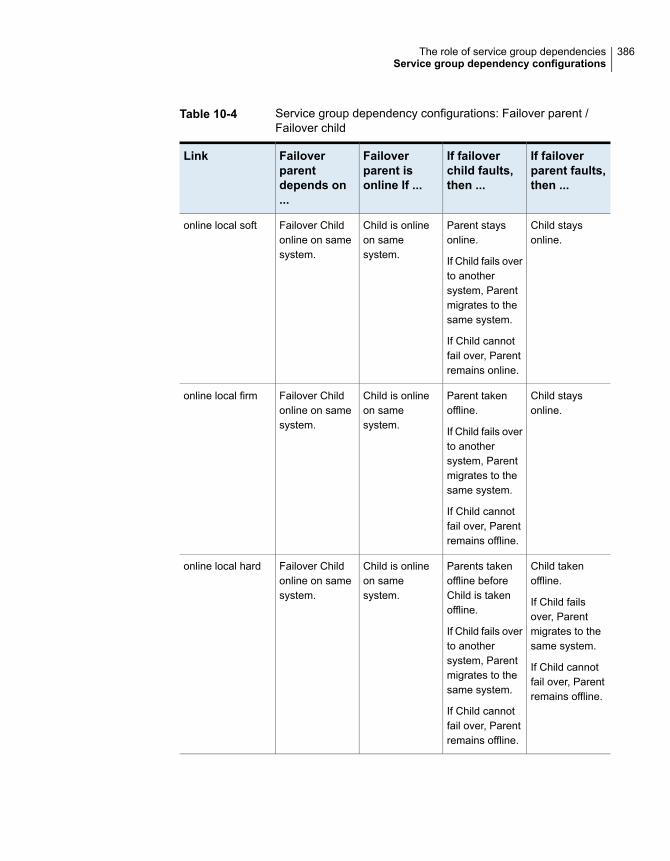
Table 10-4 Service group dependency configurations: Failover parent /Failover child
If failoverparent faults,then ...
If failoverchild faults,then ...
Failoverparent isonline If ...
Failoverparentdepends on...
Link
Child staysonline.
Parent staysonline.
If Child fails overto anothersystem, Parentmigrates to thesame system.
If Child cannotfail over, Parentremains online.
Child is onlineon samesystem.
Failover Childonline on samesystem.
online local soft
Child staysonline.
Parent takenoffline.
If Child fails overto anothersystem, Parentmigrates to thesame system.
If Child cannotfail over, Parentremains offline.
Child is onlineon samesystem.
Failover Childonline on samesystem.
online local firm
Child takenoffline.
If Child failsover, Parentmigrates to thesame system.
If Child cannotfail over, Parentremains offline.
Parents takenoffline beforeChild is takenoffline.
If Child fails overto anothersystem, Parentmigrates to thesame system.
If Child cannotfail over, Parentremains offline.
Child is onlineon samesystem.
Failover Childonline on samesystem.
online local hard
386The role of service group dependenciesService group dependency configurations

Table 10-4 Service group dependency configurations: Failover parent /Failover child (continued)
If failoverparent faults,then ...
If failoverchild faults,then ...
Failoverparent isonline If ...
Failoverparentdepends on...
Link
Child staysonline.
Parent fails overto any availablesystem.
If no failovertarget system isavailable, Parentremains offline.
Parent staysonline.
If Child fails overto anothersystem, Parentremains online.
If Child cannotfail over, Parentremains online.
Child is onlinesomewhere inthe cluster.
Failover Childonlinesomewhere inthe cluster.
online global soft
Child staysonline.
Parent fails overto any availablesystem.
If no failovertarget system isavailable, Parentremains offline.
Parent takenoffline afterChild is takenoffline.
If Child fails overto anothersystem, Parentis brought onlineon any system.
If Child cannotfail over, Parentremains offline.
Child is onlinesomewhere inthe cluster.
Failover Childonlinesomewhere inthe cluster.
online global firm
387The role of service group dependenciesService group dependency configurations
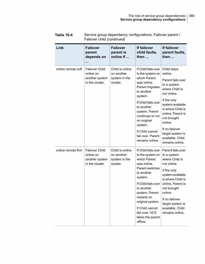
Table 10-4 Service group dependency configurations: Failover parent /Failover child (continued)
If failoverparent faults,then ...
If failoverchild faults,then ...
Failoverparent isonline If ...
Failoverparentdepends on...
Link
Child staysonline.
Parent fails overto a systemwhere Child isnot online.
If the onlysystem availableis where Child isonline, Parent isnot broughtonline.
If no failovertarget system isavailable, Childremains online.
If Child fails overto the system onwhich Parentwas online,Parent migratesto anothersystem.
If Child fails overto anothersystem, Parentcontinues to runon originalsystem.
If Child cannotfail over, Parentremains online.
Child is onlineon anothersystem in thecluster.
Failover Childonline onanother systemin the cluster.
online remote soft
Parent fails overto a systemwhere Child isnot online.
If the onlysystem availableis where Child isonline, Parent isnot broughtonline.
If no failovertarget system isavailable, Childremains online.
If Child fails overto the system onwhich Parentwas online,Parent switchesto anothersystem.
If Child fails overto anothersystem, Parentrestarts onoriginal system.
If Child cannotfail over, VCStakes the parentoffline.
Child is onlineon anothersystem in thecluster.
Failover Childonline onanother systemin the cluster.
online remote firm
388The role of service group dependenciesService group dependency configurations

Table 10-4 Service group dependency configurations: Failover parent /Failover child (continued)
If failoverparent faults,then ...
If failoverchild faults,then ...
Failoverparent isonline If ...
Failoverparentdepends on...
Link
Child remainsonline.
Parent fails overto anothersystem in thesame sitemaintainingdependency onChild instancesin the same site.
If Parent cannotfailover to asystem withinthe same site,then Parent failsover to a systemin another sitewhere at leastone instance ofchild is online inthe same site.
Parent staysonline.
If another Childinstance isonline or Childfails over to asystem withinthe same site,Parent staysonline.
If Child fails overto a system inanother site,parent migratesto another sitewhere Child isonline anddepends onChild instance(s)in that site.
If Child cannotfail over, Parentremains online.
Child is online inthe same site.
Failover Childonline on samesite.
online site soft
389The role of service group dependenciesService group dependency configurations

Table 10-4 Service group dependency configurations: Failover parent /Failover child (continued)
If failoverparent faults,then ...
If failoverchild faults,then ...
Failoverparent isonline If ...
Failoverparentdepends on...
Link
Child remainsonline.
Parent fails overto anothersystem in samesite maintainingdependence onChild instancesin the same site.
If Parent cannotfailover to asystem withinsame site, thenParent fails overto a system inanother sitewhere at leastone instance ofchild is online.
Parent takenoffline.
If anotherinstance of childis online in thesame site orchild fails over toanother systemin the same site,Parent migratesto a system inthe same site.
If no Childinstance isonline or Childcannot fail over,Parent remainsoffline.
Child is online inthe same site.
Failover Childonline in thesame site
online site firm
390The role of service group dependenciesService group dependency configurations

Table 10-4 Service group dependency configurations: Failover parent /Failover child (continued)
If failoverparent faults,then ...
If failoverchild faults,then ...
Failoverparent isonline If ...
Failoverparentdepends on...
Link
Parent fails overto system onwhich Child isnot online.
If no failovertarget system isavailable, Childremains online.
If Child fails overto the system onwhich parent innot running,parent continuesrunning.
If child fails overto system onwhich parent isrunning, parentswitches toanother system,if available.
If no failovertarget system isavailable forChild to fail overto, Parentcontinuesrunning.
Child is offlineon the samesystem.
Failover Childoffline on thesame system
offline local
About failover parent / parallel childWith a failover parent and parallel child, no hard dependencies are supported.
Table 10-5 shows service group dependency configurations for Failover parent /Parallel child.
391The role of service group dependenciesService group dependency configurations

Table 10-5 Service group dependency configurations: Failover parent /Parallel child
If failoverparent faults,then ...
If parallelchild faultson a system,then ...
Failoverparent isonline if ...
Failoverparentdepends on...
Link
Parent fails overto other systemand depends onChild instancethere.
Child Instanceremains onlinewhere theParent faulted.
If Child instancefails over toanother system,the Parent alsofails over to thesame system.
If Child instancecannot failoverto anothersystem, Parentremains online.
Instance of Childis online onsame system.
Instance ofparallel Childgroup on samesystem.
online local soft
Parent fails overto other systemand depends onChild instancethere.
Child Instanceremains onlinewhere Parentfaulted.
Parent is takenoffline. Parentfails over toother systemand depends onChild instancethere.
Instance of Childis online onsame system.
Instance ofparallel Childgroup on samesystem.
online local firm
Parent fails overto anothersystem,maintainingdependence onall Childinstances.
Parent remainsonline if Childfaults on anysystem.
If Child cannotfail over toanother system,Parent remainsonline.
At least oneinstance of Childgroup is onlinesomewhere inthe cluster.
All instances ofparallel Childgroup online inthe cluster.
online global soft
392The role of service group dependenciesService group dependency configurations

Table 10-5 Service group dependency configurations: Failover parent /Parallel child (continued)
If failoverparent faults,then ...
If parallelchild faultson a system,then ...
Failoverparent isonline if ...
Failoverparentdepends on...
Link
Parent fails overto anothersystem,maintainingdependence onall Childinstances.
Parent is takenoffline.
If another Childinstance isonline or Childfails over,Parent fails overto anothersystem or thesame system.
If no Childinstance isonline or Childcannot fail over,Parent remainsoffline.
An instance ofChild group isonlinesomewhere inthe cluster.
One or moreinstances ofparallel Childgroup remainingonline
online global firm
Parent fails overto anothersystem,maintainingdependence onthe Childinstances.
Parent remainsonline.
If Child fails overto the system onwhich Parent isonline, Parentfails over toanother system.
One or moreinstances ofChild group areonline on othersystems.
One or moreinstancesparallel Childgroup remainingonline on othersystems.
online remote soft
393The role of service group dependenciesService group dependency configurations

Table 10-5 Service group dependency configurations: Failover parent /Parallel child (continued)
If failoverparent faults,then ...
If parallelchild faultson a system,then ...
Failoverparent isonline if ...
Failoverparentdepends on...
Link
Parent fails overto anothersystem,maintainingdependence onall Childinstances.
Parent is takenoffline.
If Child fails overto the system onwhich Parent isonline, Parentfails over toanother system.
If Child fails overto anothersystem, Parentis brought onlineon its originalsystem.
All instances ofChild group areonline on othersystems.
All instancesparallel Childgroup remainingonline on othersystems.
online remote firm
Child staysonline.
Parents failsover to a systemwith Child onlinein the same site.
If the parentgroup cannotfailover, childgroup remainsonline
Parent staysonline if child isonline on anysystem in thesame site.
If Child fails overto a system inanother site,Parent stays inthe same site.
If Child cannotfail over, Parentremains online.
At least oneinstance of Childis online in samesite.
One or moreinstances ofparallel Childgroup in thesame site.
online site soft
394The role of service group dependenciesService group dependency configurations

Table 10-5 Service group dependency configurations: Failover parent /Parallel child (continued)
If failoverparent faults,then ...
If parallelchild faultson a system,then ...
Failoverparent isonline if ...
Failoverparentdepends on...
Link
Child staysonline.
Parents failsover to a systemwith Child onlinein the same site.
If the parentgroup cannotfailover, childgroup remainsonline.
Parent staysonline if anyinstance of childis online in thesame site.
If Child fails overto anothersystem, Parentmigrates to asystem in thesame site.
If Child cannotfail over, Parentremains offline.
At least oneinstance of Childis online in samesite.
One or moreinstances ofparallel Childgroup in thesame site.
online site firm
Child remainsonline andparent fails overto anothersystem wherechild is notonline.
If the parentgroup cannotfailover, childgroup remainsoffline.
Parent remainsonline if Childfails over toanother system.
If Child fails overto the system onwhich Parent isonline, Parentfails over.
No instance ofChild is onlineon samesystem.
Parallel Childoffline on samesystem.
offline local
About parallel parent / failover childTable 10-6 shows service group dependencies for parallel parent / failover child.
Online local dependencies between parallel parent groups and failover child groupsare not supported.
395The role of service group dependenciesService group dependency configurations

Table 10-6 Service group dependency configurations: Parallel parent /Failover child
If parallelparent faults,then ...
If failoverchild faultson a system,then ...
Parallelparentinstances areonline if ...
Parallelparentinstancesdepend on ...
Link
Child remainsonline
Parent remainsonline.
Failover Child isonlinesomewhere inthe cluster.
Failover Childgroup onlinesomewhere inthe cluster.
online global soft
Child staysonline.
All instances ofParent takenoffline.
After Child failsover, Parentinstances arefailed over orrestarted on thesame systems.
Failover Child isonlinesomewhere inthe cluster.
Failover Childgroupsomewhere inthe cluster.
online global firm
Child remainsonline. Parenttries to fail overto anothersystem wherechild is notonline.
If Child fails overto system onwhich Parent isonline, Parentfails over toother systems.
If Child fails overto anothersystem, Parentremains online.
Failover Child isonline onanother system.
Failover Childgroup onanother system.
online remote soft
396The role of service group dependenciesService group dependency configurations

Table 10-6 Service group dependency configurations: Parallel parent /Failover child (continued)
If parallelparent faults,then ...
If failoverchild faultson a system,then ...
Parallelparentinstances areonline if ...
Parallelparentinstancesdepend on ...
Link
Child remainsonline. Parenttries to fail overto anothersystem wherechild is notonline.
All instances ofParent takenoffline.
If Child fails overto system onwhich Parentwas online,Parent fails overto othersystems.
If Child fails overto anothersystem, Parentbrought onlineon samesystems.
Failover Child isonline onanother system.
Failover Childgroup onanother system.
online remote firm
Child remainsonline.
Parent remainsonline if Childfails over toanother system.
Child fails overto anothersystem. IfParent is onlineon that system,Parent isbrought offline.Parent fails overto any othersystem.
Failover Child isnot online onsame system.
Failover Childoffline on samesystem.
offline local
About parallel parent / parallel childGlobal and remote dependencies between parallel parent groups and parallel childgroups are not supported.
397The role of service group dependenciesService group dependency configurations

Table 10-7 shows service group dependency configurations for parallel parent /parallel child.
Table 10-7 Service group dependency configurations: Parallel parent /Parallel child
If parallelparent faults,then ...
If parallelchild faults,then ...
Parallelparent isonline If ...
Parallelparentdepends on...
Link
Child instancestays online.
Parent instancecan fail overonly to systemwhere Childinstance isrunning andother instance ofParent is notrunning.
If Child fails overto anothersystem, Parentmigrates to thesame system asthe Child.
If Child cannotfail over, Parentremains online.
Parallel Childinstance isonline on samesystem.
Parallel Childinstance onlineon samesystem.
online local soft
Child staysonline.
Parent instancecan fail overonly to systemwhere Childinstance isrunning andother instance ofParent is notrunning.
Parent takenoffline.
If Child fails overto anothersystem, VCSbrings aninstance of theParent online onthe samesystem as Child.
If Child cannotfail over, Parentremains offline.
Parallel Childinstance isonline on samesystem.
Parallel Childinstance onlineon samesystem.
online local firm
398The role of service group dependenciesService group dependency configurations

Table 10-7 Service group dependency configurations: Parallel parent /Parallel child (continued)
If parallelparent faults,then ...
If parallelchild faults,then ...
Parallelparent isonline If ...
Parallelparentdepends on...
Link
Child remainsonline.
Parent fails overto a systemwhere Child isnot online.
Parent remainsonline if Childfails over toanother system.
Parent goesoffline if Childfails over to asystem whereParent is online.Parent fails overto anothersystem whereChild is notonline.
No instance ofChild is onlineon samesystem.
Parallel Childoffline on samesystem.
offline local
Frequently asked questions about groupdependencies
Table 10-8 lists some commonly asked questions about group dependencies.
Table 10-8 Frequently asked questions about group dependencies
Frequently asked questionsDependency
Can child group be taken offline when parent group is online?
Soft=Yes Firm=No Hard = No.
Can parent group be switched while child group is online?
Soft=No Firm=No Hard = No.
Can child group be switched while parent group is online?
Soft=No Firm=No Hard = No.
Online local
399The role of service group dependenciesFrequently asked questions about group dependencies

Table 10-8 Frequently asked questions about group dependencies(continued)
Frequently asked questionsDependency
Can child group be taken offline when parent group is online?
Soft=Yes Firm=No.
Can parent group be switched while child group is running?
Soft=Yes Firm=Yes.
Can child group be switched while parent group is running?
Soft=Yes Firm=No
Online global
Can child group be taken offline when parent group is online?
Soft=Yes Firm=No.
Can parent group be switched while child group is running?
Soft=Yes, but not to system on which child is running.
Firm=Yes, but not to system on which child is running.
Can child group be switched while parent group is running?
Soft=Yes Firm=No, but not to system on which parent is running.
Online remote
Can parent group be brought online when child group is offline?
Yes.
Can child group be taken offline when parent group is online?
Yes.
Can parent group be switched while the child group is running?
Yes, but not to system on which child is running.
Can child group be switched while the parent group is running?
Yes, but not to system on which parent is running.
Offline local
Can child group be taken offline when parent group is online?
Soft=Yes Firm=No.
Can parent group be switched to a system in the same site while childgroup is running?
Soft=Yes Firm=Yes.
Can child group be switched while parent group is running?
Soft=Yes Firm=No
Online site
400The role of service group dependenciesFrequently asked questions about group dependencies

About linking service groupsNote that a configuration may require that a certain service group be running beforeanother service group can be brought online. For example, a group containingresources of a database service must be running before the database applicationis brought online.
Use the following command to link service groups from the command line
hagrp -link parent_group child_group gd_category gd_location [gd_type]
Name of the parent groupparent_group
Name of the child groupchild_group
category of group dependency (online/offline).gd_category
the scope of dependency (local/global/remote/site).gd_location
type of group dependency (soft/firm/hard). Default is firmgd_type
About linking multiple child service groupsVCS lets you configure multiple child service groups for a single parent servicegroup to depend on. For example, an application might depend on two or moredatabases.
Dependencies supported for multiple child service groupsMultiple child service groups can be linked to a parent service group using soft andfirm type of dependencies. Hard dependencies and offline local dependencies arenot supported
The supported dependency relationships between a parent service group andmultiple child service groups include:
■ Soft dependencyAll child groups can be online local soft.
■ Firm dependencyAll child groups can be online local firm.
■ A combination of soft and firm dependenciesSome child groups can be online local soft and other child groups can be onlinelocal firm.
401The role of service group dependenciesAbout linking service groups

■ A combination of local, global, remote, and site dependenciesOne child group can be online local soft, another child group can be onlineremote soft, and yet another child group can be online global firm.
Dependencies not supported for multiple child service groupsMultiple child service groups cannot be linked to a parent service group using offlinelocal and online local hard dependencies. Moreover, these dependencies cannotbe used with other dependency types.
A few examples of dependency relationships that are not supported between aparent service group and multiple child service groups:
■ A configuration in which multiple child service groups are offline local.
■ A configuration in which multiple child service groups are online local hard.
■ Any combination of offline local and other dependency typesYou cannot have a combination of offline local and online local soft or acombination of offline local and online local hard.
■ Any combination of online local hard and other dependency typesYou cannot have a combination of online local hard and online local soft.
VCS behavior with service group dependenciesVCS enables or restricts service group operations to honor service groupdependencies. VCS rejects operations if the operation violates a group dependency.
Online operations in group dependenciesTypically, bringing a child group online manually is never rejected, except underthe following circumstances:
■ For online local dependencies, if parent is online, a child group online is rejectedfor any system other than the system where parent is online.
■ For online remote dependencies, if parent is online, a child group online isrejected for the system where parent is online.
■ For offline local dependencies, if parent is online, a child group online is rejectedfor the system where parent is online.
The following examples describe situations where bringing a parallel child grouponline is accepted:
■ For a parallel child group linked online local with failover/parallel parent, multipleinstances of child group online are acceptable.
402The role of service group dependenciesVCS behavior with service group dependencies

■ For a parallel child group linked online remote with failover parent, multipleinstances of child group online are acceptable, as long as child group does notgo online on the system where parent is online.
■ For a parallel child group linked offline local with failover/parallel parent, multipleinstances of child group online are acceptable, as long as child group does notgo online on the system where parent is online.
Offline operations in group dependenciesVCS rejects offline operations if the procedure violates existing group dependencies.Typically, firm dependencies are more restrictive to taking child group offline whileparent group is online. Rules for manual offline include:
■ Parent group offline is never rejected.
■ For all soft dependencies, child group can go offline regardless of the state ofparent group.
■ For all firm dependencies, if parent group is online, child group offline is rejected.
■ For the online local hard dependency, if parent group is online, child group offlineis rejected.
Switch operations in group dependenciesSwitching a service group implies manually taking a service group offline on onesystem, and manually bringing it back online on another system. VCS rejects manualswitch if the group does not comply with the rules for offline or online operations.
403The role of service group dependenciesVCS behavior with service group dependencies

Administration - Beyond thebasics
■ Chapter 11. VCS event notification
■ Chapter 12. VCS event triggers
■ Chapter 13. Virtual Business Services
4Section

VCS event notificationThis chapter includes the following topics:
■ About VCS event notification
■ Components of VCS event notification
■ About VCS events and traps
■ About monitoring aggregate events
■ About configuring notification
About VCS event notificationVCS provides a method for notifying important events such as resource or systemfaults to administrators or designated recipients. VCS includes a notifier component,which consists of the notifier process and the hanotify utility.
VCS supports SNMP consoles that can use an SNMP V2 MIB.
The notifier process performs the following tasks:
■ Receives notifications from HAD
■ Formats the notification
■ Generates an SNMP (V2) trap or sends an email to the designated recipient,or does both.
If you have configured owners for resources, groups, or for the cluster, VCS alsonotifies owners of the events that affect their resources. A resource owner is notifiedof resource-related events, a group owner of group-related events, and so on.
You can also configure persons other than owners as recipients of notificationsabout events of a resource, resource type, service group, system, or cluster. Theregistered recipients get notifications for the events that have a severity level that
11Chapter

is equal to or greater than the level specified. For example, if you configure recipientsfor notifications and specify the severity level as Warning, VCS notifies the recipientsabout events with the severity levels Warning, Error, and SevereError but not aboutevents with the severity level Information.
See “About attributes and their definitions” on page 654.
Figure 11-1 shows the severity levels of VCS events.
Table 11-1 VCS event severity levels
DenotesSeverity level
Critical errors that can lead to data loss or corruption; SevereError isthe highest severity level.
SevereError
FaultsError
Deviations from normal behaviorWarning
Important events that exhibit normal behavior; Information is the lowestseverity level.
Information
Note: Severity levels are case-sensitive.
Figure 11-1 VCS event notification: Severity levels
System A System B
notifier
SMTP Error
InformationSevereError
SMTPSNMP
SNMP
HAD HAD
SNMP traps are forwarded to the SNMP console. Typically, traps are predefinedfor events such as service group or resource faults. You can use the hanotify utilityto send additional traps.
406VCS event notificationAbout VCS event notification

Event messages and severity levelsWhen the VCS engine starts up, it queues all messages of severity Information andhigher for later processing.
When notifier connects, it communicates to HAD the lowest severity threshold levelcurrently defined for the SNMP option or for the SMTP option.
If notifier is started from the command line without specifying a severity level forthe SNMP console or SMTP recipients, notifier communicates the default severitylevel Warning to HAD. If notifier is configured under VCS control, severity must bespecified.
See the description of the NotifierMngr agent in the Cluster Server Bundled AgentsReference Guide.
For example, if the following severities are specified for notifier:
■ Warning for email recipient 1
■ Error for email recipient 2
■ SevereError for SNMP console
Notifier communicates the minimum severity, Warning, to HAD, which then queuesall messages labelled severity level Warning and greater.
Notifier ensures that recipients receive only the messages they are designated toreceive according to the specified severity level. However, until notifier communicatesthe specifications to HAD, HAD stores all messages, because it does not know theseverity the user has specified. This behavior prevents messages from being lostbetween the time HAD stores them and notifier communicates the specificationsto HAD.
About persistent and replicated message queueVCS includes a sophisticated mechanism for maintaining event messages, whichensures that messages are not lost. On each node, VCS queues messages to besent to the notifier process. This queue is persistent as long as VCS is running andthe contents of this queue remain the same on each node. If the notifier servicegroup fails, notifier is failed over to another node in the cluster. Because the messagequeue is consistent across nodes, notifier can resume message delivery from whereit left off even after failover.
How HAD deletes messagesThe VCS engine, HAD, stores messages to be sent to notifier. After every 180seconds, HAD tries to send all the pending notifications to notifier. When HADreceives an acknowledgement from notifier that a message is delivered to at least
407VCS event notificationAbout VCS event notification

one of the recipients, it deletes the message from its queue. For example, if twoSNMP consoles and two email recipients are designated, notifier sends anacknowledgement to HAD even if the message reached only one of the fourrecipients. If HAD does not get acknowledgement for some messages, it keeps onsending these notifications to notifier after every 180 seconds till it gets anacknowledgement of delivery from notifier. An error message is printed to the logfile when a delivery error occurs.
HAD deletes messages under the following conditions too:
■ The message has been in the queue for time (in seconds) specified inMessageExpiryInterval attribute (default value: one hour) and notifier is unableto deliver the message to the recipient.
■ The message queue is full and to make room for the latest message, the earliestmessage is deleted.
Components of VCS event notificationThis topic describes the notifier process and the hanotify utility.
About the notifier processThe notifier process configures how messages are received from VCS and howthey are delivered to SNMP consoles and SMTP servers. Using notifier, you canspecify notification based on the severity level of the events generating themessages. You can also specify the size of the VCS message queue, which is 30by default. You can change this value by modifying the MessageQueue attribute.
See the Cluster Server Bundled Agents Reference Guide for more informationabout this attribute.
When notifier is started from the command line, VCS does not control the notifierprocess. For best results, use the NotifierMngr agent that is bundled with VCS.Configure notifier as part of a highly available service group, which can then bemonitored, brought online, and taken offline.
For information about the agent, see the Cluster Server Bundled Agents ReferenceGuide.
Note that notifier must be configured in a failover group, not parallel, because onlyone instance of notifier runs in the entire cluster. Also note that notifier does notrespond to SNMP get or set requests; notifier is a trap generator only.
Notifier enables you to specify configurations for the SNMP manager and SMTPserver, including machine names, ports, community IDs, and recipients’ email
408VCS event notificationComponents of VCS event notification

addresses. You can specify more than one manager or server, and the severitylevel of messages that are sent to each.
Note: If you start the notifier outside of VCS control, use the absolute path of thenotifier in the command. VCS cannot monitor the notifier process if it is startedoutside of VCS control using a relative path.
Example of notifier commandFollowing is an example of a notifier command:
/opt/VRTSvcs/bin/notifier -s m=north -s
m=south,p=2000,l=Error,c=your_company
-t m=north,e="abc@your_company.com",l=SevereError
In this example, notifier:
■ Sends all level SNMP traps to north at the default SNMP port and communityvalue public.
■ Sends Warning traps to north.
■ Sends Error and SevereError traps to south at port 2000 and community valueyour_company.
■ Sends SevereError email messages to north as SMTP server at default portand to email recipient abc@your_company.com.
About the hanotify utilityThe hanotify utility enables you to construct user-defined messages. The utilityforwards messages to HAD, which stores them in its internal message queue. Alongwith other messages, user-defined messages are also forwarded to the notifierprocess for delivery to email recipients, SNMP consoles, or both.
Figure 11-2 shows the hanotify utility.
409VCS event notificationComponents of VCS event notification

Figure 11-2 hanotify utility
System A System B
notifierhanotify
hadhad
Example of hanotify commandFollowing is an example of hanotify command:
hanotify -i 1.3.6.1.4.1.1302.3.8.10.2.8.0.10 -l Warning -n
agentres -T 7 -t "custom agent" -o 4 -S sys1 -L mv -p
sys2 -P mv -c MyAgent -C 7 -O johndoe -m "Custom message"
In this example, the number 1.3.6.1.4.1.1302.3.8.10.2.8.0.10 is the OID (ObjectIdentifier) for the message being sent. Because it is a user-defined message, HADhas no way of knowing the OID associated with the SNMP trap corresponding tothis message. Users must provide the OID.
The message severity level is set to Warning. The affected systems are sys1 andsys2. Running this command generates a custom notification with the message"Custom message" for the resource agentres.
About VCS events and trapsThis topic lists the events that generate traps, email notification, or both. Note thatSevereError indicates the highest severity level, Information the lowest. Trapsspecific to global clusters are ranked from Critical, the highest severity, to Normal,the lowest.
Events and traps for clustersTable 11-2 shows events and traps for clusters.
410VCS event notificationAbout VCS events and traps

Table 11-2 Events and traps for clusters
DescriptionSeveritylevel
Event
The cluster is down because of afault.
ErrorCluster has faulted.
The connector on the local clusterlost its heartbeat connection to theremote cluster.
ErrorHeartbeat is down.
(Global Cluster Option)
Local cluster has complete snapshotof the remote cluster, indicating theremote cluster is in the RUNNINGstate.
InformationRemote cluster is in RUNNING state.
(Global Cluster Option)
The heartbeat between clusters ishealthy.
InformationHeartbeat is "alive."
(Global Cluster Option)
A user log on has been recognizedbecause a user logged on by ClusterManager, or because a haxxxcommand was invoked.
InformationUser has logged on to VCS.
Events and traps for agentsTable 11-3 depicts events and traps for agents.
Table 11-3 Events and traps for agents
DescriptionSeveritylevel
Event
The agent has faulted on one node in thecluster.
WarningAgent is faulted.
VCS is restarting the agent.InformationAgent is restarting
Events and traps for resourcesTable 11-4 depicts events and traps for resources.
411VCS event notificationAbout VCS events and traps

Table 11-4 Events and traps for resources
DescriptionSeveritylevel
Event
VCS cannot identify the state ofthe resource.
WarningResource state is unknown.
Monitoring mechanism for theresource has timed out.
WarningResource monitoring has timed out.
VCS cannot take the resourceoffline.
WarningResource is not going offline.
Used by agents to giveadditional information on thestate of a resource. A decline inthe health of the resource wasidentified during monitoring.
WarningHealth of cluster resource declined.
The resource was broughtonline on its own.
Warning (notfor firstprobe)
Resource went online by itself.
The resource has faulted onone node in the cluster.
ErrorResource has faulted.
The agent is restarting theresource.
InformationResource is being restarted by agent.
Used by agents to give extrainformation about state ofresource. An improvement inthe health of the resource wasidentified during monitoring.
InformationThe health of cluster resource improved.
412VCS event notificationAbout VCS events and traps

Table 11-4 Events and traps for resources (continued)
DescriptionSeveritylevel
Event
This trap is generated whenstatistical analysis for the timetaken by the monitor function ofan agent is enabled for theagent.
See “ VCS agent statistics”on page 558.
This trap is generated when theagent framework detects asudden change in the timetaken to run the monitorfunction for a resource. The trapinformation contains details of:
■ The change in time requiredto run the monitor function
■ The actual times that werecompared to deduce thischange.
WarningResource monitor time has changed.
The resource is in theadmin_wait state.
See “ About controlling Cleanbehavior on resource faults”on page 335.
ErrorResource is in ADMIN_WAIT state.
Events and traps for systemsTable 11-5 depicts events and traps for systems.
Table 11-5 Events and traps for systems
DescriptionSeveritylevel
Event
The hashadow process isrestarting the VCS engine.
WarningVCS is being restarted by hashadow.
One node running VCS isin jeopardy.
WarningVCS is in jeopardy.
413VCS event notificationAbout VCS events and traps

Table 11-5 Events and traps for systems (continued)
DescriptionSeveritylevel
Event
VCS is up on the firstnode.
InformationVCS is up on the first node in the cluster.
VCS is down because ofa fault.
SevereErrorVCS has faulted.
The cluster has a newnode that runs VCS.
InformationA node running VCS has joined cluster.
VCS has exited gracefullyfrom one node on which itwas previously running.
InformationVCS has exited manually.
The system’s CPU usageexceeded the Warningthreshold level set in theCPUThreshold attribute.
WarningCPU usage exceeded threshold on the system.
The system’s swap usageexceeded the Warningthreshold level set in theSwapThreshold attribute.
WarningSwap usage exceeded threshold on the system.
The system’s Memoryusage exceeded theWarning threshold levelset in theMemThresholdLevelattribute.
WarningMemory usage exceeded threshold on thesystem.
Events and traps for service groupsTable 11-6 depicts events and traps for service groups.
Table 11-6 Events and traps for service groups
DescriptionSeveritylevel
Event
The service group is offlinebecause of a fault.
ErrorService group has faulted.
414VCS event notificationAbout VCS events and traps

Table 11-6 Events and traps for service groups (continued)
DescriptionSeveritylevel
Event
A failover service group hasbecome online on more thanone node in the cluster.
SevereErrorService group concurrency violation.
Specified service group faultedon all nodes where groupcould be brought online. Thereare no nodes to which thegroup can fail over.
SevereErrorService group has faulted and cannot befailed over anywhere.
The service group is online.InformationService group is online
The service group is offline.InformationService group is offline.
VCS has autodisabled thespecified group because onenode exited the cluster.
InformationService group is autodisabled.
The service group is restarting.InformationService group is restarting.
VCS is taking the servicegroup offline on one node andbringing it online on another.
InformationService group is being switched.
The service group is restartingbecause a persistent resourcerecovered from a fault.
InformationService group restarting in response topersistent resource going online.
A concurrency violationoccurred for the global servicegroup.
SevereErrorThe global service group is online/partialon multiple clusters.
(Global Cluster Option)
The attributes ClusterList,AutoFailOver, and Parallel aremismatched for the sameglobal service group ondifferent clusters.
ErrorAttributes for global service groups aremismatched.
(Global Cluster Option)
SNMP-specific filesVCS includes two SNMP-specific files: vcs.mib and vcs_trapd, which are createdin:
/etc/VRTSvcs/snmp
415VCS event notificationAbout VCS events and traps

The file vcs.mib is the textual MIB for built-in traps that are supported by VCS. Loadthis MIB into your SNMP console to add it to the list of recognized traps.
The file vcs_trapd is specific to the HP OpenView Network Node Manager (NNM)SNMP console. The file includes sample events configured for the built-in SNMPtraps supported by VCS. To merge these events with those configured for SNMPtraps:
xnmevents -merge vcs_trapd
When you merge events, the SNMP traps sent by VCS by way of notifier aredisplayed in the HP OpenView NNM SNMP console.
Note: For more information on xnmevents, see the HP OpenView documentation.
Trap variables in VCS MIBTraps sent by VCS are reversible to SNMPv2 after an SNMPv2 to SNMPv1conversion.
For reversible translations between SNMPv1 and SNMPv2 trap PDUs, thesecond-last ID of the SNMP trap OID must be zero. This ensures that once youmake a forward translation (SNMPv2 trap to SNMPv1; RFC 2576 Section 3.2), thereverse translation (SNMPv1 trap to SNMPv2 trap; RFC 2576 Section 3.1) isaccurate.
The VCS notifier follows this guideline by using OIDs with second-last ID as zero,enabling reversible translations.
About severityIdThis variable indicates the severity of the trap being sent.
Table 11-7 shows the values that the variable severityId can take.
Table 11-7 Possible values of the variable severityId
Value in trap PDUSeverity level and description
0Information
Important events exhibiting normal behavior
1Warning
Deviation from normal behavior
416VCS event notificationAbout VCS events and traps

Table 11-7 Possible values of the variable severityId (continued)
Value in trap PDUSeverity level and description
2Error
A fault
3Severe Error
Critical error that can lead to data loss or corruption
EntityType and entitySubTypeThese variables specify additional information about the entity.
Table 11-8 shows the variables entityType and entitySubType.
Table 11-8 Variables entityType and entitySubType
Entity sub-typeEntity type
String. For example, disk.Resource
String
The type of the group (failover or parallel)
Group
String. For example, AIX 5.1.System
String
Type of the heartbeat
Heartbeat
StringVCS
StringGCO
String
The agent name
Agent name
About entityStateThis variable describes the state of the entity.
Table 11-9 shows the the various states.
417VCS event notificationAbout VCS events and traps

Table 11-9 Possible states
StatesEntity
■ User has logged into VCS■ Cluster has faulted■ Cluster is in RUNNING state
VCS states
■ Agent is restarting■ Agent has faulted
Agent states
■ Resource state is unknown■ Resource monitoring has timed out■ Resource is not going offline■ Resource is being restarted by agent■ Resource went online by itself■ Resource has faulted■ Resource is in admin wait state■ Resource monitor time has changed
Resources states
■ Service group is online■ Service group is offline■ Service group is auto disabled■ Service group has faulted■ Service group has faulted and cannot be failed over anywhere■ Service group is restarting■ Service group is being switched■ Service group concurrency violation■ Service group is restarting in response to persistent resource
going online■ Service group attribute value does not match corresponding
remote group attribute value■ Global group concurrency violation
Service group states
■ VCS is up on the first node in the Cluster■ VCS is being restarted by hashadow■ VCS is in jeopardy■ VCS has faulted■ A node running VCS has joined cluster■ VCS has exited manually■ CPU usage exceeded the threshold on the system■ Memory usage exceeded the threshold on the system■ Swap usage exceeded the threshold on the system
System states
418VCS event notificationAbout VCS events and traps

Table 11-9 Possible states (continued)
StatesEntity
■ Cluster has lost heartbeat with remote cluster■ Heartbeat with remote cluster is alive
GCO heartbeat states
About monitoring aggregate eventsThis topic describes how you can detect aggregate events by monitoring individualnotifications.
How to detect service group failoverVCS does not send any explicit traps when a failover occurs in response to a servicegroup fault. When a service group faults, VCS generates the following notificationsif the AutoFailOver attribute for the service group is set to 1:
■ Service Group Fault for the node on which the service group was online andfaulted
■ Service Group Offline for the node on which the service group faulted
■ Service Group Online for the node to which the service group failed over
How to detect service group switchWhen a service group is switched, VCS sends a notification of severity Informationto indicate the following events:
■ Service group is being switched.
■ Service group is offline for the node from which the service group is switched.
■ Service group is online for the node to which the service group was switched.This notification is sent after VCS completes the service group switch operation.
Note: You must configure appropriate severity for the notifier to receive thesenotifications. To receive VCS notifications, the minimum acceptable severity levelis Information.
About configuring notificationConfiguring notification involves creating a resource for the Notifier Manager(NotifierMgr) agent in the ClusterService group.
419VCS event notificationAbout monitoring aggregate events

See the Cluster Server Bundled Agents Reference Guide for more informationabout the agent.
VCS provides several methods for configuring notification:
■ Manually editing the main.cf file.
■ Using the Notifier wizard.
420VCS event notificationAbout configuring notification
VCS event triggersThis chapter includes the following topics:
■ About VCS event triggers
■ Using event triggers
■ List of event triggers
About VCS event triggersTriggers let you invoke user-defined scripts for specified events in a cluster.
VCS determines if the event is enabled and invokes the hatrigger script. Thescript is located at:
$VCS_HOME/bin/hatrigger
VCS also passes the name of the event trigger and associated parameters. Forexample, when a service group comes online on a system, VCS invokes the followingcommand:
hatrigger -postonline system service_group
VCS does not wait for the trigger to complete execution. VCS calls the trigger andcontinues normal operation.
VCS invokes event triggers on the system where the event occurred, with thefollowing exceptions:
■ VCS invokes the sysoffline and nofailover event triggers on the lowest-numberedsystem in the RUNNING state.
■ VCS invokes the violation event trigger on all systems on which the servicegroup was brought partially or fully online.
12Chapter

By default, the hatrigger script invokes the trigger script(s) from the default path$VCS_HOME/bin/triggers. You can customize the trigger path by using theTriggerPath attribute.
See “Resource attributes” on page 655.
See “Service group attributes” on page 680.
The same path is used on all nodes in the cluster. The trigger path must exist onall the cluster nodes. On each cluster node, the trigger scripts must be installed inthe trigger path.
Using event triggersVCS provides a sample Perl script for each event trigger at the following location:
$VCS_HOME/bin/sample_triggers/VRTSvcs
Customize the scripts according to your requirements: you may choose to writeyour own Perl scripts.
To use an event trigger
1 Use the sample scripts to write your own custom actions for the trigger.
2 Move the modified trigger script to the following path on each node:
$VCS_HOME/bin/triggers
3 Configure other attributes that may be required to enable the trigger. See theusage information for the trigger for more information.
Performing multiple actions using a triggerTo perform multiple actions by using a trigger, specify the actions in the followingformat:
TNumService
Example: T1clear_env, T2update_env, T5backup
VCS executes the scripts in the ascending order of Tnum. The actions must beplaced inside a directory whose name is the trigger name. For example, to performmultiple actions for the postonline trigger, place the scripts in a directory namedpostonline.
Note: As a good practice, ensure that one script does not affect the functioning ofanother script. If script2 takes the output of script1 as an input, script2 must becapable of handling any exceptions that arise out of the behavior of script1.
422VCS event triggersUsing event triggers

Warning: Do not install customized trigger scripts in the$VCS_HOME/bin/sample_triggers/VRTSvcs directory or in the$VCS_HOME/bin/internal_triggers directory. If you install customized triggers inthese directories, you might face issues while upgrading VCS.
List of event triggersThe information in the following sections describes the various event triggers,including their usage, parameters, and location.
About the dumptunables triggerThe following table describes the dumptunables event trigger:
The dumptunables trigger is invoked when HAD goes into the RUNNING state.When this trigger is invoked, it uses the HAD environment variables that itinherited, and other environment variables to process the event. Depending onthe value of the to_log parameter, the trigger then redirects the environmentvariables to either stdout or the engine log.
This trigger is not invoked when HAD is restarted by hashadow.
This event trigger is internal and non-configurable.
Description
-dumptunables triggertype system to_log
triggertype—represents whether trigger is custom (triggertype=0) or internal(triggertype=1).
For this trigger, triggertype=0.
system—represents the name of the system on which the trigger is invoked.
to_log—represents whether the output is redirected to engine log (to_log=1) orstdout (to_log=0).
Usage
About the globalcounter_not_updated triggerThe following table describes the globalcounter_not_updated event trigger:
On the system having lowest NodeId in the cluster, VCS periodically broadcastsan update of GlobalCounter. If a node does not receive the broadcast for aninterval greater than CounterMissTolerance, it invokes theglobalcounter_not_updated trigger if CounterMissAction is set to Trigger. Thisevent is considered critical since it indicates a problem with underlying clustercommunications or cluster interconnects. Use this trigger to notify administratorsof the critical events.
Description
423VCS event triggersList of event triggers

-globalcounter_not_updated triggertype system_nameglobal_counter
triggertype—represents whether trigger is custom (triggertype=0) or internal(triggertype=1).
For this trigger, triggertype=0.
system—represents the system which did not receive the update ofGlobalCounter.
global_counter—represents the value of GlobalCounter.
Usage
About the injeopardy event triggerThe following table describes the injeopardy event trigger:
Invoked when a system is in jeopardy. Specifically, this trigger is invokedwhen a system has only one remaining link to the cluster, and that linkis a network link (LLT). This event is considered critical because if thesystem loses the remaining network link, VCS does not fail over theservice groups that were online on the system. Use this trigger to notifythe administrator of the critical event. The administrator can then takeappropriate action to ensure that the system has at least two links tothe cluster.
This event trigger is non-configurable.
Description
-injeopardy triggertype system system_state
triggertype—represents whether trigger is custom (triggertype=0) orinternal (triggertype=1).
For this trigger, triggertype=0.
system—represents the name of the system.
system_state—represents the value of the State attribute.
Usage
About the loadwarning event triggerThe following table describes the loadwarning event trigger:
424VCS event triggersList of event triggers

Invoked when a system becomes overloaded because the load of thesystem’s online groups exceeds the system’s LoadWarningLevelattribute for an interval exceeding the LoadTimeThreshold attribute.
For example, assume that the Capacity is 150, the LoadWarningLevelis 80, and the LoadTimeThreshold is 300. Also, the sum of the Loadattribute for all online groups on the system is 135. Because theLoadWarningLevel is 80, safe load is 0.80*150=120. The trigger isinvoked if the system load stays at 135 for more than 300 secondsbecause the actual load is above the limit of 120 specified byLoadWarningLevel.
Use this trigger to notify the administrator of the critical event. Theadministrator can then switch some service groups to another system,ensuring that no one system is overloaded.
This event trigger is non-configurable.
Description
-loadwarning triggertype system available_capacity
triggertype—represents whether trigger is custom (triggertype=0) orinternal (triggertype=1).
For this trigger, triggertype=0.
system—represents the name of the system.
available_capacity—represents the system’s AvailableCapacity attribute.(AvailableCapacity=Capacity-sum of Load for system’s online groups.)
Usage
About the multinicb event triggerThe following table describes the multinicb event trigger:
Invoked when a network device that is configured as a MultiNICBresource changes its state. The trigger is also always called in the firstmonitor cycle.
VCS provides a sample trigger script for your reference. You cancustomize the sample script according to your requirements.
Description
425VCS event triggersList of event triggers

-multinicb_postchange triggertype resource-namedevice-name previous-state current-statemonitor_heartbeat
triggertype—represents whether trigger is custom (triggertype=0) orinternal (triggertype=1).
For this trigger, triggertype=0.
resource-name—represents the MultiNICB resource that invoked thistrigger.
device-name—represents the network interface device for which thetrigger is called.
previous-state—represents the state of the device before the change.The value 1 indicates that the device is up; 0 indicates it is down.
current-state—represents the state of the device after the change.
monitor-heartbeat—an integer count, which is incremented in everymonitor cycle. The value 0 indicates that the monitor routine is calledfor first time.
Usage
About the nofailover event triggerThe following table describes the nofailover event trigger:
Called from the lowest-numbered system in RUNNING state when aservice group cannot fail over.
This event trigger is non-configurable.
Description
-nofailover triggertype system service_group
triggertype—represents whether trigger is custom (triggertype=0) orinternal (triggertype=1).
For this trigger, triggertype=0.
system—represents the name of the last system on which an attemptwas made to bring the service group online.
service_group—represents the name of the service group.
Usage
About the postoffline event triggerThe following table describes the postoffline event trigger:
426VCS event triggersList of event triggers

This event trigger is invoked on the system where the group went offlinefrom a partial or fully online state. This trigger is invoked when the groupfaults, or is taken offline manually.
This event trigger is non-configurable.
Description
-postoffline triggertype system service_group
triggertype—represents whether trigger is custom (triggertype=0) orinternal (triggertype=1).
For this trigger, triggertype=0.
system—represents the name of the system.
service_group—represents the name of the service group that wentoffline.
Usage
About the postonline event triggerThe following table describes the postonline event trigger:
This event trigger is invoked on the system where the group went onlinefrom an offline state.
This event trigger is non-configurable.
Description
-postonline triggertype system service_group
triggertype—represents whether trigger is custom (triggertype=0) orinternal (triggertype=1).
For this trigger, triggertype=0.
system—represents the name of the system.
service_group—represents the name of the service group that wentonline.
Usage
About the preonline event triggerThe following table describes the preonline event trigger:
427VCS event triggersList of event triggers

Indicates when the HAD should call a user-defined script before bringinga service group online in response to the hagrp -online commandor a fault.
If the trigger does not exist, VCS continues to bring the group online.If the script returns 0 without an exit code, VCS runs the hagrp-online -nopre command, with the -checkpartial option ifappropriate.
If you do want to bring the group online, define the trigger to take noaction. This event trigger is configurable.
Description
-preonline triggertype system service_groupwhyonlining [system_where_group_faulted]
triggertype—represents whether trigger is custom (triggertype=0) orinternal (triggertype=1).
For this trigger, triggertype=0.
system—represents the name of the system.
service_group—represents the name of the service group on which thehagrp command was issued or the fault occurred.
whyonlining—represents three values:
FAULT: Indicates that the group was brought online in response to agroup failover.
MANUAL: Indicates that group was brought online or switched manuallyon the system that is represented by the variable system.
SYSFAULT: Indicates that the group was brought online in responseto a sytem fault.
system_where_group_faulted—represents the name of the system onwhich the group has faulted or switched. This variable is optional andset when the engine invokes the trigger during a failover or switch.
Usage
Set the PreOnline attribute in the service group definition to 1.
You can set a local (per-system) value for the attribute to controlbehavior on each node in the cluster.
To enable thetrigger
Set the PreOnline attribute in the service group definition to 0.
You can set a local (per-system) value for the attribute to controlbehavior on each node in the cluster.
To disable thetrigger
About the resadminwait event triggerThe following table describes the resadminwait event trigger:
428VCS event triggersList of event triggers

Invoked when a resource enters ADMIN_WAIT state.
When VCS sets a resource in the ADMIN_WAIT state, it invokes theresadminwait trigger according to the reason the resource entered thestate.
See “Clearing resources in the ADMIN_WAIT state” on page 336.
This event trigger is non-configurable.
Description
-resadminwait system resource adminwait_reason
system—represents the name of the system.
resource—represents the name of the faulted resource.
adminwait_reason—represents the reason the resource entered theADMIN_WAIT state. Values range from 0-5:
0 = The offline function did not complete within the expected time.
1 = The offline function was ineffective.
2 = The online function did not complete within the expected time.
3 = The online function was ineffective.
4 = The resource was taken offline unexpectedly.
5 = The monitor function consistently failed to complete within theexpected time.
Usage
About the resfault event triggerThe following table describes the resfault event trigger:
Invoked on the system where a resource has faulted. Note that whena resource is faulted, resources within the upward path of the faultedresource are also brought down.
This event trigger is configurable.
To configure this trigger, you must define the following:
TriggerResFault: Set the attribute to 1 to invoke the trigger when aresource faults.
Description
429VCS event triggersList of event triggers

-resfault triggertype system resource previous_state
triggertype—represents whether trigger is custom (triggertype=0) orinternal (triggertype=1).
For this trigger, triggertype=0.
system—represents the name of the system.
resource—represents the name of the faulted resource.
previous_state—represents the resource’s previous state.
Usage
To invoke the trigger when a resource faults, set the TriggerResFaultattribute to 1.
To enable thetrigger
About the resnotoff event triggerThe following table describes the resnotoff event trigger:
Invoked on the system if a resource in a service group does not gooffline even after issuing the offline command to the resource.
This event trigger is configurable.
To configure this trigger, you must define the following:
Resource Name Define resources for which to invoke this trigger byentering their names in the following line in the script: @resources =("resource1", "resource2");
If any of these resources do not go offline, the trigger is invoked withthat resource name and system name as arguments to the script.
Description
-resnotoff triggertype system resource
triggertype—represents whether trigger is custom (triggertype=0) orinternal (triggertype=1).
For this trigger, triggertype=0.
system—represents the system on which the resource is not goingoffline.
resource—represents the name of the resource.
Usage
About the resrestart event triggerThe following table describes the resrestart event trigger.
This trigger is invoked when a resource is restarted by an agent because resourcefaulted and RestartLimit was greater than 0.
Description
430VCS event triggersList of event triggers
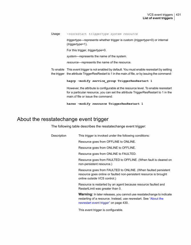
-resrestart triggertype system resource
triggertype—represents whether trigger is custom (triggertype=0) or internal(triggertype=1).
For this trigger, triggertype=0.
system—represents the name of the system.
resource—represents the name of the resource.
Usage
This event trigger is not enabled by default. You must enable resrestart by settingthe attribute TriggerResRestart to 1 in the main.cf file, or by issuing the command:
hagrp -modify service_group TriggerResRestart 1
However, the attribute is configurable at the resource level. To enable resrestartfor a particular resource, you can set the attribute TriggerResRestart to 1 in themain.cf file or issue the command:
hares -modify resource TriggerResRestart 1
To enablethe trigger
About the resstatechange event triggerThe following table describes the resstatechange event trigger:
This trigger is invoked under the following conditions:
Resource goes from OFFLINE to ONLINE.
Resource goes from ONLINE to OFFLINE.
Resource goes from ONLINE to FAULTED.
Resource goes from FAULTED to OFFLINE. (When fault is cleared onnon-persistent resource.)
Resource goes from FAULTED to ONLINE. (When faulted persistentresource goes online or faulted non-persistent resource is broughtonline outside VCS control.)
Resource is restarted by an agent because resource faulted andRestartLimit was greater than 0.
Warning: In later releases, you cannot use resstatechange to indicaterestarting of a resource. Instead, use resrestart. See “About theresrestart event trigger” on page 430.
This event trigger is configurable.
Description
431VCS event triggersList of event triggers

-resstatechange triggertype system resourceprevious_state new_state
triggertype—represents whether trigger is custom (triggertype=0) orinternal (triggertype=1).
For this trigger, triggertype=0.
system—represents the name of the system.
resource—represents the name of the resource.
previous_state—represents the resource’s previous state.
new_state—represents the resource’s new state.
Usage
This event trigger is not enabled by default. You must enableresstatechange by setting the attribute TriggerResStateChange to 1 inthe main.cf file, or by issuing the command:
hagrp -modify service_group TriggerResStateChange 1
Use the resstatechange trigger carefully. For example, enabling thistrigger for a service group with 100 resources means that 100 hatriggerprocesses and 100 resstatechange processes are fired each time thegroup is brought online or taken offline. Also, this is not a "wait-modetrigger. Specifically, VCS invokes the trigger and does not wait for triggerto return to continue operation.
However, the attribute is configurable at the resource level. To enableresstatechange for a particular resource, you can set the attributeTriggerResStateChange to 1 in the main.cf file or issue the command:
hares -modify resource TriggerResStateChange 1
To enable thetrigger
About the sysoffline event triggerThe following table describes the sysoffline event trigger:
Called from the lowest-numbered system in RUNNING state when asystem is in jeopardy state or leaves the cluster.
This event trigger is non-configurable.
Description
-sysoffline system system_state
system—represents the name of the system.
system_state—represents the value of the State attribute.
See “System states” on page 651.
Usage
432VCS event triggersList of event triggers

About the sysup triggerThe following table describes the sysup event trigger:
The sysup trigger is invoked when the first node joins the cluster.Description
-sysup triggertype system systemstate
For this trigger, triggertype = 0.
system— represents the system name.
systemstate—represents the state of the system.
Usage
About the sysjoin triggerThe following table describes the sysjoin event trigger:
The sysjoin trigger is invoked when a peer node joins the cluster.Description
-sysjoin triggertype system systemstate
For this trigger, triggertype = 0.
system—represents the system name.
systemstate—represents the state of the system.
Usage
About the unable_to_restart_agent event triggerThe following table describes the unable_to_restart_agent event trigger:
This trigger is invoked when an agent faults more than a predeterminednumber of times with in an hour. When this occurs, VCS gives up tryingto restart the agent. VCS invokes this trigger on the node where theagent faults.
You can use this trigger to notify the administrators that an agent hasfaulted, and that VCS is unable to restart the agent. The administratorcan then take corrective action.
Description
-unable_to_restart_agent system resource_type
system—represents the name of the system.
resource_type—represents the resource type associated with the agent.
Usage
Remove the files associated with the trigger from the$VCS_HOME/bin/triggers directory.
To disable thetrigger
433VCS event triggersList of event triggers

About the unable_to_restart_had event triggerThe following table describes the unable_to_restart_had event trigger:
This event trigger is invoked by hashadow when hashadow cannotrestart HAD on a system. If HAD fails to restart after six attempts,hashadow invokes the trigger on the system.
The default behavior of the trigger is to reboot the system. However,service groups previously running on the system are autodisabled whenhashadow fails to restart HAD. Before these service groups can bebrought online elsewhere in the cluster, you must autoenable them onthe system. To do so, customize the unable_to_restart_had trigger toremotely execute the following command from any node in the clusterwhere VCS is running:
hagrp -autoenable service_group -sys system
For example, if hashadow fails to restart HAD on system1, and if group1and group2 were online on that system, a trigger customized in thismanner would autoenable group1 and group2 on system1 beforerebooting. Autoenabling group1 and group2 on system1 enables thesetwo service groups to come online on another system when the triggerreboots system1.
This event trigger is non-configurable.
Description
-unable_to_restart_had
This trigger has no arguments.
Usage
About the violation event triggerThe following table describes the violation event trigger:
This trigger is invoked only on the system that caused the concurrencyviolation. Specifically, it takes the service group offline on the systemwhere the trigger was invoked. Note that this trigger applies to failovergroups only. The default trigger takes the service group offline on thesystem that caused the concurrency violation.
This event trigger is internal and non-configurable.
Description
-violation system service_group
system—represents the name of the system.
service_group—represents the name of the service group that was fullyor partially online.
Usage
434VCS event triggersList of event triggers

Virtual Business ServicesThis chapter includes the following topics:
■ About Virtual Business Services
■ Features of Virtual Business Services
■ Sample virtual business service configuration
■ About choosing between VCS and VBS level dependencies
About Virtual Business ServicesThe Virtual Business Services feature provides visualization, orchestration, andreduced frequency and duration of service disruptions for multi-tier businessapplications running on heterogeneous operating systems and virtualizationtechnologies. A virtual business service represents the multi-tier application as aconsolidated entity that helps you manage operations for a business service. Itbuilds on the high availability and disaster recovery provided for the individual tiersby Veritas InfoScale products such as Cluster Server.
Application components that are managed by Cluster Server or Microsoft FailoverClustering can be actively managed through a virtual business service.
You can use the Veritas InfoScale Operations Manager Management Server consoleto create, configure, and manage virtual business services.
Features of Virtual Business ServicesThe following VBS operations are supported:
■ Start Virtual Business Services from the Veritas InfoScale Operations Managerconsole: When a virtual business service starts, its associated service groupsare brought online.
13Chapter

■ Stop Virtual Business Services from the Veritas InfoScale Operations Managerconsole: When a virtual business service stops, its associated service groupsare taken offline.
■ Applications that are under the control of ApplicationHAcan be part of a virtualbusiness service. ApplicationHAenables starting, stopping, and monitoring ofan application within a virtual machine. If applications are hosted on VMwarevirtual machines, you can configure the virtual machines to automatically startor stop when you start or stop the virtual business service, provided the vCenterfor those virtual machines has been configured in Veritas InfoScale OperationsManager.
■ Define dependencies between service groups within a virtual business service:The dependencies define the order in which service groups are brought onlineand taken offline. Setting the correct order of service group dependency is criticalto achieve business continuity and high availability. You can define thedependency types to control how a tier reacts to high availability events in theunderlying tier. The configured reaction could be execution of a predefined policyor a custom script.
■ Manage the virtual business service from Veritas InfoScale Operations Manageror from the clusters participating in the virtual business service.
■ Recover the entire virtual business service to a remote site when a disasteroccurs.
Sample virtual business service configurationThis section provides a sample virtual business service configuration comprising amulti-tier application. Figure 13-1 shows a Finance application that is dependenton components that run on three different operating systems and on three differentclusters.
■ Databases such as Oracle running on Solaris operating systems form thedatabase tier.
■ Middleware applications such as WebSphere running on AIX operating systemsform the middle tier.
■ Web applications such as Apache and IIS running on Windows and Linux virtualmachines form the Web tier.Each tier can have its own high availability mechanism. For example, you canuse Cluster Server for the databases and middleware applications for the Webservers.
436Virtual Business ServicesSample virtual business service configuration

Figure 13-1 Sample virtual business service configuration
Each time you start the Finance business application, typically you need to bringthe components online in the following order – Oracle database, WebSphere,Apache and IIS. In addition, you must bring the virtual machines online before youstart the Web tier. To stop the Finance application, you must take the componentsoffline in the reverse order. From the business perspective, the Finance service isunavailable if any of the tiers becomes unavailable.
When you configure the Finance application as a virtual business service, you canspecify that the Oracle database must start first, followed by WebSphere and theWeb servers. The reverse order automatically applies when you stop the virtualbusiness service. When you start or stop the virtual business service, thecomponents of the service are started or stopped in the defined order.
437Virtual Business ServicesSample virtual business service configuration

For more information about Virtual Business Services, refer to the Virtual BusinessService–Availability User’s Guide.
About choosing between VCS and VBS leveldependencies
While a VBS typically has service groups across clusters, you can also have twoor more service groups from a single cluster participate in a given VBS. In this case,you can choose to configure either VCS dependency or VBS dependency betweenthese intra-cluster service groups. Veritas recommends use of VCS dependencyin this case. However, based on your requirement about the type of fault policydesired, you can choose appropriately. For information about VBS fault policies,refer to the Virtual Business Service–Availability User’s Guide.
See “Service group dependency configurations” on page 385.
438Virtual Business ServicesAbout choosing between VCS and VBS level dependencies

Veritas High AvailabilityConfiguration wizard
■ Chapter 14. Introducing the Veritas High Availability Configuration wizard
■ Chapter 15. Administering application monitoring from the Veritas High Availabilityview
5Section

Introducing the VeritasHigh AvailabilityConfiguration wizard
This chapter includes the following topics:
■ About the Veritas High Availability Configuration wizard
■ Launching the Veritas High Availability Configuration wizard
■ Typical VCS cluster configuration in a physical environment
About the Veritas High Availability Configurationwizard
The Veritas High Availability Configuration wizard can be used to configureapplications that use active-passive storage. Active-passive storage can accessonly one node at a time. Apart from configuring application availability, the wizardalso sets up other components (for example: networking, storage) required forsuccessful application monitoring.
Before you configure an application for monitoring, you must configure a cluster.You can use the VCS Cluster Configuration wizard to configure a cluster. Refer tothe VCS Installation Guide for the steps to configure a cluster.
You can use the Veritas High Availability Configuration wizard to configure theapplications listed in Table 14-1.
14Chapter

Table 14-1 Supported applications
Platform/Virtualization technologyApplication
■ AIX■ Linux■ Solaris
Generic application
VMware on LinuxOracle
VMware on LinuxSAP WebAS
VMware on LinuxWebSphere MQ
See “Launching the Veritas High Availability Configuration wizard” on page 441.
For information on the procedure to configure a particular application, refer to theapplication-specific agent guide.
Launching the Veritas High AvailabilityConfiguration wizard
In a physical Linux environment, VMware virtual environment, logical domain, orLPAR, you can launch the Veritas High Availability Configuration wizard using:
■ Client: To launch the wizard from the Client
■ A browser window: To launch the wizard from a browser window
In addition, in a Linux environment, you can also launch the wizard using:
■ haappwizard utility: To launch the wizard using the haappwizard utility
In addition, in a VMware virtual environment, you can also launch the wizard using:
■ VMware vSphere Client: To launch the wizard from the VMware vSphere Client
To launch the wizard from the Client
1 Log in to the Management Server console.
2 In the home page, click the Availability icon from the list of perspectives.
3 In the Data Center tree under the Manage pane, locate the cluster.
4 Navigate to the Systems object under the cluster.
5 Locate the system on which the application is running or applicationprerequisites are met.
6 Right-click on the system, and then click Configure Application.
441Introducing the Veritas High Availability Configuration wizardLaunching the Veritas High Availability Configuration wizard

To launch the wizard from a browser window
1 Open a browser window and enter the following URL:
https://system_name_or_IP:5634/vcs/admin/application_health.html
system_name_or_IP is the system name or IP address of the system on whichyou want to configure application monitoring.
2 In the Authentication dialog box, enter the username and password of the userwho has administrative privileges.
3 Depending on your setup, use one of the following options to launch the wizard:
■ If you have not configured a cluster, click the Configure a VCS Clusterlink.
■ If you have already configured a cluster, click Actions > ConfigureApplication for High Availability or the Configure Application for HighAvailability link.
■ If you have already configured a cluster and configured an application formonitoring, click Actions > Configure Application for High Availability.
Note: In the Storage Foundation and High Availability (SFHA) 6.2 release and later,the haappwizard utility has been deprecated.
To launch the wizard using the haappwizard utility
The haappwizard utility allows you to launch the Veritas High AvailabilityConfiguration wizard. The utility is part of the product package and is installed inthe /opt/VRTSvcs/bin directory.
◆ Enter the following command to launch the Veritas High AvailabilityConfiguration wizard:
happwizard [-hostname host_name] [-browser browser_name] [-help]
The following table describes the options of the happwizard utility:
Table 14-2 Options of the happwizard utility
Allows you to specify the host name or IP address of the systemfrom which you want to launch the Veritas High AvailabilityConfiguration wizard. If you do not specify a host name or IP address,the Veritas High Availability Configuration wizard is launched on thelocal host.
–hostname
442Introducing the Veritas High Availability Configuration wizardLaunching the Veritas High Availability Configuration wizard

Table 14-2 Options of the happwizard utility (continued)
Allows you to specify the browser name. The supported browsersare Internet Explorer and Firefox. For example, enter iexplore forInternet Explorer and firefox for Firefox.
Note: The value is case-insensitive.
-browser
Displays the command usage.-help
To launch the wizard from the VMware vSphere Client
1 Launch the VMware vSphere Client and connect to the VMware vCenter Serverthat hosts the virtual machine.
2 From the vSphere Client’s Inventory view in the left pane, select the virtualmachine where you want to configure application monitoring.
3 Skip this step if you have already configured single sign-on during guestinstallation.
Select the Veritas High Availability tab and in the Veritas High Availability Viewpage, specify the credentials of a user account that has administrative privilegeson the virtual machine and click Configure.
The Veritas High Availability console sets up a permanent authentication forthe user account on that virtual machine.
4 Depending on your setup, use one of the following options to launch the wizard:
■ If you have not configured a cluster, click the Configure a VCS Clusterlink.
■ If you have already configured a cluster, click Actions > ConfigureApplication for High Availability or the Configure Application for HighAvailability link.
■ If you have already configured a cluster and configured an application formonitoring and to configure another application for monitoring, clickActions> Configure Application for High Availability.
Typical VCS cluster configuration in a physicalenvironment
A typical VCS cluster configuration in a physical environment involves two or morephysical machines.
The application binaries are installed on a local or shared storage and the data filesshould be installed on a shared storage. The VCS agents monitor the application
443Introducing the Veritas High Availability Configuration wizardTypical VCS cluster configuration in a physical environment

components and services, and the storage and network components that theapplication uses.
Figure 14-1 Typical generic applications cluster configuration in a physicalenvironment
During a fault, the VCS storage agents fail over the storage to a new system. TheVCS network agents bring the network components online and theapplication-specific agents then start application services on the new system.
444Introducing the Veritas High Availability Configuration wizardTypical VCS cluster configuration in a physical environment

Administering applicationmonitoring from theVeritas High Availabilityview
This chapter includes the following topics:
■ Administering application monitoring from the Veritas High Availability view
■ Administering application monitoring settings
Administering application monitoring from theVeritas High Availability view
The Veritas High Availability view is a Web-based graphic user interface that youcan use to administer application availability with Cluster Server (VCS).
This interface supports physical and virtual systems running Linux, Solaris, andAIX operating systems. The interface supports virtual environments such as IBMPowerVM, Oracle VM Server for SPARC, Red Hat Enterprise Virtualization (RHEV),Kernel-based Virtual Machine (KVM), and VMware.
You can launch the Veritas High Availability view from an Internet browser, by usingthe following URL:
https://SystemNameorIP:5634/vcs/admin/application_health.html?priv=ADMINwhere SystemNameorIP is the system name or the IP address of the physical orvirtual system from where you want to access the tab.
15Chapter

In a VMware virtual environment, you can embed the Veritas High Availability viewas a tab in the vSphere Client menu (both the desktop and Web versions).
You can perform tasks such as start, stop, or fail over an application, without theneed for specialized training in VCS commands, operating systems, or virtualizationtechnologies. You can also perform advanced tasks such as VCS clusterconfiguration and application (high availability) configuration from this view, by usingsimple wizard-based steps.
Use the Veritas High Availability view to perform the following tasks:
■ To configure a VCS cluster
■ To add a system to a VCS cluster
■ To configure and unconfigure application monitoring
■ To unconfigure the VCS cluster
■ To start and stop configured applications
■ To add and remove failover systems
■ To enter and exit maintenance mode
■ To switch an application
■ To determine the state of an application (components)
■ To clear Fault state
■ To resolve a held-up operation
■ To modify application monitoring settings
■ To view application dependency
■ To view component dependency
Understanding the Veritas High Availability viewThe Veritas High Availability view displays the consolidated health information forapplications running in a Cluster Server (VCS) cluster. The cluster may include oneor more systems.
The Veritas High Availability tab displays application information for the entire VCScluster, not just the local system.
446Administering application monitoring from the Veritas High Availability viewAdministering application monitoring from the Veritas High Availability view

Note: If the local system is not part of any VCS cluster, then the Veritas ApplicationHigh Availability view displays only the following link: Configure a VCS cluster.
If you are yet to configure an application for monitoring in a cluster of which thelocal system is a member, then the Veritas Application High Availability view displaysonly the following link: Configure an application for high availability.
The Veritas High Availability view uses icons, color coding, dependency graphs,and tool tips to report the detailed status of an application.
The Veritas High Availability view displays complex applications, in terms of multipleinterdependent instances of that application. Such instances represent componentgroups (also known as service groups) of that application. Each service group inturn includes several critical components (resources) of the application.
The following figure shows the Veritas High Availability view, with one instance ofOracle Database and one instance of a generic application configured for highavailability in a two-node VCS cluster:
2. Actions menu1. Title bar
4. Application dependency graph3. Aggregate Status Bar
447Administering application monitoring from the Veritas High Availability viewAdministering application monitoring from the Veritas High Availability view

6. Application-specific task menu5.Application table
7. Component dependency graph
The Veritas High Availability view includes the following parts:
■ Title bar: Displays the name of the VCS cluster, the Actions menu, the Refreshicon, the Alert icon. Note that the Alert icon appears only if the Veritas HighAvailability view fails to display a system, or displays stale data.
■ Actions menu: Includes a drop-down list of operations that you can perform witheffect across the cluster. These include: Configuring a cluster, Configuring anapplication for high availability; Unconfigure all applications; and UnconfigureVCS cluster.
■ Aggregate status bar: Displays a summary of applications running in the cluster.This includes the total number of applications, and a breakdown of the numberof applications in Online, Offline, Partial, and Faulted states.
■ Application dependency graph: Illustrates the order in which the applications orapplication instances, must start or stop.If an application must start first for another application to successfully start, theearlier application appears at a lower level in the graph. A line connects the twoapplications to indicate the dependency. If no such dependency exists, allapplications appear in a single horizontal line.
■ Application table: Displays a list of all applications configured in the VCS clusterthat is associated with the local system.Each application is listed in a separate row. Each row displays the systemswhere the application is configured for monitoring.The title bar of each row displays the following entities to identify the applicationor application instance (service group):
■ Display name of the application (for example, Payroll application)
■ Type of application (for example, Custom)
■ Service group name
■ Application-specific task menu: Appears in each application-specific row of theapplication table. The menu includes application-specific tasks such as Start,Stop, Switch, and a dropdown list of more tasks. The More dropdown list includestasks such as Add a failover system, and Remove a failover system.
■ Component dependency graph: Illustrates the order in which applicationcomponents (resources) must start or stop for the related application orapplication instance to respectively start or stop. The component dependencygraph by default does not appear in the application table. To view the component
448Administering application monitoring from the Veritas High Availability viewAdministering application monitoring from the Veritas High Availability view

dependency graph for an application, you must click a system on which theapplication is running.The track pad, at the right-bottom corner helps you navigate through componentdependency graphs.If you do not want to view the component dependency graph, in the top leftcorner of the application row, click Close.
To view the status of configured applicationsIn the application dependency graph, click the application for which you want toview the status. If the appropriate row is not already visible, the application tableautomatically scrolls to the appropriate row. The row displays the state of theapplication for each configured failover system in the cluster for that application.
If you click any system in the row, a component dependency graph appears. Thegraph uses symbols, color code, and tool tips to display the health of each applicationcomponent. Roll the mouse over a system or component to see its health details.
The health of each application/application component on the selected system isdisplayed in terms of the following states:
Table 15-1 Application states
DescriptionState
Indicates that the configured application or application componentsare running on the system.
If the application is offline on at least one other failover system, analert appears next to the application name.
Online
Indicates that the configured application or its components are notrunning on the system.
Offline
Indicates that either the application or its components are beingstarted on the system or VCS was unable to start one or more of theconfigured components
If the application is offline on at least one other failover system, analert appears next to the application name.
Partial
Indicates that the configured application or its components haveunexpectedly stopped running.
Faulted
To configure or unconfigure application monitoringUse the Veritas High Availability view to configure or un-configure an applicationfor monitoring in a cluster under Cluster Server (VCS) control.
449Administering application monitoring from the Veritas High Availability viewAdministering application monitoring from the Veritas High Availability view

The view provides you with specific links to perform the following configurationtasks:
■ Configure a VCS cluster:If the local system is not part of a VCS cluster, the Veritas High Availability viewappears blank, except for the link Configure a VCS cluster.Before you can configure application monitoring, you must click the Configurea VCS cluster link to launch the VCS Cluster Configuration wizard. The wizardhelps you configure a VCS cluster, where the local system is by default a clustersystem.
■ Configure the first application for monitoring in a VCS cluster:If you have not configured any application for monitoring in the cluster, theVeritas High Availability view appears blank except for the link Configure anapplication for high availability.Click the link to launch the Veritas High Availability Configuration Wizard. Usethe wizard to configure application monitoring.Also, in applications where the Veritas High Availability Configuration Wizard issupported, for detailed wizard-based steps, see the application-specific VCSagent configuration guide. For custom applications, see the Cluster ServerGeneric Application Agent Configuration Guide.
■ Add a system to the VCS cluster:ClickActions >Add a System to VCSCluster to add a system to a VCS clusterwhere the local system is a cluster member. Adding a system to the cluster doesnot automatically add the system as a failover system for any configuredapplication. To add a system as a failover system, see (add a cross-referenceto 'To add or remove a failover system'.
■ Configure an application or add an application to the existing applicationmonitoring configuration:Click Actions > Configure an application for high availability to launch theVeritas High Availability Application Monitoring Configuration Wizard. Use thewizard to configure application monitoring.
■ Unconfigure monitoring of an application:In the appropriate row of the application table, click More > UnconfigureApplication Monitoring to delete the application monitoring configuration fromthe VCS.Note that this step does not remove VCS from the system or the cluster, thisstep only removes the monitoring configuration for that application.Also, to unconfigure monitoring for an application, you can perform one of thefollowing procedures: unconfigure monitoring of all applications, or unconfigureVCS cluster.
■ Unconfigure monitoring of all applications:
450Administering application monitoring from the Veritas High Availability viewAdministering application monitoring from the Veritas High Availability view

ClickActions >Unconfigure all applications. This step deletes the monitoringconfiguration for all applications configured in the cluster.
■ Unconfigure VCS cluster:Click Actions > Unconfigure VCS cluster. This step stops the VCS cluster,removes VCS cluster configuration, and unconfigures application monitoring.
To start or stop applicationsUse the following options on the Veritas High Availability view to control the statusof the configured application and the associated components or component groups(application instances).
Note that the Start and Stop links are dimmed in the following cases:
■ If you have not configured any associated components or component groups(resources or service groups) for monitoring
■ If the application is in maintenance mode
■ If no system exists in the cluster, where the application is not already started orstopped as required.
To start an application
1 In the appropriate row of the application table, click Start.
2 If the application (service group) is of the failover type, on the Start Applicationpanel, click Any system. VCS uses pre-defined policies to decide the systemwhere to start the application.
If the application (service group) is of the parallel type, on the Start Applicationpanel, click All systems. VCS starts the application on all required systems,where the service group is configured.
Note: Based on service group type, either the Any system or the All Systemslink automatically appears.
To learn more about policies, and parallel and failover service groups, see theCluster Server Administrator's Guide.
If you want to specify the system where you want to start the application, clickUser selected system, and then click the appropriate system.
3 If the application that you want to start requires other applications or componentgroups (service groups) to start in a specific order, then check the Start thedependent components in order check box, and then click OK.
451Administering application monitoring from the Veritas High Availability viewAdministering application monitoring from the Veritas High Availability view

To stop an application
1 In the appropriate row of the application table, click Stop.
2 If the application (service group) is of the failover type, in the Stop ApplicationPanel, click Any system. VCS selects the appropriate system to stop theapplication.
If the application (service group) is of the parallel type, in the Stop ApplicationPanel click All systems. VCS stops the application on all configured systems.
Note: Based on service group type, either the Any system or the All Systemslink automatically appears.
To learn more about parallel and failover service groups, see theCluster ServerAdministrator's Guide.
If you want to specify the system where you want to stop the application, clickUser selected system, and then click the appropriate system.
3 If the application that you want to stop requires other applications or componentgroups (service groups) to stop in a specific order, then check the Stop thedependent components in order check box, and then click OK.
To suspend or resume application monitoringAfter configuring application monitoring you may want to perform routinemaintenance tasks on those applications. These tasks may or may not involvestopping the application but may temporarily affect the state of the applications andits dependent components. If there is any change to the application status, ClusterServer (VCS) may try to restore the application state. This may potentially affectthe maintenance tasks that you intend to perform on those applications.
The Enter Maintenance Mode link is automatically dimmed if the application isalready in maintenance mode. Conversely, if the application is not in maintenancemode, the Exit Maintenance Mode link is dimmed.
The Veritas High Availability tab provides the following options:
452Administering application monitoring from the Veritas High Availability viewAdministering application monitoring from the Veritas High Availability view
To enter maintenance mode
1 In the appropriate row, click More> Enter Maintenance Mode.
During the time the monitoring is suspended, Veritas high availability solutionsdo not monitor the state of the application and its dependent components. TheVeritas High Availability view does not display the current status of theapplication. If there is any failure in the application or its components, VCStakes no action.
2 While in maintenance mode, if a virtual machine restarts, if you want applicationmonitoring to remain in maintenance mode, then in the Enter MaintenanceMode panel, check the Suspend the application availability even afterreboot check box, and then click OK to enter maintenance mode.
To exit the maintenance mode
1 In the appropriate row, click More> Exit Maintenance Mode, and then clickOK to exit maintenance mode.
2 Click the Refresh icon in the top right corner of the Veritas High Availabilityview, to confirm that the application is no longer in maintenance mode.
To switch an application to another systemIf you want to gracefully stop an application on one system and start it on anothersystem in the same cluster, you must use the Switch link. You can switch theapplication only to a system where it is not running.
Note that the Switch link is dimmed in the following cases:
■ If you have not configured any application components for monitoring
■ If you have not specified any failover system for the selected application
■ If the application is in maintenance mode
■ If no system exists in the cluster, where the application can be switched
■ If the application is not in online/partial state on even a single system in thecluster
453Administering application monitoring from the Veritas High Availability viewAdministering application monitoring from the Veritas High Availability view

To switch an application
1 In the appropriate row of the application table, click Switch.
2 If you want VCS to decide to which system the application must switch, basedon policies, then in the Switch Application panel, click Any system, and thenclick OK.
To learn more about policies, see the Cluster Server Administrator's Guide.
If you want to specify the system where you want to switch the application,click User selected system, and then click the appropriate system, and thenclick OK.
VCS stops the application on the system where the application is running, andstarts it on the system you specified.
To add or remove a failover systemEach row in the application table displays the status of an application on systemsthat are part of a VCS cluster. The displayed system/s either form a single-systemCluster Server (VCS) cluster with application restart configured as a high-availabilitymeasure, or a multi-system VCS cluster with application failover configured. In thedisplayed cluster, you can add a new system as a failover system for the configuredapplication.
The system must fulfill the following conditions:
■ The system is not part of any other VCS cluster.
■ The system has at least two network adapters.
■ The required ports are not blocked by a firewall.
■ The application is installed identically on all the systems, including the proposednew system.
To add a failover system, perform the following steps:
Note: The following procedure describes generic steps to add a failover system.The wizard automatically populates values for initially configured systems in somefields. These values are not editable.
To add a failover system
1 In the appropriate row of the application table, click More > Add FailoverSystem.
2 Review the instructions on the welcome page of the Veritas High AvailabilityConfiguration Wizard, and click Next.
454Administering application monitoring from the Veritas High Availability viewAdministering application monitoring from the Veritas High Availability view
3 If you want to add a system from the Cluster systems list to the Applicationfailover targets list, on the Configuration Inputs panel, select the system in theCluster systems list. Use the Edit icon to specify an administrative user accounton the system. You can then move the required system from the Cluster systemlist to the Application failover targets list. Use the up and down arrow keys toset the order of systems in which VCS agent must failover applications.
If you want to specify a failover system that is not an existing cluster node, onthe Configuration Inputs panel, click Add System, and in the Add Systemdialog box, specify the following details:
Specify the name or IP address of the system that you wantto add to the VCS cluster.
System Name or IPaddress
Specify the user name with administrative privileges on thesystem.
If you want to specify the same user account on all systemsthat you want to add, check the Use the specified useraccount on all systems box.
User name
Specify the password for the account you specified.Password
Click this check box to use the specified user credentialson all the cluster systems.
Use the specified useraccount on all systems
The wizard validates the details, and the system then appears in the Applicationfailover target list.
4 If you are adding a failover system from the existing VCS cluster, the NetworkDetails panel does not appear.
If you are adding a new failover system to the existing cluster, on the NetworkDetails panel, review the networking parameters used by existing failoversystems. Appropriately modify the following parameters for the new failoversystem.
Note: The wizard automatically populates the networking protocol (UDP orEthernet) used by the existing failover systems for Low Latency Transportcommunication. You cannot modify these settings.
■ To configure links over ethernet, select the adapter for each networkcommunication link. You must select a different network adapter for eachcommunication link.
■ To configure links over UDP, specify the required details for eachcommunication link.
455Administering application monitoring from the Veritas High Availability viewAdministering application monitoring from the Veritas High Availability view

Select a network adapter for the communication links.
You must select a different network adapter for eachcommunication link.
Veritas recommends that one of the network adapters mustbe a public adapter and the VCS cluster communication linkusing this adapter is assigned a low priority.
Note: Do not select the teamed network adapter or theindependently listed adapters that are a part of teamed NIC.
Network Adapter
Select the IP address to be used for cluster communicationover the specified UDP port.
IP Address
Specify a unique port number for each link. You can useports in the range 49152 to 65535.
The specified port for a link is used for all the cluster systemson that link.
Port
Displays the subnet mask to which the specified IP belongs.Subnet mask
5 If a virtual IP is not configured as part of your application monitoringconfiguration, the Virtual Network Details page is not displayed. Else, on theVirtual Network Details panel, review the following networking parameters thatthe failover system must use, and specify the NIC:
Specifies a unique virtual IP address.Virtual IP address
Specifies the subnet mask to which the IP address belongs.Subnet mask
For each newly added system, specify the network adaptor thatmust host the specified virtual IP.
NIC
6 On the Configuration Summary panel, review the VCS cluster configurationsummary, and then click Next to proceed with the configuration.
7 On the Implementation panel, the wizard adds the specified system to the VCScluster, if it is not already a part. It then adds the system to the list of failovertargets. The wizard displays a progress report of each task.
■ If the wizard displays an error, click View Logs to review the errordescription, troubleshoot the error, and re-run the wizard from the VeritasHigh Availability view.
456Administering application monitoring from the Veritas High Availability viewAdministering application monitoring from the Veritas High Availability view
■ Click Next.
8 On the Finish panel, click Finish. This completes the procedure for adding afailover system. You can view the system in the appropriate row of theapplication table.
Similarly you can also remove a system from the list of application failover targets.
Note: You cannot remove a failover system if an application is online or partiallyonline on the system.
To remove a failover system
1 In the appropriate row of the application table, click More > Remove FailoverSystem.
2 On the Remove Failover System panel, click the system that you want toremove from the monitoring configuration, and then click OK.
Note: This procedure only removes the system from the list of failover targetsystems, not from the VCS cluster. To remove a system from the cluster, use VCScommands. For details, see the VCS Administrator's Guide.
To clear Fault stateWhen you fix an application fault on a system, you must further clear the applicationFaulted state on that system. Unless you clear the Faulted state, VCS cannot failoverthe application on that system.
You can use the Veritas High Availability view to clear this faulted state at the levelof a configured application component (resource).
The Clear Fault link is automatically dimmed if there is no faulted system in thecluster.
To clear Fault state
1 In the appropriate row of the application table, click More > Clear Fault state.
2 In the Clear Fault State panel, click the system where you want to clear theFaulted status of a component, and then click OK.
To resolve a held-up operationWhen you try to start or stop an application, in some cases, the start or stopoperation may get held-up mid course. This may be due to VCS detecting anincorrect internal state of an application component. You can resolve this issue by
457Administering application monitoring from the Veritas High Availability viewAdministering application monitoring from the Veritas High Availability view

using the resolve a held-up operation link. When you click the link, VCS appropriatelyresets the internal state of any held-up application component. This process preparesthe ground for you to retry the original start or stop operation, or initiate anotheroperation.
To resolve a held-up operation
1 In the appropriate row of the application table, clickMore >Resolve a held-upoperation.
2 In the Resolve a held-up operation panel, click the system where you want toresolve the held-up operation, and then click OK.
To determine application stateThe Veritas High Availability view displays the consolidated health information ofall applications configured for monitoring in a VCS cluster. The application healthinformation is automatically refreshed every 60 seconds.
If you do not want to wait for the automatic refresh, you can instantaneouslydetermine the state of an application by performing the following steps:
To determine application state
1 In the appropriate row of the Application table, click More > DetermineApplication State.
2 In the Determine Application State panel, select a system and then click OK.
Note: You can also select multiple systems, and then click OK.
To remove all monitoring configurationsTo discontinue all existing application monitoring in a VCS cluster, perform thefollowing step:
■ On the Veritas High Availability view, in the Title bar, click Actions >Unconfigure all applications. When a confirmation message appears, clickOK.
To remove VCS cluster configurationsIf you want to create a different VCS cluster, say with new systems, a different LLTprotocol, or secure communication mode, you may want to remove existing VCScluster configurations. To remove VCS cluster configurations, perform the followingsteps:
458Administering application monitoring from the Veritas High Availability viewAdministering application monitoring from the Veritas High Availability view
Note: The following steps deletes all cluster configurations, (including networkingand storage configurations), as well as application-monitoring configurations.
■ On the Title bar of the Veritas High Availability view, clickActions >UnconfigureVCS cluster.
■ In the Unconfigure VCS Cluster panel, review the Cluster Name and Cluster ID,and specify the User name and Password of the Cluster administrator, and thenclick OK.
Administering application monitoring settingsThe Veritas High Availability tab lets you define and modify settings that controlapplication monitoring with Cluster Server(VCS). You can define the settings on aper application basis. The settings apply to all systems in a VCS cluster where theapplication is configured for monitoring.
The following settings are available:
■ App.StartStopTimeout:This setting defines the number of seconds that VCS must wait for the applicationto start or stop, after initiating the operation.When you click the Start Application or Stop Application links in the Veritas HighAvailability tab, VCS initiates an application start or stop, respectively. If theapplication does not respond within the stipulated time, the tab displays an error.A delay in the application response does not indicate that the application or itsdependent component has faulted. Parameters such as workload, systemperformance, and network bandwidth may affect the application response. VCScontinues to wait for the application response even after the timeout intervalelapses.If the application fails to start or stop, VCS takes the necessary action dependingon the other configured remedial actions.You can set a AppStartStopTimeout value between 0 and 600 seconds. Thedefault value is 30 seconds.
■ App.RestartAttempts:This setting defines the number of times that VCS must try to restart a failedapplication. If an application fails to start within the specified number of attempts,VCS fails over the application to a configured failover system. You can set aAppRestartAttempts value between 1 and 6. The default value is 1.
■ App.DisplayName:This setting lets you specify an easy-to-use display name for a configuredapplication. For example, Payroll application. VCS may internally use a different
459Administering application monitoring from the Veritas High Availability viewAdministering application monitoring settings
service group name to uniquely identify the same application. However, theservice group name, for example OraSG2, may not be intuitive to understand,or easy to parse while navigating the application table. Moreover, onceconfigured, you cannot edit the service group name. In contrast, VCS allowsyou to modify the display name as required. Note that the Veritas High Availabilitytab displays both the display name and the service group name associated withthe configured application.
To modify the application monitoring configuration settings
1 Launch the vSphere Client and from the inventory pane on the left, select thevirtual machine that is a part of the VCS cluster where you have configuredapplication monitoring.
2 Click Veritas High Availability, to view the Veritas High Availability tab.
3 In the appropriate row of the application table, click More > Modify Settings.
4 In the Modify Settings panel, click to highlight the setting that you want tomodify.
5 In the Value column, enter the appropriate value, and then click OK.
460Administering application monitoring from the Veritas High Availability viewAdministering application monitoring settings

Cluster configurations fordisaster recovery
■ Chapter 16. Connecting clusters–Creating global clusters
■ Chapter 17. Administering global clusters from the command line
■ Chapter 18. Setting up replicated data clusters
■ Chapter 19. Setting up campus clusters
6Section

Connectingclusters–Creating globalclusters
This chapter includes the following topics:
■ How VCS global clusters work
■ VCS global clusters: The building blocks
■ Prerequisites for global clusters
■ About planning to set up global clusters
■ Setting up a global cluster
■ About cluster faults
■ About setting up a disaster recovery fire drill
■ Multi-tiered application support using the RemoteGroup agent in a globalenvironment
■ Test scenario for a multi-tiered environment
How VCS global clusters workLocal clustering provides local failover for each site or building. But, theseconfigurations do not provide protection against large-scale disasters such as majorfloods, hurricanes, and earthquakes that cause outages for an entire city or region.The entire cluster could be affected by an outage.
16Chapter

In such situations, VCS global clusters ensure data availability by migratingapplications to remote clusters located considerable distances apart.
Let us take the example of an Oracle database configured in a VCS global cluster.Oracle is installed and configured in both clusters. Oracle data is located on shareddisks within each cluster and is replicated across clusters to ensure dataconcurrency. The Oracle service group is online on a system in cluster A and isconfigured to fail over globally, on clusters A and B.
Figure 16-1 shows a sample global cluster setup.
Figure 16-1 Sample global cluster setup
PublicNetwork
SeparateStorage
Client Client Client Client
ReplicatedData
ClientsRedirected
ApplicationFailover
OracleGroup
Cluster A Cluster B
OracleGroup
SeparateStorage
VCS continuously monitors and communicates events between clusters. Inter-clustercommunication ensures that the global cluster is aware of the state of the servicegroups that are configured in the global cluster at all times.
In the event of a system or application failure, VCS fails over the Oracle servicegroup to another system in the same cluster. If the entire cluster fails, VCS failsover the service group to the remote cluster, which is part of the global cluster. VCSalso redirects clients once the application is online on the new location.
VCS global clusters: The building blocksVCS extends clustering concepts to wide-area high availability and disaster recoverywith the following:
■ Remote cluster objectsSee “ Visualization of remote cluster objects” on page 464.
■ Global service groups
463Connecting clusters–Creating global clustersVCS global clusters: The building blocks

See “About global service groups” on page 464.
■ Global cluster managementSee “About global cluster management” on page 465.
■ SerializationSee “About serialization–The Authority attribute” on page 466.
■ Resiliency and right of waySee “About resiliency and "Right of way"” on page 467.
■ VCS agents to manage wide-area failoverSee “ VCS agents to manage wide-area failover” on page 467.
■ Split-brain in two-cluster global clustersSee “About the Steward process: Split-brain in two-cluster global clusters”on page 470.
■ Secure communicationSee “ Secure communication in global clusters” on page 471.
Visualization of remote cluster objectsVCS enables you to visualize remote cluster objects using any of the supportedcomponents that are used to administer VCS such as VCS CLI and Veritas InfoScaleOperations Manager
See “ Components for administering VCS” on page 45.
You can define remote clusters in your configuration file, main.cf. The RemoteCluster Configuration wizard provides an easy interface to do so. The wizard updatesthe main.cf files of all connected clusters with the required configuration changes.
About global service groupsA global service group is a regular VCS group with additional properties to enablewide-area failover. The global service group attribute ClusterList defines the list ofclusters to which the group can fail over. The service group must be configured onall participating clusters and must have the same name on each cluster. The GlobalGroup Configuration Wizard provides an easy interface to configure global groups.
VCS agents manage the replication during cross-cluster failover.
See “ VCS agents to manage wide-area failover” on page 467.
464Connecting clusters–Creating global clustersVCS global clusters: The building blocks

About global cluster managementVCS enables you to perform operations (online, offline, switch) on global servicegroups from any system in any cluster. You must log on with adequate privilegesfor cluster operations.
See “User privileges for cross-cluster operations” on page 82.
You can bring service groups online or switch them to any system in any cluster.If you do not specify a target system, VCS uses the FailOverPolicy to determinethe system.
See “About defining failover policies” on page 329.
Management of remote cluster objects is aided by inter-cluster communicationenabled by the wide-area connector (wac) process.
About the wide-area connector processThe wide-area connector (wac) is a failover Application resource that ensurescommunication between clusters.
Figure 16-2 is an illustration of the wide-area connector process.
Figure 16-2 Wide-area connector (wac) process
AppGroup
HAD
AppGroup
HAD
wacProcess
Cluster 1 Cluster 2
AppGroup
HAD
wacProcess
AppGroup
HAD
AppGroup
HAD
AppGroup
HAD
The wac process runs on one system in each cluster and connects with peers inremote clusters. It receives and transmits information about the status of the cluster,service groups, and systems. This communication enables VCS to create aconsolidated view of the status of all the clusters configured as part of the globalcluster. The process also manages wide-area heartbeating to determine the healthof remote clusters. The process also transmits commands between clusters andreturns the result to the originating cluster.
VCS provides the option of securing the communication between the wide-areaconnectors.
See “ Secure communication in global clusters” on page 471.
465Connecting clusters–Creating global clustersVCS global clusters: The building blocks

About the wide-area heartbeat agentThe wide-area heartbeat agent manages the inter-cluster heartbeat. Heartbeatsare used to monitor the health of remote clusters. VCS wide-area hearbeat agentsinclude Icmp and IcmpS. While other VCS resource agents report their status toVCS engine, heartbeat agents report their status directly to the WAC process. Theheartbeat name must be the same as the heartbeat type name. You can add onlyone heartbeat of a specific heartbeat type.
See “Sample configuration for the wide-area heartbeat agent” on page 466.
You can create custom wide-area heartbeat agents. For example, the VCSreplication agent for SRDF includes a custom heartbeat agent for Symmetrix arrays.
You can add heartbeats using the hahb -add heartbeatname command andchange the default values of the heartbeat agents using the hahb -modify
command.
See “Administering heartbeats in a global cluster setup” on page 518.
See “Heartbeat attributes (for global clusters)” on page 737.
Sample configuration for the wide-area heartbeat agentFollowing is a sample configuration for the wide-area heartbeat agent:
Heartbeat Icmp (
ClusterList = {priclus
Arguments @Cpriclus =
{"10.209.134.1"
)
About serialization–The Authority attributeVCS ensures that global service group operations are conducted serially to avoidtiming problems and to ensure smooth performance. The Authority attribute preventsa service group from coming online in multiple clusters at the same time. Authorityis a persistent service group attribute and it designates which cluster has the rightto bring a global service group online. The attribute cannot be modified at runtime.
If two administrators simultaneously try to bring a service group online in atwo-cluster global group, one command is honored, and the other is rejected basedon the value of the Authority attribute.
The attribute prevents bringing a service group online in a cluster that does nothave the authority to do so. If the cluster holding authority is down, you can enforcea takeover by using the command hagrp -online -force service_group. This
466Connecting clusters–Creating global clustersVCS global clusters: The building blocks

command enables you to fail over an application to another cluster when a disasteroccurs.
Note: A cluster assuming authority for a group does not guarantee the group willbe brought online on the cluster. The attribute merely specifies the right to attemptbringing the service group online in the cluster. The presence of Authority does notoverride group settings like frozen, autodisabled, non-probed, and so on, that preventservice groups from going online.
You must seed authority if it is not held on any cluster.
Offline operations on global groups can originate from any cluster and do not requirea change of authority to do so, because taking a group offline does not necessarilyindicate an intention to perform a cross-cluster failover.
About the Authority and AutoStart attributesThe attributes Authority and AutoStart work together to avoid potential concurrencyviolations in multi-cluster configurations.
If the AutoStartList attribute is set, and if a group’s Authority attribute is set to 1,the VCS engine waits for the wac process to connect to the peer. If the connectionfails, it means the peer is down and the AutoStart process proceeds. If theconnection succeeds, HAD waits for the remote snapshot. If the peer is holding theauthority for the group and the remote group is online (because of takeover), thelocal cluster does not bring the group online and relinquishes authority.
If the Authority attribute is set to 0, AutoStart is not invoked.
About resiliency and "Right of way"VCS global clusters maintain resiliency using the wide-area connector process andthe ClusterService group. The wide-area connector process runs as long as thereis at least one surviving node in a cluster.
The wide-area connector, its alias, and notifier are components of the ClusterServicegroup.
VCS agents to manage wide-area failoverVCS agents now manage external objects that are part of wide-area failover. Theseobjects include replication, DNS updates, and so on. These agents provide a robustframework for specifying attributes and restarts, and can be brought online uponfail over.
467Connecting clusters–Creating global clustersVCS global clusters: The building blocks

The DNS agent updates the canonical name-mapping in thedomain name server after a wide-area failover.
See the Cluster Server Bundled Agents Reference Guide formore information.
DNS agent
468Connecting clusters–Creating global clustersVCS global clusters: The building blocks

You can use the following VCS agents for Volume Replicatorin a VCS global cluster setup:
■ RVG agentThe RVG agent manages the Replicated Volume Group(RVG). Specifically, it brings the RVG online, monitorsread-write access to the RVG, and takes the RVG offline.Use this agent when using Volume Replicator forreplication.
■ RVGPrimary agentThe RVGPrimary agent attempts to migrate or take overa Secondary site to a Primary site following an applicationfailover. The agent has no actions associated with theoffline and monitor routines.
■ RVGShared agentThe RVGShared agent monitors the RVG in a sharedenvironment. This is a parallel resource. The RVGSharedagent enables you to configure parallel applications touse an RVG in a cluster. The RVGShared agent monitorsthe RVG in a shared disk group environment.
■ RVGSharedPri agentThe RVGSharedPri agent enables migration and takeoverof a Volume Replicator replicated data set in parallelgroups in a VCS environment. Bringing a resource of typeRVGSharedPri online causes the RVG on the local hostto become a primary if it is not already.
■ RVGLogowner agentThe RVGLogowner agent assigns and unassigns a nodeas the logowner in the CVM cluster; this is a failoverresource. The RVGLogowner agent assigns or unassignsa node as a logowner in the cluster. In a shared disk groupenvironment, currently only the cvm master node shouldbe assigned the logowner role.
■ RVGSnapshot agentThe RVGSnapshot agent, used in fire drill service groups,takes space-optimized snapshots so that applications canbe mounted at secondary sites during a fire drill operation.See the Veritas InfoScale™ Replication Administrator’sGuide for more information.
In a CVM environment, the RVGShared agent, RVGSharedPriagent, RVGLogOwner agent, and RVGSnapshot agent aresupported. For more information, see the Cluster ServerBundled Agents Reference Guide.
VCS agents for VolumeReplicator
469Connecting clusters–Creating global clustersVCS global clusters: The building blocks

VCS provides agents for other third-party array-based orapplication-based replication solutions. These agents areavailable in the High Availability Agent Pack software.
See the agent pack documentation for a list of replicationtechnologies that VCS supports.
VCS agents for third-partyreplication technologies
About the Steward process: Split-brain in two-cluster global clustersFailure of all heartbeats between any two clusters in a global cluster indicates oneof the following:
■ The remote cluster is faulted.
■ All communication links between the two clusters are broken.
In global clusters with three or more clusters, VCS queries the connected clustersto confirm that the remote cluster is truly down. This mechanism is called inquiry.
In a two-cluster setup, VCS uses the Steward process to minimize chances of awide-area split-brain. The process runs as a standalone binary on a system outsideof the global cluster configuration.
Figure 16-3 depicts the Steward process to minimize chances of a split brain withina two-cluster setup.
Figure 16-3 Steward process: Split-brain in two-cluster global clusters
Cluster A Cluster B
Steward
When all communication links between any two clusters are lost, each clustercontacts the Steward with an inquiry message. The Steward sends an ICMP pingto the cluster in question and responds with a negative inquiry if the cluster is runningor with positive inquiry if the cluster is down. The Steward can also be used inconfigurations with more than two clusters. VCS provides the option of securingcommunication between the Steward process and the wide-area connectors.
See “ Secure communication in global clusters” on page 471.
In non-secure configurations, you can configure the steward process on a platformthat is different to that of the global cluster nodes. Secure configurations have notbeen tested for running the steward process on a different platform.
470Connecting clusters–Creating global clustersVCS global clusters: The building blocks

For example, you can run the steward process on a Windows system for a globalcluster running on AIX systems. However, the VCS release for AIX contains thesteward binary for AIX only. You must copy the steward binary for Windows fromthe VCS installation directory on a Windows cluster, typically C:\Program
Files\VERITAS\Cluster Server.
A Steward is effective only if there are independent paths from each cluster to thehost that runs the Steward. If there is only one path between the two clusters, youmust prevent split-brain by confirming manually via telephone or some messagingsystem with administrators at the remote site if a failure has occurred. By default,VCS global clusters fail over an application across cluster boundaries withadministrator confirmation. You can configure automatic failover by setting theClusterFailOverPolicy attribute to Auto.
The default port for the steward is 14156.
Secure communication in global clustersIn global clusters, VCS provides the option of making the following types ofcommunication secure:
■ Communication between the wide-area connectors.
■ Communication between the wide-area connectors and the Steward process.
For secure authentication, the wide-area connector process gets a security contextas an account in the local authentication broker on each cluster node.
The WAC account belongs to the same domain as HAD and Command Server andis specified as:
name = WAC
domain = VCS_SERVICES@cluster_uuid
See “Cluster attributes” on page 722.
You must configure the wide-area connector process in all clusters to run in securemode. If the wide-area connector process runs in secure mode, you must run theSteward in secure mode.
See “ Prerequisites for clusters running in secure mode” on page 474.
Prerequisites for global clustersThis topic describes the prerequisites for configuring global clusters.
471Connecting clusters–Creating global clustersPrerequisites for global clusters

Prerequisites for cluster setupYou must have at least two clusters to set up a global cluster. Every cluster musthave the required licenses. A cluster can be part of only one global cluster. VCSsupports a maximum of four clusters participating in a global cluster.
Clusters must be running on the same platform; the operating system versions canbe different. Clusters must be using the same VCS version.
Cluster names must be unique within each global cluster; system and resourcenames need not be unique across clusters. Service group names need not beunique across clusters; however, global service groups must have identical names.
Every cluster must have a valid virtual IP address, which is tied to the cluster. Definethis IP address in the cluster’s ClusterAddress attribute. This address is normallyconfigured as part of the initial VCS installation.
The global cluster operations require that the port for Wide-Area Connector (WAC)process (default is 14155) are open across firewalls.
All clusters in a global cluster must use either IPv4 or IPv6 addresses. VCS doesnot support configuring clusters that use different Internet Protocol versions in aglobal cluster.
For remote cluster operations, you must configure a VCS user with the same nameand privileges in each cluster.
See “User privileges for cross-cluster operations” on page 82.
Prerequisites for application setupApplications to be configured as global groups must be configured to representeach other in their respective clusters. All application groups in a global group musthave the same name in each cluster. The individual resources of the groups canbe different. For example, one group might have a MultiNIC resource or moreMount-type resources. Client systems redirected to the remote cluster in case of awide-area failover must be presented with the same application they saw in theprimary cluster.
However, the resources that make up a global group must represent the sameapplication from the point of the client as its peer global group in the other cluster.Clients redirected to a remote cluster should not be aware that a cross-clusterfailover occurred, except for some downtime while the administrator initiates orconfirms the failover.
472Connecting clusters–Creating global clustersPrerequisites for global clusters
Prerequisites for wide-area heartbeatsThere must be at least one wide-area heartbeat going from each cluster to everyother cluster. VCS starts communicating with a cluster only after the heartbeatreports that the cluster is alive. VCS uses the ICMP ping by default, the infrastructurefor which is bundled with the product. VCS configures the Icmp heartbeat if youuse Cluster Manager (Java Console) to set up your global cluster. Other heartbeatsmust be configured manually.
Although multiple heartbeats can be configured but one heartbeat is sufficient tomonitor the health of the remote site. Because Icmp & IcmpS heartbeats use IPnetwork to check the health of the remote site. Even one heartbeat is not a singlepoint of failure if the network is sufficiently redundant. Adding multiple heartbeatswill not be useful if they have a single point of failure.
If you have a separate connection for the replication of data between the two sites,then that can be used to reduce single point of failure. Currently, Veritas only shipsheartbeat agent for symmetric arrays.
Prerequisites for ClusterService groupThe ClusterService group must be configured with the Application (for the wide-areaconnector), NIC, and IP resources. The service group may contain additionalresources for Authentication Service or notification if these components areconfigured. The ClusterService group is configured automatically when VCS isinstalled or upgraded.
If you entered a license that includes VCS global cluster support during the VCSinstall or upgrade, the installer provides you an option to automatically configure aresource wac of type Application in the ClusterService group. The installer alsoconfigures the wide-area connector process.
You can run the Global Cluster Option (GCO) configuration wizard later to configurethe WAC process and to update the ClusterService group with an Applicationresource for WAC.
Prerequisites for replication setupVCS global clusters are used for disaster recovery, so you must set up real-timedata replication between clusters. For supported replication technologies, you canuse a VCS agent to manage the replication. These agents are available in the HighAvailability Agent Pack software.
See the High Availability agent pack documentation for a list of replicationtechnologies that VCS supports.
473Connecting clusters–Creating global clustersPrerequisites for global clusters

Prerequisites for clusters running in secure modeIf you plan to configure secure communication among clusters in the global clusters,then you must meet the following prerequisites:
■ You must configure the wide area connector processes in both clusters to runin secure mode.When you configure security using the installer, the installer creates an ATaccount for the wide-area connector also.
■ Both clusters must run in secure mode.
■ You can configure security by using the installvcs -security command.
For more information, see the Cluster Server Installation Guide.
■ Both the clusters must share a trust relationship. You can set up a trustrelationship by using the installvcs -securitytrustcommand.For more information, see the Cluster Server Installation Guide.
About planning to set up global clustersBefore you set up the global cluster, make sure you completed the following:
■ Review the concepts.See “ VCS global clusters: The building blocks” on page 463.
■ Plan the configuration and verify that you have the required physicalinfrastructure.See “ Prerequisites for global clusters” on page 471.
■ Verify that you have the required software to install VCS and a supportedreplication technology. If you use a third-party replication technology, then verifythat you have the appropriate replication agent software.
Figure 16-4 depicts the workflow to set up a global cluster where VCS cluster isalready configured at site s1, and has application set up for high availability.
474Connecting clusters–Creating global clustersAbout planning to set up global clusters

Figure 16-4 High-level workflow to set up VCS global clusters
Configureapplication &replication
Configureglobal groups D
A1. Install & configure the application on s2
B6. (optional) Configure Steward on s1 or s2
B3. For secure clusters, secure communication between thewide-area connectors on s1 and s2
B4. Configure remote cluster objects on s1 and s2
Set up VCS global clusters (sites s1 and s2)s1 (primary site); s2 (secondary site)
B1. Configure global cluster components on s1
C1. Configure application service group on s2
D1. Make the service groups global on s1 and s2
B2. Install and configure VCS on s2
Configureclusters
Configureservice groupsA B C
A2. Set up data replication (VVR or Third-party)on s1 and s2
C2. For VVR: Set up replication resources on s1 and s2For Third-party: Install & configure the replication agenton s1 and s2
Application documentation
VVR: SFHA Installation Guide &VVR Administrator’s Guide
Third-party: Replication documentation
VCS Administrator’s Guide
VCS Installation Guide
VCS Administrator’s Guide
VVR: VCS Agents for VVR Configuration GuideThird-party: VCS Agent for <Replication Solution>
Installation and Configuration Guide
A0. VCS is already installed configured and applicationis set up for HA on s1
VCS documentation &Application documentation
VCS Administrator’s Guide
B5. (optional) Configure additional heartbeat between clusters
Setting up a global clusterThis procedure assumes that you have configured a VCS cluster at the primary siteand have set up application for high availability.
475Connecting clusters–Creating global clustersSetting up a global cluster
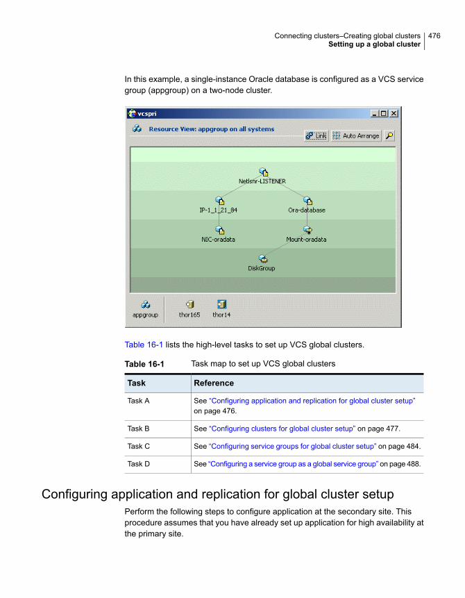
In this example, a single-instance Oracle database is configured as a VCS servicegroup (appgroup) on a two-node cluster.
Table 16-1 lists the high-level tasks to set up VCS global clusters.
Table 16-1 Task map to set up VCS global clusters
ReferenceTask
See “Configuring application and replication for global cluster setup”on page 476.
Task A
See “Configuring clusters for global cluster setup” on page 477.Task B
See “Configuring service groups for global cluster setup” on page 484.Task C
See “Configuring a service group as a global service group” on page 488.Task D
Configuring application and replication for global cluster setupPerform the following steps to configure application at the secondary site. Thisprocedure assumes that you have already set up application for high availability atthe primary site.
476Connecting clusters–Creating global clustersSetting up a global cluster

To configure application and replication
1 At the secondary site, install and configure the application that you want tomake highly available.
See the corresponding application documentation for instructions.
2 At each site, set up data replication using a replication technology that VCSsupports:
■ Volume ReplicatorSee the Veritas InfoScale 7.2 Installation Guide and the Veritas InfoScale7.2 Replication Administrator's Guide for instructions.
■ A supported third-party replication technologySee the corresponding replication documentation for instructions. See theHigh Availability Agent Pack Getting Started Guide for a list of third-partyreplication technologies that VCS supports.
Configuring clusters for global cluster setupPerform the following steps to configure the clusters for disaster recovery:
■ Configure global cluster components at the primary siteSee “Configuring global cluster components at the primary site” on page 477.
■ Install and configure VCS at the secondary siteSee “Installing and configuring VCS at the secondary site” on page 479.
■ Secure communication between the wide-area connectorsSee “Securing communication between the wide-area connectors” on page 479.
■ Configure remote cluster objectsSee “Configuring remote cluster objects” on page 481.
■ Configure additional heartbeat links (optional)See “Configuring additional heartbeat links (optional)” on page 481.
■ Configure the Steward process (optional)See “Configuring the Steward process (optional)” on page 481.
Configuring global cluster components at the primary sitePerform the following steps to configure global cluster components at the primarysite.
If you have already completed these steps during the VCS cluster configuration atthe primary site, then proceed to the next task to set up a VCS cluster at thesecondary site.
477Connecting clusters–Creating global clustersSetting up a global cluster

See “Installing and configuring VCS at the secondary site” on page 479.
Run the GCO Configuration wizard to create or update the ClusterService group.The wizard verifies your configuration and validates it for a global cluster setup.
See “About installing a VCS license” on page 92.
To configure global cluster components at the primary site
1 Start the GCO Configuration wizard.
# gcoconfig
The wizard discovers the NIC devices on the local system and prompts you toenter the device to be used for the global cluster.
2 Specify the name of the device and press Enter.
3 If you do not have NIC resources in your configuration, the wizard asks youwhether the specified NIC will be the public NIC used by all systems.
Enter y if it is the public NIC; otherwise enter n. If you entered n, the wizardprompts you to enter the names of NICs on all systems.
4 Enter the virtual IP to be used for the global cluster.
You must use either IPv4 or IPv6 address. VCS does not support configuringclusters that use different Internet Protocol versions in a global cluster.
5 If you do not have IP resources in your configuration, the wizard does thefollowing:
■ For IPv4 address:The wizard prompts you for the netmask associated with the virtual IP. Thewizard detects the netmask; you can accept the suggested value or enteranother value.
■ For IPv6 address:The wizard prompts you for the prefix associated with the virtual IP.
6 The wizard prompts for the values for the network hosts. Enter the values.
7 The wizard starts running commands to create or update the ClusterServicegroup. Various messages indicate the status of these commands. After runningthese commands, the wizard brings the ClusterService group online.
8 Verify that the gcoip resource that monitors the virtual IP address for inter-clustercommunication is online.
# hares -state gcoip
478Connecting clusters–Creating global clustersSetting up a global cluster

Installing and configuring VCS at the secondary sitePerform the following steps to set up a VCS cluster at the secondary site.
To install and configure VCS at the secondary site
1 At the secondary site, install and configure VCS cluster.
Note the following points for this task:
■ During VCS configuration, answer the prompts to configure global cluster.This step configures the virtual IP for inter-cluster communication.
See the Cluster Server Configuration and Upgrade Guide for instructions.
2 Verify that the gcoip resource that monitors the virtual IP address for inter-clustercommunication is online.
# hares -state gcoip
Securing communication between the wide-areaconnectorsPerform the following steps to configure secure communication between thewide-area connectors.
To secure communication between the wide-area connectors
1 Verify that security is configured in both the clusters. You can use theinstallvcs -security command to configure security.
For more information, see theCluster Server Configuration and Upgrade Guide.
2 Establish trust between the clusters.
For example in a VCS global cluster environment with two clusters, performthe following steps to establish trust between the clusters:
■ On each node of the first cluster, enter the following command:
# export EAT_DATA_DIR=/var/VRTSvcs/vcsauth/data/WAC;
/opt/VRTSvcs/bin/vcsat setuptrust -b
IP_address_of_any_node_from_the_second_cluster:14149 -s high
The command obtains and displays the security certificate and other detailsof the root broker of the second cluster.If the details are correct, enter y at the command prompt to establish trust.For example:
479Connecting clusters–Creating global clustersSetting up a global cluster

The hash of above credential is
b36a2607bf48296063068e3fc49188596aa079bb
Do you want to trust the above?(y/n) y
■ On each node of the second cluster, enter the following command:
# export EAT_DATA_DIR=/var/VRTSvcs/vcsauth/data/WAC
/opt/VRTSvcs/bin/vcsat setuptrust -b
IP_address_of_any_node_from_the_first_cluster:14149 -s high
The command obtains and displays the security certificate and other detailsof the root broker of the first cluster.If the details are correct, enter y at the command prompt to establish trust.Alternatively, if you have passwordless communication set up on the cluster,you can use the installvcs -securitytrust option to set up trust witha remote cluster.
3 Skip the remaining steps in this procedure if you used the installvcs
-security command after the global cluster was set up.■
■ Complete the remaining steps in this procedure if you had a secure clusterand then used the gcoconfig command.
On each cluster, take the wac resource offline on the node where the wacresource is online. For each cluster, run the following command:
# hares -offline wac -sys node_where_wac_is_online
4 Update the values of the StartProgram and MonitorProcesses attributes of thewac resource:
# haconf -makerw
hares -modify wac StartProgram \
"/opt/VRTSvcs/bin/wacstart -secure"
hares -modify wac MonitorProcesses \
"/opt/VRTSvcs/bin/wac -secure"
haconf -dump -makero
5 On each cluster, bring the wac resource online. For each cluster, run thefollowing command on any node:
# hares -online wac -sys systemname
480Connecting clusters–Creating global clustersSetting up a global cluster

Configuring remote cluster objectsAfter you set up the VCS and replication infrastructure at both sites, you must linkthe two clusters. You must configure remote cluster objects at each site to link thetwo clusters. The Remote Cluster Configuration wizard provides an easy interfaceto link clusters.
To configure remote cluster objects
◆ Start the Remote Cluster Configuration wizard.
From Cluster Explorer, click Edit > Add/Delete Remote Cluster.
You must use the same IP address as the one assigned to the IP resource inthe ClusterService group. Global clusters use this IP address to communicateand exchange ICMP heartbeats between the clusters.
Configuring additional heartbeat links (optional)You can configure additional heartbeat links to exchange ICMP heartbeats betweenthe clusters.
To configure an additional heartbeat between the clusters (optional)
1 On Cluster Explorer’s Edit menu, click Configure Heartbeats.
2 In the Heartbeat configuration dialog box, enter the name of the heartbeat andselect the check box next to the name of the cluster.
3 Click the icon in the Configure column to open the Heartbeat Settings dialogbox.
4 Specify the value of the Arguments attribute and various timeout and intervalfields. Click + to add an argument value; click - to delete it.
If you specify IP addresses in the Arguments attribute, make sure the IPaddresses have DNS entries.
5 Click OK.
6 Click OK in the Heartbeat configuration dialog box.
Now, you can monitor the state of both clusters from the Java Console.
Configuring the Steward process (optional)In case of a two-cluster global cluster setup, you can configure a Steward to preventpotential split-brain conditions, provided the proper network infrastructure exists.
See “About the Steward process: Split-brain in two-cluster global clusters”on page 470.
481Connecting clusters–Creating global clustersSetting up a global cluster
To configure the Steward process for clusters not running in secure mode
1 Identify a system that will host the Steward process.
2 Make sure that both clusters can connect to the system through a pingcommand.
3 Copy the file steward from a node in the cluster to the Steward system. Thefile resides at the following path:
/opt/VRTSvcs/bin/
4 In both clusters, set the Stewards attribute to the IP address of the systemrunning the Steward process.
For example:
cluster cluster1938 (
UserNames = { admin = gNOgNInKOjOOmWOiNL }
ClusterAddress = "10.182.147.19"
Administrators = { admin }
CredRenewFrequency = 0
CounterInterval = 5
Stewards = {"10.212.100.165"}
}
5 On the system designated to host the Steward, start the Steward process:
# steward -start
To configure the Steward process for clusters running in secure mode
1 Verify that the prerequisites for securing Steward communication are met.
See “ Prerequisites for clusters running in secure mode” on page 474.
To verify that the wac process runs in secure mode, do the following:
■ Check the value of the wac resource attributes:
# hares -value wac StartProgram
The value must be “/opt/VRTSvcs/bin/wacstart –secure.”
# hares -value wac MonitorProcesses
The value must be “/opt/VRTSvcs/bin/wac –secure.”
■ List the wac process:
# ps -ef | grep wac
482Connecting clusters–Creating global clustersSetting up a global cluster

The wac process must run as “/opt/VRTSvcs/bin/wac –secure.”
2 Identify a system that will host the Steward process.
3 Make sure that both clusters can connect to the system through a pingcommand.
4 Perform this step only if VCS is not already installed on the Steward system.If VCS is already installed, skip to step 5.
■ If the cluster UUID is not configured, configure it by using/opt/VRTSvcs/bin/uuidconfig.pl.
■ On the system that is designated to run the Steward process, run theinstallvcs -securityonenode command.The installer prompts for a confirmation if VCS is not configured or if VCSis not running on all nodes of the cluster. Enter y when the installer promptswhether you want to continue configuring security.For more information about the -securityonenode option, see the ClusterServer Configuration and Upgrade Guide.
5 Generate credentials for the Steward using/opt/VRTSvcs/bin/steward_secure.pl or perform the following steps:
# unset EAT_DATA_DIR
# unset EAT_HOME_DIR
# /opt/VRTSvcs/bin/vcsauth/vcsauthserver/bin/vssat createpd -d
VCS_SERVICES -t ab
# /opt/VRTSvcs/bin/vcsauth/vcsauthserver/bin/vssat addprpl -t ab
-d VCS_SERVICES -p STEWARD -s password
# mkdir -p /var/VRTSvcs/vcsauth/data/STEWARD
# export EAT_DATA_DIR=/var/VRTSvcs/vcsauth/data/STEWARD
# /opt/VRTSvcs/bin/vcsat setuptrust -s high -b localhost:14149
6 Set up trust on all nodes of the GCO clusters:
# export EAT_DATA_DIR=/var/VRTSvcs/vcsauth/data/WAC
# vcsat setuptrust -b <IP_of_Steward>:14149 -s high
483Connecting clusters–Creating global clustersSetting up a global cluster

7 Set up trust on the Steward:
# export EAT_DATA_DIR=/var/VRTSvcs/vcsauth/data/STEWARD
# vcsat setuptrust -b <VIP_of_remote_cluster1>:14149 -s high
# vcsat setuptrust -b <VIP_of_remote_cluster2>:14149 -s high
8 In both the clusters, set the Stewards attribute to the IP address of the systemrunning the Steward process.
For example:
cluster cluster1938 (
UserNames = { admin = gNOgNInKOjOOmWOiNL }
ClusterAddress = "10.182.147.19"
Administrators = { admin }
CredRenewFrequency = 0
CounterInterval = 5
Stewards = {"10.212.100.165"}
}
9 On the system designated to run the Steward, start the Steward process:
# /opt/VRTSvcs/bin/steward -start -secure
To stop the Steward process
◆ To stop the Steward process that is not configured in secure mode, open anew command window and run the following command:
# steward -stop
To stop the Steward process running in secure mode, open a new commandwindow and run the following command:
# steward -stop -secure
Configuring service groups for global cluster setupPerform the following steps to configure the service groups for disaster recovery.
To configure service groups
1 At the secondary site, set up the application for high availability.
Configure VCS service groups for the application. Create a configuration thatis similar to the one in the first cluster.
484Connecting clusters–Creating global clustersSetting up a global cluster

■ You can do this by either using Cluster Manager (Java Console) to copyand paste resources from the primary cluster, or by copying the configurationfrom the main.cf file in the primary cluster to the secondary cluster.
■ Make appropriate changes to the configuration. For example, you mustmodify the SystemList attribute to reflect the systems in the secondarycluster.
■ Make sure that the name of the service group (appgroup) is identical inboth clusters.
2 To assign remote administration privileges to users for remote clusteroperations, configure users with the same name and privileges on both clusters.
See “User privileges for cross-cluster operations” on page 82.
3 If your setup uses BIND DNS, add a resource of type DNS to the applicationservice group at each site.
Refer to theCluster Server Bundled Agent’s Reference Guide for more details.
4 At each site, perform the following depending on the replication technologyyou have set up:
■ Volume ReplicatorConfigure VCS to manage and monitor Replicated Volume Groups (RVGs).See “Configuring VCS service group for VVR-based replication” on page 485.
■ A supported third-party replication technologyInstall and configure the corresponding VCS agent for replication.See the Installation and Configuration Guide for the corresponding VCSreplication agent for instructions.
Configuring VCS service group for VVR-based replicationPerform the following steps to configure VCS to monitor Volume Replicator (VVR).Then, set an online local hard group dependency from application service group(appgroup) to replication service group (appgroup_rep) to ensure that the servicegroups fail over and switch together.
To create the RVG resources in VCS
1 Create a new service group, say appgroup_rep.
2 Copy the DiskGroup resource from the appgroup to the new group.
3 Configure new resources of type IP and NIC in the appgroup_rep service group.The IP resource monitors the virtual IP that VVR uses for replication.
4 Configure a new resource of type RVG in the new (appgroup_rep) servicegroup.
485Connecting clusters–Creating global clustersSetting up a global cluster

5 Configure the RVG resource.
See the Veritas InfoScale™ Replication Administrator’s Guide for moreinformation about the resource.
Note that the RVG resource starts, stops, and monitors the RVG in its currentstate and does not promote or demote VVR when you want to change thedirection of replication. That task is managed by the RVGPrimary agent.
6 Set dependencies as per the following information:
■ RVG resource depends on the IP resource.
■ RVG resource depends on the DiskGroup resource.
■ IP resource depends on the NIC resource.
The service group now looks like:
7 Delete the DiskGroup resource from the appgroup service group.
486Connecting clusters–Creating global clustersSetting up a global cluster
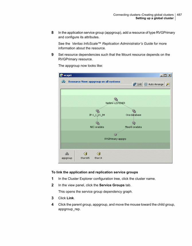
8 In the application service group (appgroup), add a resource of type RVGPrimaryand configure its attributes.
See the Veritas InfoScale™ Replication Administrator’s Guide for moreinformation about the resource.
9 Set resource dependencies such that the Mount resource depends on theRVGPrimary resource.
The appgroup now looks like:
To link the application and replication service groups
1 In the Cluster Explorer configuration tree, click the cluster name.
2 In the view panel, click the Service Groups tab.
This opens the service group dependency graph.
3 Click Link.
4 Click the parent group, appgroup, and move the mouse toward the child group,appgroup_rep.
487Connecting clusters–Creating global clustersSetting up a global cluster

5 Click the child group appgroup_rep.
6 In the Link Service Groups dialog box, click the online local relationship andthe hard dependency type and click OK.
Configuring a service group as a global service groupRun the Global Group Configuration wizard to configure the application servicegroup (appgroup) as a global group.
To create the global service group
1 In the service group tree of Cluster Explorer, right-click the application servicegroup (appgroup).
2 Select Configure As Global from the menu.
3 Enter the details of the service group to modify (appgroup).
4 From the Available Clusters box, click the clusters on which the group cancome online. The local cluster is not listed as it is implicitly defined to be partof the ClusterList. Click the right arrow to move the cluster name to theClusterList box.
5 Select the policy for cluster failover:
■ Manual prevents a group from automatically failing over to another cluster.
■ Auto enables a group to automatically fail over to another cluster if it isunable to fail over within the cluster, or if the entire cluster faults.
■ Connected enables a group to automatically fail over to another cluster ifit is unable to fail over within the cluster.
6 Click Next.
7 Enter or review the connection details for each cluster.
Click the Configure icon to review the remote cluster information for eachcluster.
8 Enter the IP address of the remote cluster, the IP address of a cluster system,or the host name of a cluster system.
9 Enter the user name and the password for the remote cluster and click OK.
10 Click Next.
11 Click Finish.
12 Save the configuration.
The appgroup service group is now a global group and can be failed overbetween clusters.
488Connecting clusters–Creating global clustersSetting up a global cluster

About cluster faultsIn the global cluster setup, consider a case where the primary cluster suffers afailure. The Oracle service group cannot fail over in the local cluster and must failover globally, to a node in another cluster.
In this situation, VCS sends an alert indicating that the cluster is down.
An administrator can bring the group online in the remote cluster.
The RVGPrimary agent ensures that Volume Replicator volumes are made writableand the DNS agent ensures that name services are resolved to the remote site.The application can be started at the remote site.
About the type of failureIf a disaster disables all processing power in your primary data center, heartbeatsfrom the failover site to the primary data center fail. VCS sends an alert signallingcluster failure. If you choose to take action on this failure, VCS prompts you todeclare the type of failure.
You can choose one of the following options to declare the failure:
■ Disaster, implying permanent loss of the primary data center
■ Outage, implying the primary may return to its current form in some time
■ Disconnect, implying a split-brain condition; both clusters are up, but the linkbetween them is broken
■ Replica, implying that data on the takeover target has been made consistentfrom a backup source and that the RVGPrimary can initiate a takeover whenthe service group is brought online. This option applies to Volume Replicatorenvironments only.
You can select the groups to be failed over to the local cluster, in which case VCSbrings the selected groups online on a node based on the group’s FailOverPolicyattribute. It also marks the groups as being OFFLINE in the other cluster. If you donot select any service groups to fail over, VCS takes no action except implicitlymarking the service groups as offline in the failed cluster.
Switching the service group back to the primaryYou can switch the service group back to the primary after resolving the fault at theprimary site. Before switching the application to the primary site, you mustresynchronize any changed data from the active Secondary site since the failover.This can be done manually through Volume Replicator or by running a VCS actionfrom the RVGPrimary resource.
489Connecting clusters–Creating global clustersAbout cluster faults

To switch the service groupwhen the primary site has failed and the secondarydid a takeover
1 In the Service Groups tab of the configuration tree, right-click the resource.
2 Click Actions.
3 Specify the details of the action:
■ From the Action list, choose fbsync.
■ Click the system on which to execute the action.
■ Click OK.
This begins a fast-failback of the replicated data set. You can monitor the valueof the ResourceInfo attribute for the RVG resource to determine when theresynchronization has completed.
4 Once the resynchronization completes, switch the service group to the primarycluster.
■ In the Service Groups tab of the Cluster Explorer configuration tree,right-click the service group.
■ Click Switch To, and click Remote switch.
■ In the Switch global group dialog box, click the cluster to switch the group.Click the specific system, or click Any System, and click OK.
About setting up a disaster recovery fire drillThe disaster recovery fire drill procedure tests the fault-readiness of a configurationby mimicking a failover from the primary site to the secondary site. This procedureis done without stopping the application at the primary site and disrupting useraccess, interrupting the flow of replicated data, or causing the secondary site toneed resynchronization.
The initial steps to create a fire drill service group on the secondary site that closelyfollows the configuration of the original application service group and contains apoint-in-time copy of the production data in the Replicated Volume Group (RVG).Bringing the fire drill service group online on the secondary site demonstrates theability of the application service group to fail over and come online at the secondarysite, should the need arise. Fire drill service groups do not interact with outsideclients or with other instances of resources, so they can safely come online evenwhen the application service group is online.
You must conduct a fire drill only at the secondary site; do not bring the fire drillservice group online on the node hosting the original application.
490Connecting clusters–Creating global clustersAbout setting up a disaster recovery fire drill
You can override the FireDrill attribute and make fire drill resource-specific.
Before you perform a fire drill in a disaster recovery setup that uses VolumeReplicator, perform the following steps:
■ Configure the fire drill service group.See “About creating and configuring the fire drill service group manually”on page 491.See “About configuring the fire drill service group using the Fire Drill Setupwizard” on page 494.If you configure the fire drill service group manually using the command line orthe Cluster Manager (Java Console), set an offline local dependency betweenthe fire drill service group and the application service group to make sure a firedrill does not block an application failover in case a disaster strikes the primarysite. If you use the Fire Drill Setup (fdsetup) wizard, the wizard creates thisdependency.
■ Set the value of the ReuseMntPt attribute to 1 for all Mount resources.
■ After the fire drill service group is taken offline, reset the value of the ReuseMntPtattribute to 0 for all Mount resources.
VCS also supports HA fire drills to verify a resource can fail over to another nodein the cluster.
See “About testing resource failover by using HA fire drills” on page 211.
Note: You can conduct fire drills only on regular VxVM volumes; volume sets (vset)are not supported.
VCS provides hardware replication agents for array-based solutions, such as HitachiTruecopy, EMC SRDF, and so on . If you are using hardware replication agents tomonitor the replicated data clusters, refer to the VCS replication agent documentationfor details on setting up and configuring fire drill.
About creating and configuring the fire drill service group manuallyYou can create the fire drill service group using the command line or ClusterManager (Java Console.) The fire drill service group uses the duplicated copy ofthe application data.
Creating and configuring the fire drill service group involves the following tasks:
■ See “Creating the fire drill service group” on page 492.
■ See “Linking the fire drill and replication service groups” on page 493.
■ See “Adding resources to the fire drill service group” on page 493.
491Connecting clusters–Creating global clustersAbout setting up a disaster recovery fire drill

■ See “Configuring the fire drill service group” on page 493.
■ See “Enabling the FireDrill attribute” on page 494.
Creating the fire drill service groupThis section describes how to use the Cluster Manager (Java Console) to createthe fire drill service group and change the failover attribute to false so that the firedrill service group does not failover to another node during a test.
To create the fire drill service group
1 Open the Veritas Cluster Manager (Java Console). (Start > All Programs >Veritas > Veritas Cluster Manager - Java Console)
On Windows 2012 operating systems, use the Apps menu.
2 Log on to the cluster and click OK.
3 Click the Service Group tab in the left pane and click the Resources tab inthe right pane.
4 Right-click the cluster in the left pane and click Add Service Group.
5 In the Add Service Group dialog box, provide information about the newservice group.
■ In Service Group name, enter a name for the fire drill service group
■ Select systems from the Available Systems box and click the arrows to addthem to the Systems for Service Group box.
■ Click OK.
To disable the AutoFailOver attribute
1 Click the Service Group tab in the left pane and select the fire drill servicegroup.
2 Click the Properties tab in the right pane.
3 Click the Show all attributes button.
4 Double-click the AutoFailOver attribute.
5 In the Edit Attribute dialog box, clear the AutoFailOver check box.
6 Click OK to close the Edit Attribute dialog box.
7 Click the Save and Close Configuration icon in the tool bar.
492Connecting clusters–Creating global clustersAbout setting up a disaster recovery fire drill

Linking the fire drill and replication service groupsCreate an online local firm dependency link between the fire drill service group andthe replication service group.
To link the service groups
1 In Cluster Explorer, click the System tab in the left pane and click theServiceGroups tab in the right pane.
2 Click Link.
3 Click the fire drill service group, drag the link and click the replication servicegroup.
4 Define the dependency. Choose the online local and firm options and clickOK.
Adding resources to the fire drill service groupAdd resources to the new fire drill service group to recreate key aspects of theapplication service group.
To add resources to the service group
1 In Cluster Explorer, click the Service Group tab in the left pane, click theapplication service group and click the Resources tab in the right pane.
2 Right-click the resource at the top of the tree, select Copy and click Self andChild Nodes.
3 In the left pane, click the fire drill service group.
4 Right-click the right pane, and click Paste.
5 In the Name Clashes dialog box, specify a way for the resource names to bemodified, for example, insert an FD_ prefix. Click Apply.
6 Click OK.
Configuring the fire drill service groupAfter copying resources to the fire drill service group, edit the resources so theywill work properly with the duplicated data. The attributes must be modified to reflectthe configuration at the remote site. Bringing the service group online withoutmodifying resource attributes is likely to result in a cluster fault and interruption inservice.
493Connecting clusters–Creating global clustersAbout setting up a disaster recovery fire drill

To configure the service group
1 In Cluster Explorer, click the Service Group tab in the left pane, click the firedrill service group in the left pane and click the Resources tab in the rightpane.
2 Right-click the RVGPrimary resource and click Delete.
3 Right-click the resource to be edited and click View > Properties View. If aresource to be edited does not appear in the pane, click Show All Attributes.
4 Edit attributes to reflect the configuration at the remote site. For example,change the MountV resources so that they point to the volumes used in thefire drill service group. Similarly, reconfigure the DNS and IP resources.
Enabling the FireDrill attributeYou must edit certain resource types so they are FireDrill-enabled. Making aresource type FireDrill-enabled changes the way that VCS checks for concurrencyviolations. Typically, when FireDrill is not enabled, resources can not come onlineon more than one node in a cluster at a time. This behavior prevents multiple nodesfrom using a single resource or from answering client requests. Fire drill servicegroups do not interact with outside clients or with other instances of resources, sothey can safely come online even when the application service group is online.
Typically, you would enable the FireDrill attribute for the resource type that are usedto configure the agent.
To enable the FireDrill attribute
1 In Cluster Explorer, click the Types tab in the left pane, right-click the type tobe edited, and click View > Properties View.
2 Click Show All Attributes.
3 Double click FireDrill.
4 In the Edit Attribute dialog box, enable FireDrill as required, and click OK.
Repeat the process of enabling the FireDrill attribute for all required resourcetypes.
About configuring the fire drill service group using the Fire Drill Setupwizard
Use the Fire Drill Setup Wizard to set up the fire drill configuration.
The wizard performs the following specific tasks:
■ Creates a Cache object to store changed blocks during the fire drill, whichminimizes disk space and disk spindles required to perform the fire drill.
494Connecting clusters–Creating global clustersAbout setting up a disaster recovery fire drill

■ Configures a VCS service group that resembles the real application group.
The wizard works only with application groups that contain one disk group. Thewizard sets up the first RVG in an application. If the application has more than oneRVG, you must create space-optimized snapshots and configure VCS manually,using the first RVG as reference.
You can schedule the fire drill for the service group using the fdsched script.
See “Scheduling a fire drill” on page 497.
Running the fire drill setup wizardTo run the wizard
1 Start the RVG Secondary Fire Drill wizard on the Volume Replicator secondarysite, where the application service group is offline and the replication group isonline as a secondary:
# /opt/VRTSvcs/bin/fdsetup
2 Read the information on the Welcome screen and press the Enter key.
3 The wizard identifies the global service groups. Enter the name of the servicegroup for the fire drill.
4 Review the list of volumes in disk group that could be used for aspace-optimized snapshot. Enter the volumes to be selected for the snapshot.Typically, all volumes used by the application, whether replicated or not, shouldbe prepared, otherwise a snapshot might not succeed.
Press the Enter key when prompted.
495Connecting clusters–Creating global clustersAbout setting up a disaster recovery fire drill
5 Enter the cache size to store writes when the snapshot exists. The size of thecache must be large enough to store the expected number of changed blocksduring the fire drill. However, the cache is configured to grow automatically ifit fills up. Enter disks on which to create the cache.
Press the Enter key when prompted.
6 The wizard starts running commands to create the fire drill setup.
Press the Enter key when prompted.
The wizard creates the application group with its associated resources. It alsocreates a fire drill group with resources for the application (Oracle, for example),the Mount, and the RVGSnapshot types.
The application resources in both service groups define the same application,the same database in this example. The wizard sets the FireDrill attribute forthe application resource to 1 to prevent the agent from reporting a concurrencyviolation when the actual application instance and the fire drill service groupare online at the same time.
About configuring local attributes in the fire drill servicegroupThe fire drill setup wizard does not recognize localized attribute values for resources.If the application service group has resources with local (per-system) attributevalues, you must manually set these attributes after running the wizard.
Verifying a successful fire drillIf you configured the fire drill service group manually using the command line orthe Cluster Manager (Java Console), make sure that you set an offline localdependency between the fire drill service group and the application service group.This dependency ensures that a fire drill does not block an application failover incase a disaster strikes the primary site.
Bring the fire drill service group online on a node that does not have the applicationrunning. Verify that the fire drill service group comes online. This action validatesthat your disaster recovery solution is configured correctly and the production servicegroup will fail over to the secondary site in the event of an actual failure (disaster)at the primary site.
If the fire drill service group does not come online, review the VCS engine log totroubleshoot the issues so that corrective action can be taken as necessary in theproduction service group.
You can also view the fire drill log, located at /tmp/fd-servicegroup.pid
496Connecting clusters–Creating global clustersAbout setting up a disaster recovery fire drill

Remember to take the fire drill offline once its functioning has been validated. Failingto take the fire drill offline could cause failures in your environment. For example,if the application service group were to fail over to the node hosting the fire drillservice group, there would be resource conflicts, resulting in both service groupsfaulting.
Scheduling a fire drillYou can schedule the fire drill for the service group using the fdsched script. Thefdsched script is designed to run only on the lowest numbered node that is currentlyrunning in the cluster. The scheduler runs the command hagrp - online
firedrill_group -any at periodic intervals.
To schedule a fire drill
1 Add the file /opt/VRTSvcs/bin/fdsched to your crontab.
2 To make fire drills highly available, add the fdsched file to each node in thecluster.
Multi-tiered application support using theRemoteGroup agent in a global environment
Figure 16-5 represents a two-site, two-tier environment. The application cluster,which is globally clustered between L.A. and Denver, has cluster dependencies upand down the tiers. Cluster 1 (C1), depends on the remote service group for cluster3 (C3). At the same time, cluster 2 (C2) also depends on the remote service groupfor cluster 4 (C4).
497Connecting clusters–Creating global clustersMulti-tiered application support using the RemoteGroup agent in a global environment

Figure 16-5 A VCS two-tiered globally clustered application and database
Stockton Denver
Cluster 3 (C3) Cluster 4 (C4)
Databasetier
Global local service group (LSG)with a RemoteGroup resource (RGR)
Global clusterCluster 1 (C1) Cluster 2 (C2)
Applicationtier
Global remote servicegroup (RSG)
Global cluster
Just as a two-tier, two-site environment is possible, you can also tie a three-tierenvironment together.
Figure 16-6 represents a two-site, three-tier environment. The application cluster,which is globally clustered between L.A. and Denver, has cluster dependencies upand down the tiers. Cluster 1 (C1), depends on the RemoteGroup resource on theDB tier for cluster 3 (C3), and then on the remote service group for cluster 5 (C5).The stack for C2, C4, and C6 functions the same.
498Connecting clusters–Creating global clustersMulti-tiered application support using the RemoteGroup agent in a global environment

Figure 16-6 A three-tiered globally clustered application, database, andstorage
Stockton Denver
Global clusterCluster 1 (C1) Cluster 2 (C2)
Webapplication
tier
Cluster 3 (C3) Cluster 4 (C4)
Applicationtier
Global middle service group (GMG)with a RemoteGroup resource (RGR)
Global cluster
Cluster 5 (C5) Cluster 6 (C6)
Databasetier
Global cluster
Global local service group (LSG)with a RemoteGroup resource (RGR)
Global remote servicegroup (RSG)
Test scenario for a multi-tiered environmentIn the following scenario, eight systems reside in four clusters. Each tier containsa global cluster. The global local service group in the top tier depends on the globalremote service group in the bottom tier.
The following main.cf files show this multi-tiered environment. The FileOnOffresource is used to test the dependencies between layers. Note that some attributeshave been edited for clarity, and that these clusters are not running in secure mode.
Figure 16-7 shows the scenario for testing.
499Connecting clusters–Creating global clustersTest scenario for a multi-tiered environment

Figure 16-7 A VCS two-tiered globally clustered scenario
Site A Site B
C3= 10.182.6.152 C4= 10.182.6.154
Global clusterC1= 10.182.10.145 C2= 10.182.10.146
Global cluster
sysA sysB sysC sysD
sysW sysX sysY sysZ
About the main.cf file for cluster 1The contents of the main.cf file for cluster 1 (C1) in the top tier, containing the sysAand sysB nodes.
include "types.cf"
cluster C1 (
ClusterAddress = "10.182.10.145"
)
remotecluster C2 (
ClusterAddress = "10.182.10.146"
)
heartbeat Icmp (
ClusterList = { C2 }
AYATimeout = 30
Arguments @C2 = { "10.182.10.146" }
500Connecting clusters–Creating global clustersTest scenario for a multi-tiered environment

)
system sysA (
)
system sysB (
)
group LSG (
SystemList = { sysA = 0, sysB = 1 }
ClusterList = { C2 = 0, C1 = 1 }
AutoStartList = { sysA, sysB }
ClusterFailOverPolicy = Auto
)
FileOnOff filec1 (
PathName = "/tmp/c1"
)
RemoteGroup RGR (
IpAddress = "10.182.6.152"
// The above IPAddress is the highly available address of C3—
// the same address that the wac uses
Username = root
Password = xxxyyy
GroupName = RSG
VCSSysName = ANY
ControlMode = OnOff
)
About the main.cf file for cluster 2The contents of the main.cf file for cluster 2 (C2) in the top tier, containing the sysCand sysD nodes.
include "types.cf"
cluster C2 (
ClusterAddress = "10.182.10.146"
)
remotecluster C1 (
ClusterAddress = "10.182.10.145"
501Connecting clusters–Creating global clustersTest scenario for a multi-tiered environment

)
heartbeat Icmp (
ClusterList = { C1 }
AYATimeout = 30
Arguments @C1 = { "10.182.10.145" }
)
system sysC (
)
system sysD (
)
group LSG (
SystemList = { sysC = 0, sysD = 1 }
ClusterList = { C2 = 0, C1 = 1 }
Authority = 1
AutoStartList = { sysC, sysD }
ClusterFailOverPolicy = Auto
)
FileOnOff filec2 (
PathName = filec2
)
RemoteGroup RGR (
IpAddress = "10.182.6.154"
// The above IPAddress is the highly available address of C4—
// the same address that the wac uses
Username = root
Password = vvvyyy
GroupName = RSG
VCSSysName = ANY
ControlMode = OnOff
)
About the main.cf file for cluster 3The contents of the main.cf file for cluster 3 (C3) in the bottom tier, containing thesysW and sysX nodes.
502Connecting clusters–Creating global clustersTest scenario for a multi-tiered environment

include "types.cf"
cluster C3 (
ClusterAddress = "10.182.6.152"
)
remotecluster C4 (
ClusterAddress = "10.182.6.154"
)
heartbeat Icmp (
ClusterList = { C4 }
AYATimeout = 30
Arguments @C4 = { "10.182.6.154" }
)
system sysW (
)
system sysX (
)
group RSG (
SystemList = { sysW = 0, sysX = 1 }
ClusterList = { C3 = 1, C4 = 0 }
AutoStartList = { sysW, sysX }
ClusterFailOverPolicy = Auto
)
FileOnOff filec3 (
PathName = "/tmp/filec3"
)
About the main.cf file for cluster 4The contents of the main.cf file for cluster 4 (C4) in the bottom tier, containing thesysY and sysZ nodes.
include "types.cf"
cluster C4 (
ClusterAddress = "10.182.6.154"
)
503Connecting clusters–Creating global clustersTest scenario for a multi-tiered environment

remotecluster C3 (
ClusterAddress = "10.182.6.152"
)
heartbeat Icmp (
ClusterList = { C3 }
AYATimeout = 30
Arguments @C3 = { "10.182.6.152" }
)
system sysY (
)
system sysZ (
)
group RSG (
SystemList = { sysY = 0, sysZ = 1 }
ClusterList = { C3 = 1, C4 = 0 }
Authority = 1
AutoStartList = { sysY, sysZ }
ClusterFailOverPolicy = Auto
)
FileOnOff filec4 (
PathName = "/tmp/filec4"
)
504Connecting clusters–Creating global clustersTest scenario for a multi-tiered environment

Administering globalclusters from thecommand line
This chapter includes the following topics:
■ About administering global clusters from the command line
■ About global querying in a global cluster setup
■ Administering global service groups in a global cluster setup
■ Administering resources in a global cluster setup
■ Administering clusters in global cluster setup
■ Administering heartbeats in a global cluster setup
About administering global clusters from thecommand line
For remote cluster operations, you must configure a VCS user with the same nameand privileges in each cluster.
See “User privileges for cross-cluster operations” on page 82.
Review the following procedures to administer global clusters from thecommand-line.
See “About global querying in a global cluster setup” on page 506.
See “Administering global service groups in a global cluster setup” on page 513.
17Chapter

See “Administering resources in a global cluster setup” on page 515.
See “Administering clusters in global cluster setup” on page 515.
See “Administering heartbeats in a global cluster setup” on page 518.
About global querying in a global cluster setupVCS enables you to query global cluster objects, including service groups, resources,systems, resource types, agents, and clusters. You may enter query commandsfrom any system in the cluster. Commands to display information on the globalcluster configuration or system states can be executed by all users; you do notneed root privileges. Only global service groups may be queried.
See “Querying global cluster service groups” on page 506.
See “Querying resources across clusters” on page 507.
See “Querying systems” on page 509.
See “Querying clusters” on page 509.
See “Querying status” on page 511.
See “Querying heartbeats” on page 511.
Querying global cluster service groupsThis topic describes how to perform a query on global cluster service groups:
To display service group attribute values across clusters
◆ Use the following command to display service group attribute values acrossclusters:
hagrp -value service_group attribute [system]
[-clus cluster | -localclus]
The option -clus displays the attribute value on the cluster designated by thevariable cluster; the option -localclus specifies the local cluster.
If the attribute has local scope, you must specify the system name, exceptwhen querying the attribute on the system from which you run the command.
506Administering global clusters from the command lineAbout global querying in a global cluster setup

To display the state of a service group across clusters
◆ Use the following command to display the state of a service group acrossclusters:
hagrp -state [service_groups -sys systems]
[-clus cluster | -localclus]
The option -clus displays the state of all service groups on a cluster designatedby the variable cluster; the option -localclus specifies the local cluster.
To display service group information across clusters
◆ Use the following command to display service group information across clusters:
hagrp -display [service_groups] [-attribute attributes]
[-sys systems] [-clus cluster | -localclus]
The option -clus applies to global groups only. If the group is local, the clustername must be the local cluster name, otherwise no information is displayed.
To display service groups in a cluster
◆ Use the following command to display service groups in a cluster:
hagrp -list [conditionals] [-clus cluster | -localclus]
The option -clus lists all service groups on the cluster designated by thevariable cluster; the option -localclus specifies the local cluster.
To display usage for the service group command
◆ Use the following command to display usage for the service group command:
hagrp [-help [-modify|-link|-list]]
Querying resources across clustersThis topic describes how to perform queries on resources:
507Administering global clusters from the command lineAbout global querying in a global cluster setup

To display resource attribute values across clusters
◆ Use the following command to display resource attribute values across clusters:
hares -value resource attribute [system]
[-clus cluster | -localclus]
The option -clus displays the attribute value on the cluster designated by thevariable cluster; the option -localclus specifies the local cluster.
If the attribute has local scope, you must specify the system name, exceptwhen querying the attribute on the system from which you run the command.
To display the state of a resource across clusters
◆ Use the following command to display the state of a resource across clusters:
hares -state [resource -sys system]
[-clus cluster | -localclus]
The option -clus displays the state of all resources on the specified cluster;the option -localclus specifies the local cluster. Specifying a system displaysresource state on a particular system.
To display resource information across clusters
◆ Use the following command to display resource information across clusters:
hares -display [resources] [-attribute attributes]
[-group service_groups] [-type types] [-sys systems]
[-clus cluster | -localclus]
The option -clus lists all service groups on the cluster designated by thevariable cluster; the option -localclus specifies the local cluster.
To display a list of resources across clusters
◆ Use the following command to display a list of resources across clusters:
hares -list [conditionals] [-clus cluster | -localclus]
The option -clus lists all resources that meet the specified conditions in globalservice groups on a cluster as designated by the variable cluster.
To display usage for the resource command
◆ Use the following command to display usage for the resource command:
hares -help [-modify | -list]
508Administering global clusters from the command lineAbout global querying in a global cluster setup
Querying systemsThis topic describes how to perform queries on systems:
To display system attribute values across clusters
◆ Use the following command to display system attribute values across clusters:
hasys -value system attribute [-clus cluster | -localclus]
The option -clus displays the values of a system attribute in the cluster asdesignated by the variable cluster; the option -localclus specifies the localcluster.
To display the state of a system across clusters
◆ Use the following command to display the state of a system across clusters:
hasys -state [system] [-clus cluster | -localclus]
Displays the current state of the specified system. The option -clus displaysthe state in a cluster designated by the variable cluster; the option -localclus
specifies the local cluster. If you do not specify a system, the command displaysthe states of all systems.
For information about each system across clusters
◆ Use the following command to display information about each system acrossclusters:
hasys -display [systems] [-attribute attributes] [-clus cluster |
-localclus]
The option -clus displays the attribute values on systems (if specified) in acluster designated by the variable cluster; the option -localclus specifies thelocal cluster.
For a list of systems across clusters
◆ Use the following command to display a list of systems across clusters:
hasys -list [conditionals] [-clus cluster | -localclus]
Displays a list of systems whose values match the given conditional statements.The option -clus displays the systems in a cluster designated by the variablecluster; the option -localclus specifies the local cluster.
Querying clustersThis topic describes how to perform queries on clusters:
509Administering global clusters from the command lineAbout global querying in a global cluster setup
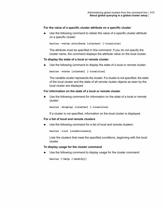
For the value of a specific cluster attribute on a specific cluster
◆ Use the following command to obtain the value of a specific cluster attributeon a specific cluster:
haclus -value attribute [cluster] [-localclus]
The attribute must be specified in this command. If you do not specify thecluster name, the command displays the attribute value on the local cluster.
To display the state of a local or remote cluster
◆ Use the following command to display the state of a local or remote cluster:
haclus -state [cluster] [-localclus]
The variable cluster represents the cluster. If a cluster is not specified, the stateof the local cluster and the state of all remote cluster objects as seen by thelocal cluster are displayed.
For information on the state of a local or remote cluster
◆ Use the following command for information on the state of a local or remotecluster:
haclus -display [cluster] [-localclus]
If a cluster is not specified, information on the local cluster is displayed.
For a list of local and remote clusters
◆ Use the following command for a list of local and remote clusters:
haclus -list [conditionals]
Lists the clusters that meet the specified conditions, beginning with the localcluster.
To display usage for the cluster command
◆ Use the following command to display usage for the cluster command:
haclus [-help [-modify]]
510Administering global clusters from the command lineAbout global querying in a global cluster setup

To display the status of a faulted cluster
◆ Use the following command to display the status of a faulted cluster:
haclus -status cluster
Displays the status on the specified faulted cluster. If no cluster is specified,the command displays the status on all faulted clusters. It lists the servicegroups that were not in the OFFLINE or the FAULTED state before the faultoccurred. It also suggests corrective action for the listed clusters and servicegroups.
Querying statusThis topic describes how to perform queries on status of remote and local clusters:
For the status of local and remote clusters
◆ Use the following command to obtain the status of local and remote clusters:
hastatus
Querying heartbeatsThe hahb command is used to manage WAN heartbeats that emanate from thelocal cluster. Administrators can monitor the "health of the remote cluster viaheartbeat commands and mechanisms such as Internet, satellites, or storagereplication technologies. Heartbeat commands are applicable only on the clusterfrom which they are issued.
Note: You must have Cluster Administrator privileges to add, delete, and modifyheartbeats.
The following commands are issued from the command line.
For a list of heartbeats configured on the local cluster
◆ Use the following command for a list of heartbeats configured on the localcluster:
hahb -list [conditionals]
The variable conditionals represents the conditions that must be met for theheartbeat to be listed.
511Administering global clusters from the command lineAbout global querying in a global cluster setup

To display information on heartbeats configured in the local cluster
◆ Use the following command to display information on heartbeats configured inthe local cluster:
hahb -display [heartbeat ...]
If heartbeat is not specified, information regarding all heartbeats configured onthe local cluster is displayed.
To display the state of the heartbeats in remote clusters
◆ Use the following command to display the state of heartbeats in remote clusters:
hahb -state [heartbeat] [-clus cluster]
For example, to get the state of heartbeat Icmp from the local cluster to theremote cluster phoenix:
hahb -state Icmp -clus phoenix
To display an attribute value of a configured heartbeat
◆ Use the following command to display an attribute value of a configuredheartbeat:
hahb -value heartbeat attribute [-clus cluster]
The -value option provides the value of a single attribute for a specificheartbeat. The cluster name must be specified for cluster-specific attributevalues, but not for global.
For example, to display the value of the ClusterList attribute for heartbeat Icmp:
hahb -value Icmp ClusterList
Note that ClusterList is a global attribute.
To display usage for the command hahb
◆ Use the following command to display usage for the command hahb:
hahb [-help [-modify]]
If the -modify option is specified, the usage for the hahb -modify option isdisplayed.
512Administering global clusters from the command lineAbout global querying in a global cluster setup

Administering global service groups in a globalcluster setup
Operations for the VCS global clusters option are enabled or restricted dependingon the permissions with which you log on. The privileges associated with each userrole are enforced for cross-cluster, service group operations.
This topic includes commands to administer global service groups.
See the hagrp (1M) manual page for more information.
To administer global service groups in a global cluster setup
◆ Depending on the administrative task you want to perform on global servicegroups, run the hagrp command as follows:
hagrp -online -forceTo bring a servicegroup onlineacross clusters forthe first time
hagrp -online service_group -sys system [-cluscluster | -localclus]
The option -clus brings the service group online on the systemdesignated in the cluster. If a system is not specified, the servicegroup is brought online on any node within the cluster. The option-localclus brings the service group online in the local cluster.
To bring a servicegroup onlineacross clusters
hagrp -online [-force] service_group -any [-cluscluster | -localclus]
The option -any specifies that HAD brings a failover group onlineon the optimal system, based on the requirements of service groupworkload management and existing group dependencies. Ifbringing a parallel group online, HAD brings the group online oneach system designated in the SystemList attribute.
To bring a servicegroup online onany node
hagrp -resources service_group [-cluscluster_name | -localclus]
The option -clus displays information for the cluster designatedby the variable cluster_name; the option -localclus specifiesthe local cluster.
To display theresources for aservice group
513Administering global clusters from the command lineAdministering global service groups in a global cluster setup
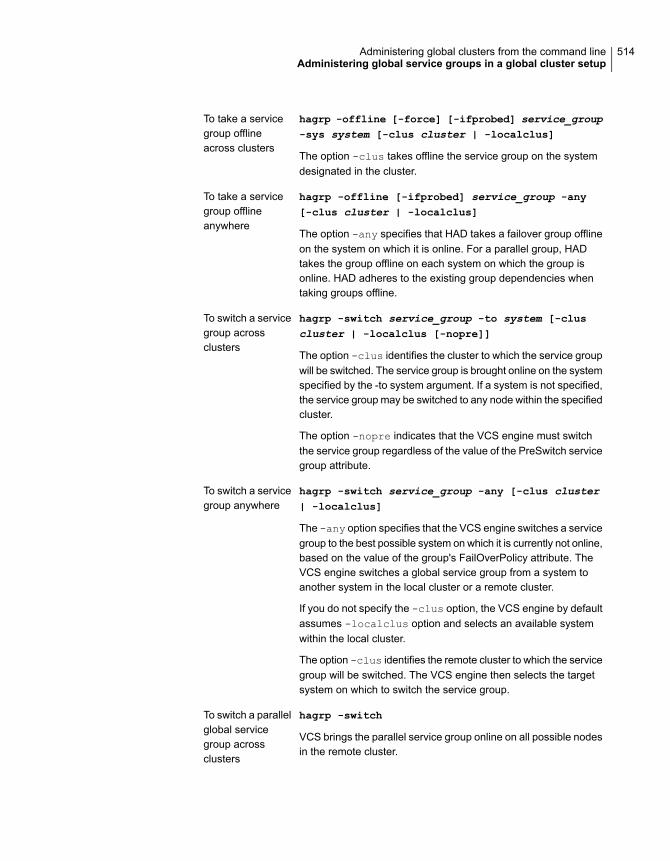
hagrp -offline [-force] [-ifprobed] service_group-sys system [-clus cluster | -localclus]
The option -clus takes offline the service group on the systemdesignated in the cluster.
To take a servicegroup offlineacross clusters
hagrp -offline [-ifprobed] service_group -any[-clus cluster | -localclus]
The option -any specifies that HAD takes a failover group offlineon the system on which it is online. For a parallel group, HADtakes the group offline on each system on which the group isonline. HAD adheres to the existing group dependencies whentaking groups offline.
To take a servicegroup offlineanywhere
hagrp -switch service_group -to system [-cluscluster | -localclus [-nopre]]
The option -clus identifies the cluster to which the service groupwill be switched. The service group is brought online on the systemspecified by the -to system argument. If a system is not specified,the service group may be switched to any node within the specifiedcluster.
The option -nopre indicates that the VCS engine must switchthe service group regardless of the value of the PreSwitch servicegroup attribute.
To switch a servicegroup acrossclusters
hagrp -switch service_group -any [-clus cluster| -localclus]
The -any option specifies that the VCS engine switches a servicegroup to the best possible system on which it is currently not online,based on the value of the group's FailOverPolicy attribute. TheVCS engine switches a global service group from a system toanother system in the local cluster or a remote cluster.
If you do not specify the -clus option, the VCS engine by defaultassumes -localclus option and selects an available systemwithin the local cluster.
The option -clus identifies the remote cluster to which the servicegroup will be switched. The VCS engine then selects the targetsystem on which to switch the service group.
To switch a servicegroup anywhere
hagrp -switch
VCS brings the parallel service group online on all possible nodesin the remote cluster.
To switch a parallelglobal servicegroup acrossclusters
514Administering global clusters from the command lineAdministering global service groups in a global cluster setup

Administering resources in a global cluster setupThis topic describes how to administer resources.
See the hares (1M) manual page for more information.
To administer resources in a global cluster setup
◆ Depending on the administrative task you want to perform for resources, runthe hares command as follows:
hares -action resource token [-actionargs arg1...] [-sys system] [-clus cluster | -localclus]
The option -clus implies resources on the cluster. If thedesignated system is not part of the local cluster, an error isdisplayed. If the -sys option is not used, it implies resources onthe local node.
To take action on aresource acrossclusters
hares -refreshinfo resource [-sys system] [-cluscluster | -localclus]
Causes the Info function to update the value of the ResourceInforesource level attribute for the specified resource if the resourceis online. If no system or remote cluster is specified, the Infofunction runs on local system(s) where the resource is online.
To invoke the Infofunction acrossclusters
hares [-help [-modify |-list]]To display usagefor the resourcecommand
Administering clusters in global cluster setupThe topic includes commands that are used to administer clusters in a global clustersetup.
See the haclus (1M) manual page for more information.
To administer clusters in global cluster setup
◆ Depending on the administrative task you want to perform on the clusters, runthe haclus command as follows:
The variable cluster in the following commands represents the cluster.
haclus -add cluster ip
This command does not apply to the local cluster.
To add a remotecluster object
515Administering global clusters from the command lineAdministering resources in a global cluster setup

haclus -delete clusterTo delete a remotecluster object
haclus -modify attribute value [-cluscluster]...
To modify an attributeof a local or remotecluster object
haclus -declaredisconnet/outage/disaster/replica -cluscluster [-failover]
To declare the state ofa cluster after adisaster
See “Managing cluster alerts in a global cluster setup”on page 516.
To manage clusteralerts
See “Changing the cluster name in a global cluster setup”on page 517.
To change the clustername
Managing cluster alerts in a global cluster setupThis topic includes commands to manage cluster alerts.
See the haalert (1M) manual page for more information.
To manage cluster alerts
◆ Run the haalert command to manage cluster alerts.
Generates a simulated "cluster fault" alert that is sentto the VCS engine and GUI.
haalert -testfd
For each alert, the command displays the followinginformation:
■ alert ID■ time when alert occurred■ cluster on which alert occurred■ object name for which alert occurred■ (cluster name, group name, and so on).■ informative message about alert
haalert -display
For each alert, the command displays the followinginformation:
■ time when alert occurred■ alert ID
haalert -list
516Administering global clusters from the command lineAdministering clusters in global cluster setup

Deletes a specific alert. You must enter a text messagewithin quotes describing the reason for deleting thealert. The comment is written to the engine log as wellas sent to any connected GUI clients.
haalert -deletealert_id -notes"description"
Displays the usage texthaalert -help
Changing the cluster name in a global cluster setupThis topic describes how to change the ClusterName attribute in a global clusterconfiguration. The instructions describe how to rename VCSPriCluster toVCSPriCluster2 in a two-cluster configuration, comprising clusters VCSPriClusterand VCSSecCluster configured with the global group AppGroup.
Before changing the cluster name, make sure the cluster is not part of anyClusterList, in the wide-area Heartbeat agent and in global service groups.
To change the name of a cluster
1 Run the following commands from cluster VCSPriCluster:
hagrp -offline ClusterService -any
hagrp -modify AppGroup ClusterList -delete VCSPriCluster
haclus -modify ClusterName VCSPriCluster2
hagrp -modify AppGroup ClusterList -add VCSPriCluster2 0
2 Run the following commands from cluster VCSSecCluster:
hagrp -offline ClusterService -any
hagrp -modify appgrp ClusterList -delete VCSPriCluster
hahb -modify Icmp ClusterList -delete VCSPriCluster
haclus -delete VCSPriCluster
haclus -add VCSPriCluster2 your_ip_address
hahb -modify Icmp ClusterList -add VCSPriCluster2
hahb -modify Icmp Arguments your_ip_address -clus VCSPriCluster2
hagrp -modify AppGroup ClusterList -add VCSPriCluster2 0
hagrp -online ClusterService -any
3 Run the following command from the cluster renamed to VCSPriCluster2:
hagrp -online ClusterService -any
517Administering global clusters from the command lineAdministering clusters in global cluster setup
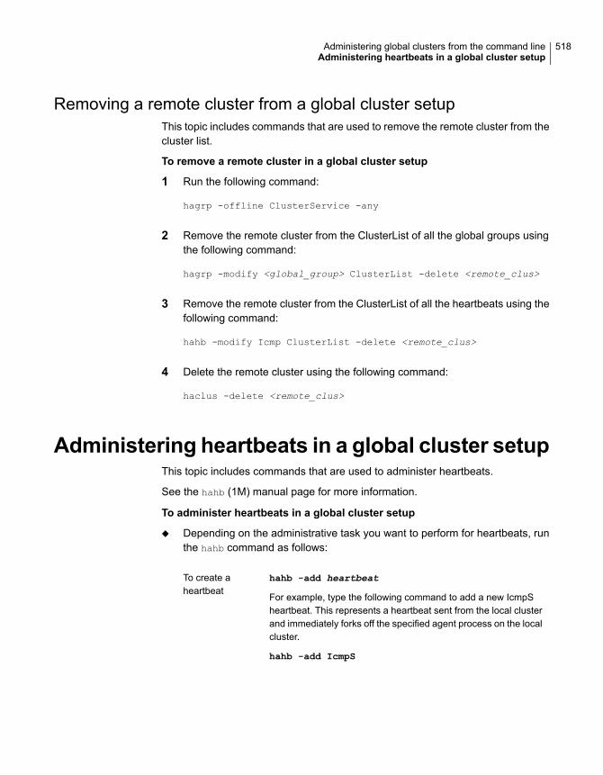
Removing a remote cluster from a global cluster setupThis topic includes commands that are used to remove the remote cluster from thecluster list.
To remove a remote cluster in a global cluster setup
1 Run the following command:
hagrp -offline ClusterService -any
2 Remove the remote cluster from the ClusterList of all the global groups usingthe following command:
hagrp -modify <global_group> ClusterList -delete <remote_clus>
3 Remove the remote cluster from the ClusterList of all the heartbeats using thefollowing command:
hahb -modify Icmp ClusterList -delete <remote_clus>
4 Delete the remote cluster using the following command:
haclus -delete <remote_clus>
Administering heartbeats in a global cluster setupThis topic includes commands that are used to administer heartbeats.
See the hahb (1M) manual page for more information.
To administer heartbeats in a global cluster setup
◆ Depending on the administrative task you want to perform for heartbeats, runthe hahb command as follows:
hahb -add heartbeat
For example, type the following command to add a new IcmpSheartbeat. This represents a heartbeat sent from the local clusterand immediately forks off the specified agent process on the localcluster.
hahb -add IcmpS
To create aheartbeat
518Administering global clusters from the command lineAdministering heartbeats in a global cluster setup

hahb -modify heartbeat attribute value ... [-cluscluster]
If the attribute is local, that is, it has a separate value for eachremote cluster in the ClusterList attribute, the option -cluscluster must be specified. Use -delete -keys to clear thevalue of any list attributes.
For example, type the following command to modify the ClusterListattribute and specify targets "phoenix and "houston for the newlycreated heartbeat:
hahb -modify Icmp ClusterList phoenix houston
To modify the Arguments attribute for target phoenix:
hahb -modify Icmp Arguments phoenix.example.com-clus phoenix
To modify aheartbeat
hahb -delete heartbeatTo delete aheartbeat
hahb -local heartbeat attribute
For example, type the following command to change the scope ofthe attribute AYAInterval from global to cluster-specific:
hahb -local Icmp AYAInterval
To change thescope of anattribute tocluster-specific
hahb -global heartbeat attribute value ... | key... | key value ...
For example, type the following command to change the scope ofthe attribute AYAInterval from cluster-specific to cluster-generic:
hahb -global Icmp AYAInterval 60
To change thescope of anattribute to global
519Administering global clusters from the command lineAdministering heartbeats in a global cluster setup

Setting up replicated dataclusters
This chapter includes the following topics:
■ About replicated data clusters
■ How VCS replicated data clusters work
■ About setting up a replicated data cluster configuration
■ About migrating a service group
■ About setting up a fire drill
About replicated data clustersThe Replicated Data Cluster (RDC) configuration provides both local high availabilityand disaster recovery functionality in a single VCS cluster.
You can set up RDC in a VCS environment using Volume Replicator (VVR).
A Replicated Data Cluster (RDC) uses data replication to assure data access tonodes. An RDC exists within a single VCS cluster. In an RDC configuration, if anapplication or a system fails, the application is failed over to another system withinthe current primary site. If the entire primary site fails, the application is migratedto a system in the remote secondary site (which then becomes the new primary).
For VVR replication to occur, the disk groups containing the Replicated VolumeGroup (RVG) must be imported at the primary and secondary sites. The replicationservice group must be online at both sites simultaneously, and must be configuredas a hybrid VCS service group.
18Chapter

The application service group is configured as a failover service group. Theapplication service group must be configured with an online local hard dependencyon the replication service group.
Note: VVR supports multiple replication secondary targets for any given primary.However, RDC for VCS supports only one replication secondary for a primary.
An RDC configuration is appropriate in situations where dual dedicated LLT linksare available between the primary site and the disaster recovery secondary sitebut lacks shared storage or SAN interconnect between the primary and secondarydata centers. In an RDC, data replication technology is employed to provide nodeaccess to data in a remote site.
Note: You must use dual dedicated LLT links between the replicated nodes.
How VCS replicated data clusters workTo understand how a replicated data cluster configuration works, let us take theexample of an application configured in a VCS replicated data cluster. Theconfiguration has two system zones:
■ Primary zone (zone 0) comprising nodes located at the primary site and attachedto the primary storage
■ Secondary zone (zone 1) comprising nodes located at the secondary site andattached to the secondary storage
The application is installed and configured on all nodes in the cluster. Applicationdata is located on shared disks within each RDC site and is replicated across RDCsite to ensure data concurrency. The application service group is online on a systemin the current primary zone and is configured to fail over in the cluster.
Figure 18-1 depicts an application configured on a VCS replicated data cluster.
521Setting up replicated data clustersHow VCS replicated data clusters work

Figure 18-1 A VCS replicated data cluster configuration
PublicNetwork
SeparateStorage
SeparateStorage
Client Client Client Client
ReplicatedData
ClientsRedirected
ApplicationFailover
Zone 0 Zone 1
Private Network
ServiceGroup
ServiceGroup
In the event of a system or application failure, VCS attempts to fail over theapplication service group to another system within the same RDC site. However,in the event that VCS fails to find a failover target node within the primary RDC site,VCS switches the service group to a node in the current secondary RDC site (zone1).
About setting up a replicated data clusterconfiguration
This topic describes the steps for planning, configuring, testing, and using the VCSRDC configuration to provide a robust and easy-to-manage disaster recoveryprotection for your applications. It describes an example of converting a singleinstance Oracle database configured for local high availability in a VCS cluster toa disaster-protected RDC infrastructure. The solution uses Volume Replicator toreplicate changed data.
About typical replicated data cluster configurationFigure 18-2 depicts a dependency chart of a typical RDC configuration.
522Setting up replicated data clustersAbout setting up a replicated data cluster configuration

Figure 18-2 Dependency chart of a typical RDC configuration
RVGPrimary
DNS
IP
Application Group
NIC
IP
NIC
RVG
DiskGroup
Replication Group
Application
Mount
online local hard dependency
In this example, a single-instance application is configured as a VCS service group(DiskGroup) on a four-node cluster, with two nodes in the primary RDC systemzone and two in the secondary RDC system zone. In the event of a failure on theprimary node, VCS fails over the application to the second node in the primaryzone.
The process involves the following steps:
■ Setting Up Replication
■ Configuring the Service Groups
■ Configuring the Service Group Dependencies
About setting up replicationVeritas Volume Replicator (VVR) technology is a license-enabled feature of VeritasVolume Manager (VxVM), so you can convert VxVM-managed volumes intoreplicated volumes managed using VVR. In this example, the process involvesgrouping the Oracle data volumes into a Replicated Volume Group (RVG), andcreating the VVR Secondary on hosts in another VCS cluster, located in your DRsite.
When setting up VVR, it is a best practice to use the same DiskGroup and RVGname on both sites. If the volume names are the same on both zones, the Mountresources will mount the same block devices, and the same Oracle instance willstart on the secondary in case of a failover.
523Setting up replicated data clustersAbout setting up a replicated data cluster configuration

Configuring the service groupsThis topic describes how to configure service groups.
To configure the replication group
1 Create a hybrid service group (oragrp_rep) for replication.
See “Types of service groups” on page 33.
2 Copy the DiskGroup resource from the application to the new group. Configurethe resource to point to the disk group that contains the RVG.
3 Configure new resources of type IP and NIC.
4 Configure a new resource of type RVG in the service group.
5 Set resource dependencies as per the following information:
■ RVG resource depends on the IP resource
■ RVG resource depends on the DiskGroup resourceIP resource depends on the NIC resource
6 Set the SystemZones attribute of the child group, oragrp_rep, such that allnodes in the primary RDC zone are in system zone 0 and all nodes in thesecondary RDC zone are in system zone 1.
To configure the application service group
1 In the original Oracle service group (oragroup), delete the DiskGroup resource.
2 Add an RVGPrimary resource and configure its attributes.
Set the value of the RvgResourceName attribute to the name of the RVG typeresource that will be promoted and demoted by the RVGPrimary agent.
Set the AutoTakeover and AutoResync attributes from their defaults as desired.
3 Set resource dependencies such that all Mount resources depend on theRVGPrimary resource. If there are a lot of Mount resources, you can set theTypeDependencies attribute for the group to denote that the Mount resourcetype depends on the RVGPRimary resource type.
524Setting up replicated data clustersAbout setting up a replicated data cluster configuration
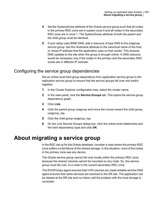
4 Set the SystemZones attribute of the Oracle service group such that all nodesin the primary RDC zone are in system zone 0 and all nodes in the secondaryRDC zone are in zone 1. The SystemZones attribute of both the parent andthe child group must be identical.
5 If your setup uses BIND DNS, add a resource of type DNS to the oragroupservice group. Set the Hostname attribute to the canonical name of the hostor virtual IP address that the application uses on that cluster. This ensuresDNS updates to the site when the group is brought online. A DNS resourcewould be necessary only if the nodes in the primary and the secondary RDCzones are in different IP subnets.
Configuring the service group dependenciesSet an online local hard group dependency from application service group to thereplication service group to ensure that the service groups fail over and switchtogether.
1 In the Cluster Explorer configuration tree, select the cluster name.
2 In the view panel, click the Service Groups tab. This opens the service groupdependency graph.
3 Click Link.
4 Click the parent group oragroup and move the mouse toward the child group,oragroup_rep.
5 Click the child group oragroup_rep.
6 On the Link Service Groups dialog box, click the online local relationship andthe hard dependency type and click OK.
About migrating a service groupIn the RDC set up for the Oracle database, consider a case where the primary RDCzone suffers a total failure of the shared storage. In this situation, none of the nodesin the primary zone see any device.
The Oracle service group cannot fail over locally within the primary RDC zone,because the shared volumes cannot be mounted on any node. So, the servicegroup must fail over, to a node in the current secondary RDC zone.
The RVGPrimary agent ensures that VVR volumes are made writable and the DNSagent ensures that name services are resolved to the DR site. The application canbe started at the DR site and run there until the problem with the local storage iscorrected.
525Setting up replicated data clustersAbout migrating a service group

If the storage problem is corrected, you can switch the application to the primarysite using VCS.
Switching the service groupBefore switching the application back to the original primary RDC zone, you mustresynchronize any changed data from the active DR site since the failover. Thiscan be done manually through VVR or by running a VCS action from theRVGPrimary resource.
To switch the service group
1 In the Service Groups tab of the configuration tree, right-click the resource.
2 Click Actions.
3 Specify the details of the action as follows:
■ From the Action list, choose fbsync.
■ Click the system on which to execute the action.
■ Click OK.
This begins a fast-failback of the replicated data set. You can monitor the valueof the ResourceInfo attribute for the RVG resource to determine when theresynchronization has completed.
4 Once the resynchronization completes, switch the service group to the primarycluster. In the Service Groups tab of the of the Cluster Explorer configurationtree, right-click the service group.
5 Click Switch To and select the system in the primary RDC zone to switch toand click OK.
About setting up a fire drillYou can use fire drills to test the configuration's fault readiness by mimicking afailover without stopping the application in the primary data center.
See “About setting up a disaster recovery fire drill” on page 490.
526Setting up replicated data clustersAbout setting up a fire drill

Setting up campusclusters
This chapter includes the following topics:
■ About campus cluster configuration
■ VCS campus cluster requirements
■ Typical VCS campus cluster setup
■ How VCS campus clusters work
■ About setting up a campus cluster configuration
■ Fire drill in campus clusters
■ About the DiskGroupSnap agent
■ About running a fire drill in a campus cluster
About campus cluster configurationThe campus cluster configuration provides local high availability and disasterrecovery functionality in a single VCS cluster. This configuration uses data mirroringto duplicate data at different sites. There is no Host or Array base replicationinvolved.
VCS supports campus clusters that employ disk groups mirrored with Veritas VolumeManager.
19Chapter
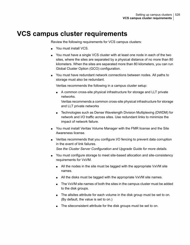
VCS campus cluster requirementsReview the following requirements for VCS campus clusters:
■ You must install VCS.
■ You must have a single VCS cluster with at least one node in each of the twosites, where the sites are separated by a physical distance of no more than 80kilometers. When the sites are separated more than 80 kilometers, you can runGlobal Cluster Option (GCO) configuration.
■ You must have redundant network connections between nodes. All paths tostorage must also be redundant.
Veritas recommends the following in a campus cluster setup:
■ A common cross-site physical infrastructure for storage and LLT privatenetworks.Veritas recommends a common cross-site physical infrastructure for storageand LLT private networks
■ Technologies such as Dense Wavelength Division Multiplexing (DWDM) fornetwork and I/O traffic across sites. Use redundant links to minimize theimpact of network failure.
■ You must install Veritas Volume Manager with the FMR license and the SiteAwareness license.
■ Veritas recommends that you configure I/O fencing to prevent data corruptionin the event of link failures.See the Cluster Server Configuration and Upgrade Guide for more details.
■ You must configure storage to meet site-based allocation and site-consistencyrequirements for VxVM.
■ All the nodes in the site must be tagged with the appropriate VxVM sitenames.
■ All the disks must be tagged with the appropriate VxVM site names.
■ The VxVM site names of both the sites in the campus cluster must be addedto the disk groups.
■ The allsites attribute for each volume in the disk group must be set to on.(By default, the value is set to on.)
■ The siteconsistent attribute for the disk groups must be set to on.
528Setting up campus clustersVCS campus cluster requirements

Typical VCS campus cluster setupFigure 19-1 depicts a typical VCS campus cluster setup.
Figure 19-1 Typical VCS campus cluster setup
Site A (primary) Site B (secondary)
node1 node2 node3 node4
Public network
Private network
Switch Switch
Disk array Disk array
Site C
VxVM mirrored volume
Disk array
Campus cluster
Switch
Coordination point
VCS campus cluster typically has the following characteristics:
■ Single VCS cluster spans multiple sites.In the sample figure, VCS is configured on four nodes: node 1 and node 2 arelocated at site A and node 3 and node 4 at site B.
■ I/O fencing is configured with one coordinator disk from each site of the campuscluster and another coordinator disk from a third site.Figure 19-1 illustrates a typical setup with disk-based I/O fencing. You can alsoconfigure server-based I/O fencing.
529Setting up campus clustersTypical VCS campus cluster setup

See “About I/O fencing in campus clusters” on page 534.
■ The shared data is located on mirrored volumes on a disk group configuredusing Veritas Volume Manager.
■ The volumes that are required for the application have mirrors on both the sites.
■ All nodes in the cluster are tagged with the VxVM site name. All disks that belongto a site are tagged with the corresponding VxVM site name.
■ The disk group is configured in VCS as a resource of type DiskGroup and ismounted using the Mount resource type.
How VCS campus clusters workThis topic describes how VCS works with VxVM to provide high availability in acampus cluster environment.
In a campus cluster setup, VxVM automatically mirrors volumes across sites. Toenhance read performance, VxVM reads from the plexes at the local site wherethe application is running. VxVM writes to plexes at both the sites.
In the event of a storage failure at a site, VxVM detaches all the disks at the failedsite from the disk group to maintain data consistency. When the failed storagecomes back online, VxVM automatically reattaches the site to the disk group andrecovers the plexes.
See the Storage Foundation Cluster File System High Availability Administrator'sGuide for more information.
When service group or system faults occur, VCS fails over service groups basedon the values you set for the cluster attribute SiteAware and the service groupattribute AutoFailOver.
See “Service group attributes” on page 680.
See “Cluster attributes” on page 722.
For campus cluster setup, you must define sites and add systems to the sites thatyou defined. A system can belong to only one site. Sit e definitions are uniformacross VCS, You can define sites Veritas InfoScale Operations Manager, andVxVM. You can define site dependencies to restrict connected applications to failover within the same site.
You can define sites by using:
■ Veritas InfoScale Operations ManagerFor more information on configuring sites, see the latest version of the VeritasInfoScale Operations Manager User guide.
530Setting up campus clustersHow VCS campus clusters work

Depending on the value of the AutoFailOver attribute, VCS failover behavior is asfollows:
VCS does not fail over the service group.0
VCS fails over the service group to another suitable node.
By default, the AutoFailOver attribute value is set to 1.
1
VCS fails over the service group if another suitable node exists in thesame site. Otherwise, VCS waits for administrator intervention to initiatethe service group failover to a suitable node in the other site.
This configuration requires the HA/DR license enabled.
Veritas recommends that you set the value of AutoFailOver attribute to2.
2
Sample definition for these service group attributes in the VCS main.cf is as follows:
cluster VCS_CLUS (
PreferredFencingPolicy = Site
SiteAware = 1
)
site MTV (
SystemList = { sys1, sys2 }
)
site SFO (
Preference = 2
SystemList = { sys3, sys4 }
)
The sample configuration for hybrid_group with AutoFailover = 1 and failover_groupwith AutoFailover = 2 is as following:
hybrid_group (
Parallel = 2
SystemList = { sys1 = 0, sys2 = 1, sys3 = 2, sys4 = 3 }
)
failover_group (
AutoFailover = 2
SystemList = { sys1 = 0, sys2 = 1, sys3 = 2, sys4 = 3 }
)
Table 19-1 lists the possible failure scenarios and how VCS campus cluster recoversfrom these failures.
531Setting up campus clustersHow VCS campus clusters work
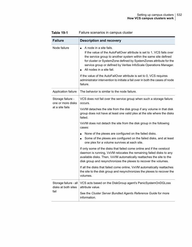
Table 19-1 Failure scenarios in campus cluster
Description and recoveryFailure
■ A node in a site fails.If the value of the AutoFailOver attribute is set to 1, VCS fails overthe service group to another system within the same site definedfor cluster or SystemZone defined by SystemZones attribute for theservice group or defined by Veritas InfoScale Operations Manager.
■ All nodes in a site fail.
If the value of the AutoFailOver attribute is set to 0, VCS requiresadministrator intervention to initiate a fail over in both the cases of nodefailure.
Node failure
The behavior is similar to the node failure.Application failure
VCS does not fail over the service group when such a storage failureoccurs.
VxVM detaches the site from the disk group if any volume in that diskgroup does not have at least one valid plex at the site where the disksfailed.
VxVM does not detach the site from the disk group in the followingcases:
■ None of the plexes are configured on the failed disks.■ Some of the plexes are configured on the failed disks, and at least
one plex for a volume survives at each site.
If only some of the disks that failed come online and if the vxrelocddaemon is running, VxVM relocates the remaining failed disks to anyavailable disks. Then, VxVM automatically reattaches the site to thedisk group and resynchronizes the plexes to recover the volumes.
If all the disks that failed come online, VxVM automatically reattachesthe site to the disk group and resynchronizes the plexes to recover thevolumes.
Storage failure -one or more disksat a site fails
VCS acts based on the DiskGroup agent's PanicSystemOnDGLossattribute value.
See the Cluster Server Bundled Agents Reference Guide for moreinformation.
Storage failure - alldisks at both sitesfail
532Setting up campus clustersHow VCS campus clusters work

Table 19-1 Failure scenarios in campus cluster (continued)
Description and recoveryFailure
All nodes and storage at a site fail.
Depending on the value of the AutoFailOver attribute, VCS fails overthe service group as follows:
■ If the value is set to 1, VCS fails over the service group to a system.■ If the value is set to 2, VCS requires administrator intervention to
initiate the service group failover to a system in the other site.
Because the storage at the failed site is inaccessible, VCS imports thedisk group in the application service group with all devices at the failedsite marked as NODEVICE.
When the storage at the failed site comes online, VxVM automaticallyreattaches the site to the disk group and resynchronizes the plexes torecover the volumes.
Site failure
Nodes at each site lose connectivity to the nodes at the other site
The failure of all private interconnects between the nodes can result insplit brain scenario and cause data corruption.
Review the details on other possible causes of split brain and how I/Ofencing protects shared data from corruption.
See “About data protection” on page 243.
Veritas recommends that you configure I/O fencing to prevent datacorruption in campus clusters.
When the cluster attribute PreferredFencingPolicy is set as Site, thefencing driver gives preference to the node with higher site priorityduring the race for coordination points. VCS uses the site-level attributePreference to determine the node weight.
See “About I/O fencing in campus clusters” on page 534.
Network failure(LLT interconnectfailure)
533Setting up campus clustersHow VCS campus clusters work

Table 19-1 Failure scenarios in campus cluster (continued)
Description and recoveryFailure
Nodes at each site lose connectivity to the storage and the nodes atthe other site
Veritas recommends that you configure I/O fencing to prevent split brainand serial split brain conditions.
■ If I/O fencing is configured:The site that do not win the race triggers a system panic.See “About I/O fencing in campus clusters” on page 534.When you restore the network connectivity, VxVM detects thestorage at the failed site, reattaches the site to the disk group, andresynchronizes the plexes to recover the volumes.
■ If I/O fencing is not configured:If the application service group was online at site A during suchfailure, the application service group remains online at the samesite. Because the storage is inaccessible, VxVM detaches the disksat the failed site from the disk group. At site B where the applicationservice group is offline, VCS brings the application service grouponline and imports the disk group with all devices at site A markedas NODEVICE. So, the application service group is online at boththe sites and each site uses the local storage. This causesinconsistent data copies and leads to a site-wide split brain.When you restore the network connectivity between sites, a serialsplit brain may exist.See the Storage Foundation Administrator's Guide for details torecover from a serial split brain condition.
Network failure(LLT and storageinterconnectfailure)
About I/O fencing in campus clustersYou must configure I/O fencing to prevent corruption of shared data in the event ofa network partition.
See “About membership arbitration” on page 223.
See “About data protection” on page 243.
You can use coordinator disks, coordination point server (CP server), or a mix ofboth as coordination points to configure I/O fencing.
In a campus cluster setup, you can configure I/O fencing as follows:
■ Two coordinator disks at one site and one coordinator disk at the other siteIn this case, the site that has two coordinator disks has a higher probability towin the race. The disadvantage with this configuration is that if the site that hastwo coordinator disks encounters a site failure, then the other site also commits
534Setting up campus clustersHow VCS campus clusters work

suicide. With this configuration, I/O fencing cannot distinguish between aninaccessible disk and a failed preempt operation.
■ One coordinator disk in each of the two sites and a third coordinator disk at athird siteThis configuration ensures that fencing works even if one of the sites becomesunavailable. A coordinator disk in a third site allows at least a sub-cluster tocontinue operations in the event of a site failure in a campus cluster. The sitethat can access the coordinator disk in the third site in addition to its localcoordinator disk wins the race. However, if both the sites of the campus clusterare unable to access the disk at the third site, each site gains one vote and thenodes at both the sites commit suicide.
You can also configure a coordination point server (CP server) at the third siteinstead of a third coordinator disk.
See the Cluster Server Installation Guide for more details to configure I/O fencing.
About setting up a campus cluster configurationYou must perform the following tasks to set up a campus cluster:
■ Preparing to set up a campus cluster configuration
■ Configuring I/O fencing to prevent data corruption
■ Configuring VxVM disk groups for campus cluster configuration
■ Configuring VCS service group for campus clusters
Preparing to set up a campus cluster configurationBefore you set up the configuration, review the VCS campus cluster requirements.
See “ VCS campus cluster requirements” on page 528.
To prepare to set up a campus cluster configuration
1 Set up the physical infrastructure.
■ Set up access to the local storage arrays and to remote storage arrays oneach node.
■ Set up private heartbeat network.
535Setting up campus clustersAbout setting up a campus cluster configuration

See “ Typical VCS campus cluster setup” on page 529.
2 Install VCS on each node to form a cluster with at least one node in each ofthe two sites.
See the Cluster Server Configuration and Upgrade Guide for instructions.
3 Install VxVM on each node with the required licenses.
See the Storage Foundation and High Availability Configuration and UpgradeGuide for instructions.
Configuring I/O fencing to prevent data corruptionPerform the following tasks to configure I/O fencing to prevent data corruption inthe event of a communication failure.
See “About I/O fencing in campus clusters” on page 534.
See the Cluster Server Configuration and Upgrade Guide for more details.
To configure I/O fencing to prevent data corruption
1 Set up the storage at a third site.
You can extend the DWDM to the third site to have FC SAN connectivity tothe storage at the third site. You can also use iSCSI targets as the coordinatordisks at the third site.
2 Set up I/O fencing.
Configuring VxVM disk groups for campus cluster configurationFollow the procedure to configure VxVM disk groups for remote mirroring.
See the Storage Foundation Cluster File System High Availability Administrator'sGuide for more information on the VxVM commands.
Note: You can also configure VxVM disk groups for remote mirroring using VeritasInfoScale Operations Manager.
536Setting up campus clustersAbout setting up a campus cluster configuration

To configure VxVM disk groups for campus cluster configuration
1 Set the site name for each host:
# vxdctl set site=sitename
The site name is stored in the /etc/vx/volboot file. Use the following commandto display the site names:
# vxdctl list | grep siteid
2 Set the site name for all the disks in an enclosure:
# vxdisk settag site=sitename encl:enclosure
To tag specific disks, use the following command:
# vxdisk settag site=sitename disk
3 Verify that the disks are registered to a site.
# vxdisk listtag
4 Create a disk group with disks from both the sites.
# vxdg -s init diskgroup siteA_disk1 siteB_disk2
5 Configure site-based allocation on the disk group that you created for eachsite that is registered to the disk group.
# vxdg -g diskgroup addsite sitename
6 Configure site consistency on the disk group.
# vxdg -g diskgroup set siteconsistent=on
7 Create one or more mirrored volumes in the disk group.
# vxassist -g diskgroup make volume size nmirror=1/2
With the Site Awareness license installed on all hosts, the volume that youcreate has the following characteristics by default:
■ The allsites attribute is set to on; the volumes have at least one plex ateach site.
537Setting up campus clustersAbout setting up a campus cluster configuration

■ The volumes are automatically mirrored across sites.
■ The read policy rdpol is set to siteread.
■ The volumes inherit the site consistency value that is set on the disk group.
Configuring VCS service group for campus clustersFollow the procedure to configure the disk groups under VCS control and set upthe VCS attributes to define failover in campus clusters.
To configure VCS service groups for campus clusters
1 Create a VCS service group (app_sg) for the application that runs in the campuscluster.
hagrp -add app_sg
hagrp -modify app_sg SystemList node1 0 node2 1 node3 2 node4 3
2 Set up the system zones or sites. Configure the SystemZones attribute for theservice group. Skip this step when sites are configured through Veritas InfoScaleOperations Manager.
hagrp -modify app_sg SystemZones node1 0 node2 0 node3 1 node4 1
3 Set up the group fail over policy. Set the value of the AutoFailOver attributefor the service group.
hagrp -modify app_sg AutoFailOver 2
4 For the disk group you created for campus clusters, add a DiskGroup resourceto the VCS service group app_sg.
hares -add dg_res1 DiskGroup app_sg
hares -modify dg_res1 DiskGroup diskgroup_name
hares -modify dg_res1 Enabled 1
5 Configure the application and other related resources to the app_sg servicegroup.
6 Bring the service group online.
Fire drill in campus clustersFire drill tests the disaster-readiness of a configuration by mimicking a failoverwithout stopping the application and disrupting user access.
538Setting up campus clustersFire drill in campus clusters

The process involves creating a fire drill service group, which is similar to the originalapplication service group. Bringing the fire drill service group online on the remotenode demonstrates the ability of the application service group to fail over and comeonline at the site, should the need arise.
Fire drill service groups do not interact with outside clients or with other instancesof resources, so they can safely come online even when the application servicegroup is online. Conduct a fire drill only at the remote site; do not bring the fire drillservice group online on the node hosting the original application.
About the DiskGroupSnap agentThe DiskGroupSnap agent verifies the VxVM disk groups and volumes for siteawareness and disaster readiness in a campus cluster environment. To perform afire drill in campus clusters, you must configure a resource of type DiskGroupSnapin the fire drill service group.
Note: To perform fire drill, the application service group must be online at the primarysite.
During fire drill, the DiskGroupSnap agent does the following:
■ For each node in a site, the agent correlates the value of the SystemZonesattribute for the application service group to the VxVM site names for that node.
■ For the disk group in the application service group, the agent verifies that theVxVM site tags are defined for the disk group.
■ For the disk group in the application service group, the agent verifies that thedisks at the secondary site are not tagged with the same VxVM site name asthe disks at the primary site.
■ The agent verifies that all volumes in the disk group have a plex at each site.
See the Cluster Server Bundled Agents Reference Guide for more information onthe agent.
About running a fire drill in a campus clusterThis topic provides information on how to run a fire drill in campus clusters.
Do the following tasks to perform fire drill:
■ Configuring the fire drill service group
■ Running a successful fire drill in a campus cluster
539Setting up campus clustersAbout the DiskGroupSnap agent

Configuring the fire drill service groupThis topic provides information on how to configure the fire drill service group.
To configure the fire drill service group
1 Configure a fire drill service group similar to the application service group withthe following exceptions:
■ The AutoFailOver attribute must be set to 0.
■ Network-related resources must not be configured.
■ The disk group names for the DiskGroup and the Mount resources in thefire drill service group must be appended with "_fd".For example, if the value of the DiskGroup attribute in the application servicegroup is ccdg, then the corresponding value in the fire drill service groupmust be ccdg_fd.If the value of the BlockDevice attribute for the Mount resource in theapplication service group is /dev/vx/dsk/ccdg/ccvol, then the correspondingvalue in the fire drill service group must be /dev/vx/dsk/ccdg_fd/ccvol.
2 Add a resource of type DiskGroupSnap. Define the TargetResName and theFDSiteName attributes for the DiskGroupSnap resource.
See the Cluster Server Bundled Agent Reference Guide for attributedescriptions.
3 Create a dependency such that the DiskGroup resource depends on theDiskGroupSnap resource.
4 Create a group dependency such that the fire drill service group has an offlinelocal dependency on the application service group.
Running a successful fire drill in a campus clusterBring the fire drill service group online on a node within the system zone that doesnot have the application running. Verify that the fire drill service group comes online.This action validates that your solution is configured correctly and the productionservice group will fail over to the remote site in the event of an actual failure (disaster)at the local site.
You must take the fire drill service group offline before you shut down the node orstop VCS locally on the node where the fire drill service group is online or wherethe disk group is online. Otherwise, after the node restarts you must manuallyreattach the fire drill site to the disk group that is imported at the primary site.
540Setting up campus clustersAbout running a fire drill in a campus cluster

Note: For the applications for which you want to perform fire drill, you must set thevalue of the FireDrill attribute for those application resource types to 1. After youcomplete fire drill, reset the value to 0.
To run a successful fire drill
1 Override the FireDrill attribute at the resource level for resources of the fire drillservice group.
2 Set the FireDrill attribute for the application resources to 1. This prevents theagent from reporting a concurrency violation, when the application servicegroup and the fire drill service group are online at the same time.
3 Bring the fire drill service group online.
If the fire drill service group does not come online, review the VCS engine logto troubleshoot the issues so that corrective action can be taken as necessaryin the production service group.
Warning: You must take the fire drill service group offline after you completethe fire drill so that the failover behavior of the application service group is notimpacted. Otherwise, when a disaster strikes at the primary site, the applicationservice group cannot fail over to the secondary site due to resource conflicts.
4 After you complete the fire drill, take the fire drill service group offline.
5 Reset the Firedrill attribute for the resource to 0.
6 Undo or override the Firedrill attribute from the resource level.
541Setting up campus clustersAbout running a fire drill in a campus cluster

Troubleshooting andperformance
■ Chapter 20. VCS performance considerations
■ Chapter 21. Troubleshooting and recovery for VCS
7Section

VCS performanceconsiderations
This chapter includes the following topics:
■ How cluster components affect performance
■ How cluster operations affect performance
■ About scheduling class and priority configuration
■ CPU binding of HAD
■ VCS agent statistics
■ About VCS tunable parameters
How cluster components affect performanceVCS and its agents run on the same systems as the applications. Therefore, VCSattempts to minimize its impact on overall system performance. The maincomponents of clustering that have an impact on performance include the kernel;specifically, GAB and LLT, the VCS engine (HAD), and the VCS agents. For detailson attributes or commands mentioned in the following sections, see the chapter onadministering VCS from the command line and the appendix on VCS attributes.
See “How kernel components (GAB and LLT) affect performance” on page 544.
See “ How the VCS engine (HAD) affects performance” on page 544.
See “ How agents affect performance” on page 545.
See “How the VCS graphical user interfaces affect performance” on page 546.
20Chapter

How kernel components (GAB and LLT) affect performanceTypically, overhead of VCS kernel components is minimal. Kernel componentsprovide heartbeat and atomic information exchange among cluster systems. Bydefault, each system in the cluster sends two small heartbeat packets per secondto other systems in the cluster.
Heartbeat packets are sent over all network links configured in the /etc/llttab
configuration file.
System-to-system communication is load-balanced across all private network links.If a link fails, VCS continues to use all remaining links. Typically, network links areprivate and do not increase traffic on the public network or LAN. You can configurea public network (LAN) link as low-priority, which by default generates a small(approximately 64-byte) unicast packet per second from each system, and whichwill carry data only when all private network links have failed.
How the VCS engine (HAD) affects performanceThe VCS engine, HAD, runs as a daemon process. By default it runs as ahigh-priority process, which ensures it sends heartbeats to kernel components andresponds quickly to failures. HAD runs logging activities in a separate thread toreduce the performance impact on the engine due to logging.
VCS runs in a loop waiting for messages from agents, ha commands, the graphicaluser interfaces, and the other systems. Under normal conditions, the number ofmessages processed by HAD is few. They mainly include heartbeat messages fromagents and update messages from the global counter. VCS may exchange additionalmessages when an event occurs, but typically overhead is nominal even duringevents. Note that this depends on the type of event; for example, a resource faultmay involve taking the group offline on one system and bringing it online on anothersystem. A system fault invokes failing over all online service groups on the faultedsystem.
To continuously monitor VCS status, use the VCS graphical user interfaces or thecommand hastatus. Both methods maintain connection to VCS and register forevents, and are more efficient compared to running commands like hastatus
-summary or hasys in a loop.
The number of clients connected to VCS can affect performance if several eventsoccur simultaneously. For example, if five GUI processes are connected to VCS,VCS sends state updates to all five. Maintaining fewer client connections to VCSreduces this overhead.
544VCS performance considerationsHow cluster components affect performance
How agents affect performanceThe VCS agent processes have the most impact on system performance. Eachagent process has two components: the agent framework and the agent functions.The agent framework provides common functionality, such as communication withthe HAD, multithreading for multiple resources, scheduling threads, and invokingfunctions. Agent functions implement agent-specific functionality. Review theperformance guidelines to follow when configuring agents.
See “Monitoring resource type and agent configuration” on page 545.
Monitoring resource type and agent configurationBy default, VCS monitors each resource every 60 seconds. You can change thisby modifying the MonitorInterval attribute for the resource type. You may considerreducing monitor frequency for non-critical or resources with expensive monitoroperations. Note that reducing monitor frequency also means that VCS may takelonger to detect a resource fault.
By default, VCS also monitors offline resources. This ensures that if someone bringsthe resource online outside of VCS control, VCS detects it and flags a concurrencyviolation for failover groups. To reduce the monitoring frequency of offline resources,modify the OfflineMonitorInterval attribute for the resource type.
The VCS agent framework uses multithreading to allow multiple resource operationsto run in parallel for the same type of resources. For example, a single Mount agenthandles all mount resources. The number of agent threads for most resource typesis 10 by default. To change the default, modify the NumThreads attribute for theresource type. The maximum value of the NumThreads attribute is 30.
Continuing with this example, the Mount agent schedules the monitor function forall mount resources, based on the MonitorInterval or OfflineMonitorInterval attributes.If the number of mount resources is more than NumThreads, the monitor operationfor some mount resources may be required to wait to execute the monitor functionuntil the thread becomes free.
Additional considerations for modifying the NumThreads attribute include:
■ If you have only one or two resources of a given type, you can set NumThreadsto a lower value.
■ If you have many resources of a given type, evaluate the time it takes for themonitor function to execute and the available CPU power for monitoring. Forexample, if you have 50 mount points, you may want to increase NumThreadsto get the ideal performance for the Mount agent without affecting overall systemperformance.
545VCS performance considerationsHow cluster components affect performance

You can also adjust how often VCS monitors various functions by modifying theirassociated attributes. The attributes MonitorTimeout, OnlineTimeOut, andOfflineTimeout indicate the maximum time (in seconds) within which the monitor,online, and offline functions must complete or else be terminated. The default forthe MonitorTimeout attribute is 60 seconds. The defaults for the OnlineTimeout andOfflineTimeout attributes is 300 seconds. For best results, Veritas recommendsmeasuring the time it takes to bring a resource online, take it offline, and monitorbefore modifying the defaults. Issue an online or offline command to measure thetime it takes for each action. To measure how long it takes to monitor a resource,fault the resource and issue a probe, or bring the resource online outside of VCScontrol and issue a probe.
Agents typically run with normal priority. When you develop agents, consider thefollowing:
■ If you write a custom agent, write the monitor function using C or C++. If youwrite a script-based monitor, VCS must invoke a new process each time withthe monitor. This can be costly if you have many resources of that type.
■ If monitoring the resources is proving costly, you can divide it into cursory, orshallow monitoring, and the more extensive deep (or in-depth) monitoring.Whether to use shallow or deep monitoring depends on your configurationrequirements.
As an additional consideration for agents, properly configure the attribute SystemListfor your service group. For example, if you know that a service group can go onlineon SystemA and SystemB only, do not include other systems in the SystemList.This saves additional agent processes and monitoring overhead.
How the VCS graphical user interfaces affect performanceThe VCS graphical user interface, Cluster Manager (Java Console) maintains apersistent connection to HAD, from which it receives regular updates regardingcluster status. For best results, run the GUI on a system outside the cluster to avoidimpact on node performance.
How cluster operations affect performanceReview the following topics that describe how the following operations on systems,resources, and service groups in the cluster affect performance:
See “ VCS performance consideration when booting a clustersystem” on page 547.
A cluster system boots
546VCS performance considerationsHow cluster operations affect performance

See “ VCS performance consideration when a resourcecomes online” on page 548.
A resource comes online
See “ VCS performance consideration when a resource goesoffline” on page 548.
A resource goes offline
See “VCS performance consideration when a service groupcomes online” on page 548.
A service group comes online
See “VCS performance consideration when a service groupgoes offline” on page 549.
A service group goes offline
See “ VCS performance consideration when a resource fails”on page 549.
A resource fails
See “ VCS performance consideration when a system fails”on page 550.
A system fails
See “ VCS performance consideration when a network linkfails” on page 551.
A network link fails
See “ VCS performance consideration when a system panics”on page 551.
A system panics
See “ VCS performance consideration when a service groupswitches over” on page 553.
A service group switches over
See “ VCS performance consideration when a service groupfails over” on page 554.
A service group fails over
VCS performance consideration when booting a cluster systemWhen a cluster system boots, the kernel drivers and VCS process start in a particularorder. If it is the first system in the cluster, VCS reads the cluster configuration filemain.cf and builds an in-memory configuration database. This is the LOCAL_BUILDstate. After building the configuration database, the system transitions into theRUNNING mode. If another system joins the cluster while the first system is in theLOCAL_BUILD state, it must wait until the first system transitions into RUNNINGmode. The time it takes to build the configuration depends on the number of servicegroups in the configuration and their dependencies, and the number of resourcesper group and resource dependencies. VCS creates an object for each system,service group, type, and resource. Typically, the number of systems, service groupsand types are few, so the number of resources and resource dependenciesdetermine how long it takes to build the configuration database and get VCS intoRUNNING mode. If a system joins a cluster in which at least one system is inRUNNING mode, it builds the configuration from the lowest-numbered system inthat mode.
547VCS performance considerationsHow cluster operations affect performance

Note:Bringing service groups online as part of AutoStart occurs after VCS transitionsto RUNNING mode.
VCS performance consideration when a resource comes onlineThe online function of an agent brings the resource online. This function may returnbefore the resource is fully online. The subsequent monitor determines if theresource is online, then reports that information to VCS. The time it takes to bringa resource online equals the time for the resource to go online, plus the time forthe subsequent monitor to execute and report to VCS.
Most resources are online when the online function finishes. The agent schedulesthe monitor immediately after the function finishes, so the first monitor detects theresource as online. However, for some resources, such as a database server,recovery can take longer. In this case, the time it takes to bring a resource onlinedepends on the amount of data to recover. It may take multiple monitor intervalsbefore a database server is reported online. When this occurs, it is important tohave the correct values configured for the OnlineTimeout and OnlineWaitLimitattributes of the database server resource type.
VCS performance consideration when a resource goes offlineSimilar to the online function, the offline function takes the resource offline and mayreturn before the resource is actually offline. Subsequent monitoring confirmswhether the resource is offline. The time it takes to offline a resource equals thetime it takes for the resource to go offline, plus the duration of subsequent monitoringand reporting to VCS that the resource is offline. Most resources are typically offlinewhen the offline function finishes. The agent schedules the monitor immediatelyafter the offline function finishes, so the first monitor detects the resource as offline.
VCS performance consideration when a service group comes onlineThe time it takes to bring a service group online depends on the number of resourcesin the service group, the service group dependency structure, and the time to bringthe group’s resources online. For example, if service group G1 has three resources,R1, R2, and R3 (where R1 depends on R2 and R2 depends on R3), VCS firstonlines R3. When R3 is online, VCS onlines R2. When R2 is online, VCS onlinesR1. The time it takes to online G1 equals the time it takes to bring all resourcesonline. However, if R1 depends on both R2 and R3, but there was no dependencybetween them, the online operation of R2 and R3 is started in parallel. When bothare online, R1 is brought online. The time it takes to online the group is Max (thetime to online R2 and R3), plus the time to online R1. Typically, broader servicegroup trees allow more parallel operations and can be brought online faster. More
548VCS performance considerationsHow cluster operations affect performance
complex service group trees do not allow much parallelism and serializes the grouponline operation.
VCS performance consideration when a service group goes offlineTaking service groups offline works from the top down, as opposed to the onlineoperation, which works from the bottom up. The time it takes to offline a servicegroup depends on the number of resources in the service group and the time tooffline the group’s resources. For example, if service group G1 has three resources,R1, R2, and R3 where R1 depends on R2 and R2 depends on R3, VCS first offlinesR1. When R1 is offline, VCS offlines R2. When R2 is offline, VCS offlines R3. Thetime it takes to offline G1 equals the time it takes for all resources to go offline.
VCS performance consideration when a resource failsThe time it takes to detect a resource fault or failure depends on the MonitorIntervalattribute for the resource type. When a resource faults, the next monitor detects it.The agent may not declare the resource as faulted if the ToleranceLimit attributeis set to non-zero. If the monitor function reports offline more often than the numberset in ToleranceLimit, the resource is declared faulted. However, if the resourceremains online for the interval designated in the ConfInterval attribute, previousreports of offline are not counted against ToleranceLimit.
When the agent determines that the resource is faulted, it calls the clean function(if implemented) to verify that the resource is completely offline. The monitor followingclean verifies the offline. The agent then tries to restart the resource according tothe number set in the RestartLimit attribute (if the value of the attribute is non-zero)before it gives up and informs HAD that the resource is faulted. However, if theresource remains online for the interval designated in ConfInterval, earlier attemptsto restart are not counted against RestartLimit.
In most cases, ToleranceLimit is 0. The time it takes to detect a resource failure isthe time it takes the agent monitor to detect failure, plus the time to clean up theresource if the clean function is implemented. Therefore, the time it takes to detectfailure depends on the MonitorInterval, the efficiency of the monitor and clean (ifimplemented) functions, and the ToleranceLimit (if set).
In some cases, the failed resource may hang and may also cause the monitor tohang. For example, if the database server is hung and the monitor tries to query,the monitor will also hang. If the monitor function is hung, the agent eventually killsthe thread running the function. By default, the agent times out the monitor functionafter 60 seconds. This can be adjusted by changing the MonitorTimeout attribute.The agent retries monitor after the MonitorInterval. If the monitor function timesout consecutively for the number of times designated in the attributeFaultOnMonitorTimeouts, the agent treats the resource as faulted. The agent calls
549VCS performance considerationsHow cluster operations affect performance

clean, if implemented. The default value of FaultOnMonitorTimeouts is 4, and canbe changed according to the type. A high value of this parameter delays detectionof a fault if the resource is hung. If the resource is hung and causes the monitor
function to hang, the time to detect it depends on MonitorTimeout,FaultOnMonitorTimeouts, and the efficiency of monitor and clean (if implemented).
VCS performance consideration when a system failsWhen a system crashes or is powered off, it stops sending heartbeats to othersystems in the cluster. By default, other systems in the cluster wait 37 secondsbefore declaring it dead. The time of 37 seconds derives from 32 seconds defaulttimeout value for LLT peer inactive timeout, plus 5 seconds default value for GABstable timeout.
The default peer inactive timeout is 32 seconds, and can be modified in the/etc/llttab file.
For example, to specify 12 seconds:
set-timer peerinact:1200
Note: After modifying the peer inactive timeout, you must unconfigure, then restartLLT before the change is implemented. To unconfigure LLT, type lltconfig -U.To restart LLT, type lltconfig -c.
GAB stable timeout can be changed by specifying:
gabconfig -t timeout_value_milliseconds
Though this can be done, we do not recommend changing the values of the LLTpeer inactive timeout and GAB stable timeout.
If a system boots, it becomes unavailable until the reboot is complete. The rebootprocess kills all processes, including HAD. When the VCS process is killed, othersystems in the cluster mark all service groups that can go online on the rebootedsystem as autodisabled. The AutoDisabled flag is cleared when the system goesoffline. As long as the system goes offline within the interval specified in theShutdownTimeout value, VCS treats this as a system reboot. You can modify thedefault value of the ShutdownTimeout attribute.
See System attributes on page 707.
550VCS performance considerationsHow cluster operations affect performance

VCS performance consideration when a network link failsIf a system loses a network link to the cluster, other systems stop receivingheartbeats over the links from that system. LLT detects this and waits for 32 secondsbefore declaring the system lost a link.
See “ VCS performance consideration when a system fails” on page 550.
You can modify the LLT peer inactive timeout value in the /etc/llttab file.
For example, to specify 12 seconds:
set-timer peerinact:1200
Note: After modifying the peer inactive timeout, you must unconfigure, then restartLLT before the change is implemented. To unconfigure LLT, type lltconfig -U.To restart LLT, type lltconfig -c.
VCS performance consideration when a system panicsThere are several instances in which GAB will intentionally panic a system. Forexample, GAB panics a system if it detects an internal protocol error or discoversan LLT node-ID conflict. Other instances are as follows:
■ Client process failureSee “About GAB client process failure” on page 551.
■ Registration monitoringSee “About GAB client registration monitoring” on page 552.
■ Network failureSee “About network failure and GAB IOFENCE message” on page 553.
■ Quick reopenSee “About quick reopen” on page 553.
About GAB client process failureIf a GAB client process such as HAD fails to heartbeat to GAB, the process is killed.If the process hangs in the kernel and cannot be killed, GAB halts the system. Ifthe -k option is used in the gabconfig command, GAB tries to kill the client processuntil successful, which may have an effect on the entire cluster. If the -b option isused in gabconfig, GAB does not try to kill the client process. Instead, it panicsthe system when the client process fails to heartbeat. This option cannot be turnedoff once set.
551VCS performance considerationsHow cluster operations affect performance
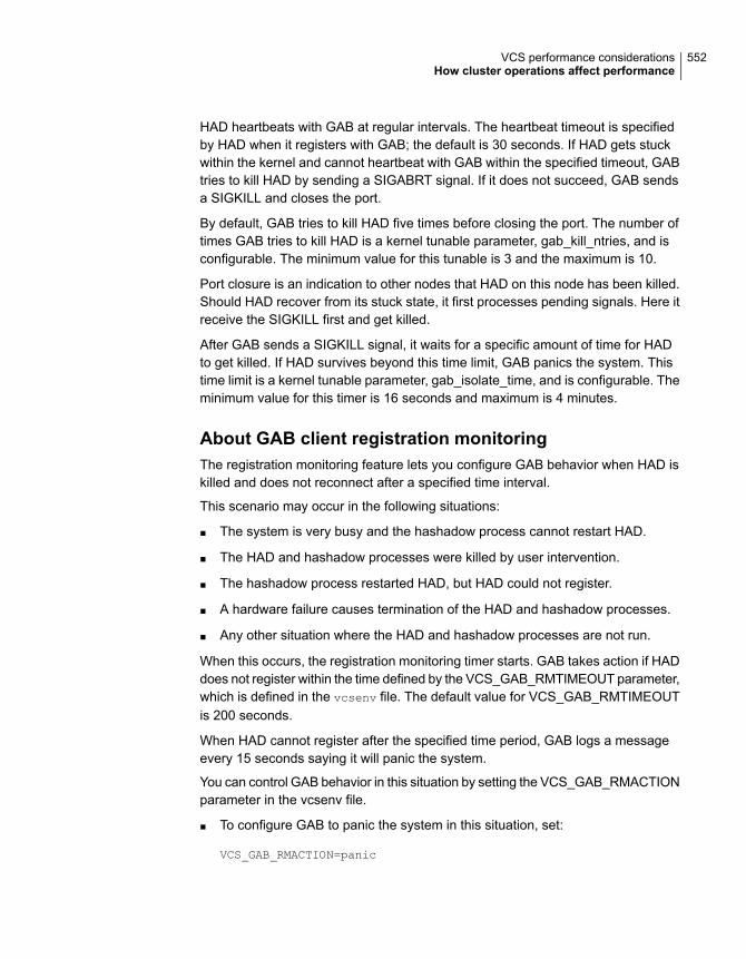
HAD heartbeats with GAB at regular intervals. The heartbeat timeout is specifiedby HAD when it registers with GAB; the default is 30 seconds. If HAD gets stuckwithin the kernel and cannot heartbeat with GAB within the specified timeout, GABtries to kill HAD by sending a SIGABRT signal. If it does not succeed, GAB sendsa SIGKILL and closes the port.
By default, GAB tries to kill HAD five times before closing the port. The number oftimes GAB tries to kill HAD is a kernel tunable parameter, gab_kill_ntries, and isconfigurable. The minimum value for this tunable is 3 and the maximum is 10.
Port closure is an indication to other nodes that HAD on this node has been killed.Should HAD recover from its stuck state, it first processes pending signals. Here itreceive the SIGKILL first and get killed.
After GAB sends a SIGKILL signal, it waits for a specific amount of time for HADto get killed. If HAD survives beyond this time limit, GAB panics the system. Thistime limit is a kernel tunable parameter, gab_isolate_time, and is configurable. Theminimum value for this timer is 16 seconds and maximum is 4 minutes.
About GAB client registration monitoringThe registration monitoring feature lets you configure GAB behavior when HAD iskilled and does not reconnect after a specified time interval.
This scenario may occur in the following situations:
■ The system is very busy and the hashadow process cannot restart HAD.
■ The HAD and hashadow processes were killed by user intervention.
■ The hashadow process restarted HAD, but HAD could not register.
■ A hardware failure causes termination of the HAD and hashadow processes.
■ Any other situation where the HAD and hashadow processes are not run.
When this occurs, the registration monitoring timer starts. GAB takes action if HADdoes not register within the time defined by the VCS_GAB_RMTIMEOUT parameter,which is defined in the vcsenv file. The default value for VCS_GAB_RMTIMEOUTis 200 seconds.
When HAD cannot register after the specified time period, GAB logs a messageevery 15 seconds saying it will panic the system.
You can control GAB behavior in this situation by setting the VCS_GAB_RMACTIONparameter in the vcsenv file.
■ To configure GAB to panic the system in this situation, set:
VCS_GAB_RMACTION=panic
552VCS performance considerationsHow cluster operations affect performance

In this configuration, killing the HAD and hashadow processes results in a panicunless you start HAD within the registration monitoring timeout interval.
■ To configure GAB to log a message in this situation, set:
VCS_GAB_RMACTION=SYSLOG
The default value of this parameter is SYSLOG, which configures GAB to log amessage when HAD does not reconnect after the specified time interval.In this scenario, you can choose to restart HAD (using hastart) or unconfigureGAB (using gabconfig -U).
When you enable registration monitoring, GAB takes no action if the HAD processunregisters with GAB normally, that is if you stop HAD using the hastop command.
About network failure and GAB IOFENCE messageIf a network partition occurs, a cluster can split into two or more separatesub-clusters. When two clusters join as one, GAB ejects one sub-cluster. GABprints diagnostic messages and sends iofence messages to the sub-cluster beingejected.
The systems in the sub-cluster process the iofence messages depending on thetype of GAB port that a user client process or a kernel module uses:
■ If the GAB client is a user process, then GAB tries to kill the client process.
■ If the GAB client is a kernel module, then GAB panics the system.
The gabconfig command's -k and -j options apply to the user client processes.The -k option prevents GAB from panicking the system when it cannot kill the userprocesses. The -j option panics the system and does not kill the user processwhen GAB receives the iofence message.
About quick reopenIf a system leaves cluster and tries to join the cluster before the new cluster isconfigured (default is five seconds), the system is sent an iofence message withreason set to "quick reopen”. When the system receives the message, it tries to killthe client process.
VCS performance consideration when a service group switches overThe time it takes to switch a service group equals the time to offline a service groupon the source system, plus the time to bring the service group online on the targetsystem.
553VCS performance considerationsHow cluster operations affect performance

VCS performance consideration when a service group fails overThe time it takes to fail over a service group when a resource faults equals thefollowing:
■ The time it takes to detect the resource fault
■ The time it takes to offline the service group on source system
■ The time it takes for the VCS policy module to select target system
■ The time it takes to bring the service group online on target system
The time it takes to fail over a service group when a system faults equals thefollowing:
■ The time it takes to detect system fault
■ The time it takes to offline the dependent service groups on other runningsystems
■ The time it takes for the VCS policy module to select target system
■ The time it takes to bring the service group online on target system
The time it takes the VCS policy module to determine the target system is negligiblein comparison to the other factors.
If you have a firm group dependency and the child group faults, VCS offlines allimmediate and non-immediate parent groups before bringing the child group onlineon the target system. Therefore, the time it takes a parent group to be broughtonline also depends on the time it takes the child group to be brought online.
About scheduling class and priority configurationVCS allows you to specify priorities and scheduling classes for VCS processes.VCS supports the following scheduling classes:
■ RealTime (specified as "RT in the configuration file)
■ TimeSharing (specified as "TS in the configuration file)
About priority rangesTable 20-1 displays the platform-specific priority range for RealTime, TimeSharing,and SRM scheduling (SHR) processes.
554VCS performance considerationsAbout scheduling class and priority configuration

Table 20-1 Priority ranges
Priority range using #ps commandsDefault priorityrange wWeak /strong
Schedulingclass
Platform
126 / 50
Priority varies with CPU consumption.
Note: On AIX, use #ps -ael
126 / 50
60
RT
TS
AIX
Default scheduling classes and prioritiesTable 20-2 lists the default class and priority values used by VCS. The class andpriority of trigger processes are determined by the attributes ProcessClass (default= TS) and ProcessPriority (default = ""). Both attributes can be modified accordingto the class and priority at which the trigger processes run.
Table 20-2 Default scheduling classes and priorities
ScriptAgentProcesscreated byengine
EngineProcess
TSTSTSRTDefault scheduling class
00052 (Strongest+ 2)
Default priority (AIX)
Note: For standard configurations, Veritas recommends using the default valuesfor scheduling unless specific configuration requirements dictate otherwise.
Note that the default priority value is platform-specific. When priority is set to ""(empty string), VCS converts the priority to a value specific to the platform on whichthe system is running. For TS, the default priority equals the strongest prioritysupported by the TimeSharing class. For RT, the default priority equals two lessthan the strongest priority supported by the RealTime class. So, if the strongestpriority supported by the RealTime class is 59, the default priority for the RT classis 57.
555VCS performance considerationsAbout scheduling class and priority configuration

About configuring priorities for LLT threads for AIXIn an highly loaded system, LLT threads might not be able to run because ofrelatively low priority settings. This situation may result in heartbeat failures acrosscluster nodes.
You can modify the priorities for the timer and service threads by configuring kerneltunables in the file /etc/llt.conf.
Following is a sample llt.conf file:
llt_maxnids=32
llt_maxports=32
llt_nominpad=0
llt_basetimer=50000
llt_thread_pri=40
Table 20-3 depicts the priorities for LLT threads for AIX.
Table 20-3 Priorities for LLT threads for AIX
Tunable to configure threadpriority
Priorityrange
Defaultpriority
LLT thread
llt_thread_pri40 to 6040LLT service thread
Note that the priorities must lie within the priority range. If you specify a priorityoutside the range, LLT resets it to a value within the range.
To specify priorities for LLT threads
◆ Specify priorities for these tunables by setting the following entries in the file/etc/llt.conf:
llt_thread_pri=<priority value>
Note that these changes take effect when the LLT module reloads.
CPU binding of HADIn certain situations, the AIX operating systems may assign high priority interruptthreads to the logical CPU on which HAD is running, thereby interrupting HAD.
In this scenario, HAD cannot function until the interrupt handler completes itsoperation.
556VCS performance considerationsCPU binding of HAD

To overcome this issue, VCS provides the option of running HAD on a specificlogical processor. VCS disables all interrupts on that logical processor. ConfigureHAD to run on a specific logical processor by setting the CPUBinding attribute.
Note: CPU binding of HAD is supported only on AIX 6.1 TL6 or later and AIX 7.1.
See System attributes on page 707.
Use the following command to modify the CPUBinding attribute:
hasys -modify sys1 CPUBinding BindTo
NONE|ANY|CPUNUM [CPUNumber number]
where:
■ The value NONE indicates that HAD does not use CPU binding.
■ The value ANY indicates that HAD binds to any available logical CPU.
■ The value CPUNUM indicates that HAD binds to the logical CPU specified inthe CPUNumber attribute.The variable number specifies the serial number of the logical CPU.
Warning: Veritas recommends that you modify CPUBinding on the local system.If you specify an invalid processor number when you try to bind HAD to aprocessor on remote system, HAD does not bind to any CPU. The commanddisplays no error that the CPU does not exist.
Note: You cannot use the -add, -update, or -delete [-keys] options for the hasys-modify command to modify the CPUBinding attribute.
In certain scenarios, when HAD is killed or is not running, the logical CPU interruptsmight remain disabled. However, you can enable the interrupts manually. To checkfor the logical processor IDs that have interrupts disabled, run the followingcommand:
# cpuextintr_ctl -q disable
To enable interrupts on a logical processor ID, run the following command:
# cpuextintr_ctl -C processor_id -i enable
557VCS performance considerationsCPU binding of HAD

VCS agent statisticsYou can configure VCS to track the time taken for monitoring resources.
You can use these statistics to configure the MonitorTimeout attribute.
You can also detect potential problems with resources and systems on whichresources are online by analyzing the trends in the time taken by the resource'smonitor cycle. Note that VCS keeps track of monitor cycle times for online resourcesonly.
VCS calculates the time taken for a monitor cycle to complete and computes anaverage of monitor times after a specific number of monitor cycles and stores theaverage in a resource-level attribute.
VCS also tracks increasing trends in the monitor cycle times and sends notificationsabout sudden and gradual increases in monitor times.
VCS uses the following parameters to compute the average monitor time and todetect increasing trends in monitor cycle times:
■ Frequency: The number of monitor cycles after which the monitor time averageis computed and sent to the VCS engine.For example, if Frequency is set to 10, VCS computes the average monitor timeafter every 10 monitor cycles.
■ ExpectedValue: The expected monitor time (in milliseconds) for a resource.VCS sends a notification if the actual monitor time exceeds the expected monitortime by the ValueThreshold. So, if you set this attribute to 5000 for a FileOnOffresource, and if ValueThreshold is set to 40%, VCS will send a notification onlywhen the monitor cycle for the FileOnOff resource exceeds the expected timeby over 40%, that is 7000 milliseconds.
■ ValueThreshold: The maximum permissible deviation (in percent) from theexpected monitor time. When the time for a monitor cycle exceeds this limit,VCS sends a notification about the sudden increase or decrease in monitortime.For example, a value of 100 means that VCS sends a notification if the actualmonitor time deviates from the expected time by over 100%.VCS sends these notifications conservatively. If 12 consecutive monitor cyclesexceed the threshold limit, VCS sends a notification for the first spike, and thena collective notification for the next 10 consecutive spikes.
■ AvgThreshold: The threshold value (in percent) for increase in the averagemonitor cycle time for a resource.VCS maintains a running average of the time taken by the monitor cycles of aresource. The first such computed running average is used as a benchmarkaverage. If the current running average for a resource differs from the benchmark
558VCS performance considerationsVCS agent statistics

average by more than this threshold value, VCS regards this as a sign of gradualincrease or decrease in monitor cycle times and sends a notification about it forthe resource. Whenever such an event occurs, VCS resets the internallymaintained benchmark average to this new average. VCS sends notificationsregardless of whether the deviation is an increase or decrease in the monitorcycle time.For example, a value of 25 means that if the actual average monitor time is 25%more than the benchmark monitor time average, VCS sends a notification.
Tracking monitor cycle timesVCS marks sudden changes in monitor times by comparing the time taken for eachmonitor cycle with the ExpectedValue. If this difference exceeds the ValueThreshold,VCS sends a notification about the sudden change in monitor time. Note that VCSsends this notification only if monitor time increases.
VCS marks gradual changes in monitor times by comparing the benchmark averageand the moving average of monitor cycle times. VCS computes the benchmarkaverage after a certain number of monitor cycles and computes the moving averageafter every monitor cycle. If the current moving average exceeds the benchmarkaverage by more than the AvgThreshold, VCS sends a notification about this gradualchange in the monitor cycle time.
VCS attributes enabling agent statisticsThis topic describes the attributes that enable VCS agent statistics.
559VCS performance considerationsVCS agent statistics

A resource type-level attribute, which stores the required parametervalues for calculating monitor time statistics.
static str MonitorStatsParam = { Frequency = 10,ExpectedValue = 3000, ValueThreshold = 100,AvgThreshold = 40 }
■ Frequency: Defines the number of monitor cycles after which theaverage monitor cycle time should be computed and sent to theengine. If configured, the value for this attribute must be between1 and 30. It is set to 0 by default.
■ ExpectedValue: The expected monitor time in milliseconds for allresources of this type. Default=3000.
■ ValueThreshold: The acceptable percentage difference betweenthe expected monitor cycle time (ExpectedValue) and the actualmonitor cycle time. Default=100.
■ AvgThreshold: The acceptable percentage difference between thebenchmark average and the moving average of monitor cycle times.Default=40
MonitorStatsParam
Stores the average time taken by a number of monitor cycles specifiedby the Frequency attribute along with a timestamp value of when theaverage was computed.
str MonitorTimeStats{} = { Avg = "0", TS = "" }
This attribute is updated periodically after a number of monitor cyclesspecified by the Frequency attribute. If Frequency is set to 10, theattribute stores the average of 10 monitor cycle times and is updatedafter every 10 monitor cycles.
The default value for this attribute is 0.
MonitorTimeStats
A flag that specifies whether VCS keeps track of the monitor times forthe resource.
boolean ComputeStats = 0
The value 0 indicates that VCS will not keep track of the time taken bythe monitor routine for the resource. The value 1 indicates that VCSkeeps track of the monitor time for the resource.
The default value for this attribute is 0.
ComputeStats
About VCS tunable parametersVCS has some tunable parameters that you can configure to enhance theperformance of specific features. However, Veritas Technologies recommends that
560VCS performance considerationsAbout VCS tunable parameters

the user not change the tunable kernel parameters without assistance from VeritasTechnologies support personnel. Several of the tunable parameters preallocatememory for critical data structures, and a change in their values could increasememory use or degrade performance.
Warning: Do not adjust the VCS tunable parameters for kernel modules such asVXFEN without assistance from Veritas Technologies support personnel.
About LLT tunable parametersLLT provides various configuration and tunable parameters to modify and controlthe behavior of the LLT module. This section describes some of the LLT tunableparameters that can be changed at run-time and at LLT start-time.
See “About Low Latency Transport (LLT)” on page 217.
The tunable parameters are classified into two categories:
■ LLT timer tunable parametersSee “About LLT timer tunable parameters” on page 561.
■ LLT flow control tunable parametersSee “About LLT flow control tunable parameters” on page 565.
See “Setting LLT timer tunable parameters” on page 568.
About LLT timer tunable parametersTable 20-4 lists the LLT timer tunable parameters. The timer values are set in .01sec units. The command lltconfig –T query can be used to display current timervalues.
561VCS performance considerationsAbout VCS tunable parameters

Table 20-4 LLT timer tunable parameters
Dependency with otherLLT tunable parameters
When to changeDefaultDescriptionLLTparameter
The timer value shouldalways be higher than thepeertrouble timer value.
■ Change this value fordelaying or speeding upnode/link inactivenotification mechanism asper client’s notificationprocessing logic.
■ Increase the value forplanned replacement offaulty network cable/switch.
■ In some circumstances,when the private networkslinks are very slow or thenetwork traffic becomesvery bursty, increase thisvalue so as to avoid falsenotifications of peer death.Set the value to a highvalue for plannedreplacement of faultynetwork cable or faultyswitch.
3200LLT marks a link of a peernode as “inactive," if it doesnot receive any packet on thatlink for this timer interval.Once a link is marked as"inactive," LLT will not sendany data on that link.
peerinact
This timer value shouldalways be lower thanpeerinact timer value. Also, Itshould be close to its defaultvalue.
■ In some circumstances,when the private networkslinks are very slow ornodes in the cluster arevery busy, increase thevalue.
■ Increase the value forplanned replacement offaulty network cable /faultyswitch.
200LLT marks a high-pri link of apeer node as "troubled", if itdoes not receive any packeton that link for this timerinterval. Once a link ismarked as "troubled", LLT willnot send any data on that linktill the link is up.
peertrouble
562VCS performance considerationsAbout VCS tunable parameters

Table 20-4 LLT timer tunable parameters (continued)
Dependency with otherLLT tunable parameters
When to changeDefaultDescriptionLLTparameter
This timer value shouldalways be lower thanpeerinact timer value. Also, Itshould be close to its defaultvalue.
■ In some circumstances,when the private networkslinks are very slow ornodes in the cluster arevery busy, increase thevalue.
■ Increase the value forplanned replacement offaulty network cable /faultyswitch.
400LLT marks a low-pri link of apeer node as "troubled", if itdoes not receive any packeton that link for this timerinterval. Once a link ismarked as "troubled", LLT willnot send any data on that linktill the link is available.
peertroublelo
This timer value should belower than peertrouble timervalue. Also, it should not beclose to peertrouble timervalue.
In some circumstances, whenthe private networks links arevery slow (or congested) ornodes in the cluster are verybusy, increase the value.
50LLT sends heartbeat packetsrepeatedly to peer nodes afterevery heartbeat timer intervalon each highpri link.
heartbeat
This timer value should belower than peertroublelo timervalue. Also, it should not beclose to peertroublelo timervalue.
In some circumstances, whenthe networks links are veryslow or nodes in the clusterare very busy, increase thevalue.
100LLT sends heartbeat packetsrepeatedly to peer nodes afterevery heartbeatlo timerinterval on each low pri link.
heartbeatlo
This timer is set to ‘peerinact- 200’ automatically everytime when the peerinact timeris changed.
Decrease the value of thistunable for speeding upnode/link inactive notificationmechanism as per client’snotification processing logic.
Disable the request heartbeatmechanism by setting thevalue of this timer to 0 forplanned replacement of faultynetwork cable /switch.
In some circumstances, whenthe private networks links arevery slow or the networktraffic becomes very bursty,don’t change the value of thistimer tunable.
3000If LLT does not receive anypacket from the peer node ona particular link for"timetoreqhb" time period, itattempts to requestheartbeats (sends 5 specialheartbeat requests (hbreqs)to the peer node on the samelink) from the peer node. If thepeer node does not respondto the special heartbeatrequests, LLT marks the linkas “expired” for that peernode. The value can be setfrom the range of 0 to(peerinact -200). The value 0disables the requestheartbeat mechanism.
timetoreqhb
563VCS performance considerationsAbout VCS tunable parameters

Table 20-4 LLT timer tunable parameters (continued)
Dependency with otherLLT tunable parameters
When to changeDefaultDescriptionLLTparameter
Not applicableVeritas does not recommendto change this value
40This value specifies the timeinterval between twosuccessive special heartbeatrequests. See thetimetoreqhb parameter formore information on specialheartbeat requests.
reqhbtime
This timer value should notbe more than peerinact timervalue. Also, it should not beclose to the peerinact timervalue.
Disable the out of timercontext heart-beatingmechanism by setting thevalue of this timer to 0 forplanned replacement of faultynetwork cable /switch.
In some circumstances, whenthe private networks links arevery slow or nodes in thecluster are very busy,increase the value
200LLT sends out of timercontext heartbeats to keepthe node alive when LLTtimer does not run at regularinterval. This option specifiesthe amount of time to waitbefore sending a heartbeat incase of timer not running.
If this timer tunable is set to0, the out of timer contextheartbeating mechanism isdisabled.
timetosendhb
NAVeritas does not recommendthis value.
18000This value specifies themaximum time for which LLTwill send contiguous out oftimer context heartbeats.
sendhbcap
Not applicableDo not change this value forperformance reasons.Lowering the value can resultin unnecessaryretransmissions/negativeacknowledgement traffic.
You can increase the valueof oos if the round trip time islarge in the cluster (forexample, campus cluster).
10If the out-of-sequence timerhas expired for a node, LLTsends an appropriate NAK tothat node. LLT does not senda NAK as soon as it receivesan oos packet. It waits for theoos timer value beforesending the NAK.
oos
564VCS performance considerationsAbout VCS tunable parameters

Table 20-4 LLT timer tunable parameters (continued)
Dependency with otherLLT tunable parameters
When to changeDefaultDescriptionLLTparameter
Not applicableDo not change this value.Lowering the value can resultin unnecessaryretransmissions.
You can increase the valueof retrans if the round trip timeis large in the cluster (forexample, campus cluster).
10LLT retransmits a packet if itdoes not receive itsacknowledgement for thistimer interval value.
retrans
Not applicableDo not change this value forperformance reasons.
100LLT calls its service routine(which delivers messages toLLT clients) after everyservice timer interval.
service
Not applicableThis feature is disabled bydefault.
0LLT flushes stored addressof peer nodes when this timerexpires and relearns theaddresses.
arp
Not applicableDo not change this value forperformance reasons.
3000LLT sends an arp requestwhen this timer expires todetect other peer nodes in thecluster.
arpreq
About LLT flow control tunable parametersTable 20-5 lists the LLT flow control tunable parameters. The flow control valuesare set in number of packets. The command lltconfig -F query can be usedto display current flow control settings.
565VCS performance considerationsAbout VCS tunable parameters
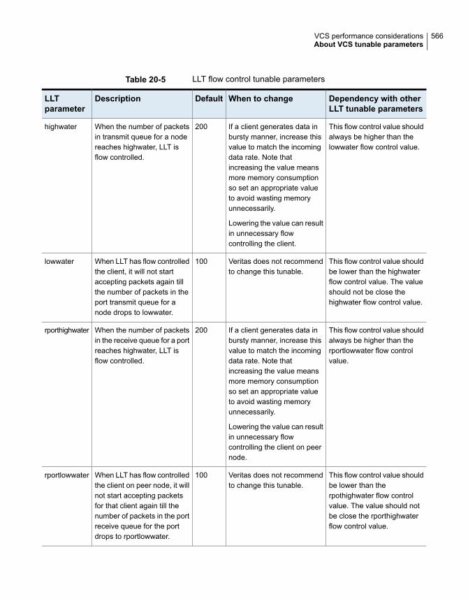
Table 20-5 LLT flow control tunable parameters
Dependency with otherLLT tunable parameters
When to changeDefaultDescriptionLLTparameter
This flow control value shouldalways be higher than thelowwater flow control value.
If a client generates data inbursty manner, increase thisvalue to match the incomingdata rate. Note thatincreasing the value meansmore memory consumptionso set an appropriate valueto avoid wasting memoryunnecessarily.
Lowering the value can resultin unnecessary flowcontrolling the client.
200When the number of packetsin transmit queue for a nodereaches highwater, LLT isflow controlled.
highwater
This flow control value shouldbe lower than the highwaterflow control value. The valueshould not be close thehighwater flow control value.
Veritas does not recommendto change this tunable.
100When LLT has flow controlledthe client, it will not startaccepting packets again tillthe number of packets in theport transmit queue for anode drops to lowwater.
lowwater
This flow control value shouldalways be higher than therportlowwater flow controlvalue.
If a client generates data inbursty manner, increase thisvalue to match the incomingdata rate. Note thatincreasing the value meansmore memory consumptionso set an appropriate valueto avoid wasting memoryunnecessarily.
Lowering the value can resultin unnecessary flowcontrolling the client on peernode.
200When the number of packetsin the receive queue for a portreaches highwater, LLT isflow controlled.
rporthighwater
This flow control value shouldbe lower than therpothighwater flow controlvalue. The value should notbe close the rporthighwaterflow control value.
Veritas does not recommendto change this tunable.
100When LLT has flow controlledthe client on peer node, it willnot start accepting packetsfor that client again till thenumber of packets in the portreceive queue for the portdrops to rportlowwater.
rportlowwater
566VCS performance considerationsAbout VCS tunable parameters

Table 20-5 LLT flow control tunable parameters (continued)
Dependency with otherLLT tunable parameters
When to changeDefaultDescriptionLLTparameter
This flow control value shouldnot be higher than thedifference between thehighwater flow control valueand the lowwater flow controlvalue.
The value of this parameter(window) should be alignedwith the value of thebandwidth delay product.
Change the value as per theprivate networks speed.Lowering the valueirrespective of network speedmay result in unnecessaryretransmission of out ofwindow sequence packets.
50This is the maximum numberof un-ACKed packets LLT willput in flight.
window
This flow control value shouldnot be higher than thedifference between thehighwater flow control valueand the lowwater flow controlvalue.
For performance reasons, itsvalue should be either 0 or atleast 32.
32It represents the number ofback-to-back packets thatLLT sends on a link beforethe next link is chosen.
linkburst
Not applicableDo not change this value forperformance reasons.Increasing the value canresult in unnecessaryretransmissions.
10LLT sends acknowledgementof a packet by piggybackingan ACK packet on the nextoutbound data packet to thesender node. If there are nodata packets on which topiggyback the ACK packet,LLT waits for ackval numberof packets before sending anexplicit ACK to the sender.
ackval
Its value should be lower thanthat of window. Its valueshould be close to the valueof window tunable.
For performance reason, itsvalue should be changedwhenever the value of thewindow tunable is changedas per the formula givenbelow: sws = window *4/5.
40To avoid Silly WindowSyndrome, LLT transmitsmore packets only when thecount of un-acked packetgoes to below of this tunablevalue.
sws
Not applicableVeritas does not recommendto change this tunable.
1024When LLT has packets todelivers to multiple ports, LLTdelivers one large packet orup to five small packets to aport at a time. This parameterspecifies the size of the largepacket.
largepktlen
567VCS performance considerationsAbout VCS tunable parameters

Setting LLT timer tunable parametersYou can set the LLT tunable parameters either with the lltconfig command or inthe /etc/llttab file. You can use the lltconfig command to change a parameteron the local node at run time. Veritas recommends you run the command on all thenodes in the cluster to change the values of the parameters. To set an LLTparameter across system reboots, you must include the parameter definition in the/etc/llttab file. Default values of the parameters are taken if nothing is specifiedin /etc/llttab. The parameters values specified in the /etc/llttab file come into effectat LLT start-time only. Veritas recommends that you specify the same definition ofthe tunable parameters in the /etc/llttab file of each node.
To get and set a timer tunable:
■ To get the current list of timer tunable parameters using lltconfig command:
# lltconfig -T query
■ To set a timer tunable parameter using the lltconfig command:
# lltconfig -T timer tunable:value
■ To set a timer tunable parameter in the /etc/llttab file:
set-timer timer tunable:value
To get and set a flow control tunable
■ To get the current list of flow control tunable parameters using lltconfig command:
# lltconfig -F query
■ To set a flow control tunable parameter using the lltconfig command:
# lltconfig -F flowcontrol tunable:value
■ To set a flow control tunable parameter in the /etc/llttab file:
set-flow flowcontrol tunable:value
See the lltconfig(1M) and llttab(1M) manual pages.
About GAB tunable parametersGAB provides various configuration and tunable parameters to modify and controlthe behavior of the GAB module.
568VCS performance considerationsAbout VCS tunable parameters

See “About Group Membership Services/Atomic Broadcast (GAB)” on page 216.
These tunable parameters not only provide control of the configurations likemaximum possible number of nodes in the cluster, but also provide control on howGAB behaves when it encounters a fault or a failure condition. Some of thesetunable parameters are needed when the GAB module is loaded into the system.Any changes to these load-time tunable parameters require either unload followedby reload of GAB module or system reboot. Other tunable parameters (run-time)can be changed while GAB module is loaded, configured, and cluster is running.Any changes to such a tunable parameter will have immediate effect on the tunableparameter values and GAB behavior.
See “About GAB load-time or static tunable parameters” on page 569.
See “About GAB run-time or dynamic tunable parameters” on page 571.
About GAB load-time or static tunable parametersTable 20-6 lists the static tunable parameters in GAB that are used during moduleload time. Use the gabconfig -e command to list all such GAB tunable parameters.
You can modify these tunable parameters only by adding new values in the GABconfiguration file. The changes take effect only on reboot or on reload of the GABmodule.
Table 20-6 GAB static tunable parameters
Values (defaultand range)
DescriptionGAB parameter
Default: 64
Range: 64
Maximum number of nodes in the clusternumnids
Default: 32
Range: 1-32
Maximum number of ports in the clusternumports
Default: 128
Range: 1-1024
Number of pending messages in GABqueues (send or receive) before GABhits flow control.
This can be overwritten while cluster isup and running with the gabconfig-Q option. Use the gabconfigcommand to control value of thistunable.
flowctrl
569VCS performance considerationsAbout VCS tunable parameters

Table 20-6 GAB static tunable parameters (continued)
Values (defaultand range)
DescriptionGAB parameter
Default: 48100
Range:8100-65400
GAB internal log buffer size in byteslogbufsize
Default: 256
Range: 128-4096
Maximum messages in internalmessage log
msglogsize
Default: 120000msec (2 minutes)
Range:160000-240000 (inmsec)
Maximum time to wait for isolated client
Can be overridden at runtime
See “About GAB run-time or dynamictunable parameters” on page 571.
isolate_time
Default: 5
Range: 3-10
Number of times to attempt to kill client
Can be overridden at runtime
See “About GAB run-time or dynamictunable parameters” on page 571.
kill_ntries
Default: 12
Range: 1-256
Maximum number of wait periods (asdefined in the stable timeout parameter)before GAB disconnects the node fromthe cluster during cluster reconfiguration
conn_wait
Default: 8
Range: 0-32
Determines whether the GAB loggingdaemon is enabled or disabled
The GAB logging daemon is enabled bydefault. To disable, change the value ofgab_ibuf_count to 0.
The disable login to the gab daemonwhile cluster is up and running with thegabconfig -K option. Use thegabconfig command to control valueof this tunable.
ibuf_count
Default: 17
Range: 2-60
Priority of GAB timer thread on AIXtimer_pri
570VCS performance considerationsAbout VCS tunable parameters

About GAB run-time or dynamic tunable parametersYou can change the GAB dynamic tunable parameters while GAB is configuredand while the cluster is running. The changes take effect immediately on runningthe gabconfig command. Note that some of these parameters also control howGAB behaves when it encounters a fault or a failure condition. Some of theseconditions can trigger a PANIC which is aimed at preventing data corruption.
You can display the default values using the gabconfig -l command. To makechanges to these values persistent across reboots, you can append the appropriatecommand options to the /etc/gabtab file along with any existing options. Forexample, you can add the -k option to an existing /etc/gabtab file that might readas follows:
gabconfig -c -n4
After adding the option, the /etc/gabtab file looks similar to the following:
gabconfig -c -n4 -k
Table 20-7 describes the GAB dynamic tunable parameters as seen with thegabconfig -l command, and specifies the command to modify them.
Table 20-7 GAB dynamic tunable parameters
Description and commandGAB parameter
This option defines the minimum number of nodes that can form thecluster. This option controls the forming of the cluster. If the number ofnodes in the cluster is less than the number specified in the gabtabfile, then the cluster will not form. For example: if you type gabconfig-c -n4, then the cluster will not form until all four nodes join the cluster.If this option is enabled using the gabconfig -x command then thenode will join the cluster even if the other nodes in the cluster are notyet part of the membership.
Use the following command to set the number of nodes that can formthe cluster:
gabconfig -n count
Use the following command to enable control port seed. Node can formthe cluster without waiting for other nodes for membership:
gabconfig -x
Control port seed
571VCS performance considerationsAbout VCS tunable parameters

Table 20-7 GAB dynamic tunable parameters (continued)
Description and commandGAB parameter
Default: Disabled
This option controls GAB's ability to halt (panic) the system on userprocess death. If _had and _hashadow are killed using kill -9, thesystem can potentially lose high availability. If you enable this option,then the GAB will PANIC the system on detecting the death of the clientprocess. The default behavior is to disable this option.
Use the following command to enable halt system on process death:
gabconfig -p
Use the following command to disable halt system on process death:
gabconfig -P
Halt on processdeath
Default: Disabled
If this option is enabled then the system will panic on missing the firstheartbeat from the VCS engine or the vxconfigd daemon in a CVMenvironment. The default option is to disable the immediate panic.
This GAB option controls whether GAB can panic the node or not whenthe VCS engine or the vxconfigd daemon miss to heartbeat with GAB.If the VCS engine experiences a hang and is unable to heartbeat withGAB, then GAB will NOT PANIC the system immediately. GAB will firsttry to abort the process by sending SIGABRT (kill_ntries - default value5 times) times after an interval of "iofence_timeout" (default value 15seconds). If this fails, then GAB will wait for the "isolate timeout" periodwhich is controlled by a global tunable called isolate_time (default value2 minutes). If the process is still alive, then GAB will PANIC the system.
If this option is enabled GAB will immediately HALT the system in caseof missed heartbeat from client.
Use the following command to enable system halt when processheartbeat fails:
gabconfig -b
Use the following command to disable system halt when processheartbeat fails:
gabconfig -B
Missed heartbeathalt
572VCS performance considerationsAbout VCS tunable parameters

Table 20-7 GAB dynamic tunable parameters (continued)
Description and commandGAB parameter
Default: Disabled
This option allows the user to configure the behavior of the VCS engineor any other user process when one or more nodes rejoin a cluster aftera network partition. By default GAB will not PANIC the node runningthe VCS engine. GAB kills the userland process (the VCS engine orthe vxconfigd process). This recycles the user port (port h in case ofthe VCS engine) and clears up messages with the old generationnumber programmatically. Restart of the process, if required, must behandled outside of GAB control, e.g., for hashadow process restarts_had.
When GAB has kernel clients (such as fencing, VxVM, or VxFS), thenthe node will always PANIC when it rejoins the cluster after a networkpartition. The PANIC is mandatory since this is the only way GAB canclear ports and remove old messages.
Use the following command to enable system halt on rejoin:
gabconfig -j
Use the following command to disable system halt on rejoin:
gabconfig -J
Halt on rejoin
Default: Disabled
If this option is enabled, then GAB prevents the system fromPANICKING when the VCS engine or the vxconfigd process fail toheartbeat with GAB and GAB fails to kill the VCS engine or the vxconfigdprocess. GAB will try to continuously kill the VCS engine and will notpanic if the kill fails.
Repeat attempts to kill process if it does not die
gabconfig -k
Keep on killing
573VCS performance considerationsAbout VCS tunable parameters

Table 20-7 GAB dynamic tunable parameters (continued)
Description and commandGAB parameter
Default: Disabled
This is an option in GAB which allows a node to IOFENCE (resultingin a PANIC) if the new membership set is < 50% of the old membershipset. This option is typically disabled and is used when integrating withother products
Enable iofence quorum
gabconfig -q
Disable iofence quorum
gabconfig -d
Quorum flag
Default: Send queue limit: 128
Default: Recv queue limit: 128
GAB queue limit option controls the number of pending message beforewhich GAB sets flow. Send queue limit controls the number of pendingmessage in GAB send queue. Once GAB reaches this limit it will setflow control for the sender process of the GAB client. GAB receivequeue limit controls the number of pending message in GAB receivequeue before GAB send flow control for the receive side.
Set the send queue limit to specified value
gabconfig -Q sendq:value
Set the receive queue limit to specified value
gabconfig -Q recvq:value
GAB queue limit
Default: 15000(ms)
This parameter specifies the timeout (in milliseconds) for which GABwill wait for the clients to respond to an IOFENCE message beforetaking next action. Based on the value of kill_ntries , GAB will attemptto kill client process by sending SIGABRT signal. If the client processis still registered after GAB attempted to kill client process for the valueof kill_ntries times, GAB will halt the system after waiting for additionalisolate_timeout value.
Set the iofence timeout value to specified value in milliseconds.
gabconfig -f value
IOFENCE timeout
574VCS performance considerationsAbout VCS tunable parameters

Table 20-7 GAB dynamic tunable parameters (continued)
Description and commandGAB parameter
Default: 5000(ms)
Specifies the time GAB waits to reconfigure membership after the lastreport from LLT of a change in the state of local node connections fora given port. Any change in the state of connections will restart GABwaiting period.
Set the stable timeout to specified value
gabconfig -t stable
Stable timeout
Default: 120000(ms)
This tunable specifies the timeout value for which GAB will wait forclient process to unregister in response to GAB sending SIGKILL signal.If the process still exists after isolate timeout GAB will halt the system
gabconfig -S isolate_time:value
Isolate timeout
Default: 5
This tunable specifies the number of attempts GAB will make to kill theprocess by sending SIGABRT signal.
gabconfig -S kill_ntries:value
Kill_ntries
This parameter shows whether GAB is configured. GAB may not haveseeded and formed any membership yet.
Driver state
This parameter shows whether GAB is asked to specifically ignorejeopardy.
See the gabconfig (1M) manual page for details on the -s flag.
Partition arbitration
About VXFEN tunable parametersThe section describes the VXFEN tunable parameters and how to reconfigure theVXFEN module.
Table 20-8 describes the tunable parameters for the VXFEN driver.
575VCS performance considerationsAbout VCS tunable parameters

Table 20-8 VXFEN tunable parameters
Description and Values: Default, Minimum, andMaximum
vxfen Parameter
Size of debug log in bytes
■ ValuesDefault: 524288(512KB)Minimum: 65536(64KB)Maximum: 1048576(1MB)
vxfen_deblog_sz
Specifies the maximum number of seconds that the smallersub-cluster waits before racing with larger sub-clusters for controlof the coordinator disks when a network partition occurs.
This value must be greater than the vxfen_min_delay value.
■ ValuesDefault: 60Minimum: 1Maximum: 600
vxfen_max_delay
Specifies the minimum number of seconds that the smallersub-cluster waits before racing with larger sub-clusters for controlof the coordinator disks when a network partition occurs.
This value must be smaller than or equal to the vxfen_max_delayvalue.
■ ValuesDefault: 1Minimum: 1Maximum: 600
vxfen_min_delay
Specifies the time in seconds that the I/O fencing driver VxFENwaits for the I/O fencing daemon VXFEND to return aftercompleting a given task.
■ ValuesDefault: 60Minimum: 10Maximum: 600
vxfen_vxfnd_tmt
576VCS performance considerationsAbout VCS tunable parameters
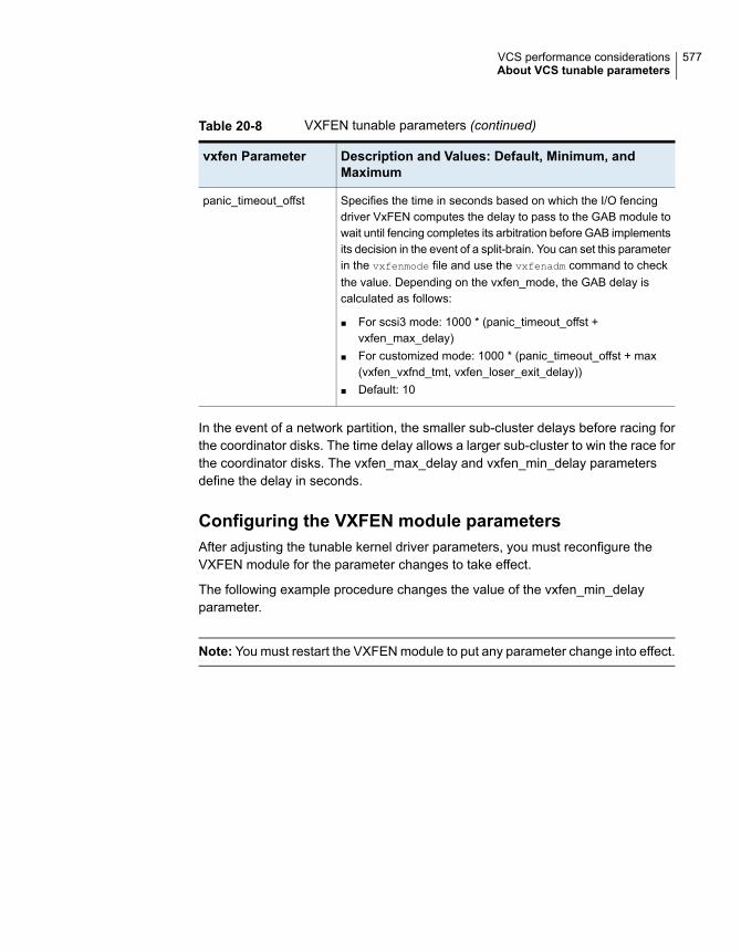
Table 20-8 VXFEN tunable parameters (continued)
Description and Values: Default, Minimum, andMaximum
vxfen Parameter
Specifies the time in seconds based on which the I/O fencingdriver VxFEN computes the delay to pass to the GAB module towait until fencing completes its arbitration before GAB implementsits decision in the event of a split-brain. You can set this parameterin the vxfenmode file and use the vxfenadm command to checkthe value. Depending on the vxfen_mode, the GAB delay iscalculated as follows:
■ For scsi3 mode: 1000 * (panic_timeout_offst +vxfen_max_delay)
■ For customized mode: 1000 * (panic_timeout_offst + max(vxfen_vxfnd_tmt, vxfen_loser_exit_delay))
■ Default: 10
panic_timeout_offst
In the event of a network partition, the smaller sub-cluster delays before racing forthe coordinator disks. The time delay allows a larger sub-cluster to win the race forthe coordinator disks. The vxfen_max_delay and vxfen_min_delay parametersdefine the delay in seconds.
Configuring the VXFEN module parametersAfter adjusting the tunable kernel driver parameters, you must reconfigure theVXFEN module for the parameter changes to take effect.
The following example procedure changes the value of the vxfen_min_delayparameter.
Note: You must restart the VXFEN module to put any parameter change into effect.
577VCS performance considerationsAbout VCS tunable parameters

To configure the VxFEN parameters and reconfigure the VxFEN module
1 Check the status of the driver and start the driver if necessary:
# /etc/methods/vxfenext -status
To start the driver:
# /etc/init.d/vxfen.rc start
2 List the current value of the tunable parameter:
For example:
# lsattr -El vxfen
vxfen_deblog_sz 65536 N/A True
vxfen_max_delay 3 N/A True
vxfen_min_delay 1 N/A True
vxfen_vxfnd_tmt 60 N/A True
The current value of the vxfen_min_delay parameter is 1 (the default).
3 Enter the following command to change the vxfen_min_delay parameter value:
# chdev -l vxfen -P -a vxfen_min_delay=30
4 Ensure that VCS is shut down. Stop I/O fencing if configured.
# /etc/init.d/vxfen.rc stop
5 Ensure that VCS is shut down. Unload and reload the driver after changingthe value of the tunable:
# /etc/methods/vxfenext -stop
# /etc/methods/vxfenext -start
6 Repeat the above steps on each cluster node to change the parameter.
7 Start VCS.
# hastart
About AMF tunable parametersYou can set the Asynchronous Monitoring Framework (AMF) kernel module tunableusing the following command:
578VCS performance considerationsAbout VCS tunable parameters

# amfconfig -T tunable_name=tunable_value,
tunable_name=tunable_value...
Table 20-9 lists the possible tunable parameters for the AMF kernel:
Table 20-9 AMF tunable parameters
ValueDescriptionAMFparameter
Min - 4
Max - 512
Default - 256
AMF maintains an in-memory debug log.This parameter (specified in units of KBs)controls the amount of kernel memoryallocated for this log.
dbglogsz
Min - 64
Max - 8192
Default - 2048
AMF stores registered events in an eventtype specific hash table. This parametercontrols the number of buckets allocatedfor the hash table used to storeprocess-related events.
processhashsz
Min - 64
Max - 8192
Default - 512
AMF stores registered events in an eventtype specific hash table. This parametercontrols the number of buckets allocatedfor the hash table used to storemount-related events.
mnthashsz
Min - 1
Max - 64
Default - 32
AMF stores registered events in an eventtype specific hash table. This parametercontrols the number of buckets allocatedfor the hash table used to storecontainer-related events.
conthashsz
Min - 1
Max - 64
Default - 32
AMF stores registered events in an eventtype specific hash table. This parametercontrols the number of buckets allocatedfor the hash table used to store file-relatedevents.
filehashsz
Min - 1
Max - 64
Default - 32
AMF stores registered events in an eventtype specific hash table. This parametercontrols the number of buckets allocatedfor the hash table used to storedirectory-related events.
dirhashsz
The parameter values that you update are reflected after you reconfigure AMFdriver. Note that if you unload the module, the updated values are lost. You mustunconfigure the module using the amfconfig -U or equivalent command and thenreconfigure using the amfconfig -c command for the updated tunables to be
579VCS performance considerationsAbout VCS tunable parameters

effective. If you want to set the tunables at module load time, you can write theseamfconfig commands in the amftab file.
See the amftab(4) manual page for details.
580VCS performance considerationsAbout VCS tunable parameters

Troubleshooting andrecovery for VCS
This chapter includes the following topics:
■ VCS message logging
■ Troubleshooting the VCS engine
■ Troubleshooting Low Latency Transport (LLT)
■ Troubleshooting Group Membership Services/Atomic Broadcast (GAB)
■ Troubleshooting VCS startup
■ Troubleshooting Intelligent Monitoring Framework (IMF)
■ Troubleshooting service groups
■ Troubleshooting resources
■ Troubleshooting sites
■ Troubleshooting I/O fencing
■ Troubleshooting notification
■ Troubleshooting and recovery for global clusters
■ Troubleshooting the steward process
■ Troubleshooting licensing
■ Troubleshooting secure configurations
■ Troubleshooting wizard-based configuration issues
21Chapter

■ Troubleshooting issues with the Veritas High Availability view
VCS message loggingVCS generates two types of logs: the engine log and the agent log. Log file namesare appended by letters; letter A indicates the first log file, B the second, and C thethird. After three files, the least recent file is removed and another file is created.For example, if engine_A.log is filled to its capacity, it is renamed as engine_B.logand the engine_B.log is renamed as engine_C.log. In this example, the least recentfile is engine_C.log and therefore it is removed. You can update the size of the logfile using the LogSize cluster level attribute.
See “Cluster attributes” on page 722.
The engine log is located at /var/VRTSvcs/log/engine_A.log. The format of enginelog messages is:
Timestamp (Year/MM/DD) | Mnemonic | Severity | UMI | Message Text
■ Timestamp: the date and time the message was generated.
■ Mnemonic: the string ID that represents the product (for example, VCS).
■ Severity: levels include CRITICAL, ERROR, WARNING, NOTICE, and INFO(most to least severe, respectively).
■ UMI: a unique message ID.
■ Message Text: the actual message generated by VCS.
A typical engine log resembles:
2011/07/10 16:08:09 VCS INFO V-16-1-10077 Received new
cluster membership
The agent log is located at /var/VRTSvcs/log/<agent>.log. The format of agentlog messages resembles:
Timestamp (Year/MM/DD) | Mnemonic | Severity | UMI | Agent Type | ResourceName | Entry Point | Message Text
A typical agent log resembles:
2011/07/10 10:38:23 VCS WARNING V-16-2-23331
Oracle:VRT:monitor:Open for ora_lgwr failed, setting
cookie to null.
Note that the logs on all nodes may not be identical because
■ VCS logs local events on the local nodes.
582Troubleshooting and recovery for VCSVCS message logging

■ All nodes may not be running when an event occurs.
VCS prints the warning and error messages to STDERR.
If the VCS engine, Command Server, or any of the VCS agents encounter someproblem, then First Failure Data Capture (FFDC) logs are generated and dumpedalong with other core dumps and stack traces to the following location:
■ For VCS engine: $VCS_DIAG/diag/had
■ For Command Server: $VCS_DIAG/diag/CmdServer
■ For VCS agents: $VCS_DIAG/diag/agents/type, where type represents thespecific agent type.
The default value for variable $VCS_DIAG is /var/VRTSvcs/.
If the debug logging is not turned on, these FFDC logs are useful to analyze theissues that require professional support.
Log unification of VCS agent’s entry pointsEarlier, the logs of VCS agents implemented using script and C/C++ language werescattered between the engine log file and agent log file respectively.
The logging is improved so that logs of all the entry points will be logged in respectiveagent log file. For example, the logs of Mount agent can be found in the Mountagent log file located under /var/VRTSvcs/log directory.
Moreover, using LogViaHalog attribute, user can switch back to the older loggingbehavior. This attribute supports two values 0 and 1. By default the value is 0, whichmeans the agent’s log will go into their respective agent log file. If value is set to 1,then the C/C++ entry point’s logs will go into the agent log file and the script entrypoint’s logs will go into the engine log file using halog command.
Note: Irrespective of the value of LogViaHalog, the script entry point’s logs that areexecuted in the container will go into the engine log file.
Enhancing First Failure Data Capture (FFDC) to troubleshoot VCSresource’s unexpected behavior
FFDC is the process of generating and dumping information on unexpected events.
Earlier, FFDC information is generated on following unexpected events:
■ Segmentation fault
■ When agent fails to heartbeat with engine
583Troubleshooting and recovery for VCSVCS message logging
From VCS 6.2 version, the capturing of the FFDC information on unexpected eventshas been extended to resource level and to cover VCS events. This means, if aresource faces an unexpected behavior then FFDC information will be generated.
The current version enables the agent to log detailed debug logging functions duringunexpected events with respect to resource, such as,
■ Monitor entry point of a resource reported OFFLINE/INTENTIONAL OFFLINEwhen it was in ONLINE state.
■ Monitor entry point of a resource reported UNKNOWN.
■ If any entry point times-out.
■ If any entry point reports failure.
■ When a resource is detected as ONLINE or OFFLINE for the first time.
Now whenever an unexpected event occurs FFDC information will be automaticallygenerated. And this information will be logged in their respective agent log file.
GAB message loggingIf GAB encounters some problem, then First Failure Data Capture (FFDC) logs arealso generated and dumped.
When you have configured GAB, GAB also starts a GAB logging daemon(/opt/VRTSgab/gablogd). GAB logging daemon is enabled by default. You canchange the value of the GAB tunable parameter gab_ibuf_count to disable theGAB logging daemon.
See “About GAB load-time or static tunable parameters” on page 569.
This GAB logging daemon collects the GAB related logs when a critical events suchas an iofence or failure of the master of any GAB port occur, and stores the datain a compact binary form. You can use the gabread_ffdc utility as follows to readthe GAB binary log files:
/opt/VRTSgab/gabread_ffdc binary_logs_files_location
You can change the values of the following environment variables that control theGAB binary log files:
■ GAB_FFDC_MAX_INDX: Defines the maximum number of GAB binary log filesThe GAB logging daemon collects the defined number of log files each of eightMB size. The default value is 20, and the files are named gablog.1 throughgablog.20. At any point in time, the most recent file is the gablog.1 file.
■ GAB_FFDC_LOGDIR: Defines the log directory location for GAB binary log filesThe default location is:
584Troubleshooting and recovery for VCSVCS message logging

/var/adm/gab_ffdc
Note that the gablog daemon writes its log to the glgd_A.log and glgd_B.log
files in the same directory.
You can either define these variables in the following GAB startup file or use theexport command. You must restart GAB for the changes to take effect.
/etc/default/gab
Enabling debug logs for agentsThis section describes how to enable debug logs for VCS agents.
To enable debug logs for agents
1 Set the configuration to read-write:
# haconf -makerw
2 Enable logging and set the desired log levels. Use the following commandsyntax:
# hatype -modify $typename LogDbg DBG_1 DBG_2 DBG_4 DBG_21
The following example shows the command line for the IPMultiNIC resourcetype.
# hatype -modify IPMultiNIC LogDbg DBG_1 DBG_2 DBG_4 DBG_21
See the description of the LogDbg attribute for more information.
See “Resource type attributes” on page 664.
3 For script-based agents, run the halog command to add the messages to theengine log:
# halog -addtags DBG_1 DBG_2 DBG_4 DBG_21
4 Save the configuration.
# haconf -dump -makero
If DBG_AGDEBUG is set, the agent framework logs for an instance of the agentappear in the agent log on the node on which the agent is running.
585Troubleshooting and recovery for VCSVCS message logging

Enabling debug logs for IMFRun the following commands to enable additional debug logs for IntelligentMonitoring Framework (IMF). The messages get logged in the agent-specific logfile /var/VRTSvcs/log/<agentname>_A.log.
See “Troubleshooting Intelligent Monitoring Framework (IMF)” on page 601.
To enable additional debug logs
1 For Process, Mount, and Application agents:
# hatype -modify <agentname> LogDbg
DBG_AGDEBUG DBG_AGTRACE DBG_AGINFO DBG_1 DBG_2
DBG_3 DBG_4 DBG_5 DBG_6 DBG_7
2 For Oracle and Netlsnr agents:
# hatype -modify <agentname> LogDbg
DBG_AGDEBUG DBG_AGTRACE DBG_AGINFO DBG_1 DBG_2
DBG_3 DBG_4 DBG_5 DBG_6 DBG_7
DBG_8 DBG_9 DBG_10
3 For CFSMount agent:
# hatype -modify <agentname> LogDbg
DBG_AGDEBUG DBG_AGTRACE DBG_AGINFO DBG_1 DBG_2
DBG_3 DBG_4 DBG_5 DBG_6 DBG_7
DBG_8 DBG_9 DBG_10 DBG_11 DBG_12
DBG_13 DBG_14 DBG_15 DBG_16
DBG_17 DBG_18 DBG_19 DBG_20 DBG_21
4 For CVMvxconfigd agent, you do not have to enable any additional debug logs.
5 For AMF driver in-memory trace buffer:
# amfconfig -S errlevel all all
If you had enabled AMF driver in-memory trace buffer, you can view theadditional logs using the amfconfig -p dbglog command.
Enabling debug logs for the VCS engineYou can enable debug logs for the VCS engine, VCS agents, and HA commandsin two ways:
■ To enable debug logs at run-time, use the halog -addtags command.
586Troubleshooting and recovery for VCSVCS message logging

■ To enable debug logs at startup, use the VCS_DEBUG_LOG_TAGS environmentvariable. You must set the VCS_DEBUG_LOG_TAGS before you start HAD orbefore you run HA commands.See “ VCS environment variables” on page 70.Examples:
# export VCS_DEBUG_LOG_TAGS="DBG_TRACE DBG_POLICY"
# hastart
# export VCS_DEBUG_LOG_TAGS="DBG_AGINFO DBG_AGDEBUG DBG_AGTRACE"
# hastart
# export VCS_DEBUG_LOG_TAGS="DBG_IPM"
# hagrp -list
Note: Debug log messages are verbose. If you enable debug logs, log files mightfill up quickly.
About debug log tags usageThe following table illustrates the use of debug tags:
Debug logs usedEntity
DBG_1 to DBG_21Agent functions
DBG_AGTRACE
DBG_AGDEBUG
DBG_AGINFO
Agent framework
DBG_HBFW_TRACE
DBG_HBFW_DEBUG
DBG_HBFW_INFO
Icmp agent
587Troubleshooting and recovery for VCSVCS message logging

Debug logs usedEntity
DBG_AGENT (for agent-related debug logs)
DBG_ALERTS (for alert debug logs)
DBG_CTEAM (for GCO debug logs)
DBG_GAB, DBG_GABIO (for GAB debug messages)
DBG_GC (for displaying global counter with each log message)
DBG_INTERNAL (for internal messages)
DBG_IPM (for Inter Process Messaging)
DBG_JOIN (for Join logic)
DBG_LIC (for licensing-related messages)
DBG_NTEVENT (for NT Event logs)
DBG_POLICY (for engine policy)
DBG_RSM (for RSM debug messages)
DBG_TRACE (for trace messages)
DBG_SECURITY (for security-related messages)
DBG_LOCK (for debugging lock primitives)
DBG_THREAD (for debugging thread primitives)
DBG_HOSTMON (for HostMonitor debug logs)
HAD
Gathering VCS information for support analysisYou must run the hagetcf command to gather information when you encounterissues with VCS. Veritas Technical Support uses the output of these scripts to assistwith analyzing and solving any VCS problems. The hagetcf command gathersinformation about the installed software, cluster configuration, systems, logs, andrelated information and creates a gzip file.
See the hagetcf(1M) manual page for more information.
588Troubleshooting and recovery for VCSVCS message logging

To gather VCS information for support analysis
◆ Run the following command on each node:
# /opt/VRTSvcs/bin/hagetcf
The command prompts you to specify an output directory for the gzip file. Youmay save the gzip file to either the default/tmp directory or a different directory.
Troubleshoot and fix the issue.
See “Troubleshooting the VCS engine” on page 593.
See “Troubleshooting VCS startup” on page 600.
See “Troubleshooting service groups” on page 604.
See “Troubleshooting resources” on page 610.
See “Troubleshooting notification” on page 626.
See “Troubleshooting and recovery for global clusters” on page 626.
See “Troubleshooting the steward process” on page 630.
If the issue cannot be fixed, then contact Veritas technical support with the filethat the hagetcf command generates.
Verifying the metered or forecasted values for CPU, Mem,and SwapThis section lists commands for verifying or troubleshooting the metered and forecastdata for the parameters metered, such as CPU, Mem, and Swap.
The VCS HostMonitor agent stores metered available capacity values for CPU,Mem, and Swap in absolute values in MHz, MB, and MB units respectively in arespective statlog database. The database files are present in /opt/VRTSvcs/stats.The primary database files are .vcs_host_stats.data and .vcs_host_stats.index.The other files present are used for archival purposes.
The HostMonitor agent uses statlog to get the forecast of available capacity andupdates the system attribute HostAvailableForecast in the local system.
To gather the data when VCS is running, perform the following steps:
1 Stop the HostMonitor agent and restart it after you complete troubleshooting,thus letting you verify the auto-populated value for the system attributeHostAvailableForecast.
2 Copy the following statlog database files to a different location.
■ /var/VRTSvcs/stats/.vcs_host_stats.data
■ /var/VRTSvcs/stats/.vcs_host_stats.index
589Troubleshooting and recovery for VCSVCS message logging

3 Save the HostAvailableForecast values for comparison.
4 Now you can restart the HostMonitor agent.
5 Gather the data as follows:
■ To view the metered data, run the following command
# /opt/VRTSvcs/bin/vcsstatlog
--dump /var/VRTSvcs/stats/copied_vcs_host_stats
■ To get the forecasted available capacity for CPU, Mem, and Swap for asystem in cluster, run the following command on the system on which youcopied the statlog database:
# /opt/VRTSvcs/bin/vcsstatlog --shell --load \
/var/VRTSvcs/stats/copied_vcs_host_stats --names CPU --holts \
--npred 1 --csv
# /opt/VRTSvcs/bin/vcsstatlog --shell --load \
/var/VRTSvcs/stats/copied_vcs_host_stats --names Mem --holts \
--npred 1 --csv
# /opt/VRTSvcs/bin/vcsstatlog --shell --load \
/var/VRTSvcs/stats/copied_vcs_host_stats --names Swap --holts \
--npred 1 --csv
Gathering LLT and GAB information for support analysisYou must run the getcomms script to gather LLT and GAB information when youencounter issues with LLT and GAB. The getcomms script also collects core dumpand stack traces along with the LLT and GAB information.
590Troubleshooting and recovery for VCSVCS message logging
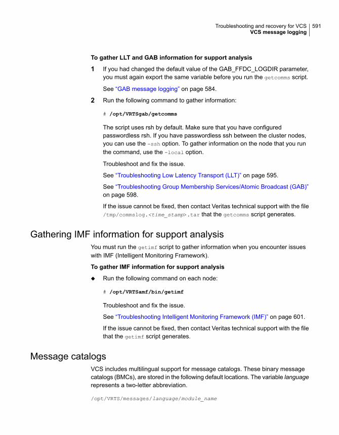
To gather LLT and GAB information for support analysis
1 If you had changed the default value of the GAB_FFDC_LOGDIR parameter,you must again export the same variable before you run the getcomms script.
See “GAB message logging” on page 584.
2 Run the following command to gather information:
# /opt/VRTSgab/getcomms
The script uses rsh by default. Make sure that you have configuredpasswordless rsh. If you have passwordless ssh between the cluster nodes,you can use the -ssh option. To gather information on the node that you runthe command, use the -local option.
Troubleshoot and fix the issue.
See “Troubleshooting Low Latency Transport (LLT)” on page 595.
See “Troubleshooting Group Membership Services/Atomic Broadcast (GAB)”on page 598.
If the issue cannot be fixed, then contact Veritas technical support with the file/tmp/commslog.<time_stamp>.tar that the getcomms script generates.
Gathering IMF information for support analysisYou must run the getimf script to gather information when you encounter issueswith IMF (Intelligent Monitoring Framework).
To gather IMF information for support analysis
◆ Run the following command on each node:
# /opt/VRTSamf/bin/getimf
Troubleshoot and fix the issue.
See “Troubleshooting Intelligent Monitoring Framework (IMF)” on page 601.
If the issue cannot be fixed, then contact Veritas technical support with the filethat the getimf script generates.
Message catalogsVCS includes multilingual support for message catalogs. These binary messagecatalogs (BMCs), are stored in the following default locations. The variable languagerepresents a two-letter abbreviation.
/opt/VRTS/messages/language/module_name
591Troubleshooting and recovery for VCSVCS message logging

The VCS command-line interface displays error and success messages inVCS-supported languages. The hamsg command displays the VCS engine logs inVCS-supported languages.
The BMCs are:
Asynchronous Monitoring Framework (AMF) messagesamf.bmc
fdsetup messagesfdsetup.bmc
GAB command-line interface messagesgab.bmc
gcoconfig messagesgcoconfig.bmc
hagetcf messageshagetcf.bmc
hagui messageshagui.bmc
haimfconfig messageshaimfconfig.bmc
hazonesetup messageshazonesetup.bmc
hazoneverify messageshazoneverify.bmc
LLT command-line interface messagesllt.bmc
uuidconfig messagesuuidconfig.bmc
Agent framework messagesVRTSvcsAgfw.bmc
VCS alert messagesVRTSvcsAlerts.bmc
VCS API messagesVRTSvcsApi.bmc
VCS cluster extender messagesVRTSvcsce.bmc
Common module messagesVRTSvcsCommon.bmc
VCS bundled agent messagesVRTSvcs<platform>Agent.bmc
VCS engine (HAD) messagesVRTSvcsHad.bmc
Heartbeat framework messagesVRTSvcsHbfw.bmc
VCS network utilities messagesVRTSvcsNetUtils.bmc
VCS enterprise agent messagesVRTSvcs<platformagent_name>.bmc
VCS trigger messagesVRTSvcsTriggers.bmc
VCS virtualization utilities messagesVRTSvcsVirtUtils.bmc
Wide-area connector process messagesVRTSvcsWac.bmc
592Troubleshooting and recovery for VCSVCS message logging

Fencing messagesvxfen*.bmc
Troubleshooting the VCS engineThis topic includes information on troubleshooting the VCS engine.
See “Preonline IP check” on page 594.
HAD diagnosticsWhen the VCS engine HAD dumps core, the core is written to the directory$VCS_DIAG/diag/had. The default value for variable $VCS_DIAG is /var/VRTSvcs/.
When HAD core dumps, review the contents of the $VCS_DIAG/diag/had directory.See the following logs for more information:
■ Operating system console log
■ Engine log
■ hashadow log
VCS runs the script /opt/VRTSvcs/bin/vcs_diag to collect diagnostic informationwhen HAD and GAB encounter heartbeat problems. The diagnostic information isstored in the $VCS_DIAG/diag/had directory.
When HAD starts, it renames the directory to had.timestamp, where timestamprepresents the time at which the directory was renamed.
HAD restarts continuouslyWhen you start HAD by using the hastart command, HAD might restartcontinuously. The system is unable to come to a RUNNING state and loses its porth membership.
Recommended action: Check the engine_A.log file for a message with theidentifier V-16-1-10125. The following message is an example:
VCS INFO V-16-1-10125 GAB timeout set to 30000 ms
The value indicates the timeout that is set for HAD to heartbeat with GAB. If systemis heavily loaded, a timeout of 30 seconds might be insufficient for HAD to heartbeatwith GAB. If required, set the timeout to an appropriate higher value.
593Troubleshooting and recovery for VCSTroubleshooting the VCS engine

DNS configuration issues cause GAB to kill HADIf HAD is periodically killed by GAB for no apparent reason, review the HAD corefiles for any DNS resolver functions (res_send(), res_query(), res_search() etc) inthe stack trace. The presence of DNS resolver functions may indicate DNSconfiguration issues.
The VCS High Availability Daemon (HAD) uses the gethostbyname() function. OnUNIX platforms, if the file /etc/nsswitch.conf has DNS in the hosts entry, a callto the gethostbyname() function may lead to calls to DNS resolver methods.
If the name servers specified in the /etc/resolve.conf are not reachable or ifthere are any DNS configuration issues, the DNS resolver methods called mayblock HAD, leading to HAD not sending heartbeats to GAB in a timely manner.
Seeding and I/O fencingWhen I/O fencing starts up, a check is done to make sure the systems that havekeys on the coordinator points are also in the GAB membership. If the gabconfig
command in /etc/gabtab allows the cluster to seed with less than the full numberof systems in the cluster, or the cluster is forced to seed with the gabconfig -x
command, it is likely that this check will not match. In this case, the fencing modulewill detect a possible split-brain condition, print an error, and HAD will not start.
It is recommended to let the cluster automatically seed when all members of thecluster can exchange heartbeat signals to each other. In this case, all systemsperform the I/O fencing key placement after they are already in the GABmembership.
Preonline IP checkYou can enable a preonline check of a failover IP address to protect against networkpartitioning. The check pings a service group's configured IP address to verify thatit is not already in use. If it is, the service group is not brought online.
A second check verifies that the system is connected to its public network andprivate network. If the system receives no response from a broadcast ping to thepublic network and a check of the private networks, it determines the system isisolated and does not bring the service group online.
To enable the preonline IP check, do one of the following:
■ If preonline trigger script is not already present, copy the preonline trigger scriptfrom the sample triggers directory into the triggers directory:
# cp /opt/VRTSvcs/bin/sample_triggers/VRTSvcs/preonline_ipc
/opt/VRTSvcs/bin/triggers/preonline
594Troubleshooting and recovery for VCSTroubleshooting the VCS engine

Change the file permissions to make it executable.
■ If preonline trigger script is already present, create a directory such as/preonline and move the existing preonline trigger as T0preonline to thatdirectory. Copy the preonline_ipc trigger as T1preonline to the same directory.
■ If you already use multiple triggers, copy the preonline_ipc trigger as TNpreonline,where TN is the next higher TNumber.
Troubleshooting Low Latency Transport (LLT)This section includes error messages associated with Low Latency Transport (LLT)and provides descriptions and the recommended action.
LLT startup script displays errorsIf more than one system on the network has the same clusterid-nodeid pair andthe same Ethernet sap/UDP port, then the LLT startup script displays error messagessimilar to the following:
LLT lltconfig ERROR V-14-2-15238 node 1 already exists
in cluster 8383 and has the address - 00:18:8B:E4:DE:27
LLT lltconfig ERROR V-14-2-15241 LLT not configured,
use -o to override this warning
LLT lltconfig ERROR V-14-2-15664 LLT could not
configure any link
LLT lltconfig ERROR V-14-2-15245 cluster id 1 is
already being used by nid 0 and has the
address - 00:04:23:AC:24:2D
LLT lltconfig ERROR V-14-2-15664 LLT could not
configure any link
Recommended action: Ensure that all systems on the network have uniqueclusterid-nodeid pair. You can use the lltdump -f device -D command to getthe list of unique clusterid-nodeid pairs connected to the network. This utility isavailable only for LLT-over-ethernet.
LLT detects cross links usageIf LLT detects more than one link of a system that is connected to the same network,then LLT logs a warning message similar to the following in the/var/adm/streams/error.date log:
595Troubleshooting and recovery for VCSTroubleshooting Low Latency Transport (LLT)

LLT WARNING V-14-1-10498 recvarpack cross links? links 0 and 2 saw
the same peer link number 1 for node 1
Recommended Action: This is an informational message. LLT supports cross links.However, if this cross links is not an intentional network setup, then make sure thatno two links from the same system go to the same network. That is, the LLT linksneed to be on separate networks.
LLT link status messagesTable 21-1 describes the LLT logs messages such as trouble, active, inactive, orexpired in the syslog for the links.
Table 21-1 LLT link status messages
Description and Recommended actionMessage
This message implies that LLT did not receive any heartbeatson the indicated link from the indicated peer node for LLTpeertrouble time. The default LLT peertrouble time is 2s forhipri links and 4s for lo-pri links.
Recommended action: If these messages sporadically appearin the syslog, you can ignore them. If these messages floodthe syslog, then perform one of the following:
■ Increase the peertrouble time to a higher value (butsignificantly lower than the peerinact value). Run thefollowing command:
lltconfig -T peertrouble:<value>for hipri linklltconfig -T peertroublelo:<value>for lopri links.
See the lltconfig(1m) manual page for details.■ Replace the LLT link.
See “Adding and removing LLT links” on page 95.
LLT INFO V-14-1-10205link 1 (link_name) node 1 in trouble
This message implies that LLT started seeing heartbeats onthis link from that node.
Recommended action: No action is required. This messageis informational.
LLT INFO V-14-1-10024link 0 (link_name) node 1 active
596Troubleshooting and recovery for VCSTroubleshooting Low Latency Transport (LLT)

Table 21-1 LLT link status messages (continued)
Description and Recommended actionMessage
This message implies that LLT did not receive any heartbeatson the indicated link from the indicated peer node for theindicated amount of time.
If the peer node has not actually gone down, check for thefollowing:
■ Check if the link has got physically disconnected from thesystem or switch.
■ Check for the link health and replace the link if necessary.
See “Adding and removing LLT links” on page 95.
LLT INFO V-14-1-10032link 1 (link_name) node 1 inactive 5sec (510)
This message implies that LLT did not receive any heartbeatson the indicated link from the indicated peer node for morethan LLT peerinact time. LLT attempts to request heartbeats(sends 5 hbreqs to the peer node) and if the peer node doesnot respond, LLT marks this link as “expired” for that peernode.
Recommended action: If the peer node has not actually gonedown, check for the following:
■ Check if the link has got physically disconnected from thesystem or switch.
■ Check for the link health and replace the link if necessary.
See “Adding and removing LLT links” on page 95.
LLT INFO V-14-1-10510 sent hbreq(NULL) on link 1 (link_name) node 1.4 more to go.LLT INFO V-14-1-10510 sent hbreq(NULL) on link 1 (link_name) node 1.3 more to go.LLT INFO V-14-1-10510 sent hbreq(NULL) on link 1 (link_name) node 1.2 more to go.LLT INFO V-14-1-10032 link 1(link_name) node 1 inactive 6 sec(510)LLT INFO V-14-1-10510 sent hbreq(NULL) on link 1 (link_name) node 1.1 more to go.LLT INFO V-14-1-10510 sent hbreq(NULL) on link 1 (link_name) node 1.0 more to go.LLT INFO V-14-1-10032 link 1(link_name) node 1 inactive 7 sec(510)LLT INFO V-14-1-10509 link 1(link_name) node 1 expired
This message is logged when LLT learns the peer node’saddress.
Recommended action: No action is required. This messageis informational.
LLT INFO V-14-1-10499 recvarpreqlink 0 for node 1 addr change from00:00:00:00:00:00 to00:18:8B:E4:DE:27
597Troubleshooting and recovery for VCSTroubleshooting Low Latency Transport (LLT)

Table 21-1 LLT link status messages (continued)
Description and Recommended actionMessage
These messages are printed when you have enabled LLT todetect faster failure of links. When a link fails or isdisconnected from a node (cable pull, switch failure, and soon), LLT on the local node detects this event and propagatesthis information to all the peer nodes over the LLT hidden link.LLT marks this link as disconnected when LLT on the localnode receives the acknowledgment from all the nodes.
On local node that detects the link failure:
LLT INFO V-14-1-10519 link 0 downLLT INFO V-14-1-10585 local link 0 downfor 1 sec
LLT INFO V-14-1-10586 send linkdown_ntfon link 1 for local link 0LLT INFO V-14-1-10590 recv linkdown_ackfrom node 1 on link 1 for local link 0LLT INFO V-14-1-10592 received ack fromall the connected nodes
On peer nodes:
LLT INFO V-14-1-10589 recvlinkdown_ntf from node 0 on link 1for peer link 0LLT INFO V-14-1-10587 send linkdown_ackto node 0 on link 1 for peer link 0
Troubleshooting Group MembershipServices/Atomic Broadcast (GAB)
This section includes error messages associated with Group MembershipServices/Atomic Broadcast (GAB) and provides descriptions and the recommendedaction.
GAB timer issuesGAB timer only wakes up a thread that does the real work. If either the operatingsystem did not get a chance to schedule the thread or the operating system did notfire the timer itself, then GAB might log a message similar to the following:
GAB INFO V-15-1-20124 timer not called for 11 seconds
Recommended Action: If this issue occurs rarely at times of high load, and doesnot cause any detrimental effects, the issue is benign. If the issue recurs, or if theissue causes repeated VCS daemon restarts or node panics, you must increasethe priority of the thread (gab_timer_pri tunable parameter).
598Troubleshooting and recovery for VCSTroubleshooting Group Membership Services/Atomic Broadcast (GAB)

See “About GAB load-time or static tunable parameters” on page 569.
If problem persists, collect the following and contact Veritas support:
■ sar or perfmgr data
■ Any VCS daemon diagnostics
■ Any panic dumps
■ commslog on all nodes
Delay in port reopenIf a GAB port was closed and reopened before LLT state cleanup action iscompleted, then GAB logs a message similar to the following:
GAB INFO V-15-1-20102 Port v: delayed reopen
Recommended Action: If this issue occurs during a GAB reconfiguration, and doesnot recur, the issue is benign. If the issue persists, collect commslog from eachnode, and contact Veritas support.
Node panics due to client process failureIf VCS daemon does not heartbeat with GAB within the configured timeout specifiedin VCS_GAB_TIMEOUT (default 30sec) environment variable, the node panicswith a message similar to the following:
GAB Port h halting node due to client process failure at 3:109
GABs attempt (five retries) to kill the VCS daemon fails if VCS daemon is stuck inthe kernel in an uninterruptible state or the system is heavily loaded that the VCSdaemon cannot die with a SIGKILL.
Recommended Action:
■ In case of performance issues, increase the value of the VCS_GAB_TIMEOUTenvironment variable to allow VCS more time to heartbeat.See “ VCS environment variables” on page 70.
■ In case of a kernel problem, configure GAB to not panic but continue to attemptkilling the VCS daemon.
Do the following:
■ Run the following command on each node:
gabconfig -k
599Troubleshooting and recovery for VCSTroubleshooting Group Membership Services/Atomic Broadcast (GAB)
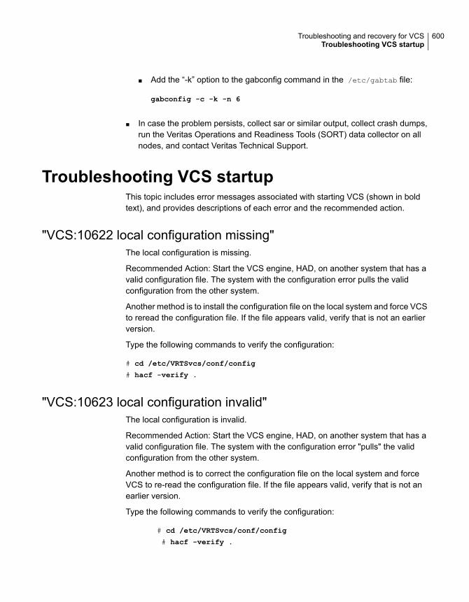
■ Add the “-k” option to the gabconfig command in the /etc/gabtab file:
gabconfig -c -k -n 6
■ In case the problem persists, collect sar or similar output, collect crash dumps,run the Veritas Operations and Readiness Tools (SORT) data collector on allnodes, and contact Veritas Technical Support.
Troubleshooting VCS startupThis topic includes error messages associated with starting VCS (shown in boldtext), and provides descriptions of each error and the recommended action.
"VCS:10622 local configuration missing"The local configuration is missing.
Recommended Action: Start the VCS engine, HAD, on another system that has avalid configuration file. The system with the configuration error pulls the validconfiguration from the other system.
Another method is to install the configuration file on the local system and force VCSto reread the configuration file. If the file appears valid, verify that is not an earlierversion.
Type the following commands to verify the configuration:
# cd /etc/VRTSvcs/conf/config
# hacf -verify .
"VCS:10623 local configuration invalid"The local configuration is invalid.
Recommended Action: Start the VCS engine, HAD, on another system that has avalid configuration file. The system with the configuration error "pulls" the validconfiguration from the other system.
Another method is to correct the configuration file on the local system and forceVCS to re-read the configuration file. If the file appears valid, verify that is not anearlier version.
Type the following commands to verify the configuration:
# cd /etc/VRTSvcs/conf/config
# hacf -verify .
600Troubleshooting and recovery for VCSTroubleshooting VCS startup

"VCS:11032 registration failed. Exiting"GAB was not registered or has become unregistered.
Recommended Action: GAB is registered by the gabconfig command in the file/etc/gabtab. Verify that the file exists and that it contains the command gabconfig
-c.
GAB can become unregistered if LLT is set up incorrectly. Verify that theconfiguration is correct in /etc/llttab. If the LLT configuration is incorrect, make theappropriate changes and reboot.
"Waiting for cluster membership."This indicates that GAB may not be seeded. If this is the case, the commandgabconfig -a does not show any members, and the following messages mayappear on the console or in the event log.
GAB: Port a registration waiting for seed port membership
GAB: Port h registration waiting for seed port membership
Troubleshooting IntelligentMonitoring Framework(IMF)
Review the following logs to isolate and troubleshoot Intelligent MonitoringFramework (IMF) related issues:
■ System console log for the given operating system
■ VCS engine Log : /var/VRTSvcs/log/engine_A.log
■ Agent specific log : /var/VRTSvcs/log/<agentname>_A.log
■ AMF in-memory trace buffer : View the contents using the amfconfig -p dbglog
command
See “Enabling debug logs for IMF” on page 586.
See “Gathering IMF information for support analysis” on page 591.
Table 21-2 lists the most common issues for intelligent resource monitoring andprovides instructions to troubleshoot and fix the issues.
601Troubleshooting and recovery for VCSTroubleshooting Intelligent Monitoring Framework (IMF)

Table 21-2 IMF-related issues and recommended actions
Description and recommended actionIssue
If the system is busy even after intelligent resource monitoring is enabled, troubleshoot asfollows:
■ Check the agent log file to see whether the imf_init agent function has failed.
If the imf_init agent function has failed, then do the following:■ Make sure that the AMF_START environment variable value is set to 1.
See “Environment variables to start and stop VCS modules” on page 75.■ Make sure that the AMF module is loaded.
See “Administering the AMF kernel driver” on page 99.■ Make sure that the IMF attribute values are set correctly for the following attribute keys:
■ The value of the Mode key of the IMF attribute must be set to 1, 2, or 3.■ The value of the MonitorFreq key of the IMF attribute must be be set to either 0 or a
value greater than 0.For example, the value of the MonitorFreq key can be set to 0 for the Process agent.Refer to the appropriate agent documentation for configuration recommendationscorresponding to the IMF-aware agent.Note that the IMF attribute can be overridden. So, if the attribute is set for individualresource, then check the value for individual resource.
See “Resource type attributes” on page 664.■ Verify that the resources are registered with the AMF driver. Check the amfstat
command output.■ Check the LevelTwoMonitorFreq attribute settings for the agent. For example, Process
agent must have this attribute value set to 0.Refer to the appropriate agent documentation for configuration recommendationscorresponding to the IMF-aware agent.
Intelligent resourcemonitoring has notreduced systemutilization
The actual intelligent monitoring for a resource starts only after a steady state is achieved.So, it takes some time before you can see positive performance effect after you enable IMF.This behavior is expected.
For more information on when a steady state is reached, see the following topic:
See “How intelligent resource monitoring works” on page 39.
Enabling the agent'sintelligent monitoringdoes not provideimmediate performanceresults
602Troubleshooting and recovery for VCSTroubleshooting Intelligent Monitoring Framework (IMF)
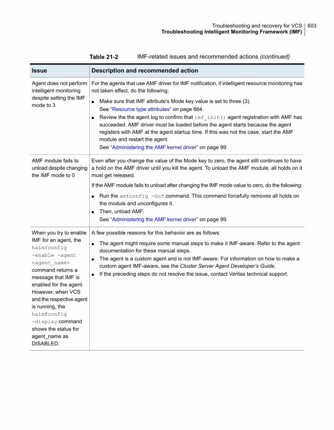
Table 21-2 IMF-related issues and recommended actions (continued)
Description and recommended actionIssue
For the agents that use AMF driver for IMF notification, if intelligent resource monitoring hasnot taken effect, do the following:
■ Make sure that IMF attribute's Mode key value is set to three (3).See “Resource type attributes” on page 664.
■ Review the the agent log to confirm that imf_init() agent registration with AMF hassucceeded. AMF driver must be loaded before the agent starts because the agentregisters with AMF at the agent startup time. If this was not the case, start the AMFmodule and restart the agent.See “Administering the AMF kernel driver” on page 99.
Agent does not performintelligent monitoringdespite setting the IMFmode to 3
Even after you change the value of the Mode key to zero, the agent still continues to havea hold on the AMF driver until you kill the agent. To unload the AMF module, all holds on itmust get released.
If the AMF module fails to unload after changing the IMF mode value to zero, do the following:
■ Run the amfconfig -Uof command. This command forcefully removes all holds onthe module and unconfigures it.
■ Then, unload AMF.See “Administering the AMF kernel driver” on page 99.
AMF module fails tounload despite changingthe IMF mode to 0
A few possible reasons for this behavior are as follows:
■ The agent might require some manual steps to make it IMF-aware. Refer to the agentdocumentation for these manual steps.
■ The agent is a custom agent and is not IMF-aware. For information on how to make acustom agent IMF-aware, see the Cluster Server Agent Developer’s Guide.
■ If the preceding steps do not resolve the issue, contact Veritas technical support.
When you try to enableIMF for an agent, thehaimfconfig-enable -agent<agent_name>command returns amessage that IMF isenabled for the agent.However, when VCSand the respective agentis running, thehaimfconfig-display commandshows the status foragent_name asDISABLED.
603Troubleshooting and recovery for VCSTroubleshooting Intelligent Monitoring Framework (IMF)

Troubleshooting service groupsThis topic cites the most common problems associated with bringing service groupsonline and taking them offline. Bold text provides a description of the problem.Recommended action is also included, where applicable.
VCS does not automatically start service groupVCS does not automatically start a failover service group if the VCS engine (HAD)in the cluster was restarted by the hashadow process.
This behavior prevents service groups from coming online automatically due toevents such as GAB killing HAD because to high load, or HAD committing suicideto rectify unexpected error conditions.
System is not in RUNNING stateRecommended Action: Type hasys -display system to check the system status.When the system is not in running state, we may start VCS if there are no issuesfound.
Service group not configured to run on the systemThe SystemList attribute of the group may not contain the name of the system.
Recommended Action: Use the output of the command hagrp -display
service_group to verify the system name.
Service group not configured to autostartIf the service group is not starting automatically on the system, the group may notbe configured to AutoStart, or may not be configured to AutoStart on that particularsystem.
Recommended Action: Use the output of the command hagrp -display
service_group AutoStartList node_list to verify the values of the AutoStartand AutoStartList attributes.
Service group is frozenRecommended Action: Use the output of the command hagrp -display
service_group to verify the value of the Frozen and TFrozen attributes. Use thecommand hagrp -unfreeze to unfreeze the group. Note that VCS will not take afrozen service group offline.
604Troubleshooting and recovery for VCSTroubleshooting service groups

Failover service group is online on another systemThe group is a failover group and is online or partially online on another system.
Recommended Action: Use the output of the command hagrp -display
service_group to verify the value of the State attribute. Use the command hagrp
-offline to offline the group on another system.
A critical resource faultedOutput of the command hagrp -display service_group indicates that the servicegroup has faulted.
Recommended Action: Use the command hares -clear to clear the fault.
Service group autodisabledWhen VCS does not know the status of a service group on a particular system, itautodisables the service group on that system. Autodisabling occurs under thefollowing conditions:
■ When the VCS engine, HAD, is not running on the system.Under these conditions, all service groups that include the system in theirSystemList attribute are autodisabled. This does not apply to systems that arepowered off.
■ When all resources within the service group are not probed on the system.
Recommended Action: Use the output of the command hagrp -display
service_group to verify the value of the AutoDisabled attribute.
Warning: To bring a group online manually after VCS has autodisabled the group,make sure that the group is not fully or partially active on any system that has theAutoDisabled attribute set to 1 by VCS. Specifically, verify that all resources thatmay be corrupted by being active on multiple systems are brought down on thedesignated systems. Then, clear the AutoDisabled attribute for each system: #hagrp -autoenable service_group -sys system
Service group is waiting for the resource to be brought online/takenoffline
Recommended Action: Review the IState attribute of all resources in the servicegroup to locate which resource is waiting to go online (or which is waiting to betaken offline). Use the hastatus command to help identify the resource. See the
605Troubleshooting and recovery for VCSTroubleshooting service groups

engine and agent logs in /var/VRTSvcs/log for information on why the resource isunable to be brought online or be taken offline.
To clear this state, make sure all resources waiting to go online/offline do not bringthemselves online/offline. Use the hagrp -flush command or the hagrp -flush
-force command to clear the internal state of VCS. You can then bring the servicegroup online or take it offline on another system.
For more information on the hagrp -flush and hagrp -flush -force commands.
Warning: Exercise caution when you use the -force option. It can lead to situationswhere a resource status is unintentionally returned as FAULTED. In the time intervalthat a resource transitions from ‘waiting to go offline’ to ‘not waiting’, if the agenthas not completed the offline agent function, the agent may return the state of theresource as OFFLINE. VCS considers such unexpected offline of the resource asFAULT and starts recovery action that was not intended.
Service group is waiting for a dependency to be met.Recommended Action: To see which dependencies have not been met, type hagrp
-dep service_group to view service group dependencies, or hares -dep resource
to view resource dependencies.
Service group not fully probed.This occurs if the agent processes have not monitored each resource in the servicegroup. When the VCS engine, HAD, starts, it immediately "probes" to find the initialstate of all of resources. (It cannot probe if the agent is not returning a value.) Aservice group must be probed on all systems included in the SystemList attributebefore VCS attempts to bring the group online as part of AutoStart. This ensuresthat even if the service group was online prior to VCS being brought up, VCS willnot inadvertently bring the service group online on another system.
Recommended Action: Use the output of hagrp -display service_group to seethe value of the ProbesPending attribute for the system's service group. The valueof the ProbesPending attribute corresponds to the number of resources which arenot probed, and it should be zero when all resources are probed. To determinewhich resources are not probed, verify the local "Probed" attribute for each resourceon the specified system. Zero means waiting for probe result, 1 means probed, and2 means VCS not booted. See the engine and agent logs for information.
606Troubleshooting and recovery for VCSTroubleshooting service groups

Service group does not fail over to the forecasted systemThis behaviour is expected when other events occur between the time the hagrp
–forecast command was executed and the time when the service group or systemactually fail over or switch over. VCS might select a system which is different thanone mentioned in the hagrp –forecast command.
VCS logs detailed messages in the engine log, including the reason for selectinga specific node as a target node over other possible target nodes.
Service group does not fail over to the BiggestAvailable system evenif FailOverPolicy is set to BiggestAvailable
Sometimes, a service group might not fail over to the biggest available system evenwhen FailOverPolicy is set to BiggestAvailable.
To troubleshoot this issue, check the engine log located in/var/VRTSvcs/log/engine_A.log to find out the reasons for not failing over to thebiggest available system. This may be due to the following reasons:
■ If , one or more of the systems in the service group’s SystemList did not haveforecasted available capacity, you see the following message in the engine log:One of the systems in SystemList of group group_name, systemsystem_name does not have forecasted available capacity updated
■ If the hautil –sys command does not list forecasted available capacity for thesystems, you see the following message in the engine log:Failed to forecast due to insufficient dataThis message is displayed due to insufficient recent data to be used forforecasting the available capacity.The default value for the MeterInterval key of the cluster attribute MeterControlis 120 seconds. There will be enough recent data available for forecasting after3 metering intervals (6 minutes) from time the VCS engine was started on thesystem. After this, the forecasted values are updated every ForecastCycle *MeterInterval seconds. The ForecastCycle and MeterInterval values are specifiedin the cluster attribute MeterControl.
■ If one or more of the systems in the service group’s SystemList have staleforecasted available capacity, you can see the following message in the enginelog:System system_name has not updated forecasted available capacity sincelast 2 forecast cyclesThis issue is caused when the HostMonitor agent stops functioning. Check ifHostMonitor agent process is running by issuing one of the following commandson the system which has stale forecasted values:
607Troubleshooting and recovery for VCSTroubleshooting service groups

■ # ps –aef|grep HostMonitor
■ # haagent -display HostMonitor
If HostMonitor agent is not running, you can start it by issuing the followingcommand:
# hagent -start HostMonitor -sys system_name
Even if HostMonitor agent is running and you see the above message in theengine log, it means that the HostMonitor agent is not able to forecast, andit will log error messages in the HostMonitor_A.log file in the/var/VRTSvcs/log/ directory.
Restoring metering database from backup taken by VCSWhen VCS detects that the metering database has been corrupted or has beenaccidently deleted outside VCS, it creates a backup of the database. The dataavailable in memory is backed up and a message is logged, and administrativeintervention is required to restore the database and reinstate metering and forecast.
The following log message will appear in the engine log:
The backup of metering database from in-memory data is created and
saved in <path for metering database backup>. Administrative
intervention required to use the backup database.
To restore the database for metering and forecast functionality
1 Stop the HostMonitor agent using the following command:
# /opt/VRTSvcs/bin/haagent -stop HostMonitor -force -sys system name
2 Delete the database if it exists.
# rm /var/VRTSvcs/stats/.vcs_host_stats.data \
/var/VRTSvcs/stats/.vcs_host_stats.index
3 Restore metering database from the backup.
# cp /var/VRTSvcs/stats/.vcs_host_stats_bkup.data \
/var/VRTSvcs/stats/.vcs_host_stats.data
# cp /var/VRTSvcs/stats/.vcs_host_stats_bkup.index \
/var/VRTSvcs/stats/.vcs_host_stats.index
608Troubleshooting and recovery for VCSTroubleshooting service groups

4 Setup the database.
# /opt/VRTSvcs/bin/vcsstatlog --setprop \
/var/VRTSvcs/stats/.vcs_host_stats rate 120
# /opt/VRTSvcs/bin/vcsstatlog --setprop \
/var/VRTSvcs/stats/.vcs_host_stats compressto \
/var/VRTSvcs/stats/.vcs_host_stats_daily
# /opt/VRTSvcs/bin/vcsstatlog --setprop \
/var/VRTSvcs/stats/.vcs_host_stats compressmode avg
# /opt/VRTSvcs/bin/vcsstatlog --setprop \
/var/VRTSvcs/stats/.vcs_host_stats compressfreq 24h
5 Start the HostMonitor agent.
# /opt/VRTSvcs/bin/haagent -start HostMonitor -sys system name
Initialization of metering database failsThe metering database can fail to initialize if there is an existing corrupt database.In this case, VCS cannot open and initialize the database.
The following log message will appear in the engine log:
Initialization of database to save metered data failed and will not
be able to get forecast. Error corrupt statlog database, error
code=19, errno=0
To restore the metering and forecast functionality,
1 Stop the HostMonitor agent using the following command
# /opt/VRTSvcs/bin/haagent -stop HostMonitor -force -sys system name
2 Delete the metering database.
# rm /var/VRTSvcs/stats/.vcs_host_stats.data \
/var/VRTSvcs/stats/.vcs_host_stats.index
3 Start the HostMonitor agent.
# /opt/VRTSvcs/bin/haagent -start HostMonitor -sys system name
609Troubleshooting and recovery for VCSTroubleshooting service groups

Error message appears during service group failover or switchDuring a service group failover or switch, if the system tries to unreserve more thanthe reserved capacity, the following error message appears:
VCS ERROR V-16-1-56034 ReservedCapacity for attribute dropped below zero for
system sys1 when unreserving for group service_group; setting to zero.
This error message appears only if the service group's load requirements changeduring the transition period.
Recommended Action: No action is required. You can ignore this message.
Troubleshooting resourcesThis topic cites the most common problems associated with bringing resourcesonline and taking them offline. Bold text provides a description of the problem.Recommended action is also included, where applicable.
Service group brought online due to failoverVCS attempts to bring resources online that were already online on the failed system,or were in the process of going online. Each parent resource must wait for its childresources to be brought online before starting.
Recommended Action: Verify that the child resources are online.
Waiting for service group statesThe state of the service group prevents VCS from bringing the resource online.
Recommended Action: Review the state of the service group.
Waiting for child resourcesOne or more child resources of parent resource are offline.
Recommended Action: Bring the child resources online first.
Waiting for parent resourcesOne or more parent resources are online.
Recommended Action: Take the parent resources offline first.
See “Troubleshooting resources” on page 610.
610Troubleshooting and recovery for VCSTroubleshooting resources

Waiting for resource to respondThe resource is waiting to come online or go offline, as indicated. VCS directed theagent to run an online entry point for the resource.
Recommended Action: Verify the resource's IState attribute. See the engine andagent logs in /var/VRTSvcs/engine_A.log and /var/VRTSvcs/agent_A.log forinformation on why the resource cannot be brought online.
Agent not runningThe resource's agent process is not running.
Recommended Action: Use hastatus -summary to see if the agent is listed asfaulted. Restart the agent:
# haagent -start resource_type -sys system
Invalid agent argument list.The scripts are receiving incorrect arguments.
Recommended Action: Verify that the arguments to the scripts are correct. Use theoutput of hares -display resource to see the value of the ArgListValues attribute.If the ArgList attribute was dynamically changed, stop the agent and restart it.
To stop the agent:
◆ # haagent -stop resource_type -sys system
To restart the agent
◆ # haagent -start resource_type -sys system
The Monitor entry point of the disk group agent returns ONLINE evenif the disk group is disabled
This is expected agent behavior. VCS assumes that data is being read from orwritten to the volumes and does not declare the resource as offline. This preventspotential data corruption that could be caused by the disk group being imported ontwo hosts.
You can deport a disabled disk group when all I/O operations are completed orwhen all volumes are closed. You can then reimport the disk group to the samesystem. Reimporting a disabled disk group may require a system reboot.
611Troubleshooting and recovery for VCSTroubleshooting resources

Note: A disk group is disabled if data including the kernel log, configuration copies,or headers in the private region of a significant number of disks is invalid orinaccessible. Volumes can perform read-write operations if no changes are requiredto the private regions of the disks.
Troubleshooting sitesThe following sections discuss troubleshooting the sites. Bold text provides adescription of the problem. Recommended action is also included, where applicable.
Online propagate operation was initiated but service group failed tobe online
Recommended Action: Check the State and PolicyIntention attributes for the parentand child service groups using the command:
<hagrp -display -attribute State PolicyIntention -all>
And check for errors in the engine log.
VCS panics nodes in the preferred site during a network-splitRecommended Action:
■ Check the node weights using the command <vxfenconfig -a>.Nodes in the high preference site should have higher weight than nodes in themedium or low preference sites.
■ If the node weights are not set, then check the cluster attributes UseFence andPreferredFencingPolicy.
■ Check the engine log for errors.
■ If the node weights are correct, then check the fencing logs for more details.
Configuring of stretch site failsRecommended Action:
■ For Campus Cluster, in a non-CVM configuration, check if DiskGroup is importedat least once on all nodes.Disk group should be listed in server-> <hostname> -> Disk Groups, and importedon one node and also should be in the deported state on other nodes of cluster.
612Troubleshooting and recovery for VCSTroubleshooting sites

■ If Disk Group is not appearing in the server-> <Hostname> -> Disk Groups, thenright click on <Hostname> and run Rescan Disks.
■ For Campus cluster, tag all enclosures whose disks are part of Disk Groupsused for campus cluster setup
Renaming a SiteRecommended Action: For renaming the site, re-run the Stretch ClusterConfiguration flow by changing the Site names
Troubleshooting I/O fencingThe following sections discuss troubleshooting the I/O fencing problems. Reviewthe symptoms and recommended solutions.
Node is unable to join cluster while another node is being ejectedA cluster that is currently fencing out (ejecting) a node from the cluster prevents anew node from joining the cluster until the fencing operation is completed. Thefollowing are example messages that appear on the console for the new node:
...VxFEN ERROR V-11-1-25 ... Unable to join running cluster
since cluster is currently fencing
a node out of the cluster.
If you see these messages when the new node is booting, the vxfen startup scripton the node makes up to five attempts to join the cluster.
To manually join the node to the cluster when I/O fencing attempts fail
◆ If the vxfen script fails in the attempts to allow the node to join the cluster,restart vxfen driver with the command:
# /etc/init.d/vxfen.rc stop
# /etc/init.d/vxfen.rc start
If the command fails, restart the new node.
The vxfentsthdw utility fails when SCSI TEST UNIT READY commandfails
While running the vxfentsthdw utility, you may see a message that resembles asfollows:
613Troubleshooting and recovery for VCSTroubleshooting I/O fencing

Issuing SCSI TEST UNIT READY to disk reserved by other node
FAILED.
Contact the storage provider to have the hardware configuration
fixed.
The disk array does not support returning success for a SCSI TEST UNIT READY
command when another host has the disk reserved using SCSI-3 persistentreservations. This happens with the Hitachi Data Systems 99XX arrays if bit 186of the system mode option is not enabled.
Manually removing existing keys from SCSI-3 disksReview the following procedure to remove specific registration and reservation keyscreated by another node from a disk.
See “About the vxfenadm utility” on page 274.
Note: If you want to clear all the pre-existing keys, use the vxfenclearpre utility.
See “About the vxfenclearpre utility” on page 279.
To remove the registration and reservation keys from disk
1 Create a file to contain the access names of the disks:
# vi /tmp/disklist
For example:
/dev/rhdisk74
2 Read the existing keys:
# vxfenadm -s all -f /tmp/disklist
The output from this command displays the key:
Device Name: /dev/rhdisk74
Total Number Of Keys: 1
key[0]:
[Numeric Format]: 86,70,66,69,65,68,48,50
[Character Format]: VFBEAD02
[Node Format]: Cluster ID: 48813 Node ID: 2
Node Name: unknown
614Troubleshooting and recovery for VCSTroubleshooting I/O fencing

3 If you know on which node the key (say A1) was created, log in to that nodeand enter the following command:
# vxfenadm -x -kA1 -f /tmp/disklist
The key A1 is removed.
4 If you do not know on which node the key was created, follow 5 through 7 toremove the key.
5 Register a second key “A2” temporarily with the disk:
# vxfenadm -m -k A2 -f /tmp/disklist
Registration completed for disk path /dev/rhdisk74
6 Remove the first key from the disk by preempting it with the second key:
# vxfenadm -p -kA2 -f /tmp/disklist -vA1
key: A2------ prempted the key: A1------ on disk
/dev/rhdisk74
7 Remove the temporary key registered in 5.
# vxfenadm -x -kA2 -f /tmp/disklist
Deleted the key : [A2------] from device /dev/rhdisk74
No registration keys exist for the disk.
System panics to prevent potential data corruptionWhen a node experiences a split-brain condition and is ejected from the cluster, itpanics and displays the following console message:
VXFEN:vxfen_plat_panic: Local cluster node ejected from cluster to
prevent potential data corruption.
A node experiences the split-brain condition when it loses the heartbeat with itspeer nodes due to failure of all private interconnects or node hang. Review thebehavior of I/O fencing under different scenarios and the corrective measures tobe taken.
See “How I/O fencing works in different event scenarios” on page 251.
615Troubleshooting and recovery for VCSTroubleshooting I/O fencing
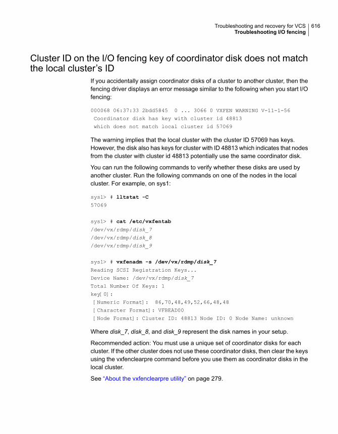
Cluster ID on the I/O fencing key of coordinator disk does not matchthe local cluster’s ID
If you accidentally assign coordinator disks of a cluster to another cluster, then thefencing driver displays an error message similar to the following when you start I/Ofencing:
000068 06:37:33 2bdd5845 0 ... 3066 0 VXFEN WARNING V-11-1-56
Coordinator disk has key with cluster id 48813
which does not match local cluster id 57069
The warning implies that the local cluster with the cluster ID 57069 has keys.However, the disk also has keys for cluster with ID 48813 which indicates that nodesfrom the cluster with cluster id 48813 potentially use the same coordinator disk.
You can run the following commands to verify whether these disks are used byanother cluster. Run the following commands on one of the nodes in the localcluster. For example, on sys1:
sys1> # lltstat -C
57069
sys1> # cat /etc/vxfentab
/dev/vx/rdmp/disk_7
/dev/vx/rdmp/disk_8
/dev/vx/rdmp/disk_9
sys1> # vxfenadm -s /dev/vx/rdmp/disk_7
Reading SCSI Registration Keys...
Device Name: /dev/vx/rdmp/disk_7
Total Number Of Keys: 1
key[0]:
[Numeric Format]: 86,70,48,49,52,66,48,48
[Character Format]: VFBEAD00
[Node Format]: Cluster ID: 48813 Node ID: 0 Node Name: unknown
Where disk_7, disk_8, and disk_9 represent the disk names in your setup.
Recommended action: You must use a unique set of coordinator disks for eachcluster. If the other cluster does not use these coordinator disks, then clear the keysusing the vxfenclearpre command before you use them as coordinator disks in thelocal cluster.
See “About the vxfenclearpre utility” on page 279.
616Troubleshooting and recovery for VCSTroubleshooting I/O fencing

Fencing startup reports preexisting split-brainThe vxfen driver functions to prevent an ejected node from rejoining the clusterafter the failure of the private network links and before the private network links arerepaired.
For example, suppose the cluster of system 1 and system 2 is functioning normallywhen the private network links are broken. Also suppose system 1 is the ejectedsystem. When system 1 restarts before the private network links are restored, itsmembership configuration does not show system 2; however, when it attempts toregister with the coordinator disks, it discovers system 2 is registered with them.Given this conflicting information about system 2, system 1 does not join the clusterand returns an error from vxfenconfig that resembles:
vxfenconfig: ERROR: There exists the potential for a preexisting
split-brain. The coordinator disks list no nodes which are in
the current membership. However, they also list nodes which are
not in the current membership.
I/O Fencing Disabled!
Also, the following information is displayed on the console:
<date> <system name> vxfen: WARNING: Potentially a preexisting
<date> <system name> split-brain.
<date> <system name> Dropping out of cluster.
<date> <system name> Refer to user documentation for steps
<date> <system name> required to clear preexisting split-brain.
<date> <system name>
<date> <system name> I/O Fencing DISABLED!
<date> <system name>
<date> <system name> gab: GAB:20032: Port b closed
However, the same error can occur when the private network links are working andboth systems go down, system 1 restarts, and system 2 fails to come back up. Fromthe view of the cluster from system 1, system 2 may still have the registrations onthe coordination points.
Assume the following situations to understand preexisting split-brain in server-basedfencing:
■ There are three CP servers acting as coordination points. One of the three CPservers then becomes inaccessible. While in this state, one client node leavesthe cluster, whose registration cannot be removed from the inaccessible CPserver. When the inaccessible CP server restarts, it has a stale registration fromthe node which left the VCS cluster. In this case, no new nodes can join thecluster. Each node that attempts to join the cluster gets a list of registrations
617Troubleshooting and recovery for VCSTroubleshooting I/O fencing

from the CP server. One CP server includes an extra registration (of the nodewhich left earlier). This makes the joiner node conclude that there exists apreexisting split-brain between the joiner node and the node which is representedby the stale registration.
■ All the client nodes have crashed simultaneously, due to which fencing keysare not cleared from the CP servers. Consequently, when the nodes restart, thevxfen configuration fails reporting preexisting split brain.
These situations are similar to that of preexisting split-brain with coordinator disks,where you can solve the problem running the vxfenclearpre command. A similarsolution is required in server-based fencing using the cpsadm command.
See “Clearing preexisting split-brain condition” on page 618.
Clearing preexisting split-brain conditionReview the information on how the VxFEN driver checks for preexisting split-braincondition.
See “Fencing startup reports preexisting split-brain” on page 617.
See “About the vxfenclearpre utility” on page 279.
Table 21-3 describes how to resolve a preexisting split-brain condition dependingon the scenario you have encountered:
Table 21-3 Recommened solution to clear pre-existing split-brain condition
SolutionScenario
1 Determine if system1 is up or not.
2 If system 1 is up and running, shut it down and repair the private network links to removethe split-brain condition.
3 Restart system 1.
Actual potentialsplit-braincondition—system 2 isup and system 1 isejected
618Troubleshooting and recovery for VCSTroubleshooting I/O fencing

Table 21-3 Recommened solution to clear pre-existing split-brain condition(continued)
SolutionScenario
1 Physically verify that system 2 is down.
Verify the systems currently registered with the coordination points.
Use the following command for coordinator disks:
# vxfenadm -s all -f /etc/vxfentab
The output of this command identifies the keys registered with the coordinator disks.
2 Clear the keys on the coordinator disks as well as the data disks in all shared diskgroups using the vxfenclearpre command. The command removes SCSI-3registrations and reservations.
See “About the vxfenclearpre utility” on page 279.
3 Make any necessary repairs to system 2.
4 Restart system 2.
Apparent potentialsplit-braincondition—system 2 isdown and system 1 isejected
(Disk-based fencing isconfigured)
1 Physically verify that system 2 is down.
Verify the systems currently registered with the coordination points.
Use the following command for CP servers:
# cpsadm -s cp_server -a list_membership-c cluster_name
where cp_server is the virtual IP address or virtual hostname on which CP server isconfigured, and cluster_name is the VCS name for the VCS cluster (application cluster).
The command lists the systems registered with the CP server.
2 Clear the keys on the coordinator disks as well as the data disks in all shared diskgroups using the vxfenclearpre command. The command removes SCSI-3registrations and reservations.
After removing all stale registrations, the joiner node will be able to join the cluster.
3 Make any necessary repairs to system 2.
4 Restart system 2.
Apparent potentialsplit-braincondition—system 2 isdown and system 1 isejected
(Server-based fencing isconfigured)
Registered keys are lost on the coordinator disksIf the coordinator disks lose the keys that are registered, the cluster might panicwhen a cluster reconfiguration occurs.
619Troubleshooting and recovery for VCSTroubleshooting I/O fencing

To refresh the missing keys
◆ Use the vxfenswap utility to replace the coordinator disks with the same disks.The vxfenswap utility registers the missing keys during the disk replacement.
See “Refreshing lost keys on coordinator disks” on page 293.
Replacing defective disks when the cluster is offlineIf the disk in the coordinator disk group becomes defective or inoperable and youwant to switch to a new diskgroup in a cluster that is offline, then perform thefollowing procedure.
In a cluster that is online, you can replace the disks using the vxfenswap utility.
See “About the vxfenswap utility” on page 282.
Review the following information to replace coordinator disk in the coordinator diskgroup, or to destroy a coordinator disk group.
Note the following about the procedure:
■ When you add a disk, add the disk to the disk group vxfencoorddg and retestthe group for support of SCSI-3 persistent reservations.
■ You can destroy the coordinator disk group such that no registration keys remainon the disks. The disks can then be used elsewhere.
To replace a disk in the coordinator disk group when the cluster is offline
1 Log in as superuser on one of the cluster nodes.
2 If VCS is running, shut it down:
# hastop -all
Make sure that the port h is closed on all the nodes. Run the following commandto verify that the port h is closed:
# gabconfig -a
3 Stop I/O fencing on each node:
# /etc/init.d/vxfen.rc stop
This removes any registration keys on the disks.
620Troubleshooting and recovery for VCSTroubleshooting I/O fencing

4 Import the coordinator disk group. The file /etc/vxfendg includes the name ofthe disk group (typically, vxfencoorddg) that contains the coordinator disks, souse the command:
# vxdg -tfC import ‘cat /etc/vxfendg‘
where:
-t specifies that the disk group is imported only until the node restarts.
-f specifies that the import is to be done forcibly, which is necessary if one ormore disks is not accessible.
-C specifies that any import locks are removed.
5 To remove disks from the disk group, use the VxVM disk administrator utility,vxdiskadm.
You may also destroy the existing coordinator disk group. For example:
■ Verify whether the coordinator attribute is set to on.
# vxdg list vxfencoorddg | grep flags: | grep coordinator
■ Destroy the coordinator disk group.
# vxdg -o coordinator destroy vxfencoorddg
6 Add the new disk to the node and initialize it as a VxVM disk.
Then, add the new disk to the vxfencoorddg disk group:
■ If you destroyed the disk group in step 5, then create the disk group againand add the new disk to it.See the Cluster Server Installation Guide for detailed instructions.
■ If the diskgroup already exists, then add the new disk to it.
# vxdg -g vxfencoorddg -o coordinator adddisk disk_name
7 Test the recreated disk group for SCSI-3 persistent reservations compliance.
See “Testing the coordinator disk group using the -c option of vxfentsthdw”on page 268.
8 After replacing disks in a coordinator disk group, deport the disk group:
# vxdg deport ‘cat /etc/vxfendg‘
621Troubleshooting and recovery for VCSTroubleshooting I/O fencing

9 On each node, start the I/O fencing driver:
# /etc/init.d/vxfen.rc start
10 Verify that the I/O fencing module has started and is enabled.
# gabconfig -a
Make sure that port b membership exists in the output for all nodes in thecluster.
# vxfenadm -d
Make sure that I/O fencing mode is not disabled in the output.
11 If necessary, restart VCS on each node:
# hastart
The vxfenswap utility exits if rcp or scp commands are not functionalThe vxfenswap utility displays an error message if rcp or scp commands are notfunctional.
To recover the vxfenswap utility fault
◆ Verify whether the rcp or scp functions properly.
Make sure that you do not use echo or cat to print messages in the .bashrcfile for the nodes.
If the vxfenswap operation is unsuccessful, use the vxfenswap –a cancel
command if required to roll back any changes that the utility made.
See “About the vxfenswap utility” on page 282.
Troubleshooting CP serverAll CP server operations and messages are logged in the /var/VRTScps/log directoryin a detailed and easy to read format. The entries are sorted by date and time. Thelogs can be used for troubleshooting purposes or to review for any possible securityissue on the system that hosts the CP server.
The following files contain logs and text files that may be useful in understandingand troubleshooting a CP server:
■ /var/VRTScps/log/cpserver_[ABC].log
■ /var/VRTSvcs/log/vcsauthserver.log (Security related)
622Troubleshooting and recovery for VCSTroubleshooting I/O fencing

■ If the vxcpserv process fails on the CP server, then review the followingdiagnostic files:
■ /var/VRTScps/diag/FFDC_CPS_pid_vxcpserv.log
■ /var/VRTScps/diag/stack_pid_vxcpserv.txt
Note: If the vxcpserv process fails on the CP server, these files are present inaddition to a core file. VCS restarts vxcpserv process automatically in suchsituations.
The file /var/VRTSvcs/log/vxfen/vxfend_[ABC].log contains logs that may be usefulin understanding and troubleshooting fencing-related issues on a VCS cluster (clientcluster) node.
See “Troubleshooting issues related to the CP server service group” on page 623.
See “Checking the connectivity of CP server” on page 623.
See “Issues during fencing startup on VCS cluster nodes set up for server-basedfencing” on page 624.
See “Issues during online migration of coordination points” on page 625.
Troubleshooting issues related to the CP server servicegroupIf you cannot bring up the CPSSG service group after the CP server configuration,perform the following steps:
■ Verify that the CPSSG service group and its resources are valid and properlyconfigured in the VCS configuration.
■ Check the VCS engine log (/var/VRTSvcs/log/engine_[ABC].log) to see ifany of the CPSSG service group resources are FAULTED.
■ Review the sample dependency graphs to make sure the required resourcesare configured correctly.See “About the CP server service group” on page 239.
Checking the connectivity of CP serverYou can test the connectivity of CP server using the cpsadm command.
You must have set the environment variables CPS_USERNAME andCPS_DOMAINTYPE to run the cpsadm command on the VCS cluster (client cluster)nodes.
623Troubleshooting and recovery for VCSTroubleshooting I/O fencing

To check the connectivity of CP server
◆ Run the following command to check whether a CP server is up and runningat a process level:
# cpsadm -s cp_server -a ping_cps
where cp_server is the virtual IP address or virtual hostname on which the CPserver is listening.
Troubleshooting server-based fencing on the VCS cluster nodesThe file /var/VRTSvcs/log/vxfen/vxfend_[ABC].log contains logs files that may beuseful in understanding and troubleshooting fencing-related issues on a VCS cluster(application cluster) node.
Issues during fencing startup on VCS cluster nodes setup for server-based fencingTable 21-4 Fencing startup issues on VCS cluster (client cluster) nodes
Description and resolutionIssue
If you receive a connection error message after issuing the cpsadm command on the VCScluster, perform the following actions:
■ Ensure that the CP server is reachable from all the VCS cluster nodes.■ Check the /etc/vxfenmode file and ensure that the VCS cluster nodes use the correct
CP server virtual IP or virtual hostname and the correct port number.■ For HTTPS communication, ensure that the virtual IP and ports listed for the server can
listen to HTTPS requests.
cpsadm command onthe VCS cluster givesconnection error
Authorization failure occurs when the nodes on the client clusters and or users are not addedin the CP server configuration. Therefore, fencing on the VCS cluster (client cluster) nodeis not allowed to access the CP server and register itself on the CP server. Fencing fails tocome up if it fails to register with a majority of the coordination points.
To resolve this issue, add the client cluster node and user in the CP server configurationand restart fencing.
Authorization failure
624Troubleshooting and recovery for VCSTroubleshooting I/O fencing

Table 21-4 Fencing startup issues on VCS cluster (client cluster) nodes(continued)
Description and resolutionIssue
If you had configured secure communication between the CP server and the VCS cluster(client cluster) nodes, authentication failure can occur due to the following causes:
■ The client cluster requires its own private key, a signed certificate, and a CertificationAuthority's (CA) certificate to establish secure communication with the CP server. If anyof the files are missing or corrupt, communication fails.
■ If the client cluster certificate does not correspond to the client's private key,communication fails.
■ If the CP server and client cluster do not have a common CA in their certificate chain oftrust, then communication fails.See “About secure communication between the VCS cluster and CP server” on page 241.
Authentication failure
Issues during online migration of coordination pointsDuring online migration of coordination points using the vxfenswap utility, theoperation is automatically rolled back if a failure is encountered during validationof coordination points from any of the cluster nodes.
Validation failure of the new set of coordination points can occur in the followingcircumstances:
■ The /etc/vxfenmode.test file is not updated on all the VCS cluster nodes, becausenew coordination points on the node were being picked up from an old/etc/vxfenmode.test file. The /etc/vxfenmode.test file must be updated with thecurrent details. If the /etc/vxfenmode.test file is not present, vxfenswap copiesconfiguration for new coordination points from the /etc/vxfenmode file.
■ The coordination points listed in the /etc/vxfenmode file on the different VCScluster nodes are not the same. If different coordination points are listed in the/etc/vxfenmode file on the cluster nodes, then the operation fails due to failureduring the coordination point snapshot check.
■ There is no network connectivity from one or more VCS cluster nodes to theCP server(s).
■ Cluster, nodes, or users for the VCS cluster nodes have not been added on thenew CP servers, thereby causing authorization failure.
Vxfen service group activity after issuing the vxfenswapcommandThe Coordination Point agent reads the details of coordination points from thevxfenconfig -l output and starts monitoring the registrations on them.
625Troubleshooting and recovery for VCSTroubleshooting I/O fencing

Thus, during vxfenswap, when the vxfenmode file is being changed by the user,the Coordination Point agent does not move to FAULTED state but continuesmonitoring the old set of coordination points.
As long as the changes to vxfenmode file are not committed or the new set ofcoordination points are not reflected in vxfenconfig -l output, the CoordinationPoint agent continues monitoring the old set of coordination points it read fromvxfenconfig -l output in every monitor cycle.
The status of the Coordination Point agent (either ONLINE or FAULTED) dependsupon the accessibility of the coordination points, the registrations on thesecoordination points, and the fault tolerance value.
When the changes to vxfenmode file are committed and reflected in the vxfenconfig
-l output, then the Coordination Point agent reads the new set of coordinationpoints and proceeds to monitor them in its new monitor cycle.
Troubleshooting notificationOccasionally you may encounter problems when using VCS notification. This sectioncites the most common problems and the recommended actions. Bold text providesa description of the problem.
Notifier is configured but traps are not seen on SNMP console.Recommended Action: Verify the version of SNMP traps supported by the console:VCS notifier sends SNMP v2.0 traps. If you are using HP OpenView Network NodeManager as the SNMP, verify events for VCS are configured using xnmevents. Youmay also try restarting the OpenView daemon (ovw) if, after merging VCS eventsin vcs_trapd, the events are not listed in the OpenView Network Node ManagerEvent configuration.
By default, notifier assumes the community string is public. If your SNMP consolewas configured with a different community, reconfigure it according to the notifierconfiguration. See the Cluster Server Bundled Agents Reference Guide for moreinformation on NotifierMngr.
Troubleshooting and recovery for global clustersThis topic describes the concept of disaster declaration and provides troubleshootingtips for configurations using global clusters.
626Troubleshooting and recovery for VCSTroubleshooting notification

Disaster declarationWhen a cluster in a global cluster transitions to the FAULTED state because it canno longer be contacted, failover executions depend on whether the cause was dueto a split-brain, temporary outage, or a permanent disaster at the remote cluster.
If you choose to take action on the failure of a cluster in a global cluster, VCSprompts you to declare the type of failure.
■ Disaster, implying permanent loss of the primary data center
■ Outage, implying the primary may return to its current form in some time
■ Disconnect, implying a split-brain condition; both clusters are up, but the linkbetween them is broken
■ Replica, implying that data on the takeover target has been made consistentfrom a backup source and that the RVGPrimary can initiate a takeover whenthe service group is brought online. This option applies to VVR environmentsonly.
You can select the groups to be failed over to the local cluster, in which case VCSbrings the selected groups online on a node based on the group's FailOverPolicyattribute. It also marks the groups as being offline in the other cluster. If you do notselect any service groups to fail over, VCS takes no action except implicitly markingthe service groups as offline on the downed cluster.
Lost heartbeats and the inquiry mechanismThe loss of internal and all external heartbeats between any two clusters indicatesthat the remote cluster is faulted, or that all communication links between the twoclusters are broken (a wide-area split-brain).
VCS queries clusters to confirm the remote cluster to which heartbeats have beenlost is truly down. This mechanism is referred to as inquiry. If in a two-clusterconfiguration a connector loses all heartbeats to the other connector, it must considerthe remote cluster faulted. If there are more than two clusters and a connector losesall heartbeats to a second cluster, it queries the remaining connectors beforedeclaring the cluster faulted. If the other connectors view the cluster as running,the querying connector transitions the cluster to the UNKNOWN state, a processthat minimizes false cluster faults. If all connectors report that the cluster is faulted,the querying connector also considers it faulted and transitions the remote clusterstate to FAULTED.
627Troubleshooting and recovery for VCSTroubleshooting and recovery for global clusters

VCS alertsVCS alerts are identified by the alert ID, which is comprised of the followingelements:
■ alert_type—The type of the alert
■ cluster—The cluster on which the alert was generated
■ system—The system on which this alert was generated
■ object—The name of the VCS object for which this alert was generated. Thiscould be a cluster or a service group.
Alerts are generated in the following format:
alert_type-cluster-system-object
For example:
GNOFAILA-Cluster1-oracle_grp
This is an alert of type GNOFAILA generated on cluster Cluster1 for the servicegroup oracle_grp.
Types of alertsVCS generates the following types of alerts.
■ CFAULT—Indicates that a cluster has faulted
■ GNOFAILA—Indicates that a global group is unable to fail over within the clusterwhere it was online. This alert is displayed if the ClusterFailOverPolicy attributeis set to Manual and the wide-area connector (wac) is properly configured andrunning at the time of the fault.
■ GNOFAIL—Indicates that a global group is unable to fail over to any systemwithin the cluster or in a remote cluster.
Some reasons why a global group may not be able to fail over to a remotecluster:
■ The ClusterFailOverPolicy is set to either Auto or Connected and VCS isunable to determine a valid remote cluster to which to automatically fail thegroup over.
■ The ClusterFailOverPolicy attribute is set to Connected and the cluster inwhich the group has faulted cannot communicate with one ore more remoteclusters in the group's ClusterList.
■ The wide-area connector (wac) is not online or is incorrectly configured inthe cluster in which the group has faulted
628Troubleshooting and recovery for VCSTroubleshooting and recovery for global clusters

Managing alertsAlerts require user intervention. You can respond to an alert in the following ways:
■ If the reason for the alert can be ignored, use the Alerts dialog box in the Javaconsole or the haalert command to delete the alert. You must provide acomment as to why you are deleting the alert; VCS logs the comment to enginelog.
■ Take an action on administrative alerts that have actions associated with them.
■ VCS deletes or negates some alerts when a negating event for the alert occurs.
An administrative alert will continue to live if none of the above actions are performedand the VCS engine (HAD) is running on at least one node in the cluster. If HADis not running on any node in the cluster, the administrative alert is lost.
Actions associated with alertsThis section describes the actions you can perform on the following types of alerts:
■ CFAULT—When the alert is presented, clicking Take Action guides you throughthe process of failing over the global groups that were online in the cluster beforethe cluster faulted.
■ GNOFAILA—When the alert is presented, clicking Take Action guides youthrough the process of failing over the global group to a remote cluster on whichthe group is configured to run.
■ GNOFAIL—There are no associated actions provided by the consoles for thisalert
Negating eventsVCS deletes a CFAULT alert when the faulted cluster goes back to the runningstate
VCS deletes the GNOFAILA and GNOFAIL alerts in response to the followingevents:
■ The faulted group's state changes from FAULTED to ONLINE.
■ The group's fault is cleared.
■ The group is deleted from the cluster where alert was generated.
Concurrency violation at startupVCS may report a concurrency violation when you add a cluster to the ClusterListof the service group. A concurrency violation means that the service group is onlineon two nodes simultaneously.
629Troubleshooting and recovery for VCSTroubleshooting and recovery for global clusters

Recommended Action: Verify the state of the service group in each cluster beforemaking the service group global.
Troubleshooting the steward processWhen you start the steward, it blocks the command prompt and prints messagesto the standard output. To stop the steward, run the following command from adifferent command prompt of the same system:
If the steward is running in secure mode: steward -stop - secure
If the steward is not running in secure mode: steward -stop
In addition to the standard output, the steward can log to its own log files:
■ steward_A.log
■ steward-err_A.log
Use the tststew utility to verify that:
■ The steward process is running
■ The steward process is sending the right response
Troubleshooting licensingThis section cites problems you may encounter with VCS licensing. It providesinstructions on how to validate license keys and lists the error messages associatedwith licensing.
630Troubleshooting and recovery for VCSTroubleshooting the steward process
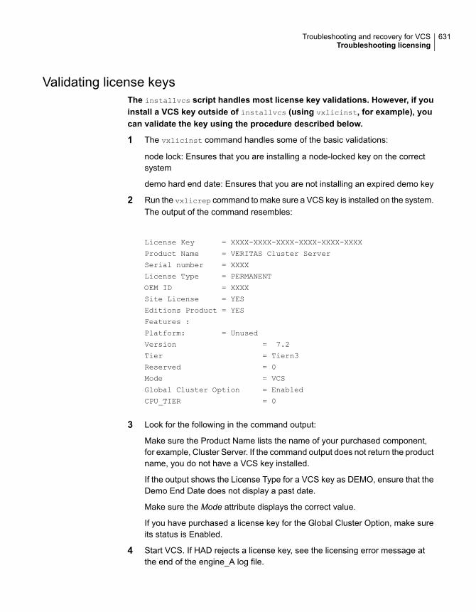
Validating license keysThe installvcs script handles most license key validations. However, if youinstall a VCS key outside of installvcs (using vxlicinst, for example), youcan validate the key using the procedure described below.
1 The vxlicinst command handles some of the basic validations:
node lock: Ensures that you are installing a node-locked key on the correctsystem
demo hard end date: Ensures that you are not installing an expired demo key
2 Run the vxlicrep command to make sure a VCS key is installed on the system.The output of the command resembles:
License Key = XXXX-XXXX-XXXX-XXXX-XXXX-XXXX
Product Name = VERITAS Cluster Server
Serial number = XXXX
License Type = PERMANENT
OEM ID = XXXX
Site License = YES
Editions Product = YES
Features :
Platform: = Unused
Version = 7.2
Tier = Tiern3
Reserved = 0
Mode = VCS
Global Cluster Option = Enabled
CPU_TIER = 0
3 Look for the following in the command output:
Make sure the Product Name lists the name of your purchased component,for example, Cluster Server. If the command output does not return the productname, you do not have a VCS key installed.
If the output shows the License Type for a VCS key as DEMO, ensure that theDemo End Date does not display a past date.
Make sure the Mode attribute displays the correct value.
If you have purchased a license key for the Global Cluster Option, make sureits status is Enabled.
4 Start VCS. If HAD rejects a license key, see the licensing error message atthe end of the engine_A log file.
631Troubleshooting and recovery for VCSTroubleshooting licensing

Licensing error messagesThis section lists the error messages associated with licensing. These messagesare logged to the file /var/VRTSvcs/log/engine_A.log.
[Licensing] Insufficient memory to perform operationThe system does not have adequate resources to perform licensing operations.
[Licensing] No valid VCS license keys were foundNo valid VCS keys were found on the system.
[Licensing] Unable to find a valid base VCS license keyNo valid base VCS key was found on the system.
[Licensing] License key cannot be used on this OSplatformThis message indicates that the license key was meant for a different platform. Forexample, a license key meant for Windows is used on AIX platform.
[Licensing] VCS evaluation period has expiredThe VCS base demo key has expired
[Licensing] License key can not be used on this systemIndicates that you have installed a key that was meant for a different system (i.e.node-locked keys)
[Licensing] Unable to initialize the licensing frameworkThis is a VCS internal message. Call Veritas Technical Support.
[Licensing] QuickStart is not supported in this releaseVCS QuickStart is not supported in this version of VCS.
[Licensing] Your evaluation period for the feature hasexpired. This feature will not be enabled the next time VCSstartsThe evaluation period for the specified VCS feature has expired.
632Troubleshooting and recovery for VCSTroubleshooting licensing
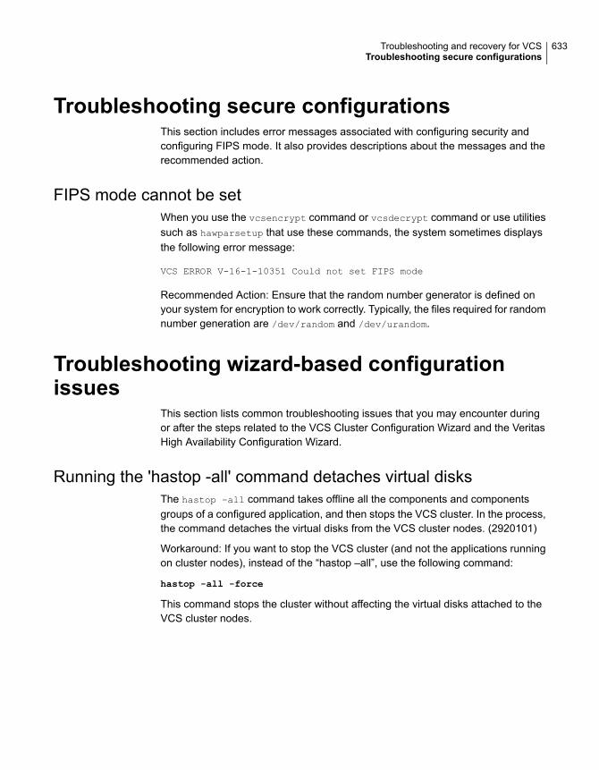
Troubleshooting secure configurationsThis section includes error messages associated with configuring security andconfiguring FIPS mode. It also provides descriptions about the messages and therecommended action.
FIPS mode cannot be setWhen you use the vcsencrypt command or vcsdecrypt command or use utilitiessuch as hawparsetup that use these commands, the system sometimes displaysthe following error message:
VCS ERROR V-16-1-10351 Could not set FIPS mode
Recommended Action: Ensure that the random number generator is defined onyour system for encryption to work correctly. Typically, the files required for randomnumber generation are /dev/random and /dev/urandom.
Troubleshooting wizard-based configurationissues
This section lists common troubleshooting issues that you may encounter duringor after the steps related to the VCS Cluster Configuration Wizard and the VeritasHigh Availability Configuration Wizard.
Running the 'hastop -all' command detaches virtual disksThe hastop –all command takes offline all the components and componentsgroups of a configured application, and then stops the VCS cluster. In the process,the command detaches the virtual disks from the VCS cluster nodes. (2920101)
Workaround: If you want to stop the VCS cluster (and not the applications runningon cluster nodes), instead of the “hastop –all”, use the following command:
hastop -all -force
This command stops the cluster without affecting the virtual disks attached to theVCS cluster nodes.
633Troubleshooting and recovery for VCSTroubleshooting secure configurations

Troubleshooting issues with the Veritas HighAvailability view
This section lists common troubleshooting scenarios that you may encounter whenusing the Veritas High Availability view.
Veritas High Availability view does not display the applicationmonitoring status
The Veritas High Availability view may either display a HTTP 404 Not Found erroror may not show the application health status at all.
Verify the following conditions and then refresh the Veritas High Availability view:
■ Verify that the Veritas High Availability Console host is running and is accessibleover the network.
■ Verify that the VMware Web Service is running on the vCenter Server.
■ Verify that the VMware Tools Service is running on the guest virtual machine.
■ Verify that the Veritas Storage Foundation Messaging Service (xprtld process)is running on the Veritas High Availability Console and the virtual machine. If itis stopped, type the following on the command prompt:net start xprtld
■ Verify that ports 14152, 14153, and 5634 are not blocked by a firewall.
■ Log out of the vSphere Client and then login again. Then, verify that the VeritasHigh Availability plugin is installed and enabled.
Veritas High Availability view may freeze due to special charactersin application display name
For a monitored application, if you specify a display name that contains specialcharacters, one or both of the following symptoms may occur:
■ The Veritas high availability view may freeze
■ The Veritas high availability view may display an Adobe exception error messageBased on your browser settings, the Adobe exception message may or may notappear. However, in both cases the tab may freeze. (2923079)Workaround:Reset the display name using only those characters that belong to the followinglist:
■ any alphanumeric character
634Troubleshooting and recovery for VCSTroubleshooting issues with the Veritas High Availability view

■ space
■ underscoreUse the following command to reset the display name:hagrp -modify sg name UserAssoc -update Name "modified display
name without special characters"
In the Veritas High Availability tab, the Add Failover System link isdimmed
If the system that you clicked in the inventory view of the vSphere Client GUI tolaunch the Veritas High Availability tab is not part of the list of failover target systemsfor that application, the Add Failover System link is dimmed. (2932281)
Workaround: In the vSphere Client GUI inventory view, to launch the Veritas HighAvailability tab, click a system from the existing list of failover target systems forthe application. The Add Failover System link that appears in the drop-down list ifyou click More, is no longer dimmed.
635Troubleshooting and recovery for VCSTroubleshooting issues with the Veritas High Availability view

Appendixes
■ Appendix A. VCS user privileges—administration matrices
■ Appendix B. VCS commands: Quick reference
■ Appendix C. Cluster and system states
■ Appendix D. VCS attributes
■ Appendix E. Accessibility and VCS
8Section

VCS userprivileges—administrationmatrices
This appendix includes the following topics:
■ About administration matrices
■ Administration matrices
About administration matricesIn general, users with Guest privileges can run the following command options:-display, -state, and -value.
Users with privileges for Group Operator and Cluster Operator can execute thefollowing options: -online, -offline, and -switch.
Users with Group Administrator and Cluster Administrator privileges can run thefollowing options -add, -delete, and -modify.
See “About VCS user privileges and roles” on page 79.
Administration matricesReview the matrices in the following topics to determine which command optionscan be executed within a specific user role. Checkmarks denote the command andoption can be executed. A dash indicates they cannot.
AAppendix

Agent Operations (haagent)Table A-1 lists agent operations and required privileges.
Table A-1 User privileges for agent operations
ClusterAdmin.
ClusterOperator
GroupAdmin.
GroupOperator
GuestAgentOperation
✓✓–––Start agent
✓✓–––Stop agent
✓✓✓✓✓Display info
✓✓✓✓✓List agents
Attribute Operations (haattr)Table A-2 lists attribute operations and required privileges.
Table A-2 User privileges for attribute operations
ClusterAdmin.
ClusterOperator
GroupAdmin.
GroupOperator
GuestAttributeOperations
✓––––Add
✓––––Change defaultvalue
✓––––Delete
✓✓✓✓✓Display
Cluster Operations (haclus, haconf)Table A-3 lists cluster operations and required privileges.
Table A-3 User privileges for cluster operations
ClusterAdmin.
ClusterOperator
GroupAdmin.
GroupOperator
ClusterGuest
ClusterOperations
✓✓✓✓✓Display
✓––––Modify
✓––––Add
638VCS user privileges—administration matricesAdministration matrices

Table A-3 User privileges for cluster operations (continued)
ClusterAdmin.
ClusterOperator
GroupAdmin.
GroupOperator
ClusterGuest
ClusterOperations
✓––––Delete
✓✓–––Declare
✓✓✓✓✓View state orstatus
✓––––Update license
✓–✓––Make configurationread-write
✓–✓––Save configuration
✓–✓––Make configurationread-only
Service group operations (hagrp)Table A-4 lists service group operations and required privileges.
Table A-4 User privileges for service group operations
ClusterAdmin.
ClusterOperator
GroupAdmin.
GroupOperator
GuestService GroupOperations
✓––––Add and delete
✓––––Link and unlink
✓✓✓✓–Clear
✓✓✓✓–Bring online
✓✓✓✓–Take offline
✓✓✓✓✓View state
✓✓✓✓–Switch
✓✓✓✓–Freeze/unfreeze
✓–✓––Freeze/unfreezepersistent
✓–✓––Enable
639VCS user privileges—administration matricesAdministration matrices

Table A-4 User privileges for service group operations (continued)
ClusterAdmin.
ClusterOperator
GroupAdmin.
GroupOperator
GuestService GroupOperations
✓–✓––Disable
✓–✓––Modify
✓✓✓✓✓Display
✓✓✓✓✓Viewdependencies
✓✓✓✓✓View resources
✓✓✓✓✓List
✓–✓––Enable resources
✓–✓––Disable resources
✓✓✓✓–Flush
✓✓✓✓–Autoenable
✓✓✓✓–Ignore
Heartbeat operations (hahb)Table A-5 lists heartbeat operations and required privileges.
Table A-5 User privileges for heartbeat operations
ClusterAdmin.
ClusterOperator
GroupAdmin.
GroupOperator
GuestHeartbeatOperations
✓––––Add
✓––––Delete
✓––––Make local
✓––––Make global
✓✓✓✓✓Display
✓✓✓✓✓View state
✓✓✓✓✓List
640VCS user privileges—administration matricesAdministration matrices

Log operations (halog)Table A-6 lists log operations and required privileges.
Table A-6 User privileges for log operations
ClusterAdmin.
ClusterOperator
GroupAdmin.
GroupOperator
GuestLog operations
✓––––Enable debug tags
✓––––Delete debug tags
✓–✓––Add messages tolog file
✓✓✓✓✓Display
✓✓✓✓✓Display log file info
Resource operations (hares)Table A-7 lists resource operations and required privileges.
Table A-7 User privileges for resource operations
ClusterAdmin.
ClusterOperator
GroupAdmin.
GroupOperator
GuestResourceoperations
✓–✓––Add
✓–✓––Delete
✓–✓––Make attributelocal
✓–✓––Make attributeglobal
✓–✓––Link and unlink
✓✓✓✓–Clear
✓✓✓✓–Bring online
✓✓✓✓–Take offline
✓–✓––Modify
✓✓✓✓✓View state
641VCS user privileges—administration matricesAdministration matrices

Table A-7 User privileges for resource operations (continued)
ClusterAdmin.
ClusterOperator
GroupAdmin.
GroupOperator
GuestResourceoperations
✓✓✓✓✓Display
✓✓✓✓✓Viewdependencies
✓✓✓✓✓List, Value
✓✓✓✓–Probe
✓–✓––Override attribute
✓–✓––Remove overrides
✓✓✓✓–Run an action
✓✓✓✓–Refresh info
✓✓✓✓–Flush info
System operations (hasys)Table A-8 lists system operations and required privileges.
Table A-8 User privileges for system operations
ClusterAdmin.
ClusterOperator
GroupAdmin.
GroupOperator
GuestSystemoperations
✓––––Add
✓––––Delete
✓✓–––Freeze andunfreeze
✓––––Freeze andunfreeze persistent
✓––––Freeze andevacuate
✓✓✓✓✓Display
✓––––Start forcibly
✓––––Modify
642VCS user privileges—administration matricesAdministration matrices

Table A-8 User privileges for system operations (continued)
ClusterAdmin.
ClusterOperator
GroupAdmin.
GroupOperator
GuestSystemoperations
✓✓✓✓✓View state
✓✓✓✓✓List
✓––––Update license
Resource type operations (hatype)Table A-9 lists resource type operations and required privileges.
Table A-9 User privileges for resource type operations
ClusterAdmin.
ClusterOperator
GroupAdmin.
GroupOperator
GuestResource typeoperations
✓––––Add
✓––––Delete
✓✓✓✓✓Display
✓✓✓✓✓View resources
✓––––Modify
✓✓✓✓✓List
User operations (hauser)Table A-10 lists user operations and required privileges.
Table A-10 User privileges for user operations
ClusterAdmin.
ClusterOperator
GroupAdmin.
GroupOperator
GuestUser operations
✓––––Add
✓––––Delete
643VCS user privileges—administration matricesAdministration matrices
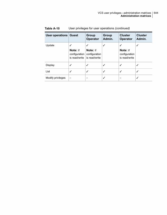
Table A-10 User privileges for user operations (continued)
ClusterAdmin.
ClusterOperator
GroupAdmin.
GroupOperator
GuestUser operations
✓✓
Note: Ifconfigurationis read/write
✓✓
Note: Ifconfigurationis read/write
✓
Note: Ifconfigurationis read/write
Update
✓✓✓✓✓Display
✓✓✓✓✓List
✓–✓––Modify privileges
644VCS user privileges—administration matricesAdministration matrices

VCS commands: Quickreference
This appendix includes the following topics:
■ About this quick reference for VCS commands
■ VCS command line reference
About this quick reference for VCS commandsThis section lists commonly-used VCS commands and options. For more informationabout VCS commands and available options, see the man pages associated withVCS commands.
VCS command line referenceTable B-1 lists the VCS commands for cluster operations.
Table B-1 VCS commands for cluster operations
Command lineCluster operations
hastart [-onenode]
hasys -force system_name
Start VCS
BAppendix

Table B-1 VCS commands for cluster operations (continued)
Command lineCluster operations
hastop -local[-force|-evacuate|-noautodisable]
hastop -local [-force|-evacuate-noautodisable]
hastop -sys system_name[-force|-evacuate|-noautodisable]
hastop -sys system_name [-force|-evacuate-noautodisable]
hastop -all [-force]
Stop VCS
haconf -makerw
haconf -dump -makero
Enable/disable read-writeaccess to VCS configuration
hauser -add user_nameAdd user
Table B-2 lists the VCS commands for service group, resource, and site operations.
Table B-2 VCS commands for service group, resource, and site operations
Command lineService group, resource,or site operations
hagrp -add |-delete group_name
hagrp -modify group attribute value
hagrp -link parent_group child_groupdependency
Configure service groups
hares -add resource type group_name
hares -delete resource_name
hares -modify resource attribute value
hares -link parent_resource child_resource
Configure resources
hatype -modify type attribute valueConfigure agents or resourcetypes
646VCS commands: Quick referenceVCS command line reference

Table B-2 VCS commands for service group, resource, and site operations(continued)
Command lineService group, resource,or site operations
hagrp -online service_group -sys system_name
hagrp -online service_group -site site_name
hagrp -offline service_group -sys system_name
hagrp -offline service_group -site site_name
Bring service groups onlineand take them offline
hares -online resource_name -sys system_name
hares -offline resource_name -sys system_name
Bring resources online andtake them offline
hagrp -freeze group_name [-persistent]
hagrp -unfreeze group_name [-persistent]
Freezing/unfreezing servicegroups
Table B-3 lists the VCS commands for status and verification.
Table B-3 VCS commands for status and verification
Command lineStatus and verification
hastatus -summaryCluster status
lltconfig
lltconfig -a list
lltstat
lltstat -nvv
LLT status/verification
gabconfig -a
gabconfig -av
GAB status/verification
amfconfig
amfstat
AMF kernel driverstatus/verification
Table B-4 lists the VCS commands for cluster communication.
647VCS commands: Quick referenceVCS command line reference

Table B-4 VCS commands for cluster communication
Command lineCommunication
lltconfig -c
lltconfig -U
Starting and stopping LLT
gabconfig -c -n seed_number
gabconfig -U
Starting and stopping GAB
Table B-5 lists the VCS commands for system operations.
Table B-5 VCS commands for system operations
Command lineSystem operations
hasys -listList systems in a cluster
hasys -display system_nameRetrieve detailed informationabout each system
hasys -freeze [-persistent][-evacuate]system_name
hasys -unfreeze [-persistent] system_name
Freezing/unfreezing systems
648VCS commands: Quick referenceVCS command line reference

Cluster and system statesThis appendix includes the following topics:
■ Remote cluster states
■ System states
Remote cluster statesIn global clusters, the "health" of the remote clusters is monitored and maintainedby the wide-area connector process. The connector process uses heartbeats, suchas Icmp, to monitor the state of remote clusters. The state is then communicatedto HAD, which then uses the information to take appropriate action when required.For example, when a cluster is shut down gracefully, the connector transitions itslocal cluster state to EXITING and notifies the remote clusters of the new state.When the cluster exits and the remote connectors lose their TCP/IP connection toit, each remote connector transitions their view of the cluster to EXITED.
To enable wide-area network heartbeats, the wide-area connector process mustbe up and running. For wide-area connectors to connect to remote clusters, at leastone heartbeat to the specified cluster must report the state as ALIVE.
There are three hearbeat states for remote clusters: HBUNKNOWN, HBALIVE, andHBDEAD.
See “Examples of system state transitions” on page 653.
Table C-1 provides a list of VCS remote cluster states and their descriptions.
Table C-1 VCS state definitions
DefinitionState
The initial state of the cluster. This is the default state.INIT
CAppendix

Table C-1 VCS state definitions (continued)
DefinitionState
The local cluster is receiving the initial snapshot from the remote cluster.BUILD
Indicates the remote cluster is running and connected to the localcluster.
RUNNING
The connector process on the local cluster is not receiving heartbeatsfrom the remote cluster
LOST_HB
The connector process on the local cluster has lost the TCP/IPconnection to the remote cluster.
LOST_CONN
The connector process on the local cluster determines the remotecluster is down, but another remote cluster sends a response indicatingotherwise.
UNKNOWN
The remote cluster is down.FAULTED
The remote cluster is exiting gracefully.EXITING
The remote cluster exited gracefully.EXITED
The connector process on the local cluster is querying other clusterson which heartbeats were lost.
INQUIRY
The connector process on the remote cluster is failing over to anothernode in the cluster.
TRANSITIONING
Examples of cluster state transitionsFollowing are examples of cluster state transitions:
■ If a remote cluster joins the global cluster configuration, the other clusters in theconfiguration transition their "view" of the remote cluster to the RUNNING state:INIT -> BUILD -> RUNNING
■ If a cluster loses all heartbeats to a remote cluster in the RUNNING state,inquiries are sent. If all inquiry responses indicate the remote cluster is actuallydown, the cluster transitions the remote cluster state to FAULTED:RUNNING -> LOST_HB -> INQUIRY -> FAULTED
■ If at least one response does not indicate the cluster is down, the clustertransitions the remote cluster state to UNKNOWN:RUNNING -> LOST_HB -> INQUIRY -> UNKNOWN
■ When the ClusterService service group, which maintains the connector processas highly available, fails over to another system in the cluster, the remote clusters
650Cluster and system statesRemote cluster states

transition their view of that cluster to TRANSITIONING, then back to RUNNINGafter the failover is successful:RUNNING -> TRANSITIONING -> BUILD -> RUNNING
■ When a remote cluster in a RUNNING state is stopped (by taking theClusterService service group offline), the remote cluster transitions to EXITED:RUNNING -> EXITING -> EXITED
System statesWhenever the VCS engine is running on a system, it is in one of the states describedin the table below. States indicate a system’s current mode of operation. When theengine is started on a new system, it identifies the other systems available in thecluster and their states of operation. If a cluster system is in the state of RUNNING,the new system retrieves the configuration information from that system. Changesmade to the configuration while it is being retrieved are applied to the new systembefore it enters the RUNNING state.
If no other systems are up and in the state of RUNNING or ADMIN_WAIT, and thenew system has a configuration that is not invalid, the engine transitions to the stateLOCAL_BUILD, and builds the configuration from disk. If the configuration is invalid,the system transitions to the state of STALE_ADMIN_WAIT.
See “Examples of system state transitions” on page 653.
Table C-2 provides a list of VCS system states and their descriptions.
Table C-2 VCS system states
DefinitionState
The running configuration was lost. A system transitions into this statefor the following reasons:
■ The last system in the RUNNING configuration leaves the clusterbefore another system takes a snapshot of its configuration andtransitions to the RUNNING state.
■ A system in LOCAL_BUILD state tries to build the configurationfrom disk and receives an unexpected error from hacf indicatingthe configuration is invalid.
ADMIN_WAIT
The system has joined the cluster and its configuration file is valid.The system is waiting for information from other systems before itdetermines how to transition to another state.
CURRENT_DISCOVER_WAIT
651Cluster and system statesSystem states

Table C-2 VCS system states (continued)
DefinitionState
The system has a valid configuration file and another system is doinga build from disk (LOCAL_BUILD). When its peer finishes the build,this system transitions to the state REMOTE_BUILD.
CURRENT_PEER_WAIT
The system is leaving the cluster.EXITING
The system has left the cluster.EXITED
An hastop -force command has forced the system to leave thecluster.
EXITING_FORCIBLY
The system has left the cluster unexpectedly.FAULTED
The system has joined the cluster. This is the initial state for allsystems.
INITING
The system is leaving the cluster gracefully. When the agents havebeen stopped, and when the current configuration is written to disk,the system transitions to EXITING.
LEAVING
The system is building the running configuration from the diskconfiguration.
LOCAL_BUILD
The system is building a running configuration that it obtained from apeer in a RUNNING state.
REMOTE_BUILD
The system is an active member of the cluster.RUNNING
The system has an invalid configuration and there is no other systemin the state of RUNNING from which to retrieve a configuration. If asystem with a valid configuration is started, that system enters theLOCAL_BUILD state.
Systems in STALE_ADMIN_WAIT transition to STALE_PEER_WAIT.
STALE_ADMIN_WAIT
The system has joined the cluster with an invalid configuration file. Itis waiting for information from any of its peers before determining howto transition to another state.
STALE_DISCOVER_WAIT
The system has an invalid configuration file and another system isdoing a build from disk (LOCAL_BUILD). When its peer finishes thebuild, this system transitions to the state REMOTE_BUILD.
STALE_PEER_WAIT
The system has not joined the cluster because it does not have asystem entry in the configuration.
UNKNOWN
652Cluster and system statesSystem states

Examples of system state transitionsFollowing are examples of system state transitions:
■ If VCS is started on a system, and if that system is the only one in the clusterwith a valid configuration, the system transitions to the RUNNING state:INITING -> CURRENT_DISCOVER_WAIT -> LOCAL_BUILD -> RUNNING
■ If VCS is started on a system with a valid configuration file, and if at least oneother system is already in the RUNNING state, the new system transitions tothe RUNNING state:INITING -> CURRENT_DISCOVER_WAIT -> REMOTE_BUILD -> RUNNING
■ If VCS is started on a system with an invalid configuration file, and if at leastone other system is already in the RUNNING state, the new system transitionsto the RUNNING state:INITING -> STALE_DISCOVER_WAIT -> REMOTE_BUILD -> RUNNING
■ If VCS is started on a system with an invalid configuration file, and if all othersystems are in STALE_ADMIN_WAIT state, the system transitions to theSTALE_ADMIN_WAIT state as shown below. A system stays in this state untilanother system with a valid configuration file is started.INITING -> STALE_DISCOVER_WAIT -> STALE_ADMIN_WAIT
■ If VCS is started on a system with a valid configuration file, and if other systemsare in the ADMIN_WAIT state, the new system transitions to the ADMIN_WAITstate.INITING -> CURRENT_DISCOVER_WAIT -> ADMIN_WAIT
■ If VCS is started on a system with an invalid configuration file, and if othersystems are in the ADMIN_WAIT state, the new system transitions to theADMIN_WAIT state.INITING -> STALE_DISCOVER_WAIT -> ADMIN_WAIT
■ When a system in RUNNING state is stopped with the hastop command, ittransitions to the EXITED state as shown below. During the LEAVING state,any online system resources are taken offline. When all of the system’s resourcesare taken offline and the agents are stopped, the system transitions to theEXITING state, then EXITED.RUNNING -> LEAVING -> EXITING -> EXITED
653Cluster and system statesSystem states

VCS attributesThis appendix includes the following topics:
■ About attributes and their definitions
■ Resource attributes
■ Resource type attributes
■ Service group attributes
■ System attributes
■ Cluster attributes
■ Heartbeat attributes (for global clusters)
■ Remote cluster attributes
■ Site attributes
About attributes and their definitionsIn addition to the attributes listed in this appendix, see the Cluster Server AgentDeveloper’s Guide.
You can modify the values of attributes labelled user-defined from the commandline or graphical user interface, or by manually modifying the main.cf configurationfile. You can change the default values to better suit your environment and enhanceperformance.
When changing the values of attributes, be aware that VCS attributes interact witheach other. After changing the value of an attribute, observe the cluster systemsto confirm that unexpected behavior does not impair performance.
DAppendix

The values of attributes labelled system use only are set by VCS and are read-only.They contain important information about the state of the cluster.
The values labeled agent-defined are set by the corresponding agent and are alsoread-only.
Attribute values are case-sensitive.
See “About VCS attributes” on page 66.
Resource attributesTable D-1 lists resource attributes.
Table D-1 Resource attributes
DescriptionResourceattributes
List of arguments passed to the resource’s agent on each system. This attribute isresource-specific and system-specific, meaning that the list of values passed to the agent dependon which system and resource they are intended.
The number of values in the ArgListValues should not exceed 425. This requirement becomesa consideration if an attribute in the ArgList is a keylist, a vector, or an association. Such typeof non-scalar attributes can typically take any number of values, and when they appear in theArgList, the agent has to compute ArgListValues from the value of such attributes. If the non-scalarattribute contains many values, it will increase the size of ArgListValues. Hence when developingan agent, this consideration should be kept in mind when adding a non-scalar attribute in theArgList. Users of the agent need to be notified that the attribute should not be configured to beso large that it pushes that number of values in the ArgListValues attribute to be more than 425.
■ Type and dimension: string-vector■ Default: non-applicable.
ArgListValues
(agent-defined)
655VCS attributesResource attributes

Table D-1 Resource attributes (continued)
DescriptionResourceattributes
Indicates if a resource should be brought online as part of a service group online, or if it needsthe hares -online command.
For example, you have two resources, R1 and R2. R1 and R2 are in group G1. R1 has anAutoStart value of 0, R2 has an AutoStart value of 1.
In this case, you see the following effects:
# hagrp -online G1 -sys sys1
Brings only R2 to an ONLINE state. The group state is ONLINE and not a PARTIAL state. R1remains OFFLINE.
# hares -online R1 -sys sys1
Brings R1 online, the group state is ONLINE.
# hares -offline R2 -sys sys1
Brings R2 offline, the group state is PARTIAL.
Resources with a value of zero for AutoStart, contribute to the group's state only in their ONLINEstate and not for their OFFLINE state.
■ Type and dimension: boolean-scalar■ Default: 1
AutoStart
(user-defined)
Indicates to agent framework whether or not to calculate the resource’s monitor statistics.
■ Type and dimension: boolean-scalar■ Default: 0
ComputeStats
(user-defined)
Indicates the level of confidence in an online resource. Values range from 0–100. Note thatsome VCS agents may not take advantage of this attribute and may always set it to 0. Set thelevel to 100 if the attribute is not used.
■ Type and dimension: integer-scalar■ Default: 0
ConfidenceLevel
(agent-defined)
Indicates whether a fault of this resource should trigger a failover of the entire group or not. IfCritical is 0 and no parent above has Critical = 1, then the resource fault will not cause groupfailover.
■ Type and dimension: boolean-scalar■ Default: 1
Critical
(user-defined)
656VCS attributesResource attributes

Table D-1 Resource attributes (continued)
DescriptionResourceattributes
Indicates agents monitor the resource.
If a resource is created dynamically while VCS is running, you must enable the resource beforeVCS monitors it. For more information on how to add or enable resources, see the chapters onadministering VCS from the command line and graphical user interfaces.
When Enabled is set to 0, it implies a disabled resource.
See “Troubleshooting VCS startup” on page 600.
■ Type and dimension: boolean-scalar■ Default: If you specify the resource in main.cf prior to starting VCS, the default value for this
attribute is 1, otherwise it is 0.
Enabled
(user-defined)
Provides additional information for the state of a resource. Primarily this attribute raises flagspertaining to the resource. Values:
ADMIN WAIT—The running configuration of a system is lost.
RESTARTING —The agent is attempting to restart the resource because the resource wasdetected as offline in latest monitor cycle unexpectedly. See RestartLimit attribute for moreinformation.
STATE UNKNOWN—The latest monitor call by the agent could not determine if the resourcewas online or offline.
MONITOR TIMEDOUT —The latest monitor call by the agent was terminated because it exceededthe maximum time specified by the static attribute MonitorTimeout.
UNABLE TO OFFLINE—The agent attempted to offline the resource but the resource did notgo offline. This flag is also set when a resource faults and the clean function completessuccessfully, but the subsequent monitor hangs or is unable to determine resource status.
■ Type and dimension: integer-scalar■ Default: Not applicable.
Flags
(system use only)
String name of the service group to which the resource belongs.
■ Type and dimension: string-scalar■ Default: Not applicable.
Group
(system use only)
657VCS attributesResource attributes

Table D-1 Resource attributes (continued)
DescriptionResourceattributes
The internal state of a resource. In addition to the State attribute, this attribute shows to whichstate the resource is transitioning. Values:
NOT WAITING—Resource is not in transition.
WAITING TO GO ONLINE—Agent notified to bring the resource online but procedure not yetcomplete.
WAITING FOR CHILDREN ONLINE—Resource to be brought online, but resource depends onat least one offline resource. Resource transitions to waiting to go online when all children areonline.
WAITING TO GO OFFLINE—Agent notified to take the resource offline but procedure not yetcomplete.
WAITING TO GO OFFLINE (propagate)—Same as above, but when completed the resource’schildren will also be offline.
WAITING TO GO ONLINE (reverse)—Resource waiting to be brought online, but when it isonline it attempts to go offline. Typically this is the result of issuing an offline command whileresource was waiting to go online.
WAITING TO GO OFFLINE (path) - Agent notified to take the resource offline but procedurenot yet complete. When the procedure completes, the resource’s children which are a memberof the path in the dependency tree will also be offline.
WAITING TO GO OFFLINE (reverse) - Resource waiting to be brought offline, but when it isoffline it attempts to go online. Typically this is the result of issuing an online command whileresource was waiting to go offline.
WAITING TO GO ONLINE (reverse/path) - Resource waiting to be brought online, but whenonline it is brought offline. Resource transitions to WAITING TO GO OFFLINE (path). Typicallythis is the result of fault of a child resource while resource was waiting to go online.
WAITING FOR PARENT OFFLINE – Resource waiting for parent resource to go offline. Whenparent is offline the resource is brought offline.
Note: Although this attribute accepts integer types, the command line indicates the textrepresentations.
IState
(system use only)
658VCS attributesResource attributes

Table D-1 Resource attributes (continued)
DescriptionResourceattributes
WAITING TO GO ONLINE (reverse/propagate)—Same as above, but resource propagates theoffline operation.
IStates on the source system for migration operations:
■ WAITING FOR OFFLINE VALIDATION (migrate) – This state is applicable for resource onsource system and indicates that migration operation has been accepted and VCS is validatingwhether migration is possible.
■ WAITING FOR MIGRATION OFFLINE – This state is applicable for resource on sourcesystem and indicates that migration operation has passed the prerequisite checks andvalidations on the source system.
■ WAITING TO COMPLETE MIGRATION – This state is applicable for resource on sourcesystem and indicates that migration process is complete on the source system and the VCSengine is waiting for the resource to come online on target system.
IStates on the target system for migration operations:
■ WAITING FOR ONLINE VALIDATION (migrate) – This state is applicable for resource ontarget system and indicates that migration operations are accepted and VCS is validatingwhether migration is possible.
■ WAITING FOR MIGRATION ONLINE – This state is applicable for resource on target systemand indicates that migration operation has passed the prerequisite checks and validationson the source system.
■ WAITING TO COMPLETE MIGRATION (online) – This state is applicable for resource ontarget system and indicates that migration process is complete on the source system andthe VCS engine is waiting for the resource to come online on target system.
■ Type and dimension: integer-scalar■ Default: 1
NOT WAITING
IState
(system use only)
Indicates the system name on which the resource was last online. This attribute is set by VCS.
■ Type and dimension: string-scalar■ Default: Not applicable
LastOnline
(system use only)
659VCS attributesResource attributes
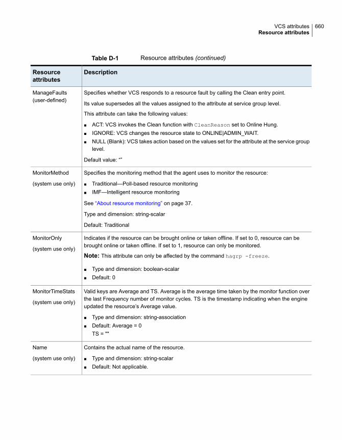
Table D-1 Resource attributes (continued)
DescriptionResourceattributes
Specifies whether VCS responds to a resource fault by calling the Clean entry point.
Its value supersedes all the values assigned to the attribute at service group level.
This attribute can take the following values:
■ ACT: VCS invokes the Clean function with CleanReason set to Online Hung.■ IGNORE: VCS changes the resource state to ONLINE|ADMIN_WAIT.■ NULL (Blank): VCS takes action based on the values set for the attribute at the service group
level.
Default value: “”
ManageFaults(user-defined)
Specifies the monitoring method that the agent uses to monitor the resource:
■ Traditional—Poll-based resource monitoring■ IMF—Intelligent resource monitoring
See “About resource monitoring” on page 37.
Type and dimension: string-scalar
Default: Traditional
MonitorMethod
(system use only)
Indicates if the resource can be brought online or taken offline. If set to 0, resource can bebrought online or taken offline. If set to 1, resource can only be monitored.
Note: This attribute can only be affected by the command hagrp -freeze.
■ Type and dimension: boolean-scalar■ Default: 0
MonitorOnly
(system use only)
Valid keys are Average and TS. Average is the average time taken by the monitor function overthe last Frequency number of monitor cycles. TS is the timestamp indicating when the engineupdated the resource’s Average value.
■ Type and dimension: string-association■ Default: Average = 0
TS = ""
MonitorTimeStats
(system use only)
Contains the actual name of the resource.
■ Type and dimension: string-scalar■ Default: Not applicable.
Name
(system use only)
660VCS attributesResource attributes

Table D-1 Resource attributes (continued)
DescriptionResourceattributes
Set to 1 to identify a resource as a member of a path in the dependency tree to be taken offlineon a specific system after a resource faults.
■ Type and dimension: boolean-scalar■ Default: 0
Path
(system use only)
Indicates whether the state of the resource has been determined by the agent by running themonitor function.
■ Type and dimension: boolean-scalar■ Default: 0
Probed
(system use only)
This attribute has three predefined keys: State: values are Valid, Invalid, or Stale. Msg: outputof the info agent function of the resource on stdout by the agent framework. TS: timestampindicating when the ResourceInfo attribute was updated by the agent framework
■ Type and dimension: string-association■ Default:
State = ValidMsg = ""TS = ""
ResourceInfo
(system use only)
This attribute is used for VCS email notification and logging. VCS sends email notification to theperson that is designated in this attribute when events occur that are related to the resource.Note that while VCS logs most events, not all events trigger notifications. VCS also logs theowner name when certain events occur.
Make sure to set the severity level at which you want notifications to be sent to ResourceOwneror to at least one recipient defined in the SmtpRecipients attribute of the NotifierMngr agent.
■ Type and dimension: string-scalar■ Default: ""■ Example: "[email protected]"
ResourceOwner
(user-defined)
This attribute is used for VCS email notification. VCS sends email notification to personsdesignated in this attribute when events related to the resource occur and when the event'sseverity level is equal to or greater than the level specified in the attribute.
Make sure to set the severity level at which you want notifications to be sent toResourceRecipients or to at least one recipient defined in the SmtpRecipients attribute of theNotifierMngr agent.
■ Type and dimension: string-association■ email id: The e-mail address of the person registered as a recipient for notification.
severity: The minimum level of severity at which notifications must be sent.
ResourceRecipients
(user-defined)
661VCS attributesResource attributes

Table D-1 Resource attributes (continued)
DescriptionResourceattributes
Indicates whether a resource has been traversed. Used when bringing a service group onlineor taking it offline.
■ Type and dimension: integer-association■ Default: Not applicable.
Signaled
(system use only)
Indicates whether a resource was started (the process of bringing it online was initiated) on asystem.
■ Type and dimension: integer -scalar■ Default: 0
Start
(system use only)
Resource state displays the state of the resource and the flags associated with the resource.(Flags are also captured by the Flags attribute.) This attribute and Flags present a comprehensiveview of the resource’s current state. Values:
ONLINE
OFFLINE
FAULTED
OFFLINE|MONITOR TIMEDOUT
OFFLINE|STATE UNKNOWN
OFFLINE|ADMIN WAIT
ONLINE|RESTARTING
ONLINE|MONITOR TIMEDOUT
ONLINE|STATE UNKNOWN
ONLINE|UNABLE TO OFFLINE
ONLINE|ADMIN WAIT
FAULTED|MONITOR TIMEDOUT
FAULTED|STATE UNKNOWN
A FAULTED resource is physically offline, though unintentionally.
Note: Although this attribute accepts integer types, the command line indicates the textrepresentations.
Type and dimension: integer -scalar
Default: 0
State
(system use only)
662VCS attributesResource attributes

Table D-1 Resource attributes (continued)
DescriptionResourceattributes
A flag that turns Events on or off.
■ Type and dimension: boolean-scalar■ Default: 0
TriggerEvent
(user-defined)
Enables you to customize the trigger path.
■ Type and dimension: string-scalar■ Default: ""
If a trigger is enabled but the trigger path at the service group level and at the resource level is"" (default), VCS invokes the trigger from the $VCS_HOME/bin/triggers directory.
The TriggerPath value is case-sensitive. VCS does not trim the leading spaces or trailing spacesin the Trigger Path value. If the path contains leading spaces or trailing spaces, the trigger mightfail to get executed. The path that you specify is relative to $VCS_HOME and the trigger pathdefined for the service group.
Specify the path in the following format:
ServiceGroupTriggerPath/Resource/Trigger
If TriggerPath for service group sg1 is mytriggers/sg1 and TriggerPath for resource res1 is "",you must store the trigger script in the $VCS_HOME/mytriggers/sg1/res1 directory. For example,store the resstatechange trigger script in the $VCS_HOME/mytriggers/sg1/res1 directory. Yoncan manage triggers for all resources for a service group more easily.
If TriggerPath for resource res1 is mytriggers/sg1/vip1 in the preceding example, you must storethe trigger script in the $VCS_HOME/mytriggers/sg1/vip1 directory. For example, store theresstatechange trigger script in the $VCS_HOME/mytriggers/sg1/vip1 directory.
Modification of TriggerPath value at the resource level does not change the TriggerPath valueat the service group level. Likewise, modification of TriggerPath value at the service group leveldoes not change the TriggerPath value at the resource level.
TriggerPath
(user-defined)
Determines whether or not to invoke the resrestart trigger if resource restarts.
See “About the resrestart event trigger” on page 430.
If this attribute is enabled at the group level, the resrestart trigger is invoked irrespective of thevalue of this attribute at the resource level.
See “Service group attributes” on page 680.
■ Type and dimension: boolean-scalar■ Default: 0 (disabled)
TriggerResRestart
(user-defined)
663VCS attributesResource attributes

Table D-1 Resource attributes (continued)
DescriptionResourceattributes
Determines whether or not to invoke the resstatechange trigger if the resource changes state.
See “About the resstatechange event trigger” on page 431.
If this attribute is enabled at the group level, then the resstatechange trigger is invoked irrespectiveof the value of this attribute at the resource level.
See “Service group attributes” on page 680.
■ Type and dimension: boolean-scalar■ Default: 0 (disabled)
TriggerResStateChange
(user-defined)
Determines if a specific trigger is enabled or not.
Triggers are disabled by default. You can enable specific triggers on all nodes or only on selectednodes. Valid values are RESFAULT, RESNOTOFF, RESSTATECHANGE, RESRESTART, andRESADMINWAIT.
To enable triggers on a specific node, add trigger keys in the following format:
TriggersEnabled@node1 = {RESADMINWAIT, RESNOTOFF}
The resadminwait trigger and resnotoff trigger are enabled on node1.
To enable triggers on all nodes in the cluster, add trigger keys in the following format:
TriggersEnabled = {RESADMINWAIT, RESNOTOFF}
The resadminwait trigger and resnotoff trigger are enabled on all nodes.
■ Type and dimension: string-keylist■ Default: {}
TriggersEnabled
(user-defined)
Resource type attributesYou can override some static attributes for resource types.
For more information on any attribute listed below, see the chapter on setting agentparameters in the Cluster Server Agent Developer’s Guide.
Table D-2 lists the resource type attributes.
664VCS attributesResource type attributes
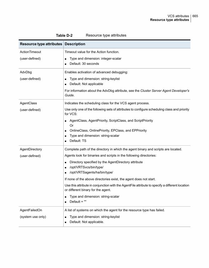
Table D-2 Resource type attributes
DescriptionResource type attributes
Timeout value for the Action function.
■ Type and dimension: integer-scalar■ Default: 30 seconds
ActionTimeout
(user-defined)
Enables activation of advanced debugging:
■ Type and dimension: string-keylist■ Default: Not applicable
For information about the AdvDbg attribute, see the Cluster Server Agent Developer'sGuide.
AdvDbg
(user-defined)
Indicates the scheduling class for the VCS agent process.
Use only one of the following sets of attributes to configure scheduling class and priorityfor VCS:
■ AgentClass, AgentPriority, ScriptClass, and ScriptPriorityOr
■ OnlineClass, OnlinePriority, EPClass, and EPPriority■ Type and dimension: string-scalar■ Default: TS
AgentClass
(user-defined)
Complete path of the directory in which the agent binary and scripts are located.
Agents look for binaries and scripts in the following directories:
■ Directory specified by the AgentDirectory attribute■ /opt/VRTSvcs/bin/type/■ /opt/VRTSagents/ha/bin/type/
If none of the above directories exist, the agent does not start.
Use this attribute in conjunction with the AgentFile attribute to specify a different locationor different binary for the agent.
■ Type and dimension: string-scalar■ Default = ""
AgentDirectory
(user-defined)
A list of systems on which the agent for the resource type has failed.
■ Type and dimension: string-keylist■ Default: Not applicable.
AgentFailedOn
(system use only)
665VCS attributesResource type attributes

Table D-2 Resource type attributes (continued)
DescriptionResource type attributes
Complete name and path of the binary for an agent. If you do not specify a value forthis attribute, VCS uses the agent binary at the path defined by the AgentDirectoryattribute.
■ Type and dimension: string-scalar■ Default = ""
AgentFile
(user-defined)
Indicates the priority in which the agent process runs.
Use only one of the following sets of attributes to configure scheduling class and priorityfor VCS:
■ AgentClass, AgentPriority, ScriptClass, and ScriptPriorityOr
■ OnlineClass, OnlinePriority, EPClass, and EPPriority
Type and dimension: string-scalar
Default: 0
AgentPriority
(user-defined)
The number of seconds the engine waits to receive a heartbeat from the agent beforerestarting the agent.
■ Type and dimension: integer-scalar■ Default: 130 seconds
AgentReplyTimeout
(user-defined)
The number of seconds after starting the agent that the engine waits for the initial agent"handshake" before restarting the agent.
■ Type and dimension: integer-scalar■ Default: 60 seconds
AgentStartTimeout
(user-defined)
666VCS attributesResource type attributes
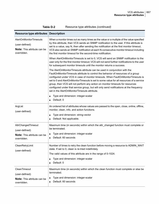
Table D-2 Resource type attributes (continued)
DescriptionResource type attributes
When a monitor times out as many times as the value or a multiple of the value specifiedby this attribute, then VCS sends an SNMP notification to the user. If this attribute isset to a value, say N, then after sending the notification at the first monitor timeout,VCS also sends an SNMP notification at each N-consecutive monitor timeout includingthe first monitor timeout for the second-time notification.
When AlertOnMonitorTimeouts is set to 0, VCS will send an SNMP notification to theuser only for the first monitor timeout; VCS will not send further notifications to the userfor subsequent monitor timeouts until the monitor returns a success.
The AlertOnMonitorTimeouts attribute can be used in conjunction with theFaultOnMonitorTimeouts attribute to control the behavior of resources of a groupconfigured under VCS in case of monitor timeouts. When FaultOnMonitorTimeouts isset to 0 and AlertOnMonitorTimeouts is set to some value for all resources of a servicegroup, then VCS will not perform any action on monitor timeouts for resourcesconfigured under that service group, but will only send notifications at the frequencyset in the AlertOnMonitorTimeouts attribute.
■ Type and dimension: integer-scalar■ Default: 0
AlertOnMonitorTimeouts
(user-defined)
Note: This attribute can beoverridden.
An ordered list of attributes whose values are passed to the open, close, online, offline,monitor, clean, info, and action functions.
■ Type and dimension: string-vector■ Default: Not applicable.
ArgList
(user-defined)
Maximum time (in seconds) within which the attr_changed function must complete orbe terminated.
■ Type and dimension: integer-scalar■ Default: 60 seconds
AttrChangedTimeout
(user-defined)
Note: This attribute can beoverridden.
Number of times to retry the clean function before moving a resource to ADMIN_WAITstate. If set to 0, clean is re-tried indefinitely.
The valid values of this attribute are in the range of 0-1024.
■ Type and dimension: integer-scalar■ Default: 0
CleanRetryLimit
(user-defined)
Maximum time (in seconds) within which the clean function must complete or else beterminated.
■ Type and dimension: integer-scalar■ Default: 60 seconds
CleanTimeout
(user-defined)
Note: This attribute can beoverridden.
667VCS attributesResource type attributes

Table D-2 Resource type attributes (continued)
DescriptionResource type attributes
Maximum time (in seconds) within which the close function must complete or else beterminated.
■ Type and dimension: integer-scalar■ Default: 60 seconds
CloseTimeout
(user-defined)
Note: This attribute can beoverridden.
When a resource has remained online for the specified time (in seconds), previousfaults and restart attempts are ignored by the agent. (See ToleranceLimit andRestartLimit attributes for details.)
■ Type and dimension: integer-scalar■ Default: 600 seconds
ConfInterval
(user-defined)
Note: This attribute can beoverridden.
Specifies information that passes to the agent that controls the resources. These valuesare only effective when you set the ContainerInfo service group attribute.
■ RunInContainerWhen the value of the RunInContainer key is 1, the agent function (entry point) forthat resource runs inside of the local container.When the value of the RunInContainer key is 0, the agent function (entry point) forthat resource runs outside the local container (in the global environment).
■ PassCInfoWhen the value of the PassCInfo key is 1, the agent function receives the containerinformation that is defined in the service group’s ContainerInfo attribute. An exampleuse of this value is to pass the name of the container to the agent. When the valueof the PassCInfo key is 0, the agent function does not receive the containerinformation that is defined in the service group’s ContainerInfo attribute.
ContainerOpts
(system use only)
Enables you to control the scheduling class for the agent functions (entry points) otherthan the online entry point whether the entry point is in C or scripts.
The following values are valid for this attribute:
■ RT (Real Time)■ TS (Time Sharing)■ -1—indicates that VCS does not use this attribute to control the scheduling class
of entry points.
Use only one of the following sets of attributes to configure scheduling class and priorityfor VCS:
■ AgentClass, AgentPriority, ScriptClass, and ScriptPriorityOr
■ OnlineClass, OnlinePriority, EPClass, and EPPriority■ Type and dimension: string-scalar■ Default: -1
EPClass
(user-defined)
668VCS attributesResource type attributes
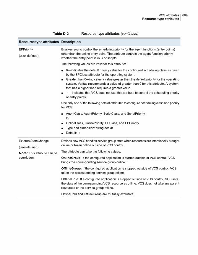
Table D-2 Resource type attributes (continued)
DescriptionResource type attributes
Enables you to control the scheduling priority for the agent functions (entry points)other than the online entry point. The attribute controls the agent function prioritywhether the entry point is in C or scripts.
The following values are valid for this attribute:
■ 0—indicates the default priority value for the configured scheduling class as givenby the EPClass attribute for the operating system.
■ Greater than 0—indicates a value greater than the default priority for the operatingsystem. Veritas recommends a value of greater than 0 for this attribute. A systemthat has a higher load requires a greater value.
■ -1—indicates that VCS does not use this attribute to control the scheduling priorityof entry points.
Use only one of the following sets of attributes to configure scheduling class and priorityfor VCS:
■ AgentClass, AgentPriority, ScriptClass, and ScriptPriorityOr
■ OnlineClass, OnlinePriority, EPClass, and EPPriority■ Type and dimension: string-scalar■ Default: -1
EPPriority
(user-defined)
Defines how VCS handles service group state when resources are intentionally broughtonline or taken offline outside of VCS control.
The attribute can take the following values:
OnlineGroup: If the configured application is started outside of VCS control, VCSbrings the corresponding service group online.
OfflineGroup: If the configured application is stopped outside of VCS control, VCStakes the corresponding service group offline.
OfflineHold: If a configured application is stopped outside of VCS control, VCS setsthe state of the corresponding VCS resource as offline. VCS does not take any parentresources or the service group offline.
OfflineHold and OfflineGroup are mutually exclusive.
ExternalStateChange
(user-defined)
Note: This attribute can beoverridden.
669VCS attributesResource type attributes

Table D-2 Resource type attributes (continued)
DescriptionResource type attributes
When a monitor times out as many times as the value specified, the correspondingresource is brought down by calling the clean function. The resource is then markedFAULTED, or it is restarted, depending on the value set in the RestartLimit attribute.
When FaultOnMonitorTimeouts is set to 0, monitor failures are not considered indicativeof a resource fault. A low value may lead to spurious resource faults, especially onheavily loaded systems.
■ Type and dimension: integer-scalar■ Default: 4
FaultOnMonitorTimeouts
(user-defined)
Note: This attribute can beoverridden.
Specifies if VCS should propagate the fault up to parent resources and take the entireservice group offline when a resource faults.
The value 1 indicates that when a resource faults, VCS fails over the service group, ifthe group’s AutoFailOver attribute is set to 1. The value 0 indicates that when a resourcefaults, VCS does not take other resources offline, regardless of the value of the Criticalattribute. The service group does not fail over on resource fault.
■ Type and dimension: boolean-scalar■ Default: 1
FaultPropagation
(user-defined)
Note: This attribute can beoverridden.
Specifies whether or not fire drill is enabled for the resource type. If the value is:
■ 0: Fire drill is disabled.■ 1: Fire drill is enabled.
You can override this attribute.
■ Type and dimension: boolean-scalar■ Default: 0
FireDrill
(user-defined)
670VCS attributesResource type attributes

Table D-2 Resource type attributes (continued)
DescriptionResource type attributes
Determines whether the IMF-aware agent must perform intelligent resource monitoring.You can also override the value of this attribute at resource-level.
Type and dimension: integer-association
This attribute includes the following keys:
■ ModeDefine this attribute to enable or disable intelligent resource monitoring.
Valid values are as follows:■ 0—Does not perform intelligent resource monitoring■ 1—Performs intelligent resource monitoring for offline resources and performs
poll-based monitoring for online resources■ 2—Performs intelligent resource monitoring for online resources and performs
poll-based monitoring for offline resources■ 3—Performs intelligent resource monitoring for both online and for offline
resources■ MonitorFreq
This key value specifies the frequency at which the agent invokes the monitor agentfunction. The value of this key is an integer.You can set this attribute to a non-zero value in some cases where the agentrequires to perform poll-based resource monitoring in addition to the intelligentresource monitoring. See the Cluster Server Bundled Agents Reference Guide foragent-specific recommendations.
After the resource registers with the IMF notification module, the agent calls themonitor agent function as follows:■ After every (MonitorFreq x MonitorInterval) number of seconds for online
resources■ After every (MonitorFreq x OfflineMonitorInterval) number of seconds for offline
resources■ RegisterRetryLimit
If you enable IMF, the agent invokes the imf_register agent function to register theresource with the IMF notification module. The value of the RegisterRetyLimit keydetermines the number of times the agent must retry registration for a resource. Ifthe agent cannot register the resource within the limit that is specified, then intelligentmonitoring is disabled until the resource state changes or the value of the Modekey changes.
IMF
(user-defined)
Note: This attribute can beoverridden.
An ordered list of attributes whose values are registered with the IMF notificationmodule.
■ Type and dimension: string-vector■ Default: Not applicable.
IMFRegList
(user-defined)
671VCS attributesResource type attributes

Table D-2 Resource type attributes (continued)
DescriptionResource type attributes
Duration (in seconds) after which the info function is invoked by the agent frameworkfor ONLINE resources of the particular resource type.
If set to 0, the agent framework does not periodically invoke the info function. Tomanually invoke the info function, use the command hares -refreshinfo. If the valueyou designate is 30, for example, the function is invoked every 30 seconds for allONLINE resources of the particular resource type.
■ Type and dimension: integer-scalar■ Default: 0
InfoInterval
(user-defined)
Defines how VCS reacts when a configured application is intentionally stopped outsideof VCS control.
Add this attribute for agents that support detection of an intentional offline outside ofVCS control. Note that the intentional offline feature is available for agents registeredas V51 or later.
The value 0 instructs the agent to register a fault and initiate the failover of a servicegroup when the supported resource is taken offline outside of VCS control.
The value 1 instructs VCS to take the resource offline when the correspondingapplication is stopped outside of VCS control.
■ Type and dimension: boolean-scalar■ Default: 0
IntentionalOffline
(user-defined)
Timeout value for info function. If function does not complete by the designated time,the agent framework cancels the function’s thread.
■ Type and dimension: integer-scalar■ Default: 30 seconds
InfoTimeout
(user-defined)
Specifies the frequency at which the agent for this resource type must performsecond-level or detailed monitoring.
Type and dimension: integer-scalar
Default: 0
LevelTwoMonitorFreq
(user-defined)
672VCS attributesResource type attributes
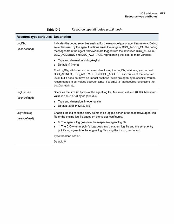
Table D-2 Resource type attributes (continued)
DescriptionResource type attributes
Indicates the debug severities enabled for the resource type or agent framework. Debugseverities used by the agent functions are in the range of DBG_1–DBG_21. The debugmessages from the agent framework are logged with the severities DBG_AGINFO,DBG_AGDEBUG and DBG_AGTRACE, representing the least to most verbose.
■ Type and dimension: string-keylist■ Default: {} (none)
The LogDbg attribute can be overridden. Using the LogDbg attribute, you can setDBG_AGINFO, DBG_AGTRACE, and DBG_AGDEBUG severities at the resourcelevel, but it does not have an impact as these levels are agent-type specific. Veritasrecommends to set values between DBG_1 to DBG_21 at resource level using theLogDbg attribute.
LogDbg
(user-defined)
Specifies the size (in bytes) of the agent log file. Minimum value is 64 KB. Maximumvalue is 134217728 bytes (128MB).
■ Type and dimension: integer-scalar■ Default: 33554432 (32 MB)
LogFileSize
(user-defined)
Enables the log of all the entry points to be logged either in the respective agent logfile or the engine log file based on the values configured.
■ 0: The agent’s log goes into the respective agent log file.■ 1: The C/C++ entry point’s logs goes into the agent log file and the script entry
point’s logs goes into the engine log file using the halog command.
Type: boolean-scalar
Default: 0
LogViaHalog
(user-defined)
673VCS attributesResource type attributes

Table D-2 Resource type attributes (continued)
DescriptionResource type attributes
Number of monitor intervals to wait for a resource to migrate after the migratingprocedure is complete. MigrateWaitLimit is applicable for the source and target nodebecause the migrate operation takes the resource offline on the source node and bringsthe resource online on the target node. You can also define MigrateWaitLimit as thenumber of monitor intervals to wait for the resource to go offline on the source nodeafter completing the migrate procedure and the number of monitor intervals to wait forthe resource to come online on the target node after resource is offline on the sourcenode.
■ Type and dimension: integer-scalar■ Default: 2
Note: This attribute can be overridden.
Probes fired manually are counted when MigrateWaitLimit is set and the resource iswaiting to migrate. For example, if the MigrateWaitLimit of a resource is set to 5 andthe MonitorInterval is set to 60 (seconds), the resource waits for a maximum of fivemonitor intervals (that is, 5 x 60), and if all five monitors within MigrateWaitLimit reportthe resource as online on source node, it sets the ADMIN_WAIT flag. If you run anotherprobe, the resource waits for four monitor intervals (that is, 4 x 60), and if the fourthmonitor does not report the state as offline on source, it sets the ADMIN_WAIT flag.This procedure is repeated for 5 complete cycles. Similarly, if resource not moved toonline state within the MigrateWaitLimit then it sets the ADMIN_WAIT flag.
MigrateWaitLimit
(user-defined)
Maximum time (in seconds) within which the migrate procedure must complete or elsebe terminated.
■ Type and dimension: integer-scalar■ Default: 600 seconds
Note: This attribute can be overridden.
MigrateTimeout
(user-defined)
Duration (in seconds) between two consecutive monitor calls for an ONLINE ortransitioning resource.
Note: Note: The value of this attribute for the MultiNICB type must be less than itsvalue for the IPMultiNICB type. See the Cluster Server Bundled Agents ReferenceGuide for more information.
A low value may impact performance if many resources of the same type exist. A highvalue may delay detection of a faulted resource.
■ Type and dimension: integer-scalar■ Default: 60 seconds
MonitorInterval
(user-defined)
Note: This attribute can beoverridden.
674VCS attributesResource type attributes
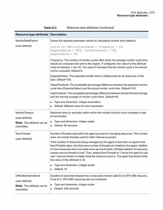
Table D-2 Resource type attributes (continued)
DescriptionResource type attributes
Stores the required parameter values for calculating monitor time statistics.
static str MonitorStatsParam = {Frequency = 10,ExpectedValue = 3000, ValueThreshold = 100,AvgThreshold = 40}
Frequency: The number of monitor cycles after which the average monitor cycle timeshould be computed and sent to the engine. If configured, the value for this attributemust be between 1 and 30. The value 0 indicates that the monitor cycle ti me shouldnot be computed. Default=0.
ExpectedValue: The expected monitor time in milliseconds for all resources of thistype. Default=100.
ValueThreshold: The acceptable percentage difference between the expected monitorcycle time (ExpectedValue) and the actual monitor cycle time. Default=100.
AvgThreshold: The acceptable percentage difference between the benchmark averageand the moving average of monitor cycle times. Default=40.
■ Type and dimension: integer-association■ Default: Different value for each parameter.
MonitorStatsParam
(user-defined)
Maximum time (in seconds) within which the monitor function must complete or elsebe terminated.
■ Type and dimension: integer-scalar■ Default: 60 seconds
MonitorTimeout
(user-defined)
Note: This attribute can beoverridden.
Number of threads used within the agent process for managing resources. This numberdoes not include threads used for other internal purposes.
If the number of resources being managed by the agent is less than or equal to theNumThreads value, only that many number of threads are created in the agent. Additionof more resources does not create more service threads. Similarly deletion of resourcescauses service threads to exit. Thus, setting NumThreads to 1 forces the agent to justuse 1 service thread no matter what the resource count is. The agent framework limitsthe value of this attribute to 30.
■ Type and dimension: integer-scalar■ Default: 10
NumThreads
(user-defined)
Duration (in seconds) between two consecutive monitor calls for an OFFLINE resource.If set to 0, OFFLINE resources are not monitored.
■ Type and dimension: integer-scalar■ Default: 300 seconds
OfflineMonitorInterval
(user-defined)
Note: This attribute can beoverridden.
675VCS attributesResource type attributes

Table D-2 Resource type attributes (continued)
DescriptionResource type attributes
Maximum time (in seconds) within which the offline function must complete or else beterminated.
■ Type and dimension: integer-scalar■ Default: 300 seconds
OfflineTimeout
(user-defined)
Note: This attribute can beoverridden.
Number of monitor intervals to wait for the resource to go offline after completing theoffline procedure. Increase the value of this attribute if the resource is likely to take alonger time to go offline.
Probes fired manually are counted when OfflineWaitLimit is set and the resource iswaiting to go offline. For example, say the OfflineWaitLimit of a resource is set to 5 andthe MonitorInterval is set to 60. The resource waits for a maximum of five monitorintervals (five times 60), and if all five monitors within OfflineWaitLimit report the resourceas online, it calls the clean agent function. If the user fires a probe, the resource waitsfor four monitor intervals (four times 60), and if the fourth monitor does not report thestate as offline, it calls the clean agent function. If the user fires another probe, onemore monitor cycle is consumed and the resource waits for three monitor intervals(three times 60), and if the third monitor does not report the state as offline, it calls theclean agent function.
■ Type and dimension: integer-scalar■ Default: 0
OfflineWaitLimit
(user-defined)
Note: This attribute can beoverridden.
Enables you to control the scheduling class for the online agent function (entry point).This attribute controls the class whether the entry point is in C or scripts.
The following values are valid for this attribute:
■ RT (Real Time)■ TS (Time Sharing)■ -1—indicates that VCS does not use this attribute to control the scheduling class
of entry points.
Use only one of the following sets of attributes to configure scheduling class and priorityfor VCS:
■ AgentClass, AgentPriority, ScriptClass, and ScriptPriorityOr
■ OnlineClass, OnlinePriority, EPClass, and EPPriority■ Type and dimension: string-scalar■ Default: -1
OnlineClass
(user-defined)
676VCS attributesResource type attributes

Table D-2 Resource type attributes (continued)
DescriptionResource type attributes
Enables you to control the scheduling priority for the online agent function (entry point).This attribute controls the priority whether the entry point is in C or scripts.
The following values are valid for this attribute:
■ 0—indicates the default priority value for the configured scheduling class as givenby the OnlineClass for the operating system.Veritas recommends that you set the value of the OnlinePriority attribute to 0.
■ Greater than 0—indicates a value greater than the default priority for the operatingsystem.
■ -1—indicates that VCS does not use this attribute to control the scheduling priorityof entry points.
Use only one of the following sets of attributes to configure scheduling class and priorityfor VCS:
■ AgentClass, AgentPriority, ScriptClass, and ScriptPriorityOr
■ OnlineClass, OnlinePriority, EPClass, and EPPriority■ Type and dimension: string-scalar■ Default: -1
OnlinePriority
(user-defined)
Number of times to retry the online operation if the attempt to online a resource isunsuccessful. This parameter is meaningful only if the clean operation is implemented.
■ Type and dimension: integer-scalar■ Default: 0
OnlineRetryLimit
(user-defined)
Note: This attribute can beoverridden.
Maximum time (in seconds) within which the online function must complete or else beterminated.
■ Type and dimension: integer-scalar■ Default: 300 seconds
OnlineTimeout
(user-defined)
Note: This attribute can beoverridden.
677VCS attributesResource type attributes
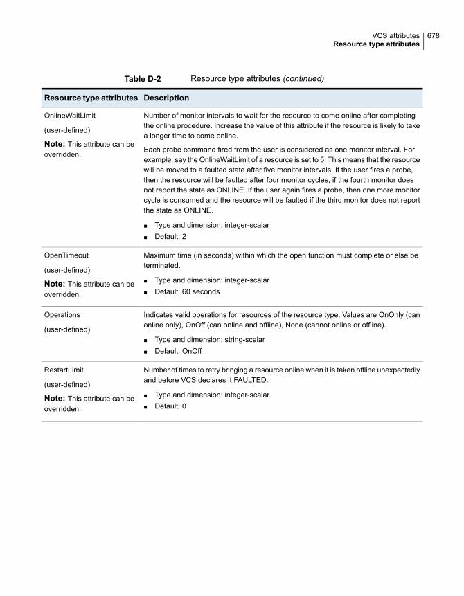
Table D-2 Resource type attributes (continued)
DescriptionResource type attributes
Number of monitor intervals to wait for the resource to come online after completingthe online procedure. Increase the value of this attribute if the resource is likely to takea longer time to come online.
Each probe command fired from the user is considered as one monitor interval. Forexample, say the OnlineWaitLimit of a resource is set to 5. This means that the resourcewill be moved to a faulted state after five monitor intervals. If the user fires a probe,then the resource will be faulted after four monitor cycles, if the fourth monitor doesnot report the state as ONLINE. If the user again fires a probe, then one more monitorcycle is consumed and the resource will be faulted if the third monitor does not reportthe state as ONLINE.
■ Type and dimension: integer-scalar■ Default: 2
OnlineWaitLimit
(user-defined)
Note: This attribute can beoverridden.
Maximum time (in seconds) within which the open function must complete or else beterminated.
■ Type and dimension: integer-scalar■ Default: 60 seconds
OpenTimeout
(user-defined)
Note: This attribute can beoverridden.
Indicates valid operations for resources of the resource type. Values are OnOnly (canonline only), OnOff (can online and offline), None (cannot online or offline).
■ Type and dimension: string-scalar■ Default: OnOff
Operations
(user-defined)
Number of times to retry bringing a resource online when it is taken offline unexpectedlyand before VCS declares it FAULTED.
■ Type and dimension: integer-scalar■ Default: 0
RestartLimit
(user-defined)
Note: This attribute can beoverridden.
678VCS attributesResource type attributes

Table D-2 Resource type attributes (continued)
DescriptionResource type attributes
Indicates the scheduling class of the script processes (for example, online) created bythe agent.
Use only one of the following sets of attributes to configure scheduling class and priorityfor VCS:
■ AgentClass, AgentPriority, ScriptClass, and ScriptPriorityOr
■ OnlineClass, OnlinePriority, EPClass, and EPPriority■ Type and dimension: string-scalar■ Default: -1■ Type and dimension: string-scalar■ Default: TS
ScriptClass
(user-defined)
Indicates the priority of the script processes created by the agent.
Use only one of the following sets of attributes to configure scheduling class and priorityfor VCS:
■ AgentClass, AgentPriority, ScriptClass, and ScriptPriorityOr
■ OnlineClass, OnlinePriority, EPClass, and EPPriority■ Type and dimension: string-scalar■ Default: 0
ScriptPriority
(user-defined)
File from which the configuration is read. Do not configure this attribute in main.cf.
Make sure the path exists on all nodes before running a command that configures thisattribute.
■ Type and dimension: string-scalar■ Default: .\types.cf
SourceFile
(user-defined)
Valid action tokens for the resource type.
■ Type and dimension: string-vector■ Default: {}
SupportedActions
(user-defined)
Indicates the additional operations for a resource type or an agent. Only migrate
keyword is supported.
■ Type and dimension: string-keylist■ Default: {}
An example of a resource type that supports migration is a logical partition (LPAR).
SupportedOperations
(user-defined)
679VCS attributesResource type attributes

Table D-2 Resource type attributes (continued)
DescriptionResource type attributes
After a resource goes online, the number of times the monitor function should returnOFFLINE before declaring the resource FAULTED.
A large value could delay detection of a genuinely faulted resource.
■ Type and dimension: integer-scalar■ Default: 0
ToleranceLimit
(user-defined)
Note: This attribute can beoverridden.
This attribute is used for VCS notification. VCS sends notifications to persons designatedin this attribute when an event occurs related to the agent's resource type. If the agentof that type faults or restarts, VCS send notification to the TypeOwner. Note that whileVCS logs most events, not all events trigger notifications.
Make sure to set the severity level at which you want notifications to be sent toTypeOwner or to at least one recipient defined in the SmtpRecipients attribute of theNotifierMngr agent.
■ Type and dimension: string-scalar■ Default: ""■ Example: "[email protected]"
TypeOwner
(user-defined)
The email-ids set in the TypeRecipients attribute receive email notification for eventsrelated to a specific agent. There are only two types of events related to an agent forwhich notifications are sent:
■ Agent fault - Warning■ Agent restart - Information
TypeRecipients
(user-defined)
Service group attributesTable D-3 lists the service group attributes.
Table D-3 Service group attributes
DefinitionService GroupAttributes
Number of resources in a service group that are active (online orwaiting to go online). When the number drops to zero, the servicegroup is considered offline.
■ Type and dimension: integer-scalar■ Default: Not applicable.
ActiveCount
(system use only)
680VCS attributesService group attributes

Table D-3 Service group attributes (continued)
DefinitionService GroupAttributes
List of operating system user account groups that have administrativeprivileges on the service group.
This attribute applies to clusters running in secure mode.
■ Type and dimension: string-keylist■ Default: {} (none)
AdministratorGroups
(user-defined)
List of VCS users with privileges to administer the group.
Note: A Group Administrator can perform all operations related toa specific service group, but cannot perform generic clusteroperations.
See “About VCS user privileges and roles” on page 79.
■ Type and dimension: string-keylist■ Default: {} (none)
Administrators
(user-defined)
Indicates whether or not the local cluster is allowed to bring theservice group online. If set to 0, it is not, if set to 1, it is. Only onecluster can have this attribute set to 1 for a specific global group.
See “About serialization–The Authority attribute” on page 466.
■ Type and dimension: integer-scalar■ Default: 0
Authority
(user-defined)
Indicates the number of attempts that the VCS engine made to clearthe state of the service group that has faulted and does not have afailover target. This attribute is used only if the AutoClearLimitattribute is set for the service group.
AutoClearCount
(System use only)
Indicates the interval in seconds after which a service group that hasfaulted and has no failover target is cleared automatically. The stateof the service group is cleared only if AutoClearLimit is set to anon-zero value.
Default: 0
AutoClearInterval
(user-defined)
Defines the number of attempts to be made to clear the Faulted stateof a service group. Disables the auto-clear feature when set to zero.
AutoclearLimit
(user-defined)
681VCS attributesService group attributes

Table D-3 Service group attributes (continued)
DefinitionService GroupAttributes
Indicates that VCS does not know the status of a service group (orspecified system for parallel service groups). This could occurbecause the group is not probed (on specified system for parallelgroups) in the SystemList attribute. Or the VCS engine is not runningon a node designated in the SystemList attribute, but the node isvisible.
When VCS does not know the status of a service group on a nodebut you want VCS to consider the service group enabled, performthis command to change the AutoDisabled value to 0.
hagrp -autoenable grp -sys sys1
This command instructs VCS that even though VCS has marked theservice group auto-disabled, you are sure that the service group isnot online on sys1. For failover service groups, this is importantbecause the service groups now can be brought online on remainingnodes.
■ Type and dimension: boolean-scalar■ Default: 0
AutoDisabled
(system use only)
Indicates whether VCS initiates an automatic failover if the servicegroup faults.
The attribute can take the following values:
■ 0—VCS does not fail over the service group.■ 1—VCS automatically fails over the service group if a suitable
node exists for failover.■ 2—VCS automatically fails over the service group only if a suitable
node exists in the same system zone or sites where the servicegroup was online.To set the value as 2, you must have enabled HA/DR license andthe service group must not be hybrid. If you have not definedsystem zones or sites, the failover behavior is similar to 1.
See “ About controlling failover on service group or system faults”on page 328.
■ Type and dimension: integer-scalar■ Default: 1 (enabled)
AutoFailOver
(user-defined)
682VCS attributesService group attributes

Table D-3 Service group attributes (continued)
DefinitionService GroupAttributes
Restarts a service group after a faulted persistent resource becomesonline.
The attribute can take the following values:
■ 0—Autorestart is disabled.■ 1—Autorestart is enabled.■ 2—When a faulted persistent resource recovers from a fault, the
VCS engine clears the faults on all non-persistent faultedresources on the system. It then restarts the service group.
See “About service group dependencies” on page 381.
Note: This attribute applies only to service groups containingpersistent resources.
■ Type and dimension: integer-scalar■ Default: 1 (enabled)
AutoRestart
(user-defined)
Designates whether a service group is automatically started whenVCS is started.
■ Type and dimension: boolean-scalar■ Default: 1 (enabled)
AutoStart
(user-defined)
Indicates whether to initiate bringing a service group online if thegroup is probed and discovered to be in a PARTIAL state when VCSis started.
■ Type and dimension: boolean-scalar■ Default: 1 (enabled)
AutoStartIfPartial
(user-defined)
683VCS attributesService group attributes

Table D-3 Service group attributes (continued)
DefinitionService GroupAttributes
List of systems on which, under specific conditions, the service groupwill be started with VCS (usually at system boot). For example, if asystem is a member of a failover service group’s AutoStartListattribute, and if the service group is not already running on anothersystem in the cluster, the group is brought online when the systemis started.
VCS uses the AutoStartPolicy attribute to determine the system onwhich to bring the service group online.
Note: For the service group to start, AutoStart must be enabled andFrozen must be 0. Also, beginning with 1.3.0, you must define theSystemList attribute prior to setting this attribute.
■ Type and dimension: string-keylist■ Default: {} (none)
AutoStartList
(user-defined)
Sets the policy VCS uses to determine the system on which a servicegroup is brought online during an autostart operation if multiplesystems exist.
This attribute has three options:
Order (default)—Systems are chosen in the order in which they aredefined in the AutoStartList attribute.
Load—Systems are chosen in the order of their capacity, asdesignated in the AvailableCapacity system attribute. System withthe highest capacity is chosen first.
Note: You cannot set the value Load when the cluster attributeStatistics is set to Enabled.
Priority—Systems are chosen in the order of their priority in theSystemList attribute. Systems with the lowest priority is chosen first.
■ Type and dimension: string-scalar■ Default: Order
AutoStartPolicy
(user-defined)
684VCS attributesService group attributes

Table D-3 Service group attributes (continued)
DefinitionService GroupAttributes
Indicates whether capacity is reserved to bring service groups onlineor to fail them over. Capacity is reserved only when the service groupattribute FailOverPolicy is set to BiggestAvailable.
This attribute is localized.
■ Type and dimension: Boolean■ Default: ""
Possible values:
1: Capacity is reserved.
0: Capacity is not reserved.
The value can be reset using the hagrp -flush command.
To list this attribute, use the -all option with the hagrp -displaycommand.
CapacityReserved
(system use only)
Determines how a global service group behaves when a cluster faultsor when a global group faults. The attribute can take the followingvalues:
Manual—The group does not fail over to another clusterautomatically.
Auto—The group fails over to another cluster automatically if it isunable to fail over within the local cluster, or if the entire cluster faults.
Connected—The group fails over automatically to another clusteronly if it is unable to fail over within the local cluster.
■ Type and dimension: string-scalar■ Default: Manual
ClusterFailOverPolicy
(user-defined)
Specifies the list of clusters on which the service group is configuredto run.
■ Type and dimension: integer-association■ Default: {} (none)
ClusterList
(user-defined)
685VCS attributesService group attributes
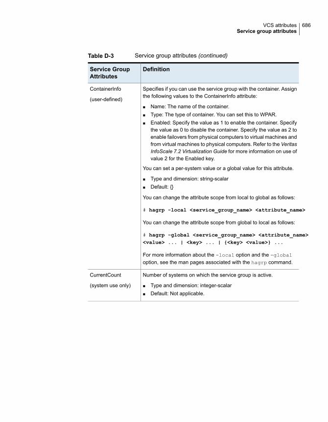
Table D-3 Service group attributes (continued)
DefinitionService GroupAttributes
Specifies if you can use the service group with the container. Assignthe following values to the ContainerInfo attribute:
■ Name: The name of the container.■ Type: The type of container. You can set this to WPAR.■ Enabled: Specify the value as 1 to enable the container. Specify
the value as 0 to disable the container. Specify the value as 2 toenable failovers from physical computers to virtual machines andfrom virtual machines to physical computers. Refer to the VeritasInfoScale 7.2 Virtualization Guide for more information on use ofvalue 2 for the Enabled key.
You can set a per-system value or a global value for this attribute.
■ Type and dimension: string-scalar■ Default: {}
You can change the attribute scope from local to global as follows:
# hagrp -local <service_group_name> <attribute_name>
You can change the attribute scope from global to local as follows:
# hagrp -global <service_group_name> <attribute_name><value> ... | <key> ... | {<key> <value>} ...
For more information about the -local option and the -globaloption, see the man pages associated with the hagrp command.
ContainerInfo
(user-defined)
Number of systems on which the service group is active.
■ Type and dimension: integer-scalar■ Default: Not applicable.
CurrentCount
(system use only)
686VCS attributesService group attributes

Table D-3 Service group attributes (continued)
DefinitionService GroupAttributes
Suppresses fault and failover messages, for a group and itsresources, from getting logged in the VCS engine log file. Thisattribute does not suppress the information messages getting loggedin the log file.
The attribute can take the following values:
■ 0 - Logs all the fault and failover messages for the service groupand its resources.
■ 1 - Disables the fault and failover messages of the service groups,but continues to log resource messages.
■ 2 - Disables the fault and failover messages of the service groupresources, but continues to log service group messages.
■ 3 - Disables the fault and failover messages of both servicegroups and its resources.
DisableFaultMessages
(user-defined)
Indicates whether HAD defers the auto-start of a global group in thelocal cluster in case the global cluster is not fully connected.
■ Type and dimension: boolean-scalar■ Default: Not applicable
DeferAutoStart
(system use only)
Indicates if a service group can be failed over or brought online.
The attribute can have global or local scope. If you define local(system-specific) scope for this attribute, VCS prevents the servicegroup from coming online on specified systems that have a value of0 for the attribute. You can use this attribute to prevent failovers ona system when performing maintenance on the system.
■ Type and dimension: boolean-scalar■ Default: 1 (enabled)
Enabled
(user-defined)
Indicates if VCS initiates an automatic failover when user issueshastop -local -evacuate.
■ Type and dimension: boolean-scalar■ Default: 1
Evacuate
(user-defined)
Indicates the node ID from which the service group is beingevacuated.
■ Type and dimension: integer-scalar■ Default: Not applicable
Evacuating
(system use only)
687VCS attributesService group attributes

Table D-3 Service group attributes (continued)
DefinitionService GroupAttributes
Contains list of pairs of low priority service groups and the systemson which they will be evacuated.
For example:
Grp1 EvacList grp2 Sys0 grp3 Sys0 grp4 Sys4
Type and dimension: string-association
Default: Not applicable.
EvacList
(system use only)
Displays the name of the high priority service group for whichevacuation is in progress. The service group name is visible only aslong as the evacuation is in progress.
Type and dimension: string-scalar
Default: Not applicable.
EvacuatingForGroup
(system use only)
Indicates service group is in the process of failing over.
■ Type and dimension: boolean-scalar■ Default: Not applicable
Failover
(system use only)
688VCS attributesService group attributes

Table D-3 Service group attributes (continued)
DefinitionService GroupAttributes
Defines the failover policy used by VCS to determine the system towhich a group fails over. It is also used to determine the system onwhich a service group has been brought online through manualoperation.
The policy is defined only for clusters that contain multiple systems:
Priority—The system defined as the lowest priority in the SystemListattribute is chosen.
Load—The system with the highest value of AvailableCapacity ischosen.
RoundRobin—Systems are chosen based on the active servicegroups they host. The system with the least number of active servicegroups is chosen first.
BiggestAvailable—Systems are chosen based on the forecastedavailable capacity for all systems in the SystemList. The system withthe highest available capacity forecasted is selected.
Note: VCS selects the node in an alphabetical order when VCSdetects two systems with same values set for the policy Priority,Load, RoundRobin, or BiggestAvailable.
Prerequisites for setting FailOverPolicy to BiggestAvailable:
■ The cluster attribute Statistics must be set to Enabled.■ Veritas recommends that the cluster attribute HostMeters should
contain at least one key.■ The service group attribute Load must contain at least one key.■ You cannot change the attribute from BiggestAvailable to some
other value, when the service group attribute CapacityReservedis set to 1 because the VCS engine reserves system capacitywhen it determines BiggestAvailable for the service group.When the service group online transition completes and after thenext forecast cycle, CapacityReserved is reset.
■ Type and dimension: string-scalar■ Default: Priority
FailOverPolicy
(user-defined)
689VCS attributesService group attributes

Table D-3 Service group attributes (continued)
DefinitionService GroupAttributes
Specifies if VCS should propagate the fault up to parent resourcesand take the entire service group offline when a resource faults.
The value 1 indicates that when a resource faults, VCS fails over theservice group, if the group’s AutoFailOver attribute is set to 1. If Thevalue 0 indicates that when a resource faults, VCS does not takeother resources offline, regardless of the value of the Critical attribute.The service group does not fail over on resource fault.
■ Type and dimension: boolean-scalar■ Default: 1
FaultPropagation
(user-defined)
Indicates the system name from which the service group is failingover. This attribute is specified when service group failover is a directconsequence of the group event, such as a resource fault within thegroup or a group switch.
■ Type and dimension: string-association■ Default: Not applicable
FromQ
(system use only)
Disables all actions, including autostart, online and offline, andfailover, except for monitor actions performed by agents. (Thisconvention is observed by all agents supplied with VCS.)
■ Type and dimension: boolean-scalar■ Default: 0 (not frozen)
Frozen
(system use only)
This attribute is used for VCS email notification and logging. VCSsends email notification to the person designated in this attributewhen events occur that are related to the service group. Note thatwhile VCS logs most events, not all events trigger notifications.
Make sure to set the severity level at which you want notifications tobe sent to GroupOwner or to at least one recipient defined in theSmtpRecipients attribute of the NotifierMngr agent.
■ Type and dimension: string-scalar■ Default: ""
GroupOwner
(user-defined)
690VCS attributesService group attributes

Table D-3 Service group attributes (continued)
DefinitionService GroupAttributes
This attribute is used for VCS email notification. VCS sends emailnotification to persons designated in this attribute when events relatedto the service group occur and when the event's severity level isequal to or greater than the level specified in the attribute.
Make sure to set the severity level at which you want notifications tobe sent to GroupRecipients or to at least one recipient defined in theSmtpRecipients attribute of the NotifierMngr agent.
■ Type and dimension: string-association■ email id: The email address of the person registered as a recipient
for notification.severity: The minimum level of severity at which notifications mustbe sent.
GroupRecipients
(user-defined)
List of operating system user accounts that have Guest privilegeson the service group.
This attribute applies to clusters running in secure mode.
■ Type and dimension: string-keylist■ Default: ""
Guests
(user-defined)
Indicates whether to keep service groups online or offline.
VCS sets this attribute to 1 if an attempt has been made to bring theservice group online.
For failover groups, VCS sets this attribute to 0 when the group istaken offline.
For parallel groups, it is set to 0 for the system when the group istaken offline or when the group faults and can fail over to anothersystem.
VCS sets this attribute to 2 for service groups if VCS attempts toautostart a service group; for example, attempting to bring a servicegroup online on a system from AutoStartList.
■ Type and dimension: integer-scalar■ Default: Not applicable.
IntentOnline
(system use only)
691VCS attributesService group attributes

Table D-3 Service group attributes (continued)
DefinitionService GroupAttributes
Lists the nodes where a resource that can be intentionally broughtonline is found ONLINE at first probe. IntentionalOnlineList is usedalong with AutoStartList to determine the node on which the servicegroup should go online when a cluster starts.
■ Type and dimension: string-keylist■ Default: Not applicable
IntentionalOnlineList
(system use only)
Indicates the time when service group was last brought online.
■ Type and dimension: integer-scalar■ Default: Not applicable
LastSuccess
(system use only)
Indicates the multidimensional value expressing load exerted by aservice group on the system.
When the cluster attribute Statistics is enabled, the allowed keyvalues are CPU, Mem, and Swap. The value for these keys incorresponding units as specified in MeterUnit (cluster attribute).
When the cluster attribute Statistics is not enabled, the allowed keyvalue is Units.
■ Type and dimension: float-association■ Default: Not applicable
The following additional considerations apply:
■ You cannot change this attribute when the service group attributeCapacityReserved is set to 1 in the cluster and when theFailOverPolicy is set to BiggestAvailable. This is because theVCS engine reserves system capacity based on the service groupattribute Load.When the service group's online transition completes and afterthe next forecast cycle, CapacityReserved is reset.
■ If the FailOverPolicy is set to BiggestAvailable for a service group,the attribute Load must be specified with at least one of thefollowing keys:■ CPU■ Mem■ Swap
Load
(user-defined)
692VCS attributesService group attributes

Table D-3 Service group attributes (continued)
DefinitionService GroupAttributes
Specifies if VCS manages resource failures within the service groupby calling the Clean function for the resources. This attribute cantake the following values.
NONE—VCS does not call the Clean function for any resource inthe group. You must manually handle resource faults.
See “ About controlling Clean behavior on resource faults”on page 335.
■ Type and dimension: string-scalar■ Default: ALL
ManageFaults
(user-defined)
Indicates if manual operations are allowed on the service group.
■ Type and dimension: boolean-scalar■ Default = 1 (enabled)
ManualOps
(user-defined)
Represents the weight given for the cluster attribute’s HostMeterskey to determine a target system for a service group when more thanone system meets the group attribute’s Load requirements.
■ Type and dimension: integer-association■ Default: Not applicable
Additional considerations for configuring this attribute in main.cf orchanging it at run time:
■ This is an optional service group attribute. If it is not defined fora group, the VCS considers the cluster attribute MeterWeight.
■ To override this attribute at an individual group level, define it atrun time or in the main.cf file. Ensure that keys are subsets of thecluster attribute HostAvailableMeters.
■ You cannot change this attribute when the service group attributeCapacityReserved is set to 1 in the cluster.
■ The values for the keys represent weights of the correspondingparameters. It should be in range of 0 to 10.
MeterWeight
(user-defined)
Indicates the system from which the service group is migrating. Thisattribute is specified when group failover is an indirect consequence(in situations such as a system shutdown or another group faultsand is linked to this group).
■ Type and dimension: string-association■ Default: Not applicable
MigrateQ
(system use only)
693VCS attributesService group attributes

Table D-3 Service group attributes (continued)
DefinitionService GroupAttributes
Indicates the number of attempts made to bring a service grouponline. This attribute is used only if the attribute OnlineRetryLimit isset for the service group.
■ Type and dimension: integer-scalar■ Default: Not applicable
NumRetries
(system use only)
When a node or a service group is frozen, the OnlineAtUnfreezeattribute specifies how an offline service group reacts after it or anode is unfrozen.
■ Type and dimension: integer-scalar■ Default: Not applicable
OnlineAtUnfreeze
(system use only)
When this attribute is enabled for a service group and the servicegroup comes online or is detected online, VCS clears the faults onall online type parent groups, such as online local, online global, andonline remote.
■ Type and dimension: boolean-scalar■ Default: 0
For example, assume that both the parent group and the child groupfaulted and both cannot failover. Later, when VCS tries again to bringthe child group online and the group is brought online or detectedonline, the VCS engine clears the faults on the parent group, allowingVCS to restart the parent group too.
OnlineClearParent
Indicates the interval, in seconds, during which a service group thathas successfully restarted on the same system and faults againshould be failed over, even if the attribute OnlineRetryLimit isnon-zero. This prevents a group from continuously faulting andrestarting on the same system.
■ Type and dimension: integer-scalar■ Default: 0
OnlineRetryInterval
(user-defined)
If non-zero, specifies the number of times the VCS engine tries torestart a faulted service group on the same system on which thegroup faulted, before it gives up and tries to fail over the group toanother system.
■ Type and dimension: integer-scalar■ Default: 0
OnlineRetryLimit
(user-defined)
694VCS attributesService group attributes

Table D-3 Service group attributes (continued)
DefinitionService GroupAttributes
List of operating system user groups that have Operator privilegeson the service group. This attribute applies to clusters running insecure mode.
■ Type and dimension: string-keylist■ Default: ""
OperatorGroups
(user-defined)
List of VCS users with privileges to operate the group. A GroupOperator can only perform online/offline, and temporaryfreeze/unfreeze operations pertaining to a specific group.
See “About VCS user privileges and roles” on page 79.
■ Type and dimension: string-keylist■ Default: ""
Operators
(user-defined)
Indicates if service group is failover (0), parallel (1), or hybrid(2).
■ Type and dimension: integer-scalar■ Default: 0
Parallel
(user-defined)
Number of resources in path not yet taken offline. When this numberdrops to zero, the engine may take the entire service group offline ifcritical fault has occurred.
■ Type and dimension: integer-scalar■ Default: Not applicable
PathCount
(system use only)
Indicates whether ProPCV-enabled resources in a service group canbe brought online on a node outside VCS control.
■ Type and dimension: boolean-scalar■ Default: Not applicable
See “About preventing concurrency violation” on page 339.
PCVAllowOnline
(system use only)
695VCS attributesService group attributes

Table D-3 Service group attributes (continued)
DefinitionService GroupAttributes
Functions as a lock on service groups listed in the hagrp -online
-propagate command and hagrp -offline -propagate command:
■ Type and dimension: integer-scalar
When PolicyIntention is set to a non-zero value for the service groupsin dependency tree, this attribute protects the service groups fromany other operation. PolicyIntention can take three values.
■ The value 0 indicates that the service group is not part of thehagrp -online -propagate operation or the hagrp-offline -propagate operation.
■ The value 1 indicates that the service group is part of the hagrp-online -propagate operation.
■ The value 2 indicates that the service group is part of the hagrp-offline -propagate operation.
PolicyIntention
(system use only)
Indicates that the VCS engine should not bring online a service groupin response to a manual group online, group autostart, or groupfailover. The engine should instead run the PreOnline trigger.
You can set a local (per-system) value or a global value for thisattribute. A per-system value enables you to control the firing ofPreOnline triggers on specific nodes in the cluster.
■ Type and dimension: boolean-scalar■ Default: 0
You can change the attribute scope from local to global as follows:
# hagrp -local <service_group_name> <attribute_name>
You can change the attribute scope from global to local as follows:
# hagrp -global <service_group_name> <attribute_name><value> ... | <key> ... | {<key> <value>} ...
For more information about the -local option and the -globaloption, see the man pages associated with the hagrp command.
PreOnline
(user-defined)
Indicates that VCS engine invoked the preonline script; however, thescript has not yet returned with group online.
■ Type and dimension: integer-scalar■ Default: Not applicable
PreOnlining
(system use only)
696VCS attributesService group attributes
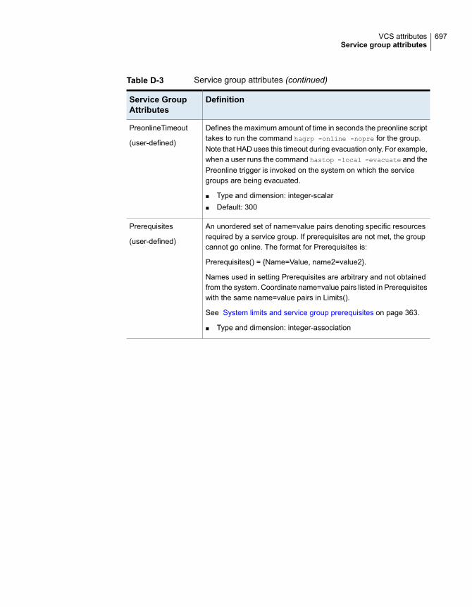
Table D-3 Service group attributes (continued)
DefinitionService GroupAttributes
Defines the maximum amount of time in seconds the preonline scripttakes to run the command hagrp -online -nopre for the group.Note that HAD uses this timeout during evacuation only. For example,when a user runs the command hastop -local -evacuate and thePreonline trigger is invoked on the system on which the servicegroups are being evacuated.
■ Type and dimension: integer-scalar■ Default: 300
PreonlineTimeout
(user-defined)
An unordered set of name=value pairs denoting specific resourcesrequired by a service group. If prerequisites are not met, the groupcannot go online. The format for Prerequisites is:
Prerequisites() = {Name=Value, name2=value2}.
Names used in setting Prerequisites are arbitrary and not obtainedfrom the system. Coordinate name=value pairs listed in Prerequisiteswith the same name=value pairs in Limits().
See System limits and service group prerequisites on page 363.
■ Type and dimension: integer-association
Prerequisites
(user-defined)
697VCS attributesService group attributes

Table D-3 Service group attributes (continued)
DefinitionService GroupAttributes
Indicates whether VCS engine should invoke PreSwitch actions inresponse to a manual service group switch operation.
Note: The engine does not invoke the PreSwitch action during agroup fault or when you use -any option to switch a group.
This attribute must be defined in the global group definition on theremote cluster. This attribute takes the following values:
0—VCS engine switches the service group normally.
1—VCS engine switches the service group based on the output ofPreSwitch action of the resources.
If you set the value as 1, the VCS engine looks for any resource inthe service group that supports PreSwitch action. If the action is notdefined for any resource, the VCS engine switches a service groupnormally.
If the action is defined for one or more resources, then the VCSengine invokes PreSwitch action for those resources. If all the actionssucceed, the engine switches the service group. If any of the actionsfail, the engine aborts the switch operation.
The engine invokes the PreSwitch action in parallel and waits for allthe actions to complete to decide whether to perform a switchoperation. The VCS engine reports the action’s output to the enginelog. The PreSwitch action does not change the configuration or thecluster state.
See “Administering global service groups in a global cluster setup”on page 513.
■ Type and dimension: boolean-scalar■ Default: 0
PreSwitch
(user-defined)
Indicates that the VCS engine invoked the agent’s PreSwitch action;however, the action is not yet complete.
■ Type and dimension: integer-scalar■ Default: Not applicable
PreSwitching
(system use only)
698VCS attributesService group attributes

Table D-3 Service group attributes (continued)
DefinitionService GroupAttributes
Indicates whether or not the resource dependency tree is written tothe configuration file. The value 1 indicates the tree is written.
Note: For very large configurations, the time taken to print the treeand to dump the configuration is high.
■ Type and dimension: boolean-scalar■ Default: 1
PrintTree
(user-defined)
Enables users to designate and prioritize the service group. VCSdoes not interpret the value; rather, this attribute enables the userto configure the priority of a service group and the sequence ofactions required in response to a particular event.
If the cluster-level attribute value for PreferredFencingPolicy is setto Group, VCS uses this Priority attribute value to calculate the nodeweight to determine the surviving subcluster during I/O fencing race.
VCS assigns the following node weight based on the priority of theservice group:
Priority Node weight1 6252 1253 254 50 or >=5 1
A higher node weight is associated with higher values of Priority.The node weight is the sum of node weight values for service groupswhich are ONLINE/PARTIAL.
See “About preferred fencing” on page 225.
■ Type and dimension: integer-scalar■ Default: 0
Priority
(user-defined)
Indicates whether all enabled resources in the group have beendetected by their respective agents.
■ Type and dimension: boolean-scalar■ Default: Not applicable
Probed
(system use only)
699VCS attributesService group attributes

Table D-3 Service group attributes (continued)
DefinitionService GroupAttributes
The number of resources that remain to be detected by the agenton each system.
■ Type and dimension: integer-scalar■ Default: Not applicable
ProbesPending
(system use only)
Indicates whether the service group is proactively prevented fromconcurrency violation for ProPCV-enabled resources.
■ Type and dimension: boolean-scalar■ Default: 0
See “About preventing concurrency violation” on page 339.
ProPCV
(user-defined)
Indicates VCS engine is responding to a failover event and is in theprocess of bringing the service group online or failing over the node.
■ Type and dimension: integer-scalar■ Default: Not applicable
Responding
(system use only)
For internal use only.
■ Type and dimension: integer-scalar■ Default: Not applicable
Restart
(system use only)
File from which the configuration is read. Do not configure thisattribute in main.cf.
Make sure the path exists on all nodes before running a commandthat configures this attribute.
Make sure the path exists on all nodes before configuring thisattribute.
■ Type and dimension: string-scalar■ Default: ./main.cf
SourceFile
(user-defined)
700VCS attributesService group attributes

Table D-3 Service group attributes (continued)
DefinitionService GroupAttributes
Group state on each system:
OFFLINE— All non-persistent resources are offline.
ONLINE —All resources whose AutoStart attribute is equal to 1 areonline.
FAULTED—At least one critical resource in the group is faulted oris affected by a fault.
PARTIAL—At least one, but not all, resources with Operations=OnOffis online, and not all AutoStart resources are online.
STARTING—Group is attempting to go online.
STOPPING— Group is attempting to go offline.
MIGRATING— Group is attempting to migrate a resource from thesource system to the target system. This state should be seen onlyas a combination of multiple states such as,ONLINE|STOPPING|MIGRATING,OFFLINE|STARTING|MIGRATING, and OFFLINE|MIGRATING.
A group state may be a combination of multiple states describedabove. For example, OFFLINE | FAULTED, OFFLINE | STARTING,PARTIAL | FAULTED, PARTIAL | STARTING, PARTIAL |STOPPING, ONLINE | STOPPING
■ Type and dimension: integer-scalar■ Default: Not applicable.
State
(system use only)
701VCS attributesService group attributes

Table D-3 Service group attributes (continued)
DefinitionService GroupAttributes
Determines whether a service group is autodisabled when the systemis down and if the service group is taken offline when the system isrebooted or is shut down gracefully.
If SysDownPolicy contains the key AutoDisableNoOffline, thefollowing conditions apply:
■ The service group is autodisabled when system is down,gracefully shut down, or is detected as down.
■ The service group is not taken offline when the system rebootsor shuts down gracefully.
Valid values: Empty keylist or the key AutoDisableNoOffline
Default: Empty keylist
For example, if a service group with SysDownPolicy =AutoDisableNoOffline is online on system sys1, it has the followingeffect for various commands:
■ The hastop -local -evacuate command for sys1 is rejected■ The hastop -sysoffline command is accepted but the
service group with SysDownPolicy = AutoDisableNoOffline is nottaken offline.
■ The hastop -all command is rejected.
SysDownPolicy
(user-defined)
List of systems on which the service group is configured to run andtheir priorities. Lower numbers indicate a preference for the systemas a failover target.
Note: You must define this attribute prior to setting the AutoStartListattribute.
■ Type and dimension: integer-association■ Default: "" (none)
SystemList
(user-defined)
702VCS attributesService group attributes

Table D-3 Service group attributes (continued)
DefinitionService GroupAttributes
Indicates the virtual sublists within the SystemList attribute that grantpriority in failing over. Values are string/integer pairs. The string keyis the name of a system in the SystemList attribute, and the integeris the number of the zone. Systems with the same zone number aremembers of the same zone. If a service group faults on one systemin a zone, it is granted priority to fail over to another system withinthe same zone, despite the policy granted by the FailOverPolicyattribute.
■ Type and dimension: integer-association■ Default: "" (none)
Note: You cannot modify this attribute when SiteAware is set as 1and Sites are defined.
SystemZones
(user-defined)
Identifies special-purpose service groups created for specific VCSproducts.
■ Type and dimension: string-scalar■ Default: Not applicable.
Tag
(user-defined)
Indicates the number of target systems on which the service groupshould be brought online.
■ Type and dimension: integer-scalar■ Default: Not applicable.
TargetCount
(system use only)
Indicates if service groups can be brought online or taken offline onnodes in the cluster. Service groups cannot be brought online ortaken offline if the value of the attribute is 1.
■ Type and dimension: boolean-scalar■ Default: 0 (not frozen)
TFrozen
(user-defined)
Indicates the node name to which the service is failing over. Thisattribute is specified when service group failover is a directconsequence of the group event, such as a resource fault within thegroup or a group switch.
■ Type and dimension: string-association■ Default: Not applicable
ToQ
(system use only)
703VCS attributesService group attributes

Table D-3 Service group attributes (continued)
DefinitionService GroupAttributes
For internal use only.
■ Type and dimension: boolean-scalar■ Default: Not applicable
TriggerEvent
(user-defined)
Enables you to customize the trigger path.
If a trigger is enabled but the trigger path is "" (default), VCS invokesthe trigger from the $VCS_HOME/bin/triggers directory. If you specifyan alternate directory, VCS invokes the trigger from that path. Thevalue is case-sensitive. VCS does not trim the leading spaces ortrailing spaces in the Trigger Path value. If the path contains leadingspaces or trailing spaces, the trigger might fail to get executed.
The path that you specify must be in the following format:
$VCS_HOME/TriggerPath/Trigger
For example, if TriggerPath is set to mytriggers/sg1, VCS looks forthe preonline trigger scripts in the$VCS_HOME/mytriggers/sg1/preonline/ directory.
■ Type and dimension: string-scalar■ Default: ""
TriggerPath
(user-defined)
Defines whether VCS invokes the resfault trigger when a resourcefaults. The value 0 indicates that VCS does not invoke the trigger.
■ Type and dimension: boolean-scalar■ Default: 1
TriggerResFault
(user-defined)
Determines whether or not to invoke the resrestart trigger if resourcerestarts.
See “About the resrestart event trigger” on page 430.
To invoke the resrestart trigger for a specific resource, enable thisattribute at the resource level.
See “Resource attributes” on page 655.
■ Type and dimension: boolean-scalar■ Default: 0 (disabled)
TriggerResRestart
(user-defined)
704VCS attributesService group attributes

Table D-3 Service group attributes (continued)
DefinitionService GroupAttributes
Determines whether or not to invoke the resstatechange trigger ifresource state changes.
See “About the resstatechange event trigger” on page 431.
To invoke the resstatechange trigger for a specific resource, enablethis attribute at the resource level.
See “Resource attributes” on page 655.
■ Type and dimension: boolean-scalar■ Default: 0 (disabled)
TriggerResStateChange
(user-defined)
Determines if a specific trigger is enabled or not.
Triggers are disabled by default. You can enable specific triggers onall nodes or on selected nodes. Valid values are VIOLATION,NOFAILOVER, PREONLINE, POSTONLINE, POSTOFFLINE,RESFAULT, RESSTATECHANGE, and RESRESTART.
To enable triggers on a node, add trigger keys in the following format:
TriggersEnabled@node1 = {POSTOFFLINE, POSTONLINE}
The postoffline trigger and postonline trigger are enabled on node1.
To enable triggers on all nodes in the cluster, add trigger keys in thefollowing format:
TriggersEnabled = {POSTOFFLINE, POSTONLINE}
The postoffline trigger and postonline trigger are enabled on all nodes.
■ Type and dimension: string-keylist■ Default: {}
You can change the attribute scope from local to global as follows:
# hagrp -local <service_group_name> <attribute_name>
You can change the attribute scope from global to local as follows:
# hagrp -global <service_group_name> <attribute_name><value> ... | <key> ... | {<key> <value>} ...
For more information about the -local option and the -globaloption, see the man pages associated with the hagrp command.
TriggersEnabled
(user-defined)
705VCS attributesService group attributes

Table D-3 Service group attributes (continued)
DefinitionService GroupAttributes
Creates a dependency (via an ordered list) between resource typesspecified in the service group list, and all instances of the respectiveresource type.
■ Type and dimension: string-keylist■ Default: ""
TypeDependencies
(user-defined)
Represents the total number of resources with pending online oroffline operations. This is a localized attribute.
■ Type and dimension: integer■ Default: 0
To list this attribute, use the -all option with the hagrp -displaycommand.
The hagrp -flush command resets this attribute.
UnSteadyCount
(system use only)
This is a free form string-association attribute to hold any key-valuepair. "Name" and "UITimeout" keys are reserved by VCS health view.You must not delete these keys or update the values correspondingto these keys, but you can add other keys and use it for any otherpurpose.
■ Type and dimension: string-association■ Default: {}
You can change the attribute scope from local to global as follows:
# hagrp -local <service_group_name> <attribute_name>
You can change the attribute scope from global to local as follows:
# hagrp -global <service_group_name> <attribute_name><value> ... | <key> ... | {<key> <value>} ...
For more information about the -local option and -global option,see the man pages associated with the hagrp command.
UserAssoc
(user-defined)
Use this attribute for any purpose. It is not used by VCS.
■ Type and dimension: integer-scalar■ Default: 0
UserIntGlobal
(user-defined)
706VCS attributesService group attributes
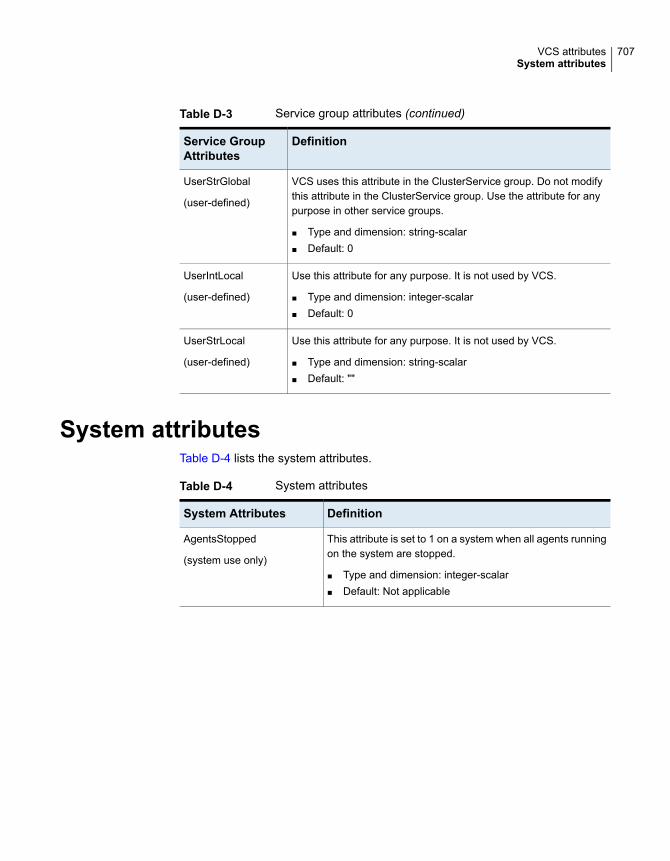
Table D-3 Service group attributes (continued)
DefinitionService GroupAttributes
VCS uses this attribute in the ClusterService group. Do not modifythis attribute in the ClusterService group. Use the attribute for anypurpose in other service groups.
■ Type and dimension: string-scalar■ Default: 0
UserStrGlobal
(user-defined)
Use this attribute for any purpose. It is not used by VCS.
■ Type and dimension: integer-scalar■ Default: 0
UserIntLocal
(user-defined)
Use this attribute for any purpose. It is not used by VCS.
■ Type and dimension: string-scalar■ Default: ""
UserStrLocal
(user-defined)
System attributesTable D-4 lists the system attributes.
Table D-4 System attributes
DefinitionSystem Attributes
This attribute is set to 1 on a system when all agents runningon the system are stopped.
■ Type and dimension: integer-scalar■ Default: Not applicable
AgentsStopped
(system use only)
707VCS attributesSystem attributes

Table D-4 System attributes (continued)
DefinitionSystem Attributes
Indicates the available capacity of the system.
The function of this attribute depends on the value of thecluster-level attribute Statistics. If the value of the Statisticsis:
■ Enabled—Any change made to AvailableCapacity doesnot affect VCS behavior.
■ MeteringOnly or Disabled—This attribute is populatedbased on Capacity and DynamicLoad (system attributes)and Load (service group attribute) specified using thehasys -load command. The key for this value is Units.
You cannot configure this attribute in the main.cf file.
■ Type and dimension: float-association■ Default: Not applicable
AvailableCapacity
(system use only)
708VCS attributesSystem attributes

Table D-4 System attributes (continued)
DefinitionSystem Attributes
Represents total capacity of a system. The possible valuesare:
■ Enabled—The attribute Capacity is auto-populated bymeters representing system capacity in absolute units. Ithas all the keys specified in HostMeters, such as CPU,Mem, and Swap. The values for keys are set incorresponding units as specified in the Cluster attributeMeterUnit.You cannot configure this attribute in the main.cf file if thecluster-level attribute Statistics is set to Enabled.If the cluster-level attribute Statistics is enabled, anychange made to Capacity does not affect VCS behavior.
■ MeteringOnly or Disabled—Allows you to define a valuefor Capacity if the value of the cluster-level attributeStatistics is set to MeteringOnly or Disabled. This valueis relative to other systems in the cluster and does notreflect any real value associated with a particular system.The key for this value is Units. The default value for thisattribute is 100 Units.For example, the administrator may assign a value of 200to a 16-processor system and 100 to an 8-processorsystem.You can configure this attribute in the main.cf file and alsomodify the value at run time if Statistics is set toMeteringOnly or Disabled.
■ Type and dimension: float-association■ Default: Depends on the value set for Statistics.
Capacity
(user-defined)
Number of 512-byte blocks in configuration when the systemjoined the cluster.
■ Type and dimension: integer-scalar■ Default: Not applicable
ConfigBlockCount
(system use only)
Sixteen-bit checksum of configuration identifying when thesystem joined the cluster.
■ Type and dimension: integer-scalar■ Default: Not applicable
ConfigCheckSum
(system use only)
709VCS attributesSystem attributes

Table D-4 System attributes (continued)
DefinitionSystem Attributes
State of configuration on the disk when the system joined thecluster.
■ Type and dimension: integer-scalar■ Default: Not applicable
ConfigDiskState
(system use only)
Directory containing the configuration files.
■ Type and dimension: string-scalar■ Default: "/etc/VRTSvcs/conf/config"
ConfigFile
(system use only)
The count of outstanding CONFIG_INFO messages the localnode expects from a new membership message. Thisattribute is non-zero for the brief period during which newmembership is processed. When the value returns to 0, thestate of all nodes in the cluster is determined.
■ Type and dimension: integer-scalar■ Default: Not applicable
ConfigInfoCnt
(system use only)
Last modification date of configuration when the system joinedthe cluster.
■ Type and dimension: integer-scalar■ Default: Not applicable
ConfigModDate
(system use only)
Binds HAD to a particular logical processor ID depending onthe value of BindTo and CPUNumber. Interrupts are disabledon the logical processor that HAD binds to.
■ Type and dimension: string-association■ Default: BindTo = NONE, CPUNumber = 0
CPUNumber specifies the logical processor ID to which HADbinds. CPUNumber is used only when BindTo is specifiedas CPUNUM.
BindTo can take one of the following values:
■ NONE: HAD is not bound to any logical processor ID.■ ANY: HAD is pinned to a logical processor ID till it is in
RUNNING state or BindTo is changed.■ CPUNUM: HAD is pinned to the logical processor ID
specified by CPUNumber.
CPUBinding
710VCS attributesSystem attributes

Table D-4 System attributes (continued)
DefinitionSystem Attributes
Determines the threshold values for CPU utilization basedon which various levels of logs are generated. The notificationlevels are Critical, Warning, Note, and Info, and the logs arestored in the file engine_A.log. If the Warning level is crossed,a notification is generated. The values are configurable at asystem level in the cluster.
■ For example, the administrator may set the value ofCPUThresholdLevel as follows:
■ CPUThresholdLevel={Critical=95, Warning=80, Note=75,Info=60}
■ Type and dimension: integer-association■ Default: Critical=90, Warning=80, Note=70, Info=60
CPUThresholdLevel
(user-defined)
This attribute is deprecated. VCS monitors system resourceson startup.
CPUUsage
(system use only)
This attribute is deprecated. VCS monitors system resourceson startup.
CPUUsageMonitoring
System-maintained calculation of current value of Limits.
CurrentLimits = Limits - (additive value of all service groupPrerequisites).
■ Type and dimension: integer-association■ Default: Not applicable
CurrentLimits
(system use only)
Deprecated attribute. Indicates status of communication diskson any system.
■ Type and dimension: string-association■ Default: Not applicable
DiskHbStatus
(system use only)
System-maintained value of current dynamic load. The valueis set external to VCS with the hasys -load command. Whenyou specify the dynamic system load, VCS does not use thestatic group load.
■ Type and dimension: float-association■ Default: "" (none)
DynamicLoad
(user-defined)
711VCS attributesSystem attributes

Table D-4 System attributes (continued)
DefinitionSystem Attributes
Indicates whether the VCS engine (HAD) was restarted bythe hashadow process on a node in the cluster. The value 1indicates that the engine was restarted; 0 indicates it was notrestarted.
■ Type and dimension: boolean-scalar■ Default: 0
EngineRestarted
(system use only)
Specifies the major, minor, maintenance-patch, andpoint-patch version of VCS.
The value of EngineVersion attribute is in hexa-decimalformat. To retrieve version information:
Major Version: EngineVersion >> 24 & 0xffMinor Version: EngineVersion >> 16 & 0xffMaint Patch: EngineVersion >> 8 & 0xffPoint Patch: EngineVersion & 0xff
■ Type and dimension: integer-scalar■ Default: Not applicable
EngineVersion
(system use only)
Indicates the system priority for preferred fencing. This valueis relative to other systems in the cluster and does not reflectany real value associated with a particular system.
If the cluster-level attribute value for PreferredFencingPolicyis set to System, VCS uses this FencingWeight attribute todetermine the node weight to ascertain the survivingsubcluster during I/O fencing race.
See “About preferred fencing” on page 225.
■ Type and dimension: integer-scalar■ Default: 0
FencingWeight
(user-defined)
Indicates if service groups can be brought online on thesystem. Groups cannot be brought online if the attribute valueis 1.
■ Type and dimension: boolean-scalar■ Default: 0
Frozen
(system use only)
712VCS attributesSystem attributes

Table D-4 System attributes (continued)
DefinitionSystem Attributes
Determines the local IP address that VCS uses to acceptconnections. Incoming connections over other IP addressesare dropped. If GUIIPAddr is not set, the default behavior isto accept external connections over all configured local IPaddresses.
See “User privileges for CLI commands” on page 81.
■ Type and dimension: string-scalar■ Default: ""
GUIIPAddr
(user-defined)
Indicates the forecasted available capacities of the systemsin a cluster based on the past metered AvailableCapacity.
The HostMonitor agent auto-populates values for thisattribute, if the cluster attribute Statistics is set to Enabled. Ithas all the keys specified in HostMeters, such as CPU, Mem,and Swap. The values for keys are set in corresponding unitsas specified in the Cluster attribute MeterUnit.
You cannot configure this attribute in main.cf.
■ Type and dimension: float-association■ Default: Not applicable
HostAvailableForecast
(system use only)
List of host resources that the HostMonitor agent monitors.The values of keys such as Mem and Swap are measuredin MB or GB, and CPU is measured in MHz or GHz.
■ Type and dimension: string-keylist■ Default: { CPU, Mem, Swap }
HostMonitor
(system use only)
Indicates the percentage usage of the resources on the hostas computed by the HostMonitor agent. This attributepopulates all parameters specified in the cluster attributeHostMeters if Statistics is set to MeterHostOnly or Enabled.
■ Type and dimension: integer-association■ Default: Not applicable
HostUtilization
(system use only)
713VCS attributesSystem attributes

Table D-4 System attributes (continued)
DefinitionSystem Attributes
Indicates the license type of the base VCS key used by thesystem. Possible values are:
0—DEMO
1—PERMANENT
2—PERMANENT_NODE_LOCK
3—DEMO_NODE_LOCK
4—NFR
5—DEMO_EXTENSION
6—NFR_NODE_LOCK
7—DEMO_EXTENSION_NODE_LOCK
■ Type and dimension: integer-scalar■ Default: Not applicable
LicenseType
(system use only)
An unordered set of name=value pairs denoting specificresources available on a system. Names are arbitrary andare set by the administrator for any value. Names are notobtained from the system.
The format for Limits is: Limits = { Name=Value,Name2=Value2}.
■ Type and dimension: integer-association■ Default: ""
Limits
(user-defined)
Indicates status of private network links on any system.
Possible values include the following:
LinkHbStatus = { nic1 = UP, nic2 = DOWN }
Where the value UP for nic1means there is at least one peerin the cluster that is visible on nic1.
Where the value DOWN for nic2means no peer in the clusteris visible on nic2.
■ Type and dimension: string-association■ Default: Not applicable
LinkHbStatus
(system use only)
714VCS attributesSystem attributes

Table D-4 System attributes (continued)
DefinitionSystem Attributes
Displays the node ID defined in the file.
/etc/llttab.
■ Type and dimension: integer-scalar■ Default: Not applicable
LLTNodeId
(system use only)
System-maintained internal counter of how many secondsthe system load has been above LoadWarningLevel. Thisvalue resets to zero anytime system load drops below thevalue in LoadWarningLevel.
If the cluster-level attribute Statistics is enabled, any changemade to LoadTimeCounter does not affect VCS behavior.
■ Type and dimension: integer-scalar■ Default: Not applicable
LoadTimeCounter
(system use only)
How long the system load must remain at or aboveLoadWarningLevel before the LoadWarning trigger is fired.If set to 0 overload calculations are disabled.
If the cluster-level attribute Statistics is enabled, any changemade to LoadTimeThreshold does not affect VCS behavior.
■ Type and dimension: integer-scalar■ Default: 600
LoadTimeThreshold
(user-defined)
A percentage of total capacity where load has reached acritical limit. If set to 0 overload calculations are disabled.
For example, setting LoadWarningLevel = 80 sets the warninglevel to 80 percent.
The value of this attribute can be set from 1 to 100. If set to1, system load must equal 1 percent of system capacity tobegin incrementing the LoadTimeCounter. If set to 100,system load must equal system capacity to increment theLoadTimeCounter.
If the cluster-level attribute Statistics is enabled, any changemade to LoadWarningLevel does not affect VCS behavior.
■ Type and dimension: integer-scalar■ Default: 80
LoadWarningLevel
(user-defined)
715VCS attributesSystem attributes

Table D-4 System attributes (continued)
DefinitionSystem Attributes
Determines the threshold values for memory utilization basedon which various levels of logs are generated. The notificationlevels are Critical, Warning, Note, and Info, and the logs arestored in the file engine_A.log. If the Warning level is crossed,a notification is generated. The values are configurable at asystem level in the cluster.
For example, the administrator may set the value ofMemThresholdLevel as follows:
■ MemThresholdLevel={Critical=95, Warning=80, Note=75,Info=60}
■ Type and dimension: integer-association■ Default: Critical=90, Warning=80, Note=70, Info=60
MemThresholdLevel
(user-defined)
716VCS attributesSystem attributes

Table D-4 System attributes (continued)
DefinitionSystem Attributes
Acts as an internal system attribute with predefined keys.This attribute is updated only when the Cluster attributeAdpativePolicy is set to Enabled.
■ Type and dimension: integer-association■ Default: Not applicable
Possible keys are:
■ AvailableGC: Stores the value of the cluster attributeGlobalCounter when the HostMonitor agent updates thesystem attribute AvailableCapacity.If the value of AvailableGC for a system in running stateis older than the last 24 values of the cluster attributeGlobalCounter it indicates:■ Values are not updated at the required frequency by
the HostMonitor agent.■ Values of system attributes AvailableCapacity and
HostUtilization are stale.■ ForecastGC: Stores cluster attribute GlobalCounter value
when system HostAvailableForecast attribute is updated.If the value of ForecastGC for a system in running stateis older than the last 72 values of the cluster attributeGlobalCounter it indicates :■ HostMonitor agent is not forecasting the available
capacity at the required frequency.■ The values of the system attribute
HostAvailableForecast are stale.■ If any of the running systems in SystemList have stale
value in HostAvailableForecast when FailOverPolicyis set to BiggestAvailable, then VCS does not applyBiggestAvailable policy. Instead, it considers Priorityas the FailOverPolicy.
MeterRecord
(system use only)
When set to 0, this attribute autodisables service groupswhen the VCS engine is taken down. Groups remainautodisabled until the engine is brought up (regularmembership).
This attribute’s value is updated whenever a node joins (getsinto RUNNING state) or leaves the cluster. This attributecannot be set manually.
■ Type and dimension: boolean-scalar■ Default: 0
NoAutoDisable
(system use only)
717VCS attributesSystem attributes

Table D-4 System attributes (continued)
DefinitionSystem Attributes
System (node) identification specified in:
/etc/llttab.
■ Type and dimension: integer-scalar■ Default: Not applicable
NodeId
(system use only)
Number of groups that are online, or about to go online, ona system.
■ Type and dimension: integer-scalar■ Default: Not applicable
OnGrpCnt
(system use only)
Indicates the name of the physical system on which the VMis running when VCS is deployed on a VM.
■ Type and dimension: string-scalar■ Default: Not applicable
PhysicalServer
(system use only)
Indicates the reserved capacity on the systems for servicegroups which are coming online and with FailOverPolicy isset to BiggestAvailable. It has all of the keys specified inHostMeters, such as CPU, Mem, and Swap. The values forkeys are set in corresponding units as specified in the Clusterattribute MeterUnit.
■ Type and dimension: float-association■ Default: Not applicable
When the service group completes online transition and afterthe next forecast cycle, ReservedCapacity is updated.
You cannot configure this attribute in main.cf.
ReservedCapacity
(system use only)
718VCS attributesSystem attributes
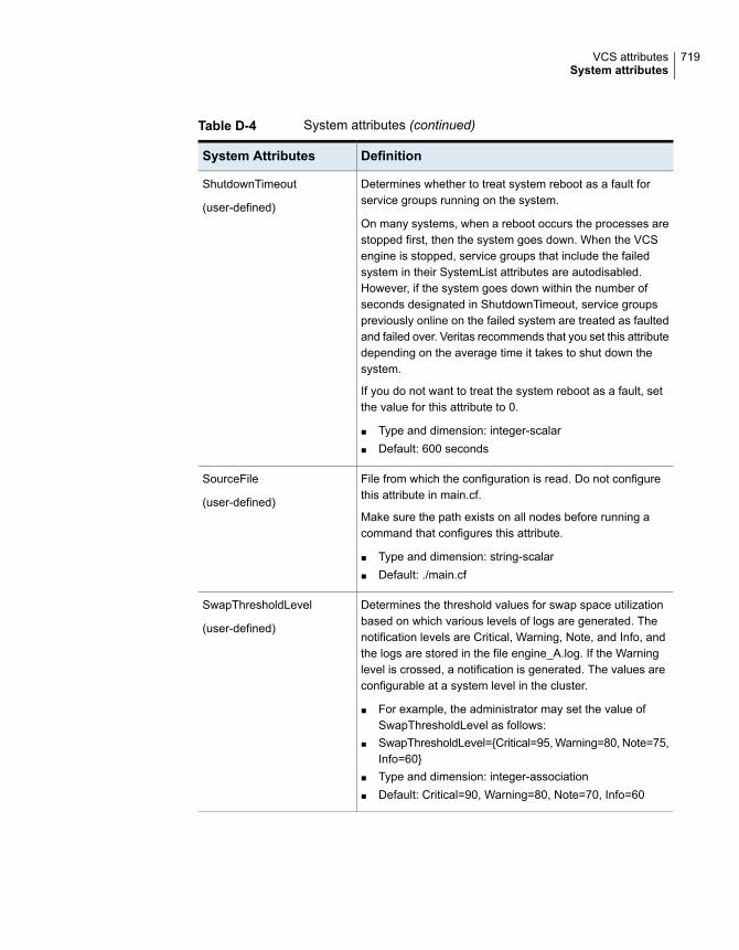
Table D-4 System attributes (continued)
DefinitionSystem Attributes
Determines whether to treat system reboot as a fault forservice groups running on the system.
On many systems, when a reboot occurs the processes arestopped first, then the system goes down. When the VCSengine is stopped, service groups that include the failedsystem in their SystemList attributes are autodisabled.However, if the system goes down within the number ofseconds designated in ShutdownTimeout, service groupspreviously online on the failed system are treated as faultedand failed over. Veritas recommends that you set this attributedepending on the average time it takes to shut down thesystem.
If you do not want to treat the system reboot as a fault, setthe value for this attribute to 0.
■ Type and dimension: integer-scalar■ Default: 600 seconds
ShutdownTimeout
(user-defined)
File from which the configuration is read. Do not configurethis attribute in main.cf.
Make sure the path exists on all nodes before running acommand that configures this attribute.
■ Type and dimension: string-scalar■ Default: ./main.cf
SourceFile
(user-defined)
Determines the threshold values for swap space utilizationbased on which various levels of logs are generated. Thenotification levels are Critical, Warning, Note, and Info, andthe logs are stored in the file engine_A.log. If the Warninglevel is crossed, a notification is generated. The values areconfigurable at a system level in the cluster.
■ For example, the administrator may set the value ofSwapThresholdLevel as follows:
■ SwapThresholdLevel={Critical=95, Warning=80, Note=75,Info=60}
■ Type and dimension: integer-association■ Default: Critical=90, Warning=80, Note=70, Info=60
SwapThresholdLevel
(user-defined)
719VCS attributesSystem attributes

Table D-4 System attributes (continued)
DefinitionSystem Attributes
Provides platform-specific information, including the name,version, and release of the operating system, the name ofthe system on which it is running, and the hardware type.
■ Type and dimension: string-scalar■ Default: Not applicable
SysInfo
(system use only)
Indicates the system name.
■ Type and dimension: string-scalar■ Default: Not applicable
SysName
(system use only)
Indicates system states, such as RUNNING, FAULTED,EXITED, etc.
■ Type and dimension: integer-scalar■ Default: Not applicable
SysState
(system use only)
Indicates the location of the system.
■ Type and dimension: string-scalar■ Default: ""
SystemLocation
(user-defined)
Use this attribute for VCS email notification and logging. VCSsends email notification to the person designated in thisattribute when an event occurs related to the system. Notethat while VCS logs most events, not all events triggernotifications.
Make sure to set the severity level at which you wantnotifications to SystemOwner or to at least one recipientdefined in the SmtpRecipients attribute of the NotifierMngragent.
■ Type and dimension: string-scalar■ Default: ""■ Example: "unknown"
SystemOwner
(user-defined)
720VCS attributesSystem attributes

Table D-4 System attributes (continued)
DefinitionSystem Attributes
This attribute is used for VCS email notification. VCS sendsemail notification to persons designated in this attribute whenevents related to the system occur and when the event'sseverity level is equal to or greater than the level specifiedin the attribute.
Make sure to set the severity level at which you wantnotifications to be sent to SystemRecipients or to at least onerecipient defined in the SmtpRecipients attribute of theNotifierMngr agent.
■ Type and dimension: string-association■ email id: The e-mail address of the person registered as
a recipient for notification.severity: The minimum level of severity at whichnotifications must be sent.
SystemRecipients
(user-defined)
Indicates whether a service group can be brought online ona node. Service group cannot be brought online if the valueof this attribute is 1.
■ Type and dimension: boolean-scalar■ Default: 0
TFrozen
(user-defined)
Indicates in seconds the time to Regular State Exit. Time iscalculated as the duration between the events of VCS losingport h membership and of VCS losing port a membership ofGAB.
■ Type and dimension: integer-scalar■ Default: Not applicable
TRSE
(system use only)
This attribute has four values:
Down (0): System is powered off, or GAB and LLT are notrunning on the system.
Up but not in cluster membership (1): GAB and LLT arerunning but the VCS engine is not.
Up and in jeopardy (2): The system is up and part of clustermembership, but only one network link (LLT) remains.
Up (3): The system is up and part of cluster membership,and has at least two links to the cluster.
■ Type and dimension: integer-scalar■ Default: Not applicable
UpDownState
(system use only)
721VCS attributesSystem attributes

Table D-4 System attributes (continued)
DefinitionSystem Attributes
Stores integer values you want to use. VCS does not interpretthe value of this attribute.
■ Type and dimension: integer-scalar■ Default: 0
UserInt
(user-defined)
Indicates which VCS features are enabled. Possible valuesare:
0—No features enabled (VCS Simulator)
1—L3+ is enabled
2—Global Cluster Option is enabled
Even though VCSFeatures attribute is an integer attribute,when you query the value with the hasys -value commandor the hasys -display command, it displays as the stringL10N for value 1 and DR for value 2.
■ Type and dimension: integer-scalar■ Default: Not applicable
VCSFeatures
(system use only)
Cluster attributesTable D-5 lists the cluster attributes.
Table D-5 Cluster attributes
DefinitionCluster Attributes
List of operating system user account groups that have administrative privileges onthe cluster. This attribute applies to clusters running in secure mode.
■ Type and dimension: string-keylist■ Default: ""
AdministratorGroups
(user-defined)
Contains list of users with Administrator privileges.
■ Type and dimension: string-keylist■ Default: ""
Administrators
(user-defined)
Lists the service groups scheduled to be auto-cleared. It also indicates the time atwhich the auto-clear for the group will be performed.
AutoClearQ
(System use only)
722VCS attributesCluster attributes

Table D-5 Cluster attributes (continued)
DefinitionCluster Attributes
If the local cluster cannot communicate with one or more remote clusters, this attributespecifies the number of seconds the VCS engine waits before initiating the AutoStartprocess for an AutoStart global service group.
■ Type and dimension: integer-scalar■ Default: 150 seconds
AutoStartTimeout
(user-defined)
Indicates whether the newly joined or added systems in cluster become part of theSystemList of the ClusterService service group if the service group is configured. Thevalue 1 (default) indicates that the new systems are added to SystemList ofClusterService. The value 0 indicates that the new systems are not added to SystemListof ClusterService.
■ Type and dimension: integer-scalar■ Default: 1
AutoAddSystemtoCSG
(user-defined)
Time period in minutes after which VCS backs up the configuration files if theconfiguration is in read-write mode.
The value 0 indicates VCS does not back up configuration files. Set this attribute toat least 3.
See “Scheduling automatic backups for VCS configuration files” on page 109.
■ Type and dimension: integer-scalar■ Default: 0
BackupInterval
(user-defined)
723VCS attributesCluster attributes

Table D-5 Cluster attributes (continued)
DefinitionCluster Attributes
The CID provides universally unique identification for a cluster.
VCS populates this attribute once the engine passes an hacf-generated snapshot toit. This happens when VCS is about to go to a RUNNING state from the LOCAL_BUILDstate.
Once VCS receives the snapshot from the engine, it reads the file/etc/vx/.uuids/clusuuid file. VCS uses the file’s contents as the value for the CIDattribute. The clusuuid file’s first line must not be empty. If the file does not exists oris empty VCS then exits gracefully and throws an error.
A node that joins a cluster in the RUNNING state receives the CID attribute as partof the REMOTE_BUILD snapshot. Once the node has joined completely, it receivesthe snapshot. The node reads the file /etc/vx/.uuids/clusuuid to compare the valuethat it received from the snapshot with value that is present in the file. If the value doesnot match or if the file does not exist, the joining node exits gracefully and does notjoin the cluster.
To populate the /etc/vx/.uuids/clusuuid file, run the /opt/VRTSvcs/bin/uuidconfig.plutility.
See “Configuring and unconfiguring the cluster UUID value” on page 155.
You cannot change the value of this attribute with the haclus –modify command.
■ Type and dimension: string-scalar■ Default: ""
CID
(system defined)
Indicates the current state of the cluster.
■ Type and dimension: integer-scalar■ Default: Not applicable.
ClusState
(system use only)
Specifies the cluster’s virtual IP address (used by a remote cluster when connectingto the local cluster).
■ Type and dimension: string-scalar■ Default: ""
ClusterAddress
(user-defined)
Specifies the location of the cluster.
■ Type and dimension: string-scalar■ Default: ""
ClusterLocation
(user-defined)
The name of cluster.
■ Type and dimension: string-scalar■ Default: ""
ClusterName
(user-defined)
724VCS attributesCluster attributes
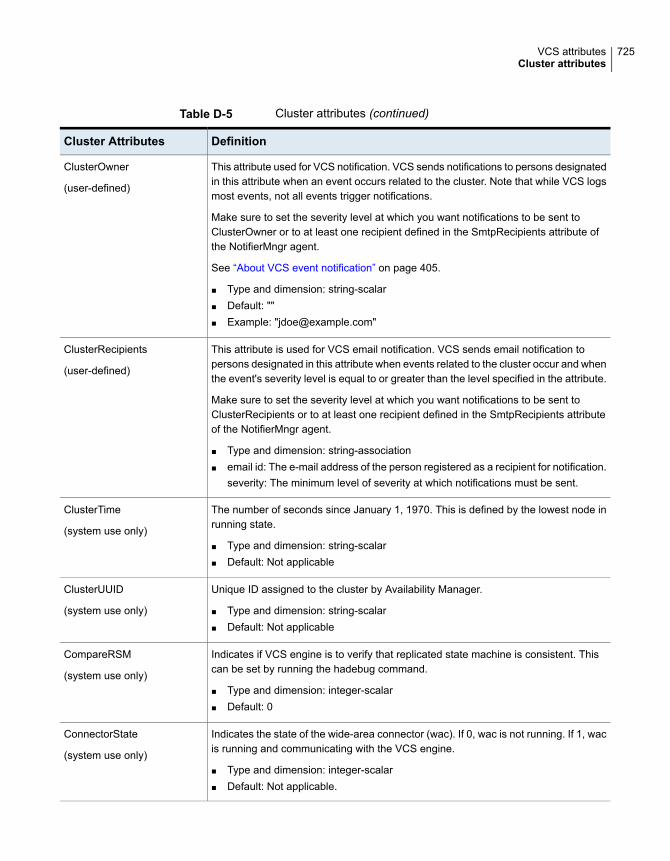
Table D-5 Cluster attributes (continued)
DefinitionCluster Attributes
This attribute used for VCS notification. VCS sends notifications to persons designatedin this attribute when an event occurs related to the cluster. Note that while VCS logsmost events, not all events trigger notifications.
Make sure to set the severity level at which you want notifications to be sent toClusterOwner or to at least one recipient defined in the SmtpRecipients attribute ofthe NotifierMngr agent.
See “About VCS event notification” on page 405.
■ Type and dimension: string-scalar■ Default: ""■ Example: "[email protected]"
ClusterOwner
(user-defined)
This attribute is used for VCS email notification. VCS sends email notification topersons designated in this attribute when events related to the cluster occur and whenthe event's severity level is equal to or greater than the level specified in the attribute.
Make sure to set the severity level at which you want notifications to be sent toClusterRecipients or to at least one recipient defined in the SmtpRecipients attributeof the NotifierMngr agent.
■ Type and dimension: string-association■ email id: The e-mail address of the person registered as a recipient for notification.
severity: The minimum level of severity at which notifications must be sent.
ClusterRecipients
(user-defined)
The number of seconds since January 1, 1970. This is defined by the lowest node inrunning state.
■ Type and dimension: string-scalar■ Default: Not applicable
ClusterTime
(system use only)
Unique ID assigned to the cluster by Availability Manager.
■ Type and dimension: string-scalar■ Default: Not applicable
ClusterUUID
(system use only)
Indicates if VCS engine is to verify that replicated state machine is consistent. Thiscan be set by running the hadebug command.
■ Type and dimension: integer-scalar■ Default: 0
CompareRSM
(system use only)
Indicates the state of the wide-area connector (wac). If 0, wac is not running. If 1, wacis running and communicating with the VCS engine.
■ Type and dimension: integer-scalar■ Default: Not applicable.
ConnectorState
(system use only)
725VCS attributesCluster attributes

Table D-5 Cluster attributes (continued)
DefinitionCluster Attributes
Intervals counted by the attribute GlobalCounter indicating approximately how oftena broadcast occurs that will cause the GlobalCounter attribute to increase.
The default value of the GlobalCounter increment can be modified by changingCounterInterval. If you increase this attribute to exceed five seconds, considerincreasing the default value of the ShutdownTimeout attribute.
■ Type and dimension: integer-scalar■ Default: 5
CounterInterval
(user-defined)
Specifies the action that must be performed when the GlobalCounter is not updatedfor CounterMissTolerance times the CounterInterval. Possible values are LogOnlyand Trigger. If you set CounterMissAction to LogOnly, the system logs the messagein Engine Log and Syslog. If you set CounterMissAction to Trigger, the system invokesa trigger which has default action of collecting the comms tar file.
■ Type and dimension: string-scalar■ Default: LogOnly
CounterMissAction
(user-defined)
Specifies the time interval that can lapse since the last update of GlobalCounter beforeVCS reports an issue. If the GlobalCounter does not update withinCounterMissTolerance times CounterInterval, VCS reports the issue. Depending onthe CounterMissAction.value, appropriate action is performed.
■ Type and dimension: integer-scalar■ Default: 20
CounterMissTolerance
(user-defined)
The number of days after which the VCS engine renews its credentials with theauthentication broker. For example, the value 5 indicates that credentials are renewedevery 5 days; the value 0 indicates that credentials are not renewed.
■ Type and dimension: integer-scalar■ Default = 0
CredRenewFrequency
(user-defined)
Defines whether you can delete online resources. Set this value to 1 to enable deletionof online resources. Set this value to 0 to disable deletion of online resources.
You can override this behavior by using the -force option with the hares -deletecommand.
■ Type and dimension: integer-scalar■ Default = 1
DeleteOnlineResource
(user-defined)
Indicates that the engine is writing or dumping the configuration to disk.
■ Type and dimension: vector■ Default: Not applicable.
DumpingMembership
(system use only)
726VCS attributesCluster attributes

Table D-5 Cluster attributes (continued)
DefinitionCluster Attributes
The scheduling class for the VCS engine (HAD).
The attribute can take the following values:
RT, TS
where RT = realtime and TS = timeshare. For information on the significance of thesevalues, see the operating system documentation.
■ Type and dimension: string-scalar■ Default: RT
EngineClass
(user-defined)
Enables or disables FFDC logging. By default, FFDC logging is enabled.
■ Type and dimension: boolean-scalar■ Default: 1
EnableFFDC
(user-defined)
Enables or disables auto discovery of virtual machines. By default, auto discovery ofvirtual machines is disabled.
■ Type and dimension: integer-scalar■ Default: 0
EnableVMAutoDiscovery
(user-defined)
Enables or disables priority based failover. When set to 1 (one), VCS gives priority tothe online of high priority service group, by ensuring that its Load requirement is meton the system.
■ Type and dimension: boolean-scalar■ Default: 0 (zero)
EnablePBF
(user-defined)
The priority in which HAD runs. Generally, a greater priority value indicates higherscheduling priority. A range of priority values is assigned to each scheduling class.For more information on the range of priority values, see the operating systemdocumentation.
■ Type and dimension: string-scalar■ Default: ""
EnginePriority
(user-defined)
727VCS attributesCluster attributes

Table D-5 Cluster attributes (continued)
DefinitionCluster Attributes
Defines the options for the hastop command. The attribute can assume the followingvalues:
Enable—Process all hastop commands. This is the default behavior.
Disable—Reject all hastop commands.
DisableClusStop—Do not process the hastop -all command; process all other hastopcommands.
PromptClusStop—Prompt for user confirmation before running the hastop -allcommand; process all other hastop commands.
PromptLocal—Prompt for user confirmation before running the hastop -local command;reject all other hastop commands.
PromptAlways—Prompt for user confirmation before running any hastop command.
■ Type and dimension: string-scalar■ Default: Enable
EngineShutdown
(user-defined)
Indicates whether FIPS mode is enabled for the cluster. The value depends on themode of the broker on the system. If FipsMode is set to 1, FIPS mode is enabled. IfFipsMode is set to 0, FIPS mode is disabled.
■ Type and dimension: integer -scalar■ Default: Not applicable
You can verify the value of FipsMode as follows:
# haclus -value FipsMode
FipsMode
(system use only)
This counter increases incrementally by one for each counter interval. It increaseswhen the broadcast is received.
VCS uses the GlobalCounter attribute to measure the time it takes to shut down asystem. By default, the GlobalCounter attribute is updated every five seconds. Thisdefault value, combined with the 600-second default value of the ShutdownTimeoutattribute, means if system goes down within 120 increments of GlobalCounter, it istreated as a fault. Change the value of the CounterInterval attribute to modify thedefault value of GlobalCounter increment.
■ Type and dimension: integer-scalar■ Default: Not applicable
GlobalCounter
(system use only)
728VCS attributesCluster attributes

Table D-5 Cluster attributes (continued)
DefinitionCluster Attributes
List of operating system user accounts that have Guest privileges on the cluster.
This attribute is valid clusters running in secure mode.
■ Type and dimension: string-keylist■ Default: ""
Guests
(user-defined)
List of operating system user groups that have Guest privilege on the cluster.
■ Type and dimension: string-keylist■ Default: Not applicable
GuestGroups
(user-defined)
Indicates whether any authenticated user should have guest access to the cluster bydefault. The default guest access can be:
■ 0: Guest access for privileged users only.■ 1: Guest access for everyone.
■ Type and dimension: boolean-scalar■ Default: 0
DefaultGuestAccess
(user-defined)
Maximum number of service groups.
■ Type and dimension: integer-scalar■ Default: 200
GroupLimit
(user-defined)
This attribute has two, case-sensitive values:
NONE–hacli is disabled for all users regardless of role.
COMMANDROOT–hacli is enabled for root only.
Note: The command haclus -modify HacliUserLevel can be executed byroot only.
■ Type and dimension: string-scalar■ Default: NONE
HacliUserLevel
(user-defined)
Lists the meters that are available for measuring system resources. You cannotconfigure this attribute in the main.cf file.
■ Type and dimension: string-associationKeys are the names of parameters and values are the names of meter libraries.
■ Default: HostAvailableMeters = { CPU = “libmeterhost_cpu.so”, Mem =“libmeterhost_mem.so”, Swap = “libmeterhost_swap.so”}
HostAvailableMeters
(System use only)
729VCS attributesCluster attributes

Table D-5 Cluster attributes (continued)
DefinitionCluster Attributes
Indicates the parameters (CPU, Mem, or Swap) that are currently metered in thecluster.
■ Type and dimension: string-keylist■ Default: HostMeters = {“CPU”, “Mem”, “Swap”}
You can configure this attribute in the main.cf file. You cannot modify the value atrun time.The keys must be one or more from CPU, Mem, or Swap.
HostMeters
(user-defined)
Controls the locking of VCS engine pages in memory. This attribute has the followingvalues. Values are case-sensitive:
ALL: Locks all current and future pages.
CURRENT: Locks current pages.
NONE: Does not lock any pages.
On AIX, this attribute includes only one value, all, which is the default. This value lockstext and data into memory (process lock).
■ Type and dimension: string-scalar■ Default: ALL
LockMemory
(user-defined)
Enables or disables logging of the cluster UUID in each log message. By default,cluster UUID is not logged.
■ Type and dimension: boolean-scalar■ Default: 0
LogClusterUUID
(user-defined)
Indicates the size of engine log files in bytes.
Minimum value is = 65536 (equal to 64KB)
Maximum value = 134217728 (equal to 128MB)
■ Type and dimension: integer-scalar■ Default: 134217728 (128 MB)
LogSize
(user-defined)
730VCS attributesCluster attributes

Table D-5 Cluster attributes (continued)
DefinitionCluster Attributes
Indicates the intervals at which metering and forecasting for the system attributeAvailableCapacity are done for the keys specified in HostMeters.
■ Type and dimension: integer-associationThis attribute includes the following keys:
■ MeterIntervalFrequency in seconds at which metering is done by the HostMonitor agent. Thevalue for this key can equal or exceed 30. The default value is 120 indicating thatthe HostMonitor agent meters available capacity and updates the System attributeAvailableCapacity every 120 seconds. The HostMonitor agent checks for changesin the available capacity for every monitoring cycle and when there is a change,the HostMonitor agent updates the values in the same monitoring cycle . TheMeterInterval value applies only if Statistics is set to Enabled or MeterHostOnly.
■ ForecastCycleThe number of metering cycles after which forecasting of available capacity isdone. The value for this key can equal or exceed 1. The default value is 3 indicatingthat forecasting of available capacity is done after every 3 metering cycles.Assuming the default MeterInterval value of 120 seconds, forecasting is done after360 seconds or 6 minutes. The ForecastCycle value applies only if Statistics is setto Enabled.
You can configure this attribute in main.cf. You cannot modify the value at run time.The values of MeterInterval and ForecastCycle apply to all keys of HostMeters.
MeterControl
(user-defined)
Represents units for parameters that are metered.
■ Type and dimension: string-association■ Default: CPU=CPU, Mem = MB, Swap = MB}
You can configure this attribute in main.cf; if configured in main.cf, then it must containunits for all the keys as specified in HostMeters. You cannot modify the value at runtime.
When Statistics is set to Enabled then service group attribute Load, and the followingsystem attributes are represented in corresponding units for parameters such as CPU,Mem, or Swap:
■ AvailableCapacity■ HostAvailableForecast■ Capacity■ ReservedCapacity
The values of keys such as Mem and Swap can be represented in MB or GB, andCPU can be represented in CPU, MHz or GHz.
MeterUnit
731VCS attributesCluster attributes

Table D-5 Cluster attributes (continued)
DefinitionCluster Attributes
Indicates the default meter weight for the service groups in the cluster. You canconfigure this attribute in the main.cf file, but you cannot modify the value at run time.If the attribute is defined in the main.cf file, it must have at least one key defined. Theweight for the key must be in the range of 0 to 10. Only keys from HostAvailableMetersare allowed in this attribute.
■ Type and dimension: integer-association■ Default: {CPU = 10, Mem = 5, Swp = 1}
MeterWeight
(user-defined)
Indicates the status of the notifier in the cluster; specifically:
State—Current state of notifier, such as whether or not it is connected to VCS.
Host—The host on which notifier is currently running or was last running. Default =None
Severity—The severity level of messages queued by VCS for notifier. Values includeInformation, Warning, Error, and SevereError. Default = Warning
Queue—The size of queue for messages queued by VCS for notifier.
■ Type and dimension: string-association■ Default: Different values for each parameter.
Notifier
(system use only)
Indicates whether communication over the external communication port for VCS isallowed or not. By default, the external communication port for VCS is 14141.
■ Type and dimension: string-scalar■ Valid values: YES, NO■ Default: YES■ YES: The external communication port for VCS is open.■ NO: The external communication port for VCS is not open.
Note: When the external communication port for VCS is not open, RemoteGroupresources created by the RemoteGroup agent and users created by the hawparsetupcommand cannot access VCS.
OpenExternalCommunicationPort
(user-defined)
List of operating system user groups that have Operator privileges on the cluster.
This attribute is valid clusters running in secure mode.
■ Type and dimension: string-keylist■ Default: ""
OperatorGroups
(user-defined)
List of users with Cluster Operator privileges.
■ Type and dimension: string-keylist■ Default: ""
Operators
(user-defined)
732VCS attributesCluster attributes

Table D-5 Cluster attributes (continued)
DefinitionCluster Attributes
Indicate the action that you want VCS engine (HAD) to take if it cannot receivemessages from GAB due to low-memory.
■ If the value is 0, VCS exits with warnings.■ If the value is 1, VCS calls the GAB library routine to panic the system.
■ Default: 0
PanicOnNoMem
(user-defined)
The I/O fencing race policy to determine the surviving subcluster in the event of anetwork partition. Valid values are Disabled, System, Group, or Site.
Disabled: Preferred fencing is disabled. The fencing driver favors the subcluster withmaximum number of nodes during the race for coordination points.
System: The fencing driver gives preference to the system that is more powerful thanothers in terms of architecture, number of CPUs, or memory during the race forcoordination points. VCS uses the system-level attribute FencingWeight to calculatethe node weight.
Group: The fencing driver gives preference to the node with higher priority servicegroups during the race for coordination points. VCS uses the group-level attributePriority to determine the node weight.
Site: The fencing driver gives preference to the node with higher site priority duringthe race for coordination points. VCS uses the site-level attribute Preference todetermine the node weight.
See “About preferred fencing” on page 225.
■ Type and dimension: string-scalar■ Default: "Disabled"
PreferredFencingPolicy
Enables logging TagM messages in engine log if set to 1.
■ Type and dimension: boolean-scalar■ Default: 0
PrintMsg
(user-defined)
Indicates the scheduling class processes created by the VCS engine. For example,triggers.
■ Type and dimension: string-scalar■ Default = TS
ProcessClass
(user-defined)
The priority of processes created by the VCS engine. For example triggers.
■ Type and dimension: string-scalar■ Default: ""
ProcessPriority
(user-defined)
733VCS attributesCluster attributes

Table D-5 Cluster attributes (continued)
DefinitionCluster Attributes
Indicates that cluster is in read-only mode.
■ Type and dimension: integer-scalar■ Default: 1
ReadOnly
(user-defined)
Maximum number of resources.
■ Type and dimension: integer-scalar■ Default: 5000
ResourceLimit
(user-defined)
Enables creation of secure passwords, when the SecInfo attribute is added to themain.cf file with the security key as the value of the attribute.
■ Type and dimension: string-scalar■ Default: ""
See “Encrypting agent passwords” on page 89.
SecInfo
(user-defined)
Denotes the password encryption privilege level.
■ Type and dimension: string-scalar■ Default: R
See “Encrypting agent passwords” on page 89.
SecInfoLevel
(user-defined)
Indicates whether the cluster runs in secure mode. The value 1 indicates the clusterruns in secure mode. This attribute cannot be modified when VCS is running.
■ Type and dimension: boolean-scalar■ Default: 0
SecureClus
(user-defined)
Indicates whether sites are configured for a cluster or not.
■ Type and dimension: boolean-scalar■ Default: 0
Possible values are:■ 1: Sites are configured.■ 0: Sites are not configured.
You can configure a site from Veritas InfoScale Operations Manager . This attributewill be automatically set to 1 when configured using Veritas InfoScale OperationsManager. If site information is not configured for some nodes in the cluster, thosenodes are placed under a default site that has the lowest preference.
See “Site attributes” on page 742.
SiteAware
(user-defined)
734VCS attributesCluster attributes

Table D-5 Cluster attributes (continued)
DefinitionCluster Attributes
File from which the configuration is read. Do not configure this attribute in main.cf.
Make sure the path exists on all nodes before running a command that configuresthis attribute.
■ Type and dimension: string-scalar■ Default: Not applicable.
SourceFile
(user-defined)
Indicates if statistics gathering is enabled and whether the FailOverPolicy can be setto BiggestAvailable.
■ Type and dimension: string-scalar■ Default: Enabled
You cannot modify the value at run time.
Possible values are:■ Enabled: The HostMonitor agent meters host utilization and forecasts the
available capacity for the systems in the cluster. With this value set,FailOverPolicy for any service group cannot be set to Load.
■ MeterHostOnly: The HostMonitor agent meters host utilization but it does notforecast the available capacity for the systems in the cluster. The service groupattribute FailOverPolicy cannot be set to BiggestAvailable.
■ Disabled: The HostMonitor agent is not started. Both metering of host utilizationand forecasting of available capacity are disabled. The service group attributeFailOverPolicy cannot be set to BiggestAvailable.
See “Service group attributes” on page 680.
Statistics
(user-defined)
The IP address and hostname of systems running the steward process.
■ Type and dimension: string-keylist■ {}
Stewards
(user-defined)
735VCS attributesCluster attributes

Table D-5 Cluster attributes (continued)
DefinitionCluster Attributes
Determines whether frozen service groups are ignored on system reboot.
■ Type and dimension: string-keylist■ Default: ""
If the SystemRebootAction value is IgnoreFrozenGroup, VCS ignores service groupsthat are frozen (TFrozen and Frozen) and takes the remaining service groups offline.If the frozen service groups have firm dependencies or hard dependencies on anyother service groups which are not frozen, VCS gives an error.
If the SystemRebootAction value is "", VCS tries to take all service groups offline.Because VCS cannot be gracefully stopped on a node where a frozen service groupis online, applications on the node might get killed.
Note: The SystemRebootAction attribute applies only on system reboot and systemshutdown.
SystemRebootAction
(user-defined)
Maximum number of resource types.
■ Type and dimension: integer-scalar■ Default: 100
TypeLimit
(user-defined)
Indicates whether the cluster uses SCSI-3 I/O fencing.
The value SCSI3 indicates that the cluster uses either disk-based or server-based I/Ofencing. The value NONE indicates it does not use either.
■ Type and dimension: string-scalar■ Default: NONE
UseFence
(user-defined)
List of VCS users. The installer uses admin as the default user name.
■ Type and dimension: string-association■ Default: ""
UserNames
(user-defined)
Indicates which VCS features are enabled. Possible values are:
0—No features are enabled (VCS Simulator)
1—L3+ is enabled
2—Global Cluster Option is enabled
Even though the VCSFeatures is an integer attribute, when you query the value withthe haclus -value command or the haclus -display command, it displays as the stringL10N for value 1 and DR for value 2.
■ Type and dimension: integer-scalar■ Default: Not applicable.
VCSFeatures
(system use only)
736VCS attributesCluster attributes

Table D-5 Cluster attributes (continued)
DefinitionCluster Attributes
Denotes the mode for which VCS is licensed.
Even though the VCSMode is an integer attribute, when you query the value with thehaclus -value command or the haclus -display command, it displays as the stringUNKNOWN_MODE for value 0 and VCS for value 7.
■ Type and dimension: integer-scalar■ Default: Not applicable
VCSMode
(system use only)
The TCP port on which the wac (Wide-Area Connector) process on the local clusterlistens for connection from remote clusters. Type and dimension: integer-scalar
■ Default: 14155
WACPort
(user-defined)
Heartbeat attributes (for global clusters)Table D-6 lists the heartbeat attributes. These attributes apply to global clusters.
Table D-6 Heartbeat attributes
DefinitionHeartbeatAttributes
The state of the heartbeat agent.
■ Type and dimension: integer-scalar■ Default: INIT
AgentState
(system use only)
List of arguments to be passed to the agent functions. For the Icmpagent, this attribute can be the IP address of the remote cluster.
■ Type and dimension: string-vector■ Default: ""
Arguments
(user-defined)
The interval in seconds between two heartbeats.
■ Type and dimension: integer-scalar■ Default: 60 seconds
AYAInterval
(user-defined)
The maximum number of lost heartbeats before the agent reports thatheartbeat to the cluster is down.
■ Type and dimension: integer-scalar■ Default: 3
AYARetryLimit
(user-defined)
737VCS attributesHeartbeat attributes (for global clusters)

Table D-6 Heartbeat attributes (continued)
DefinitionHeartbeatAttributes
The maximum time (in seconds) that the agent will wait for a heartbeatAYA function to return ALIVE or DOWN before being canceled.
■ Type and dimension: integer-scalar■ Default: 30
AYATimeout
(user-defined)
Number of seconds within which the Clean function must complete orbe canceled.
■ Type and dimension: integer-scalar■ Default: 300 seconds
CleanTimeOut
(user-defined)
List of remote clusters.
■ Type and dimension: string-keylist■ Default: ""
ClusterList
(user-defined)
Number of seconds within which the Initialize function must completeor be canceled.
■ Type and dimension: integer-scalar■ Default: 300 seconds
InitTimeout
(user-defined)
The log level for the heartbeat.
■ Type and dimension: string-keylist■ Default: ""
LogDbg
(user-defined)
The state of the heartbeat.
■ Type and dimension: integer-scalar■ Default: Not applicable
State
Number of seconds within which the Start function must complete orbe canceled.
■ Type and dimension: integer-scalar■ Default: 300 seconds
StartTimeout
(user-defined)
Number of seconds within which the Stop function must complete orbe canceled without stopping the heartbeat.
■ Type and dimension: integer-scalar■ Default: 300 seconds
StopTimeout
(user-defined)
738VCS attributesHeartbeat attributes (for global clusters)

Remote cluster attributesTable D-7 lists the RemoteCluster attributes. These attributes apply to remoteclusters.
Table D-7 Remote cluster attributes
DefinitionRemote cluster Attributes
List of operating system user account groups that haveadministrative privileges on the cluster. This attribute appliesto clusters running in secure mode.
■ Type and dimension: string-keylist■ Default: " "
AdministratorGroups
(system use only)
Contains list of users with Administrator privileges.
■ Type and dimension: string-keylist■ Default: ""
Administrators
(system use only)
The CID of the remote cluster.
See “Cluster attributes” on page 722.
CID
(system use only)
Indicates the current state of the remote cluster as perceivedby the local cluster.
■ Type and dimension: integer-scalar■ Default: Not applicable
ClusState
(system use only)
Specifies the remote cluster’s virtual IP address, which isused to connect to the remote cluster by the local cluster.
■ Type and dimension: string-scalar■ Default: ""
ClusterAddress
(user-defined)
The name of cluster.
■ Type and dimension: string-scalar■ Default: ""
ClusterName
(system use only)
Unique ID assigned to the cluster by Availability Manager.
■ Type and dimension: string-scalar■ Default: Not applicable
ClusterUUID
(system use only)
739VCS attributesRemote cluster attributes
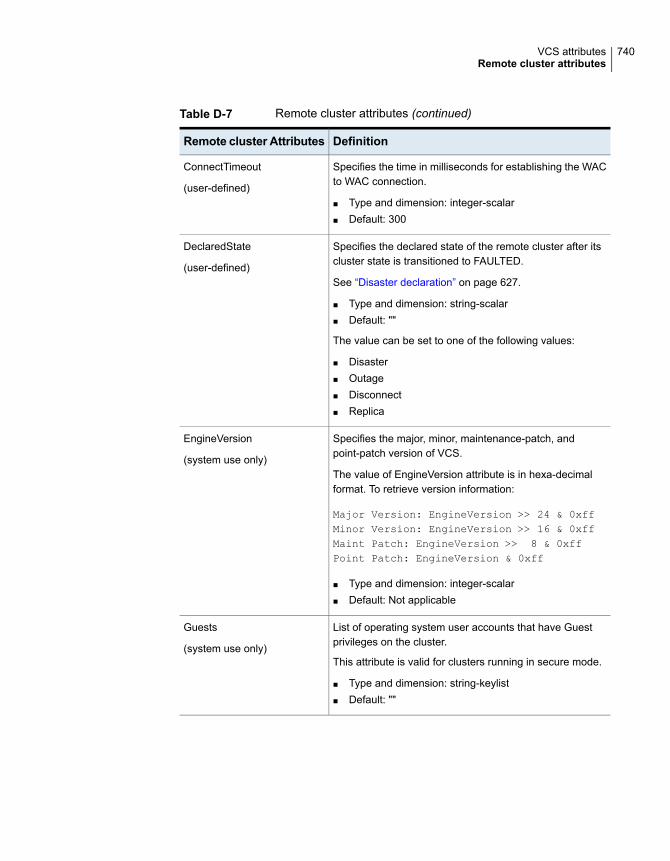
Table D-7 Remote cluster attributes (continued)
DefinitionRemote cluster Attributes
Specifies the time in milliseconds for establishing the WACto WAC connection.
■ Type and dimension: integer-scalar■ Default: 300
ConnectTimeout
(user-defined)
Specifies the declared state of the remote cluster after itscluster state is transitioned to FAULTED.
See “Disaster declaration” on page 627.
■ Type and dimension: string-scalar■ Default: ""
The value can be set to one of the following values:
■ Disaster■ Outage■ Disconnect■ Replica
DeclaredState
(user-defined)
Specifies the major, minor, maintenance-patch, andpoint-patch version of VCS.
The value of EngineVersion attribute is in hexa-decimalformat. To retrieve version information:
Major Version: EngineVersion >> 24 & 0xffMinor Version: EngineVersion >> 16 & 0xffMaint Patch: EngineVersion >> 8 & 0xffPoint Patch: EngineVersion & 0xff
■ Type and dimension: integer-scalar■ Default: Not applicable
EngineVersion
(system use only)
List of operating system user accounts that have Guestprivileges on the cluster.
This attribute is valid for clusters running in secure mode.
■ Type and dimension: string-keylist■ Default: ""
Guests
(system use only)
740VCS attributesRemote cluster attributes
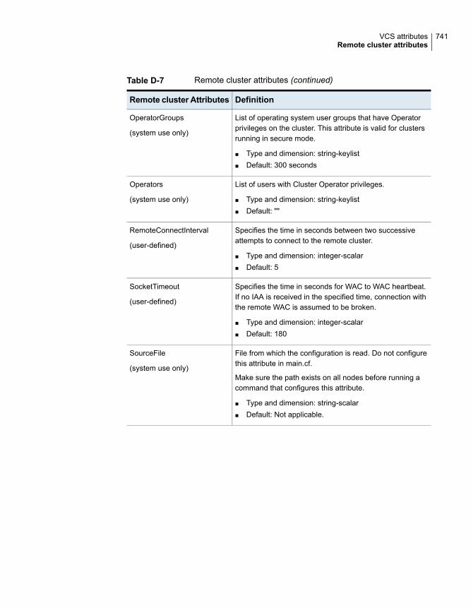
Table D-7 Remote cluster attributes (continued)
DefinitionRemote cluster Attributes
List of operating system user groups that have Operatorprivileges on the cluster. This attribute is valid for clustersrunning in secure mode.
■ Type and dimension: string-keylist■ Default: 300 seconds
OperatorGroups
(system use only)
List of users with Cluster Operator privileges.
■ Type and dimension: string-keylist■ Default: ""
Operators
(system use only)
Specifies the time in seconds between two successiveattempts to connect to the remote cluster.
■ Type and dimension: integer-scalar■ Default: 5
RemoteConnectInterval
(user-defined)
Specifies the time in seconds for WAC to WAC heartbeat.If no IAA is received in the specified time, connection withthe remote WAC is assumed to be broken.
■ Type and dimension: integer-scalar■ Default: 180
SocketTimeout
(user-defined)
File from which the configuration is read. Do not configurethis attribute in main.cf.
Make sure the path exists on all nodes before running acommand that configures this attribute.
■ Type and dimension: string-scalar■ Default: Not applicable.
SourceFile
(system use only)
741VCS attributesRemote cluster attributes

Table D-7 Remote cluster attributes (continued)
DefinitionRemote cluster Attributes
Indicates which VCS features are enabled. Possible valuesare:
0—No features are enabled (VCS Simulator)
1—L3+ is enabled
2—Global Cluster Option is enabled
Even though the VCSFeatures is an integer attribute, whenyou query the value with the haclus -value command or thehaclus -display command, it displays as the string L10N forvalue 1 and DR for value 2.
■ Type and dimension: integer-scalar■ Default: Not applicable.
VCSFeatures
(system use only)
Denotes the mode for which VCS is licensed.
Even though the VCSMode is an integer attribute, whenyou query the value with the haclus -value command or thehaclus -display command, it displays as the stringUNKNOWN_MODE for value 0 and VCS for value 7.
■ Type and dimension: integer-scalar■ Default:Not applicable
VCSMode
(system use only)
The TCP port on which the wac (Wide-Area Connector)process on the remote cluster listens for connection fromother clusters.
■ Type and dimension: integer-scalar■ Default: 14155
WACPort
(system use only)
Site attributesTable D-8 lists the site attributes.
742VCS attributesSite attributes

Table D-8 Site attributes
DefinitionSiteAttributes
Indicates the preference for a site.
■ Type and dimension : integer-scalar■ Default : 3
If preferred fencing is enabled, I/O fencing uses the Preference value tocompute node weight as follows:
Preference Node weight
1 10000
2 1000
3 100
4 10
Preference
(user-defined)
Indicates the list of systems configured under a site.
■ Type and dimension : string-keylist■ Default : ""
SystemList
(user-defined)
743VCS attributesSite attributes

Accessibility and VCSThis appendix includes the following topics:
■ About accessibility in VCS
■ Navigation and keyboard shortcuts
■ Support for accessibility settings
■ Support for assistive technologies
About accessibility in VCSVeritas InfoScale products meet federal accessibility requirements for software asdefined in Section 508 of the Rehabilitation Act:
http://www.access-board.gov/508.htm
Cluster Server provides shortcuts for major graphical user interface (GUI) operationsand menu items. Cluster Server is compatible with operating system accessibilitysettings as well as a variety of assistive technologies. All manuals also are providedas accessible PDF files, and the online help is provided as HTML, which appearsin a compliant viewer.
Navigation and keyboard shortcutsVCS uses standard operating system navigation keys and keyboard shortcuts. Forits unique functions, VCS uses its own navigation keys and keyboard shortcutswhich are documented below.
EAppendix

Navigation in the Web consoleThe Web console supports standard browser-based navigation and shortcut keysfor supported browsers.
All Veritas GUIs use the following keyboard navigation standards:
■ Tab moves the cursor to the next active area, field, or control, following a presetsequence.
■ Shift+Tab moves the cursor in the reverse direction through the sequence.
■ Up-arrow and Down-arrow keys move the cursor up and down the items of alist.
■ Either Enter or the Spacebar activates your selection. For example, after pressingTab to select Next in a wizard panel, press the Spacebar to display the nextscreen.
Support for accessibility settingsVeritas software responds to operating system accessibility settings.
On UNIX systems, you can change the accessibility settings by using desktoppreferences or desktop controls.
Support for assistive technologiesVeritas provides support for assistive technologies as follows:
■ Cluster Manager (Java Console) is compatible with JAWS 4.5.
■ Though graphics in the documentation can be read by screen readers, settingyour screen reader to ignore graphics may improve performance.
■ Veritas has not tested screen readers for languages other than English.
745Accessibility and VCSSupport for accessibility settings
Symbolsremove cluster 518
Aabout
Veritas InfoScale Operations Manager 46accessibility
assistive technology support 745overview 744
ActionTimeout attribute 680ActiveCount attribute 707AdaptiveHA
about 330enabling 330Limitations 333
administeringLLT 94
AdministratorGroups attributefor clusters 737for service groups 707
Administrators attributefor clusters 737for service groups 707
AdvDbg attribute 680agent log
format 582location 582
AgentClass attribute 680AgentDirectory attribute 680AgentFailedOn attribute 680AgentFile attribute 680AgentPriority attribute 680AgentReplyTimeout attribute 680agents
classifications of 40entry points 36framework 41functions 36Heartbeat 466IMF 41impact on performance 545
agents (continued)intelligent monitoring framework 41intelligent resource monitoring 37poll-based resource monitoring 37starting from command line 134stopping from command line 134Wide-Area Heartbeat 466
AgentStartTimeout attribute 680AgentState attribute 738AgentStopped attribute 722AlertOnMonitorTimeouts attribute 680AMF driver 44App.DisplayName 459App.RestartAttempts 459App.StartStopTimeout 459ArgList attribute 680ArgListValues attribute 664assistive technology support 745association attribute dimension 67asymmetric configuration 49AttrChangedTimeout attribute 680attribute dimensions
association 67keylist 67scalar 67vector 67
attribute typesboolean 66integer 66string 66
attributesabout 66for clusters 722for heartbeats 737for resource types 664, 680for resources 655for service groups 680for systems 707local and global 69overriding from command line 151Remote cluster 739
authentication broker 44
Index

Authority attributeabout 466definition 707
AuthorizationControl attribute 737AutoAddSystemtoCSG attribute 737AutoclearLimit attribute
for service groups 707AutoClearQ attribute 737AutoDisabled attribute 707AutoFailOver attribute
about 328definition 707
AutoRestart attribute 707AutoStart attribute
for resources 664for service groups 707
AutoStartIfPartial attribute 707AutoStartList attribute 707AutoStartPolicy attribute 707AutoStartTimeout attribute 737AvailableCapacity attribute 722
BBackupInterval attribute 737BiggestAvailable 330binary message catalogs
about 591location of 591
boolean attribute type 66bundled agents 40
CCapacity attribute 722CapacityReserved attribute 707CleanRetryLimit attribute 680CleanTimeout attribute 680client process
detecting failure 551CloseTimeout attribute 680ClusState attribute 737Cluster Administrator
about 80adding user as 111
cluster attributes 722Cluster Guest
about 80adding user as 111
cluster namechanging in global configuration 517
Cluster Operatorabout 80adding user as 111
ClusterAddress attribute 737ClusterFailOverPolicy attribute 707clustering
criteria for data storage 27criteria for monitor procedure 26criteria for start procedure 26criteria for stop procedure 26license and host name issues 28
ClusterList attribute 707ClusterLocation attribute 737ClusterName attribute 737ClusterOwner attribute 737ClusterRecipients attribute 737ClusterTime attribute 737ClusterUUID attribute 737commands
scripting 163CompareRSM attribute 737ComputeStats attribute 664Concurrency
preventing violation 339conditional statements 122ConfidenceLevel attribute 664ConfigBlockCount attribute 722ConfigCheckSum attribute 722ConfigDiskState attribute 722ConfigFile attribute 722ConfigInfoCnt attribute 722ConfigModDate attribute 722configuration
dumping 109saving 109setting to read-only 109setting to read/write 110taking snapshots of 110verifying 108
configuration filesgenerating 60main.cf 60read/write to read-only 113, 115, 117–118, 120–
121, 128, 130restoring from snaphots 110taking snapshots of 110types.cf 60
747Index

configuration languagelocal and global attributes 69
configurationsasymmetric 49global cluster 57N+1 52N-to-1 51N-to-N 53replicated data 56shared nothing 56shared storage/replicated data 56symmetric 50
ConfInterval attributeabout 346definition 680
ConnectorState attribute 737ContainerInfo attribute 707ContainerOpts attribute 680coordinator disks 227
DMP devices 224for I/O fencing 224
CounterInterval attribute 737CounterMissAction attribute 737CounterMissTolerance attribute 737CP server
cloning 295deployment scenarios 308migration scenarios 308
CP server database 236CP server user privileges 241CPU binding of HAD 556CPUBinding attribute 722Critical attribute 664CurrentCount attribute 707CurrentLimits attribute 722custom agents
about 40
DDaemon Down Node Alive 256DDNA 256DefaultGuestAccess attribute 737DeferAutoStart attribute 707DeleteOnlineResource attribute 737dependencies
for resources 32for service groups 381
DisableFaultMessages attribute 707DiskHbStatus attribute 722
dumping a configuration 109DumpingMembership attribute 737dumptunables event trigger 423dynamic application placement
FailOverPolicy attribute 330DynamicLoad attribute 722
EEnabled attribute
for resources 664for service groups 707
EnableFFDC attribute 737EnablePBF attribute 737EnableVMAutoDiscovery attribute 737engine log
format 582location 582
EngineClass attribute 737EnginePriority attribute 737enterprise agents
about 40entry points
about 36modifying for performance 545
environment variables 70EPClass attribute 680EPPriority attribute 680error messages
agent log 582at startup 600engine log 582message catalogs 591
EvacList attribute 707Evacuate attribute 707Evacuating attribute 707EvacuatingForGroup attribute 707event triggers
about 421dumptunables 423globalcounter_not_updated 423injeopardy 424loadwarning 424location of 422multinicb 425nofailover 426postoffline 426postonline 427preonline 427resadminwait 428
748Index

event triggers (continued)resnotoff 430resrestart 430resstatechange 431sysjoin 433sysoffline 432sysup 433unable_to_restart_had 433–434using 422violation 434
ExternalStateChange attribute 680
Ffailback
about 51Failover attribute 707FailOverPolicy attribute 707FaultOnMonitorTimeouts attribute 680FaultPropagation attribute 680FencingWeight 722FipsMode attribute 737fire drills
about 490disaster recovery 490for global clusters 490for replicated data clusters 526
FireDrill attribute 680Flags attribute 664FromQ attribute 707Frozen attribute
for service groups 707for systems 722
GGAB
about 43, 216impact on performance 544tunable parameters 568when a system panics 551
GAB tunable parametersdynamic 571
Control port seed 571Driver state 571Gab queue limit 571Halt on process death 571Halt on rejoin 571IOFENCE timeout 571Isolate timeout 571
GAB tunable parameters (continued)dynamic (continued)
Keep on killing 571Kill_ntries 571Missed heartbeat halt 571Partition arbitration 571Quorum flag 571Stable timeout 571
static 569gab_conn_wait 569gab_flowctrl 569gab_isolate_time 569gab_kill_ntries 569gab_logbufsize 569gab_msglogsize 569gab_numnids 569gab_numports 569gab_timer_pri 569
gab_isolate_time timer 551global attributes 69global cluster configuration 57global clusters
operation 462global heartbeats
administering from command line 518global service groups
administering from command line 513querying from command line 506
GlobalCounter attribute 737globalcounter_not_updated event trigger 423Group Administrator
about 80adding user as 112
Group attribute 664group dependencies.. See service group
dependenciesGroup Membership Services/Atomic Broadcast
(GAB) 43Group Operator
about 80adding user as 112
GroupLimit attribute 737GroupOwner attribute 707GroupRecipients attribute 707GuestGroups attribute 737Guests attribute
for clusters 737for service groups 707
GUIIPAddr attribute 722
749Index

HHA fire drill
about 211haagent -display command 118haagent -list command 123haattr -add command 137haattr -default command 138haattr -delete command 137hacf -verify command 108hacf utility
creating multiple .cf files 108HacliUserLevel attribute
about 80definition 737
haclus -add command 515haclus -declare command 515haclus -delete command 515haclus -display command
for global clusters 510for local clusters 120
haclus -list command 510haclus -modify command 515haclus -state command 510haclus -status command 511haclus -value command
for global clusters 510for local clusters 120
haclus -wait command 163haconf -dump -makero command 109haconf -makerw command 110HAD
about 41binding to CPU 556impact on performance 544
had -v command 157had -version command 157HAD diagnostics 593hagrp -add command 124hagrp -clear command 131–132hagrp -delete command 124hagrp -dep command 115hagrp -disable command 130hagrp -disableresources command 130hagrp -display command
for global clusters 507for local clusters 115
hagrp -enable command 129hagrp -enableresources command 130
hagrp -forecast commandforecasting target system 116
hagrp -freeze command 129hagrp -link commandd 134hagrp -list command
for global clusters 507for local clusters 123
hagrp -modify command 125hagrp -offline command
for global clusters 513for local clusters 127
hagrp -online commandfor global clusters 513for local clusters 126
hagrp -resources command 115hagrp -state command
for global clusters 507for local clusters 115
hagrp -switch commandfor global clusters 513for local clusters 128
hagrp -unfreeze command 129hagrp -unlink command 134hagrp -value command 506hagrp -wait command 163hahb -add command 518hahb -delete command 518hahb -display command 512hahb -global command 518hahb -list command 511hahb -local command 518hahb -modify command 518hahb command 518halogin command 107hamsg -info command 121hamsg -list command 121hanotify utility 409hares -action command 515hares -add command 135hares -clear command 150hares -delete command 136hares -dep command 116hares -display command
for global clusters 508for local clusters 116
hares -global command 140hares -info command 515hares -link command 148
750Index

hares -list commandfor global clusters 508for local clusters 123
hares -local command 138hares -modify command 136hares -offline command 149hares -offprop command 149hares -online command 149hares -override command 151hares -probe command 150hares -state command 508hares -undo_override command 151hares -unlink command 148hares -value command 508hares -wait command 163hashadow process 41hastart command 102hastatus -group command 120–121hastatus -summary command 121hastatus command
for global clusters 511for local clusters 120
hastop command 104hasys -display command
for global clusters 509for local clusters 119
hasys -force command 102hasys -freeze command 154hasys -list command
for global clusters 509for local clusters 119
hasys -modify command 153hasys -nodeid command 153hasys -state command 509hasys -unfreeze command 154, 157hasys -utilization command
for local clusters 119hasys -value command
for global clusters 509hasys -wait command 163hatype -add command 150hatype -delete command 150hatype -display command 118hatype -list command 117hatype -modify command 150hatype -resources command 118hauser -add command 112hauser -addpriv command 112–113hauser -delete command 114
hauser -delpriv command 113–114hauser -display command 114hauser -list command 114Heartbeat agent 466heartbeat attributes 737heartbeats
modifying for global clusters 518host name issues 28HostAvailableForecast attribute 722HostAvailableMeters attribute 737HostMeters attribute 737HostMonitor attribute 722HostUtilization attribute 722
II/O fencing
about 44testing and scenarios 251
include clausesabout 60
InfoInterval attribute 680InfoTimeout attribute 680injeopardy event trigger 424integer attribute type 66intelligent resource monitoring
disabling manually 140disabling using script 142enabling manually 140enabling using script 142
IntentionalOnlineList attribute 707IntentOnline attribute 707Istate attribute 664
JJava Console
impact on performance 546
Kkeyless license
changing product level 93product level 93setting product level 93
keylist attribute dimension 67keywords 70
list of 70
LLastOnline attribute 664
751Index

LastSuccess attribute 707license keys
about 93installing 93troubleshooting 630
LicenseType attribute 722licensing issues 28Limits attribute 722LinkHbStatus attribute 722LLT 43
about 217tunable parameters 561
LLT timer tunable parameterssetting 568
LLTNodeId attribute 722Load attribute 707Load policy for SGWM 330LoadTimeCounter attribute 722LoadTimeThreshold attribute 722loadwarning event trigger 424LoadWarningLevel attribute 722local attributes 69LockMemory attribute 737log files 622LogClusterUUID attribute 737LogDbg attribute 680LogFileSize attribute 680logging
agent log 582engine log 582message tags 582
LogSize attribute 737Low Latency Transport (LLT) 43
Mmain.cf
about 60cluster definition 60group dependency clause 60include clauses 60resource definition 60resource dependency clause 60service group definition 60system definition 60
ManageFaults attribute 664about 335definition 707
ManualOps attribute 707MemThresholdLevel attribute 722
message tagsabout 582
MeterRecord attribute 722MeterWeight attribute 707MigrateQ attribute 707migrating
service groups 128MonitorInterval attribute 680MonitorMethod attribute 664MonitorOnly attribute 664MonitorStartParam attribute 680MonitorTimeout attribute 680MonitorTimeStats attribute 664multinicb event trigger 425
NN+1 configuration 52N-to-1 configuration 51N-to-N configuration 53Name attribute 664network links
detecting failure 551networks
detecting failure 553NoAutoDisable attribute 722NodeId attribute 722nofailover event trigger 426notification
about 405deleting messages 407error messages 407error severity levels 407event triggers 421hanotify utility 409message queue 407notifier process 408SNMP files 415troubleshooting 626
Notifier attribute 737notifier process 408NumRetries attribute 707NumThreads attribute
definition 680modifying for performance 545
OOfflineMonitorInterval attribute 680OfflineTimeout attribute 680
752Index

OfflineWaitLimit attribute 680On-Off resource 32On-Only resource 32OnGrpCnt attribute 722OnlineAtUnfreeze attribute 707OnlineClass attribute 680OnlinePriority attribute 680OnlineRetryInterval attribute 707OnlineRetryLimit attribute
for resource types 680for service groups 707
OnlineTimeout attribute 680OnlineWaitLimit attribute 680Open IMF
overview 39OpenExternalCommunicationPort attribute 737OpenTimeout attribute 680Operations attribute 680OperatorGroups attribute
for clusters 737for service groups 707
Operators attributefor clusters 737for service groups 707
overload warning for SGWM 362
PPanicOnNoMem attribute 737Parallel attribute 707Path attribute 664PathCount attribute 707PCVAllowOnline attribute 707performance
agents 545GAB 544HAD 544impact of VCS 543Java Console 546modifying entry points 545modifying NumThreads attribute 545when a cluster is booted 547when a network link fails 551when a resource comes online 548when a resource fails 549when a resource goes offline 548when a service group comes online 548when a service group fails over 554when a service group goes offline 549when a service group switches over 553
performance (continued)when a system fails 550when a system panics 551
Persistent resource 32PhysicalServer attribute 722PolicyIntention attribute 707postoffline event trigger 426postonline event trigger 427Preference attribute 743PreferredFencingPolicy attribute 737PreOnline attribute 707preonline event trigger 427PreOnlineTimeout attribute 707PreOnlining attribute 707Prerequisites attribute 707PreSwitch attribute 707PreSwitching attribute 707Prevention of Concurrency Violation
about 339PrintMsg attribute 737PrintTree attribute 707priorities
defaults 555ranges 555scheduling 554specifying 555
Priority attribute 707Priority based failover 130priority ranges for sched. classes 554privileges.. See user privilegesProbed attribute
for resources 664for service groups 707
ProbesPending attribute 707ProcessPriority attribute 737ProPCV attribute 707
Qquick reopen 553
RReadOnly attribute 737Recovering After a Disaster 525Remote cluster attributes 739Remote Cluster States 649Remove remote cluster 518replicated data clusters
about 56
753Index

replicated data configuration 56resadminwait event trigger 428reserved words 70
list of 70ReservedCapacity attribute 722resnotoff event trigger 430resource attributes 655resource dependencies
creating from command line 148displaying from command line 116removing from command line 148
resource type attributes 664, 680resource types
querying from command line 117ResourceInfo attribute
definition 664ResourceLimit attribute 737ResourceOwner attribute 664ResourceRecipients attribute 664resources
about 30adding from command line 135bringing online from command line 149categories of 32deleting from command line 136disabling from command line 354enabling from command line 130how disabling affects states 357limitations of disabling 355linking from command line 148On-Off 32On-Only 32Persistent 32querying from command line 116taking offline from command line 149troubleshooting 610unlinking from command line 148
Responding attribute 707resrestart event trigger 430resstatechange event trigger 431Restart attribute 707RestartLimit attribute
about 346definition 680
root broker 44
Ssaving a configuration 109scalar attribute dimension 67
scheduling classes 554defaults 555priority ranges 555
ScriptClass attribute 680scripting VCS commands 163ScriptPriority attribute 680SCSI-3 Persistent Reservations 243SecInfo attribute 737SecInfoLevel attribute 737secure communication 242secure mode for clusters
disabling 161enabling 161
secure VCS.. See Veritas Product AuthenticationService
SecureClus attribute 737security 241server-based fencing
replacing coordination pointsonline cluster 304
ServerAvailableCapacity 722ServerAvailableForecast 722ServerCapacity 722ServerReservedCapacity 722service group attributes 680service group dependencies
about 381autorestart 327benefits of 381creating 401limitations of 385manual switch 403
service group workload managementCapacity and Load attributes 361load policy 330load-based autostart 335overload warning 362sample configurations 364SystemZones attribute 334
service groupsadding from command line 124administering from command line 123bringing online from command line 126deleting from command line 124displaying dependencies from command line 115flushing from command line 132freezing from command line 129migrating 128querying from command line 114–115
754Index

service groups (continued)switching from command line 128troubleshooting 604unfreezing from command line 129
Settings 459shared nothing configuration 56shared storage/replicated data configuration 56ShutdownTimeout attribute 722Signaled attribute 664SiteAware attribute 737sites
troubleshooting 612SNMP 405
files for notification 415HP OpenView 415merging events with HP OpenView NNM 415supported consoles 405
SourceFile attributefor clusters 737for resource types 680for service groups 707for systems 722
split-brainin global clusters 470
Start attribute 664State attribute
for resources 664for service groups 707
Statistics attribute 737steward process
about 470Stewards attribute 737string attribute type 66SupportedActions attribute 680SupportedOperations attribute 680symmetric configuration 50SysDownPolicy attribute 707SysInfo attribute 722sysjoin event trigger 433SysName attribute 722sysoffline event trigger 432SysState attribute 722system attributes 707system states 651SystemList attribute 743
about 63, 125definition 707modifying 125
SystemLocation attribute 722
SystemOwner attribute 722SystemRebootAction attribute 737SystemRecipients attribute 722systems
adding from command line 157administering from command line 153client process failure 551detecting failure 550displaying node ID from command line 154panic 551quick reopen 553removing from command line 157states 651
systems and nodes 28SystemZones attribute 707sysup event trigger 433
TTag attribute 707target selection 330TargetCount attribute 707TFrozen attribute
for service groups 707for systems 722
ToleranceLimit attribute 680ToQ attribute 707TriggerEvent attribute
for resources 664for service groups 707
TriggerPath attributefor resources 664for service groups 707
TriggerResFault attribute 707TriggerResRestart attribute
for resources 664for service groups 707
TriggerResStateChange attributefor resources 664for service groups 707
triggers.. See event triggersTriggersEnabled attribute
for resources 664for service groups 707
troubleshootinglicense keys 630logging 582notification 626resources 610service groups 604
755Index

troubleshooting (continued)sites 612VCS startup 600
TRSE attribute 722TypeDependencies attribute 707TypeLimit attribute 737TypeOwner attribute 680TypeRecipients attribute 680types.cf 60
Uumask
setting for VCS files 74unable_to_restart_had trigger 433–434UnSteadyCount attribute 707UpDownState attribute 722upgrade main.cf 333UseFence attribute 737user privileges
about 79assigning from command line 112–113Cluster Administrator 80Cluster Guest 80Cluster Operator 80for specific commands 637Group Administrator 80Group Operator 80removing from command line 112–114
UserAssoc attribute 707UserInt attribute 722UserIntGlobal attribute 707UserIntLocal attribute 707UserNames attribute 737users
deleting from command line 114displaying from command line 114
UserStrGlobal attribute 707UserStrLocal attribute 707utilities
hanotify 409vxkeyless 93vxlicinst 93
Utilization 664
VVCS
accessibility 744additional considerations for stopping 106
VCS (continued)assistive technology support 745event triggers 421logging 582logging off of 107logging on to 107notification 405querying from command line 114SNMP and SMTP 405starting from command line 102starting with -force 102stopping from command line 104stopping with other options 105stopping without -force 104troubleshooting resources 610troubleshooting service groups 604troubleshooting sites 612
VCS agent statistics 558VCS attributes 66VCS Simulator
description of 165VCSFeatures attribute
for clusters 737for systems 722
VCSMode attribute 737vector attribute dimension 67Veritas Product Authentication Service
about 44authentication broker 44root broker 44
version informationretrieving 157
violation event trigger 434Virtual Business Services
features 435overview 435sample configuration 436
virtual fire drillabout 211
vxfen.. See fencing modulevxkeyless utility 93vxlicinst utility 93
Wwac 465WACPort attribute 737wide-area connector 465wide-area failover 57
VCS agents 467
756Index

Wide-Area Heartbeat agent 466
757Index


