36
CNC Precision Automatic Lathe Series

CNC Precision Automatic Lathe
Series
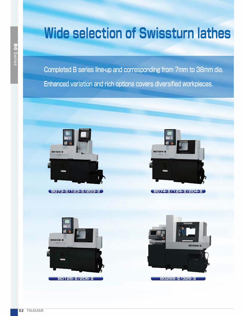
Wide selection of Swissturn lathes
Completed B series line-up and corresponding from 7mm to 38mm dia.
Enhanced variation and rich options covers diversified workpieces.
B073-Ⅱ/123-Ⅱ/203-Ⅱ B074-Ⅱ/124-Ⅱ/204-Ⅱ
B0126-Ⅱ/206-Ⅱ B0266-Ⅱ/326-Ⅱ
02
B0
Se
ries
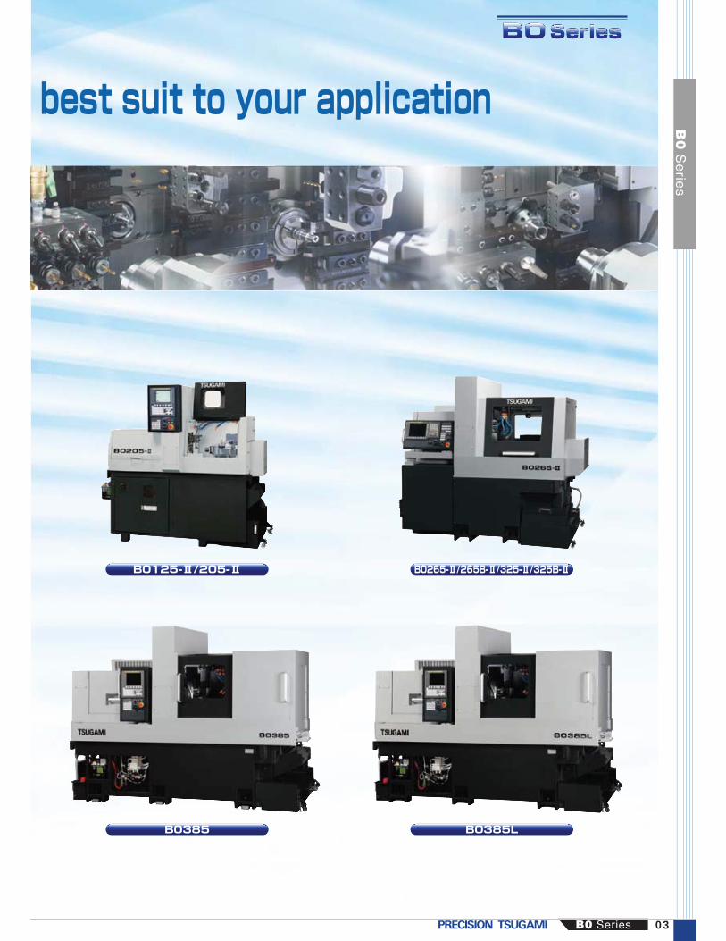
best suit to your application
B0125-Ⅱ/205-Ⅱ B0265-Ⅱ/265B-Ⅱ/325-Ⅱ/325B-Ⅱ
B0385 B0385L
B0 Series 03
B0
Se
ries

Number of toolsOD tool storage capacity
Cross-rotary9OP.4---13
Front & back simultaneous machiningBack spindle
Cross rotary toolGuide-bush-less kit
Direct-drive guide bushingC-axis
Cross rigid tap
--OP.OP.OP.OP.OP.
Front
Back
FixedRotaryFixedRotary
Total tool storage capacity
φ7 mm3-axis control
φ12 mm3-axis control
φ20 mm3-axis control
Basic machines provide maximum profits by the minimal investment.
B073-Ⅱ/123-Ⅱ/203-Ⅱφ7 mm4-axis control
φ12 mm4-axis control
φ20 mm4-axis control
Built-in back spindle
B074-Ⅱ/124-Ⅱ/204-Ⅱφ20 mm 5-axis controlφ12 mm 5-axis control
Front & back simultaneous machining
B0125-Ⅱ/205-Ⅱ
9OP.4-
8, OP. (6)OP. (2)21
Front & back simultaneous machiningBack spindle
Cross rotary toolBack rotary toolGuide-bush-less kit
Direct-drive guide bushingC-axis
Cross rigid tapBack rigid tapping
○○OP.OP.OP.OP.OP.OP.OP.
9OP.4-4-17
-○OP.OP.OP.OP.OP.
1247OP.44
31 (Standard)
○○○○OP.OP.○OP.OP.
843OP.8OP.
23 (Standard)
○○○OP.--○OP.OP.
Number of toolsOD tool storage capacity4-spindle cross-rotary
843OP.8OP.
23 (Standard)
Front & back simultaneous machiningBack spindle
4-spindle cross rotary toolBack rotary toolGuide-bush-less kit
Direct-drive guide bushingC-axis
Cross rigid tapBack rigid tapping
Front & back simultaneous machiningBack spindle
4-spindle cross rotary toolBack rotary toolGuide-bush-less kit
Direct-drive guide bushingC-axis
Cross rigid tapBack rigid tapping
Front & back simultaneous machiningBack spindle
4-spindle cross rotary toolBack rotary toolGuide-bush-less kit
Direct-drive guide bushingC-axis
Cross rigid tapBack rigid tapping
○○○OP.○-○OP.OP.
Front
Back
FixedRotaryFixedRotary
Total tool storage capacity
Number of toolsOD tool storage capacity4-spindle cross-rotary
Front
Back
FixedRotaryFixedRotary
Total tool storage capacity
Number of toolsOD tool storage capacity4-spindle cross-rotary
Front
Back
FixedRotaryFixedRotary
Total tool storage capacity
Note that the combination of C-axis and rotary tool has restrictions.※Tool spindle (Back tool post) is optional. Note that the combination of C-axis and rotary tool has restrictions.
Front and back simultaneous processing including milling thanks to the Y2 axis control
B0266-Ⅱ/B0326-Ⅱφ26 mm 6-axis control φ32 mm 6-axis control
B0385φ38 mm 5-axis control
B0385Lφ38 mm 5-axis control Guide Bushless Configuration
Note that the combination of C-axis and rotary tool has restrictions.
Z1
Z2
X1
Y1
Z1
Y1
X1
Z2
X2
Z1
X2
Z2
X1
Y1
Y2
C1
C2
X1
Y1Options
X2
Z2
Z1
C2
X1
Y1Options
X2
Z2
Z1
C2
Number of toolsOD tool storage capacity
Cross-rotary
Front
Back
FixedRotaryFixedRotary
Total tool storage capacity
Number of toolsOD tool storage capacity
Cross-rotary
Front
Back
FixedRotaryFixedRotary
Total tool storage capacity
Front & back simultaneous machiningBack spindle
Cross rotary toolGuide-bush-less kit
Direct-drive guide bushingC-axis
Cross rigid tap
Front & back simultaneous machining Front & back simultaneous machining
Z1
Y1
X1
04
B0
Se
ries

Front and back simultaneous processing including milling thanks to the Y2 axis control
B0126-Ⅱ/206-Ⅱφ12 mm 6-axis control φ20 mm 6-axis controlφ32 mm 5-axis controlφ26 mm 5-axis control
Front & back simultaneous machining
B0265-Ⅱ/B0325-Ⅱ
○○OP.○OP.OP.○OP.OP.
9OP.4-8
Front2/Cross225
Front & back simultaneous machiningBack spindle
Cross rotary toolBack rotary toolGuide-bush-less kit
Direct-drive guide bushingC-axis
Cross rigid tapBack rigid tapping
Number of toolsOD tool storage capacity
Cross-rotary
Front
Back
FixedRotaryFixedRotary
Total tool storage capacity
1247OP.4OP.
27 (Standard)
Front & back simultaneous machiningBack spindle
4-spindle cross rotary toolBack rotary toolGuide-bush-less kit
Direct-drive guide bushingC-axis
Cross rigid tapBack rigid tapping
○○○OP.OP.OP.OP.OP.OP.
Note that the combination of C-axis and rotary tool has restrictions.
Z1
X2
Z2
X1
Y1
Number of toolsOD tool storage capacity4-spindle cross-rotary
Front
Back
FixedRotaryFixedRotary
Total tool storage capacity
φ32 mm 5-axis controlφ26 mm 5-axis control
Front & back simultaneous machining
B0265B-Ⅱ/B0325B-Ⅱ
1247OP.4OP.
27 (Standard)
Front & back simultaneous machiningBack spindle
4-spindle cross rotary toolBack rotary toolGuide-bush-less kit
Direct-drive guide bushingC-axis
Cross rigid tapBack rigid tapping
○○○OP.OP.OP.○OP.OP.
Z1
X2
Z2
X1
Y1
Number of toolsOD tool storage capacity4-spindle cross-rotary
Front
Back
FixedRotaryFixedRotary
Total tool storage capacity
C1
C2X2
Z2
Y2Y1
X1
Z1C1
C2
Controllable linear axis and functions
Back spindleBack tool postBack tool post with Y2 axis
3-axis 4-axis 5-axis 6-axisーーー
○ーー
○ー○
○○ー
3-axis control:
4-axis control:
5-axis control:
6-axis control:
Dedicated front side machining only,
without back spindle
With back spindle, the parted-off side
machining is possible. Tool post is
mutual use.
By the dedicated tool post for back
machining, front & back simultaneous
machining is possible and more
productive than 4-axis machine.
Thanks to the Y2 axis on back tool
post, milling capability is improved on
the back side machining.
Y2
Back spindle
Back tool postBack tool post with Y2 axis
B0 Series 05
B0
Se
ries
06
B0
Se
ries
0 100 200 300 350
φ38 x 250 mm
φ20 x 210 mm
φ20 x 210 mm
φ20 x 210 mm
φ12 x 210 mm
φ12 x 210 mm
φ12 x 210 mm
φ7 x 70 mm
φ7 x 70 mm
φ32 x 320 mm
φ32 x 320 mm
φ32 x 320 mm
Z axison B.S.
Page X-,Z-axison B.S.
Back toolpost
Back toolpost withlive tool
Back toolpost withY2 axis
Direct-drive
Carrier type32i-B0i-TD
Guide-bush-less
Guide-bushNC unit (FANUC)
Double Spindle (GB exclusive)
Max. dia. x Max. length (mm)
φ12 x 210 mm
φ20 x 210 mm
φ38 x 100 mm
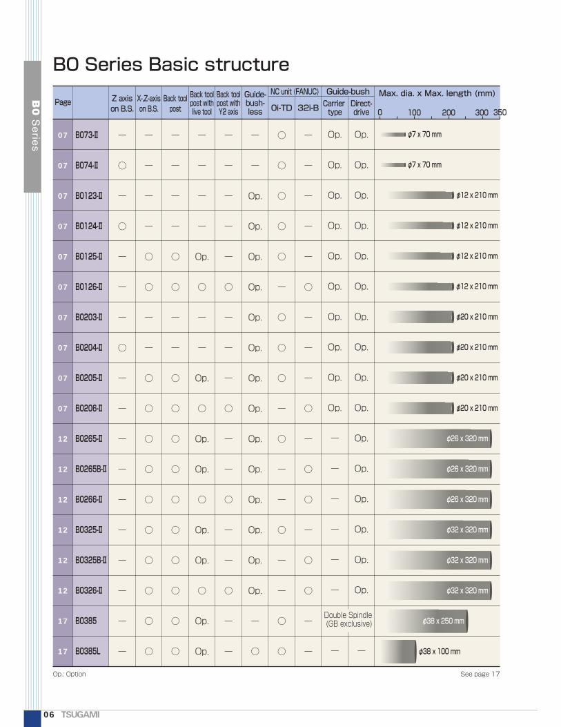
B0 Series Basic structure
φ26 x 320 mm
φ26 x 320 mm
φ26 x 320 mm
B073-Ⅱ
B074-Ⅱ
B0123-Ⅱ
B0124-Ⅱ
B0125-Ⅱ
B0126-Ⅱ
B0203-Ⅱ
B0204-Ⅱ
B0205-Ⅱ
B0206-Ⅱ
B0265-Ⅱ
B0265B-Ⅱ
B0266-Ⅱ
B0325-Ⅱ
B0325B-Ⅱ
B0326-Ⅱ
B0385
B0385L
ー
○
ー
○
ー
ー
ー
○
ー
ー
ー
ー
ー
ー
ー
ー
ー
ー
07
07
07
07
07
07
07
07
07
07
12
12
12
12
12
12
17
17
ー
ー
ー
ー
○
○
ー
ー
○
○
○
○
○
○
○
○
○
○
ー
ー
ー
ー
○
○
ー
ー
○
○
○
○
○
○
○
○
○
○
ー
ー
ー
ー
ー
○
ー
ー
ー
○
ー
ー
○
ー
ー
○
ー
ー
ー
ー
Op.
Op.
Op.
Op.
Op.
Op.
Op.
Op.
Op.
Op.
Op.
Op.
Op.
Op.
ー
○
○
○
○
○
○
ー
○
○
○
ー
○
ー
ー
○
ー
ー
○
○
ー
ー
ー
ー
ー
○
ー
ー
ー
○
ー
○
○
ー
○
○
ー
ー
ー
ー
ー
ー
Op.
○
ー
ー
Op.
○
Op.
Op.
○
Op.
Op.
○
Op.
Op.
Op.
Op.
Op.
Op.
Op.
Op.
Op.
Op.
Op.
Op.
ー
ー
ー
ー
ー
ー
ー
Op.
Op.
Op.
Op.
Op.
Op.
Op.
Op.
Op.
Op.
Op.
Op.
Op.
Op.
Op.
Op.
ー
Op.: Option See page 17

Basic machine Built-in back spindle
Back tool post Back tool post with Y-axis
■Complete simultaneous machining is possible with back tool post (B0125-Ⅱ/B0205-Ⅱ/B0126-Ⅱ/B0206-Ⅱ)■Moreover, simultaneous machining including milling is possible by adding Y-axis on the back tool post (B0126-Ⅱ/B0206-Ⅱ)■Optional direct-drive rotary guide bushing provides high speed and accurate machining.■Guide-bush type or guide-bushless type is selectable according to workpieces.■Easy to use thanks to abundant and extensive software (Standard)■Automatic programming system prepared as standard
Cross drilling
End milling, off-center cross drilling or tapping
Y1 axis
X1 axis
Z1axis
Y1 axis
X1 axis
Y1 axis
X1 axis
Z2
X2
Z1 axis
Z1axis
Z1
C1
C2X2
Z2
Y2
Y1X1
Z1
B0 Series 07
B0
Se
ries
B0125-ⅡB0205-ⅡB0126-ⅡB0206-Ⅱ
B073-ⅡB0123-ⅡB0203-ⅡB074-ⅡB0124-ⅡB0204-Ⅱ
φ7 φ12 φ20
3-axis control
φ7 φ12 φ20
4-axis control
φ12 φ20
5-axis control
φ12 φ20
6-axis control
Y-axis milling with cross tool spindle

B0125-Ⅱ/205-Ⅱ
2 spindles on the far side of back tool post2 spindles on the far side of back tool post
Fixed tool (2)Fixed tool (2)
Achieving milling operation on back side with optional live tools
Back live tools
■■■Type 2: One front drill + One cross drill
■■Type 1: Two front drill units
Both-sided millingSlotting
Swivel
Cross drilling/tappinng
End milling Slotting Endmilling (Endface)
Off-center drilling/tapping
Contouring (Torx head)
■Machining Patterns of back milling
■SpecificationItem
SpecificationMax. speed Max. drilling dia. Max. tapping dia. Motor output Applicable collet8,000 min-1
Live tools
Fixed tool 2 tools
Type 1
Front: 2 spindles (non-modular type)
1 tool
Type 2Cross: 1 spindle (modular type) (horizontal/vertical: cross/slotting)Front: 1 spindle (Non-modular type)
φ6 M5 0.75 kW AR11
■B0125-Ⅱ/205-Ⅱ Restriction of combination (Take note at ordering)Rotary guide bushingDirect driven
Live tools Spindle indexingCarrier driven Cross Back Main spindle Back spindle
―○○○○
①②③④*⑤*
○――――
○○
○○
○
○○○
C axisC axisC axisC axis1°, 15°
C axisC axisC axis1°, 15°C axis
*By the optional C-axis switching function, adapting C-axis whether on the main spindle or the back spindle, such as the combinations of ④&⑤, can be selected by the soft key. After switching, be sure to shut down the NC switch once.
Specification and restriction B0126-Ⅱ and B0206-Ⅱ do not have this restriction since the NC is 32i-B
On B0125-Ⅱ/205-Ⅱ, back side off-center drilling, off-center tapping or endmilling can be overlapped with the main side machining.
Max. speedMax. drilling dia.Max. tapping dia.Motor outputApplicable collet
5,000 min-1
φ6M5 x 0.80.75 kWAR11
B0125-ⅡB0205-ⅡB0125-ⅡB0205-Ⅱ
Cross drilling/ tapping
Speed command by S code /Rigid tap is invalid
Speed command by S code /Rigid tap is invalid
B0125-Ⅱ/B0205-Ⅱ
08
B0
Se
ries

B0126-Ⅱ/206-Ⅱ
By adding Y-axis on the back tool post, the milling capability on the back side is improved even on the small size machines.
Thread whirling
Y2
Fixed tool (4)
Live tools (4)・Cross:2・End face:2
■Specification
Back end milling Back cross drilling/tapping
Back slotting Endmilling (Endface)
Off-center drilling/Tapping
Contouring (with back spindle C axis control)
■Machining Patterns of back milling
■Spec. for whirling unitMax. machining dia. Cutting depth Inclined angle Max. cutter speed Number of OD tools
φ9 MAX. 2.5 mm 0° to 30° 4,000 min-1 6
■Spec. for one spindle cross drillMax. drilling dia. Max. tapping dia. Max. speed Applicable collet
φ6 M5 x 0.8 5,000 min-1 AR11
Y1
X1Z2X2
Z1
Y2
C2
C1
On B0126-Ⅱ and B0206-Ⅱ simultaneous machining including milling such as off-center drilling, off-center tapping, endmilling, or cross drilling on back side is possible by adding Y-axis on the back tool post
End face Cross
AR11 x 2Live tool
Max. speed: 8,000 min-1
Non-modular type
φ20 x 4 holesFixed tool
AR11 x 2
Back tool post ItemSpecification
Max. speed Max. drilling dia. Max. tapping dia. Motor output Applicable collet8,000 min-1 φ6 M5 0.75 kW AR11
Cross off-center drilling/tapping
B0126-ⅡB0206-ⅡB0126-ⅡB0206-Ⅱ
B0126-Ⅱ/B0206-Ⅱ
09
B0125-ⅡB0205-ⅡB0126-ⅡB0206-Ⅱ
B0
Se
ries
B0 Series

Direct-drive rotary guide bushing assures increase of spindle speed.
Specialized machine for miniaturizing microprecision IT-related partsChucking bar stock dia(φ1 to φ7 mm)
Guide-bush type or guide-bushless type is selectable according to workpieces.
■Solid performance
Improved geometrical accuracy, dimensional accuracy, and surface roughness with high speed and quiet operation.The water-soluble coolant is not available.
■Possible to switch between the guide bushing type and guide-bushing-less type so that most suitable operation depend on the workpiece length can be chosen.■The spindle without a guide bushing does not require ground bar, enabling high speed and high precision machining from cold drawn bars. The shortest possible remnant length is 30 mm.
Toggles are replaced with Tsugami's outstanding chuck operation mechanism, which has excellent response and balance characteristics. This contributes to improve roundness in high-speed machining. Ceramic ball bearings contributes to the improvement in the stable surface finish / surface roughness, and tool life in high-speed machining.
■Improved operabilityClearance of the guide bushing can be adjusted from tooling zone side.The optimum work catcher for micro workpieces that can be dischargedboth from the back spindle side or cutting-off side is equipped as standard.
B073-Ⅱ/B074-Ⅱ
Guide bushing type
(Carrier type rotary guide bushing)Remnant length
Guide-bushless type
Remnant length
Direct-drive rotary guide bush unit
12,000 min-1
12,000 min-1
10,000 min-1
70 mm170 mm170 mm
B073/B074-ⅡB0123/124/125-ⅡB0203/204/205-Ⅱ
Max. speed Machining length
180 mm 210 mm 30 mmB0123/124/125-ⅡB0203/204/205-Ⅱ
Carrier type rotaryguide bushingRemnant length Guide-bushlessDirect-drive
guide bushing
■■■Stationary guide bushing■■■Carrier type rotary guide bushing■■Guide-bushing-less kit■■■Direct-drive rotary guide bush
10
B0
Se
ries
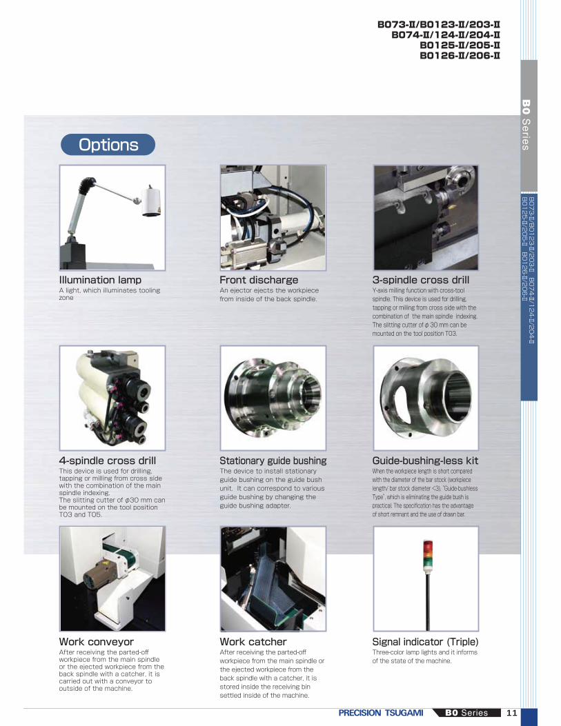
Options
Illumination lampA light, which illuminates tooling zone
Front dischargeAn ejector ejects the workpiece from inside of the back spindle.
3-spindle cross drill
4-spindle cross drillThis device is used for drilling, tapping or milling from cross side with the combination of the main spindle indexing.The slitting cutter of φ30 mm can be mounted on the tool position T03 and T05.
Stationary guide bushingThe device to install stationary guide bushing on the guide bush unit. It can correspond to various guide bushing by changing the guide bushing adapter.
Guide-bushing-less kitWhen the workpiece length is short compared with the diameter of the bar stock (workpiece length/ bar stock diameter <3), “Guide-bushless Type”, which is eliminating the guide bush is practical. The specification has the advantage of short remnant and the use of drawn bar.
Work conveyorAfter receiving the parted-off workpiece from the main spindle or the ejected workpiece from the back spindle with a catcher, it is carried out with a conveyor to outside of the machine.
Work catcherAfter receiving the parted-off workpiece from the main spindle or the ejected workpiece from the back spindle with a catcher, it is stored inside the receiving bin settled inside of the machine.
Signal indicator (Triple)Three-color lamp lights and it informs of the state of the machine.
B073-Ⅱ/B0123-Ⅱ/203-ⅡB074-Ⅱ/124-Ⅱ/204-Ⅱ
B0125-Ⅱ/205-ⅡB0126-Ⅱ/206-Ⅱ
Y-axis milling function with cross-tool spindle. This device is used for drilling, tapping or milling from cross side with the combination of the main spindle indexing.The slitting cutter of φ 30 mm can be mounted on the tool position T03.
B0 Series 11
B0
Se
ries
B073-Ⅱ/B0123-Ⅱ/203-Ⅱ B074-Ⅱ/124-Ⅱ/204-Ⅱ
B0125-Ⅱ/205-Ⅱ B0126-Ⅱ/206-Ⅱ

■Machine complex parts simultaneously on main and back spindles with the Y-axis tool post (B0266-Ⅱ/B0326-Ⅱ).■Modular type live tools (option) for optimum allocation of machining capability.■Beside the back spindle, additional tool post is attached. Deep hole drilling (up to 100 mm) can be realized. In addition, by adopting optional live tool beside the back spindle, the ability of front off-center machining is increased.■Optional direct-drive rotary guide bushing provides high speed and accurate machining.■Guide-bush type or guide-bushless type is selectable according to workpieces.■Pursuing operatability thanks to enriched standard softwares■Automatic programming system prepared as standard
12
B0
Se
ries
B0265-Ⅱ B0266-Ⅱ B0265B-Ⅱ B0325B-Ⅱ B0325-Ⅱ B0326-Ⅱ
φ26
φ32
Z1
X2
Z2
X1
Y1
Y2
C1
C2
φ26
φ32
Z1
X2
Z2
X1
Y1
φ26
φ32
Z1
X2
Z2
X1
Y1
6-axis control
6-axis control
5-axis control
5-axis control
5-axis control
5-axis controlC1(Standard)
C2(Standard)

Modular toolingVarious arrangement of live tools, ID holders and turning holders
Angular drilling head Back cross tool spindle Thread whirling head
B0265-Ⅱ/266-ⅡB0265B-Ⅱ/325B-ⅡB0325-Ⅱ/326-Ⅱ
Z1
X2
Z2
X1
Y1
Y2
Front tool post
Back tool post
Rear tool post
4-spindle cross live tool (standard)●AR16 x 3●AR20 x 1
Frontal drilling head●φ25 x 5Turning tool●□16 x 2
Turning tool●□16 x 5
Rear drive (Op.)
●For fixed toolsφ25 x 4●For live toolsAR16 x 4 (B0266-Ⅱ/B0326-Ⅱ)
Turning tool●□16 x 5
Live tool beside the back spindle (Op.)
Deep hole drill holder (standard)
Op.: OptionType: B0266-Ⅱ/B0326-Ⅱ
Adapter for fixed tool (Op.)
Tool spindle (Op.)
p (Op.)
Multiplied tool spindle (0p.) (Max.20,000min-1)
Back cross tool spindle (Op.)
Tool spindle (Op.)
Hobbing head(Op.)
Angular drilling head (Op.)
Double face spindle (Op.)
Multiplied tool spindle (0p.) (Max.20,000min-1)
Thread whirling head(Op.)
C1
C2
B0 Series 13
B0
Se
ries
B0265-Ⅱ B0266-Ⅱ B0265B-Ⅱ B0325B-Ⅱ B0325-Ⅱ B0326-Ⅱ
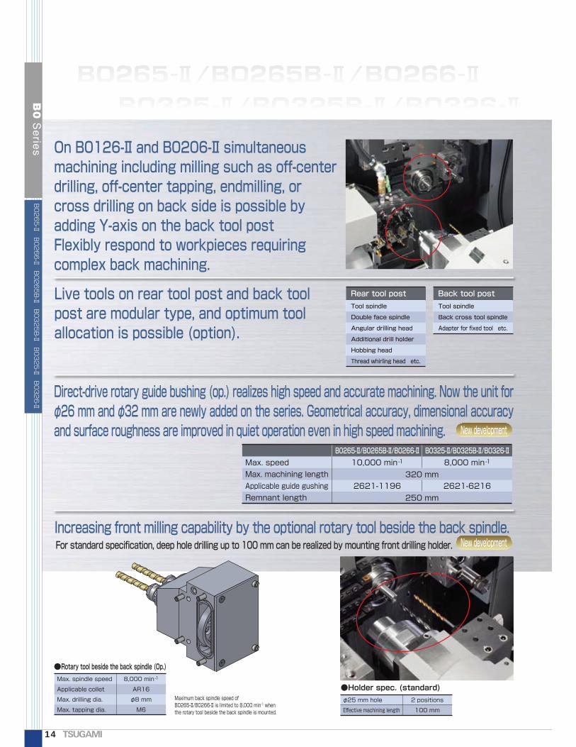
On B0126-Ⅱ and B0206-Ⅱ simultaneous machining including milling such as off-center drilling, off-center tapping, endmilling, or cross drilling on back side is possible by adding Y-axis on the back tool postFlexibly respond to workpieces requiring complex back machining.
Live tools on rear tool post and back tool post are modular type, and optimum tool allocation is possible (option).
Rear tool post Back tool postTool spindle
Back cross tool spindle
Adapter for fixed tool etc.
Direct-drive rotary guide bushing (op.) realizes high speed and accurate machining. Now the unit for φ26 mm and φ32 mm are newly added on the series. Geometrical accuracy, dimensional accuracy and surface roughness are improved in quiet operation even in high speed machining.
Max. speedMax. machining lengthApplicable guide gushingRemnant length
10,000 min-1
2621-1196
8,000 min-1
2621-6216
B0265-Ⅱ/B0265B-Ⅱ/B0266-Ⅱ B0325-Ⅱ/B0325B-Ⅱ/B0326-Ⅱ
New development
New developmentIncreasing front milling capability by the optional rotary tool beside the back spindle. For standard specification, deep hole drilling up to 100 mm can be realized by mounting front drilling holder.
●Rotary tool beside the back spindle (Op.)Max. spindle speed
Applicable collet
Max. drilling dia.
Max. tapping dia.
8,000 min-1
AR16
φ8 mm
M6
Maximum back spindle speed of B0265-Ⅱ/B0266-Ⅱ is limited to 8,000 min-1 when the rotary tool beside the back spindle is mounted.
●Holder spec. (standard)φ25 mm hole
Effective machining length
2 positions
100 mm
320 mm
250 mm
Tool spindle
Double face spindle
Angular drilling head
Additional drill holder
Hobbing head
Thread whirling head etc.
14
B0
Se
ries
B0265-Ⅱ B0266-Ⅱ B0265B-Ⅱ B0325B-Ⅱ B0325-Ⅱ B0326-Ⅱ
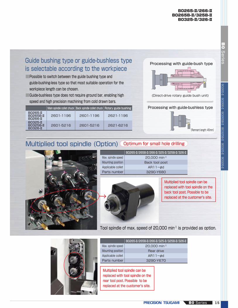
Processing with guide-bush type
(Direct-drive rotary guide bush unit)
Processing with guide-bushless type
(Remnant length: 45mm)
B0265-Ⅱ/266-ⅡB0265B-Ⅱ/325B-ⅡB0325-Ⅱ/326-Ⅱ
Guide bushing type or guide-bushless type is selectable according to the workpiece
Multiplied tool spindle (Option)
2601-1196
2601-5216
2601-1196
2601-5216
2621-1196
2621-6216
Main spindle collet chuck Rotary guide bushingBack spindle collet chuck
■Possible to switch between the guide bushing type and guide-bushing-less type so that most suitable operation for the workpiece length can be chosen.■Guide-bushless type does not require ground bar, enabling high speed and high precision machining from cold drawn bars.
Max. spindle speedMounting positionApplicable colletParts number
B0265-Ⅱ/265B-Ⅱ/266-Ⅱ/325-Ⅱ/325B-Ⅱ/326-Ⅱ20,000 min-1
Back tool postAR11-φd3290-Y680
B0265-Ⅱ/265B-Ⅱ/266-Ⅱ/325-Ⅱ/325B-Ⅱ/326-Ⅱ20,000 min-1
Rear driveAR11-φd3290-Y670
Optimum for small hole drilling
Multiplied tool spindle can be replaced with tool spindle on the back tool post. Possible to be replaced at the customer's site.
Tool spindle of max. speed of 20,000 min-1 is provided as option.
Max. spindle speedMounting positionApplicable colletParts number
B0265-ⅡB0265B-ⅡB0266-ⅡB0325-ⅡB0325B-ⅡB0326-Ⅱ
Multiplied tool spindle can be replaced with tool spindle on the rear tool post. Possible to be replaced at the customer's site.
↑
B0 Series 15
B0
Se
ries
B0265-Ⅱ B0266-Ⅱ B0265B-Ⅱ B0325B-Ⅱ B0325-Ⅱ B0326-Ⅱ
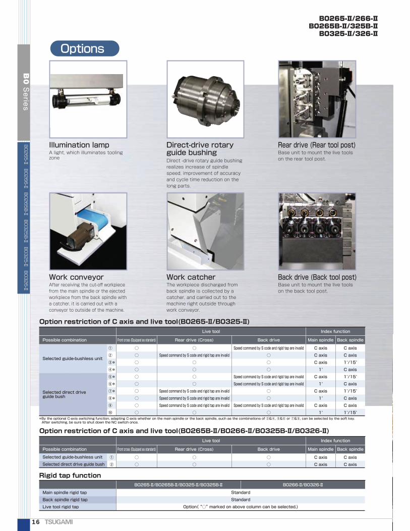
Options
B0265-Ⅱ/266-ⅡB0265B-Ⅱ/325B-ⅡB0325-Ⅱ/326-Ⅱ
Rigid tap functionB0265-Ⅱ/B0265B-Ⅱ/B0325-Ⅱ/B0325B-Ⅱ B0266-Ⅱ/B0326-Ⅱ
Main spindle rigid tap
Back spindle rigid tap
Live tool rigid tap
Standard
Standard
Option( “○” marked on above column can be selected.)
Option restriction of C axis and live tool(B0265B-Ⅱ/B0266-Ⅱ/B0325B-Ⅱ/B0326-Ⅱ)Live tool Index function
Front cross (Equipped as standard) Rear drive (Cross) Back drive Main spindle Back spindle
○
○
C axis
C axis
○
○
C axis
C axis
○
○
①
②
Possible combination
Selected guide-bushless unit
Selected direct drive guide bush
Base unit to mount the live tools on the back tool post.
Option restriction of C axis and live tool(B0265-Ⅱ/B0325-Ⅱ)Live tool Index function
Front cross (Equipped as standard) Rear drive (Cross) Back drive Main spindle Back spindle
Speed command by S code and rigid tap are invalid
○
○
○
Speed command by S code and rigid tap are invalid
Speed command by S code and rigid tap are invalid
○
○
Speed command by S code and rigid tap are invalid
○
C axis
C axis
C axis
1°
C axis
1°
C axis
1°
C axis
1°
○
○
○
○
○
○
○
○
○
○
C axis
C axis
1°/15°
C axis
1°/15°
C axis
1°/15°
C axis
C axis
1°/15°
○
Speed command by S code and rigid tap are invalid
○
○
○
○
Speed command by S code and rigid tap are invalid
Speed command by S code and rigid tap are invalid
Speed command by S code and rigid tap are invalid
○
①
②
③*
④*
⑤*
⑥*
⑦*
⑧*
⑨
⑩
Possible combination
Selected guide-bushless unit
Selected direct drive guide bush
*By the optional C-axis switching function, adapting C-axis whether on the main spindle or the back spindle, such as the combinations of ③&④, ⑤&⑥ or ⑦&⑧, can be selected by the soft key. After switching, be sure to shut down the NC switch once.
A light, which illuminates tooling zone Direct -drive rotary guide bushing
realizes increase of spindle speed, improvement of accuracy and cycle time reduction on the long parts.
Base unit to mount the live tools on the rear tool post.
After receiving the cut-off workpiece from the main spindle or the ejected workpiece from the back spindle with a catcher, it is carried out with a conveyor to outside of the machine.
The workpiece discharged from back spindle is collected by a catcher, and carried out to the machine right outside through work conveyor.
Illumination lamp Direct-drive rotary guide bushing
Rear drive (Rear tool post)
Work conveyor Work catcher Back drive (Back tool post)
16
B0
Se
ries
B0265-Ⅱ B0266-Ⅱ B0265B-Ⅱ B0325B-Ⅱ B0325-Ⅱ B0326-Ⅱ

X1
Y1Options
X2
Z2
Z1
C2
X1
Y1Options
X2
Z2
Z1
C2
■Larger machining capability up to φ38 mm.■Simultaneous machining is possible.Simultaneous machining by main and back spindles realizes high productivity.
■Improved simultaneous machining with Y axis live tools.■Wide tooling zone.Easy set up and better chip disposal.
■Automatic programming system prepared as standardMinimizes tool change time and generates the optimized tool path.
B0385 (Guide Bushing Configuration)
Equipping the Double Spindle●TSUGAMI unique "Double Spindle" enables heavy duty machining and shortens the remnant length.●Heavy-duty machining is enabled by the Double Spindle, and increase the productivity.●Use of water soluble coolant eliminates the risk of fire and generates less oily smoke even during heavy duty machining.●Short remnant length (remnant length = 150 mm + workpiece length)●Overlap machining by main and back spindles realizes high productivity.
Guide bushing
Push type collet chuck
B0385L (Guide Bushless Configuration)Machine a workpiece accurately which have been produced with NC lathe. Moreover, Y-axis milling is capable.●Use of pull type collet chuck ensures stable chucking, and suitable for short length workpieces.
●Ground bar is not required (use of cold drawn bar reduces the cost).
●Shorter remnant length can reduce the material cost.
Type of spindle
Max. machining length
Exclusive guide bushless spindle
2.5D (Max. machining length: 100 mm) D: Bar dia.
Pull type collet chuck
Rigid spindle nose
Type of spindle
Max. machining length
Double Spindle
250 mm
Structure of the Double Spindle
B0 Series 17
B0
Se
ries
B0385
B0385L
φ38 5-axis control
Guide Bush configuration exclusively
φ38 5-axis control
Guide Bushless configuration exclusively
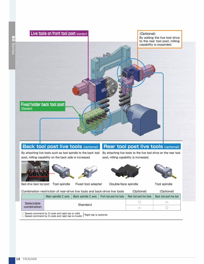
By attaching live tools such as tool spindle to the back tool post, milling capability on the back side is increased.
By attaching live tools to the live tool drive on the rear tool post, milling capability is increased.
By adding the live tool drive to the rear tool post, milling capability is expanded.
○: Speed command by S code and rigid tap is valid△: Speed command by S code and rigid tap is invalid}Rigid tap is optional.
Selectable combination
Standard
Main spindle C axis Back spindle C axis Front tool post live tools Rear tool post live tools
○
△
Back tool post live tool
△
○
(Optional) (Optional)Combination restriction of rear-drive live tools and back-drive live tools
Back drive (back tool post) Tool spindleDouble-face spindle
Back tool post live tools (optional)
(Optional)
Fixed holder back tool post(Standard)
Live tools on front tool post (standard)
Rear tool post live tools (optional)
Fixed tool adapterTool spindle
18
B0
Se
ries

Options
External illumination lightA light, which illuminates tooling zone.
Rear drive (Rear tool post)Base unit to mount the live tools on the rear tool post.
Work catcherThe workpiece discharged from back spindle is collected by a catcher, and carried out to the machine right outside through work conveyor.
Work conveyorAfter receiving the parted-off workpiece from the main spindle or the ejected workpiece from the back spindle with a catcher, it is carried out with a conveyor to outside of the machine.
Mist collectorOily or Water-soluble mist from the cutting area can be collected, and working environment is kept cleanly.
Front discharge (Oil blow / Air blow)An ejector ejects the workpiece from inside of the back spindle.
Coolant flow switchWhen the flow rate of coolant decreases, the machine will be stopped.The risk of fire or defective machining due to coolant shortage is limited.
Back drive (Back tool post)Base unit to mount the live tools on the back tool post.
High pressure pump (1500 W)When the optional M-code oil blow or workpiece front discharge unit is in use, employ this pump system together.
B0385B0385L
B0 Series 19
B0
Se
ries
B0385 B0385L

■Automatic cutting-off/facing
■Tool-height compensation function
Cutting-off or facing program is simplified with minimum imputing.
In this manner cutting-off or facing is simply executed. Moreover, same operation can be performed by the dedicated program code.
Execute tryout turning including bigger OD and smaller OD, and measure the both dimensions. On the dedicated screen by inputting the measured value and other data and pressing "CLAC" button, the compensation value is easily created. By pressing "UPDATE" soft key, the tool height offset data will be updated.
■Automatic cutting-off/facing
Cutting-off or facing program is simplified with minimum imputing.
Easy-to-use software
Cutting-off or facing is executed by inputting on the dedicated screen.Inputting tool number, offset number, bar diameter, spindle speed and feedrate, and by pressing start soft key:
Coolant ON, Spindle rotation ON
Approaching
Cutting-off/facing
Cutting-off Facing
20
B0
Se
ries

■Periodical maintenance
Rich information for the maintenance helps the effective operation
■Function setting
■C-axis selection (NC:0i-TD)
Useful maintenance information such as amount of lubrication oil, cleaning of chuck/guide bush, or battery replacement timing is displayed, contribute to the consistent maintenance. Items or setting period can be customized, and it can be optimized.
ON/OFF selection of various options such as work discharge, HP coolant, spindle indexing can be easily set on the dedicated screen.
C-axis applying path can be selected by the soft key.MAIN: C-axis is applied on the main spindle side.BACK: C-axis is applied on the back spindle side.
B0 Series 21
B0
Se
ries
B0385 B0385L

Creating NC program in two steps
SStteepppp222
SStteepppp11NC
program
Cycle time
3D simulation
Geometrical data inputting
Tool data inputting
Automatic generation
From program generation to simulation by simple operation
■Tsugami's rich know-how such as machining processes, machining conditions, etc. are taken into the software, and any novice programmers can create standardized and high quality programs.
Windows XPWindows VistaWindows 7 Internet Explorer 6.0 or more and Open GL library has installed.PC/AT compatibles (DOS/V machines)Intel Celeron 2GHz or faster (3GHz or more recommended)512MB or more100MB or more free space requiredDouble speed or more ( Used at installation)16.77 million color bit display (Full color) Resolution: 1024 x 768 or higher
Applicable models
Hardware requirementB03-Ⅱ Abile B073-Ⅱ/B0123-Ⅱ/B0203-Ⅱ/BM163-ⅡB04-Ⅱ Abile B074-Ⅱ/B0124-Ⅱ/B0204-Ⅱ/BM164-ⅡB05-Ⅱ Abile B0125-Ⅱ/B0205-Ⅱ/B0165-ⅡB06-Ⅱ Abile B0126-Ⅱ/B0206-ⅡB02632-Ⅱ Abile B0265-Ⅱ/B0265B-Ⅱ/B0266-Ⅱ/B0325-Ⅱ/B0325B-Ⅱ/B0326-ⅡB0385 Abile B0385/B0385L
Abile [B0]Series lineupItem Specifications
ComputerCPUMemoryHDDCD-ROM driveDisplay
OS
22
B0
Se
ries
B0 series automatic programming system "Abile".
B03-ⅡAbileB04-ⅡAbileB05-ⅡAbile
B02632-ⅡAbileB06-ⅡAbileB0385Abile
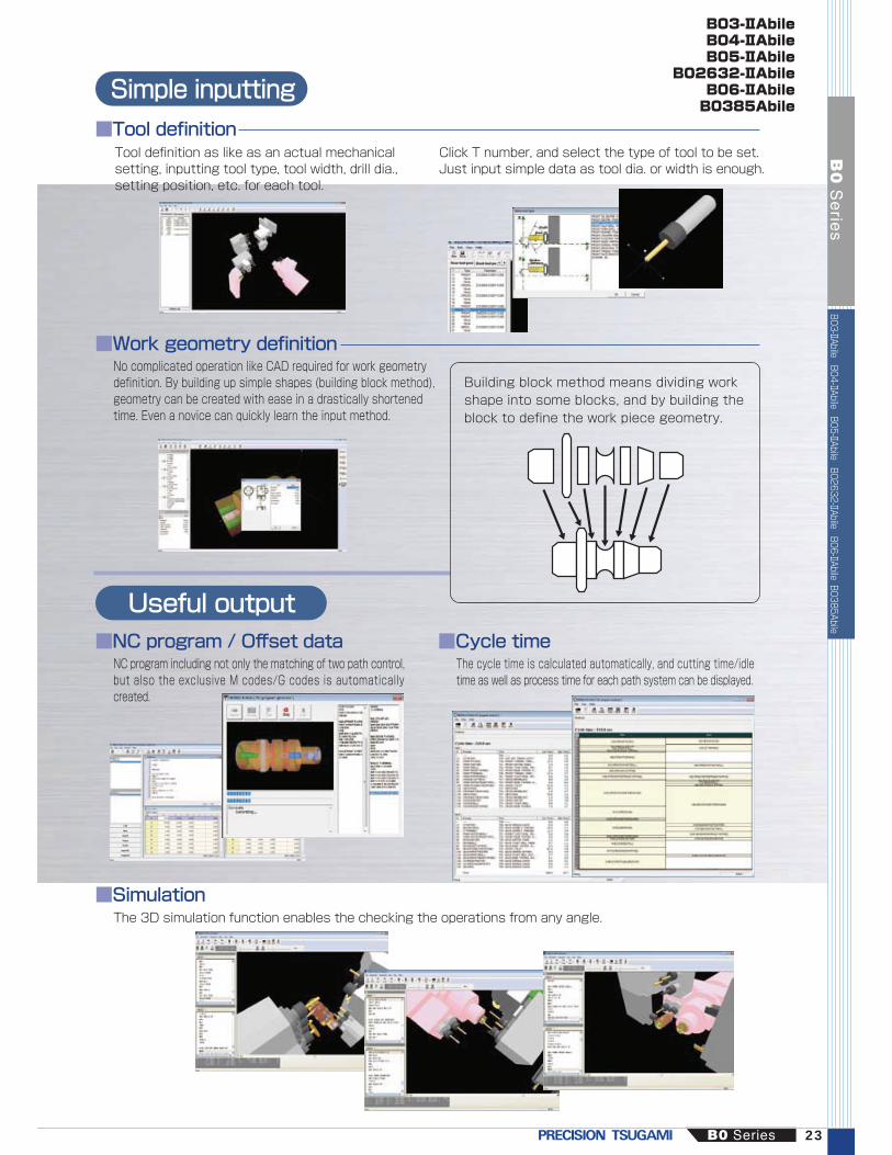
Simple inputting
Useful output
Tool definition as like as an actual mechanical setting, inputting tool type, tool width, drill dia., setting position, etc. for each tool.
Click T number, and select the type of tool to be set.Just input simple data as tool dia. or width is enough.
No complicated operation like CAD required for work geometry definition. By building up simple shapes (building block method), geometry can be created with ease in a drastically shortened time. Even a novice can quickly learn the input method.
NC program including not only the matching of two path control, but also the exclusive M codes/G codes is automatically created.
The 3D simulation function enables the checking the operations from any angle.
The cycle time is calculated automatically, and cutting time/idle time as well as process time for each path system can be displayed.
Building block method means dividing work shape into some blocks, and by building the block to define the work piece geometry.
■Tool definition
■Work geometry definition
■NC program / Offset data
■Simulation
■Cycle time
B03-ⅡAbileB04-ⅡAbileB05-ⅡAbile
B02632-ⅡAbileB06-ⅡAbileB0385Abile
B0 Series 23
B0
Se
ries
B03-ⅡAbile B04-ⅡAbile B05-ⅡAbile B02632-ⅡAbile B06-ⅡAbile B0385Abile

The guidance of the machine selection
Start
The machine selection should be defined by the current workpiece demand such as bar diameter or machining area, and expecting workpieces in future.B0 series can be divided into 4 categories. The selection flow is as follows:
Including milling operation?
(Note 1)
Is it a micro parts less than
7 mm dia?
Should milling operation be made by modular tools?
(Note 2)
24
B0
Se
ries
No
No
Yes
Yes
Yes
(Note 1) Milling, drilling or tapping by the tool spindle(Note 2) By replacing the cartridge type tool spindle, various operation such as milling, angular drilling, hobbing or thread whirling is possible.(Note 3) Replaceable tool spindle
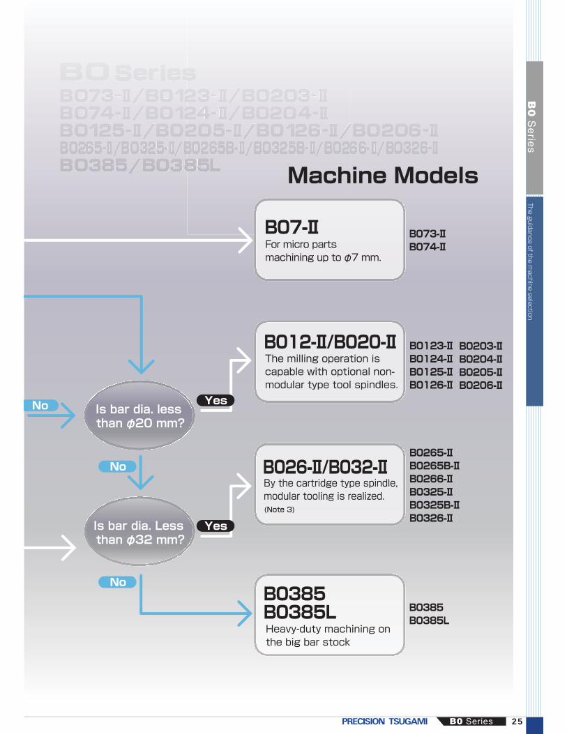
Is bar dia. less than φ20 mm?
Is bar dia. Less than φ32 mm?
B0 Series 25
B0
Se
ries
Yes
Yes
No
No
No
B07-ⅡFor micro parts machining up to φ7 mm.
B012-Ⅱ/B020-ⅡThe milling operation is capable with optional non-modular type tool spindles.
B026-Ⅱ/B032-ⅡBy the cartridge type spindle, modular tooling is realized.(Note 3)
B0385B0385LHeavy-duty machining on the big bar stock
B073-ⅡB074-Ⅱ
B0385B0385L
B0123-ⅡB0124-ⅡB0125-ⅡB0126-Ⅱ
B0203-ⅡB0204-ⅡB0205-ⅡB0206-Ⅱ
Machine Models
The guidance of the machine selection
B0265-ⅡB0265B-ⅡB0266-ⅡB0325-ⅡB0325B-ⅡB0326-Ⅱ

Standard Specifications of Machine
NC Specifications
Item
Item
B073-Ⅱ
B073-Ⅱ/B0123-Ⅱ/B0203-Ⅱ B074-Ⅱ/B0124-Ⅱ/B0204-Ⅱ B0125-Ⅱ/B0205-Ⅱ B0126-Ⅱ/B0206-Ⅱ
Machine capacity, M
achining rangeMachine
Motors
Power supply and others
Working barstock diameter
Max. machining length
φ1 to φ7 mm
Max. main spindle drilling diameterMax. main spindle tapping diameterMax. back spindle chucking dia.Max. back spindle drilling diameterMax. back spindle tapping diameterMax. cross drilling diameterMax. cross tapping diameterMax. tool spindle slotting cutter dia.Max. back drilling diameterMax. back tapping diameterMain spindle speedBack spindle speed*
NC unitControlled axesLeast input incrementLeast command incrementMaximum programmable valueInterpolation methodRapid traverse rateFeedrateFeedrate overrideDwell
Tool offset valueTool offset pairsLCD/MDIDisplay languagePart program storage sizeRegisterable programsMiscellaneous functionsSpindle functionTool function
ABS/INC command
φ4M4 x 0.7φ7ーー
φ4 (Op.)M4 x 0.7 (Op.)
ーーー
200 to 15,000 min-1
ー
FANUC 0i-TD FANUC 32i-BX1,Z1,Y1,X2,Z2,Y2,C1,C20.001 mm (X1/X2 axis in diameter)0.001 mm (X1/X2 axis in diameter)
±8 digitsLinear, circular
32 m/min (X1,Y1,Y2: 24 m/min)1 to 6,000 mm/min
0 to 150 % in 10 % incrementsG04 0 to 99999.99X,Y,Z,C: absolute, U,V,W,H: IncrementalX,Y,Z: absolute, U,V,W: Incremental
0.001 mm (X in diameter) (B073/74-Ⅱ: 0.0001 mm)X: 0.0005 mm, other axes: 0.001 mm (B074-Ⅱ: 0.00005 mm, other axes: 0.0001 mm)
±8 digitsLinear, circular
32 m/min (X1: 24 m/min)1 to 6,000 mm/min
0 to 150 % in 10 % incrementsG04 0 to 99999.99
±6 digits64
8.4”color LCDJapanese/English
M5-digitsS5-digitsT4-digits
512 k byte (equivalent to 1,280 m tape for each path system)400
1 Mbyte (equivalent to 2,560 m tape for each path system) *sum of main and back spindle NCs800 *sum of main and back spindle NCs
70 mm (40 mm (Carrier type rotary guide bushing)/70 mm (Direct-drive rotary guide bushing))
B074-Ⅱ B0123-Ⅱ B0124-Ⅱ B0203-Ⅱ B0204-Ⅱ
φ1 to φ7 mm φ3 to φ12 mm φ3 to φ20 mm
ーーー
1,400 kg7 kVA
1,700 kg10 kVA
1,400 kg7 kVA
1,700 kg10 kVA
1,640 x 1,035 x 1,700 1,640 x 1,080 x 1,700 1,640 x 1,035 x 1,700 1,640 x 1,080 x 1,700
ー ー ーーー
ー
φ12φ7M8 (Ⅱ)
ー 200 to 12,000 min-1
φ7M6 x 1
ーーー
φ20φ8M8 (Ⅱ)
ー 200 to 12,000 min-1
φ10M10 (Ⅱ)
210 mm (80/170 mm: (Rotary guide
φ6 (Op.)M5 x 0.8 (Op.)
200 to 12,000 min-1
12 mm x 12 mm x 85 mm
1.5/2.2 kW 2.2/3.7 kW
32 m/min (X1: 24 m/min)
0.4 MPa or above30 NL/min115 L
200 to 10,000 min-1
φ4M4 x 0.7φ7φ4
M4 x 0.7φ4 (Op.)
M4 x 0.7 (Op.)ーーー
200 to 15,000 min-1
200 to 10,000 min-1
3-axis
X1,Z1,Y1 X1,Z1,Y1,Z2 X1,Z1,Y1,X2,Z2
4-axis 3-axis 4-axis
ー 1.5/2.2 kW ー 1.5/2.2 kW0.5 kW (X1,X2,Y1,Z1,Z2)
0.5 kW (Op.)0.18 kW3 W
Tool spindle speedTotal tool storage capacity (Standard / Max.: Op.)Tool sizeRapid traverse rateControlled axes (linear axes)Main spindleBack spindleAxisCross drillCoolant pumpLubricating oil pumpNet weightPower source requirmentCompressed air requirementAir discharge rateCoolant tank capacityWidth x depth x height
200 to 5,000 min-1 (op.)17
8 mm x 8 mm x 85 mm32 m/min (X1: 24 m/min)
4-axis1.1/1.5 kW0.55/1.1 kW
0.5 kW (X1,X2,Y1,Z1,Z2)0.5 kW (Op.)0.18 kW3 W
1,700 kg9 kVA
0.4 MPa or above30 NL/min115 L
1,640 x 1,080 x 1,700
200 to 5,000 min-1 (op.) 200 to 5,000 min-1 (op.)13 17 13 17
Rotary guide bushing speed 200 to 8,000 min-1: Carrier type/200 to 15,000 min-1: Direct-drive
200 to 5,000 min-1 (op.)13
8 mm x 8 mm x 85 mm32 m/min (X1: 24 m/min)
3-axis1.1/1.5 kW
ー0.5 kW (X1,Y1,Z1)0.5 kW (Op.)0.18 kW3 W
1,400 kg6 kVA
0.4 MPa or above30 NL/min85 L
1,400 x 1,035 x 1,700
200 to 8,000 min-1:Carrier type rotary guide bushing/200 to 12,000 min-1:Direct-drive rotary guide bushing
200 to 8,000 min-1:Carrier type rotary guide bushing/200 to 10,000 min-1:Direct-drive rotary
±6 digits99
10.4”color LCDJapanese/English
64 kbyte (equivalent to 80m for each path system)63 *sum of main and back spindle NCs
M5-digitsS5-digitsT4-digits
26
B0
Se
ries
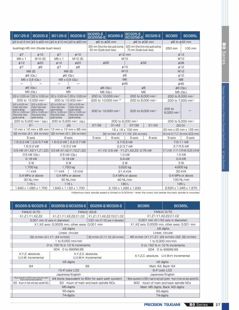
B0265-Ⅱ/B0325-Ⅱ B0265B-Ⅱ/B0325B-Ⅱ B0266-Ⅱ/B0326-Ⅱ B0385 B0385L
FANUC 0i-TDX1,Z1,Y1,X2,Z2 X1,Z1,Y1,X2,Z2,C1,C2
0.001 mm (X axis in diameter)
FANUC 0i-TDX1,Z1,Y1,X2,Z2,C1,C2
0.001 mm (X1/X2 axis in diameter)X1,X2 axis: 0.0005 mm, other axes: 0.001 mm
±8 digitsLinear, circular
45 m/min (X1,Y1,Z1: 24 m/min) (X2: 32 m/min)1 to 6,000 mm/min
0 to 150 % in 10 % incrementsG04 0 to 99999.99
±6 digitsMain: 64, Back: 648.4”color LCDJapanese/English
1 Mbyte (equivalent to 2,560 m tape for each path system) *sum of main and back spindle NCs800 *sum of main and back spindle NCs
Main: M5 digits, Back: M3 digitsS5-digitsT4-digits
X,Y,Z: absolute, U,V,W: Incremental
X,Y,Z,C: absolute, U,V,W,H: Incremental
32 m/min (X1,Y1: 24 m/min) 32 m/min (X1,Y1,Y2: 24 m/min)
FANUC 32i-BX1,Z1,Y1,X2,Z2,Y2,C1,C20.001 mm (X1/X2 axis in diameter)
800 *sum of main and back spindle NCs64 kbyte (equivalent to 80m for each path system)
63 *sum of main and back spindle NCs
64 99
B0125-Ⅱ B0205-Ⅱ B0126-Ⅱ B0206-Ⅱ B0266-Ⅱ B0326-Ⅱ
φ3 to φ12 mm φ3 to φ20 mm φ3 to φ12 mm φ3 to φ20 mm φ8 to φ26 mm φ8 to φ32 mm
B0385 B0385L
φ8 to φ32 mm
250 mm 100 mm
φ26 φ32
φ13M12φ38φ12M12φ10M8φ45
φ8 (Op.)M6 (Op.)
200 to 6,000 min-1
200 to 7,000 min-1
200 to 5,000 min-1
20/3120 mm x 20 mm x 125 mm45 m/min (X1,Y1,Z1: 24 m/min) (X2:32 m/min)
200 to 6,000 min-1
200 to6,000 min-1
7.5/11 kW3.7/5.5 kW
Z1:1.2 kW, X1,Y1: 0.75 kW, X2,Z2: 2.5 kW1.0 kW0.4 kW3 W
4,600 kg30 kVA
0.4 MPa or above100 NL/min195 L
2,520 x 1,345 x 1,970
φ8 (Op.)M6 (Op.)
200 to 10,000 min-1
200 to 10,000 min-1*
φ8M6
200 to 8,000 min-1
200 to 8,000 min-1
ー ー ー ー
ー
φ7M6 x 1φ12φ7
1.5/2.2 kW 2.2/3.7 kW 1.5/2.2 kW 2.2/3.7 kW
11 kVA 12 kVA
M8 (Ⅱ)φ6 (Op.)
M5 x 0.8 (Op.)
2112 mm x 12 mm x 85 mm32 m/min (X1: 24 m/min)
5-axis
12 mm x 12 mm x 85 mm32 m/min (X1: 24 m/min)
6-axis
1.5/2.2 kW0.5 kW (X1,X2,Y1,Z1,Z2)
0.5 kW (Op.)0.18 kW3 W
1,700 kg11 kVA
0.4 MPa or above30 NL/min115 L
1,640 x 1,080 x 1,700
M8 (Ⅱ)φ6 (Op.)
M5 x 0.8 (Op.)
φ6 (Op.)M5 (Op.)
φ6M5
27/39 31/43 27/39 31/43
5-axis 6-axis 5-axis 6-axis 5-axis 5-axis
1.5/2.2 kW0.5 kW (X1,X2,Y1,Y2,Z1,Z2)
0.5 kW (Op.)0.18 kW3 W
1,750 kg
0.4 MPa or above30 NL/min115 L
1,640 x 1,120 x 1,700
φ10M10 (Ⅱ)φ20φ8
φ7M6 x 1φ12φ7
φ10M10 (Ⅱ)φ20φ8
φ12 mmM10
16 x 16 x 100 mm32 m/min (X1,Y1,Y2: 24 m/min)
200 to 10,000 min-1 200 to 8,000 min-1
3.7/5.5 kW2.2/3.7 kW
X1,Y2: 0.5 kW Y1,Z1,X2,Z2: 0.75 kW1.0 kW0.4 kW3 W
3,500 kg21.4 kVA
0.4 MPa or above40 NL/min180 L
2,150 x 1,280 x 1,930
φ10M10φ8M6φ45
bushing)/45 mm (Guide bush less))
200 to 12,000 min-1 200 to 12,000 min-1
320 mm (Direct-drive rotary guide bushing)50 mm (Guide bush less)
320 mm (Direct-drive rotary guide bushing)70 mm (Guide bush less)
±8 digitsLinear, circular
X1,X2 axis: 0.0005 mm, other axes: 0.001 mm
M5-digitsS5-digitsT4-digits
10.4”color LCDJapanese/English
±6 digits
X,Y,Z,C: absolute, U,V,W,H: Incremental
1 to 6,000 mm/min0 to 150 % in 10 % increments
G04 0 to 99999.99
200 to 12,000 min-1 200 to 10,000 min-1 200 to 12,000 min-1 200 to 10,000 min-1
200 to 5,000 min-1 (op.) 200 to 5,000 min-1 (op.)25
200 to 8,000 min-1:Carrier type rotary guide bushing/200 to 12,000 min-1:Direct-drive rotary guide bushing
200 to 8,000 min-1:Carrier type rotary guide bushing/200 to 10,000 min-1:Direct-drive rotary guide bushing
200 to 8,000 min-1:Carrier type rotary guide bushing/200 to 12,000 min-1:Direct-drive rotary guide bushing
200 to 8,000 min-1:Carrier type rotary guide bushing/200 to 10,000 min-1:Direct-drive rotary guide bushing
※Maximum back spindle speed is limited to 8,000min-1 when the rotary tool beside the back spindle is mounted.
1 Mbyte (equivalent to 2,560 m tape for each path system)*sum of main and back spindle NCs
B0265-ⅡB0265B-Ⅱ
B0325-ⅡB0325B-Ⅱ
B0 Series 27
B0
Se
ries
Standard Specifications of Machine (Standard Specifications)
NC Specifications

Standard Accessories
Item
*: B073-Ⅱ/B0123-Ⅱ/B0203-Ⅱ: Main spindle only
Automatic programming systemTool height compensationTool life counterPeriodic maintenance screenMain spindle adapterBack spindle adapterGuide bushing adapterDoor interlockCoolant level detectorSpindle cooling unitStandard toolsTransit clamps4-hole drill bracketRetractable coolant nozzleAutomatic power shut offFront tool post: 4-spindle cross drillDeep hole drill holder (φ25mm×2)Automatic cut-off function/Automatic facing functionMain spindle/back spindle air purgeCross drill air purgeMain spindle brakeC-axis control for main/back spindles
NC standard accessories
Item
Chasing functionContinuous thread cuttingManual pulse generatorMemory card input/output interfaceBack ground editingRun time & parts number displayCustom macroConstant surface speed controlSpindle synchronous control (rotation/phase/tracing)Tool geometry/wear offsetProgrammable data inputChamfering & corner RTool nose radius compensationHRV controlMultiple repetitive cycleExtended program editingCanned drilling cycleRigid tap (Main spindle, back spindle)Spindle speed fluctuation detectionCut-off detection (Speed Differential type)Manual handle retrace functionStored stroke check 2,3
○○○○○○○○ー○○○○○○○○○*○ーーー
○○○○○○○○○○○○○○○○○○○○ーー
○○○○○○○○○○○○○○○○○○○○ー○
○○○○○○○○○○○○○○○○○○○○○ー
○○○○○○○○○○○○○○○○○○○○○ー
○○○○○○○○○○○○○○○○○○○○ーー
B073-ⅡB0123-ⅡB0203-Ⅱ
B0385 B0385LB0126-ⅡB0206-Ⅱ
B0265-Ⅱ/265B-Ⅱ/266-ⅡB0325-Ⅱ/325B-Ⅱ/326-Ⅱ
B074-Ⅱ/124-Ⅱ/125-ⅡB0204-Ⅱ/205-Ⅱ
B073-ⅡB0123-ⅡB0203-Ⅱ○○○○○ーー○○○○○○○○ーー○ーーーー
○○○○○○ー○○○○○○○○ーー○ーーー○
○○○○○○ー○○○○○ー○○○○○○○○ー
○○○○○○ー○○○○○ー○○○○○○○○○
○○○○○○○○○○○○ー○○○ーー○○○○
○○○○ー○ー○○○○○ー○○○ーー○○○○
○○○○○○ー○○○○○○○○ーー○ーーーー
B0385 B0385LB0126-ⅡB0206-Ⅱ
B0265-ⅡB0325-Ⅱ
B0265B-Ⅱ/325B-ⅡB0266-Ⅱ/326-Ⅱ
B074-Ⅱ/124-Ⅱ/125-ⅡB0204-Ⅱ/205-Ⅱ
28
B0
Se
ries

*1: Can not be mounted on B0123-Ⅱ and B0203-Ⅱ. *2: Standard for 3-axis machine (without back spindle)*3: B0125-Ⅱ/B0205-Ⅱ only *4:Brake is optional.
Stationary guide bushingCarrier type rotary guide bushingDirect-drive guide bushingGuide-bushing-less kitMain spindle C axis controlBack spindle C axis control(Brake is optional)Spindle 15°indexMain spindle brakeBack spindle 15°indexBack spindle 1°indexLive tool beside the back spindle3-spindle cross drill4-spindle cross drill0.1 μm resolutionCoolant oil temperature controllerRear driveTool spindleDouble face spindleAngular drilling headThread whirling headHobbing headBack driveTool spindleBack cross tool spindleBack tool adapterMist collectorHigh pressure pump unitM code oil blowWork catcherWork conveyorFront dischargeRear dischargeChip conveyorCut-off detection (Touch switch type)Signal indicatorAdapter for non-round bar (main spindle)Adapter for non-round bar (back spindle)Collet chuck with carbide liningTool set gaugeSpindle linerDrill holderPart program storage size 128 k bytesPart program storage size 256 k bytesPart program storage size 512 k bytesG-code system B/CDirect drawing dimension programVariable-lead thread cuttingThread cutting cycle retractNumber of registerable programs expansion #1Standard program storage size: 120 programs128 KB : 250 programs256 KB : 500 programs512 KB : 1,000 programsPolar coordinate interpolationCylindrical interpolationDisplay languageCoolant flow switchAutomatic fire extinguisherIllumination lampBar feeder interfaceManual handle retrace functionLive tool rigid tappingRS232C input/output interfaceInch/metric conversionAbnormal load detection
Options
Item B074-Ⅱ B0385 B0385LB0126-ⅡB0206-Ⅱ
B073-Ⅱ B0265-ⅡB0325-Ⅱ
B0265B-ⅡB0325B-Ⅱ
B0266-ⅡB0326-Ⅱ
B0123-Ⅱ/124-Ⅱ/125-ⅡB0203-Ⅱ/204-Ⅱ/205-Ⅱ
Guide bushing
Advanced function system
Coolant related
Workpiece discharge system
Tooling related
NC functions
Safety and other
Machine maintenance and monitoring functions
Chip disposal
High precision system
Live tools (Rear tool post)
Live tools (Back tool post)
standard○○
○○○○○○
○○
standard○
○○○
standard
○○○○○○○○○○
standardstandardstandard
○○○○○○○○○○○○
○○○○
standard*4standard○○○○
○○○○
standardstandardstandard
○○○○○○○○○○○○○○○
○○○○○○○○○○○○○○○○○○○○○○○○
standard○○
○
○○
○○
standard○
standard
○○○
○○○
standardstandardstandard
○○○○○○○○○○○○
standardstandard
standard
○
standard○○○○○○
○○
○○○○○○○○○
○○○○○○○
standardstandardstandard
standard○○○○○○
standard○○○○
standardstandardstandard
standard
○
standard○○○○○○
○○
○○○○○○○○○
○
○○○○○
standardstandardstandard
standard○○○○○○
standard○○○○
○○○○
standard○○○
standard○○○○○○○○○○
○○○○○○○○○
○○○○○○○
○standardstandardstandard
standardstandard○○○○○○○○○○
○○
standardstandard
standard○○○
standard○○○○○○○○
standard○○○○○○○○○○○
○○○○○○○○○○○○○○○○○○○○○○○○○○○○○○○
○○
standardstandard
standard○○○
standard○○○○○○○○○○
○○○○○○○○○
○○○○○○○○○○○○○○○○○○○○○○○○○○○○○○○
○○○○○○*1○○○*1○*1
○○○○
○*3
○*3
○○○○*2○*1○*1○*1○*1○○○○○○○
standardstandardstandard
○○○○○○○○○○○○
B0 Series 29
B0
Se
ries
Standard A
ccessories NC standard accessories O
ptions
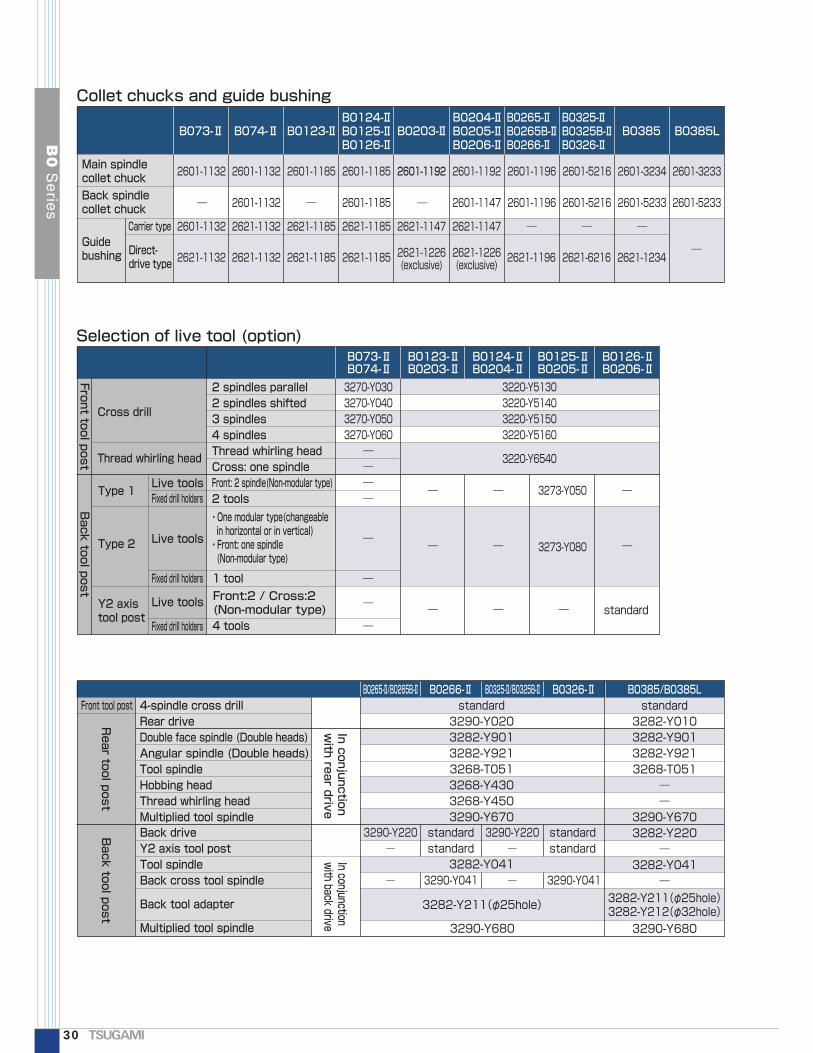
Collet chucks and guide bushing
B073-Ⅱ B074-Ⅱ B0123-Ⅱ B0203-Ⅱ B0385 B0385L
2601-1132
2601-1132
2621-1132
2601-1132
2601-1132 2601-1185
2601-1185
―
― ― ―
――
―
―
―
―
― ― ―
―
2621-1132 2621-1185 2621-1185
2621-1132 2621-1185
2601-1185
2621-1185
2601-1196
2601-1196
2621-1196
3220-Y51303220-Y51403220-Y51503220-Y5160
3220-Y6540
3270-Y0303270-Y0403270-Y0503270-Y060――――
2601-5216
2601-5216
2621-6216
2601-5233
2601-3234
2621-1234
2601-5233
2601-3233
―
―
2601-1192
2621-1147
2621-1226(exclusive)
2621-1226(exclusive)
2601-1192
2601-1147
2621-1147 ― ― ―
―
B0124-ⅡB0125-ⅡB0126-Ⅱ
B0204-ⅡB0205-ⅡB0206-Ⅱ
Main spindle collet chuck
Guide bushing Direct-
drive type
Carrier type
Back spindle collet chuck
Selection of live tool (option)B0126-ⅡB0206-Ⅱ
B0124-ⅡB0204-Ⅱ
B0123-ⅡB0203-Ⅱ
B073-ⅡB074-Ⅱ
B0125-ⅡB0205-Ⅱ
Front tool post
Rear tool post
In conjunction with rear drive
In conjunction with back drive
Back tool post
Back tool post
Cross drill
2 spindles parallel2 spindles shifted3 spindles4 spindlesThread whirling headCross: one spindleFront: 2 spindle(Non-modular type)2 tools
4-spindle cross drillRear driveDouble face spindle (Double heads)Angular spindle (Double heads)Tool spindleHobbing headThread whirling headMultiplied tool spindle
・One modular type(changeable in horizontal or in vertical)・Front: one spindle (Non-modular type)
Front:2 / Cross:2 (Non-modular type)
Live toolsFixed drill holders
Live tools
Front tool post
Fixed drill holders
Fixed drill holders
Live tools
Type 1
1 tool
4 tools
Type 2
Y2 axis tool post
Thread whirling head
3273-Y080
standard
3273-Y050
B0265-Ⅱ/B0265B-Ⅱ B0266-Ⅱ B0326-Ⅱ B0385/B0385LB0325-Ⅱ/B0325B-Ⅱstandard3290-Y0203282-Y9013282-Y9213268-T0513268-Y4303268-Y4503290-Y670
standard3282-Y0103282-Y9013282-Y9213268-T051
――
3290-Y6703282-Y220
―3282-Y041
―3282-Y211(φ25hole)3282-Y212(φ32hole)3282-Y211(φ25hole)
3290-Y680
3282-Y041
3290-Y220―
standardstandard
3290-Y220―
―
standardstandard
― 3290-Y041 3290-Y041
3290-Y680
Back driveY2 axis tool postTool spindleBack cross tool spindle
Back tool adapter
Multiplied tool spindle
B0265-ⅡB0265B-ⅡB0266-Ⅱ
B0325-ⅡB0325B-ⅡB0326-Ⅱ
30
B0
Se
ries

210(Max. machining length))
6334 (B074-Ⅱ)
40 5035
84 1370 (Max. machining length) 80
B0124-Ⅱ/204-ⅡB0123-Ⅱ/124-Ⅱ/203-Ⅱ/204-Ⅱ
B073-Ⅱ/74-ⅡB074-Ⅱ
1Collet chuck end face
1170 (Stroke)
Reference tool position
(Max. machininglength)
63 40 50
3553
Collet chuck end face
2 13170 (Stroke)
Reference tool position
3003
88
42 (X1Stroke)(
221
28
38
2828
2828
28
2835
232323
160 (Stroke)
78 882020
T01
T02
T03
T04
T05
T06T16
T17
T15
T14T13T12T11
(Guide-bushing-less: B0123-Ⅱ/124-Ⅱ/203-Ⅱ/204-Ⅱ)
45(Max. machining length)
2 13
88
221
38
2828
2828
28
2828
35232323
160 (Stroke)
78 8820 20
4-φ20
T01
T02
T03
T04
T05
T06T16
T17
T15
T14T13T12T11
210(Max. machining length)
63 40
84
1
Guide bushing end face
Collet chuck end face
13
170 (Stroke)
Reference tool position
116
2828
28
200 (Stroke)
4-φ20
103
T31T32T33T34
63 40
Collet chuck end face
170 (Stroke)
Reference tool position
116
2828
28
200 (Stroke)
4-φ20
103
T31T32T33T34
(Guide-bushing-less)42 (X1Stroke)(
Guide bushing end face
B073-Ⅱ/74-Ⅱ/123-Ⅱ/124-Ⅱ/203-Ⅱ/204-Ⅱ
Tooling zone
B0125-Ⅱ/205-Ⅱ
B0 Series 31
B0
Se
ries
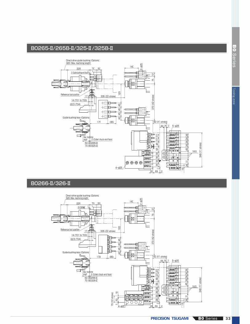
Collet chucks and guide bushing Selection of live tool (option) Tooling zone
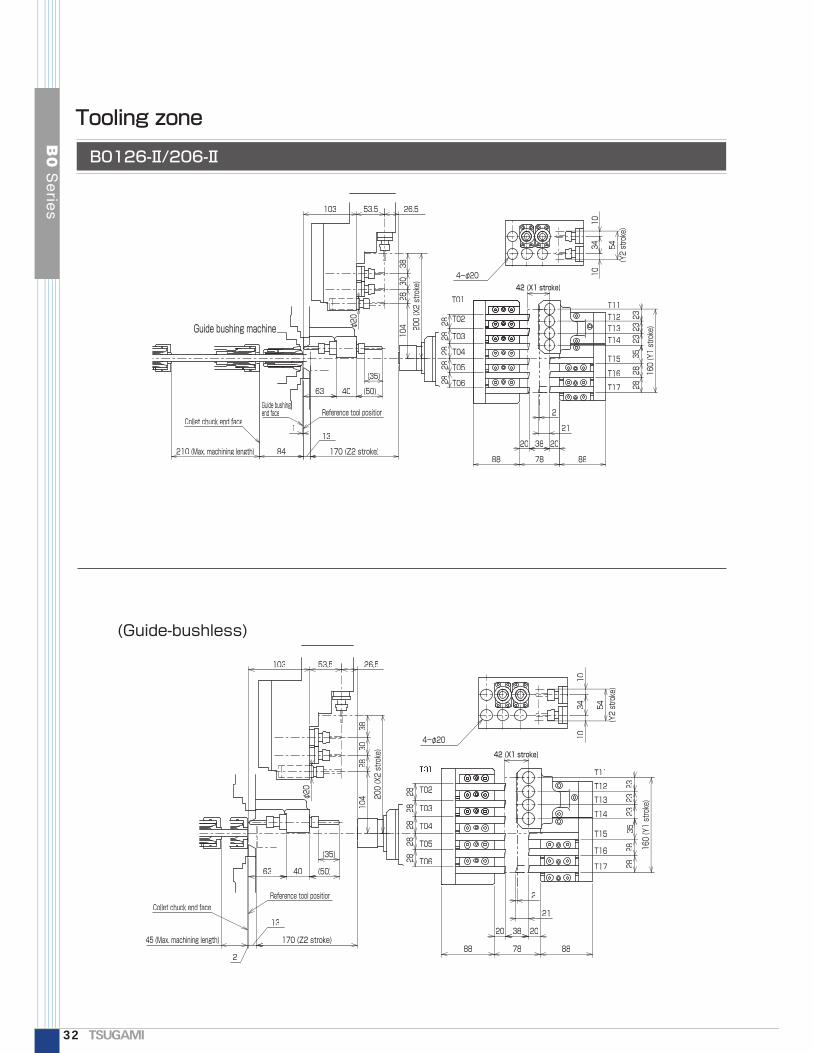
(Guide-bushless)
210 (Max. machining length)
2
21
63 40 (50)
(35))(
2884
1
Guide bushingend face
Collet chuck end face
2828
3523
2323
160 (Y1 stroke)
88
13
170 (Z2 stroke)20
2828
2828
3820
88 78
Reference tool position104
2830
38200 (X2 stroke)
103 53.5 26.5
φ20
1034
10
54(Y2 stroke)
Y
4-φ20
T02
T03
T04
T05
T06T16
T17
T15
T14T13T12T11T01
Guide bushing machine
45 (Max. machining length)
2
21
63 40 (50)
(35))(
28
2
Collet chuck end face
2828
3523
2323
160 (Y1 stroke)
88
13
170 (Z2 stroke)20
2828
2828
3820
88 78
Reference tool position
104
2830
38
200 (X2 stroke)
103 53.5 26.5
φ20
1034
10
54(Y2 stroke)
4-φ20
T02
T03
T04
T05
T06T16
T17
T15
T14
T13T12T11
42 (X1 stroke)(
42 (X1 stroke)
B0126-Ⅱ/206-Ⅱ
Tooling zone
32
B0
Se
ries
26
5-φ25
□16
3451
18.5453434343437
3748
5638
3838
38
69 2
44 25
348 (Y1 stroke)
142 (X1 stroke))
2
320 (Max. machining length)
3775
370 (X2 stroke)
4245
4545
193
50702292 (Guide bushing end face)
335 (Z2 stroke)
Max. machininghlength50 (B0265-Ⅱ)70 (B0325-Ⅱ)
14 (T01 to T03)22.5 (T04)
17
140
2-φ25
179 (85)
4-φ25
Reference tool position
2 (Collet chuck end face)
Direct-drive guide bushing (Options)
Guide-bushing-less (Options)
26
5-φ25
□16
3451
18.5
453434343437
3748
5638
3838
38
69 2
44 25
348 (Y1 stroke)
142 (X1 stroke))
2
320 (Max. machining length)
3775
370 (X2 stroke)
50702292(GB端)
335 (Z2 stroke)
Max. machininghlength50 (B0266-Ⅱ)70 (B0326-Ⅱ)
14 (T01 to T03)22.5 (T04)
17
140
2-φ25
Reference tool position
2 (Collet chuck end face)
502
18
70 (Y2 stroke)
4545
45
179 (85)
4-φ254
42193
Direct-drive guide bushing (Options)
Guide-bushing-less (Options)
B0265-Ⅱ/265B-Ⅱ/325-Ⅱ/325B-Ⅱ
B0266-Ⅱ/326-Ⅱ
B0 Series 33
B0
Se
ries
Tooling zone

69 692
3232
4848
4855
3939
358 (Y1 stroke)
69 2
142(X1 stroke))
3-φ32
2054
5454
5448
3737
Back tool post
5-φ32
370 (X2 stroke)
5050
5050
5012021 300 (Z2 stroke)
4980
2
96250(Max. machining length)ga
14 (T1 to T3)22.5 (T4)
80 90 15187 64
5-φ32
81
3-φ32
370 (X2 stroke)
5050
5050
5012021 300 (Z2 stroke)
4980
2
100x. machining length)n(Maxx
14 (T1 to T3)22.5 (T4)
80 90 15187 64
5-φ32
103020 5X2-M88
69 692
3232
4848
4855
3939
358 (Y1 stroke)
69 2
142 (X1 stroke)
2054
5454
5448
3737
Back tool post
5-φ32
81
Tooling zone
B0385
B0385L
34
B0
Se
ries

3,095
IKURA: OS121ET-12-2.5 m
440 1,035
3901,250300 1,640
5,035
1,000 1,700
225
(OP)
1,260 (OP)
High pressurepump unit (Option)
1701,4701,640
440 1,080
180
(OP)
1,260 (OP)
4003,830
5,870
IKURA: OS20T-3.0 m(Option)
High pressurepump unit (Option)
Work conveyor
1,000 1,700
(4,795: BO73-Ⅱ) (1,400: BO73-Ⅱ)(150: BO73-Ⅱ)B
Appearances
B074-Ⅱ/124-Ⅱ/125-Ⅱ/204-Ⅱ/205-Ⅱ/126-Ⅱ/206-Ⅱ
B073-Ⅱ/123-Ⅱ/203-Ⅱ
B0 Series 35
B0
Se
ries
Tooling zone
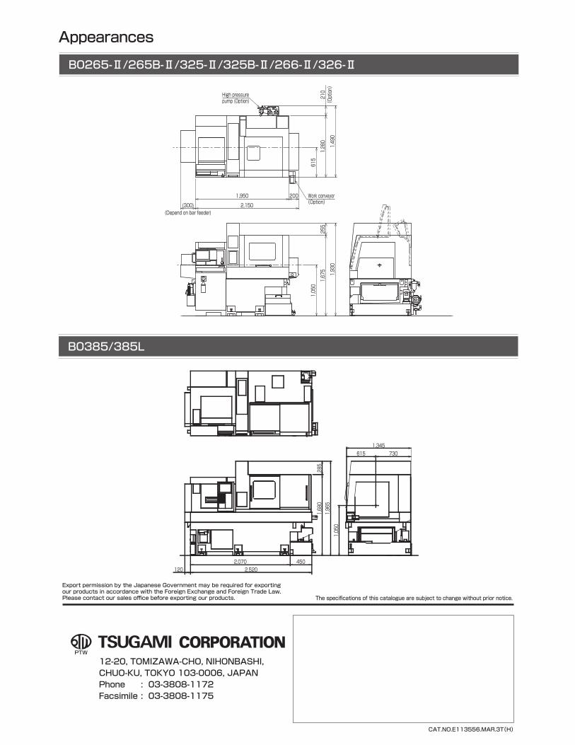
Appearances
B0265-Ⅱ/265B-Ⅱ/325-Ⅱ/325B-Ⅱ/266-Ⅱ/326-Ⅱ
B0385/385L
(300)(Depend on bar feeder)
1,950 200
2,150
Work conveyor(Option)
(Option)
High pressure pump (Option)
615
1,280
210
1,490
1,050
255
1,675 1,930
CAT.NO.E113556.MAR.3T(H)
2,5202,070 450
1,680
285
1,965
1,050
615 7301,345
120
Export permission by the Japanese Government may be required for exportingour products in accordance with the Foreign Exchange and Foreign Trade Law.Please contact our sales office before exporting our products. The specifications of this catalogue are subject to change without prior notice.
12-20, TOMIZAWA-CHO, NIHONBASHI, CHUO-KU, TOKYO 103-0006, JAPANPhone : 03-3808-1172Facsimile : 03-3808-1175


