Collaboration in Opportunistic Networks Vom Fachbereich Informatik der Technischen Universit¨ at Darmstadt genehmigte Dissertation zur Erlangung des akademischen Grades Doctor rerum naturalium (Dr. rer. nat.) von Dipl.-Inform. Andreas Heinemann geboren in Arolsen Referenten Prof. Dr. Max M¨ uhlh¨ auser (TU Darmstadt) Gerd Kort¨ um, Ph.D. (Lancaster University) Tag der Einreichung: 30.04.2007 Tag der m¨ undlichen Pr ¨ ufung: 04.06.2007 Darmstadt 2007 Hochschulkennziffer D17
Transcript
Collaboration inOpportunistic Networks
Vom Fachbereich Informatikder Technischen Universitat Darmstadt
genehmigte
Dissertation
zur Erlangung des akademischen GradesDoctor rerum naturalium (Dr. rer. nat.)
von
Dipl.-Inform. Andreas Heinemann
geboren in Arolsen
ReferentenProf. Dr. Max Muhlhauser (TU Darmstadt)Gerd Kortum, Ph.D. (Lancaster University)
Tag der Einreichung: 30.04.2007Tag der mundlichen Prufung: 04.06.2007
Darmstadt 2007Hochschulkennziffer D17
ii
Acknowledgements
This work would not have been possible without the continuous support and encour-agement of my colleagues and friends over the last years, which I would like toacknowledge here.
First and foremost I would like to thank my advisor, Max Muhlhauser, for hisfaith in my work and for giving me excellent advice on many issues concerning thiswork and beyond. Next, I am grateful to Gerd Kortum, for the fruitful discussionsconcerning this thesis and for acting as a second referee. In particular, his visit in2005 was an inspiring experience for me.
I am grateful to all at Telecooperation and RBG for providing me with a friendlyand supportive place to work. Special thanks go to Jussi Kangasharju for our regularmeetings and his valuable advice, and to Tobias Straub for reviewing and discussingnumerous aspects of this work with me.
It was a pleasure for me to co-author scientific publications with Erwin Aiten-bichler, Andreas Gorlach, Jussi Kangasharju, Fernando Lyardet, Max Muhlhauser,Johannes Ranke, Tobias Straub, Wesley W. Terpstra, and Marco Voss.
Thanks to the “Austrians,” Erwin Aitenbichler, Gerhard Austaller, and An-dreas Hartl for their open-door-policy, whenever I ran into problems concerningadministration and programming.
Many people improved this text with their reviews and comments. Thanks toJussi Kangasharju, Gerd Kortum, Max Muhlhauser, Guido Roßling, and TobiasStraub. Thanks to Lara Schwarz for editing the final version.
Finally, thanks to my parents, sisters, and friends, especially Annette Ebert, fortheir mental support and patience during the course of this work.
iii
iv CHAPTER 0. ACKNOWLEDGEMENTS
Abstract
Motivation. With the increasing integration of wireless short-range communica-tion technologies (Bluetooth, 802.11b WiFi) into mobile devices, novel applicationsfor spontaneous communication, interaction and collaboration are possible. We dis-tinguish between active and passive collaboration. The devices help users becomeaware of each other and stimulate face-to-face conversation (active collaboration).Also, autonomous device communication for sharing information without user in-teraction is possible, i.e., devices pass information to other devices in their vicinity(passive collaboration). Both, active and passive collaboration requires a user tospecify what kind of information he offers and what kind of information he isinterested in.
Object of Research: Opportunistic Networks. Spontaneous communication ofmobile devices leads to so-called opportunistic networks, a new and promisingevolution in mobile ad-hoc networking. They are formed by mobile devices whichcommunicate with each other while users are in close proximity. There are twoprominent characteristics present in opportunistic networks: 1) A user provides hispersonal device as a network node. 2) Users are a priori unknown to each other.
Objectives. Due to the fact that a user dedicates his personal device as a node tothe opportunistic network and interacts with other users unknown to him, collabo-ration raises questions concerning two important human aspects: user privacy andincentives. The users’ privacy is at risk, since passive collaboration applicationsmay expose personal information about a user. Furthermore, some form of incentiveis needed to encourage a user to share his personal device resources with others.
Both issues, user privacy and incentives, need to be taken into account in order toincrease the user acceptability of opportunistic network applications. These aspectshave not been addressed together with the technical tasks in prior opportunisticnetwork research.
Scientific Contribution and Evaluation. This thesis investigates opportunisticnetworks in their entirety, i.e., our technical design decisions are appropriate for userprivacy preservation and incentive schemes. In summary, the proposed conceptscomprise system components, a node architecture, a system model and a simpleone-hop communication paradigm for opportunistic network applications. Onefocus of this work is a profile-based data dissemination mechanism. A formal model
v
vi CHAPTER 0. ABSTRACT
for this mechanism will be presented. On top of that, we show how to preserve theprivacy of a user by avoiding static and thus linkable data and an incentive schemethat is suitable for opportunistic network applications.
The evaluation of this work is twofold. We implemented two prototypes onoff-the-shelf hardware to show the technical feasibility of our opportunistic networkconcepts. Also, the prototypes were used to carry out a number of runtime measure-ments. Then, we developed a novel two-step simulation method for opportunisticdata dissemination. The simulation combines real world user traces with artificialuser mobility models, in order to model user movements more realistically. Weinvestigate our opportunistic data dissemination process under various settings,including different communication ranges and user behavior patterns. Our resultsdepict, within the limits of our model and assumptions, a good performance of thedata dissemination process.
Zusammenfassung
Motivation. Mobile Endgerate sind zunehmend mit Technologien zur drahtlosenVernetzung uber kurze Distanz (bspw. Bluetooth, 802.11b WiFi) ausgestattet. Diesermoglicht neuartige Formen der spontanen Kommunikation, Interaktion und Kol-laboration. Hierbei wird zwischen aktiver und passiver Kollaboration unterschieden.Zum einen unterstutzen Gerate in Kommunikationsreichweite die Nutzer dabei, sichals potentielle Partner wahrzunehmen und sich gegebenenfalls zu einem spontanenGesprach (aktive Kollaboration) zusammenzufinden. Zum anderen konnen dieGerate autonom Informationen unter Nutzern verbreiten, sobald sich die Nutzer undsomit die Gerate in Kommunikationsreichweite befinden (passive Kollaboration).Fur die aktive wie passive Kollaboration teilt der Nutzer seinem Gerat mit, anwelchen Informationen er interessiert ist bzw. welche Informationen er weitergebenmochte.
Forschungsgegenstand: Opportunistische Netzwerke. Durch die spontane Ver-netzung mobiler Endgerate formieren sich opportunistische Netzwerke (engl. oppor-tunistic networks), die eine neue und vielversprechende Entwicklung auf dem Gebietder mobilen ad-hoc Netzwerke darstellen. Opportunistische Netzwerke weisen zweiwesentliche Merkmale auf: 1) Ein Nutzer stellt sein personliches Gerat partielldem Netzwerk zur Verfugung. 2) A priori agiert ein Nutzer mit ihm unbekanntenweiteren Teilnehmern des Netzwerkes.
Wissenschaftliche Fragestellung und Ziel. Der Einsatz von personlichen Gera-ten und die Interaktion mit unbekannten Teilnehmern innerhalb eines opportunis-tischen Netzes werfen Fragen zum Schutz der Privatsphare und zu Anreizen furdie Nutzer auf. Anwendungen, die passive Kollaboration unterstutzen, geben unterUmstanden personliche Informationen uber einen Nutzer preis und gefahrden sodessen Privatsphare. Des Weiteren erfordern opportunistische Netzwerk-Anwen-dungen eine Moglichkeit, dem Nutzer einen Anreiz zu verschaffen, damit diesersein personliches Gerat partiell der Gemeinschaft zur Verfugung stellt.
Beide Belange sind zu betrachten, um hinreichende Akzeptanz von Anwendun-gen in opportunistischen Netzen zu erreichen. In vorangegangenen Forschungs-arbeiten wurden der Schutz der Privatsphare und Anreize fur opportunistischeNetzwerke – zwei wichtige Aspekte aus Sicht der Nutzer – nicht gemeinsam mitden technischen Fragestellungen untersucht.
vii
viii CHAPTER 0. ZUSAMMENFASSUNG
Wissenschaftliche Beitrage der Arbeit und Evaluation. Als erster wissenschaft-licher Beitrag der Arbeit ist der gesamtheitliche Ansatz zu nennen: Die einzel-nen technischen Entwurfsentscheidungen berucksichtigen den Schutz der Privat-sphare und sind geeignet, Anreizsysteme zu unterstutzen. Diese Arbeit stellt hier-zu passende Konzepte und Verfahren vor. Insbesondere konzipiert diese ArbeitSystemkomponenten, eine Netzwerkknotenarchitektur, ein Systemmodell und eineinfaches one-hop Kommunikationsparadigma fur Anwendungen in opportunisti-schen Netzwerken und beschreibt deren Realisation sowie Evaluation. Hierbei liegtein Schwerpunkt der Arbeit auf einem abstrakten Modell fur profilbasierte Mecha-nismen zur Verbreitung von Informationen. Darauf aufbauend wird gezeigt, wiedie Privatsphare eines Nutzers mittels Verzicht auf statische Kommunikationsdatengeschutzt werden kann. Des Weiteren stellen wir ein Anreizsystem vor, das sich alsgeeignet fur opportunistische Netze erwiesen hat.
Die Evaluation gliedert sich in zwei Teile. Im ersten Teil werden zwei pro-totypisch realisierte Anwendungen auf Standard-Geraten vorgestellt. Die Proto-typen dienen zum Nachweis der technischen Umsetzbarkeit der hier vorgestelltenKonzepte und bilden die Plattform fur eine Reihe von Laufzeitmessungen, derenErgebnisse in dieser Arbeit vorgestellt werden. Der zweite Teil der Evaluationberuht auf einem Simulationsmodell fur die Verbreitung von Informationen inopportunistischen Netzen. Dieses Simulationsmodell stellt einen eigenstandigenoriginaren wissenschaftlichen Beitrag dar. Es verbindet aufgezeichnete Daten ausder realen Welt, die einen Ruckschluss auf die Nutzermobilitat erlauben, mit Bewe-gungsmodellen. Ziel ist es, die Bewegung von Nutzern realitatsnah zu modellieren.Mit Hilfe einer Implementierung des Simulationsmodells untersucht diese Arbeit inverschiedenen Szenarien die Geschwindigkeit bei der Informationsverbreitung. ImRahmen unserer Modellannahmen zeigt die Simulation eine gute Performanz beider Verbreitung von Informationen.
In 1991, Marc Weiser, at that time a researcher at Xerox PARC (Palo Alto ResearchCenter), formulated his vision of a new area in computer science and called itubiquitous computing [Wei91]. His vision promotes the idea of enabling peopleto move around and interact with computers more naturally than they currently do.Computers should become good, invisible tools. In his sense, an invisible tool is onethat does not draw the user’s attention towards itself. The user focuses on the task,not the tool. Weiser mentions eyeglasses as good tools. A user looks at the world,not the eyeglasses [Wei94]. Thus the tool disappears from the users’ awareness[Wei93a]. In an ubiquitous computing environment, a user is
continually interacting with hundreds of nearby wirelessly intercon-nected computers [Wei93b].
As a consequence, the idea of one or few personal computers per user has to begiven up. Computers vanish into the background, “allowing people to just go abouttheir lives” [Wei93b].
Another term that is closely related to ubiquitous computing is called pervasivecomputing. This term stresses more the idea of embedding computation power intothe environment and thus being imperceptible as computers anymore. According toLyytinen et al. [LY02], pervasive computing does not take node or user mobility intoaccount. Figure 1.1 (adapted from [LY02]) relates the terms mobile, pervasive andubiquitous computing to each other. Today, most people use pervasive computingas a synonym for ubiquitous computing.
The most prominent device that has conquered our everyday life and is basicallyubiquitously available is the mobile phone, though is has not become an invisibletool in Weiser’s sense. By the end of 2005, more than 810 million mobile phoneswere sold worldwide [Hei06]. In the top 5 economies in Europe (France, Germany,Italy, Spain, UK) on average 93,24 out of 100 inhabitants are subscribed to a mobilephone service [Int05].
Recently, more and more mobile phones (and other mobile devices, for ex-ample Personal Digital Assistants (PDAs) or laptops), are equipped with short
1
2 CHAPTER 1. INTRODUCTION
High
Low
HighLowLevel ofmobility
Level of Embeddedness
Traditionalcomputing
Ubiquitiouscomputing
Mobilecomputing
Pervasivecomputing
Figure 1.1: Traditional vs. pervasive vs. mobile vs. ubiquitous computing
range wireless communication capabilities (for Bluetooth module shipments in2005 see [Blu05]). In most cases, either Bluetooth [Blu03] or 802.11b WiFi technol-ogy [IEE99] is integrated into the devices. The prevalent use of wireless connectivityis to synchronize personal data between a mobile device and a desktop computer(using Bluetooth) or have easy access to an institution’s network (using 802.11 WiFiWireless Access Points) and further to the Internet.
However, with the integration of short range wireless communication technologyinto mobile devices, a new network type called opportunistic networks and itscorresponding applications based on spontaneous interaction and collaborationamong devices and users is possible. We illustrate its capabilities by setting word-of-mouth recommendation among colleagues in contrast to adPASS, an opportunisticnetwork application that disseminates advertisements among interested users.
Word-of-mouth recommendation: Alice and Bob are co-workerssharing the same office. On her way to work, Alice passes a shopwindow that announces a digital camera: 20% off the regular price.Alice knows that Bob plans to buy such a camera and tells him aboutthe advertisement when she arrives at her office. During lunch break,Bob visits the shop and buys the camera, glad that Alice has directedhis attention to the offer.
Word-of-mouth recommendation is a well known and established way of communi-cation and interaction among humans. There are two assumptions here: Alice andBob know each other’s interests in certain aspects of life and they meet on a regularbasis (or know how to contact each other) to share information. In addition, on herway to work, Alice needs to be wide awake in order to notice the shop-windowannouncement.
3
adPASS, an opportunistic network application developed as part of this thesismimics to some extent word-of-mouth recommendation.
adPASS: Alice carries a mobile device with her. A personal profile,stored on her device, holds information about her interests and knowl-edge. The device is able to match her profile with other nearby devicesby communicating wirelessly and without user interaction.
A shop has put a fixed device next to the shop window. This deviceannounces digital advertisements from the shop to passersby. As Alicepasses the shop window, her device learns about the special offer fordigital cameras.
Alice physically carries the advertisement with her and passes it furtherto other users she encounters. All users interested in the ad (includingherself and her colleague Bob) might take the chance and visit the shopin order to buy the advertised product.
adPASS differs from word-of-mouth recommendation in several ways: the userswho exchange advertisements do not need to know each other. A match in theirprofiles is sufficient to share the ads. Next, a user does not need to keep his attentionon the device. The device works without user interaction. Thus, Alice does not needto be wide awake in order to notice the ad.
In general terms, the following ideas are present in adPASS and other oppor-tunistic network applications that aim at user collaboration:
1) User and device vicinity exploitation: An obvious requirement for short rangecommunication is the co-location of users/devices at a certain time and place. Thisallows devices to pass information as illustrated by the adPASS example above.
Next, it raises the opportunity for users to meet face-to-face and make personalcontact. In addition, to some extent, the usefulness of an application increases, sincenearby users share the same physical context at a certain time and place. It is likelythat these users share a common interest. Even if this is not true for every encounter,close vicinity allows getting to know new people or simply to share information.
2) Profile-based user interest expression: After two devices have discoveredeach other, there needs to be a way to determine if it is beneficial for a deviceand thus its owner to communicate further. This is achieved by employing a userprofile on the device. A user profile expresses personal interest and knowledge.At the bottom line, a user wants to satisfy his interest and is committed to sharehis knowledge with other users. Therefore, an application needs a way to specifyinterest and knowledge and match interest against knowledge. This is a prerequisitefor disseminating data.
4 CHAPTER 1. INTRODUCTION
3) Data dissemination: Whenever knowledge of a user Alice is able to satisfyinterest of another user Bob by user profile matching, this knowledge is transferredfrom Alice to Bob. Given a number of users with the same interest, we observe aknowledge or data dissemination process. This process is additionally supported byuser mobility: users physically carry knowledge while they move around.
4) Unpredictable communication pattern: Communication and information ex-change takes place between mobile users that happen to be accidentally in commu-nication range. In other words, a user can not rely on these kinds of applications tosatisfy his interest. Therefore, questions like “What is the menu at the university’scafeteria for today?” or “What are the opening hours for the city hall?” are betteranswered by querying the Internet. Opportunistic networks simply offer a best effortfunctionality.
5) Open and unrelated user group: Apart from a few exceptions, most applica-tions do not make any assumption about their participating users. Thus, in general,users are unknown to each other, act independently, and might also act selfishly.
Looking at these ideas as a whole, collaboration in opportunistic networks raisestwo central questions in terms of user acceptability. First, can we preserve theprivacy of a user who uses adPASS or similar opportunistic network applications?Second, since a user makes its own personal device available to the opportunisticnetwork, can we come up with an incentive scheme in order to stimulate the user’sparticipation?
Privacy preservation and incentive schemes are two important human aspectspresent in opportunistic networks that have not been addressed together with thetechnical aspects in prior work. As we will see in the course of this thesis, thesehuman aspects influence the technical tasks. Herein lies the novelty of this work.For example, our proposed one-hop communication paradigm is fundamental foran adequate privacy preservation. Figure 1.2 illustrates the interrelation betweenhuman aspects and technical tasks. We have addressed these topics within this work:Algorithms and data modeling, communication and to some extend architectures foropportunistic networks. Not touched are resource management, for example, howto cope with limited memory or battery supply since the advances in these areasmake this less relevant, and UI design, being out of scope of this thesis.
Our results are of interest to all researchers working on opportunistic networksand related topics.
1.1 Objectives
The objectives of this thesis derive from the last section. One goal of this thesis isto formulate and define a system and communication model that is appropriate tointegrate privacy preservation and an incentive scheme. Since part of this work is
1.2 SCIENTIFIC CONTRIBUTION 5
psA en ca ts m u H H ust mc
ae
nps AA spna ecm tsu H
ResourceManagement
Architecture
Algorithm &Data
Modeling
UI Design
Communi-cation
Figure 1.2: Human aspects and technical tasks in opportunistic networks
inspired by word-of-mouth or gossip like data dissemination, these ideas should beeasily mapped onto our model.
Within the system model, a major aspect is the way data or information isexpressed. A solution should not constrain itself to a certain technology or program-ming language and it should be simple and easy to understand.
Finally, the solutions should prove its technical feasibility by means of per-formance measurements and real-world tests using prototype realizations and itseffectiveness should be validated by a data dissemination simulation.
1.2 Scientific Contribution
This thesis makes five contributions:
1) The first contribution is a system model for opportunistic networks. Themodel encompasses a communication model for data dissemination in op-portunistic networks. It is based on a one-hop communication paradigm.In addition, the system model introduces two fundamental data structures,namely iWish-list and iHave-list, to allow users to express their informationshares and needs to others. Within the model, nodes can be either mobile, i.e.,users carrying a mobile device, or fixed. Fixed nodes are called InformationSprinklers and support proximity based services.
2) The second contribution is a formal model for describing information andfilter objects that can be applied to the information. The formal model allowsus to formulate programming language independent algorithms for matchinguser profiles based on iWish- and iHave-lists.
6 CHAPTER 1. INTRODUCTION
3) The third contribution addresses the human aspects in opportunistic networks;as said before: user privacy preservation and an incentives scheme. In order topreserve user privacy, a mechanism based on dynamic and user-self-generatedaliases is described. An incentive scheme based on bonus points stimulatesuser participation in an opportunistic network. This contribution is alignedwith our system and communication model.
4) The fourth contribution is the successful implementation of two opportunisticnetwork prototype applications on off-the-shelf hardware. We conductedseveral real-world tests as well as application runtime measurements to eval-uate the technical feasibility of the system model, the data disseminationmechanisms, and the incentive scheme.
5) The fifth contribution of this research is a novel two-step simulation modeland simulator for opportunistic networks that combines real world user traceswith artificial user mobility models. The simulator was used to evaluatethe first and second contributions with respect to effectiveness on a broaderscale and with different settings in respect to communication range and userbehavior. By simulating the data dissemination process in an opportunisticnetwork, the usefulness of the proposed system and communication model isshown.
1.3 Publications
Several aspects of this thesis have been published as research contributions incomputer science conference proceedings or as a book chapter. In detail, emergingideas and our opportunistic network concepts have been published in [HKLM03a,HKLM03b]. The design space and building blocks for opportunistic networks havebeen published in [HM05]. adPASS, a prototype that implements the incentivescheme presented in this thesis, is described in [SH04, HS03].
In addition, [VHM05] discusses a privacy preserving reputation system foropportunistic networks and [HRS04] looks into legal aspects according to theGerman law for adPASS and similar systems. Both topics go beyond the scope ofthis thesis.
1.4 Thesis Structure
This thesis is structured as follows. Chapter 2 presents related work for this research.First, we develop a number of conceptual and technical requirements for oppor-tunistic networks that take human aspects into account. Then, for each requirement,prior work is presented. This includes the description of related projects that aresimilar to opportunistic networks. By analyzing these projects, we derive a numberof common functionalities. In the last part of this chapter, we develop a designspace for opportunistic networks that helps us to better categorize previous work.
1.4 THESIS STRUCTURE 7
Our opportunistic network concepts are presented in Chapter 3. First, basicdefinitions are given. This is followed by a system model description. Based onthe one-hop communication paradigm, the data dissemination process is explained.Then, on a conceptual level, the data model and the notion of filters are introduced.The chapter concludes with a discussion on user acceptability, an outline of theproposed mechanisms to preserve user privacy, and the basic idea of our incentivescheme.
In Chapter 4, a formalization for the data modeling and profile matching taskis developed. This model is used to outline language-independent algorithms andprovides implementation guidance for important issues at design time. Some sourcecode excerpts from the musicClouds prototype are given in order to show how toimplement the model in the Java programming language.
User acceptability in opportunistic networks is addressed formally in Chapter 5.Our method to preserve user privacy and the incentive scheme is described in detail.
Chapter 6 evaluates the technical feasibility of our approach. A software ar-chitecture for opportunistic network nodes is presented first. This architecturewas implemented within two prototype applications, adPASS and musicClouds,using off-the-shelf PDAs. The prototypes demonstrate the feasibility of this work.Feasibility is further confirmed by runtime-measurements and real-world tests.
Chapter 7 evaluates the effectiveness of the data dissemination process in anopportunistic network. We present our novel two-step simulation model and com-pare our approach with exiting work. Our simulation combines user traces from areal world experiment with artificial user mobility models. The simulator allowsthe data dissemination process to be tested with various parameters. For example,we conducted simulation runs with different device communication range and userbehavior.
The thesis concludes with a summary of the major findings of this research andgives directions for future research in opportunistic networks.
8 CHAPTER 1. INTRODUCTION
Chapter 2
Background and Related Work
This chapter provides conceptual and technical background on the research issuesof this thesis. It is divided into five sections. The first section briefly presents earlierwork and recent research trends in opportunistic networks. Next, the second sectiondefines a number of criteria that are essential for opportunistic networks that considerhuman aspects. Section 2.3 presents related research contributions for each criteria.We address each single criteria in turn (Section 2.3.3 to Section 2.3.6). Beforehand,opportunistic networks and Peer-to-Peer networks are discussed in Section 2.3.1,since there are a number of similarities. In addition, a brief overview on wirelessshort- to mid-range communication technologies is given in Section 2.3.2, sincethese technologies are fundamental for opportunistic networks.
Section 2.4 defines a number of building blocks for opportunistic networks.These building blocks are described as services and are integrated in the oppor-tunistic network architecture (see Section 3.2.1). The building blocks allow anopportunistic network application developer to address human aspects if necessary.For example, the identity management service helps to preserve a user’s privacy.
The second to last part, Section 2.5, develops the design space for opportunisticnetwork applications. It defines two domains, passive and active collaboration. Pas-sive collaboration focuses on pure device interaction and information disseminationwithout user interaction, whereas applications in the active collaboration domainhelp users discover each other and exploit a given physical user proximity to supportthe personal encounter of users. We conclude this chapter by summarizing ourresults.
2.1 Early Work and Recent Trends
This section briefly covers early work that exposes some ideas present in oppor-tunistic networks and presents current research trends.
One of the ideas at the base of opportunistic networks is the short-range wirelesscommunication of mobile devices carried by their users in order to make usersaware of each other. The Lovegety [Iwa98] device is such a device. It helps
9
10 CHAPTER 2. BACKGROUND AND RELATED WORK
introduce people to each other that happen to be in close proximity (approximately5 meters). The device knows three different states. Whenever another device isfound that is set to the same state, both devices beep and the holders may searchfor each other. Another example is the Hummingbird [HFW99], a mobile device tosupport mutual awareness between people who are in close vicinity of each other(approximately 100 meters). Being a custom-developed mobile device, it representsan early prototype of a so-called inter-personal awareness device (IPAD). Differentto Lovegety, Hummingbird is designed for a closed group. It helps people noticethe physical presence of other group members by playing a sound. Even if there isno visual or aural contact, a comforting link between users is created. This makesusers more comfortable in unfamiliar settings like conference sites.
Newer projects use Bluetooth for mutual user awareness. We name just two:BlueAware and BlueDating. BlueAware was developed by Nathan Eagle as partof his Ph.D. thesis [Eag05, EP06]. It introduces people in close proximity to eachother. For this, each user runs BlueAware on his Bluetooth-enabled mobile phone.BlueAware records unique Bluetooth identifiers from another device and submitsthis ID to the central serendipity server. The server uses the ID to query the databasefor a profile and matches this profile against the user’s own profile. On a match (forexample, high conformance in user interests), both users are notified, for examplevia a text message.
The second example, BlueDating, was developed by Beale et al. [Bea05]. It isvery similar to BlueAware, however, it does not need a central server and works in apure Peer-to-Peer fashion, i.e., the profiles are stored on the devices themselves andmutual profile matching is carried out on the devices as well.
Recently, the analysis of user traces gained interest among the opportunisticnetwork research community. Chaintreau et al. [CHC+06] and Hui et al. [HCS+05]studied the transfer opportunities between mobile devices carried by humans. Theyfound that the distribution of the inter-contact time of a pair of devices, i.e., the timegap between two successive contacts, approximately follows a power law distribu-tion. Phanse and Nykvist [PN06] present a preliminary analysis of 2 user traceswith a focus on statistical properties like node degree distribution and topologicalproperties like cluster occurrences. An overview of opportunistic network researchis given by Pelusi et al. [PPC06]. Most of the work focuses on opportunistic networkmessage routing that assumes an end-to-end communication need between two ormore communication partners, but without a direct path between them. This end-to-end communication need is not present if we assume an anonymous and unrelateduser group. Thus, opportunistic network message routing is out of the scope of thisthesis. In contrast, this work focuses on opportunistic data dissemination.
2.2 Opportunistic Network Criteria
As argued in the first chapter, current research does not look at opportunistic net-works in its entirety. The human aspects privacy preservation and incentives are
2.2 OPPORTUNISTIC NETWORK CRITERIA 11
omitted in most prior work. A number of work has addressed various aspects inorder to disseminate content in mobile ad-hoc communication settings. Since theterm opportunistic networks is relatively new, various other terms are found inliterature: Peer-to-Peer networking in combination with mobile ad-hoc network-ting [Dat03, DB04, GSX02, HW05, HDP03, KLW04, KLW03, LW05, LW02a],en-passant communication [GFH05], spontaneous networking [SP02, ANG02],pocket switched networking [HCG+05, HCS+05, SHCD06], and mobile ad-hoc in-formation system [Kor02, KSP+01, KSP+01, KST99]. We will discuss these worksin Section 2.3.
This section formulates an adequate number of criteria that are sufficient foropportunistic networks and its applications that deliberately take privacy preserva-tion and incentives into account. A criterion is abbreviated by a capital letter forlater reference, e.g., criterion C denotes communication. Some criteria are split intoseveral aspects, whereas others are treated as a whole. Each criterion is based onthe following assumptions:
1) Opportunistic networks are formed by individuals (carrying a mobile device)that are a priori anonymous to each other and have no relation.
2) Individuals make use of their personal devices. These devices may hold otherpersonal data, for example, a calender or address book. In addition, deviceresources (battery power, memory capacity) are limited.
3) Wireless communication technology that is integrated in a device covers onlya user’s vicinity, i.e., at most a few hundred meters.
2.2.1 Communication
Opportunistic networks are formed by small devices that communicate over awireless link with each other. These devices are either mobile, i.e., personal devicescarried by a user, or fixed devices mounted at a dedicated location (see InformationSprinkler definition in Chapter 3.1). In this sense, opportunistic networks are closelyrelated to Mobile Ad Hoc Networks (MANETs). We cite MANET characteristicsfrom [CM99] below.
Mobile Ad-Hoc Network: A MANET consists of mobile platforms(e.g., a router with multiple hosts and wireless communications de-vices)[...] which are free to move about arbitrarily. [...] A MANETis an autonomous system of mobile nodes. The system may operatein isolation, or may have gateways to and interfaces with a fixed net-work. [...] MANET nodes are equipped with wireless transmittersand receivers using antennas [...] At a given point in time, dependingon the nodes’ positions and their transmitter and receiver coveragepatterns, transmission power levels and co-channel interference levels,a wireless connectivity in the form of a random, multihop graph or ”ad
12 CHAPTER 2. BACKGROUND AND RELATED WORK
hoc” network exists between the nodes. This ad-hoc topology maychange with time as the nodes move or adjust their transmission andreception parameters.
Obviously, MANETs are similar to opportunistic networks. Neither network typerelies on a central component, for example, a central server; their architecture isdecentralized by definition. Due to node mobility, nodes connect and disconnectsince they move in and out of communication range. Connection and disconnectionmay also happen because devices are turned on or off unpredictably. Also, bothnetworks may be formed by different kinds of mobile devices, such as a laptop,mobile phone, or PDA. These devices typically differ in battery duration, CPUpower, and storage capacity. Communication in MANETs needs to provide thefollowing functionalities:
• Node discovery: It has to be discovered if a node vanishes from a network(turned off or moved out of communication range) or if a node enters anetwork (turned on or moved in communication range).
• Identity management: Network entities, for example, nodes, users, or con-tent, need to be identified. This functionality may include some form ofprivacy preservation, for instance by allowing users to act in an anonymousmanner.
From a network stack viewpoint, MANETs reside on the network layer while op-portunistic networks locate on the application layer and ask for very few networklayer functionalities. In particular, an important difference between MANETs andopportunistic networks concerns routing. Routing allows end-to-end communica-tion of network nodes via intermediates. Research in MANETs has put the focus onfinding efficient routing algorithms that take both user mobility and limited noderesources into account. The most prominent are proactive [PB94, JMC+01] andreactive [JMB01, PR99] routing algorithms. Solutions that include geographicalnode positions are also common [Fre04, RT99]. Since MANETs have been investi-gated in the context of military networks, emergency response, and mobile sensornetworks, all considered applications have several assumptions in common: allnodes are closely related to each other, trust each other, and share a common goalthey want to accomplish.
Opportunistic networks, as we consider them, are formed between anonymousgroups of individuals. This has an important impact on routing. Consider thesituation in Figure 2.1 with A, B, and C as mobile nodes, in other words, individ-uals equipped with mobile devices. A is in communication range of B but not incommunication range of C, who in turn is in communication range of B. If A wantsto communicate with C, all traffic has to be routed via B. Bearing in mind that A, B,and C, a priori, do not know each other, the following questions arise:
2.2 OPPORTUNISTIC NETWORK CRITERIA 13
A C
?
B
Figure 2.1: Multi-hop communication.
1. What is the incentive for node B to route messages between A and C? Whyshould node B be willing to donate part of its battery power to enable com-munication between A and C?
2. Why should node A and C trust and rely on node B for their communication?Node B could easily eavesdrop, manipulate, or simply reject messages.
These questions cannot be answered easily. Therefore, routing schemes for MAN-ETs seem to fall short of providing for communication in opportunistic networksettings. What is missing are incentives for users to forward messages and extrasecurity mechanisms.
Therefore, the opportunistic network model proposes a wireless one-hop commu-nication scheme where only directly connected nodes exchange messages. Directlyconnected nodes have a greater incentive to take part in the network, since they areable to satisfy their own information wishes. In addition, privacy preserving tech-niques are applicable, due to a one-hop communication paradigm (see Section 3.6.1).Criterion C is summarized in the box below:
Criterion C (Communication): Opportunistic networks have toprovide means to discover close-by nodes and exchange messages(one-hop).
2.2.2 Data Dissemination
As stated in Chapter 1, the predominant idea for opportunistic network applicationsis to share information and knowledge with others in a spontaneous and ad-hoc man-ner. This has been selectively required by related work but not yet formulated clearlyas a characteristic of a new type of network. Example applications based on shar-ing information include file sharing [HW05], target advertisements [SH04, SG02],tourist/event information sharing [SBB05, BBH02], gaming [GFH05], conferenceand spontaneous collaboration [SB03, Swi03], sharing cooperate knowledge [SP02],e-learning [ZNS03, ESN06], and the like. All these applications need to address thefollowing tasks:
14 CHAPTER 2. BACKGROUND AND RELATED WORK
• A user needs to express his personal interest in a certain kind of information.
• Information to be shared within an application needs to be modeled appropri-ately to easily match personal interests.
• It needs to be possible to constrain information validity by time and location.
For example, a user needs to be able to express: “I have interests in music eventsthat take place in Darmstadt in July 2006”. Or similarly, “I have interest in musicfiles from the artist ‘Madonna’ with a sample bit-rate ≥ 192”. Thus, we summarizecriterion D as follows:
Criterion D (Data Dissemination): Opportunistic networks haveto provide selective data dissemination means based on a gen-eral information model and expressive filter and constraints thatconsider time and location information.
2.2.3 Privacy
Depending on the application, criterion D raises privacy issues. If a user expressesinterest in some kind of information or provides information or knowledge to otherusers/devices in the vicinity, there is a danger that other users exploit this information(we elaborate more on this issue in Section 3.6). Therefore, an application shouldoffer means to preserve a user’s privacy, for example, by allowing a user to stayanonymous within the network. Summarizing criterion P:
Criterion P (Privacy Preservation): Opportunistic networks haveto provide means to preserve a user’s privacy. Users may act undertheir identity, a pseudonym, or remain anonymous.
2.2.4 Incentive Scheme
Recall that an opportunistic network is formed by personal user devices. A priori,these devices serve other, strictly personal, purposes as well. A device may storecalendar information, address lists, to-do lists, and the like. Since battery power is alimited and precious resource on such devices, an opportunistic network applicationshould provide appropriate incentives for users that take part in a network, especiallyif a user just helps spreading information and has no further personal benefit fromdoing so. The adPASS application (see Section 6.1.1) serves as an example forintegrating a bonus point based incentive scheme into an opportunistic networkapplication. Criterion I is summarized below:
2.2 OPPORTUNISTIC NETWORK CRITERIA 15
Criterion I (Incentive Scheme): Opportunistic networks have toprovide means to reward participating users that help disseminateinformation.
2.2.5 Proximity Based Services
Device vicinity can not only be exploited by an application to make users aware ofeach other but also to implement a simple form of a location-based service (LBS)that we call proximity based service. A location-based service provides a mobileuser with information that might be useful at the user’s current or nearby location.For example, a user might want to find out the location of the nearest shoppingcenter or gas station.
For a proximity based service deployed on an opportunistic network we havetwo options:
• Both the service provider and the service consumer are mobile. For example,a service provider is mounted on a public bus and the service consumer is amobile user. Since the service provider is mobile, only very limited servicesare practical, for example, tourist information about the city or similar. Thelocation resolution is rather coarse and not considered further in this thesis.
• The service provider is fixed (see Information Sprinkler definition in Chap-ter 3) and the service consumer is mobile. For example, a service providermounted at a shopping mall is able to provide information like the shoppingmall floor plan or special offers valid at shops at the mall. The locationresolution is defined by the wireless communication technology in use. ForBluetooth Class 2 devices this is ≈ 10 meters. This kind of proximity basedservice is used by adPASS (see Section 6.1.1).
In comparison, current location-based services rely on a deployed infrastructure,e.g., a cellular network. These infrastructure premises make the LBS powerful, butalso expensive. An infrastructure needs to be in place and service usage generatescosts to a user. A location based service is able to answer queries including finegrained location information like “My current position is Liebfrauenstr. 42, 64289Darmstadt. I plan to go to Oberweg 12, 60318 Frankfurt in an hour. What gasstations are on my way?”
Although location information is less accurate in proximity based services, itis favorable with respect to costs, since no infrastructure needs to be deployed inadvance. A user’s relative location is simply determined from the fact that his deviceis able to communicate with a nearby fixed node that knows its own location. Thus,proximity-based information like “Hello user, you just passed a shop with yourfavorite red wine for 20% off” is easily possible. In addition, since communicationhappens in an ad-hoc manner, no extra cost is generated for a user. We summarizecriterion L as:
16 CHAPTER 2. BACKGROUND AND RELATED WORK
Criterion L (Proximity Based Service): Opportunistic networkshave to provide means to exploit device vicinity to offer mobileusers proximity based information and services.
2.3 Related Work
This section discusses related work for this research. We start with a comparisonof opportunistic networks and mobile Peer-to-Peer networks, because of someprevalent similarities and subtle differences. This is followed by a brief overviewon wireless short- to mid-range communication technologies that are convenient foropportunistic networks.
From Section 2.3.3 to Section 2.3.6, we review related work for each oppor-tunistic network criterion, as formulated in the last section.
2.3.1 Opportunistic Networks and Mobile Peer-to-Peer Networks
Peer-to-Peer (P2P) networks have recently gained high interest in the researchcommunity. Looking at the definition for P2P as proposed by Schollmeier [Sch01],similarities to opportunistic networks appear.
Definition: Peer-to-Peer Network A distributed network architecturemay be called a Peer-to-Peer (P-to-P, P2P) network, if the participantsshare a part of their own hardware resources (processing power, storagecapacity, network link capacity, printers,...). These shared resourcesare necessary to provide the service and content offered by the network(e.g., file sharing or shared workspaces for collaboration). They areaccessible by other peers directly, without passing intermediary entities.The participants of such a network are thus resource (service andcontent) providers as well as resource (service and content) requesters(Servent-concept).
The first thing that opportunistic networks and Peer-to-Peer (P2P) networks havein common is the integration of client and server functionality into one node or peer.An opportunistic network node consumes information and publishes information.Looking at the most prominent P2P application, file sharing on the Internet, a P2Pnode consumes files from other nodes that match a search query and allows othernodes to access locally stored files.
Thus, opportunistic networks fall under the definition of Peer-to-Peer networkarchitectures. The definition above was given with Internet-based P2P applicationsin mind, as stated in the abstract of Schollmeier’s work. Therefore, node mobility isnot assumed in P2P networks. In addition, if we consider the Internet as the defaultP2P environment, a P2P network is several magnitudes larger than an opportunisticnetwork.
2.3 RELATED WORK 17
Class Power Range
Class 1 100 mW ≈ 100 m
Class 2 2.5 mW ≈ 10 m
Class 3 1 mW ≈ 10 cm
Table 2.1: Bluetooth power classes
Since the main purpose of P2P networks is to share resources, discovery andsharing mechanisms, as well as identity management are present. Similar to MA-NETs and opportunistic networks, transient connectivity has to be handled by P2Pnetworks, as most peers act autonomously and connect/disconnect unpredictably.
Identified and located resources are shared directly between two peers. However,in pure P2P networks, which do not rely on a central component, peers build a so-called overlay network for searching resources or content. This implies a cooperativebehavior of individual peers and works well on the Internet, where online costs andpeer energy consumption are not an issue.
For mobile P2P networks (MP2P), resource sharing without a benefit raises thesame problems as mentioned before, namely incentives and trust and reliability.Within MP2P networks, the Peer-to-Peer concepts are mapped onto mobile networks.At the time of writing, there exists no coherent view of what is understood bymobile P2P. The only commonality is node mobility and therefore, nodes areequipped with wireless communication technology. Implementations range fromMP2P over mobile ad hoc networks [Dat03] to MP2P over cellular based networks[HTA05b, HTA05a]. Application scenarios include pedestrians with mobile devices[HW05] or vehicles with wireless communication capabilities [XOW04].
2.3.2 Communication
This section gives a short introduction into the two most predominant wirelesscommunication technologies available in the mass market, namely 802.11 WiFi[IEE99] and Bluetooth [Blu03]. We focus on 802.11 WiFi and Bluetooth sincetoday these technologies are integrated in off-the-shelf mobile devices that aresuitable for opportunistic networks. For example, most mobile phones are equippedwith a Bluetooth module and most personal digital assistants (PDAs) are shippedwith 802.11 WiFi modules.
Bluetooth: Bluetooth is a short-range wireless communication technology forforming wireless personal area networks (PAN) specified by the Bluetooth SpecialInterest Group (SIG), an industrial consortium established by Sony Ericsson, IBM,Intel, Toshiba and Nokia in 1999. Bluetooth is mainly used to connect devices,for example, personal digital assistants, mobile phones, laptops, or digital cameras,around a single person. Bluetooth operates on the 2.45 GHz frequency band. It
18 CHAPTER 2. BACKGROUND AND RELATED WORK
distinguishes between three power classes (see Table 2.1) with different communi-cation ranges. Bluetooth forms so-called piconets. A piconet consists of one masternode and up to seven slave nodes. The specification allows two or more piconetsto be connected together to form a so-called scatternet. Here some devices act asa bridge between two piconets, by playing the master role in one piconet and theslave role in another. The data rate starts from 723.1 kbit/s (Version 1.1 and 1.2) to2.1 Mbit/s (Version 2.0).
According to opportunistic network applications with a focus on active col-laboration (see Definition in Section 2.5), class 2 Bluetooth enabled devices aremost suitable, since the communication range (≈ 10 m) allows users to physicallydiscover each other and switch to face-to-face collaboration.
802.11 WiFi: IEEE has created a family of specifications for wireless local areanetworks called 802.11. These specifications focus on the two lowest layers of theOSI model, the physical layer and the MAC (medium access) layer. 802.11 WiFicomprises several standards with different characteristics according to transmissionspeed and used frequency band, for example 802.11b (11 Mbps, 2.4 GHz) or802.11g (54 Mbps, 2.4 GHz).
802.11b WiFi distinguishes between two types of networks, independent net-works and infrastructure networks. An independent network is a pure ad-hocnetwork. Nodes in the network communicates directly with each other. An infras-tructure network makes use of an access point. An access point is a fixed station,often connected to the Internet, that acts as a communication hub between any twodevices. Thus, each packet from a node to another is relayed through the accesspoint. This approach has two advantages. First, the wireless network coverage isextended. For two nodes to communicate, they do not need to be in communicationrange with each other, just in communication range with the access point. Second,an access point can help mobile nodes save power by buffering frames at the accesspoint for the mobile node. The node itself stays in power-save mode most of thetime and just wakes up to receive buffered frames if available.
Communication range differs between the specific standards. For example,802.11b spans about 150 meters (outdoors) and 802.11g only 25 meters. Bothranges are suitable for opportunistic network applications that focus on passivecollaboration applications (see Definition in Section 2.5), since no face-to-face userinteraction is required by the application.
2.3.3 Data Dissemination
User profile-based data dissemination in opportunistic networks is closely relatedto epidemic algorithms for spreading information in distributed systems. Thesealgorithms mimic the spread of a contagious disease and have been researched in thecontext of distributed data management (for example, see [DGH+87]). In the sameway as infected persons pass on a virus to those with whom they come into contact,each node in a distributed system passes new information to other randomly chosen
2.3 RELATED WORK 19
peers. In turn, each of these nodes forwards the information to other randomlyselected nodes, and so on.
Recently, a notable amount of research has addressed epidemic data dissemina-tion in mobile ad-hoc networks. We will present the most prominent work now. Acomparison and discussion follows (see page 21). Although the contributions varyin their details, we will see that the fundamental concepts are quite similar.
Datta et al. [DQA04] describe a selective information dissemination mechanismcalled autonomous gossiping (or A/G) for mobile, wireless connected mobile de-vices. Devices own a profile that expresses a user’s information interest. A deviceprofile is modeled as a set of fixed categories. This profile is advertised, i.e., broad-cast locally to surrounding devices. In addition, each data item owns a profile. Aprofile for a data item is described as a tuple of its categories, its utility value, andits target location. A so-called similarity function is used for the replication andmigration decision.
A data item tries to identify suitable hosts for migration or replication basedon its own profile and the host’s advertised profile. The underlying idea reflects anecological and economic paradigm. Mobile hosts form habitats for the data items.The data items compete among themselves for limited resources, for example,device memory. The authors distinguish between four policies in A/G:
• Migration: A data item decides to move from one device to another devicewith higher hospitality.
• Replication: A data item with high utility decides to copy itself from onedevice to another to increase its population.
• Replica reconciliation: If a data item finds another copy of itself on a targetdevice, only one data items stays there but its utility value is increased.
• Migration anyway: As an option, data items may store a geographical targetwithin their profiles. Thus, a data item will migrate to all devices in thevicinity that move towards that location.
Datta et al. carried out some simple simulations to prove the usefulness of au-tonomous gossiping.
Gorgen et al. [GFH05] describe an information dissemination protocol basedon single hop communication between mobile devices. Devices form single hopPeer-to-Peer overlay networks according to interest in certain information cate-gories. A simple quiz game application called UbiQuiz shows the feasibility oftheir communication scheme. In UbiQuiz, a user has to answer questions that areeither stored on the device or received from other users’ devices. The applicationaims to help students prepare for exams. New questions are collected in a softwarecomponent called InformationPool. Questions and interest in questions are put
20 CHAPTER 2. BACKGROUND AND RELATED WORK
in the InformationGate, another component that manages outgoing messages ina FIFO manner. UbiQuiz makes use of user profiles to express interest in certainquestion categories.
Goel et al. [GSX02] describe a protocol for Peer-to-Peer data dissemination inmobile ad-hoc networks. Their goal is to share popular data files, e.g., multimedia,among users carrying mobile devices. Their solution makes use of so-called tornadocodes [BLMR98] to reduce network load. Using these codes, a mobile node is ableto download coded file segments from different users at different times and locationsand is able to re-construct the original file. Making use of a streets-and-buildingssimulation model, they show that spreading a file is three times faster with tornadoencoded file segments compared to splitting the file in segments.
Khelil et al. [KBTR02] investigate a model for information diffusion in MA-NETs. Inspired by the way an infectious disease spreads among individuals, amobile node is either in state susceptible or in state infective. A susceptible nodehas interest in an information entity. An infective node has already received aninformation entity and passes this entity further to other susceptible nodes.
Becker et al. [BBH02] describe a system called usenet-on-the-fly for mobilephones that makes use of channels to share information in a mobile environment.The information spreading is limited by a hop count in the message. This hasthe disadvantage that an unlucky user might be one hop too far away from theinformation source, although he might be interested in receiving the information.
Hayes and Wilson [HW05] have developed an application to share music files(coded as MPEG Audio Layer 3) between Bluetooth enabled mobile phones. Forthis purpose, they adapted the Gnutella protocol [FP00] for Bluetooth usage. Sincethe user interface is fairly limited and the application should work without userattention, they propose an agent-based architecture. A search agent makes use of auser profile to query nodes in communication range for music files. The user profileis a simple list of keywords, for example [Mozart, Beethoven] would matchany music file from these artists. Keywords are matched against ID3 tags [NM05].Measurements showed that it took about 50 seconds to transfer a music file, ofapproximately 3 megabyte size, from one device to another.
Klemm et al. [KLW03, KLW04] propose a special-purpose approach for Peer-to-Peer file sharing on top of a mobile ad-hoc network called Optimized RoutingIndependent Overlay Network (ORION). ORION creates an overlay network ontop of a MANET that supports all kinds of messages required for file sharing,i.e, queries, answers, and file transmissions. The core idea is to set up overlayconnections on demand, similar to reactive routing protocols like AODV [PR99] orDSR [JMB01]. This results in an overlay network topology that closely matches
2.3 RELATED WORK 21
the underlying MANET topology. The authors compare their approach with theGnutella [Cli01] protocol that makes use of TCP on top of a DSR-enabled MANET.Simulations show that ORION significantly increases search accuracy and reducesmessage overhead for searching.
Closely related to ORION is the work of Ding and Bhargava [DB04]. Theypropose and compare five routing protocols for Peer-to-Peer file sharing applicationsin mobile ad-hoc networks. They found that a cross-layer distributed hash table(DHT) protocol (for an introduction into DHT see [WGR05, GRW05]), which canprocess both network route and file requests, exposes the best routing complexity.
Lindemann and Waldhorst [LW02a, LW02b, LW05, Wal05] propose a dis-tributed search service for mobile file sharing applications called Passive DistributedIndexing (PDI). PDI uses local broadcast transmission of query and response mes-sages. If a device cannot satisfy a query message, it retransmits the query messageto adjacent devices. Query message forwarding is controlled by a time-to-live(TTL) value. Query results are cached at each device to reduce network load.Simulations show that PDI works well in mobile ad-hoc networks with a highnode density. Here, TTL is set to 1. In setups with medium node density, TTLequals 2, i.e., 2-hop packet forwarding is applied. Entries in the index cache arereplaced by a least-recently-used policy. PDI queries consist of keywords thatare matched against a document. A document must match against all keywords(Boolean AND semantics). To evaluate a query, for each local document, a devicestores a (keyword, documentId) tuple in its local index, where documentId consistsof a pointer to the file in the local filesystem and a unique device identifier. PDIdoes not specify how a located document is transmitted between nodes. The authorsrely on ad-hoc routing mechanisms or other means.
Scott et al. [SHCD06] investigate pocket switched networks (PSN) within theHaggle project [Int06]. A PSN uses mobile users’ devices to build an opportunity-oriented network in order to transfer data between mobile devices. PSN aims tosupport three mechanisms by which data can be transferred, namely neighborhoodconnectivity between co-located devices, infrastructure connectivity to the Internet,and physical data transportation from place to place by exploiting user mobility.Currently, their research focuses on forwarding algorithms [CHC+06] that makebetter use of human mobility. For this reason, the authors have conducted severalreal-world experiments to study data transfer opportunities between wireless devicescarried by humans [HCS+05]. PSN face several challenges: usability, naming,security, message forwarding, mobility, resource management [HCG+05]. Forsecurity related issues, the authors name authentication, trust, reputation systemsand incentives to cooperate as important topics. As Haggle is an ongoing researcheffort, the authors plan to address these issues in the future.
22 CHAPTER 2. BACKGROUND AND RELATED WORK
Com
mun
icat
ion
Dat
aD
isse
min
atio
n
Profi
les
Datta et al.[Dat03, DQA04] One-Hop 3 3
Gorgen et al.[GFH05] One-Hop 3 3
Goel et al.[GSX02] One-Hop 3 n/a
Khelil et al.[KBTR02] One-Hop 3 7
Klemm et al.[KLW03, KLW04] Multi-Hop (3) (3)
Lindemann and Waldhorst[LW02a, LW02b, LW05, Wal05] One-Hop 3 3
Scott et al.[SHCD06, HCS+05, CHC+06] Multi-Hop n/a n/a
3= yes, 7= no, n/a = not applicable
Table 2.2: Comparison of data dissemination approaches
Comparison: Most work relies on a one-hop communication scheme to supportdata dissemination in an ad-hoc network setting. The use of some kind of pro-file (node/user/data) to constrain data dissemination is also prominent. Table 2.2summarizes the similarities of the discussed work.
An exception is the work of Goel et al., who do not give any information aboutusage of profiles. The model proposed by Khelil et al. does not consider differentkinds of information and omits user profiles. The work of Klemm et al. is differentin the sense that their file sharing protocol closely maps Peer-to-Peer Internet filesharing on ad-hoc networks. Implementing their protocol requires a user profile tostore file queries, as well as to hold off users from focusing on their device whilebeing on the move. In addition, a multi-hop approach assumes purely altruisticusers. Since the Haggle project (Scott et al.) is still ongoing, nothing is said so farabout a data dissemination mechanism or profiles. Currently, the Haggle projectlooks more into opportunistic message forwarding.
Remarkably, none of the discussed work considers user privacy preservation, al-though all authors consider a civilian setting, where users are unknown to each otherand happen to meet accidentally, for example in a pedestrian zone. Additionally, it isobvious that incentive schemes are not considered as well. It is merely assumed thatusers are altruistic or have other reasons to share their private device resources. Westrongly believe that this is a shortcoming. Our adPASS system closes this gap for a
2.3 RELATED WORK 23
special purpose application, agreeing with Huang et al. [HCW04]: “... incentivesystems should be tailored to the needs of each individual application...”, who havea down-to-earth view on incentive schemes.
2.3.4 Privacy Preserving Techniques
The emergence of ubiquitous computing technologies, with opportunistic networksbeing a part of it, raises user privacy issues. Especially the danger of trackingand monitoring user behavior in order to construct user profiles is present. In thissense, the success of Radio Frequency Identification (RFID) systems for automatedobject identification and supply chain applications has been criticized with respectto harming user privacy [WSRE03, KP04]. The storage of personal data on an RFIDtag, as it is the case with E-passports, asks for specific measurements to preserveuser privacy, for example Basic Access Control to ensure that data can be read onlyby authorized RFID readers [JMW05, SHR06].
Opportunistic network nodes are similar to RFID tags in the sense that theycommunicate with their surroundings without user interaction. They also storepersonal data and interests. Therefore, mechanisms for preserving user privacy areneeded.
Most related work concerning privacy in ubiquitous computing addresses theprotection of location data to obtain user location privacy (for a survey, see [GHT05,GHTM05]). We briefly present the most relevant work in the field now.
Snekkens [Sne01] presents concepts which may be useful when constructingtools to enable individuals to express a personal location privacy policy. Snekkens’idea is that the individual should be able to adjust the accuracy of his location,identity, time, and speed and therefore have the power to enforce the need-to-knowprinciple. The accuracy is dependent on the intended use of the data, and the use inturn is encoded within privacy policies.
Kong and Hong [KH03] describe their scheme ANDOR with the scenario ofa battlefield in mind. ANDOR is a routing protocol addressing the problems ofroute anonymity and location privacy. The intention is that packets in the networkcan not be traced by any observing adversary. Additionally, their routing schemeprovides unlinkability. Prior to one node’s ability to send a message to another, aroute must be established through route discovery. This route discovery is achievedby broadcasting and forwarding packets. The sender of a message is anonymous,because it is impossible to judge whether a node is actually sending a message itgenerated or is simply forwarding a packet as part of a route.
Federrath et al. [FJP96] propose the application of mix networks (see also[Cha81]) in cellular networks like GSM, since in this kind of networks it is easy totrack their mobile subscribers. In their system, the scheme does not keep the identity
24 CHAPTER 2. BACKGROUND AND RELATED WORK
– telephone number – of the recipient anonymous. Only the location of the recipientis protected. Remarkably, their system remains secure even if all intermediate nodesare observed by an adversary.
Beresford and Stajano [BS03] propose mix zones – an approach which is some-what similar to mix networks. In these networks, the infrastructure provides ananonymity service. The infrastructure delays and reorders messages from sub-scribers within a mix zone to confuse an observer. One problem with this systemis that there must be enough subscribers in the mix zone to provide an acceptablelevel of anonymity.
Gruteser and Grunwald [GG03] propose a mechanism called cloaking thatconceals a user within a group of k people. They consider a user as k-anonymous if,and only if, he is indistinguishable from at least k − 1 other users. To achieve this,the accuracy of the disclosed location is reduced. Then, any of the people withinthe disclosed area could have been the particular user. Similarly, they considerreducing the accuracy of disclosure timestamps. Like Stajano and Beresford, they,too, measured anonymity in experimental setups, but unlike them Gruteser andGrundwald identified concrete values, which in their view provide a certain level ofanonymity.
Comparison: With respect to user privacy preservation in opportunistic networks,none of the above mechanisms are suitable. This is due to the fact that privacypreserving mechanisms are tailored to the considered applications. However, allapproaches teach a fundamental lesson: in order to preserve user privacy, the source,i.e., the user’s identity, of an event or information has to be obfuscated from anobserver. Thus, in order to preserve user privacy within an opportunistic networksetting, this thesis proposes to avoid a priori any static data or information that couldlater be linked to a particular user. This is elaborated on in Section 5.1.
2.3.5 Incentive Schemes
Incentive schemes are vitally important to (mobile) Peer-to-Peer networks or mobilead-hoc networks that are formed by unrelated and selfishly acting nodes, oftencalled free-riders [AHrg]. For example, Saroiu et al. [SGG03] showed that only 7%of clients in the Peer-to-Peer Gnutella network share more than 1000 files. On theother hand, 25% of its users do not share any files and about 75% of the clients share100 files or less.1 Since opportunistic networks are related to (mobile) Peer-to-Peernetworks and mobile ad-hoc networks, we discuss incentive schemes in these areas.
1These values are accumulated, thus, if 7% of clients share more than 1000 files, 93% share lessthan 1000 files.
2.3 RELATED WORK 25
Golle et al. [GLBML01] have addressed the incentive issue in centralized Peer-to-Peer networks. They propose and analyze several micro-payment mechanisms toencourage file sharing.
Crowcroft et al. [CGKO04] propose a pricing mechanism for mobile ad-hocnetwork nodes as an incentive to forward network packages. Each user has a creditbalance and receives an initial endowment when he joins the network. The nodebalance is increased by forwarding traffic to other users and decreased based on thecost of forwarding the traffic to its destination.
Mannak et al. [MdRK04] have conducted a small study on users’ motivation anddecision to share resources in Peer-to-Peer networks. They found out that 50% ofthe questioned users would share more, if some materialistic incentives, for exampleearning money, would be dispensed by the application. Herein lies the motivationfor coupon based systems like adPASS [SH04].
Ratsimor et al. [RFJY03] describe a system similar to adPASS. It is calledeNcentive and allows mobile agents to spread digital advertisements with embeddedcoupons among mobile users in a Peer-to-Peer manner. Their agent based frameworkruns on both mobile devices and advertisers’ portals. A portal is a fixed station andtakes the role of an Information Sprinkler. Ratsimor et al. propose two discountreward models. Model A uses f (x) = (1/1 + e
√x) · 0.3 with x being the amount of
successful promotions. Model B follows a threshold reward model. The first tenusers get 5% off, for the ten to thirty successful promotions, users get 10% off, andabove that, users get 20% off. Discount is only granted on successful promotions.In contrast to our proposed bonus point model (see Section 5.2), a user cannot affecthis chance of being rewarded, for example, by choosing a different strategy.
Garyfalos and Almeroth [GA04, AG04] describe Coupons, an incentive schemethat is inspired by the eNcentive framework and prior publications of the authorof this thesis [HKLM03a, HKLM03b]. Coupons gives users credit for forwardinginformation to other users in an ad-hoc network. By simulating, they show that itis possible to achieve a good information spreading rate by employing less greedyand aggressive user behavior, i.e., users do not take every message and do notre-broadcast every message. This leads to an overall reduction of network messagesby 90%. Contrary to adPASS, users cannot affect their chance of being rewarded atall. A message or coupon has a fixed number of empty slots (they use 5 slots in theirsimulation). Whenever a user receives a message, he fills an empty slot with his ID.This allows the user to claim a reward later. Mapped to the bonus point model, thismeans that the total number of bonus points is always fixed and a user may take onepoint per message.
26 CHAPTER 2. BACKGROUND AND RELATED WORK
Comparison: Incentive schemes have gained some interest in Peer-to-Peer filesharing applications in order to remedy the free-riders problem. Garyfalos andAlmeroth and the work of Ratsimor et al. are closely related to our incentive scheme.
The largest difference between related incentive schemes and this work is theomission of privacy preservation in prior work. Herein lies one novelty of this work.For the first time, privacy preservation was considered together with an incentivescheme.
2.3.6 Proximity Based Services
Location Based Services (LBS) have been widely researched and are availableas or integrated in commercial products. See D’Roza and Bilchev [DB03] for anoverview of technologies and standards available. For location based services towork, first, the user location has to be determined. The most prominent technologiesare either GPS based or based on GSM cellular location. Both approaches bearsome disadvantages. GPS works only outdoors and on top of the raw location data,all service provision has to be done by other means, for example by querying a localdatabase. GSM-based approaches allow for service delegation and compositionsomewhere in the infrastructure or back-end system. While this allows for greaterflexibility and up-to-date data delivery, this approach usually generates costs forthe user and since the location data is determined by the infrastructure, locationprivacy is at stake. On the other hand, as Rao and Minakakis put it “LBS can bea new source of revenue opportunity for multiple stakeholders in the mobile valuechain.” [RM03].
Opportunistic networks allow for a much simpler, more decentralized possi-bility. We call this approach proximity based service, since the accuracy is lessthan with LBS. We assume that a fixed station knows its location and broadcastsinformation that is valid and relevant for this location. A mobile device that movesinto communication range with a fixed station is automatically co-located with thatstation. Thus, there is no need to determine the device location by other means inorder to offer a service.
Kaasinen [Kaa03] conducted a study on user needs for location based servicesfrom the user’s point of view. Encouraging for this thesis is their finding that userswould appreciate a service that pushed information onto their devices, as long as theinformation is useful. Especially the attitude towards location based advertisementsis positive, as long as the user has the ability to select what kind of advertisementsthey receive. This motivates the usage of user profiles as proposed for opportunisticnetwork applications. In addition, Kaasinen demands for an LBS: “The user shouldbe allowed to remain anonymous when (s)he wants”.
The design of adPASS took these facts into account. adPASS is one example ofsuch an proximity based service. We will discuss other work in that field now.
Ojala et al. [OKA+03] describe the SmartRotuaari service system, a serviceenvironment for context-aware mobile multimedia services, deployed in Oulu,
2.3 RELATED WORK 27
Finland. The system offers a variety of services to users that are provided with WiFienabled PDAs. These include map-based guidance, personal communication withfriends, personalized news, mobile payment and mobile advertising. User locationis derived by determining proximity to a client-side pre-registered WiFi wirelessaccess points or by a commercial module that exploits WiFi signal strength of theclient.
Aalto et al. [AGKO04] describe a location based mobile advertising system basedon Bluetooth proximity and WAP [Ope06]. A Bluetooth sensor, mounted behind ashopping window, detects Bluetooth enabled mobile phones by a unique ID. ThisID, together with location information, is sent to an advertisement server. The servermaps the ID to a user and checks if there are advertisements waiting for deliveryat the location. If yes, the new advertisements are pushed onto the users’ mobilephones using WAP Push.
Kurkovsky and Harihar [KH06] developed the SMMART prototype. SMM-ART, an abbreviation for System for Mobile Marketing: Adaptive, PeRsonalized andTargeted, allows for the delivery of targeted advertisements to a user’s mobile device.Their system uses fixed 802.11 WiFi for communication. Fixed nodes located atdedicated places like shopping malls deliver advertisements to PDAs of passersby.In order to receive only desired information, a user specifies his interest via a listof keywords, for example, ‘Cranberries’, ‘Dire Straits’, and ‘Police’ to expressinterest in these musicians. These keywords are submitted to the advertising nodeand matched against offers. In addition, the system proposes new keywords to themobile node. For example, the keyword ‘Sting’ might be proposed to the user, sincethe singer was a member of the group ‘Police’ and a user might be interested in soloalbums of ‘Sting’ as well. Also, the system offers related product advertisementslike DVDs or books about related topics.
Rudstrom et al. [RSCH04] describe MobiTip, a system that allows its users toexpress their opinions on anything of interest in the environment. Opinions areaggregated and presented to the users as tips or recommendations. Opinions areentered in free text form on the user’s device (a mobile phone) and shared in a Peer-to-Peer manner on-the-fly with users nearby using Bluetooth. A typical example is ashopping mall, where MobiTip users share their personal views on certain shops orproduct offers. The core MobiTip system can be extended by so-called connectionhotspots. A connection hotspot is placed at a selected location, e.g., the entrance ofa shopping mall, to collect tips and pass them to future visitors.
Comparison: The idea of offering an information service based solely on proxim-ity is present in all cited work. Nonetheless, there are differences and shortcomingsin prior work, which we are going to discuss now.
28 CHAPTER 2. BACKGROUND AND RELATED WORK
The SmartRotuaari service system is simpler than adPASS, since their mobileadvertising does not allow users to express likes or dislikes in certain advertisements.Thus, no filter capabilities are available for the user.
Similarly, the work by Aalto et al. does not support individual user profiles, i.e.,users cannot specify what type of advertisement they are interested in or not. Also,neither privacy nor security issues, like encryption of network messages, have beenconsidered in the system design.
SMMART is similar to adPASS as well. However, SMMART does not allowusers to pass advertisements to other users they encounter outside and away fromthe advertising node. Thus, advertisements are not spread widely. Also, SMMARTdoes not implement any incentive scheme.
From a privacy perspective, Kurkovsky and Harihar claim that SMMARTguarantees a high level of privacy due to the fact that the PDA does not communicateany personally identifiable information, just keywords. This is true and also holdsfor adPASS. But, the authors overlook that devices are identifiable by their uniqueMAC address and profiling is possible, once the MAC address is linked to a name,for example via a credit card based payment of the advertised product. This isprecisely the reason why this work advocates the usage of changing MAC and IPaddresses, as well as self-generated keys as user aliases (see Section 5.1).
2.4 Building Blocks for Opportunistic Networks
The human aspects privacy preservation and incentives need to be considered andreflected in the software design for opportunistic network applications. Togetherwith the more obvious functionalities, for example, mutual presence awarenessof nearby nodes, we formulate a number of adequate building blocks for oppor-tunistic network applications. Described as services, they are integrated in ouropportunistic network reference architecture (see Chapter 6). The modularizationallows a concrete application design to combine and use the subset of services thatare appropriate for its requirements.
Presence Awareness ServiceThis service provides the application with information about other nodes andusers that are currently active and in communication range. Typical infor-mation includes a unique node ID and a timestamp about the last successfulcommunication.
Message Exchange ServiceA service that allows messages to be sent and received from nodes in com-munication range. This service implements the core one-hop communicationparadigm as introduced earlier. This service does not guarantee a successfuland errorless message delivery, since node mobility may always introduceunrecoverable link breaks during communication. Message delivery acknowl-edgements needs to be done at the application layer. The service does not
2.4 BUILDING BLOCKS FOR OPPORTUNISTIC NETWORKS 29
make any assumptions about the message payload. The payload depends onthe concrete application.
Information Filtering ServiceSince in opportunistic network applications there is also the danger of SPAM,there should be a way to filter out information that might not be relevant tothe user. This functionality is provided by an information filtering service.This service makes use of the information tagging and filters as described inChapter 3. The authenticity of commercial information is secured with digitalsignature and provided by the security services (see below).
Information Distribution ServiceThe information distribution service offers three functional choices. A nodecan give information it receives straight away to other nodes in communicationrange. The user may also review a received piece of information and decide ona per item basis whether to share it with other nodes. Finally, the informationmay not be shared at all. This service is suitable for applications where anincentive scheme is not appropriate, i.e., if the application does not rewardusers’ participation, this service allows a user to share or restrict his deviceresource.
Security ServiceIn order to support data or communication integrity and authenticity, thesecurity service offers sign and encrypt operations on information. This mayinvolve public-key cryptography operations, based on some PKI or othertrusted sources. A service implementation needs to take the computationalpower of the target device into account. Some cryptographic operations oravailable algorithms are too complex or run too slow on mobile, batterypowered devices.
Identity Management ServiceThe system design has to specify how a user appears in the system. Userscan act anonymously, under a pseudonym or with assigned identities. Theidentity management service supports this design criterion. For anonymity,this service needs to take care of static data avoidance in all communicationlayers. Otherwise, a user might be tracked on a lower communication layer.This design issue is discussed in detail in Chapter 5.
User Notification ServiceThis service instantly notifies the user of incoming information that mayrequire some sort of instant reaction. For example, a real-life conversationwith a discussion partner can only happen while the partner is nearby (seeactive collaboration below). Implementing this service depends on devicecapabilities and notification urgency. A less urgent message may be flaggedby the device blinking or vibrating in short for a couple of seconds, while
30 CHAPTER 2. BACKGROUND AND RELATED WORK
Opportunistic network application
- Active collaboration- Physical user interaction
- Passive collaboration- Multi-hop information dissemination
Figure 2.2: Design space of opportunistic network applications
urgent messages might cause the device to play back a high sound over andover again.
There are two more services that need to be custom-tailored for each application.One service implements our incentive scheme and the other service is a fixed nodeextension, in order to realize proximity based services. Examples of these servicesare described in Chapter 6 as part of the adPASS prototype description.
Table 2.3 summarizes the common services and their conceptual usage in therelated work. The number of defined services is sufficient to cover the providedfunctionality of prior work. Notably, most related research work overlook securityand identity management functionality. Both issues are crucial to preserving user pri-vacy, the first important human aspect addressed within this work, and consequentlyincreasing user acceptance in a concrete application.
On top of this, for adPASS, this thesis addresses incentive as the second impor-tant human aspect. Our incentive scheme is applicable to other domains as well(see Section 5.2.13). Finally, the opportunity to realize a proximity based service isaddressed by few other works.
2.5 Design Space
The opportunistic network design space for applications is divided into two generalareas as shown in Figure 2.2:
• Active Collaboration exploits the physical proximity of users. In addition tothe exchange of digital information with users nearby, this allows the deviceto be used as a link to the user itself. Via non-intrusive user notification, forexample a subtle device vibration, users are made aware of each other. Thismay lead to face-to-face collaboration, e.g., a conversation or a common goalpursuit.
2.5 DESIGN SPACE 31
Pres
ence
Aw
aren
ess
Use
rNot
ifica
tion
Mes
sage
Exc
hang
e
Dat
aFi
lteri
ng
Dat
aD
isse
min
atio
n
Secu
rity
Iden
tity
Man
agem
ent
Ince
ntiv
eSc
hem
e
Prox
imity
base
dL
BS
[Bea05] 3 3 3 3 3
[BBH02] 3 3 3 3
[DQA04] 3 3 3
[Eag05, EP06] 3 3 3 3
[GFH05] 3 3 3
[GSX02] 3 3 3
[HW05] 3 3 3
[HFW99] 3
[Iwa98] 3 3 3
[KBTR02] 3 3
[KLW03, KLW04] 3 3
[LW02a, LW02b, LW05, Wal05] 3 3 3
[RSCH04] 3 3 3 3
[SHCD06] 3 3
[SB03, SBB04b, SBB04a, SBB05] 3 3 3 3
musicClouds 3 3 3 3
adPASS 3 3 3 3 3 3 3
3= Usage
Table 2.3: Usage of opportunistic network building blocks
32 CHAPTER 2. BACKGROUND AND RELATED WORK
Active Collaboration Passive Collaboration
Presence Awareness 3 7
User Notification 3 7
Message Exchange 3 3
Data Filtering 3 3
Data Dissemination (7) 3
Security (7) (3)
Identity Management 7 (3)
Incentive Scheme 7 (3)
Proximity Based Service 7 (3)3= yes, 7= no
Table 2.4: Design space characteristics
Active collaboration has the advantage that the complete knowledge of a userdoes not need to be stored on the device itself. A short summary or somekeywords are sufficient. Deeper knowledge about a topic may be exchangedby other means, after initial contact between users has been made by theirdevices.
• Passive Collaboration is a means to collect and pass any kind of informationfrom and to other users in communication range. This happens without anyuser interaction.
Passive collaboration leads to autonomous information dissemination. Inother terms, it is a form of digital word-of-mouth communication.
Since user devices act without user control and interference, an incentivescheme might be crucial for the application acceptance, due to the fact thatusers share private resources (memory, battery, CPU). Otherwise, a user mightnot be interested in taking part at all.
Each area demands a certain subset of building blocks to operate satisfactorily.This is depicted in Table 2.4. The entries in brackets indicate that the presenceor absence of a functionality is not fixed. Overall, it is a good design choice toinclude or exclude a functionality as proposed in Table 2.4 when designing anopportunistic network application for active or passive collaboration respectively.But then there might be good reasons to deviate from this. For example, the presenceof an incentive scheme is a good choice to attract users. On the other hand, if theapplication targets purely altruistic users, this might be omitted to attract the rightkind of people. For example, an application that disseminates certain political ideas
2.6 SUMMARY 33
might live without an incentive scheme and is based simply on the user’s politicalattitude.
Having defined the areas for opportunistic network applications, it allows us toclassify related work into one domain or the other:
This chapter discussed technical background and related work relevant to this thesis.We formulated a number of criteria crucial for opportunistic networks and reviewedwork of others that expose similar ideas and concepts. We identified a numberof building blocks for opportunistic networks whose functionality is sufficient tocover related work. Our opportunistic reference architecture presented in Chapter 6integrates these building blocks.
In addition, our analysis helps to span the opportunistic network applicationdesign space. We distinguish between active and passive collaboration and grouprelated work accordingly.
What is missing in state-of-the-art research though, is a coherent view thatcovers all aspects of opportunistic networks, in other words, to view opportunisticnetworks in its entirety. This is addressed in the following chapter.
34 CHAPTER 2. BACKGROUND AND RELATED WORK
Chapter 3
Opportunistic Network Concepts
In the last chapter, we have seen that opportunistic network research and relatedprojects exploit ad-hoc short-range communication among mobile devices in differ-ent manners. In the passive collaboration domain, one can distinguish between tworelated but subtly different opportunistic network approaches: The use of user andthus device mobility for i) opportunistic network message routing/forwarding or forii) opportunistic data dissemination. Recall, that the former assumes an end-to-endcommunication need between two or more communication partners but without adirect path between the endpoints, while the latter does not.
This chapter addresses opportunistic network concepts with a focus on datadissemination and user acceptability. For the data dissemination process, humanscarry mobile devices around with them and the devices exchange data in a sponta-neous manner, whenever they come close. Moreover, a human-centric view raisesuser acceptability issues in terms of privacy and incentives. We look into theseissues in their entirety by presenting our definition of an opportunistic networkand its components with one-hop communication as its core (Section 3.1). Thisleads us to an opportunistic system model as described in Section 3.2. After that,Section 3.3 discusses interaction patterns and communication semantics betweenthe opportunistic network components. Then, a description on how informationpropagates through the network is given in Section 3.4. Basically, we distinguishbetween three information dissemination mechanisms, namely one-hop informationpass, time shifted information pass, and information move. Section 3.6 outlinesour approaches and concepts to increase user acceptability. These are presented ingreater detail in Chapter 5. We summarize this chapter in Section 3.7.
3.1 Terms and System Components
A priori, opportunistic network applications do not make any assumptions aboutthe participating users and the relation among the users. Thus, the opportunisticnetwork model applies to a spontaneous network of humans that are, in the mostgeneral case, anonymous to each other. The model exploits the physical proximity
35
36 CHAPTER 3. OPPORTUNISTIC NETWORK CONCEPTS
of nodes. In the real world, physical proximity of humans allows for a conversationand, at least, indicates a situational affinity between humans. This affinity is mappedto the user’s device and used for information exchange. This idea is captured in ouropportunistic network definition below.
Definition 1 (Opportunistic Network) An opportunistic network is a networkof wirelessly connected nodes. Communication range between two connectednodes is not further than walking distance. Nodes are connected only temporarilyand the network topology may change due to node mobility or node activationand node deactivation respectively. The network provides at least the followingfunctionalities:
• Node discovery.
A network node is able to discover other network nodes in direct communica-tion range.
• One-hop message exchange.
A node is able to send and receive arbitrary data to or from any other node indirect communication range.
In other words, in an opportunistic network, there is the opportunity for nodesto recognize other nodes in physical proximity and to ‘talk’ to them.
Definition 2 (Opportunistic Network Node) An opportunistic network node isa device with short-range wireless communication capabilities. The device runsan opportunistic network application that uses a data sharing protocol for datadissemination. The data sharing protocol is based on i) node discovery and ii)one-hop message exchange as stated above.
Definition 3 (Mobile Node) A mobile node within an opportunistic network con-sists of a user carrying a mobile device that acts as an opportunistic network node.1
Definition 4 (Information Sprinkler) An Information Sprinkler (IS) is a fixedopportunistic network node within the network. It is a device placed at a dedicatedlocation, thus it is not mobile and not under direct user control. The InformationSprinkler uses the same data sharing protocol as other opportunistic network nodes.
It can operate in a sprinkler mode, meaning information is only dispersed, orin a sink mode, meaning information is only collected, or in both modes together.An Information Sprinkler may also be connected to a sprinkler backbone network.The backbone network may be a wired network that connects a set of InformationSprinklers and synchronizes their operation. For example, data that is collected atone Information Sprinkler becomes available at all other sprinklers soon after.
1If the wording is clear from the context, we use the term mobile node and node interchangeably.
3.2 NODE ARCHITECTURE, SYSTEM MODEL AND PROXIMITY BASEDSERVICES 37
This thesis also uses the term Information Sprinkler if the device runs only insink mode or in a combination of both.
The next two definitions introduce two core node components that are essentialfor our data dissemination protocol.
Definition 5 (Node Profile) A node profile is a data structure stored on an oppor-tunistic network node. Using the profile, a node specifies what information it isinterested in and what information it wants to share with other nodes. For thispurpose, the node profile splits into two sub-components, the so-called informationlists (iLists):
• iHave-list (information have list):
The iHave-list holds all the information the node wants to contribute to othernodes. A single entry on the iHave-list is called information item.
• iWish-list (information wish list):
In the iWish-list, the node specifies what kind of information it is interestedin. A single entry on the iWish-list is called information wish or wish.
Definition 6 (Neighborhood) A neighborhood is a node’s software componentthat keeps track of other active nodes in the vicinity, i.e., successfully discoverednodes.
The process by which information items are distributed among nodes withinan opportunistic network is called data dissemination. Rules about distributionare specified by a data sharing protocol that makes use of the node profile. Thedata sharing protocol is based on two steps: i) node discovery and ii) exchange ofinformation lists. This is elaborated upon in Section 3.3.
3.2 Node Architecture, System Model and Proximity BasedServices
The definitions from the last section, together with the identified opportunisticnetwork services from the last chapter, lead us to an architecture for opportunisticnetwork nodes and a corresponding system model, which we will describe now.
3.2.1 The iClouds Architecture
In order to develop and investigate opportunistic network concepts, the iCloudsproject [Hei07] was set up at the Telecooperation Group (Computer Science De-partment, Darmstadt University of Technology). iClouds is an abbreviation forinformation clouds. Imagine a pedestrian walking around a city center and encoun-tering other pedestrians. Each person he passes could be a potential information
38 CHAPTER 3. OPPORTUNISTIC NETWORK CONCEPTS
PA UN IF ID IM S ...
Message Exchange Node Discovery
Neighborhood
User Interface & Application Logic
Node Profile
Information Distribution ServiceIdentity Management ServiceSecurity Service
Presence Awareness ServiceUser Notification ServiceInformation Filtering Service
PA:UN:IF:
ID:IM:S:
Figure 3.1: Node architecture
bearer. Thus, our user wanders through an imaginary cloud of information or in-formation cloud. This metaphor grasps the fundamental idea of collaboration inopportunistic networks. The effortless sharing of information by passing messagesin a spontaneous manner.
The goal of the iClouds project was to investigate methods for sharing in-formation among a group of users, based on individual user contribution. Theopportunistic network dissemination protocol is such a method.
As a part of iClouds, an architecture for opportunistic network nodes wasdeveloped, shown in Figure 3.1. The architecture reflects the common buildingblocks from Chapter 2 (see Section 2.4) and the definitions from the last section.
We distinguish between four different layers. The bottom layer handles simplecommunication issues, i.e., adjacent node discovery and one-hop message exchangebetween nodes in communication range. For example, the neighborhood datastructure on the third layer makes use of the node discovery mechanism.
The common services are located on the second layer. Each service can usefunctionalities provided by other services or by the bottom communication layer.Note that the service layer is extensible for new services that might be needed byfuture applications.
The node profile and neighborhood data structure, being present in all oppor-tunistic network applications, resides on the third layer.
An application’s specific logic and user interface reside on the topmost layer.To fulfill its purpose, this layer has access to all layers below.
3.2.2 System Model
The opportunistic network nodes define our opportunistic network system model.An example of this model is depicted in Figure 3.2. The figure shows three Infor-
3.2 NODE ARCHITECTURE, SYSTEM MODEL AND PROXIMITY BASEDSERVICES 39
Information sprinkler/sink
Mobile node
communication range
connection link
backbone link (optional)
Figure 3.2: System model for information dissemination
mation Sprinklers and the optional sprinkler backbone. A connection link betweennodes is indicated by a black dashed line. It shows several mobile nodes with theircommunication ranges (dotted sphere). Note that in practice, the communicationrange of a node is not an ideal sphere, due to communication signal interferenceswith the surroundings. For example, in city settings, buildings will reduce commu-nication range, whereas in a park with direct line of sight, communication rangewill not be harmed (see Chapter 6.2).
3.2.3 Proximity Based Services using Information Sprinklers
As already stated in Chapter 2, with our opportunistic network system model,a simpler form of a Location Based Services is possible. We call it proximitybased services. It exploits the physical proximity of a user to an InformationSprinkler. Since an Information Sprinkler is set up at a dedicated place, it can storeits geographical location and provides an information service that is useful for thatlocation. By passing an Information Sprinkler, a user’s device learns its currentgeographical location and is provided with information that might be useful to theuser. For example, an Information Sprinkler located at the entrance of a shoppingmall might disseminate the latest advertisements belonging to the various shops atthe mall. The adPASS system (Section 6.1.1) uses an Information Sprinkler for thispurpose.
40 CHAPTER 3. OPPORTUNISTIC NETWORK CONCEPTS
Alice Bob
OLLEH
HELLO
Add Bob toneighborhood
Add Alice toneighborhood
(a) Alice and Bob dis-cover each other
Alice Bob
YLPER_GNIP
PING
periodically
refresh neigborhoodentry for Bob or remove entry, if a time-out occurs
(b) Check node liveliness
Figure 3.3: Node discovery and liveliness check
3.3 Communication Semantics
As stated in Section 3.1, an opportunistic network builds on node discovery andone-hop message exchange. Leaving technical realization details aside, this sectiondescribes the principal communication interaction and methods for node discoveryand data sharing.
3.3.1 Node Discovery
The bootstrapping phase in opportunistic network communication is node discovery.A node needs to identify other nodes in its vicinity in order to start collaboration.This may be a form of user notification that leads into an active collaboration or theexecution of a data sharing protocol for the purely passive collaboration of devicesonly.
The discovery process makes use of the neighborhood software component.Periodically, each node announces its presence by broadcasting a HELLO message,illustrated in Figure 3.3(a). This message includes a unique node ID. Whenever anode receives a HELLO message, it updates the neighborhood component. Supposenode Bob receives a HELLO message from node Alice at time tseen. If the neighbor-hood component of Bob does not have an entry for Alice, a new entry is added. Thenew entry includes the unique ID of the new node and the timestamp tseen.
For an existing entry, the last-seen timestamp is replaced by tseen. Node Alicewill act in the same manner, if it receives a HELLO message from node Bob.The tseen timestamp is checked periodically by the node. A value that is outdatedaccording to a node’s settings indicates that the entry may be deleted, because theother node has either moved out of communication range or has been turned off.Before the entry is removed, a node checks this assumption and sends a PINGmessage to the other node. If the other node answers within a defined time frame,the entry is refreshed. Otherwise the entry is removed (see Fiz‘gure 3.3(b)).
3.3 COMMUNICATION SEMANTICS 41
3.3.2 Data Sharing
After two nodes have successfully discovered each other, both nodes need to find outif it is beneficial for them to communicate further, i.e., to make the device ownersaware of each other or to simply share information. For both tasks, the node profileis used. Recall that the node profile consists of two data structures. The iWish-listholds information a user is interested in and the iHave-list stores information a useris willing to share.
Our proposed data sharing protocol is based on exchanging information listsbetween connected nodes. Items on the iWish-lists are matched against items on theiHave-lists. On a match, information items move from one iHave-list to the other.
Again, consider two nodes, Alice and Bob, who meet on the street. When thenodes discover each other, they might exchange their iHave-lists and match themlocally against their iWish-lists. If an item on Bob’s iHave-list matches an item onAlice’s iWish-list, her device will transfer that item onto her iHave-list.
For two nodes that are in communication range, there are two communicationmethods for transferring the iLists. Nodes can either pull the iLists from other nodesor they can push their own iLists to nodes they encounter. In addition, either of thesetwo operations is applicable to both lists, which gives us four distinct possibilitiesof communication. We summarize these possibilities, along with their real worldequivalents, in Table 3.1.
pull (from Bob) push (to Bob)
iHave-List Standard search Advertise
iWish-List Active service inquiry Active search
Table 3.1: Information flow semantics (from Alice’s point of view)
In each of the four cases shown in Table 3.1, the matching operation is alwaysperformed on the peer who receives the list (Alice’s in pull and Bob’s in push). Eachof the four possible combinations corresponds to some interaction in the real world:
• Standard search. Alice pulls iHave-list from Bob.
This is the most natural communication pattern. Alice asks for the informationstored on Bob’s device and performs a match against her information needs(specified in her iWish-list) on her device. We can also see the user as justpassively “browsing” what is available (Figure 3.4(a)).
• Advertise. Alice pushes her iHave-list to Bob.
This is a more direct approach. Alice gives her information items straight toBob and it is up to Bob to match this against the things he is interested in. Asan example, consider an Information Sprinkler mounted on shopping mall
42 CHAPTER 3. OPPORTUNISTIC NETWORK CONCEPTS
Alice Bob
)evaH(iNRUTER
STANDARD_SEARCH
Send iHave from Bob to Alice
Match iWish fromAlice against receivediHave from Bob andadd result to iHavefrom Alice
(a) Standard search
Alice Bob
)ltuseRhcat(mNRUTER
ACT VI E_SEARCH i( W si h)
Add matchResultto iHave from Alice
Match iWish fromAlice against iHave from Bob
(b) Active search
Figure 3.4: Node behavior for standard and active search
doorways transmitting advertisements to customer devices when they enterthe building.
• Active service inquiry. Alice pulls iWish-list from Bob.
This is similar to shopping clerks. They learn at a very early stage, what theircustomers are interested in. An example of this query could be: “Can I helpyou? Please show me what you are looking for.”
• Active search. Alice pushes her iWish-list to Bob.
With active search, we model the natural “I’m looking for X. Can you helpme?” This is similar to the standard search mechanism, except that the user isactively searching for a particular item, whereas in the standard search theuser is more passive (Figure 3.4(b)).
Figure 3.4(b) depicts the communication interaction for the active search case.First, Alice sends her iWish-list to Bob. Bob compares the expressed informationwishes against the information he offers, i.e., the information stored on his iHave-list. Successful matches are sent back to Alice who in turn adds the newly learnedinformation to her iHave-list.
Exchanging iLists as described above has direct implications on user privacy.A mechanism for preserving privacy is discussed in Section 3.6.1. Inherently, itdepends on the concrete application whether user privacy is in danger by partici-pating in the network. For instance, an application that shares tourist informationmay be of lower privacy concerns to a user than an application that shares digitaladvertisements. With the first application, for example, an observer learns that thereis someone in the vicinity that offers information about the opening hours of thelocal museum. The second, in contrast, tells more about the user in the vicinity.If the application offers an advertisement about a DVD player, this implies thatthe user is interested in DVD players and therefore DVDs as well. Further, if anobserver is able to identify this user, he might sell the name and postal address to aDVD seller, who might in turn send unwanted commercial mail. The information,
3.4 DATA DISSEMINATION MECHANISM 43
‘Alice likes DVDs’ might have a higher value to an observer than ‘Alice knows theopening hours of the local museum.’ Anyway, in both cases, it should be up to theuser to reveal her identity. The mechanisms discussed on page 50 address this issue.
From the privacy viewpoint, both methods for transferring iLists are consideredequal. In order to exchange information, Alice has to give away her iHave-list orher iWish-list. From the iWish-list, an observer learns directly what informationAlice is interested in. However, from the entries on the iHave-list, an observer canalso derive what information Alice is interested in.
3.4 Data Dissemination Mechanism
This section looks closer at the data dissemination mechanisms that derive from thesystem model and communication semantics. As stated in the first chapter, the pro-posed scheme deliberately sets multi-hop end-to-end communication between nodesaside. Therefore, no routing mechanism needs to be supported. Data disseminationrelies solely on one-hop communication and uses a node’s profile to carry out itstask. This happens without user interaction. The dissemination process is basedon consecutive one-hop communication events between directly connected nodes.These nodes, after they have detected a match in their node profiles, exchange datawith each other. The physical and independent movement of nodes is utilized todistribute the data. Conceptually, we distinguish between three mechanisms, whichwe will describe now.
3.4.1 Information Pass
The basic mechanism is called information pass and is illustrated in Figure 3.5(b).As the name suggests, some information is passed from one node to another. Forthis, the following conditions must be fulfilled.
• Nodes must be within communication range (Figure 3.5(a)).
• Node Alice offers information that node Bob is interested in.
For any two nodes that are within communication range, we can conclude thatthe nodes are in close proximity at the same time. Basically, they are at the sameplace at the same time. According to the information exchange protocol used, twonodes match their profiles. If an entry on the iHave-list of Alice matches an entry onthe iWish-list of Bob, this entry (information) is passed from one node to the other.
In Figure 3.5(b) Alice is in communication range to Bob and passes informationto Bob (indicated by the arrow). This may also happen in the other directionsimultaneously.
3.4.2 Time-shifted Information Pass
A variation of information pass is called time-shifted information pass. This mecha-nism uses an Information Sprinkler, enabling users to share information who are at
44 CHAPTER 3. OPPORTUNISTIC NETWORK CONCEPTS
Alice
(a) Communication range
Alice Bob
(b) Information pass
Figure 3.5: One-hop information pass
the same place but at a different time. As an example, consider a user Alice whogoes to a local coffee bar at 10 every morning. User Bob visits the same place eachafternoon. Alice and Bob will never meet and thus come into communication rangewhile visiting that coffee bar. In this situation, the installation of an InformationSprinkler helps. The sprinkler is set up in the bar and collects all information ofusers visiting the bar. This allows Alice to leave her information at the sprinkler inthe morning and Bob to learn about this information from Alice in the afternoon.Figure 3.6 depicts this mechanism.
In order to reduce communication costs and storage capacity at the InformationSprinkler, the mechanism might be optimized in the following way. Bob leaves hisinformation wishes at the sprinkler. Later Alice asks the sprinkler for new wishesand matches these against her information. Then, the successful matches are passedfrom Alice to the sprinkler. Assuming that Bob visits the coffee bar in the afternoonand his information wishes have not changed since the last visit, the sprinkler cannow pass the information from Alice to Bob. Therefore, storage for informationthat Bob is not interested in is not wasted at the sprinkler and also not transmitted toit in vain.
3.4.3 Information Move
Information move is based on information pass and user mobility as illustrated inFigure 3.7. At first, Alice and Bob are within communication range and Alice passesinformation to Bob in which he is interested. Then, Bob and Alice part and lateron Bob comes into communication range of Claire. Assuming that Claire has aninterest in the same information, Bob will pass the previously collected informationon to Claire. Therefore, the information is disseminated among interested nodes. Forthe information dissemination effectiveness, see the simulation results in Chapter 6.
3.5 Information Tagging and Information Filters
As described in Section 5, each node stores a node profile for the data disseminationtask. Recall that the iHave-list stores information a node already knows and the
3.5 INFORMATION TAGGING AND INFORMATION FILTERS 45
Alice Bob
Alice BobIS
IS
Bob moves into com. range of ISAlice moves out of com. range from IS
Figure 3.6: Time-shifted information pass
iWish-list expresses a node’s interest in information. Therefore, it must be possibleto match a given information item against an expressed interest. This is achieved by
1. Tagging the information item with attributes from a given attribute set.
2. Express information interest as a set of logical filter expressions. Each termrepresents a filter that yields false or true when applied to an attribute.
3. Each information item is examined in turn. If a logical filter expression existsthat matches the considered information item, i.e., the filter expression isevaluated as true, the information item is passed from one node to another.
The following illustrates information tagging and information filters by meansof an example. This approach is formalized in Chapter 4.
Example Consider an application that disseminates digital music in form ofmp3 files among nodes. The musicClouds application (see Section 6.1.2) hasimplemented this functionality. Tagging a file is done by the ID3-tag standard. Anexcerpt for a pop song by the artist Madonna is shown in Table 3.2. The table alsolists corresponding attribute data types and suitable operators for the data type. Thisinformation is needed to evaluate the filter terms.
The following filter, given in a pseudo formal notation, expresses interest inall songs by Madonna that were released after the year 1999. Therefore, it wouldmatch the Madonna song from above.
( Artist equalsMadonna ) AND ( Year > 1999 )
46 CHAPTER 3. OPPORTUNISTIC NETWORK CONCEPTS
Alice Bob Claire
Alice Bob Claire
Bob moves from Alice to Claire
Figure 3.7: Information move
Another example expresses interest in the pop and disco genre (encoded by theID3v1 constants 13 and 4).
( Genre = 13 ) OR ( Genre = 4 )
The formal model, presented in Chapter 4, allows the usage of Boolean oper-ators AND, OR, and NOT within logical filter expressions. Please note that thereadability and expressiveness of an expression depends on the defined data typesand corresponding operators. For example, if an application allows for data typeset and the standard set operators ∈, ⊂, <, the second filter could be expressed infollowing way:
Genre ∈ 4, 13
Attribute Value Data type2 Operator
Song title Gone STRING equals, startsWith, endsWith
Artist Madonna STRING equals, startsWith, endsWith
Album Music STRING equals, startsWith, endsWith
Year 2000 DATE =,<,>
Comment my favorite STRING equals, startsWith, endsWith
Genre 133 BYTE =
Table 3.2: ID3v1 tag example
3.5 INFORMATION TAGGING AND INFORMATION FILTERS 47
Figure 3.8: adPASS screenshot with category selection tab
3.5.1 Information Categories
The opportunistic network model and its corresponding data dissemination mech-anism is applicable to a variety of applications. After the purpose of a certainapplication has been defined, the application designer has to specify a set of suitabletag attributes. For each tag attribute, the appropriate data type has to be chosen. Asdescribed in the last section, this has implications on filter expressiveness.
The implementation task raises another important issue for the programmer.How should the information be presented to the user and how should a user type inhis filter expressions. Obviously, an application will increase its usability, if it iseasy to browse collected data objects. An established and well understood approachis to define a category system. This allows information to be presented, sorted, orselected according to that system. You can find examples for this approach in webcatalogs like Yahoo [Yah05] or the open directory project [Com07], online shops,for example Amazon [Ama95], or online auctions like eBay [eBa95].
Within the concept of tagging, a category is just a special attribute. Regardingthe musicClouds application, the genre tag is a suitable candidate for a categorysystem. This approach is also used at the musicmoz site [Var05] under the nameMusic by Style.
Similarly, you can find easy and fast user navigation in online shops by organiz-ing products according to a class of product categories. This natural approach wasalso chosen in the adPASS prototype implementation illustrated in Figure 3.8.
.2These are not the data types as specified by the ID3v1 standard. STRING is actually 30
CHARACTER and the attribute Year is also 30 CHARACTER and not a DATE. This is changed for abetter illustration of suitable operators.
3According to the ID3v1 specification, a value 13 defines pop music.
48 CHAPTER 3. OPPORTUNISTIC NETWORK CONCEPTS
3.6 User Acceptability
As was said in the introductory chapter, user acceptability may be increased byaddressing the issue of privacy and incentives. We will look into both issues inturn. Each will be discussed in terms of why privacy and incentives are important.The results of the analysis will be assisted by our opportunistic network architec-ture described in Chapter 6. The adPASS prototype serves as a proof of conceptimplementation (see Section 6.1.1).
3.6.1 Privacy Preservation
Mobile nodes in an opportunistic network are carried by humans (see Definitionon page 36). Given that communication happens in a user’s physical proximity andthat the user’s device will pass information or information wishes without notice,this may conflict with user privacy needs.
Privacy is the ability of a user to stop information about himself from becomingknown to other users. In the realm of opportunistic networks, it should be possiblefor a user to express an information wish or offer an information item to otherswithout creating the possibility that this action can be linked back to himself,especially for applications that aim at passive collaboration. This requirement mightbe different for active collaboration applications. An application that aims to bringpeople together needs one way to identify users and therefore, needs to breachprivacy, while pure information dissemination applications may have a higher useracceptance if privacy is protected. For example, in adPASS, users express interestin certain kinds of products. It makes a significant difference whether an observerlearns that “A user in my vicinity is interested in high end DVD player” or “A usernamed Alice in my vicinity is interested in high end DVD player”. The second maylead towards learning more about Alice, for example her postal address. This couldbe used to estimate her living standards and so on. Whether this information ispurely used to offer Alice additional high end accessories for her DVD player or it isused for other more dubious actions is at this point irrelevant. Privacy preservationshould be an option for opportunistic network applications.
In order to breach a user’s privacy, gathered data has to be linked to the humanbeing in the real world. This involves identifying the person. There are threedistinguishable degrees to classify user identifiability (see Figure 3.9):
• Identity
A user that communicates with others and reveals any piece of informationthat can be used to clearly identify him is said to work under his identity.Examples are the full name of a user (if not too common) or his social securitynumber.
• Pseudonymity
3.6 USER ACCEPTABILITY 49
Pseudonymity Anonymity
Identifiability trivial
Identity
... hard ... impossible
Identifiability efforts increase
Figure 3.9: Degrees of user identifiability
This is the ability to prove a consistent identity without revealing a user’s realidentity, instead using a pseudonym. This is very common on the Internet,for example in chat rooms or with electronic mail. Users are free to choose anickname as a pseudonym and identify themselves with that.
Whether a pseudonym can be linked to the real identity of a user dependson a variety of factors. For example, while it may be impossible for you toidentify other members in a chat room, this may be trivial for the InternetService Providers.
The harder it is to reveal the pseudonym of a user, the closer we are to thestate of not being identifiable at all, thus acting anonymously.
• Anonymity
Anonymity is the ability to remain unidentifiable within a set of users. A useracts anonymously if it is impossible to reveal his identity.
As stated above, different applications involve different degrees of user identi-fiability. In addition, some applications may ask for anonymity and provablenesssimultaneously. The proposed incentive scheme (see below) depicts such an exam-ple. In order to achieve these goals, this work proposes two combined technicalsolutions that correspond with opportunistic network characteristics.
• A network node waits for a minimal amount of users in its proximity beforetaking part in information sharing (goal: anonymity).
If there is a minimal set of nodes active at the same place and time, it isharder for an attacker to deduce the source of a certain information item orinformation wish respectively.
• A node changes its network identifier frequently (goal: anonymity).
Since opportunistic networks are based on one-hop communication and donot use routing or any other multi-hop message exchange, it is feasible for anode to generate its network identifier by itself and to change this identifierperiodically. Thus, it is harder for an attacker to map communication behaviorto one particular node over the course of time. This approach also defeats user
50 CHAPTER 3. OPPORTUNISTIC NETWORK CONCEPTS
consumer
producer
user
rewarded user
Figure 3.10: Incentive scheme – basic idea
movement tracking, that would otherwise be possible with a unique deviceID once an attacker has revealed a user’s name.
• A node uses public keys as aliases (goal: provableness).
A node generates a set of key-pairs (RSA keys for example). Each messageexchange is tagged with a public key as an alias and signed with the corre-sponding private key. A signing operation in which the private key is usedmay be carried out later to prove the legitimate ownership of the public key.
3.6.2 User Incentives
Since the opportunistic network model exploits the private resources of users, mainlybattery power and device memory, the question arises why a user should take partin the system at all.
An obvious benefit for the user is the potential fulfillment of his informationneeds. The device collects only information the user is interested in (see complexfilter Definition 11 in Chapter 4). In return, this information is shared with others.Peer-to-Peer file sharing applications work in a similar manner.
In addition, the opportunistic network model can be extended with an incentivescheme to stimulate and thus increase user participation. In short, the proposedincentive scheme allows users to gain some kind of benefit by passing informationon to other users. The incentive scheme is formalized in Section 5.2. Here we willpresent the idea, participants and interaction pattern.
For the time being, we only sketch the incentive scheme, the underlying ideaand its usage within the adPASS-prototype. A more general definition on and usageof the incentive scheme is given in Chapter 5. There you will also find an usageexample outside the domain of opportunistic networks (see page 93).
Basic Idea: The incentive scheme rewards users who partly help to carry aninformation item from a producer to a consumer. Here, ‘carry an information item’includes information pass, time-shifted information pass and information move (seeSection 3.4).
3.6 USER ACCEPTABILITY 51
Figure 3.10 illustrates this. A producer, for example an Information Sprinklerthat disseminates digital advertisements inside a shopping mall, passes informationto nodes in communication range. Recall that the information item is passed ononly if an entry on the iWish-list matches the information item. In the example, theinformation item is passed on from node to node until it reaches a consumer thatuses the information item for his benefit. A received advertisement could stimulatethe consumer to buy the advertised product at the producer’s shop. Thus, all nodesframed in the yellow box should be rewarded by the producer or the consumer, sincethey helped in bringing them together. The set of nodes framed in the box is calledbearer chain.
Roles: The incentive scheme distinguishes different roles of opportunistic networkparticipants.
• An Information Producer (‘producer’ for short) is a node that creates infor-mation items and initiates their dissemination.
• An Information Bearer (‘bearer’ for short) receives an information item froman Information Producer or another Information Bearer and passes it on toother Information Bearers or Information Consumers. An Information Beareris only interested in gaining a reward for transporting information.
• An Information Consumer (‘consumer’ for short) receives information froman Information Producer or an Information Bearer. He takes some action on itthat is beneficial for himself and the Information Producer. This leads towardsdispensing a reward to all Information Bearers that took part in carryinginformation down the ‘Information Producer to Information Consumer’ path.
A node can act both as an Information Bearer and an Information Consumer.See adPASS (Section 6.1.1) as an example.
Mediator: Since the incentive scheme is based on the opportunistic networkmodel and nodes act and move autonomously, there must be a way to issue a rewardto bearers. A Mediator keeps track of the users’ rewards. It is similar to a centraldatabase where the producer, the bearer, and the consumer have access to (forexample via the Internet). Therefore, it guarantees accessibility to the inherentlytransient mobile nodes in the network. In addition, the Mediator helps to keep nodesanonymous, if they so wish. Again, see adPASS 6.1.1 for a concrete usage of aMediator.
At this point, the incentive scheme conflicts with the privacy preservation of auser. Consider an arbitrary information item i. A user Alice who wants to claim areward for being part of the bearer chain, thereby helping that i finds its way fromthe producer to the consumer, has to prove her participation in the bearer chain. Thisimplies that Alice was interested in i and has shown this interest with a matching
52 CHAPTER 3. OPPORTUNISTIC NETWORK CONCEPTS
entry on her iWish-list. Therefore, the producer and the consumer might be able tolearn, that a user Alice was interested in i.
To recapitulate, Alice should be able to prove her legitimate reward claimwithout revealing her identity. The proposed solution in this work makes use ofpublic-key cryptography operations in the following way:
• A node generates a key pair on the device as a user pseudonym (≈ public key)for each bearer chain.
• The public key is passed with the information i to flag the nodes participation.
• The private key is used to sign the bearer chain in order to prevent fraud andprove participation in the bearer chain.
• The private key is used to prove the legitimate ownership of the correspondingpublic key and thus used to claim rewards associated with the public key.
A detailed elaboration on the usage of public key cryptography as part of theincentive scheme is given in Chapter 5.2.
3.7 Summary
This chapter presented our core concepts for opportunistic networks. Havingintroduced system components and outlined the protocols and mechanisms onwhich data dissemination is based, the next two chapters will formalize the concepts.In Chapter 4, a formal model for information modeling, including generic matchingalgorithms is given. Later, Chapter 5 describes a mechanism to preserve user privacywithin opportunistic networks, followed by the formalization of a generic incentivescheme.
Chapter 4
Formal Information Model
The data dissemination task in opportunistic networks requires matching user pro-files by comparing entries on a user’s iWish-list with entries on another user’siHave-list. For this purpose, information entities, called information items in thisthesis, are tagged with metadata. Furthermore, filter expressions are applied to themetadata. Information tagging and information filters were briefly introduced in thelast chapter.
In this chapter, the profile matching is formalized. In order to support a varietyof applications, our model is generic, for example, it does not restrict itself to acertain technology, a certain data structure or programming language. In addition,the expressiveness of the model is sufficient to cover known similar applications, asdescribed in Section 2.3.
This chapter presents basic definitions of our model. In order to get a betterunderstanding, each definition is followed by an illustrative example. The examplesare based on the musicClouds application (see Section 6.1.2).
The core concept of data dissemination is reflected in Definition 9 (InformationModel), Definition 11 (Complex Filter) and Definition 12 (User Profile).
This chapter includes a simple top down illustration of how to use the modelwithin an application development process (see Section 4.3 and a number of Javasource code excerpts from the musicClouds application that serve as a modelimplementation example (Section 4.4).
4.1 Basic Definitions
For the model to be solid and sound, definitions for datatype and value set are givenfirst.
Definition 7 (Datatype) A datatype D is a pair D = (S,Ω), where S is a non-emptyset of elements (values), undef < S, and Ω = ω0, ω1, . . . ⊆ 0, 1S×S is a non-empty set of binary operators which can be applied to elements out of S and yield 0(false) or 1 (true), formally ωi : S × S→ 0, 1, ωi ∈ Ω.
53
54 CHAPTER 4. FORMAL INFORMATION MODEL
Furthermore, there is at least one ω j ∈ Ω with ω j(x, x) 7→ 1 for all x ∈ S. Wecall ω j equality operator and label it ωEQ.
We writeD for a set of data types. Moreover we use the two restriction mappingsoperator () and domain () as follows:
operator : D→ Ω | (S,Ω) ∈ D, (S,Ω) 7→ Ω
domain : D→ S | (S,Ω) ∈ D, (S,Ω) 7→ S
Example 1 (Data Type Set) The musicClouds application uses the following datatypes
(String, ==) for the attributes: Title,Artist,Album,Comment
(int, ==, !=) for the Genre attribute
(Date, ==, !=, <, >) for the Year attribute
In all these data types, == defines the equality operator ωEQ. The set D of data typesis
Applying the operator () and domain () mapping to (int, ==, !=) ∈ D yields
operator ( (int, ==, !=) ) 7→ ==, !=
domain ( (int, ==, !=) ) 7→ int
Definition 8 (Value Set) The set of values, determined by D and used by thevalue () mapping (see Definition 9), is defined by
VD =⋃
(S,Ω)∈D
domain((S,Ω)) ∪ undef
Example 2 (Value Set) For the musicClouds application we have
VD = String ∪ Date ∪ int ∪ undef
At this point, a data type D and value set V serve to define an information model.The information model reflects the idea of tagging information with metadata in theform of (name, value)-pairs. Filters will use these pairs for matching information(see Definition 10 and 11).
Definition 9 (Information Model) An information model I is a tuple
(I,A,D, type, value)
4.1 BASIC DEFINITIONS 55
where
I is a set of information items,
A is a set of attributes,
D is a set of data types,
type : A→ D is a mapping that assigns a data type to an attribute,
value : I × A→ VD is a mapping that assigns a value to an attribute of
an information item.
An information item from the information item set I is labeled π, an attributefrom the attribute set A is labeled α.
The information model definition formalizes information tagging. The informa-tion item set I specifies what kind of information an application supports. The set ofattributes A defines suitable attributes for tagging an information item sufficiently.Using a set of data types D, the type ()-mapping specifies an appropriate data typefor each attribute. A data type may be a built-in data type of a chosen programminglanguage or, if more complex, a custom data type implementation. An attribute ofan information item is assigned a concrete value using the value ()-mapping. Byconvention, unknown attribute values are mapped to undef.
In summary, Definition 9 allows each information item to be tagged with a setof (name, value)-pairs. This serves as an anchor for the matching task, as we willsee later.
Sometimes it makes sense to map an attribute onto several values. This mightbe modeled using a power set. Let S := s1, s2, s3 be an arbitrary set. A data typeD0 = (P(S),Ω) with values out of a power set allows assigning several values out ofS to a certain attribute. For example, let I = (I,A,D, type, value) be an informationmodel with α0 ∈ A, D0 ∈ D, and π0 ∈ I:
type(α0) 7→ D0 (i)
value(π0, α0) 7→ s1, s3 with π0 ∈ I, α0 ∈ A (ii)
In general, (ii) is interpreted as an and-semantic, i.e., s1 and s3 is true for α0 . Seethe category attribute proposal on page 61 for an application.
The next example illustrates an information model. Again, it is based on themusicClouds application for music file dissemination.
Example 3 (Information Model) A snapshot of an information item (song) andthe corresponding attribute set may look as follows. For better readability, weassume that music files are distinguished and identified by the song title.
I = Music, Impressive Instant,Amazing, . . .
A = Title,Artist,Album,Comment,Genre,Year
56 CHAPTER 4. FORMAL INFORMATION MODEL
Using the data type set D from Example 1 the type ()-mapping looks like thefollowing
type (Title) 7→ (String, ==)
type (Artist) 7→ (String, ==)
type (Album) 7→ (String, ==)
type (Comment) 7→ (String, ==)
type (Genre) 7→ (int, ==, !=)
type (Year) 7→ (Date, <, >, ==, !=)
The value ()-mapping for the song Amazing is
value (Amazing,Title) 7→ Amazing
value (Amazing,Artist) 7→ Madonna
value (Amazing,Album) 7→ Music
value (Amazing,Comment) 7→ my favorite song
value (Amazing,Genre) 7→ 13
value (Amazing,Year) 7→ 2000
Next, an elementary filter is defined. It specifies a constraint for a certainattribute. In addition, a matching function ∆EF between an information item’sattribute and an elementary filter is specified. On a successful match, the constraintgiven in the elementary filter is satisfied by the attribute.
Elementary filters serve as building blocks for an information wish that is inturn expressed by a complex filter (see Definition 11).
Definition 10 (Elementary Filter and ∆EF-Function) An elementary filter ϕ is atuple (α,ω, v) ∈ A × operator(D) × VD\undef such that
ω ∈ Ωα
v ∈ Sα
where Sα and Ωα are defined by (Sα ,Ωα) = type(α).Let ϕ = (α,ω, v) be an elementary filter. Let π be an information item. We
define a matching function between π and ϕ as follows
∆EF(π, ϕ) :=
ω(value(π, α), v) : value(π, α) , undef
0 : otherwise
On a match, the ∆EF-function will yield 1 (true), otherwise it will yield 0 (false).If the value for an attribute is not known, it is set to undef. Applying an elementaryfilter to such an attribute will always yield 0. Figure 4.1 outlines the algorithm for∆EF-function in pseudo code.
For the sake of clarity a short example is given below.
4.1 BASIC DEFINITIONS 57
1 /* Function: ∆EF(π, ϕ)2 * Matches an information item against
8 * TRUE - the value for attribute α of information
9 * item π fulfills the elementary filter ϕ
10 * constraint
11 *
12 * FALSE - otherwise
13 */
14 vα := value(π, α)15 i f (vα , undef and ω(vα , v) = 1) then16 re turn TRUE;17 e l s e18 re turn FALSE ;
Figure 4.1: Algorithm outline for computing ∆EF
Example 4 An elementary filter that matches all pop songs performed by the artistMadonna looks like the following
(Artist, ==, Madonna)
Similarly, an elementary filter that matches all pop songs not belonging to the popmusic genre1 looks like the following
(Genre, !=, 13)
Proposition 1 Let I = (I,A,D, type, value) be an information model. For eachπ ∈ I and each α ∈ A an elementary filter ϕ∗ = (α,ω∗, v∗) with ∆EF(π, ϕ∗) = 1exists.
P Choose ω∗ = ωEQ and v∗ = value(π, α) , undef. By Definition 10 andDefinition 7 for ωEQ it follows ∆EF(π, ϕ∗) = ωEQ(value(π, α), v∗) = 1.
Since an information item may be tagged with more than one attribute, it shouldbe possible to apply several elementary filters on an information item. This wouldallow one to filter for “songs from the artist ‘Madonna’ that were released before theyear 2001.” This is achieved by combining elementary filters to a logical expressionand is defined by a complex filter in the following way.
1According to the ID3v1 specification [NM05], the pop music genre is defined by the value 13.
58 CHAPTER 4. FORMAL INFORMATION MODEL
Definition 11 (Complex Filter and ∆CF-Function) Let F0 be the set of all ele-mentary filters, and let B = (Σ,V,R, 〈complex filter〉 ) be a Backus-Naur formwith
with ϕi ∈ F0. We define a complex filter as an element out of the formal languageL(B), Φ ∈ L(B). The set of all complex filters is labeled with F := L(B).
Let Φ,Φ′,Φ′′ be complex filters. Let ϕ be an elementary filter. Let π be aninformation item. We define a matching function between π and Φ as follows
∆CF(π,Φ) :=
∆EF(π, ϕ) if Φ ≡ ϕ
¬∆CF(π, ϕ) if Φ ≡ ¬Φ′
∆CF(π,Φ′) ∨ ∆CF(π,Φ′′) if Φ ≡ (Φ′ ∨ Φ′′)∆CF(π,Φ′) ∧ ∆CF(π,Φ′′) if Φ ≡ (Φ′ ∧ Φ′′)
In the ∆CF-definition, the ≡ sign expresses syntactical equivalence.For an arbitrary information item π and a complex filter Φ, the ∆CF-function is
recursively defined and yields 1 (true), if all attributes of π fulfill related constraints,i.e., elementary filters, expressed in Φ. Otherwise ∆CF returns 0 (false).
Proposition 2 Let I = (I,A,D, type, value) be an information model. Let π ∈ Ibe an information item arbitrarily tagged by the value() function. Let Φ be anarbitrarily complex filter for I. It holds ∆CF(π,Φ) ∈ B := 0, 1.
P For proving this assertion we use structural induction. Let ϕ = (α,ω, v) bean elementary filter. By Definition 10, we see that ∆EF(π, ϕ) ∈ 0, ω(value(π, α), v)and since by Definition 7 ω maps to 0, 1, it follows that ∆EF(π, ϕ) ∈ 0, 1.
Now, every complex filter match function ∆CF associates boolean values withboolean operators NOT, AND, and OR (see Definition 11). Therefore, by structuralinduction we are left with four possibilities:
a.) ∆CF ≡ ∆EF() ∈ B
b.) ∆CF ≡ ¬∆CF() ∈ B
c.) ∆CF ≡ ∆CF() ∨ ∆CF() ∈ B
d.) ∆CF ≡ ∆CF() ∧ ∆CF() ∈ B
Finally, we conclude ∆CF ∈ B.
4.1 BASIC DEFINITIONS 59
Theorem 1 Let I = (I,A,D, type, value) be an information model. For each π ∈ Ithere exists a complex filter Φ∗ with ∆CF(π,Φ∗) = 1
P Let A = α1, α2, . . . αn. By Proposition 1 there exist for each αi ∈ A anelementary filter ϕ∗i = (αi, ω, v) with ∆EF(π, ϕ∗i ) = 1. Now set Φ∗ = ((. . . ((ϕ∗1 ∧ϕ∗2) ∧ ϕ∗i ) ∧ . . . ∧ ϕ∗n). With Definition 11 it follows ∆CF(π,Φ∗) = 1.
Example 5 An interest in songs from Madonna released before 2001 might beexpressed by combining two elementary filters to one complex filter as shownbelow:
(Artist, ==, Madonna) ∧ (Year, <, 2001)
A complex filter also allows several constraints for the same attribute to be expressed.For example, an interest in any music file that was not released in the years 2000and 2001 would look like
(Year, !=, 2001) ∧ (Year, !=, 2001)
Since ¬ (NOT) is included in the complex filter definition as a unary operator, thefollowing filter is equivalent
¬(Year, ==, 2000) ∧ ¬(Year, ==, 2001)
From now on we simply write ‘filter’ instead of ‘complex filter’ if there is noambiguity.Figure 4.2 outlines the algorithm for ∆CF.
Now, we are able to define a node profile (see page 37) that is composed of aset of information items and a set of complex filters. In addition, a match function∆ between these two sets is defined.
Definition 12 (Node Profile and ∆ -Function) A node profile is defined as thefollowing tuple
Profile := (iHave, iWish)
where iHave is a subset of the information item set, iHave ⊆ I, and iWish is asubset of the complex filter set, iWish ⊆ F.
Let iHaveA be the set of information items offered by user A, let iWishB be theset of complex filters that express the interest of user B. We define the matchingfunction between iHaveA and iWishB:
since all songs are from the artist Madonna and none from the artist Billy Idol.Therefore, user A would get the new song Impressive Instant from user B. User Bwould not receive any song from user A, as the distribution of songs in musicCloudstakes place depending on the value of the ∆ function. Figure 4.3 outlines the profilematching algorithms for ∆.
4.2 MODELING CATEGORY, DATE AND LOCATION INFORMATION 61
1 /* Function: ∆(iHaveA, iWishB)2 * Matches an information have of user A with
3 * an information wish of user B
4 * Parameters:
5 * iHaveA: an information have of user A6 * iWishB: an information wish of user B7 * Returns:
8 * A result set R ⊆ iHaveA with all information9 * items from user A that match the information
10 * wish of user B.
11 */
12 R := ∅ ;13 foreach π ∈ iHaveA do14 foreach Φ ∈ iWishB do15 i f (∆CF(π,Φ) = TRUE)16 R := R ∪ π17 break ;18 e n d i f ;19 done ;20 done ;21 re turn R ;
Figure 4.3: Algorithm outline for computing ∆
4.2 Modeling Category, Date and Location Information
Chapter 3 discussed the importance and usefulness of category information withinopportunistic network applications (see Section 3.5.1). In addition, date and locationinformation often needs to incorporated into an information model. For example,proximity based services ask for location and date information to be useful. Thus,this section presents a simple solution how this data can be modeled uniformly asattributes with appropriate data types. Since there might be other suitable modelsfor category, date and especially location information, the presented solutions arecalled attribute proposals.
4.2.1 Category
By category we understand a division of information items within a system ofclassification within an application domain. A category attribute allows informationitems to be grouped. This simplifies the task of displaying or browsing informationitems and is a common approach.
Attribute Proposal 1 (Category) Let I = (I,A,D, type, value) be an informationmodel. Let C be a non-empty set of categories. A particular attribute α0 ∈ A is
62 CHAPTER 4. FORMAL INFORMATION MODEL
called category attribute if the following holds:
D0 := (S0,Ω0) ∈ D satisfies S0 = P(C) \ ∅ (i)
type(α0) 7→ D0 (ii)
value(π, α0) , undef for all π ∈ I (iii)
Ω0 = ωOR0 , ω
AND0 , ωEQ
0 (iv)
For x, y ∈ S0, the binary operators are
ωOR0 (x, y) :=
1 : x ∩ y , ∅
0 : otherwise
ωAND0 (x, y) :=
1 : x ⊇ y
0 : otherwise
ωEQ0 (x, y) :=
1 : x = y
0 : otherwise
As stated in condition (i) and (ii), possible values for α0 are out of the setP(C) \ ∅. This allows us to map an information item π to more than one category.
Condition (iii) demands a proper assignment to one or more categories for eachinformation item.
The special set of operators, as expressed in condition (iv), allows a user toexpress a filter on the category attribute in a very flexible manner. We illustrate thisin the following example, again based on the musicClouds application.
Example 7 The Genre attribute serves as a natural candidate for the categoryattribute. The application knows the following genres:
C = Pop,Rock,Folk, Jazz
The singer and songwriter Katie Melua combines the Pop with the Jazz genre inher songs. Thus, for example, her song Call Off The Search would belong to bothcategories. Expressed in the model:
type(Genre) 7→ (P(C) \ ∅ , ωOR0 , ω
AND0 , ωEQ
0 )
value(Call Off The Search,Genre) 7→ Pop, Jazz
Next, a filter on the genre category attribute may choose between ωOR0 , ωAND
0 , and
4.2 MODELING CATEGORY, DATE AND LOCATION INFORMATION 63
ωEQ0 operator, depending on what kind of interest should be expressed.
(Genre, ωOR0 , Pop,Folk) (a)
(Genre, ωAND0 , Pop,Folk) (b)
(Genre, ωEQ0 , Pop, Jazz) (c)
Filter (a) expresses an interest in songs belonging to the Pop music or Folk musicgenre. This filter would successfully match against Melua’s song. Filter (b) ex-presses interest in music that simultaneously belongs to the Pop and Folk genre.A match would fail here, since the song is not a Folk song. Note that some othersong belonging to Pop, Folk, and Jazz music would match (see the ⊇ operator in thedefinition). The most accurate wish is expressed in filter (c). This filter expressesinterest in songs that belong exactly to the two genres: Pop and Jazz music.
4.2.2 Time
The next attribute models time in the form of an interval.
Attribute Proposal 2 (Time Interval) Let I = (I,A,D, type, value) be an infor-mation model. Let a data type
D∗ = (S∗,Ω∗) := (Date, <, >, ==, !=) ∈ D
model a point in time. The data type for a time interval attribute α1 ∈ A might bemodeled as follows2:
Equation (i) – (iii) define a data type D1 that models time intervals. Statement(iv) maps an attribute to D1. An algorithm outline for operator ω∩2 is given inFigure 4.4. For a time interval t = (t−, t+) ∈ S1, the algorithm uses two restrictionmappings start () and end () as follows
start : S1 → S∗, (t−, t+) 7→ t−
end : S1 → S∗, (t−, t+) 7→ t+
2The before(t−, t+) function yields 1 (true), if t− lies before t+ in time.
64 CHAPTER 4. FORMAL INFORMATION MODEL
1 /* Function: matchTimeIntervals(t, s)2 * Implements ω∩2 (). Tests if time interval t3 * overlaps with time interval s4 *
5 * Parameters:
6 * t: a time interval7 * s: a time interval8 * Returns:
16 i f ( t− < s−) and (t+ > s−) then17 re turn TRUE;18 e l s e i f ( s− < t−) and (s+ > t−) then19 re turn TRUE;20 e l s e21 re turn FALSE ;
Figure 4.4: Algorithm outline for matching two time intervals
4.2.2.1 Current Time Adjustment
There may be situations when it is useful to modify a time interval of a filter. Forexample, an opportunistic network applications might allow information wishesto be expressed restricted to a time interval. An example filter that matches a popconcert event from June to September looks like the following:
A pop concert event π that takes place in July is tagged
value (π,Event) 7→ Pop Concert
value (π,Period) 7→ (JUL, JUL) (ii)
Now suppose a user A has filter (i) on his iWish-list and another user B offersinformation (ii) on his iHave-list. If user A and user B meet, for example, in July(Figure 4.5(b)), there is no problem. The information is successfully matched anduseful for user A. But, suppose, user A and user B meet in August (see Figure 4.5(b)).The wish (i) is still valid, since it lasts until September. But the information item(ii) is not useful, since the concert has already happened. One solution would be toremove (ii) from user B’s iHave-list. But what if he wants to keep it?
4.2 MODELING CATEGORY, DATE AND LOCATION INFORMATION 65
time intervaliHave info. item
time intervaliWish filter
current time
(a) ... no difference: matching succeeds
time intervaliHave info. item
time intervaliWish filter
current time
(b) ... a difference: matching fails
Figure 4.5: Current time makes ...
Another approach is to take the current time into account and adjust the filter(i) if the user wishes. The application might adjust the interval start for an intervali = (t−, t+) according to the following formula:
t− := max(t−, current time)
If this formula leads to an invalid time interval, i.e., t− > t+, the application mightconsider removing the filter entirely, since it will not match any useful informationany more.
In conclusion, it should be under user control, if the current time is taken intoaccount or not. Some users might be interested in outdated events, others not.
4.2.3 Location
Location information is needed for applications that share knowledge about physicallocations, for example information about cultural events, as well as for InformationSprinklers that provide location based information and services. The next attributeproposal presents a simple approach. A location is modeled by a unique identifier,for example, a character string, and represents only a very rough image of the realworld. For example, city names or zip codes might serve as identifiers.
All system-known locations are grouped together in a set. Using a powerset,it is possible to assign several locations to a location attribute. This allows us toexpress information like “The Rhein-Main Pop Festival happens on July, 2nd, 2006,in Mainz and Wiesbaden”.
Attribute Proposal 3 (Location) Let I = (I,A,D, type, value) be an informationmodel. Let L be a set of locations. A particular attribute αL ∈ A for tagging aninformation item with location information might be modeled as follows.
D0 := (S0,Ω0) ∈ D satisfies S0 = P(L) \ ∅ (i)
type(αL) 7→ D0 (ii)
Ω0 = ωOR0 , ω
AND0 , ωEQ
0 (iii)
66 CHAPTER 4. FORMAL INFORMATION MODEL
with the following operators
ωOR0 (x, y) :=
1 : x ∩ y , ∅
0 : otherwise
ωAND0 (x, y) :=
1 : x ⊇ y
0 : otherwise
ωEQ0 (x, y) :=
1 : x = y
0 : otherwise
A location attribute is modeled very similarly to the category attribute, withthe exception that we allow a location attribute value to be equal to undef, if theinformation is not available.
Example 8 An application might use city names to tag events with location infor-mation. An example location set might be
L = Darmstadt,Frankfurt,Mainz,Wiesbaden
Using the data type definition of attribute proposal 3 on page 65, a location attributeallocation for a festival that takes place in Wiesbaden and Mainz looks like thefollowing:
type(Location) 7→ (P(L) \ ∅ , ωOR0 , ω
AND0 , ωEQ
0 )
value(Rhein-Main Pop Festival,Location) 7→ Wiesbaden,Mainz
Again, an elementary filter on the location attribute may choose between ωOR0 ,
ωAND0 , and ωEQ
0 operator, depending on what kind of location interest should beexpressed.
(Location, ωOR0 , Wiesbaden,Mainz) (a)
(Location, ωAND0 , Wiesbaden,Mainz) (b)
(Location, ωEQ0 , Wiesbaden,Mainz) (c)
Filter (a) expresses interest in events that happen in Wiesbaden or Mainz. Filter (b)matches only events that happen in both cities (but maybe more). Finally, filter (c)takes only events into account that happen in Wiesbaden and Mainz, nothing more,nothing less.
As already stated, this location model is very simple. Applications with theneed for a more sophisticated location representation need to implement suitablelocation data types to fit into the proposed model.
4.3 APPLICATION SPECIFICATION AND DESIGN 67
4.2.4 Limitation
Recall that the semantics of an information item that is tagged with several attributesis defined by and-semantics. We give an example.
Let I = (I,A,D, type, value) be an information model with A = α0 , α1 andD = D0,D1, let π0 ∈ I be an information item. Furthermore, the following holds
type(α0) 7→ D0 = (P(S0),Ω0)
type(α1) 7→ D1 = (P(S1),Ω1)
value(π0, α0) 7→ d0i , with d0i ∈ domain(D0)
value(π0, α1) 7→ d1 j , with d1 j ∈ domain(D1)
The semantics are: α0 = d0i and α1 = d1 j are true for information item π0. Let d0i
and d1 j be elements out of power sets. Thus they are sets themselves, for exampled0i = s0il
, s0ik and d1 j = s1 jm
, s1 jn. The model is not able to relate individual
elements out of d0i to individual elements out of d1 j ; in other words, it cannot buildtuples (x, y) with x ∈ d0i and y ∈ d1 j . Thus, an information item π that models amoving exhibition event that charges different entry fees at different locations, forexample asking for (small fee, village) and (big fee, city) tuples, is not possible. Inorder to model this kind of applications there are two options.
(1) The application might split the information item into several items and tageach with a (fee, location)-pair.
(2) The semantics have to be implemented in a custom data type. This data typemust fulfill Definition 7.
4.3 Application Specification and Design
Using the formal information model as a basis, parts of the design and specificationtask of an opportunistic network application can be broken down into four steps.These steps follow a top-down approach as illustrated in Figure 4.6. The distinctsteps serve the following purpose:
(1) Application Description
The purpose of the application is described in a couple of sentences. This stepincludes design choices as described in Section 4.3.1. In addition, hardwarerequirements are specified. For instance, the minimal amount of applicationmemory to be available or which wireless communication technology to useis specified.
(2) Information Item Specification
Since the core functionality of an opportunistic network application is todisseminate information items among users, a single information item is
68 CHAPTER 4. FORMAL INFORMATION MODEL
Application Description
Data Type Specification
Attribute Type Specification
Information Item Specification
Figure 4.6: Design steps
specified in this step. This includes the definition of an information item’sinternal storage representation or format, for example, the file format formusic files and the selection of appropriate attributes to tag an informationitem adequately.
(3) Attribute Type Specification
For each attribute the type is specified in this step. This influences the nextstep. For example, the musicClouds application uses the ID3 tags [NM05] astag attributes.
(4) Data Type Specification
Having identified suitable attributes for the application, adequate data typesthat fulfill Definition 7 have to be specified in this last step.
The outcome of this step eases the programming language choice, since differ-ent programming languages offer different built-in data types or are shippedwith convenient libraries, for example the Java collection classes [Sun02].In general, a programming language that reduces the programming task ispreferable.
4.3.1 Further Design Choices
Push vs. Pull: Chapter 3 discussed different choices for the data sharing protocol,namely a push or pull model (see Section 3.3.2), with their respective advantagesand disadvantages respectively. In the application design phase, the most suitableprotocol is specified, either push or pull or even a combination of both.
4.4 USING THE MODEL 69
User Notification: As discussed in Chapter 2, the spectrum for opportunistic net-work applications ranges from active collaboration to passive collaboration. Activecollaboration requires a feedback loop to the user in case of a match, whereas pas-sive collaboration goes without. According to the main purpose of the application,the design phase has to choose between the following:
(1) User notification on every successful match and information exchange.
(2) User notification on a per iWish-list entry basis, i.e., some matches result in auser notification, while others not. Therefore, the application needs to storethis additional information per iWish-list entry.
(3) No user notification on a successful match. This choice was implemented inthe adPASS prototype.
Privacy Preservation: The next chapter explains a mechanism for preservingthe privacy of a user by avoiding static data on all network layers and within theapplication. Depending on the purpose of the opportunistic network application, adesigner has to specify whether privacy preservation is important and supported bythe application or deliberately turned off to increase the usefulness of the application.For example, for purely passive collaboration applications that disseminate personaldata, privacy preservation is crucial, whereas people finder-like applications need toreveal a user’s identity to be useful. Thus, privacy preservation plays a secondaryrole only.
4.4 Using the Model
Having introduced the formal information model, this section presents selectivesource code excerpts from musicClouds. This illustrates a simple and straight-forward model implementation in the Java programming language for one of ouropportunistic network prototypes. We use the symbol ... within a source codelisting to indicate that discussion-irrelevant code is omitted.
The musicClouds prototype allows users to share mp3 encoded music files in aspontaneous manner. Interest in music genres and shared music is specified in thenode profile (see page 59). The iHave part consists of InfoItemMp3 entries andmusic interests (iWish part) are expressed by using ComplexFilter entries. Formore details on musicClouds, see Section 6.1.2.
The next three listings 4.1, 4.2, and 4.3 show data type implementations accord-ing to Definition 7. The MyString data type is used for title name, artist name,album name, and a user comment of a mp3 file. MyGenre represents a certain musicgenre and MyRating allows users to express their opinion on a song.
1 package musicClouds . InfoModel ;2
70 CHAPTER 4. FORMAL INFORMATION MODEL
3 public class MyString 4 public static final int OP_EQUALS = 1 ;5 public static final int OP_STARTSWITH = 2 ;6
7 private String value = null ;8
9 public MyString ( String v ) ...10
11 /** operators */
12 boolean equals ( MyString other ) ...13 boolean startsWith ( MyString other ) ...14
15 public String getValue ( ) ...16 public void setValue ( String value ) ...17 public String toString ( ) ...18
19
Listing 4.1: Source MyString data type
1 package musicClouds . InfoModel ;2
3 public class MyGenre 4 public static final int OP_EQUALS = 1 ;5 public static final int OP_MATCHONE = 2 ;6 public static final int OP_MATCHALL = 3 ;7
8 public static final int maxNumberCategories = 8 1 ;9 public static final int BLUES = 0 ;
10 public static final int CLASSIC_ROCK = 1 ;11 public static final int COUNTRY = 2 ;12 ...13 public static final int FOLK = 8 0 ;14 ...15 /** operators */
16 public boolean equals ( MyGenre other ) ...17 public boolean matchOne ( MyGenre other ) ...18 public boolean matchAll ( MyGenre other ) ...19
20 public void setGenre ( int genreId ) ...21 public boolean [ ] getGenres ( ) ...22 public boolean [ ] getValue ( ) ...23 public String toString ( ) ...24
Listing 4.2: Source MyGenre data type
4.4 USING THE MODEL 71
1 package musicClouds . InfoModel ;2
3 public class MyRating 4 public static final int OP_EQUALS = 1 ;5 public static final int OP_BETTER = 2 ;6
7 int value = 0 ;8
9 public MyRating ( int v ) ...10
11 /** operators */
12 boolean equals ( MyRating other ) 13 if ( value == other . getValue ( ) ) return true ;14 else return false ;15
16
17 boolean better ( MyRating other ) 18 if ( other == null ) return false ;19
20 if ( value < other . getValue ( ) ) return true ;21 else return false ;22
23
24 public int getValue ( ) ...25 public void setValue ( int value ) ...26 public String toString ( ) ...27
Listing 4.3: Source MyRating data type
Each data type declares a number of public accessible integer constants thatrepresent supported operators. These constants are important for the elementaryfilter construction (see line 4 in listing 4.7). As required by Definition 7, each datatype declares a set of binary operators which can be applied on a data type elementand yield true or false. The number and semantics of these operators are definedby the application developer and affect the filter expressiveness. For example, ifMyRating does not offer the operator better (see line 17 in listing 4.3) a usercould not easily express a lower bound for a song rating.
With the data types at hand, the source code of an information item for an mp3music file is shown in listing 4.4. Similar to the data type implementation, for eachinformation item attribute a public accessible integer constant is declared (line 6 –line 11). These constants help specify the information item attribute an elementaryfilter is applied to (see line 3 in listing 4.7).
21 public MyString getAlbum ( ) ...22 public void setAlbum ( MyString album ) ...23 public MyString getComment ( ) ...24 public void setComment ( MyString comment ) ...25 public MyRating getRating ( ) ...26 public void setRating ( MyRating rating ) ...27 public MyGenre getGenre ( ) ...28 public void setGenre ( MyGenre genre ) ...29 public MyString getTitle ( ) ...30 public void setTitle ( MyString title ) ...31 public MyString getArtist ( ) ...32 public void setArtist ( MyString artist ) ...33 public File getMp3 ( ) ...34 public void setMp3 ( File mp3 ) ...35 public String toString ( ) ...36
Listing 4.4: Source InfoItemMp3
Listing 4.5 shows the Java source code for an elementary filter ϕ, including the∆EF(π, ϕ) matching function for an information item π applied to this elementaryfilter (match()). Line 4 – line 6 reflect the elementary filter Definition 10, i.e., anelementary filter consists of a (attribute,operator,value)-tuple.
1 package musicClouds . InfoModel ;2
3 public class ElementaryFilter 4 private int attribute = 0 ;5 private int operator = 0 ;6 private Object value = null ;7
8 public ElementaryFilter ( int attribute , int operator ,
4.4 USING THE MODEL 73
9 Object value ) ...10
11 public boolean match ( InfoItemMp3 item ) 12 boolean result = false ;13
14 switch ( this . attribute ) 15 ...16 case InfoItemMp3 . RATING :17 switch ( this . operator ) 18 case MyRating . OP_EQUALS :19 result = ( ( MyRating ) value ) . equals (20 item . getRating ( ) ) ;21 break ;22 case MyRating . OP_BETTER :23 result = ( ( MyRating ) value ) . better (24 item . getRating ( ) ) ;25 break ;26
27 ...28 case InfoItemMp3 . GENRE :29 switch ( this . operator ) 30 case MyGenre . OP_EQUALS :31 result = ( ( MyGenre ) value ) . equals (32 item . getGenre ( ) ) ;33 break ;34 case MyGenre . OP_MATCHONE :35 result = ( ( MyGenre ) value ) . matchOne (36 item . getGenre ( ) ) ;37 break ;38 case MyGenre . OP_MATCHALL :39 result = ( ( MyGenre ) value ) . matchAll (40 item . getGenre ( ) ) ;41 break ;42
43 ...44 return result ;45
46
47 public String toString ( ) ...48 public String lookup ( int attribute , int operator ) ...49
Listing 4.5: Source ElementaryFilter
Carrying out a matching is a two-stage process (for example, see line 28 –line 42). First, the information item attribute under observation is aligned with theattribute specified in the elementary filter. Second, with the use of the operatorinteger constant, the appropriate operator method is called in order to compare theelementary filter value with the attribute value. The result yields true or false.
74 CHAPTER 4. FORMAL INFORMATION MODEL
1 package musicClouds . InfoModel ;2
3 public class ComplexFilter 4
5 public static final int TYPE_EL = 1 ;6 public static final int TYPE_N_CF = 2 ;7 public static final int TYPE_CF_AND_CF = 3 ;8 public static final int TYPE_CF_OR_CF = 4 ;9 public static final int TYPE_unknown = 5 ;
10
11 private ComplexFilter left = null ;12 private ComplexFilter right = null ;13
14 private ElementaryFilter el = null ;15 private int type = ComplexFilter . TYPE_unknown ;16
17 private ComplexFilter ( ) ...18
19 /** public constructors */
20 public ComplexFilter ( ElementaryFilter el ) ...21 public ComplexFilter ( ComplexFilter cf , int type ) ...22 public ComplexFilter ( ComplexFilter l_cf ,23 ComplexFilter r_cf ,24 int type ) ...25
26 /** matching */
27 public boolean match ( InfoItemMp3 item ) 28 boolean result = false ;29
30 switch ( type ) 31 case ComplexFilter . TYPE_EL :32 result = el . match ( item ) ;33 break ;34 case ComplexFilter . TYPE_N_CF :35 result = ! ( left . match ( item ) ) ;36 break ;37 case ComplexFilter . TYPE_CF_AND_CF :38 result = ( left . match ( item ) & right . match ( item ) ) ;39 break ;40 case ComplexFilter . TYPE_CF_OR_CF :41 result = ( left . match ( item ) | right . match ( item ) ) ;42 break ;43
44 return result ;45
46 public String toString ( ) ...47
Listing 4.6: Source ComplexFilter
4.5 SUMMARY 75
Listing 4.6 shows the source code for a complex filter (see Definition 11) to-gether with the function match() (starting at line 27) that implements the ∆CF(π,Φ)-function. The Backus-Naur production rules are mapped to different constructors(line 20 – line 24) that allow complex and elementary filters to be combined recur-sively to a new complex filter. The internal structure of a complex filter is a binarytree. The branches are complex or elementary filters themselves and an integerattribute type records how to logically (not,and,or) evaluate the branches. (seeline 30 – line 43).
1 ...2 ElementaryFilter m = new ElementaryFilter (3 InfoItemMp3 . ARTIST ,4 MyString . OP_EQUALS ,5 new MyString ( "Madonna" ) ) ;6
7 MyGenre genreInterests = new MyGenre ( ) ;8 genreInterests . setGenre ( MyGenre . ROCK ) ;9 genreInterests . setGenre ( MyGenre . POP ) ;
10 ElementaryFilter g = new ElementaryFilter (11 InfoItemMp3 . GENRE ,12 MyGenre . OP_MATCHONE ,13 genreInterests ) ;14
15 ComplexFilter madonna = ComplexFilter ( m ) ;16 ComplexFilter rockOrPop = new ComplexFilter ( g ) ;17 ComplexFilter cf = new ComplexFilter ( madonna , rockOrPop ,18 ComplexFilter . TYPE_CF_OR_CF ) ;19 ...
Listing 4.7: Source snippet using ElementaryFilter and ComplexFilter
The final listing 4.7 gives a short example of how to use the previously presentedelementary and complex filter classes. At line 2 – line 5, an elementary filter thatmatches the artist name ”Madonna” is constructed. Then, line 7 – line 13, a secondelementary filter that matches the genre ROCK or the genre POP is constructed.These two filters are combined to a complex filter cf at line 17. Altogether, thecomplex filter expresses interest into the following mp3 titles:
(Artist, ==, Madonna) ∨ (Genre, ∈, ROCK,POP)
4.5 Summary
This chapter introduced a formalism for the data dissemination task in opportunisticnetworks. On the one hand, it covered a generic way to model the information to bedisseminated with the notion of an Information Model (Definition 9). On the otherhand, a node’s expression of an interest in some information was realized by means
76 CHAPTER 4. FORMAL INFORMATION MODEL
of a complex filter (Definition 11). With the formalism, we were able to outlinebasic matching algorithms in a programming language-independent fashion.
Furthermore, the formal modeling helps opportunistic network applicationdesigners and developers in their work with a simple top-down design methodologythat eases the implementation task.
Finally, in Section 4.4, concrete examples were presented of how the model wasimplemented in the musicClouds application using the Java programming language.
Chapter 5
Acceptability
Opportunistic networks are formed by individual users and their devices. The datadissemination process is based upon the users’ will to contribute to and participatein the network. A user
i) shares personal information. Knowledge and possession is shared in the formof entries in the iHave-list and interests are shared in the form of entries inthe iWish-list.
ii) shares his device resources with the network in the form of memory, CPU,and battery power, by running an opportunistic network application.
Both issues may affect the acceptability of an application. The first issue puts userprivacy at risk. Another user in communication range learns about the interestsand knowledge of others. The second issue may reduce the utility of the device,since battery power might be drained or available memory might become low. Thuspersonal usability of a device may decrease. Consequently, user acceptability ofopportunistic networks and its applications might be affected.
This chapter addresses both personal information sharing and device resourcesharing with regards to privacy issues and user incentives respectively, in orderto increase user acceptability. Section 5.1 presents a solution for preserving userprivacy. This solution exploits the one-hop communication property of opportunisticnetworks. In Section 5.2, an incentive scheme for opportunistic networks is modeled.
The incentive scheme, together with the privacy preserving mechanism is appli-cable to a number of opportunistic network applications as well as other systemswith similar communication patterns. We will give two examples in the last part ofthis chapter. See Appendix A for used abbreviations.
5.1 Preserving User Privacy
Users give away some personal information by putting items onto their iLists. Inorder to address a user’s concerns about privacy issues and increase an application’s
77
78 CHAPTER 5. ACCEPTABILITY
TCP/IP
802.11 WiFi
Application Layer - multiple aliases
- dynamic IP adress
- dynamic MAC adress
Figure 5.1: Dynamic IDs in a typical network stack
acceptance, one goal is to prevent other parties from constructing detailed userprofiles simply by taking part in the network. The creation of a user profile thatbreaches a user’s privacy needs to unambiguously map gathered information, in thissense, entries on an iHave-list and an iWish-list, to a user. Therefore, an attackerneeds to learn about the unique identifier of a user that does not change over time.Suitable candidates to serve as a unique identifier are all pieces of static informationthat occur during communication. Examples in the widespread TCP/IP protocolsuite are MAC addresses, IP addresses, and user names (on the application layer).For this reason, the core concept to preserve privacy in opportunistic networks issummarized in the following method:
The utilization of dynamic and self-generated identifiers and aliases ineach and every communication layer within an opportunistic networkapplication.
This approach, illustrated in Figure 5.1, is feasible, since opportunistic networksdeliberately do not support any message routing functionality and an individualnode covers only a limited physical area. Therefore, a node is able to randomlychange its identifiers and application aliases from time to time without doing anyharm to the communication functionality.
On the application layer, we use public keys out of a number of cryptographickey pairs as aliases. A multiple aliases support on the application layer makes aseries of communication actions issued by one node unlinkable to an attacker.
A cryptographic key pair consists of a private key and the corresponding publickey. Technically, the alias is a byte sequence (modulus) derived from the public key.Figure 5.2 depicts the extracted modulus of a 512 bit RSA public key. Since thisbyte sequence represents the product of two randomly chosen prime numbers, thissequence is unique with a high probability and suitable to serve as a unique useralias.
In this thesis, we use private keys to digitally sign a message in order to protectits authenticity and integrity. Digital signatures can be verified by anyone who
5.1 PRESERVING USER PRIVACY 79
00:c2:54:a1:ef:07:58:c9:91:d8:f3:a5:af:b9:53:
63:c7:a7:47:49:3d:a5:7e:65:c2:e6:ab:ed:6b:2e:
ef:36:0d:53:01:6e:e2:76:41:4b:54:89:8d:1a:9a:
d3:03:50:a0:c2:b0:1c:78:ba:38:81:fc:9c:ce:91:
0e:e1:ec:01:5b
Figure 5.2: Extracted RSA modulus (512) bit of a public key
knows the pubic key. In this sense, the cryptographic operations associated withthe two keys are inverse to each other. We use the notion (P+, P−) to denote apublic key P+ and the matching private key P−. As the computation of P− out of P+
is computationally infeasible in modern cryptographic schemes, P+ can be madepublic. This property is exploited to let a user prove that he is the owner of a certainalias P+.
The key pairs are generated on the device itself. Each user can change his aliasas often he likes, since he can create a new key pair on his own. The strongest variantwould be to use a new key pair for each communication. A more practical idea is tostore a small set of key pairs and choose one alias at random for each informationexchange. For this purpose, each node keeps a number of n self generated key pairsin a so-called key bag on the device:
KB := (P+, P−)i | 1 ≤ i ≤ n (5.1)
In addition, the use of public keys as aliases allows a user to prove his participationin previous communication. This property is exploited in the incentive schemedescribed in Section 5.2.
The concept of dynamic identifiers might not be enough in networks of smallsize. The worst case is a network consisting of two nodes only, with node A beingan attacker who wants to create a profile of the other node. Node B, changing itsidentifiers from time to time, is still recognizable by A, since there is no other nodearound. Thus as a second means, we allow a node to specify a minimal numberk of nodes in communication range, before the node takes part in the informationexchange protocol.
Figure 5.3 illustrates this strategy in pseudo code. This mechanism of cloakingwas proposed by Gruteser and Grunwald [GG03] and aims to conceal a user withina group of k people. In their work, a user is defined to be k-anonymous if and onlyif he is indistinguishable from at least k − 1 other users. Gruteser and Grunwaldargue that a reasonable value for k is between 5 and 10.
5.1.1 Discussion
Our proposed combination of dynamic identifiers together with cloaking does notmake profile creation impossible. The following attacks are possible:
80 CHAPTER 5. ACCEPTABILITY
1 a c t i v e N o d e s := 0 ;2 f o r each node ∈ n e i g h b o r h o o d \ l i s t do3 i f ( node i s a l i v e ) then4 a c t i v e N o d e s ++;5 e n d i f6 done7 i f ( a c t i v e N o d e s > k − 1 ) then8 /* start information exchange protocol */
9 e l s e10 /* stay silent */
11 e n d i f
Figure 5.3: k-anonymity strategy
1) An attacker carries out the Sybil attack [Dou02]. Here, a node presentsmultiple identities to the network. For this purpose, one device changes itsID frequently.
2) An attacker carries a bag with multiple devices (and thus multiple IDs) withhim.
Both attacks are a threat, since the victim would erroneously assume that a suffi-ciently number of users were nearby. However, since the algorithm in Figure 5.3tests the active nodes beforehand, an attacker’s device must be able to change itsIDs very quickly. At least, this might be difficult for the Sybil attack.
The following requirements need to be met by both attacks in order to besuccessful:
1) Any attack requires the physical presence of the attacker in the victim’svicinity, due to the limited communication range property in opportunisticnetworks.
2) The attacker needs a rough prediction of the victim’s physical movements, inorder to carry out the attack and not lose connection to the victim.
Altogether, if we weigh up the attack requirements with the potential outcome,i.e., the profile creation of one user, the remaining risk is negligible. Needless tosay, a successful attack still needs to link the constructed profile to the victim’sidentity or name in reality, before the profile becomes useful, for example, for atarget advertising company.
5.2 Incentive Scheme
For the sake of completeness, the following description slightly overlaps withSection 3.6.2. There we already sketched the basic idea, roles, and interaction
5.2 INCENTIVE SCHEME 81
pattern of an incentive scheme for opportunistic networks that aims to increase useracceptability. This section describes the incentive scheme in more detail, with afocus on the communication interaction between opportunistic network nodes andthe correlated security issues. User aliases in the form of a public key play a majorrole in accomplishing authentication, non-repudiation, and integrity of data anduser behavior, as well as a means to preserve the privacy of a user. In addition, theMediator, as introduced on page 51, is described in more detail.
Recall the basic idea: Participants are rewarded in the form of bonus pointsissued by the Information Producer. The dissemination process is based solely onthe dissemination mechanisms described in Chapter 3. Since the mechanisms arebased on individual user profiles, special care is taken to preserve user privacy. Theincentive scheme allows only legitimate users to claim gained bonus points, while,at the same time, staying anonymous within the scheme. The way gained bonuspoints are used by a user afterwards is beyond the scope of the proposed scheme.We suggest one simple solution and point to the literature for more sophisticatedschemes based on digital anonymous payment systems.
5.2.1 Roles
The incentive scheme distinguished between the following roles for opportunisticnetwork nodes.
Definition 13 (Information Producer) An opportunistic network node is calledInformation Producer, if it is the source of an information item and has vital interestin disseminating that information item to a, a priori, unknown number of InformationConsumers.
The adPASS (see Section 6.1.1) prototype uses one to several stationary Infor-mation Sprinklers (recall Definition 4 on page 36). that are located at a shoppingmall to act as Information Producers by disseminating digital advertisements from aco-located shop. Then, mobile nodes are able to learn about these advertisements,given that they are interested in the advertisements and within communication range.
Definition 14 (Information Consumer) An opportunistic network node is calledInformation Consumer, if it is the sink of an information item that was issued by anInformation Producer. The Information Consumer uses the information item for apersonal benefit.
Taking adPASS as an example, a node acting as an Information Consumer usesthe received digital advertisement to make a purchase.
Definition 15 (Information Bearer) An opportunistic network node is called In-formation Bearer, if it helps transport an information item from an InformationProducer to an Information Consumer. The help can be rewarded by the InformationProducer in the form of bonus points.
82 CHAPTER 5. ACCEPTABILITY
Mediator
Mobile node Network link
Information sprinkler
A CB
Internet
B
CA
Internet
??
??
Figure 5.4: Incentive scheme communication pattern
It is possible that a mobile node acts as an Information Bearer and an InformationConsumer at the same time. This means that the node uses the received informationfor its own benefit and passes the information further to other mobile nodes.
5.2.2 Mediator
The opportunistic network model, as described in Section 3.2, is extended by acentral component called Mediator (see Section 3.6.2). The Mediator acts as atrusted third party between Information Bearers and an Information Producer. In thissense, trusted means that the Mediator and Information Producer do not collaborateby exchanging information that would support user profile creation. The Mediator’spurpose is twofold:
• It acts as a central repository and keeps track of gained bonus points fromparticipating nodes.
• It serves as an anonymizing proxy between an Information Producer andInformation Bearers.
An Information Producer informs the Mediator about the user(s) who should berewarded by bonus points. An Information Bearer queries the Mediator about theamount of bonus points he gained while participating in the incentive scheme.
5.2.3 Communication Pattern
Figure 5.4 displays an exemplary communication pattern of the proposed incentivescheme. It shows two Information Sprinklers that act as Information Producers.
5.2 INCENTIVE SCHEME 83
They are connected to a Mediator, for example, using an Internet connection.Furthermore, there are three mobile nodes A, B, and C. A and B act as InformationBearers, while C acts as an Information Consumer. The distinct communicationsteps, labeled with numbers, are:
1. A mobile node A, while being in communication range to an InformationSprinkler, learns about an information item π. As a prerequisite, π mustsuccessfully match against A’s iWish-list.
2. Node A passes the information item on to B and user B itself on to C.
3. Node C takes some action upon receiving information item π. This stepincludes a bearer chain submission (see below) to the Information Provider.
In the adPASS application, node C would visit a shop and buy the advertisedproduct and tell the shop owner that the advertisement was received throughuser A and B.
4. From the bearer chain, bonus point information is extracted and submitted tothe Mediator.
5. Information Bearers A and B query the Mediator about gained bonus pointsusing a standard Internet connection.
The illustration in Figure 5.4 simplifies the setup in two ways. Firstly, the Informa-tion Sprinklers would be connected to a central hub, for example, a central server.This server would provide the connection to the Mediator as well as manage theinformation items for dissemination via the Sprinklers. Secondly, given that op-portunistic network nodes consist of small mobile devices, for example, a 802.11bWiFi enabled PDA, an Internet connection to the Mediator might be established viaa user’s personal desktop computer that the mobile device is attached to.
5.2.4 Bonus Point Model
An Information Producer rewards Information Bearers in the form of bonus points.For this, an Information Producer assigns a maximum number of bonus pointsto dispense in case an information item reaches an Information Consumer. Anintermediate node, i.e., an Information Bearer, is allowed to claim a certain shareof virtual bonus points. These virtual bonus points will only become real bonuspoints if the information item reaches an Information Consumer and the consumertakes some action that is beneficial for himself and the Information Producer. In theadPASS application, this would be the purchase of an advertised product.
Information about preceding nodes is always transported along with the infor-mation item and stored in a bearer chain. This leads us to a graph theoretic modelthat is presented next.
84 CHAPTER 5. ACCEPTABILITY
5.2.5 Graph Theoretic Model
For the sake of simplicity, the model is restricted to the case of a particular informa-tion item π. The general case of multiple Information Producers and informationitems can be derived from this in a straightforward manner. Relations of InformationBearers passing along an information item π are modeled by a directed and weightedsimple graph G = Gπ = (V, E, b).
The set of vertices V = m ∪ C consists of one Information Producer m and aset of Information Bearers C ⊆ c j : j ∈ N. By E ⊆ V × C, we denote the set ofedges of G. The mapping b : E → N assigns a non-negative weight (number ofbonus points) to every edge of G. To describe the timewise behavior of the system,we use a mapping t : E → R whose values are interpreted as points in time.
For (v,w) ∈ E, we write b(v,w) and t(v,w) in the following as a shorthand forb((v,w)) and t((v,w)) respectively.
The Information Producer m is disseminating the information item for a certainperiod of time starting at the moment t0 ∈ R using an Information Sprinkler.
The interpretation of an edge (v,w) ∈ E is the following: an information itemπ was passed along from v to w at the moment t(v,w) ≥ t0. At this time, theintersection of the communication horizons of v and w was non-empty and, inaddition, π matched an entry in w’s iWish-list.
Because customers can only pass along information items they already have,this imposes a restriction for t, namely
(v,w) ∈ E ∩ C2 ⇒ ∃ (u, v) ∈ E
t(u, v) < t(v,w). (5.2)
A bearer chain of length k from m to cik−1 is described as a sequence [e j]k−1j=0 =
[e0, . . . , ek−1] of edges e0 = (m, ci0) and e j = (ci j−1 , ci j) ∈ E for 1 ≤ j ≤ k − 1.In the beginning, the Information Producer fixes the total number of (virtual)
bonus points b0 ∈ N which he will dispense for each successful dissemination to anInformation Consumer. These points are shared among the participants in the chain[e j]k−1
j=0.We let each Information Bearer c in the chain decide how many of the remaining
bonus points to keep. This parameter influences the probability of an informationitem being passed along over a long distance. For every c′ ∈ C where (c, c′) ∈ E,the value b(c, c′) > 0 denotes how many bonus points c passes along to c′. A naturalrestriction on b is that c can only pass along less virtual points than he obtainedbefore. Therefore, condition (5.2) is modified as follows:
(v,w) ∈ E ∩ C2 ⇒ ∃ (u, v) ∈ E
t(u, v) < t(v,w) ∧ b(u, v) > b(v,w) (5.3)
Assume the last participant in the chain (cik−1) decides to act on receiving theinformation item, for example to buy the advertised product at m’s store. Then hegets the product at the price quoted in π and moreover the remaining bonus points
5.2 INCENTIVE SCHEME 85
c0
c3c1
c2
c4
10
m
10
8
2
77
8
2
4
1...6
c5
Figure 5.5: Example of bonus point passing
b(ek−1). The other participants in the chain are granted the same amount of realbonus points as they kept virtual points when passing along the information item.These are b(e j) − b(e j+1) points for information bearer ci j , 0 ≤ j ≤ k − 2.
adPASS Example: The example illustrates the incentive scheme on the basisof adPASS. We consider a graph with 6 participants, i.e. V = m, c0, . . . , c5 andassume that c5 will buy the product if he learns from the ad. If c5 receive the ad viadifferent communication chains, it will use the one with the higher amount of bonuspoints left. Merchant m assigns b0 = 10 bonus points to the product. Figure 5.5shows how the ad is then passed along.
• The bearer chain [(m, c0), (c0, c2), (c2, c4), (c4, c5)] expresses the following:Customer c0 claims 2 points and passes b(c0, c2) = 10 − 2 = 8 points along.c2 keeps a single point, i.e. b(c2, c4) = b(c2, c3) = 7 and finally c4 keeps 3points.
• If c5 buys the product, then c0, c2, and c4 are rewarded bonus points forsuccessfully passing along the ad, while buyer c5 gets the remaining 4 points.
• If c0 were too greedy and claimed 8 virtual points, the ad would have beendeclined from c4 in the above communication scenario because only one pointremained. Therefore, the total number of bonus points is an upper bound forthe number of hops.
• There is the possibility to learn from an ad via two different communicationchains: [(m, c1), (c1, c5)], for instance, is another chain which transports thead to c5. However, the number of bonus points for c5 is less (b(c1, c5) = 2).
• The system is time-dependent: Possible values for b(c3, c5) are 1, . . . 6, de-pending on the relation of t(c1, c3), t(c2, c3), and t(c3, c5).
86 CHAPTER 5. ACCEPTABILITY
5.2.6 Extensions and Variants
It might be interesting to model and study different strategies of keeping and passingalong bonus points. Without going into details, a short discussion on some variantsand features of the model follows.
The example implicitly assumes that b(c, c′) is constant for a fixed c and arbitraryc′ such that (c, c′) ∈ E. While this appears to be a natural restriction, participantsare allowed to vary the number of points they pass along. It is also assumed thatb(m, c) = b0 for all c ∈ C such that (m, c) ∈ E. But the merchant may choosedifferent values, e.g., for special offers limited in time.
Each participant cit in the bearer chain [e j]k−1j=0 may define a lower bound for
one or more of the values b(et), b(et)/b0 or even (b(et−1) − b(et)) /b0. This is apossibility to express a personal strategy or notion of fairness.
An approach which simplifies the system from the users’ point of view is thefollowing: In case a product is bought at the end of a bearer chain [(m, ci0), . . . ,(cik−2 , cik−1)], the second-to-last (i.e. cik−2) is rewarded the full bonus b0 while theothers get no bonus at all. This relieves the system of storing the values b(e j).
5.2.7 Security Goals
This section describes a number of typical security goals in general terms anddiscusses their particular meanings for the incentive scheme. Relevant securitygoals are briefly explained in the following:
• Integrity: Assure that information cannot be modified in any way withoutbeing detected.
• Authentication: Ensure the originality of some information (data authentica-tion) or verify the identity of a party (entity authentication).
• Non-Repudiation: Prevent parties from denying having taken some action.
• Anonymity: Ensure that an entity remains unidentifiable within a set ofparties.
This enumeration does not list all typical security goals. Goals such as avail-ability or authorization are less important for the incentive scheme and thereforenot considered.
Now, we will look into each security goal in turn and describe their meaning forparticipating parties and used entities.
Integrity First, the information item itself, for example, price information aboutan advertised product, should be kept safe from manipulation (information itemintegrity). Second, the integrity of the bearer chain that holds information aboutbonus point claims, needs to be ensured (bearer chain integrity).
5.2 INCENTIVE SCHEME 87
Authentication For all opportunistic network nodes taking part in the incentivescheme, authentication of an information item provides the nodes with assurancethat the information item was issued by the claimed Information Producer and notforged. This prevents nodes from sharing their personal resources in vain, since theInformation Producer commits himself to issue a reward.
Non-Repudiation This goal prevents an Information Producer from denying thathe has issued a certain information item, that might contain a certain offer.
Anonymity Information Bearers should be able to take part in the incentivescheme without revealing their identities to each other. This would hold off anattacker to create user profiles of personal preferences and thus protects user pri-vacy. Also, an Information Producer should not be able to learn the identities ofInformation Bearers by analyzing the bearer chain.
5.2.8 Solutions
Having identified relevant security goals in the last section, this section describesappropriate solutions. The solutions combine cryptographic primitives, technicalmeasures, and legal practice. Again, we look into each security goal in turn:
Authentication, Non-Repudiation, Information Item Integrity, and AnonymityThe use of a public key infrastructure, for example provided by the Mediator, allowsnetwork nodes to authenticate information items. For this, an Information Producerm is required to use a key pair (P−m, P
+m) that is certified by a certification authority
(CA) under a certain policy. The certificate CertP+m issued for the public key P+m iscalled a qualified certificate. Now, during the initial dissemination of an informationitem π, an Information Producer binds his certificate to π and signs both:
S P−m(π,CertP+m) := P (5.4)
From now on, this signed tuple is called payload P. Whenever a node receives thispayload, it is able to check:
(1) that the information item π was issued by m,
(2) that the information item π was not modified during the dissemination process.For example, the price of an advertised product has not been altered.
Thus, (1) and (2) hold as long as the signature verification succeeds. It follows from(1) that authentication and non-repudiation are achieved and (2) implies informationitem integrity.
If an Information Producer repudiates the dissemination of an information item,concerned Information Bearer and Information Consumer need to take legal actions.Here, the usage of qualified certificates will help them to prove their claims.
88 CHAPTER 5. ACCEPTABILITY
Bearer Chain Integrity To prevent a malicious node from manipulating thebearer chain, a chain from node an Information Provider m to an InformationConsumer cik , and nodes ci0 to cik−1 being Information Bearers, is secured thefollowing way
[ S P−m( (P+m, P+ci0, bm,ci0
) ),
S P−ci0( (P+ci0
, P+ci1, bci0 ,ci1
) ),
S P−ci1( (P+ci1
, P+ci2, bci1 ,ci2
) ),
. . .
S P−cik−1( (P+cik−1
, P+cik, bcik−1 ,cik
) ) ]
(5.5)
Here bcil ,cim:= b(cil , cim) denotes how many bonus points ci0 passes to ci1 (see page
84). The general structure for one entry in the bearer chain is
(S ,R, b)signed by S (5.6)
where S is an alias for the sender, R is an alias for the receiver and b is the numberof bonus points passed from S to R. Both sender and receiver use public keysas aliases. While the first sender, i.e., the Information Producer, uses the publickey certified in the payload P (see equation 5.4), all other participants in the chainuse the public key out of their key bag (see page 79) of self generated keys as analias. This method enables a participant to stay anonymous within the bearer chainand, at the same time, allows a participant to rightfully claim bonus points later on.Possession of the corresponding private key is proved without revealing the privatekey itself.
Bearer Chain Example: Using the adPASS Example from page 85, the bearerchain looks like the following
[ S P−m( (P+m, P+c0, 10) ) , S P−c0
( (P+c0, P+c2, 8) ) ,
S P−c2( (P+c2
, P+c4, 7) ) , S P−c4
( (P+c4, P+c5, 4) )] ]
Let us assume for the moment, that node c5 is malicious and wants to manipulatethe chain, for example, cut node c0 and c2 out of the bearer chain and claim morebonus points for himself. The new chain would have to look like this:
[ S P−m( (P+m, P+c4, 10) ) , (*)
S P−c4( (P+c4
, P+c5, 4) )] ]
But, to manipulate the first entry (*) that states the information was given from m toc4, node c4 has to know the private key of m to carry out the signing operation. Thisis not possible.
Table 5.1 summarizes applied techniques to reach the desired security goals.Since most of the techniques are based on public key cryptography, which in turndemand sufficient CPU power, a number of runtime tests were carried out during aprototype evaluation (see Chapter 6 for results).
5.2 INCENTIVE SCHEME 89
Goal Technique
Integrity Digital signature operation
Authentication Certificates
Non-Repudiation Qualified signatures and certificates
Anonymity Multiple key pairs as aliases
Table 5.1: Summary of protection goals and techniques
5.2.9 Bearer Chain Submission to the Mediator
Step 4 in Figure 5.4 illustrates bonus point information submission from an Infor-mation Producer to the Mediator. Given a bearer chain as defined in equation (5.5),the following list of tuples is sent to the Mediator.
[ (P+ci0, bm,ci0
− bci0 ,ci1) ,
(P+ci1, bci0 ,ci1
− bci1 ,ci2) ,
. . .
(P+cik, bcik−1 ,cik
) ]
(5.7)
Information Bearers are labeled ci0 , ci1 , ..., cik−1 and the Information Consumer islabeled cik .
Submission Example: Taking the adPASS example from page 85 again, thefollowing list of tuple is submitted from the Information Producer to the Mediator.
[ (P+c0, 2) , (P+c2
, 1) , (P+c4, 3) , (P+c5
, 4) ]
With this information the Mediator is able to reward all information bearers, whoare able to prove legitimate bonus point claims (see next section).
5.2.10 Bonus Point Query
In the last communication step in Figure 5.4 (Step 5), an Information Bearer queriesthe Mediator about his participation in the incentive scheme. In other words, hewants to know, if his opportunistic network device contributed to a successfulbearer chain. A chain is successful, if the information item reached an InformationConsumer.
Since a query is transported over the Internet, information bearer privacy mightbe at risk, if the Mediator logs the bearer’s IP address. One can circumvent thisby using an anonymizing proxy or mix network [DM04, JAP00] that conceals thesender’s IP-address.
To query the Mediator, we describe three schemes. Each scheme differs fromthe others with respect to privacy preservation and efficiency.
90 CHAPTER 5. ACCEPTABILITY
(1) The Mediator publishes a list of public keys that were part of a successfulbearer chain, for example on a web page. An Information Bearer searches thislist for the ones he holds the corresponding private key for. For each matchingpair (P+i , P
−i ), the Information Bearer sends, in an individual session, the
following tuple.(S P−i
(P+i )) (5.8)
In doing this, the Information Bearer proves that he is in possession of thecorresponding private key and the Mediator issues the bonus points assignedto P+i .
This scheme offers the highest privacy protection. Using mix networksand multiple sessions, the Mediator cannot map a set of public keys toan individual bearer. Regarding efficiency, establishing individual sessionsincreases the communication overhead. In addition, searching the whole listof gathered public keys might put a heavy burden on the information bearer’sdevice.
(2) For all key pairs (P+ci j, P−ci j
) out of the user’s key bag KB, | KB |= n, (seeSection 5.1) the information bearer sends the following list of tuples (in onesession)
[ ( S P−ci1(P+ci1
) ) , ( S P−ci2(P+ci2
) ) , . . . , ( S P−cin(P+cin
) ) ] (5.9)
Again, each public key is signed by the corresponding private key and enablesthe Mediator to reward bonus points.
This scheme is more efficient. The bearer does not need to search a publickey list and all communication happens in one session. On the other hand, allof the user’s public keys are revealed together. This might lower the user’sprivacy if an attacker is able to somehow link different actions to a users’sidentity.
(3) For each key pair (P+ci j, P−ci j
) ∈ KB an Information Bearer sends in individualsessions, the following tuple.
(S P−ci j(P+ci j
)) (5.10)
Secured by a mix network, this approach is most preferable. First of all, theburden of searching the list of all used public keys is put to the Mediator.Furthermore, the usage of individual sessions protects user’s privacy, sinceprofile creation is more difficult.
Assuming that the Mediator is a trusted third party, as introduced on page82, all schemes offer sufficient privacy protection. Scheme (1) and (2) provideadditional protection against a malicious Mediator who betrays users. Scheme (2)was implemented in the adPASS prototype (see Section 6.1.1).
5.2 INCENTIVE SCHEME 91
Mediator
Information Bearer Network link
Information Producer (Merchant/Shop)
Internet
A
Internet
Internet
Ecash Bank
Ecash ClientWallet
EcashMerchant
??
??
Figure 5.6: Incentive scheme communication pattern - Ecash extension
5.2.11 Bonus Point Payout
The proposed incentive scheme aims to increase user acceptability by rewardingparticipants in the form of bonus points. One key feature is the support for privacypreservation in every aspect of the scheme. Due to the use of self-generated keypairs and the avoidance of static data in the network layers, we allow users torightfully claim gained bonus points without revealing their identities, i.e., users actanonymously.
At this point, the question arises of how a participant makes use of gained bonuspoints in some beneficial, personal way without harming his privacy and stayinganonymous. As this is out of the scope of this thesis, we briefly outline how ourincentive scheme components can be extended to support Ecash, one of the mostprominent electronic cash payment systems, that allows fully anonymous securepayments on the Internet. Moreover, we describe a simple solution that is based onmodified cash machines.
Anonymous Digital Payment Systems Extension Ecash is based on the work ofDavid Chaum [Cha83, Cha85, CFN88] and provides the privacy of paper cash withthe added security required for open networks like the Internet. The system allowsclients to withdraw unique digital coins from an ordinary bank account in such away that the bank does not learn the serial numbers of those coins. Thus, Ecash isfully anonymous. The Ecash system uses so-called blind signatures [Cha83]. It isdescribed in detail in [OPT97, Sch97].
Figure 5.6 depicts the incentive scheme components defined in Section 5.2 withthe added Ecash entities. The Mediator takes the additional rule of an Ecash bank.
92 CHAPTER 5. ACCEPTABILITY
Its task is to sign coins and to prevent the double-spending of coins. An InformationBearer owns an electronic wallet where withdrawn coins are stored and later usedfor electronic payment at an Information Producer. Thus, an Information Producer,e.g., a Merchant or shop, acts as an Ecash merchant and sells items by acceptingpayments from an electronic wallet. Figure 5.6 distinguishes three protocol stepswithin the payment:
1. After an Information Bearer has learned about his gained bonus points (seeSection 5.2.10), he generates the same amount of electronic coins, each with along random serial number. The coins are blinded by the Information Bearerand submitted to the Mediator for signing. The Mediator signs the coins,charges the Information Bearer’s bank account and sends the coins back tohim.
The Information Bearer unblinds the coins and is now in the possession ofelectronic coins with a serial number that is unknown to the Mediator, inother words: anonymous digital cash.
2. In this step, the Information Bearer pays goods and services offered by themerchant, for example, a digital music download like Apple’s iTunes [App03],using his coins. The coins are validated at the merchant (see next step) andthe service is granted on success.
3. In this step the merchant validates the coins received from the InformationBearer to see if the coins have not been spent before. Thus, this step workshand-in-hand with step 2. In case the validation succeeded, the correspondingamount of money booked on the merchant’s bank account.
Please note that the outlined steps only sketch the main ideas of combining Ecashwith our proposed incentive scheme. Nonetheless, we showed that the incentivescheme components map easily to the Ecash entities. Thus, the Ecash protocols canbe implemented in a straightforward manner.
Modified Cash Machines The simplest solution to keep users anonymous wouldmake use of cash machines that are enhanced in two ways:
• The cash machine is connected to the Mediator, for example via the Internet.
• The cash machine offers a connection interface for the opportunistic networkdevice. This may come in the form of a docking station or even a wirelesslink (Bluetooth or similar).
This setup would allow a user to query for bonus points at any of the typical wide-spread network of cash machines. Thus, bonus points would map to real money,for example, 1 EUR for 100 gained bonus points, and be dispensed right to theuser. Since real money is not linked to any person, the user would stay anonymous.Needless to say, these cash machines are trusted in the same way the Mediator istrusted, i.e., they do not link or log public keys.
5.2 INCENTIVE SCHEME 93
Hub (Internet access point)
Kiosk
Mobileaccess point
Town
Kiosk
Village
Village Village
Kiosk
Figure 5.7: DakNet concepts
5.2.12 Application Example: adPASS
Within this thesis, the incentive scheme was implemented in adPASS. adPASS is anopportunistic network application that disseminates digital advertisements amonginterested users. Advertisements are issued by a vendor (Information Producer) thatoperates one or several Information Sprinklers, for example, within a shopping mall,to reach interested customers (Information Bearers/Consumers).
Since adPASS already served as a motivation for the incentive scheme in Chapter3, we will not go into details here. An elaborated description will be given inSection 6.1.1.
5.2.13 Application Example: DakNet
The proposed incentive scheme is suitable for networks similar to opportunisticnetworks as we will see now. We use DakNet [PFH04, Sta05], a network withcomparable opportunistic communication properties, as an example to sketch the ap-plicability of the proposed incentive scheme. Implementation details are deliberatelyomitted.
DakNet System Description DakNet realizes a wireless ad-hoc network and pro-vides asynchronous digital connectivity for developing rural areas. Asynchronouscommunication is based on a store-and-forward paradigm. So-called mobile accesspoints (MAPs) exchange, store and forward information (email, voice mail, etc.)whenever they come into communication range. Bi-directional communication ispossible, since the MAPs travel (physically) on fixed routes.
94 CHAPTER 5. ACCEPTABILITY
Figure 5.7 illustrates the DakNet concept (adapted from [PFH04]). Villagesare connected to a town via MAPs that are installed on public buses. These busesoperate on fixed routes several times a day. Making use of standard 802.11 WiFitechnology, DakNet allows messages to be sent between so called InformationKiosks.
Let user A be located in the town and user B be located in a village. User Asends user B a message by syncing the message onto the Hub (see Figure 5.7). Fromthe Hub the message is synced onto a MAP (public bus). The MAP physicallytransports the message close to the Information Kiosk in the village and syncs themessage again. User B receives the message by accessing the Information Kiosk.User B’s reply is transported on the same way back to user A, it moves from anInformation Kiosk to a MAP and from a MAP further to the Hub (located in town).
DakNet Incentive Scheme Extension The DakNet store-and-forward commu-nication paradigm is very similar to the information move mechanism (see Sec-tion 3.4.3) in opportunistic networks. Due to this similarity, the incentive schememaps well to the DakNet system setup. We describe this mapping now:
The Internet Service Provider (ISP), located in town, takes on the role of theInformation Producer. He issues bonus points for message delivery to users locatedin remote villages. Thus, a MAP takes the role of an Information Bearer. Theremay be several MAPs, for example, buses from different companies, that competein delivering messages. Finally, a user who is located in a town takes on the role ofan Information Consumer. In detail, a message delivery from a user A, who lives ina town, to a user B, who lives in a village, is as follows:
(1) User A creates a message and submits the message for delivery to the Infor-mation Producer (ISP). The producer assigns a number of bonus points to themessage.
(2) One or several MAPs, in the role of Information Bearers, download themessage from the Information Producer, reserve a share of bonus points andphysically transport the message (in part or in total) to the village’s kiosk.
(3) User B downloads the message from the kiosk.
Each step includes the creation/extension of a bearer chain. Thus, user B knows thepublic keys of MAPs that helped transport the message to him. This information isextracted and sent back to the Information Producer (using the same mechanism).Next, the Information Producer submits the bearer chain bonus point claims to aMediator, where MAPs can request them later.
Differences When applying the incentive scheme to DakNet, there is a majordifference concerning user privacy and user identification. In order to work, DakNetasks for the unambiguous identification of sender and receiver. Thus, we implicitlyassume some kind of public key infrastructure that assigns email addresses to key
5.3 SUMMARY 95
pairs. This also enables the sender to encrypt the message with the receiver’s publickey.
Next, since the MAPs just transport messages, their privacy is not at risk. Onthe contrary, the communication pattern between user A and user B is revealed toMAPs. This could be alleviated, if the Information Producer collects a number ofsender messages, puts them all into one message and encrypts it with an InformationKiosk’s public key. The Kiosk itself would decrypt it and forward the individualmessages to the different receivers.
Proximity Based Services Similar to DakNet, Lueg and Mahmood [LM04a,LM04b] describe a system to update electronic bus schedules in rural and remoteareas in Australia that lack network coverage. Their approach, called mobiledata recharging (MDR), enables mobile timetable recharging using the followingcomponents. A stationary base station located at the bus depot maintains the mostrecent version of the bus schedule. This schedule is downloaded onto buses upondeparture. Upon arrival at a bus stop, the new timetable is uploaded at the busstop’s recharge station. All communication and data synchronization is done usinga wireless link. The authors also point out that wireless access points integratedinto bus stops could provide other local information like geographic coordinates orinformation regarding nearby attractions. This leads to our proximity based servicesas already described within this work in detail (see page 39).
5.3 Summary
This chapter addressed user acceptability in opportunistic networks in two ways.First, it presented means to preserve user privacy by avoiding static and thereforetraceable data in the network stack. This approach is feasible due to the one-hopcommunication paradigm in opportunistic networks. Second, an incentive schemebased on bonus points was described. It allows participants to rightfully claim bonuspoints within a dissemination chain while staying anonymous.
Both privacy preservation and the incentive scheme, two important humanaspects present in opportunistic networks, aim to increase the user acceptability ofopportunistic network applications.
96 CHAPTER 5. ACCEPTABILITY
Chapter 6
Technical Feasibility
As part of this work, various aspects of opportunistic networks have been evalu-ated with a focus on the proposed data dissemination mechanism and the privacypreserving scheme. The effectiveness of the data dissemination protocol has beeninvestigated by simulation (see next chapter).
This chapter presents evaluation results addressing various technical feasibilityaspects of opportunistic networks. We have investigated the following questions:
1. Is current off-the-shelf hardware and software, especially small mobile de-vices, suitable for opportunistic network applications and especially for thedata dissemination protocol?
2. Is the privacy preserving scheme feasible, i.e., does current off-the-shelfhardware provide sufficient computational power to implement the proposedscheme?
3. Is the proposed privacy preserving scheme adequate to protect a user’s privacyneeds?
In order to answer these questions, we have developed two prototype applications,adPASS (see Section 6.1.1) and musicClouds (see Section 6.1.2), running on Win-dows CE PDAs. These prototypes provide us with a testbed to carry out a numberreal world experiments. We conduced several runtime measurements to provetechnical feasibility aspects of opportunistic networks.
The remainder of this chapter is organized as follows. Section 6.1 presentsthe prototypes with respect to technical realization and implemented functionality.Section 6.2 evaluates our data dissemination protocol by conducting real worldexperiments. The privacy preserving method is evaluated in terms of runtimemeasurements and appropriateness considerations in Section 6.3. We summarizethis chapter in Section 6.4.
97
98 CHAPTER 6. TECHNICAL FEASIBILITY
6.1 Prototypes
This section describes the prototypes that have been developed in order to carry outthe real world experiments presented in Section 6.2. The prototypes implement ouropportunistic network architecture described in Section 3.2.1.
6.1.1 adPASS
adPASS [SH04, HS03] is a system for spreading digital advertisements (ads) amonginterested users. Each user specifies his interests in a profile that is stored on themobile device. The communication scheme resembles the way information is spreadby word of mouth between human beings, e.g., when recommending something tosomeone else.
As an incentive for users to take part in the system, adPASS provides an anony-mous bonus point model that rewards a user who carries an advertisement on theway from the vendor to a potential customer.
Ranganathan and Campbell [RC02] discuss mobile advertising in pervasiveenvironments and outline several challenges. Here, adPASS contributes in two ways:First, it is an example for serendipitous advertising and second, adPASS providesmeans to deliver advertisements to the right people without harming their privacy.
An introduction to adPASS was given in Chapter 3. The adPASS incentivescheme was described in detail in Section 5.2. This section provides some technicaldetails on the adPASS prototype, its provided functionality from a user’s point ofview, as well as a typical usage scenario.
Technical Details The adPASS prototype is divided into several software pack-ages that implement different roles, namely the Information Producer, Informa-tion Bearer and Information Consumer, as described in the last chapter (see Sec-tion 5.2.1), and the Mediator. All implementation was done in the Java programminglanguage. The runtime environment for the Information Producer and Mediator isthe standard Java2 Virtual Machine (VM) [Sun06] and for a Information Bearer/-Consumer a Java2 Micro Edition VM [Neg06] with its restricted capabilities. Forall wireless communication, 802.11b WiFi is used in ad-hoc network mode.
For the concrete experiments, the Information Producer, acting as an InformationSprinkler, runs on a PC with Windows XP as the underlying operating system. Thesame holds for the Mediator. For the mobile nodes, iPAQ PDAs (Vendor Compaq,Model 3870) were used. These devices only offer limited resources: their Processoris an Intel SA-1110 (206 MHz) and the available memory is 64 MB (RAM). TheiPAQ operates under Windows CE Version 3.0.
Functionality Figure 6.1 shows a screenshot of the adPASS producer, in our casea shop that offers several consumer media products (CDs, DVDs, Books,) and homeentertainment hardware.
The producer application offers two main functionalities:
6.1 PROTOTYPES 99
Figure 6.1: adPASS Information Producer (shop) screenshot
• Creation and deletion of advertisements (Offered Ads tab in Figure 6.1).
• Acceptance of handed in advertisements (Handed in Ads tab in Figure 6.1).
During advertisement creation, the producer sets the product name, associatedproduct category, price, validity period, and the amount of bonus points he is willingto issue in total on a successful purchase of the advertised product.
A consumer’s ad that is handed in during a purchase will show up in the Handedin Ads tab. If the Information Producer accepts the ad, i.e., the ad is valid and wasissued by him, the bearer chain is submitted to the Mediator (see protocol details inChapter 5.2.9) and bonus points can be redeemed later by Information Bearers.
Figure 6.2 shows screenshots of the adPASS mobile node. The application GUIis organized into four tabs. The first tab (Figure 6.2(a)) allows a user to expresshis interest in a certain product category. The node will collect (and pass along)all advertisements that belong to the selected categories. The second tab opens anoverview of already received ads (Figure 6.2(b)). A user may view details of thead to see whether the ad is useful. With the Use-button, a user hands in the ad at ashop. The Statistic-tab displays information about the amount of bonus pointsgained for later use and a report on the key generation and usage process. Recallfrom Chapter 5.1 that a user stays anonymous by generating a set of public keysas aliases. Our prototype always keeps a minimum of 6 key pairs at hand, whichcan be configured at program startup. Whenever the application is idle, the keygeneration process is triggered. With the fourth tab (Figure 6.2(d)), a user specifiesthe minimum amount of bonus points left in an advertisement to be of interest forhim and the maximum amount of bonus points he is going to claim for himself (setto 4 points in the screenshot).
Typical Usage Scenario The ideas behind adPASS were already discussed onpage 50. The roles and interaction pattern have been described in detail in Sec-
100 CHAPTER 6. TECHNICAL FEASIBILITY
(a) Interests tab (b) Received Ads tab
(c) Statistic tab (d) Setup tab
Figure 6.2: adPASS mobile node screenshots
6.1 PROTOTYPES 101
tion 5.2. For the sake of readability, we will briefly recapitulate major points now.A typical usage scenario comprises the following steps:
1. An Information Producer (here an owner of a shop) generates advertise-ments for dissemination via adPASS. Information Sprinklers broadcast theseadvertisements within the vicinity of a shop.
2. A mobile node in communication range of an Information Sprinkler copiesads it is interested in on to the device. The node claims a certain amount ofbonus points that come with the ad. The ad is then passed on to other usersby serendipity encounters with other nodes. This leads to the construction ofthe bearer chain.
3. A user that makes use of the ad and buys the advertised product visits theshop. At the same time, the bearer chain is given to the shop and in turnpassed on to the Mediator.
4. adPASS participants periodically query the Mediator for successful advertise-ment propagation that lead to a bonus point reward. These payouts are usedlater by the participants.
The adPASS prototype is used mainly to evaluate our proposed privacy preservingscheme (see Section 6.3), since the need for privacy preservation is crucial inopportunistic network applications of this type.
6.1.2 musicClouds
Our second prototype musicClouds allows opportunistic network nodes to sharemusic files in an autonomous manner. For this, a user specifies search patternsbeforehand.
Technical Details Again, the implementation was done in the Java programminglanguage. musicClouds runs within the before-mentioned Java2 Micro Edition VMon iPAQ PDAs and 802.11b WiFi was used for wireless ad-hoc communication.Music files are encoded in mp3 format. For information tagging (see Section 3.5)the ID3 meta format was used [NM05].
Functionality Organized as tabs, the GUI offers the user several functions. Fig-ure 6.3(a) displays active nodes in communication range and allows chat messagesto be exchanged with all other users or just one prior selected user (PrivateChatbutton). Figure 6.3(b) depicts the iWish tab. Here a user inputs his search pattern.Fields map onto the corresponding ID3 attributes with the exception of Rating.There is no rating field in ID3. The implementation uses the first 2 bytes of thecomment field to store a rating value. Thus, the comment space is slightly reduced.The individual entries are combined by and or or boolean operations (see radio
102 CHAPTER 6. TECHNICAL FEASIBILITY
(a) Peers tab (b) iWish tab
(c) iHave tab
Figure 6.3: musicClouds mobile node screenshots
6.2 REAL WORLD EXPERIMENTS 103
button). The iHave tab shows the already received music files and their ID3 metainformation (Figure 6.3(c)). It is possible to fill incomplete meta information andwrite an update onto the music file by pressing the Write Tag button. In addition,a user might want to exclude a certain file from sharing with others (Hide/Unhidebutton). There are two more tabs. The Traffic tab shows current file upload anddownload traffic. The current musicClouds node implementation allows only oneupload and one download to happen in parallel. Although it would be possible toallow several uploads and downloads to happen in parallel, we believe this doesnot improve performance, since the wireless link is a shared (broadcast) medium.In addition, since each upload and download task asks for another program thread,preliminary tests have revealed during implementation that this may put too muchburden on the virtual machine.
Finally, several program parameters can be adjusted via the Config tab, forexample the timeout values for node discovery or the name of the node.
Typical Usage Scenario A typical setting for musicClouds is a concert or musicfestival. These events bring together people with a similar music taste. musicCloudscan help to share music between participants during the event. In addition, the chatfunction will help people get into contact with each other and make new friends.
Another setting is more commercially driven. An Information Sprinkler offersmusic samples of the latest songs, for example in a music store or shopping mall.These samples, picked up by mobile nodes (using musicClouds) are spread amonginterested parties as a sample matches entries in the iWish tab.
The musicClouds prototype is used mainly to evaluate the performance of theproposed data dissemination protocol, i.e., to show the feasibility with off-the-selfhardware in realistic setups. The results are presented in Section 6.2.
Having described the prototypes, including technical details and their use, thenext section presents the real world experiments we have conducted using theprototypes and the results we have obtained.
6.2 Real World Experiments
We aim to evaluate the technical feasibility of opportunistic networks. Thus, weuse our prototypes in various experiments to evaluate real world settings. For ourexperiments, we used the following hardware:
• One Toshiba e740 PDA (Intel PXA250 400 MHz Processor, 64 MB RAM,32 MB ROM, OS: Microsoft PocketPC 2002)
• Three Compaq iPAQ 3870 PDA (Intel SA-1110 206 MHz Processor, 64 MBRAM, 32 MB ROM, OS: Microsoft PocketPC 2002)
• one Compaq Armada 1700 notebook (Intel Pentium II 233 MHz, 192 MBRAM, 5 GB HD, OS: MS Windows 2000)
104 CHAPTER 6. TECHNICAL FEASIBILITY
(a) Toshiba e740 (b) iPAQ 3870
Figure 6.4: Evaluation platforms running the iClouds prototype
The PDAs are shown in Figure 6.4. All devices used 802.11b WiFi, either viainternally or externally attached cards. The e740 PDA has an integrated 802.11bWiFi network interface. For the iPAQs we use an extension pack with standard PC-card based 802.11b WiFi network interfaces. Throughout all the following figures,node A denotes the Toshiba and nodes B – D denote the iPAQs. The notebook actsas an Information Sprinkler and is abbreviated as IS.
All experiments are based on the musicClouds prototype. For dissemination,we used four mp3 files of equal size (≈ 3.8 MB, playing time ≈ 4 minutes), but withdifferent names and ID3 meta tag entries.
We carried out seven tests in total. Tests are labeled by Latin numeric charactersI – VII. In tests I – V, nodes are immobile, while tests VI and VII take a pedestrianmobility behavior for nodes into account.
Test I: Client-server model – 2 nodes This tests consists of two nodes (PDAs)that are 10 meters away from each other in direct line of sight.
For node A we used the Toshiba PDA and for node B we used one of the iPAQsPDAs in order to have some heterogeneity between the nodes. Node A offers allfour mp3 files and is interested in none, i.e., his iHave-list has four entries and hisiWish-list is empty. Node B wants all of these files and has none, i.e., the iHave-listand iWish-list setup is just the opposite of node A. All in all, the communicationresembles a client/server setup with node A being the server and node B being theclient. Figure 6.5(a) depicts the observed behavior for test I. In total, it took 161seconds to transfer all files (≈ 14,6 MB) from node A to node B. The net aggregatetransmission time for all files is 125 seconds with a channel utilization of about 978kBit/s and a mean transfer time per file of about 31 seconds. The observed channelutilization is significantly lower than the theoretical bandwidth of 11 MBit/s for the802.11b WiFi cards used.
6.2 REAL WORLD EXPERIMENTS 105
0 Min. 2 Min. 3 Min.1 Min.
Node A
Node B
t
43 sec 22 sec 36 sec24 sec
161sec
file 3file 1
file 2 file 4
(a) Test I: Client-server model – 2 nodes
0 Min. 2 Min. 3 Min.1 Min.
Node A
Node B
t
33 sec
40 sec 42 sec
103 sec
43 sec105 sec
file 3file 1
file 2 file 4
(b) Test II: Peer-to-Peer model – 2 nodes
Figure 6.5: Test I & II: musicClouds download behavior - 2 nodes
Test II: Peer-to-Peer model – 2 nodes The setup of this test is similar to test I.Different is the nodes’ sharing behavior. Both nodes own two files and both nodesare searching for the other two missing files, i.e., node A owns file 1 and 2 and islooking for 3 and 4, while node B owns 3 and 4 and is looking for 1 and 2. Theobserved performance is depict in Figure 6.5(b). The download finishes after 103seconds for node B and slightly later for node A. Now, we observe that the meantransfer time per file is about 25% higher (39 sec) with a 20.5% lower channelutilization that before.
Notably in both tests, the gaps between the download times vary a lot. They startfrom 4 seconds up to 20 seconds. The reason for this is found in the implementa-tion. Parallel to the download process, each node periodically (every 20 seconds1)broadcasts its iWish-list. If a receiving device is busy, this means there is alreadya download process established with the sending device. Therefore, the newlyreceived iWish-list is ignored. After a download finishes, it may take up to 20seconds to receive a new iWish-list from a close-by node before a new downloadprocess is established.
Test III: Client-server model – 4 nodes This test consists of four nodes (PDAs).The distance between nodes varies between 8 – 10 meters with direct line of sight. Inthis test, node A owns all files at start-up. All other nodes (B, C and D) are interestedin the files. The observed behavior (from a download perspective) is depicted inFigure 6.6. This test clearly reveals the data dissemination property of our protocol.
1Configurable at start-up time.
106 CHAPTER 6. TECHNICAL FEASIBILITY
221 sec
225 sec
24 sec25 sec23 sec
0 Min. 2 Min.1 Min.
Node A
Node D
t
180 sec
Node B
Node C
file 3file 1
file 2 file 4
4 Min.3 Min.
25 sec
25 sec
22 sec
22 sec22 sec
22 sec 33 sec
24 sec
44 sec
Figure 6.6: Test III: Client-server model – 4 nodes
35 sec
158 sec
181 sec
0 Min. 2 Min.1 Min.
Node A
Node D
t
161 sec
Node B
Node C
file 3file 1
file 2 file 4
4 Min.3 Min.
22 sec
41 sec46 sec
30 sec 41 sec
48 sec
35 sec
35 sec
40 sec
42 sec
35 sec
157 sec
Figure 6.7: Test IV: Peer-to-Peer model – 4 nodes
For example, first node A shares file 1 (yellow box) with node B. Second, whilenode A shares file 1 with node C, node B shares the same file with node D, thustaking the server role this time. The same behavior can be observed later on, forexample, node C shares file 3 with node D and B. The average download time perfile is 26 seconds.
Test IV: Peer-to-Peer model – 4 nodes The test varies from test C in the initialdata setup. Here, each node owns one file at the beginning and is interested inall three missing files. Figure 6.7 displays the system behavior from a downloadperspective. Again, several times we observe the multi-hop dissemination behavior.For example, file 3 is passed from node D to node C and from node C further tonode A. The idle state of node D right at the beginning comes from the fact thateach node carries out one upload and one download in parallel at a time. By chance,node A, B and C form a kind of circle, i.e., node A downloads from node C andnode C downloads from node B, which itself downloads from node A. This blocksout node D. In this test, the average download time per file is 37.5 seconds.
Up to now, all tests used comparatively equal hardware, i.e., PDA class nodes,according to CPU power, amount of memory and battery power. The next two testsintroduce one stronger node, i.e., the Compaq notebook (see technical details on
6.2 REAL WORLD EXPERIMENTS 107
42 sec
29 sec
40 sec
30 sec
0 Min. 1 Min.
Node A
IS
t
30 sec
Node B
Node C
file 3file 1
file 2 file 4
27 sec
Node D 28 sec
29 sec
(a) Test V: 4 nodes, 1 IS – staticnodes
130 sec
58 sec
67 sec
0 Min. 2 Min.1 Min.
Node At
Node B
IS
file 3file 1
file 2 file 4
24 sec
54 sec
24 sec
(b) Test VI: 2 nodes, 1 IS – moving nodes
Figure 6.8: Test V & VI: Client-server model – Information Sprinkler tests
page 103), to act as an Information Sprinkler.
Test V: Client-server model – 4 nodes, 1 Information Sprinkler This setupconsists of one Information Sprinkler (IS) that provides all four files and four mobilenodes. Each node is interested in one of the four files. Download results are shownin Figure 6.8(a). We observe that node A’s download behavior is about 1/3 slowercompared to the other nodes. This follows from node A’s less powerful hardware(Toshiba e740, see page 103), especially the embedded and smaller antenna.
So far, the tests did not take node mobility into account. In the next two tests, mobilenodes move at pedestrian speed (≈ 1m/s).
Test VI: Client-server model – 2 nodes, 1 Information Sprinkler Again, theInformation Sprinkler offers all four files. Node A is interested in file 1 and 2,whereas node B is interested in file 3 and 4. Within a radius of 20 meters, both nodesmove randomly around the Information Sprinkler. The observed behavior is depictedin Figure 6.8(b). It takes approximately two times longer for node A to downloadboth files in comparison to node B. Thus, a strong antenna is even more importantfor moving nodes. On the other hand, an overall download period of 130 secondsfor two complete mp3 music files is sufficient to realize a proximity based servicefor advertising newly released songs, especially since an advertisement or teaserwould only include a snippet of the song. For example, the online shop amazon.deadvertises music CDs by providing 30 seconds song snippets for more than 100.000CDs. As an example, a customer that stays 5 minutes within communication rangeof an Information Sprinkler could learn about 35 newly released songs if he uses aToshiba e740 or even 171 newly release songs if he carries an iPAQ with him.
108 CHAPTER 6. TECHNICAL FEASIBILITY
106 secNode At
Node B
file 1
t3
t + 110 sec0
t2t0 t1
t + 4 sec0 t + 178 sec0
Figure 6.9: Test VII: Client-server model – 2 nodes, one passing by another
Test VII: Client-server model – 2 Nodes, one passing by another Whereas inall experiments described before the nodes are within communication range rightfrom the beginning, i.e., they discover each other right away, in these experimentstwo nodes are activated while being out of communication range. Then, node Amoves at about 1m/s speed in the direction of node B. Thus, the two nodes haveto discover each other before a download may happen. In our case, node B offersa music file node A is interested in. Node A passes by node B at a distance ofabout 5 meters and leaves in the opposite direction. Imagine node B being in a carand waiting at a traffic light, with node A passing by on foot. The results of thisexperiment are shown in Figure 6.9. At time t0, node A and B discover each other. 4seconds later the download of file 1 begins. The download takes 106 seconds. Afterthe download has finished, the two nodes see each other for another 68 seconds,before they lose contact. Thus, the observed overall time window to exchange filesis 178 seconds. With a walking speed of 1 m/s, the theoretical time window is199.74 seconds2. The observed time window is smaller due to inferences and signalabsorption from the surroundings.
Discussion The mean application payload throughput for all experiments is about955,2 kBit/s, which is significantly lower than the theoretical throughput of 11MBit/s for the 802.11b WiFi network interface cards used. We assume that this isdue to the interoperability requirement of 802.11b WiFi cards with older 802.11WiFi cards as demanded in the standard specification [IEE99]. Although 802.11bWiFi cards may implement dynamic rate switching with the goal of improvingperformance, control frames like RTS, CTS and ACK must be transmitted at alower rate that belongs to the so-called basic rate set. This allows older 802.11WiFi cards to detect control frames and thus participate in a network. Anastasi etal. [ABCG03, ABCG04] carried out a couple of experiments to measure 802.11bWiFi performance. They measured TCP and UDP traffic at the application layer andobserved similar throughput values to our perceived results. Another reason mightbe a broken network stack implementation on the mobile devices. This needs to beinvestigated further by making use of other network stack implementations, whichwe did not have on hand during our experiments.
2 x = 2 ·√
10000 − 25, with 100 meters communication range and 5 meters passing distancebetween node A and B.
6.3 PRIVACY PRESERVING METHOD EVALUATION 109
Despite the observed reduction in throughput, our experiments clearly illustratethat the throughput provided by off-the-shelf hardware is already adequate for ourdata dissemination protocol. An open issue is the amount of energy consumptionof 802.11b WiFi cards. Since opportunistic network applications need to run allthe time, the PDA and network interface cards have to be active. We performed along-term experiment, where one iPAQ node is requesting a file, deletes it uponreceipt, and requesting it again and so on. We found that the battery lasts forapproximately 2 hours and 41 minutes. This is clearly insufficient for practicalpurposes, but on-going improvements in fuel cell technology to increase onlinecapacity of mobile phones [NTT05] lead the way.
Another issue we deliberately left aside in our considerations is connectionloss or interruption due to bad radio reception, signal inferences or other obsta-cles. Whenever a connection link breaks before the information of interest is fullytransmitted the already received part is discarded. Since opportunistic networksare based on spontaneous and unplanned user encounters, heavily influenced byuser mobility, aborted transmissions do not violate the opportunistic network model.Aborted transmissions are treated as if they did not happen in the first place.
6.3 Privacy Preserving Method Evaluation
Our method for preserving user privacy is based on avoiding static data which can belinked to an individual user. On the application layer, this is done by using multipleself-generated key pairs. This is crucial for adPASS and similar applications thatotherwise would disclose too much private information. Thus, in Section 6.3.1 wepresent a set of runtime measurements related to our key usage.
In order to preserve a user’s privacy within adPASS, a mobile node needs to carry outvarious cryptographic operations; in detail: key generation, signing, and validation.Taking the limited resources of a mobile node (comparatively slow CPU, lessmemory) into account, we conducted several runtime measurements in order toshow the feasibility of this approach.
As signature scheme, we used standard RSA combined with the SHA-1 hashfunction. We measured the time for generating a key pair, signing and verifyingfor key lengths from 384 to 1536 bit. For our runtime tests we used the followingcomponents:
• iPAQ Pocket PC (Windows CE 3.0), Intel SA 1110 Proc. 206 MHz, 64 MBRAM
• CrEme Java VM [Neg06]
110 CHAPTER 6. TECHNICAL FEASIBILITY
key operation runtime (sec)
bits key gener. signature verification
384 6.28 0.10 0.03
512 12.67 0.18 0.04
640 28.76 0.31 0.06
768 44.79 0.48 0.07
1024 123.54 0.99 0.10
1280 226.45 1.69 0.12
1536 298.91 2.98 0.18
Table 6.1: Average timings for RSA (PAQ Pocket PC)
• Cryptix JCE Provider [Var06]
The timings in Table 6.1 are averaged over 20 executions of the respective operation.Note that the task of creating a new key pair is in general very time-consuming
on the PDA. This can be circumvented easily by using key pairs that were created ona desktop PC in advance and then copied to the mobile node’s key bag (see page 79).This speeds up the computation by a factor of 20 to 40. The demand for memorycapacity is negligible (about 1-2KB per key pair for the key sizes in question). Also,key pairs can be deleted on the mobile node when changing the identity, since it ispossible to back them up on the PC.
Only the operation of signing the bearer chain must be accomplished in realtime during the protocol (see Section 5.2.8) while two nodes are in communicationrange. Our experiments show that this is easily feasible. Since signature verificationis the simplest task of all, mobile nodes are able to check a bearer chain on the fly.
The key sizes listed in Table 6.1 are in part very conservative choices for ourscenario. While usually RSA keys of at least 1024 bits are recommended [LV01],we can use much shorter keys for our application. It is very unlikely that an attackerwould try to break the RSA cryptosystem by factoring on his PC, because the costs(in terms of CPU usage) would prevail over the possible benefit by far. Also userschange their key pairs often and the validity period of advertisements is limited,so the damage caused by corrupting a single private key is minimal. Because ofthese lower security requirements, we consider key lengths between 384 and 768bits as sufficient for signing the bearer chain entries on a PDA. Even if keys can bebroken, a producer does not come to harm since bonus points depend on a concretepurchase.
To sign the advertisement, the producer or vendor must use a key pair with astate-of-the-art bit length (at minimum 1024 bits) for which he has a certificate
6.4 SUMMARY 111
from an appropriate CA. This is due to the fact that the merchant’s signature shouldprovide non-repudiation. Verifying such a signature can be done efficiently on thePDA as is shown in Table 6.1. Doing so, customers can easily learn about the originof an advertisement and discard unsolicited messages.
6.3.2 Appropriateness of Method
Opportunistic network nodes communicate with nodes in their vicinity without userinteraction. Depending on an application’s purpose, they reveal personal data of itsuser that might put user privacy at risk if exploited. For example, adPASS revealsa user’s interest in certain product classes. If this information could be uniquelylinked to the person, his privacy is lost. In order to make such linkage difficult foran attacker, our privacy preserving strategy features the following characteristics:
• On purpose, the profile is stored solely on a user’s personal device. There isno copy present at any server component, as is, for example, the case withthe BlueAware system by Eagle et al. [Eag05, EP06].
Thus, the preconditions for an attacker are an active victims node and theattacker being close-by. There is no remote attack possible against our design.
• The opportunistic network one-hop communication paradigm allows for anetwork stack design that omits static network identifiers like fixed MAC orIP addresses. Thus, a node is free to change its network IDs from time totime. This makes linkage from observed profile data to a unique ID harder.Note that even if an attacker would successful link profile data to a unique ID,he still needs to discover the true identity of the user carrying the device.
• The usage of multiple public keys on the application layer as user aliasesmakes it difficult for an attacker to link different pieces of information thata device gives away to a single user. For example, a node signing a bearerchain (see Section 5.2) could use different keys for different chains. Thus, amalicious Information Producer would not be able to link these chains andconstruct interest profiles of users.
Please note that these means cannot completely guarantee user privacy in oppor-tunistic networks. A hypothetical attacker who is able to mimic several devices,always stays in close proximity to a victim to observe network ID changes, andis equipped with sufficiently powerful hardware to break public keys will be ableto break the victim’s privacy. Though this kind of attack might be successful, it isvery costly compared to the possible benefit. Especially a proximity presence isexpensive in terms of human resources and hardware deployment.
6.4 Summary
This chapter presented our results in evaluating the technical feasibility aspects ofopportunistic networks with a focus on the proposed data dissemination mechanism
112 CHAPTER 6. TECHNICAL FEASIBILITY
and the privacy preserving scheme. For our evaluation, we built two prototypesbased on the iClouds architecture, namely musicClouds and adPASS. We used theprototypes to conduct real world data dissemination tests and measured runtimebehavior of cryptographic functions that are essential for the privacy preservingmechanism. We showed that off-the-shelf hardware is suitable for opportunisticnetwork applications, with battery power being the only limitation.
Chapter 7
Simulation
This chapter presents the second part of our evaluation. We simulated the datadissemination process within an opportunistic network to gain insight into thefollowing questions:
1. How good is the information dissemination coverage, i.e., how many individ-ual information wishes could be fulfilled within one week of simulation?
2. What is the dissemination benefit obtained by deploying Information Sprin-klers in the network and, moreover, connecting them?
3. How many hops does it take for an information item to reach a user in differentsettings?
4. How does the individual user’s sharing behavior, i.e., a selfish vs. generousattitude, affect the system’s effectiveness?
For all these questions, two different communication ranges were considered: 10meters to model a device with Bluetooth-like communication capabilities and100 meters to model a device with WiFi-like communication capabilities, wereconsidered. Our simulator does not take different bandwidths into account.
In addition to the four questions, we compare the effect the different mobilitymodels we used as part of the simulation have on the information disseminationeffectiveness. We compared Random Waypoint, Gauss-Markov, and ManhattanGrid mobility models with each other (see Section 7.8).
To answer the questions, a novel two-step simulator was developed. Its uniquefeature is the combination of realistic user mobility data (step one)– we useduser traces from the Reality Mining Project [EP05, EP06, Eag05, Mas05] – withcommonly used user mobility models (step two). We refer to step one as users’macro mobility and to step two as users’ micro mobility. Our approach remediesthe fact that current user mobility models are too simplistic and do not reflect realitywell, as argued by Jardosh et al. [JBRAS03] and Bai et al. [BH06]. The next sectioncompares our approach with similar work that also takes user traces into account.
113
114 CHAPTER 7. SIMULATION
7.1 Related Work
Recently, user traces gained interest among the research community and have beenused to study different opportunistic network aspects.
Chaintreau et al. [CHC+06] and Hui et al. [HCS+05] studied the transfer op-portunities between mobile devices carried by humans by analyzing several usertraces. They found that the distribution of the inter-contact time of a pair of devices,i.e., the time gap between two successive contacts, follows approximately a powerlaw distribution. Phanse and Nykvist [PN06] present a preliminary analysis of 2user traces with a focus on statistical properties like node degree distribution andtopological properties like cluster occurrences.
In [PPC06] an overview of opportunistic message forwarding and routing tech-niques that take user traces into consideration is given. Opportunistic messageforwarding assumes an end-to-end communication need between two or morecommunication partners but without a direct path between the endpoints. Commu-nicating wirelessly and exploiting node mobility (and sometimes some intermediateinfrastructure similar to Information Sprinklers), eventually a delay tolerant duplexlink is established.
So far, data dissemination in opportunistic networks has been studied primarilyusing artificial user mobility models. Becker et al. [BBH02] simulated the per-formance of epidemic-like diffusion algorithms. For user mobility, they used twoartificial models, Random Waypoint and a graph-based mobility model [THB+02].The authors stress the importance of using realistic mobility models in order toget more realistic simulation results. This is also true for the work of Khelil etal. [KBTR02], who also use Random Waypoint in their simulation. Kathiravelu andPears [KP06] present a very application specific artificial user mobility model foran airport setting, in order to simulate data distribution among passengers boardingor leaving a plane.
The novelty of our simulation is the combination of user traces with artificialmobility models. Our approach has two advantages. First, it is more realisticthan simulations based solely on artificial models, since the traces of real users areinvolved. Second, our requirements for the user traces are very light. Besides aunique user id, we need to know a distinguishable location ID and a timestamp auser has visited a location. This requirement can be found in very different usertraces. For example:
• WiFi MAC addresses seen by WiFi access points.
• Celltower IDs logged on mobile phones.
• Badge IDs logged at doors of a building access (entrance) systems.
• Bluetooth MAC addresses seen by fixed Bluetooth info stations.
• User IDs logged at console login.
7.2 OVERALL SIMULATOR OPERATIONS 115
Figure 7.1: Simulator overview
For all these logs, a distinguishable user leaves a mark (of action) at a knownlocation at a certain time. By consolidating these logs, it is easy to query for userpairs that have been seen at the same or a close-by location at a certain time. This isthe only information needed for our micro mobility step in the simulation. We givedetails on this fact in the next section.
A number of different traces is publicly available at the CRAWDAD archive atDartmouth College [Dar05]. As already said, for our simulation we used the RealityMining Project user traces. We will present our simulation method and the way weinclude the user traces in the next two sections.
7.2 Overall Simulator Operations
Figure 7.1 shows an simplified vertical architectural view of our simulator. Thereare three major components (blue boxes): Simulator Core, Mobility Generator, andProfile Matching. The simulator operates as follows:
1. For a given time interval, Simulator Core extracts a list of user whereaboutsfrom the Reality Mining data set. Each user whereabout consists of a uniquelocation ID (in our case an ID from a cellular network) and a list of uniqueuser IDs. This information defines a user’s mobility in step one, i.e., themacro mobility.
2. Each user whereabout is used to generate a logical location (a square witha certain dimension). Users with the same whereabout are assigned to thatlocation and are moved around for a certain time using a certain user mobilitymodel. For the user mobility generation, the BonnMotion [Uni05] mobilitygenerator is used. This step models a user’s micro mobility.
Next, the Simulator Core gets feedback from the Mobility Generator when-ever two users come into a preset communication range.
3. Simulator Core passes each pair of users that meet each other to the ProfileMatching component. If, according to the profiles of the users, one useris able to fulfill an information wish of the other user, the correspondinginformation item is exchanged and a successful information exchange isreported to Simulator Core.
At the end of a simulation, several simulation reports are generated by SimulatorCore. The results are presented and discussed in Section 7.6. At startup, the simula-tor is parameterized in several ways: Start date (user traces), end date (user traces),increment time interval (user traces), amount of users possessing the informationitem at the beginning, amount of users with a free-rider-behavior, amount of userswith a generous-behavior (see Section 7.4), used mobility model, use of InformationSprinkler (‘off’,‘on’,‘on and connected’), and communication range between twonodes. The amount of simulated users and the number of locations are determinedby the user traces. We get both values from the Reality Mining data set, which wewill discuss in the next section.
7.3 Reality Mining Data Set Usage in Simulation
The Reality Mining experiment [Mas05] conducted at Massachusetts Institute ofTechnology (MIT) Media Lab captured communication, proximity, location, andactivity information from 100 subjects (97 useful records) at MIT between 1 January2004 and 5 May 2005. For this, each subject was given a mobile phone that runsa special software. In general, this software logged communication behavior ofthe user as well as location information it learned from its surrounding. For oursimulation, we used the cellular network tower ID to which a mobile phone wasconnected at a certain time. Figure 7.2 shows an extract from the Reality Miningdata set. Here, on 20 September 2004, within the time interval [12:00:00 -12:05:00], subject 71 was connected to celltower 42 and subjects 58 and 49 wereconnected to celltower 41. From this information we derive that subject 58 andsubject 49 were co-located at that time interval. As said in the introduction ofthis chapter, this information is used for the micro mobility step in the simulationprocess. Considering subjects 58 and 49, they are put on a virtual square (size1000 × 1000 meters) and moved around for 5 minutes (the time interval span)
7.3 REALITY MINING DATA SET USAGE IN SIMULATION 117
Calendar Week (from CW 30 in 2004 to CW 18 in 2005)
userlocattions
Figure 7.3: User and location logs (Reality Mining data set)
according to a given mobility model. This allows the simulator to detect the distancebetween subject 58 and 49. If they come close enough to each other to be in a givencommunication range, i.e., 10 meters for the Bluetooth setting and 100 meters forthe WiFi setting, the Simulator executes the profile matching algorithm betweenthem. On a match, information between subject 58 and 49 is exchanged.
The Reality Mining experiment was run for over 16 months and the densityof logged user traces varies a lot between individual weeks. Very few traces werelogged before calendar week 30 in 2004. Starting from calendar week 30, boththe number of logged user IDs and the number of logged celltower IDs increase.Figure 7.3 depicts both curves. For our simulation, three different weeks werechosen. Calender week 45 with the highest amount of active users (78), calenderweek 48 with a fairly high number of users (74) and a maximum number of loggedcelltower IDs (8056), and calender week 50, again with a fairly high amount ofactive users (70) and a very low number of logged celltower IDs (1685). Calenderweek 48, lasting from 22 November 2004 to 29 November 2004, recorded a verylarge number of different celltower IDs, since Thanksgiving (25 November 2004)fell in that week. We assume the subjects left MIT to visit family and friendsand thus more different celltower IDs where logged during that week. Most likelythe same holds for calender week 52 and 53, the Christmas holidays. Table 7.1summarize our calendar week selection.
118 CHAPTER 7. SIMULATION
Week 45 Week 48 Week 50
#active users 78 74 70
#locations 4557 8056 1685
Table 7.1: Chosen calendar weeks in 2004
7.4 User Behavior
Within the simulation, we distinguish between two types of users. One user-type,labeled free-rider, acts purely selfish and does not share any information he collects.The other user-type, labeled generous, shares any information he collects withothers. For the simulation results presented in Section 7.6, all users act generous.Later, we vary the generous/free-rider ratio to see how individual user behavioraffects the overall dissemination effectiveness. Results are presented in Section 7.7.
7.5 Mobility Models Used
The simulation uses three different mobility models for the users’ micro mobility.For the data dissemination process (results are shown in Figures 7.4, 7.5, 7.6,7.7, 7.8, and 7.9), the Random Waypoint [CBD02] mobility model was employed.Random Waypoint is simple and often used [BMJ+98, CG98, GLAS99, JLH+99].Within this model, a mobile node begins by staying at one location for a certainperiod of time, the so-called pause time. Once the pause time expires, the mobilenode chooses a random destination in the simulation area and a speed. This speedis uniformly distributed between [minspeed,maxspeed]. The mobile node movestowards the newly chosen destination at the chosen speed. Upon arrival, the mobilenode pauses for a new randomly chosen pause time before starting the processagain.
The Manhattan Grid [Eur98] mobility model and the Gauss-Markov [CBD02]mobility model were used to review the data dissemination results, since the micromobility model affects the chance of users coming into communication range andthus the chance to exchange information at all.
In the Manhattan Grid model, mobile nodes move only on predefined horizon-tally and vertically arranged paths. This model mimics a typical street networkin an urban area. A mobile node starts at a randomly selected position on a path,chooses its speed between [minspeed,maxspeed] and direction and moves along apath. Periodically the chosen speed is adjusted. In addition, a node may pause for acertain time or turn its direction at a crossing.
The Gauss-Markov Model eliminates sudden stops and sharp turns encounteredin the Random Waypoint Mobility Model by allowing past velocities and directionsto influence future velocities and directions. For this, a mobile node is assigneda certain speed and direction. Periodically new values for speed and direction are
chosen from a normal distribution with a mean of the respective old value. Speedvalues are constrained to a certain interval. If a newly chosen speed value is outsidethis interval, it is reset to the closed value inside the interval.
The concrete settings we used for the different mobility models during simula-tion are given in Section 7.8.
This section presents several simulation results for calender week 45, 48, and 50considering 10 meters and 100 meters as a user’s device communication range. Werefer to a 10 meter communication range as Bluetooth scenario and to a 100 metercommunication range as a WiFi scenario. For each week, the simulation was run100 times (the figures display the averaged values) and with three different setups.In setup one, there are no Information Sprinklers to help with time shifted datadissemination (see Section 3.4.2). In setup two there are Information Sprinklersin place, and finally in setup tree, all Information Sprinklers are connected by abackbone network (see page 36). In this last case, as soon as an information item ispassed from a user to an Information Sprinkler, this information item is available atall other Information Sprinklers at all other locations. For all runs, the user behaviorwas set up as follows. One user, chosen randomly, owns an information at startup.All other user are interested in the information and all users acted generously, i.e.,they always pass the information on to others.
Figure 7.4 shows the simulation results for calender week 45, Bluetooth scenario.Figure 7.4(a) shows the amount of overall fulfilled wishes observed at simulationtime (broken down to hours). Without any Information Sprinklers in place, at theend of a simulated week, on average 53.97% of wishes are fulfilled. Deploying anInformation Sprinklers at each location, this value increases to 65.49%. Finally,connecting all deployed Information Sprinklers to a backbone network increasesthe amount of overall fulfilled wishes to 85.77%.
Looking at the number of hops, i.e., opportunistic network nodes, the informa-tion travels within one week of simulation (depict in Figure 7.4(b)), most users arereached with either 3 or 4 hops. The maximum hop count observed is 12. DeployingInformation Sprinklers most users are reached with 4 hops. Starting from 3 hops,the number of hops increases slightly, extending the maximum hop count observedto 13. Different from this, connecting the Information Sprinklers to a backbonenetwork significantly increases the number of users reached with 3,4, and 5 hopsand reduces the maximal observed hop count to 9. The reason for a jump in reachedusers from 2 hops to 3 hops is as follows: User Ai passes the information at a loca-tion locl to an Information Sprinkler IS r (counts as 1 hop), next the information issynced to all other Information Sprinklers in the network (counts as 1 hop). Finally,at any other location locm the information is passed from an Information SprinklerIS s to another user A j (counts as 1 hop). Thus, Information Sprinklers connected toa backbone have two effects. Many information wishes are fulfilled by information
that is provided by a deployed Information Sprinkler and second, the maximumnumber of hops observed is reduced.
Considering a device communication range of 100 meters, i.e., a WiFi scenario,the amount of fulfilled wishes observed is quite different. Figure 7.5(a) depicts thatalready without any Information Sprinkler in place, 94.30% of the users’ informationwishes are fulfilled after one week. Next, there is not much effect from deployingInformation Sprinklers at each location. At the end of the week, 95.62% of wishesare fulfilled. Connecting all Information Sprinklers increases the amount of fulfilledwishes to 99.58%. Looking at Figure 7.5(b), which depicts the number of hops ittake for an information to reach users, the behavior resembles the observed resultsin the Bluetooth scenario, although the absolute numbers are higher.
Figures 7.7 and 7.9 present the simulation results for calender weeks 48 and 50,respectively. Although the number of logged locations is close to twice as much incalender week 48 (8056) and less than half as much in calender week 50 (1685), theresults are comparable to calender week 45. For the Bluetooth scenario, both weekssee a significant increase in the overall number of fulfilled wishes when deployingand connecting Information Sprinklers and an about 10% increase by just puttingInformation Sprinklers in place. For the WiFi scenario, deploying InformationSprinklers (connected or not) does not have much effect on the overall informationdissemination performance.
7.7 Simulation Results: Different User Behavior
In order to gain insight into how the users’ behaviors affect the information dis-semination process, we used the calendar week 45 user traces with no InformationSprinklers in place, the Random Waypoint mobility model for the users’ micromobility and considered 10 meters and 100 meters as communication ranges. Sameas before, one information item is randomly assigned to one user at startup. Allother users are interested in the information. But this time, only a fraction of theusers act generously. Other users act selfishly, i.e., as free-riders. They take theinformation from another user but do not distribute the information further.
Figure 7.10(a) shows the results in a Bluetooth scenario and Figure 7.10(b)in a WiFi scenario. We simulated three different free-rider/generous ratios: 20%free-riders / 80% generous, 50% free-riders / 50% generous, and 80% free-riders /20% generous. For reference, the figures also show the case with all users actinggenerous. With an 20% free-riders / 80% generous ratio, the amount of fulfilledwishes drops from 53.97 % to 46.06 %. In the 50% free-riders / 50% generous itdrops further to 23.38 % and falls to 9.80 % in the 80% free-riders / 20% generousratio case. Thus, the amount of free-riders harms the dissemination process a lot ifwe consider a 10 meter communication range.
In the WiFi scenario, we obtain different results. Here, the 80% free-riders / 20%generous and 50% free-riders / 50% generous ratio distribution in user behaviordo not vary significantly from the 100% generous users case (see Figure 7.10(b)).
7.7 SIMULATION RESULTS: DIFFERENT USER BEHAVIOR 123
0 %
10 %
20 %
30 %
40 %
50 %
60 %
70 %
80 %
90 %
100 %
0 12 24 36 48 60 72 84 96 108 120 132 144 156 168
Per
cent
age:
Wis
hes
fulfi
lled
Hour
IS offIS on
IS on & connected
(a) Hour/fulfilled wishes ratio
0
5
10
15
20
25
30
35
40
0 1 2 3 4 5 6 7 8 9 10 11 12 13 14 15 16 17 18
# us
er r
each
ed
# hop
IS offIS on
IS on & connected
(b) Hops/reached users ratio
Figure 7.6: Calendar week 48 - Bluetooth scenario
124 CHAPTER 7. SIMULATION
0 %
10 %
20 %
30 %
40 %
50 %
60 %
70 %
80 %
90 %
100 %
0 12 24 36 48 60 72 84 96 108 120 132 144 156 168
Per
cent
age:
Wis
hes
fulfi
lled
Hour
IS offIS on
IS on & connected
(a) Hour/fulfilled wishes ratio
0
5
10
15
20
25
30
35
40
0 1 2 3 4 5 6 7 8 9 10 11 12 13 14 15 16 17 18
# us
er r
each
ed
# hop
IS offIS on
IS on & connected
(b) Hops/reached users ratio
Figure 7.7: Calendar week 48 - WiFi scenario
7.7 SIMULATION RESULTS: DIFFERENT USER BEHAVIOR 125
0 %
10 %
20 %
30 %
40 %
50 %
60 %
70 %
80 %
90 %
100 %
0 12 24 36 48 60 72 84 96 108 120 132 144 156 168
Per
cent
age:
Wis
hes
fulfi
lled
Hour
IS offIS on
IS on & connected
(a) Hour/fulfilled wishes ratio
0
5
10
15
20
25
30
35
40
0 1 2 3 4 5 6 7 8 9 10 11 12 13 14 15 16 17 18
# us
er r
each
ed
# hop
IS offIS on
IS on & connected
(b) Hops/reached users ratio
Figure 7.8: Calendar week 50 - Bluetooth scenario
126 CHAPTER 7. SIMULATION
0 %
10 %
20 %
30 %
40 %
50 %
60 %
70 %
80 %
90 %
100 %
0 12 24 36 48 60 72 84 96 108 120 132 144 156 168
Per
cent
age:
Wis
hes
fulfi
lled
Hour
IS offIS on
IS on & connected
(a) Hour/fulfilled wishes ratio
0
5
10
15
20
25
30
35
40
0 1 2 3 4 5 6 7 8 9 10 11 12 13 14 15 16 17 18
# us
er r
each
ed
# hop
IS offIS on
IS on & connected
(b) Hops/reached users ratio
Figure 7.9: Calendar week 50 - WiFi scenario
7.8 SIMULATION RESULTS: DIFFERENT MOBILITY MODELS 127
Random Waypoint Gauss-Markov Manhattan Grid
Dimension 1000 × 1000 m 1000 × 1000 m 1000 × 1000 m
#blocks (x/y)-axis n/a n/a 10/10
Update distance n/a n/a 5 m
Turn probability n/a n/a 0.5
Update frequency n/a 2.5 s n/a
Mean speed n/a n/a 1.0 m/s
Min. speed 0 m/s 0.25 m/s 0.5 m/s
Max. speed 0.5 m/s 2.0 m/s n/a
Max. pause 180 s n/a 120 sn/a = not applicable
Table 7.2: Used mobility models and settings
Only in the 80% free-riders / 20% generous ratio case does the overall amount offulfilled wishes after one week of simulation drop to 84.08%. Thus, a 100 metercommunication range helps to alleviate the effect introduced by the selfish behaviorof free-riders.
7.8 Simulation Results: Different Mobility Models
There are two premises for users to encounter each other. First, the simulatordetermines co-located users by making use of the Reality Mining data set. Sec-ond, the micro mobility of co-located users is simulated using a synthetic model.Only users that come into a given communication range to each other are able toexchange information. Until now, for all obtained simulation results the RandomWaypoint mobility model was used in simulation step two. Obviously, the chosenmobility model affects the likelihood of users to come into communication rangeand thus affects a mandatory pre-condition for the data dissemination process. Wechose two other mobility models, namely Gauss-Markov and Manhattan Grid, tofigure out the micro mobility model influence on the data dissemination process.Table 7.2 summarizes the parameter settings for the applied mobility models. Again,we choose calendar week 45 for step one in the simulation without InformationSprinkler deployment. The averaged results from 100 simulation runs are shown inFigure 7.11.
Figure 7.11(a) shows that Gauss-Markov and Manhattan Grid yield a betterdata dissemination process than Random Waypoint in a Bluetooth scenario. WithGauss-Markov, 92.59% of the wishes are fulfilled after one week of simulation,Manhattan Grid results in 96.58% fulfilled wishes. These are significantly betterresults than with the Random Waypoint Model (53.97% fulfilled wishes).
7.8 SIMULATION RESULTS: DIFFERENT MOBILITY MODELS 129
0 %
10 %
20 %
30 %
40 %
50 %
60 %
70 %
80 %
90 %
100 %
0 12 24 36 48 60 72 84 96 108 120 132 144 156 168
Per
cent
age:
Wis
hes
fulfi
lled
Hour
Random WaypointGauss Markov
Manhattan Grid
(a) Bluetooth scenario
0 %
10 %
20 %
30 %
40 %
50 %
60 %
70 %
80 %
90 %
100 %
0 12 24 36 48 60 72 84 96 108 120 132 144 156 168
Per
cent
age:
Wis
hes
fulfi
lled
Hour
Random WaypointGauss Markov
Manhattan Grid
(b) WiFi scenario
Figure 7.11: Comparing mobility models (Calendar week 45, Information Sprinklersoff)
130 CHAPTER 7. SIMULATION
The picture is different in the WiFi Scenario, see Figure 7.11(b). Here, there isno notable difference in the data dissemination process efficiency. Gaus-Markovyields 96.51% fulfilled wishes, Manhattan Grid yields 96.13% fulfilled wishes andRandom Waypoint with 94.30% fulfilled wishes performed slightly worse.
7.9 Discussion
This section discusses the simulation results and their meanings based on ourunderlying model and used user traces from the Reality Mining data set. As inevery model, our model simplifies the real world. The total number of users weconsider is fairly low, i.e., 97 recorded users from the Reality Mining data set. Next,besides the celltower ID hint, we do not know anything about their whereaboutsand consequently put them on a 1000 × 1000 square to move them around by asynthetic mobility model. Both settings, the 1000 × 1000 square and the syntheticmobility model, are probably inaccurate in capturing the real world. Nonetheless,this approach is better than using synthetic mobility models alone as commonlypracticed.
Also, we assume that every user is interested in the information. In a real world,different users will have different interests. But even then, it is possible to form aset of all users interested in one particular information item. Thus, we are lookingat the dissemination process of this one information item. Finally, the users are notrandomly spread over a country but have a connection to MIT (students, facultymembers, etc.). Thus, the user set is not totally unrelated and might not even betotally anonymous to each other. On the other hand, one goal of opportunisticnetwork applications is to work specifically in those settings.
Bearing the limitations of our model in mind, we discuss the results by lookingat each question raised in the introduction of this chapter in turn.
1. How good is the information dissemination coverage, i.e., how many individ-ual information wishes could be fulfilled within one week of simulation?
Bluetooth scenario: Assuming a 10 meter communication range, the coveragevaries a lot. It ranges from ≈27% to ≈91%, with a significant improvement ifInformation Sprinklers are deployed and connected.
WiFi Scenario: Assuming a 100 meter communication range of an oppor-tunistic network device, the coverage is between ≈94% and ≈99%.
2. What is the dissemination benefit obtained by deploying Information Sprin-klers in the network and moreover connecting them?
Bluetooth scenario: The dissemination efficiency benefits from deployingInformation Sprinklers by ≈10% of more fulfilled wishes. The benefit is evenhigher if the Information Sprinklers are connected by a backbone network.Here the percentage of fulfilled wishes ranges from ≈72% to ≈91%.
7.10 SUMMARY 131
WiFi scenario: The benefit of deploying Information Sprinklers (connectedor not) does not improve the efficiency much. But, with their help, 100% ofthe wishes in calendar week 45 and calendar week 48 could be fulfilled.
3. How many hops does it take for an information item to reach a user in differentsettings?
The maximum number of hops it took to reach a user was 17. The majorityof users were reached within 2 – 7 hops in both scenarios (Bluetooth andWiFi). This information might be considered for an Information Producer inthe adPASS incentive scheme (see Section 5.2.1 in Chapter 5).
4. How does an individual user’s sharing behavior, i.e., a selfish vs. generousattitude, affect the system effectiveness?
Bluetooth scenario: Here, the individual user’s behavior is critical for thedissemination effectiveness. The number of fulfilled wishes drop to ≈10%if a 80% free-rider, 20%generous population is assumed, with is typical forInternet based Peer-to-Peer networks and might be true for opportunisticnetworks as well.
WiFi scenario: Due to the better communication range, an increasinglyamount of free-riders has less effect on the dissemination effectiveness. Look-ing at the 80% free-rider / 20%generous population, the overall percentage offulfilled wishes drops by only ≈10%.
Altogether, looking at our simulation results, a communication range of 100meters remedies the otherwise negative impact on the dissemination effectivenessof free-riders in the network. This makes incentive schemes such as proposedin adPASS less critical for the application acceptance. The deployment of anInformation Sprinkler backbone, which might be cost-intensive, is not necessary.However, a wider communication range makes opportunistic networks applicationsin the active collaboration domain less useful since it will be harder for usersto recognize each other after a successful profile match. Also, proximity basedservices lose their location accuracy with a wider communication range. For both,a better accuracy and a good dissemination efficiency, a 10 meter communicationrange combined with an incentive scheme combined with an Information Sprinklerbackbone network is the better choice.
To summarize, when choosing the communication rage (by selecting a targetdevice) for an opportunistic network application, a designer or developer has tokeep the pros and cons of a wider communication range in mind and select the mostsuitable approach for his application.
7.10 Summary
This chapter presented our opportunistic network simulator and various resultsevaluating the effectiveness of our proposed data dissemination mechanism. The
132 CHAPTER 7. SIMULATION
simulator novelty is the combination of real world user traces with artificial mobilitymodels. This two step approach is suitable for a number of different collected usertraces due to the few requirements the user traces need to fulfill.
Within the scope of our simulation model and assumptions, the results revealpromising insight into the effectiveness of the data dissemination mechanism undervarious settings and help application developers to understand the impact of com-munication range, user behavior and preset infrastructure deployments on the datadissemination effectiveness.
Chapter 8
Summary and Outlook
This chapter concludes this thesis by summarizing the issues addressed and majorfindings. Then we provide an outlook on open questions in this field and give hintsfor future research directions.
8.1 Summary
The integration of wireless, short-range communication capabilities in personalmobile devices paves the way for opportunistic networks and their applications.Opportunistic network applications expose several characteristics and ideas like theexploitation of user’s vicinity, user profile-based interest expression, autonomousdissemination of information, an unpredictable communication pattern, and an openand unrelated user group. Current research addresses these ideas or a subset of theseideas heterogeneously. Most work overlooks the human aspects of opportunisticnetworks and its applications. The thesis addresses opportunistic networks in itsentirety. We identified privacy issues and incentives as two crucial human aspectsfor users’ acceptance of opportunistic networks. For both issues, solutions havebeen given in this work.
This thesis shows that human aspects have an impact on the technical tasks inopportunistic networks. Our one-hop communication paradigm between directlyconnected wireless nodes makes the notion of dynamically self generated useridentifiers feasible in the first place. The combination preserves user privacy in asimple and elegant way.
Furthermore, our opportunistic network system model includes support forproximity based services, that are easily and deployable in a decentral mannerand do not need any pre-installed infrastructure. This is possible by putting upInformation Sprinklers at dedicated locations.
Next, a formal and thus technology independent model for user interest expres-sion via profiles and the task of matching user profiles against each other as a basisfor our data dissemination process is provided as part of this thesis. This model andits provided algorithms in pseudo-code will help future work to clarify and sharpen
133
134 CHAPTER 8. SUMMARY AND OUTLOOK
further the opportunistic networks domain.Incentives, as the second important human aspect of opportunistic networks,
are addressed within this work. Our incentive scheme resides on top of our coreopportunistic network concepts that aims to stimulate users to participate in anopportunistic network application without harming a user’s privacy. The adPASSprototype, developed as part of this thesis, fully implements the incentive schemeand opportunistic network concepts.
We addressed opportunistic network application technical feasibility by imple-menting two prototypes and running several real world tests. These tests measureddata throughput on real devices. In addition, runtime behavior of cryptographicfunctions that are essential to preserve a user’s privacy and the incentive scheme ingeneral were measured. We showed that off-the-shelf hardware is already powerfulenough for opportunistic network applications.
The effectiveness of the opportunistic network data dissemination process wasshown by a novel two-step simulation approach, which combines real world usertraces with synthetic mobility models. This combination yields a solid notion of userwhereabouts, which is a mandatory information to simulate the data disseminationprocess. Within this work, we tested various settings and – within our model andassumptions – successfully demonstrated the effectiveness of the data dissemination.
In summary, this thesis
1. identified a number of common criteria that are appropriate for addressingopportunistic networks in their entirety (Chapter 2).
2. defined a model for opportunistic networks, suitable components and commu-nication pattern to serve our privacy preserving mechanisms and incentivescheme. (Chapter 3).
3. defined a general model for data dissemination in opportunistic networks(Chapter 4).
4. provided a solution for user privacy preservation and an incentive scheme(Chapter 5).
5. showed that off-the-shelf hardware is powerful enough to build full-featuredopportunistic network prototypes (Chapter 6).
6. showed that opportunistic network data dissemination is efficient in varioussettings using a two-step simulation model (Chapter 7).
Nonetheless, this thesis is not an exhaustive investigation of opportunistic networks.There are many interesting research questions left for further research. We willoutline some in the next section.
8.2 OUTLOOK 135
8.2 Outlook
Opportunistic networks are formed by users that are a priori unrelated and anony-mous to each other. This leads to the interesting question of user reputation and trust.For example, within opportunistic network applications like musicClouds, thereare no hints if an offered music file is accurate, fulfills the given specification (size,codec, sample rate, etc.), is not faked or damaged, and is virus free. This uncertaintycould be solved by introducing user reputation and trust concepts. Here, a user’sformer action within the network is rated by others and a user is able to build up acertain reputation. This reputation value may be considered by other users beforegetting involved with that user. Work in this direction has already begun. Voss et al.describes a privacy preserving reputation system for opportunistic networks. Theauthors take the iClouds architecture as a basis for their system. See [VHM05] fordetails.
Further, reputation may serve as a basis for trust. As stated by Sabater andSierra [SS05], “[o]ur perspective is that reputation is one of the elements thathelps to build trust on others”. Thus, user reputation and trust could increase theusefulness of opportunistic network applications even further. A simple approachwould be to share information only with trusted nodes or with nodes with a goodreputation.
Two issues not covered within this thesis are power and memory management.Although current off-the-shelf mobile devices that are suitable for opportunisticnetwork applications, for example PDAs or mobile phones, become more powerfuland are equipped with more memory with every new generation, power and memoryconsumption may remain an issue to solve depending on the application. An oppor-tunistic network application that shares a movie collection similar to musicCloudsis currently not practical. And since the opportunistic network node are primarilypersonal devices, sufficient power and memory should always be left for personaluse like making a phone call. Consequently, opportunistic network applicationsneed mechanisms for efficient power and memory management.
In order to better estimate the data dissemination process, our simulation andmodel could be improved in several ways. First, more user traces from other cellularnetworks could be used as input data. Second, the micro mobility model could makemore realistic assumption, for example, radio inferences introduced by obstaclescould be included. Third, a survey of user behavior in Peer-to-Peer systems couldbe used to estimate the free-rider/generous ratio with higher accuracy.
The developed simulator might be generalized and could then be useful forrelated tasks. We just need to detach the two users meet event from the start sharinginformation action. This would allow us to exchange the kind of action. An examplewould be to share trust values as proposed by Voss et al. [VHM05].
As stated in Section 5.2.13 of Chapter 5, the adPASS incentive scheme isflexible enough to be applied to other applications that follow a kind of store andforward mechanism. It would be interesting to see if there are more applicationdomains where an incentive scheme use makes sense. For example, an e-mail based
136 CHAPTER 8. SUMMARY AND OUTLOOK
recommendation system for advertisements found on the web is thinkable and,leaving aside privacy issues, is sufficiently similar for implementation.
Finally, an interesting question is how to integrate opportunistic network appli-cations with users’ desktop PC usage. Currently, a user has to enter his informationinterests by hand on the device and actively put the information he wants to sharewith others on the device. By monitoring a user’s Internet usage, i.e., what kind ofqueries he sends to Google or what kind of web sites he visits on a regular basis,it might be possible to derive his interests and automatically put entries on theiWish-list. Similar, PC to handheld device synchronization mechanisms could beapplied to automatically fill a user’s iHave-list.
Bibliography
[ABCG03] Giuseppe Anastasi, Eleonora Borgia, Marco Conti, and Enrico Gre-gori. IEEE 802.11 Ad Hoc Networks: Performance Measurements.In 23rd International Conference on Distributed Computing SystemsWorkshops (ICDCS 2003 Workshops), pages 7580–7586. IEEE Com-puter Society, 2003.
[ABCG04] Giuseppe Anastasi, Eleonora Borgia, Marco Conti, and Enrico Gre-gori. Wi-Fi in Ad Hoc Mode: A Measurement Study. In SecondIEEE International Conference on Pervasive Computing and Com-munications (PerCom’04), pages 145–155. IEEE Computer Society,2004.
[AG04] Kevin C. Almeroth and Anargyros Garyfalos. Coupons: Wide ScaleInformation Distribution for Wireless Ad Hoc Networks. In IEEEGlobal Telecommunications Conference (Globecom) Global Internetand Next Generation Networks Symposium, pages 1655–1659. IEEEComputer Society, 2004.
[AGKO04] Lauri Aalto, Nicklas Gothlin, Jani Korhonen, and Timo Ojala. Blue-tooth and Wap Push Based Location-Aware Mobile Advertising Sys-tem. In Proceedings of the 2nd International Conference on MobileSystems, Applications, and Services, pages 49–58. ACM Press, 2004.
[AHrg] Eytan Adar and Bernardo A. Huberman. Free Riding on Gnutella.First Monday, 5(10), 2000. http://www.firstmonday.org/.
[Ama95] Amazon.com Inc. amazon.de [online]. 1995. Available from: http://www.amazon.de [seen 2007].
[ANG02] Roberto Aldunate, Miguel Nussbaum, and Roberto Gonzalez. AnAgent-Based Middleware for Supporting Spontaneous Collaborationamong Co-Located, Mobile, and not necessarily Known People. InWorkshop on ’Ad hoc Communications and Collaboration in Ubiqui-tous Computing Environments’,Conference on Computer SupportedCooperative Work (CSCW). ACM Press, 2002.
137
138 BIBLIOGRAPHY
[App03] Apple, Inc. iTunes [online]. 2003. Available from: http://www.apple.com/itunes/ [seen 2007].
[BBH02] Christian Becker, Martin Bauer, and Jorg Hahner. Usenet-on-the-fly– Supporting Locality of Information in Spontaneous NetworkingEnvironments. In Ramiro Liscano and Gerd Kortuem, editors, Work-shop on Ad Hoc Communications and Collaboration in UbiquitousComputing Environments, New Orleans, USA, 2002. ACM Press.
[Bea05] Russell Beale. Supporting Social Interaction with Smart Phones.IEEE Pervasive Computing, 4(2):35–41, 2005.
[BH06] Fan Bai and Ahmed Helmy. Wireless Ad-Hoc and Sensor Networks,chapter A SURVEY OF MOBILITY MODELS. Springer, 2006.
[BLMR98] John W. Byers, Michael Luby, Michael Mitzenmacher, and AshutoshRege. A digital fountain approach to reliable distribution of bulk data.In ACM SIGCOMM, pages 56–67. ACM Press, 1998.
[Blu03] Bluetooth SIG Inc. The Official Bluetooth Membership Site [online].2003. Available from: http://www.bluetooth.org [seen 2007].
[Blu05] Bluetooth SIG Inc. Bluetooth Shipments Climb to FiveMillion Per Week [online]. 24.05.2005. Available from:http://bluetooth.com/Bluetooth/Press/SIG/Bluetooth_
[BMJ+98] Josh Broch, David A. Maltz, David B. Johnson, Yih-Chun Hu, andJorjeta Jetcheva. A Performance Comparison of Multi-Hop Wire-less Ad Hoc Network Routing Protocols. In The Fourth AnnualACM/IEEE International Conference on Mobile Computing and Net-working (MOBICOM ’98), pages 85–97. ACM Press, 1998.
[BS03] Alastair R. Beresford and Frank Stajano. Location Privacy in Perva-sive Computing. IEEE Pervasive Computing, 2(1):46–55, 2003.
[CBD02] Tracy Camp, Jeff Boleng, and Vanessa Davies. A Survey of MobilityModels for Ad Hoc Network Research. Wireless Communicationsand Mobile Computing, 2(5):483–502, 2002.
[CFN88] David Chaum, Amos Fiat, and Moni Naor. Untraceable electroniccash. In Advances in Cryptology - CRYPTO ’88, 8th Annual Interna-tional Cryptology Conference, Proceedings, pages 319–327, 1988.
[CG98] Ching-Chuan Chiang and Mario Gerla. On-Demand Multicast inMobile Wireless Networks. In 1998 International Conference onNetwork Protocols (ICNP ’98), pages 262–270. IEEE ComputerSociety, 1998.
BIBLIOGRAPHY 139
[CGKO04] Jon Crowcroft, Richard J. Gibbens, Frank P. Kelly, and Sven Ostring.Modeling incentives for collaboration in mobile ad hoc networks.Performance Evaluation - Selected Papers from the First Workshop onModeling and Optimization in Mobile, Ad Hoc and Wireless Networks(WiOpt’2003), 57(4):427–439, 2004.
[Cha81] David Chaum. Untraceable Electronic Mail, Return Addresses, andDigital Pseudonyms. Communications of the ACM, 24(2):84–88,1981.
[Cha83] David Chaum. Blind signatures for untraceable payments. In AlanT. Sherman David Chaum, Ronald L. Rivest, editor, Advances inCryptology: Proceedings of CRYPTO ’82. Plemum, pages 199–203.Springer, 1983.
[Cha85] David Chaum. Security Without Identification: Transaction Sys-tems to Make Big Brother Obsolete. Communications of the ACM,28(10):1030–1044, 1985.
[CHC+06] Augustin Chaintreau, Pan Hui, Jon Crowcroft, Christophe Diot,Richard Gass, and James Scott. Impact of Human Mobility on theDesign of Opportunistic Forwarding Algorithms. In IEEE INFOCOM2006. IEEE Computer Society, 2006.
[Cli01] Clip2. The Gnutella Protocol Specification v0.4 [online].2001. Available from: http://www9.limewire.com/developer/gnutella_protocol_0.4.pdf [seen 2007].
[CM99] Scott Corson and Joseph Macker. Rfc 2501 mobile ad hoc net-working (manet): Routing protocol performance issues and eval-uation considerations [online]. 1999. Available from: http://www.ietf.org/rfc/rfc2501.txt [seen 2007].
[Com07] Internet Community. DMOZ – Open Directory Project [online].1998-2007. Available from: http://dmoz.org/ [seen 2007].
[Dar05] Dartmouth College. CRAWDAD Project: A Community Resourcefor Archiving Wireless Data At Dartmouth. http://crawdad.cs.dartmouth.edu/ (seen 02/2007), 2005.
[Dat03] Anwitaman Datta. MobiGrid: Peer-to-Peer Overlay and MobileAd-Hoc Network Rendezvous – a Data Management Perspective.In CAiSE 2003 Doctoral Symposium, in conjunction with the 15thConference On Advanced Information Systems Engineering. Springer,2003.
[DB03] Thomas D’Roza and George Bilchev. An overview of location-basedservices. BT Technology Journal, 21(1):20–27, 2003.
140 BIBLIOGRAPHY
[DB04] Gang Ding and Bharat Bhargava. Peer-to-peer File-sharing overMobile Ad hoc Networks. In 2nd IEEE International Conference onPervasive Computing and Communications – Workshop on MobilePeer-to-Peer Computing. IEEE Computer Society, 2004.
[DGH+87] Alan J. Demers, Daniel H. Greene, Carl Hauser, Wes Irish, JohnLarson, Scott Shenker, Howard E. Sturgis, Daniel C. Swinehart,and Douglas B. Terry. Epidemic algorithms for replicated databasemaintenance. In Proceedings of the Sixth Annual ACM Symposium onPrinciples of Distributed Computing, pages 1–12. ACM Press, 1987.
[DM04] Roger Dingledine and Nick Mathewson. Tor: An anonymous Internetcommunication system [online]. 2004. Available from: http://tor.eff.org [seen 2007].
[Dou02] John R. Douceur. The Sybil Attack. In P. Druschel, F. Kaashoek,and A. Rowstron, editors, Peer-to-Peer Systems: First InternationalWorkshop, volume 2429 of Lecture Notes in Computer Science, pages251–260. Springer, 2002.
[DQA04] Anwitaman Datta, Silvia Quarteroni, and Karl Aberer. AutonomousGossiping: A Self-Organizing Epidemic Algorithm for SelectiveInformation Dissemination in Wireless Mobile Ad-Hoc Networks.Lecture Notes in Computer Science, 3226:126–143, 2004.
[Eag05] Nathan Norfleet Eagle. Machine Perception and Learning of ComplexSocial Systems. PhD thesis, Massachusetts Institute of Technology,2005.
[eBa95] eBay Inc. ebay [online]. 1995. Available from: http://www.ebay.com [seen 2007].
[EP05] Nathan Eagle and Alex Pentland. Social Serendipity: MobilizingSocial Software. IEEE Pervasive Computing, 4(2):28–34, 2005.
[EP06] Nathan Eagle and Alex Pentland. Reality mining: sensing complexsocial systems. Personal and Ubiquitous Computing, 10(4):255–268,2006.
[ESN06] Sebastian Echeverrıa, Raul Santelices, and Miguel Nussbaum. Com-parative Analysis of Ad-Hoc Networks Oriented to CollaborativeActivities. In Architecture of Computing Systems - ARCS 2006: 19thInternational Conference, Frankfurt/Main, Germany, March 13-16,2006. Proceedings, volume 3894 of Lecture Notes in Computer Sci-ence, pages 465–479. Springer, 2006.
BIBLIOGRAPHY 141
[Eur98] European Telecommunications Standards Institute. UMTS: SelectionProcedures for the Choice of Radio Transmission Technologies of theUMTS. Technical Report TR 101 112 V3.2.0, European Telecommu-nications Standards Institute, 1998.
[FJP96] Hannes Federrath, Anja Jerichow, and Andreas Pfitzmann. MIXesin Mobile Communication Systems: Location Management withPrivacy. In Information Hiding, pages 121–135, 1996.
[FP00] Justin Frankel and Tom Pepper. Gnutella Protocol Specs Version0.4 [online]. 2000. Available from: http://www9.limewire.com/developer/gnutella_protocol_0.4.pdf [seen 2007].
[Fre04] Hannes Frey. Scalable Geographic Routing Algorithms for WirelessAd-Hoc Networks. IEEE Network. Special Issue on Ad Hoc Net-working: Data Communications and Topology Control, 18(4):18–20,2004.
[GA04] Anargyros Garyfalos and Kevin C. Almeroth. Coupon Based Incen-tive Systems and the Implications of Equilibrium Theory. In IEEEInternational Conference on E-Commerce Technology. Proceedings,pages 213–220. IEEE Computer Society, 2004.
[GFH05] Daniel Gorgen, Hannes Frey, and Christian Hutter. InformationDissemination Based on the En-Passent Communication Pattern. InKommunikation in Verteilten Systemen (KiVS 2005), pages 129–141.Springer, 2005.
[GG03] Marco Gruteser and Dirk Grunwald. Anonymous Usage of Location-Based Services Through Spatial and Temporal Cloaking. In Pro-ceedings of the First International Conference on Mobile Systems,Applications, and Services (MobiSys), pages 31–42. USENIX, 2003.
[GHT05] Andreas Gorlach, Andreas Heinemann, and Wesley W. Terpstra. Sur-vey on Location Privacy in Pervasive Computing. In Philip Robinson,Harald Vogt, and Waleed Wagealla, editors, Privacy, Security andTrust within the Context of Pervasive Computing, The Kluwer Inter-national Series in Engineering and Computer Science, pages 23–34.Kluwer Academic Publishers, 2005.
[GHTM05] Andreas Gorlach, Andreas Heinemann, Wesley W. Terpstra, andMax Muhlhauser. Handbook of Algorithms for Wireless Networkingand Mobile Computing, chapter Location Privacy, pages 393–411.Computer and Information Science Series. Chapman & Hall/CRC,2005.
142 BIBLIOGRAPHY
[GLAS99] J. J. Garcia-Luna-Aceves and Marcelo Spohn. Source-Tree Routingin Wireless Networks. In Seventh Annual International Conferenceon Network Protocols, ICNP 1999, pages 273–282. IEEE ComputerSociety, 1999.
[GLBML01] Philippe Golle, Kevin Leyton-Brown, Ilya Mironov, and Mark Lillib-ridge. Incentives for Sharing in Peer-to-Peer Networks. In ElectronicCommerce: Second International Workshop, (WELCOM), volume2232 of Lecture Notes in Computer Science, pages 75–87, 2001.
[GRW05] Stefan Gotz, Simon Rieche, and Klaus Wehrle. Peer-to-Peer Systemsand Applications, volume 3485 of Lecture Notes in Computer Science,chapter Selected DHT Algorithms, pages 95–117. Springer, 2005.
[GSX02] Siddhartha K. Goel, Manish Singh, and Dongyan Xu. EfficientPeer-to-Peer Data Dissemination in Mobile Ad-Hoc Networks. InInternational Conference on Parallel Processing Workshops, pages152–158. IEEE Computer Society, 2002.
[HCG+05] Pan Hui, Augustin Chaintreau, Richard Gass, James Scott, and JonCrowcroft. Pocket Switched Networking: Challenges, Feasibility,and Implementation Issues. In Autonomic Communication, volume3854 of Lecture Notes in Computer Science. Springer, 2005.
[HCS+05] Pan Hui, Augustin Chaintreau, James Scott, Richard Gass, JonCrowcroft, and Christophe Diot. Pocket Switched Networks andHuman Mobility in Conference Environments. In WDTN ’05: Pro-ceeding of the 2005 ACM SIGCOMM workshop on Delay-tolerantnetworking, pages 244–251. ACM Press, 2005.
[HCW04] Elgan Huang, Jon Crowcroft, and Ian Wassell. Rethinking Incentivesfor Mobile Ad Hoc Networks. In PINS ’04: Proceedings of theACM SIGCOMM workshop on Practice and theory of incentives innetworked systems, pages 191–196. ACM Press, 2004.
[HDP03] Y. Charlie Hu, Saumitra M. Das, and Himabindu Pucha. Exploitingthe synergy between peer-to-peer and mobile ad hoc networks. InProceedings of HotOS’03: 9th Workshop on Hot Topics in OperatingSystems, pages 37–42. USENIX, 2003.
[Hei06] Heise Zeitschriften Verlag. Marktforscher: Der weltweite Umsatzmit Handys schrumpft 2006 [online]. 2006. Available from: http://www.heise.de/newsticker/meldung/68301 [seen 2007].
[Hei07] Andreas Heinemann. iClouds Project Site [online]. 2003-2007. Available from: http://www.iclouds.tk.informtik.tu-darmstadt.de [seen 2007].
BIBLIOGRAPHY 143
[HFW99] Lars Erik Holmquist, Jennica Falk, and Joakim Wigstrom. Sup-porting Group Collaboration with Inter-Personal Awareness Devices.Personal Technologies Journal, 3(1–2):105–124, 1999.
[HKLM03a] Andreas Heinemann, Jussi Kangasharju, Fernando Lyardet, and MaxMuhlhauser. Ad Hoc Collaboration and Information Services UsingInformation Clouds. In Torsten Braun, Nada Golmie, and JochenSchiller, editors, Proceedings of the 3rd Workshop on Applicationsand Services in Wireless Networks, (ASWN 2003), pages 233–242,Bern, Switzerland, 2003. Institute of Computer Science and AppliedMathematics, University of Bern.
[HKLM03b] Andreas Heinemann, Jussi Kangasharju, Fernando Lyardet, and MaxMuhlhauser. iClouds – Peer-to-Peer Information Sharing in MobileEnvironments. In Harald Kosch, Laszlo Boszormenyi, and HermannHellwagner, editors, Proceedings of the 9th International Euro-ParConference, (Euro-Par 2003), volume 2790 of Lecture Notes in Com-puter Science, pages 1038–1045, Klagenfurt, Austria, 2003. Springer.
[HM05] Andreas Heinemann and Max Muhlhauser. Peer-to-Peer Systems andApplications, volume 3485 of Lecture Notes in Computer Science,chapter Spontaneous Collaboration in Mobile Peer-to-Peer Networks,pages 419–433. Springer, 2005.
[HRS04] Andreas Heinemann, Johannes Ranke, and Tobias Straub. Zurrechtsvertraglichen Technikgestaltung anhand einer M-Commerce-Anwendung. In Mobile Economy – Transaktionen, Prozesse, An-wendungen und Dienste, Proceedings zum 4. Workshop Mobile Com-merce, volume P-42 of LNI, pages 162–177. Ges. fur Informatik,2004.
[HS03] Andreas Heinemann and Tobias Straub. Mund-zu-Mund-Propagandamit Bonussystem in mobilen Ad-Hoc-Netzen. In INFORMATIK2003 – Innovative Informatikanwendungen, Band 2, Beitrage der 33.Jahrestagung der Gesellschaft fur Informatik e.V. (GI), volume 35 ofLNI, pages 366–371, Frankfurt am Main, Deutschland, 2003. Ges. furInformatik.
[HTA05a] Tobias Hoßfeld, Kurt Tutschku, and Frank-Uwe Andersen. Mappingof file-sharing onto mobile environments: Enhancement by UMTS.In Mobile Peer-to-Peer Computing MP2P, in conjunction with the3rd IEEE International Conference on Pervasive Computing andCommunications (PerCom’05), pages 43–54. IEEE Computer Society,2005.
144 BIBLIOGRAPHY
[HTA05b] Tobias Hoßfeld, Kurt Tutschku, and Frank-Uwe Andersen. Mappingof File-Sharing onto Mobile Environments: Feasibility and Perfor-mance of eDonkey with GPRS. In Wireless Communications andNetworking Conference, 2004. WCNC. 2005 IEEE. IEEE ComputerSociety, 2005.
[HW05] Anna Hayes and David Wilson. Peer-to-Peer Information Sharing ina Mobile Ad Hoc Environment. In Sixth IEEE Workshop on MobileComputing Systems and Applications (WMCSA’04), pages 154–162.IEEE Computer Society, 2005.
[JAP00] JAP Team. JAP Anon Proxy [online]. 2000. Available from: http://anon.inf.tu-dresden.de [seen 2007].
[JBRAS03] Amit Jardosh, Elizabeth M. Belding-Royer, Kevin C. Almeroth, andSubhash Suri. Towards Realistic Mobility Models For Mobile AdHoc Networks. In MobiCom ’03: Proceedings of the 9th annualinternational conference on Mobile computing and networking, pages217–229. ACM Press, 2003.
[JLH+99] Per Johansson, Tony Larsson, Nicklas Hedman, Bartosz Mielczarek,and Mikael Degermark. Scenario-Based Performance Analysis ofRouting Protocols for Mobile Ad-Hoc Networks. In MobiCom ’99:Proceedings of the 5th annual ACM/IEEE international conferenceon Mobile computing and networking, pages 195–206. ACM Press,1999.
[JMB01] David B. Johnson, David A. Maltz, and Josh Broch. DSR: TheDynamic Source Routing Protocol for Multi-Hop Wireless Ad HocNetworks, chapter 5, pages 139–172. Addison-Wesley, 2001.
BIBLIOGRAPHY 145
[JMC+01] Philippe Jacquet, Paul Muhlethaler, Thomas Clausen, Anis Laouiti,Amir Qayyum, and Laurent Viennot. Optimized Link State rout-ing Protocol For Ad Hoc Networks. In IEEE International MultiTopic Conference, 2001. IEEE INMIC 2001. Technology for the 21stCentury, pages 62–68. IEEE Computer Society, 2001.
[JMW05] Ari Juels, David Molnar, and David Wagner. Security and PrivacyIssues in E-passports. In First International Conference on Secu-rity and Privacy for Emerging Areas in Communications Networks(SECURECOMM’05), pages 74–88. IEEE Computer Society, 2005.
[Kaa03] Eija Kaasinen. User needs for location-aware mobile services. Per-sonal and Ubiquitous Computing, 7(1):70–79, 2003.
[KBTR02] Abdelmajid Khelil, Christian Becker, Jing Tian, and Kurt Rothermel.An Epidemic Model for Information Diffusion in MANETs. InMSWiM ’02: Proceedings of the 5th ACM International workshop onModeling, Analysis, and Simulation of Wireless and Mobile Systems,pages 54–60, New York, NY, USA, 2002. ACM Press.
[KH03] Jiejun Kong and Xiaoyan Hong. ANODR: ANonymous On DemandRouting with Untraceable Routes for Mobile Ad-hoc Networks. InProceedings of the 4th ACM international symposium on Mobile adhoc networking & computing, pages 291–302. ACM Press, 2003.
[KH06] Stan Kurkovsky and Karthik Harihar. Using Ubiquitous Computing inInteractive Mobile Marketing. Personal and Ubiquitous Computing,10(4):227–240, 2006.
[KLW03] Alexander Klemm, Christoph Lindemann, and Oliver P. Waldhorst. ASpecial-Purpose Peer-to-Peer File Sharing System for Mobile Ad HocNetworks. In IEEE Semiannual Vehicular Technology Conference(VTC2003-Fall), 2003.
[KLW04] Alexander Klemm, Christoph Lindemann, and Oliver P. Waldhorst.Peer-to-Peer Computing in Mobile Ad Hoc Networks. In PerformanceTools and Applications to Networked Systems: Revised Tutorial Lec-tures, volume 2965 of Lecture Notes in Computer Science, pages187–208. Springer, 2004.
[Kor02] Gerd Kortuem. A Methodology and Software Platform for BuildingWearable Communities. PhD thesis, University of Oregon, 2002.
[KP04] Heiko Knospe and Hartmut Pohl. RFID Security. Information Secu-rity Technical Report, 9(4):39–50, 2004.
146 BIBLIOGRAPHY
[KP06] Thabotharan Kathiravelu and Arnold Pears. What & When?: Dis-tributing Content in Opportunistic Networks. In 2nd Int. Conferenceon Wireless and Mobile Communications (ICWMC’06), page 64.IEEE Computer Society, 2006.
[KSP+01] Gerd Kortuem, Jay Schneider, Dustin Preuitt, Thaddeus G. C. Thomp-son, Stephen Fickas, and Zary Segall. When Peer-to-Peer comesFace-to-Face: Collaborative Peer-to-Peer Computing in Mobile Adhoc Networks. In First International Conference on Peer-to-PeerComputing (P2P’01), pages 75–93. IEEE Computer Society, 2001.
[KST99] Gerd Kortuem, Zary Segall, and Thaddeus G. Cowan Thompson.Close Encounters: Supporting Mobile Collaboration through Inter-change of User Profiles. In Hans-Werner Gellersen, editor, Handheldand Ubiquitous Computing, First International Symposium, HUC’99,Karlsruhe, Germany, September 27-29, 1999, Proceedings, volume1707 of Lecture Notes in Computer Science, pages 171–185. Springer,1999.
[LM04a] Christopher Lueg and Omer Mahmood. Combining Mobile DataTransport and Mobile Data Recharging to Address Public TransportInformation Maintenance Problems in Rural and Remote Australia.In Information zwischen Kultur und Marktwirtschaft, Proceedingsdes 9. Internationalen Symposiums fur Informationswissenschaft(ISI2004), volume 42 of Schriften zur Informationswissenschaft, pages337–348. Hochschulverband fur Informationswissenschaft, 2004.
[LM04b] Christopher Lueg and Omer Mahmood. Mobile Data TransportEnabling Mobile Timetable Recharging in Rural and Remote Ar-eas, UBICOMP’04 Poster Proceedings [online]. 2004. Availablefrom: http://ubicomp.org/ubicomp2004/adjunct/posters/lueg.pdf [seen 2007].
[LV01] Arjen K. Lenstra and Eric R. Verheul. Selecting Cryptographic KeySizes. Journal of Cryptology, 14(4):255–293, 2001.
[LW02a] Christoph Lindemann and Oliver P. Waldhorst. A Distributed SearchService for Peer-to-Peer File Sharing in Mobile Applications. In 2ndInternational Conference on Peer-to-Peer Computing (P2P 2002), 5-7 September 2002, Linkoping, Sweden, pages 73–80. IEEE ComputerSociety, 2002.
[LW02b] Christoph Lindemann and Oliver P. Waldhorst. Eine Protokollumge-bung fur Peer-to-Peer Dokumentenaustausch in infrastrukturlosenmobilen Umgebungen. In Mobile Ad-Hoc Netzwerke, 1. deutscherWorkshop uber Mobile Ad-Hoc Netzwerke WMAN 2002, pages 167–178, 2002.
BIBLIOGRAPHY 147
[LW05] Christoph Lindemann and Oliver P. Waldhorst. Epidemic Data Dis-semination for Mobile Peer-to-Peer Lookup Services, volume 3485of Lecture Notes in Computer Science, chapter 26, pages 435–455.Springer, 2005.
[LY02] Kalle Lyytinen and Youngjin Yoo. Issues and Challenges in Ubi-quitous Computing. Communications of the ACM, 45(12):62–65,December 2002.
[Mas05] Massachusetts Institute of Technology. Reality Mining [online]. 2005.Available from: http://reality.media.mit.edu/ [seen 2007].
[MdRK04] Ronald Mannak, Huib de Ridder, and David V. Keyson. The HumanSide of Sharing in Peer-to-Peer Networks. In EUSAI ’04: Proceedingsof the 2nd European Union symposium on Ambient intelligence, pages59–64. ACM Press, 2004.
[NM05] Martin Nilsson and Michael Mutschler. ID3v2 [online]. 1998-2005.Available from: http://www.id3.org/ [seen 2007].
[NTT05] NTT DoCoMo, Inc. NTT DoCoMo Enhances Prototype Micro FuelCell for FOMA Handsets [online]. 2005. Available from: http://www.nttdocomo.com/pr/2005/000676.html [seen 2007].
[OKA+03] T. Ojala, J. Korhonen, M. Aittola, M. Ollila, T. Koivumki, J. Thtinen,and H. Karjaluoto. SmartRotuaari - Context-aware Mobile Multi-media Services. In MUM 2003: 2nd International Conference onMobile and Ubiquitous Multimedia, pages 9–18, 2003.
[Ope06] Open Mobile Alliance. Wireless Application Protocol [online]. 1999-2006. Available from: http://www.openmobilealliance.org/tech/affiliates/wap/wapindex.html [seen 2007].
[OPT97] Donal O’Mahony, Michael Peirce, and Hitesh Tewari. ElectronicPayment Systems. Artech House, 1997.
[PB94] Charles E. Perkins and Pravin Bhagwat. Highly dynamic Destination-Sequenced Distance-Vector routing (DSDV) for mobile computers. InSIGCOMM ’94: Proceedings of the conference on Communicationsarchitectures, protocols and applications, pages 234–244. ACM Press,1994.
[PFH04] Alex Pentland, Richard Fletcher, and Amir Hasson. DakNet: Rethink-ing Connectivity in Developing Nations. Computer, 37(1):78–83,2004.
148 BIBLIOGRAPHY
[PN06] Kaustubh S. Phanse and Johan Nykvist. Opportunistic wireless accessnetworks. In AcessNets ’06: Proceedings of the 1st internationalconference on Access networks, pages 11–15. ACM Press, 2006.
[PPC06] Luciana Pelusi, Andrea Passarella, and Marco Conti. Opportunis-tic Networking: Data Forwarding in Disconnected Mobile Ad HocNetworks. IEEE Comm. , 44(11):134–141, 2006.
[PR99] Charles E. Perkins and Elizabeth M. Royer. Ad-hoc On-DemandDistance Vector Routing. In Proceedings of the 2nd IEEE Workshopon Mobile Computing Systems and Applications, pages 90–100, NewOrleans, USA, 1999. IEEE Computer Society.
[RC02] Anand Ranganathan and Roy H. Campbell. Advertising in a perva-sive computing environment. In WMC ’02: Proceedings of the 2ndinternational workshop on Mobile commerce, pages 10–14. ACMPress, 2002.
[RFJY03] Olga Ratsimor, Tim Finin, Anupam Joshi, and Yelena Yesha. eNcen-tive: A Framework for Intelligent Marketing in Mobile Peer-To-PeerEnvironments. In ICEC ’03: Proceedings of the 5th internationalconference on Electronic commerce, pages 87–94. ACM Press, 2003.
[RM03] Bharat Rao and Louis Minakakis. Evolution Of Mobile Location-Based Services. Communications of the ACM, 46(12):61–65, 2003.
[RSCH04] Åsa Rudstrom, Martin Svensson, Rickard Coster, and Kristina Hook.MobiTip: Using Bluetooth as a Mediator of Social Context. In Ubi-Comp 2004: Ubiquitous Computing: 6th International Conference,Adjunct Proceedings (demo), 2004.
[RT99] Elizabeth Royer and Chai-Keong Toh. A Review of Current RoutingProtocols for Ad Hoc Mobile Wireless Networks. IEEE PersonalCommunications, 6(2):46–55, 1999.
[SB03] Christian Seitz and Michael Berger. Towards an Approach for MobileProfile Based Distributed Clustering. In International Conferenceon Parallel and Distributed Computing (Euro-Par 2003). Springer,2003.
[SBB04a] Christian Seitz, Michael Berger, and Bernhard Bauer. MopiMine -Mobile Profile Mining. In International Workshop on Wireless Adhoc Networks (IWWAN ’04), 2004.
[SBB04b] Christian Seitz, Michael Berger, and Bernhard Bauer. MPDG – Mo-bile Profile based Distributed Grouping. In 2nd IEEE International
BIBLIOGRAPHY 149
Conference on Pervasive Computing and Communications – Work-shop on Mobile Peer-to-Peer Computing. IEEE Computer Society,2004.
[SBB05] Christian Seitz, Michael Berger, and Bernhard Bauer. Towards a gen-eral approach to mobile profile based distributed grouping. PersonalUbiquitous Computing, 9(2):90–99, 2005.
[Sch97] Berry Schoenmakers. Security Aspects of the Ecash Payment System.In State of the Art in Applied Cryptography, Course on ComputerSecurity and Industrial Cryptography, Leuven, Belgium, June 3-6,1997. Revised Lectures, pages 338–352, 1997.
[Sch01] Rudiger Schollmeier. A Definition of Peer-to-Peer Networking for theClassification of Peer-to-Peer Architectures and Applications. In 1stInternational Conference on Peer-to-Peer Computing (P2P 2001), 27-29 August 2001, Linkoping, Sweden, pages 101–102. IEEE ComputerSociety, 2001.
[SG02] Thomas Schwotzer and Kurt Geihs. Shark – a System for Manage-ment, Synchronization and Exchange of Knowledge in Mobile UserGroups. Journal of Universal Computer Science, 8(6):644–651, 2002.
[SGG03] Stefan Saroiu, P. Krishna Gummadi, and Steven D. Gribble. Mea-suring and analyzing the characteristics of napster and gnutella hosts.Multimedia Systems Journal, 9(2):170–184, 2003.
[SH04] Tobias Straub and Andreas Heinemann. An Anonymous Bonus PointSystem For Mobile Commerce Based On Word-Of-Mouth Recom-mendation. In Lorie M. Liebrock, editor, Applied Computing 2004.Proceedings of the 2004 ACM Symposium on Applied Computing,pages 766–773, New York, NY, USA, 2004. ACM Press.
[SHCD06] James Scott, Pan Hui, Jon Crowcroft, and Christophe Diot. Haggle:A Networking Architecture Designed Around Mobile Users. In IFIPWONS 2006, 2006.
[SHR06] Tobias Straub, Manuel Hartl, and Markus Ruppert. DigitaleReisepasse in Deutschland - Prozesse und Sicherheitsinfrastruktur. InSicherheit 2006: Sicherheit - Schutz und Zuverlassigkeit, Beitrageder 3. Jahrestagung des Fachbereichs Sicherheit der Gesellschaft furInformatik e.v. (GI), pages 233–243, 2006.
[Sne01] Einar Snekkenes. Concepts for Personal Location Privacy Policies.In Proceedings of the 3rd ACM Conference on Electronic Commerce,pages 48–57. ACM Press, 2001.
150 BIBLIOGRAPHY
[SP02] Thomas Schwotzer and Thomas Preuss. Knowledge Exchange inSpontaneous Networks - Towards Ubiquitous Knowledge. In E-WorldSyria - From Technology to E-Business (ET2EB 2002) Proceedings,2002.
[SS05] Jordi Sabater and Carles Sierra. Review on computational trustand reputation models. Artificial Intelligence Review, 24(1):33–60,September 2005.
[Sta05] Thad E. Starner. Wearable Computing for the Developing World.IEEE Pervasive Computing, 4(3):87–91, 2005.
[Sun02] Sun Microsystems, Inc. Java Collections Framework [online].2002. Available from: http://java.sun.com/j2se/1.5.0/docs/guide/collections/overview.html [seen 2007].
[Sun06] Sun Microsystems, Inc. Java 2 Platform, Standard Edition (J2SE)[online]. 1994-2006. Available from: http://java.sun.com/j2se/ [seen 2007].
[Swi03] Shockfish SA Switzerland. The SpotMe Homepage [online]. 2003.Available from: http://www.spotme.ch [seen 2007].
[THB+02] Jing Tian, Joerg Haehner, Christian Becker, Illya Stepanov, and KurtRothermel. Graph-Based Mobility Model for Mobile Ad Hoc Net-work Simulation. In 35th Annual Simulation Symposium. IEEE Com-puter Society, 2002.
[Uni05] University of Bonn. BonnMotion - A Mobility Scenario Gener-ation and Analysis Tool [online]. 2002-2005. Available from:http://web.informatik.uni-bonn.de/IV/Mitarbeiter/
dewaal/BonnMotion/index.html [seen 2007].
[Var05] Various. MusicMoz [online]. 2001-2005. Available from: http://musicmoz.org [seen 2007].
[Var06] Various. Cryptix Project [online]. 1997–2006. Available from:http://www.cryptix.org/ [seen 2007].
[VHM05] Marco Voss, Andreas Heinemann, and Max Muhlhauser. A Pri-vacy Preserving Reputation System for Mobile Information Dissem-ination Networks. In First International Conference on Securityand Privacy for Emerging Areas in Communications Networks (SE-CURECOMM’05), pages 171–181. IEEE Computer Society, 2005.
[Wal05] Oliver P. Waldhorst. Design and Quantitative Analysis of Protocolsfor Epidemic Information Dissemination in Mobile Ad Hoc Networks.PhD thesis, Universitat Dortmund, 2005.
BIBLIOGRAPHY 151
[Wei91] Marc Weiser. The Computer of the 21st Century. Scientific American,8(3):66–75, 1991.
[Wei93a] Marc Weiser. Hot Topics – Ubiquitous Computing. IEEE Computer,26(10):71–72, 1993.
[Wei93b] Mark Weiser. Some Computer Science Issues in Ubiquitous Comput-ing. Communications of the ACM, 36(7):74–84, 1993.
[Wei94] Marc Weiser. The World Is Not A Desktop. ACM Interactions,1(1):7–8, 1994.
[WGR05] Klaus Wehrle, Stefan Gotz, and Simon Rieche. Peer-to-Peer Systemsand Applications, volume 3485 of Lecture Notes in Computer Science,chapter Distributed Hash Tables, pages 79–93. Springer, 2005.
[WSRE03] Stephen A. Weis, Sanjay E. Sarma, Ronald L. Rivest, and Daniel W.Engels. Security and Privacy Aspects of Low-Cost Radio FrequencyIdentification Systems. In Dieter Hutter, Gunter Muller, WernerStephan, and Markus Ullmann, editors, First International Confer-ence on Security in Pervasive Computing, volume 2802 of LectureNotes in Computer Science, pages 201–212. Springer, 2003.
[XOW04] Bo Xu, Aris Ouksel, and Ouri Wolfson. Opportunistic ResourceExchange in Inter-Vehicle Ad-Hoc Networks. In 2004 IEEE Interna-tional Conference on Mobile Data Management (MDM’04), pages4–12. IEEE Computer Society, 2004.
[Yah05] Yahoo! Inc. Yahoo! [online]. 2005. Available from: http://www.yahoo.com/ [seen 2007].
[ZNS03] Gustavo Zurita, Miguel Nussbaum, and Mike Shaples. EncouragingFace-to-Face Collaborative Learning through the Use of HandheldComputers in the Classroom. Lecture Notes in Computer Science,2795:193–208, 2003.
152 BIBLIOGRAPHY
Appendix A
List of Abbreviations
The following symbols are used in Chapter 5:
P−a entity a’s private key
P+a entity a’s public key
CertP+a a certificate for entity a’s public key
S P−a (msg) sign message msg with entity a’s private key
VP+a (msg) verify message msg with entity a’s public key
CP+a (msg) encrypt a message msg with entity a’s public key
DP−a (msg) decrypt a message msg with entity a’s private key
154 APPENDIX A. LIST OF ABBREVIATIONS
Erklarung1
Hiermit erklare ich, die vorgelegte Arbeit zur Erlangung des akademischen Grades“Dr. rer. nat.” mit dem Titel “Collaboration in Opportunistic Networks” selbstandigund ausschließlich unter Verwendung der angegebenen Hilfsmittel erstellt zu haben.Ich habe bisher noch keinen Promotionsversuch unternommen.
Darmstadt, 30. April 2007 Andreas Heinemann
1gemaß §9 Abs. 1 der Promotionsordnung der TU Darmstadt
Wissenschaftlicher Werdegang des Verfassers2
1992 – 1999 Studium der Informatik, Nebenfach MathematikUniversitat Tubingen
1999 Diplomarbeit Fault Tolerance in Parallel Computingin Kooperation mit der IBM Deutschland,Boblingen
30.11.1999 Abschluß des Studiums als Diplom-Informatiker
02/2002 – 01/2005 Mitglied im DFG-Graduiertenkolleg 492“Infrastruktur fur den elektronischen Markt”Technische Universitat Darmstadt
seit 02/2005 Wiss. Mitarbeiter im Projekt“SicAri - Eine Sicherheitsarchitektur und derenWerkzeuge fur die ubiquitare Internetnutzung”FB Informatik, Telekooperation,Technische Universitat Darmstadt
2gemaß §20 Abs. 3 der Promotionsordnung der TU Darmstadt
Publikationen von Andreas Heinemann
2006
[1] Jussi Kangasharju and Andreas Heinemann. Incentives for Electronic Coupon Systems. In Procee-dings of the 1st International Workshop on Decentralized Resource Sharing in Mobile Computingand Networking, pages 60–62. ACM Press, September 2006.
2005
[2] Andreas Gorlach, Andreas Heinemann, and Wesley W. Terpstra. Survey on Location Privacy inPervasive Computing. In Philip Robinson, Harald Vogt, and Waleed Wagealla, editors, Privacy,Security and Trust within the Context of Pervasive Computing, The Kluwer International Series inEngineering and Computer Science, pages 23–34. Kluwer Academic Publishers, 2005.
[3] Andreas Gorlach, Andreas Heinemann, Wesley W. Terpstra, and Max Muhlhauser. Location Priva-cy. In Azzedine Boukerche, editor, Handbook of Algorithms for Wireless Networking and MobileComputing, Computer and Information Science Series, pages 393–411. Chapman & Hall/CRC,2005.
[4] Andreas Heinamann and Max Muhlhauser. Spontaneous Collaboration in Mobile Peer-to-PeerNetworks, volume 3485 of Lecture Notes in Computer Science, chapter 25, pages 419–433. Sprin-ger, 2005.
[5] Marco Voss, Andreas Heinemann, and Max Muhlhauser. A Privacy Preserving Reputation Systemfor Mobile Information Dissemination Networks. In First International Conference on Security andPrivacy for Emerging Areas in Communications Networks (SECURECOMM’05), pages 171–181.IEEE, 2005.
2004
[6] Andreas Heinemann, Max Muhlhauser, Wesley W. Terpstra, and Erwin Aitenbichler. Allge-genwartige Rechner: Eine neue Dimension der IT-Sicherheitsproblematik. Thema Forschung1/2004: IT-Sicherheit, pages 100–105, March 2004.
[7] Andreas Heinemann, Johannes Ranke, and Tobias Straub. Zur rechtsvertraglichen Technikgestal-tung anhand einer M-Commerce-Anwendung. In Key Pousttchi and Klaus Turowski, editors, Mo-bile Economy - Transaktionen, Prozesse, Anwendungen und Dienste, Proceedings zum 4. WorkshopMobile Commerce, volume P-42 of LNI, pages 162–177, Augsburg, Deutschland, 2004. GI.
[8] Tobias Straub and Andreas Heinemann. An Anonymous Bonus Point System For Mobile Commer-ce Based On Word-Of-Mouth Recommendation. In Lorie M. Liebrock, editor, Applied Computing2004. Proceedings of the 2004 ACM Symposium on Applied Computing, pages 766–773, New York,NY, USA, 2004. ACM Press.
2003
[9] Andreas Heinemann, Jussi Kangasharju, Fernando Lyardet, and Max Muhlhauser. Ad Hoc Colla-boration and Information Services Using Information Clouds. In Torsten Braun, Nada Golmie, andJochen Schiller, editors, Proceedings of the 3rd Workshop on Applications and Services in WirelessNetworks, (ASWN 2003), pages 233–242, Bern, Switzerland, 2003. Institute of Computer Scienceand Applied Mathematics, University of Bern.
[10] Andreas Heinemann, Jussi Kangasharju, Fernando Lyardet, and Max Muhlhauser. iClouds – Peer-to-Peer Information Sharing in Mobile Environments. In Harald Kosch, Laszlo Boszormenyi, andHermann Hellwagner, editors, Euro-Par 2003. Parallel Processing, 9th International Euro-ParConference, volume 2790 of Lecture Notes in Computer Science, pages 1038–1045, Klagenfurt,Austria, 2003. Springer.
[11] Andreas Heinemann and Tobias Straub. Mund-zu-Mund-Propaganda mit Bonussystem in mobilenAd-Hoc-Netzen. In Klaus R. Dittrich, Wolfgang Konig, Andreas Oberweis, Kai Rannenberg, andWolfgang Wahlster, editors, INFORMATIK 2003 - Innovative Informatikanwendungen, Band 2,Beitrage der 33. Jahrestagung der Gesellschaft fur Informatik e.V. (GI), volume 35 of LNI, pages366–371, Frankfurt am Main, Deutschland, 2003. GI.
2002
[12] Andreas Hartl, Erwin Aitenbichler, Gerhard Austaller, Andreas Heinemann, Tobias Limberger, El-mar Braun, and Max Muhlhauser. Engineering Multimedia-Aware Personalized Ubiquitous Ser-vices. In IEEE Fourth International Symposium on Multimedia Software Engineering (MSE’02),pages 344–351, December 2002.
[13] Max Muhlhauser, Erwin Aitenbichler, Gerhard Austaller, Andreas Hartl, Andreas Heinemann, andChristoph Trompler. Towards Personalized Ubiquitous Computing Services. Technical ReportTK-01/02, Fachbereich Informatik, TU Darmstadt, 2002.
2000
[14] Wolfgang Blochinger, Reinhard Bundgen, and Andreas Heinemann. Dependable High PerformanceComputing on a Parallel Sysplex Cluster. In Hamid R. Arabnia, editor, Proc. of the Intl. Conf. onParallel and Distributed Processing Techniques and Applications (PDPTA 2000), volume 3, pages1627–1633, Las Vegas, NV, U.S.A., June 2000. CSREA Press.


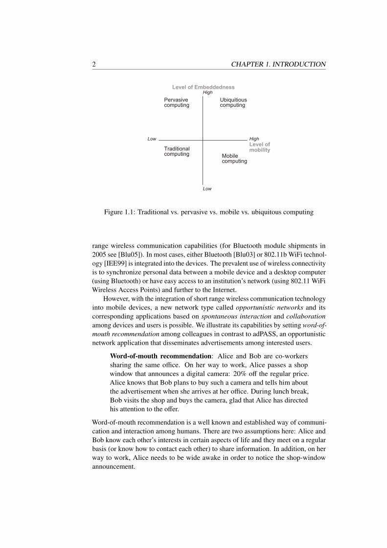


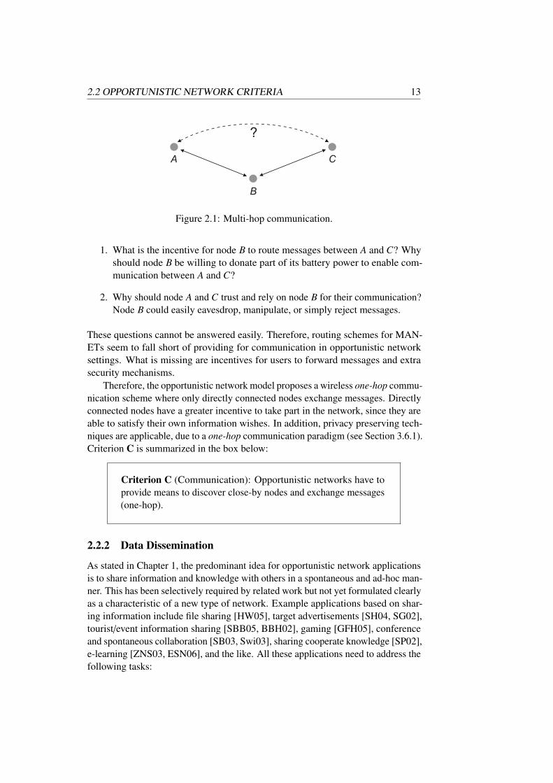


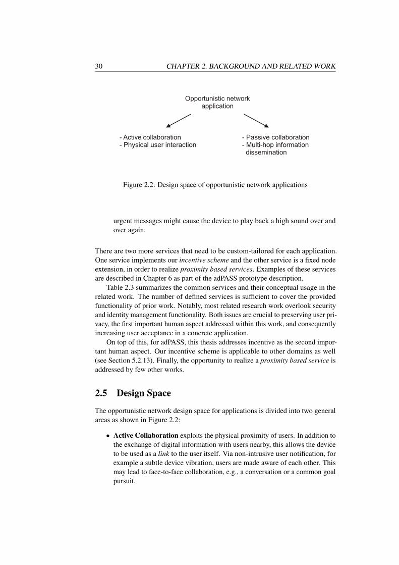

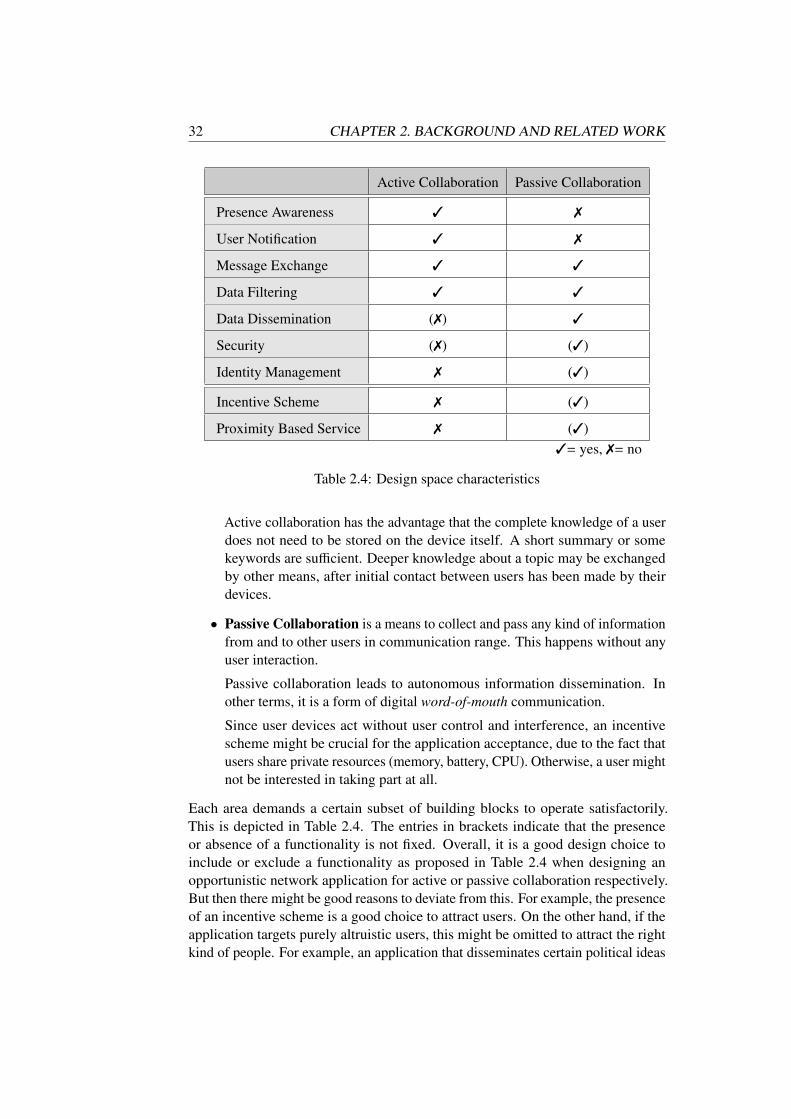


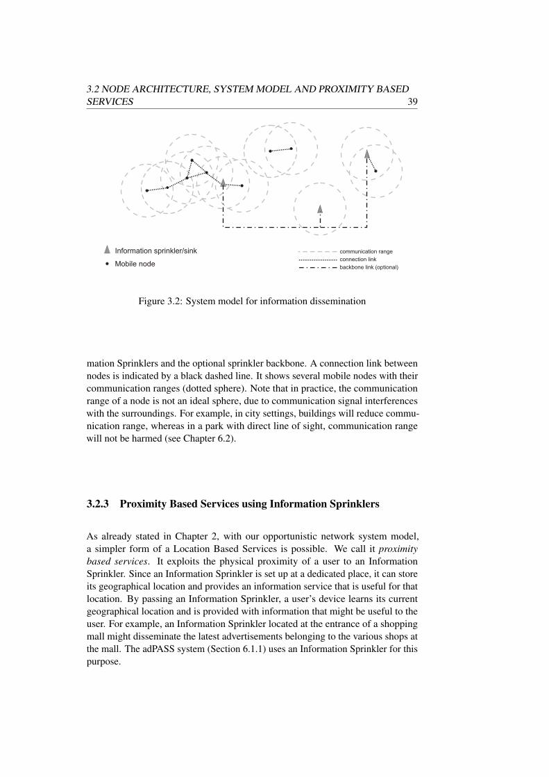

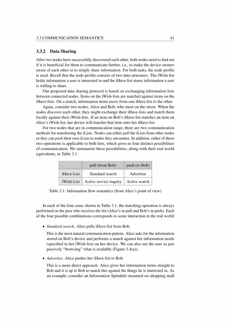
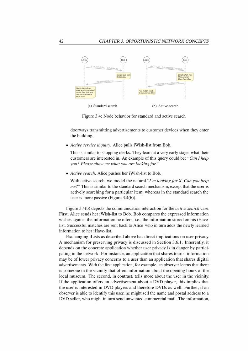


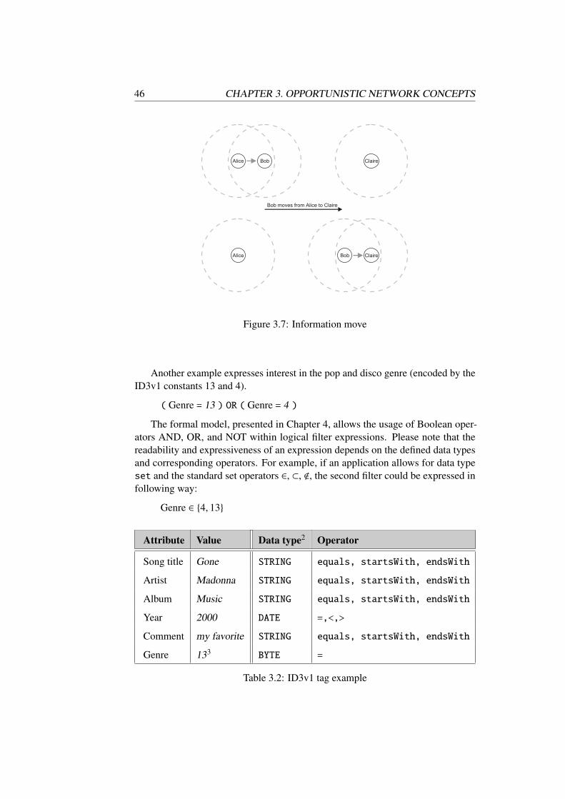


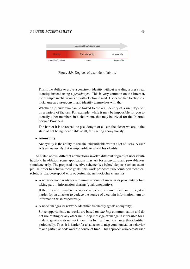


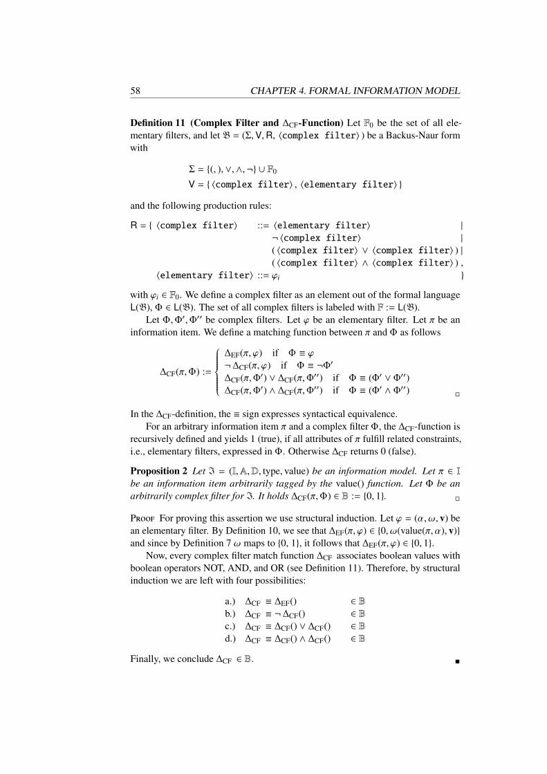

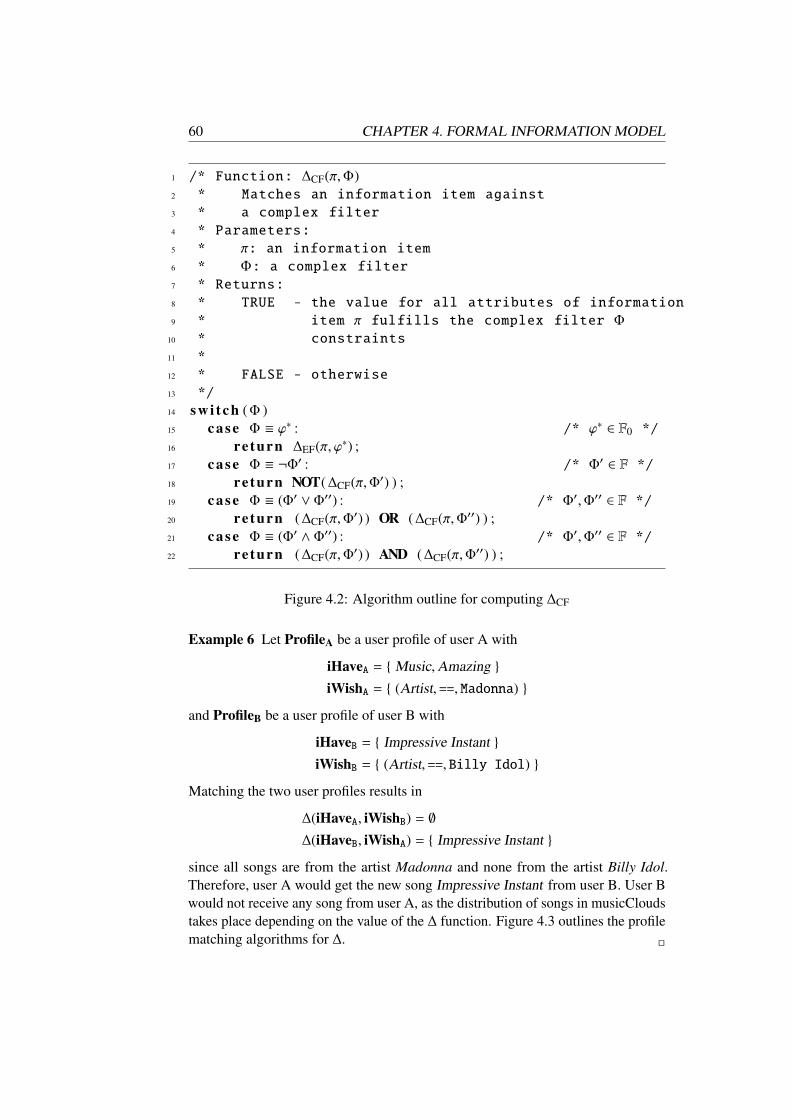


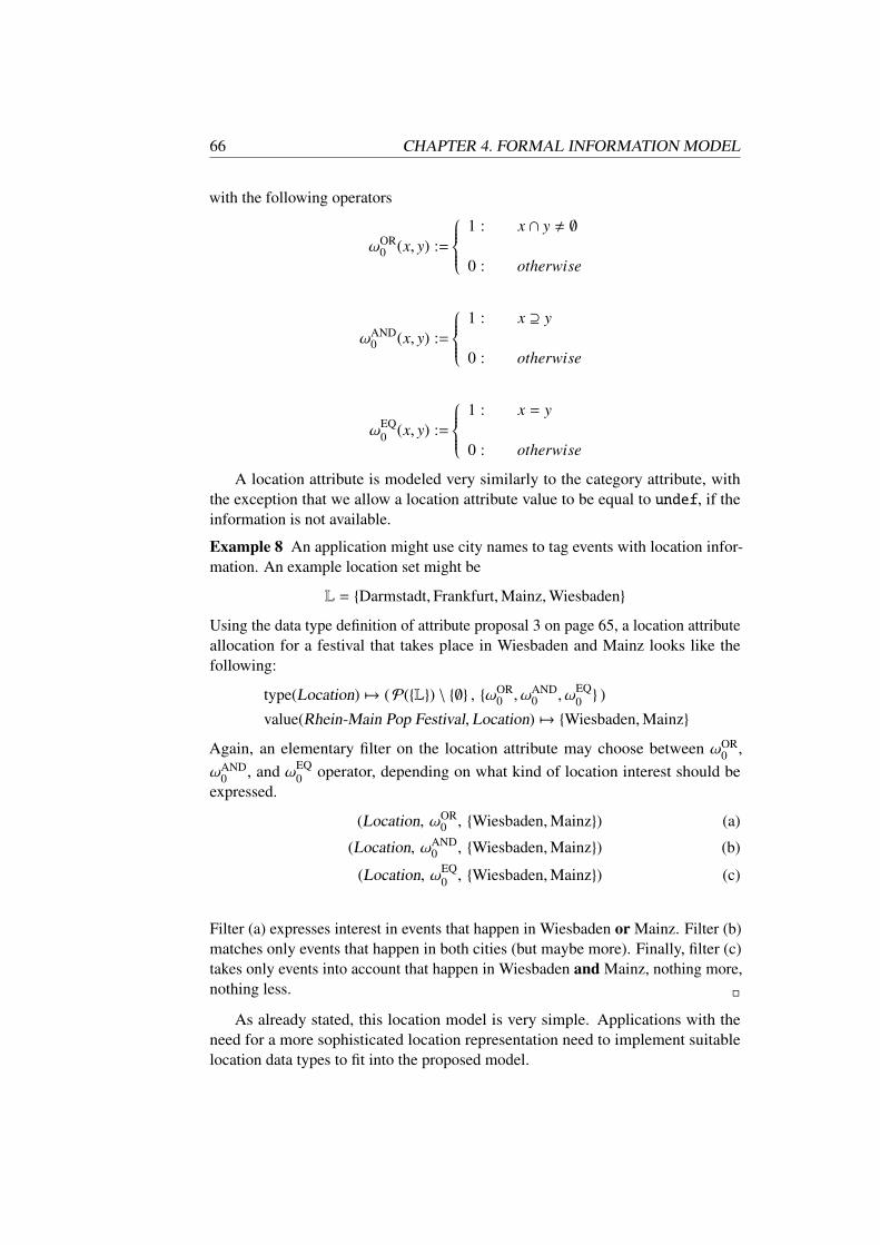
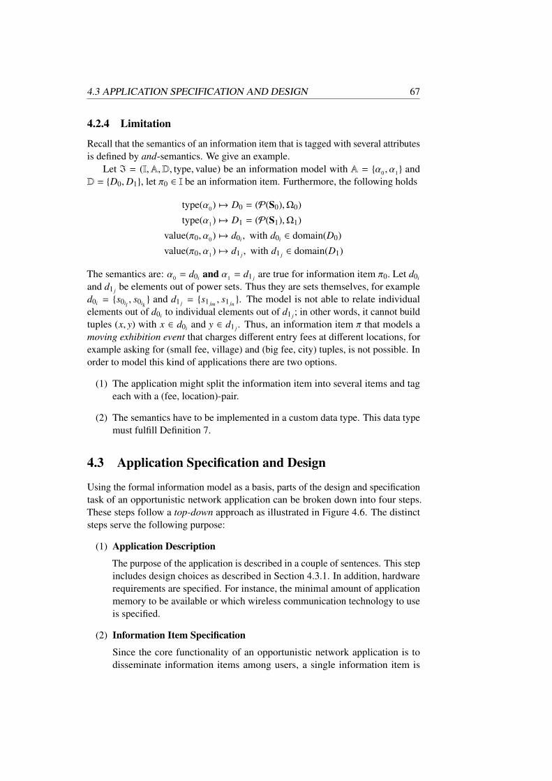


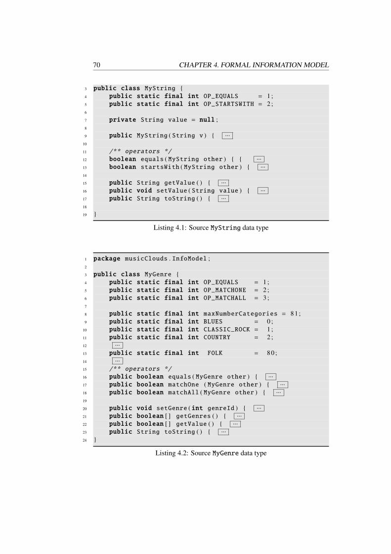


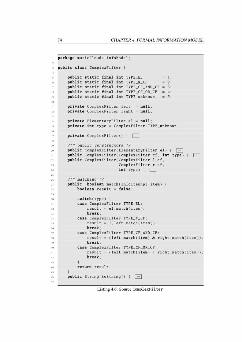


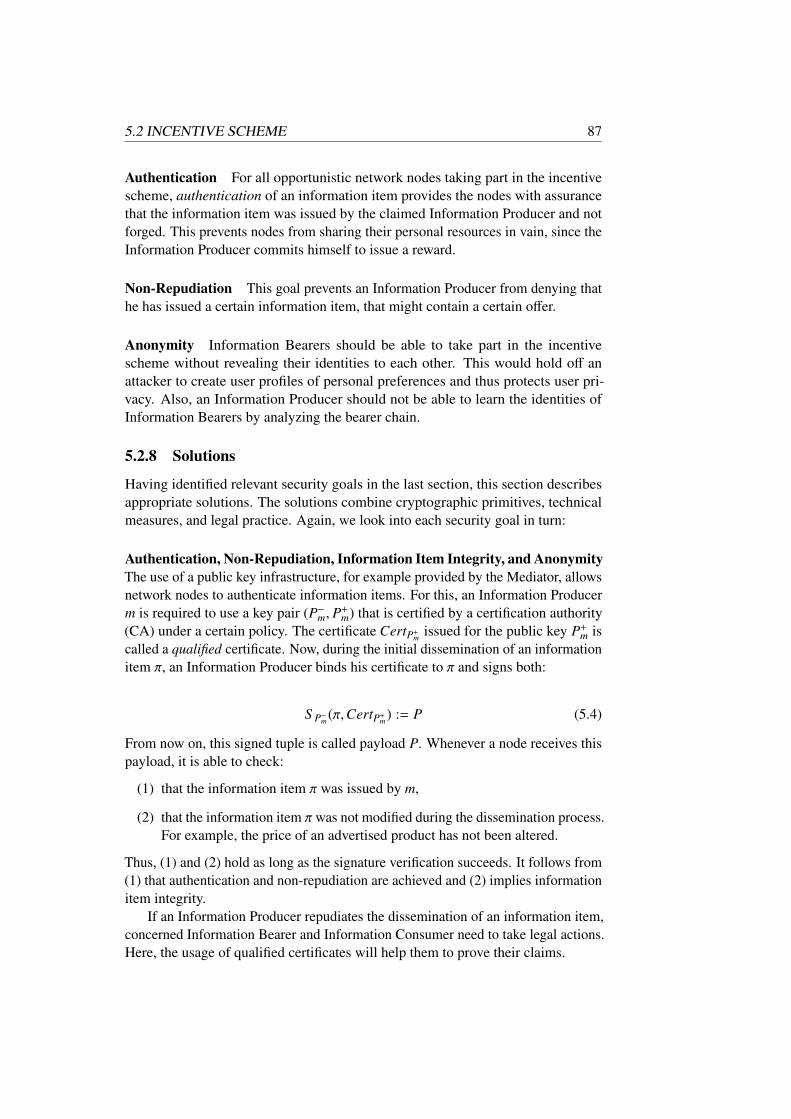
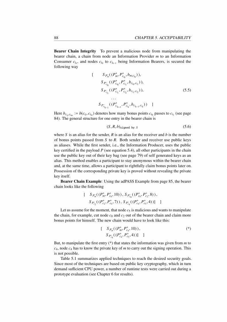

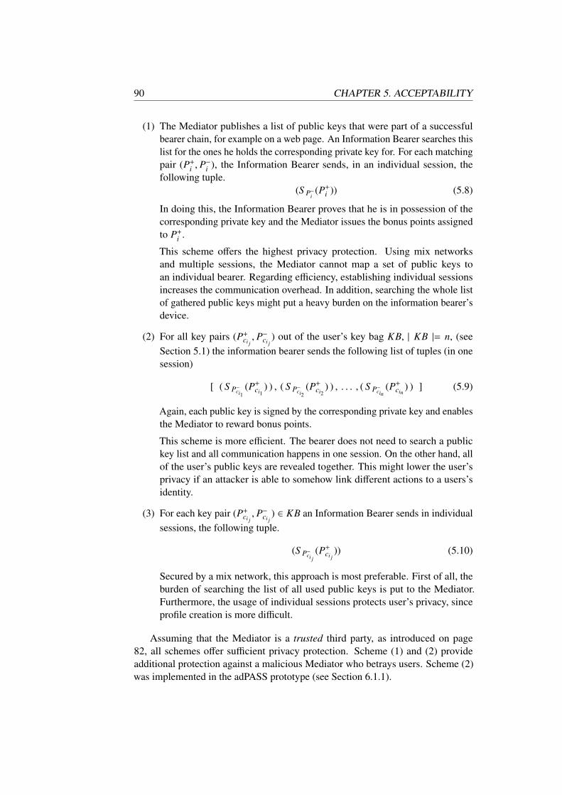
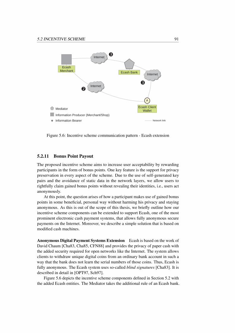


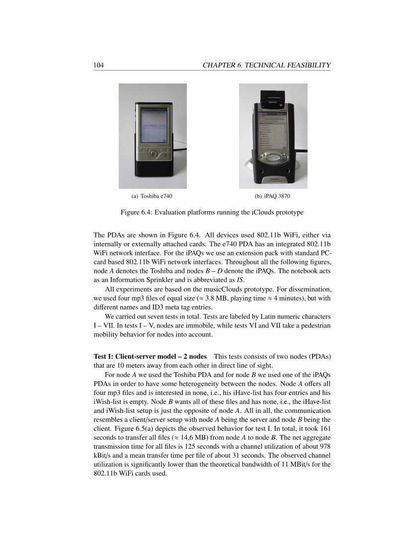
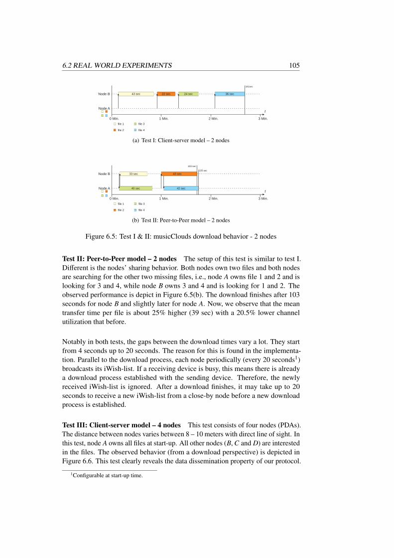
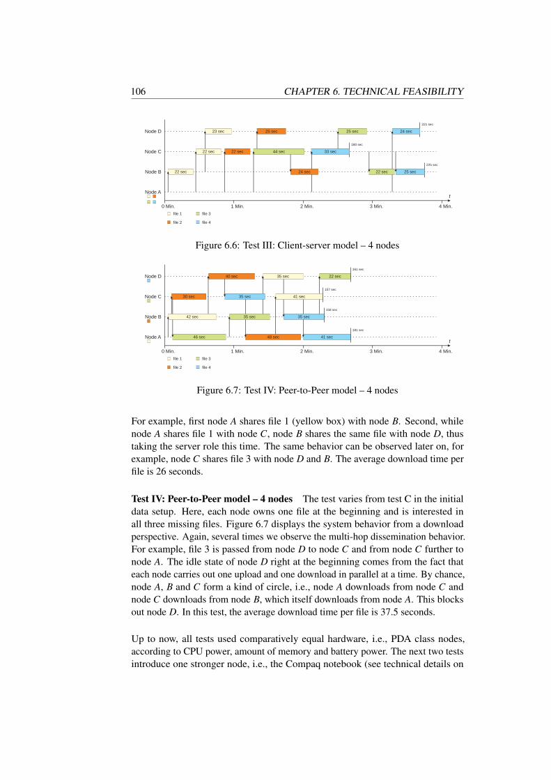

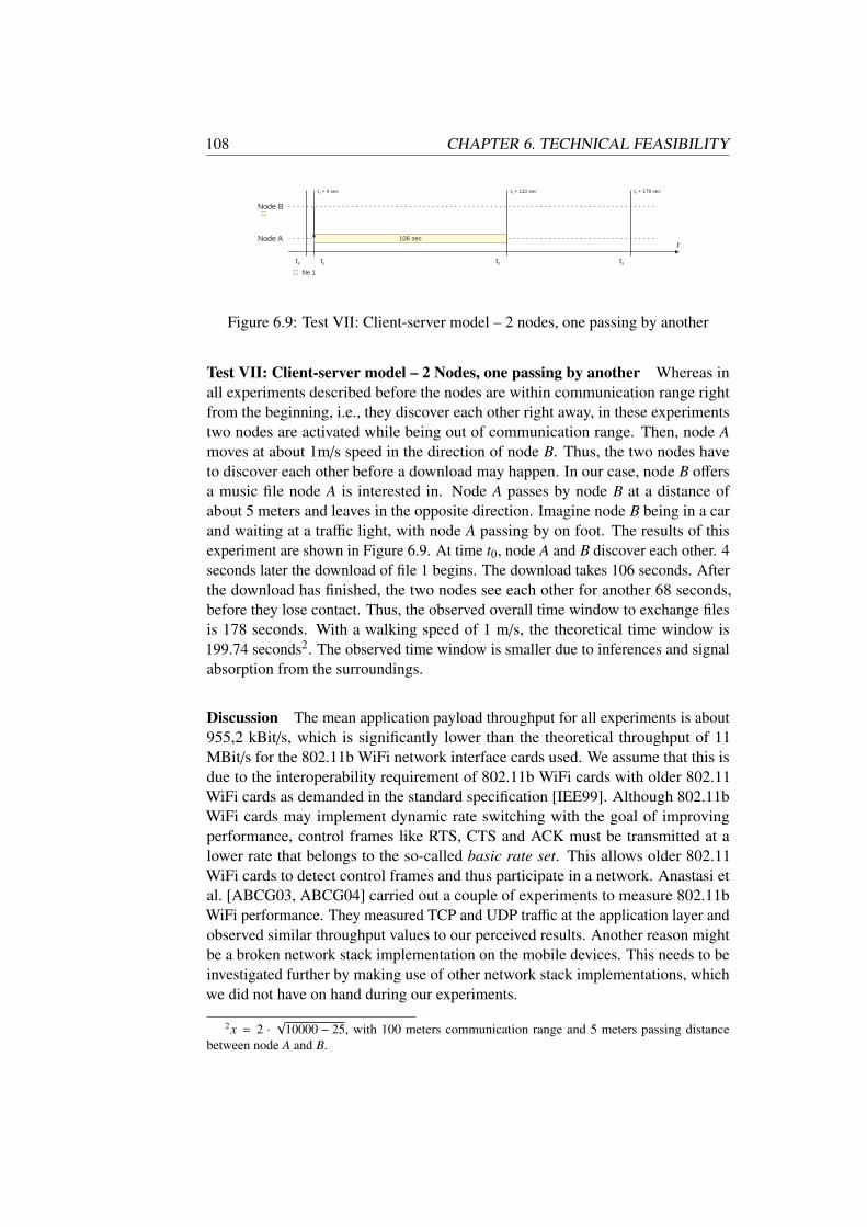


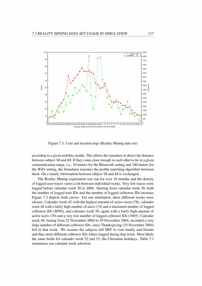
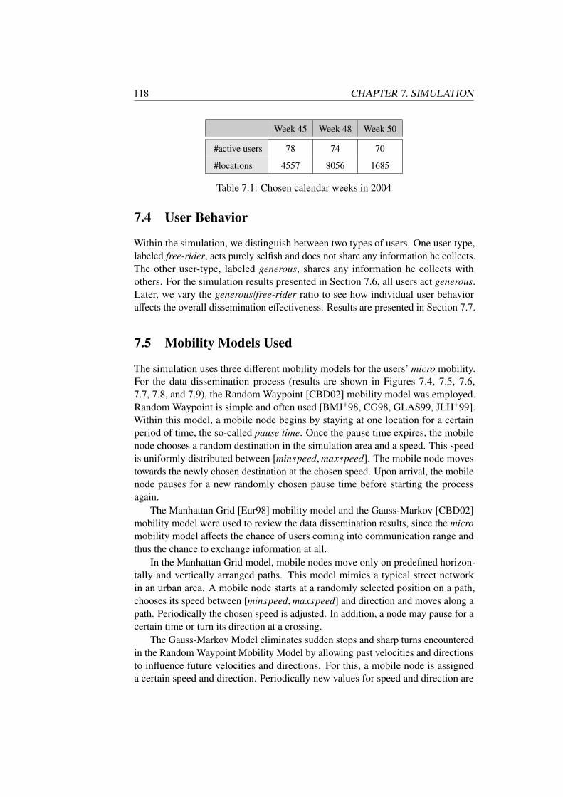

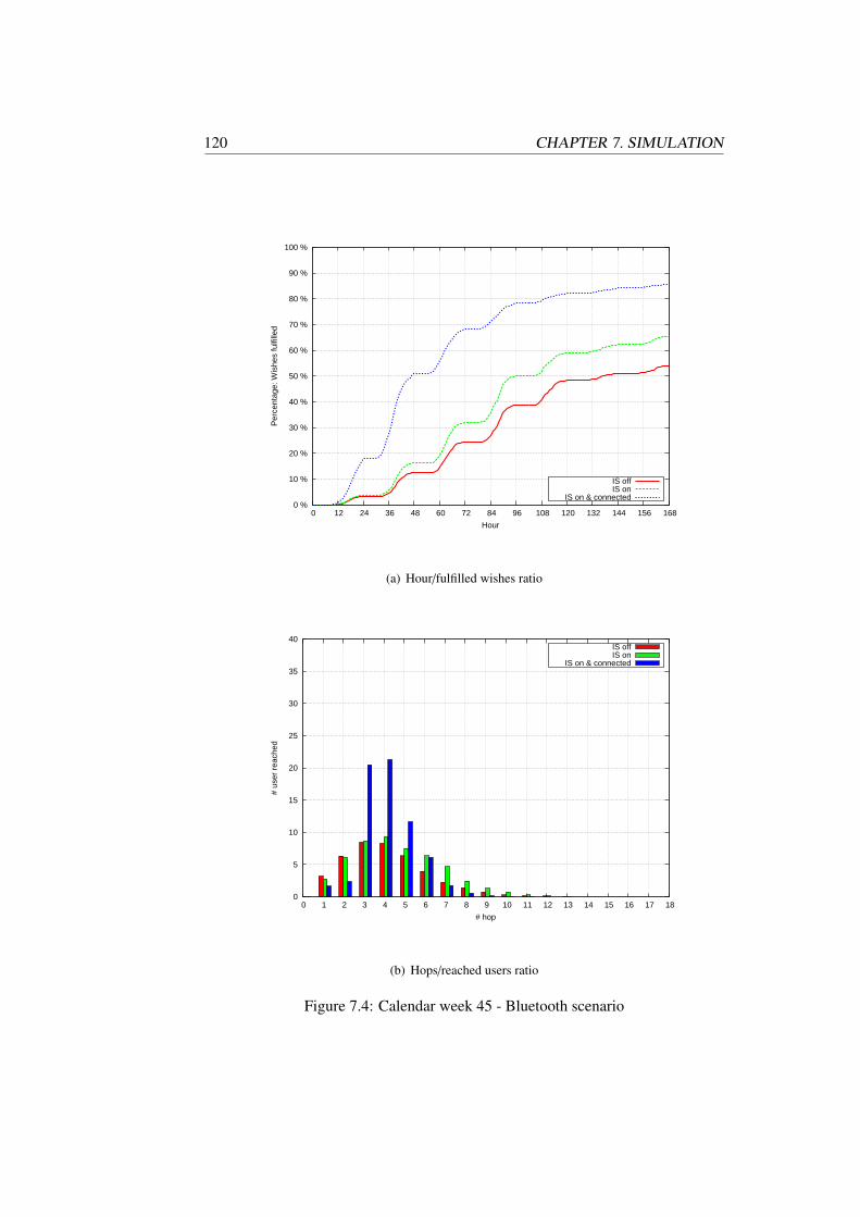

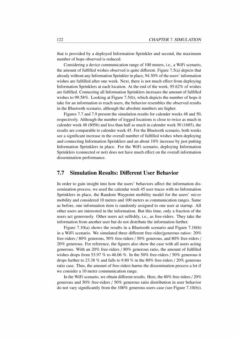
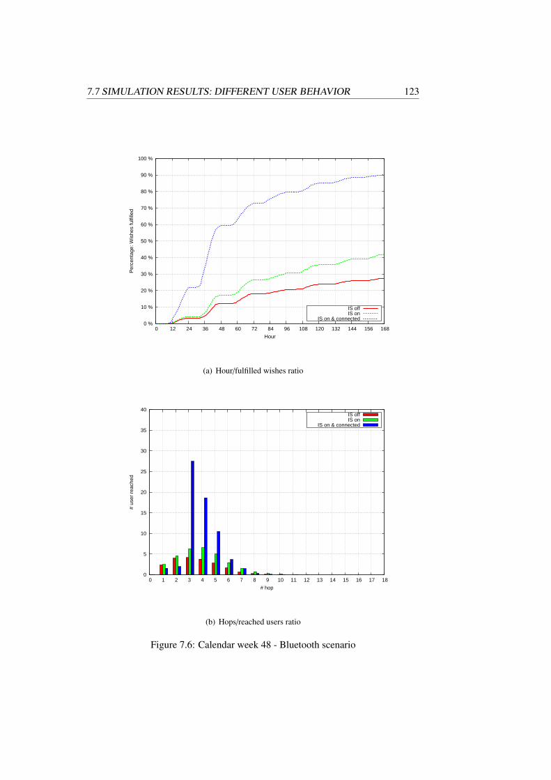
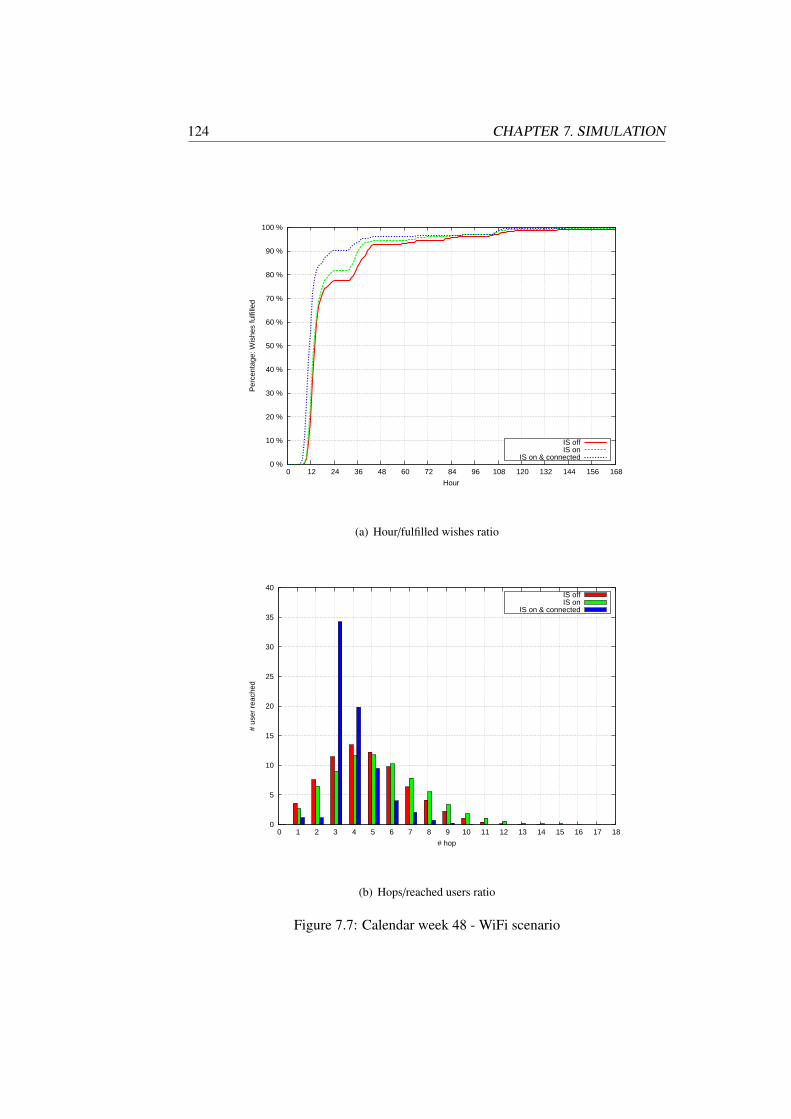


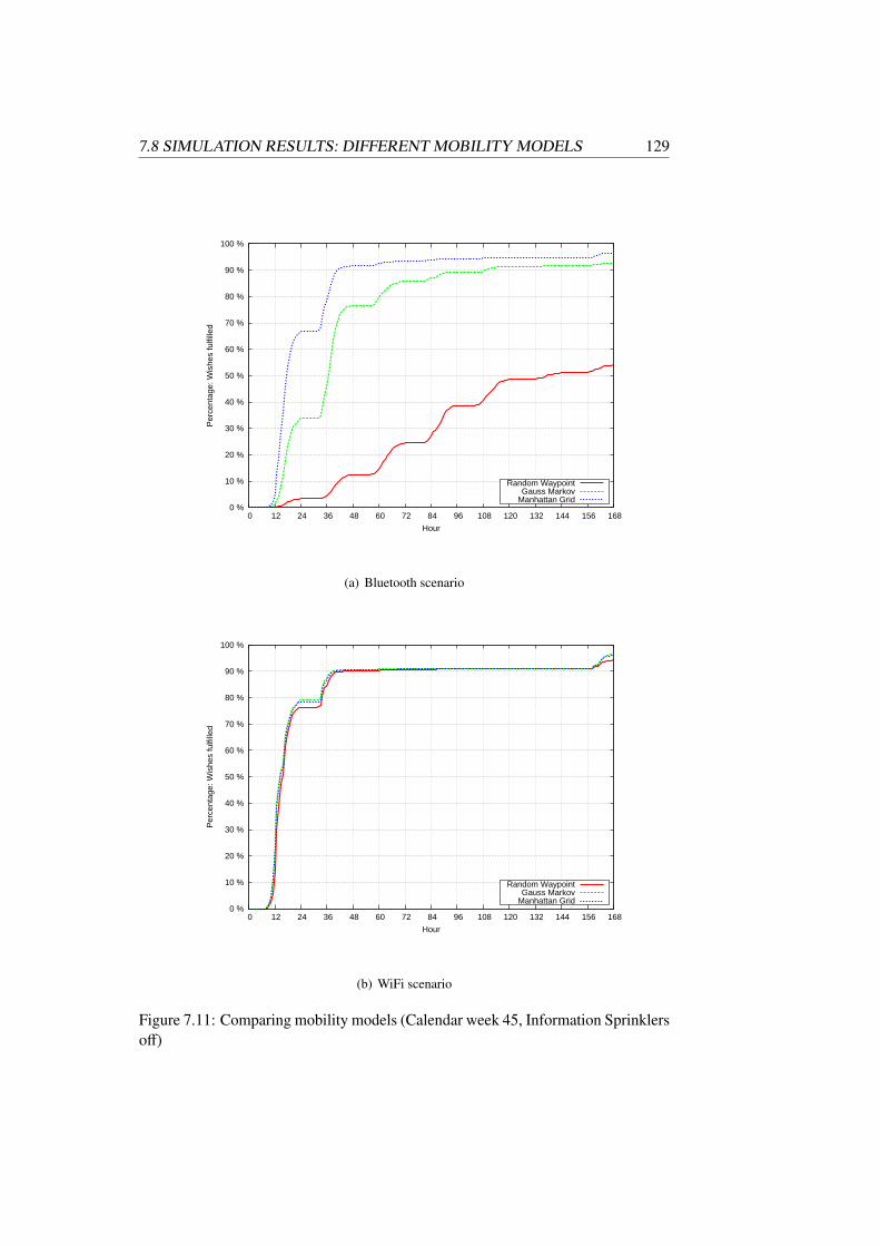


![Visualizing Community Detection in Opportunistic Networksrealitycommons.media.mit.edu/pdfs/Yoneki.pdf · The Haggle project [6] introduced the Pocket Switched Network (PSN) [2], a](https://static.documents.pub/doc/80x56/5ffc44c59caff0458b484748/visualizing-community-detection-in-opportunistic-ne-the-haggle-project-6-introduced.jpg)


