410
Command Reference Guide SmartWare Release 2.00 Customer Deliverable Documentation Part Number 80-0125 English Revision 1.01, May 22, 2002
Command Reference Guide
SmartWare Release 2.00
Customer Deliverable DocumentationPart Number 80-0125 English Revision 1.01, May 22, 2002


Legal Notice 3
Command Reference Guide, Revision 1.01
LEGAL NOTICE SmartWare Command Reference Guide Copyright © 2002 Inalp Networks AG All rights reserved. No part of this publication may be reproduced without prior written permission from Inalp Networks AG.
Limitations of Use Inalp Networks AG reserves the right to make changes in specifications and other information contained in this document without prior notice. The information provided is subject to change without notice. In no event shall Inalp Networks AG or its employees and associated companies be liable for any incidental, special, indirect or consequential damages whatsoever, including but not limited to lost profits, arising out of or related to this manual or the information contained within it, even if Inalp Networks AG has been advised of, known, or should have known, the possibility of such damages.
Trademarks Inalp, the Inalp Logo, and SmartNode are registered trademarks of Inalp Networks AG. SmartWare and SmartView are trademarks of Inalp Networks AG. All other trademarks mentioned in this document are property of their respective owners.
EU Declaration of Conformity The EU Directives covered by this Declaration 89/336/EEC Electromagnetic Compatibility Directive amended by 92/31/EEC & 93/68/EEC
72/23/EEC Low Voltage Equipment Directive amended by 93/68/EEC Note: During the transition period, products may not comply with the Low Voltage Directive.
The Products covered by this Declaration The products covered by this declaration are the SmartNode 1000 and 2000 family series devices.
The Basis on which Conformity is being Declared The products identified above comply with the requirements of the above EU directives by meeting the following standards:
• Safety compliance: EN 60950 • EMC compliance: EN 55022, EN 55024 • ETSI TBR3 (BRI) • TBR4 (PRI)
The CE mark was first applied in 2000. Inalp Networks AG Meriedweg 7 CH-3172 Niederwangen
4 Table of Contents
Command Reference Guide, Revision 1.01
TABLE OF CONTENTS Legal Notice.......................................................................................................................................................... 3 Table of Contents ................................................................................................................................................ 4 About This Guide ............................................................................................................................................. 12 1 Command Line Interface ......................................................................................................................... 15
1.1 Introduction ........................................................................................................................................ 15 1.2 Modes and Mode Groups ................................................................................................................. 15
1.2.1 Modes........................................................................................................................................... 15 1.2.2 Mode Groups .............................................................................................................................. 15 1.2.3 System Prompt............................................................................................................................ 15
1.3 Navigating the CLI............................................................................................................................. 16 1.3.1 Initial Mode................................................................................................................................. 16 1.3.2 System Changes.......................................................................................................................... 16 1.3.3 Configuration.............................................................................................................................. 16 1.3.4 Changing Mode and Exit .......................................................................................................... 16
1.4 Command Editing.............................................................................................................................. 19 1.4.1 Command Help .......................................................................................................................... 19 1.4.2 Command No Form................................................................................................................... 20 1.4.3 Command Completion .............................................................................................................. 20 1.4.4 Command History...................................................................................................................... 20 1.4.5 Command Editing Shortcuts .................................................................................................... 21 1.4.6 Command Confirmation ........................................................................................................... 21
1.5 Basic User Interface Commands....................................................................................................... 21 ?, help........................................................................................................................................................... 22 exit ................................................................................................................................................................ 24
2 Operator Execution Mode........................................................................................................................ 25 2.1 Command Overview ......................................................................................................................... 25
call ................................................................................................................................................................ 26 clear .............................................................................................................................................................. 29 debug call .................................................................................................................................................... 30 jobs ............................................................................................................................................................... 31 fg................................................................................................................................................................... 33 logout ........................................................................................................................................................... 35 ping .............................................................................................................................................................. 36 show call ...................................................................................................................................................... 38 show clock................................................................................................................................................... 39 show dsp...................................................................................................................................................... 40 show framerelay......................................................................................................................................... 41 show history................................................................................................................................................ 42 show ip interface ........................................................................................................................................ 43 show ip route .............................................................................................................................................. 45 show log ...................................................................................................................................................... 47 show napt interface.................................................................................................................................... 49 show port ethernet ..................................................................................................................................... 51 show port isdn ............................................................................................................................................ 52 show port serial .......................................................................................................................................... 53 show profile call-progress-tone................................................................................................................ 54 show profile tone-set.................................................................................................................................. 56
Table of Contents 5
Command Reference Guide, Revision 1.01
show profile voip ....................................................................................................................................... 58 show rip....................................................................................................................................................... 59 show service-policy.................................................................................................................................... 61 show uptime ............................................................................................................................................... 62 show version............................................................................................................................................... 63 show version cli .......................................................................................................................................... 65 su .................................................................................................................................................................. 66 who............................................................................................................................................................... 67
3 Administrator Execution Mode .............................................................................................................. 68 3.1 Command Overview ......................................................................................................................... 68
copy.............................................................................................................................................................. 69 debug acl ..................................................................................................................................................... 71 debug all ...................................................................................................................................................... 73 debug dsp.................................................................................................................................................... 74 debug gateway h323 .................................................................................................................................. 75 debug gateway isoip.................................................................................................................................. 77 debug isdn................................................................................................................................................... 78 debug session-control ................................................................................................................................ 80 debug session-router.................................................................................................................................. 81 debug sntp client ........................................................................................................................................ 82 debug voip-data ......................................................................................................................................... 83 enable ........................................................................................................................................................... 84 end................................................................................................................................................................ 85 erase ............................................................................................................................................................. 86 reload ........................................................................................................................................................... 87 session-control close .................................................................................................................................. 88 show............................................................................................................................................................. 89 show accounts............................................................................................................................................. 91 show context cs........................................................................................................................................... 92 show crc....................................................................................................................................................... 93 show gateway h323.................................................................................................................................... 94 show gateway isoip.................................................................................................................................... 95 show isdn .................................................................................................................................................... 96 show log supervisor................................................................................................................................... 97 show profile acl .......................................................................................................................................... 99 show profile napt ..................................................................................................................................... 100 show profile service-policy ..................................................................................................................... 101 show service-policy.................................................................................................................................. 102 show session-control................................................................................................................................ 103 show snmp ................................................................................................................................................ 104 show sntp-client ....................................................................................................................................... 106
4 Configure Mode ...................................................................................................................................... 107 4.1 Command Overview ....................................................................................................................... 107
administrator ............................................................................................................................................ 108 banner ........................................................................................................................................................ 110 cli version .................................................................................................................................................. 111 clock set...................................................................................................................................................... 113 configure.................................................................................................................................................... 114 operator ..................................................................................................................................................... 116 snmp community ..................................................................................................................................... 118 snmp host security-name ........................................................................................................................ 119 snmp target security-name ..................................................................................................................... 120
6 Table of Contents
Command Reference Guide, Revision 1.01
sntp-client.................................................................................................................................................. 121 sntp-client anycast-address..................................................................................................................... 122 sntp-client gmt-offset............................................................................................................................... 123 sntp-client local-clock-offset ................................................................................................................... 124 sntp-client local-port ................................................................................................................................ 125 sntp-client operating-mode..................................................................................................................... 126 sntp-client poll-interval ........................................................................................................................... 127 sntp-client server ...................................................................................................................................... 128 system contact........................................................................................................................................... 129 system hostname ...................................................................................................................................... 130 system location ......................................................................................................................................... 131 system provider........................................................................................................................................ 132 system subscriber ..................................................................................................................................... 133 system supplier......................................................................................................................................... 134 webserver .................................................................................................................................................. 135
5 System Mode............................................................................................................................................ 136 5.1 Command Overview ....................................................................................................................... 136
bypass-mode ............................................................................................................................................. 137 clock-source............................................................................................................................................... 138 local-inband-tones.................................................................................................................................... 139 synchronize-to-isdn-time ........................................................................................................................ 140 system ........................................................................................................................................................ 141
6 IC Voice Mode ......................................................................................................................................... 142 6.1 Command Overview ....................................................................................................................... 142
ic voice ....................................................................................................................................................... 143 pcm............................................................................................................................................................. 144
7 Profile ACL Mode ................................................................................................................................... 145 7.1 Command Overview ....................................................................................................................... 145
{ permit | deny } ip................................................................................................................................... 146 { permit | deny } icmp ............................................................................................................................. 148 { permit | deny } { tcp | udp | sctp } ...................................................................................................... 151 profile acl ................................................................................................................................................... 153
8 Profile Service-Policy Mode.................................................................................................................. 155 8.1 Command Overview ....................................................................................................................... 155 8.2 Cross Reference to Source Mode Chapter..................................................................................... 155
mode .......................................................................................................................................................... 156 profile service-policy ............................................................................................................................... 158 rate-limit .................................................................................................................................................... 160
9 Source Mode............................................................................................................................................. 161 9.1 Command Overview ....................................................................................................................... 161
debug queue statistics.............................................................................................................................. 162 police burst-size........................................................................................................................................ 164 priority ....................................................................................................................................................... 166 queue-limit ................................................................................................................................................ 168 random-detect........................................................................................................................................... 170 rate.............................................................................................................................................................. 172 set ip dscp.................................................................................................................................................. 173 set ip precedence ...................................................................................................................................... 174 set ip tos..................................................................................................................................................... 175 set layer2 cos ............................................................................................................................................. 176
Table of Contents 7
Command Reference Guide, Revision 1.01
share ........................................................................................................................................................... 177 source ......................................................................................................................................................... 179
10 Profile NAPT Mode ............................................................................................................................ 181 10.1 Command Overview ....................................................................................................................... 181
icmp default .............................................................................................................................................. 182 profile napt................................................................................................................................................ 183 static ........................................................................................................................................................... 185
11 Profile Call-Progress-Tone Mode..................................................................................................... 187 11.1 Command Overview ....................................................................................................................... 187
high-frequency.......................................................................................................................................... 188 high-frequency-level................................................................................................................................ 189 low-frequency........................................................................................................................................... 190 low-frequency-level ................................................................................................................................. 191 off1.............................................................................................................................................................. 192 off2.............................................................................................................................................................. 193 on1 .............................................................................................................................................................. 194 on2 .............................................................................................................................................................. 195 profile call-progress-tone ........................................................................................................................ 196
12 Profile Tone-Set Mode ....................................................................................................................... 197 12.1 Command Overview ....................................................................................................................... 197
map............................................................................................................................................................. 198 profile tone-set .......................................................................................................................................... 199
13 Profile VoIP Mode .............................................................................................................................. 200 13.1 Command Overview ....................................................................................................................... 200
dejitter-grow-attenuation ........................................................................................................................ 201 dejitter-grow-step..................................................................................................................................... 202 dejitter-max-delay .................................................................................................................................... 203 dejitter-max-packet-loss .......................................................................................................................... 204 dejitter-mode............................................................................................................................................. 205 dejitter-shrink-speed................................................................................................................................ 206 dtmf-relay.................................................................................................................................................. 207 echo-canceller............................................................................................................................................ 208 high-pass-filter.......................................................................................................................................... 209 post-filter ................................................................................................................................................... 210 profile voip................................................................................................................................................ 211 silence-compression ................................................................................................................................. 212
14 Context IP Mode.................................................................................................................................. 213 14.1 Command Overview ....................................................................................................................... 213
context ip ................................................................................................................................................... 214 multicast-send default-interface............................................................................................................. 215 route ........................................................................................................................................................... 216
15 Interface Mode..................................................................................................................................... 218 15.1 Command Overview ....................................................................................................................... 218
cos............................................................................................................................................................... 219 icmp redirect accept ................................................................................................................................. 220 icmp redirect send.................................................................................................................................... 221 icmp router-discovery ............................................................................................................................. 222 interface ..................................................................................................................................................... 223 ipaddress ................................................................................................................................................... 225 mtu ............................................................................................................................................................. 227
8 Table of Contents
Command Reference Guide, Revision 1.01
point-to-point............................................................................................................................................ 228 rip announce ............................................................................................................................................. 229 rip announce host..................................................................................................................................... 231 rip announce static ................................................................................................................................... 233 rip auto-summary .................................................................................................................................... 235 rip default-route-value ............................................................................................................................ 237 rip learn default ........................................................................................................................................ 239 rip learn host ............................................................................................................................................. 241 rip listen..................................................................................................................................................... 243 rip poison-reverse .................................................................................................................................... 245 rip receive version.................................................................................................................................... 247 rip route-holddown ................................................................................................................................. 249 rip send version ........................................................................................................................................ 251 rip split-horizon........................................................................................................................................ 253 rip supply .................................................................................................................................................. 255 use profile acl ............................................................................................................................................ 257 use profile napt......................................................................................................................................... 259 use profile service-policy ........................................................................................................................ 260
16 Context CS Mode................................................................................................................................. 261 16.1 Command Overview ....................................................................................................................... 261
bearer-capability....................................................................................................................................... 262 called-party ............................................................................................................................................... 264 calling-party .............................................................................................................................................. 266 complex-function...................................................................................................................................... 268 context cs ................................................................................................................................................... 269 date............................................................................................................................................................. 270 delete.......................................................................................................................................................... 272 number-manipulation ............................................................................................................................. 273 number-prefix........................................................................................................................................... 275 shutdown................................................................................................................................................... 276 time............................................................................................................................................................. 278 translation-table........................................................................................................................................ 280 use tone-set-profile................................................................................................................................... 281 weekday..................................................................................................................................................... 282
17 Interface PSTN Mode ......................................................................................................................... 284 17.1 Command Overview ....................................................................................................................... 284
bind port .................................................................................................................................................... 285 digit-collection .......................................................................................................................................... 286 fallback....................................................................................................................................................... 288 interface pstn............................................................................................................................................. 289 routing ....................................................................................................................................................... 290 use tone-set-profile................................................................................................................................... 291
18 Interface H.323 Mode.......................................................................................................................... 292 18.1 Command Overview ....................................................................................................................... 292
bind gateway............................................................................................................................................. 293 codec .......................................................................................................................................................... 294 dejitter-grow-attenuation ........................................................................................................................ 295 dejitter-grow-step..................................................................................................................................... 296 dejitter-max-delay .................................................................................................................................... 297 dejitter-max-packet-loss .......................................................................................................................... 298 dejitter-mode............................................................................................................................................. 299
Table of Contents 9
Command Reference Guide, Revision 1.01
dejitter-shrink-speed................................................................................................................................ 300 digit-collection .......................................................................................................................................... 301 dtmf-relay.................................................................................................................................................. 303 echo-canceller............................................................................................................................................ 304 fallback....................................................................................................................................................... 305 interface h323 ............................................................................................................................................ 306 portaddress ............................................................................................................................................... 307 remoteip..................................................................................................................................................... 308 routing ....................................................................................................................................................... 309 silence-compression ................................................................................................................................. 310 use tone-set-profile................................................................................................................................... 311 voice-volume............................................................................................................................................. 312
19 Interface ISoIP Mode.......................................................................................................................... 313 19.1 Command Overview ....................................................................................................................... 313
bind gateway isoip ................................................................................................................................... 314 codec .......................................................................................................................................................... 315 dejitter-grow-attenuation ........................................................................................................................ 317 dejitter-grow-step..................................................................................................................................... 318 dejitter-max-delay .................................................................................................................................... 319 dejitter-max-packet-loss .......................................................................................................................... 320 dejitter-mode............................................................................................................................................. 321 dejitter-shrink-speed................................................................................................................................ 322 digit-collection .......................................................................................................................................... 323 dtmf-relay.................................................................................................................................................. 325 echo-canceller............................................................................................................................................ 326 fallback....................................................................................................................................................... 327 interface isoip............................................................................................................................................ 328 portaddress ............................................................................................................................................... 329 remoteip..................................................................................................................................................... 330 routing ....................................................................................................................................................... 331 silence-compression ................................................................................................................................. 332 use tone-set-profile................................................................................................................................... 333 voice-volume............................................................................................................................................. 334
20 Gateway H.323 Mode.......................................................................................................................... 335 20.1 Command Overview ....................................................................................................................... 335
codec .......................................................................................................................................................... 336 early-h245 .................................................................................................................................................. 338 faststart ...................................................................................................................................................... 339 gatekeeper-discovery............................................................................................................................... 340 gateway h323 ............................................................................................................................................ 342 q931-tunneling.......................................................................................................................................... 343 ras ............................................................................................................................................................... 344 shutdown................................................................................................................................................... 345 use voip-profile......................................................................................................................................... 346 alias............................................................................................................................................................. 347 bind interface ............................................................................................................................................ 348 call-signaling-port .................................................................................................................................... 349
21 Gateway ISoIP Mode.......................................................................................................................... 350 21.1 Command Overview ....................................................................................................................... 350
codec .......................................................................................................................................................... 351 gateway isoip ............................................................................................................................................ 353
10 Table of Contents
Command Reference Guide, Revision 1.01
shutdown................................................................................................................................................... 354 use voip-profile......................................................................................................................................... 355
22 Port Ethernet Mode ............................................................................................................................. 356 22.1 Command Overview ....................................................................................................................... 356
bind interface ............................................................................................................................................ 357 cos............................................................................................................................................................... 359 encapsulation ............................................................................................................................................ 361 frame-format ............................................................................................................................................. 362 medium...................................................................................................................................................... 363 port ethernet.............................................................................................................................................. 364 shutdown................................................................................................................................................... 365 vlan............................................................................................................................................................. 366
23 Port Serial Mode.................................................................................................................................. 367 23.1 Command Overview ....................................................................................................................... 367
encapsulation ............................................................................................................................................ 368 hardware-port........................................................................................................................................... 369 port serial................................................................................................................................................... 370 shutdown................................................................................................................................................... 371 transmit-data-on-edge ............................................................................................................................. 372
24 Frame Relay Mode .............................................................................................................................. 373 24.1 Command Overview ....................................................................................................................... 373
framerelay ................................................................................................................................................. 374 keepalive.................................................................................................................................................... 375 lmi-type...................................................................................................................................................... 376
25 PVC Mode............................................................................................................................................. 377 25.1 Command Overview ....................................................................................................................... 377
bind interface ............................................................................................................................................ 378 encapsulation ............................................................................................................................................ 380 pvc .............................................................................................................................................................. 381 shutdown................................................................................................................................................... 383
26 Port ISDN Mode.................................................................................................................................. 384 26.1 Command Overview ....................................................................................................................... 384
channel-hunting ....................................................................................................................................... 385 channel-numbering.................................................................................................................................. 386 channel-range ........................................................................................................................................... 387 clock-mode ................................................................................................................................................ 388 down .......................................................................................................................................................... 389 l2proto........................................................................................................................................................ 390 l3proto........................................................................................................................................................ 391 loop............................................................................................................................................................. 392 max-channels ............................................................................................................................................ 393 port isdn .................................................................................................................................................... 394 smart-disconnect ...................................................................................................................................... 395 uni-side ...................................................................................................................................................... 396 up................................................................................................................................................................ 397
Appendix A ...................................................................................................................................................... 398 Appendix B....................................................................................................................................................... 400 Appendix C ...................................................................................................................................................... 405

Table of Contents 11
Command Reference Guide, Revision 1.01
Index .................................................................................................................................................................. 407
12 About this Guide
ABOUT THIS GUIDE Objective The objective of this SmartWare Command Reference Guide is to provide information concerning the syntax and usage of the command set. The aim is to enable you to be able to consult a more detailed command description than is given in the Software Configuration Guide. For hardware configuration information refer to the SmartNode Hardware Installation Guide.
Intended Audience The guide is intended primarily for the following audiences:
• Technical staff who are familiar with electronic circuitry, networking theory and have experience as an electronic or electromechanical technician.
• System administrators with a basic networking background and experience, but who might not be familiar with the SmartNode.
• System administrators who are responsible for installing and configuring networking equipment and who are familiar with the SmartNode.
Document Conventions Inalp documentation uses the conventions listed in Table i below to convey information.
Notice Description
Note Helpful suggestion or important information and instructions
Warning Situation that could cause bodily injury, or equipment damage or data loss
Caution Situation that could put equipment or data at risk
Table i: Notice Conventions
Document Organization This document consists of following chapters:
• Command Line Interface • Operator Execution Mode • Administrator Execution Mode • Configure Mode • System Mode • IC Voice Mode • Profile ACL Mode • Profile Service-Policy Mode • Source Mode • Profile NAPT Mode • Profile Call-Progress-Tone Mode • Profile Tone-Set Mode • Profile VoIP Mode • Context IP Mode • Interface Mode • Context CS Mode
About this Guide 13
Command Reference Guide, Revision 1.01
• Interface PSTN Mode • Interface H.323 Mode • Interface ISoIP Mode • Gateway H.323 Mode • Gateway ISoIP Mode • Port Ethernet Mode • Port Serial Mode • Frame Relay Mode • PVC Mode • Port ISDN Mode
In addition three appendixes and an index are to be found at the end of the document.
Typographical Conventions Throughout this guide, we use certain typographical conventions to distinguish elements of commands and examples. In general, the conventions we use conform to those found in IEEE POSIX publications. The following sections summarize our conventions for command and example descriptions.
Command Description Command descriptions use the following conventions:
• Commands and keywords are indicated in boldface style. • Arguments where the user supplies the value are indicated in italics style and are surrounded
by <angle brackets>. • Optional arguments within commands are shown in square brackets ([ ]), alternative
parameters within commands are separated by vertical bars ( | ). • Alternative but required parameters are shown within grouped braces ({ }) and are separated
by vertical bars ( | ).
Example Description Examples use the following conventions:
• The style Terminal is used for example descriptions. • System prompts are of the form SN(mode)# for interactive sessions. Here SN is the currently
configured nodename of the device, and mode is a string indicating the current configuration mode, if applicable. For example, the prompt in interface mode, assuming an IP interface named lan, is SN(if-ip)[lan]#.
• Information displayed by the system is in Terminal style. • Information that you should enter is in boldface Terminal style.
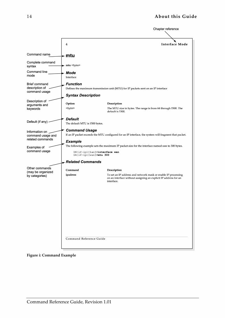
Figure i shows the various fields in a command description.
14 About this Guide
Command Reference Guide, Revision 1.01
Figure i: Command Example
Command Line Interface 15
1 COMMAND LINE INTERFACE 1.1 Introduction The user interface to the SmartWare is called the Command Line Interface (CLI). You can access the CLI either from the console port or through a Telnet session. You can perform all configuration tasks and monitor the SmartWare configuration by the input of commands at the CLI. All CLI commands are simple strings of keywords and user-specified arguments. This chapter gives an overview of the user interface and the basic features that allow you to navigate the CLI effectively. The following topics are covered:
• Modes and Mode Groups • Navigating the CLI • Command Editing • Syntax Description
1.2 Modes and Mode Groups
1.2.1 Modes The CLI commands are grouped into modes, which are organized hierarchically. A command mode is an environment within which a group of related commands is valid. All commands are mode-specific, and certain commands are valid in more than one mode. A command mode provides command line completion and context help for the commands within that mode.
1.2.2 Mode Groups The various modes are organized into mode groups. There are two mode groups:
• The executive mode group, which contains the modes operator excution and administrator execution. Note that ‘execution’ is often shortened to ‘exec’ in the text
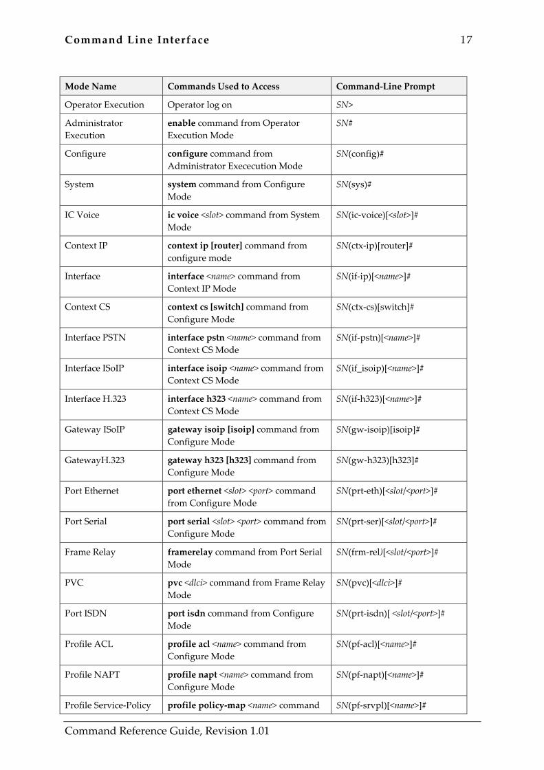
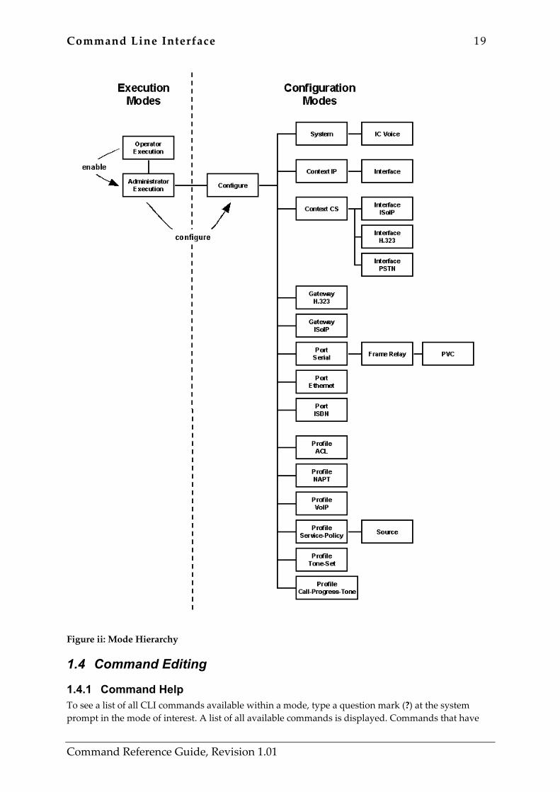
• the configuration mode group, which contains all of the remaining modes. Figure ii shows the hierarchy of modes and mode groups. An overview of the modes, the commands used to enter them and the resulting changes in the CLI prompt is given in Table 1-1. The operator’s current working mode is indicated by the CLI prompt, as described in Chapter 1.2.3, “System Prompt”.
1.2.3 System Prompt In operator execution mode the system prompt is of the form:
SN> In the privileged administrator execution mode:
SN# In the privileged configuration modes:
16 Command Line Interface
Command Reference Guide, Revision 1.01
SN(mode)#
Where:
• SN is the currently configured name of the node, or the IP address of the node or the hardware type of the device that is being configured, and
• mode is a string indicating the current configuration mode as applicable. Example: The prompt in Port ISDN Mode while configuring the ISDN interface at slot 0 port 0 is shown below.
SN(prt-isdn)[0/0]#
1.3 Navigating the CLI
1.3.1 Initial Mode Upon login, the CLI is always in the operator execution mode that is nonprivileged execution, by default. This mode allows the operator to examine the state of the system through a subset of the available CLI commands, but not to configure the system.
1.3.2 System Changes In order to make configuration changes to the system, administrator execution (privileged execution) modes must be entered. The enable command is used for this purpose. Once in administrator execution mode, all of the system commands are available to the privileged user.
1.3.3 Configuration To make configuration changes the configuration modes must be entered using the configure command. From here the other configuration modes are accessible as diagrammed in the overview in Figure ii.
1.3.4 Changing Mode and Exit Within any configuration mode, the exit command brings the user up one level in the mode hierarchy. For example, when in isdn port configuration mode, typing exit will take you to configuration mode. The exit command also terminates a CLI session when typed from the operator execution mode. The end command causes the CLI to immediately exit any configuration mode and return to the administrator execution mode. A session can also be terminated using the quit command within any mode. To end a session the logout command can be used.
Command Line Interface 17
Command Reference Guide, Revision 1.01
Mode Name Commands Used to Access Command-Line Prompt
Operator Execution Operator log on SN>
Administrator Execution
enable command from Operator Execution Mode
SN#
Configure configure command from Administrator Exececution Mode
SN(config)#
System system command from Configure Mode
SN(sys)#
IC Voice ic voice <slot> command from System Mode
SN(ic-voice)[<slot>]#
Context IP context ip [router] command from configure mode
SN(ctx-ip)[router]#
Interface interface <name> command from Context IP Mode
SN(if-ip)[<name>]#
Context CS context cs [switch] command from Configure Mode
SN(ctx-cs)[switch]#
Interface PSTN interface pstn <name> command from Context CS Mode
SN(if-pstn)[<name>]#
Interface ISoIP interface isoip <name> command from Context CS Mode
SN(if_isoip)[<name>]#
Interface H.323 interface h323 <name> command from Context CS Mode
SN(if-h323)[<name>]#
Gateway ISoIP gateway isoip [isoip] command from Configure Mode
SN(gw-isoip)[isoip]#
GatewayH.323 gateway h323 [h323] command from Configure Mode
SN(gw-h323)[h323]#
Port Ethernet port ethernet <slot> <port> command from Configure Mode
SN(prt-eth)[<slot/<port>]#
Port Serial port serial <slot> <port> command from Configure Mode
SN(prt-ser)[<slot/<port>]#
Frame Relay framerelay command from Port Serial Mode
SN(frm-rel)[<slot/<port>]#
PVC pvc <dlci> command from Frame Relay Mode
SN(pvc)[<dlci>]#
Port ISDN port isdn command from Configure Mode
SN(prt-isdn)[ <slot/<port>]#
Profile ACL profile acl <name> command from Configure Mode
SN(pf-acl)[<name>]#
Profile NAPT profile napt <name> command from Configure Mode
SN(pf-napt)[<name>]#
Profile Service-Policy profile policy-map <name> command SN(pf-srvpl)[<name>]#
18 Command Line Interface
Command Reference Guide, Revision 1.01
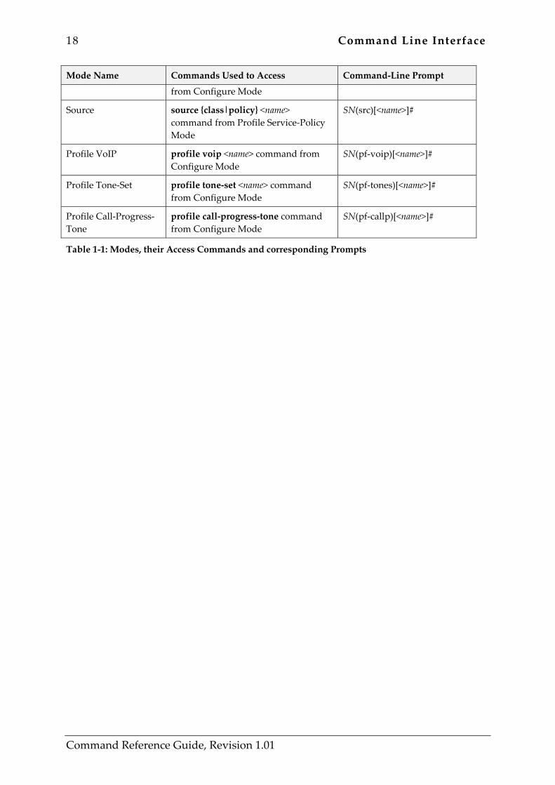
Mode Name Commands Used to Access Command-Line Prompt
from Configure Mode
Source source {class|policy} <name> command from Profile Service-Policy Mode
SN(src)[<name>]#
Profile VoIP profile voip <name> command from Configure Mode
SN(pf-voip)[<name>]#
Profile Tone-Set profile tone-set <name> command from Configure Mode
SN(pf-tones)[<name>]#
Profile Call-Progress-Tone
profile call-progress-tone command from Configure Mode
SN(pf-callp)[<name>]#
Table 1-1: Modes, their Access Commands and corresponding Prompts
Command Line Interface 19
Command Reference Guide, Revision 1.01
Figure ii: Mode Hierarchy
1.4 Command Editing
1.4.1 Command Help To see a list of all CLI commands available within a mode, type a question mark (?) at the system prompt in the mode of interest. A list of all available commands is displayed. Commands that have
20 Command Line Interface
Command Reference Guide, Revision 1.01
become available in the current mode are displayed at the bottom of the list, separated by a line. Commands from higher hierarchy levels are listed at the top. You can also type the question mark while in the middle of entering a command. Doing so displays the list of allowed choices for the next keyword in the command. Liberal use of the question mark function is an easy and effective way to explore the command syntax.
1.4.2 Command No Form Almost every command supports the keyword no. Typing the no keyword in front of a command disables the function or “cancels” a command’s effect from the configuration. Example: To enable send RIP on an interface, enter the command rip supply. To disable send RIP on an interface and remove the command’s effect from the configuration, enter the command no rip supply.
1.4.3 Command Completion You can use the Tab key in any mode to carry out command completion. Partially typing a command name and pressing the Tab key causes the command to be displayed in full up to the point where a further choice has to be made. In all modes, the system recognizes and accepts partially typed command keywords, provided a sufficient amount has been entered to uniquely recognize it. For example, rather than typing configure, typing conf causes the CLI to enter configuration mode. However, if you entered the string co, an error would be returned because insufficient characters have been entered to distinguish between the configure command and the copy command. Automatic pagination of output at the command line interface for console and Telnet sessions is supported. SmartWare displays -More- to indicate the presence of more output. You can use a subset of the commands available in the UNIX more command, such as pressing space to show the next page of output, typing q to quit, pressing enter to show one additional line of output, and so on.
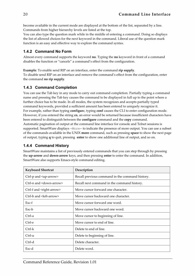
1.4.4 Command History SmartWare maintains a list of previously entered commands that you can step through by pressing the up-arrow and down-arrow keys, and then pressing enter to enter the command. In addition, SmartWare also supports Emacs-style command editing.
Keyboard Shortcut Description
Ctrl-p and <up-arrow> Recall previous command in the command history.
Ctrl-n and <down-arrow> Recall next command in the command history.
Ctrl-f and <right-arrow> Move cursor forward one character.
Ctrl-b and <left-arrow> Move cursor backward one character.
Esc-f Move cursor forward one word.
Esc-b Move cursor backward one word.
Ctrl-a Move cursor to beginning of line.
Ctrl-e Move cursor to end of line.
Ctrl-k Delete to end of line.
Ctrl-u Delete to beginning of line.
Ctrl-d Delete character.
Esc-d Delete word.
Command Line Interface 21
Command Reference Guide, Revision 1.01
Keyboard Shortcut Description
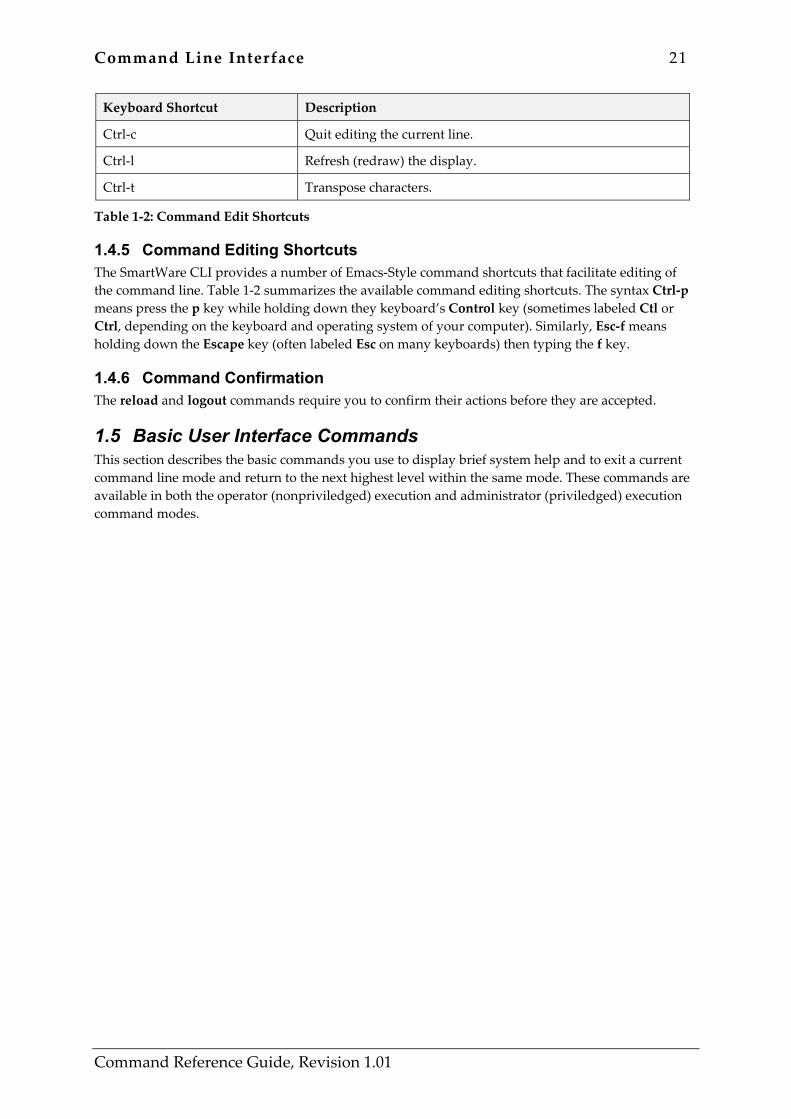
Ctrl-c Quit editing the current line.
Ctrl-l Refresh (redraw) the display.
Ctrl-t Transpose characters.
Table 1-2: Command Edit Shortcuts
1.4.5 Command Editing Shortcuts The SmartWare CLI provides a number of Emacs-Style command shortcuts that facilitate editing of the command line. Table 1-2 summarizes the available command editing shortcuts. The syntax Ctrl-p means press the p key while holding down they keyboard’s Control key (sometimes labeled Ctl or Ctrl, depending on the keyboard and operating system of your computer). Similarly, Esc-f means holding down the Escape key (often labeled Esc on many keyboards) then typing the f key.
1.4.6 Command Confirmation The reload and logout commands require you to confirm their actions before they are accepted.
1.5 Basic User Interface Commands This section describes the basic commands you use to display brief system help and to exit a current command line mode and return to the next highest level within the same mode. These commands are available in both the operator (nonpriviledged) execution and administrator (priviledged) execution command modes.
22 Command Line Interface
Command Reference Guide, Revision 1.01
?, help ? | help
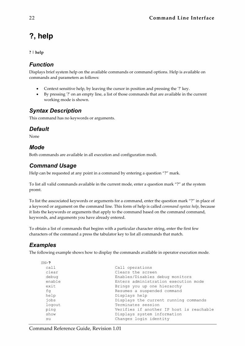
Function Displays brief system help on the available commands or command options. Help is available on commands and parameters as follows:
• Context sensitive help, by leaving the cursor in position and pressing the '?' key. • By pressing '?' on an empty line, a list of those commands that are available in the current
working mode is shown.
Syntax Description This command has no keywords or arguments.
Default None
Mode Both commands are available in all execution and configuration modi.
Command Usage Help can be requested at any point in a command by entering a question “?” mark. To list all valid commands available in the current mode, enter a question mark “?” at the system promt. To list the asscociated keywords or arguments for a command, enter the question mark “?” in place of a keyword or argument on the command line. This form of help is called command syntax help, because it lists the keywords or arguments that apply to the command based on the command command, keywords, and arguments you have already entered. To obtain a list of commands that beginn with a particular character string, enter the first few characters of the command a press the tabulator key to list all commands that match.
Examples The following example shows how to display the commands available in operator execution mode.
SN>? call Call operations clear Clears the screen debug Enables/Disables debug monitors enable Enters administration execution mode exit Brings you up one hierarchy fg Resumes a suspended command help Displays help jobs Displays the current running commands logout Terminates session ping Verifies if another IP host is reachable show Displays system information su Changes login identity
Command Line Interface 23
Command Reference Guide, Revision 1.01
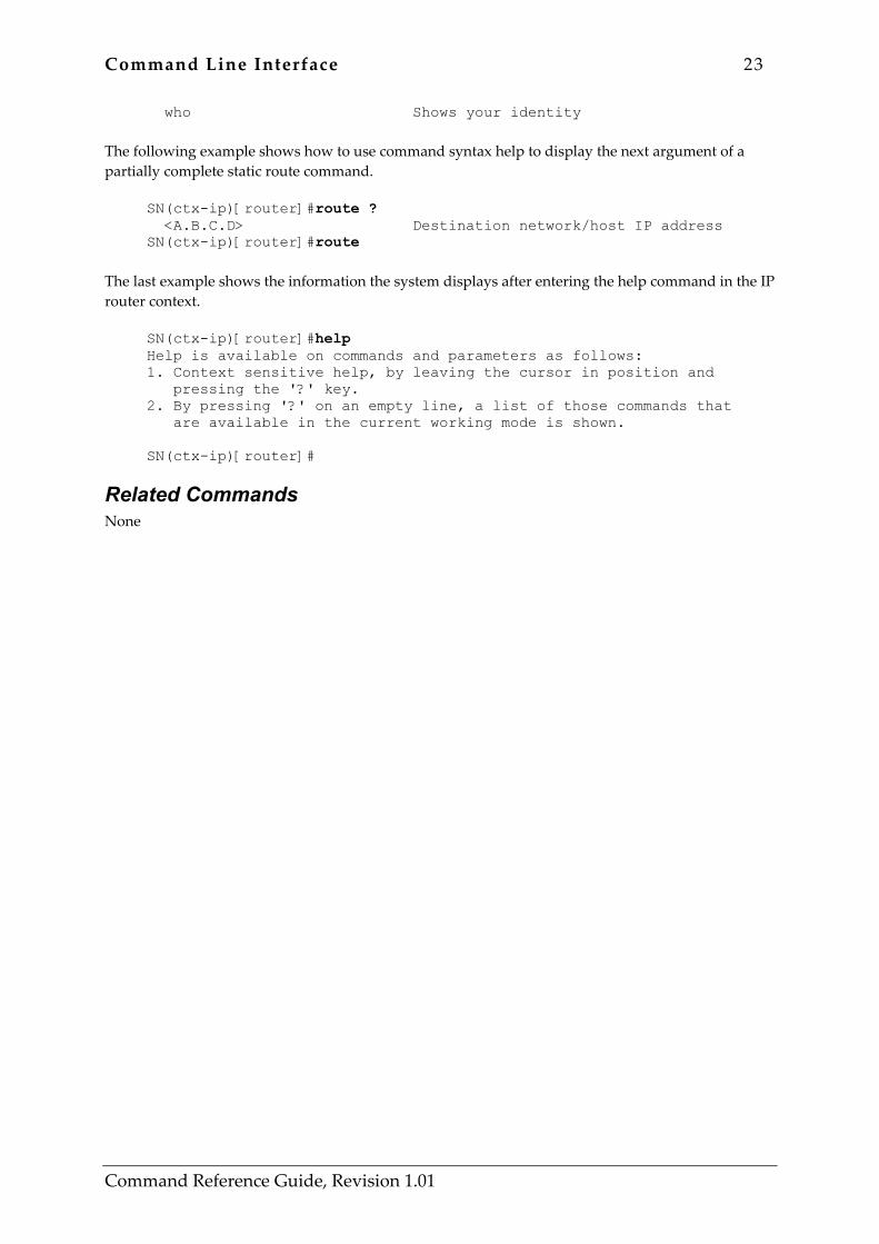
who Shows your identity The following example shows how to use command syntax help to display the next argument of a partially complete static route command.
SN(ctx-ip)[router]#route ? <A.B.C.D> Destination network/host IP address SN(ctx-ip)[router]#route
The last example shows the information the system displays after entering the help command in the IP router context.
SN(ctx-ip)[router]#help Help is available on commands and parameters as follows: 1. Context sensitive help, by leaving the cursor in position and pressing the '?' key. 2. By pressing '?' on an empty line, a list of those commands that are available in the current working mode is shown. SN(ctx-ip)[router]#
Related Commands None

24 Command Line Interface
Command Reference Guide, Revision 1.01
exit exit
Function Exits the current configuration mode and returns to the next highest level configuration mode. At the operator or administrator execution prompt, closes an active Telnet or console session and terminates the command shell.
Syntax Description This command has no keywords or arguments.
Default None
Mode The exit command is available in all execution and configuration modi.
Command Usage If you enter the exit command at the operator or administrator execution prompt in a Telnet or console session, you will terminate the command shell, log off of the SmartNode, and terminate the Telnet or console session. Warning: At the operator or administrator execution prompt the exit command, closes an active Telnet or console session and terminates the command shell without any user inquiry.
Example The following examples shows how an administrator uses the exit command to return from the onfiguration mode for an IP interface LAN to the next highest level, which is the context IP mode.
SN(if-ip)[LAN]#exit SN(ctx-ip)[router]#
Related Commands None
Operator Execution Mode 25
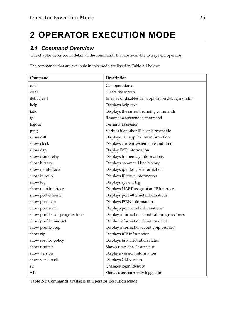
2 OPERATOR EXECUTION MODE 2.1 Command Overview This chapter describes in detail all the commands that are available to a system operator. The commands that are available in this mode are listed in Table 2-1 below:
Command Description
call clear debug call help jobs fg logout ping show call show clock show dsp show framerelay show history show ip interface show ip route show log show napt interface show port ethernet show port isdn show port serial show profile call-progress-tone show profile tone-set show profile voip show rip show service-policy show uptime show version show version cli su who
Call operations Clears the screen Enables or disables call application debug monitor Displays help text Displays the current running commands Resumes a suspended command Terminates session Verifies if another IP host is reachable Displays call application information Displays current system date and time Display DSP information Displays framerelay informations Displays command line history Displays ip interface information Displays IP route information Displays system log Displays NAPT usage of an IP interface Displays port ethernet informations Displays ISDN information Displays port serial informations Display information about call-progress tones Display information about tone sets Display information about voip profiles Displays RIP information Displays link arbitration status Shows time since last restart Displays version information Displays CLI version Changes login identity Shows users currently logged in
Table 2-1: Commands available in Operator Execution Mode
26 Operator Execution Mode
Command Reference Guide, Revision 1.01
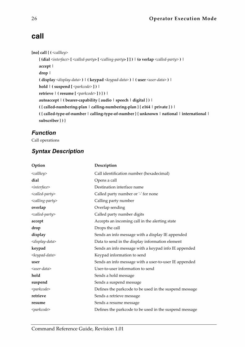
call [no] call { ( <callkey> { (dial <interface> [ <called-party> [ <calling-party> ] ] ) | (o verlap <called-party> ) | accept | drop | ( display <display-data> ) | ( keypad <keypad-data> ) | ( user <user-data> ) | hold | ( suspend [ <parkcode> ] ) | retrieve | ( resume [ <parkcode> ] ) } ) | autoaccept | ( bearer-capability { audio | speech | digital } ) | ( { called-numbering-plan | calling-numbering-plan } { e164 | private } ) | ( { called-type-of-number | calling-type-of-number } { unknown | national | international | subscriber } ) }
Function Call operations
Syntax Description Option Description
<callkey> dial <interface> <called-party> <calling-party> overlap <called-party> accept drop display <display-data> keypad <keypad-data> user <user-data> hold suspend <parkcode> retrieve resume <parkcode>
Call identification number (hexadecimal) Opens a call Destination interface name Called party number or '-' for none Calling party number Overlap sending Called party number digits Accepts an incoming call in the alerting state Drops the call Sends an info message with a display IE appended Data to send in the display information element Sends an info message with a keypad info IE appended Keypad information to send Sends an info message with a user-to-user IE appended User-to-user information to send Sends a hold message Sends a suspend message Defines the parkcode to be used in the suspend message Sends a retrieve message Sends a resume message Defines the parkcode to be used in the suspend message
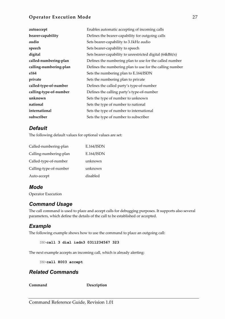
Operator Execution Mode 27
Command Reference Guide, Revision 1.01
autoaccept bearer-capability audio speech digital called-numbering-plan calling-numbering-plan e164 private called-type-of-number calling-type-of-number unknown national international subscriber
Enables automatic accepting of incoming calls Defines the bearer-capability for outgoing calls Sets bearer-capability to 3.1kHz audio Sets bearer-capability to speech Sets bearer-capability to unrestricted digital (64kBit/s) Defines the numbering plan to use for the called number Defines the numbering plan to use for the calling number Sets the numbering plan to E.164/ISDN Sets the numbering plan to private Defines the called party’s type-of-number Defines the calling party’s type-of-number Sets the type of number to unknown Sets the type of number to national Sets the type of number to international Sets the type of number to subscriber
Default The following default values for optional values are set: Called-numbering-plan E.164/ISDN
Calling-numbering-plan E.164/ISDN
Called-type-of-number unknown
Calling-type-of-number unknown
Auto-accept disabled
Mode Operator Execution
Command Usage The call command is used to place and accept calls for debugging purposes. It supports also several parameters, which define the details of the call to be established or accepted.
Example The following example shows how to use the command to place an outgoing call:
SN>call 3 dial isdn3 0311234567 323 The next example accepts an incoming call, which is already alerting:
SN>call 8003 accept
Related Commands Command Description

28 Operator Execution Mode
Command Reference Guide, Revision 1.01
debug call Enables the call application monitor to see the responses
debug session-control Enables the session-control monitor to see its activities
Operator Execution Mode 29
Command Reference Guide, Revision 1.01
clear clear
Function Clears the screen
Syntax Description Option Description
This command has no keywords or options
Default None
Mode Operator Execution
Command Usage Clears the screen of the terminal window you are currently logged in.
Example The following example clears the screen of the current terminal window:
SN>clear
Related Commands None
30 Operator Execution Mode
Command Reference Guide, Revision 1.01
debug call [no] debug call [ <detail> ]
Function Enables or disables call application debug monitor
Syntax Description Option Description
<detail> Detail level
Default None
Mode Operator Execution
Command Usage This monitor is used in conjunction with the call command to see the responses to call application activities.
Example The following example shows how to enable the monitor:
SN>debug call The next example shows how to disable the monitor:
SN>no debug call
Related Commands Command Description
call Establishes or accepts calls for debugging purposes
debug session-control Enables the session-cntrol monitor

Operator Execution Mode 31
Command Reference Guide, Revision 1.01
jobs jobs
Function Displays the current running commands
Syntax Description Option Description
This command has no keywords or options
Default None
Mode Operator Execution
Command Usage This command displays a list of current running CLI commands. Most of the configuration commands terminate immediately after configuring the system. However there are some commands that need some time to finish. Ping is one of them. Pressing Ctrl-Z can suspend a command like this, and the prompt is reprinted. Now the command continues running in the background. The jobs command lists all command that run in fore- or background.
Example The following example starts a ping process. After three replies the operator presses Ctrl-Z. The ping command continues in background and the prompt is reprinted. The invocation of the jobs command displays a list of all running commands:
SN>ping 172.16.1.10 Sending 10 ICMP echo requests to 172.16.1.10, timeout is 1 seconds: Reply from 172.16.1.10: Time 20ms Reply from 172.16.1.10: Time 10ms Reply from 172.16.1.10: Time 10ms % Suspended
At this point the operator presses Ctrl-Z
NOD_032_010(cfg)#Reply from 172.16.1.10: Time 10ms Reply from 172.16.1.10: Time 10ms
Now, the operator displays a list of all running commands using the jobs command
jobs * [run ] jobs 0 [bg ] ping NOD_032_010(cfg)#Reply from 172.16.1.10: Time 10ms Reply from 172.16.1.10: Time 10ms

32 Operator Execution Mode
Command Reference Guide, Revision 1.01
Reply from 172.16.1.10: Time 10ms Reply from 172.16.1.10: Time 10ms Reply from 172.16.1.10: Time 10ms Ping statistics for 172.16.1.10: Packets: Sent 10, Received 10, Lost 0 (0% loss), RTT: Minimum 10ms, Maximum 20ms, Average 11ms % Done [ping]
On the last line above the ping command in background is finished
Related Commands Command Description
fg Resumes a suspended command

Operator Execution Mode 33
Command Reference Guide, Revision 1.01
fg fg <job>
Function Resumes a suspended command
Syntax Description Option Description
<job>
Job ID of the command to be resumed. The job ID is displayed by the jobs command.
Default None
Mode Operator Execution
Command Usage This command resumes a suspended command. Most of the configuration commands terminate immediately after configuring the system. However there are some commands that need some time to finish. Ping is one of them. Pressing Ctrl-Z can suspend a command like this, and the prompt is reprinted. Now the command continues running in the background. The fg command resumes a background command and brings it to foreground again.
Example The following example starts a ping process. After three replies the operator presses Ctrl-Z. The ping command continues in background and the prompt is reprinted. The invocation of the jobs command displays a list of all running commands. The ping command has job ID 0 and is resumed using the fg command.
SN>jobs fg Sending 10 ICMP echo requests to 172.16.1.10, timeout is 1 seconds: Reply from 172.16.1.10: Time 20ms Reply from 172.16.1.10: Time 10ms Reply from 172.16.1.10: Time 10ms
At this point the operator presses Ctrl-Z
% Suspended NOD_032_010(cfg)#Reply from 172.16.1.10: Time 10ms Reply from 172.16.1.10: Time 10ms
Now, the operator displays a list of all running commands using the jobs command
jobs * [run ] jobs 0 [bg ] ping
34 Operator Execution Mode
Command Reference Guide, Revision 1.01
NOD_032_010(cfg)#Reply from 172.16.1.10: Time 10ms Reply from 172.16.1.10: Time 10ms
Finally, the operator resumes the ping command with job ID 0
fg 0 % Resumed [ping] Reply from 172.16.1.10: Time 10ms Reply from 172.16.1.10: Time 10ms Reply from 172.16.1.10: Time 10ms Ping statistics for 172.16.1.10: Packets: Sent 10, Received 10, Lost 0 (0% loss), RTT: Minimum 10ms, Maximum 20ms, Average 11ms
Related Commands Command Description
jobs Displays the current running commands
Operator Execution Mode 35
Command Reference Guide, Revision 1.01
logout logout
Function Terminates session
Syntax Description Option Description
This command has no keywords or options
Default None
Mode Operator Execution
Command Usage This command logs off the system and terminates the current CLI session.
Example The following example a user logs off the system:
SN>logout Press ‘yes’ to logout, ‘no’ to cancel : yes Goodbye
Related Commands Command Description
exit Exits the current mode
36 Operator Execution Mode
Command Reference Guide, Revision 1.01
ping ping <address> [ <number> ] [ timeout <seconds> ]
Function Verifies if another IP host is reachable
Syntax Description Option Description
<address> IP address of the host to ping in the form A.B.C.D.
<number> Optional. The number of ping packets to send. The valid range is 1 to 10000; the default is 5.
timeout To specify the time to wait for a response.
<seconds> Optional. Time in seconds to wait for a response. The valid range is 1 to 100; the default is 1.
Default This command sends five ping packets to the specified host, using a timeout value of one second.
Mode Operator Execution
Command Usage Ping is a diagnostic tool widely used to test and debug network connectivity. Ping sends ICMP echo request packet to the specified host and expects ICMP echo reply packets from the host within the specified timeout. The command repeats this action as many times as you specified with the <number> option.
Example The following example shows the common usage of ping:
SN>ping 172.16.1.10 The next example shows a more extended usage of ping. The command sends 10 ping packets to the host and for each expects an answer within 2 seconds:
SN>ping 170.16.1.10 10 timeout 2 The output of the ping command depends whether the host is reachable or not and whether the host is up and answers to the ping packets. If the network could not find a route to the specified host, the ping command produces the following output:

Operator Execution Mode 37
Command Reference Guide, Revision 1.01
SN>ping 172.16.1.10 % No route to host
If the network could find a route to the specified host, but the host does not answer (e.g. because it is switched off), the ping reports that it did not receive a reply for each sent ping packet:
SN>ping 172.16.1.10 Sending 5 ICMP echo requests to 172.16.1.10, timeout is 1 seconds: Request timed out. Request timed out. Request timed out. Request timed out. Request timed out. Ping statistics for 172.16.1.10: Packets: Sent 5, Received 0, Lost 5 (100% loss),
If the host is reachable and responds to the ping packets, the ping command prints out the round-trip-delay between the pinging source and the pinged target host:
SN>ping 172.16.1.10 Sending 5 ICMP echo requests to 172.16.1.10, timeout is 1 seconds: Reply from 172.16.1.10: Time 20ms Reply from 172.16.1.10: Time 20ms Reply from 172.16.1.10: Time 30ms Reply from 172.16.1.10: Time 20ms Reply from 172.16.1.10: Time 20ms Ping statistics for 172.16.1.10: Packets: Sent 5, Received 5, Lost 0 (0% loss), RTT: Minimum 20ms, Maximum 30ms, Average 22ms
Related Commands None
38 Operator Execution Mode
Command Reference Guide, Revision 1.01
show call show call { config | sessions } [ <detail> ]
Function Displays call application information
Syntax Description Option Description
config sessions <detail>
Displays the call-application configuration Displays information about running call application sessions Detail level that is a value in the range from 0 to 5
Default None
Mode Operator Execution
Command Usage This command is used to display the actual running call application sessions.
Example The following examples displays the call-application configuration:
SN>show call config The next example displays information about running call application sessions:
SN>show call sessions 5
Related Commands None
Operator Execution Mode 39
Command Reference Guide, Revision 1.01
show clock show clock
Function Displays current system date and time
Syntax Description Option Description
clock Displays current system date and time in the format yyyy-mm-ddThh:mm:ss
Default None
Mode Operator Execution
Command Usage This command displays the current system date and time.
Example The following example displays the current system date and time:
SN>show clock 2002-04-29T15:23:24
Related Commands Command Description
clock set Sets the system clock
sntp-client Start/stop/configure SNTP client
40 Operator Execution Mode
Command Reference Guide, Revision 1.01
show dsp show dsp { <slot> | ( statistics <slot> ) | ( channel statistics <slot> ) | ( sw-version <slot> ) | ( test-result <slot> ) }
Function Display DSP information
Syntax Description Option Description
dsp <slot> statistics <slot> channel statistics <slot> sw-version <slot> test-result <slot>
Display DSP information The number of the slot Displays DSP device statistics The number of the slot Displays DSP channel information Displays DSP channel statistics The number of the slot Displays DSP software version of the current DSP code The number of the slot Displays DSP self test results of the last test performed The number of the slot
Default None
Mode Operator Execution
Command Usage This command is used to verify DSP configuration, to verify the DSP software version running and to verify the latest self-test result. Warning: DSP statistics can only be read with special software!
Example The following examples display DSP information on slot 0 and the latest DSP self test result on slot 1:
SN>show dsp 0 SN>show dsp test-result 1
Related Commands None
Operator Execution Mode 41
Command Reference Guide, Revision 1.01
show framerelay show framerelay [ pvc <print-dlci> ]
Function Displays Frame Relay informations
Syntax Description Option Description
pvc <print-dlci>
Displays Frame Relay PVC informations Enter DLCI
Default None
Mode Operator Execution
Command Usage Since Frame Relay configuration for the serial interface is complex and requires many commands, it is helpful to list the frame relay configuration on screen.
Example The following example displays the Frame Relay configuration settings for the serial interface.
SN>port serial 0 0 SN(prt-ser)[0/0]# show framerelay Framerelay Configuration: Port LMI-Type Keepalive Fragmentation ---------------------------------------------------------- serial 0 0 0 ansi 10 enabled PVC Configuration: Port DLCI State Encaps Binding ---------------------------------------------------- serial 0 0 0 1 open rfc1490 wan@router
Related Commands None
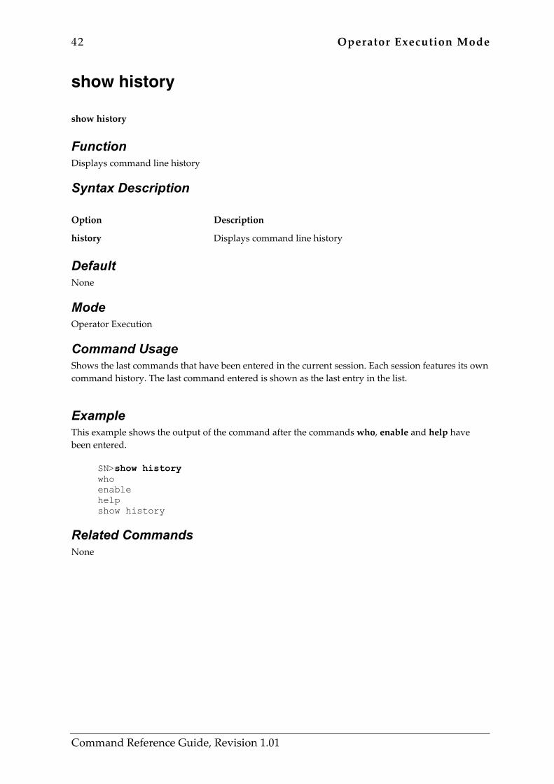
42 Operator Execution Mode
Command Reference Guide, Revision 1.01
show history show history
Function Displays command line history
Syntax Description Option Description
history Displays command line history
Default None
Mode Operator Execution
Command Usage Shows the last commands that have been entered in the current session. Each session features its own command history. The last command entered is shown as the last entry in the list.
Example This example shows the output of the command after the commands who, enable and help have been entered.
SN>show history who enable help show history
Related Commands None
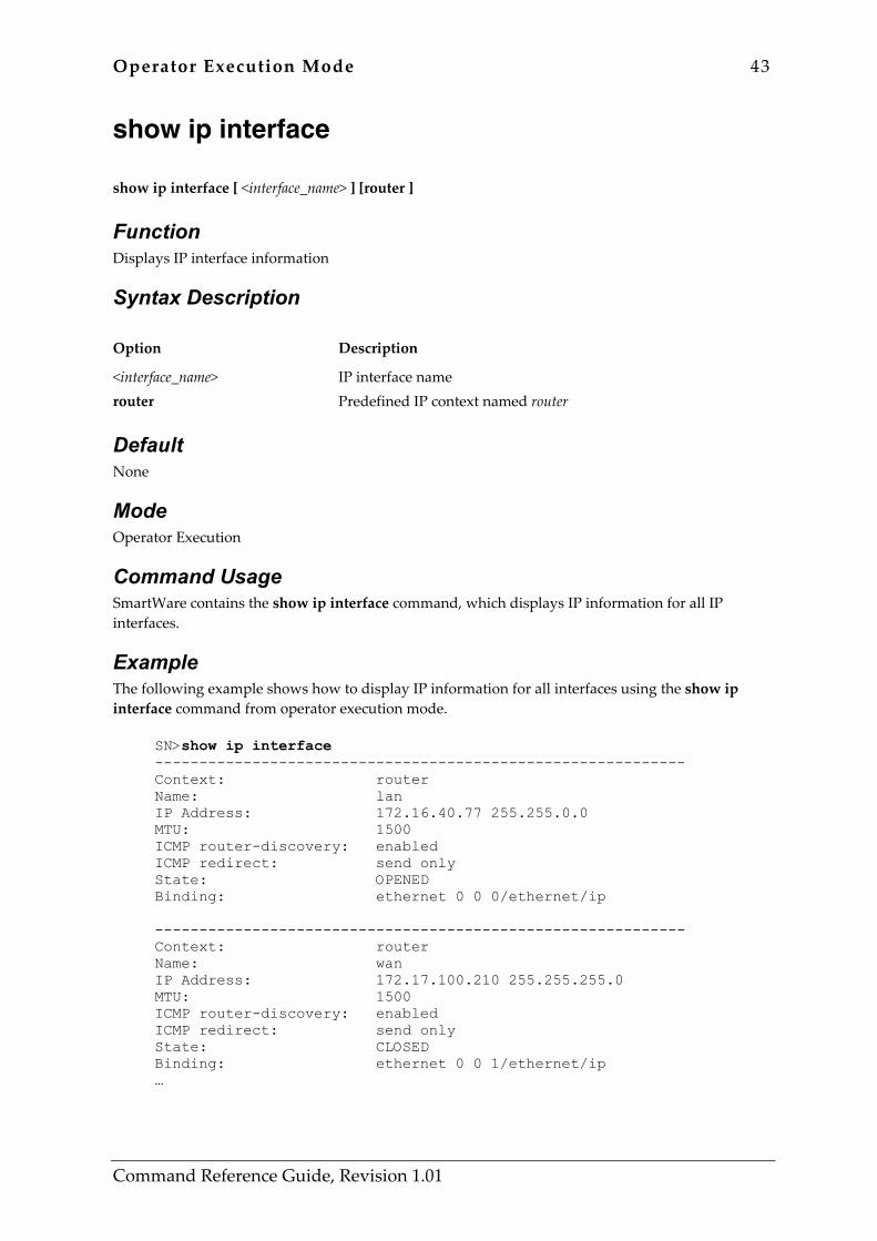
Operator Execution Mode 43
Command Reference Guide, Revision 1.01
show ip interface show ip interface [ <interface_name> ] [router ]
Function Displays IP interface information
Syntax Description Option Description
<interface_name> router
IP interface name Predefined IP context named router
Default None
Mode Operator Execution
Command Usage SmartWare contains the show ip interface command, which displays IP information for all IP interfaces.
Example The following example shows how to display IP information for all interfaces using the show ip interface command from operator execution mode.
SN>show ip interface ------------------------------------------------------------ Context: router Name: lan IP Address: 172.16.40.77 255.255.0.0 MTU: 1500 ICMP router-discovery: enabled ICMP redirect: send only State: OPENED Binding: ethernet 0 0 0/ethernet/ip ------------------------------------------------------------ Context: router Name: wan IP Address: 172.17.100.210 255.255.255.0 MTU: 1500 ICMP router-discovery: enabled ICMP redirect: send only State: CLOSED Binding: ethernet 0 0 1/ethernet/ip …

44 Operator Execution Mode
Command Reference Guide, Revision 1.01
Related Commands None
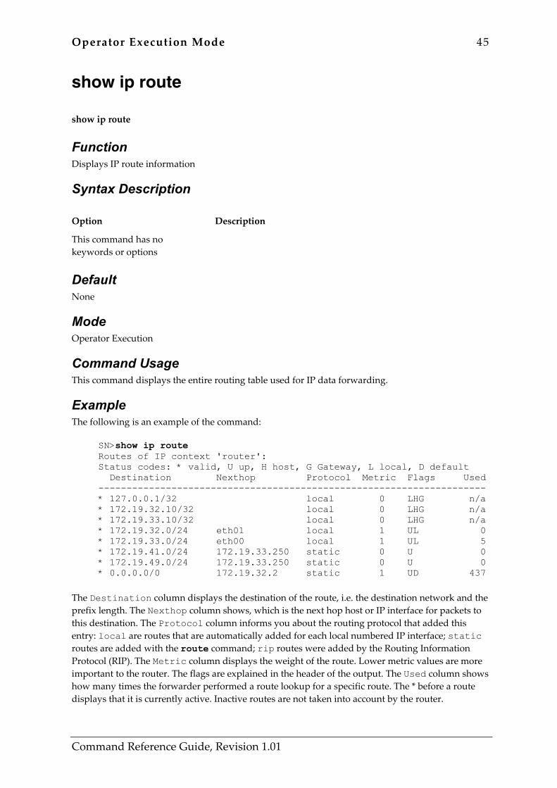
Operator Execution Mode 45
Command Reference Guide, Revision 1.01
show ip route show ip route
Function Displays IP route information
Syntax Description Option Description
This command has no keywords or options
Default None
Mode Operator Execution
Command Usage This command displays the entire routing table used for IP data forwarding.
Example The following is an example of the command:
SN>show ip route Routes of IP context 'router': Status codes: * valid, U up, H host, G Gateway, L local, D default Destination Nexthop Protocol Metric Flags Used --------------------------------------------------------------------- * 127.0.0.1/32 local 0 LHG n/a * 172.19.32.10/32 local 0 LHG n/a * 172.19.33.10/32 local 0 LHG n/a * 172.19.32.0/24 eth01 local 1 UL 0 * 172.19.33.0/24 eth00 local 1 UL 5 * 172.19.41.0/24 172.19.33.250 static 0 U 0 * 172.19.49.0/24 172.19.33.250 static 0 U 0 * 0.0.0.0/0 172.19.32.2 static 1 UD 437
The Destination column displays the destination of the route, i.e. the destination network and the prefix length. The Nexthop column shows, which is the next hop host or IP interface for packets to this destination. The Protocol column informs you about the routing protocol that added this entry: local are routes that are automatically added for each local numbered IP interface; static routes are added with the route command; rip routes were added by the Routing Information Protocol (RIP). The Metric column displays the weight of the route. Lower metric values are more important to the router. The flags are explained in the header of the output. The Used column shows how many times the forwarder performed a route lookup for a specific route. The * before a route displays that it is currently active. Inactive routes are not taken into account by the router.

46 Operator Execution Mode
Command Reference Guide, Revision 1.01
Related Commands Command Description
route Configures static IP routes
rip Configures the routing information protocol
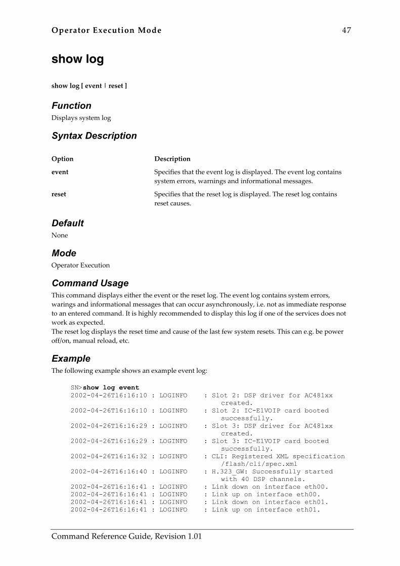
Operator Execution Mode 47
Command Reference Guide, Revision 1.01
show log show log [ event | reset ]
Function Displays system log
Syntax Description Option Description
event Specifies that the event log is displayed. The event log contains system errors, warnings and informational messages.
reset Specifies that the reset log is displayed. The reset log contains reset causes.
Default None
Mode Operator Execution
Command Usage This command displays either the event or the reset log. The event log contains system errors, warings and informational messages that can occur asynchronously, i.e. not as immediate response to an entered command. It is highly recommended to display this log if one of the services does not work as expected. The reset log displays the reset time and cause of the last few system resets. This can e.g. be power off/on, manual reload, etc.
Example The following example shows an example event log:
SN>show log event 2002-04-26T16:16:10 : LOGINFO : Slot 2: DSP driver for AC481xx created. 2002-04-26T16:16:10 : LOGINFO : Slot 2: IC-E1VOIP card booted successfully. 2002-04-26T16:16:29 : LOGINFO : Slot 3: DSP driver for AC481xx created. 2002-04-26T16:16:29 : LOGINFO : Slot 3: IC-E1VOIP card booted successfully. 2002-04-26T16:16:32 : LOGINFO : CLI: Registered XML specification /flash/cli/spec.xml 2002-04-26T16:16:40 : LOGINFO : H.323_GW: Successfully started with 40 DSP channels. 2002-04-26T16:16:41 : LOGINFO : Link down on interface eth00. 2002-04-26T16:16:41 : LOGINFO : Link up on interface eth00. 2002-04-26T16:16:41 : LOGINFO : Link down on interface eth01. 2002-04-26T16:16:41 : LOGINFO : Link up on interface eth01.

48 Operator Execution Mode
Command Reference Guide, Revision 1.01
2002-04-26T16:16:59 : LOGINFO : Warm start. The next example displays the output of a typical reset log:
SN>show log reset 2002-04-18T15:06:38 : Target Shell 2002-04-18T20:58:30 : SW Watchdog: 2002-04-19T09:45:04 : Target Shell 2002-04-19T10:54:40 : Target Shell 2002-04-19T13:33:41 : Target Shell 2002-04-25T14:44:12 : Target Shell 2002-04-25T15:04:08 : Target Shell 2002-04-26T14:46:06 : Target Shell 2002-04-26T16:16:29 : Target Shell
Related Commands None
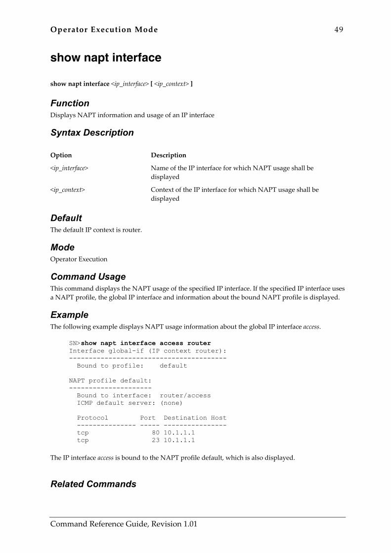
Operator Execution Mode 49
Command Reference Guide, Revision 1.01
show napt interface show napt interface <ip_interface> [ <ip_context> ]
Function Displays NAPT information and usage of an IP interface
Syntax Description Option Description
<ip_interface> Name of the IP interface for which NAPT usage shall be displayed
<ip_context> Context of the IP interface for which NAPT usage shall be displayed
Default The default IP context is router.
Mode Operator Execution
Command Usage This command displays the NAPT usage of the specified IP interface. If the specified IP interface uses a NAPT profile, the global IP interface and information about the bound NAPT profile is displayed.
Example The following example displays NAPT usage information about the global IP interface access.
SN>show napt interface access router Interface global-if (IP context router): ---------------------------------------- Bound to profile: default NAPT profile default: --------------------- Bound to interface: router/access ICMP default server: (none) Protocol Port Destination Host --------------- ----- ---------------- tcp 80 10.1.1.1 tcp 23 10.1.1.1
The IP interface access is bound to the NAPT profile default, which is also displayed.
Related Commands

50 Operator Execution Mode
Command Reference Guide, Revision 1.01
Command Description
show profile napt Displays NAPT profile information
profile napt Network Address Port Translation profile
use profile napt Lets a global IP interface use a NAPT profile
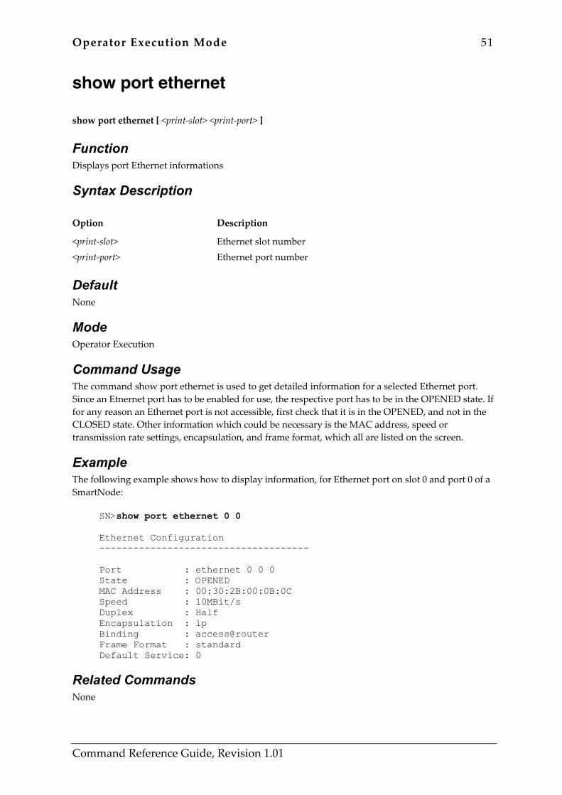
Operator Execution Mode 51
Command Reference Guide, Revision 1.01
show port ethernet show port ethernet [ <print-slot> <print-port> ]
Function Displays port Ethernet informations
Syntax Description Option Description
<print-slot> <print-port>
Ethernet slot number Ethernet port number
Default None
Mode Operator Execution
Command Usage The command show port ethernet is used to get detailed information for a selected Ethernet port. Since an Etnernet port has to be enabled for use, the respective port has to be in the OPENED state. If for any reason an Ethernet port is not accessible, first check that it is in the OPENED, and not in the CLOSED state. Other information which could be necessary is the MAC address, speed or transmission rate settings, encapsulation, and frame format, which all are listed on the screen.
Example The following example shows how to display information, for Ethernet port on slot 0 and port 0 of a SmartNode:
SN>show port ethernet 0 0 Ethernet Configuration ------------------------------------- Port : ethernet 0 0 0 State : OPENED MAC Address : 00:30:2B:00:0B:0C Speed : 10MBit/s Duplex : Half Encapsulation : ip Binding : access@router Frame Format : standard Default Service: 0
Related Commands None
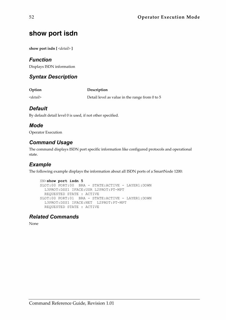
52 Operator Execution Mode
Command Reference Guide, Revision 1.01
show port isdn show port isdn [ <detail> ]
Function Displays ISDN information
Syntax Description Option Description
<detail> Detail level as value in the range from 0 to 5
Default By default detail level 0 is used, if not other specified.
Mode Operator Execution
Command Usage The command displays ISDN port specific information like configured protocols and operational state.
Example The following example displays the information about all ISDN ports of a SmartNode 1200:
SN>show port isdn 5 SLOT:00 PORT:00 BRA - STATE:ACTIVE - LAYER1:DOWN L3PROT:DSS1 IFACE:USR L2PROT:PT-MPT REQUESTED STATE : ACTIVE SLOT:00 PORT:01 BRA - STATE:ACTIVE - LAYER1:DOWN L3PROT:DSS1 IFACE:NET L2PROT:PT-MPT REQUESTED STATE : ACTIVE
Related Commands None
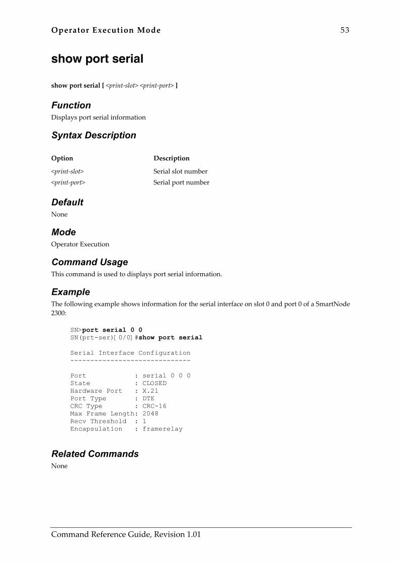
Operator Execution Mode 53
Command Reference Guide, Revision 1.01
show port serial show port serial [ <print-slot> <print-port> ]
Function Displays port serial information
Syntax Description Option Description
<print-slot> <print-port>
Serial slot number Serial port number
Default None
Mode Operator Execution
Command Usage This command is used to displays port serial information.
Example The following example shows information for the serial interface on slot 0 and port 0 of a SmartNode 2300:
SN>port serial 0 0 SN(prt-ser)[0/0]#show port serial Serial Interface Configuration ------------------------------ Port : serial 0 0 0 State : CLOSED Hardware Port : X.21 Port Type : DTE CRC Type : CRC-16 Max Frame Length: 2048 Recv Threshold : 1 Encapsulation : framerelay
Related Commands None
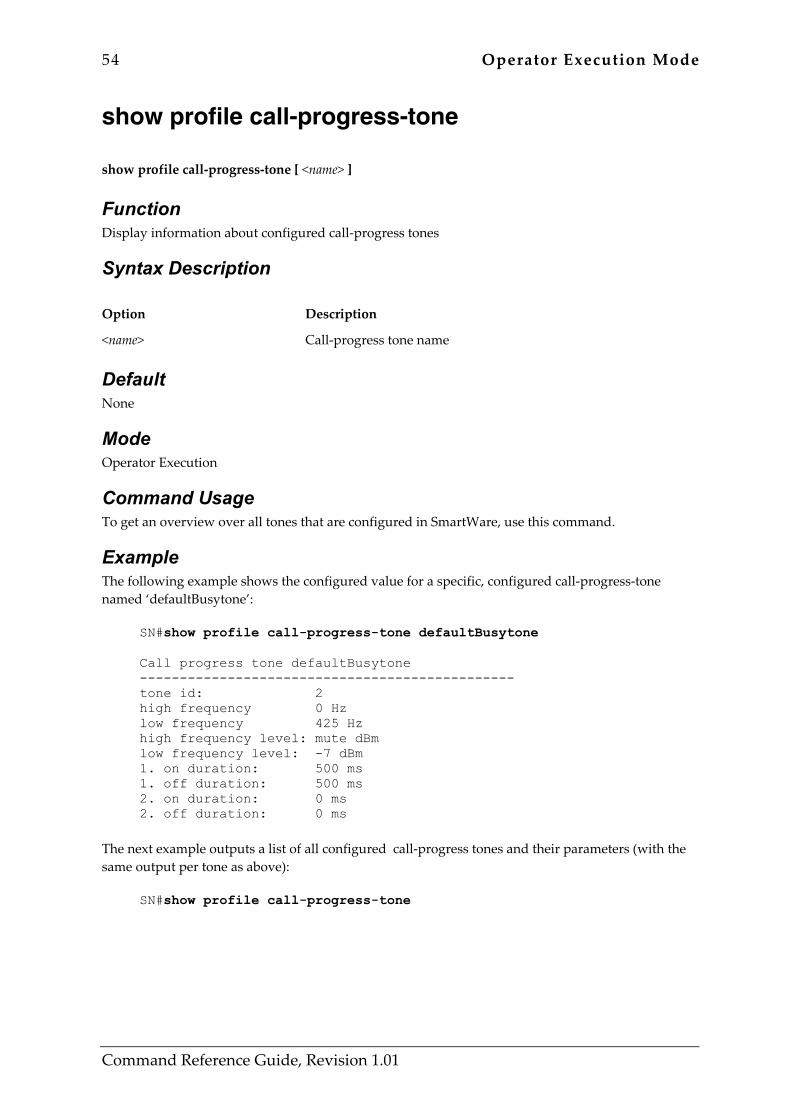
54 Operator Execution Mode
Command Reference Guide, Revision 1.01
show profile call-progress-tone show profile call-progress-tone [ <name> ]
Function Display information about configured call-progress tones
Syntax Description Option Description
<name> Call-progress tone name
Default None
Mode Operator Execution
Command Usage To get an overview over all tones that are configured in SmartWare, use this command.
Example The following example shows the configured value for a specific, configured call-progress-tone named ‘defaultBusytone’:
SN#show profile call-progress-tone defaultBusytone Call progress tone defaultBusytone ----------------------------------------------- tone id: 2 high frequency 0 Hz low frequency 425 Hz high frequency level: mute dBm low frequency level: -7 dBm 1. on duration: 500 ms 1. off duration: 500 ms 2. on duration: 0 ms 2. off duration: 0 ms
The next example outputs a list of all configured call-progress tones and their parameters (with the same output per tone as above):
SN#show profile call-progress-tone

Operator Execution Mode 55
Command Reference Guide, Revision 1.01
Related Commands Command Description
profile call-progress-tone Enter call-progress tone configuration
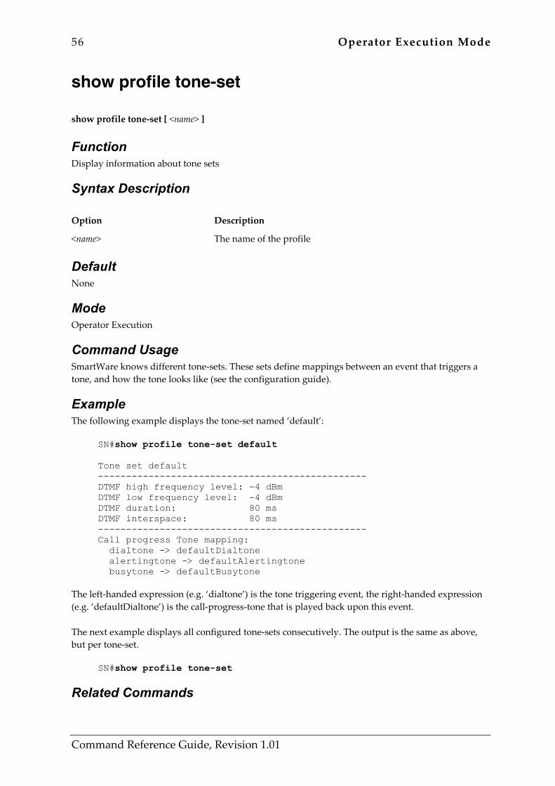
56 Operator Execution Mode
Command Reference Guide, Revision 1.01
show profile tone-set show profile tone-set [ <name> ]
Function Display information about tone sets
Syntax Description Option Description
<name> The name of the profile
Default None
Mode Operator Execution
Command Usage SmartWare knows different tone-sets. These sets define mappings between an event that triggers a tone, and how the tone looks like (see the configuration guide).
Example The following example displays the tone-set named ‘default’:
SN#show profile tone-set default Tone set default ------------------------------------------------ DTMF high frequency level: -4 dBm DTMF low frequency level: -4 dBm DTMF duration: 80 ms DTMF interspace: 80 ms ------------------------------------------------ Call progress Tone mapping: dialtone -> defaultDialtone alertingtone -> defaultAlertingtone busytone -> defaultBusytone
The left-handed expression (e.g. ‘dialtone’) is the tone triggering event, the right-handed expression (e.g. ‘defaultDialtone’) is the call-progress-tone that is played back upon this event. The next example displays all configured tone-sets consecutively. The output is the same as above, but per tone-set.
SN#show profile tone-set
Related Commands

Operator Execution Mode 57
Command Reference Guide, Revision 1.01
Command Description
profile tone-set Enter tone set profile configuration
use tone-set-profile Link a tone-set profile to the selected interface
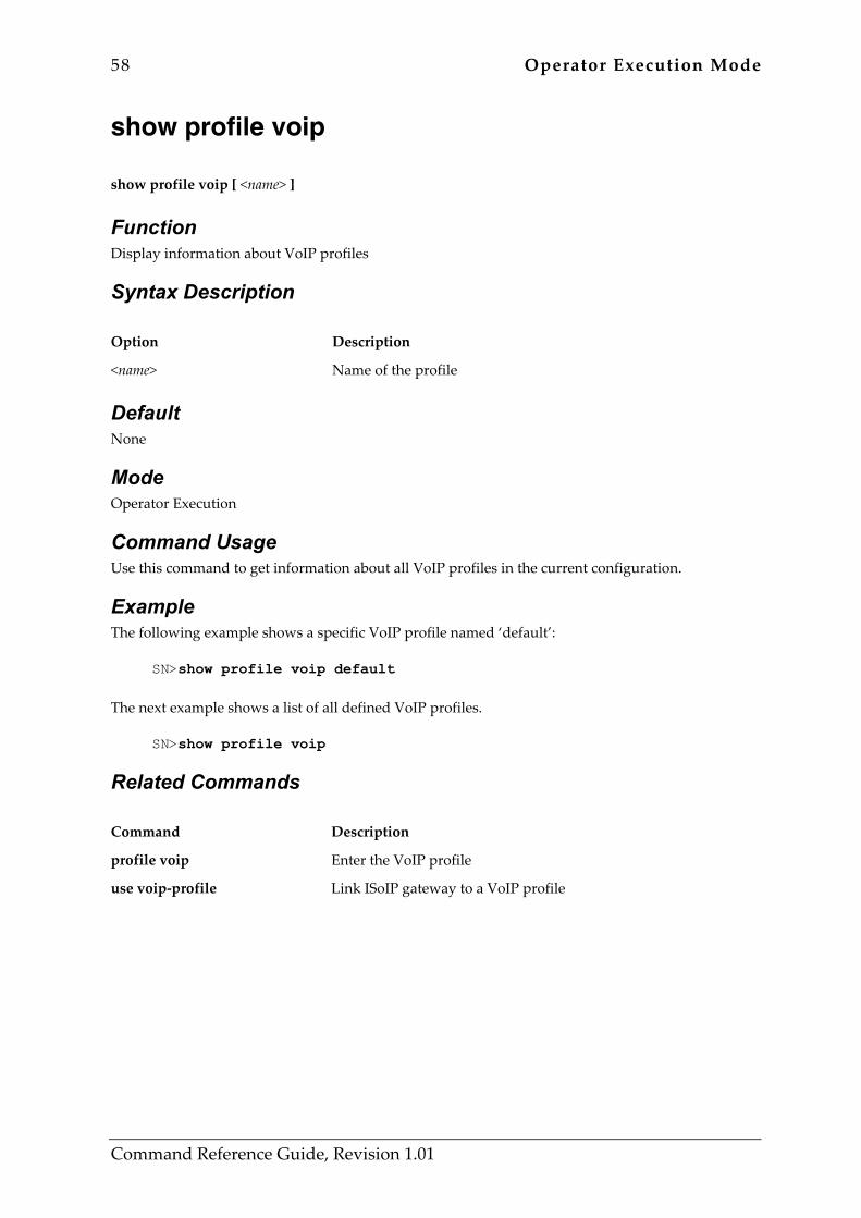
58 Operator Execution Mode
Command Reference Guide, Revision 1.01
show profile voip show profile voip [ <name> ]
Function Display information about VoIP profiles
Syntax Description Option Description
<name> Name of the profile
Default None
Mode Operator Execution
Command Usage Use this command to get information about all VoIP profiles in the current configuration.
Example The following example shows a specific VoIP profile named ‘default’:
SN>show profile voip default The next example shows a list of all defined VoIP profiles.
SN>show profile voip
Related Commands Command Description
profile voip Enter the VoIP profile
use voip-profile Link ISoIP gateway to a VoIP profile
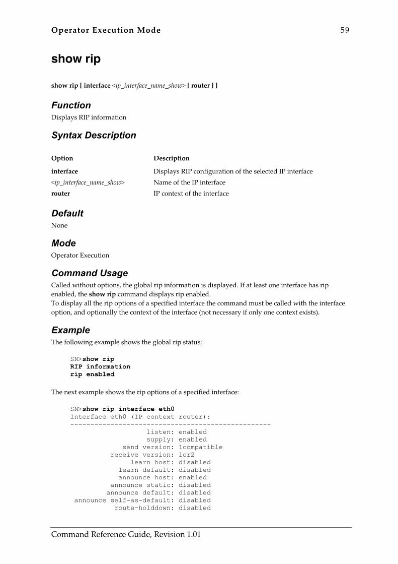
Operator Execution Mode 59
Command Reference Guide, Revision 1.01
show rip show rip [ interface <ip_interface_name_show> [ router ] ]
Function Displays RIP information
Syntax Description Option Description
interface <ip_interface_name_show> router
Displays RIP configuration of the selected IP interface Name of the IP interface IP context of the interface
Default None
Mode Operator Execution
Command Usage Called without options, the global rip information is displayed. If at least one interface has rip enabled, the show rip command displays rip enabled. To display all the rip options of a specified interface the command must be called with the interface option, and optionally the context of the interface (not necessary if only one context exists).
Example The following example shows the global rip status:
SN>show rip RIP information rip enabled
The next example shows the rip options of a specified interface:
SN>show rip interface eth0 Interface eth0 (IP context router): -------------------------------------------------- listen: enabled supply: enabled send version: 1compatible receive version: 1or2 learn host: disabled learn default: disabled announce host: enabled announce static: disabled announce default: disabled announce self-as-default: disabled route-holddown: disabled
60 Operator Execution Mode
Command Reference Guide, Revision 1.01
poison-reverse: disabled auto-summary: disabled split-horizon: enabled default-route-value: 0 --------------------------------------------------
Related Commands Command Description
rip announce rip announce host rip announce static rip auto-summary rip default-route-value rip learn default rip learn host rip listen rip poison-reverse rip receive version rip route-holddown rip send version rip split-horizon rip supply
Enable RIP announcing Enable RIP announce IP host routes Enable RIP announce static IP routes Enable RIP auto summarization Set the RIP default route metric Enable RIP learning using default route advertised by a RIP neighbor Enable accepting of received IP host routes Enable receive RIP on an interface Enable the poison reverse algorithm Select the receive RIP version on an interface Enable holding down aged routes on an interface Select the send RIP version on an interface Enable RIP split-horizon processing on an interface Enable send RIP on an interface
Operator Execution Mode 61
Command Reference Guide, Revision 1.01
show service-policy show service-policy [ interface <interface-name> [router ] ]
Function Display the status of running link arbitration
Syntax Description Option Description
interface <interface-name> router
Selected IP interface IP interface name IP context of the interface
Default None
Mode Operator Execution
Command Usage The show profile service-policy command displays link scheduling profile information of an existing service-policy profile.
Example The following example shows how to display link scheduling profile information of a user defined service-policy profile named VoIP_Layer2_CoS.
SN>show profile service-policy VoIP_Layer2_CoS VoIP_Layer2_CoS default (mark layer 2 cos -1)
Related Commands None
62 Operator Execution Mode
Command Reference Guide, Revision 1.01
show uptime show uptime
Function Show system uptime since last restart
Syntax Description Option Description
This command has no keywords or options
Default None
Mode Operator Execution
Command Usage Show system uptime since last restart.
Example
SN>show uptime SN>The system is up for 30 days, 8 hours, 14 minutes, 37 seconds
Related Commands None
Operator Execution Mode 63
Command Reference Guide, Revision 1.01
show version show version
Function Displays version information
Syntax Description Option Description
This command has no keywords or options
Default None
Mode Operator Execution
Command Usage To display different informations about the system hardware, the software version, the PLD versions, the interface cards use the show version command.
Example The following is sample output from the show version command on a SmartNode 1200:
SN>show version Productname : SN1X00 Software Version : SmartWare R2.00 BUILD21137 Supplier : Inalp Networks Inc. Provider : Pink Telecom Solutions Subscriber : MegaSoft Inc. Information for Slot 0: SN1X00 (Admin State: Application Started, Real State: Application Started) Hardware Version : 4, 1 Serial number : 100000020138 Software Version : SmartWare R2.00 BUILD21137
The following is sample output from the show version command on a SmartNode Sn2300 with an IC-4BRV VoIP interface card:
SN>show version Productname : SN2300 Software Version : SmartWare R2.00 BUILD22051 Supplier : Inalp Networks Inc. Provider : Pink Telecom Solutions
64 Operator Execution Mode
Command Reference Guide, Revision 1.01
Subscriber : MegaSoft Inc. Information for Slot 0: SN2300 (Admin State: Application Started, Real State: Application Started) Hardware Version : 2, 1 Serial number : 100000023116 PLD Version : 0x23020204 Software Version : SmartWare R2.00 BUILD22051 Information for Slot 1: this Slot is empty Information for Slot 2: IC-4BRV (Admin State: Application Started, Real State: Application Started) Hardware Version : 2, 1 Serial number : 100000022688 Manufactor number: 0105305437 Production date : 0003-02 PLD Version : 0x00170002 Software Version : Build 24052, min required : Build 24050 Loader Version : Build 39, min required: Build 39 Information for Slot 3: this Slot is empty
Related Commands None
Operator Execution Mode 65
Command Reference Guide, Revision 1.01
show version cli show version cli
Function Displays CLI version
Syntax Description Option Description
This command has no keywords or options
Default None
Mode Operator Execution
Command Usage This command shows the version of the command interpreter.
Example
SN(cfg)>show version cli CLI version : 2.00
Related Commands Command Description
cli version Selects CLI version
66 Operator Execution Mode
Command Reference Guide, Revision 1.01
su su <account>
Function Changes login identity
Syntax Description Option Description
<account>
Name of the account to which the current session shall be changed.
Default None
Mode Operator Execution
Command Usage This command can be used to change the login identity of the current session. If an operator logs in and later wishes to configure the system, she may change her identity to an adminsitrator instead of logging off and logging in again as administrator.
Example The following example shows an operator logging in and changing its identity to an administrator:
login:test password: SN(cfg)>su administrator Enter password: SN(cfg)>
Related Commands Command Description
logout Terminates session
show accounts Displays administrator and operator accounts
Operator Execution Mode 67
Command Reference Guide, Revision 1.01
who who
Function Shows users currently logged in
Syntax Description Option Description
This command has no keywords or options
Default None
Mode Operator Execution
Command Usage To display who is logged in or to see more detailed information about users and process states the who command provides this information. Note: Depending on execution mode the command displays varying information. In operator execution mode only the user name being used at the moment is reported, which helps checking the identity. In administrator execution mode the command output is more detailed and shows information about all users currently logged in, user name, state, idle time and location.
Example The first example shows the output of the who command, when entered as operator.
SN>who You are operator rene
The second example shows the output of the who command when entered by an administrator. In this case the command displays all users that are currently logged in. The asterisk denotes the current user (that is you). State represents the actual running condition of the user, which can be logout, login, exec and config.
SN#who ID User name State Idle Location * 0 administrator exec 00:00:00 172.31.14.100:3952 1 rene config 00:00:39 172.31.14.192:3330
Related Commands None

Administrator Execution Mode 68
Command Reference Guide, Revision 1.01
3 ADMINISTRATOR EXECUTION MODE 3.1 Command Overview This chapter describes in detail all the commands available to you as a system administrator. In addition to all operator commands, additional commands are available to the administrator that enable complete configuration and control of the system. The commands that are available to you in this mode are listed in Table 3-1 below:
Command Description
copy debug acl debug all debug dsp debug gateway h323 debug gateway isoip debug isdn debug session-control debug session-router debug sntp client debug voip-data enable end erase reload session-control close show show accounts show context cs show crc show gateway h323 show gateway isoip show isdn show log supervisor show profile acl show profile napt show profile service-policy show service-policy show session-control show snmp show sntp-client
Copies configurations and software images Enables or disables access-list debug monitor Enables or disables all debug monitors Enables or disables DSP debug monitor Enables or disables H.323 gateway debug monitor Enables or disables ISoIP gateway debug monitor Enables or disables ISDN debug monitor Enables or disables session-control debug monitor Enables or disables session-router debug monitor Enables or disables SNTP client debug monitor Enables or disables voip debug monitor Enters administration execution mode Exit the current configuration mode Erases persistent configurations Restarts the system Close open sessions Displays system information Displays administrator and operator accounts Displays circuit context information Displays checksum of a configuration Displays H.323 gateway information Displays isoip information Displays ISDN information Displays system state before last restart Displays access-list profile information Displays NAPT profile information Displays link scheduling profile information Displays link scheduler information Displays session-control information Displays system information related to SNMP Displays information and status of SNTP client
Table 3-1: Commands available in Administrator Execution Mode
Administrator Execution Mode 69
Command Reference Guide, Revision 1.01
copy copy <source> <destination>
Function Copies configurations and software images
Syntax Description Option Description
<source> <destination>
URL of the source file that is to be copied. URL of the destination of the copy operation.
Default None
Mode Administrator Execution
Command Usage When referring to a configuration file on the local system, the URL takes the following form: nvram:configfilename When referring to the current running configuration, the URL takes the following form: system:running-config When referring to a TFTP server, the URL takes the following form, where A.B.C.D is the IP address of the TFTP server: tftp://A.B.C.D[/directory]/filename When referring to the image of the system for batch file download, the destination URL takes the following form: flash: Note: The system provides a number of shortcuts for the URLs that are used most often. These
shortcuts are shown in the following table.
Shortcut URL
running-config system:running-config
factory-config nvram:factory-config
startup-config nvram:startup-config
70 Administrator Execution Mode
Command Reference Guide, Revision 1.01
Example The following example copies a configuration file from a TFTP server to the startup configuration of the system. (Configuration Download). This configuration is then executed during the next system startup.
SN#copy tftp://172.16.36.80/configs/mystartup startup-config The next example copies the startup configuration of the system to a TFTP server (Configuration Upload):
SN#copy startup-config tftp://172.16.36.80/configs/mystartup
The next example saves the current configuration of the system to a configuration file on the non-volatile disk.
SN#copy running-config nvram:temp-config
The next example copies a non-volatile configuration file to the startup configuration. This configuration is then executed during the next system startup:
SN#copy nvram:temp-config startup-config
The next example saves the current configuration of the system to the startup configuration. This configuration is then executed during the next system startup.
SN#copy running-config startup-config
The next example downloads a new software image from the TFTP server to the system. The specified batchfile b contains a number of new download jobs that are exeucted by the download agent on the system.
SN#copy tftp://172.16.36.80/images/image1/b flash:
Related Commands Command Description
erase Erases a persisten configuration file
show Displays configuration files
Administrator Execution Mode 71
Command Reference Guide, Revision 1.01
debug acl [no] debug acl [ { in|out } [ <detail> ] ]
Function Enables or disables access-list debug monitor
Syntax Description Option Description
acl Enables or disables access-list debug monitor
in Specifies that the settings for incoming packets are to be changed
out Specifies that the settings for outgoing packets are to be changed
<detail> The detail level. Level 0 disables all debug output, level 7 shows all debug output. The default value is 0, which disables debug output.
Default The default <detail> value is 0, which disables debug output.
Mode Administrator Execution
Command Usage In the form [no] debug acl this command Enables or disables the debug monitor for the access-list system. The command can be called in the Administrator Execution mode and all modes below. In the form [no] debug acl { in | out } [ level ] the command changes the debug level for a specific interface. The command needs to be called in the IP Interface Configuration Mode. To debug an access-list attached to an IP interface you must enable the access-list monitor globally (debug acl) and for the desired interface (i.e. debug acl in 7 in the corresponding interface mode). Use the no form of this command to disable debug output. Warning: Debug output is limited to 4 messages per access-list and second to prevent system degradation. It is not possible to debug the connection your Telnet application is running over. The debug output sent to your telnet client, will itself trigger new debug output, thus producing a never-ending loop.
Example Enable debugging for incoming traffic on interface eth0. Note that you must be in the configuration interface mode of interface eth0 to enter this command.
SN(cfg-if)[eth0]#debug acl in 7 SN(cfg-if)[eth0]#debug acl SN(cfg-if)[eth0]#
Disable the debug monitor globally.

72 Administrator Execution Mode
Command Reference Guide, Revision 1.01
SN(cfg-if)[eth0]#no debug acl SN(cfg-if)[eth0]#
Related Commands None
Administrator Execution Mode 73
Command Reference Guide, Revision 1.01
debug all [no] debug all
Function Enables or disables all debug monitors
Syntax Description Option Description
This command has no keywords or options
Default None
Mode Administrator Execution
Command Usage This command enables all debug monitors. The no form disables all monitors. We highly recommend to only use this command in the no form, since switching on all monitors produce an enormous amount of logs.
Example The following example switches off all debug monitors:
SN#no debug all
Related Commands None
74 Administrator Execution Mode
Command Reference Guide, Revision 1.01
debug dsp [no] debug dsp [ <detail> ]
Function Enables or disables DSP debug monitor
Syntax Description Option Description
dsp <detail>
Enables or disables DSP debug monitor Detail level
Default None
Mode Administrator Execution
Command Usage The debug DSP command prints channel information when activating or deactivating. DSP error information (e.g. underruns, overruns and misalignements) are indicated. When voice problems occur, this command may be useful for verifying the DSPs Warning: When signalling a lot, the output may be too large, so that information may be lost.
Example The following examples show how the DSP monitor is switched on:
SN#debug dsp The next examples show how the DSP monitor is switched off:
SN#no debug dsp
Related Commands Command Description
debug voip-data Enables or disables VoIP debug monitor
Administrator Execution Mode 75
Command Reference Guide, Revision 1.01
debug gateway h323 [no] debug gateway h323 [ <name> ] [all signaling ras h245 ca caerr channels cm cmapi cmapicb cmerr debug efrm li liinfo namechan pdlapi pdlchan pdlcomm pdlconf pdlencode pdlerror pdlfnerr pdlprint pdlprnerr pdlprnwrn pdlsm pdlsrc pdlmisc pdlmtask pdllist pdltimer per pererr q931 ra rasctrl rasindb seli timer tpktchan tunnctrl udpchan unreg vt ] [ <detail> ]
Function Enables or disables H.323 gateway debug monitor
Syntax Description Option Description
<name> all signaling ras h245 ca caerr channels cm cmapi cmapicb cmerr debug efrm li liinfo namechan pdlapi pdlchan pdlcomm pdlconf pdlencode pdlerror pdlfnerr pdlprint pdlprnerr pdlprnwrn pdlsm pdlsrc
Name of the H.323 gateway All H.323 application monitors H.323 call signaling monitor H.323 RAS monitor H.245 monitor Low level monitor, use only if told by technical support Low level monitor, use only if told by technical support Low level monitor, use only if told by technical support Low level monitor, use only if told by technical support Low level monitor, use only if told by technical support Low level monitor, use only if told by technical support Low level monitor, use only if told by technical support Low level monitor, use only if told by technical support Low level monitor, use only if told by technical support Low level monitor, use only if told by technical support Low level monitor, use only if told by technical support Low level monitor, use only if told by technical support Low level monitor, use only if told by technical support Low level monitor, use only if told by technical support Low level monitor, use only if told by technical support Low level monitor, use only if told by technical support Low level monitor, use only if told by technical support Low level monitor, use only if told by technical support Low level monitor, use only if told by technical support Low level monitor, use only if told by technical support Low level monitor, use only if told by technical support Low level monitor, use only if told by technical support Low level monitor, use only if told by technical support Low level monitor, use only if told by technical support
76 Administrator Execution Mode
Command Reference Guide, Revision 1.01
pdlmisc pdlmtask pdllist pdltimer per pererr q931 ra rasctrl rasindb seli timer tpktchan tunnctrl udpchan unreg vt <detail>
Low level monitor, use only if told by technical support Low level monitor, use only if told by technical support Low level monitor, use only if told by technical support Low level monitor, use only if told by technical support Low level monitor, use only if told by technical support Low level monitor, use only if told by technical support Low level monitor, use only if told by technical support Low level monitor, use only if told by technical support Low level monitor, use only if told by technical support Detail level
Default The value for option name is set to h323 by default
Mode Administrator Execution
Command Usage The command is used to enable H.323 gateway specific monitors Warning: Enabling these monitors may severely impact system performance. Reboot the system after using these monitors to make sure, all monitors are turned off.
Example The following example shows how to enable the main H.323 call signalling monitor
SN#debug gateway h323 signaling
Related Commands Command Description
debug session-control Enables the session-control monitor to display the messages passed between session-control and the H.323 gateway.
Administrator Execution Mode 77
Command Reference Guide, Revision 1.01
debug gateway isoip [no] debug gateway isoip [ isoip ] [ <detail> ]
Function Enables or disables ISoIP gateway debug monitor
Syntax Description Option Description
isoip <detail>
Name of the ISoIP gateway Detail level is a value in the range from 0 to 5
Default If not explicitly specified the detail level is set to 0 by default.
Mode Administrator Execution
Command Usage Enables the ISoIP debug monitor to get information about running ISoIP connections. Note: This command does not generate any output but enables the debugging feature for ISoIP.
Example The following example shows the usage of the debug gateway isoip command to enable the debugging feature for ISoIP with a detail level of 5:
SN#debug gateway isoip 5
Related Commands None
78 Administrator Execution Mode
Command Reference Guide, Revision 1.01
debug isdn [no] debug isdn <slot> <port> { all | layer1 | layer2 | layer3 }
Function Enables or disables ISDN debug monitor
Syntax Description Option Description
<slot> <port> all layer1 layer2 layer3
ISDN slot ISDN port Enables or disables debug monitor of all ISDN layers on the given port Enables or disables debug monitor of ISDN layers 1 Enables or disables debug monitor of ISDN layers 2 Enables or disables debug monitor of ISDN layers 3
Default None
Mode Administrator Execution
Command Usage The debug isdn command enables or disables ISDN debug monitor. In general, call control information according to ITU-T Q.931 Specification is exchanged between end stations via ISDN layer 3. Accordingly, the control information over layer 3 is very valuable for fault finding. ISDN defines three layers: Layer 1 Physical Layer specified by I.430 for a basic rate interface (BRI) and by I.431 for
a primary rate interface (PRI)
Layer 2 Data Link Layer specified by Q.921 (D-channel LAPD)
Layer 3 Network Layer specified by Q.931 (Call Control) Note: The debug isdn command enables debugging for an explicit ISDN interface of a SmartNode. Therefore each interface can be debugged using the appropriate debug monitors, or information about the layer of interest.
Example The following example enables debugging for an ISDN interface on slot 0 and port 0 for layer 3 control information.
SN#debug isdn 0 0 layer3

Administrator Execution Mode 79
Command Reference Guide, Revision 1.01
Related Commands None
80 Administrator Execution Mode
Command Reference Guide, Revision 1.01
debug session-control [no] debug session-control [ <name> ] [ <detail> ]
Function Enables or disables session-control debug monitor
Syntax Description Option Description
<name> <detail>
Name of the CS context Detail level
Default The value of option <name> is set to switch and the value for <detail> is set to 0 by default.
Mode Administrator Execution
Command Usage This command is used to enable the session-control monitor, which mainly displays all Q.931 messages, which pass through the system. Warning: Enabling this monitor may impact system performance under heavy load.
Example The following example shows how to enable the session-control monitor:
SN#debug session-control
Related Commands Command Description
debug isdn Enables the ISDN stack monitor
debug session-router Enables the session-router monitor
debug gateway h323 Enables the H.323 gateway monitor
debug gateway isoip Enables the IsoIP gateway monitor
debug voip-data Enables voice over the ip data monitor
debug dsp Enables the DSP monitor
Administrator Execution Mode 81
Command Reference Guide, Revision 1.01
debug session-router [no] debug session-router [ <name> ] [ <detail> ]
Function Enables or disables session-router debug monitor
Syntax Description Option Description
<name> <detail>
Name of the CS context Detail level
Default The value of option <name> is set to switch by default.
Mode Administrator Execution
Command Usage This command is used to enable the session-router monitor for a specific circuit-switching context. This monitor visualizes all session-router lookups for voice call routing. Also this monitor prints error information, while parsing the session-router configuration. Warning: if neccessary
Example The following example enables the session-router monitor:
SN#debug session-router The next example shows how the session-router monitor is used to identify session-router configuration problems:
SN#context cs SN#debug session-router SN#no shutdown
Related Commands Command Description
debug session-control Enables the session-control monitor
context cs Enters session-router configuration mode
82 Administrator Execution Mode
Command Reference Guide, Revision 1.01
debug sntp client [no] debug sntp client
Function Enables or disables SNTP client debug monitor
Syntax Description Option Description
sntp client
Enables or disables SNTP debug monitor Enables or disables SNTP client debug monitor
Default None
Mode Administrator Execution
Command Usage The debug sntp client command prints a short overview of each incoming and outcoming SNTP packet. This command may be useful to show which SNTP server is connected or if there anwers from a server at all.
Example The following examples shows how to turn on and off the debug mode:
SN#debug sntp client SN#no debug sntp client
Related Commands Command Description
sntp-client Enable or disable SNTP client
show sntp-client Show SNTP client configurations
Administrator Execution Mode 83
Command Reference Guide, Revision 1.01
debug voip-data [no] debug voip-data [ <detail> ]
Function Enables or disables voip debug monitor
Syntax Description Option Description
<detail> Detail level
Default None
Mode Administrator Execution
Command Usage The debug voip-data command prints voice path information. The connection / disconnection of the voice path, RTP, Dejitter and Packet collector configuration is traced with each channel activation. During an open channel, Dejitter errors (e.g. Overruns, packet loss) are indicated. Also tone information (signalling and DTMF tones) is traced with the voip-data monitor. When voice or tone problems occur, this command may be useful to find the problem. Warning: When signalling a lot, the output may be too large, so that information may be lost. Also packet loss produces a lot of voip-data output.
Example The following example shows how the voip-data monitor is switched on and off:
SN#debug voip-data SN#no debug voip-data
Related Commands Command Description
debug dsp Enables or disables DSP debug monitor
84 Administrator Execution Mode
Command Reference Guide, Revision 1.01
enable enable
Function Enters administration execution mode
Syntax Description Option Description
This command has no keywords or options
Default None
Mode Administrator Execution
Command Usage Changes the command mode from operator (nonpriviledged) execution to the administrator (priviledged) execution mode. Only administrators can execute this command. Operators are not allowed to enter administrator execution mode.
Example The following example, an administrator enters the enable command during a CLI session. The session enters administrator execution mode as indicated by the # sign in the prompt.
SN>enable SN#
Related Commands Command Description
exit Exits the current mode
end Returns to the administrator execution mode
Administrator Execution Mode 85
Command Reference Guide, Revision 1.01
end end
Function Exit the current configuration mode and return to and immediately returns to administrator execution mode
Syntax Description Option Description
This command has no keywords or options
Default None
Mode Administrator Execution
Command Usage Use this command to exit the current configuration mode and immediately returns to administrator execution mode.
Example The following example shows an administrator using the end command to immediately return from IP context configuration to the administrator execution mode:
SN(ctx-ip)[router]#end SN#
Related Commands None
86 Administrator Execution Mode
Command Reference Guide, Revision 1.01
erase erase <config>
Function Erases persistent configurations
Syntax Description Option Description
<config> Name of a persistent configuration.
Default None
Mode Administrator Execution
Command Usage This command erases a persisten configuration. The factory configuration cannot be erased. The startup configuration can be specified as nvram:startup-config or by the shortcut startup-config.
Example The following example erases the startup configuration file. During the next system startup, the factory-configuration is executed:
SN#erase startup-config The next example copies a backup configuration to the startup configuration and then erases the backup configuration:
SN#copy nvram:backup-config startup-config SN#erase nvram:backup-config
Related Commands None

Administrator Execution Mode 87
Command Reference Guide, Revision 1.01
reload reload
Function Restarts the system
Syntax Description Option Description
This command has no keywords or options
Default None
Mode Administrator Execution
Command Usage Use this command to restart the system. For safety reasons you must confirm the operation. You will also be prompted if the running-configuration has been changed. In this case it is possible to store the current running configuration. Warning: Restarting the system will close all open voice and data connections.
Example The following example shows how the reload command request confirmation before restarting the system.
SN#reload Running configuration has been changed. Do you want to copy the 'running-config' to the 'startup-config'? Press 'yes' to store, 'no' to drop changes : no Press 'yes' to restart, 'no' to cancel : yes The system is going down
Related Commands None
88 Administrator Execution Mode
Command Reference Guide, Revision 1.01
session-control close session-control close <session>
Function Close open sessions
Syntax Description Option Description
close <session>
Close open sessions Session ID or 'all' for all
Default None
Mode Administrator Execution
Command Usage This command is used to immediately close a specific or all active voice calls. Warning: This command allows you to immediately terminate any ongoing voice call. Therefore be very careful, when using it in productive environments.
Example The following example closes the call with session-id 3:
SN#session-control close 3 The next example closes all active voice calls:
SN#session-control close all
Related Commands None
Administrator Execution Mode 89
Command Reference Guide, Revision 1.01
show show {nvram:|<config>}
Function Displays system information
Syntax Description Option Description
nvram: <config>
List of all persistent configuration files Configuration file of which the content is to be displayed or running-config to display the current configuration.
Default None
Mode Administrator Execution
Command Usage Show nvram: displays a list of all persistent configuration files in the non-volatile disk of the system. Show <config> displays the content of one of the persistent configuration. Show running-config displays the current configuration of the system.
Example The following examples displays a list of all persistent configuration file:
SN#show nvram: Persistent configurations: factory-config startup-config
The next example displays the context of the startup configuration:
SN#show nvram:startup-config cli version 2.00 sntp-client sntp-client server primary 172.16.1.10 port 123 version 4 sntp-client poll-interval 600 sntp-client gmt-offset + 01:00:00 system hostname NOD_032_010 system clock-source 2 0 ...
The next example displays the current system configuration:

90 Administrator Execution Mode
Command Reference Guide, Revision 1.01
SN#show running-config cli version 2.00 sntp-client sntp-client server primary 172.16.1.10 port 123 version 4 sntp-client poll-interval 600 sntp-client gmt-offset + 01:00:00 system hostname NOD_032_010 system clock-source 2 0 …
Related Commands Command Description
copy Copy configuration files
Administrator Execution Mode 91
Command Reference Guide, Revision 1.01
show accounts show accounts
Function Displays administrator and operator accounts
Syntax Description Option Description
This command has no keywords or options
Default None
Mode Administrator Execution
Command Usage This command displays a list of all administrator and operator accounts.
Example The following example shows the output of the command:
SN#show accounts administrator accounts: admin operator accounts: op
Related Commands Command Description
administrator Configures administrator accounts
operator Configures operator accounts
su Switches the user identity
92 Administrator Execution Mode
Command Reference Guide, Revision 1.01
show context cs show context cs [ <name> ] {config | orphans | monkeys } [ <detail> ]
Function Displays circuit context information
Syntax Description Option Description
context cs <name> config orphans monkeys <detail>
Displays context information Displays circuit context information Name of the CS context Displays available session-router configurations Displays unused objects Displays referenced, but inexistant objects Detail level
Default The value of option <name> is set to switch by default.
Mode Administrator Execution
Command Usage Displays the current configuration of a circuit-switching context.
Example The following example shows the usage of the show context cs command to display available session router configurations with a detail level of 1:
SN#show context cs config 1 Following session-router configuration sets are available: switch Interfaces: access
Related Commands None
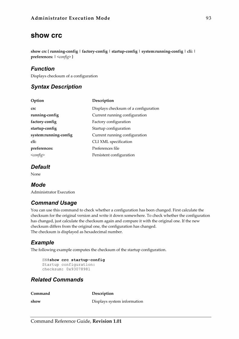
Administrator Execution Mode 93
Command Reference Guide, Revision 1.01
show crc show crc { running-config | factory-config | startup-config | system:running-config | cli: | preferences: | <config> }
Function Displays checksum of a configuration
Syntax Description Option Description
crc running-config factory-config startup-config system:running-config cli: preferences: <config>
Displays checksum of a configuration Current running configuration Factory configuration Startup configuration Current running configuration CLI XML specification Preferences file Persistent configuration
Default None
Mode Administrator Execution
Command Usage You can use this command to check whether a configuration has been changed. First calculate the checksum for the original version and write it down somewhere. To check whether the configuration has changed, just calculate the checksum again and compare it with the original one. If the new checksum differs from the original one, the configuration has changed. The checksum is displayed as hexadecimal number.
Example The following example computes the checksum of the startup configuration.
SN#show crc startup-config Startup configuration: checksum: 0x93078981
Related Commands Command Description
show Displays system information

94 Administrator Execution Mode
Command Reference Guide, Revision 1.01
show gateway h323 show gateway h323 [ <name> ] { config | status | stack-config }
Function Displays H.323 gateway information
Syntax Description Option Description
<name> config status
Name of the H.323 gateway Displays h323-gateway configuration Displays h323-gateway status
Default The value of option <name> is set to h323 by default.
Mode Administrator Execution
Command Usage Displays configuration or status information about the H.323 gateway.
Example The following example displays the H.323 gateway configuration:
SN#show gateway h323 config The next example displays the H.323 gateway status:
SN#show gateway h323 status
Related Commands None

Administrator Execution Mode 95
Command Reference Guide, Revision 1.01
show gateway isoip show gateway isoip [ <name> ] { sessions | connections } [ <detail> ]
Function Displays isoip information
Syntax Description Option Description
gateway isoip <name> sessions connections <detail>
Displays gateway information Displays isoip information Name of the ISoIP gateway Displays information about current ISoIP sessions Displays information about current ISoIP connections Detail level
Default The value of option <name> is set to isoip by default.
Mode Administrator Execution
Command Usage Displays status information about the ISoIP gateway.
Example The following example displays all currently active ISoIP sessions:
SN#show gateway isoip sessions The next example displays all currently active ISoIP connections to remote gateways:
SN#show gateway isoip connections
Related Commands None
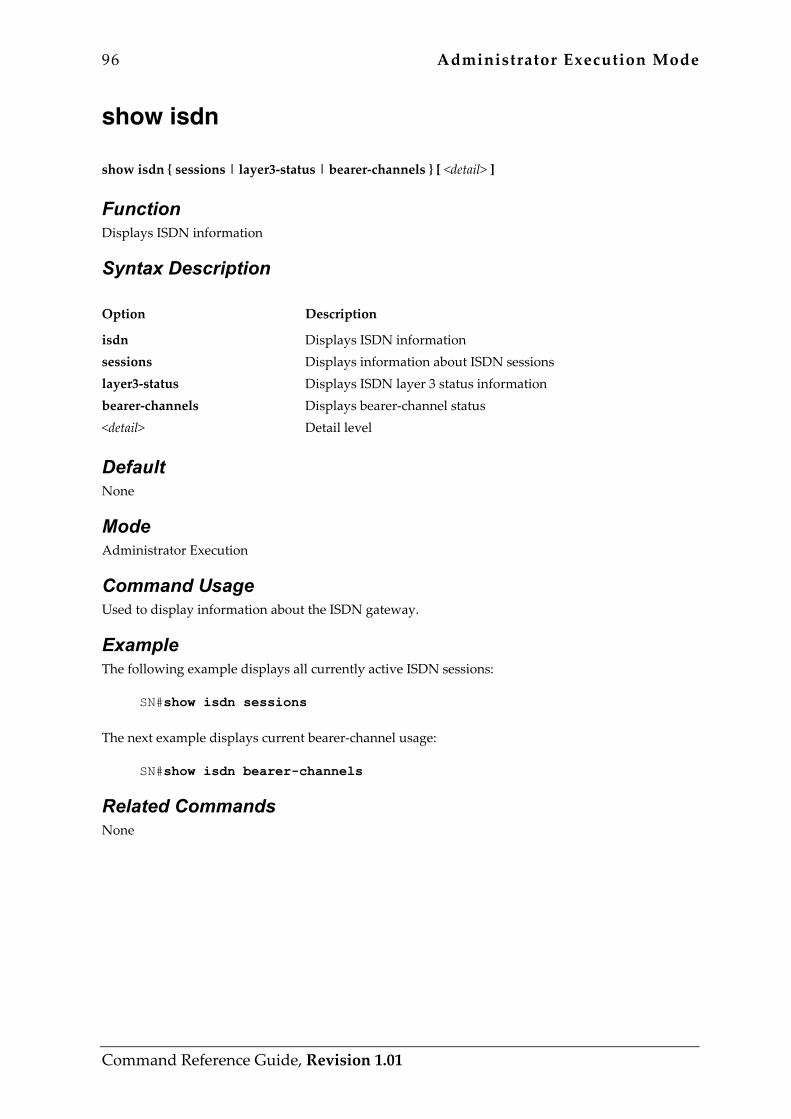
96 Administrator Execution Mode
Command Reference Guide, Revision 1.01
show isdn show isdn { sessions | layer3-status | bearer-channels } [ <detail> ]
Function Displays ISDN information
Syntax Description Option Description
isdn sessions layer3-status bearer-channels <detail>
Displays ISDN information Displays information about ISDN sessions Displays ISDN layer 3 status information Displays bearer-channel status Detail level
Default None
Mode Administrator Execution
Command Usage Used to display information about the ISDN gateway.
Example The following example displays all currently active ISDN sessions:
SN#show isdn sessions The next example displays current bearer-channel usage:
SN#show isdn bearer-channels
Related Commands None
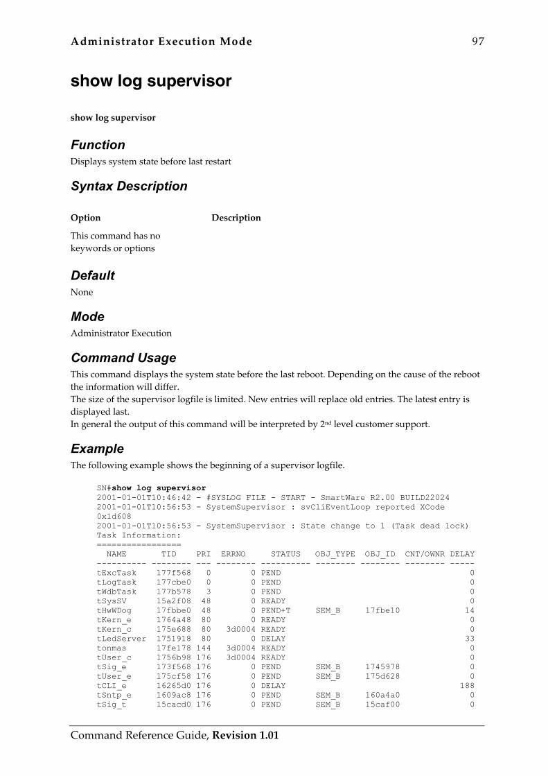
Administrator Execution Mode 97
Command Reference Guide, Revision 1.01
show log supervisor show log supervisor
Function Displays system state before last restart
Syntax Description Option Description
This command has no keywords or options
Default None
Mode Administrator Execution
Command Usage This command displays the system state before the last reboot. Depending on the cause of the reboot the information will differ. The size of the supervisor logfile is limited. New entries will replace old entries. The latest entry is displayed last. In general the output of this command will be interpreted by 2nd level customer support.
Example The following example shows the beginning of a supervisor logfile.
SN#show log supervisor 2001-01-01T10:46:42 - #SYSLOG FILE - START - SmartWare R2.00 BUILD22024 2001-01-01T10:56:53 - SystemSupervisor : svCliEventLoop reported XCode 0x1d608 2001-01-01T10:56:53 - SystemSupervisor : State change to 1 (Task dead lock) Task Information: ================= NAME TID PRI ERRNO STATUS OBJ_TYPE OBJ_ID CNT/OWNR DELAY ---------- -------- --- -------- ---------- -------- -------- -------- ----- tExcTask 177f568 0 0 PEND 0 tLogTask 177cbe0 0 0 PEND 0 tWdbTask 177b578 3 0 PEND 0 tSysSV 15a2f08 48 0 READY 0 tHwWDog 17fbbe0 48 0 PEND+T SEM_B 17fbe10 14 tKern_e 1764a48 80 0 READY 0 tKern_c 175e688 80 3d0004 READY 0 tLedServer 1751918 80 0 DELAY 33 tonmas 17fe178 144 3d0004 READY 0 tUser_c 1756b98 176 3d0004 READY 0 tSig_e 173f568 176 0 PEND SEM_B 1745978 0 tUser_e 175cf58 176 0 PEND SEM_B 175d628 0 tCLI_e 16265d0 176 0 DELAY 188 tSntp_e 1609ac8 176 0 PEND SEM_B 160a4a0 0 tSig_t 15cacd0 176 0 PEND SEM_B 15caf00 0

98 Administrator Execution Mode
Command Reference Guide, Revision 1.01
tFileXfer 155daa0 176 0 PEND SEM_B 16162e0 0 tDownLd 1559888 176 0 PEND SEM_B 1616138 0 tSig_c 172f350 176 0 PEND SEM_B 1745938 0 tEcmProd 15a3898 208 0 PEND SEM_B 155e680 0
Related Commands Command Description
show log Displays system log
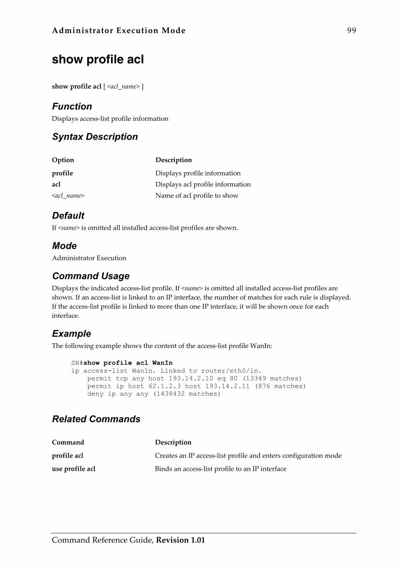
Administrator Execution Mode 99
Command Reference Guide, Revision 1.01
show profile acl show profile acl [ <acl_name> ]
Function Displays access-list profile information
Syntax Description Option Description
profile acl <acl_name>
Displays profile information Displays acl profile information Name of acl profile to show
Default If <name> is omitted all installed access-list profiles are shown.
Mode Administrator Execution
Command Usage Displays the indicated access-list profile. If <name> is omitted all installed access-list profiles are shown. If an access-list is linked to an IP interface, the number of matches for each rule is displayed. If the access-list profile is linked to more than one IP interface, it will be shown once for each interface.
Example The following example shows the content of the access-list profile WanIn:
SN#show profile acl WanIn ip access-list WanIn. Linked to router/eth0/in. permit tcp any host 193.14.2.10 eq 80 (13349 matches) permit ip host 62.1.2.3 host 193.14.2.11 (876 matches) deny ip any any (1438432 matches)
Related Commands Command Description
profile acl Creates an IP access-list profile and enters configuration mode
use profile acl Binds an access-list profile to an IP interface
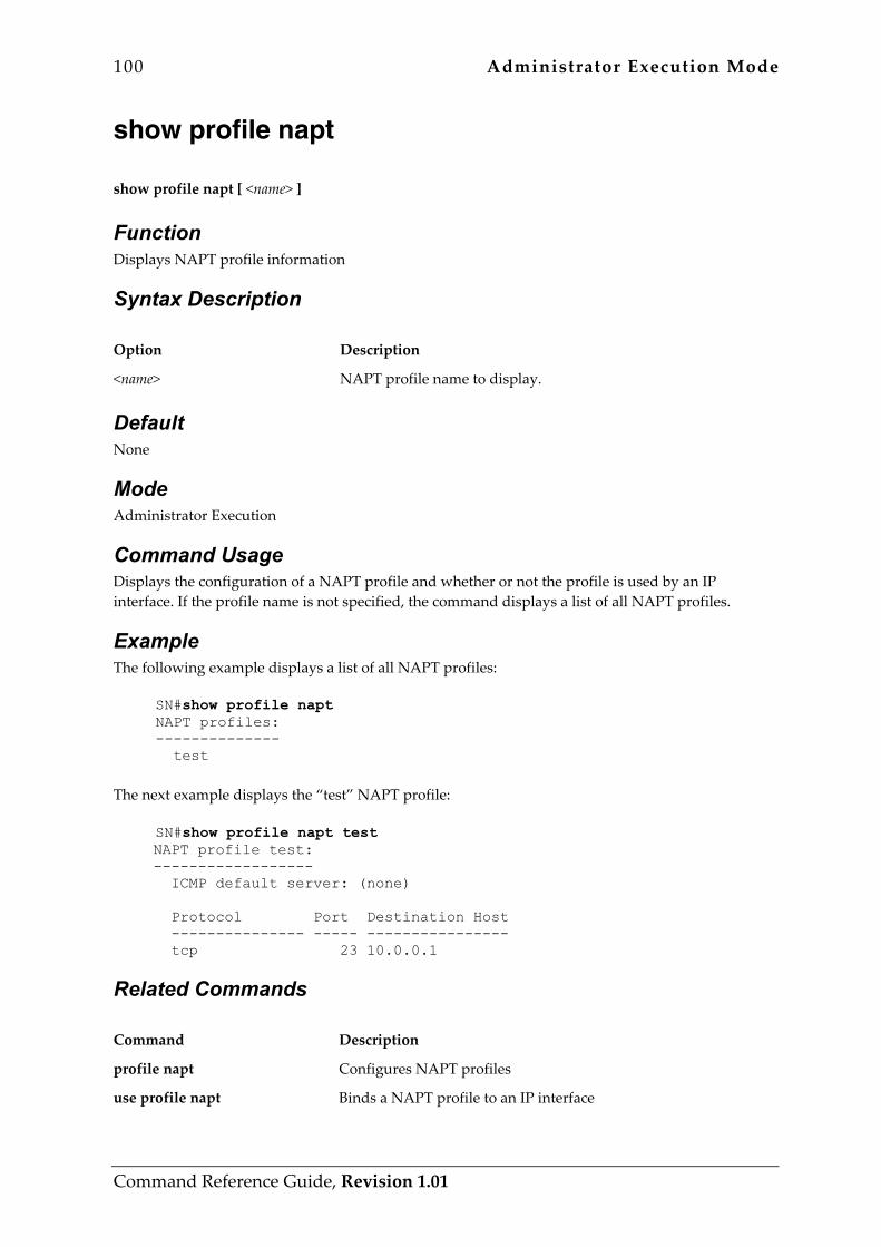
100 Administrator Execution Mode
Command Reference Guide, Revision 1.01
show profile napt show profile napt [ <name> ]
Function Displays NAPT profile information
Syntax Description Option Description
<name> NAPT profile name to display.
Default None
Mode Administrator Execution
Command Usage Displays the configuration of a NAPT profile and whether or not the profile is used by an IP interface. If the profile name is not specified, the command displays a list of all NAPT profiles.
Example The following example displays a list of all NAPT profiles:
SN#show profile napt NAPT profiles: -------------- test
The next example displays the “test” NAPT profile:
SN#show profile napt test NAPT profile test: ------------------ ICMP default server: (none) Protocol Port Destination Host --------------- ----- ---------------- tcp 23 10.0.0.1
Related Commands Command Description
profile napt Configures NAPT profiles
use profile napt Binds a NAPT profile to an IP interface
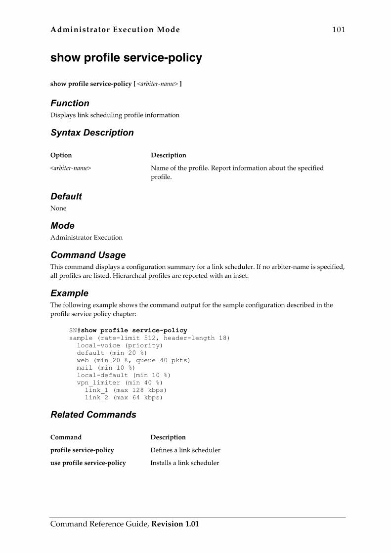
Administrator Execution Mode 101
Command Reference Guide, Revision 1.01
show profile service-policy show profile service-policy [ <arbiter-name> ]
Function Displays link scheduling profile information
Syntax Description Option Description
<arbiter-name> Name of the profile. Report information about the specified profile.
Default None
Mode Administrator Execution
Command Usage This command displays a configuration summary for a link scheduler. If no arbiter-name is specified, all profiles are listed. Hierarchcal profiles are reported with an inset.
Example The following example shows the command output for the sample configuration described in the profile service policy chapter:
SN#show profile service-policy sample (rate-limit 512, header-length 18) local-voice (priority) default (min 20 %) web (min 20 %, queue 40 pkts) mail (min 10 %) local-default (min 10 %) vpn_limiter (min 40 %) link_1 (max 128 kbps) link_2 (max 64 kbps)
Related Commands Command Description
profile service-policy Defines a link scheduler
use profile service-policy Installs a link scheduler
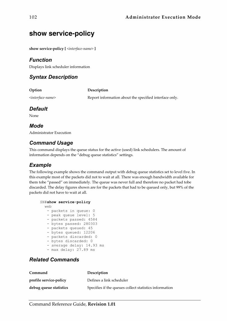
102 Administrator Execution Mode
Command Reference Guide, Revision 1.01
show service-policy show service-policy [ <interface-name> ]
Function Displays link scheduler information
Syntax Description Option Description
<interface-name> Report information about the specified interface only.
Default None
Mode Administrator Execution
Command Usage This command displays the queue status for the active (used) link schedulers. The amount of information depends on the “debug queue statistics” settings.
Example The following example shows the command output with debug queue statistics set to level five. In this example most of the packets did not to wait at all. There was enough bandwidth available for them tobe “passed” on immediately. The queue was never full and therefore no packet had tobe discarded. The delay figures shown are for the packets that had to be queued only, but 99% of the packets did not have to wait at all.
SN#show service-policy web - packets in queue: 0 - peak queue level: 5 - packets passed: 4584 - bytes passed: 280303 - packets queued: 45 - bytes queued: 12206 - packets discarded: 0 - bytes discarded: 0 - average delay: 14.93 ms - max delay: 27.89 ms
Related Commands Command Description
profile service-policy Defines a link scheduler
debug queue statistics Specifies if the queues collect statistics information

Administrator Execution Mode 103
Command Reference Guide, Revision 1.01
show session-control show session-control [ <name> ] { subsystems | sessions } [ <detail> ]
Function Displays session-control information
Syntax Description Option Description
session-control <name> subsystems sessions <detail>
Displays session-control information Name of the CS context Displays information about registered subsystems Displays information about session-control sessions Detail level
Default The value of option <name> is set to switch by default.
Mode Administrator Execution
Command Usage Displays information about all subsystems currently registered at the session-control and about currently active voice sessions.
Example The following example displays all currently active voice sessions:
SN#show session-control sessions The next example shows all registered subsystems:
SN#show session-control subsystems
Related Commands None

104 Administrator Execution Mode
Command Reference Guide, Revision 1.01
show snmp show snmp
Function Displays system information related to the configuration or use of the Simple Network Management Protocol (SNMP).
Syntax Description Option Description
This command has no keywords or options
Default None
Mode Administrator Execution
Command Usage This command is used to display system information related to the configuration or use of the Simple Network Management Protocol (SNMP).
Example The following example shows the usage of this command:
SN#show snmp SNMP Information: hostname : SN location : Building 2, 3rd Floor, Room-C contact : Hotline 1-800-800-800 Hosts: 172.16.36.74 security-name public Targets: 172.16.36.74 security-name public Communities: public access-right rw
Related Commands Command Description
snmp community Defines an SNMP community and its access rights

Administrator Execution Mode 105
Command Reference Guide, Revision 1.01
snmp host Defines the access of a host to the MIB objects.
snmp target Defines an SNMP notification (trap) receiver
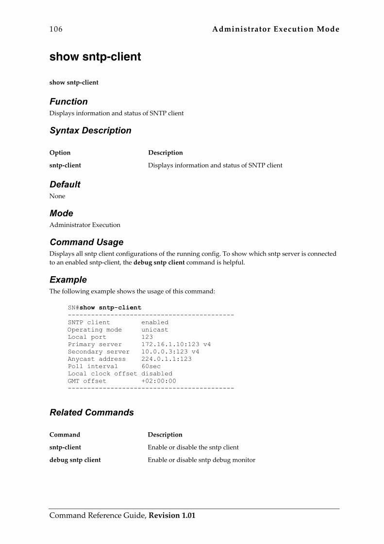
106 Administrator Execution Mode
Command Reference Guide, Revision 1.01
show sntp-client show sntp-client
Function Displays information and status of SNTP client
Syntax Description Option Description
sntp-client Displays information and status of SNTP client
Default None
Mode Administrator Execution
Command Usage Displays all sntp client configurations of the running config. To show which sntp server is connected to an enabled sntp-client, the debug sntp client command is helpful.
Example The following example shows the usage of this command:
SN#show sntp-client ------------------------------------------- SNTP client enabled Operating mode unicast Local port 123 Primary server 172.16.1.10:123 v4 Secondary server 10.0.0.3:123 v4 Anycast address 224.0.1.1:123 Poll interval 60sec Local clock offset disabled GMT offset +02:00:00 -------------------------------------------
Related Commands Command Description
sntp-client Enable or disable the sntp client
debug sntp client Enable or disable sntp debug monitor
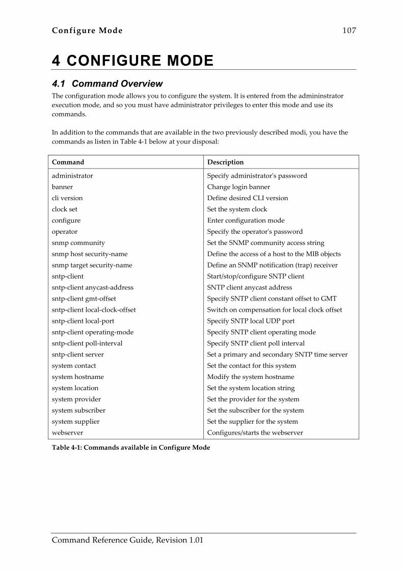
Configure Mode 107
Command Reference Guide, Revision 1.01
4 CONFIGURE MODE 4.1 Command Overview The configuration mode allows you to configure the system. It is entered from the admininstrator execution mode, and so you must have administrator privileges to enter this mode and use its commands. In addition to the commands that are available in the two previously described modi, you have the commands as listen in Table 4-1 below at your disposal:
Command Description
administrator banner cli version clock set configure operator snmp community snmp host security-name snmp target security-name sntp-client sntp-client anycast-address sntp-client gmt-offset sntp-client local-clock-offset sntp-client local-port sntp-client operating-mode sntp-client poll-interval sntp-client server system contact system hostname system location system provider system subscriber system supplier webserver
Specify administrator's password Change login banner Define desired CLI version Set the system clock Enter configuration mode Specify the operator's password Set the SNMP community access string Define the access of a host to the MIB objects Define an SNMP notification (trap) receiver Start/stop/configure SNTP client SNTP client anycast address Specify SNTP client constant offset to GMT Switch on compensation for local clock offset Specify SNTP local UDP port Specify SNTP client operating mode Specify SNTP client poll interval Set a primary and secondary SNTP time server Set the contact for this system Modify the system hostname Set the system location string Set the provider for the system Set the subscriber for the system Set the supplier for the system Configures/starts the webserver
Table 4-1: Commands available in Configure Mode
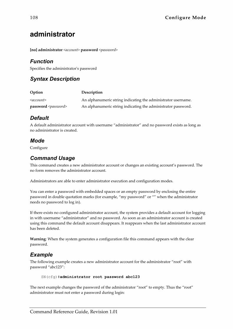
108 Configure Mode
Command Reference Guide, Revision 1.01
administrator [no] administrator <account> password <password>
Function Specifies the administrator's password
Syntax Description Option Description
<account> password <password>
An alphanumeric string indicating the administrator username. An alphanumeric string indicating the administrator password.
Default A default administrator account with username “administrator” and no password exists as long as no administrator is created.
Mode Configure
Command Usage This command creates a new administrator account or changes an existing account’s password. The no form removes the administrator account. Administrators are able to enter administrator execution and configuration modes. You can enter a password with embedded spaces or an empty password by enclosing the entire password in double quotation marks (for example, “my password” or “” when the administrator needs no password to log in). If there exists no configured administrator account, the system provides a default account for logging in with username “administrator” and no password. As soon as an administrator account is created using this command the default account disappears. It reappears when the last administrator account has been deleted. Warning: When the system generates a configuration file this command appears with the clear password.
Example The following example creates a new administrator account for the administrator “root” with password “abc123”:
SN(cfg)#administrator root password abc123 The next example changes the password of the administrator “root” to empty. Thus the “root” administrator must not enter a password during login:

Configure Mode 109
Command Reference Guide, Revision 1.01
SN(cfg)#administrator root password “”
The next example removes the account of the administrator “root”.
SN(cfg)#no administrator root
Related Commands Command Description
operator Configures operator accounts
show accounts Displays administrator and operator accounts
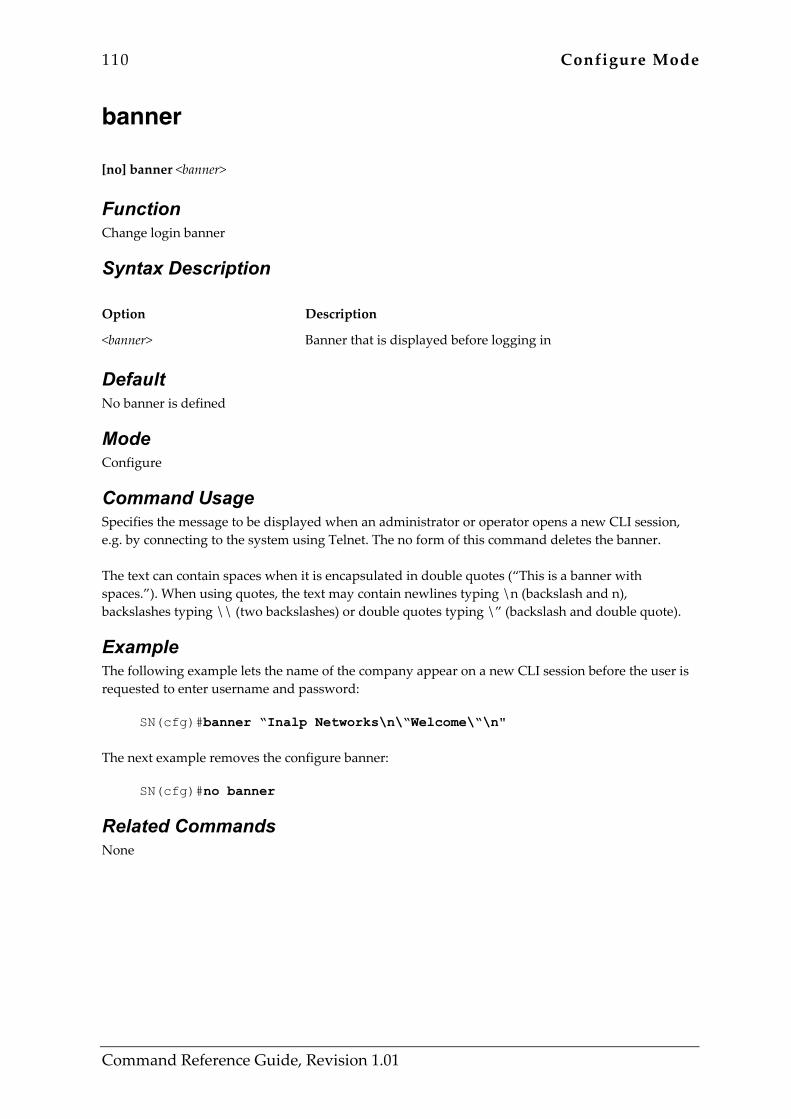
110 Configure Mode
Command Reference Guide, Revision 1.01
banner [no] banner <banner>
Function Change login banner
Syntax Description Option Description
<banner> Banner that is displayed before logging in
Default No banner is defined
Mode Configure
Command Usage Specifies the message to be displayed when an administrator or operator opens a new CLI session, e.g. by connecting to the system using Telnet. The no form of this command deletes the banner. The text can contain spaces when it is encapsulated in double quotes (“This is a banner with spaces.”). When using quotes, the text may contain newlines typing \n (backslash and n), backslashes typing \\ (two backslashes) or double quotes typing \” (backslash and double quote).
Example The following example lets the name of the company appear on a new CLI session before the user is requested to enter username and password:
SN(cfg)#banner “Inalp Networks\n\“Welcome\“\n" The next example removes the configure banner:
SN(cfg)#no banner
Related Commands None
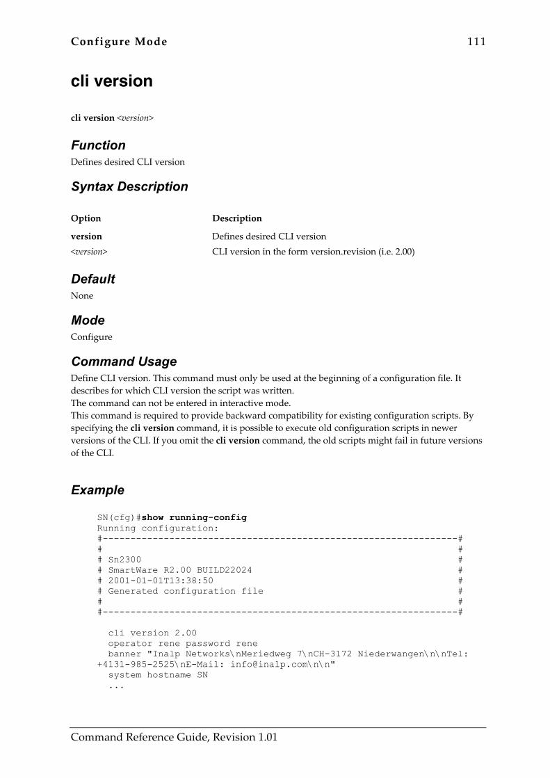
Configure Mode 111
Command Reference Guide, Revision 1.01
cli version cli version <version>
Function Defines desired CLI version
Syntax Description Option Description
version <version>
Defines desired CLI version CLI version in the form version.revision (i.e. 2.00)
Default None
Mode Configure
Command Usage Define CLI version. This command must only be used at the beginning of a configuration file. It describes for which CLI version the script was written. The command can not be entered in interactive mode. This command is required to provide backward compatibility for existing configuration scripts. By specifying the cli version command, it is possible to execute old configuration scripts in newer versions of the CLI. If you omit the cli version command, the old scripts might fail in future versions of the CLI.
Example
SN(cfg)#show running-config Running configuration: #----------------------------------------------------------------# # # # Sn2300 # # SmartWare R2.00 BUILD22024 # # 2001-01-01T13:38:50 # # Generated configuration file # # # #----------------------------------------------------------------# cli version 2.00 operator rene password rene banner "Inalp Networks\nMeriedweg 7\nCH-3172 Niederwangen\n\nTel: +4131-985-2525\nE-Mail: [email protected]\n\n" system hostname SN ...

112 Configure Mode
Command Reference Guide, Revision 1.01
Related Commands Command Description
show cli version Show CLI version

Configure Mode 113
Command Reference Guide, Revision 1.01
clock set clock set <time>
Function Sets the system clock
Syntax Description Option Description
<time> Date and time to set of the form yyyy-mm-ddThh:mm:ss
Default None
Mode Configure
Command Usage Use this command to set the date and time of the system. You must always specify date and time of the form yyyy-mm-ddThh:mm:ss, where yyyy is the year in four digits, mm the month in two digits and dd the day of the month in two digits, hh is the hour in two digits, mm the minute in two digits and ss the second in two digits. You always have to specify the full number of digits. Warning: Don’t enter this command when the SNTP client is enables. The SNTP client periodically sets date and time and overwrites a time configured using this command.
Example The following examples sets the clock to Thursday, May the 2nd 2002 at 12:00:00:
SN(cfg)#clock set 2002-05-02T12:00:00
Related Commands Command Description
show clock Displays the current system date and time
114 Configure Mode
Command Reference Guide, Revision 1.01
configure configure
Function Enters configuration mode
Syntax Description Option Description
This command has no keywords or options
Default None
Mode Configure
Command Usage Enters configuration mode. After you enter the configure command, the system prompt changes from nodename# to nodename(config)#, indicating that you are in configuration mode. To avoid consistency problems, only one session may be in configuration mode or a configuration sub mode. If another CLI session already is in configuration mode, the invocation of this command expects a confirmation. To leave configuration mode and return to the administrator execution mode, use the end command.
Example The following examples changes from administrator execution mode to configuration mode:
SN#configure SN(cfg)#
The next example shows that you must confirm entering the configuration mode if another session already configures the system:
SN#configure Another session already configures the system. Multiple configuration sessions may cause conflicts. Press 'yes' to enter configuration mode, 'no' to cancel : yes SN(cfg)#
Related Commands Command Description
end Exits configuration mode and returns to administrator execution mode

Configure Mode 115
Command Reference Guide, Revision 1.01
116 Configure Mode
Command Reference Guide, Revision 1.01
operator [no] operator <account> password <password>
Function Specifies operator's password
Syntax Description Option Description
<account> password <password>
An alphanumeric string indicating the operator username. An alphanumeric string indicating the operator password.
Default None
Mode Configure
Command Usage This command creates a new operator account or changes an existing operator’s password. The no form removes the operator account. Operators are not able to enter administrator execution or configuration modes. You can enter a password with embedded spaces or an empty password by enclosing the entire password in double quotation marks (for example, “my password” or “” when the operator needs no password to log in). Warning: When the system generates a configuration file this command appears with the clear password.
Example The following example create a new operator account for the operator john with password “123456”:
SN(cfg)#operator john password 123456 The next example changes the password of the operator “john” to empty. Thus John must not enter a password during login:
SN(cfg)#operator john password “” The next example removes the account for the operator “john”:
SN(cfg)#no operator john

Configure Mode 117
Command Reference Guide, Revision 1.01
Related Commands Command Description
administrator Configures administrator accounts
show accounts Displays administrator and operator accounts

118 Configure Mode
Command Reference Guide, Revision 1.01
snmp community [no] snmp community <community> { ro|rw }
Function Sets the community access string used to permit access to the SNMP protocol and MIB objects on the system
Syntax Description Option Description
<community> ro rw
SNMP community string Access-right read-only Access-right read-write
Default Community public with read-only access to the MIB objects.
Mode Configure
Command Usage Use the no form to remove a community string.
Example The following command defines the community public to have read-only access to the MIB objects.
SN(cfg)#snmp community public ro
Related Commands Command Description
snmp host Defines the access of a host to the MIB objects.
snmp target Defines an SNMP notification (trap) receiver
show snmp Display information about SNMP
Configure Mode 119
Command Reference Guide, Revision 1.01
snmp host security-name [no] snmp host <ip-address> security-name <community>
Function Defines the access of a host to the MIB objects
Syntax Description Option Description
<ip-address> security-name <community>
IP address of the host The community of the host Community string
Default All hosts have access to the MIB objects of the system as defined by the security-name public.
Mode Configure
Command Usage The community given as security-name must be configured before using this command. Use the no form to remove a host from a community.
Example The following commands define a community private with read-write access and apply the security rights of that community to the host with the IP address 172.16.1.11. The host with the IP address 172.16.1.11 therefore has access to the MIB objects of the system as defined in the community private.
SN(cfg)#snmp community private rw SN(cfg)#snmp host 172.16.1.11 security-name private
Related Commands Command Description
snmp community Defines an SNMP community and its access rights
snmp target Defines an SNMP notification (trap) receiver
show snmp Displays information about SNMP
120 Configure Mode
Command Reference Guide, Revision 1.01
snmp target security-name [no] snmp target <ip-address> security-name <community>
Function Defines an SNMP notification (trap) receiver
Syntax Description Option Description
target <ip-address> security-name <community>
Configure a target that will receive SNMP traps IP address of the target The community of the target Community string
Default None
Mode Configure
Command Usage The community given as security-name must be configured before using this command. Use the no form to remove a notification receiver.
Example The following command adds the target with the IP address 172.16.1.11 to the receivers of SNMP notifications (traps).
SN(cfg)#snmp target 172.16.1.11 security-name public
Related Commands Command Description
snmp community Defines an SNMP community and its access rights
snmp host Defines the access of a host to the MIB objects.
show snmp Displays information about SNMP
Configure Mode 121
Command Reference Guide, Revision 1.01
sntp-client [no] sntp-client
Function Start, stop or configure SNTP client
Syntax Description Option Description
This command has no keywords or options
Default None
Mode Configure
Command Usage This command is used to enable (disable by invertion) the sntp client. After the execution of the non-inverted command, the sntp client sends immediately a sntp request (except in multicast mode), even the sntp client was already running. This is used to send a request, without waiting for the specified poll interval.
Example The following examples shows the usage of this command:
SN(cfg)#sntp-client SN(cfg)#no sntp-client
Related Commands Command Description
show sntp client Displays sntp client configuration
122 Configure Mode
Command Reference Guide, Revision 1.01
sntp-client anycast-address sntp-client anycast-address <ip_anycast-address> [port <sntp_port> ]
Function SNTP client anycast address
Syntax Description Option Description
anycast-address <ip_anycast-address> port <sntp_port>
SNTP client anycast address SNTP client anycast address Set the server port SNTP server port number
Default None
Mode Configure
Command Usage The anycast address must be a valid multicast address. The RFC specifies the address 224.0.1.1 as the default multicast address.
Example The following example shows how to configure the default anycast address:
SN(cfg)#sntp-client anycast-address 224.0.1.1 port 123
Related Commands None
Configure Mode 123
Command Reference Guide, Revision 1.01
sntp-client gmt-offset sntp-client gmt-offset { + | - } <time_gmtoffset>
Function Specify SNTP client constant offset to GMT
Syntax Description Option Description
+ - <time_gmtoffset>
positive time offset from GMT negative time offset from GMT time offset in format hh:mm:ss from GMT
Default None
Mode Configure
Command Usage This command is used to adjust the received time to the local timezone.
Example The following example shows how to set the GMT offset to +2 hours:
SN(cfg)#sntp-client gmt-offset + 02:00:00
Related Commands Command Description
sntp-client local-clock-offset Switch on compensation for local clock offset
124 Configure Mode
Command Reference Guide, Revision 1.01
sntp-client local-clock-offset [no] sntp-client local-clock-offset
Function Switch on compensation for local clock offset
Syntax Description Option Description
local-clock-offset Switch on compensation for local clock offset
Default None
Mode Configure
Command Usage If enabled the local-clock-offset is added to the received timestamp. The local-clock-offset is calculated as the average of packet-transmission differences.
Example The following example shows how to use this command:
SN(cfg)#sntp-client local-clock-offset SN(cfg)#no sntp-client local-clock-offset
Related Commands Command Description
sntp-client gmt-offset { + | - } <time_gmtoffset> Specify SNTP client constant offset to GMT
Configure Mode 125
Command Reference Guide, Revision 1.01
sntp-client local-port sntp-client local-port <sntp_port>
Function Specify SNTP local UDP port
Syntax Description Option Description
local-port <sntp_port>
Specify SNTP local UDP port SNTP local UDP port number
Default None
Mode Configure
Command Usage To force the source port of a SNTP message, a port value in the range from 1 to 65535 can be entered. The value 0 means that the router will choose any free port.
Example The following example sets the sntp clients source address to 123 (default SNTP port):
SN(cfg)#sntp-client local-port 123
Related Commands None
126 Configure Mode
Command Reference Guide, Revision 1.01
sntp-client operating-mode sntp-client operating-mode { unicast | multicast | anycast }
Function Specify SNTP client operating mode
Syntax Description Option Description
unicast multicast anycast
SNTP client unicast operation SNTP client multicast operation SNTP client anycast operation
Default None
Mode Configure
Command Usage A SNTP client can operate in multicast mode, unicast mode or anycast mode:
• In unicast mode (point to point), the client sends a request to a designated server at its unicast address and expects a reply from which it can determine the time and, optionally, the roundtrip delay and local clock offset relative to the server.
• In anycast mode (multipoint to point), the client sends a request to a designated local broadcast or multicast group address and expects a reply from one or more anycast servers.
• In multicast mode (point to multipoint), the client sends no request and waits for a broadcast from a designated multicast server.
Example The following example configures the SNTP client operating mode to unicast operation
SN(cfg)#sntp-client operating-mode unicast The next example configures the SNTP client operating mode to anycast operation
SN(cfg)#sntp-client operating-mode anycast The last example configures the SNTP client operating mode to multicast operation
SN(cfg)#sntp-client operating-mode multicast
Related Commands None
Configure Mode 127
Command Reference Guide, Revision 1.01
sntp-client poll-interval sntp-client poll-interval <number_pollinterval>
Function Specify SNTP client poll interval
Syntax Description Option Description
poll-interval <number_pollinterval>
Specify SNTP client poll interval SNTP client poll interval
Default The default value for option <number_pollinterval> is 60 seconds.
Mode Configure
Command Usage Specifies the seconds between each SNTP client request in unicast or anycast mode. This SNTP client poll interval can be defined to be within in the range from 1 to 4’294’967’295.
Example In the following example the SNTP client poll interval is set to 30 seconds.
SN(cfg)#sntp-client poll-interval 30
Related Commands None
128 Configure Mode
Command Reference Guide, Revision 1.01
sntp-client server sntp-client server { primary | secondary } <server_address> [ port <sntp_port> ] [version <version_number> ]
Function Set a primary and secondary SNTP time server.
Syntax Description Option Description
primary secondary <server_address> port <sntp_port> version <version_number>
Primary time server Secondary time server SNTP server IP address Set the server port SNTP server port number Specify the SNTP protocol version Version number of SNTP protocol
Default None
Mode Configure
Command Usage This command is used to set a primary and secondary SNTP time server. It is recommended to set both the primary and secondary server, that in case of unavailablility of a SNTP time server a backup time server can be used.
Example In the following example an internal SNTP time server (172.16.1.10) is selected as primary and utcnist.colorado.edu (128.138.140.44) as secondary SNTP time server.
SN(cfg)#sntp-client server primary 172.16.1.10 SN(cfg)#sntp-client server secondary 128.138.140.44
Related Commands None
Configure Mode 129
Command Reference Guide, Revision 1.01
system contact system contact <string>
Function Set the contact information for this SmartNode
Syntax Description Option Description
contact <string>
Set the contact for this system Text that describes the contact for this system
Default The system contact is empty.
Mode Configure
Command Usage This command is used to configure the information available via the sysContact MIB-II object. Use system contact “” to configure an empty system contact.
Example The following example shows how to set the system contact information:
SN(cfg)#system contact “Hotline 1-800-800-800”
Related Commands Command Description
show snmp Displays information about SNMP
system hostname Modifies the host name of the device
system location Sets the system location string
130 Configure Mode
Command Reference Guide, Revision 1.01
system hostname system hostname <string>
Function Modifies the system hostname
Syntax Description Option Description
hostname <string>
Set the system hostname String representing the system hostname
Default The system hostname is empty.
Mode Configure
Command Usage This command is used to configure the host name of the device. Use system hostname “” to configure an empty name.
Example The following example shows how to set the system hostname to SmartNode:
SN(cfg)#system hostname SmartNode SmartNode(cfg)#
Related Commands Command Description
show snmp Displays information about SNMP
system contact Sets the contact string for this system
system location Sets the system location string
Configure Mode 131
Command Reference Guide, Revision 1.01
system location system location <string>
Function Sets the system location string
Syntax Description Option Description
location <string>
Describe system location Text that describes the system location
Default None
Mode Configure
Command Usage The command system location is used to configure the information available via the sysLocation MIB-II object. Use system location “” to configure an empty location string.
Example The following example shows how to set the system location information:
SN(cfg)#system location “Building 2, Floor 3, Room C”
Related Commands Command Description
show snmp Displays information about SNMP
system contact Sets the contact string for this system
system hostname Modifies the host name of the device
132 Configure Mode
Command Reference Guide, Revision 1.01
system provider system provider <string>
Function Set the provider for the system
Syntax Description Option Description
provider <string>
Set the provider for the system Text that describes the provider for this system
Default None
Mode Configure
Command Usage To set the system provider for later access via SNMP use the command system provider. The provider name is the following SNMP object: .iso.org.dod.internet.private.enterprises.inalp.temporary.smartnode.sysinfo.provider
For an extensive explanation on how to use SNMP on a SmartNode, refer to Chapter 28, "SNMP Configuration", in the Software Configuration Guide for SmartWare, Release 2.00. Warning: The maximum string length is 255 character.
Example The following examples set the system provider to Pink Telecom Solutions:
SN(cfg)#system provider “Pink Telecom Solutions” The next example deletes the system provider:
SN(cfg)#system provider “”
Related Commands Command Description
system location Sets the system location string
show version Display version information

Configure Mode 133
Command Reference Guide, Revision 1.01
system subscriber system subscriber <string>
Function Set the subscriber for the system
Syntax Description Option Description
subscriber <string>
Set the subscriber for the system Text that describes the subscriber for this system
Default None
Mode Configure
Command Usage To set the system subscriber for later access via SNMP use the command system subscriber. The subscriber name is the following SNMP object: .iso.org.dod.internet.private.enterprises.inalp.temporary.smartnode.sysinfo.subscriber
For an extensive explanation on how to use SNMP on a SmartNode, refer to Chapter 28, "SNMP Configuration", in the Software Configuration Guide for SmartWare, Release 2.00. Warning: The maximum string length is 255 character.
Example The following examples set the system subscriber to MegaSoft Inc. :
SN(cfg)#system subscriber “MegaSoft Inc.” The next example deletes the system subscriber:
SN(cfg)#system subscriber “”
Related Commands Command Description
system provider Set the provider for the system
system contact Set the contact for this system
show version Display version information
134 Configure Mode
Command Reference Guide, Revision 1.01
system supplier system supplier <string>
Function Set the supplier for the system
Syntax Description Option Description
supplier <string>
Set the supplier for the system Text that describes the supplier for this system
Default None
Mode Configure
Command Usage To set the system suppliere for later access via SNMP use the command system supplier. The supplier name is the following SNMP object: .iso.org.dod.internet.private.enterprises.inalp.temporary.smartnode.sysinfo.supplier
For an extensive explanation on how to use SNMP on a SmartNode, refer to Chapter 28, "SNMP Configuration", in the Software Configuration Guide for SmartWare, Release 2.00. Warning: The maximum string length is 255 character.
Example The following examples set the system supplierer to Inalp Netwroks Inc. :
SN(cfg)#system supplier “Inalp Netwroks Inc.” The next example deletes the system supplier:
SN(cfg)#system supplier “”
Related Commands Command Description
system hostname Modifies the system hostname
system subscriber Set the subscriber for the system
show version Display version information
Configure Mode 135
Command Reference Guide, Revision 1.01
webserver [no] webserver [ port <port> ] [ lang { en | de } ]
Function Starts the webserver or configures the webserver language and the listening port.
Syntax Description Option Description
port <port> lang en de
Sets the listening port Listening port number Sets the language English Deutsch
Default None
Mode Configure
Command Usage SmartNode includes an embedded web server, which can be used together with a customer-specific Java applet that must be downloaded into the persistent memory region of your SmartNode. Applets are similar to applications but they do not run as standalones. Instead, applets adhere to a set of conventions that lets them run within a Java-compatible browser. With a Java applet, custom-specific configuration tasks of SmartWare are possible using a browser instead of accessing the SmartWare CLI via Telnet or the serial console. Warning: Without a Java applet the value of the embedded web server is limited. Contact Inalp Networks for any questions about custom designed Java configuration tools for SmartWare.
Example The following example shows how to set the webserver language and the listening port of your device, if you start from the configuration mode.
SN(cfg)#webserver lang en SN(cfg)#webserver port 80
Related Commands None

System Mode 136
Command Reference Guide, Revision 1.01
5 SYSTEM MODE 5.1 Command Overview This chapter describes the commands that are available in system mode. The system mode is used to set some basic system settings. The commands that are available in this mode are listed in Table 5-1 below:
Command Description
bypass-mode clock-source local-inband-tones synchronize-to-isdn-time system
Enable or disable ISDN bypass mode Select clock-source for ISDN circuits Force localy generated inband-tones Set the system clock to the received ISDN time Enter system configuration mode
Table 5-1: Commands available in System Mode

System Mode 137
Command Reference Guide, Revision 1.01
bypass-mode [no] bypass-mode
Function Enable or disable ISDN bypass mode
Syntax Description Option Description
This command has no keywords or options
Default No bypass-mode
Mode System
Command Usage If the system supports an ISDN bypass between two or more ISDN ports in case of power loss, this command enables the bypass manually. Warning: If calls are active on the ports, which are bypassed, when issuing this command, the calls will be dropped.
Example The following example enables the bypass:
SN(sys)#bypass-mode The next example disables the bypass:
SN(sys)#no bypass-mode
Related Commands None
138 System Mode
Command Reference Guide, Revision 1.01
clock-source clock-source { internal | ( <slot> <port> ) }
Function Select clock-source for ISDN circuits
Syntax Description Option Description
internal <slot> <port>
Use internal clock reference ISDN slot number ISDN port number
Default None
Mode System
Command Usage The command defines the clock-source to be used for all internal PSTN/ISDN circuits. This clock is also used as the reference for all ISDN ports, which play a layer 1 master role and therefore provide a reference clock to the remote side. Warning: If this command is not configured properly, the bit-error-rate on the ISDN links will be very high.
Example The following example shows how to use the interal clock-generator as clock-source:
SN(sys)#clock-source internal The next example shows how to use the clock recovered from ISDN port 3 in slot 2 for all ISDN circuits:
SN(sys)#clock-source 2 3
Related Commands None

System Mode 139
Command Reference Guide, Revision 1.01
local-inband-tones [no] local-inband-tones
Function Force localy generated inband-tones
Syntax Description Option Description
This command has no keywords or options
Default No local-inband-tones
Mode System
Command Usage The command is used to force local-generation of dial-, ringback- and busy-tones in all cases where it is supported. If this option is not enabled, the system will only generate in-band tones in cases where no voice data is received from the remote side. If voice data is received from the remote side, it is expected to already contain the correct in-band tones.
Example The following example shows how to enable local in-band tone generation:
SN(sys)#local-inband-tones The next example shows how to disable local in-band tone generation:
SN(sys)#no local-inband-tones
Related Commands None
140 System Mode
Command Reference Guide, Revision 1.01
synchronize-to-isdn-time [no] synchronize-to-isdn-time
Function Set the system clock to the received ISDN time
Syntax Description Option Description
This command has no keywords or options
Default No synchronize-to-isdn-time
Mode System
Command Usage Used to enable adjustment of the internal real-time-clock to the time received in Q.931 signalling messages, which pass through the session-control. Warning: If Q.931 signalling messages with timestamps from different timezones are processed within the system, the real-time-clock will switch back and forth between these different timezones. Therefore only use this feature, if you are sure, that only one reliable source proviedes time information in the Q.931 signaling.
Example The following example enables real-time-clock synchronization:
SN(sys)#synchronize-to-isdn-time The next example disables real-time-clock synchronization:
SN(sys)#no synchronize-to-isdn-time
Related Commands None

System Mode 141
Command Reference Guide, Revision 1.01
system system
Function Enter the system configuration mode
Syntax Description Option Description
This command has no keywords or options
Default None
Mode System
Command Usage The system mode is used to set some basic system settings.
Example The following example shows how the system command is used to switch to the system mode:
SN(cfg)#system SN(sys)#
Related Commands None

IC Voice Mode 142
Command Reference Guide, Revision 1.01
6 IC VOICE MODE 6.1 Command Overview In this mode you may configure an interface card’s voice mode. The commands that are available, in addition to those of the modi already described, are listen in Table 6-1 below:
Command Description
ic voice pcm
Enter the interface card voice mode Configure PCM settings for all DSPs on the slot
Table 6-1: Commands available in IC Voice Mode
IC Voice Mode 143
Command Reference Guide, Revision 1.01
ic voice ic voice <slot>
Function Enter the interface card voice mode.
Syntax Description Option Description
<slot> The number of the slot (interface card)
Default None
Mode IC Voice
Command Usage The ic voice command is used to enter the interface card voice mode. Specific parameters for the selected voice interface card can be set in this mode.
Example The following example enters the voice interface card configuration mode for interface card 2:
SN(sys)#ic voice 2 SN(ic voice)[2]#
Related Commands None
144 IC Voice Mode
Command Reference Guide, Revision 1.01
pcm pcm law-select { aLaw | uLaw }
Function Configure PCM settings commonly for all DSPs on the interface card.
Syntax Description Option Description
law-select aLaw uLaw
Configure the PCM law of all DSPs on the interface card Set the PCM law to A law for all DSPs on the interface card Set the PCM law to u law for all DSPs on the interface card
Default Law-select defaults to aLaw.
Mode IC Voice
Command Usage The law-select option directly influences the G.711 companding curves the DSPs apply on the PCM side. In Europe, standard is aLaw, in the United States uLaw. Both laws are supported with a rate of 64kBit/s. The command is executed immediately, and all DSPs on the interface card will reboot. A brief voice drop on all connections on that interface card may occur. Warning: Change the law paramter only if you know that all devices that are connected to the interface card use the same, known law.
Example The following example configures the DSPs to use uLaw on interface card slot 2:
SN(ic-voice)[2]#pcm law-select uLaw
Related Commands None

Profile ACL Mode 145
Command Reference Guide, Revision 1.01
7 PROFILE ACL MODE 7.1 Command Overview In this mode you may configure an access control list (ACL). The commands that are available, in addition to those of the modi already described, are listed in Table 7-1 below:
Command Description
{ permit | deny } ip { permit | deny } icmp { permit | deny } { tcp | udp | sctp } profile acl
Add an IP filter rule to the current access-list profile Add an ICMP filter rule to the current access-list profile Create an access list profile Creates an IP ACL profile and enters configuration mode
Table 7-1: Commands available in Profile ACL Mode
146 Profile ACL Mode
Command Reference Guide, Revision 1.01
{ permit | deny } ip { permit | deny } ip { <src> <src-wildcard> | any | host <src> } { <dest> <dest-wildcard> | any | host <dest> } [ cos <group> ]
Function Add an IP filter rule to the current access-list profile
Syntax Description Option Description
<src> The source address to be included in the rule. An IP address in dotted-decimal-format (e.g. 64.231.1.10).
<src-wildcard> A wildcard for the source address. Expressed in dotted-decimal format this value specifies which bits are significant for matching. One-bits in the wildcard indicate that the corresponding bits are ignored. An example for a valid wildcard is 0.0.0.255, which specifies a class C network.
any Indicates that IP traffic to or from all IP addresses is to be included in the rule.
host <src> The address of a single source host.
<dest> The destination address to be included in the rule. An IP address in dotted-decimal-format (e.g. 64.231.1.10).
<dest-wildcard> A wildcard for the destination address. See src-wildcard.
host <dest> The address of a single destination host.
cos <group> Optional. Specifies that packets matched by this rule belong to a certain Class of Service (CoS).
Default None
Mode Profile ACL
Command Usage Rules are evaluated in the order as they were entered in the access-list profile. The first match is taken and all further matches are ignored. If you place a deny ip any any rule at the top of an access-list profile, no packets will pass regardless of the other rules you defined.
Example Create a new access-list profile named WAN_Input and enter some rules.
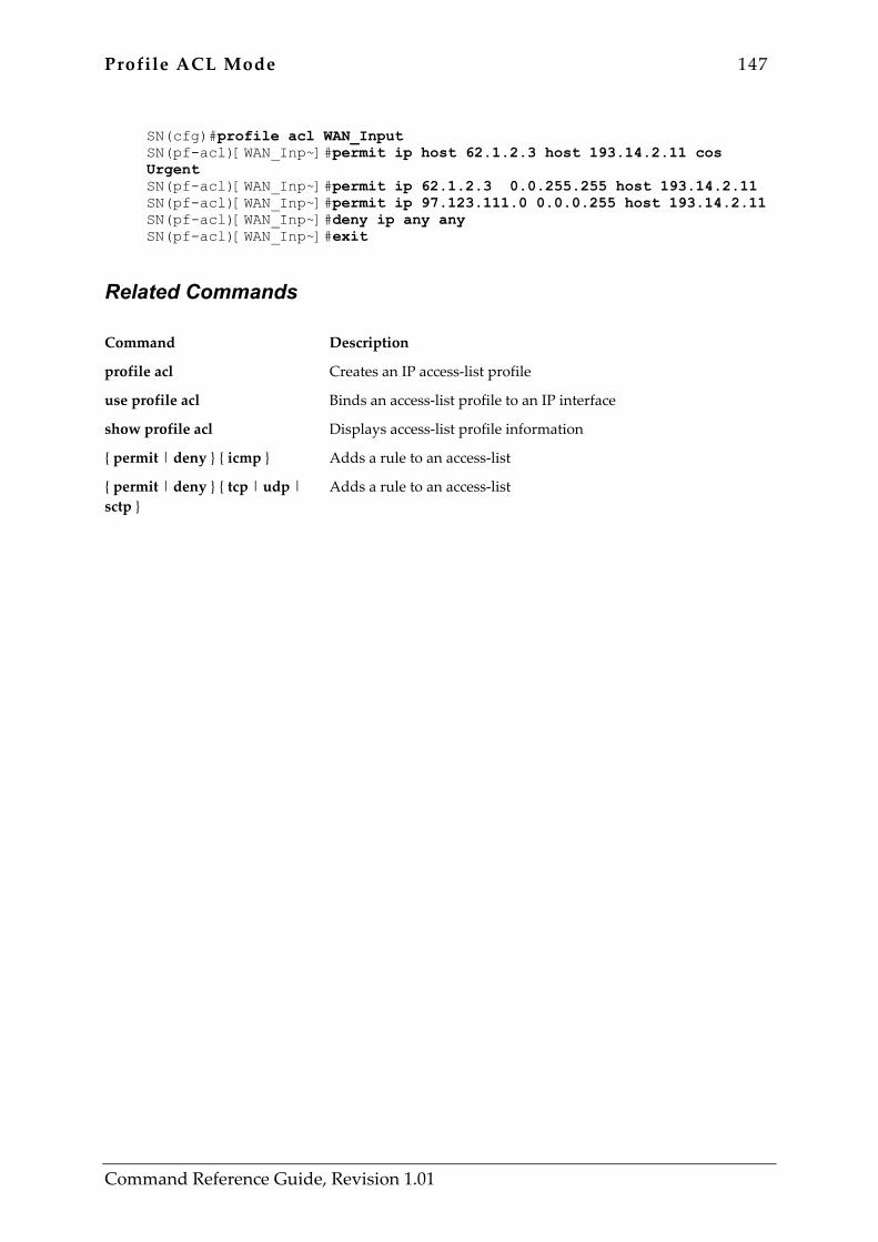
Profile ACL Mode 147
Command Reference Guide, Revision 1.01
SN(cfg)#profile acl WAN_Input SN(pf-acl)[WAN_Inp~]#permit ip host 62.1.2.3 host 193.14.2.11 cos Urgent SN(pf-acl)[WAN_Inp~]#permit ip 62.1.2.3 0.0.255.255 host 193.14.2.11 SN(pf-acl)[WAN_Inp~]#permit ip 97.123.111.0 0.0.0.255 host 193.14.2.11 SN(pf-acl)[WAN_Inp~]#deny ip any any SN(pf-acl)[WAN_Inp~]#exit
Related Commands Command Description
profile acl Creates an IP access-list profile
use profile acl Binds an access-list profile to an IP interface
show profile acl Displays access-list profile information
{ permit | deny } { icmp } Adds a rule to an access-list
{ permit | deny } { tcp | udp | sctp }
Adds a rule to an access-list
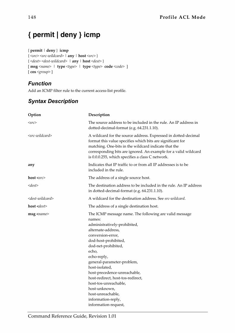
148 Profile ACL Mode
Command Reference Guide, Revision 1.01
{ permit | deny } icmp { permit | deny } icmp { <src> <src-wildcard> | any | host <src> } { <dest> <dest-wildcard> | any | host <dest> } [ msg <name> | type <type> | type <type> code <code> ] [ cos <group> ]
Function Add an ICMP filter rule to the current access-list profile.
Syntax Description Option Description
<src> The source address to be included in the rule. An IP address in dotted-decimal-format (e.g. 64.231.1.10).
<src-wildcard> A wildcard for the source address. Expressed in dotted-decimal format this value specifies which bits are significant for matching. One-bits in the wildcard indicate that the corresponding bits are ignored. An example for a valid wildcard is 0.0.0.255, which specifies a class C network.
any Indicates that IP traffic to or from all IP addresses is to be included in the rule.
host <src> The address of a single source host.
<dest> The destination address to be included in the rule. An IP address in dotted-decimal-format (e.g. 64.231.1.10).
<dest-wildcard> A wildcard for the destination address. See src-wildcard.
host <dest> The address of a single destination host.
msg <name> The ICMP message name. The following are valid message names: administratively-prohibited, alternate-address, conversion-error, dod-host-prohibited, dod-net-prohibited, echo, echo-reply, general-parameter-problem, host-isolated, host-precedence-unreachable, host-redirect, host-tos-redirect, host-tos-unreachable, host-unknown, host-unreachable, information-reply, information-request,
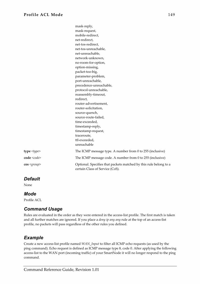
Profile ACL Mode 149
Command Reference Guide, Revision 1.01
mask-reply, mask-request, mobile-redirect, net-redirect, net-tos-redirect, net-tos-unreachable, net-unreachable, network-unknown, no-room-for-option, option-missing, packet-too-big, parameter-problem, port-unreachable, precedence-unreachable, protocol-unreachable, reassembly-timeout, redirect, router-advertisement, router-solicitation, source-quench, source-route-failed, time-exceeded, timestamp-reply, timestamp-request, traceroute, ttl-exceeded, unreachable
type <type> The ICMP message type. A number from 0 to 255 (inclusive)
code <code> The ICMP message code. A number from 0 to 255 (inclusive)
cos <group> Optional. Specifies that packets matched by this rule belong to a certain Class of Service (CoS).
Default None
Mode Profile ACL
Command Usage Rules are evaluated in the order as they were entered in the access-list profile. The first match is taken and all further matches are ignored. If you place a deny ip any any rule at the top of an access-list profile, no packets will pass regardless of the other rules you defined.
Example Create a new access-list profile named WAN_Input to filter all ICMP echo requests (as used by the ping command). Echo request is defined as ICMP message type 8, code 0. After applying the following access-list to the WAN port (incoming traffic) of your SmartNode it will no longer respond to the ping command.
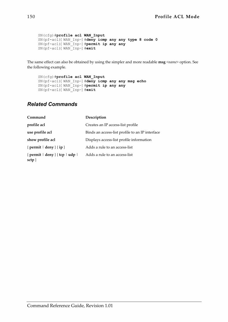
150 Profile ACL Mode
Command Reference Guide, Revision 1.01
SN(cfg)#profile acl WAN_Input SN(pf-acl)[WAN_Inp~]#deny icmp any any type 8 code 0 SN(pf-acl)[WAN_Inp~]#permit ip any any SN(pf-acl)[WAN_Inp~]#exit
The same effect can also be obtained by using the simpler and more readable msg <name> option. See the following example.
SN(cfg)#profile acl WAN_Input SN(pf-acl)[WAN_Inp~]#deny icmp any any msg echo SN(pf-acl)[WAN_Inp~]#permit ip any any SN(pf-acl)[WAN_Inp~]#exit
Related Commands Command Description
profile acl Creates an IP access-list profile
use profile acl Binds an access-list profile to an IP interface
show profile acl Displays access-list profile information
{ permit | deny } { ip } Adds a rule to an access-list
{ permit | deny } { tcp | udp | sctp }
Adds a rule to an access-list
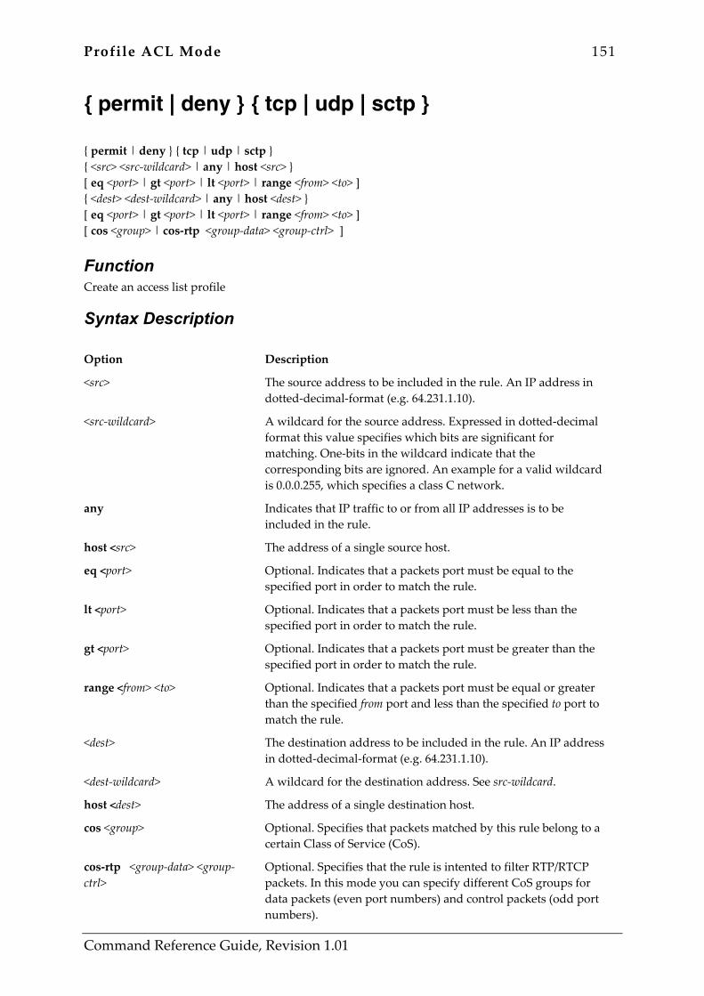
Profile ACL Mode 151
Command Reference Guide, Revision 1.01
{ permit | deny } { tcp | udp | sctp } { permit | deny } { tcp | udp | sctp } { <src> <src-wildcard> | any | host <src> } [ eq <port> | gt <port> | lt <port> | range <from> <to> ] { <dest> <dest-wildcard> | any | host <dest> } [ eq <port> | gt <port> | lt <port> | range <from> <to> ] [ cos <group> | cos-rtp <group-data> <group-ctrl> ]
Function Create an access list profile
Syntax Description Option Description
<src> The source address to be included in the rule. An IP address in dotted-decimal-format (e.g. 64.231.1.10).
<src-wildcard> A wildcard for the source address. Expressed in dotted-decimal format this value specifies which bits are significant for matching. One-bits in the wildcard indicate that the corresponding bits are ignored. An example for a valid wildcard is 0.0.0.255, which specifies a class C network.
any Indicates that IP traffic to or from all IP addresses is to be included in the rule.
host <src> The address of a single source host.
eq <port> Optional. Indicates that a packets port must be equal to the specified port in order to match the rule.
lt <port> Optional. Indicates that a packets port must be less than the specified port in order to match the rule.
gt <port> Optional. Indicates that a packets port must be greater than the specified port in order to match the rule.
range <from> <to> Optional. Indicates that a packets port must be equal or greater than the specified from port and less than the specified to port to match the rule.
<dest> The destination address to be included in the rule. An IP address in dotted-decimal-format (e.g. 64.231.1.10).
<dest-wildcard> A wildcard for the destination address. See src-wildcard.
host <dest> The address of a single destination host.
cos <group> Optional. Specifies that packets matched by this rule belong to a certain Class of Service (CoS).
cos-rtp <group-data> <group-ctrl>
Optional. Specifies that the rule is intented to filter RTP/RTCP packets. In this mode you can specify different CoS groups for data packets (even port numbers) and control packets (odd port numbers).
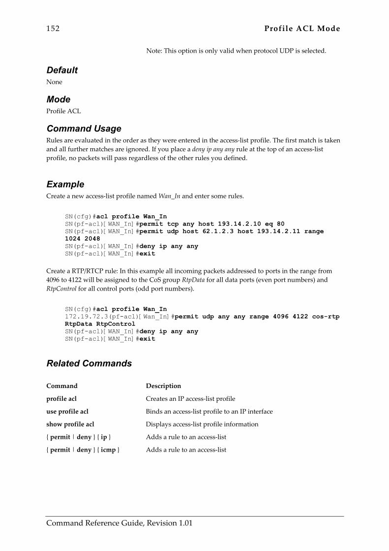
152 Profile ACL Mode
Command Reference Guide, Revision 1.01
Note: This option is only valid when protocol UDP is selected.
Default None
Mode Profile ACL
Command Usage Rules are evaluated in the order as they were entered in the access-list profile. The first match is taken and all further matches are ignored. If you place a deny ip any any rule at the top of an access-list profile, no packets will pass regardless of the other rules you defined.
Example Create a new access-list profile named Wan_In and enter some rules.
SN(cfg)#acl profile Wan_In SN(pf-acl)[WAN_In]#permit tcp any host 193.14.2.10 eq 80 SN(pf-acl)[WAN_In]#permit udp host 62.1.2.3 host 193.14.2.11 range 1024 2048 SN(pf-acl)[WAN_In]#deny ip any any SN(pf-acl)[WAN_In]#exit
Create a RTP/RTCP rule: In this example all incoming packets addressed to ports in the range from 4096 to 4122 will be assigned to the CoS group RtpData for all data ports (even port numbers) and RtpControl for all control ports (odd port numbers).
SN(cfg)#acl profile Wan_In 172.19.72.3(pf-acl)[Wan_In]#permit udp any any range 4096 4122 cos-rtp RtpData RtpControl SN(pf-acl)[WAN_In]#deny ip any any SN(pf-acl)[WAN_In]#exit
Related Commands Command Description
profile acl Creates an IP access-list profile
use profile acl Binds an access-list profile to an IP interface
show profile acl Displays access-list profile information
{ permit | deny } { ip } Adds a rule to an access-list
{ permit | deny } { icmp } Adds a rule to an access-list
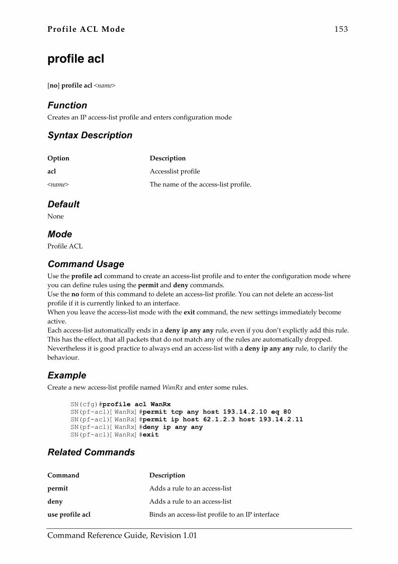
Profile ACL Mode 153
Command Reference Guide, Revision 1.01
profile acl [no] profile acl <name>
Function Creates an IP access-list profile and enters configuration mode
Syntax Description Option Description
acl Accesslist profile
<name> The name of the access-list profile.
Default None
Mode Profile ACL
Command Usage Use the profile acl command to create an access-list profile and to enter the configuration mode where you can define rules using the permit and deny commands. Use the no form of this command to delete an access-list profile. You can not delete an access-list profile if it is currently linked to an interface. When you leave the access-list mode with the exit command, the new settings immediately become active. Each access-list automatically ends in a deny ip any any rule, even if you don’t explictly add this rule. This has the effect, that all packets that do not match any of the rules are automatically dropped. Nevertheless it is good practice to always end an access-list with a deny ip any any rule, to clarify the behaviour.
Example Create a new access-list profile named WanRx and enter some rules.
SN(cfg)#profile acl WanRx SN(pf-acl)[WanRx]#permit tcp any host 193.14.2.10 eq 80 SN(pf-acl)[WanRx]#permit ip host 62.1.2.3 host 193.14.2.11 SN(pf-acl)[WanRx]#deny ip any any SN(pf-acl)[WanRx]#exit
Related Commands Command Description
permit Adds a rule to an access-list
deny Adds a rule to an access-list
use profile acl Binds an access-list profile to an IP interface

154 Profile ACL Mode
Command Reference Guide, Revision 1.01
show profile acl Displays access-list profile information

Profile Service-Policy Mode 155
Command Reference Guide, Revision 1.01
8 PROFILE SERVICE-POLICY MODE 8.1 Command Overview This chapter describes the commands used to configure the SmartWare quality of service (QoS) features. QoS in networking refers to the capability of the network to provide a better service to selected network traffic. The commands that are available, in addition to those of the modi already described, are listend in Table 8-1 below:
Command Description
mode profile service-policy rate-limit
Set arbitration scheme of selected service policy profile Enter link arbiter configuration mode Limit interface rate
Table 8-1: Commands available in Profile Service-Policy Mode
8.2 Cross Reference to Source Mode Chapter The following commands listed in Table 8-2 are described in the source mode chapter. When used in profile service-policy mode they define default values for the profile, which can be overriden in individual source modes.
Command Description
debug queue statistics queue-limit set ip dscp set ip precedence set ip tos set layer2 cos
Enable statistics for the link scheduler queues define maximum queue length for this traffic source select DiffServ marking select precedence marking define tos value select Class-Of-Service marking
Table 8-2: Related Commands available Source Mode

156 Profile Service-Policy Mode
Command Reference Guide, Revision 1.01
mode mode { shaper | wfq }
Function Set arbitration scheme of selected service policy profile
Syntax Description Option Description
shaper wfq
use shaping use weighted fair queueing (default)
Default The weighted fair queueing (wfq) arbitration scheme is used by default.
Mode Profile Service-Policy
Command Usage Use this command to select the type of link arbitration to be used. If your application requires some sources to be scheduled according to one policy and others according to another policy – you must combine multiple service-policy profiles to hierarchical scheduler (See the “source” commad for an example). Mode Description
wfq (weighted fair queueing)
Minium: assures a minimal bandwith share for each source. When not all sources are currently active, the other sources receive the unused bandwith according to their relative shares. If three sources A,B & C have shares 30%, 10% & 60% and “C” is currently idle – A and B will receive 75% and 25% of the bandwidth respectively. Use the “share” command in “source” mode to define the bandwith share.
shaper Maximum: Aassures that no source uses more than the assigned bandwidth. If not all sources use their quota the link may be partially unused. The shaper may introduce jitter: although the shaper calculates a precise departure time for each packet, two sources sometimes yield the same departure time and one of them will be delayed. The shaper alows the delayed source to catch up with the next packet, but the inter-packet gap will then be shorter than specified. Warning: the shaper allows the sources to catch up even if they lag far behind their schedule because you overallocated the link.
Example The following example configures a link scheduler for weighted fair queueing:
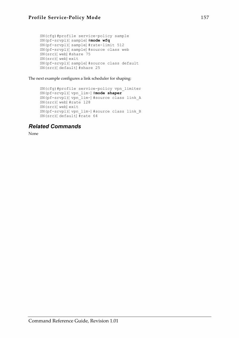
Profile Service-Policy Mode 157
Command Reference Guide, Revision 1.01
SN(cfg)#profile service-policy sample SN(pf-srvpl)[sample]#mode wfq SN(pf-srvpl)[sample]#rate-limit 512 SN(pf-srvpl)[sample]#source class web SN(src)[web]#share 75 SN(src)[web]exit SN(pf-srvpl)[sample]#source class default SN(src)[default]#share 25
The next example configures a link scheduler for shaping:
SN(cfg)#profile service-policy vpn_limiter SN(pf-srvpl)[vpn_lim~]#mode shaper SN(pf-srvpl)[vpn_lim~]#source class link_A SN(src)[web]#rate 128 SN(src)[web]exit SN(pf-srvpl)[vpn_lim~]#source class link_B SN(src)[default]#rate 64
Related Commands None
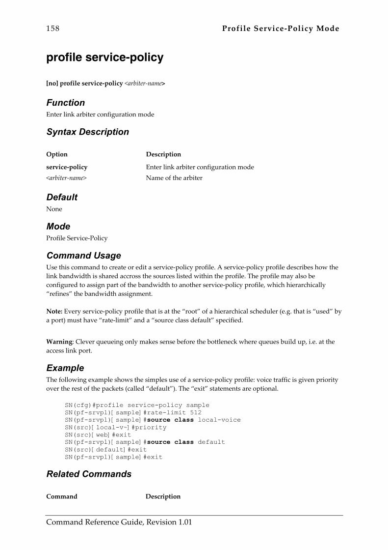
158 Profile Service-Policy Mode
Command Reference Guide, Revision 1.01
profile service-policy [no] profile service-policy <arbiter-name>
Function Enter link arbiter configuration mode
Syntax Description Option Description
service-policy <arbiter-name>
Enter link arbiter configuration mode Name of the arbiter
Default None
Mode Profile Service-Policy
Command Usage Use this command to create or edit a service-policy profile. A service-policy profile describes how the link bandwidth is shared accross the sources listed within the profile. The profile may also be configured to assign part of the bandwidth to another service-policy profile, which hierarchically “refines” the bandwidth assignment. Note: Every service-policy profile that is at the “root” of a hierarchical scheduler (e.g. that is “used” by a port) must have “rate-limit” and a “source class default” specified.
Warning: Clever queueing only makes sense before the bottleneck where queues build up, i.e. at the access link port.
Example The following example shows the simples use of a service-policy profile: voice traffic is given priority over the rest of the packets (called “default”). The “exit” statements are optional.
SN(cfg)#profile service-policy sample SN(pf-srvpl)[sample]#rate-limit 512 SN(pf-srvpl)[sample]#source class local-voice SN(src)[local-v~]#priority SN(src)[web]#exit SN(pf-srvpl)[sample]#source class default SN(src)[default]#exit SN(pf-srvpl)[sample]#exit
Related Commands Command Description

Profile Service-Policy Mode 159
Command Reference Guide, Revision 1.01
source Enter source configuration mode
rate-limit Limit interface rate
mode Arbitration scheme of this service-policy profile
160 Profile Service-Policy Mode
Command Reference Guide, Revision 1.01
rate-limit [no] rate-limit <value> [ header-length <option-value> ]
Function Limit interface rate
Syntax Description Option Description
<value> header-length <option-value>
Rate limit in kilobits modem encapsulation overhead key-word framing bytes needed to carry an ip packet (default 18)
Default Required command, default header-length is 18
Mode Profile Service-Policy
Command Usage Use this command to match the link scheduling with the bandwidth of the link – for instance the acess link bandwidth of an external modem. When the framing of the link is different from ethernet (18 bytes) the optional “header-length” parameter configures how many bytes are added to the each IP packet length when the bandwidth usage is calculated. When a link uses PPP with header compression the average frame length may even be shorter than packet contained. Use a negative “header-length” value to specify the average encapsulation gain. Warning: even for a serial port service-policy profile a rate-limit must be specified because the rate is determined by the external modem.
Example The following example shows a configuration, which assures that non-voice packets (“default”) are queued such that voice plus data traffic is limited to 512 kilobits per second.
SN(cfg)#profile service-policy sample SN(pf-srvpl)[sample]#rate-limit 512 SN(pf-srvpl)[sample]#source class local-voice SN(src)[local-v~]#priority SN(src)[web]#exit SN(pf-srvpl)[sample]#source class default SN(src)[default]#exit SN(pf-srvpl)[sample]#exit
Related Commands None
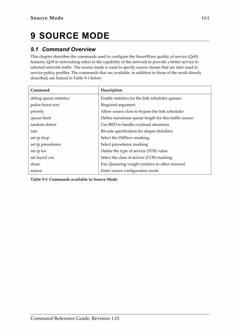
Source Mode 161
Command Reference Guide, Revision 1.01
9 SOURCE MODE 9.1 Command Overview This chapter describes the commands used to configure the SmartWare quality of service (QoS) features. QoS in networking refers to the capability of the network to provide a better service to selected network traffic. The source mode is used to specify source classes that are later used in service-policy profiles. The commands that are available, in addition to those of the modi already described, are listend in Table 9-1 below:
Command Description
debug queue statistics police burst-size priority queue-limit random-detect rate set ip dscp set ip precedence set ip tos set layer2 cos share source
Enable statistics for the link scheduler queues Required argument Allow source class to bypass the link scheduler Define maximum queue length for this traffic source Use RED to handle overload situations Bit-rate specification for shaper (kilobits) Select the DiffServ marking Select precedence marking Define the type of service (TOS) value Select the class of service (COS) marking Fair Queueing weight (relative to other sources) Enter source configuration mode
Table 9-1: Commands available in Source Mode
162 Source Mode
Command Reference Guide, Revision 1.01
debug queue statistics [no] debug queue statistics [ <value> ]
Function Enable statistics gathering for the link scheduler queues
Syntax Description Option Description
queue statistics <value>
Debug link scheduler operations enable statistics gathering Level of detail (value in the range from 1 to 4)
Default No debug queue statistics
Mode Source
Command Usage This command determines the amount of statistics gathered by the link scheduler queues. Link scheduler queues exist for each “source” defined in the active service-policy profiles. The information can be inspected using the “show service-policy” command. Statistics are reset whenever you change settings of the profile. Level Information
0 (no) only momentary queue length available (packets in queue at the time of command execution).
1 adds packet counters: showing packets “passed”, “queued” and “discarded” separately. Packets that were “passed” , did not have to wait at all (bandwidth not yet fully used). Packets that were “queued” arrived earlier that their rate limit permitted and had to wait. Packets that were “discarded” arrived when the queue was already full or were were chosen by the random detect algorithm to be discarded (if RED was enabled) or they violated the traffic policing specified useing the “police” command.
2 adds byte counters for the same three cases as listed above.
3 adds a peak queue length variable showing the maximum number of packets waiting since the last restart or change of the profile settings.
4 adds delay time monitoring: maximum and average delay percieved by the packets that have been queued are traced.
Source Mode 163
Command Reference Guide, Revision 1.01
Packets that did not have to wait at all (“passed”) are not included in the average delay figure.
Under some circumstances, i.e. when a source is given priority and no packet markings are requested, no queue exists and therefore no statics will be available. Note: When used in “source class” mode, this command acts on this specific traffic class only. The command can also be used in “source policy” mode where it acts on all traffic classes served further down the hierarchy or it can be used in “profile service-police” mode where it defines a default for all traffic classes of the profile. Settings further down the hierarchy override previous (default) settings. Warning: collection of statistics is time-consuming and may affect system performance. You should only enable queue statistics for debugging purposes.
Example The following examples show the impact of the debug queue settings:
SN(src)[web]#debug queue statistics 4 ... SN#show service-policy web - packets in queue: 0 - peak queue level: 16 - packets passed: 1192 - bytes passed: 61818 - packets queued: 121 - bytes queued: 6263 - packets discarded: 0 - bytes discarded: 0 - average delay: 8.89 ms - max delay: 20.63 ms
SN(cfg)#no debug queue statistics ... SN#show service-policy web - packets in queue: 0
Related Commands Command Description
show service-policy Displays link arbitration status
164 Source Mode
Command Reference Guide, Revision 1.01
police burst-size [no] police <average> burst-size <tolerance>
Function required argument
Syntax Description Option Description
<average> burst-size <tolerance>
average rate permitted (kbps) required argument burst size tolerated (kilobits ahead of schedule)
Default No police selected
Mode Source
Command Usage Use this command to protect your network from a traffic class generating excessive load. Policing is used to check if a source conforms to an agreed traffic limit. Packets violating the rate limit are discarded. The tolerance value determines how much jitter the traffic may have and still conform to the rate limit. If zero tolerance is specified the policing checks the time between any two packets to be the packet length of the former divided by the allowed rate. If the second packet arrives before that time — ahead of schedule — it is dropped. The tracking method called “leaky bucket” is used to check conformance, if a non-zero tolerance is specified. The scheduled arrival time is calculated as described before, but the next packet may arrive a certain time before schedule (tolerance value divided by the average rate). Note: When used in “source class” mode, this command acts on this specific traffic class only. The command can also be used in “source policy” mode where it acts on all traffic classes served further down the hierarchy or it can be used in “profile service-police” mode where it defines a default for all traffic classes of the profile. Settings further down the hierarchy override previous (default) settings. Warning: for TCP traffic, the use of queueing (wfq or shaping) is recommended.
Example The following example limits the source to 64 kilobits allowing 0.5 seconds of jitter:
SN(cfg)#profile service-policy sample SN(pf-srvpl)[sample]#source class xxx SN(src)[xxx]#police 64 burst-size 32

Source Mode 165
Command Reference Guide, Revision 1.01
Related Commands None
166 Source Mode
Command Reference Guide, Revision 1.01
priority [no] priority
Function allow source class to bypass the link scheduler
Syntax Description Option Description
This command has no keywords or options
Default None
Mode Source
Command Usage When given “priority” the traffic source is not affected by the link scheduling. The packet is immediately forwarded and never delayed. Bandwidth not used by the “priority” traffic is given to the other traffic sources according to the profile. Packet markings (set ip dscp, etc.) can be applied to “priority” traffic but all queueing-related commands (queue-limit, rate, share, random-detect, etc.) have no effect on this source. Warning: make sure that priority is only given to well-behaving inherently limited sources (e.g. voice traffi generated by the SmartNode). If the priority traffic exceeds the rate-imit of the profile erratic behaviour will result.
Example The following example allows the voice traffic generated by the SmartNode to bypass the link scheduler. If voice traffic currently used 200 kilobits the remaining 300 kilobits will be equally shared by the ACL-classified source “web” the all the other sources (“default”).
SN(cfg)#profile service-policy sample SN(pf-srvpl)[sample]#rate-limit 500 SN(pf-srvpl)[sample]#source class local-voice SN(src)[local-v~]#priority SN(pf-srvpl)[sample]#source class web SN(src)[web]#share 50 SN(pf-srvpl)[sample]#source class default SN(src)[default]#share 50
Related Commands Command Description

Source Mode 167
Command Reference Guide, Revision 1.01
rate-limit Limit interface rate
168 Source Mode
Command Reference Guide, Revision 1.01
queue-limit [no] queue-limit <value>
Function Define maximum queue length for this traffic source
Syntax Description Option Description
<value> number packets that can be queued
Default Queue-limit 16
Mode Source When used in “source class” mode, this command acts on this specific traffic class only. The command can also be used in “source policy” mode where it acts on all traffic classes served further down the hierarchy or it can be used in “profile service-police” mode where it defines a default for all traffic classes of the profile. Settings further down the hierarchy override previous (default) settings.
Command Usage Use this command to define the size of the queue used for this traffic source. For TCP traffic a bigger queue size allows more parallel connections to achieve a window size suffiscient for the round-trip time. Warning: to protect the system from running out of packet memory the overall number of packets queued in all link scheduler queues is limited (200 packets in the current releases). Degraded performance will result if this limit is frequently reached.
Example The following example shows the use of the command in different modes: the queue limit of 10 defined in the service-policy profile acts as a default value and is therefore used for the sources “A” and the “default”, whereas source “B” has an explicit setting of 30 overriding the previous value.
SN(cfg)#profile service-policy sample SN(pf-srvpl)[sample]#rate-limit 500 SN(pf-srvpl)[sample]#queue-limit 10 SN(pf-srvpl)[sample]#source class A SN(src)[A]#share 40 SN(pf-srvpl)[sample]#source class B SN(src)[B]#share 40 SN(src)[B]#queue-limit 30 SN(pf-srvpl)[sample]#source class default SN(src)[local-v~]#share 20

Source Mode 169
Command Reference Guide, Revision 1.01
Related Commands None

170 Source Mode
Command Reference Guide, Revision 1.01
random-detect [no] random-detect [ <burst-tolerance> ]
Function Use RED to handle overload situations with many long-lasting TCP connections like email traffic.
Syntax Description Option Description
<burst-tolerance> optional: burst tolerance index (value in the range from 1 to 10), default if omitted is 4
Default None
Mode Source
Command Usage TCP streams continually increment their window size until they somewhere cause a router queue to overflow, which causes a packet to be lost. Thereafter the TCP source resumes transmission with half the window size – again slowly incrementing. Under some circumstances this saw-tooth behaviour of multiple TCP sources may get synchronized because once a queue is full, several streams will suffer from packet loss. A bad situation occurs, when many sources oscillate synchronously and half of the network bandwidth remains unused. To avoid this effect a scheme called random early detect (RED) has been proposed which radomly drops packets even before the queue is completely full. The drop probability grows with the queue-length. The optional burst-tolerance parameter specifies a filter that avarages the queue-length to allow bursts to pass when the average load is low. The averaging uses a weighted sum where the current
value has weight b
21 and the previous average has weight
b
211− where b is the burst-tolerance
parameter. Warning: for short transfers like web page requests the use of RED is not recommended. Use a larger queue instead.
Example The following example enables RED for mail traffic with the default burst-tolerance, which is recommended (given the traffic is suitably classified):
SN(cfg)#profile service-policy sample SN(pf-srvpl)[sample]#source class mail SN(src)[mail]#random-detect

Source Mode 171
Command Reference Guide, Revision 1.01
Related Commands Command Description
queue-limit Define maximum queue length for this traffic source

172 Source Mode
Command Reference Guide, Revision 1.01
rate rate <kilobits>
Function Bit-rate specification for shaper (kilobits)
Syntax Description Option Description
<kilobits> Bandwidth limit for this source
Default None
Mode Source
Command Usage Use this command to specify the maximum bitrate to which the source is to be limited. If more packets arrive they are queued and if the queue overflows they are dropped. Shaping is useful if a traffic source must be rate-limited to obey to an agreement with the provider. Warning: if the service-policy profile this source belongs to is not configured for “shaper” mode, the setting has no effect.
Example The following example specifies that traffic source A is shaped to 128 kbps:
SN(cfg)#profile service-policy sample SN(pf-srvpl)[sample]#mode shaper SN(pf-srvpl)[sample]#source class A SN(src)[A]#rate 128
Related Commands Command Description
mode Set arbitration scheme of selected service policy profile

Source Mode 173
Command Reference Guide, Revision 1.01
set ip dscp [no] set ip dscp <value>
Function Select the DiffServ marking
Syntax Description Option Description
ip dscp <value>
ip layer select DiffServ marking Differentiated Services Code Point value
Default By default the DCSP value of routed packets is unchanged, packets generated by the SmartNode have a value of 0.
Mode Source
Command Usage Packet markings are used to take advantage of network QoS feature. The “set” commands put information in the IP packet header to inform other routers about the type of data contained in the packet. Use the “set ip dscp” command to specify the Differentiated Services Code Point marking to be applied to the packet.
Example The following example specifies packets from traffic source A to be marked with the dscp value of 47:
SN(cfg)#profile service-policy sample SN(pf-srvpl)[sample]#source class A SN(src)[A]#set ip dscp 47
Related Commands Command Description
set ip tos Define the type of service (TOS) value
set ip precedence Select precedence marking
set layer2 cos Select class of service (COS) marking
174 Source Mode
Command Reference Guide, Revision 1.01
set ip precedence [no] set ip precedence <value>
Function select precedence marking
Syntax Description Option Description
ip precedence <value>
ip layer select precedence marking precedence field value
Default By default the precedence value of routed packets is unchanged, packets generated by the SmartNode have a value of 0.
Mode Source
Command Usage Packet markings are used to take advantage of network QoS feature. The “set” commands put information in the IP packet header to inform other routers about the type of data contained in the packet. Use the “set ip precedence” command to specify the Precedence marking to be applied to the packet.
Example The following example specifies packets from traffic source A to be marked with the the precedemce value of 3:
SN(cfg)#profile service-policy sample SN(pf-srvpl)[sample]#source class A SN(src)[A]#set ip precedence 3
Related Commands Command Description
set ip tos Define the type of service (TOS) value
set ip dscp Select DiffServ marking
set layer2 cos Select class of service (COS) marking
Source Mode 175
Command Reference Guide, Revision 1.01
set ip tos [no] set ip tos <value>
Function Define the type of service (TOS) value
Syntax Description Option Description
<value> TOS field field value
Default By default the TOS value of routed packets is unchanged, packets generated by the SmartNode have a value of 0.
Mode Source
Command Usage Packet markings are used to take advantage of network QoS feature. The “set” commands put information in the IP packet header to inform other routers about the type of data contained in the packet. Use the “set ip tos” command to specify the Type-of-Service field value to be applied to the packet.
Example The following example specifies packets from traffic source A to be marked with the type-of-service of 4:
SN(cfg)#profile service-policy sample SN(pf-srvpl)[sample]#source class A SN(src)[A]#set ip tos 4
Related Commands Command Description
set ip dscp Select the DiffServ marking
set ip precedence Select precedence marking
set layer2 cos Select the class of service (COS) marking
176 Source Mode
Command Reference Guide, Revision 1.01
set layer2 cos [no] set layer2 cos <value>
Function Select the class of service (COS) marking
Syntax Description Option Description
layer2 cos <value>
layer 2 select class of service (COS) marking COS value
Default By default the class of service value of routed packets is unchanged, packets generated by the SmartNode have a value of 0.
Mode Source
Command Usage Packet markings are used to take advantage of network QoS feature. The “set” commands put information in the IP packet header to inform other routers about the type of data contained in the packet. Use the “set layer2 cos” command to specify the layer 2 class-of-service marking that has to be applied to the packet. Warning: the port must be configured for a suitable encapsulation and frame-format for the setting to have an effect – e.g. an Ethernet port must be configured for “frame-format dot1q”.
Example The following example specifies packets from traffic source A to be marked with layer two class-of-service 3:
SN(cfg)#profile service-policy sample SN(pf-srvpl)[sample]#source class A SN(src)[A]#set layer2 cos 3
Related Commands Command Description
set ip dscp Select the DiffServ marking
set ip precedence Select precedence marking
set ip tos Define the type of service (TOS) value
Source Mode 177
Command Reference Guide, Revision 1.01
share share <percentage>
Function Fair Queueing weight (relative to other sources)
Syntax Description Option Description
<percentage> relative weight of this source
Default If more than one source is listed for a service-policy profile running in weighted fair queueing mode, a “share” value must explicitely be specified. It can be omitted only if a single source receives all the bandwidth.
Mode Source
Command Usage Use this command to define the ratio by which the bandwidth is shared among the sources in “weighted fair queueing” (WFQ) mode. The percentages specified for the different sources need not add up to 100%. In fact you might as well specify 3:1 for 75:25, but percentage values are easier to read.
Example The following example web traffic gets three times the bandwidth of the remaining traffic:
SN(cfg)#profile service-policy sample SN(pf-srvpl)[sample]#source class web SN(src)[web]#share 75 SN(src)[web]exit SN(pf-srvpl)[sample]#source class default SN(src)[default]#share 25
The next example shows a case where a “share”setting is not needed. The voice traffic bypasses the link scheduler and the remaining “default” is the only source.
SN(cfg)#profile service-policy sample SN(pf-srvpl)[sample]#source class local-voice SN(src)[web]#priority SN(src)[web]exit SN(pf-srvpl)[sample]#source class default
Related Commands

178 Source Mode
Command Reference Guide, Revision 1.01
Command Description
mode Set arbitration scheme of selected service policy profile
rate Bit-rate specification for shaper (kilobits)
Source Mode 179
Command Reference Guide, Revision 1.01
source [no] source { ( class <source-name> ) | ( policy <source-name> ) }
Function Enter source configuration mode
Syntax Description Option Description
class <source-name> policy <source-name>
for an ACL class Traffic class name (as defined in ACL) for a hierarchical policy-map Name of the sub-arbiter
Default None
Mode Source
Command Usage Use this command to have a (traffic) source scheduled by the service-policy profile you are editing. The source command defines a separate handling for a specific traffic class or hierarchically referenced service-policy profile. For the “source class” mode, the traffic class must either be defined with a permit criteria of the ACL or it can be one of the predefined classes listed in Table 9-2 below. The “source policy” mode connects the output of another service-policy profile to the current profile – thereby defining a hierarchical link scheduler. A source statement for the class “default” is mandatory for each link scheduler – you must specify how much bandwidth is given to the remaining sources, but only in one of the profiles for hierarchical schedulers. Class Name Usage
local-voice voice traffic generated by the SmartNode
local-default remainig traffic generated by the SmartNode (signalling and anagement)
default the rest of the traffic (unclassifed or clases not listed as sources in the service-policy profile)
Table 9-2: Predefined Traffic Classes
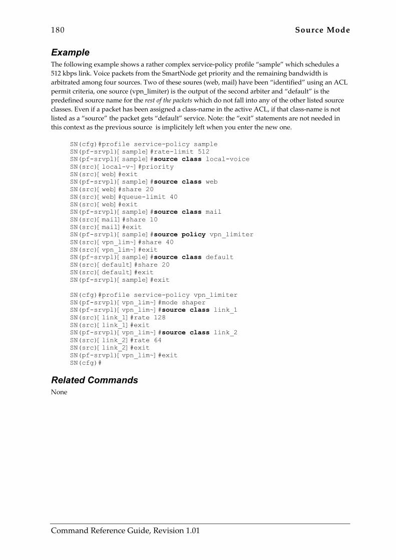
180 Source Mode
Command Reference Guide, Revision 1.01
Example The following example shows a rather complex service-policy profile “sample” which schedules a 512 kbps link. Voice packets from the SmartNode get priority and the remaining bandwidth is arbitrated among four sources. Two of these soures (web, mail) have been “identified” using an ACL permit criteria, one source (vpn_limiter) is the output of the second arbiter and “default” is the predefined source name for the rest of the packets which do not fall into any of the other listed source classes. Even if a packet has been assigned a class-name in the active ACL, if that class-name is not listed as a “source” the packet gets “default” service. Note: the “exit” statements are not needed in this context as the previous source is implicitely left when you enter the new one.
SN(cfg)#profile service-policy sample SN(pf-srvpl)[sample]#rate-limit 512 SN(pf-srvpl)[sample]#source class local-voice SN(src)[local-v~]#priority SN(src)[web]#exit SN(pf-srvpl)[sample]#source class web SN(src)[web]#share 20 SN(src)[web]#queue-limit 40 SN(src)[web]#exit SN(pf-srvpl)[sample]#source class mail SN(src)[mail]#share 10 SN(src)[mail]#exit SN(pf-srvpl)[sample]#source policy vpn_limiter SN(src)[vpn_lim~]#share 40 SN(src)[vpn_lim~]#exit SN(pf-srvpl)[sample]#source class default SN(src)[default]#share 20 SN(src)[default]#exit SN(pf-srvpl)[sample]#exit SN(cfg)#profile service-policy vpn_limiter SN(pf-srvpl)[vpn_lim~]#mode shaper SN(pf-srvpl)[vpn_lim~]#source class link_1 SN(src)[link_1]#rate 128 SN(src)[link_1]#exit SN(pf-srvpl)[vpn_lim~]#source class link_2 SN(src)[link_2]#rate 64 SN(src)[link_2]#exit SN(pf-srvpl)[vpn_lim~]#exit SN(cfg)#
Related Commands None

Profile NAPT Mode 181
Command Reference Guide, Revision 1.01
10 PROFILE NAPT MODE 10.1 Command Overview In this mode you may configure a SmartNode’s Network Address Port Translation (NAPT). Two key problems facing the Internet are depletion of IP address space and scaling in routing. NAPT is a feature that allows the IP network of an organization to appear from the outside to use different IP address space than that which it is actually using. Thus, NAPT allows an organization with nonglobally routable addresses to connect to the Internet by translating those addresses into globally routable address space. NAPT also allows a more graceful renumbering strategy for organizations that are changing service providers or voluntarily renumbering into classless interdomain routing (CIDR) blocks. NAPT is described in RFC 1631. The commands that are available in this mode are listed in Table 10-1 below:
Command Description
icmp default profile napt static
Set default ICMP server Create Network Address Port Translation (NAPT) profile Appends or removes static NAPT entry
Table 10-1: Commands available in Profile NAPT Mode
182 Profile NAPT Mode
Command Reference Guide, Revision 1.01
icmp default [no] icmp default <host>
Function Set default ICMP server
Syntax Description Option Description
<host>
IP address of the host in the local network that shall get ICMP messages from the global network.
Default None
Mode Profile NAPT
Command Usage ICMP Requests and Responses do not have port numbers to determine the disired destination. Only the destination IP address is used when forwarding ICMP Request/Response packets. NAPT handles this situation by providing a single default IP address for all ICMP Requests from the global network. This address can either be another address for the local router or a private address. The no form configures that ICMP messages are not forwarded to the local network.
Example The following example configures the local host 10.0.0.2 to be the destination of received ICMP Requests from the global network:
SN(cfg)#profile napt global SN(pf-napt)[global]#icmp default 10.0.0.2
Related Commands Command Description
profile napt Creates or removes NAPT profiles
static Adds or removes static translation entries
use profile napt Binds a NAPT profile to an interface
show profile napt Displays information about a NAPT profile
show interface napt Displays information about the NAPT binding of an interface
Profile NAPT Mode 183
Command Reference Guide, Revision 1.01
profile napt [no] profile napt <napt-profile_name>
Function Create Network Address Port Translation (NAPT) profile
Syntax Description Option Description
<napt-profile_name> Network Address Port Translation profile name
Default None
Mode Profile NAPT
Command Usage The Network Address Port Translation (NAPT) uses a single IP address to interface numerous “corporate” hosts to the Internet. All the hosts on the global side (global interface) view all hosts on the local side (local interface) as a single Internet host. The local hosts continue to use their corporate addresses. The translation is not based solely upon IP addresses but the TCP/UDP port number and ICMP message IDs used by applications when communicating to each other. A NAPT profile can be bound to the global interface. The profile defines, which packets to ports destined to the global interface should be forwarded to which hosts on the local network. Furthermore, a host can be specified to get all ICMP messages, the ICMP default server. This command creates and enters new profiles or enters existing profile. After entering the profile, the commands static and icmp default are available to configure the profile. The no form removes an existing profile.
Example The following example creates a new NAPT profile with name “global”:
SN(cfg)#profile napt global The next example removes the existing “global” NAPT profile:
SN(cfg)#no profile napt
Related Commands Command Description
icmp default Configures the ICMP default server

184 Profile NAPT Mode
Command Reference Guide, Revision 1.01
static Adds or removes static translation entries
use profile napt Binds a NAPT profile to an interface
show profile napt Displays NAPT profile information
show interface napt Displays NAPT binding of an interface
Profile NAPT Mode 185
Command Reference Guide, Revision 1.01
static [no] static <protocol> <port> <host>
Function Appends or removes static NAPT entry
Syntax Description Option Description
<protocol> <port> <host>
May take the value “udp” or “tcp”. Defines that a port of the specified transport layer protocol is translated Destination port number of the specified transport protocol. Destination IP address the packet’s destination new destination in the local network.
Default None
Mode Profile NAPT
Command Usage Adds a static NAPT translation entry. An entry contains the transport layer protocol and the transport layer destination port number to select packets received on the global port. If received packets match, they are forwarded to the specified destination host in the local network. This allows for example to forward Web traffic (TCP port 80) to a web server in the local network. The no form removes a static entry. Warning: Modifications of static entries in a NAPT profile that is bound to an IP interface reconfigure the static port-mapping table of the router immediately. Although, if you remove a static entry, the router continues forwarding packets to the previousely-configured host in the local network until the connection terminates or a timeout occurs.
Example The following example adds a static translation entry. All packets received TCP packets on the global interface to port 80 are forwarded to the local network host 10.0.0.2:
SN(cfg)#profile napt global SN(pf-napt)[global]#static tcp 80 10.0.0.2
The next example removes the previousely added static entry from the mapping table:
SN(pf-napt)[global]#no static tcp 80

186 Profile NAPT Mode
Command Reference Guide, Revision 1.01
Related Commands Command Description
profile napt Creates or removes NAPT profiles
icmp default Configures the ICMP default server
use profile napt Binds a NAPT profile to an interface
show profile napt Displays NAPT profile information
show interface napt Displays the NAPT profile binding of an IP interface
Profile Call-Progress-Tone Mode 187
Command Reference Guide, Revision 1.01
11 PROFILE CALL-PROGRESS-TONE MODE
11.1 Command Overview The tones informing about the call state are refered to as call-progress-tones. A call progress tone can be a tone you hear when you lift the handset and the network is ready, a tone you hear when the called party number is complete and the remote extension is ringing, or a tone you hear when the remote extension is busy. Fifteen tones can be configured with their frequency and duration characteristics. The configuration for each tone is stored in so called “call-progress-tone profile”. In this mode you may configure a SmartNode’s call-progress-tone profile. The commands that are available in this mode are listed in Table 11-1 below:
Command Description
high-frequency high-frequency-level low-frequency low-frequency-level off1 off2 on1 on2 profile call-progress-tone
Configure tone high frequency Configure call-progress tone high frequency level Configure tone low frequency Configure call-progress tone low frequency level Configure tone interspace 1 Configure tone interspace 2 Configure tone duration 1 Configure tone duration 2 Enter call-progress tone configuration mode
Table 11-1: Commands available in Profile Call-Progress-Tone Mode
188 Profile Call-Progress-Tone Mode
Command Reference Guide, Revision 1.01
high-frequency high-frequency <high_frequency>
Function Configure tone high frequency
Syntax Description Option Description
<high_frequency> Frequency in Hz
Default The default <high_frequency> option is the default value for call-progress-tone defaultDialtone: 0 Hz (this means the high frequency is not played back).
Mode Profile Call-Progress-Tone
Command Usage Defines the frequency of the higher of the two sine waves that define a call-progress tone. Warning: 0 Hz should only be used together with high-frequency-level mute.
Example The following example configures the high frequency of the call-progress tone named ‘myTone’ to 425 Hz
SN(pf-callp)[myTone1]#high-frequency 425
Related Commands Command Description
low-frequency Configure tone low frequency
Profile Call-Progress-Tone Mode 189
Command Reference Guide, Revision 1.01
high-frequency-level high-frequency-level { mute | <high_frequency_level> }
Function Configure call-progress tone high frequency level
Syntax Description Option Description
mute <high_frequency_level>
Mute high frequency completely Frequency Level in dBm, from –31dBm to +3dBm
Default The default <high_ frequency_level > option is the default value for call-progress-tone defaultDialtone: mute (this means the high frequency is not played back).
Mode Profile Call-Progress-Tone
Command Usage Defines the level of the higher of the two sine waves that define a call-progress tone.
Example The following example configures the high frequency level of the call-progress tone named ‘myTone’ to 0dBm
SN(pf-callp)[myTone1]#high-frequency-level 0
Related Commands Command Description
low-frequency level Configure call-progress tone low frequency level

190 Profile Call-Progress-Tone Mode
Command Reference Guide, Revision 1.01
low-frequency low-frequency <low_frequency>
Function Configure tone low frequency
Syntax Description Option Description
<low_frequency> Frequency in Hz
Default The default <low_frequency> option is the default value for call-progress-tone defaultDialtone: 425 Hz (This value may differ according to the country).
Mode Profile Call-Progress-Tone
Command Usage Defines the frequency of the lower of the two sine waves that define a call-progress tone. Warning: 0 Hz should only be used together with low-frequency-level mute.
Example The following example configures the low frequency of the call-progress tone named ‘myTone’ to 425Hz
SN(pf-callp)[myTone1]#low-frequency 425
Related Commands Command Description
high-frequency Configure tone high frequency
Profile Call-Progress-Tone Mode 191
Command Reference Guide, Revision 1.01
low-frequency-level low-frequency-level { mute | <low_frequency_level> }
Function Configure call-progress tone low frequency level
Syntax Description Option Description
mute <low_frequency_level>
Mute low frequency completely Frequency Level in dBm, from –31dBm to +3dBm
Default The default <low_ frequency_level > option is the default value for call-progress-tone defaultDialtone: 0 (This value may differ according to the country).
Mode Profile Call-Progress-Tone
Command Usage Defines the level of the lower of the two sine waves that define a call-progress tone.
Example The following example configures the low frequency level of the call-progress tone named ‘myTone’ to 0dBm
SN(pf-callp)[myTone1]#low-frequency-level 0
Related Commands Command Description
high-frequency level Configure call-progress tone high frequency level
192 Profile Call-Progress-Tone Mode
Command Reference Guide, Revision 1.01
off1 off1 <off1>
Function Configure tone interspace 1
Syntax Description Option Description
<off1> Duration in ms
Default The default <off1> option is the default value for call-progress-tone defaultDialtone: 0 (This value may differ according to the country).
Mode Profile Call-Progress-Tone
Command Usage Each call-progress tone is played in a cadenced pattern of tone and silence. This command defines the duration of the first silence phase (interspace between first and second tone phase).
Example The following example configures the tone interspace 1 of the call-progress tone named ‘myTone’ to 1 second
SN(pf-callp)[myTone1]#off1 1000
Related Commands Command Description
on1 Configure tone duration 1
Profile Call-Progress-Tone Mode 193
Command Reference Guide, Revision 1.01
off2 off2 <off1>
Function Configure tone interspace 2
Syntax Description Option Description
<off2> Duration in ms
Default The default <off2> option is the default value for call-progress-tone defaultDialtone: 0 (This value may differ according to the country).
Mode Profile Call-Progress-Tone
Command Usage Each call-progress tone is played in a cadenced pattern of tone and silence. This command defines the duration of the second silence phase (interspace between second tone and first tone phase).
Example The following example configures the tone interspace 2 of the call-progress tone named ‘myTone’ to half a second
SN(pf-callp)[myTone1]#off2 500
Related Commands Command Description
on2 Configure tone duration 2
194 Profile Call-Progress-Tone Mode
Command Reference Guide, Revision 1.01
on1 on1 <on1>
Function Configure tone duration 1
Syntax Description Option Description
<on1> Duration in ms
Default The default <on1> option is the default value for call-progress-tone defaultDialtone: 5000 (This value may differ according to the country).
Mode Profile Call-Progress-Tone
Command Usage Each call-progress tone is played in a cadenced pattern of tone and silence. This command defines the duration of the first tone phase.
Example The following example configures the tone duration 1 of the call-progress tone named ‘myTone’ to one second
SN(pf-callp)[myTone1]#on1 1000
Related Commands Command Description
off1 Configure tone interspace 1
Profile Call-Progress-Tone Mode 195
Command Reference Guide, Revision 1.01
on2 on2 <on2>
Function Configure tone duration 2
Syntax Description Option Description
<on2> Duration in ms
Default The default <on2> option is the default value for call-progress-tone defaultDialtone: 0 (This value may differ according to the country).
Mode Profile Call-Progress-Tone
Command Usage Each call-progress tone is played in a cadenced pattern of tone and silence. This command defines the duration of the second tone phase.
Example The following example configures the tone duration 2 of the call-progress tone named ‘myTone’ to 250 milliseconds
SN(pf-callp)[myTone1]#on2 250
Related Commands Command Description
off2 Configure tone interspace 2
196 Profile Call-Progress-Tone Mode
Command Reference Guide, Revision 1.01
profile call-progress-tone [no] profile call-progress-tone <name>
Function Enter call-progress tone configuration mode / add a new call-progress tone
Syntax Description Option Description
<name> Call-progress tone name
Default Adding a new call-progress tone profile (i.e. typing for <name> a name that is not yet given to a call-progress-tone) will give the default dial tone parameters to the new profile (see default values of mode commands highFrequency, lowFrequency, highFrequencyLevel, lowFrequencyLevel, on1, off1, on2, off2).
Mode Administrator exec
Command Usage If a new call-progress tone needs to be added to the playable tones, this command creates one. If a call-progress tone is no more needed, this command with the [no] prefix removes it. If a call-progress tone’s parameters need to be changed, this command enters the configuration mode Warning: Only 15 different call-progress tones can be configured at a time.
Example The following example adds the tone with name ‘dialToneGB’ to the set of known tones.
SN(cfg)#profile call-progress-tone dialToneGB The next example removes the tone profile created above:
SN(cfg)#no profile call-progress-tone dialToneGB
Related Commands Command Description
profile tone-set Enter tone set profile configuration

Profile Tone-Set Mode 197
Command Reference Guide, Revision 1.01
12 PROFILE TONE-SET MODE 12.1 Command Overview In this mode you may configure a SmartNode’s tone set. Several tones can be configured with their frequency and duration characteristics. The setting for each of the tones is stored in so called call-progress-tone profile as desribed in Chapter XX, “XX”, in this guide. A set of these tones is later mapped to their respective call state in a tone-set profile. The tone-set profile is used by the CS context and applies to all PSTN interfaces on the CS context. The commands that are available in this mode are listed in Table 12-1 below:
Command Description
map profile tone-set
Map a sessioncontrol tone event to a configured call-progress tone Enter tone set profile configuration mode
Table 12-1: Commands available in Profile Tone-Set Mode
198 Profile Tone-Set Mode
Command Reference Guide, Revision 1.01
map [no] map { ( call_progress_tone <internal_tone_name> <call_progress_tone_name> ) }
Function Map a sessioncontrol tone event to a configured call-progress tone
Syntax Description Option Description
<internal_tone_name> <call_progress_tone_name>
Internal tone name Call-progress tone name
Default The following mappings are defaults: dialtone = default dial tone
alertingtone = default alerting tone
busytone = default busy tone
Mode Profile Tone-Set
Command Usage Sessioncontrol wants to play several tones: dialtone, alertingtone, busytone (called ‘internal tones’). To define how these tones sound like, the tone-set profile provides a mapping to configured call-progress tones. Note that each tone-set profile can define a different mapping, and that only the use of the profiles defines which mapping applies. The command has immediate effect, but does not influence existing voice connections.
Example The following example replaces the ‘defaultDialtone’ call-progress tone by the ‘dialtoneGB’ in the ‘mySet’ tone-set profile. When configured, sessioncontrol plays the new ‘dialtoneGB’ if the ‘default’ tone-set is used.
SN(pf-tones)[mySet]#no map dialtone defaultDialtone SN(pf-tones)[mySet]#map dialtone dialtoneGB
Related Commands Command Description
profile call-progress tone Enter call-progress tone confiuguration mode
use tone-set-profile Link tone-set profile to the selected interface
Profile Tone-Set Mode 199
Command Reference Guide, Revision 1.01
profile tone-set profile tone-set <name>
Function Enter tone set profile configuration mode
Syntax Description Option Description
<name> Name of the tone set
Default One tone-set profile with ‘default’ as <name> is configured.
Mode Administrator exec
Command Usage If a new tone-set needs to be added, this command creates one (<name> can be chosen arbitrarily, max. 25 characters long). If a tone-set is no more needed, this command with the [no] prefix removes it. If a tone-set’s parameters need to be changed, this command enters the configuration mode
Example The following example creates a new tone-set called ‘mySet’
SN(cfg)#profile tone-set mySet SN(pf-tones)[mySet]#
Now call-progress tones can be mapped using the map command.
Related Commands Command Description
map Map a sessioncontrol tone event to a configured call-progress tone
use tone-set-profile Link tone-set profile to the selected interface
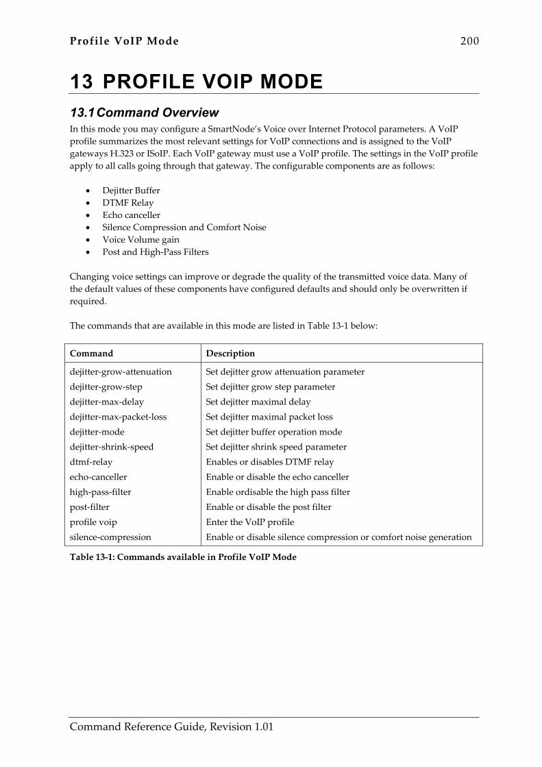
Profile VoIP Mode 200
Command Reference Guide, Revision 1.01
13 PROFILE VOIP MODE 13.1 Command Overview In this mode you may configure a SmartNode’s Voice over Internet Protocol parameters. A VoIP profile summarizes the most relevant settings for VoIP connections and is assigned to the VoIP gateways H.323 or ISoIP. Each VoIP gateway must use a VoIP profile. The settings in the VoIP profile apply to all calls going through that gateway. The configurable components are as follows:
• Dejitter Buffer • DTMF Relay • Echo canceller • Silence Compression and Comfort Noise • Voice Volume gain • Post and High-Pass Filters
Changing voice settings can improve or degrade the quality of the transmitted voice data. Many of the default values of these components have configured defaults and should only be overwritten if required. The commands that are available in this mode are listed in Table 13-1 below:
Command Description
dejitter-grow-attenuation dejitter-grow-step dejitter-max-delay dejitter-max-packet-loss dejitter-mode dejitter-shrink-speed dtmf-relay echo-canceller high-pass-filter post-filter profile voip silence-compression
Set dejitter grow attenuation parameter Set dejitter grow step parameter Set dejitter maximal delay Set dejitter maximal packet loss Set dejitter buffer operation mode Set dejitter shrink speed parameter Enables or disables DTMF relay Enable or disable the echo canceller Enable ordisable the high pass filter Enable or disable the post filter Enter the VoIP profile Enable or disable silence compression or comfort noise generation
Table 13-1: Commands available in Profile VoIP Mode

Profile VoIP Mode 201
Command Reference Guide, Revision 1.01
dejitter-grow-attenuation dejitter-grow-attenuation <dejitter_grow_attenuation>
Function Set dejitter grow attenuation parameter
Syntax Description Option Description
<dejitter_grow_attenuation> Dejitter grow attenuation
Default <dejitter_grow_attenuation> is 1.
Mode Profile VoIP
Command Usage This command sets the attenuation factor for the growth of the adaptive dejitter buffer (in static dejitter mode, the command has no effect). If the dejitter buffer recognizes increased jitter on the network, it may want to increase its size in order to handle the jitter correctly. The dejitter-grow-attenuation can limit the speed of dejitter buffer size growth. Warning: This command should only be used if the adaptive operation mode of the dejitter buffer is well known. Wrong usage can lead to dejitter buffer size instability and bad voice quality.
Example The following example sets the grow attenuation to 2.
SN(pf-voip)[myVoip]#dejitter-grow-attenuation 2
Related Commands None
202 Profile VoIP Mode
Command Reference Guide, Revision 1.01
dejitter-grow-step dejitter-grow-step <dejitter_grow_step>
Function Set dejitter grow step parameter
Syntax Description Option Description
<dejitter_grow_step> Dejitter grow step [voice packets]
Default <dejitter_grow_ step> is 1.
Mode Profile VoIP
Command Usage This command sets the grow step for the growth of the adaptive dejitter buffer (in static dejitter mode, the command has no effect). If the dejitter buffer recognizes increased jitter on the network, it may want to increase its size in order to handle the jitter correctly. The dejitter-grow-step command tells it how many more voice packets it should buffer in one growth step. Note that according to the used packetization period and codec, the grow step has different effect on the resulting dejitter delay variation. Warning: This command should only be used if the adaptive operation mode of the dejitter buffer is well known. Wrong usage can lead to dejitter buffer size instability and bad voice quality.
Example The following example sets the grow step to 2.
SN(pf-voip)[myVoip]#dejitter-grow-step 2
Related Commands None
Profile VoIP Mode 203
Command Reference Guide, Revision 1.01
dejitter-max-delay dejitter-max-delay <dejitter_max_delay>
Function Set dejitter maximal delay
Syntax Description Option Description
<dejitter_max_delay> Dejitter max delay [milliseconds]
Default < dejitter_max_delay > is 60ms
Mode Profile VoIP
Command Usage This command sets the maximum delay that the dejitter buffer is allowed to introduce in the voice path. The influence is different for static and adaptive mode. Static mode: The dejitter buffer tries to hold a constant (static) delay of half the configured max-delay, but may maximally introduce the configured max-delay. Adaptive mode: The dejitter buffer tries to minimize its delay. If network jitter is large, it may maximally introduce the configured max-delay.
Example The following example sets the dejitter max delay to 100ms.
SN(pf-voip)[myVoip]#dejitter-max-delay 100
Related Commands None Command Description
dejitter-mode Set dejitter buffer operation mode
204 Profile VoIP Mode
Command Reference Guide, Revision 1.01
dejitter-max-packet-loss dejitter-max-packet-loss <dejitter_max_packet_loss>
Function Set dejitter maximal packet loss
Syntax Description Option Description
<dejitter_max_packet_loss> Maximum packet loss
Default < dejitter_max_packet_loss > is 4
Mode Profile VoIP
Command Usage This command tells the adaptive dejitter buffer how many packets may be lost due to buffer overflow before it decides to increase the buffer size. The command has no influence in static mode. Warning: This command should only be used if the adaptive operation mode of the dejitter buffer is well known. Wrong usage can lead to dejitter buffer size instability and bad voice quality.
Example The following example sets the maximum packet loss to 3, and thus decreases reaction time on increased jitter compared to the default value.
SN(pf-voip)[myVoip]#dejitter-max-packet-loss 3
Related Commands None
Profile VoIP Mode 205
Command Reference Guide, Revision 1.01
dejitter-mode dejitter-mode { adaptive | static }
Function Set dejitter buffer operation mode
Syntax Description Option Description
adaptive static
Set adaptive dejitter buffer mode Set static dejitter buffer mode
Default The adaptive dejitter buffer mode is set by default.
Mode Profile VoIP
Command Usage Two different modes of dejitter buffer exists. The main difference between them lies in the handling of the delay they introduce in the voice path. Static mode tries to hold a constant (static) delay of half the configured dejitter-max-delay, but may maximally introduce the configured dejitter-max-delay. It is suited for networks with known and non-fluctuating jitter, or applications where voice path delay is no concern (e.g. fax or data transmission). Adaptive mode tries to minimize the delay. If network jitter is large, it may maximally introduce the configured max-delay. It is suited for networks with unknown jitter properties and applications where voice path delay is a major concern. Warning: As adaptive mode may intentionally drop voice packets to decrease buffer size, it is not suited for fax or data transmission.
Example The following example sets the dejitter mode to static.
SN(pf-voip)[myVoip]#dejitter-mode static
Related Commands Command Description
dejitter-max-delay Set dejitter maximal delay
206 Profile VoIP Mode
Command Reference Guide, Revision 1.01
dejitter-shrink-speed dejitter-shrink-speed <dejitter_shrink_speed>
Function Set dejitter shrink speed parameter
Syntax Description Option Description
<dejitter_shrink_speed> Dejitter shrink speed [voice packets]
Default None
Mode Profile VoIP
Command Usage This command sets the speed of size decrease of the adaptive dejitter buffer (in static dejitter mode, the command has no effect). It tells the dejitter buffer, how many packets it should drop to decrease voice path delay when low network jitter is detected. Note that according to the used packetization period and codec, the shrink speed has different effect on the resulting dejitter delay variation. Warning: This command should only be used if the adaptive operation mode of the dejitter buffer is well known. Wrong usage can lead to dejitter buffer size instability and bad voice quality.
Example The following example sets the shrink speed to 2, thus increasing the influence of detected low network jitter on the delay introduced in the voice path.
SN(pf-voip)[myVoip]#dejitter-shrink-speed 2
Related Commands None
Profile VoIP Mode 207
Command Reference Guide, Revision 1.01
dtmf-relay dtmf-relay
Function Enables or disables DTMF relay
Syntax Description Option Description
This command has no keywords or options
Default By default DTMF relay is enabled.
Mode Profile VoIP
Command Usage DTMF tones coming from local ISDN side can be transported in two ways over the IP network, and dtmf-relay toggles between these two operations. In-band: DTMF tones are encoded locally with the voice stream, and decoded at the remote side. Relayed: DTMF tones are detected locally, and their transmission in the voice stream is suppressed. The signalling application (e.g. H.323 or isoip) is in charge to signal the DTMF digit to the remote side, where the digit is reproduced by the DSP. Warning: Do not disable DTMF relay if using coders with a lower bitrate than G.711. DMTF tones would be transported in-band, and distorted by the compression / decompression operations. Correct detection at the remote side won’t be possible. Warning: Make sure that DTMF relay has the same value on the transmitting / receiving side for correct interoperation.
Example The following example switches off dtmf relay
SN(pf-voip)[myVoip]#no dtmf-relay
Related Commands None

208 Profile VoIP Mode
Command Reference Guide, Revision 1.01
echo-canceller echo-canceller
Function Enable or disable the echo canceller
Syntax Description Option Description
This command has no keywords or options
Default By default the echo canceller is enabled.
Mode Profile VoIP
Command Usage Echoes are generated when two-wire telephone circuits (carrying both transmitted and received signals on the same wire pair) are converted to a four-wire circuit. The echo canceller reduces, if switched on, the echo that is generated by a device connected to an ISDN port (near end) and echoed back to IP (far end).
Example The following example switches off the echo canceller
SN(pf-voip)[myVoip]#no echo-canceller
Related Commands None

Profile VoIP Mode 209
Command Reference Guide, Revision 1.01
high-pass-filter high-pass-filter
Function Enable ordisable the high pass filter
Syntax Description Option Description
This command has no keywords or options
Default By default the high pass filter is enabled.
Mode Profile VoIP
Command Usage In G.723.1, G.729/Annex A and NetCoder coders, a high pass filter is normally used to cancel low-frequent noises at the coder input (from ISDN). When several connections with these coders in sequence are expected, the repeated high pass filtering can cause voice quality degradation. In this case, high-pass filter can be manually switched off.
Example The following example switches off the high pass filter.
SN(pf-voip)[myVoip]#no high-pass-filter
Related Commands None

210 Profile VoIP Mode
Command Reference Guide, Revision 1.01
post-filter post-filter
Function Enable or disable the post filter
Syntax Description Option Description
This command has no keywords or options
Default By default the post filter is enabled.
Mode Profile VoIP
Command Usage In G.723.1, G.729/Annex A and NetCoder coders, the voice decoder output is normally filtered using a perceptual post-filter to improve voice quality. When several connections with these coders in sequence is expected, the repeated filtering can cause voice quality degradation. In this case, the post filter can be manually switched off.
Example The following example switches off the post filter.
SN(pf-voip)[myVoip]#no post-filter
Related Commands None
Profile VoIP Mode 211
Command Reference Guide, Revision 1.01
profile voip [no] profile voip <name>
Function Enter the VoIP profile
Syntax Description Option Description
<name> Voip profile name
Default A default voip profile named ‘default’ exists. All settings within the profile are set to their defaults.
Mode Profile VoIP
Command Usage If a new voip profile needs to be added, this command creates one. If a voip profile is no more needed, this command with the [no] prefix removes it. If a voip profile’s parameters need to be changed, this command enters the configuration mode.
Example The following example creates a new voip profile with name ‘myVoip’.
SN(cfg)#profile voip myVoip SN(pf-voip)[myVoip]#
The profile can now be configured.
Related Commands Command Description
use voip-profile Link gateway to a VoIP profile
212 Profile VoIP Mode
Command Reference Guide, Revision 1.01
silence-compression silence-compression
Function Enable or disable silence compression or comfort noise generation
Syntax Description Option Description
This command has no keywords or options
Default By default silence compression or comfort noise generation is disabled.
Mode Profile VoIP
Command Usage Silence compression is a method to reduce bandwidth usage of voice connections. It exploits the fact that most of the time in a conversation, only one conversation partner is talking and the other one is listening. A voice activity detector monitors permanently the signal level on the ISDN side of a connection, and waits for the level to fall below a certain threshold. When this happens, transmission of RTP packets is stopped, and only resumed if the level rises again. The silence compression command is directly linked to the comfort noise generation. If no RTP packets are transmitted, the remote side receives no background noise anymore. This leads subjectively to the impression that the connection is dead. Therefore, if silence compression is enabled, automatically comfort noise generation is enabled, too. Warning: As silence compression and comfort noise generation are coupled, consider the following: The DSPs use silence descriptors—statistic descriptions of the local background noise—to transmit comfort noise generation parameters to the remote side. They are always transmitted in the RTP stream if silence compression is switched on. These silence descriptors are compliant with the standards. But if the remote side cannot interpret them, they may cause voice quality degradation. Switch off silence compression in such cases.
Example The following example switches on silence compression / comfort noise generation
SN(pf-voip)[myVoip]#silence-compression
Related Commands None
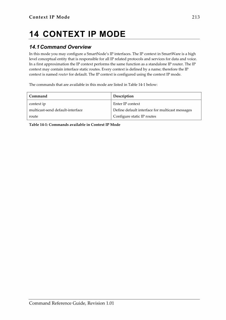
Context IP Mode 213
Command Reference Guide, Revision 1.01
14 CONTEXT IP MODE 14.1 Command Overview In this mode you may configure a SmartNode’s IP interfaces. The IP context in SmartWare is a high level conceptual entity that is responsible for all IP related protocols and services for data and voice. In a first approximation the IP context performs the same function as a standalone IP router. The IP context may contain interface static routes. Every context is defined by a name; therefore the IP context is named router for default. The IP context is configured using the context IP mode. The commands that are available in this mode are listed in Table 14-1 below:
Command Description
context ip multicast-send default-interface route
Enter IP context Define default interface for multicast messages Configure static IP routes
Table 14-1: Commands available in Context IP Mode
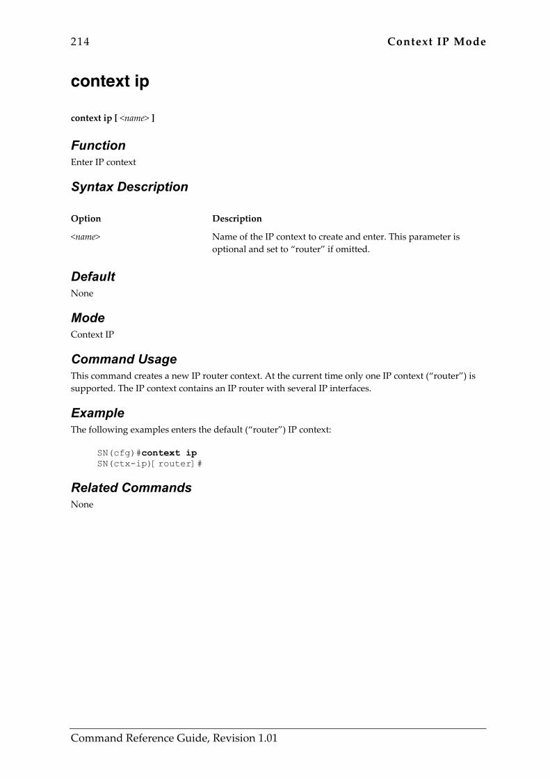
214 Context IP Mode
Command Reference Guide, Revision 1.01
context ip context ip [ <name> ]
Function Enter IP context
Syntax Description Option Description
<name> Name of the IP context to create and enter. This parameter is optional and set to “router” if omitted.
Default None
Mode Context IP
Command Usage This command creates a new IP router context. At the current time only one IP context (“router”) is supported. The IP context contains an IP router with several IP interfaces.
Example The following examples enters the default (“router”) IP context:
SN(cfg)#context ip SN(ctx-ip)[router]#
Related Commands None
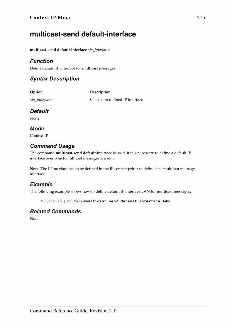
Context IP Mode 215
Command Reference Guide, Revision 1.01
multicast-send default-interface multicast-send default-interface <ip_interface>
Function Define default IP interface for multicast messages.
Syntax Description Option Description
<ip_interface> Select a predefined IP interface
Default None
Mode Context IP
Command Usage The command multicast-send default-interface is used, if it is necessary to define a default IP interface over which multicast messages are sent. Note: The IP interface has to be defined in the IP context priror to define it as multicast messages interface.
Example The following example shows how to define default IP interface LAN for multicast messages:
SN(ctx-ip)[router]#multicast-send default-interface LAN
Related Commands None

216 Context IP Mode
Command Reference Guide, Revision 1.01
route route <destaddr> <destmask> { <gwaddr> | <interface> } [ <metric> ]
Function Configure static IP routes
Syntax Description Option Description
<destaddr> The IP address of the target network or subnet
<destmask> A network mask where the 1 bits indicates the network, or subnet, and the 0 bits indicate the host portion of the network address provided
<gwaddr> The IP address of a next-hop router that can reach the target network or subnet
<interface> Name of the outgoing IP interface over which the target network or subnet is accessible
<metric> Specifies the desirability of the route when compared against other routes. The range is 0 through 15, where 0 is the preferred route
Default If no metric is specified, the static route is assumed to have a metric of 0.
Mode Context IP
Command Usage Once configured, a static route stays in the routing table indefinitely. When multiple static routes are configured for a single destination and the outbound interface of the current static route goes down, a backup route is activated. Each static route can be configured with a metric. The route with the lowest metric is the preferred route. A newly configured static route with a lower cost will override an existing static route that has a higher cost to the same destination. To configure a default static route use 0.0.0.0 for the network number and mask. A valid nex-hop address or interface is required. If static routes are redistributed through dynamic routing protocols, only the active static route to a destination is advertised. The no form of this command deletes a static route from the routing table.

Context IP Mode 217
Command Reference Guide, Revision 1.01
Example The following example packets to network 10.10.0.0/16 will be routed to the next-hop 10.10.0.1 with the default metric of 0:
SN(cfg)#context ip SN(ctx-ip)[router]#route 10.10.0.0 255.255.0.0 10.10.0.1
The next example estabishes a default route with metric 4 to the IP interface pvc1:
SN(cfg)#context ip SN(ctx-ip)[router]#route 0.0.0.0 0.0.0.0 pvc1 4
The next example removes the default route:
SN(cfg)#context ip SN(ctx-ip)[router]#no route 0.0.0.0 0.0.0.0 pvc1
Related Commands Command Description
show ip route Displays the active IP routing table.
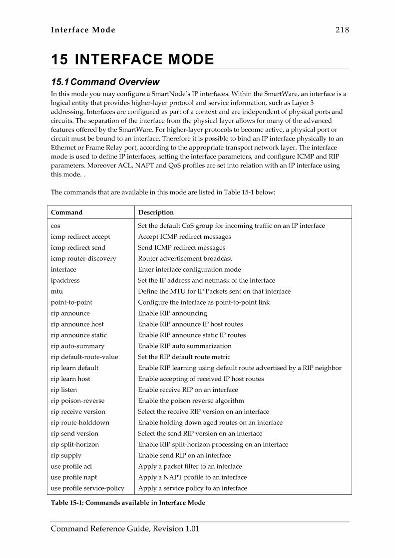
Interface Mode 218
Command Reference Guide, Revision 1.01
15 INTERFACE MODE 15.1 Command Overview In this mode you may configure a SmartNode’s IP interfaces. Within the SmartWare, an interface is a logical entity that provides higher-layer protocol and service information, such as Layer 3 addressing. Interfaces are configured as part of a context and are independent of physical ports and circuits. The separation of the interface from the physical layer allows for many of the advanced features offered by the SmartWare. For higher-layer protocols to become active, a physical port or circuit must be bound to an interface. Therefore it is possible to bind an IP interface physically to an Ethernet or Frame Relay port, according to the appropriate transport network layer. The interface mode is used to define IP interfaces, setting the interface parameters, and configure ICMP and RIP parameters. Moreover ACL, NAPT and QoS profiles are set into relation with an IP interface using this mode. . The commands that are available in this mode are listed in Table 15-1 below:
Command Description
cos icmp redirect accept icmp redirect send icmp router-discovery interface ipaddress mtu point-to-point rip announce rip announce host rip announce static rip auto-summary rip default-route-value rip learn default rip learn host rip listen rip poison-reverse rip receive version rip route-holddown rip send version rip split-horizon rip supply use profile acl use profile napt use profile service-policy
Set the default CoS group for incoming traffic on an IP interface Accept ICMP redirect messages Send ICMP redirect messages Router advertisement broadcast Enter interface configuration mode Set the IP address and netmask of the interface Define the MTU for IP Packets sent on that interface Configure the interface as point-to-point link Enable RIP announcing Enable RIP announce IP host routes Enable RIP announce static IP routes Enable RIP auto summarization Set the RIP default route metric Enable RIP learning using default route advertised by a RIP neighbor Enable accepting of received IP host routes Enable receive RIP on an interface Enable the poison reverse algorithm Select the receive RIP version on an interface Enable holding down aged routes on an interface Select the send RIP version on an interface Enable RIP split-horizon processing on an interface Enable send RIP on an interface Apply a packet filter to an interface Apply a NAPT profile to an interface Apply a service policy to an interface
Table 15-1: Commands available in Interface Mode

Interface Mode 219
Command Reference Guide, Revision 1.01
cos [no] cos <group>
Function Set the default CoS group for incoming traffic on an IP interface
Syntax Description Option Description
<group>
The name of a Class of Service (CoS) group.
Default None
Mode Interface
Command Usage By using this command it is possible to tag all incoming packets with a default CoS group. If the packet matches a rule in the access-list this rule can override the default CoS group. Use the no form of this command to remove the default CoS group from an IP interface.
Example Set default CoS group for incoming packets to WebTraffic. Packets that are not tagged by an access-list rule will be tagged WebTraffic.
SN(cfg)#context ip router SN(cfg-ip)[router]#interface eth0 SN(cfg-if)[eth0]#cos WebTraffic
Remove default CoS group from an interface.
SN(cfg)#context ip router SN(cfg-ip)[router]#interface eth0 SN(cfg-if)[eth0]#no cos
Related Commands Command Description
use profile acl Binds an access-list profile to an IP interface

220 Interface Mode
Command Reference Guide, Revision 1.01
icmp redirect accept icmp redirect accept
Function Accept ICMP redirect messages
Syntax Description Option Description
redirect accept
Host route redirects Accept ICMP redirect messages
Default Disabled
Mode Interface
Command Usage Dependent on the network architecture, it’s possible that a router resends a packet through the same interface on which it was received. If this happens, there is a more direct path for the packet’s originator for reaching the destination device. The router now can send an icmp redirect message to the sender, which instructs it to remove the receiving device from the route table and substitute it by the entry available in the redirect message. This command is used to permit the SmartWare to modify route entries based on a received icmp redirect message.
Example The following examples allows the router to accept icmp redirect messages:
SN(cfg)#context ip SN(ctx-ip)[router]#interface eth0 SN(if-ip)[eth0]#icmp redirect accept
Related Commands Command Description
icmp redirect send Allows the router to send icmp redirect messages
show ip interface Displays interface configuration and state
Interface Mode 221
Command Reference Guide, Revision 1.01
icmp redirect send [no] icmp redirect send
Function Send ICMP redirect messages
Syntax Description Option Description
redirect send
Host route redirects Send ICMP redirect messages
Default Enabled
Mode Interface
Command Usage Dependent on the network architecture, it’s possible that a router resends a packet through the same interface on which it was received. If this happens, there is a more direct path for the packet’s originator for reaching the destination device. The router now can send an icmp redirect message to the sender, which instructs it to remove the receiving device from the route table and substitute it by the entry available in the redirect message.
Example The following examples configures the router for sending icmp redirect messages:
SN(cfg)#context ip SN(ctx-ip)[router]#interface eth0 SN(if-ip)[eth0]#icmp redirect send
Related Commands Command Description
icmp redirect accept Allows the router to accept icmp redirect messages
show ip interface Displays interface configuration and state
222 Interface Mode
Command Reference Guide, Revision 1.01
icmp router-discovery icmp router-discovery
Function Enable or disable router advertisement broadcasts
Syntax Description Option Description
This command has no keywords or options
Default Enabled
Mode Interface
Command Usage The ICMP Router Discovery Protocol uses Router-Advertisement and Router-Solicitation messages to discover the addresses of routers on directly attached subnets. By default, this feature is enabled, so ICMP router advertisement messages are sent either as a reply of an ICMP router solicitation message or periodically.
Example The following example disables the ICMP Router Discovery protocol fot the interface eth0:
SN(cfg)#context ip SN(ctx-ip)[router]#interface eth0 SN(if-ip)[eth0]#no icmp router-discovery
Related Commands Command Description
show ip interface Displays interface configuration and state
Interface Mode 223
Command Reference Guide, Revision 1.01
interface [no] interface <name>
Function Enter interface configuration mode
Syntax Description Option Description
<name> Name of the IP interface
Default None
Mode Context IP
Command Usage If the interface with the specified name doesn’t exist, a new interface will be created. This command creates only a logical interface, so it has no connection to a physical circuit. For enabling ip processing on this interface, an active link layer circuit must be bound to this interface. If the interface already exists, the command enters the configuration mode of the specified interface. The no prefix removes an existing interface. An interface can only be removed, if it has no active binding.
Example The following example creates a new interface under the name ‘eth0’ and enters the interface configuration mode:
SN(ctx-ip)#interface eth0 SN(if-ip)[eth0]#
The following example removes the interface with the name ‘eth0’ and enters Context Ip configuration mode:
SN(if-ip)[eth0]#no interface eth0 SN(ctx-ip)
Related Commands Command Description
context ip [router ] Enters IP context
show ip interface Displays interface configuration and state

224 Interface Mode
Command Reference Guide, Revision 1.01
ipaddress Configures or changes the ipaddress of an interface
Interface Mode 225
Command Reference Guide, Revision 1.01
ipaddress ipaddress { unnumbered | ( <ip_address> <ip_mask> ) }
Function Set the IP address and netmask of the interface
Syntax Description Option Description
unnumbered Enables ip processsing on an interface without assigning an explicit ip address to the interface.
<ip_address> Specifies the ip address of the interface in the form A.B.C.D
<ip_mask> Specifies the netmask of the interface
Default None
Mode Interface
Command Usage For enabling ip processing on an interface, it uses a valid host interface configuration. That means every active ip interface connected to a network segment must belong to a unique subnet. The command checks, if the parameters entered by the user meet this requirements. Entering an ip address and a netmask if the interface needs its own ip address and has to be connected to a specified subnet. If the interface is configured as point-to-point where only one remote peer is available, it maybe doesn’t make sense to configure a subnet containing address spaces can be used for other interfaces. In this case, there is the possibility to configure the interface as unnumbered link, which uses the ip address of the first interface gets a valid host interface address. An interface configured as unnumbered is not visible in the routing table if the command show ip route will be executed. But the router has knowledge about this interface and so it’s possible to configure a static route using this interface.
Example The following example enters interface configuration mode and configures a valid ip address and netmask for a B-Class subnet:
SN(ctx-ip)#interface pvc100 SN(if-ip)[pvc100]#ipaddress 172.16.8.88 255.255.0.0
The following example configures the interface as point-to-point unnumbered link and sets a static route to the remote peer:

226 Interface Mode
Command Reference Guide, Revision 1.01
SN(if-ip)[pvc100]#point-to-point SN(if-ip)[pvc100]#ipaddress unnumbered SN(if-ip)[pvc100]#exit SN(ctx-ip)#route 172.17.50.10 255.255.255.255 pvc100
Related Commands Command Description
point-to-point Configures interface as point to point link
route Adds a new static route to the routing table
show ip route Dispalys the routing table
Interface Mode 227
Command Reference Guide, Revision 1.01
mtu mtu <mtu>
Function Define the maximum transmission unit (MTU) for IP Packets sent on that interface
Syntax Description Option Description
<mtu> Maximum IP Transmission Unit in bytes. The range is 68 thrgouth 1500 Byte
Default The MTU is set to 1500 bytes by default.
Mode Interface
Command Usage If an Ip Packet exceeds the MTU configured on that interface, the router will fragment that packet.
Example The following example configures a new MTU for an existing interface:
SN(ctx-ip)#interface test SN(if-ip)[test]#mtu 812
Related Commands Command Description
show ip interface Displays interface configuration and state
228 Interface Mode
Command Reference Guide, Revision 1.01
point-to-point point-to-point
Function Configure the interface as point-to-point link
Syntax Description Option Description
This command has no keywords or options
Default By default an interface is not configured as point-to-point link.
Mode Interface
Command Usage Configure point-to-point on every interface, which has only one remote peer on its data link. If point-to-point will be disabled by the no prefix, nothing will be printed out in the running configuration.
Example The following example configures an interface as point-to-point link that will be bound to a framerelay pvc:
SN(ctx-ip)#interface pvc100 SN(if-ip)[pvc100]#point-to-point
Related Commands None
Interface Mode 229
Command Reference Guide, Revision 1.01
rip announce rip announce { default | self-as-default }
Function Configures RIP default-route announcing
Syntax Description Option Description
default Enables or disables announcing the RIP default route out the current interface
self-as-default Enables or disables that the current interface’s IP address is announced as default gateway
Default The IP interface does not send default routes if not configured.
Mode Interface
Command Usage This command configures whether or not the interface sends a default route in RIP messages. When setting the parameter to default, the interface sends the default route in the routing table out this interface. When setting this parameter to self-as-default, the interface sends its own IP interface address as default route destination. Both parameters cannot be set at the same time.
Example The following enables RIP on the interface eth1 and sends the default route of the router:
SN(cfg)#context ip SN(ctx-ip)[router]#interface eth1 SN(if-ip)[eth1]#rip supply SN(if-ip)[eth1]#rip announce default
The next example enables RIP on the interface eth1 and sends the own interface’s IP address as default route destination:
SN(cfg)#context ip SN(ctx-ip)[router]#interface eth1 SN(if-ip)[eth1]#rip supply SN(if-ip)[eth1]#rip announce self-as-default
Related Commands Command Description
230 Interface Mode
Command Reference Guide, Revision 1.01
rip announce rip announce host rip announce static rip auto-summary rip default-route-value rip learn default rip learn host rip listen rip poison-reverse rip receive version rip route-holddown rip send version rip split-horizon rip supply
Enable RIP announcing Enable RIP announce IP host routes Enable RIP announce static IP routes Enable RIP auto summarization Set the RIP default route metric Enable RIP learning using default route advertised by a RIP neighbor Enable accepting of received IP host routes Enable receive RIP on an interface Enable the poison reverse algorithm Select the receive RIP version on an interface Enable holding down aged routes on an interface Select the send RIP version on an interface Enable RIP split-horizon processing on an interface Enable send RIP on an interface
Interface Mode 231
Command Reference Guide, Revision 1.01
rip announce host rip announce host
Function Enable RIP announce IP host routes
Syntax Description Option Description
This command has no keywords or options
Default The IP interface does not send host routes if not configured.
Mode Interface
Command Usage This command enables the transmission of IP host routes in RIP messages sent from this interface. The no form disables the transmission of IP host routes in RIP messages.
Example The following example enables the transmission of RIP host routes on the IP interface eth1:
SN(cfg)#context ip SN(ctx-ip)[router]#interface eth1 SN(if-ip)[eth1]#rip announce host
The next example disables the transmission of RIP host routes on the IP interface eth1:
SN(cfg)#context ip SN(ctx-ip)[router]#interface eth1 SN(if-ip)[eth1]#no rip announce host
Related Commands Command Description
rip announce rip announce host rip announce static rip auto-summary rip default-route-value rip learn default
Enable RIP announcing Enable RIP announce IP host routes Enable RIP announce static IP routes Enable RIP auto summarization Set the RIP default route metric Enable RIP learning using default route advertised by a RIP neighbor

232 Interface Mode
Command Reference Guide, Revision 1.01
rip learn host rip listen rip poison-reverse rip receive version rip route-holddown rip send version rip split-horizon rip supply
Enable accepting of received IP host routes Enable receive RIP on an interface Enable the poison reverse algorithm Select the receive RIP version on an interface Enable holding down aged routes on an interface Select the send RIP version on an interface Enable RIP split-horizon processing on an interface Enable send RIP on an interface
Interface Mode 233
Command Reference Guide, Revision 1.01
rip announce static rip announce static
Function Enable RIP announce static IP routes
Syntax Description Option Description
This command has no keywords or options
Default The IP interface does not send default routes if not configured.
Mode Interface
Command Usage This command enables the transmission of static IP routes in RIP messages sent from this interface. The no form disables the transmission of static IP routes in RIP messages.
Example The following example enables the transmission of RIP static routes on the IP interface eth1:
SN(cfg)#context ip SN(ctx-ip)[router]#interface eth1 SN(if-ip)[eth1]#rip announce static
The next example disables the transmission of RIP static routes on the IP interface eth1:
SN(cfg)#context ip SN(ctx-ip)[router]#interface eth1 SN(if-ip)[eth1]#no rip announce static
Related Commands Command Description
rip announce rip announce host rip announce static rip auto-summary rip default-route-value rip learn default
Enable RIP announcing Enable RIP announce IP host routes Enable RIP announce static IP routes Enable RIP auto summarization Set the RIP default route metric Enable RIP learning using default route advertised by a RIP neighbor

234 Interface Mode
Command Reference Guide, Revision 1.01
rip learn host rip listen rip poison-reverse rip receive version rip route-holddown rip send version rip split-horizon rip supply
Enable accepting of received IP host routes Enable receive RIP on an interface Enable the poison reverse algorithm Select the receive RIP version on an interface Enable holding down aged routes on an interface Select the send RIP version on an interface Enable RIP split-horizon processing on an interface Enable send RIP on an interface
Interface Mode 235
Command Reference Guide, Revision 1.01
rip auto-summary rip auto-summary
Function Enable RIP auto summarization
Syntax Description Option Description
This command has no keywords or options
Default Auto-summarization is off per default.
Mode Interface
Command Usage Enables the generation of route summaries in RIP responses sent out the current IP interface. Route summarization consists of announcing only the parent network address of IP subnets to other IP networks.
Example The following example enables RIP route summarization on the IP interface eth1:
SN(cfg)#context ip SN(ctx-ip)[router]#interface eth1 SN(if-ip)[eth1]#rip auto-summary
The next example disables RIP route summarization on the IP interface eth1:
SN(cfg)#context ip SN(ctx-ip)[router]#interface eth1 SN(if-ip)[eth1]#no rip auto-summary
Related Commands Command Description
rip announce rip announce host rip announce static rip auto-summary rip default-route-value
Enable RIP announcing Enable RIP announce IP host routes Enable RIP announce static IP routes Enable RIP auto summarization Set the RIP default route metric

236 Interface Mode
Command Reference Guide, Revision 1.01
rip learn default rip learn host rip listen rip poison-reverse rip receive version rip route-holddown rip send version rip split-horizon rip supply
Enable RIP learning using default route advertised by a RIP neighbor Enable accepting of received IP host routes Enable receive RIP on an interface Enable the poison reverse algorithm Select the receive RIP version on an interface Enable holding down aged routes on an interface Select the send RIP version on an interface Enable RIP split-horizon processing on an interface Enable send RIP on an interface
Interface Mode 237
Command Reference Guide, Revision 1.01
rip default-route-value rip default-route-value <metric>
Function Set the RIP default route metric
Syntax Description Option Description
<metric> Number indicating the distance to the destination for default routes.
Default No metric is specified, which lets RIP send the metric 0 for default routes.
Mode Interface
Command Usage This command is used to specify a metric that is used to send default routes with.
Example The following example enables RIP default route metric overriding on the IP interface eth1:
SN(cfg)#context ip SN(ctx-ip)[router]#interface eth1 SN(if-ip)[eth1]#rip default-route-value 5
The next example disables RIP default route metric overriding on the IP interface eth1:
SN(cfg)#context ip SN(ctx-ip)[router]#interface eth1 SN(if-ip)[eth1]#no rip default-route-value
Related Commands Command Description
rip announce rip announce host rip announce static rip auto-summary rip default-route-value rip learn default rip learn host
Enable RIP announcing Enable RIP announce IP host routes Enable RIP announce static IP routes Enable RIP auto summarization Set the RIP default route metric Enable RIP learning using default route advertised by a RIP neighbor Enable accepting of received IP host routes

238 Interface Mode
Command Reference Guide, Revision 1.01
rip listen rip poison-reverse rip receive version rip route-holddown rip send version rip split-horizon rip supply
Enable receive RIP on an interface Enable the poison reverse algorithm Select the receive RIP version on an interface Enable holding down aged routes on an interface Select the send RIP version on an interface Enable RIP split-horizon processing on an interface Enable send RIP on an interface

Interface Mode 239
Command Reference Guide, Revision 1.01
rip learn default [no] rip learn default
Function Enable RIP learning using default route advertised by a RIP neighbor
Syntax Description Option Description
This command has no keywords or options
Default The IP interface does not learn default routes if not configured.
Mode Interface
Command Usage Enables the learning and using a default route advertised by a RIP neighbour. The no form disables the learning of default routes.
Example The following example enables the reception of RIP default routes on the IP interface eth1:
SN(cfg)#context ip SN(ctx-ip)[router]#interface eth1 SN(if-ip)[eth1]#rip learn default
The next example disables the reception of RIP default routes on the IP interface eth1:
SN(cfg)#context ip SN(ctx-ip)[router]#interface eth1 SN(if-ip)[eth1]#no rip learn default
Related Commands Command Description
rip announce rip announce host rip announce static rip auto-summary rip default-route-value rip learn default
Enable RIP announcing Enable RIP announce IP host routes Enable RIP announce static IP routes Enable RIP auto summarization Set the RIP default route metric Enable RIP learning using default route advertised by a RIP neighbor

240 Interface Mode
Command Reference Guide, Revision 1.01
rip learn host rip listen rip poison-reverse rip receive version rip route-holddown rip send version rip split-horizon rip supply
Enable accepting of received IP host routes Enable receive RIP on an interface Enable the poison reverse algorithm Select the receive RIP version on an interface Enable holding down aged routes on an interface Select the send RIP version on an interface Enable RIP split-horizon processing on an interface Enable send RIP on an interface
Interface Mode 241
Command Reference Guide, Revision 1.01
rip learn host [no] rip learn host
Function Enable accepting of received IP host routes
Syntax Description Option Description
This command has no keywords or options
Default The IP interface does not learn host routes if not configured.
Mode Interface
Command Usage Enables the learning and using a host route advertised by a RIP neighbour. The no form disables the learning of host routes.
Example The following example enables the reception of RIP host routes on the IP interface eth1:
SN(cfg)#context ip SN(ctx-ip)[router]#interface eth1 SN(if-ip)[eth1]#rip learn host
The next example disables the reception of RIP host routes on the IP interface eth1:
SN(cfg)#context ip SN(ctx-ip)[router]#interface eth1 SN(if-ip)[eth1]#no rip learn host
Related Commands Command Description
rip announce rip announce host rip announce static rip auto-summary rip default-route-value rip learn default
Enable RIP announcing Enable RIP announce IP host routes Enable RIP announce static IP routes Enable RIP auto summarization Set the RIP default route metric Enable RIP learning using default route advertised by a RIP neighbor

242 Interface Mode
Command Reference Guide, Revision 1.01
rip learn host rip listen rip poison-reverse rip receive version rip route-holddown rip send version rip split-horizon rip supply
Enable accepting of received IP host routes Enable receive RIP on an interface Enable the poison reverse algorithm Select the receive RIP version on an interface Enable holding down aged routes on an interface Select the send RIP version on an interface Enable RIP split-horizon processing on an interface Enable send RIP on an interface
Interface Mode 243
Command Reference Guide, Revision 1.01
rip listen [no] rip listen
Function Enable receive RIP on an interface
Syntax Description Option Description
This command has no keywords or options
Default The IP interface does not receives RIP messages if not configured.
Mode Interface
Command Usage This command enables the reception of RIP messages on the current interface. All RIP learn sub-commands have no effect before listening is not enabled. The no form disables the reception of RIP messages on the current interface.
Example The following example enables the reception of RIP messages on the IP interface eth1:
SN(cfg)#context ip SN(ctx-ip)[router]#interface eth1 SN(if-ip)[eth1]#rip listen
The next example disables the reception of RIP messages no the IP interface eth1:
SN(cfg)#context ip SN(ctx-ip)[router]#interface eth1 SN(if-ip)[eth1]#no rip listen
Related Commands Command Description
rip announce rip announce host rip announce static rip auto-summary rip default-route-value
Enable RIP announcing Enable RIP announce IP host routes Enable RIP announce static IP routes Enable RIP auto summarization Set the RIP default route metric

244 Interface Mode
Command Reference Guide, Revision 1.01
rip learn default rip learn host rip listen rip poison-reverse rip receive version rip route-holddown rip send version rip split-horizon rip supply
Enable RIP learning using default route advertised by a RIP neighbor Enable accepting of received IP host routes Enable receive RIP on an interface Enable the poison reverse algorithm Select the receive RIP version on an interface Enable holding down aged routes on an interface Select the send RIP version on an interface Enable RIP split-horizon processing on an interface Enable send RIP on an interface
Interface Mode 245
Command Reference Guide, Revision 1.01
rip poison-reverse [no] rip poison-reverse
Function Enable the poison reverse algorithm
Syntax Description Option Description
This command has no keywords or options
Default The poison-reverse algorithm is off per default.
Mode Interface
Command Usage This command enables the use of the poison reverse algorithm to RIP routes being advertised on the current IP interface. When enabling the split horizon algorithm on the current interface, the interface does not send out learned entries onto the network or to the neighbour to which they were learned. When additionally enabling poison-reverse, that entries are sent with a metric of 16, which is infinite.
Example The following example shows how to enable split-horizon with poison-reverse on the IP interface eth1:
SN(cfg)#context ip SN(ctx-ip)[router]#interface eth1 SN(if-ip)[eth1]#rip split-horizon SN(if-ip)[eth1]#rip poison-reverse
Related Commands Command Description
rip announce rip announce host rip announce static rip auto-summary rip default-route-value rip learn default rip learn host
Enable RIP announcing Enable RIP announce IP host routes Enable RIP announce static IP routes Enable RIP auto summarization Set the RIP default route metric Enable RIP learning using default route advertised by a RIP neighbor Enable accepting of received IP host routes

246 Interface Mode
Command Reference Guide, Revision 1.01
rip listen rip poison-reverse rip receive version rip route-holddown rip send version rip split-horizon rip supply
Enable receive RIP on an interface Enable the poison reverse algorithm Select the receive RIP version on an interface Enable holding down aged routes on an interface Select the send RIP version on an interface Enable RIP split-horizon processing on an interface Enable send RIP on an interface

Interface Mode 247
Command Reference Guide, Revision 1.01
rip receive version rip receive version { 1 | 2 | 1or2 }
Function Select the receive RIP version on an interface
Syntax Description Option Description
1 2 1or2
Accept RIP version 1 packets on the current interface Accept RIP version 2 packets on the current interface Accept RIP version 1 or 2 packets on the current interface
Default The default setting is to accept version 1 or 2 packets on the current interface.
Mode Interface
Command Usage Use this command to specify RIP packets of which protocol version shall be accepted on the current interface. RIP v1 is a simple distance vector protocol. It has been enhanced with Split Horizon and Poison Reverse in order to enable it to perform better in somewhat complicated networks. RIP v2 adds several new features like authentication and multicast support.
Example The following example shows how to enable receving only RIP v1 packets on the IP interface eth0:
SN(cfg)#context ip SN(ctx-ip)[router]#interface eth1 SN(if-ip)[eth1]#rip listen SN(if-ip)[eth1]#rip receive version 1
The next example resets the RIP receive processor to the default setting. RIP v1 and v2 packets are received by the interface.
SN(if-ip)[eth1]#rip receive version 1or2
Related Commands Command Description
rip announce rip announce host rip announce static
Enable RIP announcing Enable RIP announce IP host routes Enable RIP announce static IP routes
248 Interface Mode
Command Reference Guide, Revision 1.01
rip auto-summary rip default-route-value rip learn default rip learn host rip listen rip poison-reverse rip receive version rip route-holddown rip send version rip split-horizon rip supply
Enable RIP auto summarization Set the RIP default route metric Enable RIP learning using default route advertised by a RIP neighbor Enable accepting of received IP host routes Enable receive RIP on an interface Enable the poison reverse algorithm Select the receive RIP version on an interface Enable holding down aged routes on an interface Select the send RIP version on an interface Enable RIP split-horizon processing on an interface Enable send RIP on an interface
Interface Mode 249
Command Reference Guide, Revision 1.01
rip route-holddown [no] rip route-holddown
Function Enable holding down aged routes on an interface
Syntax Description Option Description
This command has no keywords or options
Default None
Mode Interface
Command Usage Enables holding down (i.e. locking) aged routes learned from RIP messages on the current IP interface. Thus an aged route cannot be refreshed to a non-aged status but must instead be deleted and then relearned, thus enhancing the stability of the RIP topology in the presence of transients. The no form disables holding down aged routes.
Example The following examples enables route-holddown on the IP interface eth1:
SN(cfg)#context ip SN(ctx-ip)[router]#interface eth1 SN(if-ip)[eth1]#rip route-holddown
Related Commands Command Description
rip announce rip announce host rip announce static rip auto-summary rip default-route-value rip learn default rip learn host rip listen rip poison-reverse
Enable RIP announcing Enable RIP announce IP host routes Enable RIP announce static IP routes Enable RIP auto summarization Set the RIP default route metric Enable RIP learning using default route advertised by a RIP neighbor Enable accepting of received IP host routes Enable receive RIP on an interface Enable the poison reverse algorithm

250 Interface Mode
Command Reference Guide, Revision 1.01
rip receive version rip route-holddown rip send version rip split-horizon rip supply
Select the receive RIP version on an interface Enable holding down aged routes on an interface Select the send RIP version on an interface Enable RIP split-horizon processing on an interface Enable send RIP on an interface

Interface Mode 251
Command Reference Guide, Revision 1.01
rip send version rip send version { 1 | 2 | 1compatible }
Function Select the send RIP version on an interface
Syntax Description Option Description
1 2 1compatible
Send RIP version 1 packets on the current interface Send RIP version 2 packets on the current interface Send RIP version 1 compatible on the current interface
Default The interface sends version 1 compatible RIP messages on the current interface if not configured differently.
Mode Interface
Command Usage This command configures the RIP version of packets that are sent out the current IP interface. Version 1 only sends RIP v1 messages. Version 2 sends multicast RIP v2 messages. Version 1 compatible sends broadcast RIP v2 messages.
Example The following example shows how to send only RIP v1 messages out the IP interface eth1:
SN(cfg)#context ip SN(ctx-ip)[router]#interface eth1 SN(if-ip)[eth1]#rip send version 1
Related Commands Command Description
rip announce rip announce host rip announce static rip auto-summary rip default-route-value rip learn default rip learn host
Enable RIP announcing Enable RIP announce IP host routes Enable RIP announce static IP routes Enable RIP auto summarization Set the RIP default route metric Enable RIP learning using default route advertised by a RIP neighbor Enable accepting of received IP host routes

252 Interface Mode
Command Reference Guide, Revision 1.01
rip listen rip poison-reverse rip receive version rip route-holddown rip send version rip split-horizon rip supply
Enable receive RIP on an interface Enable the poison reverse algorithm Select the receive RIP version on an interface Enable holding down aged routes on an interface Select the send RIP version on an interface Enable RIP split-horizon processing on an interface Enable send RIP on an interface
Interface Mode 253
Command Reference Guide, Revision 1.01
rip split-horizon [no] rip split-horizon
Function Enable RIP split-horizon processing on an interface
Syntax Description Option Description
This command has no keywords or options
Default None
Mode Interface
Command Usage This command enables the use of the split horizon algorithm to RIP routes being advertised on the current IP interface. When enabling the split horizon algorithm on the current interface, the interface does not send out learned entries onto the network or to the neighbour to which they were learned. When additionally enabling poison-reverse, that entries are sent with a metric of 16, which is infinite.
Example The following example shows how to enable split-horizon with poison-reverse on the IP interface eth1:
SN(cfg)#context ip SN(ctx-ip)[router]#interface eth1 SN(if-ip)[eth1]#rip split-horizon SN(if-ip)[eth1]#rip poison-reverse
Related Commands Command Description
rip announce rip announce host rip announce static rip auto-summary rip default-route-value rip learn default rip learn host
Enable RIP announcing Enable RIP announce IP host routes Enable RIP announce static IP routes Enable RIP auto summarization Set the RIP default route metric Enable RIP learning using default route advertised by a RIP neighbor Enable accepting of received IP host routes

254 Interface Mode
Command Reference Guide, Revision 1.01
rip listen rip poison-reverse rip receive version rip route-holddown rip send version rip split-horizon rip supply
Enable receive RIP on an interface Enable the poison reverse algorithm Select the receive RIP version on an interface Enable holding down aged routes on an interface Select the send RIP version on an interface Enable RIP split-horizon processing on an interface Enable send RIP on an interface
Interface Mode 255
Command Reference Guide, Revision 1.01
rip supply [no] rip supply
Function Enable send RIP on an interface
Syntax Description Option Description
This command has no keywords or options
Default The IP interface does not send RIP messages if not configured.
Mode Interface
Command Usage This command enables the transmission of RIP messages on the current interface. All RIP announce sub-commands have no effect before supplying is not enabled. The no form disables the transmission of RIP messages on the current interface.
Example The following example enables the transmission of RIP messages on the IP interface eth1:
SN(cfg)#context ip SN(ctx-ip)[router]#interface eth1 SN(if-ip)[eth1]#rip supply
The next example disables the transmission of RIP messages no the IP interface eth1:
SN(cfg)#context ip SN(ctx-ip)[router]#interface eth1 SN(if-ip)[eth1]#no rip supply
Related Commands Command Description
rip announce rip announce host rip announce static rip auto-summary rip default-route-value
Enable RIP announcing Enable RIP announce IP host routes Enable RIP announce static IP routes Enable RIP auto summarization Set the RIP default route metric

256 Interface Mode
Command Reference Guide, Revision 1.01
rip learn default rip learn host rip listen rip poison-reverse rip receive version rip route-holddown rip send version rip split-horizon rip supply
Enable RIP learning using default route advertised by a RIP neighbor Enable accepting of received IP host routes Enable receive RIP on an interface Enable the poison reverse algorithm Select the receive RIP version on an interface Enable holding down aged routes on an interface Select the send RIP version on an interface Enable RIP split-horizon processing on an interface Enable send RIP on an interface
Interface Mode 257
Command Reference Guide, Revision 1.01
use profile acl [no] use profile acl <name> { in | out }
Function Apply a packet filter to an interface
Syntax Description Option Description
profile Applies a profile to this interface
acl Applies a packet filter to this interface
<name> The name of an access-list profile that has already been created using the profile acl command. This argument must be omitted in the no form.
in Specifies that the access-list profile applies to incoming packets on this interface.
out Specifies that the access-list profile applies to outgoing packets on this interface.
Default None
Mode Interface
Command Usage Binds an access-list profile to an IP interface. Use the no form of this command to remove an access-list profile from an IP interface.
Example Apply an access-list profile to incoming packets on interface eth0 in the router context.
SN(cfg)#context ip router SN(cfg-ip)[router]#interface eth0 SN(cfg-if)[eth0]#use profile acl WanRx in SN(cfg-if)[eth0]#
Remove an access-list profile from an interface. Please note that the no form does not require the <name> argument.
SN(cfg-if)[eth0]#no use profile acl in

258 Interface Mode
Command Reference Guide, Revision 1.01
Related Commands Command Description
profile acl Creates an IP access-list profile
Interface Mode 259
Command Reference Guide, Revision 1.01
use profile napt [no] use profile napt <name>
Function Apply a NAPT profile to an interface
Syntax Description Option Description
<name> Name of the NAPT profile to apply.
Default No NAPT profile is applied per default.
Mode Interface
Command Usage This command is used to apply a NAPT profile to the current IP interface. Once applied, the IP interface is the global NAPT interface and all other interfaces are local NAPT interfaces. Thus only one NAPT profile can be applied to only one interface.
Example The following example applies the NAPT profile “global” to the IP interface eth0, which gets the global interface:
SN(cfg)#context ip SN(ctx-ip)[router]#interface eth1 SN(if-ip)[eth1]#use profile napt global
Related Commands Command Description
profile napt Creates/Configures a NAPT profile
show profile napt Displays a NAPT profile
show interface napt Displays the NAPT profile usage of an interface
260 Interface Mode
Command Reference Guide, Revision 1.01
use profile service-policy [no] use profile service-policy <arbiter-name> { in | out }
Function Apply a service policy to an interface
Syntax Description Option Description
profile service-policy <arbiter-name> in out
Applies a service policy profile to this interface Name of the profile Receive direction Transmit direction
Default The default setting “no service-policy” sets the interface to FIFO queuing.
Mode Interface
Command Usage Any service policy profile needs to be bound to a certain IP interface to get activated. According the terminology of SmartWare a service policy profile is used on a certain IP interface. Therefore the use profile service-policy command allows attaching a certain service policy profile to an IP interface that is defined within the IP context. The command offers an optional argument allowing to define that the service policy profile is activated in receive or transmit direction. Note: Be aware that service policy profiles can only be activated on the transmit direction at the moment! Providers may use input shaping to improve downlink voice jitter in the absence of voice support.
Example The following example shows how to attach the service policy profile Voice_Prio to the IP interface wan that is defined within the IP context for outgoing traffic.
SN>enable SN#configure SN(cfg)#context ip router SN(ctx-ip)[router]#interface wan SN(if-ip)[wan]#use profile service-policy Voice_Prio out
Related Commands None
Context CS Mode 261
Command Reference Guide, Revision 1.01
16 CONTEXT CS MODE 16.1 Command Overview In this mode you may configure a node’s Circuit Switching, creating, editing or deleting routing table entries. The CS context in SmartWare is a high level conceptual entity that is responsible for all aspects of circuit signalling, switching and emulation. The CS entity comprises the Context CS itself, CS Interfaces, ISDN Ports, Tone-Set Profiles, ISoIP and H.323 Gateways and VoIP Profiles. The context CS mode is used to configure call routing, create number manipulation functions, and defining other call related behavior. Calls through a SmartNode can be routed according to a set of routing criteria. The entity that manages call routing is called Session Router. Calls are routed from one CS interface to another. The Session Router determines the destination interface for every incoming call. It supports complex call routing and number manipulation functions. The commands that are available in this mode are listed in Table 16-1 below:
Command Description
bearer-capability called-party calling-party complex-function context cs date delete number-manipulation number-prefix shutdown time translation-table use tone-set-profile weekday
Add an entry to a bearer-capability routing table Add an entry to a called party number routing table Create a function used witin a complex function Add an entry to a date routing table Enter session-router configuration mode Add an entry to a date routing table Delete a session router element Create an E.164 number manipulation function Define a number prefix Shutdown circuit context and reload entire session-router configuration Add an entry to a time routing table Add entry to number translation table Link to a tone profile Add an entry to a weekday routing table
Table 16-1: Commands available in Context CS Mode
262 Context CS Mode
Command Reference Guide, Revision 1.01
bearer-capability [no] bearer-capability <name> {audio31 | audio71 | rd | speech | ud | video | default } ( { ( { ( dest-table <dest-name> ) | ( dest-interface <dest-name> ) } [ <func> ] ) | none } )
Function Add an entry to a bearer-capability routing table
Syntax Description Option Description
<name> audio31 audio71 rd speech ud video default dest-table <dest-name> dest-interface <dest-name> <func> none
Table name Audio at 3.1 kHz Audio at 7.1 kHz Restricted digital information Speech Unristricted digital information Video Default entry to be used, if no other key matches Use routing table as destination Table name Use interface as destination Interface name Function to be executed Drop session
Default None
Mode Context CS
Command Usage This command is used to add an entry to a bearer-capability routing table. If the table does not already exist, it will be created.
Example The following example shows how to add an entry to a bearer-capability table named ‘rt’, which routes all speech calls to the voice interface ‘vif’ and executes function ‘func’ before jumping to the interface:
SN(ctx-cs)[switch]#bearer-capability rt speech dest-interface vif func
Context CS Mode 263
Command Reference Guide, Revision 1.01
The next example shows how to delete the entire routing table named rt:
SN(ctx-cs)[switch]#no bearer-capability rt
Related Commands Command Description
called-party Creates/adds called-party number routing tables/entries.
calling-party Creates/adds calling-party number routing tables/entries.
date Creates/adds date routing tables/entries.
time Creates/adds time-of-day routing tables/entries.
weekday Creates/adds day-of-week routing tables/entries.
264 Context CS Mode
Command Reference Guide, Revision 1.01
called-party [no] called-party <name> <key> ( { ( { ( dest-table <dest-name> ) | ( dest-interface <dest-name> ) } [ <func> ] ) | none } )
Function Add an entry to a called party number routing table
Syntax Description Option Description
<name> <key> dest-table <dest-name> dest-interface <dest-name> <func> none
Table name Key of entry (E.164 number or 'default') Use routing table as destination Table name Use interface as destination Interface name Function to be executed Drop session
Default None
Mode Context CS
Command Usage This command is used to add an entry to a called-party routing table. If the table does not already exist, it will be created.
Example The following example shows how to add an entry to a bearer-capability table named ‘rt1’, which routes all speech calls to the routing table ‘rt2’ and executes function ‘func1’ before jumping to the table:
SN(ctx-cs)[switch]#called-party rt1 dest-table rt2 func1 The next example shows how to delete the entire routing table named rt1:
SN(ctx-cs)[switch]#no called-party rt
Related Commands Command Description

Context CS Mode 265
Command Reference Guide, Revision 1.01
bearer-capability Creates/bearer-capability number routing tables/entries.
calling-party Creates/adds calling-party number routing tables/entries.
date Creates/adds date routing tables/entries.
time Creates/adds time-of-day routing tables/entries.
weekday Creates/adds day-of-week routing tables/entries.
266 Context CS Mode
Command Reference Guide, Revision 1.01
calling-party [no] calling-party <name> <key> ( { ( { ( dest-table <dest-name> ) | ( dest-interface <dest-name> ) } [ <func> ] ) | none } )
Function Add an entry to a calling party number routing table
Syntax Description Option Description
<name> <key> dest-table <dest-name> dest-interface <dest-name> <func> none
Table name Key of entry (E.164 number or 'default') Use routing table as destination Table name Use interface as destination Interface name Function to be executed Drop session
Default None
Mode Context CS
Command Usage This command is used to add an entry to a calling-party routing table. If the table does not already exist, it will be created.
Example The following example shows how to add an entry to a calling-party table named ‘rt’, which routes all calls from subscriber 0319123432 to the voice interface ‘vif’ and executes function ‘func’ before jumping to the interface:
SN(ctx-cs)[switch]#calling-party rt 0319123432 dest-interface vif func
The next example shows how to delete the entire routing table named rt:
SN(ctx-cs)[switch]#no calling-party rt
Related Commands Command Description

Context CS Mode 267
Command Reference Guide, Revision 1.01
bearer-capability Creates/adds bearer-capability number routing tables/entries.
called-party Creates/adds called-party number routing tables/entries.
date Creates/adds date routing tables/entries.
time Creates/adds time-of-day routing tables/entries.
weekday Creates/adds day-of-week routing tables/entries.
268 Context CS Mode
Command Reference Guide, Revision 1.01
complex-function [no] complex-function <name> <param>
Function Create a function used witin a complex function
Syntax Description Option Description
<name> <param>
Function name Function to be called
Default None
Mode Context CS
Command Usage Complex-functions are used, whenever a function in a routing table needs to do more than one single operation. For example, if the function should add digits to the called and calling party number. A complex-function is actually a list of normal session-router functions, which will be executed sequentially.
Example The following example creates a complex function named comfunc, which executes func1, func2 and func3 sequentially:
SN(ctx-cs)[switch]#complex-function comfunc func1 SN(ctx-cs)[switch]#complex-function comfunc func2 SN(ctx-cs)[switch]#complex-function comfunc func3
The next example deletes the complex function comfunc
SN(ctx-cs)[switch]#complex-function comfunc
Related Commands None
Context CS Mode 269
Command Reference Guide, Revision 1.01
context cs [no] context cs [ <name> ]
Function Enter session-router configuration mode
Syntax Description Option Description
<name> Name of the circuit context to enter
Default None
Mode Context CS
Command Usage This command is used to enter the circuit context configuration mode. In this mode, all session-router configuration is done.
Example The following example shows the usage:
SN(cfg)#context cs SN(ctx-cs)[switch]#
Related Commands Command Description
context ip Enter IP context configuration mode

270 Context CS Mode
Command Reference Guide, Revision 1.01
date [no] date <name> <key> ( { ( { ( dest-table <dest-name> ) | ( dest-interface <dest-name> ) } [ <func> ] ) | none } )
Function Add an entry to a date routing table
Syntax Description Option Description
<name> <key> dest-table <dest-name> dest-interface <dest-name> <func> none
Table name Key of entry (YYYY/MM/DD-YYYY/MM/DD or 'default') Use routing table as destination Table name Use interface as destination Interface name Function to be executed Drop session
Default None
Mode Context CS
Command Usage This command is used to add an entry to a date routing table. If the table does not already exist, it will be created.
Example The following example shows how to add an entry to a date table named ‘rt1’, which routes all calls from January 1. 2002 to April 30. 2002 to the routing table ‘rt2’ and executes function ‘func1’ before jumping to the table:
SN(ctx-cs)[switch]#date 2002/01/01-2002/04/30 dest-table rt2 func1 The next example shows how to delete the entire routing table named rt1:
SN(ctx-cs)[switch]#no date rt
Related Commands Command Description

Context CS Mode 271
Command Reference Guide, Revision 1.01
bearer-capability Creates/adds bearer-capability number routing tables/entries.
calling-party Creates/adds calling-party routing tables/entries.
called-party Creates/adds called-party number routing tables/entries.
time Creates/adds time-of-day routing tables/entries.
weekday Creates/adds day-of-week routing tables/entries.
272 Context CS Mode
Command Reference Guide, Revision 1.01
delete delete { all | all-functions | all-routing-tables | all-translation-tables | all-interfaces }
Function Delete a session router element
Syntax Description Option Description
all all-functions all-routing-tables all-translation-tables all-interfaces
Delete all sessionrouter elements Delete all functions Delete all routing tables Delete all replacement tables Delete all voice interfaces
Default None
Mode Context CS
Command Usage These commands are used to delete all sessionrouter-elements of the indicated type.
Example The following example deletes all session-router functions:
SN(ctx-cs)[switch]#delete all-functions
Related Commands None
Context CS Mode 273
Command Reference Guide, Revision 1.01
number-manipulation [no] number-manipulation <name> { cdpn | cnpn } { ( add <param> ) | ( remove <param> ) | ( replace <param> ) | ( truncate <param> ) }
Function Create an E.164 number manipulation function
Syntax Description Option Description
<name> cdpn cnpn add <param> remove <param> replace <param> truncate <param>
Function name Modify the called party number Modify the calling party number Add specified digits digits to the beginning of the number Digits to add at the beginning of the number Remove specified number of digits from the beginning of the number Number of digits to remove at the beginning of the number Replace the complete number Name of the translation-table to use Truncate number to specified number of digits Remaining number of digits (Leading digits will be removed)
Default None
Mode Context CS
Command Usage This command is used to create a session-router function, which modifies either the called- or calling-party numbers of the call.
Example The following examples creates a function, which removes two digits from the beginning of the calling-party number.
SN(ctx-cs)[switch]#number-manipulation cnpn remove 2 The next example adds the prefix 123 to the called party number:
SN(ctx-cs)[switch]#number-manipulation cdpn add 123 The next example truncates the called party number to 3 digits:

274 Context CS Mode
Command Reference Guide, Revision 1.01
SN(ctx-cs)[switch]#number-manipulation cdpn truncate 123 The next example replaces the called party number using the translation-table trtab1:
SN(ctx-cs)[switch]#number-manipulation cdpn replace trtab1
Related Commands Command Description
translation-table Creates or adds entries to translation tables
complex-function Builds functions, which consist of several sequential number-manipulation functions
Context CS Mode 275
Command Reference Guide, Revision 1.01
number-prefix [no] number-prefix { national | international } <prefix>
Function Define a number prefix
Syntax Description Option Description
national international <prefix>
Define national number prefix Define international number prefix Prefix
Default The default is not to use any prefixes for national and international numbers.
Mode Context CS
Command Usage The command defines the prefixes used for national- and international-numbers. Usually the national prefix is ‘0’ while the international prefix is ‘00’, however this may vary in some countries. These prefixes are used whenever a number of a specific type (national or international) needs to get converted into the unknown type or the reverse way. Warning: If these settings are not configured properly, the session-router may not properly handle numbers of type national or international.
Example The following examples defines the national prefix to 0 and the international prefix to 00:
SN(ctx-cs)[switch]#number-prefix national 0 SN(ctx-cs)[switch]#number-prefix national 00
Related Commands Command Description
convert-to-specific Converts the number to a specific type (eg. National, international)
convert-to-unknown Converts the number to unknown type
called-party Builds called-party-number routing tables
calling-party Builds calling-party-number routing tables

276 Context CS Mode
Command Reference Guide, Revision 1.01
shutdown [no] shutdown
Function Shutdown circuit context and reload entire session-router configuration
Syntax Description Option Description
This command has no keywords or options
Default None
Mode Context CS
Command Usage The command is used to disable the session-router of the context cs, or to reload a modified session-router configuration. The ‘no shutdown’ command activates the changes made to the session-router configuration. If the command returns an error, enabe the session-router monitor using ‘debug session-router’ and do the ‘no shutdown’ again. This will display valuable information about the session-router configuration problem. Warning: If you make any changes to the session-router configuration, these changes will not be activated until you issue the ‘no shutdown’ command on the context cs.
Example The following example shows how to activate a modified session-router configuration:
SN(ctx-cs)[switch]#no shutdown The next example disables the session-router of the context cs, which causes all call-setup attempts to be rejected by the session-control :
SN(ctx-cs)[switch]#shutdown
Related Commands Command Description
debug session-router Displays information about configuration problems, when issuing the ‘no shutdown’ command.

Context CS Mode 277
Command Reference Guide, Revision 1.01
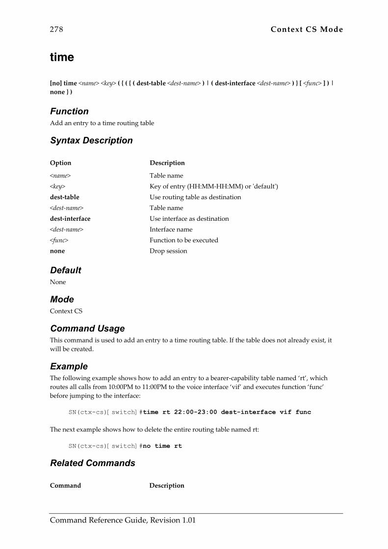
278 Context CS Mode
Command Reference Guide, Revision 1.01
time [no] time <name> <key> ( { ( { ( dest-table <dest-name> ) | ( dest-interface <dest-name> ) } [ <func> ] ) | none } )
Function Add an entry to a time routing table
Syntax Description Option Description
<name> <key> dest-table <dest-name> dest-interface <dest-name> <func> none
Table name Key of entry (HH:MM-HH:MM) or 'default') Use routing table as destination Table name Use interface as destination Interface name Function to be executed Drop session
Default None
Mode Context CS
Command Usage This command is used to add an entry to a time routing table. If the table does not already exist, it will be created.
Example The following example shows how to add an entry to a bearer-capability table named ‘rt’, which routes all calls from 10:00PM to 11:00PM to the voice interface ‘vif’ and executes function ‘func’ before jumping to the interface:
SN(ctx-cs)[switch]#time rt 22:00-23:00 dest-interface vif func The next example shows how to delete the entire routing table named rt:
SN(ctx-cs)[switch]#no time rt
Related Commands Command Description

Context CS Mode 279
Command Reference Guide, Revision 1.01
bearer-capability Creates/adds bearer-capability number routing tables/entries.
calling-party Creates/adds calling-party routing tables/entries.
called-party Creates/adds called-party number routing tables/entries.
date Creates/adds date routing tables/entries.
weekday Creates/adds day-of-week routing tables/entries.
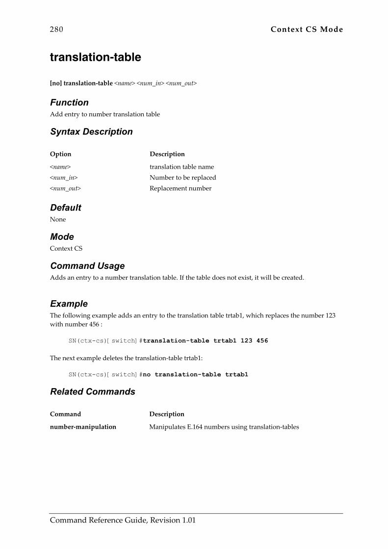
280 Context CS Mode
Command Reference Guide, Revision 1.01
translation-table [no] translation-table <name> <num_in> <num_out>
Function Add entry to number translation table
Syntax Description Option Description
<name> <num_in> <num_out>
translation table name Number to be replaced Replacement number
Default None
Mode Context CS
Command Usage Adds an entry to a number translation table. If the table does not exist, it will be created.
Example The following example adds an entry to the translation table trtab1, which replaces the number 123 with number 456 :
SN(ctx-cs)[switch]#translation-table trtab1 123 456 The next example deletes the translation-table trtab1:
SN(ctx-cs)[switch]#no translation-table trtab1
Related Commands Command Description
number-manipulation Manipulates E.164 numbers using translation-tables

Context CS Mode 281
Command Reference Guide, Revision 1.01
use tone-set-profile [no] use tone-set-profile <name>
Function Link to a tone profile
Syntax Description Option Description
<name> Name of the tone-set
Default The context cs is linked to the tone-set-profile ‘default’.
Mode Context CS
Command Usage Defines the default tone-set profile that is used for tone playback. This setting can be overridden by the settings in the interface PSTN, H.323 or ISoIP modes.
Example The following example makes the tone-set profile named toneSetD being used as default for tone playback, if no other configuration overrides it.
SN(ctx-cs)[switch]#use tone-set-profile toneSetD
Related Commands Command Description
profile tone-set Enter profile tone set configuration mode
show profile tone-set Display ton set information

282 Context CS Mode
Command Reference Guide, Revision 1.01
weekday [no] weekday <name> { sun | mon | tue | wed | thu | fri | sat | default } ( { ( { ( dest-table <dest-name> ) | ( dest-interface <dest-name> ) } [ <func> ] ) | none } )
Function Add an entry to a weekday routing table
Syntax Description Option Description
<name> sun mon tue wed thu fri sat default dest-table <dest-name> dest-interface <dest-name> <func> none
Table name Sunday Monday Tuesday Wednesday Thursday Friday Saturday Wildcard Use routing table as destination Table name Use interface as destination Interface name Function to be executed Drop session
Default None
Mode Context CS
Command Usage This command is used to add an entry to a weekday routing table. If the table does not already exist, it will be created.
Example The following example shows how to add an entry to a weekday table named ‘rt’, which routes all calls on mondays to the voice interface ‘vif’ and executes function ‘func’ before jumping to the interface:
SN(ctx-cs)[switch]#weekday rt mon dest-interface vif func
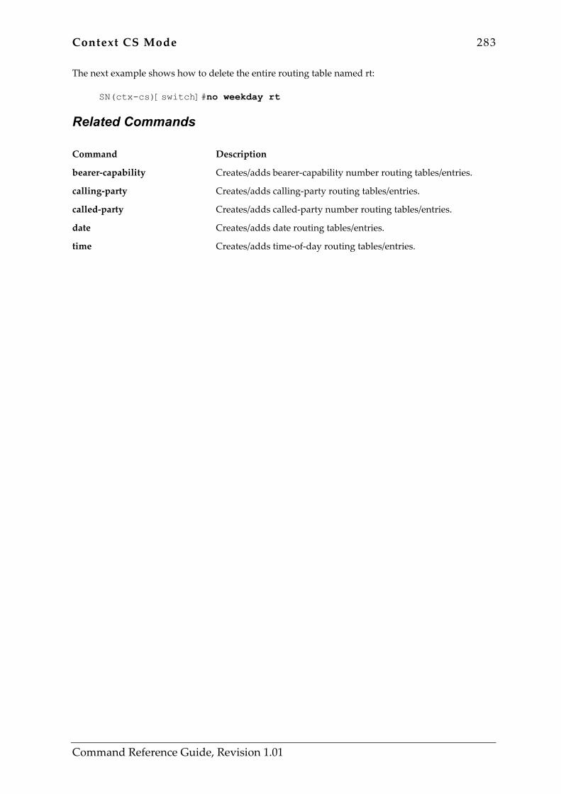
Context CS Mode 283
Command Reference Guide, Revision 1.01
The next example shows how to delete the entire routing table named rt:
SN(ctx-cs)[switch]#no weekday rt
Related Commands Command Description
bearer-capability Creates/adds bearer-capability number routing tables/entries.
calling-party Creates/adds calling-party routing tables/entries.
called-party Creates/adds called-party number routing tables/entries.
date Creates/adds date routing tables/entries.
time Creates/adds time-of-day routing tables/entries.
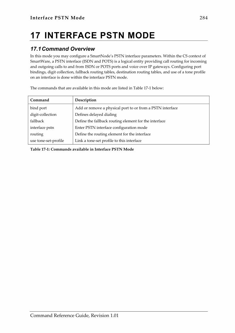
Interface PSTN Mode 284
Command Reference Guide, Revision 1.01
17 INTERFACE PSTN MODE 17.1 Command Overview In this mode you may configure a SmartNode’s PSTN interface parameters. Within the CS context of SmartWare, a PSTN interface (ISDN and POTS) is a logical entity providing call routing for incoming and outgoing calls to and from ISDN or POTS ports and voice over IP gateways. Configuring port bindings, digit collection, fallback routing tables, destination routing tables, and use of a tone profile on an interface is done within the interface PSTN mode. The commands that are available in this mode are listed in Table 17-1 below:
Command Description
bind port digit-collection fallback interface pstn routing use tone-set-profile
Add or remove a physical port to or from a PSTN interface Defines delayed dialing Define the fallback routing element for the interface Enter PSTN interface configuration mode Define the routing element for the interface Link a tone-set profile to this interface
Table 17-1: Commands available in Interface PSTN Mode
Interface PSTN Mode 285
Command Reference Guide, Revision 1.01
bind port [no] bind port <slot> <port>
Function Add or remove a physical port to or from a PSTN interface
Syntax Description Option Description
port <slot> <port>
Add or remove a physical port to/from a PSTN interface Slot number Port number
Default None
Mode Interface PSTN
Command Usage The command is used to bind one or more physical PSTN ports to a logical PSTN session-router interface. The command can be used multiple times in the same PSTN interface to add multiple PSTN ports.
Example The following example binds PSTN port 0 0 and 0 1 to the PSTN interface <name>:
SN(ctx-cs)[switch]#interface pstn <name> SN(if-pstn)[<name>]#bind port 0 0 SN(if-pstn)[<name>]#bind port 0 1
The next example removes all bound ports from the PSTN interface <name>:
SN(if-pstn)[<name>]#no bind port
Related Commands None
286 Interface PSTN Mode
Command Reference Guide, Revision 1.01
digit-collection [no] digit-collection { ( timeout [ <val> ] ) | ( terminating-char <val> ) | ( nr-length <val> ) }
Function Defines delayed dialing
Syntax Description Option Description
timeout <val> terminating-char <val> nr-length <val>
Dialing after a timeout Timeout in seconds Defines the dial termination character Termination character Defines the minimum called-party number length Minimum required number of digits
Default None
Mode Interface PSTN
Command Usage The command causes initiation of calls originated from this voice interface to be deferred until the condition indicated in this command is met. There are three different conditions, which can be specified. These conditions all be used separately, or they can also be combined. This feature is used whenever a gatekeeper or PBX requires a minimum number of called-party number digits or even the complete called-party number in the setup message. This is usually the case for systems, which do not support overlapped-dialing. The first condition is a timeout, which indicates how long the call initiation shall be deferred after the last called party number digit has been received. The second condition is a termination-character, which indicates that the number is now complete and the setup message can be sent. Usually the ‘#’ character is used for this purpose, however any other E.164 character can be used. If the timeout condition is also used, the reception of the terminating-character will cause the setup to be sent, before the timeout expired. The third condition is a minimal required number length. The setup message will under no circumstances be sent if not at lest the indicated minimum number of called-party number digits are ready to be sent. If also a timeout is specified, this timeout will only be started, after the minimum number of called-party number digits are ready. Also, if a terminating-character is defined, it will not cause a number to be sent, which is shorter than the configured minimal number-length. It can only be used to stop a pending timeout, and send the setup immediately instead.

Interface PSTN Mode 287
Command Reference Guide, Revision 1.01
Example The following example waits for at least 3 digits befor forwarding the call-setup message to the physical interface:
SN(if-pstn)[<name>]#digit-collection nr-length 3 The next example waits 3 seconds after the last called-party number digit has been received, or until the ‘#’ character has been received, before sending the call-setup message:
SN(if-pstn)[<name>]#digit-collection timeout 3 SN(if-pstn)[<name>]#digit-collection terminating-char #
Related Commands None
288 Interface PSTN Mode
Command Reference Guide, Revision 1.01
fallback [no] fallback { ( dest-table <name> ) | ( dest-interface <name> ) }
Function Define the fallback routing element for the interface
Syntax Description Option Description
dest-table <name> dest-interface <name>
Use routing table as destination Table name Use interface as destination Interface name
Default None
Mode Interface PSTN
Command Usage Defines the fallback (secondary) destination to be used for calls incoming over this voice interface. The fallback destination will be used, if the call-setup over the primary destination indicated in the ‘routing’ command failed. You may either indicate a routing-table or a voice-interface, to which the call shall be routed to.
Example The following example defines the voice interface ‘voif’ to be used as fallback destination:
SN(if-pstn)[<name>]#fallback dest-interface voif The next example defines the routing table ‘rtab’ to be used as fallback destination:
SN(if-pstn)[<name>]#fallback dest-table rtab
Related Commands Command Description
routing Defines the primary routing destination for calls incoming over this voice interface.
Interface PSTN Mode 289
Command Reference Guide, Revision 1.01
interface pstn [no] interface pstn <if-name>
Function Enter PSTN interface configuration mode
Syntax Description Option Description
pstn <if-name>
Enter pstn interface configuration mode Interface name
Default None
Mode Interface PSTN
Command Usage Enters PSTN voice interface configuration mode. If the interface does not already exist, it will be created. The inverted form of the command will delete the PSTN voice interface.
Example The following examples creates a PSTN interface named <name>:
SN(cfg)#context cs SN(ctx-cs)[switch]#interface pstn <name>
The next example deletes the PSTN interface named <name>:
SN(ctx-cs)[switch]#no interface pstn <name>
Related Commands Command Description
interface h323 Creates a H.323 voice interface
interface isoip Creates an IsoIP voice interface

290 Interface PSTN Mode
Command Reference Guide, Revision 1.01
routing [no] routing { ( dest-table <name> ) | ( dest-interface <name> ) }
Function Define the routing element for the interface
Syntax Description Option Description
dest-table <name> dest-interface <name>
Use routing table as destination Table name Use interface as destination Interface name
Default None
Mode Interface PSTN
Command Usage The command is used to define the primary routing destination for the voice interface. The destination can either directly be another voice interface, or a routing table. All calls incoming on a voice interface will first be forwarded to the destination indicated in the ‘routing’ command. If the call-setup to this destination fails, the destination indicated in the ‘fallback’ command will be used.
Example The following examples uses the voice interface ‘vif’ as the destination for all inbound calls:
SN(if-pstn)[<name>]#routing dest-interface vif The next example uses the routing table ‘rtab’ as the destination for all inbound calls:
SN(if-pstn)[<name>]#routing dest-table rtab
Related Commands Command Description
fallback Defines the fallback (secondary) destination for all inbound calls on this interface.
Interface PSTN Mode 291
Command Reference Guide, Revision 1.01
use tone-set-profile [no] use tone-set-profile <name>
Function Link a tone-set profile to this interface
Syntax Description Option Description
<name> Name of the tone-set
Default No linkage is defined. The tone-set linked to context CS is used as default.
Mode Interface PSTN
Command Usage A certain voice interface may be required to play tones that look different that the tones on other interfaces. This command defines that an own tone-set shall be used for all calls going through this interface. The setting here overrides the tone-set profile linked to the context CS.
Example The following example defines that a special tone-set named ‘specialSetD’ shall be used on this interface:
SN(if-pstn)[<name>]#use tone-set-profile specialSetD The next example unlinks any tone-set from the interface. The tone-set configured in context CS will be used further on.
SN(if-pstn)[<name>]#no use tone-set-profile
Related Commands Command Description
use tone-set profile Link a tone-set profile to an interface
show profile tone-set Display ton set information
profile tone-set Enter profile tone set configuration mode

Interface H.323 Mode 292
Command Reference Guide, Revision 1.01
18 INTERFACE H.323 MODE 18.1 Command Overview In this mode you may configure a SmartNode’s H.323 interface parameters. Defining the H.323 gateway to which an H.323 interface gets bound, the audio codec that is used, the dejitter behavior and other settings for an H.323 interface is done using the interface H.323 mode. The commands that are available in this mode are listed in Table 18-1 below:
Command Description
bind gateway codec dejitter-grow-attenuation dejitter-grow-step dejitter-max-delay dejitter-max-packet-loss dejitter-mode dejitter-shrink-speed digit-collection dtmf-relay echo-canceller fallback interface h323 portaddress remoteip routing silence-compression use tone-set-profile voice-volume
Bind selected interface to a H.323 gateway Define the audio codec to be used on selected interface Set the dejitter grow attenuation parameter Set the dejitter grow step parameter Set the dejitter maximal delay Set the dejitter maximal packet loss Set the dejitter mode used on selected interface Set the dejitter shrink speed parameter Define delayed dialing Set the DTMF relay flag Enable or disable the echo canceller Define the fallback routing element for the interface Enter H.323 interface configuration mode Define or delete port address used for H.323 calls Set or delete remote call signaling IP address Define the routing element for the interface Enable or disable silence compression Link a tone-set profile to the selected interface Set the voice volume
Table 18-1: Commands available in Interface H.323 Mode
Interface H.323 Mode 293
Command Reference Guide, Revision 1.01
bind gateway [no] bind gateway <name>
Function Bind selected interface to a H.323 gateway
Syntax Description Option Description
<name> Name of the H.323 gateway
Default By default the H.323 gateway named h323 is bound.
Mode Interface H.323
Command Usage This command is used to bind the H.323 voice interface to a specific H.323 gateway. There is currently only one H.323 gateway per system. Since all H.323 voice interfaces are bound per default to this gateway, there is currently no need to use this commend.
Example The following example shows how to bind the interface to the H.323 gateway:
SN(if-h323)[<if-name>]#bind gateway h323
Related Commands None
294 Interface H.323 Mode
Command Reference Guide, Revision 1.01
codec [no] codec { g711alaw64k | g711ulaw64k | g723_6k3 | g729 | transparent } [ exclusive ]
Function Define the audio codec to be used on selected interface
Syntax Description Option Description
g711alaw64k g711ulaw64k g723_6k3 g729 transparent exclusive
G.711 A-Law 64 kbps G.711 u-Law 64 kbps G.723.1 6.3 kbps G.729a 8 kbps Transparent ISDN data no echo cancellation Only the indicated codec is allowed
Default If you do not specify a codec for the selected H.323 interface, the default codec specified in the H.323 gateway will be used.
Mode Interface H.323
Command Usage Defines the preferred codec for outbound calls over the voice interface. This command has only an effect, if the fastconnect procedure is used. The codec indicated in this command must also be present in the list of supported codecs of the H.323 gateway. If the exclusive option is specified, only the indicated codec will be allowed. If this codec is not supported by the remote system, the call will fail. The session-router will only select the voice interface, if the codec of the voice interface matches the codec of the inbound call, or if the codec of the inbound call cannot be determined at the time the routing decision has to be made.
Example The following examples uses G.711 A-Law as the preferred codec
SN(if-h323)[<if-name>]#codec g711alaw64k The next example forces G.729 to be used:
SN(if-h323)[<if-name>]#codec g729 exclusive
Related Commands None
Interface H.323 Mode 295
Command Reference Guide, Revision 1.01
dejitter-grow-attenuation dejitter-grow-attenuation <dejitter_grow_attenuation>
Function Set the dejitter grow attenuation parameter
Syntax Description Option Description
<dejitter_grow_attenuation> Dejitter grow attenuation
Default No dejitter-grow-attenuation is defined in the interface. The value is taken from the voip-profile linked to the H.323 gateway.
Mode Interface H.323
Command Usage Overrides the setting in the voip-profile linked to H.323 gateway for all calls going through this interface. See the dejitter-grow-attenuation command description in the ‘profile voip’ mode for details.
Example The following example overrides the setting in the voip-profile linked to the H.323 gateway.
SN(if-h323)[<if-name>]#dejitter-grow-attenuation 3
Related Commands Command Description
dejitter-grow-attenuation Set dejitter grow attenuation parameter
use profile voip Link gateway to a VoIP profile

296 Interface H.323 Mode
Command Reference Guide, Revision 1.01
dejitter-grow-step dejitter-grow-step <dejitter_grow_step>
Function Set the dejitter grow step parameter
Syntax Description Option Description
<dejitter_grow_step> Dejitter grow step
Default No dejitter-grow-step is defined in the interface. The value is taken from the voip-profile linked to the H.323 gateway.
Mode Interface H.323
Command Usage Overrides the setting in the voip-profile linked to H.323 gateway for all calls going through this interface. See the dejitter-grow-step command description in the ‘profile voip’ mode for details.
Example The following example overrides the setting in the voip-profile linked to the H.323 gateway.
SN(if-h323)[<if-name>]#dejitter-grow-step 2
Related Commands Command Description
dejitter-grow-step Set dejitter grow step parameter
use profile voip Link gateway to a VoIP profile
Interface H.323 Mode 297
Command Reference Guide, Revision 1.01
dejitter-max-delay dejitter-max-delay <dejitter_max_delay>
Function Set the dejitter maximal delay
Syntax Description Option Description
<dejitter_max_delay> Dejitter max delay
Default No dejitter-max-delay is defined in the interface. The value is taken from the voip-profile linked to the H.323 gateway.
Mode Interface H.323
Command Usage Overrides the setting in the voip-profile linked to H.323 gateway for all calls going through this interface. See the dejitter-max-delay command description in the ‘profile voip’ mode for details.
Example The following example overrides the setting in the voip-profile linked to the H.323 gateway.
SN(if-h323)[<if-name>]#dejitter-max-delay 150
Related Commands Command Description
dejitter-max-delay Set dejitter maximal delay
use profile voip Link gateway to a VoIP profile
298 Interface H.323 Mode
Command Reference Guide, Revision 1.01
dejitter-max-packet-loss dejitter-max-packet-loss <dejitter_max_packet_loss>
Function Set the dejitter maximal packet loss
Syntax Description Option Description
<dejitter_max_packet_loss> Dejitter max delay
Default No dejitter-max-packet-loss is defined in the interface. The value is taken from the voip-profile linked to the H.323 gateway.
Mode Interface H.323
Command Usage Overrides the setting in the voip-profile linked to H.323 gateway for all calls going through this interface. See the dejitter-max-packet-loss command description in the ‘profile voip’ mode for details.
Example The following example overrides the setting in the voip-profile linked to the H.323 gateway.
SN(if-h323)[<if-name>]#dejitter-max-packet-loss 3
Related Commands Command Description
dejitter-max-packet-loss Set dejitter maximal packet loss
use profile voip Link gateway to a VoIP profile
Interface H.323 Mode 299
Command Reference Guide, Revision 1.01
dejitter-mode dejitter-mode { adaptive | static}
Function Set the dejitter mode used on selected interface
Syntax Description Option Description
adaptive static
Selects adaptive dejitter mode Selects static dejitter mode
Default No dejitter-mode is defined in the interface. The value is taken from the VoIP profile linked to the H.323 gateway.
Mode Interface H.323
Command Usage Overrides the setting in the voip-profile linked to H.323 gateway for all calls going through this interface. See the dejitter-mode command description in the ‘profile voip’ mode for details.
Example The following example overrides the setting in the voip-profile linked to the H.323 gateway.
SN(if-h323)[<if-name>]#dejitter-mode static
Related Commands Command Description
dejitter-mode Set dejitter buffer operation mode
use profile voip Link gateway to a VoIP profile
300 Interface H.323 Mode
Command Reference Guide, Revision 1.01
dejitter-shrink-speed dejitter-shrink-speed <dejitter_shrink_speed>
Function Set the dejitter shrink speed parameter
Syntax Description Option Description
<dejitter_shrink_speed> Dejitter shrink speed
Default No dejitter-shrink-speed is defined in the interface. The value is taken from the voip-profile linked to the H.323 gateway.
Mode Interface H.323
Command Usage Overrides the setting in the voip-profile linked to H.323 gateway for all calls going through this interface. See the dejitter-shrink-speed command description in the ‘profile voip’ mode for details.
Example The following example overrides the setting in the voip-profile linked to the H.323 gateway.
SN(if-h323)[<if-name>]#dejitter-shrink-speed 3
Related Commands Command Description
dejitter-shrink-speed Set dejitter shrink speed parameter
use profile voip Link gateway to a VoIP profile
Interface H.323 Mode 301
Command Reference Guide, Revision 1.01
digit-collection [no] digit-collection { ( timeout [ <val> ] ) | ( terminating-char <val> ) | ( nr-length <val> ) }
Function Define delayed dialing
Syntax Description Option Description
timeout <val> terminating-char <val> nr-length <val>
Dialing after a timeout Timeout in seconds Defines the dial termination character Termination character Defines the minimum called-party number length Minimum required number of digits
Default None
Mode Interface H.323
Command Usage The command causes initiation of calls originated from this voice interface to be deferred until the condition indicated in this command is met. There are three different conditions, which can be specified. These conditions all be used separately, or they can also be combined. This feature is used whenever a gatekeeper or PBX requires a minimum number of called-party number digits or even the complete called-party number in the setup message. This is usually the case for systems, which do not support overlapped-dialing. The first condition is a timeout, which indicates how long the call initiation shall be deferred after the last called party number digit has been received. The second condition is a termination-character, which indicates that the number is now complete and the setup message can be sent. Usually the ‘#’ character is used for this purpose, however any other E.164 character can be used. If the timeout condition is also used, the reception of the terminating-character will cause the setup to be sent, before the timeout expired. The third condition is a minimal required number length. The setup message will under no circumstances be sent if not at lest the indicated minimum number of called-party number digits are ready to be sent. If also a timeout is specified, this timeout will only be started, after the minimum number of called-party number digits are ready. Also, if a terminating-character is defined, it will not cause a number to be sent, which is shorter than the configured minimal number-length. It can only be used to stop a pending timeout, and send the setup immediately instead.

302 Interface H.323 Mode
Command Reference Guide, Revision 1.01
Example The following example waits for at least 3 digits befor forwarding the call-setup message to the physical interface:
SN(if-h323)[<if-name>]#digit-collection nr-length 3 The next example waits 3 seconds after the last called-party number digit has been received, or until the ‘#’ character has been received, before sending the call-setup message:
SN(if-h323)[<if-name>]#digit-collection timeout 3 SN(if-h323)[<if-name>]#digit-collection terminating-char #
Related Commands None
Interface H.323 Mode 303
Command Reference Guide, Revision 1.01
dtmf-relay [no] dtmf-relay
Function Set the DTMF relay flag
Syntax Description Option Description
This command has no keywords or options
Default No dtmf-relay setting is defined in the interface. The value is taken from the voip-profile linked to the H.323 gateway.
Mode Interface H.323
Command Usage Overrides the setting in the voip-profile linked to H.323 gateway for all calls going through this interface. See the dtmf-relay command description in the ‘profile voip’ mode for details.
Example The following example overrides the setting in the voip-profile linked to the H.323 gateway.
SN(if-h323)[<if-name>]#no dtmf-relay
Related Commands Command Description
dtmf-relay Enables or disables DTMF relay in profile VoIP mode
use voip-profile Link gateway to a VoIP profile

304 Interface H.323 Mode
Command Reference Guide, Revision 1.01
echo-canceller [no] echo-canceller
Function Enable or disable the echo canceller
Syntax Description Option Description
This command has no keywords or options
Default No echo canceller setting is defined in the interface. The value is taken from the voip-profile linked to the H.323 gateway.
Mode Interface H.323
Command Usage Overrides the setting in the voip-profile linked to H.323 gateway for all calls going through this interface. See the echo-canceller command description in the ‘profile voip’ mode for details.
Example The following example overrides the setting in the voip-profile linked to the H.323 gateway.
SN(if-h323)[<if-name>]#no echo-canceller
Related Commands Command Description
echo-canceller Enables or disables the echo canceller in profile VoIP mode
use profile voip Link gateway to a VoIP profile

Interface H.323 Mode 305
Command Reference Guide, Revision 1.01
fallback [no] fallback { ( dest-table <name> ) | ( dest-interface <name> ) }
Function Define the fallback routing element for the interface
Syntax Description Option Description
dest-table <name> dest-interface <name>
Use routing table as destination Table name Use interface as destination Interface name
Default None
Mode Interface H.323
Command Usage Defines the fallback (secondary) destination to be used for calls incoming over this voice interface. The fallback destination will be used, if the call-setup over the primary destination indicated in the ‘routing’ command failed. You may either indicate a routing-table or a voice-interface, to which the call shall be routed to.
Example The following example defines the voice interface ‘voif’ to be used as fallback destination:
SN(if-h323)[<if-name>]#fallback dest-interface voif The next example defines the routing table ‘rtab’ to be used as fallback destination:
SN(if-h323)[<if-name>]#fallback dest-table rtab
Related Commands Command Description
routing Defines the primary routing destination for calls incoming over this voice interface.
306 Interface H.323 Mode
Command Reference Guide, Revision 1.01
interface h323 [no] interface h323 <if-name>
Function Enter H.323 interface configuration mode
Syntax Description Option Description
<if-name> Enter H.323 interface configuration mode Interface name
Default None
Mode Interface H.323
Command Usage Enters H.323 voice interface configuration mode. If the interface does not already exist, it will be created. The inverted form of the command will delete the H.323 voice interface.
Example The following examples creates a H.323 interface named <if-name>:
SN(ctx-cs)[switch]#interface h323 <if-name> SN(if-h323)[if-name]#
The next example deletes the H.323 interface named <if-name>:
SN(ctx-cs)[switch]#no interface h323 <if-name>
Related Commands Command Description
interface pstn Creates a PSTN voice interface
interface isoip Creates an ISoIP voice interface
Interface H.323 Mode 307
Command Reference Guide, Revision 1.01
portaddress [no] portaddress <portaddress>
Function Define or delete port address used for H.323 calls
Syntax Description Option Description
<portaddress> Port address (decimal)
Default None
Mode Interface H.323
Command Usage Defines the portaddress to be used with the call. For outbound calls, this information is sent to the H.323 gateway. The gateway may (depending on the tunnelling protocol used) send the information to the remote peer, which can use the information to identify the physical destination PSTN port to be used for the call or signalling message. The H.323 gateway can use this information. For inbound calls, the session-router will look for a H.323 voice interface, which contains the portaddress of the incoming call. If found that interface will be used. If no interface with match portaddress is found, the call will be rejected. To use portaddresses, you need to enable ‘q931-tunneling’ in the H.323 gateway configuration mode. Warning: Several ISDN supplementary services will not work, if this option is not configured.
Example The following example sets the portaddress to 4:
SN(if-h323)[<if-name>]#portaddress 4 The next example removes the portaddress from the voice interface:
SN(if-h323)[<if-name>]#no portaddress
Related Commands Command Description
q931-tunneling Enables Q.931 message tunneling and portaddress support in the H.323 gateway.
308 Interface H.323 Mode
Command Reference Guide, Revision 1.01
remoteip [no] remoteip <remote_ip>
Function Set or delete remote call signaling IP address
Syntax Description Option Description
<remote_ip> IP address
Default None
Mode Interface H.323
Command Usage Defines the IP destination call-signalling address for outbound calls on this interface. The session-router will select this interface for inbound calls, if the call-signalling IP address of the remote peer matches the IP address specified with this command. The remote IP address shall only be specified, if no gatekeeper is used. Otherwise, the gatekeeper will provide the remote IP address. Warning: Do not use this command if a gatekeeper is used, as it might interfere with RAS signalling.
Example The following examples sets the remote call-signalling IP address to 172.16.3.2:
SN(if-h323)[<if-name>]#remoteip 172.16.3.2 The next example removes the remote call-signalling IP address from the voice interface:
SN(if-h323)[<if-name>]#no remoteip
Related Commands None
Interface H.323 Mode 309
Command Reference Guide, Revision 1.01
routing [no] routing { ( dest-table <name> ) | ( dest-interface <name> ) }
Function Define the routing element for the interface
Syntax Description Option Description
dest-table <name> dest-interface <name>
Use routing table as destination Table name Use interface as destination Interface name
Default None
Mode Interface H.323
Command Usage The command is used to define the primary routing destination for the voice interface. The destination can either directly be another voice interface, or a routing table. All calls incoming on a voice interface will first be forwarded to the destination indicated in the ‘routing’ command. If the call-setup to this destination fails, the destination indicated in the ‘fallback’ command will be used.
Example The following examples uses the voice interface ‘vif’ as the destination for all inbound calls:
SN(if-h323)[<if-name>]#routing dest-interface vif The next example uses the routing table ‘rtab’ as the destination for all inbound calls:
SN(if-h323)[<if-name>]#routing dest-table rtab
Related Commands Command Description
fallback Defines the fallback (secondary) destination for all inbound calls on this interface.
310 Interface H.323 Mode
Command Reference Guide, Revision 1.01
silence-compression [no] silence-compression
Function Enable or disable silence compression
Syntax Description Option Description
This command has no keywords or options
Default No silence compression setting is defined in the interface. The value is taken from the voip-profile linked to the H.323 gateway.
Mode Interface H.323
Command Usage Overrides the setting in the voip-profile linked to H.323 gateway for all calls going through this interface. See the silence-compression command description in the ‘profile voip’ mode for details.
Example The following example overrides the setting in the voip-profile linked to the H.323 gateway.
SN(if-h323)[<if-name>]#no silence-compression
Related Commands Command Description
silence-compression Enable or disable silence compression or comfort noise generation in profile VoIP mode
use profile voip Link gateway to a VoIP profile
Interface H.323 Mode 311
Command Reference Guide, Revision 1.01
use tone-set-profile [no] use tone-set-profile <name>
Function Link a tone-set profile to the selected interface
Syntax Description Option Description
<name> Name of the tone-set
Default No linkage is defined. The tone-set linked to context CS is used as default.
Mode Interface H.323
Command Usage A certain voice interface may be required to play tones that look different that the tones on other interfaces. This command defines that an own tone-set shall be used for all calls going through this interface. The setting here overrides the tone-set profile linked to the context CS.
Example The following example defines that a special tone-set named tonsetDE shall be used on this interface:
SN(if-h323)[<if-name>]#use tone-set-profile tonsetDE The next example unlinks any tone-set from the interface. The tone-set configured in context CS will be used further on.
SN(if-h323)[<if-name>]#no use tone-set-profile
Related Commands Command Description
use tone-set profile Link to a tone profile
show profile tone-set Display tone set information
profile tone-set Enter tone set profile configuration mode

312 Interface H.323 Mode
Command Reference Guide, Revision 1.01
voice-volume voice-volume <voice_volume>
Function Set the voice volume
Syntax Description Option Description
<voice_volume> Voice volume
Default No voice volume setting is defined in the interface. The value is taken from the voip-profile linked to the H.323 gateway.
Mode Interface H.323
Command Usage Overrides the setting in the voip-profile linked to H.323 gateway for all calls going through this interface. See the voice-volume command description in the ‘profile voip’ mode for details.
Example The following example overrides the setting in the voip-profile linked to the H.323 gateway.
SN(if-h323)[<if-name>]#voice-volume -10
Related Commands Command Description
voice-volume Set the voice volume in interface ISoIP mode
use profile voip Link gateway to a VoIP profile
Interface ISoIP Mode 313
Command Reference Guide, Revision 1.01
19 INTERFACE ISOIP MODE 19.1 Command Overview In this mode you may configure a SmartNode’s ISoIP interface parameters. Defining the ISoIP gateway to which an ISoIP interface gets bound, the audio codec that is used, the dejitter behavior and other settings for an ISoIP interface is done using the interface ISoIP mode. The commands that are available in this mode are listed in Table 19-1 below:
Command Description
bind gateway isoip codec dejitter-grow-attenuation dejitter-grow-step dejitter-max-delay dejitter-max-packet-loss dejitter-mode dejitter-shrink-speed digit-collection dtmf-relay echo-canceller fallback interface isoip portaddress remoteip routing silence-compression use tone-set-profile voice-volume
Bind the selected interface to an ISoIP gateway Define audio codec to be used on selected interface Set the dejitter grow attenuation parameter Set the dejitter grow step parameter Set the dejitter maximum delay Set the dejitter maximum packet loss Set the dejitter mode Set the dejitter shrink speed parameter Defines delayed dialing Set the DTMF relay flag Enable or disable the echo canceller Define the fallback routing element for the selected interface Enter ISoIP interface configuration mode Set or clear port address Set or clear remote call signaling IP address Define the routing element for the selected interface Enable or disable silence compression on selected interface Link tone-set profile to the selected interface Set the voice volume
Table 19-1: Commands available in Interface ISoIP Mode
314 Interface ISoIP Mode
Command Reference Guide, Revision 1.01
bind gateway isoip [no] bind gateway isoip
Function Bind the selected interface to an ISoIP gateway
Syntax Description Option Description
This command has no keywords or options
Default None
Mode Interface ISoIP
Command Usage This command is used to bind the ISoIP voice interface to a specific ISoIP gateway. There is currently only one ISoIP gateway per system. Since all ISoIP voice interfaces are bound per default to this gateway, there is currently no need to use this commend.
Example The following example shows how to bind the interface <if-name> to the ISoIP gateway:
SN(if-isoip)[<if-name>]#bind gateway isoip
Related Commands None
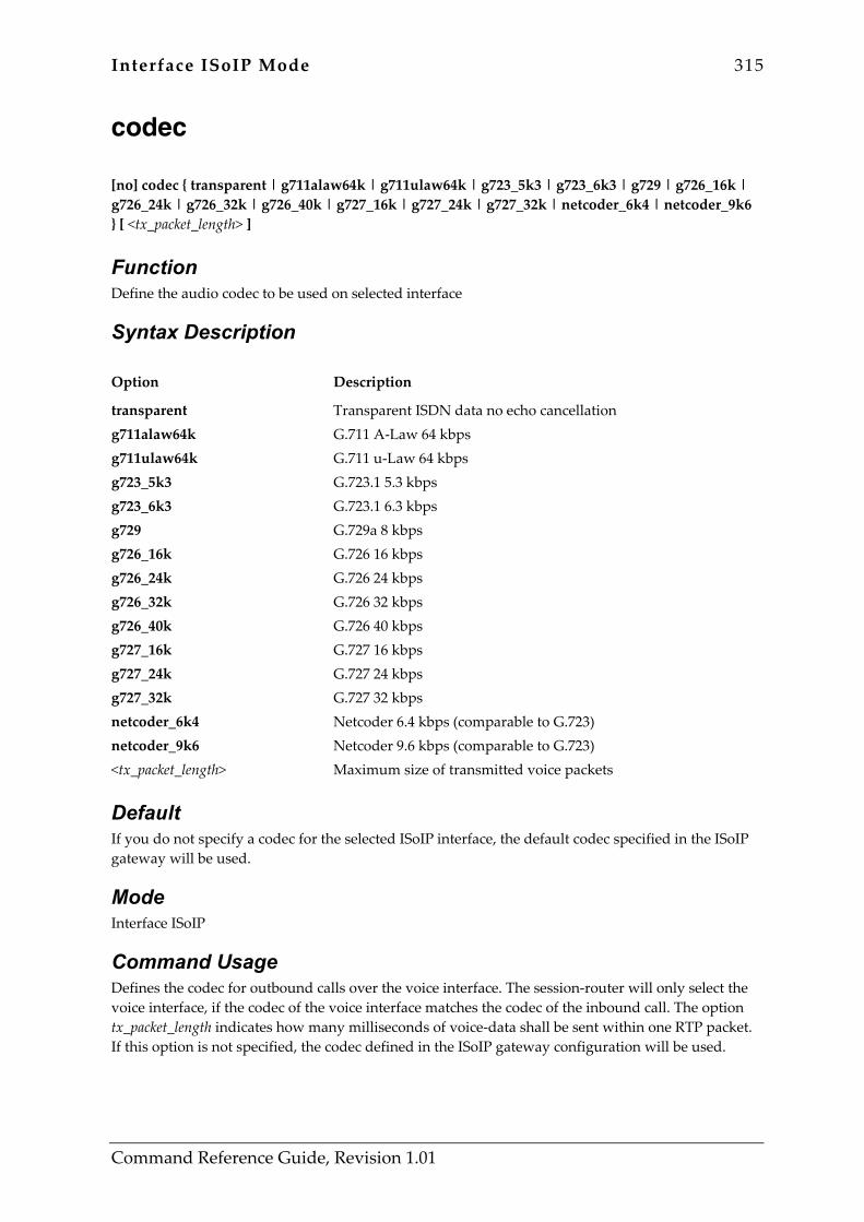
Interface ISoIP Mode 315
Command Reference Guide, Revision 1.01
codec [no] codec { transparent | g711alaw64k | g711ulaw64k | g723_5k3 | g723_6k3 | g729 | g726_16k | g726_24k | g726_32k | g726_40k | g727_16k | g727_24k | g727_32k | netcoder_6k4 | netcoder_9k6 } [ <tx_packet_length> ]
Function Define the audio codec to be used on selected interface
Syntax Description Option Description
transparent g711alaw64k g711ulaw64k g723_5k3 g723_6k3 g729 g726_16k g726_24k g726_32k g726_40k g727_16k g727_24k g727_32k netcoder_6k4 netcoder_9k6 <tx_packet_length>
Transparent ISDN data no echo cancellation G.711 A-Law 64 kbps G.711 u-Law 64 kbps G.723.1 5.3 kbps G.723.1 6.3 kbps G.729a 8 kbps G.726 16 kbps G.726 24 kbps G.726 32 kbps G.726 40 kbps G.727 16 kbps G.727 24 kbps G.727 32 kbps Netcoder 6.4 kbps (comparable to G.723) Netcoder 9.6 kbps (comparable to G.723) Maximum size of transmitted voice packets
Default If you do not specify a codec for the selected ISoIP interface, the default codec specified in the ISoIP gateway will be used.
Mode Interface ISoIP
Command Usage Defines the codec for outbound calls over the voice interface. The session-router will only select the voice interface, if the codec of the voice interface matches the codec of the inbound call. The option tx_packet_length indicates how many milliseconds of voice-data shall be sent within one RTP packet. If this option is not specified, the codec defined in the ISoIP gateway configuration will be used.

316 Interface ISoIP Mode
Command Reference Guide, Revision 1.01
Example The following example uses G.723 at 6.3 kbps with a packetization time of 60 milliseconds:
SN(if-isoip)[<if-name>]#codec g723_6k3 60 The next example removes the codec option from the voice interface:
SN(if-isoip)[<if-name>]#no codec
Related Commands None
Interface ISoIP Mode 317
Command Reference Guide, Revision 1.01
dejitter-grow-attenuation dejitter-grow-attenuation <dejitter_grow_attenuation>
Function Set the dejitter grow attenuation parameter
Syntax Description Option Description
<dejitter_grow_attenuation> Dejitter grow attenuation
Default No dejitter-grow-attenuation is defined in the interface. The value is taken from the voip-profile linked to the ISoIP gateway.
Mode Interface ISoIP
Command Usage Overrides the setting in the voip-profile linked to ISoIP gateway for all calls going through this interface. See the dejitter-grow-attenuation command description in the Profile VoIP Mode for details.
Example The following example overrides the setting in the voip-profile linked to the ISoIP gateway.
SN(if-isoip)[<if-name>]#dejitter-grow-attenuation 3
Related Commands Command Description
dejitter-grow-attenuation Set dejitter grow attenuation parameter
use profile voip Link gateway to a VoIP profile
318 Interface ISoIP Mode
Command Reference Guide, Revision 1.01
dejitter-grow-step dejitter-grow-step <dejitter_grow_step>
Function Set the dejitter grow step parameter
Syntax Description Option Description
<dejitter_grow_step> Dejitter grow step
Default No dejitter-grow-step is defined in the interface. The value is taken from the voip-profile linked to the ISoIP gateway.
Mode Interface ISoIP
Command Usage Overrides the setting in the voip-profile linked to ISoIP gateway for all calls going through this interface. See the dejitter-grow-step command description in the ‘profile voip’ mode for details.
Example The following example overrides the setting in the voip-profile linked to the ISoIP gateway.
SN(if-isoip)[<if-name>]#dejitter-grow-step 2
Related Commands Command Description
dejitter-grow-step Set dejitter grow step parameter
use profile voip Link gateway to a VoIP profile
Interface ISoIP Mode 319
Command Reference Guide, Revision 1.01
dejitter-max-delay dejitter-max-delay <dejitter_max_delay>
Function Set the dejitter maximum delay
Syntax Description Option Description
<dejitter_max_delay> Dejitter max delay
Default No dejitter-max-delay is defined in the interface. The value is taken from the voip-profile linked to the ISoIP gateway.
Mode Interface ISoIP
Command Usage Overrides the setting in the voip-profile linked to ISoIP gateway for all calls going through this interface. See the dejitter-max-delay command description in the ‘profile voip’ mode for details.
Example The following example overrides the setting in the voip-profile linked to the ISoIP gateway.
SN(if-isoip)[<if-name>]#dejitter-max-delay 150
Related Commands Command Description
dejitter-max-delay Set dejitter maximal delay parameter
use profile voip Link gateway to a VoIP profile

320 Interface ISoIP Mode
Command Reference Guide, Revision 1.01
dejitter-max-packet-loss dejitter-max-packet-loss <dejitter_max_packet_loss>
Function Set the dejitter maximum packet loss
Syntax Description Option Description
<dejitter_max_packet_loss> Dejitter max delay
Default No dejitter-max-packet-loss is defined in the interface. The value is taken from the voip-profile linked to the ISoIP gateway.
Mode Interface ISoIP
Command Usage Overrides the setting in the voip-profile linked to ISoIP gateway for all calls going through this interface. See the dejitter-max-packet-loss command description in the ‘profile voip’ mode for details.
Example The following example overrides the setting in the voip-profile linked to the ISoIP gateway.
SN(if-isoip)[<if-name>]#dejitter-max-packet-loss 3
Related Commands Command Description
dejitter-max-packet-loss Set dejitter maximal packet loss parameter
use profile voip Link gateway to a VoIP profile
Interface ISoIP Mode 321
Command Reference Guide, Revision 1.01
dejitter-mode dejitter-mode { adaptive|static }
Function Set the dejitter mode
Syntax Description Option Description
adaptive static
Select adaptive dejitter mode Select static dejitter mode
Default No dejitter-mode is defined in the interface. The value is taken from the voip-profile linked to the ISoIP gateway.
Mode Interface ISoIP
Command Usage Overrides the setting in the voip-profile linked to ISoIP gateway for all calls going through this interface. See the dejitter-mode command description in the ‘profile voip’ mode for details.
Example The following example overrides the setting in the voip-profile linked to the ISoIP gateway.
SN(if-isoip)[<if-name>]#dejitter-mode static
Related Commands Command Description
dejitter-mode Set dejitter buffer operation mode
use profile voip Link gateway to a VoIP profile

322 Interface ISoIP Mode
Command Reference Guide, Revision 1.01
dejitter-shrink-speed dejitter-shrink-speed <dejitter_shrink_speed>
Function Set the dejitter shrink speed parameter
Syntax Description Option Description
<dejitter_shrink_speed> Dejitter shrink speed
Default No dejitter-shrink-speed is defined in the interface. The value is taken from the voip-profile linked to the ISoIP gateway.
Mode Interface ISoIP
Command Usage Overrides the setting in the voip-profile linked to ISoIP gateway for all calls going through this interface. See the dejitter-shrink-speed command description in the ‘profile voip’ mode for details.
Example The following example overrides the setting in the voip-profile linked to the ISoIP gateway.
SN(if-isoip)[<if-name>]#dejitter-shrink-speed 3
Related Commands Command Description
dejitter-shrink-speed Set dejitter shrink speed parameter
use profile voip Link gateway to a VoIP profile
Interface ISoIP Mode 323
Command Reference Guide, Revision 1.01
digit-collection [no] digit-collection {(timeout [ <val> ] ) | (terminating-char <val> ) | (nr-length <val> ) }
Function Defines delayed dialing
Syntax Description Option Description
timeout <val> terminating-char <val> nr-length <val>
Dialing after a timeout Timeout in seconds Defines the dial termination character Termination character Defines the minimum called-party number length Minimum required number of digits
Default None
Mode Interface ISoIP
Command Usage The command causes initiation of calls originated from this voice interface to be deferred until the condition indicated in this command is met. There are three different conditions, which can be specified. These conditions all be used separately, or they can also be combined. This feature is used whenever a gatekeeper or PBX requires a minimum number of called-party number digits or even the complete called-party number in the setup message. This is usually the case for systems, which do not support overlapped-dialing. The first condition is a timeout, which indicates how long the call initiation shall be deferred after the last called party number digit has been received. The second condition is a termination-character, which indicates that the number is now complete and the setup message can be sent. Usually the ‘#’ character is used for this purpose, however any other E.164 character can be used. If the timeout condition is also used, the reception of the terminating-character will cause the setup to be sent, before the timeout expired. The third condition is a minimal required number length. The setup message will under no circumstances be sent if not at lest the indicated minimum number of called-party number digits are ready to be sent. If also a timeout is specified, this timeout will only be started, after the minimum number of called-party number digits are ready. Also, if a terminating-character is defined, it will not cause a number to be sent, which is shorter than the configured minimal number-length. It can only be used to stop a pending timeout, and send the setup immediately instead.

324 Interface ISoIP Mode
Command Reference Guide, Revision 1.01
Example The following example waits for at least 3 digits befor forwarding the call-setup message to the physical interface:
SN(if-isoip)[<if-name>]#digit-collection nr-length 3 The next example waits 3 seconds after the last called-party number digit has been received, or until the ‘#’ character has been received, before sending the call-setup message:
SN(if-isoip)[<if-name>]#digit-collection timeout 3 SN(if-isoip)[<if-name>]#digit-collection terminating-char #
Related Commands None
Interface ISoIP Mode 325
Command Reference Guide, Revision 1.01
dtmf-relay [no] dtmf-relay
Function Set the DTMF relay flag
Syntax Description Option Description
This command has no keywords or options
Default No dtmf-relay setting is defined in the interface. The value is taken from the voip-profile linked to the ISoIP gateway.
Mode Interface ISoIP
Command Usage Overrides the setting in the voip-profile linked to ISoIP gateway for all calls going through this interface. See the dtmf-relay command description in the ‘profile voip’ mode for details.
Example The following example overrides the setting in the voip-profile linked to the ISoIP gateway.
SN(if-isoip)[<if-name>]#no dtmf-relay
Related Commands Command Description
dtmf-relay Enables or disables DTMF relay in profile VoIP mode
use profile voip Link gateway to a VoIP profile
326 Interface ISoIP Mode
Command Reference Guide, Revision 1.01
echo-canceller [no] echo-canceller
Function Enable or disable the echo canceller
Syntax Description Option Description
This command has no keywords or options
Default No echo canceller setting is defined in the interface. The value is taken from the voip-profile linked to the ISoIP gateway.
Mode Interface ISoIP
Command Usage Overrides the setting in the voip-profile linked to ISoIP gateway for all calls going through this interface. See the echo-canceller command description in the ‘profile voip’ mode for details.
Example The following example overrides the setting in the voip-profile linked to the ISoIP gateway.
SN(if-isoip)[<if-name>]#no echo-canceller
Related Commands Command Description
echo-canceller Enables or disables the echo canceller in profile VoIP mode
use profile voip Link gateway to a VoIP profile

Interface ISoIP Mode 327
Command Reference Guide, Revision 1.01
fallback [no] fallback { (dest-table <name> ) | (dest-interface <name> ) }
Function Define the fallback routing element for the selected interface
Syntax Description Option Description
dest-table <name> dest-interface <name>
Use routing table as destination Table name Use interface as destination Interface name
Default None
Mode Interface ISoIP
Command Usage Defines the fallback (secondary) destination to be used for calls incoming over this voice interface. The fallback destination will be used, if the call-setup over the primary destination indicated in the ‘routing’ command failed. You may either indicate a routing-table or a voice-interface, to which the call shall be routed.
Example The following example defines the voice interface ‘voif’ to be used as fallback destination:
SN(if-isoip)[<if-name>]#fallback dest-interface voif The next example defines the routing table ‘rtab’ to be used as fallback destination:
SN(if-isoip)[<if-name>]#fallback dest-table rtab
Related Commands Command Description
routing Defines the primary routing destination for calls incoming over this voice interface.
328 Interface ISoIP Mode
Command Reference Guide, Revision 1.01
interface isoip [no] interface isoip <if-name>
Function Enter ISoIP interface configuration mode
Syntax Description Option Description
isoip <if-name>
Enter ISoIP interface configuration mode Interface name
Default None
Mode Interface ISoIP
Command Usage Enters ISoIP voice interface configuration mode. If the interface does not already exist, it will be created. The inverted form of the command will delete the ISoIP voice interface.
Example The following examples creates a ISoIP interface named <if-name>:
SN(ctx-cs)[switch]#interface isoip <if-name> SN(if-isoip)[<if-name>]#
The next example deletes the PSTN interface named <if-name>:
SN(ctx-cs)[switch]#no interface isoip <if-name>
Related Commands Command Description
Interface pstn Creates a PSTN voice interface
Interface h323 Creates an H.323 voice interface

Interface ISoIP Mode 329
Command Reference Guide, Revision 1.01
portaddress [no] portaddress <portaddress>
Function Set or clear port address
Syntax Description Option Description
<portaddress> Port address (decimal)
Default None
Mode Interface ISoIP
Command Usage Defines the portaddress to be used with the call. For outbound calls, this information is forwarded by the ISoIP gateway to the remote gateway. The remote gateway passes the information to its session-router. The session-router will use the information to select a corresponding ISoIP voice interface for the inbound call, which also contains the same portaddress. If no interface with a matching portaddress is found for an inbound call, the call will be rejected. Warning: Several ISDN supplementary services will not work, if this option is not configured.
Example The following example sets the portaddress to 4:
SN(if-isoip)[<if-name>]#portaddress 4 The next example removes the portaddress from the voice interface:
SN(if-isoip)[<if-name>]#no portaddress
Related Commands None
330 Interface ISoIP Mode
Command Reference Guide, Revision 1.01
remoteip [no] remoteip <remote_ip>
Function Set or clear remote call signaling IP address
Syntax Description Option Description
<remote_ip> IP address
Default Node
Mode Interface ISoIP
Command Usage Defines the IP destination address for all outbound calls on this voice interface. Also the session-router will use this voice interface for inbound calls, if the remote IP address of the inbound call matches the IP address specified using this command. Specifying this option is required for outbound calls to be possible on the voice interface.
Example The following examples sets the remote IP address to 172.16.7.4:
SN(if-isoip)[<if-name>]#remoteip 172.16.7.4 The next example removes the remote call-signalling IP address from the voice interface:
SN(if-isoip)[<if-name>]#no remoteip
Related Commands None

Interface ISoIP Mode 331
Command Reference Guide, Revision 1.01
routing [no] routing { ( dest-table <name> ) | (dest-interface <name> ) }
Function Define the routing element for the selected interface
Syntax Description Option Description
dest-table <name> dest-interface <name>
Use routing table as destination Table name Use interface as destination Interface name
Default None
Mode Interface ISoIP
Command Usage The command is used to define the primary routing destination for the voice interface. The destination can either directly be another voice interface, or a routing table. All calls incoming on a voice interface will first be forwarded to the destination indicated in the ‘routing’ command. If the call-setup to this destination fails, the destination indicated in the ‘fallback’ command will be used.
Example The following examples uses the voice interface ‘vif’ as the destination for all inbound calls:
SN(if-isoip)[<if-name>]#routing dest-interface vif The next example uses the routing table ‘rtab’ as the destination for all inbound calls:
SN(if-isoip)[<if-name>]#routing dest-table rtab
Related Commands Command Description
fallback Defines the fallback (secondary) destination for all inbound calls on this interface.
332 Interface ISoIP Mode
Command Reference Guide, Revision 1.01
silence-compression [no] silence-compression
Function Enable or disable silence compression on selected interface
Syntax Description Option Description
This command has no keywords or options
Default No silence compression setting is defined in the interface. The value is taken from the voip-profile linked to the ISoIP gateway.
Mode Interface ISoIP
Command Usage Overrides the setting in the voip-profile linked to ISoIP gateway for all calls going through this interface. See the silence-compression command description in the ‘profile voip’ mode for details.
Example The following example overrides the setting in the voip-profile linked to the ISoIP gateway.
SN(if-isoip)[<if-name>]#no silence-compression
Related Commands Command Description
silence-compression Enable or disable silence compression or comfort noise generation in profile VoIP mode
use profile voip Link gateway to a VoIP profile

Interface ISoIP Mode 333
Command Reference Guide, Revision 1.01
use tone-set-profile [no] use tone-set-profile <name>
Function Link tone-set profile to the selected interface
Syntax Description Option Description
<name> Name of the tone-set
Default No linkage is defined. The tone-set linked to context CS is used as default.
Mode Interface ISoIP
Command Usage A certain voice interface may be required to play tones that look different that the tones on other interfaces. This command defines that an own tone-set shall be used for all calls going through this interface. The setting here overrides the tone-set profile linked to the context CS.
Example The following example defines that a special tone-set named tonsetDE shall be used on this interface:
SN(if-isoip)[<if-name>]#use tone-set-profile tonsetDE The next example unlinks any tone-set from the interface. The tone-set configured in context CS will be used further on.
SN(if-isoip)[<if-name>]#no use tone-set-profile
Related Commands Command Description
use tone-set profile Link to a tone profile
show profile tone-set Display tone set information
profile tone-set Enter tone set profile configuration mode
Interface ISoIP Mode 334
Command Reference Guide, Revision 1.01
voice-volume voice-volume <voice_volume>
Function Set the voice volume
Syntax Description Option Description
<voice_volume> Voice volume
Default No voice volume setting is defined in the interface. The value is taken from the voip-profile linked to the ISoIP gateway.
Mode Interface ISoIP
Command Usage Overrides the setting in the voip-profile linked to ISoIP gateway for all calls going through this interface. See the voice-volume command description in the ‘profile voip’ mode for details.
Example The following example overrides the setting in the voip-profile linked to the ISoIP gateway.
SN(if-isoip)[<if-name>]#voice-volume -10
Related Commands Command Description
voice-volume Set the voice volume in interface H.323 mode
use profile voip Link gateway to a VoIP profile

Gateway H.323 Mode 335
Command Reference Guide, Revision 1.01
20 GATEWAY H.323 MODE 20.1 Command Overview When communication is required between different networks a gateway is always needed between them. A gateway provides:
• Data format translation, e.g. audio and video CODEC translation • Control signalling translation, e.g call setup and termination functionality on both sides of a
network. In the case of SmartWare, a gateway connects two contexts of different types, for example the CS and the IP context. It handles connections between different technologies or protocols and contains general gateway configuration parameters. In SmartWare there is an ISoIP and an H.323 gateway. The ISoIP and H.323 interfaces in the CS context are implicitly bound to these gateways. The H.323 gateway must be bound explicitly to interfaces in the IP context. SmartWare currently supports one instance of each gateway. The name of the H.323 gateway is h323. The commands that are available in this mode are listed in Table 20-1 below:
Command Description
codec early-h245 faststart gatekeeper-discovery gateway h323 q931-tunneling ras shutdown use voip-profile alias bind interface call-signaling-port
Define allowed audio codecs for H.323 gateway Enable or disable early H.245 initiation for H.323 gateway Enable or disable faststart for a H.323 version 2 fast connect procedure Configure the gatekeeper discovery feature Enter H.323-gateway configuration mode Enable or disable the Q.931 tunneling feature Enable or disable the RAS feature in the H.323 gateway Enable or disable H.323 gateway Link H.323 gateway to a VoIP profile Define or delete a H.323 gateway alias Bind the H.323 gateway to an IP interface Defines the call signaling port number for H.323
Table 20-1: Commands available in Gateway H.323 Mode
336 Gateway H.323 Mode
Command Reference Guide, Revision 1.01
codec [no] codec { g711alaw64k | g711ulaw64k | g723_6k3 | g729 | transparent } [ <txlen> <rxlen> ]
Function Define allowed audio codecs for H.323 gateway
Syntax Description Option Description
g711alaw64k g711ulaw64k g723_6k3 g729 transparent <txlen> <rxlen>
G.711 A-Law 64 kbps G.711 u-Law 64 kbps G.723.1 6.3 kbps G.729a 8 kbps Transparent ISDN data no echo cancellation Length of transmitted RTP packets [ms] Announced length capability for received RTP packets [ms]
Default None
Mode Gateway H.323
Command Usage Defines the audio codecs, which are allowed for use with the H.323 gateway. Multiple codecs can be added. The first codec in the list is used as the preferred codec, if the H.323 voice interface does not define a different preferred codec. The ‘txlen’ indicates the packetization period in milliseconds used for the transmission of the media-streams. The ‘rxlen’ option is the maximum receive capability (maximum number of milliseconds of voice data sent in each RTP packet) announced in the H.323 signalling to the remote system Note: At least one codec must be defined, otherwise the H.323 gateway cannot establish any media-channels for voice calls. Depending on the preferred codec of the remote H.323 entity, it is not guaranteed that the preferred codec will be used even if both H.323 entities participating in the call support it.
Example The following example adds G.729 with a packetization period of 10 milliseconds and a maximum receive capability of 20 milliseconds to the list of supported codecs:
SN(gw-h323)[h323]#codec g729 10 20 The next example removes all codecs from the list:
SN(gw-h323)[h323]#no codec

Gateway H.323 Mode 337
Command Reference Guide, Revision 1.01
Related Commands None
338 Gateway H.323 Mode
Command Reference Guide, Revision 1.01
early-h245 [no] early-h245
Function Enable or disable early H.245 initiation for H.323 gateway
Syntax Description Option Description
This command has no keywords or options
Default None
Mode Gateway H.323
Command Usage If enabled, the H.323 gateway, will try to open the H.245 channel as early as possible in the call initiation process. This allows call progress tones present before the connect message passes (for example ringback tones) to be passed through the gateway. If disabled the H.323 gateway will not try to open the H.245 channel before the H.225 connect message. In this case the media-channels can also not be opened before the connect message. This command does usually not affect calls, which use the fastconnect procedure. For such calls, the H.245 connection will only be opened, if required (for example for DTMF tone relaying). Note: Some H.323 entities do not implement the early-h245 procedure as defined in the H.323 standard. For compatibility with such entities, the early-h245 procedure must be disabled. In order for changes of this setting to take effect, you need to restart the H.323 gateway.
Example The following example enables the early-h245 procedure:
SN(gw-h323)[h323]#early-h245 The next example disables the early-h245 procedure:
SN(gw-h323)[h323]#no early-h245
Related Commands None
Gateway H.323 Mode 339
Command Reference Guide, Revision 1.01
faststart [no] faststart
Function Enable or disable faststart for a H.323 version 2 fast connect procedure
Syntax Description Option Description
This command has no keywords or options
Default None
Mode Gateway H.323
Command Usage Enables or disables use of a H.323 version 2 fast connect procedure.
Example The following example enables the fastconnect procedure:
SN(gw-h323)[h323]#faststart The next example disables the fastconnect procedure:
SN(gw-h323)[h323]#no faststart
Related Commands None
340 Gateway H.323 Mode
Command Reference Guide, Revision 1.01
gatekeeper-discovery gatekeeper-discovery { (auto [ <gkid> ] ) | (manual <ip_address> <ip_port> [ <gkid> ] ) }
Function Configure the gatekeeper discovery feature
Syntax Description Option Description
auto <gkid> manual <ip_address> <ip_port> <gkid>
Use automatic discovery Gatekeeper-id Use manual discovery Gatekeeper ip-address Defines the RAS UDP port number (1719 is usually fine) Gatekeeper-id
Default None
Mode Gateway H.323
Command Usage Defines the gatekeeper discovery method. If auto is specified, the gatekeeper will be discovered automatically using gatekeeper request (GRQ) messages. If ‘manual’ is specified, the ‘ip_address’ and ‘ip_port’ must also be specified. In that case, the H.323 will try to register with the gatekeeper at the specified address. It is possible to define up to three different manual gatekeeper discovery entries. The H.323 gateway will then try to register with one after the other of these gatekeepers, until one of them confirms the registration. In both cases, if the gatekeeper-id is specified, the gateway, will only register with gatekeepers that have the specified gatekeeper-id. Note: This setting is only used, if gatekeeper support is enabled using the ‘ras’ command. In order for changes of this setting to take effect, you need to restart the H.323 gateway.
Example The following examples defines two manual gatekeeper discovery entries:
SN(gw-h323)[h323]#gatekeeper-discovery manual 172.16.3.2 1719 SN(gw-h323)[h323]#gatekeeper-discovery manual 172.16.3.3 1719
The next example forces autodiscover of the gatekeeper with gatekeeper-id mygk:

Gateway H.323 Mode 341
Command Reference Guide, Revision 1.01
SN(gw-h323)[h323]#gatekeeper-discovery auto mygk
Related Commands Command Description
ras Enable or disable the RAS feature in the H.323 gateway
342 Gateway H.323 Mode
Command Reference Guide, Revision 1.01
gateway h323 gateway h323 [ <name> ]
Function Enter H.323-gateway configuration mode
Syntax Description Option Description
h323 <name>
Enter H.323-gateway configuration mode H.323-gateway name
Default The default gateway name is h323
Mode Gateway H.323
Command Usage This command enters the configuration mode for a H.323 gateway. There is currently only one H.323 gateway, which is named h323. This is also the default name used in this command.
Example The following example shows how to enter the H.323 gateway configuration mode:
SN(cfg)#gateway h323 h323 SN(gw-h323)[h323]#
Related Commands None
Gateway H.323 Mode 343
Command Reference Guide, Revision 1.01
q931-tunneling [no] q931-tunneling
Function Enable or disable the Q.931 tunneling feature
Syntax Description Option Description
This command has no keywords or options
Default None
Mode Gateway H.323
Command Usage This command enables tunnelling of ISDN signalling messages over the H.323 protocol. If this feature is enabled, many of the ISDN supplementary services will be available, even, if the call is tunnelled over an IP network using H.323. Q931-tunneling is also required, if a ‘portaddress’ shall be used in the H.323 voice interface. This feature can only be used, if both H.323 entities involved in the call support q931-tunneling. Otherwise a normal H.323 call without q931- tunnelling will be initiated, even if q931-tunneling is enabled. Note: In order for changes of this setting to take effect, you need to restart the H.323 gateway.
Example The following example shows how to enable Q.931 message tunnelling:
SN(gw-h323)[h323]#q931-tunneling The next example disable Q.931 message tunnelling:
SN(gw-h323)[h323]#no q931-tunneling
Related Commands Command Description
portaddress Defines a portaddress to be used for calls passing through a specific voice interface.
344 Gateway H.323 Mode
Command Reference Guide, Revision 1.01
ras [no] ras
Function Enable or disable the Registration Authentication Service (RAS) feature in the H.323 gateway
Syntax Description Option Description
This command has no keywords or options
Default None
Mode Gateway H.323
Command Usage Enables or disables gatekeeper support by enabling or disabling the RAS protocol. If enabled, the gatekeeper discovery method must also be defined using the ‘gatekeeper-discovery’ command. Warning: In order for changes of this setting to take effect, you need to restart the H.323 gateway.
Example The following example enables gatekeeper support:
SN(gw-h323)[h323]#ras The next example disables gatekeeper support:
SN(gw-h323)[h323]#no ras
Related Commands Command Description
gatekeeper-discovery Configure the gatekeeper discovery feature
Gateway H.323 Mode 345
Command Reference Guide, Revision 1.01
shutdown [no] shutdown
Function Enable or disable H.323 gateway
Syntax Description Option Description
This command has no keywords or options
Default None
Mode Gateway H.323
Command Usage This command enables or disables the H.323 gateway. Warning: Any ongoing calls on the H.323 gateway will be closed immediately, if the gateway is stopped using the ‘shutdown’ command.
Example The following example stops the H.323 gateway:
SN(gw-h323)[h323]#shutdown The next example starts the H.323 gateway:
SN(gw-h323)[h323]#no shutdown
Related Commands None
346 Gateway H.323 Mode
Command Reference Guide, Revision 1.01
use voip-profile use voip-profile <profile_name>
Function Link gateway to a VoIP profile
Syntax Description Option Description
<profile_name> VoIP profile name
Default The voip-profile named ‘default’ is linked to the H.323 gateway.
Mode Gateway H.323
Command Usage All parameters that define a voice over ip connection from the bearer channel point of view, are collected in voip-profiles (see mode ‘profile voip’). Several of these profiles can be defined in parallel. This command tells the H.323 gateway, from which profile it should take the parameters to open the bearer channel over IP. The settings of the profile linked here can be selectively overwritten in the H.323 interfaces (see H.323 interface mode).
Example The following example links the voip-profile named lowRate to the H.323 gateway.
SN(gw-h323)[h323]#use voip-profile lowRate
Related Commands Command Description
interface h323 Enter H.323 interface configuration mode
profile voip Enter VoIP profile mode

Gateway H.323 Mode 347
Command Reference Guide, Revision 1.01
alias [no] alias { h323-id | e164 } <alias>
Function Define or delete a H.323 gateway alias
Syntax Description Option Description
h323-id e164 <alias>
H.323-ID E.164 alias Alias name
Default None
Mode Gateway H.323
Command Usage The command adds H.323 aliases to the H.323 gateway. These aliases are mainly used for registration with the gatekeeper. The supported alias types are H.323-ID and E.164 number.
Example The following example adds two E.164 numbers and a H.323-ID:
SN(gw-h323)[h323]#alias e164 0311234567 SN(gw-h323)[h323]#alias e164 0312345678 SN(gw-h323)[h323]#alias h323-id pstngw
The next example removes all E.64 aliases:
SN(gw-h323)[h323]#no alias e164
Related Commands None

348 Gateway H.323 Mode
Command Reference Guide, Revision 1.01
bind interface [no] bind interface <if> [ <name> ]
Function Bind the H.323 gateway to an IP interface
Syntax Description Option Description
<if> <name>
Name of the IP interface Name of the IP context
Default None
Mode Gateway H.323
Command Usage The command binds the H.323 gateway to the IP-address of the specified IP-interface. This means, that the gateway always uses that IP-address, when it needs to provide an IP-address in the call signalling to the remote H.323 entity. There is currently one IP context is allowed in the system, which is called ‘router’. Since this is also the default for this command, it needs not be specified explicitly. Even if the H.323 gateway is bound to one specific interface, it is also possible to make H.323 calls over any other interface. However, in that case any IP terminal, which wants to communicate with the H.323 gateway, needs to have an explicit IP route to the subnet, which contains the IP address to which the H.323 gateway is bound. Note: The H.323 gateway will not start, if it is not bound to an IP interface.
Example The following example binds the H.323 gateway to the IP interface eth2 of the IP context:
SN(gw-h323)[h323]#bind interface eth2
Related Commands None
Gateway H.323 Mode 349
Command Reference Guide, Revision 1.01
call-signaling-port call-signaling-port <ip_port>
Function Defines the call signaling port number for H.323
Syntax Description Option Description
<ip_port> The call-signaling port number for H.323
Default The call signaling port number is set for TCP to port 1720 by default.
Mode Gateway H.323
Command Usage The command defines the TCP port number on which the H.323 gateway listens for incoming call-signalling connections. According to the H.323 standard this is 1720, which should normally not be changed.
Example The following example sets the call-signalling port to 1830:
SN(gw-h323)[h323]#call-signaling-port 1830
Related Commands None
Gateway ISoIP Mode 350
Command Reference Guide, Revision 1.01
21 GATEWAY ISOIP MODE 21.1 Command Overview When communication is required between different networks a gateway is always needed between them. A gateway provides:
• Data format translation, e.g. audio and video CODEC translation • Control signalling translation, e.g call setup and termination functionality on both sides of a
network. In the case of SmartWare, a gateway connects two contexts of different types, for example the CS and the IP context. It handles connections between different technologies or protocols and contains general gateway configuration parameters. In SmartWare there is an ISoIP and an H.323 gateway. The ISoIP and H.323 interfaces in the CS context are implicitly bound to these gateways. The ISoIP gateway detects the correct IP interface on the IP context for its call automatically therefore no binding is needed. SmartWare currently supports one instance of each gateway. The name of the ISoIP gateway is isoip. The commands that are available in this mode are listed in Table 21-1 below:
Command Description
codec gateway isoip shutdown use voip-profile
Define the default audio codec Enter ISoIP gateway configuration mode Enable or disable ISoIP gateway Link ISoIP gateway to a VoIP profile
Table 21-1: Commands available in Gateway ISoIP Mode

Gateway ISoIP Mode 351
Command Reference Guide, Revision 1.01
codec [no] codec { g711alaw64k | g711ulaw64k | g723_6k3 | g723_5k3 | g729 | transparent | g726_16k | g726_24k | g726_32k | g726_40k | g727_16k | g727_24k | g727_32k | netcoder_6k4 | netcoder_9k6 } [<tx_packet_length> ]
Function Define the default audio codec
Syntax Description Option Description
g711alaw64k g711ulaw64k g723_6k3 g723_5k3 g729 transparent g726_16k g726_24k g726_32k g726_40k g727_16k g727_24k g727_32k netcoder_6k4 netcoder_9k6 <tx_packet_length>
G.711 A-Law 64 kbps G.711 u-Law 64 kbps G.723.1 5.3 kbps G.723.1 6.3 kbps G.729a 8 kbps Transparent ISDN data no echo cancellation G.726 16 kbps G.726 24 kbps G.726 32 kbps G.726 40 kbps G.727 16 kbps G.727 24 kbps G.727 32 kbps Netcoder 6.4 kbps (comparable to G.723) Netcoder 9.6 kbps (comparable to G.723) Maximum size of transmitted voice packets
Default None
Mode Gateway ISoIP
Command Usage Defines the default audio codec to be used for outbound calls on this IsoIP gateway. If a different codec has been specified in the IsoIP voice interface, that codec will be used instead of the codec specified here. If ‘txlen’ is not specified, the minimum, which is allowed for the requested codec is used. If neither in the IsoIP gateway nor in the IsoIP voice interface a codec is specified, G.711 A-Law with a packetization period of 10 milliseconds will be used.

352 Gateway ISoIP Mode
Command Reference Guide, Revision 1.01
Example The following examples defines G.729 with packetization period of 20ms to be used as the default audio codec:
SN(gw-isoip)[isoip]#codec g729 20 The next example removes the default codec:
SN(gw-isoip)[isoip]#no codec
Related Commands None
Gateway ISoIP Mode 353
Command Reference Guide, Revision 1.01
gateway isoip gateway isoip [ <name> ]
Function Enter ISoIP gateway configuration mode
Syntax Description Option Description
<name> ISoIP gateway name
Default If no gateway name is specified isoip is used as default.
Mode Gateway ISoIP
Command Usage This command enters the configuration mode for an ISoIP gateway. There is at this time only one ISoIP gateway, which is named isoip. This is also the default name used in this command.
Example The following example shows how to enter the ISoIP gateway configuration mode:
SN(cfg)#gateway isoip isoip SN(gw-isoip)[isoip]#
Related Commands None
354 Gateway ISoIP Mode
Command Reference Guide, Revision 1.01
shutdown [no] shutdown
Function Enable or disable ISoIP gateway
Syntax Description Option Description
This command has no keywords or options
Default None
Mode Gateway ISoIP
Command Usage This command enables or disables the ISoIP gateway. Warning: Any ongoing calls on the ISoIP gateway will be closed immediately, if the gateway is stopped using the ‘shutdown’ command.
Example The following example stops the ISoIP gateway:
SN(gw-isoip)[isoip]#shutdown The next example starts the ISoIP gateway:
SN(gw-isoip)[isoip]#no shutdown
Related Commands None
Gateway ISoIP Mode 355
Command Reference Guide, Revision 1.01
use voip-profile use voip-profile <profile_name>
Function Link ISoIP gateway to a VoIP profile
Syntax Description Option Description
<profile_name> Name of the VoIP profile
Default The VoIP profile named default is linked to the ISoIP gateway.
Mode Gateway ISoIP
Command Usage All parameters that define a voice over ip connection from the bearer channel point of view, are collected in voip-profiles (see mode ‘profile voip’). Several of these profiles can be defined in parallel. This command tells the ISoIP gateway, from which profile it should take the parameters to open the bearer channel over IP. Note: The settings of the profile linked here can be selectively overwritten in the ISoIP interfaces. For more information refer to Chapter 19, “Interface ISoIP Mode”.
Example The following example links the voip-profile named lowRate to the ISoIP gateway.
SN(gw-isoip)[isoip]#use voip-profile lowRate
Related Commands Command Description
interface isoip Enter ISoIP interface configuration mode
profile voip Enter VoIP profile mode
Port Ethernet Mode 356
Command Reference Guide, Revision 1.01
22 PORT ETHERNET MODE 22.1 Command Overview In this mode you may configure a SmartNode’s Ethernet ports. In SmartWare Ethernet ports represent the physical connectors on the SmartNode hardware. Since ports are closely-knit with the physical structure of a SmartNode, they cannot be created but have to be configured. The configuration of a port includes parameters for the physical and data link layer such as framing and encapsulation formats or media access control. Before any higher-layer user data can flow through a physical port, you must associate that port with an interface within the IP context. This association is referred to as a binding. To configure an Ethernet port the port Ethernet mode is used. The commands that are available in this mode are listed in Table 22-1 below:
Command Description
bind interface cos encapsulation frame-format medium port ethernet shutdown vlan
Bind ethernet port to IP interface Define the layer 2 CoS to service class mapping Configure the Ethernet encapsulation type Define the format to send IEEE 801 or IEEE 802.1 Q frames Configure the medium Enter ethernet port configuration mode Enable or disable an Ethernet port Join VLAN group
Table 22-1: Commands available in Port Ethernet Mode

Port Ethernet Mode 357
Command Reference Guide, Revision 1.01
bind interface [no] bind interface <ip_interface_name> [router ]
Function Bind ethernet port to IP interface
Syntax Description Option Description
interface <ip_interface_name> router
Bind ethernet port to IP interface IP interface name IP context name. If not declared, the default context router will be taken automatically
Default None
Mode Port Ethernet
Command Usage Before it is possible to send data over a link layer circuit, the bind command is required. It connects the port to the selected ip interface, which must be preceded created, and the right encapsulation type must be set. After the port is bound to an ip interface, the no shutdown command must be executed for enabling data processing. The bind command used with the no prefix removes the current binding between the port and the ip interface. Use of the command in this form does not require the declaration of the interface name.
Example The following example configures an ethernet port for ip encapsulation and binds it to an ip interface:
SN(cfg)#port ethernet 0 0 SN(prt-eth)[0/0]#encapsulation ip SN(prt-eth)[0/0]#bind interface eth0 router SN(prt-eth)[0/0]#no shutdown
The following example removes an existing binding between a port and an ip interface:
SN(prt-eth)[0/0]#no bind interface
Related Commands Command Description

358 Port Ethernet Mode
Command Reference Guide, Revision 1.01
encapsulation Configures the encapsulation type on this circuit
[no] shutdown Enable or disable of a port
show port ethernet Dispalys the current port configuration and state
show ip interface Dispalys the current interface configuration and state

Port Ethernet Mode 359
Command Reference Guide, Revision 1.01
cos cos { ( default <default> ) | ( rx-map <cos> as <service> ) | ( tx-map <service> as <cos> ) }
Function Define the layer 2 CoS to service class mapping
Syntax Description Option Description
default <default> rx-map <cos> as <service> tx-map <service> as <cos>
Default service class when no layer 2 CoS present Service class value Receive mapping table - layer 2 CoS to svc class Layer 2 class of service value Maps layer 2 CoS to service class Service class value Transmit mapping table - svc class to layer 2 CoS Service class value Maps service class to layer 2 CoS Layer 2 class of service value
Default None
Mode Port Ethernet
Command Usage To enable real-time and delay sensitive services such as VoIP traffic to be transported across the network, the SmartWare application software supports the delivery of Quality of Service (QoS) information in the ToS (Type of Service) field. To define the Class of Service (CoS) to service class mapping the cos command is used, with one of the following arguments:
• default Default service class when no Layer 2 CoS present • rx-map Receive mapping table - Layer 2 CoS to service class mapping • tx-map Transmit mapping table - Service class to Layer 2 CoS mapping
The cos rx-map and cos tx-map commands above need service class mapping table entries, which has to be entered as additional command argument. The command syntax is:
• cos rx-map layer 2 class of service value as service class value • cos tx-map service class value as layer 2 class of service value
Configuring the class of service map has to be done thus:
360 Port Ethernet Mode
Command Reference Guide, Revision 1.01
1. Configure the class of service map table for the outgoing data traffic. Every provided service can be mapped to a Class of Service.
2. Configure the class of service map table for the incoming data traffic. Every received Class of Service can be assigned to a service type
Example The following example shows how to add a receive mapping table entry, which converts a layer 2 class of service value of 2 into a service class value of 4 for the Ethernet port on slot 0 and port 0 of a SmartNode:
SN(cfg)#port ethernet 0 0 SN(prt-eth)[0/0]#cos rx-map 2 as 4
Related Commands None
Port Ethernet Mode 361
Command Reference Guide, Revision 1.01
encapsulation encapsulation { ip }
Function Configure the Ethernet encapsulation type
Syntax Description Option Description
ip IP ethernet encapsulation
Default None
Mode Port Ethernet
Command Usage This command is used to set the encapsulation type to be used on the port ethernet. Before the port can be bound to an interface, the encapsulation type must be specified.
Example The following example configures an ethernet port for ip encapsulation and binds it to an ip interface:
SN(cfg)#port ethernet 0 0 SN(prt-eth)[0/0]#encapsulation ip SN(prt-eth)[0/0]#bind interface eth0 router SN(prt-eth)[0/0]#no shutdown
Related Commands Command Description
bind interface Binds the port to an interface
shutdown Enable or disable of a port
show port ethernet Dispalys the current port configuration and state
362 Port Ethernet Mode
Command Reference Guide, Revision 1.01
frame-format frame-format { standard | dot1q }
Function Define the format to send IEEE 801 or IEEE 802.1 Q frames
Syntax Description Option Description
standard dot1q
Sends standard IEEE 802.3 Ethernet frames Sends VLAN-tagged IEEE 802.1 Q frames
Default By default the frame format is set to standard, representing IEEE 802.3.
Mode Port Ethernet
Command Usage The frame format defines the logical grouping of information sent as a data link layer unit over a transmission medium. Depending on the components receiving data sent from a SmartNode via an Ethernet connection the frame format has to be specified. The command frame-format allows you to set the sending either of IEEE 802.3 or IEEE 802.1 Q frames. Supported command options are:
• dot1q Sends VLAN-tagged IEEE 802.1 Q frames used for virtual LANs • standard Sends standard IEEE 802.3 Ethernet frames
Example The following example shows how to bind the Ethernet port on slot 0 and port 0 of a SmartNode to send tagged IEEE 802.1Q frames:
SN(cfg)#port ethernet 0 0 SN(prt-eth)[0/0]#frame-format dot1q
Related Commands None
Port Ethernet Mode 363
Command Reference Guide, Revision 1.01
medium medium { auto | ( {10 | 100 } { half | full } ) }
Function Configure the medium
Syntax Description Option Description
auto 10 100 half full
Automatic medium detection 10 Mbit/s 100 Mbit/s Half Duplex Full Duplex
Default The medium is defined to 10 Mbit/s and half duplex as default.
Mode Port Ethernet
Command Usage In auto mode the device should detect whether it is connected to a 10 or 100 Mbit/s network and if it is half or full duplex capable. It is possible to force the system to go in a special mode by configuring an explicit speed rate and duplex mode. Link establishing the can fail, if the configuration is different from the capability of the connected ethernet segment. This command is executable on the fly, so the port must no be shutdown for changing this parameter.
Example The following example configures an Ethernet port for a 10MBit/s half duplex network segment:
SN(cfg)#port ethernet 0 0 SN(prt-eth)[0/0]#medium 10 half
Related Commands Command Description
show port ethernet Dispalys the current port configuration and state
364 Port Ethernet Mode
Command Reference Guide, Revision 1.01
port ethernet port ethernet <slot> <port>
Function Enter ethernet port configuration mode
Syntax Description Option Description
ethernet <slot> <port>
Enter Ethernet port configuration mode Ethernet slot number Ethernet port number
Default None
Mode Configure
Command Usage Enter ethernet port configuration mode
Example The following example enters configuration mode for port ethernet 0 0:
SN(cfg)#port ethernet 0 0 SN(prt-eth)[0/0]#
Related Commands Command Description
Configure Entering configuration mode
Port Ethernet Mode 365
Command Reference Guide, Revision 1.01
shutdown [no] shutdown
Function Enable or disable an Ethernet port
Syntax Description Option Description
This command has no keywords or options
Default None
Mode Port Ethernet
Command Usage Enable or disable the specified port for data processing. If the port is shutdown, nothing will be printed out in the running configuration. Warning: The port cannot be enabled (no shutdown) as long as no valid binding is configured.
Example The following example configures the port with a valid binding and enables it for data processing:
SN(cfg)#port ethernet 0 0 SN(prt-eth)[0/0]#encapsulation ip SN(prt-eth)[0/0]#bind interface eth0 router SN(prt-eth)[0/0]#no shutdown
The following example disables the port for data processing:
SN(prt-eth)[0/0]#shutdown
Related Commands Command Description
bind interface Binds the port to an interface
show port ethernet Dispalys the current port configuration and state
366 Port Ethernet Mode
Command Reference Guide, Revision 1.01
vlan [no] vlan [ <vlan_id> ]
Function Join VLAN group (when frame-format is 1dotq)
Syntax Description Option Description
<vlan_id> VLAN group to join
Default The VLAN ID is set to 1 by default.
Mode Port Ethernet
Command Usage Virtual LANs (VLANs) offer significant benefits in terms of efficient use of bandwidth, flexibility, performance, and security. VLAN technology functions by logically segmenting the network into different broadcast domains so that packets are only switched between ports that are designated for the same VLAN. Thus, by containing traffic originating on a particular LAN only to other LANs within the same VLAN, switched virtual networks avoid wasting bandwidth, a drawback inherent in traditional bridged/switched networks where packets are often forwarded to LANs that do not require them. When the IEEE 802.10 protocol is used to effect a VLAN topology, VLAN ID is the essential piece of required header information. The 802.10 SAID field is used as the VLAN ID. This field identifies traffic as belonging to a particular VLAN. Internetworking devices with VLAN intelligence can then make forwarding decisions based upon which ports are configured for which VLANs. Therefore, where the goal is to establish logical VLAN topologies across a physical network (rather than encrypting the actual data and thereby incurring performance reduction caused by applying security algorithms), high-throughput devices must minimally support only the Clear Header portion of the 802.10 packet format.
Example The following example shows how to join the VLAN group with an ID of 5 on the Ethernet port on slot 0 and port 0 of a SmartNode:
SN(cfg)#port ethernet 0 0 SN(prt-eth)[0/0]#vlan 5
Related Commands None
Port Serial Mode 367
Command Reference Guide, Revision 1.01
23 PORT SERIAL MODE 23.1 Command Overview In this mode you may configure a SmartNode’s serial ports. In SmartWare serial ports represent the physical connectors on the SmartNode hardware. Since ports are closely-knit with the physical structure of a SmartNode, they cannot be created but have to be configured. The configuration of a port includes parameters for the physical and data link layer such as framing and encapsulation formats or media access control. Before any higher-layer user data can flow through a physical port, you must associate that port with an interface within the IP context. This association is referred to as a binding. To configure a serial port the port serial mode is used. The commands that are available in this mode are listed in Table 23-1 below:
Command Description
encapsulation hardware-port port serial shutdown transmit-data-on-edge
Configure the serial encapsulation type Configure the hardware port type or physical link interface Enter the serial port configuration mode Enable or disable the selected port Specifies the clock edge on which data has to be sent
Table 23-1: Commands available in Port Serial Mode
368 Port Serial Mode
Command Reference Guide, Revision 1.01
encapsulation encapsulation { framerelay }
Function Configure the serial encapsulation type
Syntax Description Option Description
framerelay Select Frame Relay serial encapsulation
Default None
Mode Port Serial
Command Usage This command is used to set the encapsulation type has to be active on the port serial. As soon as this command is executed, the configuration mode for the next encapsulation level is available.
Example The following example configures framerelay encapsulation for port serial 0 0:
SN(cfg)#port serial 0 0 SN(prt-ser)[0/0]#encapsulation framerelay
Related Commands Command Description
port serial Port serial entering command
show port serial Displays the current configuration and state
Port Serial Mode 369
Command Reference Guide, Revision 1.01
hardware-port hardware-port { v35 | x21 }
Function Configure the hardware port type or physical link interface
Syntax Description Option Description
v35 x21
Configures a V.351 compatible interface Configures a X.212 (or V.11) compatible protocol
Default If not explicitly specified a V.35 compatible interface is selected by default.
Mode Port Serial
Command Usage The hardware connector supports both the physical layer interface V.35 and the protocol X.21. This command is used to select the suitable hardware port protocol mode and is executable on the fly, so the port must no be shutdown for changing this parameter.
Example The following example configures the physical layer as X.21:
SN(cfg)#port serial 0 0 SN(prt-ser)[0/0]#hardware-port x21
Related Commands Command Description
port serial Port serial entering command
show port serial Displays the current configuration and state
1 V.35 defined by CCITT standard V.28, V.35, ISO 2593. V.35 is a partially balanced, partially single-ended interface specification. The data leads and clock leads are balanced, the handshake leads are single-ended. Most commonly used for 56kbps and 64kbps data rates. 2 X.21/V.11 defined by CCITT standard V.11, X.21, ISO 4903. The X.21 interface was recommended by the CCITT in 1976. It is defined as a digital signalling interface between customers (DTE) equipment and carrier's equipment (DCE). And thus primarally used for telecom equipment.
370 Port Serial Mode
Command Reference Guide, Revision 1.01
port serial port serial <slot> <port>
Function Enter the serial port configuration mode
Syntax Description Option Description
<slot> <port>
Serial slot number Serial port number
Default None
Mode Port Serial
Command Usage Selects the serial interface on specified slot and port.
Example The following example enters configuration mode for the serial interface on slot 0 and port 0:
SN(cfg)#port serial 0 0 SN(prt-ser)[0/0]#
Related Commands Command Description
configure Entering configuration mode
Port Serial Mode 371
Command Reference Guide, Revision 1.01
shutdown [no] shutdown
Function Enable or disable the selected port
Syntax Description Option Description
This command has no keywords or options
Default None
Mode Port Serial
Command Usage Enable or disable the specified port for data processing. If the port is shutdown, nothing will be printed out in the running configuration.
Example The following example enables the port serial for data processing:
SN(cfg)#port serial 0 0 SN(prt-ser)[0/0]#no shutdown
Related Commands Command Description
configure Entering configuration mode
372 Port Serial Mode
Command Reference Guide, Revision 1.01
transmit-data-on-edge transmit-data-on-edge { positive | negative }
Function SmartWare allows defining the received clock edge on which data shall be transmitted over the serial interface from a SmartNode to a peripheral device. The command transmit-data-on-edge, offers the options positive or negative for this purpose.
Syntax Description Option Description
positive negative
Rising edge Falling edge
Default As default the positive edge is used if nothing is specified.
Mode Port Serial
Command Usage Use the transmit-data-on-edge port serial configuration command for change the clock edge on which the data has to be transmitted. On default the data will be transmitted on positive edge, which should work for the most network environments. If the delay between clock signal received from the DCE device and the data transmission is too long, errors can be appeared. Changing of the clock edge to negative might correct this problem. Change the clock edge for high-speed networks or if the connected DCE device generates a floating clock for reach the configured transmission rate. This command is executable on the fly, so the port must no be shutdown for change this parameter.
Example The following example shows how to define that data shall be transmitted on the negative received clock edge on the serial interface on slot 0 and port 0 of a SmartNode.
SN(cfg)#port serial 0 0 SN(prt-ser)[0/0]#transmit-data-on-edge negative
Related Commands Command Description
configure Entering configuration mode
hardware-port Configures the physical interface
Frame Relay Mode 373
Command Reference Guide, Revision 1.01
24 FRAME RELAY MODE 24.1 Command Overview In this mode you may configure Frame Relay on the serial interface of a SmartNode 2300. Frame Relay is a high-performance WAN protocol that operates at the physical and data link layers of the OSI reference model. Frame Relay originally was designed for use across Integrated Services Digital Network (ISDN) interfaces. Today, it is used over a variety of other network interfaces, like serial interfaces as well. To configure Frame Relay on the serial interface use the Frame Relay mode. The commands that are available in this mode are listed in Table 24-1 below:
Command Description
framerelay keepalive lmi-type
Enter Frame Relay configuration mode Set the keepalive interval or disable keepalive Set the Local Management Interface (LMI) type
Table 24-1: Commands available in Frame Relay Mode
374 Frame Relay Mode
Command Reference Guide, Revision 1.01
framerelay framerelay
Function Enter Frame Relay configuration mode
Syntax Description Option Description
This command has no keywords or options
Default None
Mode Frame Relay
Command Usage This command is only executable if a lower link layer circuit has Frame Relay configured as its encapsulation type.
Example The following example configures framerelay encapsulation on port serial and enters framerelay configuration mode:
SN(prt-ser)[0/0]#encapsulation framerelay SN(prt-ser)[0/0]#framerelay SN(frm-rel)[0/0]#
Related Commands Command Description
encapsulation Specifies encapsulation type
show framerelay Displays framerelay and pvc informations
Frame Relay Mode 375
Command Reference Guide, Revision 1.01
keepalive [no] keepalive [ <keepalive> ]
Function Set the keepalive interval or disable keepalive
Syntax Description Option Description
<keepalive> keepalive interval in seconds
Default The default keepalive interval is 10 seconds.
Mode Frame Relay
Command Usage Configures the interval between transmissions of keepalive messages. The currently defined lmi-type will be taken for the message format. The command used with the no prefix stops sending of keepalive messages.
Example The following example starts sending of keepalive messages with the period of 20 seconds:
SN(frm-rel)[0/0]#keepalive 20
Related Commands Command Description
lmi-type Set the Local Management Interface (LMI) type
show framerelay Displays current configuration and state
376 Frame Relay Mode
Command Reference Guide, Revision 1.01
lmi-type lmi-type { ansi | gof | itu }
Function Set the Local Management Interface (LMI) type
Syntax Description Option Description
ansi Configures LMI type as ansi for ANSI T1.617 Annex D
gof Configures LMI type as gof for “Group of 4”, which is the default for Cisco LMI
itu Configures LMI type as itu for ITU-T Q.933 Annex A.
Default The default LMI type is itu.
Mode Frame Relay
Command Usage For a frame relay network, the line protocol is the periodic exchange of local management interface (LMI) packets between the SmartNode and the frame relay provider equipment. If the SmartNode is attached to a public data network (PDN), the LMI type must match the type used on the public network. You can set one of the following three types of LMIs on SmartNode:
• ansi for ANSI T1.617 Annex D, • gof for “Group of 4”, which is the default for Cisco LMI, and • itu for ITU-T Q.933 Annex A.
Example The following example sets the LMI type to ANSI T1.617 Annex D for Frame Relay over the serial interface on slot 0 and port 0 of a SmartNode 2300:
SN(cfg)#port serial 0 0 SN(prt-ser)[0/0]#framerelay SN(frm-rel)[0/0]#lmi-type ansi
Related Commands Command Description
keepalive Set the keepalive interval or disable keepalive
show framerelay Displays current configuration and state

PVC Mode 377
Command Reference Guide, Revision 1.01
25 PVC MODE 25.1 Command Overview In this mode you may configure permanent virtual circuits (PVCs). PVCs are permanently established connections that are used for frequent and consistent data transfers between devices across the Frame Relay network. PVCs save bandwidth associated with circuit establishment and tear down in situations where certain virtual circuits must exist all the time. The Frame Relay network provides a number of virtual circuits that form the basis for connections between stations attached to the same Frame Relay network. To configure PVCs use the PVC mode. The commands that are available in this mode are listed in Table 25-1 below:
Command Description
bind interface encapsulation pvc shutdown
Bind Frame Relay PVC DLCI to the IP interface within IP context router Set the encapsulation type to comply with RFC 1490 Enter the PVC configuration mode and assign a DLCI number Disable a Frame Relay PVC DLCI on the serial interface
Table 25-1: Commands available in PVC Mode
378 PVC Mode
Command Reference Guide, Revision 1.01
bind interface [no] bind interface <ip_interface_name> [ router ]
Function Bind Frame Relay PVC DLCI to the IP interface within IP context router
Syntax Description Option Description
interface <ip_interface_name> router
Bind Frame Relay PVC DLCI to IP interface IP interface name IP context name
Default None
Mode PVC
Command Usage Before it is possible to send data over a link layer circuit, the bind command is required. It connects the PVC to the selected IP interface, which must be preceded created, and the right encapsulation type must be set. After the PVC is bound to an IP interface, the no shutdown command must be executed for enabling data processing. The bind command used with the no prefix removes the current binding between the PVC and the interface. Use of the command in this form does not require the declaration of the interface name.
Example The following example binds the Frame Relay PVC 1 to the IP interface wan of IP context router to the serial interface on slot 0 and port 0 of a SmartNode 2300:
SN(cfg)#port serial 0 0 SN(prt-ser)[0/0]#framerelay SN(frm-rel)[0/0]#pvc 1 SN(pvc)[1]#bind interface wan router
The following example removes an existing binding between PVC 1 and the related IP interface wan:
SN(pvc)[1]#no bind interface
Related Commands Command Description

PVC Mode 379
Command Reference Guide, Revision 1.01
encapsulation Configures the encapsulation type on this circuit
[no] shutdown Enable or disable a port
show framerelay Displays Frame Relay and PVC informations
380 PVC Mode
Command Reference Guide, Revision 1.01
encapsulation encapsulation { rfc1490 }
Function Set the encapsulation type to comply with RFC 1490
Syntax Description Option Description
rfc1490 IP over Frame Relay encapsulation
Default None
Mode PVC
Command Usage This command is used to set the encapsulation type to be used on the PVC. To set the encapsulation type to comply with the Internet Engineering Task Force (IETF) standard (RFC 1490) the PVC configuration command encapsulation RFC 1490 has to be used. Use this keyword when connecting to another vendor's equipment across a Frame Relay network. Note: Before the PVC can be bound to an IP interface, the encapsulation type must be specified. RFC 1490 is specified for multi-protocol interconnection over Frame Relay. SmartWare Release 2.00 supports only RFC 1490 IP encapsulation.
Example The following example configures a PVC 1 for RFC 1490 encapsulation and binds it to the IP interface wan:
SN(frm-rel)[0/0]#pvc 1 SN(pvc)[1]#encapsulation rfc1490 SN(pvc)[1]#bind interface wan router SN(pvc)[1]#no shutdown
Related Commands Command Description
bind interface Bind a PVC to an IP interface
shutdown Enable or disable a PVC
show framerelay Displays Frame Relay and PVC informations
PVC Mode 381
Command Reference Guide, Revision 1.01
pvc [no] pvc <dlci>
Function Enter the PVC configuration mode and assign a DLCI number to be used on the specified sub interface
Syntax Description Option Description
<dlci> DLCI number
Default None
Mode PVC
Command Usage If the Permanent Virtual Circuit (PVC) with the specified Data Link Connection Identifier (DLCI) does not exist, a new PVC will be created. The DLCI is the unique identifier of a PVC. For changing parameters of a certain PVC, entering configuration mode by using the DLCI of this PVC. The command PVC allows values for DLCI numbers in the range from 1 to 1022. Use the command with the no prefix removes the current binding and deletes the PVC. Note: The DLCIs 0 and 1023 are reserved for the Local Management Interface (LMI) and should not be used.
Example The following example enters the configuration mode for PVC with the assigned DLCI of 1 for Frame Relay over the serial interface on slot 0 and port 0 of a SmartNode 2300:
SN(cfg)#port serial 0 0 SN(prt-ser)[0/0]#framerelay SN(frm-rel)[0/0]#pvc 1 SN(pvc)[1]#
Related Commands Command Description
encapsulation Configures the encapsulation type on this circuit
bind interface Bind a PVC to an IP interface
shutdown Enable or disable a PVC

382 PVC Mode
Command Reference Guide, Revision 1.01
show framerelay Displays Frame Relay and PVC informations
PVC Mode 383
Command Reference Guide, Revision 1.01
shutdown [no] shutdown
Function Disable a Frame Relay PVC DLCI on the serial interface
Syntax Description Option Description
This command has no keywords or options
Default None
Mode PVC
Command Usage Frame Relay PVCs can be disabled whenever it is necessary. Be aware that disabling specific PVCs also disables the related serial interface and vice versa.
Note: The PVC cannot be enabled (no shutdown) as long as no valid binding is configured.
Example The following example configures the PVC 1 with a valid binding and enables it for data processing:
SN(pvc)[1]#encapsulation rfc1490 SN(pvc)[1]#bind interface wan router SN(pvc)[1]#no shutdown
Related Commands Command Description
encapsulation Configures the encapsulation type on this circuit
bind interface Bind a PVC to an ip interface
show framerelay Displays Frame Relay and PVC informations
Port ISDN Mode 384
Command Reference Guide, Revision 1.01
26 PORT ISDN MODE 26.1 Command Overview In this mode you may configure a SmartNode’s ISDN ports. ISDN ports represent physical ports on the SmartNode. The configuration of the ISDN ports depends on the port type, and on the connected voice device. There are two types of ISDN ports:
• ISDN basic rate interface (BRI), and • ISDN primary rate interface (PRI).
A BRI port supports two 64kbit/s B-channels for switched voice or data connections, one 16kbit/s D-channel for signaling and always-on data transfer. BRI ports are sometimes called S0 ports. The related PSTN access service is also called Basic Rate Access (BRA). The PRI port supports thirty 64kbit/s B-channels, one 64kbit/s D-channel and a synchronization timeslot on a standard E1 (G.704) physical layer. PRI ports are also called S2m ports. The related PSTN access service is also called Primary Rate Access (PRA). To configure an ISDN port the port ISDN mode is used. The commands that are available in this mode are listed in Table 26-1 below:
Command Description
channel-hunting channel-numbering channel-range clock-mode down l2proto l3proto loop max-channels port isdn smart-disconnect uni-side up
Define the bearer channel selection strategy (PRI only) Define the bearer channel numbering rule Define the allowed bearer channel range (PRI only) Define the layer 1 clocking mode (PRI only) Disable a port Define layer 2 protocol to be used for signaling (DSS1 only) Define layer 3 protocol to be used for signaling Enable or disable bearer channel loops Define maximum number of concurrently allowed bearer channels (PRI only)Enter ISDN port configuration mode Define smart-disconnect cause values Define the port mode Enable a port
Table 26-1: Commands available Port ISDN Mode
Port ISDN Mode 385
Command Reference Guide, Revision 1.01
channel-hunting channel-hunting { up | down | up-cyclic | down-cyclic }
Function Define the bearer channel selection strategy (PRI only)
Syntax Description Option Description
up down up-cyclic down-cyclic
Select lowest available Select highest available Select lowest available after last selected Select highest available after last selected
Default The default of this setting is hardware dependant. Use ‘show running-config’ to see your default value.
Mode Port ISDN
Command Usage Defines the bearer-channel allocation strategy to be used on primary rate ISDN ports.
Example The following example always uses the lowest available channel:
SN(prt-isdn)[0/0]#channel-hunting up
Related Commands None
386 Port ISDN Mode
Command Reference Guide, Revision 1.01
channel-numbering channel-numbering { etsi | pss1-old }
Function Define the bearer channel numbering rule
Syntax Description Option Description
etsi pss1-old
DSS1 and newer PSS1 rule Old PSS1 rule
Default The default is ETSI channel numbering.
Mode Port ISDN
Command Usage Defines how the bearer-channels shall be numbered in the ISDN signalling. Normally the setting ‘etsi’ is used. In this case the bearer-channel number corresponds to the timeslot number in the G.703 framing. The channels are numbered 1 to 31. However the channel 16 is not used. If ‘pss1-old’ is specified, the channels are numbered 1 to 30. Warning: If this setting is not configured properly, you will have calls without or the wrong voice channels connected.
Example The following example sets the channel numbering to the commonly used etsi rule
SN(prt-isdn)[0/0]#channel-numbering etsi The next example sets the channel numbering to the rarely used pss1-old rule:
SN(prt-isdn)[0/0]#channel-numbering pss1-old
Related Commands None
Port ISDN Mode 387
Command Reference Guide, Revision 1.01
channel-range [no] channel-range <low> <high>
Function Define the allowed bearer channel range (PRI only)
Syntax Description Option Description
<low> <high>
Lowest allowed bearer channel number Highest allowed bearer channel number
Default The default is not to limit the allowed channel-range.
Mode Port ISDN
Command Usage The channel-range can be used on the primary rate ports to limit the bearer-channels allowed for use to a specific range.
Example The following example allows only bearer-channels 1 to 10 to be used:
SN(prt-isdn)[0/0]#channel-range 1 10 The next example disables the channel-range limitation:
SN(prt-isdn)[0/0]#no channel-range
Related Commands Command Description
max-channels Defines the maximum number of concurrent calls allowed on the interface
388 Port ISDN Mode
Command Reference Guide, Revision 1.01
clock-mode clock-mode { master | slave }
Function Define the layer 1 clocking mode (PRI only)
Syntax Description Option Description
master slave
Generates clock Synchronizes to incoming clock
Default The default of this setting is hardware dependant. Use ‘show running-config’ to see your default value.
Mode Port ISDN
Command Usage On the primary rate port this setting defines, if the transmitting clock for the port shall be recovered from the receive clock (slave), or if the systems internal clock shall be used for transmitting (master). If the port is configured as slave, the recovered clock can also be used as the ‘clock-source’ for the entire ISDN subsystem. On basic rate ports, this command has no effect. Instead the clocking mode is derived from the ‘uni-side’ setting. Warning: If this setting is not configured properly, you may experience frame slips on the primary rate port.
Example The following example sets the clock mode to slave:
SN(prt-isdn)[0/0]#clock-mode slave
Related Commands Command Description
clock-source Defines the clock source for the systems ISDN subsystem.
uni-side Selects user- and network-side configuration
Port ISDN Mode 389
Command Reference Guide, Revision 1.01
down [no] down
Function Disable a port
Syntax Description Option Description
This command has no keywords or options
Default None
Mode Port ISDN
Command Usage This command is used to disable an ISDN port. If you need to reconfigure an ISDN port, you need first to disable it using this command. Warning: All active calls on the ISDN port will immediately be terminated when using this command.
Example The following example disables an ISDN port:
SN(prt-isdn)[0/0]#down
Related Commands Command Description
up Enables an ISDN port
390 Port ISDN Mode
Command Reference Guide, Revision 1.01
l2proto l2proto { pp | pmp }
Function Define layer 2 protocol to be used for signaling (DSS1 only)
Syntax Description Option Description
pp pmp
Point to point Point to multipoint
Default The default of this setting is hardware dependant. Use ‘show running-config’ to see your default value.
Mode Port ISDN
Command Usage Defines the ISDN layer two protocol to be used. This may either be point-to-point, which is normally used in combination with PBXs, or point-to-multipoint, which is normally used, multiple terminals are directly connected to the ISDN bus. Warning: The primary rate ports only support the point-to-point protocol.
Example The following example sets the layer 2 protocol to poin-to-point:
SN(prt-isdn)[0/0]#l2proto pp The next example sets the layer 2 protocol to poin-to-point:
SN(prt-isdn)[0/0]#l2proto pmp
Related Commands Command Description
l3proto Selects the layer 3 protocol to be used.
Port ISDN Mode 391
Command Reference Guide, Revision 1.01
l3proto l3proto { dss1 | pss1 }
Function Define layer 3 protocol to be used for signaling
Syntax Description Option Description
dss1 pss1
DSS1 protocol PSS1 protocol (QSIG)
Default None
Mode Port ISDN
Command Usage Defines the ISDN layer 3 protocol to be used on the ISDN port.
Example The following example selects the PSS1 or QSIG protocol:
SN(prt-isdn)[0/0]#l3proto pss1 The next example selects the DSS1 protocol:
SN(prt-isdn)[0/0]#l3proto dss1
Related Commands Command Description
l2proto Defines the ISDN layer 2 protocol
uni-side Selects user-/network-side configuration
392 Port ISDN Mode
Command Reference Guide, Revision 1.01
loop [no] loop <channel>
Function Enable or disable bearer channel loops
Syntax Description Option Description
<channel> ISDN bearer channel number
Default All loops are disabled by default.
Mode Port ISDN
Command Usage Enables or disables the bearer-channel loop on a specific channel. These loops are only used for testing and shall not be enabled during normal operation. An active loop causes all data received on the bearer-channel to be immediately transmitted back to the sender. On primary rate ports, the channel number to be specified is the timeslot number in the G.703 frame. On the basic rate ports, the channel number may be either 0 or 1. Warning: Configuration of active loops does not appear in the ‘running-config’ and must therefore be activated again manually, if the system is rebooted.
Example The following example enables the loop on bearer channel 20:
SN(prt-isdn)[0/0]#loop 20 The next example disables the loop on channel 20:
SN(prt-isdn)[0/0]#no loop 20
Related Commands None
Port ISDN Mode 393
Command Reference Guide, Revision 1.01
max-channels [no] max-channels <channels>
Function Define maximum number of concurrently allowed bearer channels (PRI only)
Syntax Description Option Description
<channels> Number of bearer channels
Default The number of concurrent calls is not limited by default.
Mode Port ISDN
Command Usage The command limits the concurrent number of calls allowed at any time to the specified number.
Example The following example limits the number of concurrent calls to 10:
SN(prt-isdn)[0/0]#max-channels 10 The next example removes the limitation:
SN(prt-isdn)[0/0]#no max-channels
Related Commands Command Description
channel-range Defines a range of allowed bearer-channel numbers
394 Port ISDN Mode
Command Reference Guide, Revision 1.01
port isdn port isdn <slot> <port>
Function Enter ISDN port configuration mode
Syntax Description Option Description
isdn <slot> <port>
Enter ISDN port configuration mode Slot number Port number
Default None
Mode Port ISDN
Command Usage Enters configuration mode for the specified ISDN port.
Example The following example enters configuration mode for ISDN port 0 on slot 0:
SN(cfg)#port isdn 0 0 SN(prt-isdn)[0/0]#
Related Commands None
Port ISDN Mode 395
Command Reference Guide, Revision 1.01
smart-disconnect [no] smart-disconnect { from-isdn-calls | to-isdn-calls }
Function Define smart-disconnect cause values
Syntax Description Option Description
from-isdn-calls to-isdn-calls
Add cause value for calls from ISDN ('all' means all cause values) Add cause value for calls to ISDN ('all' means all cause values)
Default The smart-disconnect feature is disabled per default.
Mode Port ISDN
Command Usage The command is used to enable the smart-disconnect feature on the ISDN port. If this feature is enabled, the ISDN port will itself respond to any Q.931 disconnect message received by sending a Q.931 Release message back. This causes a disconnected call to be terminated immediately without providing busy tone to the IP network after the call has been terminated from the ISDN network. The feature can be enabled for calls from and to the ISDN network separately. Warning: If enabled some in-band announcements from the ISDN network may not be heard by terminals on the IP network
Example The following example enables the smart-disconnect feature for calls from the ISDN network:
SN(prt-isdn)[0/0]#smart-disconnect from-isdn-calls The next example disables the smart-disconnect feature for calls to the ISDN network:
SN(prt-isdn)[0/0]#no smart-disconnect to-isdn-calls
Related Commands None
396 Port ISDN Mode
Command Reference Guide, Revision 1.01
uni-side uni-side { net | usr }
Function Define the port mode
Syntax Description Option Description
net usr
Network side (DSS1) / Layer 2 master (PSS1) User side (DSS1) / Layer 2 slave (PSS1)
Default None
Mode Port ISDN
Command Usage The command is used to define the side of the ISDN port in an asymmetric signalling protocol like DSS1. A port, which is connected to a switch of the public network, should usually be configured as usr. If the port is however used to connect terminals, net is usually the correct setting. The setting also defines the master- or slave-configuration of the layer 2 protocol, therefore this setting must also be defined when using symmetric layer 3 protocols like PSS1. If usr is specified, the layer 2 will act as slave, while it will act as master, if the uni-side is set to net. On basic rate ports, this setting is also used to derive the clocking-mode for the port. If the uni-side is set to net, the port will transmit with the ISDN subsystems internal clock. If the uni-side is set to usr the port will recover its transmit clock from the ISDN signal received from the remote side.
Example The following example sets the port mode to net for Network side (DSS1) asymmetric signalling:
SN(prt-isdn)[0/0]#uni-side net The next example sets the port mode to net for User side (DSS1) asymmetric signalling:
SN(prt-isdn)[0/0]#uni-side usr
Related Commands None
Port ISDN Mode 397
Command Reference Guide, Revision 1.01
up [no] up
Function Enable a port
Syntax Description Option Description
This command has no keywords or options
Default None
Mode Port ISDN
Command Usage This command is used to enable an ISDN port, which has previously been disabled using the down command for configuration.
Example The following example enables an ISDN port:
SN(prt-isdn)[0/0]#up
Related Commands Command Description
down Disables an ISDN port
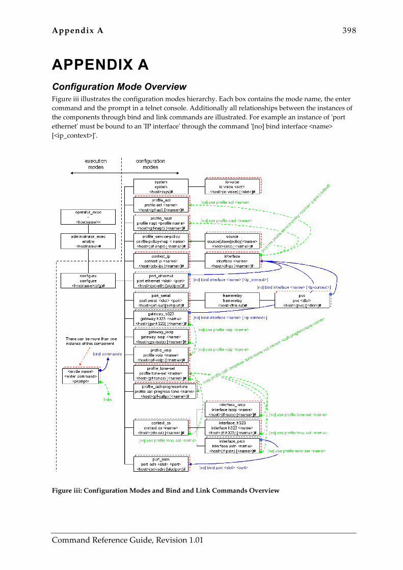
Appendix A 398
Command Reference Guide, Revision 1.01
APPENDIX A Configuration Mode Overview Figure iii illustrates the configuration modes hierarchy. Each box contains the mode name, the enter command and the prompt in a telnet console. Additionally all relationships between the instances of the components through bind and link commands are illustrated. For example an instance of 'port ethernet' must be bound to an 'IP interface' through the command '[no] bind interface <name> [<ip_context>]'.
Figure iii: Configuration Modes and Bind and Link Commands Overview
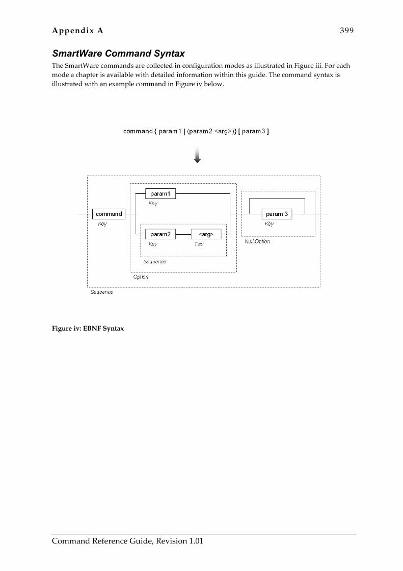
Appendix A 399
Command Reference Guide, Revision 1.01
SmartWare Command Syntax The SmartWare commands are collected in configuration modes as illustrated in Figure iii. For each mode a chapter is available with detailed information within this guide. The command syntax is illustrated with an example command in Figure iv below.
Figure iv: EBNF Syntax

Appendix B 400
Command Reference Guide, Revision 1.01
APPENDIX B Internetworking Terms and Acronyms
Abreviation Meaning
Numeric
10BaseT Ethernet Physical Medium
A
AAL ATM Adaptive Layer
ABR Available Bit Rate
AC Alternating Current
AOC Advice of Charge
ATM Asynchronous Transfer Mode
audio 3.1 ISDN Audio Service up to 3.1 kHz
audio 7.2 ISDN Audio Service up to 7.2 kHz
B
BRA Basic Rate Access
BRI Basic Rate Interface
C
CAC Carrier Access Code
CBR Constant Bit Rate
CFP Call Forwarding Procedure
CD ROM Compact Disc Read Only Memory
CDR Call Detail Record
CLEC Competitive Local Exchange Carriers
CLI Command Line Interface
CLIP Calling Line Identification Presentation
CO Central Office
CPE Customer Premises Equipment
CPU Central Processor Unit
CRC32 32 bit Cyclic Redundancy Check
D
DC Direct Current
DDI Direct Dialing In number
DHCP Dynamic Host Configuration Protocol
DSL Digital Subscriber Line
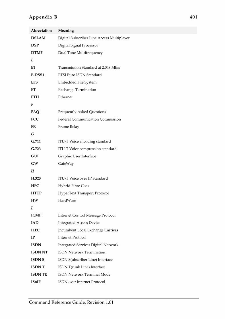
Appendix B 401
Command Reference Guide, Revision 1.01
Abreviation Meaning
DSLAM Digital Subscriber Line Access Multiplexer
DSP Digital Signal Processor
DTMF Dual Tone Multifrequency
E
E1 Transmission Standard at 2.048 Mb/s
E-DSS1 ETSI Euro ISDN Standard
EFS Embedded File System
ET Exchange Termination
ETH Ethernet
F
FAQ Frequently Asked Questions
FCC Federal Communication Commission
FR Frame Relay
G
G.711 ITU-T Voice encoding standard
G.723 ITU-T Voice compression standard
GUI Graphic User Interface
GW GateWay
H
H.323 ITU-T Voice over IP Standard
HFC Hybrid Fibre Coax
HTTP HyperText Transport Protocol
HW HardWare
I
ICMP Internet Control Message Protocol
IAD Integrated Access Device
ILEC Incumbent Local Exchange Carriers
IP Internet Protocol
ISDN Integrated Services Digital Network
ISDN NT ISDN Network Termination
ISDN S ISDN S(ubscriber Line) Interface
ISDN T ISDN T(runk Line) Interface
ISDN TE ISDN Network Terminal Mode
ISoIP ISDN over Internet Protocol
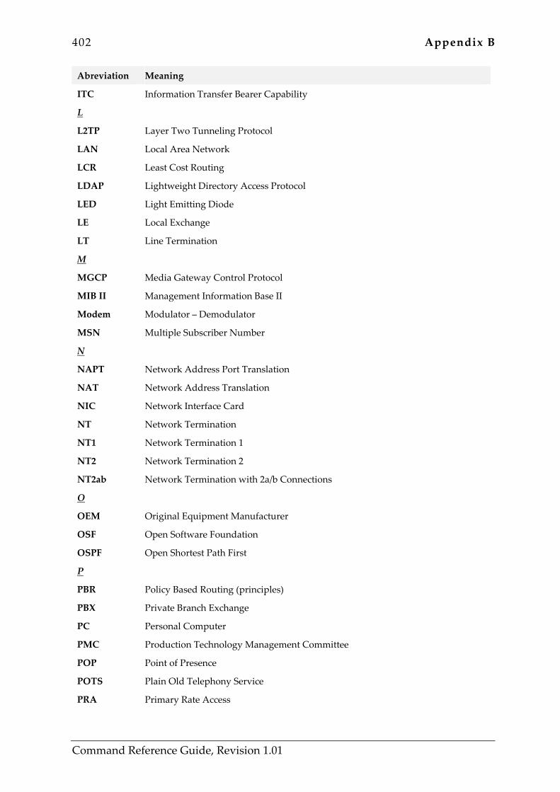
402 Appendix B
Command Reference Guide, Revision 1.01
Abreviation Meaning
ITC Information Transfer Bearer Capability
L
L2TP Layer Two Tunneling Protocol
LAN Local Area Network
LCR Least Cost Routing
LDAP Lightweight Directory Access Protocol
LED Light Emitting Diode
LE Local Exchange
LT Line Termination
M
MGCP Media Gateway Control Protocol
MIB II Management Information Base II
Modem Modulator – Demodulator
MSN Multiple Subscriber Number
N
NAPT Network Address Port Translation
NAT Network Address Translation
NIC Network Interface Card
NT Network Termination
NT1 Network Termination 1
NT2 Network Termination 2
NT2ab Network Termination with 2a/b Connections
O
OEM Original Equipment Manufacturer
OSF Open Software Foundation
OSPF Open Shortest Path First
P
PBR Policy Based Routing (principles)
PBX Private Branch Exchange
PC Personal Computer
PMC Production Technology Management Committee
POP Point of Presence
POTS Plain Old Telephony Service
PRA Primary Rate Access

Appendix B 403
Command Reference Guide, Revision 1.01
Abreviation Meaning
PRI Primary Rate Interface
PSTN Public Switched Telephone Network
pt-mpt point-to-multi point
pt-pt point-to-point
PVC Permanent Virtual Circuit
pwd Password
PWR Power
Q
QoS Quality of Service
R
RIPv1 Routing Information Protocol Version 1
RIPv2 Routing Information Protocol Version 2
RJ-45 Western Connector Type
RTM Route Table Manager
RTP Real-time Protocol
S
S1 SN-connection for Trunk Line
S2 SN-connection for Subscriber Line
SAR Segmentation and Reassembly
S-Bus Subscriber Line (Connection) Bus
SCN Switched Circuit Network
SDSL Symmetric Digital Subscriber Line
SGCP Simple Gateway Control Protocol
SME Small and Medium Enterprises
SmW SmartWare
SN SmartNode
SNMP Simple Network Management Protocol
SOHO Small Office Home Office
SONET Synchronous Optical Network
SS7 Signaling System No. 7
STM SDH Transmission at 155 Mb/s
SVC Switched Virtual Circuit
SW SoftWare
T

404 Appendix B
Command Reference Guide, Revision 1.01
Abreviation Meaning
TCP/IP Transport Control Protocol / Internet Protocol
TE Terminal Equipment
TFTP Trivial File Transfer Protocol
U
UBR Unspecified Bit Rate
UD 64 Unrestricted Data 64 kb/s
UDP User Datagram Protocol
V
VBR Variable Bit Rate
VCI Virtual Channel Identifier
VoIP Voice over Internet Protocol
VPI Virtual Path Identifier
W
WAN Wide Area Network

Appendix C 405
Command Reference Guide, Revision 1.01
APPENDIX C Used IP Ports in SmartWare Release 2.00 Component Port Description
H.323 UDP 1719 RAS for gatekeeper connection
TCP 1720 Call signaling port for H.323 (adjustable)
ISoIP UDP 1106 Voice data
UDP 1107 Voice statistics
TCP 1106 Signaling control messages
NAPT TCP 8000-15999 NAPT port range
Telnet TCP 23 TCP server port
Webserver TCP 80 TCP server port
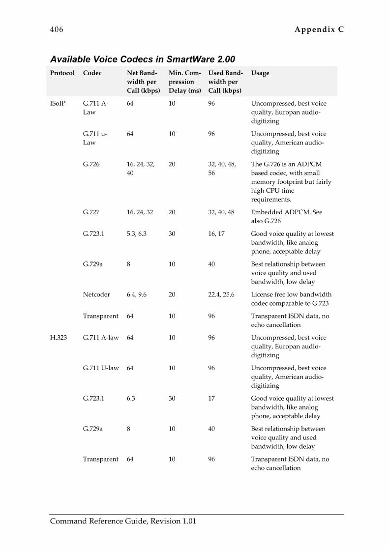
406 Appendix C
Command Reference Guide, Revision 1.01
Available Voice Codecs in SmartWare 2.00 Protocol Codec Net Band-
width per Call (kbps)
Min. Com-pression Delay (ms)
Used Band-width per Call (kbps)
Usage
ISoIP G.711 A-Law
64 10 96 Uncompressed, best voice quality, Europan audio-digitizing
G.711 u-Law
64 10 96 Uncompressed, best voice quality, American audio-digitizing
G.726 16, 24, 32, 40
20 32, 40, 48, 56
The G.726 is an ADPCM based codec, with small memory footprint but fairly high CPU time requirements.
G.727 16, 24, 32 20 32, 40, 48 Embedded ADPCM. See also G.726
G.723.1 5.3, 6.3 30 16, 17 Good voice quality at lowest bandwidth, like analog phone, acceptable delay
G.729a 8 10 40 Best relationship between voice quality and used bandwidth, low delay
Netcoder 6.4, 9.6 20 22.4, 25.6 License free low bandwidth codec comparable to G.723
Transparent 64 10 96 Transparent ISDN data, no echo cancellation
H.323 G.711 A-law 64 10 96 Uncompressed, best voice quality, Europan audio-digitizing
G.711 U-law 64 10 96 Uncompressed, best voice quality, American audio-digitizing
G.723.1 6.3 30 17 Good voice quality at lowest bandwidth, like analog phone, acceptable delay
G.729a 8 10 40 Best relationship between voice quality and used bandwidth, low delay
Transparent 64 10 96 Transparent ISDN data, no echo cancellation

Index 407
Command Reference Guide, Revision 1.01
INDEX ?, help, 22 { permit | deny } { tcp | udp | sctp }, 156 { permit | deny } icmp, 153 { permit | deny } ip, 151 About This Guide, 12 administrator, 110 Administrator Execution Mode, 69 alias, 354 Automatic medium detection, 370 banner, 112 Basic User Interface Commands, 21 bearer-capability, 269 bind gateway, 300 bind gateway isoip, 321 bind interface, 355, 364, 385 bind port, 292 BRA, 407 BRI, 407 bypass-mode, 142 call, 27 called-party, 271 calling-party, 273 call-signaling-port, 356 channel-hunting, 392 channel-numbering, 393 channel-range, 394 clear, 30 cli version, 113 clock set, 115 clock-mode, 395 clock-source, 143 codec, 301, 322, 343, 358 Command Completion, 20 Command Confirmation, 21 Command Description, 13 Command Editing, 19 Command Editing Shortcuts, 21 Command Help, 19 Command History, 20 Command Line Interface, 15 Command No Form, 20 Commands available in Administrator
Execution Mode, 70 Commands available in Configure Mode, 109 Commands available in Context CS Mode, 268 Commands available in Context IP Mode, 218 Commands available in Frame Relay Mode,
380
Commands available in Gateway H.323 Mode, 342
Commands available in Gateway ISoIP Mode, 357
Commands available in IC Voice Mode, 147 Commands available in Interface H.323 Mode,
299 Commands available in Interface ISoIP Mode,
320 Commands available in Interface Mode, 224 Commands available in Interface PSTN Mode,
291 Commands available in Operator Execution
Mode, 25 Commands available in Port Ethernet Mode,
363 Commands available in Port Serial Mode, 374 Commands available in Profile ACL Mode,
150 Commands available in Profile Call-Progress-
Tone Mode, 192 Commands available in Profile NAPT Mode,
186 Commands available in Profile Service-Policy
Mode, 160 Commands available in Profile Tone-Set
Mode, 202 Commands available in Profile VoIP Mode,
205 Commands available in PVC Mode, 384 Commands available in Source Mode, 166 Commands available in System Mode, 141 Commands available Port ISDN Mode, 391 complex-function, 275 Configuration Mode Overview, 405 configure, 116 Configure Mode, 109 context cs, 276 Context CS Mode, 268 context ip, 219 Context IP Mode, 218 copy, 71 cos, 225, 366 date, 277 DDI, 408 debug acl, 73 debug all, 75 debug call, 31

408 Index
Command Reference Guide, Revision 1.01
debug dsp, 76 debug gateway h323, 77 debug gateway isoip, 79 debug isdn, 80 debug queue statistics, 167 debug session-control, 82 debug session-router, 83 debug sntp client, 84 debug voip-data, 85 dejitter-grow-attenuation, 206, 302, 324 dejitter-grow-step, 207, 303, 325 dejitter-max-delay, 208, 304, 326 dejitter-max-packet-loss, 209, 305, 327 dejitter-mode, 210, 306, 328 dejitter-shrink-speed, 211, 307, 329 delete, 279 digit-collection, 293, 308, 330 Document Conventions, 12 Document Organization, 12 dot1q, 369 down, 396 dtmf-relay, 212, 310, 332 early-h245, 345 echo-canceller, 213, 311, 333 enable, 86 encapsulation, 368, 375, 387 end, 87 erase, 88 EU Declaration of Conformity, 3 Example Description, 13 exit, 24 fallback, 295, 312, 334 faststart, 346 fg, 34 Frame Relay Mode, 380 frame-format, 369 framerelay, 375, 381 Full Duplex, 370 gatekeeper-discovery, 347 Gateway H.323 Mode, 342 gateway h323, 349 gateway isoip, 360 Gateway ISoIP Mode, 357 Half Duplex, 370 hardware-port, 376 high-frequency, 193 high-frequency-level, 194 high-pass-filter, 214 ic voice, 148 IC Voice Mode, 147 icmp default, 187
icmp redirect accept, 226 icmp redirect send, 227 icmp router-discovery, 228 IEEE 802.1, 369 IEEE 802.3, 369 Inalp, 3, 12, 64, 113, 138 Inalp Logo, 3 interface, 229 Interface H.323 Mode, 299 interface h323, 313 interface isoip, 335 Interface ISoIP Mode, 320 Interface Mode, 223 interface pstn, 296 Interface PSTN Mode, 291 Internetworking Terms and Acronyms, 407 ipaddress, 231 jobs, 32 keepalive, 382 l2proto, 397 l3proto, 398 Legal Notice, 3 lmi-type, 383 local-inband-tones, 144 logout, 36 loop, 399 low-frequency, 195 low-frequency-level, 196 max-channels, 400 medium, 370 mode, 161 Modes and Mode Groups, 15 Modes, their Access Commands and
corresponding Prompts, 18 mtu, 233 multicast-send default-interface, 220 Navigating the CLI, 16 net, 403 Network side, 403 number-prefix, 282 off1, 197 off2, 198 on1, 199 on2, 200 operator, 118 Operator Execution Mode, 25 pcm, 149 ping, 37 point-to-point, 234 police burst-size, 169 port ethernet, 371

Index 409
Command Reference Guide, Revision 1.01
Port Ethernet Mode, 363 port isdn, 401 Port ISDN Mode, 391 port serial, 377 Port Serial Mode, 374 portaddress, 314, 336 post-filter, 215 PRA, 410 Predefined Traffic Classes, 184 PRI, 410 priority, 171 profile acl, 158 Profile ACL Mode, 150 profile call-progress-tone, 201 Profile Call-Progress-Tone Mode, 192 profile napt, 188 Profile NAPT Mode, 186 profile service-policy, 163 Profile Service-Policy Mode, 160 profile tone-set, 204 Profile Tone-Set Mode, 202 profile voip, 216 Profile VoIP Mode, 205 pvc, 388 PVC Mode, 384 q931-tunneling, 350 queue-limit, 173 random-detect, 175 ras, 351 rate, 177 received clock edge, 379 Related Commands available Source Mode,
160 reload, 89 remoteip, 315, 337 rip announce, 235 rip announce host, 237 rip announce static, 239 rip auto-summary, 241 rip default-route-value, 243 rip learn default, 245 rip learn host, 247 rip listen, 249 rip poison-reverse, 251 rip receive version, 253 rip route-holddown, 255 rip send version, 257 rip split-horizon, 259 rip supply, 261 route, 221 routing, 297, 316, 338
session-control close, 90 set ip dscp, 178 set ip precedence, 179 set ip tos, 180 set layer2 cos, 181 share, 182 show, 91 show accounts, 93 show call, 39 show clock, 40 show context cs, 94 show crc, 95 show dsp, 41 show framerelay, 42 show gateway h323, 96 show gateway isoip, 97 show history, 43 show ip interface, 44 show ip route, 46 show isdn, 98 show log, 48 show log supervisor, 99 show napt interface, 50 show port ethernet, 52 show port isdn, 53 show port serial, 54 show profile acl, 101 show profile call-progress-tone, 55 show profile napt, 102 show profile service-policy, 103 show profile tone-set, 57 show profile voip, 59 show rip, 60 show service-policy, 62, 104 show session-control, 105 show snmp, 106 show sntp-client, 108 show uptime, 63 show version, 64 show version cli, 66 shutdown, 283, 352, 361, 372, 378, 390 silence-compression, 217, 317, 339 smart-disconnect, 402 SmartNode, 3, 12, 24, 64, 135, 136, 138, 154,
171, 178, 179, 180, 181, 184, 185, 186, 192, 202, 205, 218, 223, 268, 291, 299, 320, 363, 374, 379, 380, 383, 385, 388, 391, 410
SmartNode Hardware Installation Guide., 12 SmartView, 3 SmartWare Command Syntax, 406 snmp community, 120

410 Index
Command Reference Guide, Revision 1.01
snmp host security-name, 121 snmp target security-name, 122 sntp-client, 123 sntp-client anycast-address, 124 sntp-client gmt-offset, 125 sntp-client local-clock-offset, 126 sntp-client local-port, 127 sntp-client operating-mode, 128 sntp-client poll-interval, 130 sntp-client server, 131 Software Configuration Guide, 12 source, 184 Source Mode, 166 standard, 369 static, 190 synchronize-to-isdn-time, 145 system, 146 system contact, 132 system hostname, 133 system location, 134 System Mode, 141 System Prompt, 15 system provider, 135
system subscriber, 136 system supplier, 138 time, 285 translation-table, 287 transmit-data-on-edge, 379 Typographical Conventions, 13 uni-side, 403 up, 404 use profile acl, 263 use profile napt, 265 use profile service-policy, 266 use tone-set-profile, 288, 298, 318, 340 use voip-profile, 353, 362 User side, 403 usr, 403 vlan, 373 VLAN group, 373 Voice Codecs, 413 voice-volume, 319, 341 webserver, 140 weekday, 289 who, 68


