74
ANR-06-RGCU-002 COMMUNIC Deliverables L3 : Functional Program of the Digital Model Version 10/12/2010 Collaboration using the Multi-Purpose Digital Model and Concurrent Engineering

ANR-06-RGCU-002
COMMUNICDeliverables
L3 : Functional Program of the Digital Model
Version 10/12/2010
Collaboration using the Multi-Purpose Digital Model and Concurrent Engineering

Presentation of deliverable L3
L3 : Programme fonctionnel de la maquette numérique Page 2 of 74
Deliverables Version 10/12/2010
Contents page Présentation of deliverable L3 .................. .............................................................. 3
COMMUNIC: one memo, three deliverables ............ .......................................................... 3
Content of deliverable L3 chapters ................ ................................................................... 4
Reading Aids ...................................... ................................................................................. 5
A - Context ....................................... ......................................................................... 7
A1 - Organizational context ....................... ......................................................................... 8
A2 - Discipline-specific context .................. ..................................................................... 10
A3 - Projects involved ............................ .......................................................................... 13
B - Features ...................................... ...................................................................... 17
Introduction ...................................... ................................................................................. 18
B1 - Modeling ..................................... ............................................................................... 19
B2 - Exchange ..................................... .............................................................................. 22
B3 - Calculate and simulate ....................... ...................................................................... 23
B4 - Manage ....................................... ............................................................................... 25
B5 - View ......................................... ................................................................................... 27
B6 - Optimize ..................................... ................................................................................ 29
C - Architecture .................................. .................................................................... 31
C1- Global architecture ........................... ......................................................................... 32
C2 - Distribution of features ..................... ........................................................................ 37
C3 - Assessment of the architecture ............... ................................................................ 39
D - Software ...................................... ...................................................................... 41
Introduction ...................................... ................................................................................. 42
D1 - CEP management tools ......................... ................................................................... 42
D2 - CEP synthesis tools .......................... ........................................................................ 47
D3 - Exchange platform ............................ ........................................................................ 53
D4 - Discipline-specific tools .................... ....................................................................... 55
D5 - Assessment of tools .......................... ....................................................................... 56
E - Data model .................................... .................................................................... 57
Introduction ...................................... ................................................................................. 58
E1 - General characteristics of a data model ...... ............................................................ 59
E2 - The COMMUNIC data model ...................... ............................................................... 61
F - Roadmap to a COMMUNIC exchange standard ....... ...................................... 65
Introduction ...................................... ................................................................................. 66
F1 - Use of existing standards .................... ..................................................................... 68
F2 - Toolkit ...................................... .................................................................................. 73

Presentation of deliverable L3
L3 : Programme fonctionnel de la maquette numérique Page 3 of 74
Deliverables Version 10/12/2010
Presentation of deliverable L3
COMMUNIC: one memo, three deliverables
The COMMUNIC project
The research project is called COMMUNIC, for COllaboration par la Maquette
Multi-Usages Numérique et l’Ingénierie Concourante (Collaboration using the
Multi-Purpose Digital Model and concurrent engineering). It was selected by ANR (Agence Nationale de la Recherche) following a call for proposals in 2006.
This project was approved by the ADVANCITY Competitiveness cluster.
The project was begun in 2007 and lasted 3 years.
Object Its purpose is to foster the development of collaborative work in infrastructure projects through the use of an information model (IM).
Partners The project partners are:
• Engineering: EGIS and Setec TPI.
• Contractors Bouygues Construction, Vinci Construction France, Eiffage TP.
• Research Centers and Academic Partners: CSTB, the Ecole Polytechnique's Management Research Center, LCPC, University Paris Est, and IREX.
Overview of work done by COMMUNIC
The research conducted under the COMMUNIC research project is the object of this memo, which summarizes the project's progress and results.
To make this thesis more practical to use, we have completed it with three deliverables that:
• describe our work more fully,
• provide unique perspectives on our conclusions.
COMMUNIC project deliverables
The table below shows the 3 deliverables:
Deliverable Title Mission Contents
L1 Global model
Describe the technological and
organizational model which will support collaborative work through a shared digital model
Overall description of the model.
Expected values and uses.
Structuring of information and its circulation.
Adaptations of the organizations.
Redistribution of responsibilities.
L2
Recommendations
for
implementation of
the digital model
List of recommendations for stakeholders.
Tools.
Projects.
Companies.
Construction sector.
Change management.
L3 Functional
program of the
digital model
Aimed at software publishers who will have to adapt or create software allowing use of the digital model.
Projects concerned.
Proposed system with the expected features, architecture, data model and standardization.
Copy editing and final proofreading was provided by the Artecomm company using MRS, l'Écrit Intellisible®.
Presentation of deliverable L3
L3 : Programme fonctionnel de la maquette numérique Page 4 of 74
Deliverables Version 10/12/2010
Content of deliverable L3 chapters
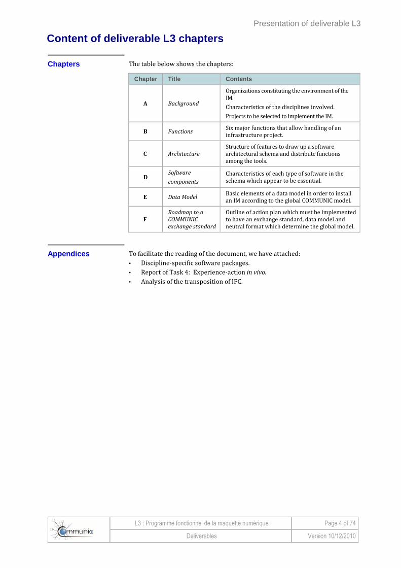
Chapters The table below shows the chapters:
Chapter Title Contents
A Background
Organizations constituting the environment of the IM.
Characteristics of the disciplines involved.
Projects to be selected to implement the IM.
B Functions Six major functions that allow handling of an infrastructure project.
C Architecture
Structure of features to draw up a software architectural schema and distribute functions among the tools.
D Software
components
Characteristics of each type of software in the schema which appear to be essential.
E Data Model Basic elements of a data model in order to install an IM according to the global COMMUNIC model.
F
Roadmap to a
COMMUNIC
exchange standard
Outline of action plan which must be implemented to have an exchange standard, data model and neutral format which determine the global model.
Appendices To facilitate the reading of the document, we have attached:
• Discipline-specific software packages.
• Report of Task 4: Experience-action in vivo.
• Analysis of the transposition of IFC.
Presentation of deliverable L3
L3 : Programme fonctionnel de la maquette numérique Page 5 of 74
Deliverables Version 10/12/2010
Reading Aids
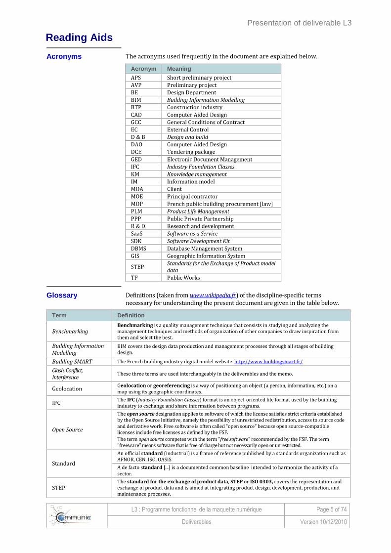
Acronyms The acronyms used frequently in the document are explained below.
Acronym Meaning
APS Short preliminary project AVP Preliminary project BE Design Department BIM Building Information Modelling
BTP Construction industry CAD Computer Aided Design GCC General Conditions of Contract EC External Control D & B Design and build
DAO Computer Aided Design DCE Tendering package GED Electronic Document Management IFC Industry Foundation Classes KM Knowledge management
IM Information model MOA Client MOE Principal contractor MOP French public building procurement [law] PLM Product Life Management
PPP Public Private Partnership R & D Research and development SaaS Software as a Service
SDK Software Development Kit
DBMS Database Management System GIS Geographic Information System
STEP Standards for the Exchange of Product model
data
TP Public Works
Glossary Definitions (taken from www.wikipedia.fr) of the discipline-specific terms necessary for understanding the present document are given in the table below.
Term Definition
Benchmarking Benchmarking is a quality management technique that consists in studying and analyzing the management techniques and methods of organization of other companies to draw inspiration from them and select the best.
Building Information
Modelling BIM covers the design data production and management processes through all stages of building design.
Building SMART The French building industry digital model website. http://www.buildingsmart.fr/
Clash, Conflict,
Interference These three terms are used interchangeably in the deliverables and the memo.
Geolocation Geolocation or georeferencing is a way of positioning an object (a person, information, etc.) on a map using its geographic coordinates.
IFC The IFC (Industry Foundation Classes) format is an object-oriented file format used by the building industry to exchange and share information between programs.
Open Source
The open source designation applies to software of which the license satisfies strict criteria established by the Open Source Initiative, namely the possibility of unrestricted redistribution, access to source code and derivative work. Free software is often called "open source" because open source-compatible licenses include free licenses as defined by the FSF. The term open source competes with the term "free software" recommended by the FSF. The term "freeware" means software that is free of charge but not necessarily open or unrestricted.
Standard
An official standard (industrial) is a frame of reference published by a standards organization such as AFNOR, CEN, ISO, OASIS
A de facto standard [...] is a documented common baseline intended to harmonize the activity of a sector.
STEP The standard for the exchange of product data, STEP or ISO 0303, covers the representation and exchange of product data and is aimed at integrating product design, development, production, and maintenance processes.

L3 : Programme fonctionnel de la maquette numérique Page 6 of 74
Deliverables Version 10/12/2010
This page left blank intentionally

A - Context
L3 : Programme fonctionnel de la maquette numérique Page 7 of 74
Deliverables Version 10/12/2010
A - Context
A1 - Organizational context ....................... .................................................................... 8
Contractual schemas for procurement ............... ........................................................................ 8
Development of integrated projects ................ ...................................................................... 8
Acceleration of data exchange process ............. ................................................................... 9
Organization of the sector ....................... .............................................................................. 9
A2 - Discipline-specific context .................. ................................................................ 10
2D/3D Design ...................................... ....................................................................................10
Exchange media..................................... ................................................................................11
Specific needs of geotechnical engineering ........ ...............................................................11
A large array of software packages ................ .....................................................................12
Feedback from ..................................... ..................................................................................12
Task 4 ............................................ ..........................................................................................12
A3 - Projects involved ............................ ..................................................................... 13
Criteria for selecting projects ................... ............................................................................13
Large complex projects ............................ ............................................................................14
The smallest projects ............................. ...............................................................................15
Summary ........................................... ......................................................................................15

A - Context
L3 : Programme fonctionnel de la maquette numérique Page 8 of 74
Deliverables Version 10/12/2010
A1 - Organizational context
Several factors have come about lately to "change things" and promote the use of IM tools.
Contractual schemas for procurement
Major infrastructure projects (road, rail, industrial) are currently implemented by 3 types of contracts shown below.
Type 1: Design - Bid - Build
In Type 1, "Design - Bid - Build", the design is done upstream.
The construction company then determines the most suitable methods to execute a given project at lowest cost. Work contracts can even be assigned in separate
batches (metal, concrete, etc.).
Type 2: Design & Build
Type 2 is called "Design & Build" (D & B). It brings together the whole chain from design to completion with a single contractor.
Type 3: Concessions or PPP
In Type 3, "concessions" or "PPP", the contractor is all at once client, designer, builder and operator for a fixed term. We also talk about BOT (Build - Operate - Transfer). This is the most integrated type of design.
At the end of the concession, the concessionaire returns the structure to the concessionary authority.
Development of integrated projects
Types 2 and 3 are rapidly gaining
popularity...
The first type of contract is most prevalent. However, Types 2 and 3 are rapidly gaining popularity, and are chosen to handle the biggest
infrastructure projects (highways, railroads, stadiums, various complexes, etc.).
... and are most favorable to concurrent
engineering
In the classical Type 1 contract, changes in the project are reflected on a set of 2D drawings. This requires a long process of requests for change and approvals, leading to high costs and long completion times.
Types 2 and 3, however, bring design, choice of construction methods, equipment and operating modes together in the same entity. In integrated design (contract Types 2 and 3), studies may be anticipated, and the services and subcontractors become involved more upstream. They are therefore most favorable to the application of an integrated tool of the IM type.
A - Context
L3 : Programme fonctionnel de la maquette numérique Page 9 of 74
Deliverables Version 10/12/2010
A1 - Organizational context (Continued)
Accelerati on of data exchange process
Today, the acceleration of exchanges means a large volume of information (text or drawing files) is being carried by e-mail.
A need for fluidity of exchanges...
E-mail systems may be saturated. The ever-increasing volume of information therefore also creates a greater need for fluidity of exchanges.
... partially handled by EDM ...
On major infrastructure projects (highways, high speed rail lines, etc.), the introduction of an EDM simplified management, and channeled the flow of information. However, it did not provide an answer to the question of how to represent the project in terms of manipulable and parametric objects.1
... and addressed by the IM
The growth of Type 2 and 3 contracts is a good opportunity for the adoption of an IM tool, which alone is capable of ensuring an integrated approach in a limited time with a multi-criteria analysis of the performance required by the specifications.
Organization of the sector
In industry (in particular automobiles, aerospace, shipbuilding), the design process is organized by a powerful stakeholder who chooses his tools and provides them to partners and subcontractors.
The diversity of stakeholders was a
hindrance to the sharing of tools
In construction, there are very many stakeholders such as clients, engineering firms, companies or suppliers. None of them is in a position to choose a tool or a standard and impose it on the others.
They therefore share no common tools apart from the basic office software packages on the market and general design software. This also explains the large numbers of software packages used, a number that is in fact an obstacle to the emergence of common tools.
1 A parametric modeling system is a system that records not only the explicit geometry of the design object ("parametric object" or "'current instance),
but also a mechanism to reassess when the parameters are modified ("design process"," constructive gestures "or "parametric specification").
http://www.lisi.ensma.fr/fr/equipes/idd/geometrieparametrique.html
A - Context
L3 : Programme fonctionnel de la maquette numérique Page 10 of 74
Deliverables Version 10/12/2010
A2 - Discipline-specific context
2D/3D Design
Overview The installation base of 2D or 3D design software covers several thousands of
licenses in France. However, there are only a few IM products in design departments, engineering firms and companies involved in major linear infrastructure projects. The stakeholders in the construction industry (architects, engineering firms, etc.), on the other hand, have commercially-available tools suited to their profession.
Civil engineering drawings are mostly prepared using general-purpose
software packages, mainly Autocad (published by Autodesk). Their use may or may not be accompanied by additional "discipline-specific" applications for road alignments, for example, for drawings of reinforcements in concrete, or for the layout of steel frames. This specialized software brings together all the expertise of a domain, and must be preserved or duplicated in the new tool.
Many businesses still design in 2D
The current design tools have been designed to automate the old methods of design, which were manual.
Some have therefore exploited the linear characteristic of certain infrastructure (roads, railways, etc.), and the design is still "3 times 2D". They work first on the alignment, then fit on a longitudinal profile, and finally attach cross sections. Each step is thus done in 2D.
For other infrastructure projects, calculations are sometimes done on a surface (no preferred horizontal axis). The design elements are always longitudinal profiles, cross sections, and cross-sectional profiles.
Methods of execution have been adapted to these design principles with, for example, setup of axes, then the characteristic points of cross sections. The fields designed in this way are thus, for example:
• geometry,
• earthworks,
• drainage,
• pavement,
• longitudinal equipment.
Some designs are done with
3D objects
Some disciplines have had to manipulate 3D objects. The tools that were developed correspond more to 3D design. This applies, for example, to:
• structures,
• operating buildings,
• some equipment of more industrial type.
See the geometric result
of design in 3D
The designer always wanted to view his design. Without mentioning physical mock-ups, which were rarely employed, he used:
• drawings,
• perspective drawings,
• automatic 3D views that many software packages have incorporated into their design features,
• virtual models which some providers have been offering in real time for over a decade.
This 3D view of the structures designed is not to be confused with the design of 3D volumetric objects to which information is attached. It is this design which the IM can fully exploit.
A - Context
L3 : Programme fonctionnel de la maquette numérique Page 11 of 74
Deliverables Version 10/12/2010
A2 - Discipline-specific context (Continued)
2D/3D Design (Continued)
Integration of environmental data
In addition to the usual bills of quantities or calculations of strength of materials, current projects should incorporate environmental parameters from the initial design stage. For example: • carbon footprint • thermal performance, • acoustic performance, • energy performance, • impacts on biodiversity, • land compensation.
These parameters must be quantified and may be used throughout the life of the structure. Therefore the IM must manage data which allow these assessments.
Moreover, it is desirable to have the most realistic virtual representation possible. It integrates many components with the possibility of simulating / optimizing the functioning of the project during the construction phase or the operation phase.
This leads to a real monitoring of the structure throughout its life, which is the very definition of PLM.
Exchange media
Outputs are not reused from one
discipline to another
The design process is undertaken specialty by specialty ("sector by sector"), with little reuse of the basic geometry or outputs from one discipline to another. For example, geometry is not connected to:
• planning tools to visualize the phases of the work,
• price study software (directly) even though it may include discipline-specific tools for calculating quantities.
Information exchange
is done by documents...
The documents supporting the exchange of information are: • drawings, • calculation notes, • reports, • classifications.
They can be on paper or in electronic form. They have the disadvantage that they group many different items of information. This makes the approval process very cumbersome each time there is a new version. Indeed, all the information in the document must be re-validated, including unmodified information.
... the only ones to be managed
collaboratively
The only collaborative tool which is frequently used is the EDM. It is suited to document exchange.
The IM must be used to manage exchanges of information.
Specific needs of geotechnical engineering
Civil engineering works (bridges, linear infrastructure such as roads, rail or river, dams, ports) depend closely, as to their design and choice of construction, on the geological, hydrogeological and geotechnical context of the site where they are located.
A strategic element of
design
A good knowledge of the geotechnical model is a strategic element for the technical and economic success of the project. This is a very important feature of the infrastructure projects the IM helps manage.

A - Context
L3 : Programme fonctionnel de la maquette numérique Page 12 of 74
Deliverables Version 10/12/2010
A2 - Discipline-specific context (Continued)
Specific needs of geotechnical engineering (Continued)
Model uncertainties
and risks
A methodology should make it possible to develop a geotechnical model with control of uncertainties and contingencies. This model makes the geotechnical risk of the project a measurable quantity.
It is built from various data: • geological maps, • visual surveys, • boreholes, • tests.
This data is then processed by statistical tools, interpolations and extrapolations to model the terrain and its characteristics.
Representations suited to the use
The designer and the client need a clear picture of the spatial organization of
materials constituting the subsoil, as well as their interactions and their characteristics.
Depending on the use to which he wants to put the geotechnical model, each stakeholder uses drawings, cross sections, longitudinal profiles and many tables.
3D object models provided by the IM must be parameterized and specific to each use, which constitute so many systems: • view by nature of material, • extraction conditions, • conditions of reuse, • capacity, • deformability and compressibility, • hydrogeological network.
The organization of these different views of the model is a challenge for the IM.
A large array of software packages
The IM can exchange data with applications in disciplines from all areas of the sector. There are many of these software packages, which meet the specific needs of each discipline.
Application software must evolve to a
common standard
When software is systematically complementary, publishers have developed gateways to exchange data and results. Given the number of software packages, it is unrealistic to develop and especially to maintain gateways for all desired exchanges .
The challenge is therefore to develop a neutral standard shared by the profession, whether it be a data model or an exchange format.
Inventory of application software
Making an inventory of all application software packages used does not contribute to the definition of the global model, architecture or data model proposed by COMMUNIC. Adaptation is done on a case-by-case basis for each program on the initiative of the publisher.
To enable the reader to assess the diversity, a list of available software packages has been prepared. It is given in the appendix.
Feedback from
Task 4
We have, in Task 4, conducted experiments on the implementation of the global model. They allowed us to establish: • The extreme difficulty of interconnecting existing software packages. • Weaknesses in design / authoring software for generating IM objects and
attaching information to them. The report on this Task 4 spells out our findings. It is attached to this deliverable L3.
A - Context
L3 : Programme fonctionnel de la maquette numérique Page 13 of 74
Deliverables Version 10/12/2010
A3 - Projects involved
Criteria for selecting projects
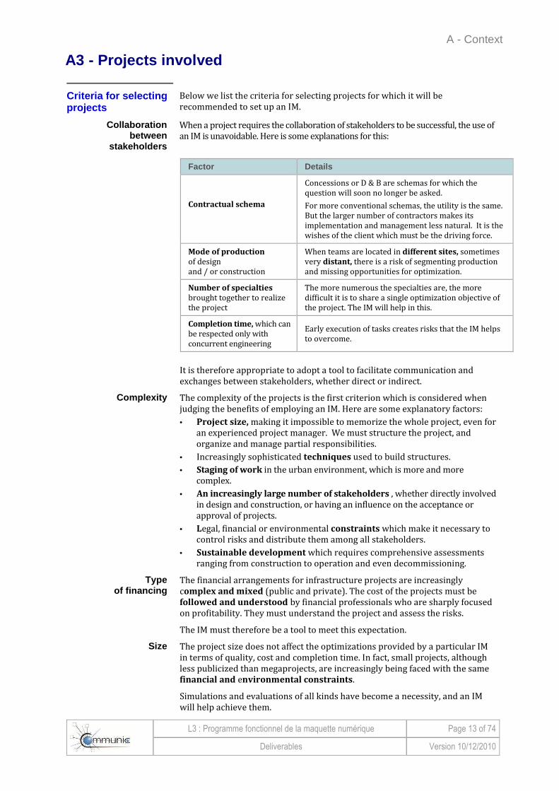
Below we list the criteria for selecting projects for which it will be recommended to set up an IM.
Collaboration between
stakeholders
When a project requires the collaboration of stakeholders to be successful, the use of an IM is unavoidable. Here is some explanations for this:
Factor Details
Contractual schema
Concessions or D & B are schemas for which the question will soon no longer be asked.
For more conventional schemas, the utility is the same. But the larger number of contractors makes its implementation and management less natural. It is the wishes of the client which must be the driving force.
Mode of production of design and / or construction
When teams are located in different sites, sometimes very distant, there is a risk of segmenting production and missing opportunities for optimization.
Number of specialties brought together to realize the project
The more numerous the specialties are, the more difficult it is to share a single optimization objective of the project. The IM will help in this.
Completion time, which can be respected only with concurrent engineering
Early execution of tasks creates risks that the IM helps to overcome.
It is therefore appropriate to adopt a tool to facilitate communication and exchanges between stakeholders, whether direct or indirect.
Complexity The complexity of the projects is the first criterion which is considered when judging the benefits of employing an IM. Here are some explanatory factors:
• Project size, making it impossible to memorize the whole project, even for an experienced project manager. We must structure the project, and organize and manage partial responsibilities.
• Increasingly sophisticated techniques used to build structures.
• Staging of work in the urban environment, which is more and more complex.
• An increasingly large number of stakeholders , whether directly involved in design and construction, or having an influence on the acceptance or approval of projects.
• Legal, financial or environmental constraints which make it necessary to control risks and distribute them among all stakeholders.
• Sustainable development which requires comprehensive assessments ranging from construction to operation and even decommissioning.
Type of financing
The financial arrangements for infrastructure projects are increasingly complex and mixed (public and private). The cost of the projects must be followed and understood by financial professionals who are sharply focused on profitability. They must understand the project and assess the risks.
The IM must therefore be a tool to meet this expectation.
Size The project size does not affect the optimizations provided by a particular IM in terms of quality, cost and completion time. In fact, small projects, although less publicized than megaprojects, are increasingly being faced with the same financial and environmental constraints.
Simulations and evaluations of all kinds have become a necessity, and an IM will help achieve them.
A - Context
L3 : Programme fonctionnel de la maquette numérique Page 14 of 74
Deliverables Version 10/12/2010
A3 - Projects involved (Continued)
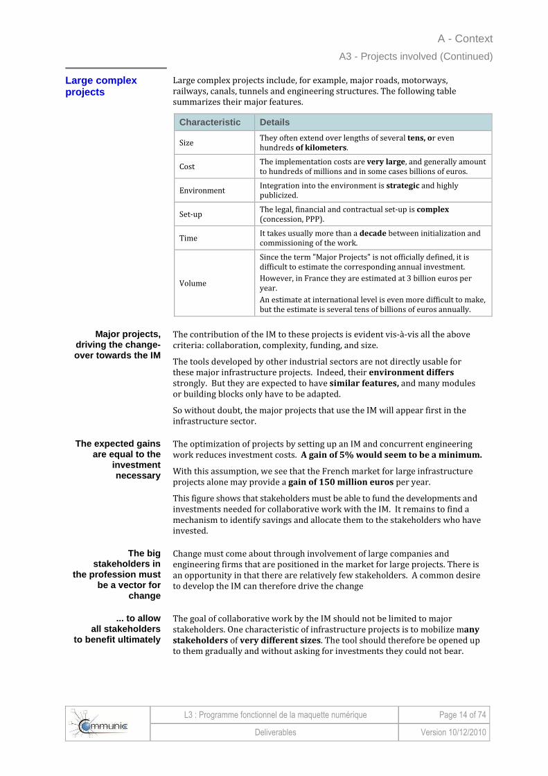
Large complex projects
Large complex projects include, for example, major roads, motorways, railways, canals, tunnels and engineering structures. The following table summarizes their major features.
Characteristic Details
Size They often extend over lengths of several tens, or even hundreds of kilometers.
Cost The implementation costs are very large, and generally amount to hundreds of millions and in some cases billions of euros.
Environment Integration into the environment is strategic and highly publicized.
Set-up The legal, financial and contractual set-up is complex (concession, PPP).
Time It takes usually more than a decade between initialization and commissioning of the work.
Volume
Since the term "Major Projects" is not officially defined, it is difficult to estimate the corresponding annual investment.
However, in France they are estimated at 3 billion euros per year.
An estimate at international level is even more difficult to make, but the estimate is several tens of billions of euros annually.
Major projects, driving the change-over towards the IM
The contribution of the IM to these projects is evident vis-à-vis all the above criteria: collaboration, complexity, funding, and size.
The tools developed by other industrial sectors are not directly usable for these major infrastructure projects. Indeed, their environment differs strongly. But they are expected to have similar features, and many modules or building blocks only have to be adapted.
So without doubt, the major projects that use the IM will appear first in the infrastructure sector.
The expected gains are equal to the
investment necessary
The optimization of projects by setting up an IM and concurrent engineering work reduces investment costs. A gain of 5% would seem to be a minimum.
With this assumption, we see that the French market for large infrastructure projects alone may provide a gain of 150 million euros per year.
This figure shows that stakeholders must be able to fund the developments and investments needed for collaborative work with the IM. It remains to find a mechanism to identify savings and allocate them to the stakeholders who have invested.
The big stakeholders in
the profession must be a vector for
change
Change must come about through involvement of large companies and engineering firms that are positioned in the market for large projects. There is an opportunity in that there are relatively few stakeholders. A common desire to develop the IM can therefore drive the change
... to allow all stakeholders
to benefit ultimately
The goal of collaborative work by the IM should not be limited to major stakeholders. One characteristic of infrastructure projects is to mobilize many
stakeholders of very different sizes. The tool should therefore be opened up to them gradually and without asking for investments they could not bear.

A - Context
L3 : Programme fonctionnel de la maquette numérique Page 15 of 74
Deliverables Version 10/12/2010
A3 - Projects involved (Continued)
The smallest projects
The smallest projects are obviously the most numerous. The following table summarizes their major features.
Characteristic Details
Size They relate either to smaller structures, or improvements to structures in service.
Cost
These projects, which can cost from several million to tens of millions of euros, are obviously the most numerous and probably represent 80-90% of total investments (several tens of billions of euros per year in France).
Complexity Their complexity is nevertheless often large, especially for structures in service.
Stakeholders Stakeholders in these markets are actually quite numerous and vary in size, but are often small (SME).
Slower, but inevitable,
penetration of the IM
The size of each project is not, in principle, sufficient to justify the necessary investments to implement an IM.
However, when the tools and methods have been developed for large
projects, there is no doubt they will be used for virtually all of these projects.
The profession will have to:
• disseminate methods;
• train users;
• make the IM tool accessible to all at a cost in line with the savings on each project.
Summary
All futures markets concerned
All infrastructure markets are therefore concerned with the development of the IM. We must have this goal in mind to design tools and lead change.
Gradual penetration It is likely that the distribution of IM will go through steps to limit the risks taken:
• Start with limited parts of a large project with the involvement of major project stakeholders (client, main engineering firm, main builder).
• Extend it to the whole of a large project with the involvement of the same major stakeholders.
• Extend it to all stakeholders in a large project.
• Use the IM on increasingly modest projects.
Slow, but urgent change
This change has in some ways already begun with the change-over of software to 3D and the development of D&B, PPP and concessions.
The use of a shared IM on an entire major infrastructure project could be a reality in the next 5 years.
The progressive dissemination of the IM into most projects should come about in the next decade.

A - Context
L3 : Programme fonctionnel de la maquette numérique Page 16 of 74
Deliverables Version 10/12/2010
This page left blank intentionally

B - Features
L3 : Programme fonctionnel de la maquette numérique Page 17 of 74
Deliverables Version 10/12/2010
B - Features
Introduction ...................................... ............................................................................ 18 Relevant features ................................. ..................................................................................18 An inventory to be allocated in an architectural sc hema .............................................. ....18
B1 – Modeling ..................................... ......................................................................... 19 3D authoring software packages .................... .....................................................................19 Authoring software in infrastructure projects ..... ...............................................................20 Real-time visualization of design objects ......... ..................................................................20 Objects to standardize ............................ ............................................................................. 20 Other functions to model .......................... ............................................................................21 Software performance .............................. .............................................................................22 Parent / child links ............................. .................................................................................. 22
B2 - Exchange ..................................... ......................................................................... 22 Export and import . ...............................................................................................................22 ... using the exchange platform ................... .........................................................................22
B3 - Calculate and simulate ....................... ............................................................... 23 Use the data ...................................... ......................................................................................23 Simulate earth movements .......................... .........................................................................23 Other simulation software packages ................ ...................................................................23 Strongly iterative simulations .................... ......................................................................... 23 Manage iterative simulations ...................... ..........................................................................24 Link the geometric model with analytical models ... ...........................................................24 Pre-processor / post-processor .................... ...................................................................... 24
B4 - Manage ....................................... ......................................................................... 25 A carefully managed IM ............................ .............................................................................25 Quality of imports and exports .................... .........................................................................25 Instill confidence by protected private data ...... .................................................................25 Permanent hosting of IM ........................... ............................................................................26 A main model, and synchronized secondary models ... .....................................................26
B5 - View ......................................... ............................................................................. 27 Visualization tool complementary to viewers of vari ous disciplines ..............................27 Visualizations customized to each stakeholder ..... ............................................................27 Escalation and the potential of visualization ..... ................................................................ 28 Basic features .................................... ....................................................................................28 Desirable advanced features ....................... .........................................................................28
B6 - Optimize ..................................... ........................................................................... 29 Optimization means combining the basic features ... ........................................................ 29 The IM simplifies the work of the expert ... ...... .................................................................. 29 ... but it is always the expert who does the optimi zing .............................................. ........29

B - Features
L3 : Programme fonctionnel de la maquette numérique Page 18 of 74
Deliverables Version 10/12/2010
Introduction
Relevant features Consistent with the presentation of the functions of the collaborative environment described in deliverable L2-A, we now specify the features that underlie the global model.
These features all have the objective of coordinating and sharing project information. Regardless of their assignment to particular software, we'll start by listing them and describing them.
Six groups of features of the
global model
We have grouped the features around six objectives of the global model:
• model,
• exchange,
• calculate and simulate,
• manage,
• view,
• optimize.
These six goals structure the remainder of this chapter.
An inventory to be distributed in an architectur al schema
The architectural schema of features that leads to the architecture of the software packages will be presented in Chapters C and D. Also, the features of the six goals outlined above will be cross-referenced with these schemas.

B - Features
L3 : Programme fonctionnel de la maquette numérique Page 19 of 74
Deliverables Version 10/12/2010
B1 – Modeling
3D authoring software
The action of authoring (or modeling) is performed using 3D authoring
software (or a 3D modeler), known as an "authoring tool " .
Purpose and use
This is a computer application used to create 3D representations composed of complex shapes or 3D objects, from basic primitives or analytical definition.
3D authoring software is used: • In computer-assisted industrial design. • By graphic designers who draw scenes to create animations,
presentations or virtual reality environments.
Handling of basic shapes
They are essentially based on the manipulation of basic shapes: cubes, spheres, cones, and even Bezier curves or NURBS2 (Non-Uniform Rational Basis Splines). They generally offer a toolkit that can model these basic shapes to obtain more complex shapes.
Transformation These authoring software packages can be simple geometric transformations. They can also perform more complex transformations, making it possible to change parts of the shape, cut them, or twist them in all directions.
They may operate on other attributes such as: • the texture of the object, • color, • how it transforms the light • the owner of the object, • creation date,
• status in the various validation or approval flows.
Moreover, they describe links between different objects, for example: • membership or dependence, • contact or distance to be respected.
3D modeling: a gradual, iterative
process
3D modeling is a gradual, iterative process. It adapts to the level of
development of the current phase of study, from the first sketches based on simple geometric representations of volumes and outline dimensions (parallelepipeds), to the details of some of the most sophisticated manufactured accessories (safety barriers, street lamps, etc.).
Authoring software is an application with a high human added value, although it is assisted by computer. With such software, the designer brings to the project all his knowledge, reasoning, imagination and knowledge.
2 NURBS : Mathematical representations of 3D geometry that can accurately describe any shape from a simple 2D line, circle, arc or curve to a surface or a 3D organic solid of very complex free form (http://www.fr.rhino3d.com/nurbs.htm).

B - Features
L3 : Programme fonctionnel de la maquette numérique Page 20 of 74
Deliverables Version 10/12/2010
B1 – Modeling (Continued)
Authoring software for infrastructure projects
The 3D software must include the basic modeling functions: • creation of axes, • representation and manipulation of natural terrain (pegging out of
points, contours, triangulation, etc.) • advanced features necessary for environmental management essential
to the project, • representation of geological strata (by extrapolation of known points),
since a project is rarely "above" the terrain.
As part of the design of infrastructure projects, some phases of creation are expressed only in 2D (in particular for some plan views of complex curves, such as spirals). We must therefore maintain a strong interaction between a 3D object and its 2D representations (plan views, elevations and cross-sections).
Real time visualization in design of objects
The modeling of complex projects is imposes a large dependency of:
• objects with one another,
• views with one another.
The links and dynamic relationships between the objects and views of the work must be kept and updated in real time.
This makes it possible to work on several axes simultaneously, and immediately measure the impact of the design or optimization on the entire project or sub-project under study.
Objects to standardize
Working in "object" mode means manipulating the elementary components essential for all infrastructure projects.
Level 1 object: reference building b.1.1
s Level 2 objects, of different types: access ways, foundations, vertical structures, road, deck.
Figure B1-1: Structuring into objects

B - Features
L3 : Programme fonctionnel de la maquette numérique Page 21 of 74
Deliverables Version 10/12/2010
B1 – Modeling (Continued)
Objects to standardize (Continued)
Examples of discipline-specific
objects
Here are some examples of discipline-specific objects. Their exact definition could be the subject of another research project. Indeed, there is now no
complete standard describing these specific objects, except for the part concerned with bridges described in the IFC-Bridge standard.
To define Specific objects
Engineering structure (over- and underpasses tunnel, cut & cover, roundabout)
Pile
Deck
Segment (and the need for sections perpendicular to the slope of the axis)
Earthworks Cutting / Embankment
Drainage
Platforms Subgrades
Pavements
Sanitation
Basins
Hydraulic Structures
Natural watershed
Buildings
Toll plaza
Service Center
Rest Areas
Refuge
Catalogs of standard objects can also be prepared by equipment suppliers in order to allow direct insertion.
These families of objects must be validated or supplemented to satisfy the modeling protocol selected.
Other functions to model
Beyond modeling the geometry of the project, other functions must be integrated into the 3D authoring software:
Function Features
Represent the phasing
of construction
Animated representation of the entire construction project, with the sequencing of the various construction sites and major phases of construction.
Successive representations of the same structure over time.
Representations of temporary diversions and bypasses.
Represent objects with the level of development imposed by the design phase
Several representations of the same object.
Opportunity to select a level of development for all objects based on the design phase in progress.
Use parametric
objects
Some variable values may allow adjustment of the
object to the context.

B - Features
L3 : Programme fonctionnel de la maquette numérique Page 22 of 74
Deliverables Version 10/12/2010
B1 – Modeling (Continued)
Software performance
It is important to focus on software performance, especially the ability to manage complex, long projects, which requires:
• Decomposition / breakdown of the project, with inter-dependence between parts. This isolates a section so as not to have to handle the entire project.
• Effective management of references. This allows work on a specific discipline of the project with reference to the environment that constrains it.
Parent / child links Finally, in parallel with the geometric modeling capabilities, it is important to establish links between objects:
• Parent link, which connects the object to dependent sub-objects (the object is the parent of such objects).
• Child link, which connects the object to other objects that use it (the object is the child of such objects).
These links enable us to know the impact of a modification on the objects which interface with it.
B2 - Exchange
Export and import...
Data must be exchanged with different tools.
For this, there is a need to create the ability to export and import:
• data created by the modeler to the collaborative platform
• results of calculators and simulation tools,
• documentation (such as 2D drawings).
• information stored in the collaborative platform to various business tools.
... using the exchange platform
This feature is strongly linked to the exchange platform. This is the crucial issue in collaboration, and ensures that each item of data (attributes or links) is in a neutral format and has an enduring structure.

B - Features
L3 : Programme fonctionnel de la maquette numérique Page 23 of 74
Deliverables Version 10/12/2010
B3 - Calculate and simulate
Using the data
Once the geometry has been defined, other software packages can use the geometrical data to perform calculations and simulations. These software packages are called "Simulation tools"("Expert tools ").
Let's make a non-exhaustive list showing the diversity of the simulations.
Simulate earth movement s
This type of simulation is strongly linked to geometric modeling.
It is therefore advisable to fully integrate an authoring software package (which creates objects) for data entry and the viewing of results.
Human expertise is of prime importance because automatic simulations seem impossible. This is due to the many parameters which have to be entered, adjustments to make, and iterations to converge to an optimal solution.
Provide several types of simulations
In addition, depending on the design phase in progress, it is interesting to provide several types of simulations. This smoothes assumptions before launching into detailed and extensive calculations. A first rough result allows selecting movements of large masses before starting long, refined iterations in the detailed design phase.
Other simulation software packages
Here is a list of other types of simulation software:
Type of simulation software
Goal: simulate / verify
Traffic Traffic forecasts
Acoustic study Forecast of noise during the construction period, or during operation
Hydraulic Different flows (drainage, sanitation, ditches, gutters, etc.).
Visibility Visibility in curves and roundabouts
Lighting Lighting in urban areas, at interchanges, in rest or parking areas, etc.
Gyration Accessibility of certain vehicles on portions of winding roads, etc.
Evacuation Aspects of accessibility or evacuation of people in tunnels, etc.
Aerodynamics / Ventilation
Air flows in tunnels, or wind on structures exposed to strong winds
Highly iterative simulations
Other simulations that require strong interaction with the software:
• Clash detection: based on conflicts, geometric or not .
• Planning (4D): based on a strong interaction between geometric objects and tasks on a bar schedule.
• Quantity take-offs and quantities: carry out price studies, naming of materials, estimates of "carbon footprint", optimization of material quantities or of recycling potential.
• Construction phases: simulate achievement sequences in space and time.

B - Features
L3 : Programme fonctionnel de la maquette numérique Page 24 of 74
Deliverables Version 10/12/2010
B3 - Calculate and simulate (Continued)
Manage iterative simulations
All simulations are repeated to refine and optimize the design.
The result of the simulation should be graphical if possible. But it is especially the analysis which follows from these results that is most important. We must retain:
• information about the computer code used (name, version, etc.)
• assumptions made by the simulation;
• geometry taken into account (often pre-entered in the software), taking account of the version of the objects used or the date of data recovery;
• related attributes (entered in the software or the simulation tool), taking account also of the version of the objects used or the date of data recovery;
• final results (possibly, representative intermediate results);
• analysis of these results.
It is not necessary to save the computer code alone, the intermediate results (not always relevant) or the methodology.
Link the geometric model with analytical models
The use of these simulation tools requires structuring of data, and especially use of a neutral exchange format between modeling and simulation software.
The data model used by the simulation tool is called an analytical model. The data may be filtered, degraded or adapted to the simulation tool.
Transform data
It is therefore necessary to transform the geometric and attribute data of the simulation tool, in order to extract only the information required for the simulation tool (concept of Model View Definition).
Maintain one-to-one links
Moreover, it seems of prime importance to maintain one-to-one links between the geometric model and the analytical model.
All these dynamic links are subject to the approval and decision of the engineer in charge of the simulation, or the designer responsible for the geometric design.
Change requests are essential to obtain acceptance of the inclusion of proposed amendments.
Pre-processor / post -processor
The enrichment of the geometric data with the discipline-specific attributes necessary to the simulation can be performed directly in the authoring
software or in a graphical interface used as a preprocessor to the simulation tool.
Listings are less and less effective
The use of listings of data (entry of information in text form) is less and less effective. This is due to:
• the complexity of projects (number of important nodes, and considerable mental representation work);
• the current power of viewers and graphical user interfaces;
• the ease of using graphical data from simulation tools. They are accessible in a special viewer (post-processor to the simulation tool), or directly in an authoring software package.

B - Features
L3 : Programme fonctionnel de la maquette numérique Page 25 of 74
Deliverables Version 10/12/2010
B4 - Manage
A rigorously administered IM
Using a common shared database requires a specific collaborative tool. This is a software management and concentration platform, which serves as a "collaboration hub" for all data, information and applications for the project.
This collaborative platform requires high-performance administration functions to ensure confidentiality, accountability and trust among all partners involved.
Execution This administration may be granted to:
• One member of the project. However, attention should be paid to the rights of the super-administrator who can access all the information in the database.
• A trusted third party, neutral and without responsibility vis-à-vis the project by himself.
Note: Some collaborative platforms can "repudiate" the super-administrator when the hierarchical structure of the common base is created. He can no longer access certain information controlled by sub-projects of the overall project.
Quality of imports and exports
Compliance with exchange protocols is critical to ensuring data quality, both in imports into the "collaboration hub" (from authoring software packages), and in exports (to authoring and simulation software packages).
It is therefore essential to ensure proper certification of authoring software vis-à-vis exchange formats by submitting sets of test data for automated verification (eg "BuildingSMART International online platform certification' on http://www.buildingsmart.com/content/certification).
Build trust by protect ing private data
Perfect control of this administration and knowledge of its operation by all members is of prime importance to ensuring trust between partners. Therefore, private data is distinguished from public data.
Private data Private data is data under development that should never be shared with other partners.
It is obvious that confidential data should not be found in the joint collaborative database. It must be kept in a receptacle or container specific
to its owner, as long as it not yet complete or does not conform to requirements.
B - Features
L3 : Programme fonctionnel de la maquette numérique Page 26 of 74
Deliverables Version 10/12/2010
B4 - Manage (Continued)
Permanent storage of the IM
Physical storage (support computers) of the principal database must also be considered from the beginning of the project.
Principal contractor The database falls under the province and is the responsibility of the owner of all the data: the principal contractor.
The operator of the structure
or project
However, we must take account of the use of the data at the end of the project lifecycle. It is the operator of the facility or project, the partner who uses the data, who is best able to maintain, operate and update it.
Moreover, he ensures the perenniality of the data, that is to say its accessibility for some decades. He therefore regularly updates the format of backup data to ensure availability of the data for the duration of operation of the facility.
A main model , and synchronized secondary models
Besides the main database, we must also ensure the mechanisms of synchronization and duplication with secondary databases hosted by different partners.
The extended company principle proposes having an exploded data architecture. This is an architecture with multiple servers scattered within major corporate users, for reasons of performance, responsiveness and reliability of computer connections.
The duplication of data between servers is:
• synchronous or asynchronous
• always automatic and transparent to users.

B - Features
L3 : Programme fonctionnel de la maquette numérique Page 27 of 74
Deliverables Version 10/12/2010
B5 - View
A viewing tool complementary to discipline -specific viewers
All display functions are accessible within the authoring software and simulation tools. Nowadays, all tools are equipped with specialized graphic
viewing resources. They help users understand diagrams of results in a specific discipline, without interfering with other accessible information.
But it is essential to provide independent viewers with an intuitive user interface so that even stakeholders who are not experts in the handling of discipline-specific software can understand and run through the project and the simulation results.
Installation and deployment
Here are the installation and deployment requirements for a viewing software package:
• compact for easy downloading;
• easy to install - no special administration fee and no tedious entry of coordinates on an Internet server;
• compatible with standard operating systems (Windows XP, Vista, 7 and beyond) in 32 and 64-bit versions;
• easy to update by automatic downloading via the Internet;
• free of charge to be widely distributed among stakeholders and partners.
Need for performance
A major concern is the performance of the software vis-à-vis large models (thousands or millions of objects). This is because this software is often used after aggregation and integration of data from many disciplines to ensure consistency and compatibility of information between them.
Views suited to each stakeholder
Each stakeholder group has its own requirements for the ideal 3D viewer, depending on the discipline.
Common specifications
Several specifications are common (basic features). They relate in particular to reviews, analysis, and the editing of 3D models:
Aspects to consider Expected views
Societal For communication: precise data, rendering as realistic as possible.
Environmental (pollution related to construction noise and vibration)
More specific but less realistic.
Impact on existing traffic Overview with no need for detail.
Advanced features In addition, some only need to check a model, while others must make changes
and still others view simulation results.
These advanced features should be considered Plug-ins3. These are additions, specific to a discipline, which cannot operate independently of the basic functions.
3 In computing, a plug-in is software that complements host software to give it new features

B - Features
L3 : Programme fonctionnel de la maquette numérique Page 28 of 74
Deliverables Version 10/12/2010
B5 - View (Continued)
Escalation and viewing possibilities
Viewing performance also has to do with the passage from an overview (macro vision, lack of detail) to a detailed view (micro vision, with a maximum of fine details).
The viewing tool must adapt to the demand, such as a view of progress:
• of the project, displaying the progress of execution after specifying a particular day;
• of the design, displaying the progress of the design with a color code corresponding to validated objects, uncertainties, collisions, etc.
Basic functions The basic viewing functions handle the most important needs:
Basic functions Features
Handling data and files
Import of file formats (dwg, dgn, rvt, etc.).
Partial export of data (by selection of zones or use of filters)
Multi-file view (aggregation of multiple files or opening of files in separate windows)
Viewing data and their attributes
General display functions (zoom, panning, orbiting a pivot, etc.).
Transparency features, or disappearance / appearance
Wire or surface rendering features
Navigation through 3D model
Different navigation modes (flight, rotating around a pivot point, exploration of a model, etc.)
Viewpoints (save and display)
Measurement
Distance
Angle
Length
Surface
Volume
The measurement function is complementary to attributes which sometimes give accurate distances or dimensional features of objects.
Desirable advanced features
Desirable advanced features are described below, without being exhaustive:
Advanced features Characteristics
Tools
Creating annotations (saved in a separate file)
Hypertext links
Selecting objects
Navigation within objects
Display of properties (version, creation date, attributes, links, etc.).
Object tree (structural breakdown)
General functions
Printing
Search
Quantity

B - Features
L3 : Programme fonctionnel de la maquette numérique Page 29 of 74
Deliverables Version 10/12/2010
B6 - Optimize
Optimiz ing means combin ing basic functions
Optimization is a complex process. It must be based on quantifiable performance indicators to compare the design to the needs expressed.
Optimization is the combination of all of the functions described above. To optimize a project, different stakeholders need to:
• enter data and parameters,
• view and understand all the information,
• recover data created by all the other disciplines,
• make iterative simulations,
• take decisions according to the results obtained,
• change certain parameters to restart an optimization cycle or a design alternative.
Parametric objects are paramount
For this, parametric objects are of paramount importance. This is because parameters make it possible to adapt the dimensions of objects to their context or their environment simply by changing some properly identified named values. This conclusion is completely accepted in industrial 3D modeling, for example.
The IM simplifies the work of the expert ...
Optimization is the responsibility of an expert. He needs to sort the data, screen them according to criteria of relevance or interest, and select the areas and elements to consider.
The numerical results of the discipline-specific tools are fed into the IM so that they can be consulted and synthesized. The experts then make their choice, refine the study and take final decisions. The management tools of the IM must offer these features to simplify the work of experts.
... but it is always the expert who does the optimiz ation
In any case, the optimization of a project or study must not be based solely on the tools. The tools used must not be "black boxes" that provide a final solution. Optimization must remain a rational human choice based on the expertise and experience of the decision maker and his team.

B - Features
L3 : Programme fonctionnel de la maquette numérique Page 30 of 74
Deliverables Version 10/12/2010
This page left blank intentionally

C - Architecture
L3 : Programme fonctionnel de la maquette numérique Page 31 of 74
Deliverables Version 10/12/2010
C - Architecture
Map of chapter C .................................. ..................................................................................32
C1 - Global architecture .......................... .................................................................... 32 Inventory of features ............................. ................................................................................32 Simplified global architectural schema ............ ...................................................................33 Representation chart .............................. ...............................................................................34 Detailed global architectural schema ............. ....................................................................35 Operating cycle of software components ............ ...............................................................36
C2 - Distribution of features ..................... ................................................................... 37 Distribution of features by perimeter.............. .....................................................................37 Distribution of features by type of software ...... .................................................................37
C3 - Assessment of Architecture ................... ............................................................. 39 Key points ........................................ .......................................................................................39 Comments on the perimeters ........................ .......................................................................39
C - Architecture
L3 : Programme fonctionnel de la maquette numérique Page 32 of 74
Deliverables Version 10/12/2010
Outline of Chapter C After listing the major features of the environment of the IM, we describe in this chapter how they are organized into the global architectural schemas of:
• functions
• software tools that enable them to perform these functions.
We then describe how the functions are distributed in the software.
Note : The actual description of the tools is in Section D.
C1-Global architecture
Inventory of functions
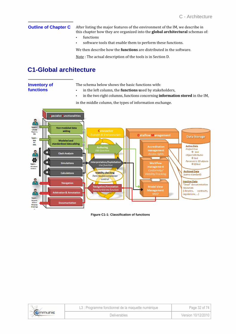
The schema below shows the basic functions with:
• in the left column, the functions used by stakeholders,
• in the two right columns, functions concerning information stored in the IM,
in the middle column, the types of information exchange.
Figure C1-1: Classification of functions

C - Architecture
L3 : Programme fonctionnel de la maquette numérique Page 33 of 74
Deliverables Version 10/12/2010
C1-Global architecture (Continued)
Simplified global architectur al schema
We describe below how we have organized these functions.
An environment consisting of large
areas
The following schema shows the simplified architecture of the Collaborative IM Environment (EIMC).
Figure C1-2: Perimeter of the global model
Perimeters These schemas are constructed on the definition of organized perimeters:
• "Environment of the COMMUNIC IM" (EIMC): perimeter of the overall model.
• "Disciplines": Designs of different disciplines.
• The "IM" or "Collaborative Exchange Platform (CEP): center of the model with two sub-schemes: - "Management" to manage information, - "Synthesis" to globalize the analysis and manage the project,
• "Exchange platform" which provides communication between the perimeters of the IM and the disciplines.
This structure will be described in more detail in Chapter C.

C - Architecture
L3 : Programme fonctionnel de la maquette numérique Page 34 of 74
Deliverables Version 10/12/2010
C1-Global architecture (Continued)
Representati on chart er
In all the diagrams in this chapter, we use the representation charter described below.
Perimeter
Disciplines Tools needed to design a project.
Exchange
platform Functions concerning the transfer of data, control, validity and consistency.
CEP
or IM
Perimeter of the collaborative exchange platform , also known as the IM.
Management
of CEP
Tools forming the heart of management of the IM: Collaborative Exchange Platform.
Summary of CEP
Tools needed for technical management of the project (synthesis, arbitration, etc.).
Types of features
Authoring
and direct
inputs
Features forming part of the process of data integration in the IM, hosted by the CEP.
Computation
and
simulation
Analysis and computational tools that take data from the central database for use by simulations and calculations controlled and operated by an expert who uses his expertise in this area.
Editing and
visualization
Features and processes for using data in technical documentation and publishing: export of such data in a format that does not allow their return, following a change, without remodeling (e.g., annotation of exported plans).
Pictograms
Human
intervention
Fundamental human intervention in the value creation process .
Engineering
work
Engineering work specific to one or more disciplines.

C - Architecture
L3 : Programme fonctionnel de la maquette numérique Page 35 of 74
Deliverables Version 10/12/2010
C1-Global architecture (Continued)
Detailed global architectural schema
Major functions of the "disciplines"
and "CEP" perimeters
The two "disciplines" and "CEP" perimeters cover basic features that can be summarized in the architectural schema of functions below.
Figure C1-3: Detailed diagram of the features of EI MC4
Translation into a global
software architectural
schema
Figure C1-4: Detailed software architecture schema of the EIMC
4 This schema is based largely on the work and conclusions of the INPRO European research project.

C - Architecture
L3 : Programme fonctionnel de la maquette numérique Page 36 of 74
Deliverables Version 10/12/2010
C1-Global architecture (Continued)
Operating cycle of software components
Figure C1-5: Operating cycle of software components
Comments on the cycle
In this example, the lifecycle of project data between different software packages follows these steps:
Step Action
1 Customer specifications and deliverable data are ordered and classified n the project environment.
2 Data, catalogs and modeling charter (default model) hosted by the IM, are extracted.
3 A geometric response to needs expressed by the client is modeled.
4 This model is housed in the platform.
5 The design is complemented by tests, calculations or simulations.
6 The results of simulations and calculations are documented.
7 Everything is hosted and managed in the IM.
8 Navigation in the IM allows the proposals to be visualized.
9 Tests of consistency, integration and synthesis are performed and analyzed.
10 Design choices may give rise to arbitration.
11 The chosen design is stored in the IM to be seen and used by other stakeholders.
C - Architecture
L3 : Programme fonctionnel de la maquette numérique Page 37 of 74
Deliverables Version 10/12/2010
C2 - Distribution of features
Distribution of features by perimeter
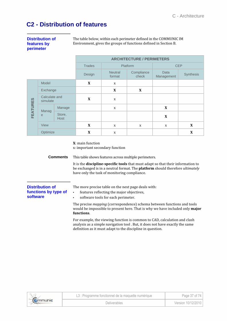
The table below, within each perimeter defined in the COMMUNIC IM Environment, gives the groups of functions defined in Section B.
ARCHITECTURE / PERIMETERS
Trades Platform CEP
Design Neutral format
Compliance check
Data Management Synthesis
FE
AT
UR
ES
Model X x
Exchange X X
Calculate and simulate X x
Manage
Manage x X
Store, Host X
View X x x x X
Optimize X x X
X: main function x: important secondary function
Comments This table shows features across multiple perimeters.
It is the discipline-specific tools that must adapt so that their information to be exchanged is in a neutral format. The platform should therefore ultimately have only the task of monitoring compliance.
Distribution of functions by type of software
The more precise table on the next page deals with:
• features reflecting the major objectives,
• software tools for each perimeter.
The precise mapping (correspondence) schema between functions and tools would be impossible to present here. That is why we have included only major
functions.
For example, the viewing function is common to CAD, calculation and clash analysis as a simple navigation tool . But, it does not have exactly the same definition as it must adapt to the discipline in question.

C - Architecture
L3 : Programme fonctionnel de la maquette numérique Page 38 of 74
Deliverables Version 10/12/2010
C2 - Distribution of features (Continued) Distribution of functions by type of software (Continued)
Architecture Discipline Platform CEP
Functions
TOOLS
Allo
tmen
t o
f spe
cific
atio
ns /
mod
elin
g of
raw
dat
a
Mod
eler
s
Sim
ulat
ion
tool
s, c
ompu
ters
, dis
cipl
ine-
spec
ific
brow
sers
G
raph
ic d
ocum
enta
tion
edito
r
Cal
cula
tion
and
disc
iplin
e-sp
ecifi
c vi
ew e
dito
r
Use
of a
neu
tral
exc
hang
e fo
rmat
Mon
itorin
g of
dat
a ex
chan
ge c
ompl
ianc
e
Mon
itorin
g th
e co
mpl
eten
ess
of d
ata
exch
ange
Mon
itorin
g of
com
plia
nce
in th
e ne
utra
l dat
a m
odel
Hos
ting
of o
rder
ed d
ata
Per
mis
sion
s m
anag
emen
t too
l
Vie
wpo
int m
anag
emen
t too
l
Wor
kflo
w to
ol
Bro
wse
r
Rul
e ch
ecke
r
Cla
sh a
naly
zer
Arb
itrat
ion
and
anno
tatio
n m
anag
emen
t too
l
Features
Shape
Addition of raw data
X x
Manual modeling
X x
Addition of modeled data
X X x
Exchange
Platform for import of data
to share X X X X x x x
Platform for partial import /
export of the shared data
(interpretation)
X X X X x x x
Read / publishing
export platform X X X X x x x
Calculate and simulate
Simulation X x x x Calculation X x x x Analysis of
clashes x X X
Manage
Rights by identity x X Flow monitoring
(Workflows) x X
Viewpoint rights (discipline)
x X
Store Host X
Order X
View Browse x x X x x x x X x x x
Annotate X Document X X x
Optimize Arbitrate x X
X: Main function x: Important secondary function

C - Architecture
L3 : Programme fonctionnel de la maquette numérique Page 39 of 74
Deliverables Version 10/12/2010
C3 - Assessment of the architecture
Key points When exchanges and their safety and quality constraints are globally taken into account, we realize that the key points of the COMMUNIC IM (EIMC) environment are:
• The Collaborative Exchange Platform (ECP). This is the crossroads of all work on the project. It is the place for managing and securing data.
• The transfer platform associated with a shared data model and neutral
exchange format. All data are imported or exported through this platform.
Comments on the perimeters
Conventional definition
The perimeters were defined conventionally for the COMMUNIC project. During implementation, they can be adapted.
For example, we established a specific perimeter for the platform rather than integrate it into the CEP. This is a choice we justify to call attention to the major functions it must perform to ensure the data model and neutral exchange format.
Similarly, standardization (data model and format) of information is a function of discipline-specific tools. This is so even though, for some time yet, standardizations can be realized by specific modules of the platform.
Duplicates allowed Some tools will be present in several perimeters.
This is for example the case of browsers (viewers). Indeed, it is essential that the CEP have an integrated browser that allows the synthesis functions. But this does not preclude that some disciplines have their own browsers for their own design work.

C - Architecture
L3 : Programme fonctionnel de la maquette numérique Page 40 of 74
Deliverables Version 10/12/2010
This page left blank intentionally
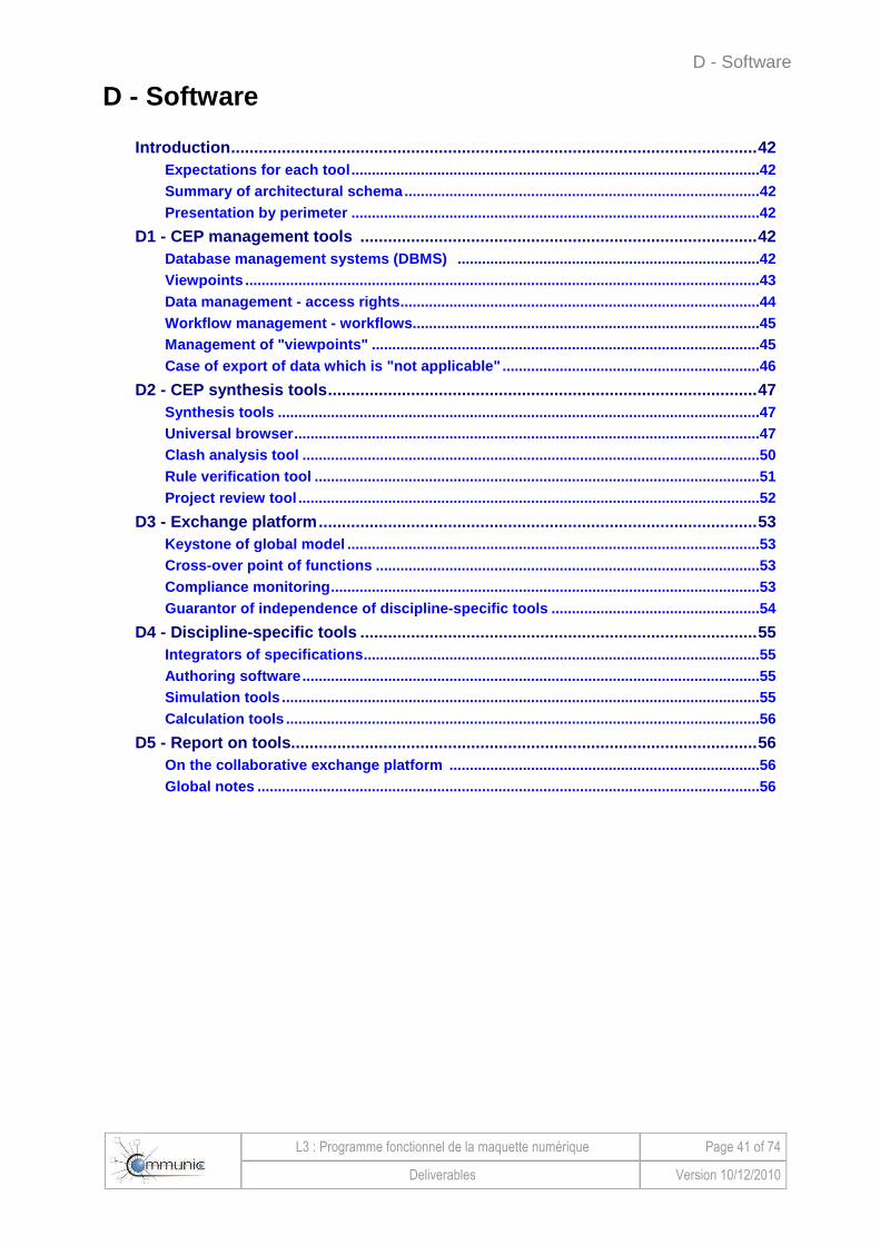
D - Software
L3 : Programme fonctionnel de la maquette numérique Page 41 of 74
Deliverables Version 10/12/2010
D - Software
Introduction ...................................... ............................................................................ 42 Expectations for each tool ........................ ............................................................................42 Summary of architectural schema ................... .................................................................... 42 Presentation by perimeter ......................... ...........................................................................42
D1 - CEP management tools ........................ .............................................................. 42 Database management systems (DBMS) .............. ............................................................42 Viewpoints ........................................ ......................................................................................43 Data management - access rights ................... .....................................................................44 Workflow management - workflows.................... .................................................................45 Management of "viewpoints" ........................ .......................................................................45 Case of export of data which is "not applicable" .. .............................................................46
D2 - CEP synthesis tools .......................... ................................................................... 47 Synthesis tools ................................... ...................................................................................47 Universal browser ................................. .................................................................................47 Clash analysis tool ............................... .................................................................................50 Rule verification tool ............................ .................................................................................51 Project review tool ............................... ..................................................................................52
D3 - Exchange platform ............................ ................................................................... 53 Keystone of global model .......................... ...........................................................................53 Cross-over point of functions ..................... .........................................................................53 Compliance monitoring ............................. ............................................................................53 Guarantor of independence of discipline-specific to ols ............................................... ....54
D4 - Discipline-specific tools .................... .................................................................. 55 Integrators of specifications ..................... ............................................................................55 Authoring software ................................ ................................................................................55 Simulation tools .................................. ...................................................................................55 Calculation tools ................................. ...................................................................................56
D5 - Report on tools .............................. ....................................................................... 56 On the collaborative exchange platform ........... .................................................................56 Global notes ...................................... .....................................................................................56
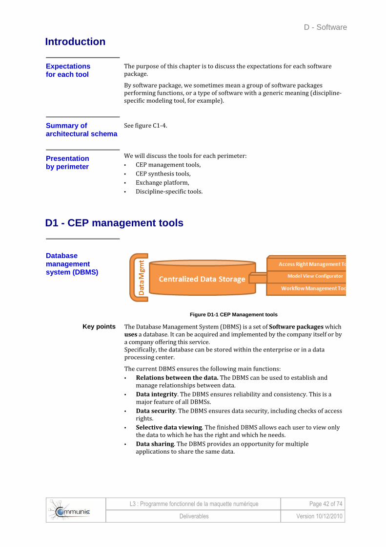
D - Software
L3 : Programme fonctionnel de la maquette numérique Page 42 of 74
Deliverables Version 10/12/2010
Introduction
Expectations for each tool
The purpose of this chapter is to discuss the expectations for each software package.
By software package, we sometimes mean a group of software packages performing functions, or a type of software with a generic meaning (discipline-specific modeling tool, for example).
Summary of architec tural schema
See figure C1-4.
Presentation by perimeter
We will discuss the tools for each perimeter:
• CEP management tools,
• CEP synthesis tools,
• Exchange platform,
• Discipline-specific tools.
D1 - CEP management tools
Database management system (DBMS)
Figure D1-1 CEP Management tools
Key points The Database Management System (DBMS) is a set of Software packages which uses a database. It can be acquired and implemented by the company itself or by a company offering this service. Specifically, the database can be stored within the enterprise or in a data processing center.
The current DBMS ensures the following main functions:
• Relations between the data. The DBMS can be used to establish and manage relationships between data.
• Data integrity. The DBMS ensures reliability and consistency. This is a major feature of all DBMSs.
• Data security. The DBMS ensures data security, including checks of access rights.
• Selective data viewing. The finished DBMS allows each user to view only the data to which he has the right and which he needs.
• Data sharing. The DBMS provides an opportunity for multiple applications to share the same data.

D - Software
L3 : Programme fonctionnel de la maquette numérique Page 43 of 74
Deliverables Version 10/12/2010
D1 - CEP management tools (Continued)
Points to note For the COMMUNIC project, the points which need attention have been identified.
Management of data
For us, data management means the management of:
• versions,
• alternatives,
• validation status of the information and associated circuitry,
• properties - private and public information, intellectual property, etc..
Currently, these functions can be found in Electronic Document Management (EDM) and Product Lifecycle Management (PLM) software. But these programs are designed to manage documents or files, not information carried by objects.
Sometimes we also find part of this functionality in authoring and project review software packages. For example, Revit integrates an alternative management function, and using the Bentley suite's Dynamic Review may grant a validation process to objects.
Unfortunately, the functions as they exist today are far from complete and perfect, particularly as regards data validation or maturity. Today's tools are most often more or less optimized EDMs, where we should be using a project PLM.
Traceability This maintains a history of how the data is handled. It fosters trust between partners and helps to keep track of the decisions taken.
This feature also appears in EDMs and PLMs for a database file. It must be transposed to the information attached to objects.
Management of "viewpoints"
The concept of "viewpoints" comes from the requirement to filter information to highlight that which relates to each stakeholder and not be drowned out by all the others. The DBMS must therefore manage the viewpoints of each stakeholder.
Currently, there is no concept of managing "viewpoints". In practice, it is handled by each software package, which takes all the data and converts those that can be used.
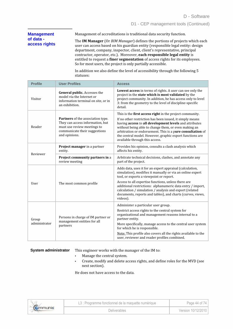
D - Software
L3 : Programme fonctionnel de la maquette numérique Page 44 of 74
Deliverables Version 10/12/2010
D1 - CEP management tools (Continued)
Management of d ata - access rights
Management of accreditations is traditional data security function.
The IM Manager (Or BIM Manager) defines the portions of projects which each user can access based on his guardian entity (responsible legal entity: design department, company, inspector, client, client's representative, principal contractor, operator, etc.). Moreover, each responsible legal entity is entitled to request a finer segmentation of access rights for its employees. So for most users, the project is only partially accessible.
In addition we also define the level of accessibility through the following 5 statuses:
Profile User Profiles Access
Visitor
General public. Accesses the model via the Internet or information terminal on site, or in an exhibition.
Lowest access in terms of rights. A user can see only the project in the state which is most validated by the project community. In addition, he has access only to level 3: from the geometry to the level of discipline-specific detail.
Reader
Partners of the association type. They can access information, but must use review meetings to communicate their suggestions and opinions.
This is the first access right in the project community.
If no other restriction has been issued, it simply means having access to all development levels and attributes without being able to change them, or even making an arbitration or endorsement. This is a pure consultation of the central model. However, graphic export functions are available through this access.
Reviewer
Project manager in a partner entity.
Provides his opinion, consults a clash analysis which affects his entity.
Project community partners in a review meeting
Arbitrate technical decisions, clashes, and annotate any part of the project.
User The most common profile
Adds data, uses it for an expert appraisal (calculation, simulation), modifies it manually or via an online expert tool, or exports a viewpoint or report.
Access to all expertise functions, unless there are additional restrictions: alphanumeric data entry / import, calculation / simulation / analysis and export (related documents, reports and tables), and charts (curves, views, videos).
Group administrator
Persons in charge of IM partner or management entities for all partners
Administer a particular user group.
Restrict access rights to the central system for organizational and management reasons internal to a partner entity.
More specifically, manage access to the central user system for which he is responsible.
Note: This profile also covers all the rights available to the user, reviewer and reader profiles combined.
System administrator
This engineer works with the manager of the IM to:
• Manage the central system.
• Create, modify and delete access rights, and define roles for the MVD (see next section).
He does not have access to the data.
D - Software
L3 : Programme fonctionnel de la maquette numérique Page 45 of 74
Deliverables Version 10/12/2010
D1 - CEP management tools (Continued)
Workflow management
Go from workflows of documents
managed by the EDM ....
The Workflows are used to qualify:
• the authenticity of the data,
• the level of relevance of the data.
Today, EDMs can both allow shared archiving of documents and associate "Workflow" information with the documents .
These systems are structured around an RDBMS that provides a link between a document and the features that in particular allow:
• identification of the document,
• the position in its life cycle (versioning)
• the status (validation),
• other documents as references,
• simultaneous use by several stakeholders.
... to information workflows managed by the digital model
These features are all integrated into the Collaborative Exchange Platform (IM), with two new aspects taken into account:
• The worfklow is no longer attached to a document (a drawing, report, file), but to information bound to the constructive object. In other words, information management tools must be integrated with the data model of the IM, which makes the attribute, associated with the object, the basic management unit.
• The conceptual model of the Workflow must itself take into account the complexity of the information validation cycle , including links with other information.
Management of "view points"
Navigating the IM according to criteria
The management of viewpoints is synonymous with "Model View Definition". It makes full use of the data model, profile management and Workflow we have described above.
This provides each user with a range of criteria for navigating the IM, and making requests which are relevant to him. These criteria are listed below.
Depending on the nature
of stakeholders
A first criterion is related to the profile of the stakeholder and his access rights.
For example, the public does not need to see the constructive details of a reinforcement if it is the insertion of the structure into agricultural structures that concerns them.
According to discipline
A second criterion is the discipline of the direct stakeholder.
For example, a stakeholder in the earthmoving business will wish to have all details of earthworks, and therefore see all child objects of the earthmoving object at Level 2. In contrast, children of objects in other disciplines at Level 2 do not interest him. It will be useful to be able to filter them out.

D - Software
L3 : Programme fonctionnel de la maquette numérique Page 46 of 74
Deliverables Version 10/12/2010
D1 - CEP management tools (Continued) Management of "viewpoints" (Continued)
According to the lifecycle or its
progress
A third criterion is of interest only to information relating to a phase of the lifecycle.
This is for example the case of a general presentation of the project while in the execution phase. It is also the case of selection of information according to its validation level or progress: What is approved information? What objects are being worked on today? etc.
By managing the characteristics of the
information
Hence, for this purpose, the tool should allow management of information depending on its individual characteristics.
The case of export of "non-object" data
These are graphic and alphanumeric export tools: maps, graphs, reports, calculations, lists, videos, etc.
Starting from the premise that all of the information is stored in the database, one case simply:
• retrieve the information necessary to prepare the report,
• format the report using a predefined template.
Today, there are software packages that can export "reports of clashes" and a list of all elements and their attributes in a table.
They are now an integral part of some simulation and calculation tools. They cannot be used to produce reports directly by transcribing a cross analysis between the weighted viewpoints of the various disciplines.
Tomorrow, automation
and image export
It will soon be possible to automate the preparation of technical notes, calculation notes, schedules, deliverables, etc. This is already possible today with some tools, but tomorrow it will be possible from a simple reading of the neutral format.
Similarly, it will be possible to export images and videos from the central IM for communication.
It can also be envisaged that this functionality will be integrated with the collaborative platform to save, for example, a graphic charter common to the project, or to be able to track what exports were made by whom and in what state of validation and maturity.

D - Software
L3 : Programme fonctionnel de la maquette numérique Page 47 of 74
Deliverables Version 10/12/2010
D2 - CEP synthesis tools
Synthesis tools
Figure D2-1: Tools of the CEP synthesis part
The universal browser
Based on the object data model defined by COMMUNIC, the browser is the tool that allows the IM to:
• consult stored data (3D geometry, attributes and links, trees);
• view objects at various levels by moving in the virtual structure in real time;
• create a location-based link between information and the objects that carry it .
The browser is the universal tool of the IM for accessing the data. In some cases, there may be dedicated browsers specific to particular issues.
Today ... In the software packages currently available, we find many products with which to display certain data formats.
Many are distributed free of charge. For example:
• Revit Viewer (. rvt)
• Bentley View (. dgn)
• SOLIBRA Model Viewer (.ifc and .smc)
• Nemetschek IFC Viewer (.ifc)
• DDSViewer (. ifc).
Figure D2-2: Model of earthmoving of the experiment al area in the SOLIBRI viewer

D - Software
L3 : Programme fonctionnel de la maquette numérique Page 48 of 74
Deliverables Version 10/12/2010
D2 - CEP synthesis tools (Continued) The universal browser (Continued)
... and tomorrow In COMMUNIC, we propose to integrate a basic browser in the collaborative exchange platform. The browser will be able to provide the following functions:
Access rights The browser uses the access rights management module , so the user has access only to data that he has the right to view and edit.
Visualization of discipline-specific
analysis results
The specialized designs of the disciplines will result in calculations, analyses, simulations and even visualizations.
When the designer decides to share the results with other stakeholders, he will place them in the IM. The browser will then display them. In particular, it will be possible to visualize them by superposing numerical results on the geometric model.
To illustrate this feature, we will take the case of acoustic studies with visualization of sound impact on objects of the IM.
Checking software can do the same kind of presentation for:
• structural analysis,
• climate analysis (heating, air conditioning, ventilation)
• 4D (3D + Schedule)
• 5D (4D + Cost)
• etc.
The figure below shows one possible display of sound impact on a project area.
Figure D2-3: Result of an acoustic analysis

D - Software
L3 : Programme fonctionnel de la maquette numérique Page 49 of 74
Deliverables Version 10/12/2010
D2 - CEP synthesis tools (Continued) The universal browser (Continued)
Tree according to the viewpoint of the
user's discipline
This tree should be organized around the basic structure and hierarchy in different levels (related to increasing precision of design). The tree structure that we established in the COMMUNIC project during the experiment is shown by the partial view below.
Figure D2-4: Extract from the tree developed for ex perimental Task 4 of the COMMUNIC project

D - Software
L3 : Programme fonctionnel de la maquette numérique Page 50 of 74
Deliverables Version 10/12/2010
D2 - CEP synthesis tools synthesis tools (Continued)
The universal browser (Continued)
Query by the browser
The query can limit the data to be visualized. The user is not buried in an excessively large mass of information, and quickly finds the information he needs.
The query criteria proposed by COMMUNIC are.
� Geographical location
Many cases require loading only part of the project, defined by geographical location. In the case of a complex project, it is likely that an engineer will be in charge of only one project area. For example, an earthworks engineer may be studying the first 10km of road. He may not be directly interested in the road beyond that.
� Systems and disciplines
A system is a set of objects in close relationship with each other, all performing well defined functions. In the COMMUNIC project, we distinguished the
following systems: drainage network, tolls, signing, monitoring, landscaping, operation and service, etc.
A discipline is a human activity in which experts in the discipline, working on a set of objects, use their know-how to achieve a given objective. The disciplines that we have chosen are the geometry of the project, earthworks, planning, cost, pavements, traffic flow, land, environment and archeology.
To facilitate the work of each user, the ability to query by systems and by disciplines seems essential for proper utilization and performance of the IM.
� Links
Links are an important part of the IM. And it is not often possible to view them in graphical interfaces. However, to understand the relations between objects, we must find a way to make them stand out.
� General Attributes
In addition to the specific querying mentioned above, the data browser must allow a query on any attribute. This list is not exhaustive, as other query criteria will appear when the IM is used.
Clash analysis tool This tool is currently one of the few present and operational among the various software packages on the market. The current tools can effectively detect interference and collisions, more commonly known as "clashes."
There are 5 types of clashes.
Geometric The geometry type is trivial. These are geometric intersections commonly called "clashes", which correspond to the intersection of two volumes or the accidental inclusion of one in another.
Functional They:
• check the absence of collisions in kinematical studies of moving parts,
• control the existence of the volumes necessary for assembly or disassembly tools, or the volumes required to access narrow parts of structures or hard-to-reach parts.

D - Software
L3 : Programme fonctionnel de la maquette numérique Page 51 of 74
Deliverables Version 10/12/2010
D2 - CEP synthesis tools synthesis tools (Continued)
Clash analysis tool (Continued)
Parametric This concerns the management of tolerances between objects, such as the thickness of the cover concrete. By this means, it is possible to verify that no selected reinforcement is "too close to the surface of the concrete", to avoid errors leading to the well-known spalling damage.
Regulatory This involves checking compliance with design rules, e.g., regulation of the design of outdoor public spaces, such as a rest area, primarily for access by disabled persons This regulation is primarily focused on strictly geometrical issues of the shape of stairs, slopes and minimum dimensions of spaces, etc.
Specific This involves checking compliance with design rules that are not regulatory, but issued by the client or defined by the project community.
A rule checker for the last 3
The last 3 types of clashes are analyzed by the rule checking tool.
However, the information about the existence of clashes is not itself hosted in the IM. This allows it to be directly accessible through an authoring tool. These tools allow you to edit "clash reports" which can, in the technical development phases of certain projects, be as long as hundreds of pages. Indeed, the information output by these tools is currently not "sorted",
customized, managed or monitored.
Rule checking tool This is an extra layer on the clash analysis tool.
This involves automatically checking that the result is in accordance with regulations and with the client's performance requirements.
For example, if the model contains a rule on the maximum deflection of beams , the rule checking tool can continuously detect beams of which the sag exceeds l/250 (l being the length of the beam) for the SLS (serviceability limit state). Engineers are thus notified in real-time about the elements it is required to change.
Similarly, it is possible to verify the correct application of urban design rules or rules giving accessibility to persons with reduced mobility.
Figure D2-5: View of a tool (SOLIBRA ®) to verify c ompliance
of design rules

D - Software
L3 : Programme fonctionnel de la maquette numérique Page 52 of 74
Deliverables Version 10/12/2010
D2 - CEP synthesis tools synthesis tool (Continued)
Project review tool
Intervene in the information
workflow
The arbitration and annotation tool helps in :
• revising the project,
• decision making,
• external communication of the project team.
It can not add, delete or edit existing data (except the validation and revision
attributes).
Save the history In the design phase, a comparison of analyses based on two alternatives of the same object (the results of various simulations, geometries, costs, etc.) will allow the making of informed decisions.
In the study phase, we must resolve conflicts, make decisions and validate solutions.
During the "review gate" at the end of each phase, a number of important decisions must be accepted by all partners. It is particularly in this phase that the use of a specific browser should make it possible to view and identify inconsistencies and record decisions and approvals. The IM thus keeps track of everything that was done and decided to arrive at the final version of the project.
Dematerialize the reviews
It is preferable to integrate the tool with the collaborative exchange platform to:
• Help dematerialize project reviews .
• Substantially reduce travel by stakeholders expected to participate in review meetings. This allows everyone to stay home to draw up these coordination reviews. They are more numerous and more frequent than in a traditional process.
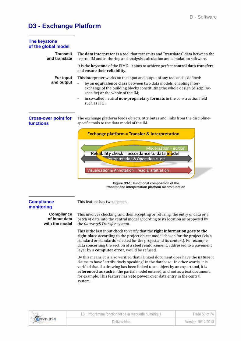
D - Software
L3 : Programme fonctionnel de la maquette numérique Page 53 of 74
Deliverables Version 10/12/2010
D3 - Exchange Platform
The keystone of the g lobal model
Transmit and translate
The data interpreter is a tool that transmits and "translates" data between the central IM and authoring and analysis, calculation and simulation software.
It is the keystone of the EIMC. It aims to achieve perfect control data transfers and ensure their reliability.
For input and output
This interpreter works on the input and output of any tool and is defined:
• by an equivalence class between two data models, enabling inter-exchange of the building blocks constituting the whole design (discipline-specific) or the whole of the IM;
• in so-called neutral non-proprietary formats in the construction field such as IFC .
Cros s-over point for functions
The exchange platform feeds objects, attributes and links from the discipline-specific tools to the data model of the IM.
Figure D3-1: Functional composition of the
transfer and interpretation platform macro function
Compliance monitoring
This feature has two aspects.
Compliance of input data
with the model
This involves checking, and then accepting or refusing, the entry of data or a batch of data into the central model according to its location as proposed by the Gateway&Transfer system.
This is the last input check to verify that the right information goes to the
right place according to the project object model chosen for the project (via a standard or standards selected for the project and its context). For example, data concerning the section of a steel reinforcement, addressed to a pavement layer by a computer error, would be refused.
By this means, it is also verified that a linked document does have the nature it claims to have "attributively speaking" in the database. In other words, it is verified that if a drawing has been linked to an object by an expert tool, it is referenced as such in the partial model entered, and not as a text document, for example. This feature has veto power over data entry in the central system.
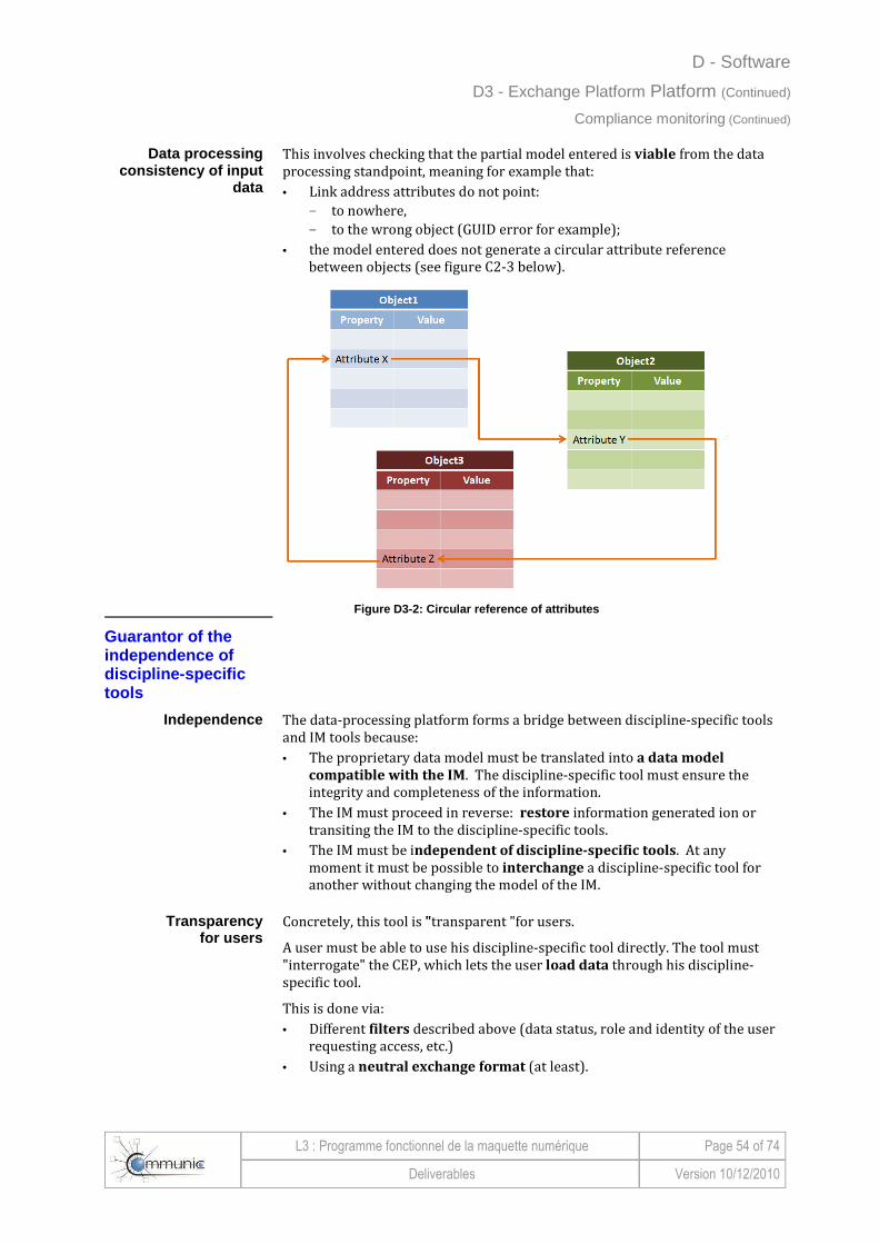
D - Software
L3 : Programme fonctionnel de la maquette numérique Page 54 of 74
Deliverables Version 10/12/2010
D3 - Exchange Platform Platform (Continued)
Compliance monitoring (Continued)
Data processing consistency of input
data
This involves checking that the partial model entered is viable from the data processing standpoint, meaning for example that:
• Link address attributes do not point: - to nowhere, - to the wrong object (GUID error for example);
• the model entered does not generate a circular attribute reference between objects (see figure C2-3 below).
Figure D3-2: Circular reference of attributes
Guarantor of the independence of discipline -specific tools
Independence The data-processing platform forms a bridge between discipline-specific tools and IM tools because:
• The proprietary data model must be translated into a data model
compatible with the IM. The discipline-specific tool must ensure the integrity and completeness of the information.
• The IM must proceed in reverse: restore information generated ion or transiting the IM to the discipline-specific tools.
• The IM must be independent of discipline-specific tools. At any moment it must be possible to interchange a discipline-specific tool for another without changing the model of the IM.
Transparency for users
Concretely, this tool is "transparent "for users.
A user must be able to use his discipline-specific tool directly. The tool must "interrogate" the CEP, which lets the user load data through his discipline-specific tool.
This is done via:
• Different filters described above (data status, role and identity of the user requesting access, etc.)
• Using a neutral exchange format (at least).
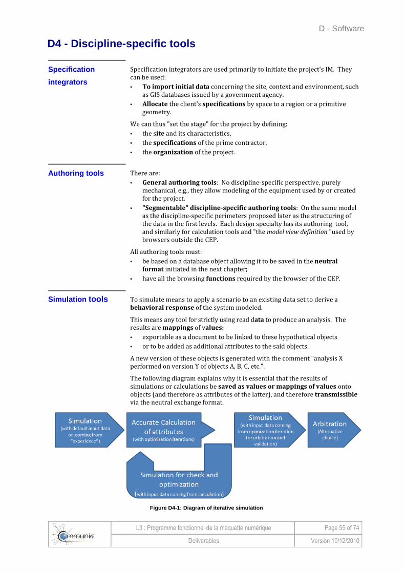
D - Software
L3 : Programme fonctionnel de la maquette numérique Page 55 of 74
Deliverables Version 10/12/2010
D4 - Discipline-specific tools
Specification
integrator s
Specification integrators are used primarily to initiate the project's IM. They can be used:
• To import initial data concerning the site, context and environment, such as GIS databases issued by a government agency.
• Allocate the client's specifications by space to a region or a primitive geometry.
We can thus "set the stage" for the project by defining:
• the site and its characteristics,
• the specifications of the prime contractor,
• the organization of the project.
Authoring tools There are:
• General authoring tools: No discipline-specific perspective, purely mechanical, e.g., they allow modeling of the equipment used by or created for the project.
• "Segmentable" discipline-specific authoring tools: On the same model as the discipline-specific perimeters proposed later as the structuring of the data in the first levels. Each design specialty has its authoring tool, and similarly for calculation tools and "the model view definition "used by browsers outside the CEP.
All authoring tools must:
• be based on a database object allowing it to be saved in the neutral
format initiated in the next chapter;
• have all the browsing functions required by the browser of the CEP.
Simulation tools To simulate means to apply a scenario to an existing data set to derive a behavioral response of the system modeled.
This means any tool for strictly using read data to produce an analysis. The results are mappings of values:
• exportable as a document to be linked to these hypothetical objects
• or to be added as additional attributes to the said objects.
A new version of these objects is generated with the comment "analysis X performed on version Y of objects A, B, C, etc.".
The following diagram explains why it is essential that the results of simulations or calculations be saved as values or mappings of values onto objects (and therefore as attributes of the latter), and therefore transmissible via the neutral exchange format.
Figure D4-1: Diagram of iterative simulation

D - Software
L3 : Programme fonctionnel de la maquette numérique Page 56 of 74
Deliverables Version 10/12/2010
D4 - Discipline-specific tools (Continued)
Calculation tools To calculate means to dimension the component elements of the system of parametric objects which constitute a multi-discipline IM.
We understand by this term, the use, the modification and the creation of objects via a technical analysis. For example, in a structural calculation of reinforced concrete, we:
1 Perform a simulation by taking the structure outlined and loading it.
2 Analyze the results to optimize them.
3 Complete this work by specifying the model that best meets the needs expressed by the simulation.
D5 - Report on tools
On the collaborative exchange platform
The minimum functions required by the CEP are:
• Hosting of data: - storage - management of exchanges, - access regulation by profiles, - management of data flows (Workflows).
• The exchange platform to the discipline-specific CAD, calculation and simulation and project review tools, ideally through a neutral and open format (such as IFC in the building field).
Addition of functions To these minimal functions are added the functions of:
• clash analysis,
• project review (navigation and arbitration of alternatives and clashes)
• check of geometric rules based on design standards.
These are the functional building blocks that must remain interchangeable
software building blocks.
Overall remarks
The aim of this part of the deliverable is not to define all the requirements that constitute a functional, "performance-oriented" specification of a future system.
However, we can allow ourselves to hope that the harmonization of publishers' developments will see the emergence of:
• an ecosystem of convergent tools,
• a standard for the data model.
This will connect the world of GIS (for linear infrastructure and networks) and the Civil Engineering BIM (for engineering structures and buildings) in an open XML coding if the source remains in the public domain.
E - Data model
L3 : Programme fonctionnel de la maquette numérique Page 57 of 74
Deliverables Version 10/12/2010
E - Data model
Introduction ...................................... ............................................................................ 58 The data model, the mainstay of the exchange standa rd ................................................ .58 An approach to basics, non-exhaustive ............. .................................................................58
E1 - General characteristics of data model ........ ........................................................ 59 Reference model ................................... .................................................................................59 Nesting of IM ..................................... .....................................................................................60
E2 - The COMMUNIC data model ...................... .......................................................... 61 Structuring in levels of physical objects ......... ....................................................................61 Information attached to physical objects .......... ..................................................................63 Characteristics of each piece of information ..... ................................................................63 Systems transversal to structuring in levels ...... ................................................................63

E - Data model
L3 : Programme fonctionnel de la maquette numérique Page 58 of 74
Deliverables Version 10/12/2010
Introduction
The data model, the mainstay of the exchange standard
The preceding chapters show, from the functions expected and the architectural schemas, that the COMMUNIC global model requires a standard for exchanging information. This standard comprises:
• a shared data model,
• a neutral exchange format.
Note: The standard-setting process (which will include defining a data model) is the subject of Chapter F below.
An approach to basics , non- exhaustive
In the functional program, we discuss the data model and indicate what we think it is essential to take into account in the data model to conform to the COMMUNIC global model.
This chapter does not attempt to describe a data model that is ready to be applied, so do not seek the completeness and consistency of a detailed data model here.
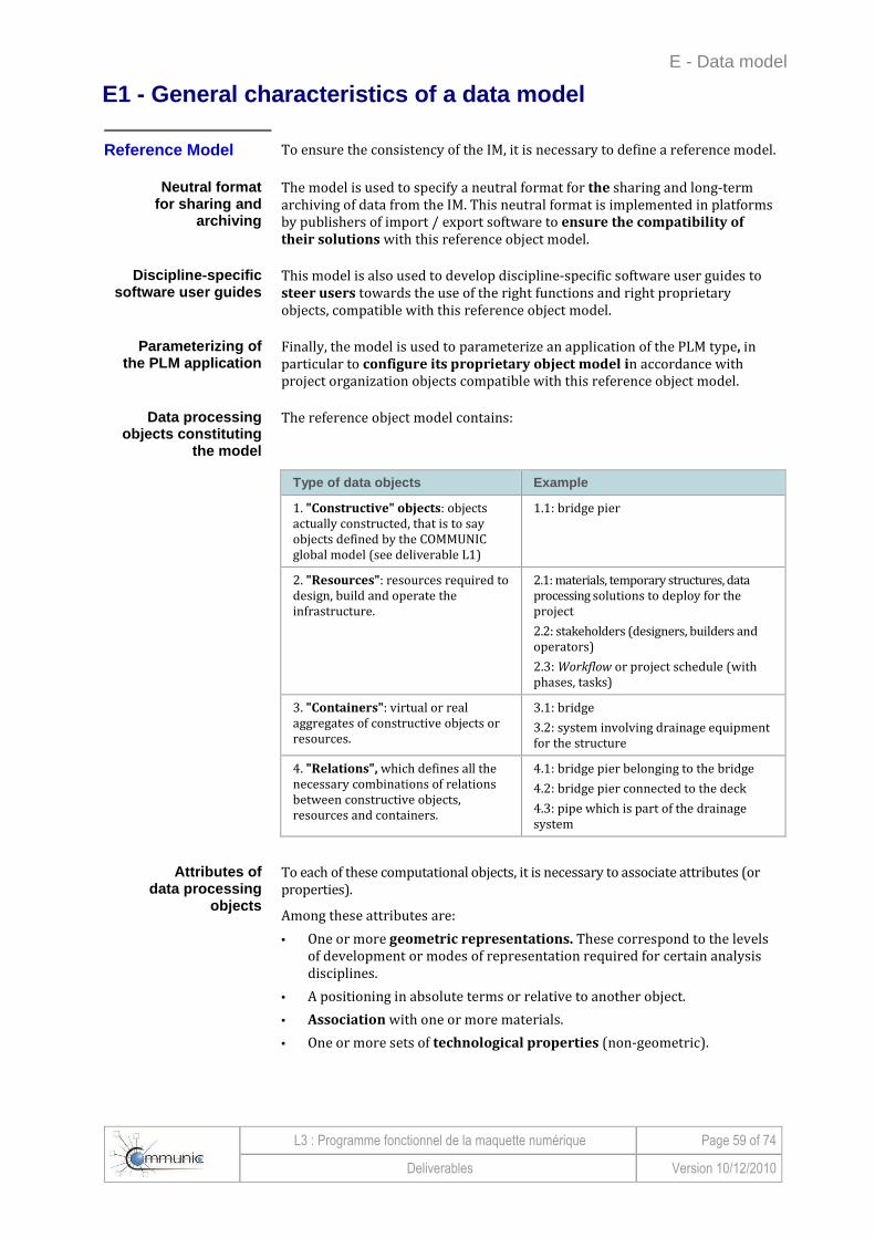
E - Data model
L3 : Programme fonctionnel de la maquette numérique Page 59 of 74
Deliverables Version 10/12/2010
E1 - General characteristics of a data model
Reference Model To ensure the consistency of the IM, it is necessary to define a reference model.
Neutral format for sharing and
archiving
The model is used to specify a neutral format for the sharing and long-term archiving of data from the IM. This neutral format is implemented in platforms by publishers of import / export software to ensure the compatibility of
their solutions with this reference object model.
Discipline-specific software user guides
This model is also used to develop discipline-specific software user guides to steer users towards the use of the right functions and right proprietary objects, compatible with this reference object model.
Parameterizing of the PLM application
Finally, the model is used to parameterize an application of the PLM type, in particular to configure its proprietary object model in accordance with project organization objects compatible with this reference object model.
Data processing objects constituting
the model
The reference object model contains:
Type of data objects Example
1. "Constructive" objects: objects actually constructed, that is to say objects defined by the COMMUNIC global model (see deliverable L1)
1.1: bridge pier
2. "Resources": resources required to design, build and operate the infrastructure.
2.1: materials, temporary structures, data processing solutions to deploy for the project
2.2: stakeholders (designers, builders and operators)
2.3: Workflow or project schedule (with phases, tasks)
3. "Containers": virtual or real aggregates of constructive objects or resources.
3.1: bridge
3.2: system involving drainage equipment for the structure
4. "Relations", which defines all the necessary combinations of relations between constructive objects, resources and containers.
4.1: bridge pier belonging to the bridge
4.2: bridge pier connected to the deck
4.3: pipe which is part of the drainage system
Attributes of data processing
objects
To each of these computational objects, it is necessary to associate attributes (or properties).
Among these attributes are:
• One or more geometric representations. These correspond to the levels of development or modes of representation required for certain analysis disciplines.
• A positioning in absolute terms or relative to another object.
• Association with one or more materials.
• One or more sets of technological properties (non-geometric).

E - Data model
L3 : Programme fonctionnel de la maquette numérique Page 60 of 74
Deliverables Version 10/12/2010
E1 - General characteristics of a data model (Continued)
Nestin g of the IM The volume and multidisciplinary character of the data in the IM inevitably pose the problem of how to store it and how to share it.
Models nested like Russian dolls
It is unlikely to be possible to store all the data of a model in a single file. We must therefore consider storing the data in network of files.
Each file, corresponding to a partial model, can be:
• a description of a constructive object or a container that can correspond to one lot of the project,
• a special discipline (structure, fluid networks, etc.)
• phase of the project (e.g., APS, APD, etc..)
• version of the project
• alternative form of the project.
Example of nesting A file nesting schema, or a CityGML file, can be used to describe the overall
project on a territorial scale. This CityGML file refers to external IFC files, which allow you to describe in detail any particular element of the construction project:
Figure E1-1: Example of links between partial model s
Links between models to be
managed by specific tools
This is known as nesting of models. It is managed by two types of tools:
• Synthesis tools, that allow us to verify the consistency of these sub-models and detect possible clashes.
• PLM type tools, which allow us to manage the entire lifecycle of the construction project by associating each sub-model with authors and reviewers, with planning elements, etc.

E - Data model
L3 : Programme fonctionnel de la maquette numérique Page 61 of 74
Deliverables Version 10/12/2010
E2 - The COMMUNIC data model
Structuring of physical objects in levels
The model must be based on "physical" objects, that is to say the future components of the structure to be built.
Objects: the elements that
structure the model
The term "object" is used here not in the sense of a computing object representing a characteristic, relation, rule, etc., but to refer to a part of the
structure that is geometrically defined and will actually be built.
The examples of items found in infrastructure illustrate the diversity of the
physical objects in terms of domain and level of detail. Examples of objects that are computing objects to be manipulated rather than physical objects are also given. They are usually items of information.
This assumption underlies the model database.
Examples of physical objects Examples of data objects
diversion view of a drainage system embankment body bridge pier tunnel reinforcement of bridge deck concrete
approval date of a record reference speed permissible stress of a material color of a railing axis of the infrastructure cost of a VMS
The structure to be built
is structured into levels
The visions we want to obtain of the structure, and the progressive character of the studies, lead us to organize the structure into levels containing increasingly detailed objects.
The data model must be designed with the following first 3 levels:
� Level 0 - the project This level is always reserved for the overall object of the project. So, physically, it is the entire structure to be built.
� Level 1 - functional structures This level corresponds to a breakdown of the project into functional objects. In fact, an infrastructure project is divided into parts usually called "structures", each of which performs a practical function.
Object of level 1 Function to be performed
Motorway Allow vehicles to travel on the motorway
RN138 Keep the RN 138 open to traffic
Power line Transmit electric power across the project
Stream Let the water of the stream flow
Subgrade Support the project
� Level 2 – discipline-specific structures This level corresponds to a breakdown of each functional structure into discipline-specific objects (or fields) that must be mobilized to build it.
Object of level 2 Work done by
Engineering structures
Companies specializing in engineering structures
Earthworks Excavation contractors
Drainage Drainage contractors
Pavements Pavement contractors
The most detailed levels are defined on a case-by-case basis taking account of the specificities of the project and fields concerned.
One reason for deciding how to break these levels down is that projects are generally estimated at the intersection of levels 1 and 2 (types of structures / nature of work).

E - Data model
L3 : Programme fonctionnel de la maquette numérique Page 62 of 74
Deliverables Version 10/12/2010
E2 - The COMMUNIC data model data model Continued) Structuring of physical objects in levels (Continued)
Example of structuring
The diagrams below illustrate the logic of this structuring into objects by level, and the transversal character of the systems.
Figure E2-1: Example of structuring of a project in to objects by levels
Transposition of the IFCs
There is an analysis of the transposition of the building, bridge and infrastructure IFCs in Appendix 3.

E - Data model
L3 : Programme fonctionnel de la maquette numérique Page 63 of 74
Deliverables Version 10/12/2010
E2 - The COMMUNIC data model (Continued)
Information attached to physical objects
The data model must organize information related to objects.
Any information relating to the
project is traceable to an object
Given the above structuring into objects by level, it is possible to trace any information about a project to an object.
The nature of the information lets us select an object to which the information is relevant. It is usually only the object at the highest level that concerns us.
Three categories of information attached
to an object
The quantity of information that can be attached to an object is large. We must therefore organize its storage. We have decided to retain three categories of information:
• information that allows geometric definition,
• information that characterizes the object - its attributes,
• information about relations with the attributes of other objects - links.
Geometric definition This is all the information that defines:
• the volume of the object, its external or internal surfaces,
• its positioning in space.
Attributes This is all the information that is specific to the object and characterizes it. We can cite for example: the type of material, weight, cost, completion date.
Links These are constraints or rules to follow between the attributes of the object and the attributes of other objects.
These links could include for example:
• geometry, with a surface that must be in contact with a surface of another object,
• scheduling, with one object to be implemented after another,
• a cost, which is the sum of the costs of "child objects"、
• a load related to the weight of another object,
• a co-visibility.
Characteristics of each item of information
The IM must manage information. So all information must be precisely defined, for example:
• the owner,
• public or private,
• confidentiality,
• status,
• date of coming into validity.
Systems that cut across the structuring in to levels
The global COMMUNIC model has identified transversal systems that must be
managed as well as levels in the structuring of objects.
These systems must be defined case-by-case for each project, but the data model must be designed to be able to manage them.
Links are reserved to identify:
• the systems to which the object belongs,
• the attributes which are useful in the management of these systems.

E - Data model
L3 : Programme fonctionnel de la maquette numérique Page 64 of 74
Deliverables Version 10/12/2010
This page left blank intentionally
F - Roadmap to a COMMUNIC exchange standard
L3 : Programme fonctionnel de la maquette numérique Page 65 of 74
Deliverables Version 10/12/2010
F - Roadmap to a COMMUNIC exchange standard
Introduction ...................................... ............................................................................ 66
Objective ......................................... ........................................................................................66
Contents .......................................... .......................................................................................66
Roadmap for a COMMUNIC exchange standard .......... ......................................................67
F1 - Use of existing standards .................... ................................................................ 68
"Mapping "of standards ..................................... ....................................................................68
Usability ......................................... .........................................................................................68
Examples of use
F2 - Toolkit ...................................... ............................................................................. 73
Common software components ........................ ...................................................................73
Standard Development Kit (SDK) .................... .....................................................................73
Reference visualization tools
Tests and testing procedures ...................... .........................................................................74

F - Roadmap to a COMMUNIC exchange standard
L3 : Programme fonctionnel de la maquette numérique Page 66 of 74
Deliverables Version 10/12/2010
Introduction
Objective
Standardize the data model
This chapter describes how to standardize the COMMUNIC neutral data
model as presented in Chapter E.
Choice of standard of IFC type
Given:
• the level of detail expected by COMMUNIC partners (engineering firms and construction companies)
• the maturity of the IFC format,
• work already completed for engineering structures (the IFC-Bridge project)
it is an extension of the IFC standard which is referred to for the standardization of the COMMUNIC data model.
Contents The following list describes the modules in Chapter F:
Module Contents
F1 - The approach to developing a standard
Procedure to define an extension of the IFC standard.
F2 - Existing standards
Hints and sources of inspiration, drawn from existing standards (IFC, CityGML, LandXML, etc.) to complete this process of standardizing the COMMUNIC model.
F3 - Development tools
Some software components developed to support the inclusion of the new standard by software publishers.

F - Roadmap to a COMMUNIC exchange standard
L3 : Programme fonctionnel de la maquette numérique Page 67 of 74
Deliverables Version 10/12/2010
Introduction (Continued)
Roadmap for a COMMUNIC exchange standard
If we follow the concept of the BuildingSMART Aquarium, the process of developing an IFC Infrastructure Standard is normally as follows. It should be noted that this approach is obviously iterative, with gradual introduction of new processes and discipline-specific views.
Step Approach Description
1 Medi@construct request
Formulation of the request for a new IFC project to its BuildingSMART chapter, namely the Medi@construct association for France.
2 Internationalization
Search for at least two other international BuildingSMART chapters ready to support the project. For infrastructure, this should not pose any major problem, in view of the fact that the German, Japanese and Scandinavian chapters have already expressed interest.
3 Organization
Assembling the project with the appointment of a "Project Leader "and a "Technical Leader" . For this pair, a Franco-German tandem is most likely.
At this stage we should also identify the BuildingSMART experts, a priori members of the group (MSGModeling Support Group), who will accompany us.
4 Associating publishers
The Aquarium concept combines the authoring and implementation phases. It would certainly be beneficial to involve a few software companies, which validate the standard developed by implementing it.
5 Formalization of the process
Authoring then begins with the formalization of the process, using the IDM formalism (Information Delivery Manual - http://www.iai.no/idm/), starting over again from the work of the global COMMUNIC model and the potential contributions of other chapters.
This involves specifying, in the IDM formalism, the processes described in the global COMMUNIC model (deliverable L1).
6 Translation into discipline-specific views
From these IDM formalisms, we extract discipline-specific views which are formalized using the MVD mechanism (Model View Definition - http://www.blis-project.org/IAI-MVD/ ). These are used to precisely specify the requirements in terms of mapping to the existing IFCs or the creation of new entities.
This involves specifying the COMMUNIC data model objects, as outlined in Chapter E.
7 "Mapping"
Mapping and IFC extension work is then carried out by MSG experts who produce an EXPRESS schema for IFC-Infrastructure. This schema should be a combination and an extension of the IFC 2X4 and IFC-Bridge schemas.
The next module in this chapter shows initial mapping paths.
8 Development toolbox
The EXPRESS product schema is then used to produce SDK for read / write of IFC-Infrastructure instances.
Example: use of the Expressik automatic generator to automatically produce SDK from the EXPRESS schema.
Examples of SDK are described in the next module.
9
Definition of tests A set of IFC test files consistent with the IFC-Infrastructure schema is produced, more or less manually. It is used to test the interfaces.
Test procedures Automatic test procedures and a reference viewing tool may also be developed (e.g., extension of the CSTB's eveBIM viewer).
10 Implementation by publishers
Software vendors are now implementing a new standard based on previously developed components.
11 Industrial validation
An industrial validation phase is being conducted by users of the interfaced
software tools in the various disciplines.
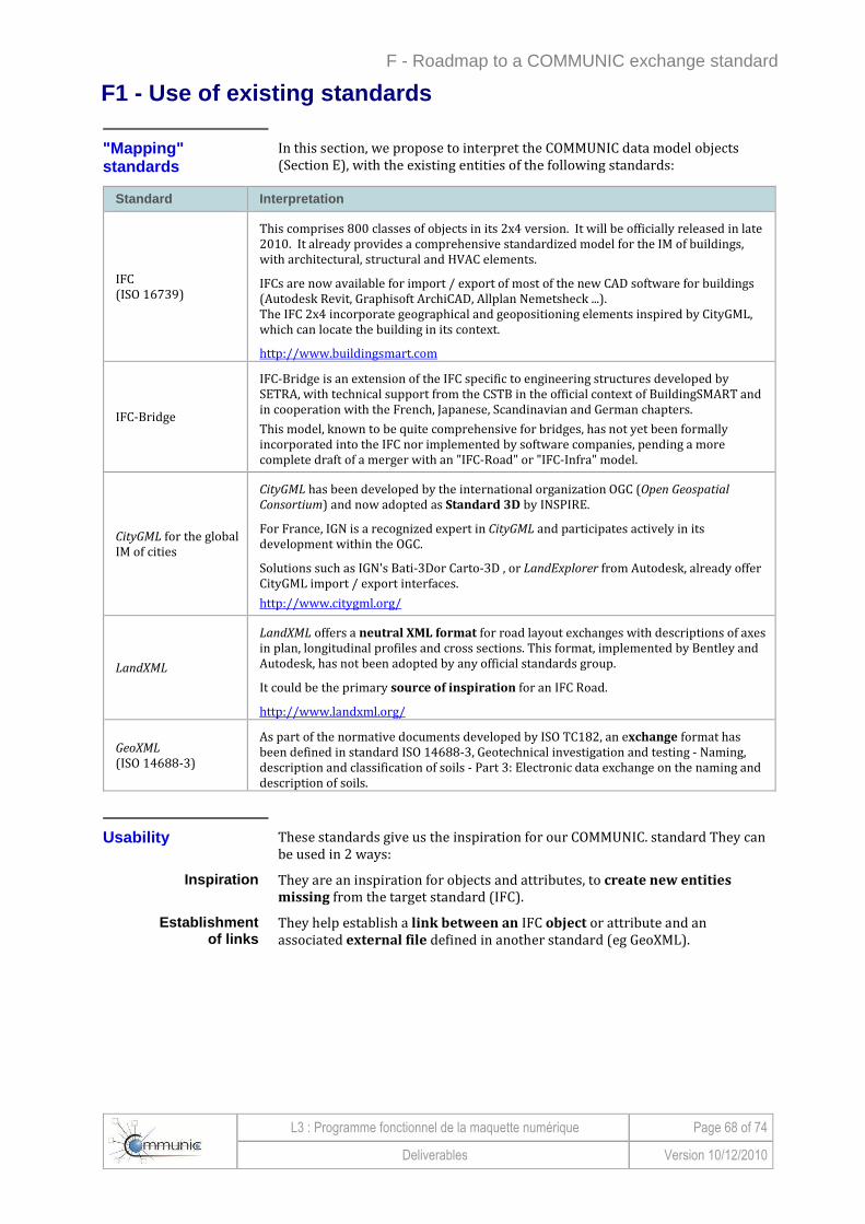
F - Roadmap to a COMMUNIC exchange standard
L3 : Programme fonctionnel de la maquette numérique Page 68 of 74
Deliverables Version 10/12/2010
F1 - Use of existing standards
"Mapping " standards
In this section, we propose to interpret the COMMUNIC data model objects (Section E), with the existing entities of the following standards:
Standard Interpretation
IFC (ISO 16739)
This comprises 800 classes of objects in its 2x4 version. It will be officially released in late 2010. It already provides a comprehensive standardized model for the IM of buildings, with architectural, structural and HVAC elements.
IFCs are now available for import / export of most of the new CAD software for buildings (Autodesk Revit, Graphisoft ArchiCAD, Allplan Nemetsheck ...). The IFC 2x4 incorporate geographical and geopositioning elements inspired by CityGML, which can locate the building in its context.
http://www.buildingsmart.com
IFC-Bridge
IFC-Bridge is an extension of the IFC specific to engineering structures developed by SETRA, with technical support from the CSTB in the official context of BuildingSMART and in cooperation with the French, Japanese, Scandinavian and German chapters.
This model, known to be quite comprehensive for bridges, has not yet been formally incorporated into the IFC nor implemented by software companies, pending a more complete draft of a merger with an "IFC-Road" or "IFC-Infra" model.
CityGML for the global IM of cities
CityGML has been developed by the international organization OGC (Open Geospatial
Consortium) and now adopted as Standard 3D by INSPIRE.
For France, IGN is a recognized expert in CityGML and participates actively in its development within the OGC.
Solutions such as IGN's Bati-3Dor Carto-3D , or LandExplorer from Autodesk, already offer CityGML import / export interfaces.
http://www.citygml.org/
LandXML
LandXML offers a neutral XML format for road layout exchanges with descriptions of axes in plan, longitudinal profiles and cross sections. This format, implemented by Bentley and Autodesk, has not been adopted by any official standards group.
It could be the primary source of inspiration for an IFC Road.
http://www.landxml.org/
GeoXML (ISO 14688-3)
As part of the normative documents developed by ISO TC182, an exchange format has been defined in standard ISO 14688-3, Geotechnical investigation and testing - Naming, description and classification of soils - Part 3: Electronic data exchange on the naming and description of soils.
Usability These standards give us the inspiration for our COMMUNIC. standard They can be used in 2 ways:
Inspiration They are an inspiration for objects and attributes, to create new entities
missing from the target standard (IFC).
Establishment of links
They help establish a link between an IFC object or attribute and an associated external file defined in another standard (eg GeoXML).
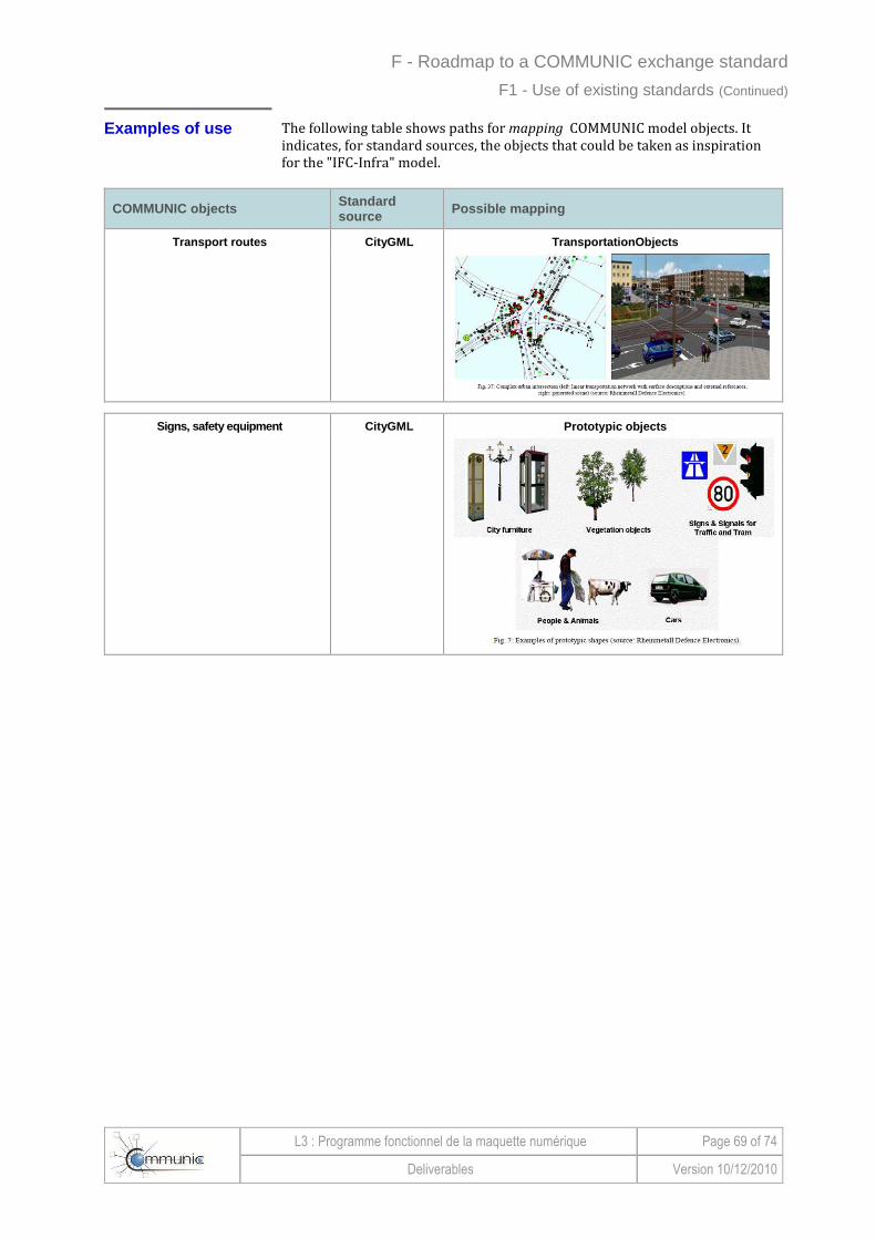
F - Roadmap to a COMMUNIC exchange standard
L3 : Programme fonctionnel de la maquette numérique Page 69 of 74
Deliverables Version 10/12/2010
F1 - Use of existing standards (Continued)
Examples of use The following table shows paths for mapping COMMUNIC model objects. It indicates, for standard sources, the objects that could be taken as inspiration for the "IFC-Infra" model.
COMMUNIC objects Standard source Possible mapping
Transport routes CityGML TransportationObjects
Signs, safety equipment CityGML Prototypic objects

F - Roadmap to a COMMUNIC exchange standard
L3 : Programme fonctionnel de la maquette numérique Page 70 of 74
Deliverables Version 10/12/2010
F1 - Use of existing standards (Continued) Examples of use (Continued)
COMMUNIC object Standard source Possible mapping
Profile of the road or engineering structure
LandXML
IFC-Bridge IfcBridgeSectionSpine
IfcBridgeClothoid
IfcBridgeProfileDef

F - Roadmap to a COMMUNIC exchange standard
L3 : Programme fonctionnel de la maquette numérique Page 71 of 74
Deliverables Version 10/12/2010
F1 - Use of existing standards (Continued) Examples of use (Continued)
COMMUNIC object Standard source Possible mapping
Fluid networks IFC 2X4 IfcPlumbingFireProtectionDom ain
IfcHvacDomain
IfcElectricalDomain
Bridges IFC-Bridge IfcBridge, IfcBridgeStructureEle ment, IfcBridgeSegment

F - Roadmap to a COMMUNIC exchange standard
L3 : Programme fonctionnel de la maquette numérique Page 72 of 74
Deliverables Version 10/12/2010
F1 - Use of existing standards (Continued) Examples of use (Continued)
COMMUNIC object Standard source Mapping possible
Industrial Buildings IFC 2X4 TBA
Hydraulic Structures TBD TBA
Earthworks CityGML Digital Terrain Model (DTM) ���� to complete
Site / context IFC 2X4 IfcSite
CityGML LanduUse
Geotechnical GeoXML TBA

F - Roadmap to a COMMUNIC exchange standard
L3 : Programme fonctionnel de la maquette numérique Page 73 of 74
Deliverables Version 10/12/2010
F2 - Toolkit
Common software components
To implement standards like IFC and CityGML that are very rich and therefore complex, software publishers must rely on common software components to facilitate their implementation.
The toolkit includes:
• standard development kit (SDK)
• reference visualization tools
• tests and testing procedures.
Standard Development Kit (SDK)
Programming libraries
Libraries (SDK / API) in various languages (C + +, Java, etc.) are integrated into the discipline-specific software (CAD, analysis, etc..) to ensure connection (read / write) with data formats associated with standards.
For IFCs Under the eXpert project (ICT-SME 2010), CSTB has developed such a library in C + + for IFC.
This IFC-SDK is now already operational with a coverage of 100% of the IFC 2X3 standard, currently implemented by most building software publishers (Autodesk, Nemetscheck, Graphisoft, etc.).
It is available in Open Source on the free software site from the European Community OSOR: https://www.osor.eu/projects/ifc-sdk.
Figure F2-1: Example of programming library
The above example shows the open source programming library IFC-SDK, the result of cooperation of CSTB with the European Space Agency and the
University of Manchester.
For CityGML Under the ANR TerraMagna, CSTB has developed a prototype SDK for CityGML.
For its own needs as part of its Bati-3D and Carto-3D offerings, IGN has also developed this kind of component to read/write the CityGML format.

F - Roadmap to a COMMUNIC exchange standard
L3 : Programme fonctionnel de la maquette numérique Page 74 of 74
Deliverables Version 10/12/2010
F2 - Toolkit (Continued)
Reference visualization tools
Visualization tools for reference:
• facilitate understanding and navigation in data standards;
• are involved in validation interfaces for discipline-specific software.
For buildings At the building and IFC level, CSTB has developed a visualization tool, eveBIM. It can:
• upload IFC files
• visualize them,
• explore them,
• possibly enrich them for coupling with simulation tools.
This tool is nearly operational. It has entered a beta testing phase with buildingSMART representatives and some industry testers.
For the urban environment
On a territorial and city-wide scale, CSTB has developed the eVEGA software package. It has the same functions as for buildings.
Under TerraMagna, a CityGML format file import prototype has been developed in eVEGA.
Tests and test procedures
There are suites of test cases and automated test procedures. They facilitate validation of software interfaces, and thus prepare them for their certifications with buildingSMART.
An existing service to be improved
BuildingSMART already offers such services, particularly through its new GTDS server.
However, all software publishers and end users of software, a priori certified, believe that these services must be substantially improved. See: http://www.iai.hm.edu/


