48
INSTRUCTION MANUAL iC- r8500 COMMUNICATIONS RECEIVER
INSTRUCTION MANUAL
iC-r8500COMMUNICATIONS RECEIVER
The IC-R8500 complies with essential require-ments of the 89/336/EEC directive forElectromagnetic Compatibility. This compliance is
based on conformity with the ETSI specification prETS300684 (EMC product standard for Commercially AvailableAmateur Radio Equipment).
UNPACKING
PRECAUTIONS
IMPORTANT
READ THIS INSTRUCTION MANUALCAREFULLY before attempting to operate thereceiver.
SAVE THIS INSTRUCTION MANUAL. Thisinstruction manual contains important safety and oper-ating instructions for the IC-R8500.
EXPLICIT DEFINITIONS
RINDOOR USE ONLY! NEVER expose theIC-R8500 or AC adapter to rain, snow or any liquids.
RNEVER connect the receiver to an AC outletdirectly. This may pose a fire hazard or result in anelectric shock. Always use the supplied AC adapter orconnect to a 13.8 V DC power source.
RNEVER connect to an AC outlet that exceeds thesuggested voltage for each AC adapter version. Thiscould cause a fire or ruin the AC adapter and/orreceiver.
RNEVER use non-rated fuses. Non-rated fusescould cause a fire or ruin the receiver.
NEVER let metal, wire or other objects touch anyinternal part or connectors on the rear panel of the
receiver. This will cause electric shock.
AVOID using or placing the receiver in areas with tem-peratures below –10°C (+14°F) or above +50°C(+122°F).
AVOID placing the receiver in excessively dusty envi-ronments or in direct sunlight.
AVOID placing the receiver against walls or puttinganything on top of the receiver. This will obstruct heatdissipation.
RESPECT other people’s privacy. Information over-heard but not intended for you cannot lawfully be usedin any way.
i
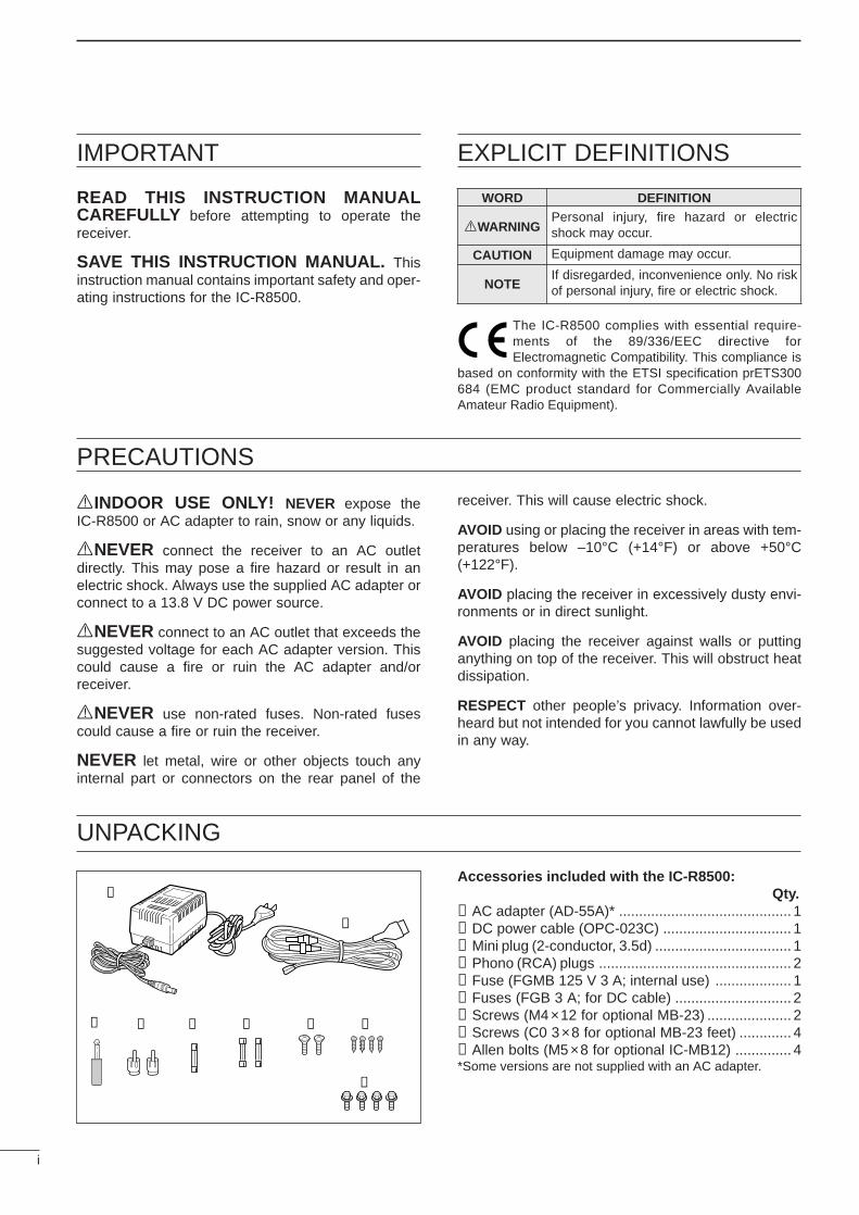
Accessories included with the IC-R8500:Qty.
➀AC adapter (AD-55A)* ........................................... 1➁DC power cable (OPC-023C) ................................ 1➂Mini plug (2-conductor, 3.5d) .................................. 1➃Phono (RCA) plugs ................................................ 2➄Fuse (FGMB 125 V 3 A; internal use) ................... 1➅Fuses (FGB 3 A; for DC cable) ............................. 2➆Screws (M4×12 for optional MB-23) ..................... 2➇Screws (C0 3×8 for optional MB-23 feet) ............. 4➈Allen bolts (M5×8 for optional IC-MB12) .............. 4*Some versions are not supplied with an AC adapter.
➀
➁
➂ ➃ ➄ ➅ ➆ ➇
➈
WORD DEFINITION
RWARNINGPersonal injury, fire hazard or electricshock may occur.
CAUTION Equipment damage may occur.
NOTEIf disregarded, inconvenience only. No riskof personal injury, fire or electric shock.
TABLE OF CONTENTS
IMPORTANT ............................................................. iEXPLICIT DEFINITIONS .......................................... iPRECAUTIONS ........................................................ iUNPACKING ............................................................. iTABLE OF CONTENTS ............................................ ii
1 PANEL DESCRIPTION ..................................... 1–6 Front panel ................................................................... 1 Rear panel ................................................................... 5 Function display ........................................................... 6
2 CONNECTIONS .............................................. 7–10 Mounting installation .................................................... 7 Required connections .................................................. 8 Antenna connection ..................................................... 9 Grounding .................................................................... 9 Tape recorder connections ........................................ 10 Transceive function .................................................... 10 Connecting to a PC ................................................... 10 Data demodulation terminal ....................................... 10
3 FREQUENCY SETTING ................................ 11–12 Read me first .............................................................. 11 Using the keypad ....................................................... 11 Using the main dial .................................................... 12 Lock function .............................................................. 12
4 RECEIVE FUNCTIONS ................................. 13–16 Initial settings ............................................................. 13 Mode selection ........................................................... 13 Squelch function ........................................................ 14 Functions for FM ........................................................ 14 Functions for SSB/CW ............................................... 14 Data communications ................................................. 16
5 MEMORY CHANNELS .................................. 17–22 General ...................................................................... 17 Bank selection ........................................................... 17 Channel selection ...................................................... 18 Programming ............................................................. 19 Copy and paste (memory editing) .............................. 19 Clearing ..................................................................... 19 Channel/bank names ................................................. 20 Assigning channels numbers ..................................... 21
6 SCANS .......................................................... 23–28 Operation ................................................................... 23 Mode select function .................................................. 25 Specifying skip channel and frequency ..................... 25 Automatic bank limit/skip functions ............................ 26 Voice scan control function ........................................ 26 Programming scan edge frequencies ........................ 27 Scan speed/delay functions ....................................... 27
7 SLEEP TIMER ..................................................... 29
8 SET MODE .......................................................... 30 General ...................................................................... 30 Quick set mode items ................................................ 31 Initial set mode items ................................................. 31
9 CONNECTOR INFORMATION ...................... 33–34
10 CONTROL COMMANDS ............................ 35–36 Command table ......................................................... 35 Data format ................................................................ 35
11 MAINTENANCE ................................................. 37 Disassembly .............................................................. 37 Fuse replacement ...................................................... 37 Level adjustments ...................................................... 37 Memory backup ......................................................... 37 CPU resetting ............................................................ 37 Cleaning ..................................................................... 37
12 OPTIONAL INSTALLATIONS ..................... 38– 40 UT-102 VOICE SYNTHESIZER UNIT ................................ 38 FL-52A CW NARROW FILTER ........................................ 38 CR-293 HIGH STABILITY CRYSTAL UNIT ......................... 39 TV-R7100 TV RECEIVE ADAPTER ................................... 40
13 TROUBLESHOOTING ................................. 41–42
14 SPECIFICATIONS ............................................. 43
15 OPTIONS ........................................................... 44
ii
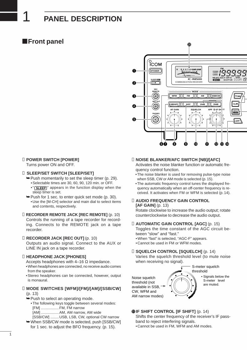
➊POWER SWITCH [POWER]Turns power ON and OFF.
➋ SLEEP/SET SWITCH [SLEEP/SET]Push momentarily to set the sleep timer (p. 29).
• Selectable times are 30, 60, 90, 120 min. or OFF.• “ ” appears in the function display when thesleep timer is set.
Push for 1 sec. to enter quick set mode (p. 30).•Use the [M-CH] selector and main dial to select itemsand contents, respectively.
➌RECORDER REMOTE JACK [REC REMOTE] (p. 10)Controls the running of a tape recorder for record-ing. Connects to the REMOTE jack on a taperecorder.
➍RECORDER JACK [REC OUT] (p. 10)Outputs an audio signal. Connect to the AUX orLINE IN jack on a tape recorder.
➎HEADPHONE JACK [PHONES]Accepts headphones with 4–16 Ω impedance.•When headphones are connected, no receive audio comesfrom the speaker.
•Stereo headphones can be connected, however, outputis monaural.
➏MODE SWITCHES [WFM]/[FM]/[AM]/[SSB/CW](p. 13)Push to select an operating mode.
•The following keys toggle between several modes:[FM] ................. FM, FM narrow[AM] .................AM, AM narrow, AM wide[SSB/CW] ........USB, LSB, CW, optional CW narrow
When SSB/CW mode is selected, push [SSB/CW]for 1 sec. to adjust the BFO frequency. (p. 15).
➐NOISE BLANKER/AFC SWITCH [NB]/[AFC]Activates the noise blanker function or automatic fre-quency control function.•The noise blanker is used for removing pulse-type noisewhen SSB, CW or AM mode is selected (p. 15).
•The automatic frequency control tunes the displayed fre-quency automatically when an off-center frequency is re-ceived. It activates when FM or WFM is selected (p. 14).
➑AUDIO FREQUENCY GAIN CONTROL[AF GAIN] (p. 13)Rotate clockwise to increase the audio output; rotatecounterclockwise to decrease the audio output.
➒AUTOMATIC GAIN CONTROL [AGC] (p. 15)Toggles the time constant of the AGC circuit be-tween “slow” and “fast.”•When “fast” is selected, “AGC-F” appears.•Cannot be used in FM or WFM modes.
➓SQUELCH CONTROL [SQUELCH] (p. 14)Varies the squelch threshold level (to mute noisewhen receiving no signal).
!1 IF SHIFT CONTROL [IF SHIFT] (p. 14)Shifts the center frequency of the receiver’s IF pass-band to reject interfering signals.•Cannot be used in FM, WFM and AM modes.
SLEEP
1
1 PANEL DESCRIPTION
MODE
WFM
NB/AFC AGC 10dB 20dB
FM AM
APF
TS
TS
SPCH
SSB/CW
AF GAIN SQUELCH
PHONES
REC OUT
SLEEP/
RECREMOTE
IF SHIFTAPF
SET
LOCK
COMMUNICATION RECEIVERiC-r8500
POWER
SIGNAL
S 1 3 5 7 9 +20dB+60dB
@0
q
w
e
r
t
y i o !0 !1 !2 !3 !4u
FM
RECVBANK
10-ATT-20APF-NAGC-FAFCNB
SLEEP
LOCK
ICOM I
S-meter squelchthreshold
Noise squelchthreshold (notavailable in SSB,CW, WFM andAM narrow modes)
• Signals below the S-meter level are muted.
Front panel
2
1PANEL DESCRIPTION
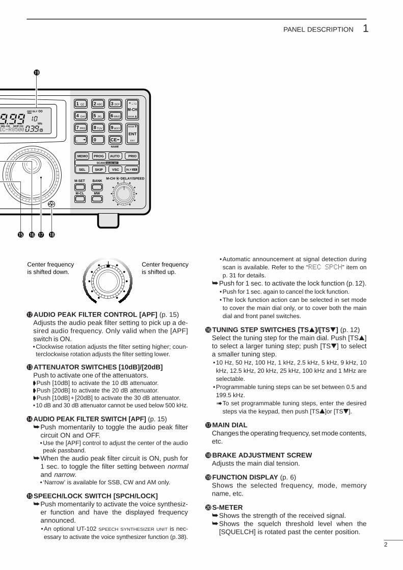
!2AUDIO PEAK FILTER CONTROL [APF] (p. 15)Adjusts the audio peak filter setting to pick up a de-sired audio frequency. Only valid when the [APF]switch is ON.•Clockwise rotation adjusts the filter setting higher; coun-terclockwise rotation adjusts the filter setting lower.
!3ATTENUATOR SWITCHES [10dB]/[20dB]Push to activate one of the attenuators.Push [10dB] to activate the 10 dB attenuator. Push [20dB] to activate the 20 dB attenuator. Push [10dB]+ [20dB] to activate the 30 dB attenuator.•10 dB and 30 dB attenuator cannot be used below 500 kHz.
!4AUDIO PEAK FILTER SWITCH [APF] (p. 15)Push momentarily to toggle the audio peak filter
circuit ON and OFF.•Use the [APF] control to adjust the center of the audiopeak passband.
When the audio peak filter circuit is ON, push for1 sec. to toggle the filter setting between normaland narrow.• ‘Narrow’ is available for SSB, CW and AM only.
!5SPEECH/LOCK SWITCH [SPCH/LOCK]Push momentarily to activate the voice synthesiz-
er function and have the displayed frequencyannounced.•An optional UT-102 SPEECH SYNTHESIZER UNIT is nec-essary to activate the voice synthesizer function (p.38).
•Automatic announcement at signal detection duringscan is available. Refer to the “REC SPCH” item onp. 31 for details.
Push for 1 sec. to activate the lock function (p.12).•Push for 1 sec. again to cancel the lock function.•The lock function action can be selected in set modeto cover the main dial only, or to cover both the maindial and front panel switches.
!6TUNING STEP SWITCHES [TS]/[TS] (p. 12)Select the tuning step for the main dial. Push [TS]to select a larger tuning step; push [TS] to selecta smaller tuning step.•10 Hz, 50 Hz, 100 Hz, 1 kHz, 2.5 kHz, 5 kHz, 9 kHz, 10kHz, 12.5 kHz, 20 kHz, 25 kHz, 100 kHz and 1 MHz areselectable.
•Programmable tuning steps can be set between 0.5 and199.5 kHz.To set programmable tuning steps, enter the desired
steps via the keypad, then push [TSY]or [TSZ].
!7MAIN DIALChanges the operating frequency, set mode contents,etc.
!8BRAKE ADJUSTMENT SCREWAdjusts the main dial tension.
!9FUNCTION DISPLAY (p. 6)Shows the selected frequency, mode, memoryname, etc.
@0S-METERShows the strength of the received signal.Shows the squelch threshold level when the
[SQUELCH] is rotated past the center position.
MEMO
SEL SKIP VSC DLY
SCAN/
NAME
SCAN SET
PROG AUTO PRIO
M-SET BANK
M-CL MW
DELAY/SPEEDM-CH
D/S
1 QZ
GHI
PRS TUV WXY
ENT
BANK
BANKJKL MNO
ABC DEF. ; ,
4
7 8
0 CEENT
M-CH
.
9
5 6
2 3
!9
!5 !6 !8!7
SEL-CH SKIP-CH
OFF
kHz
DLY ∞
MIC-R8500
Center frequency is shifted up.
Center frequency is shifted down.
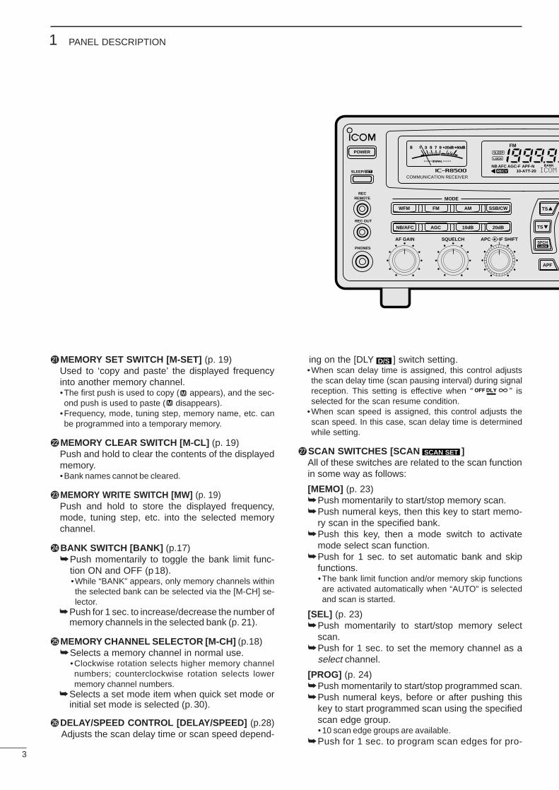
@1MEMORY SET SWITCH [M-SET] (p. 19)Used to ‘copy and paste’ the displayed frequencyinto another memory channel.•The first push is used to copy ( appears), and the sec-ond push is used to paste ( disappears).
•Frequency, mode, tuning step, memory name, etc. canbe programmed into a temporary memory.
@2MEMORY CLEAR SWITCH [M-CL] (p. 19)Push and hold to clear the contents of the displayedmemory.•Bank names cannot be cleared.
@3MEMORY WRITE SWITCH [MW] (p. 19)Push and hold to store the displayed frequency,mode, tuning step, etc. into the selected memorychannel.
@4BANK SWITCH [BANK] (p.17)Push momentarily to toggle the bank limit func-
tion ON and OFF (p18).•While “BANK” appears, only memory channels withinthe selected bank can be selected via the [M-CH] se-lector.
Push for 1 sec. to increase/decrease the number ofmemory channels in the selected bank (p. 21).
@5MEMORY CHANNEL SELECTOR [M-CH] (p.18)Selects a memory channel in normal use.
•Clockwise rotation selects higher memory channelnumbers; counterclockwise rotation selects lowermemory channel numbers.
Selects a set mode item when quick set mode orinitial set mode is selected (p.30).
@6DELAY/SPEED CONTROL [DELAY/SPEED] (p.28)Adjusts the scan delay time or scan speed depend-
ing on the [DLY ] switch setting.•When scan delay time is assigned, this control adjuststhe scan delay time (scan pausing interval) during signalreception. This setting is effective when “ ” isselected for the scan resume condition.
•When scan speed is assigned, this control adjusts thescan speed. In this case, scan delay time is determinedwhile setting.
@7SCAN SWITCHES [SCAN ]All of these switches are related to the scan functionin some way as follows:
[MEMO] (p. 23)Push momentarily to start/stop memory scan.Push numeral keys, then this key to start memo-
ry scan in the specified bank.Push this key, then a mode switch to activate
mode select scan function.Push for 1 sec. to set automatic bank and skip
functions.•The bank limit function and/or memory skip functionsare activated automatically when “AUTO” is selectedand scan is started.
[SEL] (p. 23)Push momentarily to start/stop memory select
scan.Push for 1 sec. to set the memory channel as a
select channel.
[PROG] (p. 24)Push momentarily to start/stop programmed scan.Push numeral keys, before or after pushing this
key to start programmed scan using the specifiedscan edge group.•10 scan edge groups are available.
Push for 1 sec. to program scan edges for pro-
SCAN SET
D/S
M
M
3
1 PANEL DESCRIPTION
MODE
WFM
NB/AFC AGC 10dB 20dB
FM AM
APF
TS
TS
SPCH
SSB/CW
AF GAIN SQUELCH
PHONES
REC OUT
SLEEP/
RECREMOTE
IF SHIFTAPC
SET
LOCK
COMMUNICATION RECEIVERiC-r8500
POWER
SIGNAL
S 1 3 5 7 9 +20dB+60dB FM
RECVBANK
10-ATT-20APF-NAGC-FAFCNB
SLEEP
LOCK
ICOM
4
1PANEL DESCRIPTION
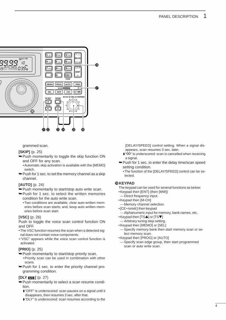
grammed scan.
[SKIP] (p. 25)Push momentarily to toggle the skip function ON
and OFF for any scan.•Automatic skip activation is available with the [MEMO]switch.
Push for 1 sec. to set the memory channel as a skipchannel.
[AUTO] (p. 24)Push momentarily to start/stop auto write scan.Push for 1 sec. to select the written memories
condition for the auto write scan.•Two conditions are available, clear auto-written mem-ories before scan starts; and, keep auto written mem-ories before scan start.
[VSC] (p. 26)Push to toggle the voice scan control function ONand OFF.•The VSC function resumes the scan when a detected sig-nal does not contain voice components.
• “VSC” appears while the voice scan control function isactivated.
[PRIO] (p. 25)Push momentarily to start/stop priority scan.
•Priority scan can be used in combination with otherscans.
Push for 1 sec. to enter the priority channel pro-gramming condition.
[DLY ] (p. 27)Push momentarily to select a scan resume condi-
tion. “OFF” is underscored: scan pauses on a signal until it
disappears, then resumes 3 sec. after that. “DLY” is underscored: scan resumes according to the
[DELAY/SPEED] control setting. When a signal dis-appears, scan resumes 3 sec. later.
“∞” is underscored: scan is cancelled when receivinga signal.
Push for 1 sec. to enter the delay time/scan speedsetting condition.•The function of the [DELAY/SPEED] control can be se-lected.
@8KEYPADThe keypad can be used for several functions as below:•Keypad then [ENT] (then [MW])—Direct frequency input.
•Keypad then [M-CH]—Memory channel selection.
• [CE• NAME] then keypad—Alphanumeric input for memory, bank names, etc.
•Keypad then [TSY] or [TSZ]—Arbitrary tuning step setting.
•Keypad then [MEMO] or [SEL]—Specify memory bank then start memory scan or se-
lect memory scan.•Keypad then [PROG] or [AUTO]—Specify scan edge group, then start programmed
scan or auto write scan.
D/S
MEMO
SEL SKIP VSC DLY
SCAN/
NAME
SCAN SET
PROG AUTO PRIO
M-SET BANK
M-CL MW
DELAY/SPEEDM-CH
D/S
1 QZ
GHI
PRS TUV WXY
ENT
BANK
BANKJKL MNO
ABC DEF. ; ,
4
7 8
0 CEENT
M-CH
.
9
5 6
2 3
@2 @3@1 @4 @5 @6
@7
@8SEL-CH SKIP-CH
OFF
kHz
DLY ∞
MIC-R8500
5
1 PANEL DESCRIPTION
Rear panel
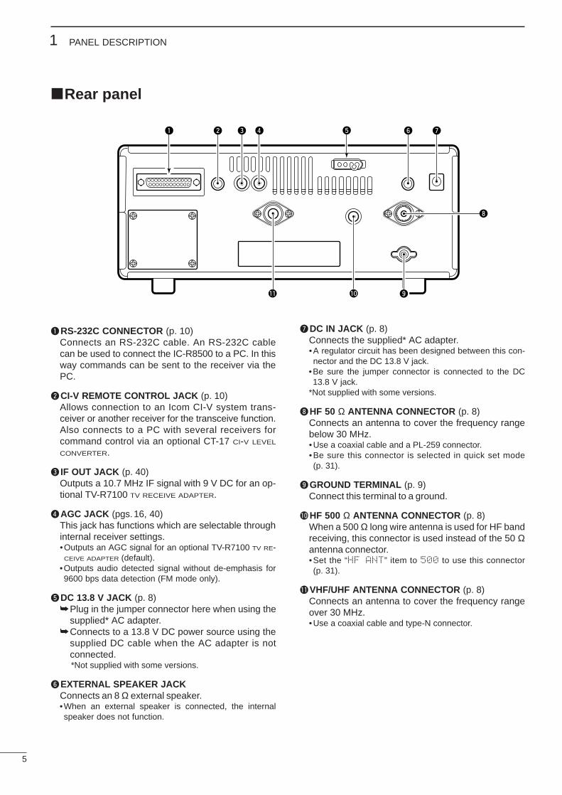
qRS-232C CONNECTOR (p. 10)Connects an RS-232C cable. An RS-232C cablecan be used to connect the IC-R8500 to a PC. In thisway commands can be sent to the receiver via thePC.
wCI-V REMOTE CONTROL JACK (p. 10)Allows connection to an Icom CI-V system trans-ceiver or another receiver for the transceive function.Also connects to a PC with several receivers forcommand control via an optional CT-17 CI-V LEVEL
CONVERTER.
e IF OUT JACK (p. 40)Outputs a 10.7 MHz IF signal with 9 V DC for an op-tional TV-R7100 TV RECEIVE ADAPTER.
rAGC JACK (pgs.16, 40)This jack has functions which are selectable throughinternal receiver settings.•Outputs an AGC signal for an optional TV-R7100 TV RE-
CEIVE ADAPTER (default).•Outputs audio detected signal without de-emphasis for9600 bps data detection (FM mode only).
tDC 13.8 V JACK (p. 8)Plug in the jumper connector here when using the
supplied* AC adapter.Connects to a 13.8 V DC power source using the
supplied DC cable when the AC adapter is notconnected.*Not supplied with some versions.
yEXTERNAL SPEAKER JACKConnects an 8 Ω external speaker.•When an external speaker is connected, the internalspeaker does not function.
uDC IN JACK (p. 8)Connects the supplied* AC adapter.•A regulator circuit has been designed between this con-nector and the DC 13.8 V jack.
•Be sure the jumper connector is connected to the DC13.8 V jack.
*Not supplied with some versions.
iHF 50 Ω ANTENNA CONNECTOR (p. 8)Connects an antenna to cover the frequency rangebelow 30 MHz.•Use a coaxial cable and a PL-259 connector.•Be sure this connector is selected in quick set mode(p. 31).
oGROUND TERMINAL (p. 9)Connect this terminal to a ground.
!0HF 500 Ω ANTENNA CONNECTOR (p. 8)When a 500 Ω long wire antenna is used for HF bandreceiving, this connector is used instead of the 50 Ωantenna connector.•Set the “HF ANT” item to 500 to use this connector(p. 31).
!1VHF/UHF ANTENNA CONNECTOR (p. 8)Connects an antenna to cover the frequency rangeover 30 MHz.•Use a coaxial cable and type-N connector.
q
w e r y ut
o
i
!0!1
6
1PANEL DESCRIPTION
Function display
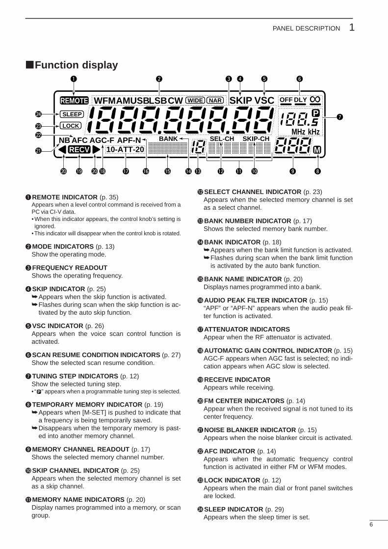
qREMOTE INDICATOR (p. 35)Appears when a level control command is received from aPC via CI-V data.•When this indicator appears, the control knob’s setting isignored.
•This indicator will disappear when the control knob is rotated.
wMODE INDICATORS (p. 13)Show the operating mode.
eFREQUENCY READOUTShows the operating frequency.
rSKIP INDICATOR (p. 25) Appears when the skip function is activated.Flashes during scan when the skip function is ac-
tivated by the auto skip function.
tVSC INDICATOR (p. 26)Appears when the voice scan control function isactivated.
ySCAN RESUME CONDITION INDICATORS (p. 27)Show the selected scan resume condition.
uTUNING STEP INDICATORS (p. 12)Show the selected tuning step.• “ ” appears when a programmable tuning step is selected.
iTEMPORARY MEMORY INDICATOR (p. 19)Appears when [M-SET] is pushed to indicate that
a frequency is being temporarily saved.Disappears when the temporary memory is past-
ed into another memory channel.
oMEMORY CHANNEL READOUT (p. 17)Shows the selected memory channel number.
!0SKIP CHANNEL INDICATOR (p. 25)Appears when the selected memory channel is setas a skip channel.
!1MEMORY NAME INDICATORS (p. 20)Display names programmed into a memory, or scangroup.
!2SELECT CHANNEL INDICATOR (p. 23)Appears when the selected memory channel is setas a select channel.
!3BANK NUMBER INDICATOR (p. 17)Shows the selected memory bank number.
!4BANK INDICATOR (p. 18)Appears when the bank limit function is activated.Flashes during scan when the bank limit function
is activated by the auto bank function.
!5BANK NAME INDICATOR (p. 20)Displays names programmed into a bank.
!6AUDIO PEAK FILTER INDICATOR (p. 15)“APF” or “APF-N” appears when the audio peak fil-ter function is activated.
!7ATTENUATOR INDICATORSAppear when the RF attenuator is activated.
!8AUTOMATIC GAIN CONTROL INDICATOR (p. 15)AGC-F appears when AGC fast is selected; no indi-cation appears when AGC slow is selected.
!9RECEIVE INDICATORAppears while receiving.
@0FM CENTER INDICATORS (p. 14)Appear when the received signal is not tuned to itscenter frequency.
@1NOISE BLANKER INDICATOR (p. 15)Appears when the noise blanker circuit is activated.
@2AFC INDICATOR (p. 14)Appears when the automatic frequency controlfunction is activated in either FM or WFM modes.
@3LOCK INDICATOR (p. 12)Appears when the main dial or front panel switchesare locked.
@4SLEEP INDICATOR (p. 29)Appears when the sleep timer is set.
P
REMOTE WFM
RECV
AMUSBLSBCW
BANK
10-ATT-20APF-NAGC-FAFCNB SEL-CH SKIP-CH
WIDE NAR SKIP VSC OFF
MHz kHz
DLY ∞SLEEP
LOCK
M
P
q w e r t y
u
io!0!1!2!3!4!5!6!7!8!9@0 @0
@1
@2
@3
@4

7
2 CONNECTIONS
Mounting installation
DLocationSelect a location for the receiver that allows adequateair circulation and access to the front and rear panels.Do not place in areas subject to extreme heat, cold, orvibrations, or near TV sets, radios and electromagneticsources.
Be careful of the internal temperature of the receiver.Installation into a rack or other enclosed area may in-crease the internal temperature over the useable tem-perature range. Specifications are not guaranteedunder such conditions.
DReceiver standThe base of the IC-R8500 has an adjustable stand fordesktop use. Set the stand to one of two angles de-pending on your operating conditions.
DOptional bracket and carrying handle• Mounting bracketAn optional mounting bracket is available to install theradio under a table, on a wall, in a vehicle, etc.
Select an area to mount the receiver keeping in mindthat the weight of the IC-R8500 is approx. 7 kg.
• Carrying handleAn optional handle allows you to easily carry andtransport the receiver.
Attach the MB-23 CARRYING HANDLE with the suppliedrubber feet as shown.
CAUTION: The screws supplied with the MB-23cannot be used with the IC-R8500. Use the screwssupplied with the IC-R8500 when attaching theMB-23.
Flat washer
Springwasher
Allen boltsupplied withthe IC-R8500.
8
2CONNECTIONS
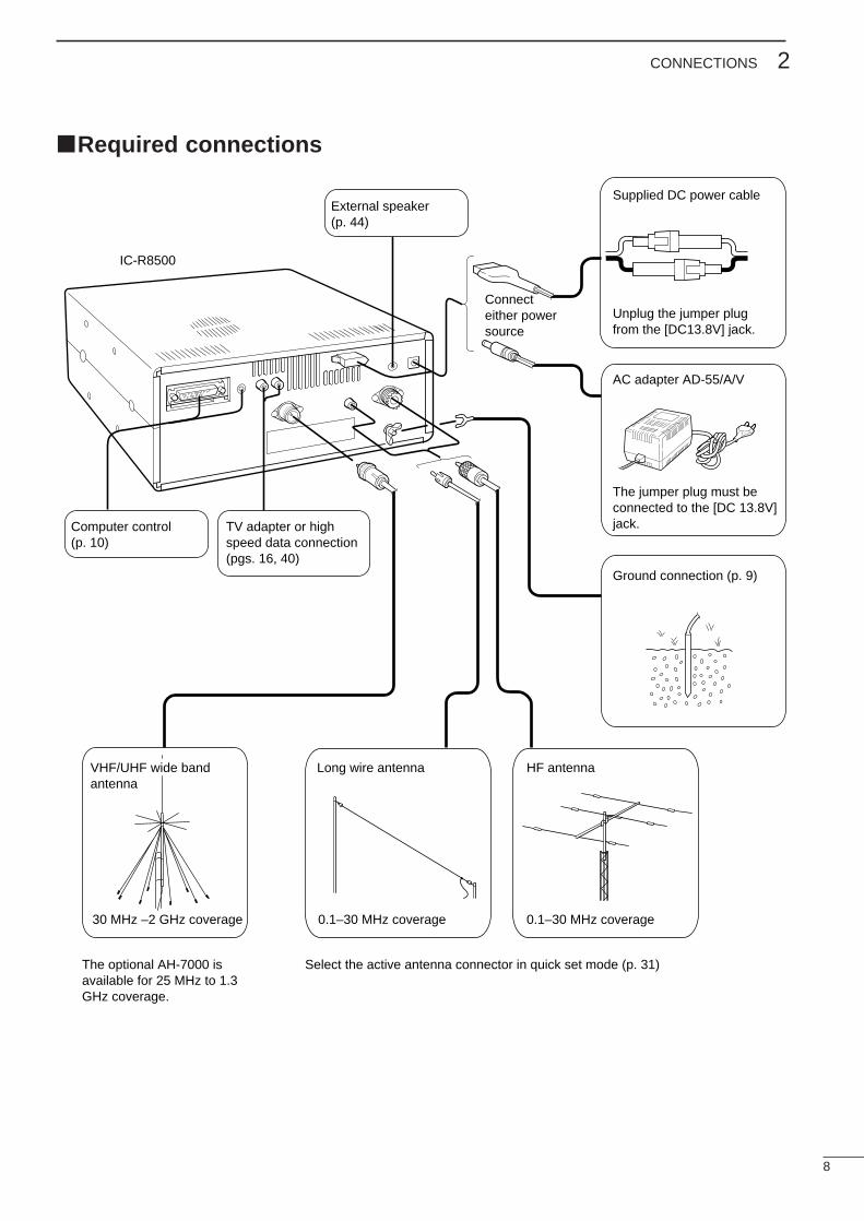
Required connections
IC-R8500
Supplied DC power cable
Unplug the jumper plugfrom the [DC13.8V] jack.
AC adapter AD-55/A/V
Connecteither powersource
The jumper plug must beconnected to the [DC 13.8V]jack.
Ground connection (p. 9)
HF antennaLong wire antennaVHF/UHF wide bandantenna
Computer control(p. 10)
External speaker(p. 44)
TV adapter or highspeed data connection(pgs. 16, 40)
0.1–30 MHz coverage0.1–30 MHz coverage30 MHz –2 GHz coverage
The optional AH-7000 is available for 25 MHz to 1.3 GHz coverage.
Select the active antenna connector in quick set mode (p. 31)
9
2 CONNECTIONS
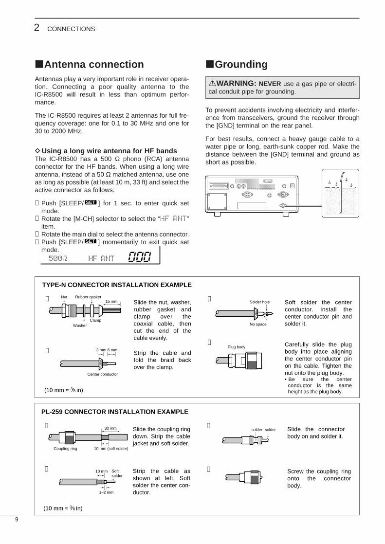
Antenna connectionAntennas play a very important role in receiver opera-tion. Connecting a poor quality antenna to theIC-R8500 will result in less than optimum perfor-mance.
The IC-R8500 requires at least 2 antennas for full fre-quency coverage: one for 0.1 to 30 MHz and one for30 to 2000 MHz.
DUsing a long wire antenna for HF bandsThe IC-R8500 has a 500 Ω phono (RCA) antennaconnector for the HF bands. When using a long wireantenna, instead of a 50 Ω matched antenna, use oneas long as possible (at least 10 m, 33 ft) and select theactive connector as follows:
➀Push [SLEEP/ ] for 1 sec. to enter quick setmode.
➁Rotate the [M-CH] selector to select the “HF ANT”item.
➂Rotate the main dial to select the antenna connector.➃Push [SLEEP/ ] momentarily to exit quick set
mode.
Grounding
To prevent accidents involving electricity and interfer-ence from transceivers, ground the receiver throughthe [GND] terminal on the rear panel.
For best results, connect a heavy gauge cable to awater pipe or long, earth-sunk copper rod. Make thedistance between the [GND] terminal and ground asshort as possible.
SET
SET
RWARNING: NEVER use a gas pipe or electri-cal conduit pipe for grounding.
30 mm
10 mm (soft solder)
10 mm
1–2 mm
solder solder
Softsolder
Coupling ring
PL-259 CONNECTOR INSTALLATION EXAMPLE
➀ ➂
➃➁
Slide the coupling ring down. Strip the cable jacket and soft solder.
Slide the connector body on and solder it.
Screw the coupling ring onto the connector body.
Strip the cable as shown at left. Soft solder the center con-ductor.
(10 mm ≈ 3⁄8 in)
15 mm
Clamp
3 mm 6 mm
Center conductor
Washer
Nut Rubber gasket
TYPE-N CONNECTOR INSTALLATION EXAMPLE
➀ ➂
➃➁
Slide the nut, washer, rubber gasket and clamp over the coaxial cable, then cut the end of the cable evenly.
Soft solder the center conductor. Install the center conductor pin and solder it.
Carefully slide the plug body into place aligning the center conductor pin on the cable. Tighten the nut onto the plug body.• Be sure the center
conductor is the same height as the plug body.
Strip the cable and fold the braid back over the clamp.
(10 mm ≈ 3⁄8 in)
Plug body
No space
Solder hole
500 HF ANT
10
2CONNECTIONS
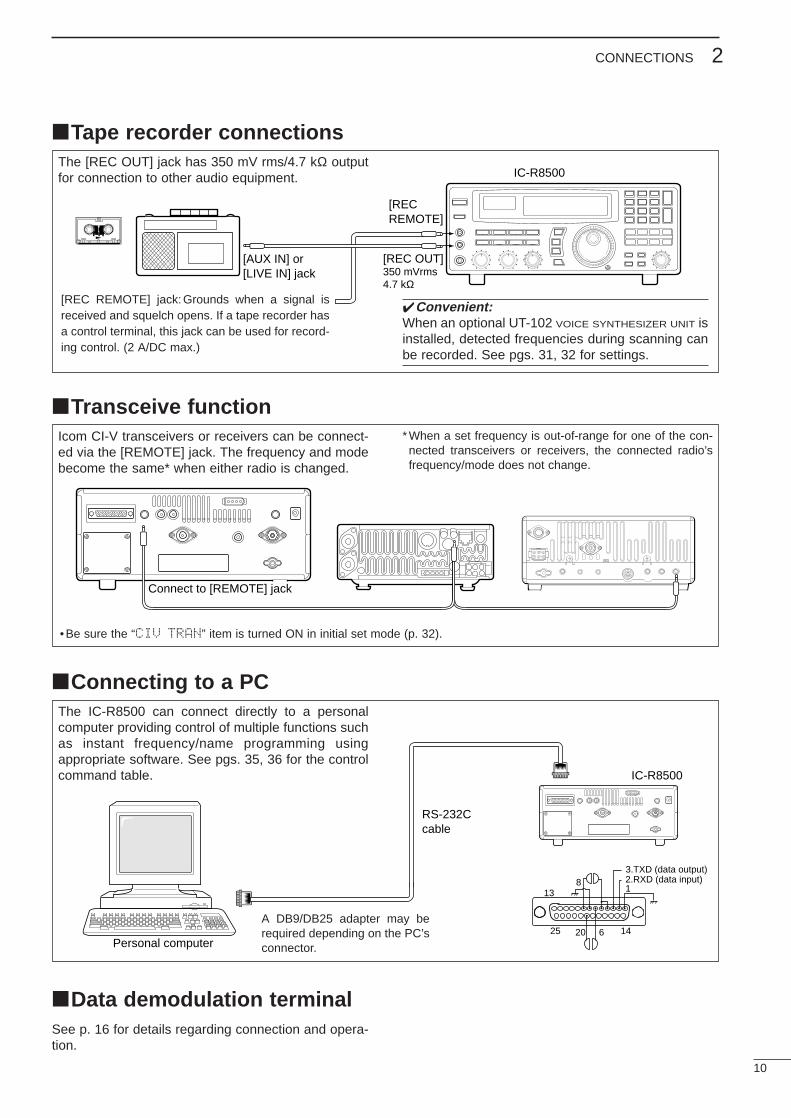
Tape recorder connectionsThe [REC OUT] jack has 350 mV rms/4.7 kΩ outputfor connection to other audio equipment.
Transceive functionIcom CI-V transceivers or receivers can be connect-ed via the [REMOTE] jack. The frequency and modebecome the same* when either radio is changed.
*When a set frequency is out-of-range for one of the con-nected transceivers or receivers, the connected radio’sfrequency/mode does not change.
Connecting to a PC
Data demodulation terminalSee p. 16 for details regarding connection and opera-tion.
The IC-R8500 can connect directly to a personalcomputer providing control of multiple functions suchas instant frequency/name programming usingappropriate software. See pgs. 35, 36 for the controlcommand table.
Personal computer
IC-R8500
RS-232Ccable
13
25 14
2.RXD (data input)3.TXD (data output)
1
20 6
8
IC-R8500
SCAN SET
[RECREMOTE]
[REC OUT]350 mVrms4.7 kΩ
[AUX IN] or[LIVE IN] jack
Convenient:When an optional UT-102 VOICE SYNTHESIZER UNIT isinstalled, detected frequencies during scanning canbe recorded. See pgs. 31, 32 for settings.
[REC REMOTE] jack:Grounds when a signal isreceived and squelch opens. If a tape recorder hasa control terminal, this jack can be used for record-ing control. (2 A/DC max.)
Connect to [REMOTE] jack
•Be sure the “CIV TRAN” item is turned ON in initial set mode (p. 32).
A DB9/DB25 adapter may berequired depending on the PC’sconnector.
11
3 FREQUENCY SETTING
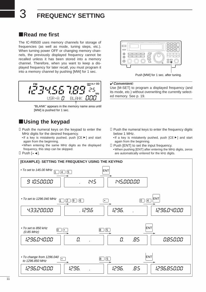
Read me firstThe IC-R8500 uses memory channels for storage offrequencies (as well as mode, tuning steps, etc.).When turning power OFF or changing memory chan-nels, the previously displayed frequency cannot berecalled unless it has been stored into a memorychannel. Therefore, when you want to keep a dis-played frequency for later recall, you must program itinto a memory channel by pushing [MW] for 1 sec.
Convenient:Use [M-SET] to program a displayed frequency (andits mode, etc.) without overwriting the currently select-ed memory. See p. 19.
Using the keypad➀Push the numeral keys on the keypad to enter the
MHz digits for the desired frequency.• If a key is mistakenly pushed, push [CEs] and startagain from the beginning.
•When entering the same MHz digits as the displayedfrequency, this step can be skipped.
➁Push [ •t].
➂Push the numeral keys to enter the frequency digitsbelow 1 MHz.• If a key is mistakenly pushed, push [CEs] and startagain from the beginning.
➃Push [ENT] to set the input frequency.•When pushing [ENT] after entering the MHz digits, zerosare automatically entered for the kHz digits.
[EXAMPLE]: SETTING THE FREQUENCY USING THE KEYPAD
• To set to 145.00 MHz1 4 5 ENT
• To set to 1296.040 MHz1 2 9 6 • 0 4
ENT
• To set to 850 kHz (0.85 MHz)
0 8 5•ENT
• To change from 1296.040 to 1296.850 MHz
8 5•ENT
Push [MW] for 1 sec. after tuning.
FM OFF
kHz
DLY ∞
USR-A BLANK
“BLANK” appears in the memory name area until[MW] is pushed for 1 sec.
12
3FREQUENCY SETTING
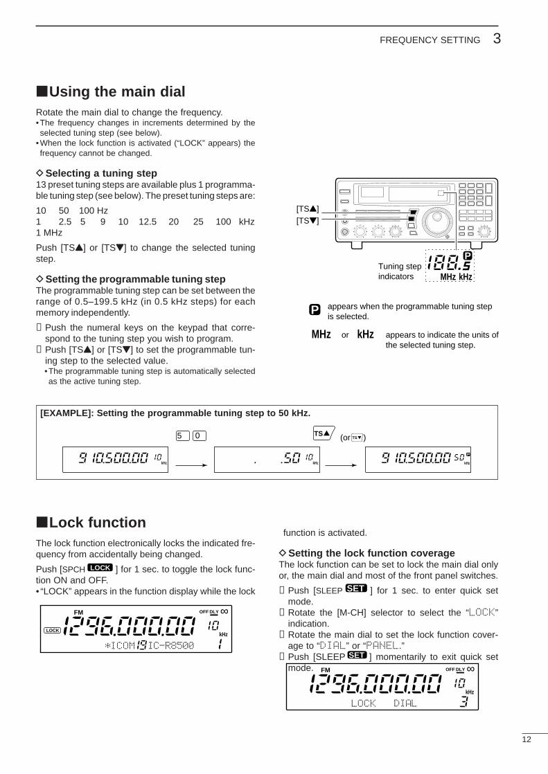
Using the main dialRotate the main dial to change the frequency.•The frequency changes in increments determined by theselected tuning step (see below).
•When the lock function is activated (“LOCK” appears) thefrequency cannot be changed.
DSelecting a tuning step13 preset tuning steps are available plus 1 programma-ble tuning step (see below). The preset tuning steps are:
10 50 100 Hz1 2.5 5 9 10 12.5 20 25 100 kHz1 MHz
Push [TSY] or [TSZ] to change the selected tuningstep.
DSetting the programmable tuning stepThe programmable tuning step can be set between therange of 0.5–199.5 kHz (in 0.5 kHz steps) for eachmemory independently.
➀Push the numeral keys on the keypad that corre-spond to the tuning step you wish to program.
➁Push [TSY] or [TSZ] to set the programmable tun-ing step to the selected value.•The programmable tuning step is automatically selectedas the active tuning step.
Lock functionThe lock function electronically locks the indicated fre-quency from accidentally being changed.
Push [SPCH ] for 1 sec. to toggle the lock func-tion ON and OFF.• “LOCK” appears in the function display while the lock
function is activated.
DSetting the lock function coverageThe lock function can be set to lock the main dial onlyor, the main dial and most of the front panel switches.
➀Push [SLEEP ] for 1 sec. to enter quick setmode.
➁Rotate the [M-CH] selector to select the “LOCK”indication.
➂Rotate the main dial to set the lock function cover-age to “DIAL” or “PANEL.”
➃Push [SLEEP ] momentarily to exit quick setmode.
SET
SET
LOCK
SCAN SET
[TSY][TSZ]
MHz kHz
PTuning stepindicators
MHz kHz
P appears when the programmable tuning stepis selected.
or appears to indicate the units ofthe selected tuning step.
[EXAMPLE]: Setting the programmable tuning step to 50 kHz.
(or )
kHz
P
kHzkHz
5 0 TSTS
FM
kHzLOCK
*ICOM IC-R8500
OFF DLY ∞
LOCK DIAL
kHz
FM OFF DLY ∞
13
4 RECEIVE FUNCTIONS
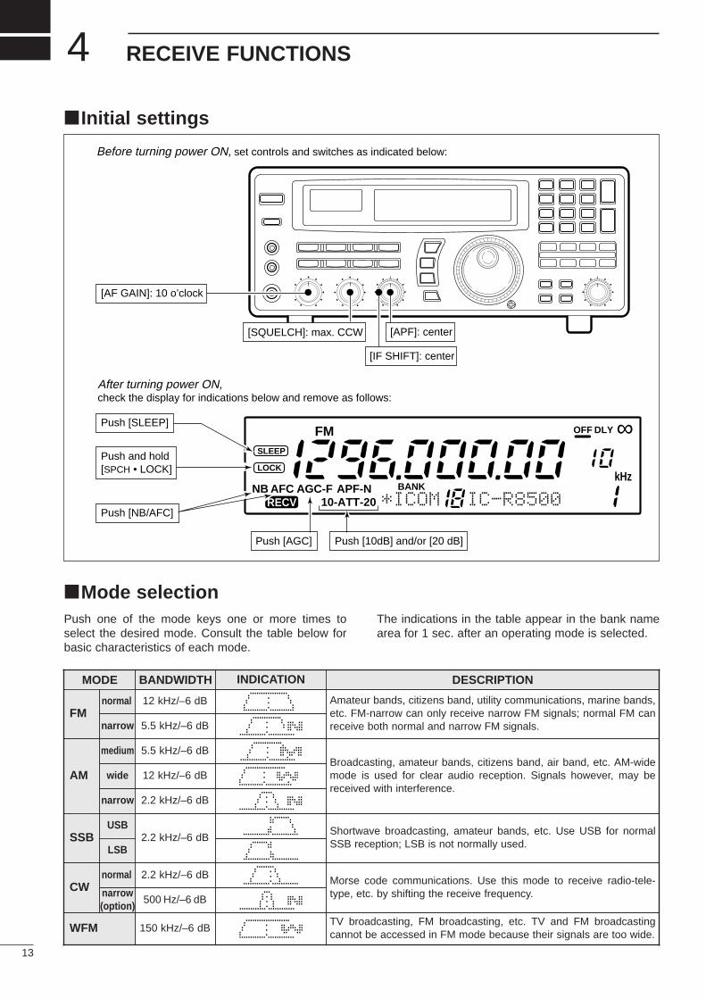
Initial settings
Mode selectionPush one of the mode keys one or more times toselect the desired mode. Consult the table below forbasic characteristics of each mode.
The indications in the table appear in the bank namearea for 1 sec. after an operating mode is selected.
SCAN SET
FM
RECVBANK
10-ATT-20APF-NAGC-FAFCNB
OFF
kHz
DLY ∞SLEEP
LOCK
*ICOM IC-R8500
[AF GAIN]: 10 o’clock
[APF]: center
[IF SHIFT]: center
Push [SLEEP]
Push [NB/AFC]
Push [AGC] Push [10dB] and/or [20 dB]
Push and hold[SPCH • LOCK]
Before turning power ON, set controls and switches as indicated below:
After turning power ON,check the display for indications below and remove as follows:
[SQUELCH]: max. CCW
MODE BANDWIDTH INDICATION DESCRIPTION
FM12 kHz/–6 dB Amateur bands, citizens band, utility communications, marine bands,
etc. FM-narrow can only receive narrow FM signals; normal FM canreceive both normal and narrow FM signals.
AM
5.5 kHz/–6 dBBroadcasting, amateur bands, citizens band, air band, etc. AM-widemode is used for clear audio reception. Signals however, may bereceived with interference.
SSB 2.2 kHz/–6 dBShortwave broadcasting, amateur bands, etc. Use USB for normalSSB reception; LSB is not normally used.
CW2.2 kHz/–6 dB Morse code communications. Use this mode to receive radio-tele-
type, etc. by shifting the receive frequency.
WFM 150 kHz/–6 dBTV broadcasting, FM broadcasting, etc. TV and FM broadcastingcannot be accessed in FM mode because their signals are too wide.
5.5 kHz/–6 dB
normal
narrow
2.2 kHz/–6 dB
medium
narrow
12 kHz/–6 dBwide
USB
LSB
normal
500 Hz/–6 dBnarrow(option)
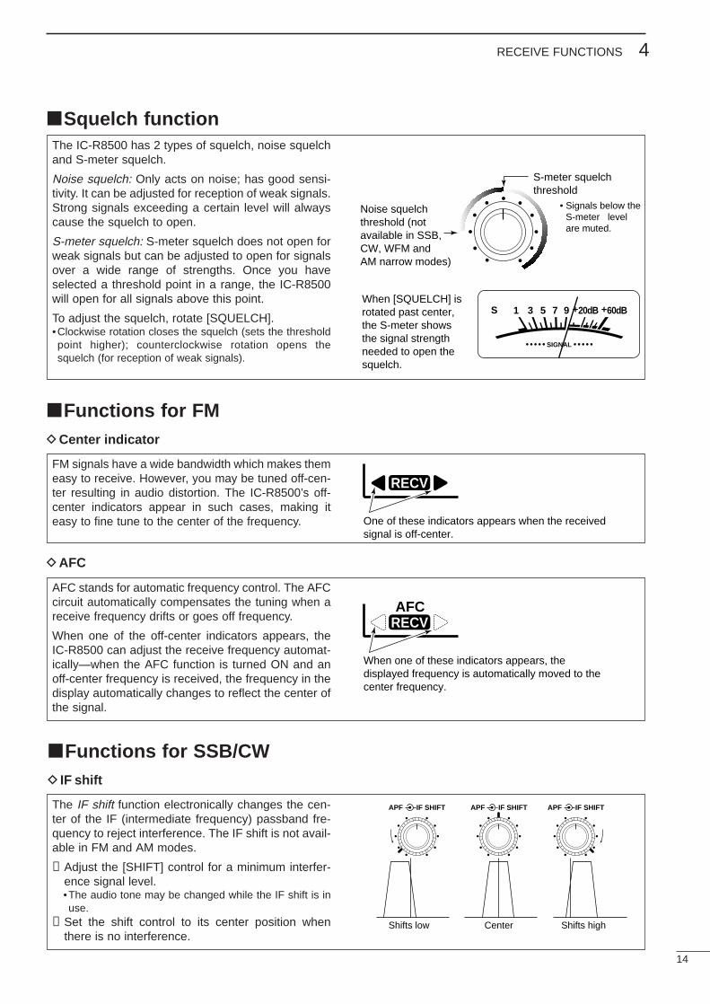
The IC-R8500 has 2 types of squelch, noise squelchand S-meter squelch.
Noise squelch: Only acts on noise; has good sensi-tivity. It can be adjusted for reception of weak signals.Strong signals exceeding a certain level will alwayscause the squelch to open.
S-meter squelch: S-meter squelch does not open forweak signals but can be adjusted to open for signalsover a wide range of strengths. Once you haveselected a threshold point in a range, the IC-R8500will open for all signals above this point.
To adjust the squelch, rotate [SQUELCH].•Clockwise rotation closes the squelch (sets the thresholdpoint higher); counterclockwise rotation opens thesquelch (for reception of weak signals).
FM signals have a wide bandwidth which makes themeasy to receive. However, you may be tuned off-cen-ter resulting in audio distortion. The IC-R8500’s off-center indicators appear in such cases, making iteasy to fine tune to the center of the frequency.
AFC stands for automatic frequency control. The AFCcircuit automatically compensates the tuning when areceive frequency drifts or goes off frequency.
When one of the off-center indicators appears, theIC-R8500 can adjust the receive frequency automat-ically—when the AFC function is turned ON and anoff-center frequency is received, the frequency in thedisplay automatically changes to reflect the center ofthe signal.
14
4RECEIVE FUNCTIONS
Squelch function
Functions for FMDCenter indicator
S-meter squelchthreshold
Noise squelchthreshold (notavailable in SSB,CW, WFM andAM narrow modes)
• Signals below the S-meter level are muted.
When [SQUELCH] isrotated past center,the S-meter showsthe signal strengthneeded to open the squelch.
SIGNAL
S 1 3 5 7 9 +20dB +60dB
RECV
One of these indicators appears when the received signal is off-center.
RECV
When one of these indicators appears, the displayed frequency is automatically moved to the center frequency.
AFC
DAFC
The IF shift function electronically changes the cen-ter of the IF (intermediate frequency) passband fre-quency to reject interference. The IF shift is not avail-able in FM and AM modes.
➀Adjust the [SHIFT] control for a minimum interfer-ence signal level.•The audio tone may be changed while the IF shift is inuse.
➁Set the shift control to its center position whenthere is no interference.
Functions for SSB/CWD IF shift
Shifts low Center Shifts high
IF SHIFTAPFIF SHIFTAPF IF SHIFTAPF
15
4 RECEIVE FUNCTIONS
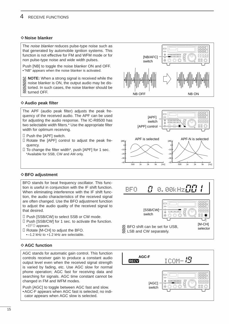
The noise blanker reduces pulse-type noise such asthat generated by automobile ignition systems. Thisfunction is not effective for FM and WFM mode or fornon pulse-type noise and wide width pulses.
Push [NB] to toggle the noise blanker ON and OFF.• “NB” appears when the noise blanker is activated.
NOTE: When a strong signal is received while thenoise blanker is ON, the output audio may be dis-torted. In such cases, the noise blanker should beturned OFF.
The APF (audio peak filter) adjusts the peak fre-quency of the received audio. The APF can be usedfor adjusting the audio response. The IC-R8500 hastwo selectable width filters.* Use the appropriate filterwidth for optimum receiving.
➀Push the [APF] switch.➁Rotate the [APF] control to adjust the peak fre-
quency.➂To change the filter width*, push [APF] for 1 sec.
*Available for SSB, CW and AM only.
BFO stands for beat frequency oscillator. This func-tion is useful in conjunction with the IF shift function.When eliminating interference with the IF shift func-tion, the audio characteristics of the received signalare often changed. Use the BFO adjustment functionto adjust the audio quality of the received signal tothat desired.
➀Push [SSB/CW] to select SSB or CW mode.➁Push [SSB/CW] for 1 sec. to activate the function.
•BFO appears.➂Rotate [M-CH] to adjust the BFO.
•–1.2 kHz to +1.2 kHz are selectable.
AGC stands for automatic gain control. This functioncontrols receiver gain to produce a constant audiooutput level even when the received signal strengthis varied by fading, etc. Use AGC slow for normalphone operation; AGC fast for receiving data andsearching for signals. AGC time constant cannot bechanged in FM and WFM modes.
Push [AGC] to toggle between AGC fast and slow.•AGC-F appears when AGC fast is selected; no indi-cator appears when AGC slow is selected.
DNoise blanker
DAudio peak filter
DBFO adjustment
DAGC function
BFO 0.00kHz
ICOM-RECVAGC-F
NB OFF NB ON
500 1k 2k 5k [Hz]–40
–30
–20
–10
0
[dB]
500 1k 2k 5k [Hz]–40
–30
–20
–10
0
[dB]APF is selected APF-N is selected
[NB/AFC]switch
SCAN SET
[APF] control
[APF]switch SCAN SET
[SSB/CW]switch
SCAN SET
[M-CH]selector
[AGC]switch
SCAN SET
BFO shift can be set for USB,LSB and CW separately.
TU or TNC AF IN
SQUELCH IN
to [REC OUT]
to [REC REMOTE]
SCAN SET
2-conductor 3.5(d) plugsPersonal computer
16
4RECEIVE FUNCTIONS
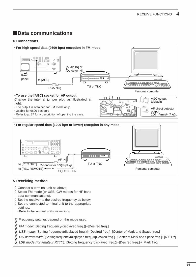
Data communicationsDConnections
DReceiving method
• To use the [AGC] socket for AF outputChange the internal jumper plug as illustrated atright.•The output is obtained for FM mode only.•Usable for 9600 bps only.•Refer to p. 37 for a description of opening the case.
➀Connect a terminal unit as above.➁Select FM mode (or USB, CW modes for HF band
data communications).➂Set the receiver to the desired frequency as below.➃Set the connected terminal unit to the appropriate
settings.•Refer to the terminal unit’s instructions.
Rearpanel
TU or TNC
to [AGC]
RCA plugPersonal computer
[Audio IN] or[Detector IN]
• For high speed data (9600 bps) reception in FM mode
• For regular speed data (1200 bps or lower) reception in any mode
Frequency settings depend on the mode used.
FM mode: [Setting frequency(displayed freq.)]=[Desired freq.]
USB mode: [Setting frequency(displayed freq.)]=[Desired freq.]–[Center of Mark and Space freq.]
CW narrow mode: [Setting frequency(displayed freq.)]=[Desired freq.]–[Center of Mark and Space freq.]+ [600 Hz]
LSB mode (for amateur RTTY): [Setting frequency(displayed freq.)]=[Desired freq.] + [Mark freq.]
AGC output(default)
AF direct detectoroutput200 mVrms/4.7 kΩ
17
5 MEMORY CHANNELS
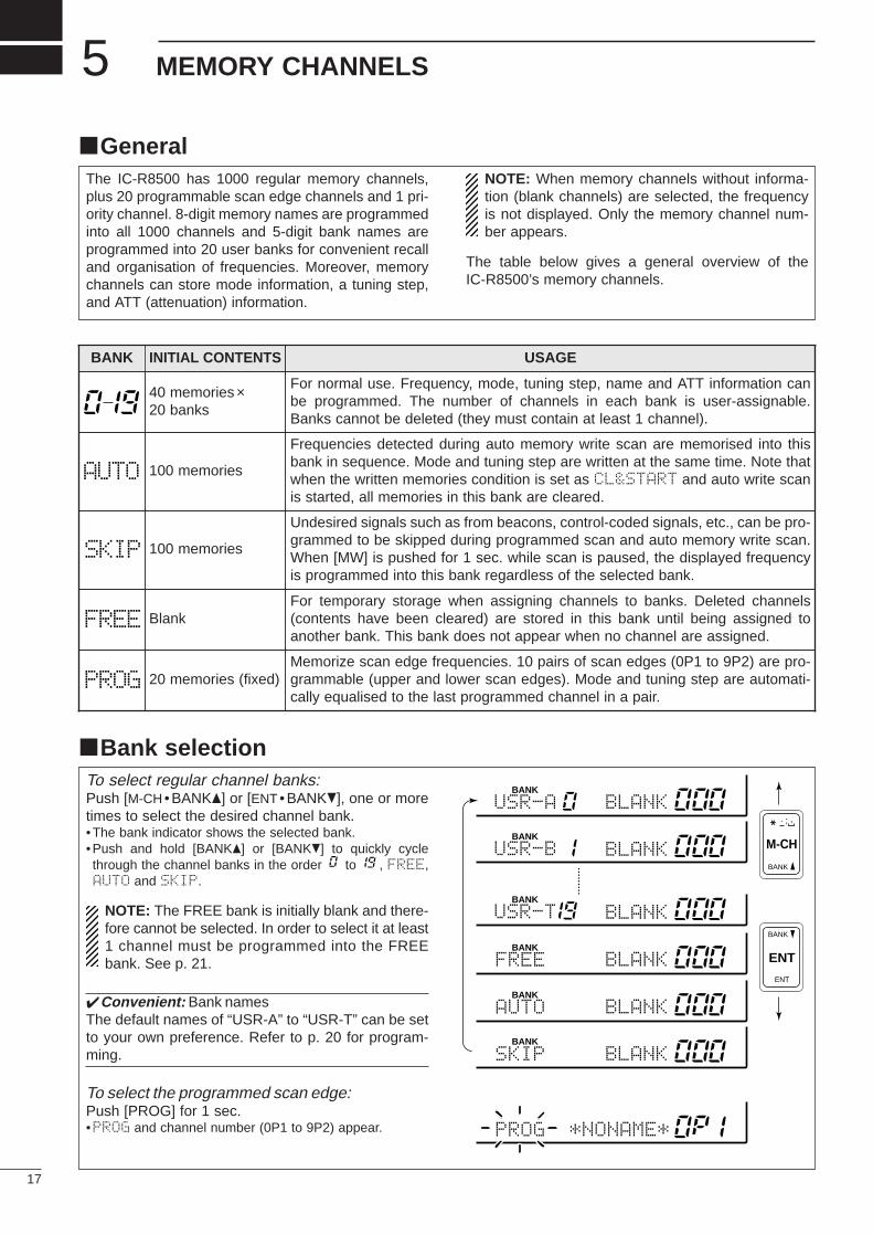
To select regular channel banks:Push [M-CH •BANK] or [ENT • BANK], one or moretimes to select the desired channel bank.•The bank indicator shows the selected bank.•Push and hold [BANK] or [BANK] to quickly cyclethrough the channel banks in the order to , FREE,AUTO and SKIP.
NOTE: The FREE bank is initially blank and there-fore cannot be selected. In order to select it at least1 channel must be programmed into the FREEbank. See p. 21.
Convenient: Bank namesThe default names of “USR-A” to “USR-T” can be setto your own preference. Refer to p. 20 for program-ming.
To select the programmed scan edge:Push [PROG] for 1 sec.•PROG and channel number (0P1 to 9P2) appear.
Bank selection
The IC-R8500 has 1000 regular memory channels,plus 20 programmable scan edge channels and 1 pri-ority channel. 8-digit memory names are programmedinto all 1000 channels and 5-digit bank names areprogrammed into 20 user banks for convenient recalland organisation of frequencies. Moreover, memorychannels can store mode information, a tuning step,and ATT (attenuation) information.
NOTE: When memory channels without informa-tion (blank channels) are selected, the frequencyis not displayed. Only the memory channel num-ber appears.
The table below gives a general overview of theIC-R8500’s memory channels.
BANK INITIAL CONTENTS USAGE
40 memories×20 banks
For normal use. Frequency, mode, tuning step, name and ATT information canbe programmed. The number of channels in each bank is user-assignable.Banks cannot be deleted (they must contain at least 1 channel).
100 memories
Frequencies detected during auto memory write scan are memorised into thisbank in sequence. Mode and tuning step are written at the same time. Note thatwhen the written memories condition is set as CL&START and auto write scanis started, all memories in this bank are cleared.
100 memories
Undesired signals such as from beacons, control-coded signals, etc., can be pro-grammed to be skipped during programmed scan and auto memory write scan.When [MW] is pushed for 1 sec. while scan is paused, the displayed frequencyis programmed into this bank regardless of the selected bank.
BlankFor temporary storage when assigning channels to banks. Deleted channels(contents have been cleared) are stored in this bank until being assigned toanother bank. This bank does not appear when no channel are assigned.
20 memories (fixed)Memorize scan edge frequencies. 10 pairs of scan edges (0P1 to 9P2) are pro-grammable (upper and lower scan edges). Mode and tuning step are automati-cally equalised to the last programmed channel in a pair.
General
ENT
BANK
BANK
. ; ,
ENT
M-CH
BANK
BANK
BANK
BANK
USR-A BLANK
BLANK
BLANK
BLANK
USR-B
BANK
BLANKUSR-T
AUTO
BANK
BLANKFREE
SKIP
*NONAME*PROG
AUTO
SKIP
FREE
PROG
18
5MEMORY CHANNELS
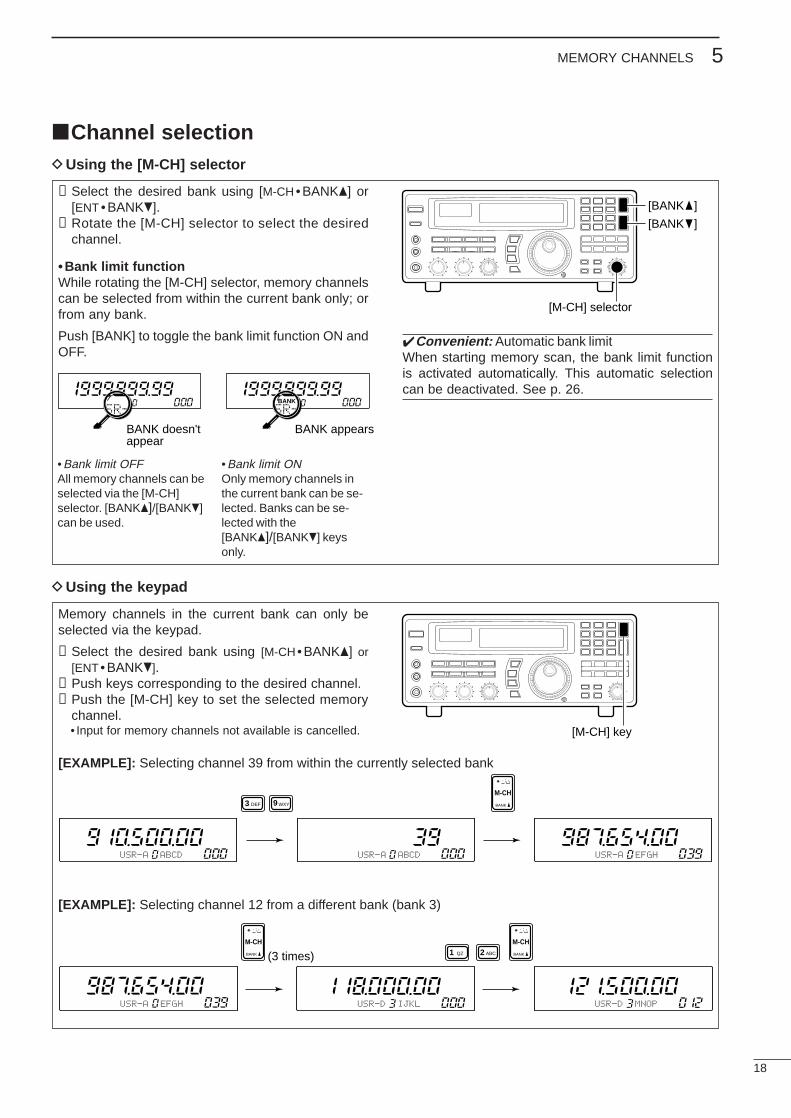
➀Select the desired bank using [M-CH • BANK] or[ENT • BANK].
➁Rotate the [M-CH] selector to select the desiredchannel.
• Bank limit functionWhile rotating the [M-CH] selector, memory channelscan be selected from within the current bank only; orfrom any bank.
Push [BANK] to toggle the bank limit function ON andOFF.
Convenient: Automatic bank limitWhen starting memory scan, the bank limit functionis activated automatically. This automatic selectioncan be deactivated. See p. 26.
Memory channels in the current bank can only beselected via the keypad.
➀Select the desired bank using [M-CH•BANK] or[ENT• BANK].
➁Push keys corresponding to the desired channel.➂Push the [M-CH] key to set the selected memory
channel.• Input for memory channels not available is cancelled.
Channel selectionDUsing the [M-CH] selector
DUsing the keypad
[M-CH] selector
[BANK ]
[BANK ]
[M-CH] key
[EXAMPLE]: Selecting channel 39 from within the currently selected bank
BANK
MUSR-A
BANK appearsBANK doesn'tappear
BANK
MUSR-A BANK
SR-SR-
•Bank limit OFFAll memory channels can beselected via the [M-CH]selector. [BANK]/[BANK]can be used.
•Bank limit ONOnly memory channels inthe current bank can be se-lected. Banks can be se-lected with the[BANK]/[BANK] keysonly.
USR-A ABCD USR-A ABCD USR-A EFGH
WXY BANKDEF
. ; ,
M-CH93
[EXAMPLE]: Selecting channel 12 from a different bank (bank 3)
USR-A EFGH USR-D IJKL USR-D MNOP
BANK
. ; ,
M-CH
BANK
. ; ,
M-CH
1 QZ ABC2(3 times)
19
5 MEMORY CHANNELS
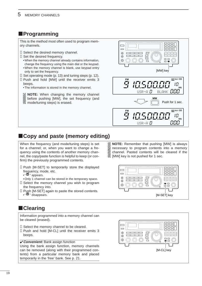
ProgrammingThis is the method most often used to program mem-ory channels.
➀Select the desired memory channel.➁Set the desired frequency.
•When the memory channel already contains information,change the frequency using the main dial or the keypad.
•When the memory channel is blank, use keypad entryonly to set the frequency.
➂Set operating mode (p. 13) and tuning steps (p. 12).➃Push and hold [MW] until the receiver emits 3
beeps.•The information is stored in the memory channel.
NOTE: When changing the memory channelbefore pushing [MW], the set frequency (andmode/tuning steps) is erased.
Copy and paste (memory editing)When the frequency (and mode/tuning steps) is setfor a channel; or, when you want to change a fre-quency using the contents of another memory chan-nel, the copy/paste function is helpful to keep (or con-firm) the previously programmed contents.
➀Push [M-SET] to temporarily store the displayedfrequency, mode, etc.• “ ” appears.•Only 1 channel can be stored in the temporary space.
➁Select the memory channel you wish to programthe frequency into.
➂Push [M-SET] again to paste the stored contents.• “ ” disappears.
NOTE: Remember that pushing [MW] is alwaysnecessary to program contents into a memorychannel. Pasted contents will be cleared if the[MW] key is not pushed for 1 sec.
M
M
ClearingInformation programmed into a memory channel canbe cleared (erased).
➀Select the memory channel to be cleared.➁Push and hold [M-CL] until the receiver emits 3
beeps.
Convenient: Bank assign functionUsing the bank assign function, memory channelscan be removed (along with their programmed con-tents) from a particular memory bank and placedtemporarily in the ‘free’ bank. See p. 21.
[MW] key
Push for 1 sec.
USR-A
USR-A
BLANK
MW
FM OFF
kHz
DLY ∞
FM OFF
kHz
DLY ∞
[M-SET] key
[M-CL] key
20
5MEMORY CHANNELS
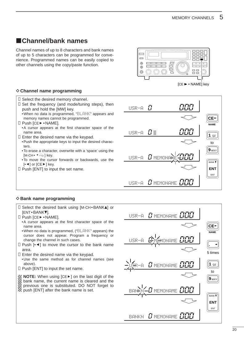
Channel/bank namesChannel names of up to 8 characters and bank namesof up to 5 characters can be programmed for conve-nience. Programmed names can be easily copied toother channels using the copy/paste function.
➀Select the desired memory channel.➁Set the frequency (and mode/tuning steps), then
push and hold the [MW] key.•When no data is programmed, “BLANK” appears andmemory names cannot be programmed.
➂Push [CEs • NAME].•A cursor appears at the first character space of thename area.
➃Enter the desired name via the keypad.•Push the appropriate keys to input the desired charac-ters.
•To erase a character, overwrite with a ‘space’ using the[M-CH • ] key.
•To move the cursor forwards or backwards, use the[•t] or [CEs] key.
➄Push [ENT] to input the set name.
➀Select the desired bank using [M-CH • BANK] or[ENT • BANK].
➁Push [CEs •NAME].•A cursor appears at the first character space of thename area.
•When no data is programmed, (“BLANK” appears) thecursor does not appear. Program a frequency orchange the channel in such cases.
➂Push [•t] to move the cursor to the bank namearea.
➃Enter the desired name via the keypad.•Use the same method as for channel names (seeabove).
➄Push [ENT] to input the set name.
NOTE: When using [CEs] on the last digit of thebank name, the current name is cleared and theprevious one is substituted. DO NOT forget topush [ENT] after the bank name is set.
[CEs• NAME] key
1 QZ
ENT
BANK
ENT
WXY9
NAME
CE
to
USR-A
USR-A
USR-A MEMONAME
USR-A MEMONAME
DChannel name programming
DBank name programming
USR-A
USR-A
USR-A MEMONAME
MEMONAME
MEMONAME
BANKN MEMONAME
BANKN MEMONAME
ENT
BANK
ENT
.
NAME
CE
5 times
1 QZ
WXY9
to
21
5 MEMORY CHANNELS
Assigning channel numbersThe IC-R8500 has 20 banks in which memory chan-nels can be programmed and arranged. By default,each bank contains 40 memory channels, however,channels can be deleted from or added (inserted) tobanks to suit your preferences and operating style.
Deleted channels are stored temporarily in the“FREE” bank.
NOTE: When shipped from the factory or afterresetting the receiver’s CPU, the “FREE” bank hasno memory channels and cannot be selected.
To rearrange bank channel assignments:➀Delete memory channels from banks that have
more memory channels than you need.•Deleted channels are assigned to the ‘free’ bank auto-matically.
➁Add (or insert) memory channels to banks in whichyou want to add channels.•Channels added to a bank are deleted from the ‘free’bank.
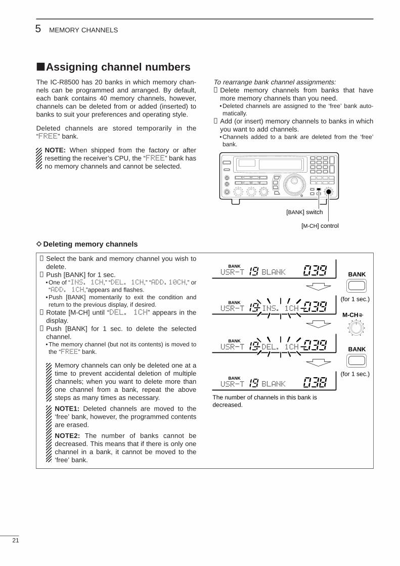
➀Select the bank and memory channel you wish todelete.
➁Push [BANK] for 1 sec.•One of “INS. 1CH,” “DEL. 1CH,” “ADD.10CH,” or“ADD. 1CH,”appears and flashes.
•Push [BANK] momentarily to exit the condition andreturn to the previous display, if desired.
➂Rotate [M-CH] until “DEL. 1CH” appears in thedisplay.
➃Push [BANK] for 1 sec. to delete the selectedchannel.•The memory channel (but not its contents) is moved tothe “FREE” bank.
Memory channels can only be deleted one at atime to prevent accidental deletion of multiplechannels; when you want to delete more thanone channel from a bank, repeat the abovesteps as many times as necessary.
NOTE1: Deleted channels are moved to the‘free’ bank, however, the programmed contentsare erased.
NOTE2: The number of banks cannot bedecreased. This means that if there is only onechannel in a bank, it cannot be moved to the‘free’ bank.
DDeleting memory channels
[BANK] switch
[M-CH] control
USR-T DEL. 1CH
BLANKUSR-T
BANK
BANK
BANK
(for 1 sec.)
The number of channels in this bank isdecreased.
USR-T BLANK
INS. 1CHUSR-T
BANK
BANK
BANK
M-CH
(for 1 sec.)
22
5MEMORY CHANNELS
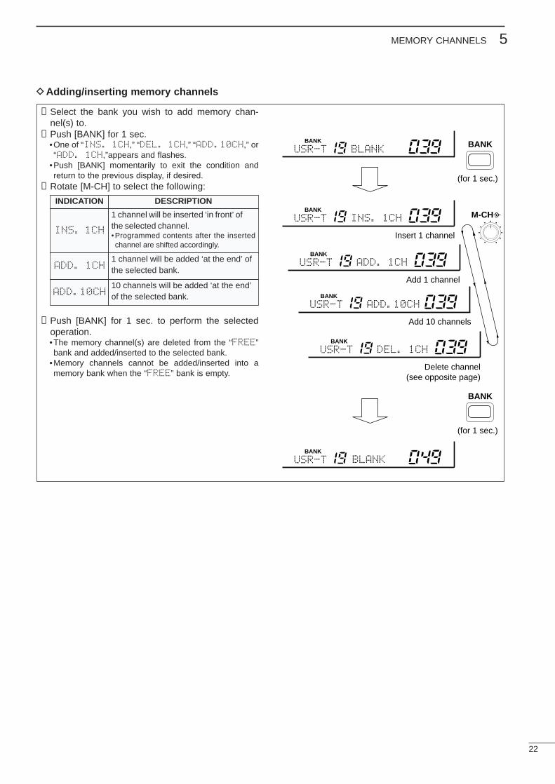
➀Select the bank you wish to add memory chan-nel(s) to.
➁Push [BANK] for 1 sec.•One of “INS. 1CH,” “DEL. 1CH,” “ADD.10CH,” or“ADD. 1CH,”appears and flashes.
•Push [BANK] momentarily to exit the condition andreturn to the previous display, if desired.
➂Rotate [M-CH] to select the following:
➃Push [BANK] for 1 sec. to perform the selectedoperation.•The memory channel(s) are deleted from the “FREE”bank and added/inserted to the selected bank.
•Memory channels cannot be added/inserted into amemory bank when the “FREE” bank is empty.
DAdding/inserting memory channels
USR-T BLANK
USR-T
BANK
BANK
INS. 1CH
USR-TBANK
BLANK
Insert 1 channel
USR-TBANK
ADD. 1CH
Add 1 channel
USR-TBANK
ADD.10CH
Add 10 channels
USR-TBANK
DEL. 1CH
Delete channel(see opposite page)
BANK
M-CH
(for 1 sec.)
BANK
(for 1 sec.)
INDICATION DESCRIPTION
INS. 1CH
1 channel will be inserted ‘in front’ ofthe selected channel.•Programmed contents after the insertedchannel are shifted accordingly.
ADD. 1CH1 channel will be added ‘at the end’ ofthe selected bank.
ADD.10CH10 channels will be added ‘at the end’of the selected bank.
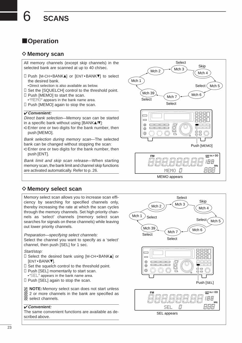
Operation
DMemory scan
DMemory select scan
23
6 SCANS
All memory channels (except skip channels) in theselected bank are scanned at up to 40 ch/sec.
➀Push [M-CH • BANK] or [ENT • BANK] to selectthe desired bank.•Direct selection is also available as below.
➁Set the [SQUELCH] control to the threshold point.➂Push [MEMO] to start the scan.
• “MEMO” appears in the bank name area.➃Push [MEMO] again to stop the scan.
Convenient:Direct bank selection—Memory scan can be startedin a specific bank without using [BANK/]:Enter one or two digits for the bank number, then
push [MEMO].
Bank selection during memory scan—The selectedbank can be changed without stopping the scan:Enter one or two digits for the bank number, then
push [ENT].
Bank limit and skip scan release—When startingmemory scan, the bank limit and channel skip functionsare activated automatically. Refer to p. 26.
Memory select scan allows you to increase scan effi-ciency by searching for specified channels only,thereby increasing the rate at which the scan cyclesthrough the memory channels. Set high priority chan-nels as ‘select’ channels (memory select scansearches for signals on these channels) while leavingout lower priority channels.
Preparation—specifying select channels:Select the channel you want to specify as a ‘select’channel, then push [SEL] for 1 sec.
Start/stop:➀Select the desired bank using [M-CH • BANK] or
[ENT •BANK].➁Set the squelch control to the threshold point.➂Push [SEL] momentarily to start scan.
• “SEL” appears in the bank name area.➃Push [SEL] again to stop the scan.
NOTE: Memory select scan does not start unless2 or more channels in the bank are specified asselect channels.
Convenient:The same convenient functions are available as de-scribed above.
Mch 1
Mch 2 Mch 3Mch 4
Mch 5
Mch 6Mch 7Mch 39
SkipSelect
Select
SelectSelect
Push [MEMO]
FM OFF
kHz
DLY ∞
MEMO
MEMO appears
Push [SEL]
FM OFF
kHz
DLY ∞
SEL
SEL appears
Mch 1
Mch 2 Mch 3Mch 4
Mch 5
Mch 6Mch 7Mch 39
SkipSelect
SelectSelect
SelectSelect
24
6SCANS
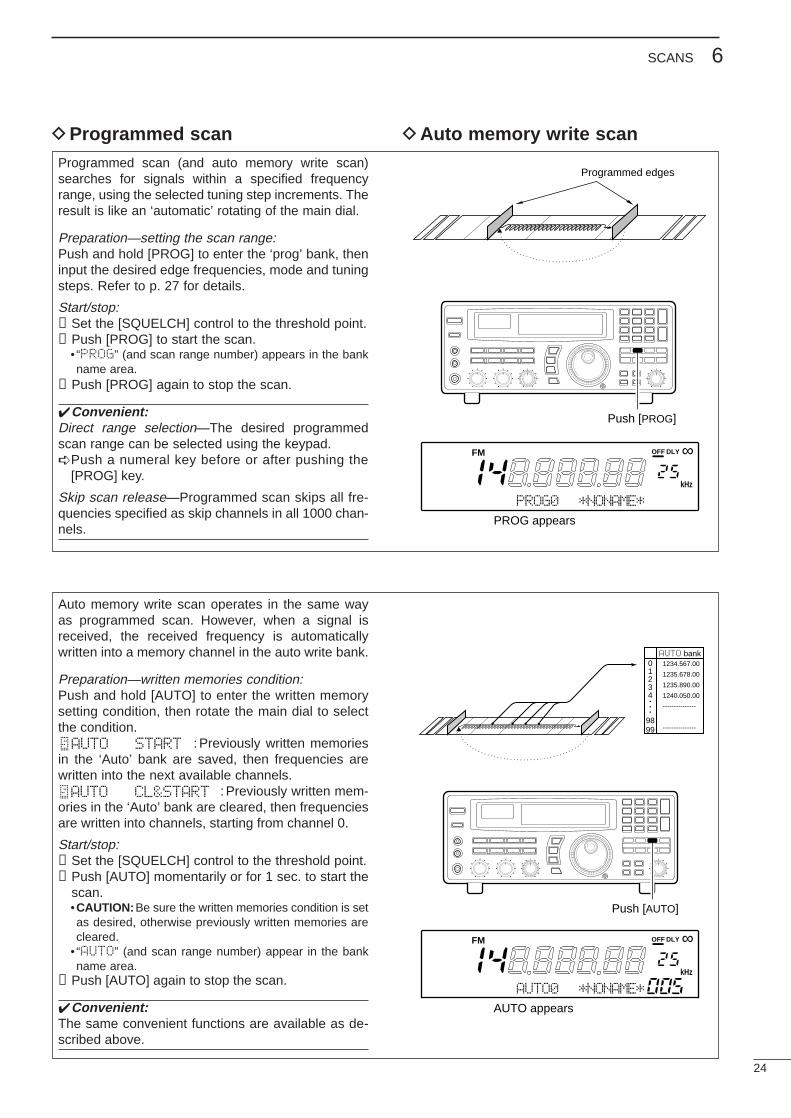
DProgrammed scan DAuto memory write scanProgrammed scan (and auto memory write scan)searches for signals within a specified frequencyrange, using the selected tuning step increments. Theresult is like an ‘automatic’ rotating of the main dial.
Preparation—setting the scan range:Push and hold [PROG] to enter the ‘prog’ bank, theninput the desired edge frequencies, mode and tuningsteps. Refer to p. 27 for details.
Start/stop:➀Set the [SQUELCH] control to the threshold point.➁Push [PROG] to start the scan.
• “PROG” (and scan range number) appears in the bankname area.
➂Push [PROG] again to stop the scan.
Convenient:Direct range selection—The desired programmedscan range can be selected using the keypad.Push a numeral key before or after pushing the
[PROG] key.
Skip scan release—Programmed scan skips all fre-quencies specified as skip channels in all 1000 chan-nels.
Auto memory write scan operates in the same wayas programmed scan. However, when a signal isreceived, the received frequency is automaticallywritten into a memory channel in the auto write bank.
Preparation—written memories condition:Push and hold [AUTO] to enter the written memorysetting condition, then rotate the main dial to selectthe condition.
: Previously written memoriesin the ‘Auto’ bank are saved, then frequencies arewritten into the next available channels.
: Previously written mem-ories in the ‘Auto’ bank are cleared, then frequenciesare written into channels, starting from channel 0.
Start/stop:➀Set the [SQUELCH] control to the threshold point.➁Push [AUTO] momentarily or for 1 sec. to start the
scan.•CAUTION: Be sure the written memories condition is setas desired, otherwise previously written memories arecleared.
• “AUTO” (and scan range number) appear in the bankname area.
➂Push [AUTO] again to stop the scan.
Convenient:The same convenient functions are available as de-scribed above.
Programmed edges
Push [PROG]
FM OFF
kHz
DLY ∞
PROG0 *NONAME*
PROG appears
AUTO bank01234•••
9899
1234.567.00
1235.678.00
1235.890.00
1240.050.00
---------------
---------------
Push [AUTO]
FM OFF
kHz
DLY ∞
AUTO0 *NONAME*
AUTO appears
AUTO START
AUTO CL&START
25
6 SCANS
DPriority scan
Priority scan monitors a specified frequency (the pri-ority channel) once every 1–16 sec. (programmable)during any operation, such as receiving, scanningother channels, etc.
Preparation—priority channel programming:➀Push [PRIO] for 1 sec.
• “*SET*” appears in the bank name area, thenchanges to a flashing “PRIO.”
•Using this method, the priority channel can be called upat any time with one push.
➁Set the desired frequency, mode and memoryname.
➂Push [MW] for 1 sec. to write the contents into thepriority channel.
➃Push [PRIO] again to return to the previous chan-nel.
Start/stop:Push [PRIO] to start/stop the scan.•Priority scan can be used in combination with other scantypes: start another scan type during priority scan; or,push [PRIO] while operating another scan.
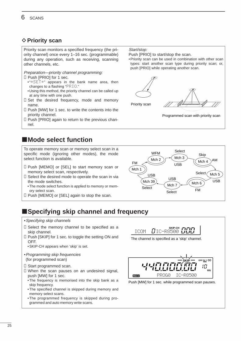
To operate memory scan or memory select scan in aspecific mode (ignoring other modes), the modeselect function is available.
➀Push [MEMO] or [SEL] to start memory scan ormemory select scan, respectively.
➁Select the desired mode to operate the scan in viathe mode switches.•The mode select function is applied to memory or mem-ory select scan.
➂Push [MEMO] or [SEL] again to stop the scan.
Priority scan
Programmed scan with priority scan
Mode select function
• Specifying skip channels
➀Select the memory channel to be specified as askip channel.
➁Push [SKIP] for 1 sec. to toggle the setting ON andOFF.•SKIP-CH appears when ‘skip’ is set.
•Programming skip frequencies(for programmed scan)
➀Start programmed scan.➁When the scan pauses on an undesired signal,
push [MW] for 1 sec.•The frequency is memorised into the skip bank as askip frequency.
•The specified channel is skipped during memory andmemory select scans.
•The programmed frequency is skipped during pro-grammed and auto memory write scans.
Specifying skip channel and frequency
ICOM IC-R8500SKIP-CH
SKIP
kHz
The channel is specified as a ‘skip’ channel.
Push [MW] for 1 sec. while programmed scan pauses.
PROG0 IC-R8500RECV
OFF DLY ∞
Mch 1
Mch 2 Mch 3Mch 4
Mch 5
Mch 6Mch 7Mch 39
SkipSelect
FM
FM
WFM
USB
USBUSB
AM
USB
Select
SelectSelect
26
6SCANS
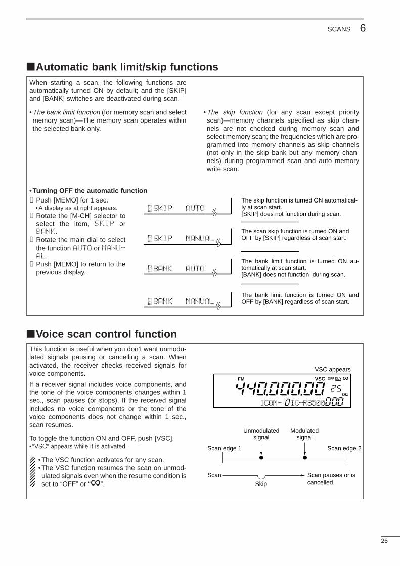
Automatic bank limit/skip functionsWhen starting a scan, the following functions areautomatically turned ON by default; and the [SKIP]and [BANK] switches are deactivated during scan.
•The bank limit function (for memory scan and selectmemory scan)—The memory scan operates withinthe selected bank only.
• Turning OFF the automatic function➀Push [MEMO] for 1 sec.
•A display as at right appears.➁Rotate the [M-CH] selector to
select the item, SKIP orBANK.
➂Rotate the main dial to selectthe function AUTO or MANU-AL.
➃Push [MEMO] to return to theprevious display.
SKIP AUTO
SKIP MANUAL
BANK AUTO
BANK MANUAL
The skip function is turned ON automatical-ly at scan start.[SKIP] does not function during scan.
The bank limit function is turned ON au-tomatically at scan start.[BANK] does not function during scan.
The scan skip function is turned ON and OFF by [SKIP] regardless of scan start.
The bank limit function is turned ON and OFF by [BANK] regardless of scan start.
Voice scan control functionThis function is useful when you don’t want unmodu-lated signals pausing or cancelling a scan. Whenactivated, the receiver checks received signals forvoice components.
If a receiver signal includes voice components, andthe tone of the voice components changes within 1sec., scan pauses (or stops). If the received signalincludes no voice components or the tone of thevoice components does not change within 1 sec.,scan resumes.
To toggle the function ON and OFF, push [VSC].• “VSC” appears while it is activated.
•The VSC function activates for any scan.•The VSC function resumes the scan on unmod-ulated signals even when the resume condition isset to “OFF” or “∞”.
Scan edge 1
ScanSkip
Scan pauses or iscancelled.
Unmodulatedsignal
Modulatedsignal
Scan edge 2
FM VSC OFF
kHz
DLY ∞
ICOM- IC-R8500
VSC appears
•The skip function (for any scan except priorityscan)—memory channels specified as skip chan-nels are not checked during memory scan andselect memory scan; the frequencies which are pro-grammed into memory channels as skip channels(not only in the skip bank but any memory chan-nels) during programmed scan and auto memorywrite scan.
27
6 SCANS
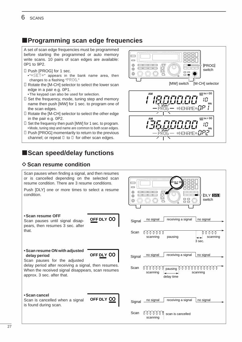
Programming scan edge frequenciesA set of scan edge frequencies must be programmedbefore starting the programmed or auto memorywrite scans. 10 pairs of scan edges are available:0P1 to 9P2.
➀Push [PROG] for 1 sec.• “*SET*” appears in the bank name area, thenchanges to a flashing “PROG.”
➁Rotate the [M-CH] selector to select the lower scanedge in a pair e.g. 0P1.•The keypad can also be used for selection.
➂Set the frequency, mode, tuning step and memoryname then push [MW] for 1 sec. to program one ofthe scan edges.
➃Rotate the [M-CH] selector to select the other edgein the pair e.g. 0P2.
➄Set the frequency then push [MW] for 1 sec. to program.•Mode, tuning step and name are common to both scan edges.
➅Push [PROG] momentarily to return to the previouschannel; or repeat ➁ to ➅ for other scan edges.
Scan pauses when finding a signal, and then resumesor is cancelled depending on the selected scanresume condition. There are 3 resume conditions.
Push [DLY] one or more times to select a resumecondition.
• Scan resume OFFScan pauses until signal disap-pears, then resumes 3 sec. afterthat.
•Scan resume ON with adjusteddelay period
Scan pauses for the adjusteddelay period after receiving a signal, then resumes.When the received signal disappears, scan resumesapprox. 3 sec. after that.
• Scan cancelScan is cancelled when a signalis found during scan.
Scan speed/delay functions
DScan resume condition
Signal no signal
scanning scanningpausing3 sec.
receiving a signal no signal
Scan
[ ]switch
OFF DLY ∞
DLY D/S
OFF DLY ∞
Signal no signal
scanning scanningpausing
delay time
receiving a signal no signal
Scan
OFF DLY ∞
Signal no signal
scanningscan is cancelled
receiving a signal no signal
Scan
OFF DLY ∞
[ ]switchPROG
[MW] switch [M-CH] selector
AM
BANK
OFF
kHz
DLY ∞
PROG *NONAME*
AM
BANK
OFF
kHz
DLY ∞
PROG *NONAME*
28
6SCANS
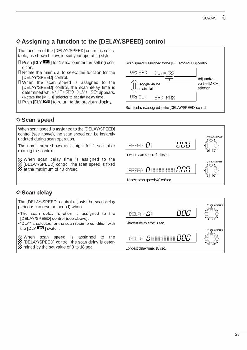
When scan speed is assigned to the [DELAY/SPEED]control (see above), the scan speed can be instantlyupdated during scan operation.
The name area shows as at right for 1 sec. afterrotating the control.
When scan delay time is assigned to the[DELAY/SPEED] control, the scan speed is fixedat the maximum of 40 ch/sec.
Highest scan speed: 40 ch/sec.
Lowest scan speed: 1 ch/sec.
SPEED
SPEED
DELAY/SPEED
DELAY/SPEED
The [DELAY/SPEED] control adjusts the scan delayperiod (scan resume period) when:
•The scan delay function is assigned to the[DELAY/SPEED] control (see above).
• “DLY” is selected for the scan resume condition withthe [DLY ] switch.
When scan speed is assigned to the[DELAY/SPEED] control, the scan delay is deter-mined by the set value of 3 to 18 sec.
D/S
DScan delay
Longest delay time: 18 sec.
Shortest delay time: 3 sec.
DELAY
DELAY
DELAY/SPEED
DELAY/SPEED
The function of the [DELAY/SPEED] control is selec-table, as shown below, to suit your operating style.
➀Push [DLY ] for 1 sec. to enter the setting con-dition.
➁Rotate the main dial to select the function for the[DELAY/SPEED] control.
➂When the scan speed is assigned to the[DELAY/SPEED] control, the scan delay time isdetermined while “VR:SPD DLY: 3S” appears.•Rotate the [M-CH] selector to set the delay time.
➃Push [DLY ] to return to the previous display.D/S
D/S
DAssigning a function to the [DELAY/SPEED] control
Scan speed is assigned to the [DELAY/SPEED] control
Toggle via themain dial
Adjustablevia the [M-CH]selector
Scan delay is assigned to the [DELAY/SPEED] control
VR:SPD DLY= 3S
VR:DLY SPD=MAX
DScan speed
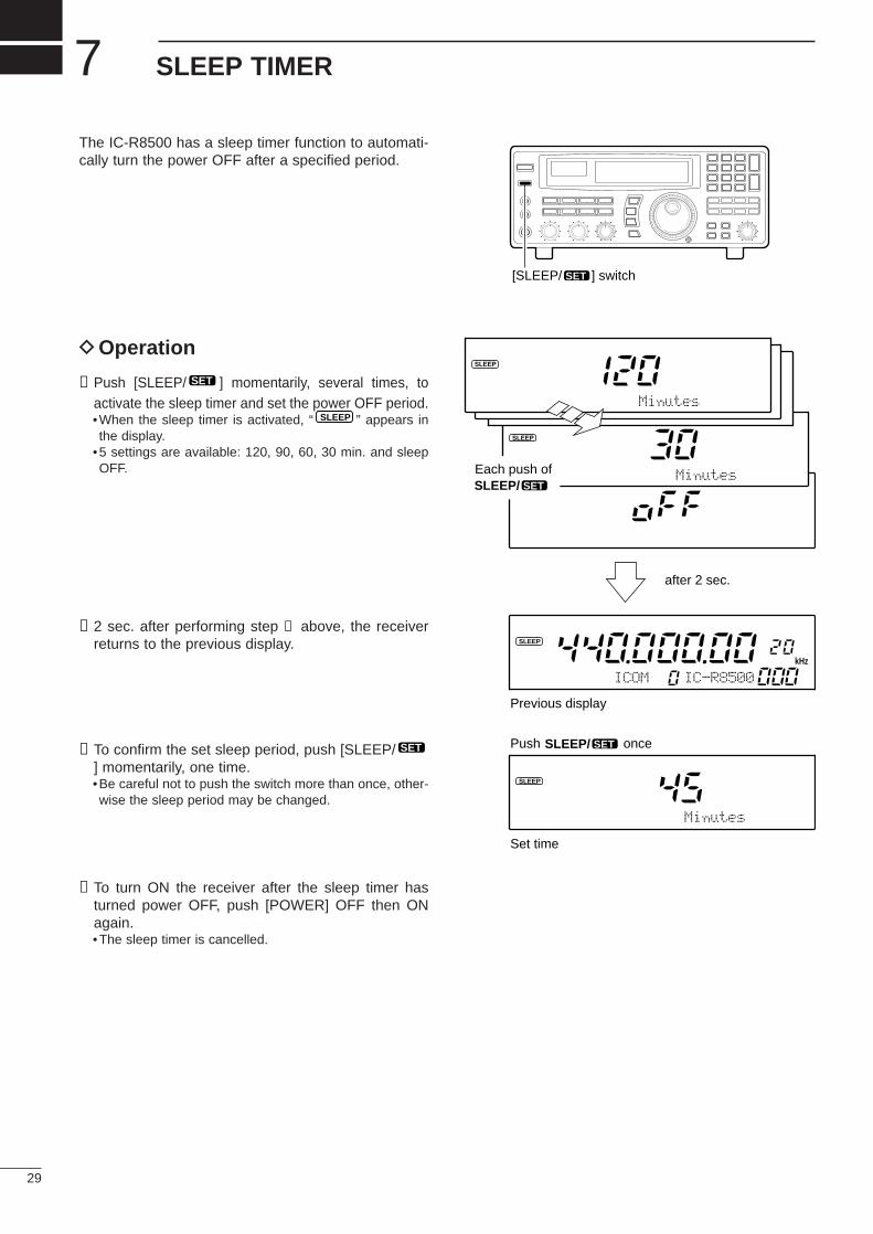
The IC-R8500 has a sleep timer function to automati-cally turn the power OFF after a specified period.
DOperation
➀Push [SLEEP/ ] momentarily, several times, toactivate the sleep timer and set the power OFF period.•When the sleep timer is activated, “ ” appears inthe display.
•5 settings are available: 120, 90, 60, 30 min. and sleepOFF.
➁2 sec. after performing step ➀ above, the receiverreturns to the previous display.
➂To confirm the set sleep period, push [SLEEP/] momentarily, one time.•Be careful not to push the switch more than once, other-wise the sleep period may be changed.
➃To turn ON the receiver after the sleep timer hasturned power OFF, push [POWER] OFF then ONagain.•The sleep timer is cancelled.
SET
SLEEP
SET
29
7 SLEEP TIMER
[SLEEP/ ] switchSET
SLEEP
IC-R8500ICOM
SLEEP
Minutes
MinutesEach push of SLEEP/ SET
SLEEP/ SET
after 2 sec.
Previous display
Set time
Push once
kHz
SLEEP
Minutes
SLEEP
30
8SET MODE
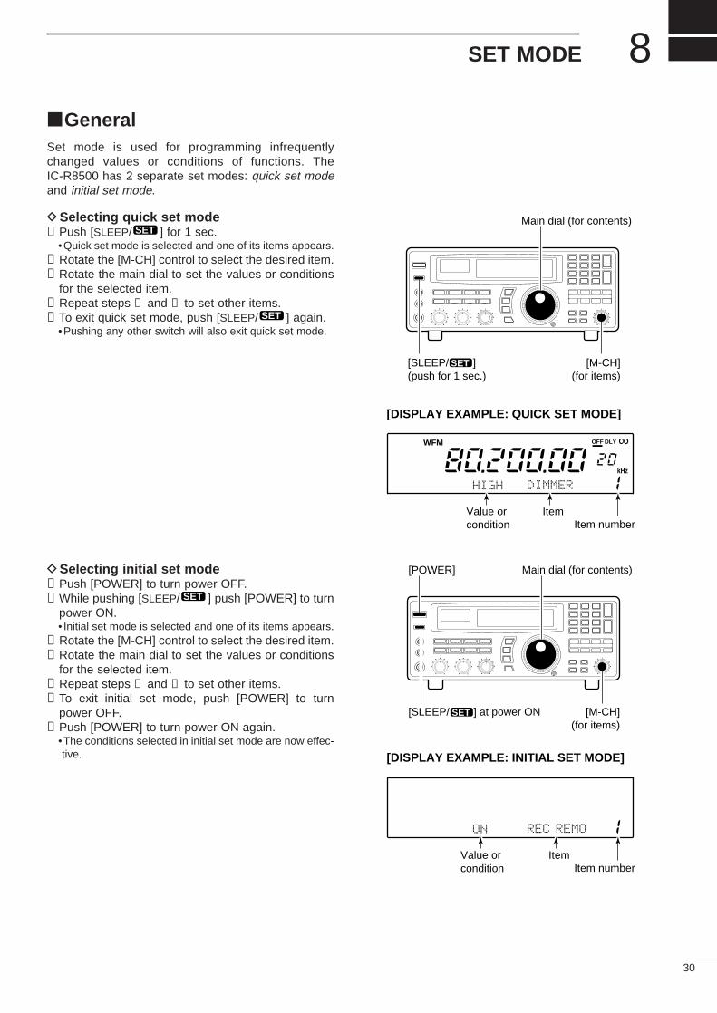
GeneralSet mode is used for programming infrequentlychanged values or conditions of functions. TheIC-R8500 has 2 separate set modes: quick set modeand initial set mode.
DSelecting quick set mode➀Push [SLEEP/ ] for 1 sec.
•Quick set mode is selected and one of its items appears.➁Rotate the [M-CH] control to select the desired item.➂Rotate the main dial to set the values or conditions
for the selected item.➃Repeat steps ➁ and ➂ to set other items.➄To exit quick set mode, push [SLEEP/ ] again.
•Pushing any other switch will also exit quick set mode.
DSelecting initial set mode➀Push [POWER] to turn power OFF.➁While pushing [SLEEP/ ] push [POWER] to turn
power ON.• Initial set mode is selected and one of its items appears.
➂Rotate the [M-CH] control to select the desired item.➃Rotate the main dial to set the values or conditions
for the selected item.➄Repeat steps ➂ and ➃ to set other items.➅To exit initial set mode, push [POWER] to turn
power OFF.➆Push [POWER] to turn power ON again.
•The conditions selected in initial set mode are now effec-tive.
SET
SET
SET
SCAN SET
Main dial (for contents)
[SLEEP/ ](push for 1 sec.)
[M-CH](for items)
SET
SCAN SET
[POWER] Main dial (for contents)
[SLEEP/ ] at power ON [M-CH](for items)
SET
WFM OFF
kHz
DLY ∞
HIGH DIMMER
Item numberItemValue or
condition
[DISPLAY EXAMPLE: QUICK SET MODE]
ON REC REMO
Item numberItemValue or
condition
[DISPLAY EXAMPLE: INITIAL SET MODE]
31
8 SET MODE
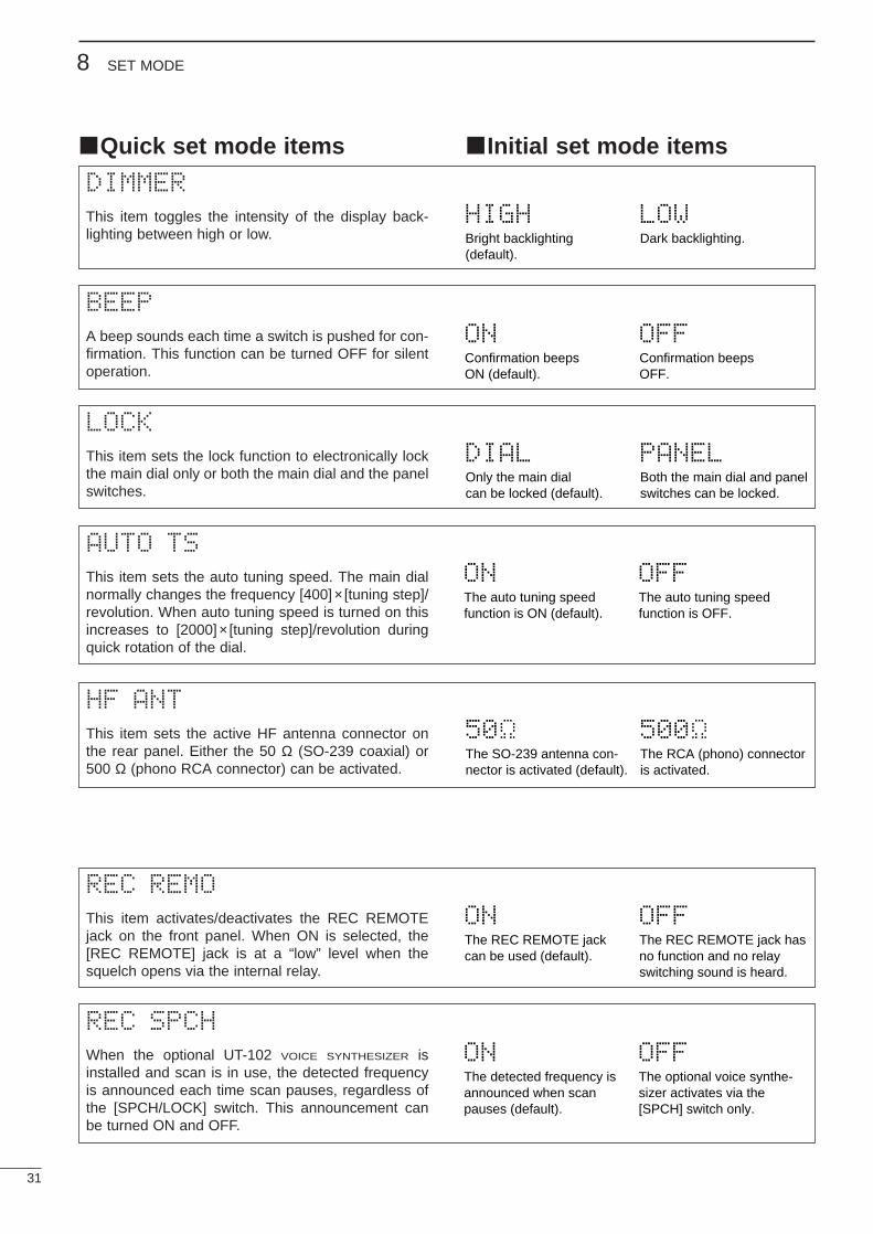
Quick set mode items Initial set mode items
DIMMER
This item toggles the intensity of the display back-lighting between high or low. Bright backlighting
(default).
HIGHDark backlighting.
LOW
BEEP
A beep sounds each time a switch is pushed for con-firmation. This function can be turned OFF for silentoperation.
Confirmation beepsON (default).
ONConfirmation beepsOFF.
OFF
LOCK
This item sets the lock function to electronically lockthe main dial only or both the main dial and the panelswitches.
Only the main dialcan be locked (default).
DIALBoth the main dial and panelswitches can be locked.
PANEL
AUTO TS
This item sets the auto tuning speed. The main dialnormally changes the frequency [400]× [tuning step]/revolution. When auto tuning speed is turned on thisincreases to [2000]× [tuning step]/revolution duringquick rotation of the dial.
The auto tuning speedfunction is ON (default).
ONThe auto tuning speedfunction is OFF.
OFF
HF ANT
This item sets the active HF antenna connector onthe rear panel. Either the 50 Ω (SO-239 coaxial) or500 Ω (phono RCA connector) can be activated.
The SO-239 antenna con-nector is activated (default).
50 The RCA (phono) connectoris activated.
500
REC REMO
This item activates/deactivates the REC REMOTEjack on the front panel. When ON is selected, the[REC REMOTE] jack is at a “low” level when thesquelch opens via the internal relay.
The REC REMOTE jackcan be used (default).
ON The REC REMOTE jack hasno function and no relayswitching sound is heard.
OFF
REC SPCH
When the optional UT-102 VOICE SYNTHESIZER isinstalled and scan is in use, the detected frequencyis announced each time scan pauses, regardless ofthe [SPCH/LOCK] switch. This announcement canbe turned ON and OFF.
The detected frequency isannounced when scanpauses (default).
ON The optional voice synthe-sizer activates via the[SPCH] switch only.
OFF
32
8SET MODE
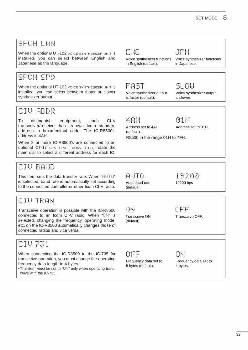
SPCH LAN
When the optional UT-102 VOICE SYNTHESIZER UNIT isinstalled, you can select between English andJapanese as the language.
Voice synthesizer functionsin English (default).
ENG Voice synthesizer functionsin Japanese.
JPN
SPCH SPD
When the optional UT-102 VOICE SYNTHESIZER UNIT isinstalled, you can select between faster or slowersynthesizer output.
Voice synthesizer outputis faster (default).
FASTVoice synthesizer outputis slower.
SLOW
CIV ADDR
To distinguish equipment, each CI-Vtransceiver/receiver has its own Icom standardaddress in hexadecimal code. The IC-R8500’saddress is 4AH.
When 2 or more IC-R8500’s are connected to anoptional CT-17 CI-V LEVEL CONVERTER, rotate themain dial to select a different address for each IC-
R8500 in the range 01H to 7FH.
Address set to 4AH(default).
4AHAddress set to 01H.
01H
CIV BAUD
This item sets the data transfer rate. When “AUTO”is selected, baud rate is automatically set accordingto the connected controller or other Icom CI-V radio.
Auto baud rate(default).
AUTO19200 bps
19200
CIV TRAN
Transceive operation is possible with the IC-R8500connected to an Icom CI-V radio. When “ON” isselected, changing the frequency, operating mode,etc. on the IC-R8500 automatically changes those ofconnected radios and vice versa.
Transceive ON(default).
ONTransceive OFF.
OFF
CIV 731
When connecting the IC-R8500 to the IC-735 fortransceive operation, you must change the operatingfrequency data length to 4 bytes.•This item must be set to “ON” only when operating trans-ceive with the IC-735.
Frequency data set to5 bytes (default).
OFFFrequency data set to4 bytes.
ON
33
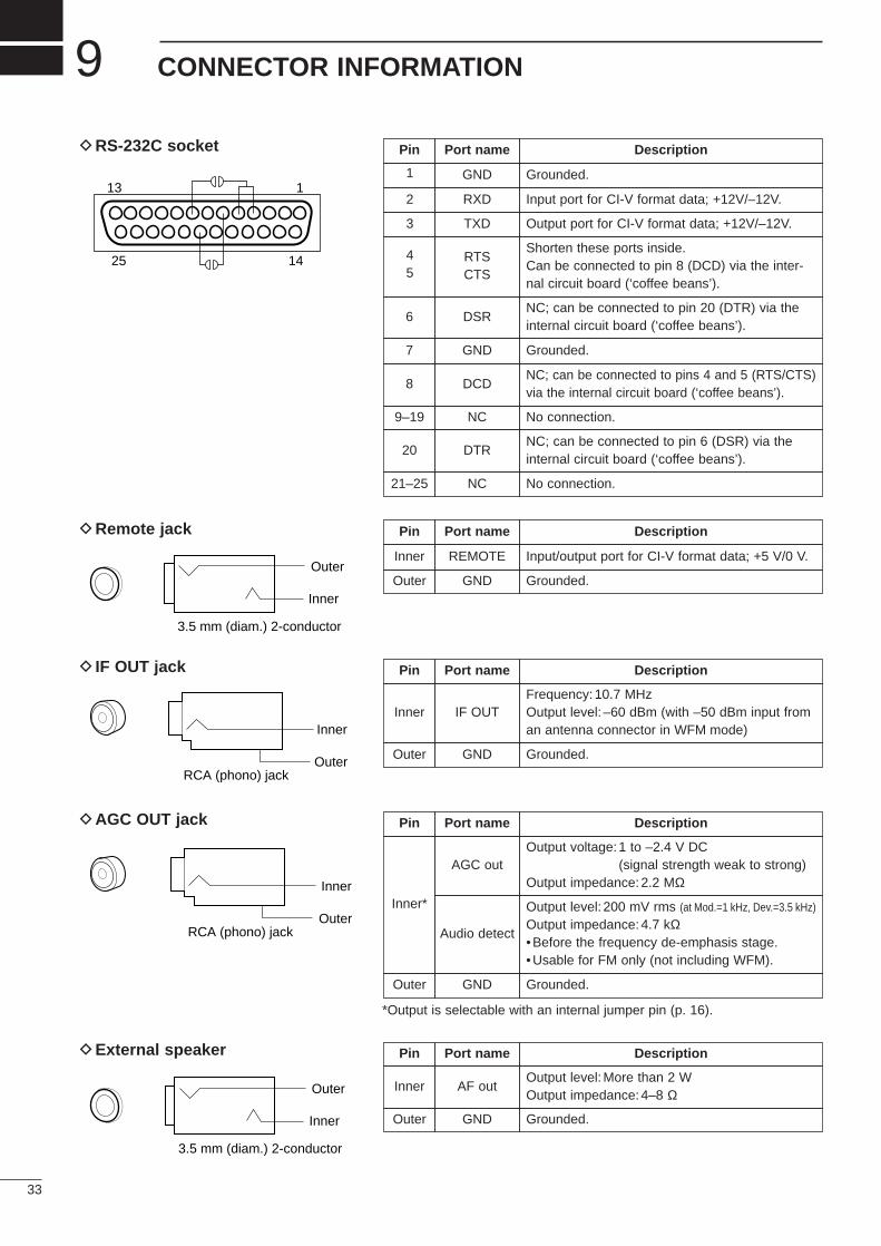
9 CONNECTOR INFORMATION
DRS-232C socket
DRemote jack
D IF OUT jack
DAGC OUT jack
DExternal speaker
Pin Port name Description
1 GND Grounded.
2 RXD Input port for CI-V format data; +12V/–12V.
3 TXD Output port for CI-V format data; +12V/–12V.
45
RTSCTS
Shorten these ports inside.Can be connected to pin 8 (DCD) via the inter-nal circuit board (‘coffee beans’).
6 DSRNC; can be connected to pin 20 (DTR) via theinternal circuit board (‘coffee beans’).
7 GND Grounded.
8 DCDNC; can be connected to pins 4 and 5 (RTS/CTS)via the internal circuit board (‘coffee beans’).
9–19 NC No connection.
20 DTRNC; can be connected to pin 6 (DSR) via theinternal circuit board (‘coffee beans’).
21–25 NC No connection.
13 1
25 14
Pin Port name Description
Inner REMOTE Input/output port for CI-V format data; +5 V/0 V.
Outer GND Grounded.
Pin Port name Description
Inner IF OUTFrequency:10.7 MHzOutput level: –60 dBm (with –50 dBm input froman antenna connector in WFM mode)
Outer GND Grounded.
*Output is selectable with an internal jumper pin (p. 16).
Pin Port name Description
Inner*
AGC outOutput voltage:1 to –2.4 V DC
(signal strength weak to strong)Output impedance:2.2 MΩ
Audio detect
Output level: 200 mV rms (at Mod.=1 kHz, Dev.=3.5 kHz)
Output impedance:4.7 kΩ•Before the frequency de-emphasis stage.•Usable for FM only (not including WFM).
Outer GND Grounded.
Pin Port name Description
Inner AF outOutput level:More than 2 WOutput impedance:4–8 Ω
Outer GND Grounded.
3.5 mm (diam.) 2-conductor
Outer
Inner
RCA (phono) jack
Inner
Outer
RCA (phono) jack
Inner
Outer
3.5 mm (diam.) 2-conductor
Outer
Inner
34
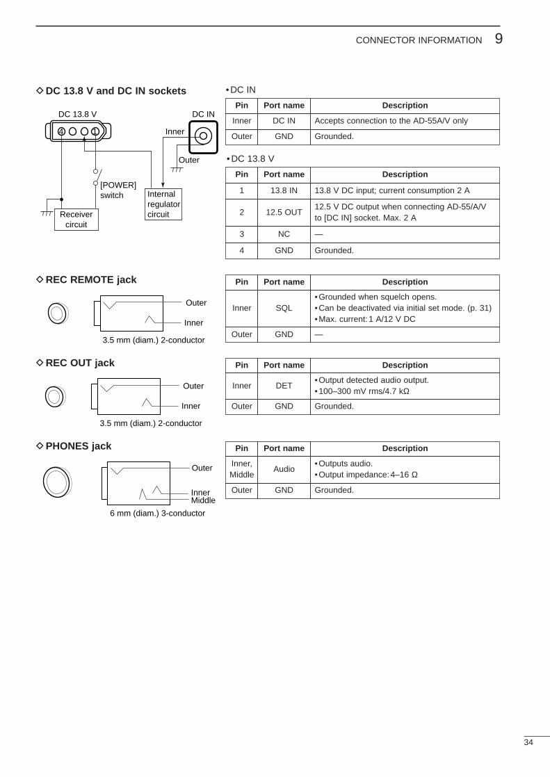
9CONNECTOR INFORMATION
DDC 13.8 V and DC IN sockets
DREC REMOTE jack
• DC IN
• DC 13.8 V
DC 13.8 V
Inner
Outer
[POWER]switch
Receivercircuit
Internalregulatorcircuit
DC IN
4 1
Pin Port name Description
Inner DC IN Accepts connection to the AD-55A/V only
Outer GND Grounded.
Pin Port name Description
1 13.8 IN 13.8 V DC input; current consumption 2 A
2 12.5 OUT12.5 V DC output when connecting AD-55/A/Vto [DC IN] socket. Max. 2 A
3 NC —
4 GND Grounded.
Pin Port name Description
Inner SQL•Grounded when squelch opens.•Can be deactivated via initial set mode. (p. 31)•Max. current: 1 A/12 V DC
Outer GND —
Pin Port name Description
Inner DET•Output detected audio output.• 100–300 mV rms/4.7 kΩ
Outer GND Grounded.
Pin Port name Description
Inner, Middle
Audio•Outputs audio.•Output impedance:4–16 Ω
Outer GND Grounded.
3.5 mm (diam.) 2-conductor
Outer
Inner
DREC OUT jack
3.5 mm (diam.) 2-conductor
Outer
Inner
DPHONES jack
6 mm (diam.) 3-conductor
MiddleInner
Outer
CONTROL COMMANDS10
35
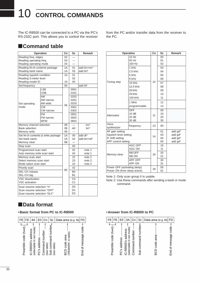
The IC-R8500 can be connected to a PC via the PC’sRS-232C port. This allows you to control the receiver
from the PC and/or transfer data from the receiver tothe PC.
Operation Cn Sc RemarkReading freq. edgesReading operating freq.Reading operating mode
020304
———
Reading M-ch contents packageReading bank name
1A1A
0103
add bn+mc*add bn*
Reading squelch conditionReading S-meter levelReading model ID
15
19
010200
05 add fd*
Set operatingmode
06
0001010102020201020303010302050105020601
Memory channel selectionBank selectionMemory write
080809
—A0—
mc*bn*
Set M-ch contents & write packageSet bank nameMemory clear
1A1A0B
0002—
add dt*add bn+nd*
Stop scan
0E
00
Programmed scan startAuto memory write scan start
0204
note 1note 1
Memory scan startSelect memory scan startMode select scan start
222324
note 2note 2note 2
Priority scan 42
SEL-CH releaseSEL-CH tag
B0B1
VSC deactivationVSC activation
C0C1
Scan resume selection “∞”Scan resume selection “OFF”Scan resume selection “DLY”
D0D1D3
LSBUSBAMAM narrowAM wideCWCW narrowFMFM narrowWFM
Operation Cn Sc Remark
Tuning step 10
000102
03040506
0708091011
1213
11
00102030
13 00
01030405
add gd*add gd*add gd*add gd*
Memory clear 16
1011
2021
3031
Power OFF (activating sleep)Power ON (from sleep active)
180001
1 MHzprogrammable
OFF10 dB20 dB30 dB
frequency
10 Hz50 Hz100 Hz
1 kHz2.5 kHz5 kHz9 kHz
10 kHz12.5 kHz20 kHz25 kHz100 kHz
Voicesynthesizer
Attenuator
AF gain settingSquelch level settingIF shift settingAPF control setting
14
AGC OFFAGC ON
APF OFFAPF ON
NB OFFNB ON
Note 1: Only scan group 0 is usable.Note 2: Use these commands after sending a bank or mode
command.
Set frequency
Command table
FE FE 4A E0 Cn Sc Data area (e.g. fd) FD
Pre
ambl
e co
de (f
ixed
)
PC
’s a
ddre
ss
IC-R
8500
’s a
ddre
ss(s
elec
tabl
e in
set
mod
e)
Com
man
d nu
mbe
r(s
ee ta
ble)
Sub
com
man
d nu
mbe
r(s
ee ta
ble)
BC
D c
ode
area
(‘RE
MA
RK
’ in
tabl
e)
End
of m
essa
ge c
ode
FE FE E0 4A Cn Sc Data area (e.g. fd) FD
Pre
ambl
e co
de (f
ixed
)
PC
’s a
ddre
ss
IC-R
8500
’s a
ddre
ss(s
elec
tabl
e in
set
mod
e)
Com
man
d nu
mbe
r
Sub
com
man
d nu
mbe
r
BC
D c
ode
area
End
of m
essa
ge c
ode
Data format• Basic format from PC to IC-R8500 • Answer from IC-R8500 to PC
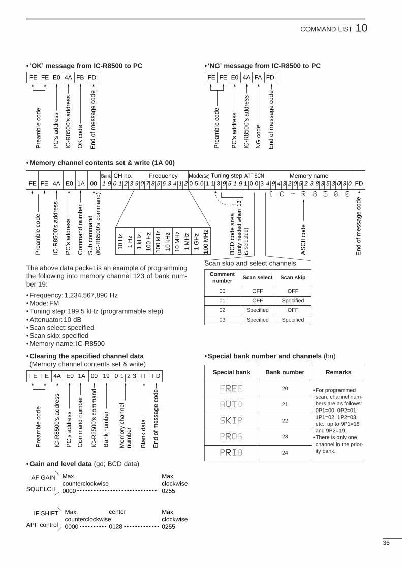
36
10COMMAND LIST
• ‘OK’ message from IC-R8500 to PC • ‘NG’ message from IC-R8500 to PC
• Memory channel contents set & write (1A 00)
The above data packet is an example of programmingthe following into memory channel 123 of bank num-ber 19:
• Frequency: 1,234,567,890 Hz• Mode: FM• Tuning step:199.5 kHz (programmable step)• Attenuator: 10 dB• Scan select: specified• Scan skip: specified• Memory name: IC-R8500
Scan skip and select channels
FE FE E0 4A FB FD
Pre
ambl
e co
de
PC
’s a
ddre
ss
IC-R
8500
’s a
ddre
ss
OK
cod
e
End
of m
essa
ge c
ode
FE FE 4A E0 1A 00 1 9 0 1 2 3 9 0 7 8 5 6 3 4 1 2 0 5 0 1 1 3 9 5 1 9 1 0 0 3 4 9 4 3 2 0 5 2 3 8 3 5 3 0 3 0 FDMemory nameTuning stepMode(Sc)FrequencyCH no.Bank SCNATT
Pre
ambl
e co
de
IC-R
8500
’s a
ddre
ss
PC
’s a
ddre
ss
Com
man
d nu
mbe
r
Sub
com
man
d(I
C-R
8500
’s c
omm
and)
10 H
z
1 H
z
1 kH
z
100
Hz
100
kHz
10 k
Hz
10 M
Hz
1 M
Hz
1 G
Hz
100
MH
z
End
of m
essa
ge c
ode
AS
CII
code
BC
D c
ode
area
(onl
y ne
eded
whe
n ‘1
3’is
sel
ecte
d)
I C - R 8 5 0 0
FE FE E0 4A FA FD
Pre
ambl
e co
de
PC
’s a
ddre
ss
IC-R
8500
’s a
ddre
ss
NG
cod
e
End
of m
essa
ge c
ode
Commentnumber
Scan select Scan skip
00 OFF OFF
01 OFF Specified
02 Specified OFF
03 Specified Specified
•Clearing the specified channel data(Memory channel contents set & write)
•Special bank number and channels (bn)
FE FE 4A E0 1A 00 19 0 1 2 3 FF FD
Pre
ambl
e co
de
PC
’s a
ddre
ss
IC-R
8500
’s a
ddre
ss
Com
man
d nu
mbe
r
End
of m
essa
ge c
ode
Bla
nk d
ata
Mem
ory
chan
nel
num
ber
IC-R
8500
’s c
omm
and
Ban
k nu
mbe
r
Special bank Bank number
FREE 20
AUTO 21
SKIP 22
PROG 23
PRIO 24
Remarks
•For programmedscan, channel num-bers are as follows:0P1=00, 0P2=01,1P1=02, 1P2=03,etc., up to 9P1=18and 9P2=19.
•There is only onechannel in the prior-ity bank.
•Gain and level data (gd; BCD data)
AF GAIN
SQUELCH
Max.counterclockwise0000
Max.clockwise0255
IF SHIFT
APF control
Max.counterclockwise0000
Max.clockwise0255
center
0128
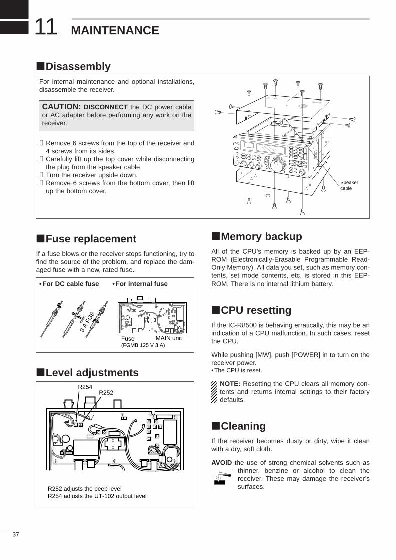
Disassembly
Fuse replacementIf a fuse blows or the receiver stops functioning, try tofind the source of the problem, and replace the dam-aged fuse with a new, rated fuse.
Level adjustments
3 A
FGB
• For DC cable fuse • For internal fuse
37
11 MAINTENANCE
Memory backupAll of the CPU’s memory is backed up by an EEP-ROM (Electronically-Erasable Programmable Read-Only Memory). All data you set, such as memory con-tents, set mode contents, etc. is stored in this EEP-ROM. There is no internal lithium battery.
CPU resettingIf the IC-R8500 is behaving erratically, this may be anindication of a CPU malfunction. In such cases, resetthe CPU.
While pushing [MW], push [POWER] in to turn on thereceiver power.•The CPU is reset.
NOTE: Resetting the CPU clears all memory con-tents and returns internal settings to their factorydefaults.
CleaningIf the receiver becomes dusty or dirty, wipe it cleanwith a dry, soft cloth.
AVOID the use of strong chemical solvents such asthinner, benzine or alcohol to clean thereceiver. These may damage the receiver’ssurfaces.
For internal maintenance and optional installations,disassemble the receiver.
➀Remove 6 screws from the top of the receiver and4 screws from its sides.
➁Carefully lift up the top cover while disconnectingthe plug from the speaker cable.
➂Turn the receiver upside down.➃Remove 6 screws from the bottom cover, then lift
up the bottom cover.Speakercable
MAIN unitFuse(FGMB 125 V 3 A)
CAUTION: DISCONNECT the DC power cableor AC adapter before performing any work on thereceiver.
R254R252
R252 adjusts the beep levelR254 adjusts the UT-102 output level
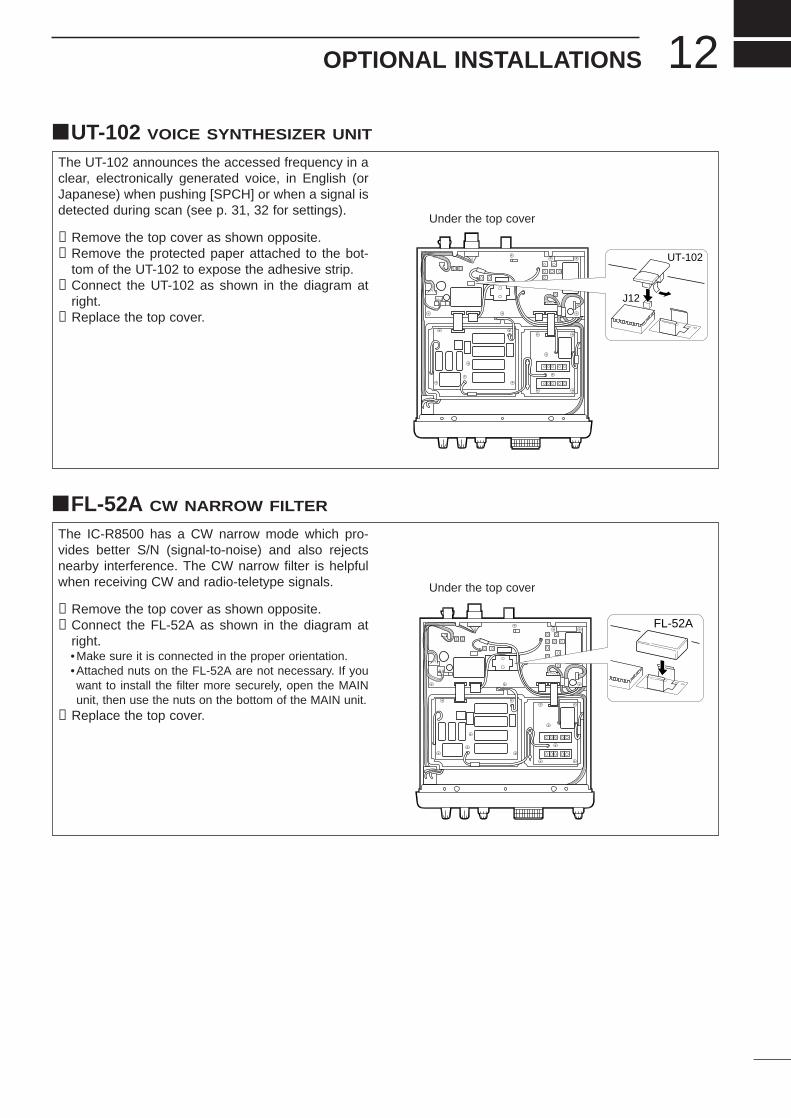
12OPTIONAL INSTALLATIONS
UT-102 VOICE SYNTHESIZER UNIT
The UT-102 announces the accessed frequency in aclear, electronically generated voice, in English (orJapanese) when pushing [SPCH] or when a signal isdetected during scan (see p. 31, 32 for settings).
➀Remove the top cover as shown opposite.➁Remove the protected paper attached to the bot-
tom of the UT-102 to expose the adhesive strip.➂Connect the UT-102 as shown in the diagram at
right.➃Replace the top cover.
J12
UT-102
FL-52A CW NARROW FILTER
The IC-R8500 has a CW narrow mode which pro-vides better S/N (signal-to-noise) and also rejectsnearby interference. The CW narrow filter is helpfulwhen receiving CW and radio-teletype signals.
➀Remove the top cover as shown opposite.➁Connect the FL-52A as shown in the diagram at
right.•Make sure it is connected in the proper orientation.•Attached nuts on the FL-52A are not necessary. If youwant to install the filter more securely, open the MAINunit, then use the nuts on the bottom of the MAIN unit.
➂Replace the top cover.
FL-52A
Under the top cover
Under the top cover
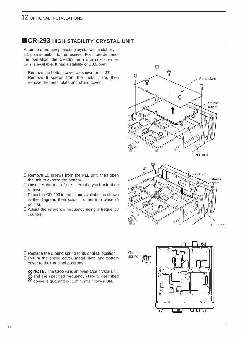
39
12 OPTIONAL INSTALLATIONS
CR-293 HIGH STABILITY CRYSTAL UNIT
A temperature-compensating crystal with a stability of±3 ppm is built-in to the receiver. For more demand-ing operation, the CR-293 HIGH STABILITY CRYSTAL
UNIT is available. It has a stability of ±0.5 ppm.
➀Remove the bottom cover as shown on p. 37.➁Remove 6 screws from the metal plate, then
remove the metal plate and shield cover.
➂Remove 10 screws from the PLL unit, then openthe unit to expose the bottom.
➃Unsolder the feet of the internal crystal unit, thenremove it.
➄Place the CR-293 in the space available as shownin the diagram, then solder its feet into place (6points).
➅Adjust the reference frequency using a frequencycounter.
➆Replace the ground spring to its original position.➇Return the shield cover, metal plate and bottom
cover to their original positions.
NOTE: The CR-293 is an oven-type crystal unit,and the specified frequency stability describedabove is guaranteed 1 min. after power ON.
Shieldcover
PLL unit
Groundspring
PLL unit
CR-293Internalcrystalunit
Metal plate
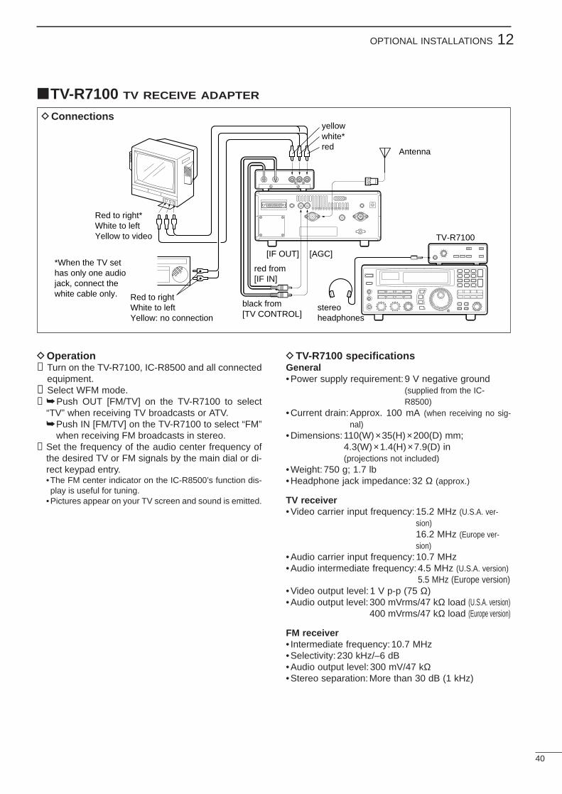
40
12OPTIONAL INSTALLATIONS
TV-R7100 TV RECEIVE ADAPTER
DConnections
DOperation➀Turn on the TV-R7100, IC-R8500 and all connected
equipment.➁Select WFM mode.➂ Push OUT [FM/TV] on the TV-R7100 to select
“TV” when receiving TV broadcasts or ATV.Push IN [FM/TV] on the TV-R7100 to select “FM”
when receiving FM broadcasts in stereo.➃Set the frequency of the audio center frequency of
the desired TV or FM signals by the main dial or di-rect keypad entry.•The FM center indicator on the IC-R8500’s function dis-play is useful for tuning.
•Pictures appear on your TV screen and sound is emitted.
DTV-R7100 specificationsGeneral• Power supply requirement:9 V negative ground
(supplied from the IC-R8500)
• Current drain:Approx. 100 mA (when receiving no sig-nal)
• Dimensions:110(W)×35(H)×200(D) mm;4.3(W) ×1.4(H)×7.9(D) in(projections not included)
• Weight: 750 g; 1.7 lb• Headphone jack impedance:32 Ω (approx.)
TV receiver• Video carrier input frequency:15.2 MHz (U.S.A. ver-
sion)16.2 MHz (Europe ver-sion)
• Audio carrier input frequency:10.7 MHz• Audio intermediate frequency:4.5 MHz (U.S.A. version)
5.5 MHz (Europe version)• Video output level: 1 V p-p (75 Ω)• Audio output level: 300 mVrms/47 kΩ load (U.S.A. version)
400 mVrms/47 kΩ load (Europe version)
FM receiver• Intermediate frequency: 10.7 MHz• Selectivity: 230 kHz/–6 dB• Audio output level: 300 mV/47 kΩ• Stereo separation: More than 30 dB (1 kHz)
TV-R7100
stereoheadphones
Antenna
yellowwhite*red
[IF OUT]
red from[IF IN]
black from[TV CONTROL]
Red to rightWhite to leftYellow: no connection
Red to right*White to leftYellow to video
*When the TV sethas only one audiojack, connect thewhite cable only.
[AGC]
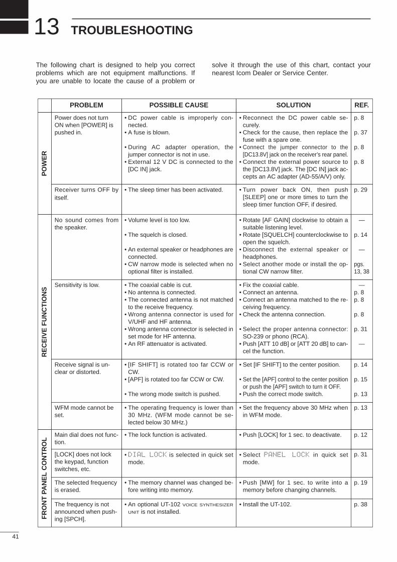
41
13 TROUBLESHOOTING
The following chart is designed to help you correctproblems which are not equipment malfunctions. Ifyou are unable to locate the cause of a problem or
solve it through the use of this chart, contact yournearest Icom Dealer or Service Center.
POSSIBLE CAUSE SOLUTION REF.
PO
WE
R
• DC power cable is improperly con-nected.
• A fuse is blown.
• During AC adapter operation, thejumper connector is not in use.
• External 12 V DC is connected to the[DC IN] jack.
• Reconnect the DC power cable se-curely.
• Check for the cause, then replace thefuse with a spare one.
• Connect the jumper connector to the[DC13.8V] jack on the receiver’s rear panel.
• Connect the external power source tothe [DC13.8V] jack. The [DC IN] jack ac-cepts an AC adapter (AD-55/A/V) only.
p. 8
p. 37
p. 8
p. 8
RE
CE
IVE
FU
NC
TIO
NS
• Volume level is too low.
• The squelch is closed.
• An external speaker or headphones areconnected.
• CW narrow mode is selected when nooptional filter is installed.
• Rotate [AF GAIN] clockwise to obtain asuitable listening level.
• Rotate [SQUELCH] counterclockwise toopen the squelch.
• Disconnect the external speaker orheadphones.
• Select another mode or install the op-tional CW narrow filter.
—
p. 14
—
pgs.13, 38
• The coaxial cable is cut.• No antenna is connected.• The connected antenna is not matched
to the receive frequency.• Wrong antenna connector is used for
V/UHF and HF antenna.• Wrong antenna connector is selected in
set mode for HF antenna.• An RF attenuator is activated.
• Fix the coaxial cable.• Connect an antenna.• Connect an antenna matched to the re-
ceiving frequency.• Check the antenna connection.
• Select the proper antenna connector:SO-239 or phono (RCA).
• Push [ATT 10 dB] or [ATT 20 dB] to can-cel the function.
—p. 8p. 8
p. 8
p. 31
—
• [IF SHIFT] is rotated too far CCW orCW.
• [APF] is rotated too far CCW or CW.
• The wrong mode switch is pushed.
• Set [IF SHIFT] to the center position.
• Set the [APF] control to the center positionor push the [APF] switch to turn it OFF.
• Push the correct mode switch.
p. 14
p. 15
p. 13
• The operating frequency is lower than30 MHz. (WFM mode cannot be se-lected below 30 MHz.)
• Set the frequency above 30 MHz whenin WFM mode.
p. 13
FR
ON
T P
AN
EL
CO
NT
RO
L
• The lock function is activated. • Push [LOCK] for 1 sec. to deactivate. p. 12
• DIAL LOCK is selected in quick setmode.
• Select PANEL LOCK in quick setmode.
p. 31
PROBLEM
Power does not turnON when [POWER] ispushed in.
No sound comes fromthe speaker.
Sensitivity is low.
Receive signal is un-clear or distorted.
WFM mode cannot beset.
Main dial does not func-tion.
[LOCK] does not lockthe keypad, functionswitches, etc.
• The memory channel was changed be-fore writing into memory.
• Push [MW] for 1 sec. to write into amemory before changing channels.
p. 19The selected frequencyis erased.
• An optional UT-102 VOICE SYNTHESIZER
UNIT is not installed.• Install the UT-102. p. 38The frequency is not
announced when push-ing [SPCH].
• The sleep timer has been activated. • Turn power back ON, then push[SLEEP] one or more times to turn thesleep timer function OFF, if desired.
p. 29Receiver turns OFF byitself.
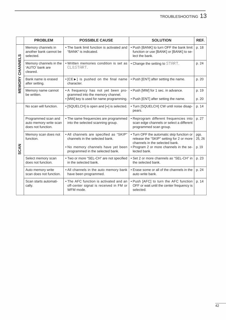
42
13TROUBLESHOOTINGM
EM
OR
Y C
HA
NN
ELS
• The bank limit function is activated and“BANK” is indicated.
• Push [BANK] to turn OFF the bank limitfunction or use [BANK] or [BANK] to se-lect the bank.
p. 18Memory channels inanother bank cannot beselected.
SC
AN
• [SQUELCH] is open and [∞] is selected. • Turn [SQUELCH] CW until noise disap-pears.
p. 14No scan will function.
• The same frequencies are programmedinto the selected scanning group.
• Reprogram different frequencies intoscan edge channels or select a differentprogrammed scan group.
p. 27Programmed scan andauto memory write scandoes not function.
• All channels are specified as “SKIP”channels in the selected bank.
• No memory channels have yet beenprogrammed in the selected bank.
• Turn OFF the automatic skip function orrelease the “SKIP” setting for 2 or morechannels in the selected bank.
• Program 2 or more channels in the se-lected bank.
pgs.25, 26
p. 19
Memory scan does notfunction.
• Two or more “SEL-CH” are not specifiedin the selected bank.
• Set 2 or more channels as “SEL-CH” inthe selected bank.
p. 23Select memory scandoes not function.
• All channels in the auto memory bankhave been programmed.
• Erase some or all of the channels in theauto write bank.
p. 24Auto memory writescan does not function.
• The AFC function is activated and anoff-center signal is received in FM orWFM mode.
• Push [AFC] to turn the AFC functionOFF or wait until the center frequency isselected.
p. 14Scan starts automati-cally.
• Written memories condition is set asCL&START.
• Change the setting to START. p. 24Memory channels in the‘AUTO’ bank arecleared.
• [CEs] is pushed on the final namecharacter.
• Push [ENT] after setting the name. p. 20Bank name is erasedafter setting.
• A frequency has not yet been pro-grammed into the memory channel.
• [MW] key is used for name programming.
• Push [MW] for 1 sec. in advance.
• Push [ENT] after setting the name.
p. 19
p. 20
Memory name cannotbe written.
POSSIBLE CAUSE SOLUTION REF.PROBLEM
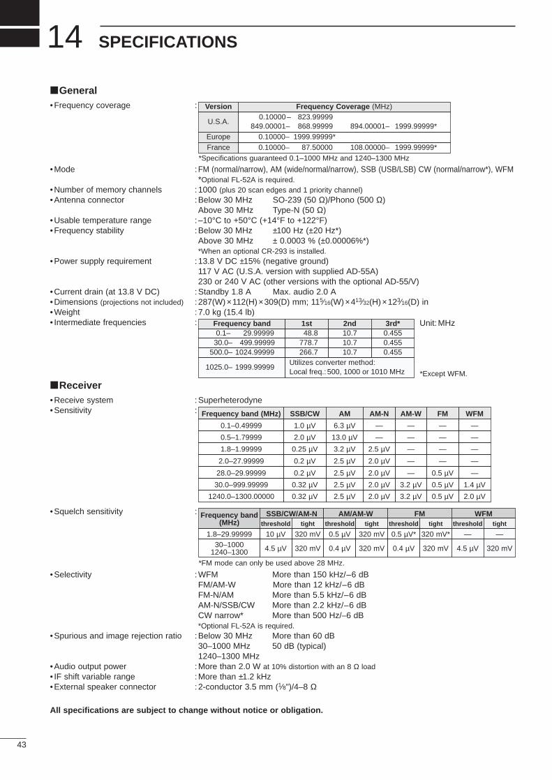
General•Frequency coverage :
•Mode : FM (normal/narrow), AM (wide/normal/narrow), SSB (USB/LSB) CW (normal/narrow*), WFM*Optional FL-52A is required.
•Number of memory channels : 1000 (plus 20 scan edges and 1 priority channel)•Antenna connector :Below 30 MHz SO-239 (50 Ω)/Phono (500 Ω)
Above 30 MHz Type-N (50 Ω)•Usable temperature range :–10°C to +50°C (+14°F to +122°F)•Frequency stability :Below 30 MHz ±100 Hz (±20 Hz*)
Above 30 MHz ± 0.0003 % (±0.00006%*)*When an optional CR-293 is installed.
•Power supply requirement :13.8 V DC ±15% (negative ground)117 V AC (U.S.A. version with supplied AD-55A)230 or 240 V AC (other versions with the optional AD-55/V)
•Current drain (at 13.8 V DC) :Standby 1.8 A Max. audio 2.0 A•Dimensions (projections not included) : 287(W) ×112(H)×309(D) mm; 115⁄16(W) ×413⁄32(H)×123⁄16(D) in•Weight : 7.0 kg (15.4 lb)• Intermediate frequencies :
Receiver•Receive system :Superheterodyne•Sensitivity :
•Squelch sensitivity :
•Selectivity :WFM More than 150 kHz/–6 dBFM/AM-W More than 12 kHz/–6 dBFM-N/AM More than 5.5 kHz/–6 dBAM-N/SSB/CW More than 2.2 kHz/–6 dBCW narrow* More than 500 Hz/–6 dB*Optional FL-52A is required.
•Spurious and image rejection ratio :Below 30 MHz More than 60 dB30–1000 MHz 50 dB (typical)1240–1300 MHz
•Audio output power :More than 2.0 W at 10% distortion with an 8 Ω load• IF shift variable range :More than ±1.2 kHz•External speaker connector : 2-conductor 3.5 mm (1⁄8")/4–8 Ω
All specifications are subject to change without notice or obligation.
43
14 SPECIFICATIONS
Version Frequency Coverage (MHz)
U.S.A.0.10000– 823.99999
849.00001– 868.99999 894.00001– 1999.99999*Europe 0.10000– 1999.99999*France 0.10000– 87.50000 108.00000– 1999.99999*
Frequency band 1st 2nd 3rd*0.1– 29.99999 48.8 10.7 0.455
30.0– 499.99999 778.7 10.7 0.455500.0– 1024.99999 266.7 10.7 0.455
Frequency band (MHz) SSB/CW
0.1–0.49999 1.0 µV 6.3 µV — — — —
0.5–1.79999 2.0 µV 13.0 µV — — — —
1.8–1.99999 0.25 µV 3.2 µV 2.5 µV — — —
2.0–27.99999 0.2 µV 2.5 µV 2.0 µV — — —
28.0–29.99999 0.2 µV 2.5 µV 2.0 µV — 0.5 µV —
30.0–999.99999 0.32 µV 2.5 µV 2.0 µV 3.2 µV 0.5 µV 1.4 µV
1240.0–1300.00000 0.32 µV 2.5 µV 2.0 µV 3.2 µV 0.5 µV 2.0 µV
*Specifications guaranteed 0.1–1000 MHz and 1240–1300 MHz
1025.0– 1999.99999Utilizes converter method:Local freq.: 500, 1000 or 1010 MHz
Frequency band(MHz)
SSB/CW/AM-Nthreshold tight threshold tight threshold tight
1.8–29.99999 10 µV 320 mV 0.5 µV 320 mV 0.5 µV* 320 mV*30–1000
1240–1300 4.5 µV 320 mV 0.4 µV 320 mV 0.4 µV 320 mV
FMAM/AM-W WFMthreshold tight
— —
4.5 µV 320 mV
WFMFMAM-WAM-NAM
*FM mode can only be used above 28 MHz.
Unit:MHz
*Except WFM.
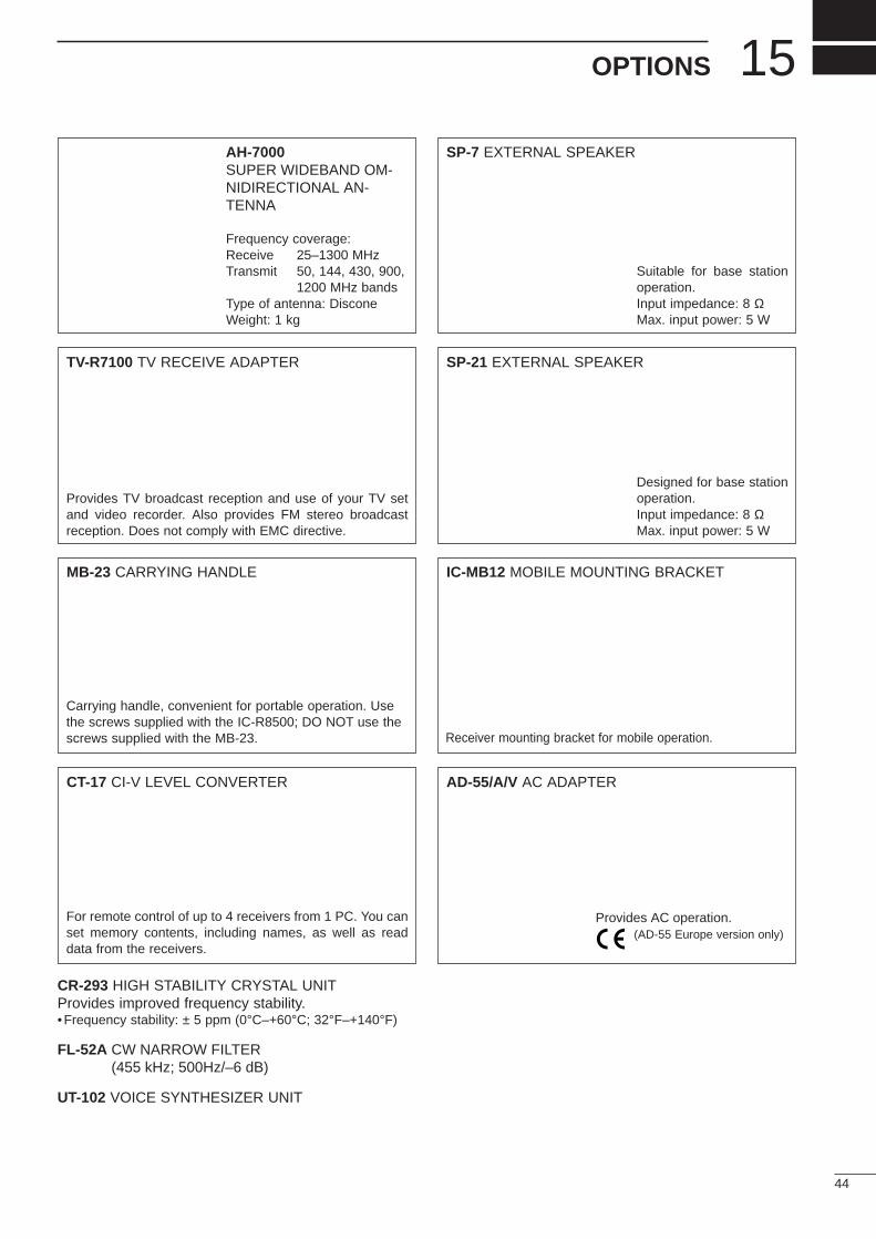
44
15OPTIONS
AH-7000SUPER WIDEBAND OM-NIDIRECTIONAL AN-TENNA
SP-7 EXTERNAL SPEAKER
TV-R7100 TV RECEIVE ADAPTER SP-21 EXTERNAL SPEAKER
MB-23 CARRYING HANDLE IC-MB12 MOBILE MOUNTING BRACKET
CT-17 CI-V LEVEL CONVERTER AD-55/A/V AC ADAPTER
CR-293 HIGH STABILITY CRYSTAL UNITProvides improved frequency stability.•Frequency stability: ± 5 ppm (0°C–+60°C; 32°F–+140°F)
FL-52A CW NARROW FILTER(455 kHz; 500Hz/–6 dB)
UT-102 VOICE SYNTHESIZER UNIT
Frequency coverage:Receive 25–1300 MHzTransmit 50, 144, 430, 900,
1200 MHz bandsType of antenna: DisconeWeight: 1 kg
Provides TV broadcast reception and use of your TV setand video recorder. Also provides FM stereo broadcastreception. Does not comply with EMC directive.
Carrying handle, convenient for portable operation. Usethe screws supplied with the IC-R8500; DO NOT use thescrews supplied with the MB-23.
For remote control of up to 4 receivers from 1 PC. You canset memory contents, including names, as well as readdata from the receivers.
Suitable for base stationoperation.Input impedance: 8 ΩMax. input power: 5 W
Designed for base stationoperation.Input impedance: 8 ΩMax. input power: 5 W
Receiver mounting bracket for mobile operation.
Provides AC operation.(AD-55 Europe version only)
A-5395Y-1EX-➀Printed in JapanCopyright©1996 by Icom Inc. 1-1-32 Kamiminami, Hirano-ku, Osaka 547-0003 Japan
Count on us!


