Page 1
Hunan Famous Trademark
Vice president company
HONOR
Zhuzhou Huarui Precision Cutting Tools Co.,Ltd. is a high and new tech enterprise engaged in the
production of cemented carbide cutting tools for CNC machinery, the municipal supporting institution of
Zhuzhou Carbide Precision Cutting tool Engineering Technology Research Center. Also the production line has
been named key project of “Manufacture makes Hunan stronger”. In the market, its “Hardstone” Brand
products with excellent properties have been widely used in industries of automobiles, aviation & aerospace,
rail traffic, heavy equipment, mold manufacture, power equipment,etc. and have been accepted by customers.
Therefore they are selling to various overseas markets.
With its good development prospects, the company has won great favor from various investors. The well-
known domestic equity investment funds invested a large sum of money for company in 2011, 2015 and 2017,
which has speed-ed up the introduction of high-tech manufacturing equipments and quality test instruments.
Therefore, the product quality has climbed one storey higher & reached the first- class in Asia.
The company has in its possession a strong technical strength & has forged a top domestic specialized &
high-level R & D team of old, middle-aged & young professional personnel. They included experts enjoying
special allowance of the state council & introduced outstanding CNC talents. The company has its own R&D
Center consisting of material research, products design, mould design & manufacture, cutting experiments &
technical application service, etc. ensuring the provision to customers of the best solutions to products &
technical service. At present, the company has 22 nationally authorized patents.
The company has its quality control system covering the whole processes with independent intellectual
property rights to guarantee the stability and consistency of its products. The company was awarded
ISO9001:2000 quality management system certificate,and passed ISO9001:2015 quality standard system
certificate in 2014.
The company has experienced sales engineers and technical application engineers, and has set up its
product and technical service branched in China’s major industrial cities to provide the most professional
and efficient service.
COMPANY PROFILE
Page 2
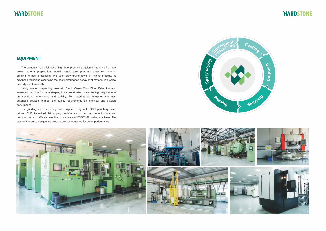
The company has a full set of high-level producing equipment ranging from raw
power material preparation, mould manufacture, pressing, pressure sintering,
grinding to post processing. We use spray drying tower in mixing process. Its
advanced technique ascertains the best performance behavior of material in physical
property and formability.
Using powder compacting press with Electro-Servo Motor Direct Drive, the most
advanced machine for press shaping in the world, which meet the high requirements
on precision, performance and stability. For sintering, we equipped the most
advanced devices to meet the quality requirements on chemical and physical
performance.
For grinding and machining, we equipped Fully auto CNC periphery insert
grinder, CNC two-wheel flat lapping machine etc. to ensure product shape and
precision demand. We also use the most advanced PVD/CVD coating machines. The
state-of-the-art sub-sequence process devices equipped for better performance.
EQUIPMENT gni
yrd
yra
pS
Grin
din
g
Coating
tneuqesbuS
gnissecorp
Page 3
Drilling Insert
General Technical Data
目 录
Turning Insert
A1 Negative Inserts
For Stainless Steel
The Explanation Of Chip-breaker A-02 — 05
The Explanation Of Grade A-06 — 07
The Explanation Of Specification A-08 — 09
Overview A-10 — 11
Feature A1-02
Series A1-03 — 08
Application Case A1-09 — 14
For Steel
For Cast Iron
A1-17 — 21Series
A1-16Feature
A1-22 Application Case
A1-24— 29Series
A1-30 Application Case
A2 Positive Inserts
A3 For Aluminum
A4 For Grooving and Parting
A5 For Threading
A2-02 — 07
A3-02 — 07
A4-02
A4-03
A4-04 — 05
A4-06
A5-02
A5-03 — 04
A5-05 — 09
A5-10 — 12
Series
Series
The Explanation Of Specification
Feature
Series
Application Case
The Explanation Of Specification
Feature
Series
Application Case
Milling Insert
B1 General Milling Insert
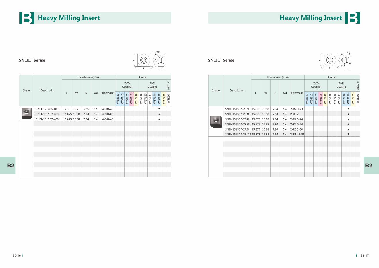
B2 Heavy Milling Insert
B-03 — 04
B1-01 — 02
B1-03
B1-04
B1-05 — 19
Overview
B1-20 — 25
B2-02 — 03
B2-04
B2-05 — 22
B2-23
The Explanation Of Grade
The Explanation Of Specification
Series
Feature
Application Case
Overview
The Explanation Of Specification
Series
Application Case
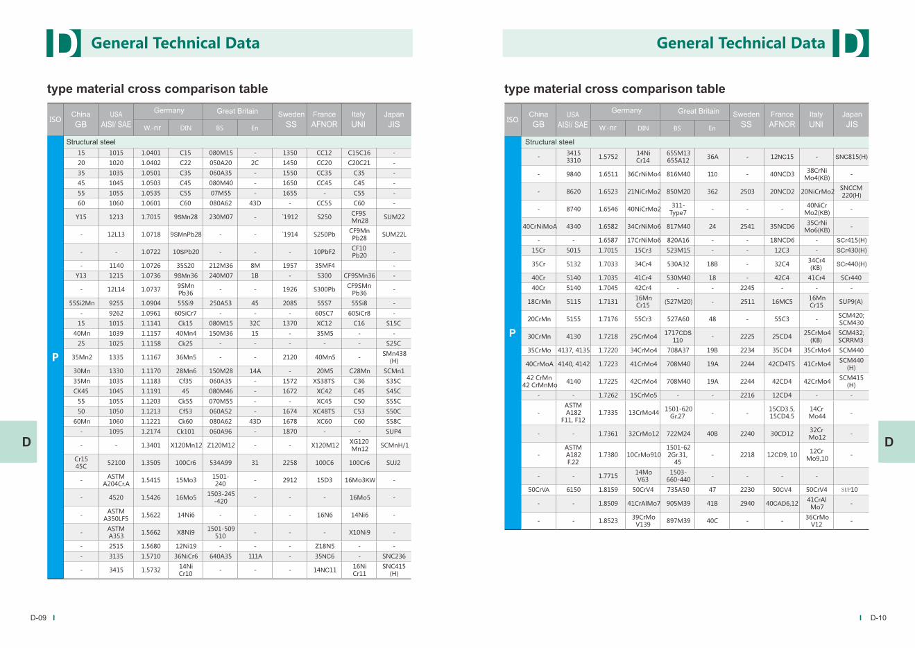
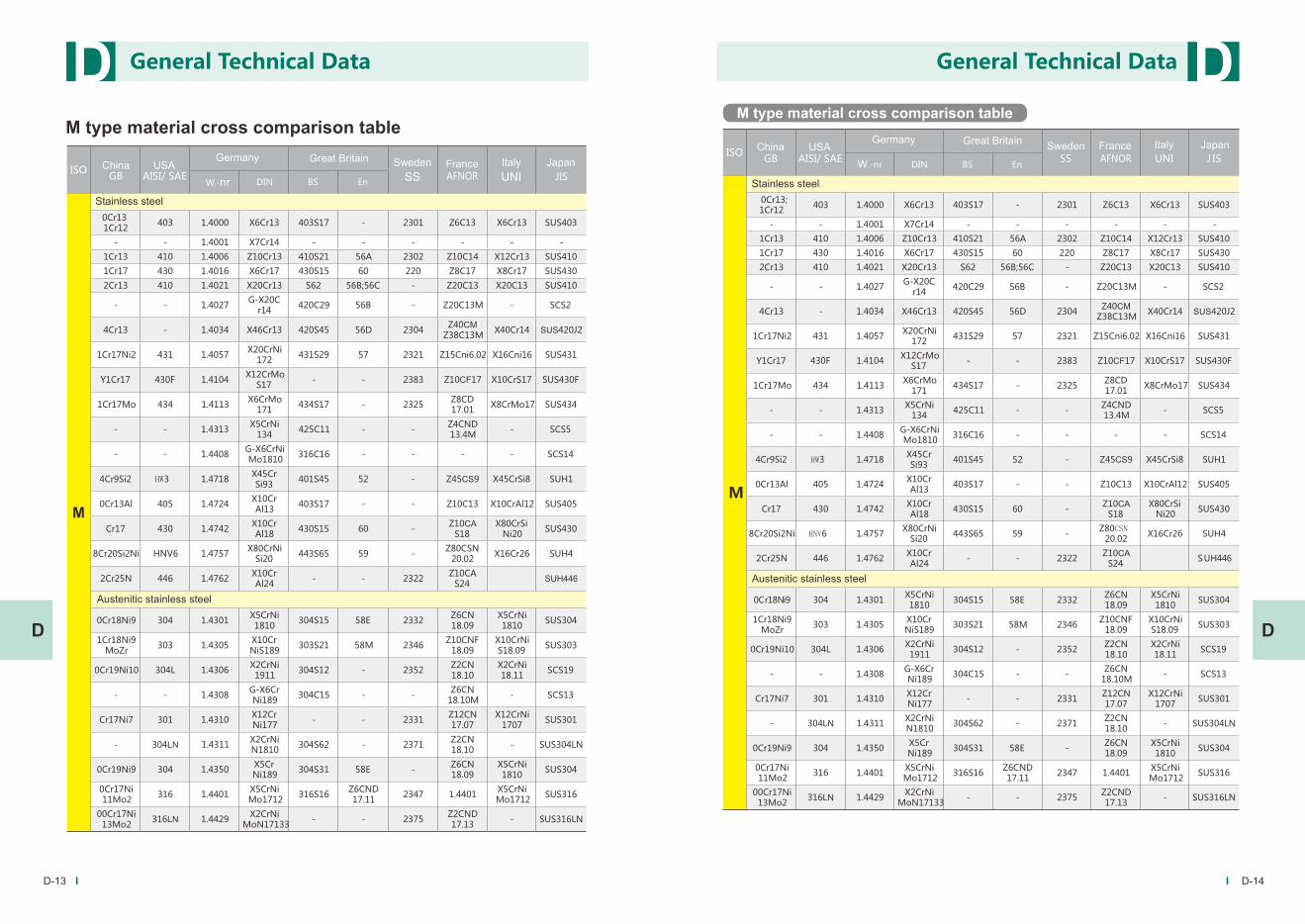
Relevsnt Information Of Cemented Carbide
Relevant Information Of Workpiece
Other Technical Information
D-02 — 08
D-09 — 16
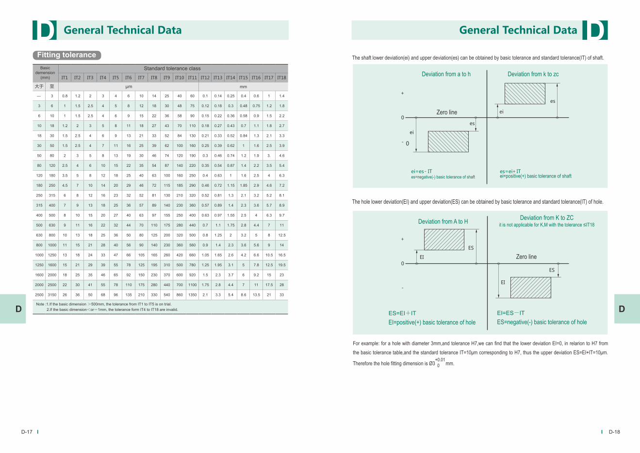
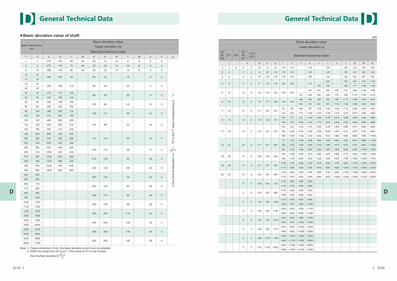
D-17 — 22
Series
Feature
Application Case
C-02
C-03 — 04
C-05 — 06
Page 4
A-02 A-03
● Negative Inserts
AKAluminium machining G
ap: 0.10~ 8.00fn: 0.10~ 0.50
● Positive Inserts With Hole
The Explanation Of Chip-breaker
Chip-breaker Shape and features Using for Precision Recommended Parameters
BF
Map: 0.15~2.00fn: 0.08~0.18
BM
Map: 0.50~8.50fn: 0.10~0.55
BR
Map: 1.50~11.00fn: 0.15~1.00
MT
M
MP
Double-sided chipbreaker,it is suitable for steel machining
and has wide application. Steel
machiningM
M
ap: 1.00~ 5.00 fn: 0.20~ 0.5
ap: 1.00~ 4.00 fn: 0.20~ 0.5
ap: 0.10~ 3.6
fn: 0.03~ 0.4 M
Non
Map: 0.20~12.00fn: 0.10~1.20
Universal Recommended chipbreaker type for general machining it is suitable for K-type material.
Cast ironmachining
Map: 0.20~8.00fn: 0.15~0.60
Turning InsertA A
A A
GT
GF
M
M
ap: 0.15~2.00fn: 0.08~0.18
ap:1.00~5.0fn:0.20~0.50
Turning Insert
It is suitable for steel machining and has wide application.
It is suitable for Steel finish machining.
It is universal chipbreaker,used for semi-finishing and
roughing,the nose and cutting edge sharp and strong.
For finishing of M-type materialdouble-sided chipbreaker,
it has sharp edges, which can effectively cut off stainless
steel and solve the problem of surface hardening, etc
For semi-finishing of M-type material,double-sided chipbreaker,
it is suitable for stainless steel machining and has wide application. "
For rough finishing of M-type material
double-sided chipbreaker, the chipbreaker has been optimized, it has wide
application for light load rough machining of stainless steel.
Steel
machining
Steel
machining
Steel
machining
Stainless steel
machining
Stainless steel
machining
Stainless steel
machining
Chip-breaker Shape and features Using for Precision Recommended Parameters
For cast iron machining the cutting edge is very strong ,it is
the first choice for cast iron machining
Chip-breaker Shape and features Using for Precision Recommended Parameters
For stainless steel
The hole processing has better comprehensive performance
and strong versatility.
Recommended chipbreaker for machining of Al alloy large rake angle and sharping cutting edge, it can achieve easy and fast cutting. Due to surface polishing treatment, It has goodresistance to adhesive performance. "
Cast ironmachining
Stainless steel
machining
Page 5
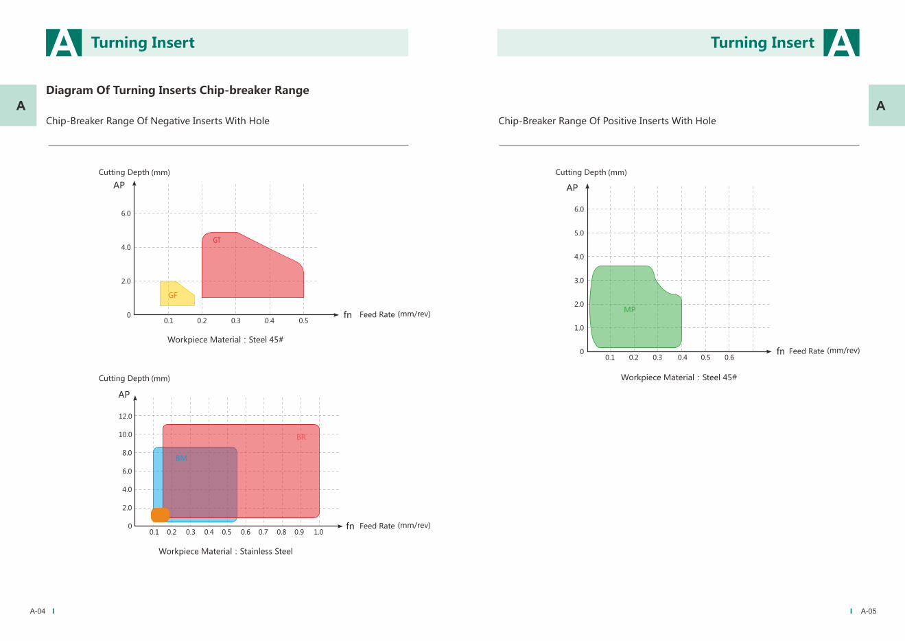
Chip-Breaker Range Of Negative Inserts With Hole
6.0
5.0
4.0
3.0
2.0
1.0
00.1 0.2 0.3 0.4 0.5 0.6
fn
AP
MP
Diagram Of Turning Inserts Chip-breaker Range
A-04 A-05
12.0
10.0
8.0
6.0
4.0
2.0
0 0.1 0.2 0.3 0.4 0.5 0.6 0.7 0.8 0.9
AP
fn
BM
BF
Turning InsertA Turning Insert A
A A
BR
1.0
6.0
4.0
2.0
00.1 0.2 0.3 0.4 0.5
Feed Rate (mm/rev)fn
Cutting Depth (mm)
AP
GF
GT
Workpiece Material:Steel 45#
Cutting Depth (mm)
Feed Rate (mm/rev)
Workpiece Material:Stainless Steel
Chip-Breaker Range Of Positive Inserts With Hole
Cutting Depth (mm)
Feed Rate (mm/rev)
Workpiece Material:Steel 45#
Page 6
The Instruction Of Grade
45403530252015100501
P10~P20
P15~P30
P15~P30
K05~K10
K10~K20
ISO
It is suitable for the stable turning environment and the pursuit of high wear resistance; processing general steel, when the cooling is better, the Vc can reach more than 350m/min.
It is firstly grade for general steel turning, from finishing to rough machining, it has strong comprehensive performance from low speed to high speed, and also can be competent for general interrupted turning.
It is suitable for the high speed of parting and groving turning.
It is the most abrasion resistant material grades for turning of Gray iron and Cast iron ; it also can be used for high hardness and high wear resistant steel pieces of dry cutting.
It is the firstly grade for turning of Gray iron and Cast iron, good comprehensive performance, it is also suitable for general intermittent processing. it can be used for lower speed roughing of quenched steel and high strength steel.
It is special grade for threading turning which used for steel, stainless steel, cast iron and other materials.
TiN+MT-TiCN+Al2O3
+TiN
TiN+MT-TiCN+Al2O3
AlTiN
AlTiN
Thick
TiN+MT-TiCN+Al2O3
+TiN
TiN+MT-TiCN+Al2O3
+TiN
TiN+MT-TiCN+Al2O3
WS8115
WS8125
WS8123
WS6105
WS6115
WS5125
WS7125
WSK10
CVDDouble Color black-yellow
gold-yellow
Black
PVD Grey Black
Un-Coated Silver gray
PVD
Grade
Coating Strucuture
CoatingWay
Coating Color Pictures Component
Application
Wear Resistanoe Toughness
P10~P25
M10~M25
K10~K25
P15~P30
M15~M30
K15~K30
K05~K10
A-06 A-07
CVD
CVD
CVD
CVD
Thin
Range
A A
A A
Turning Insert Turning Insert
Double Color black-yellow
Black
Grey Black
Thick
Thick
Thick-
Thick+
Thin
It is the firstly grade of stainless steel parting and grooving inserts,It meets the middle and low speed cutting and cutting requirements of steel and cast iron.
It is suitable for the vehicle and milling of nonferrous metal materials, graphite and cast iron , aluminum, copper and other materials. It can also be used for low speed turning of titanium alloy and high temperature alloy.
Page 7
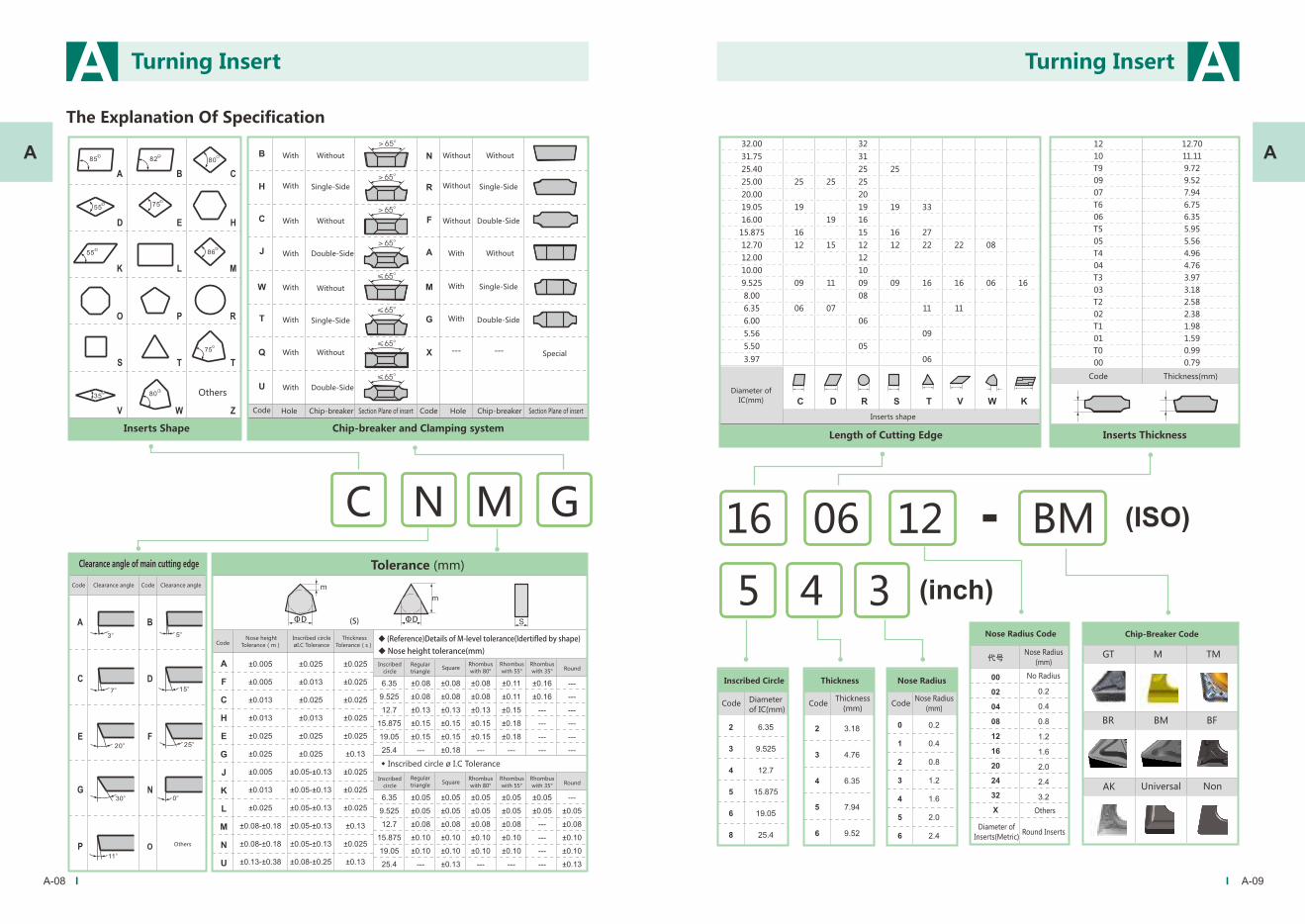
The Explanation Of Specification
(S)
◆�(Reference)Details�of�M-level�tolerance(Idertifled�by�shape)
◆�Nose�height�tolerance(mm)
ΦD ΦD
Tolerance (mm)
◆ Inscribed circle ø I.C Tolerance
C GN M
32.00 32
31.75 31
25.40 25 25
25.00 25 25 25
20.00 20
19.05 19 19 19 33
16.00 19 16
15.875 16 15 16 27
12.70 12 15 12 22 22 08
12.00 12
10.00 10
9.525 09 11 09 09 16 16 06 16
8.00 08
6.35 06 07 11 11
6.00 06
5.56 09
5.50 05
3.97 06
12 12.70
10 11.11
T9 9.72
09 9.52
07 7.94
T6 6.75
06 6.35
T5 5.95
05 5.56
T4 4.96
04 4.76
T3 3.97
03 3.18
T2 2.58
02 2.38
T1 1.98
01 1.59
T0 0.99
00 0.79
5 4 3
16 06 12 BM
GT M TM
BR BM BF
AK
A-08 A-09
A A
A A
Universal Non
Turning Insert Turning Insert
With
With
With
With
With
With
With
With
Without
Single-Side
Without
Double-Side
Single-Side
Without
Without
Double-Side
Without
Without
Without
With
With
With
Without
Single-Side
Double-Side
Without
Single-Side
Double-Side
Special
Code Hole Chip-breaker Section Plane of insert Code Hole Chip-breaker Section Plane of insert
Inserts Shape Chip-breaker and Clamping system
Clearance angle of main cutting edge
Code CodeClearance angle Clearance angle
CodeNose height
Tolerance(m)
Inscribed circle
øI.C Tolerance
Thickness
Tolerance(s)
Inscribed
circle
Regular
triangleSquare
Rhombus
with 80°
Rhombus
with 55°
Rhombus
with 35°Round
Inscribed
circleSquare
Rhombus
with 80°
Rhombus
with 55°
Rhombus
with 35°Round
Regular
triangle
Others
Diameter of
IC(mm)
Inserts shape
Length of Cutting Edge Inserts Thickness
Code Thickness(mm)
Inscribed Circle Thickness Nose Radius
CodeDiameter
of IC(mm)Code
Thickness
(mm)Code
Nose Radius
(mm)
Nose Radius Code Chip-Breaker Code
Nose Radius
(mm)
No Radius
Others
Diameter of
Inserts(Metric)Round Inserts
Others
12
Page 8
Overview
CNMG*-MT
● Negative inserts
A-10 A-11
CNMG *-BF CNMG *-BM CNMG*-BR CNMG* CNMA *
DNMG*-MT DNMG*-BF DNMG*-BM DNMG* DNMA*
SNMG*-M SNMG*-BF SNMG*-BM SNMG *SNMG*-BR SNMA*
TNMG*-MT TNMG*-BF TNMG*-BM TNMG *TNMG*-BR TNMA*TNMG*-M
VNMG *-MT VNMG*-BF VNMG* VNMA *
WNMG*-MT WNMG*-BF WNMG*-BM WNMG*WNMG*-BR WNMA*WNMG*-M
CCMT *-MP
● Positive Inserts
DCMT *-MP SCMT *-MP TCMT *-MP TCMT * RCMX*
DCGT*
● Aluminium Inserts
DCGT* TCGT * VCGT *
A A
A A
VNMG-BM
CNMG *-GF CNMG *-GT
DNMG*-GF DNMG*-GT
SNMG*-GF SNMG*-GT
TNMG*-GF TNMG*-GT
VNMG *-GF VNMG *-GT
WNMG*-GF WNMG*-GT
Turning Insert Turning Insert
Page 9
A1-02
A
A1
Features of turning inserts machining steel
◆Specific groove design can effectively control chip flow direction, which makes the cutting process brisk
and improve the inserts’ service life.
◆Small cutting force efficiently reducing the cutting vibration, obtain high quality finished surface.
◆Optimize the combination of substrate and coating, contribute to more stable and reducing the accidental
failure of the inserts caused by the peeling of the coating in the machining process.
◆Optimized design of the roughing cutting edge to balance the safety and sharpness, improve the tool
performance.
Features of chip-breaker
◆ +6° front angle with the rake face, form a large arc
smooth transition design, smooth cutting and
versatility.
MT
M
◆ Light cutting semi-finishing for light cutting with stable
processing for medium and low speed applications with
poor rigidity.
◆ Improved cutting edge safety and reliability in
intermittent and rough machining.
◆ Good chip evacuation performance and versatility.
Negative Inserts
GF
GT
◆ Used for finishing and semi-finishing;
◆ Large positive rake angle for smaller cutting resistance;
◆ Positive cutting edge inclination design effectively
controls the flow of chips, good chip evacuation achieved;
◆ Coating post-treatment technology improves the wear
resistance and makes the surface more gloss.
◆ Used for semi-finishing and roughing;
◆ The nose and cutting edge sharp and strong;
◆ Variable rake angle design combined with spherical
chipbreaker, suitable for a wider processing range;
◆ Good chip evacuation performance and versatility.
Page 10
A1-03 A1-04
A A
L S Φd IC Re
55° DN□□With Hole
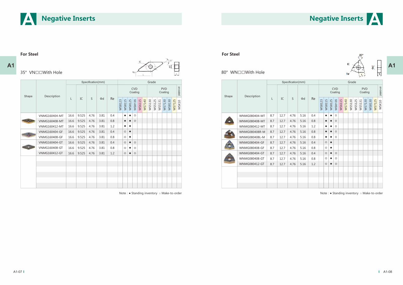
For Steel
A1 A1
Series
For Steel
DescriptionShapeL S Φd
CVDCoating
Specification(mm) Grade
PVDCoating
un-coated
IC
12.9
12.9
12.9
12.7
12.7
12.7
4.76
4.76
4.76
5.16
5.16
5.16
CNMG120404-MT
CNMG120408-MT
CNMG120412-MT
Re
0.4
0.8
1.2
80° CN□□With Hole
WS
8135
WS
81
35
Note:● Standing inventory ○ Make-to-order
CNMG120404-GF
CNMG120408-GF
CNMG120404-GT
CNMG120408-GT
CNMG120412-GT
12.9
12.9
12.9
12.9
12.9
12.7
12.7
12.7
12.7
12.7
4.76
4.76
4.76
4.76
4.76
5.16
5.16
5.16
5.16
5.16
0.4
0.8
0.4
0.8
1.2
DNMG150404-MT
DNMG150408-MT
DNMG150404-GF
DNMG150604-GF
DNMG150408-GF
DNMG150608-GF
DNMG150404-GT
DNMG150604-GT
DNMG150408-GT
DNMG150608-GT
DNMG150412-GT
DNMG150612-GT
15.5
15.5
15.5
15.5
15.5
15.5
15.5
15.5
15.5
15.5
15.5
15.5
12.7
12.7
12.7
12.7
12.7
12.7
12.7
12.7
12.7
12.7
12.7
12.7
4.76
4.76
4.76
6.35
4.76
6.35
4.76
6.35
4.76
6.35
4.76
6.35
5.16
5.16
5.16
5.16
5.16
5.16
5.16
5.16
5.16
5.16
5.16
5.16
0.4
0.8
0.4
0.4
0.8
0.8
0.4
0.4
0.8
0.8
1.2
1.2
Negative InsertsNegative Inserts
Specification(mm)
DescriptionShape
CVDCoating
PVDCoating
un-coated
Note:● Standing inventory ○ Make-to-order
Grade
Page 11
A1-05 A1-06
A A
L S Φd IC Re
0.4
0.8
1.2
0.4
0.4
0.8
0.8
0.4
0.8
0.4
0.8
1.2
60° TN□□With Hole
TNMG160404-MT
TNMG160408-MT
TNMG160412-MT
TNMG160404R-M
TNMG160404L-M
TNMG160408R-M
TNMG160408L-M
TNMG160404-GF
TNMG160408-GF
TNMG160404-GT
TNMG160408-GT
TNMG160412-GT
16.5
16.5
16.5
16.5
16.5
16.5
16.5
16.5
16.5
16.5
16.5
16.5
9.525
9.525
9.525
9.525
9.525
9.525
9.525
9.525
9.525
9.525
9.525
9.525
4.76
4.76
4.76
4.76
4.76
4.76
4.76
4.76
4.76
4.76
4.76
4.76
3.81
3.81
3.81
3.81
3.81
3.81
3.81
3.81
3.81
3.81
3.81
3.81
A1 A1
L S Φd IC Re
90° SN□□With Hole
WS
8135
WS
81
35
SNMG120408R-M
SNMG120408L-M
SNMG120404-GF
SNMG120408-GF
SNMG120404-GT
SNMG120408-GT
SNMG120412-GT
12.7
12.7
12.7
12.7
12.7
12.7
12.7
12.7
12.7
12.7
12.7
12.7
12.7
12.7
4.76
4.76
4.76
4.76
4.76
4.76
4.76
5.16
5.16
5.16
5.16
5.16
5.16
5.16
0.8
0.8
0.4
0.8
0.4
0.8
1.2
Negative InsertsNegative Inserts
For SteelFor Steel
DescriptionShape
CVDCoating
Specification(mm) Grade
PVDCoating
un-coated
Note:● Standing inventory ○ Make-to-order
Specification(mm)
DescriptionShape
CVDCoating
PVDCoating
un-coated
Note:● Standing inventory ○ Make-to-order
Grade
Page 12
A1-07 A1-08
A A
A1 A1
L S Φd IC Re
80° WN□□With Hole
L S Φd IC Re
35° VN□□With HoleL
35°
S
ød
IC
Re
WS
8135
WS
81
35
VNMG160404-MT
VNMG160408-MT
VNMG160412-MT
VNMG160404-GF
VNMG160408-GF
VNMG160404-GT
VNMG160408-GT
VNMG160412-GT
16.6
16.6
16.6
16.6
16.6
16.6
16.6
16.6
9.525
9.525
9.525
9.525
9.525
9.525
9.525
9.525
4.76
4.76
4.76
4.76
4.76
4.76
4.76
4.76
3.81
3.81
3.81
3.81
3.81
3.81
3.81
3.81
0.4
0.8
1.2
0.4
0.8
0.4
0.8
1.2
WNMG080404-MT
WNMG080408-MT
WNMG080412-MT
WNMG080408R-M
WNMG080408L-M
WNMG080404-GF
WNMG080408-GF
WNMG080404-GT
WNMG080408-GT
WNMG080412-GT
8.7
8.7
8.7
8.7
8.7
8.7
8.7
8.7
8.7
8.7
12.7
12.7
12.7
12.7
12.7
12.7
12.7
12.7
12.7
12.7
4.76
4.76
4.76
4.76
4.76
4.76
4.76
4.76
4.76
4.76
5.16
5.16
5.16
5.16
5.16
5.16
5.16
5.16
5.16
5.16
0.4
0.8
1.2
0.8
0.8
0.4
0.8
0.4
0.8
1.2
Negative InsertsNegative Inserts
For SteelFor Steel
DescriptionShape
CVDCoating
Specification(mm) Grade
PVDCoating
un-coated
Note:● Standing inventory ○ Make-to-order
Specification(mm)
DescriptionShape
CVDCoating
PVDCoating
un-coated
Note:● Standing inventory ○ Make-to-order
Grade
Page 13
A1-09 A1-10
A A
A1 A1
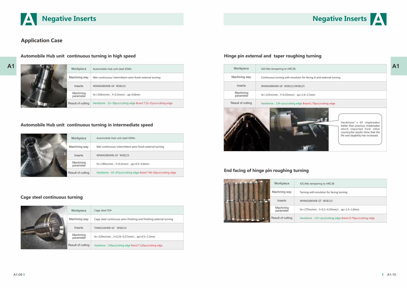
Cage steel continuous turning
Cage steel 55#
Cage steel continuous semi-finishing and finishing external turning
TNMG160408-GF WS8115
Vc=320m/min,f=0.24~0.27mm/r,ap=0.5~1.5mm
Hardstone:130pcs/cutting edge Brand T:120pcs/cutting edge
Hinge pin external and taper roughing turning
42CrMo tempering to HRC38
Continuous turning with emulsion for facing A and external turning
WNMG080408-GF WS8115/WS8125
Vc=125m/min,f=0.25mm/r,ap=1.0~2.5mm
Hardstone:134+pcs/cutting edge Brand L:76pcs/cutting edge
End facing of hinge pin roughing turning
42CrMo tempering to HRC38
Turning with emulsion for facing turning
WNMG080408-GT WS8115
Vc=175m/min,f=0.2~0.25mm/r,ap=1.5~1.8mm
Hardstone:152+pcs/cutting edge Brand O:70pcs/cutting edge
Automobile Hub unit continuous turning in high speed
Automobile Hub unit steel 65Mn
Wet continuous/ intermittent semi-finish external turning
WNMG080408-GF WS8115
Vc=330m/min,f=0.3mm/r,ap=0.8mm
Hardstone:23~30pcs/cutting edge Brand T:13-21pcs/cutting edge
Workpiece
Machining way
Inserts
Machining parameter
Result of cutting
Automobile Hub unit continuous turning in intermediate speed
Automobile Hub unit steel 65Mn
Wet continuous/ intermittent semi-finish external turning
WNMG080408-GF WS8125
Vc=190m/min,f=0.2mm/r,ap=0.5~0.6mm
Hardstone:63~87pcs/cutting edge Brand T:40-65pcs/cutting edge
Hardstone’s GF chipbreaker
better than previous chipbreaker
which imported from other
country,the results show that the
life and stqability has increased.
Negative InsertsNegative Inserts
Workpiece
Machining way
Inserts
Machining parameter
Result of cutting
Workpiece
Machining way
Inserts
Machining parameter
Result of cutting
Workpiece
Machining way
Inserts
Machining parameter
Result of cutting
Workpiece
Machining way
Inserts
Machining parameter
Result of cutting
Application Case
Page 14
A1-11 A1-12
A A
A1 A1Automobile Hub unit steel 55#
Wet continuous/ intermittent semi-finish external turning
WNMG080408-MT WS8125
Vc=220~300m/min,f=0.15~0.28mm/r,ap=0.8mm
Hardstone:80~100pcs/cutting edge Brand T:70-90pcs/cutting edge
Automobile Hub unit intermittent / continuous turning
Bearing pedestal intermittent turning
Automobile Hub bearing pedestal steel 55#
Wet continuous/ intermittent semi-finishding and finishing external turning
WNMG080408-GT WS8125
Vc=259m/min,f=0.18~0.275mm/r,ap=0.5~1mm
Hardstone:78pcs/cutting edge Brand D:40-50pcs/cutting edge
End facing of housing continuous roughing turning
steel 55#
Wet intermittent turning
WNMG080408-GT WS8125
Vc=209m/min,f=0.25mm/r,ap=1.8mm
Hardstone:100~130pcs/cutting edge Brand T:110~140pcs/cutting edge
Automobile Hub unit hole intermittent / continuous turning
Automobile Hub unit steel 65Mn
Wet intermittent semi-finishing turning
VNMG160408-MT WS8115
Vc=300m/min,f=0.24mm/r,ap=0.5mm
Hardstone:160~180pcs/cutting edge Brand T:160~180pcs/cutting edge
Flange intermittent / continuous turning in high speed
Flange steel 55#
Wet journal shaft continuous/ intermittent finishing turning
VNMG160408-MT WS8115
Vc=230~510m/min,f=0.167mm/r,ap=0.45mm
Hardstone:20~21pcs/cutting edge Brand T:15-16pcs/cutting edge
Automobile Hub bearing pedestal steel 65Mn
Wet continuous/ intermittent semi-finishing external turning
WNMG080408-GT WS8125
Vc=230m/min,f=0.22mm/r,ap=0.8mm
Hardstone:55~65pcs/cutting edge Brand T:50~60pcs/cutting edge
Bearing pedestal intermittent turning
Negative InsertsNegative Inserts
Workpiece
Machining way
Inserts
Machining parameter
Result of cutting
Workpiece
Machining way
Inserts
Machining parameter
Result of cutting
Workpiece
Machining way
Inserts
Machining parameter
Result of cutting
Workpiece
Machining way
Inserts
Machining parameter
Result of cutting
Workpiece
Machining way
Inserts
Machining parameter
Result of cutting
Workpiece
Machining way
Inserts
Machining parameter
Result of cutting
Page 15
A1-13 A1-14
A A
A1 A1
Piston rod roughing turning
27SiMn
Dry roughing turning
TNMG160408R-M WS8125
Vc=100m/min,f=0.4mm/r,ap=2.5mm
Hardstone:50~60pcs/cutting edge
Brand Z:its fail when machining cause vibration is too large.
Bearing turning
Bearing Gcr15
Wet rough turning with facing B and external turning
WNMG080408-MT WS8125
Vc=260m/min,f=0.32mm/r,ap=2mm
Hardstone:130~150pcs/cutting edge Brand T:130~150pcs/cutting edge
Bearing turning
Bearing Gcr15
Wet rough turning with facing A and chamfer turning
WNMG080408-MT WS8125
Vc=369m/min,f=0.31mm/r,ap=1mm
Hardstone:65~72pcs/cutting edge Brand T:60~70pcs/cutting edge
Steel 45#
Wet continuous semi-finishing turning
CCMT09T308-TM WS8115
Vc=238m/min,f=0.14~0.26mm/r,ap=1mm
Hardstone:882~908pcs/cutting edge Brand T:600~850pcs/cutting edge
Spherical shells hole turning
Housing intermittent / continuous roughing turning
Cf53
Wet continuous/ intermittent semi-finish external turning
DNMG150408-MT WS8125
Vc=286m/min,f=0.33mm/r,ap=0.2mm
Hardstone:46~63pcs/cutting edge Brand T:40~50pcs/cutting edge
Housing intermittent roughing turning
Steel Cf53
Wet journal shaft intermittent finishing turning
CNMG120408-MT WS8125
Vc=220m/min,f=0.2mm/r,ap=1.5mm
Hardstone:40~50pcs/cutting edge Brand T:30~40pcs/cutting edge
Negative InsertsNegative Inserts
Workpiece
Machining way
Inserts
Machining parameter
Result of cutting
Workpiece
Machining way
Inserts
Machining parameter
Result of cutting
Workpiece
Machining way
Inserts
Machining parameter
Result of cutting
Workpiece
Machining way
Inserts
Machining parameter
Result of cutting
Workpiece
Machining way
Inserts
Machining parameter
Result of cutting
Workpiece
Machining way
Inserts
Machining parameter
Result of cutting
Page 16
A1-16
A
A1
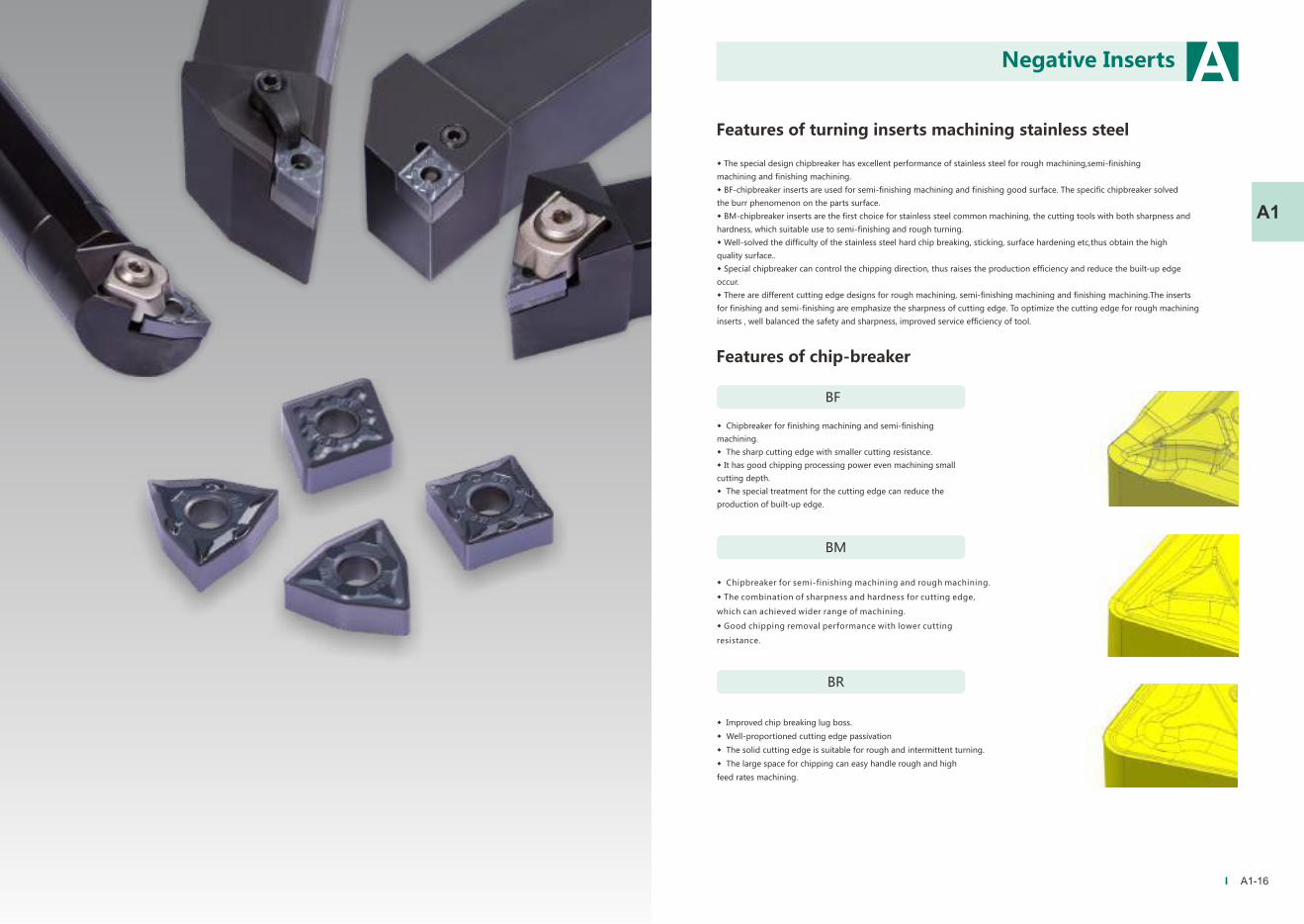
Features of turning inserts machining stainless steel
◆ The special design chipbreaker has excellent performance of stainless steel for rough machining,semi-finishing
machining and finishing machining.
◆ BF-chipbreaker inserts are used for semi-finishing machining and finishing good surface. The specific chipbreaker solved
the burr phenomenon on the parts surface.
◆ BM-chipbreaker inserts are the first choice for stainless steel common machining, the cutting tools with both sharpness and
hardness, which suitable use to semi-finishing and rough turning.
◆ Well-solved the difficulty of the stainless steel hard chip breaking, sticking, surface hardening etc,thus obtain the high
quality surface..
◆ Special chipbreaker can control the chipping direction, thus raises the production efficiency and reduce the built-up edge
occur.
◆ There are different cutting edge designs for rough machining, semi-finishing machining and finishing machining.The inserts
for finishing and semi-finishing are emphasize the sharpness of cutting edge. To optimize the cutting edge for rough machining
inserts , well balanced the safety and sharpness, improved service efficiency of tool.
Features of chip-breaker
BM
BR
◆ Chipbreaker for finishing machining and semi-finishing
machining.
◆ The sharp cutting edge with smaller cutting resistance.
◆ It has good chipping processing power even machining small
cutting depth.
◆ The special treatment for the cutting edge can reduce the
production of built-up edge.
◆ Chipbreaker for semi-finishing machining and rough machining.
◆ The combination of sharpness and hardness for cutting edge,
which can achieved wider range of machining.
◆ Good chipping removal performance with lower cutting
resistance.
◆ Improved chip breaking lug boss.
◆ Well-proportioned cutting edge passivation
◆ The solid cutting edge is suitable for rough and intermittent turning.
◆ The large space for chipping can easy handle rough and high
feed rates machining.
BF
Negative Inserts
Page 17
A1-17 A1-18
A A
A1 A1
L S Φd IC Re
DNMG150404-BF
DNMG150408-BF
DNMG150404-BM
DNMG150408-BM
DNMG150412-BM
DNMG150604-BM
DNMG150608-BM
DNMG150612-BM
15.5
15.5
15.5
15.5
15.5
15.5
15.5
15.5
4.76
4.76
4.76
4.76
4.76
6.35
6.35
6.35
5.16
5.16
5.16
5.16
5.16
5.16
5.16
5.16
0.4
0.8
0.4
0.8
1.2
0.4
0.8
1.2
12.7
12.7
12.7
12.7
12.7
12.7
12.7
12.7
55° DN□□With Hole
WS5130
WS5125
WS5131
WS7130
WS8130
WS7125
WSK
10
WS8123
WS8115
WS8125
WS6115
WS7140
Series
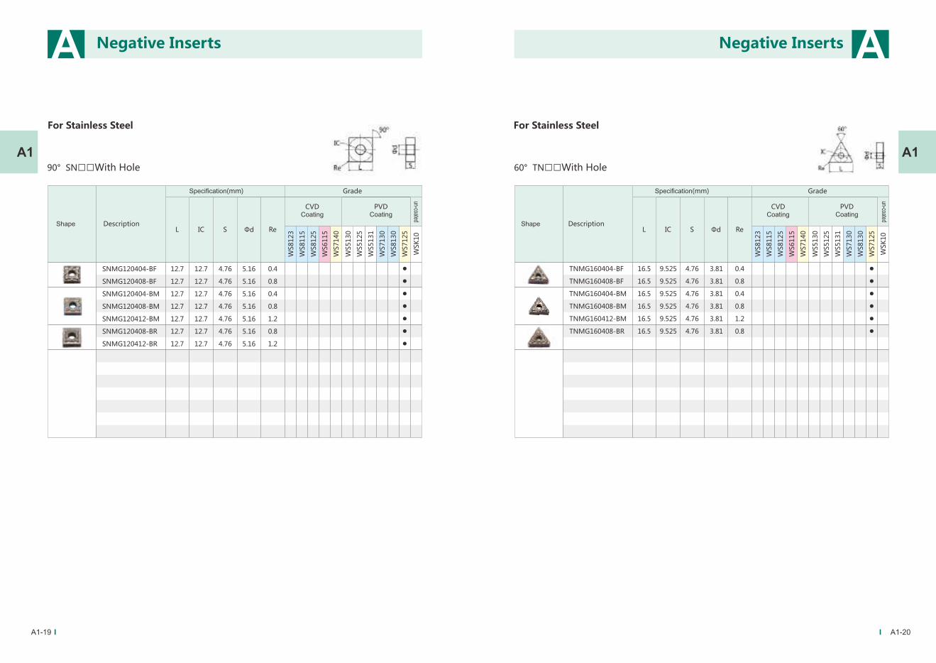
For Stainless Steel
L S Φd IC Re
80° CN□□With Hole
CNMG120404-BF
CNMG120408-BF
CNMG120404-BM
CNMG120408-BM
CNMG120412-BM
CNMG120408-BR
CNMG120412-BR
CNMG190616-BR
12.9
12.9
12.9
12.9
12.9
12.9
12.9
19.3
4.76
4.76
4.76
4.76
4.76
4.76
4.76
6.35
5.16
5.16
5.16
5.16
5.16
5.16
5.16
7.94
0.4
0.8
0.4
0.8
1.2
0.8
1.2
1.6
12.7
12.7
12.7
12.7
12.7
12.7
12.7
19.05
WS5130
WS5125
WS5131
WS7130
WS8130
WS7125
WSK
10
WS8123
WS8115
WS8125
WS6115
WS7140
Negative InsertsNegative Inserts
For Stainless Steel
DescriptionShape
CVDCoating
Specification(mm) Grade
PVDCoating
un-coated
Specification(mm)
DescriptionShape
CVDCoating
PVDCoating
un-coated
Grade
Page 18
A1-19 A1-20
A A
A1 A1
L S Φd IC Re
60° TN□□With Hole
TNMG160404-BF
TNMG160408-BF
TNMG160404-BM
TNMG160408-BM
TNMG160412-BM
TNMG160408-BR
16.5
16.5
16.5
16.5
16.5
16.5
4.76
4.76
4.76
4.76
4.76
4.76
3.81
3.81
3.81
3.81
3.81
3.81
0.4
0.8
0.4
0.8
1.2
0.8
9.525
9.525
9.525
9.525
9.525
9.525
WS5130
WS5125
WS5131
WS7130
WS8130
WS7125
WSK
10
WS8123
WS8115
WS8125
WS6115
WS7140L S Φd IC Re
90° SN□□With Hole
SNMG120404-BF
SNMG120408-BF
SNMG120404-BM
SNMG120408-BM
SNMG120412-BM
SNMG120408-BR
SNMG120412-BR
12.7
12.7
12.7
12.7
12.7
12.7
12.7
4.76
4.76
4.76
4.76
4.76
4.76
4.76
5.16
5.16
5.16
5.16
5.16
5.16
5.16
0.4
0.8
0.4
0.8
1.2
0.8
1.2
12.7
12.7
12.7
12.7
12.7
12.7
12.7W
S5130
WS5125
WS5131
WS7130
WS8130
WS7125
WSK
10
WS8123
WS8115
WS8125
WS6115
WS7140
Negative InsertsNegative Inserts
For Stainless Steel For Stainless Steel
DescriptionShape
CVDCoating
Specification(mm) Grade
PVDCoating
un-coated
Specification(mm)
DescriptionShape
CVDCoating
PVDCoating
un-coated
Grade
Page 19
A
A1
L S Φd IC Re
35° VN□□With Hole
VNMG160404-BF
VNMG160408-BF
16.6
16.6
16.6
16.6
16.6
4.76
4.76
4.76
4.76
4.76
3.81
3.81
3.81
3.81
3.81
0.4
0.8
0.4
0.8
1.2
9.525
9.525
9.525
9.525
9.525
WS5130
WS5125
WS5131
WS7130
WS8130
WS7125
WSK
10
WS8123
WS8115
WS8125
WS6115
WS7140
L
35°
S
IC
ød
Re
VNMG160404-BM
VNMG160408-BM
VNMG160412-BM
L S Φd IC Re
80° WN□□With Hole
WNMG080404-BF
WNMG080408-BF
WNMG06T312-BM
WNMG060412-BM
WNMG080404-BM
WNMG080408-BM
WNMG080412-BM
WNMG080408-BR
4.76
4.76
3.97
4.76
4.76
4.76
4.76
4.76
5.16
5.16
3.81
3.81
5.16
5.16
5.16
5.16
0.4
0.8
1.2
1.2
0.4
0.8
1.2
0.8
12.7
12.7
9.525
9.525
12.7
12.7
12.7
12.7
8.7
8.7
6.6
6.6
8.7
8.7
8.7
8.7
WS5130
WS5125
WS5131
WS7130
WS8130
WS7125
WSK
10
WS8123
WS8115
WS8125
WS6115
WS7140
A
A1
Flange finishing turning
Flange roughing turning
Flange finishing turning
Stainless steel SUS304
Continuous external finishing turning
WNMG080408-BF WS7125
Vc=220m/min,f=0.14mm/r,ap=0.1mm(Ra≤0.8)
Surface roughness: lower than Ra1.6 Hardstone, 242 pieces / cutting edge
Brand C: 212 pieces /cutting edge
Stainless steel SUS304
Continuous external finishing turning
WNMG080408-BF WS7125
Vc=210m/min,f=0.1mm/r,ap=0.1mm(Ra≤0.8)
Surface roughness: lower than Ra1.6 Hardstone, 740 pieces / cutting edge
Brand Z: 450 pieces /cutting edge
Stainless steel SUS201
The continuous turning for end face and excircle
WNMG080408-BM WS7125
Vc=273m/min,f=0.3mm/r,ap=1.0mm
Hardstone:37~42pcs/cutting edge
Brand M:38~42pcs/cuttting edge
A1-21 A1-22
Negative InsertsNegative Inserts
For Stainless Steel
DescriptionShape
CVDCoating
Specification(mm) Grade
PVDCoating
un-coated
DescriptionShape
CVDCoating
Specification(mm) Grade
PVDCoating
un-coated
Workpiece
Machining way
Inserts
Machining parameter
Result of cutting
Workpiece
Machining way
Inserts
Machining parameter
Result of cutting
Workpiece
Machining way
Inserts
Machining parameter
Result of cutting
Application Case
Page 20
A1-24
A
A1
Series
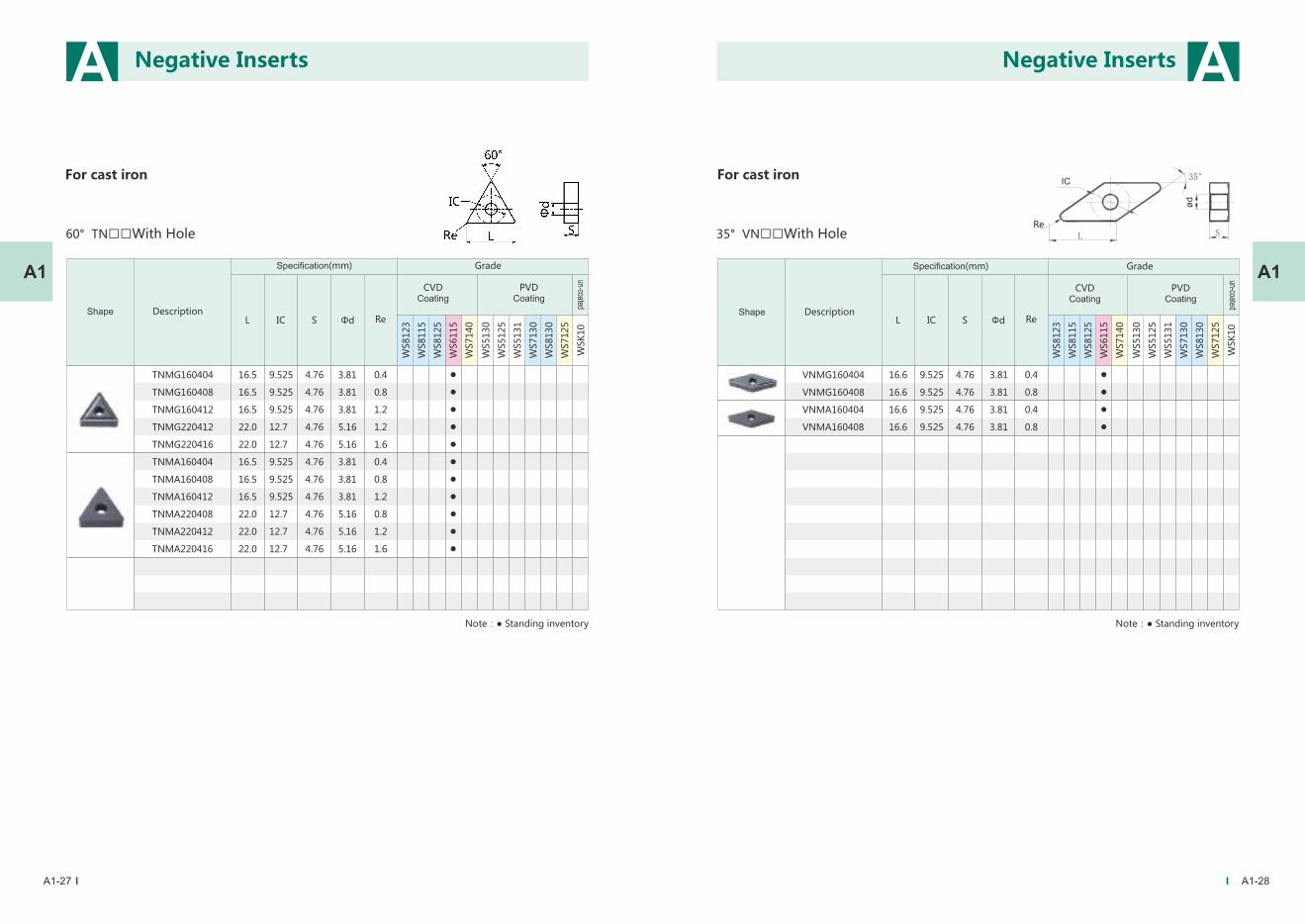
For cast iron
L S Φd IC Re
80° CN□□With Hole
WS5130
WS5125
WS5131
WS7130
WS8130
WS7125
WSK
10
WS8123
WS8115
WS8125
WS6115
WS7140
CNMG120404
CNMG120408
CNMG120412
CNMG120416
CNMG160608
CNMG160612
CNMG160616
CNMG190612
CNMG190616
CNMA120404
CNMA120408
CNMA120412
CNMA160608
CNMA160612
CNMA160616
CNMA190612
CNMA190616
12.9
12.9
12.9
12.9
16.1
16.1
16.1
19.3
19.3
12.9
12.9
12.9
16.1
16.1
16.1
19.3
19.3
4.76
4.76
4.76
4.76
6.35
6.35
6.35
6.35
6.35
4.76
4.76
4.76
6.35
6.35
6.35
6.35
6.35
5.16
5.16
5.16
5.16
6.35
6.35
6.35
7.94
7.94
5.16
5.16
5.16
6.35
6.35
6.35
7.94
7.94
0.4
0.8
1.2
1.6
0.8
1.2
1.6
1.2
1.6
0.4
0.8
1.2
0.8
1.2
1.6
1.2
1.6
12.7
12.7
12.7
12.7
15.875
15.875
15.875
19.05
19.05
12.7
12.7
12.7
15.875
15.875
15.875
19.05
19.05
Negative Inserts
Specification(mm)
DescriptionShape
CVDCoating
PVDCoating
un-coated
Grade
Note:● Standing inventory
Page 21
A1-25 A1-26
A A
A1 A1
L S Φd IC
90° SN□□With Hole
WS5130
WS5125
WS5131
WS7130
WS8130
WS7125
WSK
10
WS8123
WS8115
WS8125
WS6115
WS7140
ReL S Φd IC
55° DN□□With Hole
WS5130
WS5125
WS5131
WS7130
WS8130
WS7125
WSK
10
WS8123
WS8115
WS8125
WS6115
WS7140
DNMG150404
DNMG150408
DNMG150412
DNMG150604
DNMG150608
DNMG150612
DNMA150404
DNMA150408
DNMA150412
DNMA150604
DNMA150608
DNMA150612
15.5
15.5
15.5
15.5
15.5
15.5
15.5
15.5
15.5
15.5
15.5
15.5
4.76
4.76
4.76
6.35
6.35
6.35
4.76
4.76
4.76
6.35
6.35
6.35
5.16
5.16
5.16
5.16
5.16
5.16
5.16
5.16
5.16
5.16
5.16
5.16
0.4
0.8
1.2
0.4
0.8
1.2
0.4
0.8
1.2
0.4
0.8
1.2
12.7
12.7
12.7
12.7
12.7
12.7
12.7
12.7
12.7
12.7
12.7
12.7
Re
SNMG120404
SNMG120408
SNMG120412
SNMG150608
SNMG150612
SNMG150616
SNMG190612
SNMG190616
SNMA120404
SNMA120408
SNMA120412
SNMA150608
SNMA150612
SNMA150616
SNMA190612
SNMA190616
12.7
12.7
12.7
15.875
15.875
15.875
19.05
19.05
12.7
12.7
12.7
15.875
15.875
15.875
19.05
19.05
4.76
4.76
4.76
6.35
6.35
6.35
6.35
6.35
4.76
4.76
4.76
6.35
6.35
6.35
6.35
6.35
5.16
5.16
5.16
6.35
6.35
6.35
7.94
7.94
5.16
5.16
5.16
6.35
6.35
6.35
7.94
7.94
0.4
0.8
1.2
0.8
1.2
1.6
1.2
1.6
0.4
0.8
1.2
0.8
1.2
1.6
1.2
1.6
12.7
12.7
12.7
15.875
15.875
15.875
19.05
19.05
12.7
12.7
12.7
15.875
15.875
15.875
19.05
19.05
Negative InsertsNegative Inserts
For cast ironFor cast iron
Specification(mm)
DescriptionShape
CVDCoating
PVDCoating
un-coated
GradeSpecification(mm)
DescriptionShape
CVDCoating
PVDCoating
un-coated
Grade
Note:● Standing inventory
Note:● Standing inventory
Page 22
A1-27 A1-28
A A
A1 A1
L S Φd IC
WS5130
WS5125
WS5131
WS7130
WS8130
WS7125
WSK
10
WS8123
WS8115
WS8125
WS6115
WS7140
Re
35° VN□□With Hole
VNMG160404
VNMG160408
VNMA160404
VNMA160408
16.6
16.6
16.6
16.6
4.76
4.76
4.76
4.76
3.81
3.81
3.81
3.81
0.4
0.8
0.4
0.8
9.525
9.525
9.525
9.525
LRe
35°
S
IC
ød
L S Φd IC
60° TN□□With Hole
WS5130
WS5125
WS5131
WS7130
WS8130
WS7125
WSK
10
WS8123
WS8115
WS8125
WS6115
WS7140
Re
TNMG160404
TNMG160408
TNMG160412
TNMG220412
TNMG220416
TNMA160404
TNMA160408
TNMA160412
TNMA220408
TNMA220412
TNMA220416
16.5
16.5
16.5
22.0
22.0
16.5
16.5
16.5
22.0
22.0
22.0
4.76
4.76
4.76
4.76
4.76
4.76
4.76
4.76
4.76
4.76
4.76
3.81
3.81
3.81
5.16
5.16
3.81
3.81
3.81
5.16
5.16
5.16
0.4
0.8
1.2
1.2
1.6
0.4
0.8
1.2
0.8
1.2
1.6
9.525
9.525
9.525
12.7
12.7
9.525
9.525
9.525
12.7
12.7
12.7
Negative InsertsNegative Inserts
For cast ironFor cast iron
Specification(mm)
DescriptionShape
CVDCoating
PVDCoating
un-coated
GradeSpecification(mm)
DescriptionShape
CVDCoating
PVDCoating
un-coated
Grade
Note:● Standing inventory Note:● Standing inventory
Page 23
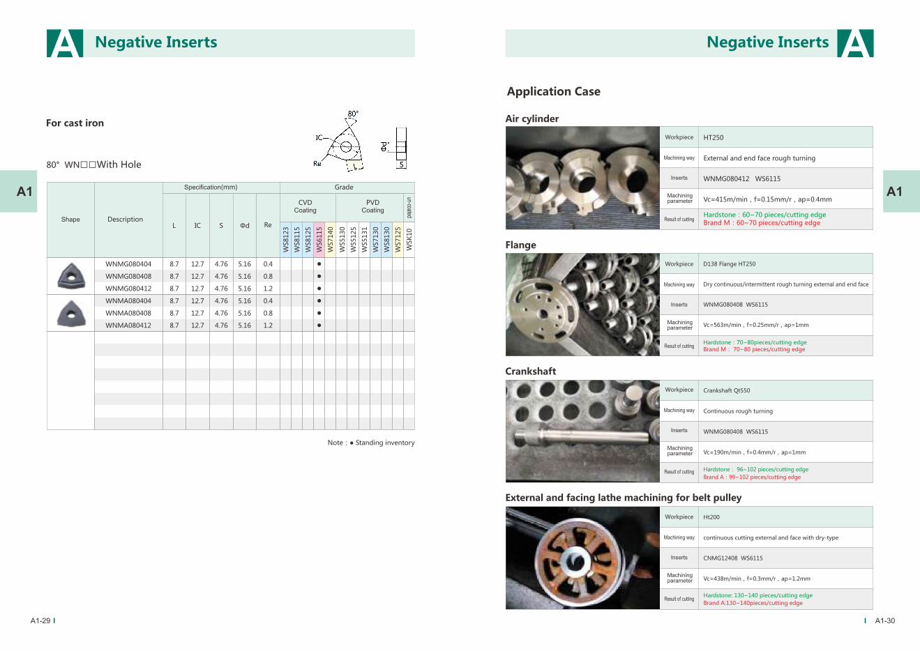
A
Flange
Crankshaft
Air cylinder
D138 Flange HT250
Dry continuous/intermittent rough turning external and end face
WNMG080408 WS6115
Vc=563m/min,f=0.25mm/r,ap=1mm
Hardstone:70~80pieces/cutting edge Brand M: 70~80 pieces/cutting edge
Crankshaft Qt550
Continuous rough turning
WNMG080408 WS6115
Vc=190m/min,f=0.4mm/r,ap=1mm
Hardstone: 96~102 pieces/cutting edge
Brand A:99~102 pieces/cutting edge
HT250
External and end face rough turning
WNMG080412 WS6115
Vc=415m/min,f=0.15mm/r,ap=0.4mm
Hardstone:60~70 pieces/cutting edgeBrand M:60~70 pieces/cutting edge
A1
A
A1
L S Φd IC
80° WN□□With Hole
WS5130
WS5125
WS5131
WS7130
WS8130
WS7125
WSK
10
WS8123
WS8115
WS8125
WS6115
WS7140
Re
WNMG080404
WNMG080408
WNMG080412
WNMA080404
WNMA080408
WNMA080412
8.7
8.7
8.7
8.7
8.7
8.7
4.76
4.76
4.76
4.76
4.76
4.76
5.16
5.16
5.16
5.16
5.16
5.16
0.4
0.8
1.2
0.4
0.8
1.2
12.7
12.7
12.7
12.7
12.7
12.7
A1-29 A1-30
External and facing lathe machining for belt pulley
Ht200
continuous cutting external and face with dry-type
CNMG12408 WS6115
Vc=438m/min,f=0.3mm/r,ap=1.2mm
Hardstone: 130~140 pieces/cutting edge
Brand A:130~140pieces/cutting edge
Negative InsertsNegative Inserts
For cast iron
Specification(mm)
DescriptionShape
CVDCoating
PVDCoating
un-coated
Grade
Note:● Standing inventory
Workpiece
Machining way
Inserts
Machining parameter
Result of cutting
Workpiece
Machining way
Inserts
Machining parameter
Result of cutting
Workpiece
Machining way
Inserts
Machining parameter
Result of cutting
Workpiece
Machining way
Inserts
Machining parameter
Result of cutting
Application Case
Page 24
A2-02
A
L S Φd IC Re
80° CC□□With Hole
CCMT060204-MP
CCMT09T302-MP
CCMT09T304-MP
CCMT09T308-MP
CCMT120404-MP
CCMT120408-MP
CCMT060204-TM
CCMT060208-TM
CCMT09T304-TM
CCMT09T308-TM
CCMT120404-TM
CCMT120408-TM
CCMT120412-TM
6.4
9.7
9.7
9.7
12.9
12.9
6.4
6.4
9.7
9.7
12.9
12.9
12.9
2.38
3.97
3.97
3.97
4.76
4.76
2.38
2.38
3.97
3.97
4.76
4.76
4.76
2.8
4.4
4.4
4.4
5.56
5.56
2.8
2.8
4.4
4.4
5.56
5.56
5.56
0.4
0.2
0.4
0.8
0.4
0.8
0.4
0.8
0.4
0.8
0.4
0.8
1.2
6.35
9.525
9.525
9.525
12.7
12.7
6.35
6.35
9.525
9.525
12.7
12.7
12.7
WS5130
WS5125
WS5131
WS7130
WS8130
WS7125
WSK
10
WS8123
WS8115
WS8125
WS6115
WS7140
A2
Series
Specification(mm)
DescriptionShape
CVDCoating
PVDCoating
un-coated
Grade
Positive Inserts
Page 25
A2-03 A2-04
A APositive Inserts
A2A2L S Φd IC
RC□□With Hole
ΦD
3.18
4.76
6.35
6.35
7.94
9.525
RCMX1003MO
RCMX1204MO
RCMX1606MO
RCMX2006MO
RCMX2507MO
RCMX3209MO
3.6
4.4
5.5
6.5
7.2
9.5
10
12
16
20
25
32
55° DC□□With Hole
L S Φd IC Re
DCMT070204-MP
DCMT11T304-MP
DCMT11T308-MP
DCMT070204-TM
DCMT070208-TM
DCMT11T304-TM
DCMT11T308-TM
DCMT11T312-TM
7.8
11.6
11.6
7.8
7.8
11.6
11.6
11.6
2.38
3.97
3.97
2.38
2.38
3.97
3.97
3.97
2.8
4.4
4.4
2.8
2.8
4.4
4.4
4.4
0.4
0.4
0.8
0.4
0.8
0.4
0.8
1.2
6.35
9.525
9.525
6.35
6.35
9.525
9.525
9.525
WS5130
WS5125
WS5131
WS7130
WS8130
WS7125
WSK
10
WS8123
WS8115
WS8125
WS6115
WS7140
Specification(mm)
DescriptionShape
CVDCoating
PVDCoating
un-coated
Grade
Positive Inserts
Specification(mm)
DescriptionShape
CVDCoating
PVDCoating
un-coated
Grade
Note:● Standing inventory ○ Make-to-orderNote:● Standing inventory
Page 26
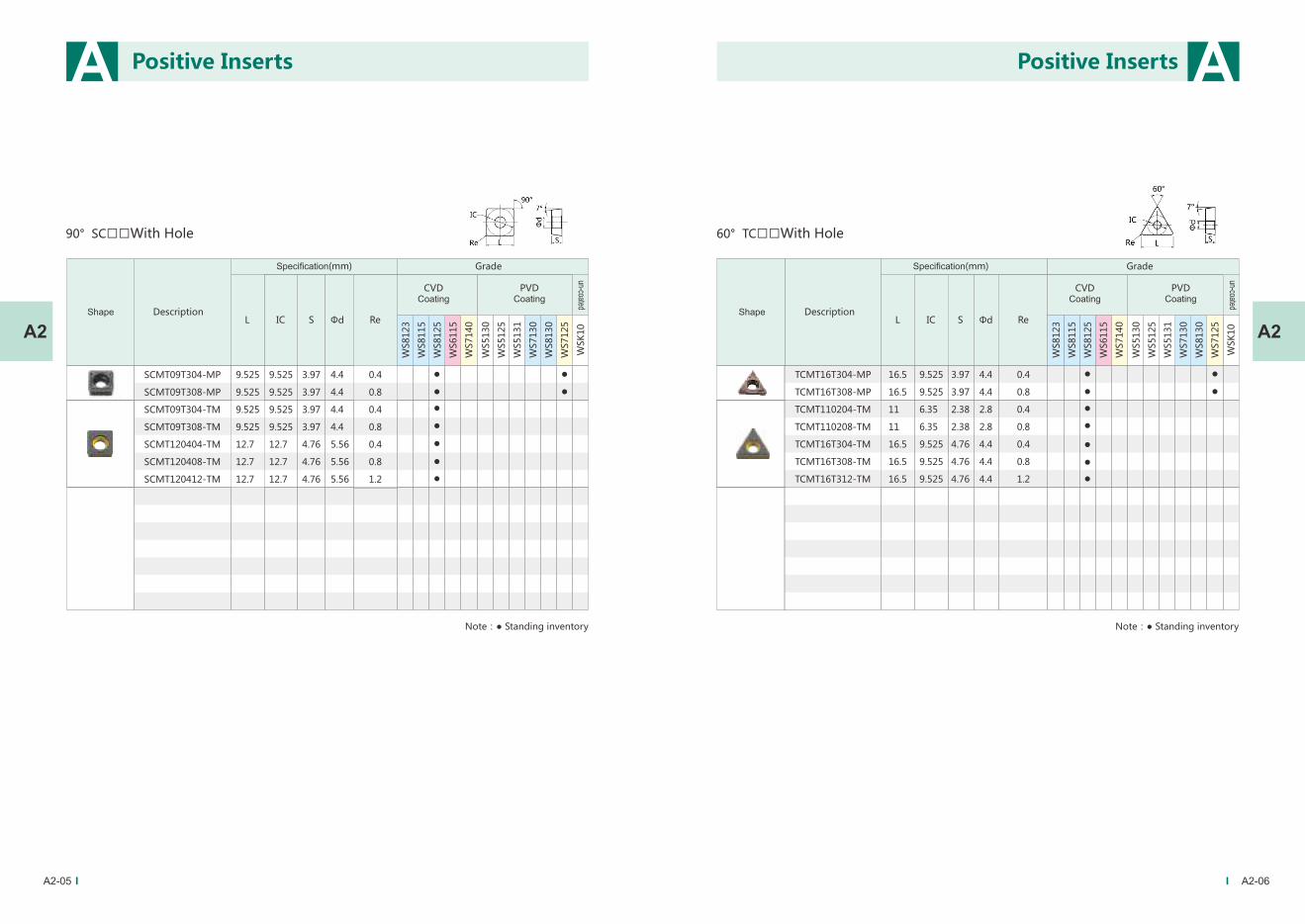
A2-05
A A
A2-06
A2A2
60° TC□□With Hole
L S Φd IC Re
TCMT16T304-MP
TCMT16T308-MP
TCMT110204-TM
TCMT110208-TM
TCMT16T304-TM
TCMT16T308-TM
TCMT16T312-TM
16.5
16.5
11
11
16.5
16.5
16.5
3.97
3.97
2.38
2.38
4.76
4.76
4.76
4.4
4.4
2.8
2.8
4.4
4.4
4.4
0.4
0.8
0.4
0.8
0.4
0.8
1.2
9.525
9.525
6.35
6.35
9.525
9.525
9.525
WS5130
WS5125
WS5131
WS7130
WS8130
WS7125
WSK
10
WS8123
WS8115
WS8125
WS6115
WS7140
90° SC□□With Hole
L S Φd IC Re
SCMT09T304-MP
SCMT09T308-MP
SCMT09T304-TM
SCMT09T308-TM
SCMT120404-TM
SCMT120408-TM
SCMT120412-TM
9.525
9.525
9.525
9.525
12.7
12.7
12.7
3.97
3.97
3.97
3.97
4.76
4.76
4.76
4.4
4.4
4.4
4.4
5.56
5.56
5.56
0.4
0.8
0.4
0.8
0.4
0.8
1.2
9.525
9.525
9.525
9.525
12.7
12.7
12.7W
S5130
WS5125
WS5131
WS7130
WS8130
WS7125
WSK
10
WS8123
WS8115
WS8125
WS6115
WS7140
Specification(mm)
DescriptionShape
CVDCoating
PVDCoating
un-coated
GradeSpecification(mm)
DescriptionShape
CVDCoating
PVDCoating
un-coated
Grade
Positive InsertsPositive Inserts
Note:● Standing inventory Note:● Standing inventory
Page 27
A2-07
A
A2
60° V□□□With Hole
L S Φd IC Re
WS5130
WS5125
WS5131
WS7130
WS8130
WS7125
WSK
10
WS8123
WS8115
WS8125
WS6115
WS7140
VBMT110304-TM
VBMT110308-TM
VBMT160404-TM
VBMT160408-TM
VBMT160412-TM
11.1
11.1
16.6
16.6
16.6
6.35
6.35
9.525
9.525
9.525
3.18
3.18
4.76
4.76
4.76
2.8
2.8
3.81
3.81
3.81
0.4
0.8
0.4
0.8
1.2
Positive Inserts
Specification(mm)
DescriptionShape
CVDCoating
PVDCoating
un-coated
Grade
Note:● Standing inventory
VCMT110304-TM
VCMT110308-TM
VCMT160404-TM
VCMT160408-TM
VCMT160412-TM
11.1
11.1
16.6
16.6
16.6
6.35
6.35
9.525
9.525
9.525
3.18
3.18
4.76
4.76
4.76
2.8
2.8
3.81
3.81
3.81
0.4
0.8
0.4
0.8
1.2
7
7
7
7
7
5
5
5
5
5
α
Reα
IC
Page 28
A3-03
L S Φd IC
WS5130
WS5125
WS5131
WS7130
WS8130
WS7125
WSK
10
WS8123
WS8115
WS8125
WS6115
WS7140
Re
80° CC□□With Hole
CCGT060202-AK
CCGT060204-AK
CCGT09T304-AK
CCGT09T308-AK
CCGT120404-AK
CCGT120408-AK
6.4
6.4
9.7
9.7
12.9
12.9
2.38
2.38
3.97
3.97
4.76
4.76
2.80
2.80
4.40
4.40
5.56
5.56
0.2
0.4
0.4
0.8
0.4
0.8
6.35
6.35
9.525
9.525
12.7
12.7
For Aluminum
IC
Re
A
A3
A Aluminum Inserts
A3-02
A3
L S Φd IC
WS5130
WS5125
WS5131
WS7130
WS8130
WS7125
WSK
10
WS8123
WS8115
WS8125
WS6115
WS7140
Re
55° DC□□With Hole
For Aluminum
DCGT070202-AK
DCGT070204-AK
DCGT11T302-AK
DCGT11T304-AK
7.8
7.8
11.6
11.6
2.38
2.38
3.97
3.97
2.80
2.80
4.40
4.40
0.2
0.4
0.2
0.4
6.35
6.35
9.525
9.525
IC
Re
Series
Specification(mm)
DescriptionShape
CVDCoating
PVDCoating
un-coated
GradeSpecification(mm)
DescriptionShape
CVDCoating
PVDCoating
un-coated
Grade
Note:● Standing inventory Note:● Standing inventory
Aluminum Inserts
Page 29
A3-04 A3-05
L S Φd IC
WS5130
WS5125
WS5131
WS7130
WS8130
WS7125
WSK
10
WS8123
WS8115
WS8125
WS6115
WS7140
Re
60° TC□□With Hole
For Aluminum
TCGT090204-AK
TCGT110204-AK
TCGT16T304-AK
9.7
11.0
16.5
2.38
2.38
3.97
2.80
2.80
4.40
0.4
0.4
0.4
5.56
6.35
9.525
IC
Re
A3
A A
A3
L S Φd IC
WS5130
WS5125
WS5131
WS7130
WS8130
WS7125
WSK
10
WS8123
WS8115
WS8125
WS6115
WS7140
35° VC□□With Hole
For Aluminum
VCGT110302-AK
VCGT110304-AK
VCGT160402-AK
VCGT160404-AK
VCGT160408-AK
VBGT160402-AK
VBGT160404-AK
VBGT160408-AK
11.0
11.0
16.5
16.5
16.5
16.5
16.5
16.5
3.18
3.18
4.76
4.76
4.76
4.76
4.76
4.76
2.80
2.80
4.40
4.40
4.40
4.40
4.40
4.40
0.2
0.4
0.2
0.4
0.8
0.2
0.4
0.8
6.35
6.35
9.525
9.525
9.525
9.525
9.525
9.525
Reα
Re α
7
7
7
7
7
5
5
5
Specification(mm)
DescriptionShape
CVDCoating
PVDCoating
un-coated
GradeSpecification(mm)
DescriptionShape
CVDCoating
PVDCoating
un-coated
Grade
Note:● Standing inventory Note:● Standing inventory
Aluminum Inserts Aluminum Inserts
IC
Page 30
The Explaination of Grooving and Parting
QC M B 30 04
A4-02
A4
AGrooving and Parting Insert
CodeWidth
Code Standard
The grade of accruacy The width of edge
Code Code CodeType
Parting
Grooving
Profiling
Cutting edgeInserts shape
Edge
Single
Double
Triple
Corner radius
Radius
Compiled
Code
(mm)
Adding code
The manufacturer
accoding to Chip-
breaker or other
features to make
the code,you can
ignore this code.
Page 31
A4-03 A4-04
A4
A A
A4
Features of grooving inserts
◆ A type of general machining cutting insert with multifunction which can be used for grooving and turning.
Improved 3D chipbreaker achieved effective control of grooving. Maximum decease the cutting resistance and machining
vibration.
◆ High toughness cutting edge reduce the chipping possibility of cutting nose at unstable machining conditions. Suitable
for interrupted cut and vibration machining.
◆ The combination of wear-resistance and toughness that improved the service life and machining reliability.
Processing method
Cylindrical cutter machining Cylindrical grooving machining
Internal grooving machiningFace grooving machining
Features of chip-breaker
Chip-breaker M:Satisfied cutting, grooving, turning and other processing needs, the cutting process
becomes light, chip more smooth, to achieve the ideal processing surface quality.
Chip-breaker G:mainly used for cutting applications.Special chip-breaker design makes cutting narrow and
improves cutting flow control.
Chip-breaker T:The special back face structure reduces the cutting resistance by 20 %,reducing noise and
shakes,improving the quality of face.The special cutting edge design makes the chip breaking effect
better,it can machining by transverse section.
For Grooving and Parting
QCMB2002-M
QCMB2502-M
QCMB3004-M
QCMB4004-M
QCMB5008-M
QCMB6008-M
QCMB15015-G
QCMB2002-G
QCMB2502-G
QCMB3003-G
QCMB2002-T
QCMB3004-T
QCMB4004-T
QCMB2002
QCMB3004
QCMB4004
QCMB5008
16
18.5
21
21
26
26
16
16
18.5
21
16
21
21
16
21
21
26
3.50
3.90
4.76
4.76
5.80
5.90
3.50
3.5
3.85
4.8
3.55
4.86
4.86
3.55
4.86
4.86
5.80
0.2
0.2
0.4
0.4
0.8
0.8
0.15
0.2
0.2
0.3
0.2
0.4
0.4
0.2
0.4
0.4
0.8
8°
8°
8°
8°
8°
8°
8.5°
7.5°
8.5°
7.5°
7.5°
7.5°
7.5°
7.5°
7.5°
7.5°
7.5°
L T ReS a
2.0
2.5
3.0
4.0
5.0
6.0
1.5
2.0
2.5
3.0
2.0
3.0
4.0
2.0
3.0
4.0
5.0
WS5130
WS5125
WS5131
WS7130
WS8130
WS7125
WSK
10
WS8123
WS8115
WS8125
WS6115
WS7140
Series
Specification(mm)
DescriptionShape
CVDCoating
PVDCoating
un-coated
Grade
Grooving and Parting InsertGrooving and Parting Insert
Page 32
A4-05 A4-06
S TL Re
WS5130
WS5125
WS5131
WS7130
WS8130
WS7125
WSK
10
WS8123
WS8115
WS8125
WS6115
WS7140
QPMB2010-M
QPMB3015-M
QPMB4020-M
QPMB5025-M
16
21
21
26
2.0
3.0
4.0
5.0
3.5
4.8
4.8
5.8
1.0
1.5
2.0
2.5
7°
7°
7°
7°
a
A4
A A
A4
Application Case
Grooving flange end face
Stainless steel SUS304
Continuous turning end face
QCMB4004-M WS7125
Vc=147.2m/min,f=0.04mm/r
Hardstone:352 pieces/cutting edge Brand M:218 pieces/cutting edge
Grooving end turning
Casting stainless steel
Continuous grooving, external turning
QCMB3004-M WS7125
Vc=120m/min,f=0.1mm/r
Hardstone:11 pieces/cutting edge
Brand C:10 pieces/cutting edge
stainless steel SUS304
Continuous turning end face
QCMB3004-T WS7125
Vc=130m/min,f=0.05mm/r
Hardstone: 1300 pieces /cutting edge
Brand C:1100 pieces/ cutting edge
Grooving seal groove end face
Specification(mm)
DescriptionShape
CVDCoating
PVDCoating
un-coated
Grade Workpiece
Machining way
Inserts
Machining parameter
Result of cutting
Workpiece
Machining way
Inserts
Machining parameter
Result of cutting
Workpiece
Machining way
Inserts
Machining parameter
Result of cutting
Grooving and Parting InsertGrooving and Parting Insert
Page 33
R
16
22
E
I
ISO
ISO
UN
W
BSPT
NPT
Unified thread
Whitworth thread
British standard taper
piper thread
American standard
taper piper thread
E16 150
A5-02
A5
A Threading Inserts
Insert size(Inch)
CodeDiameter
of ICCode
Left
Right
Direction
Cutting direction
Cutting types
Code Types
External
threading
inserts
Internal
threading
inserts
Thread pitch
Full profile
V profile
Profile
Code Types
ISO metric 60°thread
Page 34
Internal threading machiningright thread
Internal threading machiningleft thread
External threading machiningright thread
External threading machiningleft thread
Processing mode of thread cutting inserts
◆ Pressed by high precision mould which ensure the high accuracy of tooth profiles and excellent quality of cutting edge.
◆ Strict measurement control which narrow the size difference between inserts and keep the consistency.
◆ Special process technique for cutting edge makes small circular nose treatment more professional and reasonable.
◆ The insert with chip breaker improves the capacity of iron processing, possessing the excellent processing stability.
◆ WS5125, the specially developed for threading inserts, ensuring effectively resistance of plastic deformation and abrasion
in machining.
Features of threading inserts Feed mode of thread cutting inserts
◆ Radial machining, the most common way of machining.
◆ The cutting edge is relative sharp with good toughness material, suitable for fine pitch
thread
cutting and meet the small cut deep machining requirement.
◆ Due to different workpiece being processed, the V-type chip is difficult to control in
machining.
◆ The longer the interface of cutting chips on left and right side, the heavier the cutting load
produced. Thus more easier cause the vibration.
Radial in-feed
◆ With more cutting depth, the cutting edge bear less pressure. Thus provide a stable
working
condition, recommended for coarse pitch thread cutting.
◆ Flank in-feed is conductive to chip discharging.
◆ The right side cutting edge is easy to wear, so it is easier to discharge in the same
direction.
Flank in-feed
◆ The improved method of flank in-feed from the side along the cutting tooth.
◆ The consistency chip removal direction provides an easy way for discharging.
◆ Reduce the abrasion of right side flank, recommended for double-edged thread
machining.
◆ The right side cutting edge also involved in a certain cutting depth, completely
eradicate the
phenomenon of zero cutting depth. More stable in cutting machining.
Improved flank in-feed
◆ Alternation use of cutting edge which well distribute the wear for left and right
side’s flank, extending
the tool’s life.
◆ Chips are flowing from both of right and left, good chips removal.
◆ Recommended for coarse pitch thread cutting.
Alternation flank in-feed
A5-03 A5-04
A A
A5A5
Threading Inserts Threading Inserts
Page 35
A A
A5-05 A5-06
A5A5
For threading
55° Whitworth thread
16ER11W
16ER14W
16ER19W
16IR11W
16IR14W
16IR19W
11
14
19
11
14
19
1.5
1.2
1.0
1.5
1.2
1.0
3.52
3.52
3.52
3.52
3.52
3.52
4
4
4
4
4
4
9.525
9.525
9.525
9.525
9.525
9.525
0.3
0.23
0.17
0.3
0.23
0.17
Th
read
pitc
h
WS5130
WS5125
WS5131
WS7130
WS8130
WS7125
WSK
10
WS8123
WS8115
WS8125
WS6115
WS7140
For threading
60° ISO metric thread
S T Φd IC Re
55
55
55
55
55
55
WS5130
WS5125
WS5131
WS7130
WS8130
WS7125
WSK
10
WS8123
WS8115
WS8125
WS6115
WS7140S T Φd IC Re
60
60
60
60
60
60
60
60
θ
16ER150ISO
16ER200ISO
16ER250ISO
16ER300ISO
16IR150ISO
16IR200ISO
16IR250ISO
16IR300ISO
1.5
2.0
2.5
3.0
1.5
2.0
2.5
3.0
1.0
1.3
1.5
1.6
1.0
1.3
1.5
1.5
3.52
3.52
3.52
3.52
3.52
3.52
3.52
3.52
4
4
4
4
4
4
4
4
9.525
9.525
9.525
9.525
9.525
9.525
9.525
9.525
0.2
0.26
0.33
0.44
0.1
0.13
0.17
0.22
θ
Series
Shape Description
Specification(mm) Grade
CVDCoating
PVDCoating
un-coated Threading Inserts Threading Inserts
Specification(mm)
DescriptionShape
CVDCoating
PVDCoating
un-coated
Grade
Th
read
pitc
h
Page 36
British standard
taper piper thread
16ER11BSPT
16ER14BSPT
16ER19BSPT
16IR11BSPT
16IR14BSPT
16IR19BSPT
11
14
19
11
14
19
1.5
1.2
0.9
1.5
1.2
0.9
3.52
3.52
3.52
3.52
3.52
3.52
0.32
0.23
0.19
0.32
0.23
0.19
9.525
9.525
9.525
9.525
9.525
9.525
WS5130
WS5125
WS5131
WS7130
WS8130
WS7125
WSK
10
WS8123
WS8115
WS8125
WS6115
WS7140
4
4
4
4
4
4
55
55
55
55
55
55
IC S T Re Φd θ
General pitch thread
16ERAG55
16ERAG60
16IRAG55
16IRAG60
0.5-3.0
0.5-3.0
0.5-3.0
0.5-3.0
1.7
1.7
1.7
1.7
3.52
3.52
3.52
3.52
0.06
0.07
0.06
0.076
9.525
9.525
9.525
9.525
WS5130
WS5125
WS5131
WS7130
WS8130
WS7125
WSK
10
WS8123
WS8115
WS8125
WS6115
WS7140
4
4
4
4
55
60
55
60
IC S T Re Φd θ
A5-07 A5-08
A A
A5A5
Threading Inserts Threading Inserts
Series
Thread
pitch
Specification(mm)
DescriptionShape
CVDCoating
PVDCoating
un-coated
Grade
Thread
pitch
Specification(mm)
DescriptionShape
CVDCoating
PVDCoating
un-coated
Grade
Page 37
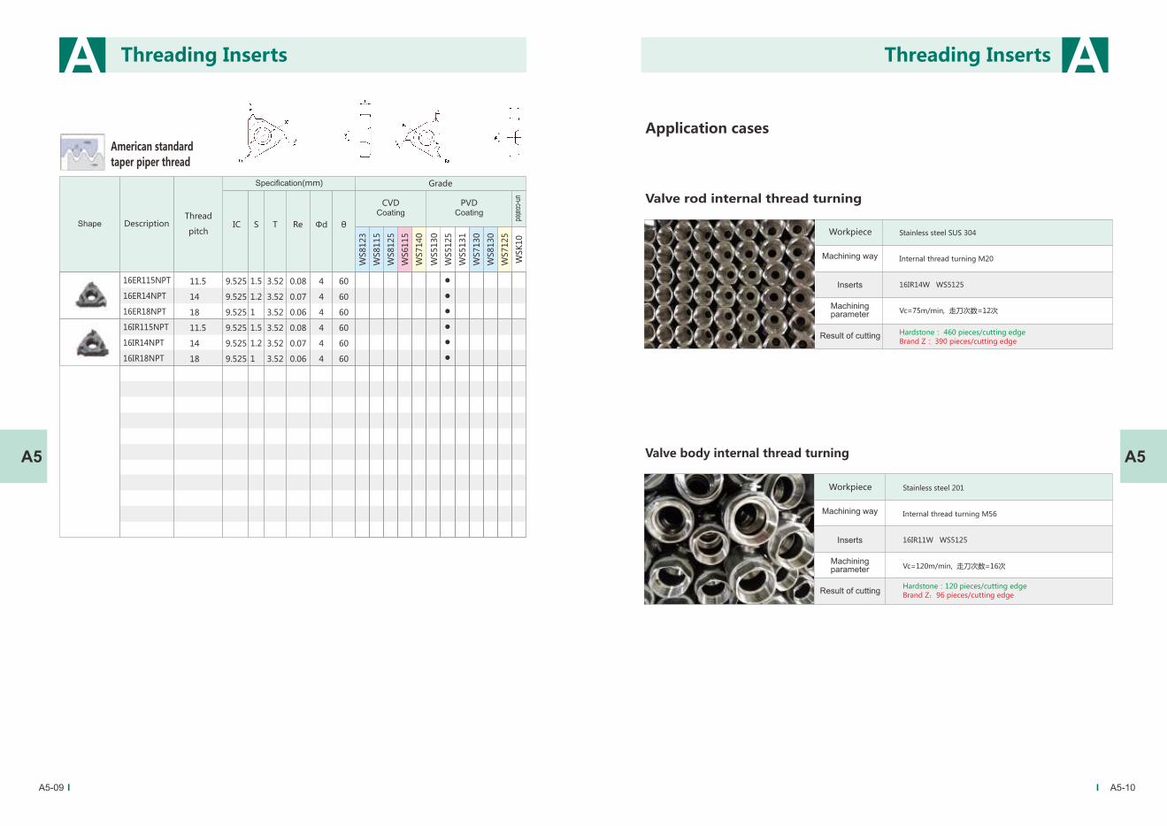
A5-09 A5-10
A A
A5A5
American standard
taper piper thread
16ER115NPT
16ER14NPT
16ER18NPT
16IR115NPT
16IR14NPT
16IR18NPT
11.5
14
18
11.5
14
18
1.5
1.2
1
1.5
1.2
1
3.52
3.52
3.52
3.52
3.52
3.52
0.08
0.07
0.06
0.08
0.07
0.06
9.525
9.525
9.525
9.525
9.525
9.525
WS5130
WS5125
WS5131
WS7130
WS8130
WS7125
WSK
10
WS8123
WS8115
WS8125
WS6115
WS7140
4
4
4
4
4
4
60
60
60
60
60
60
IC S T Re Φd θ
Application cases
Stainless steel SUS 304
Internal thread turning M20
16IR14W WS5125
Vc=75m/min, 走刀次数=12次
Hardstone: 460 pieces/cutting edge
Brand Z: 390 pieces/cutting edge
Valve rod internal thread turning
Stainless steel 201
Internal thread turning M56
16IR11W WS5125
Vc=120m/min, 走刀次数=16次
Hardstone:120 pieces/cutting edge
Brand Z:96 pieces/cutting edge
Valve body internal thread turning
Threading Inserts Threading Inserts
Workpiece
Machining way
Inserts
Machining parameter
Result of cutting
Workpiece
Machining way
Inserts
Machining parameter
Result of cutting
Thread
pitch
Specification(mm)
DescriptionShape
CVDCoating
PVDCoating
un-coated
Grade
Page 38
A5-11 A5-12
A A
A5A5
Pipe joint internal thread turning
Stainless steel SUS201
Internal thread turning
16IR11W WS5125
Vc=93.3m/min, Cutting times: 17 times
WS5125
Brand Z
Comparison result of cutting 50 pcs parts:Hardstone:slight wear Brand Z:severe wear
Valve deck internal thread turning
Stainless steel 201
Internal thread turning M45
16IR11W WS5125
Vc=98.9m/min , cutting times:16 times,
Comparison result of cutting 70 pcs parts:
Hardstone: slight wear Brand Z:severe wear
WS5125
90
94
98
102
106
110
Qu
an
tity
Hardstone Brand B
Application Case Comparison No.1
Application Case Comparison No.2
100
200
300
400
500
Qu
an
tity
0
Threading Inserts Threading Inserts
Workpiece
Machining way
Inserts
Machining parameter
Result of cutting
Workpiece
Machining way
Inserts
Machining parameter
Result of cutting
Brand Z
Workpiece material:Stainless steel 201 Cutter bar:
SNR2525K16
Inserts type:16IR11W
Cutting parameters
n = 600r/min , cutting times:16 times, Vc=103m/min
Result of cutting
Hardstone A continuous machining 108 pieces,normal wear
Brand B continuous machining 98 pieces,slight chipping.
Workpiece material:Stainless steel 304 Cutter bar:
SNR2020K16
Inserts type:16IR14W
Cutting parameters
n = 900r/min , cutting times:11 times, Vc=85m/min
Result of cutting
Hardstone A continuous machining 440 pieces,normal wear
Brand B continuous machining 310 pieces,severe wear
Hardstone Brand B
Page 39
Milling Insert
B1 General Milling Insert
B2 Heavy Milling Insert
B-03 — 04
B1-01 — 02
B1-03
B1-04
B1-05 — 19
Overview
B1-20 — 25
B2-02 — 03
B2-04
B2-05 — 22
B2-23
The Explanation Of Grade
The Explanation Of Specification
Series
Feature
Application Case
Overview
The Explanation Of Specification
Series
Application Case
Page 40
The Explanation Of Grade
45403530252015100501
P20~P35
M20~M35
K20~K35
P35~P45
M35~M45
ISO
It is suitable for the general milling of
steel, stainless steel, cast iron and other
materials, especially in the range of
steel HRC30-50.
It is the firstly grade of stainless steel for milling. With different chipbreaker types, it can meet the requirements of roughing and finishing milling of all kinds of stainless steel and titanium alloys, and has good stability and safety.
It is a medium and low speed of heavy milling for stainless steel and steel.
It is a general machining for heavy milling of steel.
AlTiNWS5130
WS7130
WS7140
WS8130
PVDGray
Black
PVD Gray
CVDgold
-yellow
PVD
AlCrN
TiN+MT-TiCN+Al2O3+TiN
AlTiNP25~P35
M25~M35
P35~P45
M35~M45
B-03 B-04
B B
BB
Milling Inserts
AlTiN+TiNPVDWS5131
Grade
Coating Strucuture
Pictures Component RangeCoating
ColorCoating
Way
Thin
Thick-
Thin
Thin
Thin
Gray
Black
gold
-yellow
Wear Resistanoe Toughness
Application
Milling Inserts
Page 41
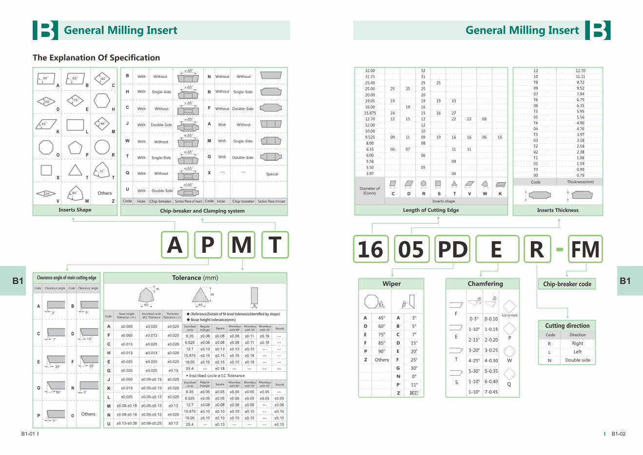
The Explanation Of Specification
ଽ్ଽ్ჵ
A TP M R
32.00 32
31.75 31
25.40 25 25
25.00 25 25 25
20.00 20
19.05 19 19 19 33
16.00 19 16
15.875 16 15 16 27
12.70 12 15 12 22 22 08
12.00 12
10.00 10
9.525 09 11 09 19 16 16 06 16
8.00 08
6.35 06 07 11 11
6.00 06
5.56 09
5.50 05
3.97 06
12 12.70
10 11.11
T9 9.72
09 9.52
07 7.94
T6 6.75
06 6.35
T5 5.95
05 5.56
T4 4.96
04 4.76
T3 3.97
03 3.18
T2 2.58
02 2.38
T1 1.98
01 1.59
T0 0.99
00 0.79
16 05 PD FME
Kr α°
A o45 A o3
D o60 B o5
E o75 C o7
F o85 D o15
P o90 E o20
Z F o25
G o30
N o0
P o11
Z 其它
R Right
L Left
N Double side
F
E
T
S
α° b
K
P
W
Q
(or no mark)o0-5 0-0.10
o1-10 1-0.15
o2-15 2-0.20
o3-20 3-0.25
o4-25 4-0.30
o5-30 5-0.35
o1-10 6-0.40
o1-10 7-0.45
ΦD ΦD
Wiper Chamfering
Others
B1-01 B1-02
B B
B1B1
General Milling Insert General Milling Insert
Inserts Shape Chip-breaker and Clamping system
With
With
With
With
With
With
With
With
Code Hole Chip-breaker Section Plane of insert Code Hole Chip-breaker Section Plane of insert
Without
Single-Side
Without
Double-Side
Single-Side
Without
Without
Double-Side
Without
Without
Without
With
With
With
Without
Single-Side
Double-Side
Without
Single-Side
Double-Side
Special
Diameter of
IC(mm)
Inserts shape
Length of Cutting Edge
Code Thickness(mm)
Inserts Thickness
Clearance angle of main cutting edge
Code Clearance angle Code Clearance angle
Tolerance (mm)
Others
CodeNose height
Tolerance(m)
Inscribed circle
øI.C Tolerance
Thickness
Tolerance(s)◆�(Reference)Details�of�M-level�tolerance(Idertifled�by�shape)
◆�Nose�height�tolerance(mm)
Inscribed
circle
Regular
triangleSquare
Rhombus
with 80°
Rhombus
with 55°
Rhombus
with 35°Round
◆ Inscribed circle ø I.C Tolerance
Inscribed
circleSquare
Rhombus
with 80°
Rhombus
with 55°
Rhombus
with 35°Round
Regular
triangle
Chip-breaker code
Cutting direction
Code Direction
Others
Page 42
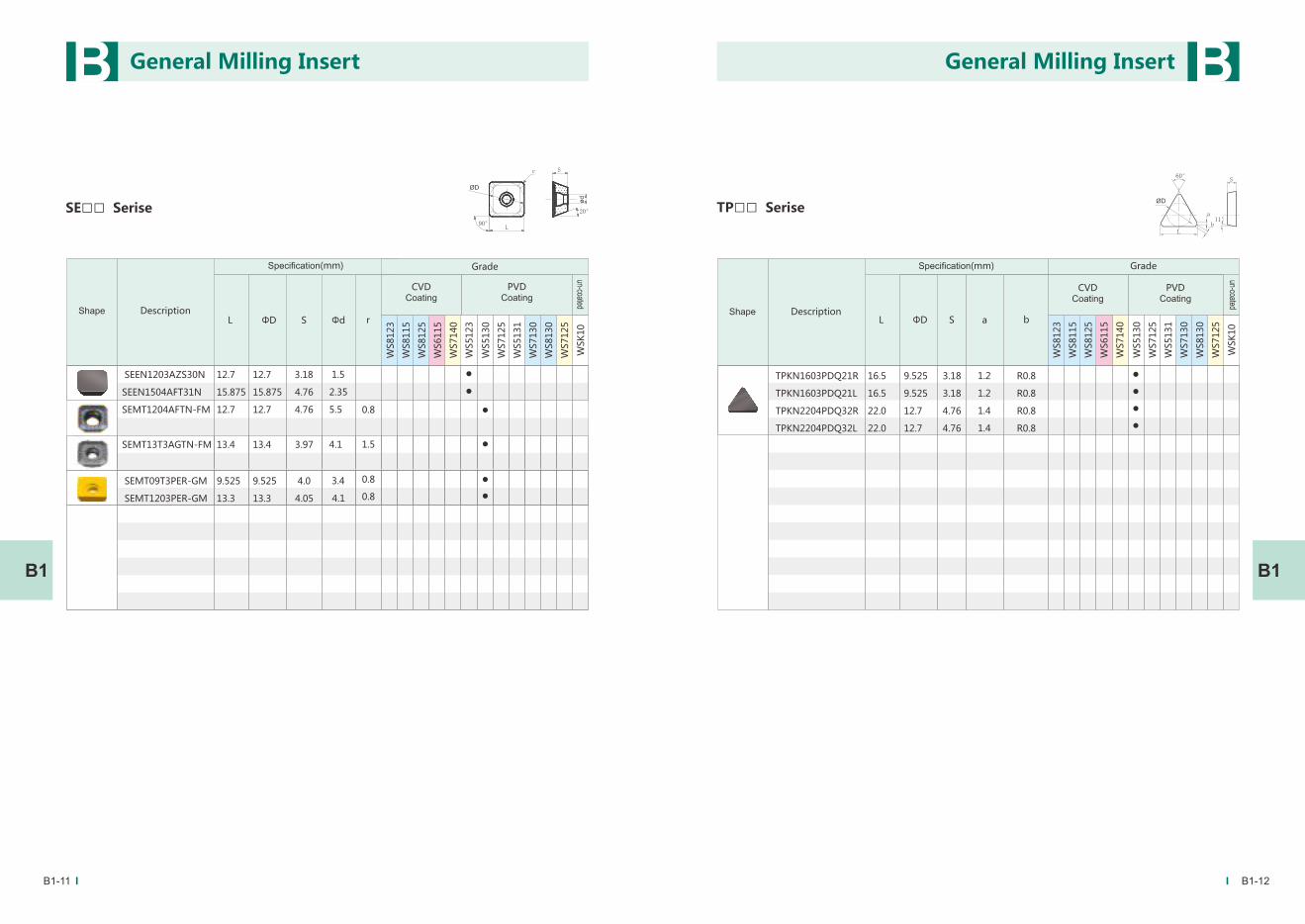
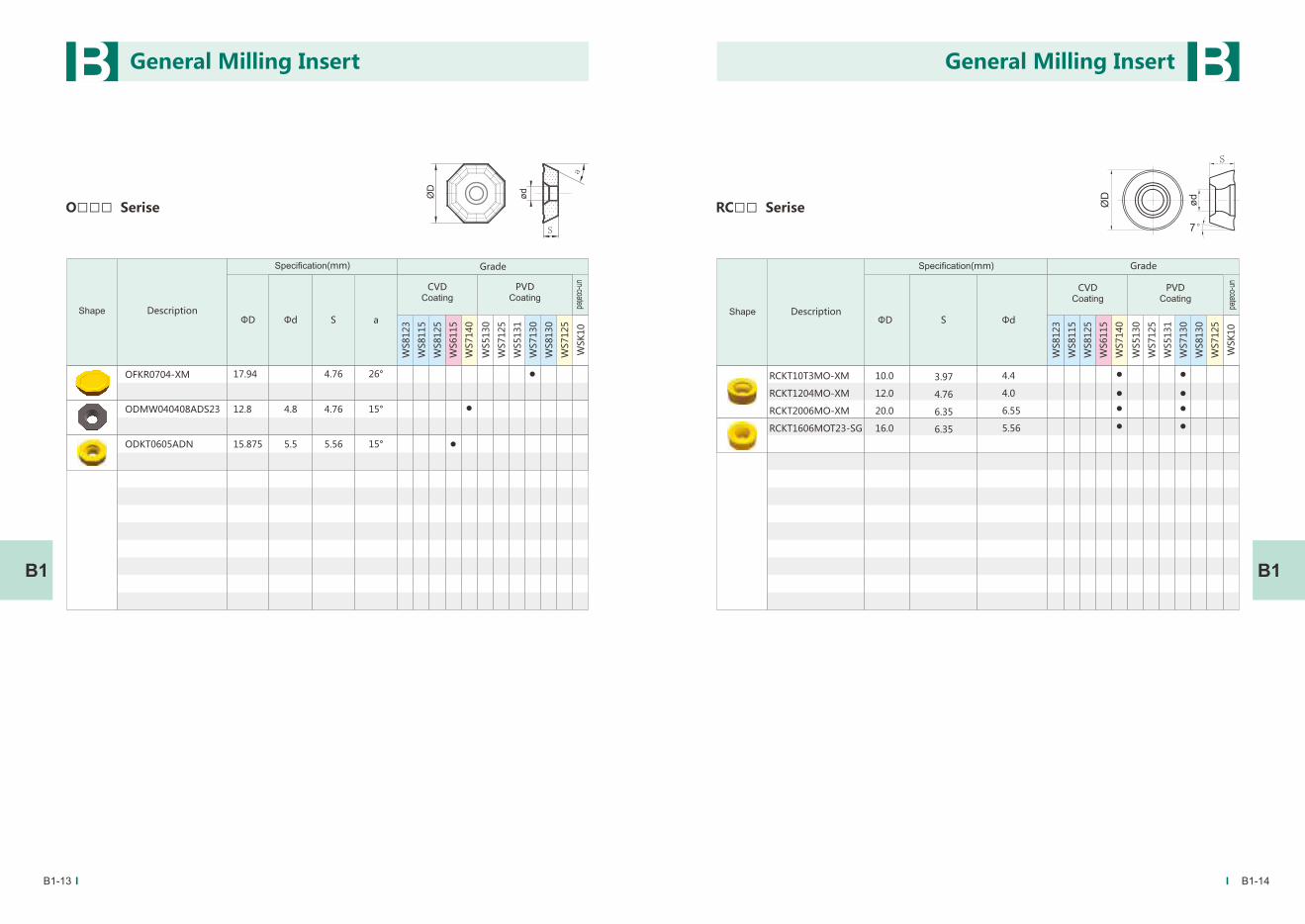
SEET *-GF/GM/GR SEET *-ZF/ZM/ZR SEEN * OFKR *-XM ODMW* ODKT*
APMT*-FM APMT*-MM/XM SPMT*-XM7 SPHX* SEMT*-GM TPKN*
RCKT *-XM RCKT *-SG RPMT*-FMRDMW*
WDMW* WPMT*
SPKR *-YR
45°Inserts for face milling
75°Inserts for face milling
Inserts for square shoulder milling
Inserts for profile milling
Inserts for high feed milling
Overview
B1-03 B1-04
-FM RPMT *-D57
B B
B1B1
Milling inserts’Features
Schematic diagram of cutting pocesses
Face milling Shoulder milling
◆ Design with double clearance angle and special treatment on its cutting edge?and tool nose. High dimensional accuracy, fine
and smooth surface.
◆ Using fine cemented carbide substrate with unique process and excellent coating, which achieved the combination of
hardness, toughness and higher red hardness.
◆ According to the different hardness of mould workpiece , evaluate the service life of cutting tools accurately. In this way,
automatic and unmanned processing is realized and raises the production efficiency.
◆ Suitable for processing of face milling,shoulder milling,cavity milling,ramp machining ,profile milling, etc.
◆ Well solved the difficulty of tools selection and replacement, thus reducing tools inventory costs.
◆ Versatility,good stability, long service life, high cost-effective. machining ,profile milling, etc.
SEMT
RCKT-FM
SDMW SDMT
SPKN*
General Milling Insert General Milling Insert
Cavity milling Slot milling
Helical interpolation milling Ramp milling Plane milling Profile milling
Page 43
B1-05 B1-06
Insert for helical milling with end tooth
AP□□ Serise
L S Φd
WS5130
WS7125
WS5131
WS7130
WS8130
WS7125
WSK
10
WS8123
WS8115
WS8125
WS6115
WS7140W
ød
11°
W
L 92°
APMT150412-MM
APMT150412-XM7
APHX1504
16.33
16.33
16.33
12.7
12.7
12.7
5.4
5.4
5.4
4.76
4.76
4.76
S
B B
B1B1
L 1 L2
WS5130
WS5125
WS5131
WS7130
WS8130
WS7125
WSK
10
WS8123
WS8115
WS8125
WS6115
WS7140Re D2 T D1
For mould milling
11°
APMT1135PDER-FM
APMT1604PDER-FM
APMT1605PDER-FM
RPMT08T2M0-FM
RPMT10T3MO-FM
RPMT1003MO-FM
RPMT1204MO-FM
RPMW1003MO-FM
RDMW10T3MO-FM
RDMW1204MO-FM
RDMW1605MO-FM
RCKT10T3MO-FM
RCKT1204MO-FM
RCKT1606MO-FM
RCKT2006MO-FM
8
10
10
12
10
10
12
16
10
12
16
20
3.5
4.76
5.22
2.78
3.97
3.18
4.76
3.18
3.97
4.76
5.56
3.97
4.76
6.35
6.35
2.8
4.4
4.5
3.5
4.5
4.5
4.5
4.5
4.5
5.5
5.5
4.4
4.4
5.5
6.55
11.3
17.25
17.42
6.25
9.22
9.33
0.8
0.8
0.8
General Milling Insert General Milling Insert
Series
Specification(mm)
DescriptionShape
CVDCoating
PVDCoating
un-coated
GradeSpecification(mm)
DescriptionShape
CVDCoating
PVDCoating
un-coated
Grade
Page 44
B1-07 B1-08
B B
B1B1
Series
SD□□ Serise Insert for roughing feed
WS5130
WS7125
WS5131
WS7130
WS8130
WS7125
WSK
10
WS8123
WS8115
WS8125
WS6115
WS7140
L ΦD S Φd R
SDMW1205ZTN
SDMW1505ZTN
SDMT1205ZTN-FM
SDMT1505ZTN-FM
3
0.8
3
0.8
4.6
5.5
4.6
5.5
12.7
15.875
12.7
15.875
5.56
5.56
5.56
5.56
12.7
15.875
12.7
15.875
SP□□ Serise
L S a
WS5130
WS7125
WS5131
WS7130
WS8130
WS7125
WSK
10
WS8123
WS8115
WS8125
WS6115
WS7140 ΦD b
SPKN1504EDFR
SPKN1504EDFL
SPKN1504EDS32R
SPKN1504EDS32L
15.875
15.875
15.875
15.875
4.76
4.76
4.76
4.76
15.875
15.875
15.875
15.875
1.4
1.4
R1.6
1.2
1.0
1.0
1.2
R1.6
General Milling Insert General Milling Insert
Specification(mm)
DescriptionShape
CVDCoating
PVDCoating
un-coated
GradeSpecification(mm)
DescriptionShape
CVDCoating
PVDCoating
un-coated
Grade
Page 45
SP□□ Serise
L S a
WS5130
WS7125
WS5131
WS7130
WS8130
WS7125
WSK
10
WS8123
WS8115
WS8125
WS6115
WS7140 ΦD b
SPKR1504EDR-YR
SPKR1504EDL-YR
15.875
15.875
4.76
4.76
15.875
15.875
1.0
1.0
1.4
1.4
ØD
S
75°
L
11°
ab
B1-09 B1-10
B B
B1B1
Insert for helical milling with peripheral tooth
SP□□ Serise
L S
WS5130
WS7125
WS5131
WS7130
WS8130
WS7125
WSK
10
WS8123
WS8115
WS8125
WS6115
WS7140 Φd r
SPMT120408-MM
SPMT120408-XM7
SPHX120408
12.7
12.7
12.7
4.76
4.76
4.76
12.7
12.7
12.7
5.5
5.5
5.5
0.8
0.8
0.8
ΦD
General Milling Insert General Milling Insert
Specification(mm)
DescriptionShape
CVDCoating
PVDCoating
un-coated
GradeSpecification(mm)
DescriptionShape
CVDCoating
PVDCoating
un-coated
Grade
r
Page 46
B1-11 B1-12
B B
B1B1
SE□□ Serise
L S
WS5130
WS7125
WS5131
WS7130
WS8130
WS7125
WSK
10
ΦD r
SEMT09T3PER-GM
SEMT1203PER-GM
SEEN1203AZS30N
SEEN1504AFT31N
SEMT1204AFTN-FM
SEMT13T3AGTN-FM
9.525
13.3
12.7
15.875
12.7
13.4
4.0
4.05
3.18
4.76
4.76
3.97
9.525
13.3
12.7
15.875
12.7
13.4
3.4
4.1
1.5
2.35
5.5
4.1
ØD
ød
90°
20°
Sr
L
Φd
WS8123
WS8115
WS8125
WS6115
WS7140
WS5123
0.8
0.8
0.8
1.5
TP□□ Serise
L S
WS5130
WS7125
WS5131
WS7130
WS8130
WS7125
WSK
10
WS8123
WS8115
WS8125
WS6115
WS7140 ΦD b
TPKN1603PDQ21R
TPKN1603PDQ21L
TPKN2204PDQ32R
TPKN2204PDQ32L
16.5
16.5
22.0
22.0
3.18
3.18
4.76
4.76
9.525
9.525
12.7
12.7
1.2
1.2
1.4
1.4
R0.8
R0.8
R0.8
R0.8
a
ØD
S
11°
60°
a
bL
General Milling Insert General Milling Insert
Specification(mm)
DescriptionShape
CVDCoating
PVDCoating
un-coated
GradeSpecification(mm)
DescriptionShape
CVDCoating
PVDCoating
un-coated
Grade
Page 47
B1-13 B1-14
B B
B1B1
O□□□ Serise
S
WS5130
WS7125
WS5131
WS7130
WS8130
WS7125
WSK
10
WS8123
WS8115
WS8125
WS6115
WS7140 Φd
ODMW040408ADS23
ODKT0605ADN
12.8
15.875
4.76
5.56
4.8
5.5
15°
15°
a
ØD
ød
S
a
ΦD
RC□□ Serise
S Φd
WS5130
WS7125
WS5131
WS7130
WS8130
WS7125
WSK
10
WS8123
WS8115
WS8125
WS6115
WS7140
RCKT10T3MO-XM
RCKT1204MO-XM
RCKT2006MO-XM
RCKT1606MOT23-SG
10.0
12.0
20.0
16.0
4.4
4.0
6.55
5.56
3.97
4.76
6.35
6.35
ød
S
7°
ØD
ΦD
OFKR0704-XM 17.94 4.76 26°
General Milling Insert General Milling Insert
Specification(mm)
DescriptionShape
CVDCoating
PVDCoating
un-coated
GradeSpecification(mm)
DescriptionShape
CVDCoating
PVDCoating
un-coated
Grade
Page 48
B1-15 B1-16
B B
B1B1
RP□□ Serise
S
WS5130
WS7125
WS5131
WS7130
WS8130
WS7125
WSK
10
WS8123
WS8115
WS8125
WS6115
WS7140 Φd
RPHX10T3MO-D57
RPHT1204MO-D57
3.97
4.76
10.0
12.0
4.4
4.4
ΦD
ød
S
7°
ØD
WD□□ Serise
S
WS5130
WS7125
WS5131
WS7130
WS8130
WS7125
WSK
10
WS8123
WS8115
WS8125
WS6115
WS7140 Φd
WDMW080520ZTR
WDMT080520ZTR-GM
13.0
13.0
5.0
5.0
5.5
5.5
2.0
2.0
S15°
ØD90°
r
ød
ΦD r
General Milling Insert General Milling Insert
Specification(mm)
DescriptionShape
CVDCoating
PVDCoating
un-coated
GradeSpecification(mm)
DescriptionShape
CVDCoating
PVDCoating
un-coated
Grade
Page 49
B1-17 B1-18
B B
B1B1
WP□□ Serise
S Φd
WS5130
WS7125
WS5131
WS7130
WS8130
WS7125
WSK
10
WS8123
WS8115
WS8125
WS6115
WS7140
WPMT080615ZSR 12.85 6.35 1.55.5
ΦD
S11°
ød
ØD
90°
r
r L S Φd W
WS5130
WS5125
WS5131
WS7130
WS8130
WS7125
WSK
10
WS8123
WS8115
WS8125
WS6115
WS7140
Re
AP□□With Hole
Milling inserts for Aluminium
APGT1135PDFR-G2
APGT1604PDFR-G2
APKT1604PDFR-MA
APKT1604PDFR-MA3
11.25
17.25
16.17
17
3.50
4.76
4.76
5
2.80
4.40
4.40
4.40
6.20
9.25
9.525
9.525
ødW
L11°
83°
S
0.8
0.8
0.2
0.8
Re
General Milling Insert General Milling Insert
Specification(mm)
DescriptionShape
CVDCoating
PVDCoating
un-coated
GradeSpecification(mm)
DescriptionShape
CVDCoating
PVDCoating
un-coated
Grade
Page 50
B1-19
B B
B1-20
B1B1
L S Φd IC
WS5130
WS5125
WS5131
WS7130
WS8130
WS7125
WSK
10
WS8123
WS8115
WS8125
WS6115
WS7140
α
90° SE□□With Hole
Milling inserts for Aluminium
SEHT1204AFFN-X83 12.70 4.76 5.5612.70 1.6
α
◆ C45W commonly known as 45 # steel, Hong Kong named it ace steel. Hardness is range from HB170 to HB220. Has widely application,
and the price is relatively cheap.
◆ Germansy ’40CrMnMo7 is used as pre-hardened plastic mould steel, hardness range from HRC28 to HRC40 .Its advantage is higher
hardness than medium carbon steel and more stable on deformation.
◆ US grade P20 belongs to plastic mould steel, Called 3Cr2Mo in China. This grade steel has uniform hardness range from HRC30 to
HRC42, with good polishing and light etching performance, which suitable for large and medium-sized precision moulds matching
with large die-set. This steel has good machine ability and widely used in plastic moulds.
◆ Pre-hardened plastic mould steel NAK80, delivery hardness from HRC37 to HRC43. Has a good polish and carve ability, good discharge
performance, and commonly used in mirror polishing mould.
◆ 4Cr5MoSiV1, American-standard is H13. Before the heat treatment, hardness range from HRC15 to HRC 20, has excellent high-
temperature strength, wear resistance, toughness and other comprehensive mechanical properties. Good harden ability,small thermal
deformation, and easy for processing, which is suitable for larger size, complex shape mould. Widely used in aluminum, zinc die-casting
mould applications.
◆ The varieties of 7185, 738H, 745H, Nak5, etc. have just accounted for about 15% to 20% in mould applications. The processing of these
kinds is more difficult to machining than 45 # steel which mainly for the mould core and cavity .
Brief introduction of main workpiece materials
Application Case Comparison No.1
Workpiece material:steel 45#
Material hardness: HB200 Holder:φ63x6t
Inserts type:APMT1605PDER-FM
Cutting parameters
S=800rpm f=4800mmpm ap=0.5mm ae=45mm
Result of cutting
Hardstone A processing for 400mins,normal wear
without breakage.Foreign B processing for
370mins,slight chipping。
100
150
200
250
300
400
foreign B Hardstone A
pro
cess
ing
tim
e(
min
)
350
0
30
60
90
120
150
180Application Case Comparison No.2
General Milling Insert General Milling Insert
Specification(mm)
DescriptionShape
CVDCoating
PVDCoating
un-coated
Grade
Workpiece material:P20
Material hardness: HRC30
Holder:φ20x2t
Inserts type:APMT1135PDER-FM
Cutting parameters
S=2200rpm f=2500mmpm ap=0.27mm
Result of cutting
Hardstone A processing for 150mins, normal wear
on flank and rake surface.Foreign B processing
for 130mins, cutting edge slight chipping.
pro
cess
ing
tim
e(
min
)
foreign B Hardstone A
Page 51
B1-21 B1-22
B B
B1B1
Application Cases
45# steel cavity milling
Steel 45#
D50-Z4-L125 overhang BT40 dry rough cavity milling
RPMT1003MO-FM WS5130
Vc=180m/min,fz=0.8mm/z,ap=0.4mm ae=32mm
Hardstone:240min/cutting edge,normal wear,
Foreign brand M:210min/cutting edge,slight chipping。
Plastic bulbs female mould pre-hardened steel 718H(HRC38~42)
D17-Z2-L65 overhang BT40 dry rough milling ball socket
APMT1135PDER-FM WS5130
Vc=160m/min,fz=0.8mm/z,ap=0.25mm ae=10mm
Hardstone:91min/cutting edge,normal wear,
Foreign brand D:80min/cutting edge,normal wear。
718H rough milling
738H Rough Milling
738H rough milling
D35-Z3-L80 overhang BT40 rough milling
RPMT1003MO-FM WS5130
Vc=165m/min,fz=0.67mm/z,ap=0.3mm ae=22mm
Handstone:164 min/cutting edge, normal wear
Brand D:95 min/cutting edge, normal wear
738H clean-up machining
pre-hardened steel 718H (HRC38~42)
D16-Z2-L65 overhang BT40 dry clean-up machining
APMT1135PDER-FM WS5130
Vc=150m/min,fz=0.4mm/z,ap=0.25mm ae=10mm
Hardstone:240+min/cutting edge with normal wear.
General Milling Insert General Milling Insert
Workpiece
Machining way
Inserts
Machining parameter
Result of cutting
Workpiece
Machining way
Inserts
Machining parameter
Result of cutting
Workpiece
Machining way
Inserts
Machining parameter
Result of cutting
Workpiece
Machining way
Inserts
Machining parameter
Result of cutting
Page 52
B1-23 B1-24
B B
B1B1
Die-casting Mould H13 Hardened Steel(HRC48~51)
D21-Z2-L60 overhang BT40 dry rough face milling
APMT1135PDER-FM WS5130
Vc=148m/min,fz=0.44mm/z,ap=0.2mm ae=13mm
Hardstone:17min/cutting edge,abrasion and chipping,
Foreignbrand D:11min/cutting edge,heavily worn。
H13 Hardened Steel Die-casting Mould
S136 Corrosion-resistant Mould Steel Rough Milling
S136 corrosion-resistant mould steel
D17-Z2-L70 overhang BT40 dry rough face milling
APMT1135PDER-FM WS5130
Vc=160m/min,fz=0.6mm/z,ap=0.25mm ae=10mm
Hardstone:287min/cutting edge,normal wear.
High polished pre-hardened steel NAK80 (HRC38~42)
D16-Z2-L60 overhang BT40 dry rough face milling
APMT1135PDER-FM WS5130
Vc=125m/min,fz=0.4mm/z,ap=0.25mm ae=12mm
Hardstone:46min/cutting edge,normal wear,
Foreign brand D:38min/cutting edge,normal wear。
NAK80 Rough Milling
H13 Aluminium Extrusion Mould
Aluminium Extrusion Mould H13
D16-Z2-L104 overhang BT40 dry rough milling hole
APMT1135PDER-FM WS5130
Vc=177m/min,fz=0.55mm/z,ap=0.28mm ae=16mm
Hardstone:50min/cutting edge,normal wear,
Foreign brand D:48min/cutting edge,normal wear.
General Milling Insert General Milling Insert
Workpiece
Machining way
Inserts
Machining parameter
Result of cutting
Workpiece
Machining way
Inserts
Machining parameter
Result of cutting
Workpiece
Machining way
Inserts
Machining parameter
Result of cutting
Workpiece
Machining way
Inserts
Machining parameter
Result of cutting
Page 53
B1-25
B
B1
Cr12 Punch Mould Hole-Milling
Cr12 Punch Mould
D30-Z2-L75 Overhang BT40 Dry Rough Hole-Milling
RPMT1003MO-FM WS5130
Vc=170m/min,fz=0.89mm/z,ap=0.3mm
Comparision under 58min/cutting edge,WS5130 slight chipping,While foreign brand D heavily worn
WS5130
S136 Hardened Steel Mould(HRC48)
D17-Z2-L65 Overhang BT40 dry Rough Milling
APMT1135PDER-FM WS5130
Vc=128m/min,fz=0.38mm/z,ap=0.2mm ae=0.5~10mm
Hradstone:74Min/Cutting Edge,normal Wear.
S136 Hardened Steel Rough Milling
General Milling Insert
Workpiece
Machining way
Inserts
Machining parameter
Result of cutting
Workpiece
Machining way
Inserts
Machining parameter
Result of cutting
Brand Z
Page 54
The Explanation Of Specification
12 07
S
S
M
M
L
L
C
80o
70o
G
S
x
Z
*Eigenvalue L means length,S means thickness,non mean width.
*R means right,L means left.
lengthPrecision
size size
Non
± 0.025
± 0.025
± 0.013
WorkblankR Grade:
E Grade:
C Grade:
4A**
4A
code of chip-breaker
4A**M
4A
78o
F
2R
2R** 4**
4** DR
DR**
NR
NR**4R**H
4R
4R**
4R
2NR
2NR**
40°
B
60°
D
78°
F
82°
H
X°
V
R
R
60°
J
78°
L
82°
N
X°
Y
60°
S
78°
U
82°
W
X°
Z
R
P
R
N
T
Q
others
O
others
0°
17°
23°
clearance angle clamping way
X
Eigenvalue and Code
shape
L
03
3.80
07
7.94
09B
9.43
13B
13.85
15F
15.68
20
20.00
03A
3.97
07A
7.04
10
10.00
13C
13.75
15G
15.40
22
22.80
04
4.76
07B
7.15
11
11.50
14
14.29
16
16.30
22A
20.00
05
5.00
07C
7.24
11A
11.11
14A
14.20
16A
16.00
23
23.99
05A
5.95
07D
7.35
11B
11.90
14B
14.50
16B
16.50
25
25.00
05B
5.80
07E
7.60
11C
11.00
14C
14.05
16C
16.78
26
26.50
06
6.35
07F
7.50
12
12.70
15
15.87
17
17.50
28
28.57
06A
6.00
07G
7.82
12A
12.00
15A
15.00
17A
17.00
06B
6.94
08
8.50
12B
12.40
15B
15.10
18
18.47
06C
6.84
08A
8.00
12C
12.80
15C
15.28
18A
18.00
06D
6.55
09
9.52
13
13.50
15D
15.50
18B
18.35
06E
6.70
09A
13A
13.00
15E
15.78
19
19.05
The code of Length,Width,Thickness
Width Thickness
0-5°
1-10°
2-15°
3-20°
4-25°
5-30°
Chamfering of edge
0 - 0 . 1 0 0
1 - 0 . 1 5 1
2 - 0 . 2 0 2
3 - 0 . 2 5 3
4 - 0 . 3 0 4
5 - 0 . 3 5 5
6 - 0 . 4 0 6
7 - 0 . 4 5 7
2R45L N E H 15 12
B2-02 B2-03
B B
B2B2
Heavy Milling Insert Heavy Milling Insert
others
Code
Size
Code
Size
Code
Size
Code
Size
Code
Size
Code
Size
Page 55
S
φdL
80°
100° W
78°
4-e×45°
CN□□ Serise
Overview
L S Φd
WS5130
WS7125
WS5131
WS7130
WS8130
WS7125
WSK
10
WS8123
WS8115
WS8125
WS6115
WS7140W Eigenvalue
CNEF121206-405
CNEF121206-408
CNEL161406-408
CNEF161406-2R30
CNEL161406-2R50
12.7
12.7
16.3
16.3
16.30
12.7
12.7
14.29
14.29
14.29
6.35
6.35
6.35
6.35
6.35
5.4
5.4
5.4
5.4
5.4
4-0.5X45
4-0.8x45
4-0.8x45
2-R3.0
2-R5.3
CN**-4e CN**-2R CN**-4R
FQ**-R*R
LN**-4e LN**-DR LN**-NR LN**-2NR LN**-2R LN**-2R-1 LN**-4R
SN**-2R SN**-DR SN**-2NR SN**-4R SN**-S4R
● C ***-Serise
● F ***-Serise
●
LN ***-Serise
● SN ***-Serise
FQ**-4RXR FQ**-2R*R
SN**-4e
●
ZN ***-Serise
ZNEB-DQ
Series
B2-04 B2-05
B B
B2B2
Specification(mm)
DescriptionShape
CVDCoating
PVDCoating
un-coated
Grade
Heavy Milling Insert Heavy Milling Insert
Page 56
CN□□ Serise
S
φdL
90°80°
100° W
78°
FQ□□ Serise
L S Φd
WS5130
WS7125
WS5131
WS7130
WS8130
WS7125
WSK
10
WS8123
WS8115
WS8125
WS6115
WS7140W
22.8
19.05
19.05
19.05
19.05
19.05
19.05
19.05
14.29
9.525
9.525
9.525
9.525
9.525
9.525
9.525
6.35
6.35
6.35
6.35
6.35
6.35
6.35
6.35
5.4
4.4
4.4
4.4
4.4
4.4
4.4
4.4
2-R0.4
2-R3.0
2-R3.4
2-R4.0
2-R4.5
2-R5.0
2-R4.7
L S Φd
WS5130
WS7125
WS5131
WS7130
WS8130
WS7125
WSK
10
WS8123
WS8115
WS8125
WS6115
WS7140W
CNEF161406-4R10
CNEF161406-4R15
CNEF161406-4R30
16.3
16.3
16.3
14.29
14.29
14.29
6.35
6.35
6.35
5.4
5.4
5.4
4-R1.0
4-R1.5
4-R3.0
FQEW221406-R04R
FQES190906-203R
FQES190906-2R30R
FQES190906-2R34R
FQES190906-2R40R
FQES190906-2R45R
FQES190906-2R50R
FQES190906-4RXR
B2-06 B2-07
B B
B2B2
Specification(mm)
DescriptionShape
CVDCoating
PVDCoating
un-coated
GradeSpecification(mm)
DescriptionShape
CVDCoating
PVDCoating
un-coated
Grade
Heavy Milling Insert Heavy Milling Insert
EigenvalueEigenvalue
Page 57
LN□□ Serise
W S
φd
L
90°90°
82°
LN□□ Serise
W S
φd
L
90°
82°
DR
L S Φd
WS5130
WS7125
WS5131
WS7130
WS8130
WS7125
WSK
10
WS8123
WS8115
WS8125
WS6115
WS7140W
LNEN151207-400
LNEN151207-408
LNED150906-408
LNEF191206-405
LNEL191207-400
LNEL191406-400
LNER191406-408
15.875
15.875
15.875
19.05
19.05
19.05
19.05
7.94
7.94
6.35
6.35
7.94
6.35
6.35
7.94
7.94
6.35
6.35
7.94
6.35
6.35
5.5
5.5
4.4
5.4
5.4
5.4
5.4
4-0.0x00
4-0.8x45
4-0.8x45
4-0.8x45
4-0.0x00
4-0.0x00
4-0.8x45
L S Φd
WS5130
WS7125
WS5131
WS7130
WS8130
WS7125
WSK
10
WS8123
WS8115
WS8125
WS6115
WS7140W
12.7
12.7
12.7
12.7
12.7
12.7
12.7
12.7
12.7
12.7
12.7
15.875
15.875
15.875
15.875
15.875
15.875
15.875
15.875
15.875
15.875
15.875
LNEN151207-DR100
LNEN151207-DR115
LNEN151207-DR130
LNEN151207-DR145
LNEN151207-DR152
LNEN151207-DR160
LNEN151207-DR190
LNEN151207-DR200
LNEN151207-DR250
LNEN151207-DR400
LNEN151207-DR800
7.94
7.94
7.94
7.94
7.94
7.94
7.94
7.94
7.94
7.94
7.94
5.4
5.4
5.4
5.4
5.4
5.4
5.4
5.4
5.4
5.4
5.4
DR10
DR11.5
DR13
DR14.5
DR15.2
DR16
DR19
DR20
DR25
DR40
DR80
B2-08 B2-09
B B
B2B2
Specification(mm)
DescriptionShape
CVDCoating
PVDCoating
un-coated
GradeSpecification(mm)
DescriptionShape
CVDCoating
PVDCoating
un-coated
Grade
Heavy Milling Insert Heavy Milling Insert
EigenvalueEigenvalue
Page 58
LN□□ Serise
W S
φd
L
90°
82°
LN□□ Serise
L S Φd
WS5130
WS7125
WS5131
WS7130
WS8130
WS7125
WSK
10
WS8123
WS8115
WS8125
WS6115
WS7140W
LNEN151207-NR100
LNEN151207-NR130
LNEN151207-NR140
LNEN151207-NR150
LNEN151207-NR190
LNEN151207-NR200
LNEN151207-NR800
LNEN151207-NR3000
15.875
15.875
15.875
15.875
15.875
15.875
15.875
15.875
7.94
7.94
7.94
7.94
7.94
7.94
7.94
7.94
12.7
12.7
12.7
12.7
12.7
12.7
12.7
12.7
5.4
5.4
5.4
5.4
5.4
5.4
5.4
5.4
NR 10
NR 13
NR 14
NR 15
NR 19
NR 20
NR80
NR300
L S Φd
WS5130
WS7125
WS5131
WS7130
WS8130
WS7125
WSK
10
WS8123
WS8115
WS8125
WS6115
WS7140W
LNEN151207-2NR100
LNEN151207-2NR130
LNEN151207-2NR140
LNEN151207-2NR190
15.875
15.875
15.875
15.875
7.94
7.94
7.94
7.94
12.7
12.7
12.7
12.7
5.4
5.4
5.4
5.4
2NR10
2NR13
2NR14
2NR19
B2-10 B2-11
B B
B2B2
Specification(mm)
DescriptionShape
CVDCoating
PVDCoating
un-coated
GradeSpecification(mm)
DescriptionShape
CVDCoating
PVDCoating
un-coated
Grade
Heavy Milling Insert Heavy Milling Insert
EigenvalueEigenvalue
Page 59
LN□□ Serise
W
L
90°
φd
82°
S
2-R
90°
L S Φd
WS5130
WS7125
WS5131
WS7130
WS8130
WS7125
WSK
10
WS8123
WS8115
WS8125
WS6115
WS7140W
12.7
12.7
12.7
12.7
12.7
12.7
14.29
14.29
14.29
14.29
7.94
7.94
7.94
7.94
7.94
7.94
6.35
6.35
6.35
7.94
5.4
5.4
5.4
5.4
5.4
5.4
5.4
5.4
5.4
5.4
LNEN151207-2R20
LNEN151207-2R30
LNEN151207-2R40
LNEN151207-2R45
LNEN151207-2R50
LNEN151207-2R55
LNED191406-2R30
LNEF191406-2R35
LNER191406-2R55
LNER191407-2R60
15.875
15.875
15.875
15.875
15.875
15.875
19.05
19.05
19.05
19.05
2-R2
2-R3
2-R 4
2-R4.5
2-R 5
2-R 5.5
2-R3-14
2-R 3.5
2-R 5.6
2-R6-22
LN□□ Serise
W S
φd
L
90°90°
82°
2-R
L S Φd
WS5130
WS7125
WS5131
WS7130
WS8130
WS7125
WSK
10
WS8123
WS8115
WS8125
WS6115
WS7140W
12.7
12.7
12.7
7.94
7.94
7.94
5.5
5.4
5.4
LNEN151207-2R20-1
LNEN151207-2R80-1
LNEN151207-2R50-1
15.875
15.875
15.875
2-R2-1
2-R8-1
2-R5-1
B2-12 B2-13
B B
B2B2
Specification(mm)
DescriptionShape
CVDCoating
PVDCoating
un-coated
GradeSpecification(mm)
DescriptionShape
CVDCoating
PVDCoating
un-coated
Grade
Heavy Milling Insert Heavy Milling Insert
EigenvalueEigenvalue
Page 60
LN□□ Serise
W S
φd
L
90°90°
82°
L S Φd
WS5130
WS7125
WS5131
WS7130
WS8130
WS7125
WSK
10
WS8123
WS8115
WS8125
WS6115
WS7140W
LNEN151207-4R10
LNEN151207-4R20
LNEN151207-4R30
LNER191406-4R24
LNEF191406-4R12
LNEF191406-4R20
15.875
15.875
15.875
19.05
19.05
19.05
7.94
7.94
7.94
6.35
6.35
6.35
12.7
12.7
12.7
14.29
14.29
14.29
5.5
5.5
5.5
5.4
5.4
5.4
4-R1
4-R 2
4-R 3
4-R2.4
4-R1.2
4-R 2
LN□□ Serise L
W90° S
φd
H4-R
60°
L S Φd
WS5130
WS7125
WS5131
WS7130
WS8130
WS7125
WSK
10
WS8123
WS8115
WS8125
WS6115
WS7140W
12.7
12.7
12.7
12.7
12.7
12.7
12.7
12.7
12.7
6.35
7.94
7.94
6.35
6.35
6.35
6.35
6.35
7.94
5.4
5.4
5.4
5.4
5.4
5.4
5.4
5.4
5.4
LNEN151206-4R40
LNEN151207-4R40
LNEN151207-4R50
LNEN151206-4R50
LNEN151206-4R55
LNEN151206-4R65
LNEN151206-4R50
LNEN151206-4R30
LNEN151207-4R40
15.875
15.875
15.875
15.875
15.875
15.875
15.875
15.875
15.875
4-R4H
4-R4H
4-R5H
4-R 5H
4-R 5.5H
4-R6.5H
4-R 5H
4-R3.2H
4-R 4H
B2-14 B2-15
B B
B2B2
Specification(mm)
DescriptionShape
CVDCoating
PVDCoating
un-coated
GradeSpecification(mm)
DescriptionShape
CVDCoating
PVDCoating
un-coated
Grade
Heavy Milling Insert Heavy Milling Insert
EigenvalueEigenvalue
Page 61
B2-16 B2-17
SN□□ SeriseSN□□ Serise L
W S
φd
82°
90°90°
4-e×45°
L
W S
φd
82°
90° 90°
2-R
L S Φd
WS5130
WS7125
WS5131
WS7130
WS8130
WS7125
WSK
10
WS8123
WS8115
WS8125
WS6115
WS7140W
SNED121206-408
SNEN151507-400
SNEN151507-408
12.7
15.875
15.875
6.35
7.94
7.94
12.7
15.88
15.88
5.5
5.4
5.4
4-0.8x45
4-0.0x00
4-0.8x45
L S Φd
WS5130
WS7125
WS5131
WS7130
WS8130
WS7125
WSK
10
WS8123
WS8115
WS8125
WS6115
WS7140W
SNEN151507-2R20
SNEN151507-2R30
SNEN151507-2R40
SNEN151507-2R50
SNEN151507-2R60
SNEN151507-2R115
15.875
15.875
15.875
15.875
15.875
15.875
7.94
7.94
7.94
7.94
7.94
7.94
15.88
15.88
15.88
15.88
15.88
15.88
5.4
5.4
5.4
5.4
5.4
5.4
2-R2.0-23
2-R3.2
2-R4.0-24
2-R5.0-24
2-R6.3-30
2-R11.5-51
B B
B2B2
Specification(mm)
DescriptionShape
CVDCoating
PVDCoating
un-coated
GradeSpecification(mm)
DescriptionShape
CVDCoating
PVDCoating
un-coated
Grade
Heavy Milling Insert Heavy Milling Insert
EigenvalueEigenvalue
Page 62
B2-18 B2-19
SN□□ Serise
W
L
90° S
82°
DR
SN□□ Serise
L S Φd
WS5130
WS7125
WS5131
WS7130
WS8130
WS7125
WSK
10
WS8123
WS8115
WS8125
WS6115
WS7140W
SNEN151507-DR130
SNEN151507-DR235
SNEN121206-DR170
15.875
15.875
12.7
7.94
7.82
6.35
15.88
15.88
12.7
5.4
5.4
4.4
DR13-50
DR-23.5
DR-40
L S Φd
WS5130
WS7125
WS5131
WS7130
WS8130
WS7125
WSK
10
WS8123
WS8115
WS8125
WS6115
WS7140W
12.7 7.94 5.4 2NR8.0SNER121207-2NR80 12.7
B B
B2B2
ød
Specification(mm)
DescriptionShape
CVDCoating
PVDCoating
un-coated
GradeSpecification(mm)
DescriptionShape
CVDCoating
PVDCoating
un-coated
Grade
Heavy Milling Insert Heavy Milling Insert
EigenvalueEigenvalue
Page 63
B2-20 B2-21
SN□□ SeriseSN□□ Serise L
S
φd
W
82°
90°
90°
4-R
L
S
φd
W
90° 90°
60°
4-R
L S Φd
WS5130
WS7125
WS5131
WS7130
WS8130
WS7125
WSK
10
WS8123
WS8115
WS8125
WS6115
WS7140W
SNER121206-4R25
SNER151507-4R20
12.7
15.875
6.35
7.94
12.7
15.88
5.5
5.4
4-R2
4-R2-23
L S Φd
WS5130
WS7125
WS5131
WS7130
WS8130
WS7125
WSK
10
WS8123
WS8115
WS8125
WS6115
WS7140W
SNEY090904-S4R04
SNED121206-S4R08
9.525
12.7
4.76
6.35
9.525
12.7
4.4
5.5
4-R0.4
4-R0.8
B B
B2B2
Specification(mm)
DescriptionShape
CVDCoating
PVDCoating
un-coated
GradeSpecification(mm)
DescriptionShape
CVDCoating
PVDCoating
un-coated
Grade
Heavy Milling Insert Heavy Milling Insert
EigenvalueEigenvalue
Page 64
U75V
Rough milling for wing rail
LNEN151207-400(N18-1) WS8130
Vc=180m/min,fz=0.2mm/z,ae=20mm,ap=50mm
Hardstone:15m/cutting edge
Brand Z:10m/cutting edge
50Mn
Rough milling for gear with dry
LNEF191405-2R35M23-16 WS8130
Vc=113m/min,fz=0.12mm/z,ap=12mm
Hardstone:460m/set Brand S:300m/set
B2-22
Application Case
B2-23
Crankshaft milling
Cylinder stator
ZN□□ Serise LS
φd
L1
W 90°
e
L S Φd
WS5130
WS7125
WS5131
WS7130
WS8130
WS7125
WSK
10
WS8123
WS8115
WS8125
WS6115
WS7140W
ZNEB1912B06A-DQ 19.05 6.012.40 5.4 DQ
B B
B2B2
Turbinr cylinder 15Cr1MoV
Face and side milling with dry
CNEF161406-408(CNE454) WS8130
Vc=120m/min,f=0.2mm/z,ap=20mm,ae=140mm
Hardstone :160min/cutting edge Brand i:150-180min/cutting edge
42CrMo
Rough milling for shaft
XNER11C10A0A/XNER14E0904/XNER14E10A06A WS8130
Vc=202m/min,fz=0.12mm/z,ap=1.5~2.5mm
Hardstone:1100pcs/cutting edge
Brand K:1000pcs/cutting edge
Switch rail
External gear
Specification(mm)
DescriptionShape
CVDCoating
PVDCoating
un-coated
Grade
Heavy Milling Insert Heavy Milling Insert
Workpiece
Machining way
Inserts
Machining parameter
Result of cutting
Workpiece
Machining way
Inserts
Machining parameter
Result of cutting
Workpiece
Machining way
Inserts
Machining parameter
Result of cutting
Workpiece
Machining way
Inserts
Machining parameter
Result of cutting
Eigenvalue
Page 65
C
C
Drilling Inserts
C-02
Features of the inserts
Drilling function schematic diagram
1. Drilling 2. Drilling on inclined surface
3.Cross-hole drilling 4. Expand drilling
◆ Using the same types of insets at the center and in the surrounding of drilling inserts, which is more easier for inserts replacement.
◆ With sharp cutting edge, reducing the vibration of machining process , which is beneficial to the insert surface with low roughness
◆ Optimized chipbreaker structure improve the cutting performance and chipping control, contributing to easy and fast cutting.
◆ The combination of specific substrate and coating, well balanced the different wear patterns of center inserts and surrounding inserts.
Drilling Insert
Series
Feature
Application Case
C-02
C-03 — 04
C-05 — 06
Page 66
C-03 C-04
C C
CC
IC Re Φd T
WS5130
WS5125
WS5131
WS7130
WS8130
WS7125
WSK
10
WS8123
WS8115
WS8125
WS6115
WS7140
α
WCMX030204
WCMX030208
WCMX040204
WCMX040208
WCMX050308
WCMX06T308
WCMX080412
5.56
5.56
6.35
6.35
7.94
9.525
12.7
0.4
0.8
0.4
0.8
0.8
0.8
1.2
2.25
2.55
2.8
2.8
3.2
3.7
4.25
2.38
2.38
2.38
2.38
3.18
3.97
4.76
80° WC□□ With Hole
IC
7°
7°
7°
7°
7°
7°
7°
Series
For U Drill
90° SP□□ With Hole
Re Φd
WS5130
WS5125
WS5131
WS7130
WS8130
WS7125
WSK
10
WS8123
WS8115
WS8125
WS6115
WS7140
0.4
0.4
0.8
0.8
0.8
2.25
2.61
2.85
4.05
4.5
14.0
14.0
15.5
17.5
16.5
αIC
2.38
2.38
3.97
4.3
4.8
T
5.0
6.0
7.94
9.8
11.5
SPMG050204DG
SPMG060204DG
SPMG07T308DG
SPMG090408DG
SPMG110408DG
Specification(mm)
DescriptionShape
CVDCoating
PVDCoating
un-coated
GradeSpecification(mm)
DescriptionShape
CVDCoating
PVDCoating
un-coated
Grade
Drilling InsertsDrilling Inserts
Page 67
C-05 C-06
C C
CC
Application cases
Coupling Drilling
40Cr
External coolant double-headed drill D54
WCMX0080412 WS5131
Vc=76.3m/min,f=0.133mm/r
Hardstone:60hole/cutting edge Brand T:50hole/cutting edge
Condensing plate drilling
Stainless steel 304
Inter-cooled drilling D23.5
SPMG07T308DG WS5131
Vc=140m/min,fn=0.10mm/z,
Hardstone:3.0 M/cutting edgeBrand A:2.5~3.0 M/ cutting edge
Flange end face drilling
Stainless steel SUS 304
Deep hole D14.5 25 deepth
SPMG050204 WS5131
Vc=159.4m/min,f=0.034mm/r(≤Ra1.6)
Hardstone:240 hole/cutting edgeBrand D:200 hole/ cutting edge
Bevel Gear Drilling
Forge 20CrMnTi
Drilling with Coolant D58
WCMX080412 WS5131
Vc=143.9m/min,f=0.089mm/r
Hardstone:180hole/cutting edge Brand S:150hole/cutting edge
Workpiece
Machining way
Inserts
Machining parameter
Result of cutting
Workpiece
Machining way
Inserts
Machining parameter
Result of cutting
Workpiece
Machining way
Inserts
Machining parameter
Result of cutting
Workpiece
Machining way
Inserts
Machining parameter
Result of cutting
Drilling InsertsDrilling Inserts
Page 68
D-02
DGeneral Technical Data
D
General Technical Data
Relevsnt Information Of Cemented Carbide
Relevant Information Of Workpiece
Other Technical Information
D-02 — 08
D-09 — 16
D-17 — 22
Page 69
D-03 D-04
ISO Inch ISO Inch
090304 321
BF
BM
BR
MT
M
06T304 3(2.5)1
090308 322 06T308 3(2.5)2
120404 431 06T312 3(2.5)3
120408 432 060404 331
120412 433 060408 332
120416 434 060412 333
160608 542 080404 431
160612 543 080408 432
160616 544 080412 433
190608 642 ISO Inch
190612 643 110304 221
190616 644 110308 222
190624 646 160404 331
250724 856 160408 332
250732 858 160412 333
250924 866 220404 431
250932 868 220408 432
ISO Inch 220412 433
110404 331 220416 434
110408 332 270608 542
110412 333 270612 543
150404 431 270616 544
150408 ISO Inch
433 090304 321
150604 441 090308 322
150608 442 090312 323
150612 443 120404 431
150616 444 120408 432
190608 542 120412 433
190612 543 120416
ISO Inch 160608 542
160404 331 160612 543
160408 332 160616 544
160412 333 190412 633
190424 636
190612
ISO Inch 190616 644
0903MO 32 250724 856
1204MO 43 250732 858
250924 866
250932 868
BF
BM
BR
MT
M
BF
BM
BR
MT
M
D D
DD
General Technical DataGeneral Technical Data
BF
BM
BR
MT
M
BF
BM
BR
MT
M
Page 70
ISO Inch ISO Inch
060202 2(1.5)0
MPAK
070202 2(1.5)0
060204 2(1.5)1 070204 2(1.5)1
060208 2(1.5)2 070208 2(1.5)2
09T302 3(2.5)0 11T302 3(2.5)0
09T304 3(2.5)1 11T304 3(2.5)1
09T308 3(2.5)2 11T308 3(2.5)2
120404 431 11T312 3(2.5)3
120408 ISO Inch
433 060204 2(1.5)1
ISO Inch 3(2.5)0
06T102 1.2(1.2)0 09T304 3(2.5)1
06T104 1.2(1.2)1 09T308 3(2.5)2
06T108 1.2(1.2)2 120404 431
090202 1.8(1.5)0 120408 432
090204 1.8(1.5)1 120412 433
090208 1.8(1.5)2 150404 531
110202 2(1.5)0 150408 532
110204 2(1.5)1 150412 533
110208 2(1.5)2 190408 632
110302 220 190412 633
110304 221 190416 634
110308 ISO Inch
3(2.5)0 110202 2(1.5)0
AK
16T304 3(2.5)1 110204 2(1.5)1
16T308 3(2.5)2 110208 2(1.5)2
16T312 3(2.5)3 110302 220
160400 330 110304 221
220408 432 110308 222
220412 433 160402 330
220416 434 160404 331
270408 532 160408 332
270412 533 160412 333
330612 643
330616
894 85.0
942 85.5
1004 86.0
1076 86.5
1140 87.0
1150 87.6
1200 88.1
1250 88.5
1330 89.0
1370 89.5
1400 89.9
1430 90.0
90.1
1500 90.5
1560 91.0
1600 91.5
1650 91.7
1680 92.0
1700 92.3
1750 92.5
1800 93.0
1850 93.1
1900 93.5
1925 94.0
MPAK
MPAK
MPAK
ISO
Hard
s-to
ne
Ken
na-
meta
lIs
car
Walt
er
Ing
er-
soll
Cera
-tiz
itSeco
To
ol
Dijet
Ko
rlo
yM
itsu
bis
hi
Mate
rial
Taeg
uTe
cSu
mit
om
oTu
ng
alo
yKyo
cera
Hit
ach
i To
ol
ZC
C.C
T
P10
WS8115
GC
4015
KC
9110
KC
P10
IC9150
IC9015
WP
P10
WP
P10S
TT7310
CTC
P115
CTC
K110
CTC
3110
TP
1500
JC110V
NC
3010
NC
3220
UE6010
TT8115
AC
810P
AC
700G
T9115
CA
5515
HG
8010
YB
C152
P20
GC
4025
GC
4225
KC
9125
KC
9225
IC9250
IC9025
WP
P20
WP
P20S
WK
P25
TT8115
TT8125
IN5015
CTC
P115
CTC
P125
CTC
1425
TP
2000
JC215V
NC
3020
NC
3120
NC
3220
UE6020
TT8125
AC
2000
AC
820P
T9025
T9125
CA
5525
HG
8025
HG
8010
GM
8020
GX
2030
YB
C252
P40
W8135
GC
4035
GC
4235
KC
9140
KC
9240
IC635
WA
K30
WK
P35
WK
P35S
TT7100
IN6530
CTC
1135
CTC
P125
CTC
2135
TP
3000
JC325V
JC450V
NC
3030
NC
5330
UE6035
UH
6400
US735
TT5100
TT8135
AC
830P
AC
630M
T9035
T9135
T3130
CA
5535
GM
8035
GX
30
YB
C351
M30
WS8122
GC
2040
KC
M35
KC
9240
KC
9245
IC9350
TT5100
TT7100
TT9235
CTC
2135
CTC
1435
CTC
5235
TM
4000
JC215V
JC325V
NC
M325
NC
M335
F7030
TT5100
AC
630M
T6030
CM
25
YB
M351
K10
GC
3205
GC
3210
KC
K05
IC9150
IC9080
WP
P01
TK
1000
JC105V
UC
5105
AC
410K
T5105
CA
4505
CA
4010
YB
D052
K2
0G
C3215
KC
K15
KC
K20
KC
9315
IC9150
IC9015
IC4010
WA
K10
WK
K10S
TT1300
TT7310
CTC
3110
CTC
1425
CTC
3215
SR
216
TK
2000
JC110V
JC215V
N305K
NN
CM
310
UC
5115
TT1300
AC
410K
AC
420K
AC
700G
T5115
CA
4515
CA
4010
CA
4115
HG
8010
YB
D152
K30
GC
3220
GC
3020
KC
9325
WP
P20
WA
K30
CTC
P125
CTC
P115
JC215
N315K
NC
M320
UE6110
TT1500
T5125
HG
8025
YB
D252
WS8125
D-05 D-06
WS6105
WS6115
WS7140
D D
DD
Sandvik
(Hv3) (HRA)
(Hv3) (HRA)
General Technical DataGeneral Technical Data
Page 71
ISO
Hard
s-to
ne
Ken
na-
meta
lIs
car
Walt
er
Ing
er-
soll
Cera
-tiz
itSeco
To
ol
Dijet
Ko
rlo
yM
itsu
bis
hi
Mate
rial
Taeg
uTe
cSu
mit
om
oTu
ng
alo
yKyo
cera
Hit
ach
i To
ol
ZC
C.C
T
P30
GC
1025
GC
1030
KC
5025
KC
5525
KC
725M
IC508
IC950
IC900
WSM
30
TT7220
TT9020
TT9030
IN1040
IN1540
IN2540
CTP
M125
CTP
1235
CTP
1625
CP
500
MP
3000
F30M
JC5015
JC8015
PC
3500
VP
15TF
VP
20R
TT
T9080
TT9030
AC
P200
AC
P300
AH
725
AH
120
AH
130
AH
140
GH
130
AH
730
PR
660
PR
1230
JS4060
JX1045
PTH
30E
HC
844
CY
250
CY
25
IP3000
YB
G202
YB
G205
M20
GC
1025
GC
1030
KC
5025
KC
715M
KC
5525
IC354
IC808
IC908
WSM
20
WSM
21
WX
M15
TT9020
TT9030
CTP
2120
CTP
M125
CTP
1625
TS2500
CP
200
CP
500
F25M
JC5015
JC5030
JC5040
PC
210
VP
15TF
VP
20M
FV
P20R
T
TT9030
TT5030
AC
P200
AC
P300
AH
725
AH
120
GH
330
AH
330
GH
110
PR
730
PR
660
PR
1025
PR
1225
CY
150
CY
150
JX1015
IP100S
YB
G202
YB
G205
M30
GC
1030
GC
1040
GC
2030
KC
5025
KC
5525
KC
725M
IC300
IC928
IC1008
WSM
30
WSM
35
WSM
36
TT8020
IN1515
IN1530
IN2005
IN2030
CTP
M125
CTP
2440
CTP
1625
CP
500
F30M
F40M
JC5015
JC5030
JC5040
PC
9030
PC
9530
VP
15TF
VP
20M
FV
P20R
T
TT9030T
T9080
AC
P300
AH
120
AH
725
AH
130
AH
140
GH
130
AH
730
PR
660
JX1045
HC
844
CY
250
CY
25
IP100S
YB
G202
YB
G205
M40
WS5130
WS5131
GC
1040
GC
2035
KC
735M
IC228
IC328
IC928
WSP
45
WSM
35
WSM
36
TT8020
IN2030
CM
45
CTP
2440
CTP
2235
F40M
JC5015
JC5118
JC8050
PC
3545
VP
30R
TT
T8020
JX1060
GF30
YB
G302
YB
G402
D-07 D-08
WS8130
WS5125
WS7125
WS5123
ISO
Ha
rds-
t one
Sandvik
Ke
nn
a-
me
tal
I sca
rW
alte
rIn
ge
r-so
llC
era
-tiz
it
Se
coTo
ol
Di je
tK
orlo
y
Mits
ub
ish
iM
ate
ria
lTa
eg
uTe
cS
um
itom
oT
un
ga
loy
Kyo
cera
Hita
chi
Too
lZ
CC
.CT
K1
0G
C1
21
0K
C5
01
0K
C5
51
0K
C5
10
M
IC9
00
IC9
10
WH
H1
5W
XM
15
IN2
00
4C
TP
62
15
CP
20
0JC
50
03
JC5
01
5P
C2
05
FP
C6
51
0V
P1
0R
TG
H1
10
AH
11
0
CY
90
20
CY
10
0H
CY
10
H
YB
G1
02
YB
G1
05
K2
0WS9115
GC
10
20
GC
12
20
KC
50
25
KC
52
0M
KU
25
T
IC3
08
8IC
50
8IC
35
0
WS
M3
5W
KK
25
WS
M1
5
IN1
03
0
IN1
51
5IN
20
10
IN
20
15
IN2
51
0
IN2
50
5
CT
P2
12
0
CT
P3
22
0C
M4
5C
TP
62
15
CP
20
0C
P2
50
JC5
01
5P
C2
15
KP
C5
30
0
VP
10
RT
VP
15
TF
VP
20
RT
TT
60
30
AC
K3
00
AH
12
0P
R1
21
0P
R9
05
CY
15
0C
Y1
5P
TH
13
SY
BG
20
2
K3
0WS7130
KC
50
25
KC
55
25
KU
25
T
IC3
50
IC8
30
IC1
00
8
WS
M3
5W
KK
25
IN1
53
0
IN2
01
5IN
25
10
IN
20
15
IN2
03
0
CM
45
CP
50
0JC
50
15
PC
22
0V
P1
5T
FV
P2
0R
TG
H1
30
JX
10
45
P
TH
40
HC
Y2
50
CY
25
0
YB
G3
02
WS9105
D D
DD
Sandvik
General Technical DataGeneral Technical Data
Page 72
ISODIN BS En
P
15 1015 1.0401 C15 080M15 - 1350 CC12 C15C16 -
20 1020 1.0402 C22 050A20 2C 1450 CC20 C20C21 -
35 1035 1.0501 C35 060A35 - 1550 CC35 C35 -
45 1045 1.0503 C45 080M40 - 1650 CC45 C45 -
55 1055 1.0535 C55 07M55 - 1655 - C55 -
60 1060 1.0601 C60 080A62 43D - CC55 C60 -
Y15 1213 1.7015 9SMn28 230M07 - `1912 S250CF9SMn28
SUM22
- 12L13 1.0718 9SMnPb28 - - `1914 S250PbCF9MnPb28
SUM22L
- - 1.0722 10SPb20 - - - 10PbF2CF10Pb20
-
- 1140 1.0726 35S20 212M36 8M 1957 35MF4 -
Y13 1215 1.0736 9SMn36 240M07 1B - S300 CF9SMn36 -
- 12L14 1.07379SMnPb36
- - 1926 S300PbCF9SMn
Pb36-
55Si2Mn 9255 1.0904 55Si9 250A53 45 2085 55S7 55Si8 -
- 9262 1.0961 60SiCr7 - - - 60SC7 60SiCr8 -
15 1015 1.1141 Ck15 080M15 32C 1370 XC12 C16 S15C
40Mn 1039 1.1157 40Mn4 150M36 15 - 35M5 - -
25 1025 1.1158 Ck25 - - - - - S25C
35Mn2 1335 1.1167 36Mn5 - - 2120 40Mn5 -SMn438
(H)
30Mn 1330 1.1170 28Mn6 150M28 14A - 20M5 C28Mn SCMn1
35Mn 1035 1.1183 Cf35 060A35 - 1572 XS38TS C36 S35C
CK45 1045 1.1191 45 080M46 - 1672 XC42 C45 S45C
55 1055 1.1203 Ck55 070M55 - - XC45 C50 S55C
50 1050 1.1213 Cf53 060A52 - 1674 XC48TS C53 S50C
60Mn 1060 1.1221 Ck60 080A62 43D 1678 XC60 C60 S58C
- 1095 1.2174 Ck101 060A96 - 1870 - - SUP4
- - 1.3401 X120Mn12 Z120M12 - - X120M12XG120Mn12
SCMnH/1
Cr1545C
52100 1.3505 100Cr6 534A99 31 2258 100C6 100Cr6 SUJ2
-ASTM
A204Cr.A1.5415 15Mo3
1501-240
- 2912 15D3 16Mo3KW -
- 4520 1.5426 16Mo51503-245
-420- - - 16Mo5 -
-ASTM
A350LF51.5622 14Ni6 - - - 16N6 14Ni6 -
-ASTMA353
1.5662 X8Ni91501-509
510- - - X10Ni9 -
- 2515 1.5680 12Ni19 - - - Z18N5 - -
- 3135 1.5710 36NiCr6 640A35 111A - 35NC6 - SNC236
- 3415 1.573214NiCr10
- - - 14NC1116NiCr11
SNC415(H)
D-09 D-10
W.-nrISO
DIN BS En
P
34153310
1.575214NiCr14
655M13655A12
36A - 12NC15 - SNC815(H)
- 9840 1.6511 36CrNiMo4 816M40 110 - 40NCD338CrNi
Mo4(KB)-
- 8620 1.6523 21NiCrMo2 850M20 362 2503 20NCD2 20NiCrMo2SNCCM220(H)
- 8740 1.6546 40NiCrMo2311-
Type7- - -
40NiCrMo2(KB)
-
40CrNiMoA 4340 1.6582 34CrNiMo6 817M40 24 2541 35NCD635CrNi
Mo6(KB)-
- - 1.6587 17CrNiMo6 820A16 - - 18NCD6 - SCr415(H)
15Cr 5015 1.7015 15Cr3 523M15 - - 12C3 - SCr430(H)
35Cr 5132 1.7033 34Cr4 530A32 18B - 32C434Cr4(KB)
SCr440(H)
40Cr 5140 1.7035 41Cr4 530M40 18 - 42C4 41Cr4 SCr440
40Cr 5140 1.7045 42Cr4 - - 2245 - - -
18CrMn 5115 1.713116MnCr15
(527M20) - 2511 16MC516MnCr15
SUP9(A)
20CrMn 5155 1.7176 55Cr3 527A60 48 - 55C3 -SCM420;SCM430
30CrMn 4130 1.7218 25CrMo41717CDS
110- 2225 25CD4
25CrMo4(KB)
SCM432;SCRRM3
35CrMo 4137, 4135 1.7220 34CrMo4 708A37 19B 2234 35CD4 35CrMo4 SCM440
40CrMoA 4140, 4142 1.7223 41CrMo4 708M40 19A 2244 42CD4TS 41CrMo4SCM440
(H)
42 CrMn42 CrMnMo
4140 1.7225 42CrMo4 708M40 19A 2244 42CD4 42CrMo4SCM415
(H)
- - 1.7262 15CrMo5 - - 2216 12CD4 - -
-ASTMA182
F11, F121.7335 13CrMo44
1501-620Gr.27
- -15CD3.5, 15CD4.5
14CrMo44
-
- - 1.7361 32CrMo12 722M24 40B 2240 30CD1232CrMo12
-
-ASTMA182F.22
1.7380 10CrMo9101501-622Gr.31,
45- 2218 12CD9, 10
12CrMo9,10
-
- - 1.771514MoV63
1503-660-440
- - - -
50CrVA 6150 1.8159 50CrV4 735A50 47 2230 50CV4 50CrV4 SUP10
- - 1.8509 41CrAlMo7 905M39 41B 2940 40CAD6,1241CrAlMo7
-
- - 1.852339CrMo
V139897M39 40C - -
36CrMoV12
-
W.-nr
D D
DD
-
General Technical DataGeneral Technical Data
Page 73
ISODIN BS En
P
W.110 1.1545 C105W1 - - 1880 Y1105C98KUC100KU
-
T12A W.112 1.1663 C125W - - - Y2120 C120KU SK2
CrV;9SiCr L3 1.2067 100Cr6 BL3 - - Y100C6 - -
Cr12 D3 1.2080 X210Cr12 BD3 - - Z200Cr12
X210Cr13KU
X250Cr12KU
SKD1
4Cr5MoVSi H13 1.2344X40Cr
MoV5 1BH13 - 2242 Z40CDV5
X35CrMoV05KU
X40CrMoV51KU
SKD61
Cr6WV A2 1.2363X100CrMoV5 1
BA2 - 2260 Z100CDV5X100CrMo
V51KUSKD12
CrWMo - 1.2419 105WCr6 - - 2140 105WC1310WCr6107WCr5KU
SKS31SKS2SKS3
Cr12W - 1.2436X210Cr
W12- - 2312 -
X215CrW12 1KU
SKD2
5CrNiMo S1 1.2542 45WCrV7 BS1 - 2710 -45WCrV
8KU-
3Cr2W8V H21 1.2581
X30WCrV9 3
X30WCrV93KU
BH21 - - Z30WCV9
X28W09KU
X30WCrV9 3KU
SKD5
Cr12MoV - 1.2601X165CrMoV 12
- - 2310 -X165CrMo
W12KUSKD11
5CrNiMo L6 1.271355NiCrMoV6
- - - 55NCDV7 - SKT4
V W210 1.2833 100V1 BW2 - - Y1105V - SKS43
W6Mo5Cr4V2Co5
- 1.3243 S6-5-2-5 - - 2733Z85WDK
CVHS6 -5-2-5 SKH55
W18Cr4Vco5
T4 1.3255 S18-1-2-5 BT4 - -Z80WKCV
10-05-04-01
X78Wco1805KU
SKH3
W6Mo5Cr4/v2
M2 1.3343 S6-5-2 BM2 - 2722Z85WDCV
06-05-05-02
X82Wmo0605KU
SKH9
- M7 1.3348 S2-9-2 - -Z- 2782Z100WCWV
09-02-04-02
HS2-9-2 -
W18Cr4V T1 1.3355 S18-0-1 BT1 - -Z80WCV18-04-01
X75W18KU
SKH2
W6Mo5Cr4V3
M3 - S6-5-3 - - - - - SKH52
- M42 - - BM42 - - - - SKH59
D-11 D-12
W.-nr
ISO
P20 mod. - PX5N
- - - NAK55
- - - NaK80
3Cr13 420 mod.SUS420J2
mod.S-STAR
02 - SKS93 YK30
9CrWMn 01 mod. - SKS3 mod. GOA
Cr12MoV D2 X165CrMoV12 SKD11 DC11
- D2 mod. - SKD11 mod. DC53
H13 X40CrMoV51 SKD61 DHA1
- - - - DH21
- - - - DH31-S
- - - - DH2F 、
D D
DD
General Technical DataGeneral Technical Data
Page 74
ISOAISI/ SAE AFNOR
DIN BS En
1Cr12403 1.4000 X6Cr13 403S17 - 2301 Z6C13 X6Cr13 SUS403
- - 1.4001 X7Cr14 - - - - - -
1Cr13 410 1.4006 Z10Cr13 410S21 56A 2302 Z10C14 X12Cr13 SUS410
1Cr17 430 1.4016 X6Cr17 430S15 60 220 Z8C17 X8Cr17 SUS430
2Cr13 410 1.4021 X20Cr13 S62 56B;56C - Z20C13 X20C13 SUS410
- - 1.4027G-X20C
r14420C29 56B - Z20C13M - SCS2
4Cr13 - 1.4034 X46Cr13 420S45 56D 2304Z40CM
Z38C13MX40Cr14 SUS420J2
1Cr17Ni2 431 1.4057X20CrNi
172431S29 57 2321 Z15Cni6.02 X16Cni16 SUS431
Y1Cr17 430F 1.4104X12CrMo
S17- - 2383 Z10CF17 X10CrS17 SUS430F
1Cr17Mo 434 1.4113X6CrMo
171434S17 - 2325
Z8CD17.01
X8CrMo17 SUS434
- - 1.4313X5CrNi
134425C11 - -
Z4CND13.4M
- SCS5
- - 1.4408G-X6CrNiMo1810
316C16 - - - - SCS14
4Cr9Si2 HW3 1.4718X45CrSi93
401S45 52 - Z45CS9 X45CrSi8 SUH1
0Cr13Al 405 1.4724X10CrAl13
403S17 - - Z10C13 X10CrAl12 SUS405
Cr17 430 1.4742X10CrAl18
430S15 60 -Z10CA
S18X80CrSi
Ni20SUS430
8Cr20Si2Ni HNV6 1.4757X80CrNi
Si20443S65 59 -
Z80CSN20.02
X16Cr26 SUH4
2Cr25N 446 1.4762X10CrAl24
- - 2322Z10CA
S24
304 1.4301X5CrNi1810
304S15 58E 2332Z6CN18.09
X5CrNi1810
SUS304
1Cr18Ni9MoZr
303 1.4305X10CrNiS189
303S21 58M 2346Z10CNF
18.09X10CrNiS18.09
SUS303
0Cr19Ni10 304L 1.4306X2CrNi1911
304S12 - 2352Z2CN18.10
X2CrNi18.11
SCS19
- - 1.4308G-X6CrNi189
304C15 - -Z6CN
18.10M- SCS13
Cr17Ni7 301 1.4310X12CrNi177
- - 2331Z12CN17.07
X12CrNi1707
SUS301
- 304LN 1.4311X2CrNiN1810
304S62 - 2371Z2CN18.10
- SUS304LN
0Cr19Ni9 304 1.4350X5CrNi189
304S31 58E -Z6CN18.09
X5CrNi1810
SUS304
0Cr17Ni11Mo2
316 1.4401X5CrNiMo1712
316S16Z6CND17.11
2347 1.4401X5CrNiMo1712
SUS316
00Cr17Ni13Mo2
316LN 1.4429X2CrNi
MoN17133- - 2375
Z2CND17.13
- SUS316LN
D-13 D-14
W.-nr
ISOGB AISI/ SAE SS AFNOR UNI J IS
DIN BS En
M
0Cr13;1Cr12
403 1.4000 X6Cr13 403S17 - 2301 Z6C13 X6Cr13 SUS403
- - 1.4001 X7Cr14 - - - - - -
1Cr13 410 1.4006 Z10Cr13 410S21 56A 2302 Z10C14 X12Cr13 SUS410
1Cr17 430 1.4016 X6Cr17 430S15 60 220 Z8C17 X8Cr17 SUS430
2Cr13 410 1.4021 X20Cr13 S62 56B;56C - Z20C13 X20C13 SUS410
- - 1.4027G-X20C
r14420C29 56B - Z20C13M - SCS2
4Cr13 - 1.4034 X46Cr13 420S45 56D 2304Z40CM
Z38C13MX40Cr14 SUS420J2
1Cr17Ni2 431 1.4057X20CrNi
172431S29 57 2321 Z15Cni6.02 X16Cni16 SUS431
Y1Cr17 430F 1.4104X12CrMo
S17- - 2383 Z10CF17 X10CrS17 SUS430F
1Cr17Mo 434 1.4113X6CrMo
171434S17 - 2325
Z8CD17.01
X8CrMo17 SUS434
- - 1.4313X5CrNi
134425C11 - -
Z4CND13.4M
- SCS5
- - 1.4408G-X6CrNiMo1810
316C16 - - - - SCS14
4Cr9Si2 HW3 1.4718X45CrSi93
401S45 52 - Z45CS9 X45CrSi8 SUH1
0Cr13Al 405 1.4724X10CrAl13
403S17 - - Z10C13 X10CrAl12 SUS405
Cr17 430 1.4742X10CrAl18
430S15 60 -Z10CA
S18X80CrSi
Ni20SUS430
8Cr20Si2Ni HNV6 1.4757X80CrNi
Si20443S65 59 -
Z80CSN20.02
X16Cr26 SUH4
2Cr25N 446 1.4762X10CrAl24
- - 2322Z10CA
S24SUH446
0Cr18Ni9 304 1.4301X5CrNi1810
304S15 58E 2332Z6CN18.09
X5CrNi1810
SUS304
1Cr18Ni9MoZr
303 1.4305X10CrNiS189
303S21 58M 2346Z10CNF
18.09X10CrNiS18.09
SUS303
0Cr19Ni10 304L 1.4306X2CrNi1911
304S12 - 2352Z2CN18.10
X2CrNi18.11
SCS19
- - 1.4308G-X6CrNi189
304C15 - -Z6CN
18.10M- SCS13
Cr17Ni7 301 1.4310X12CrNi177
- - 2331Z12CN17.07
X12CrNi1707
SUS301
- 304LN 1.4311X2CrNiN1810
304S62 - 2371Z2CN18.10
- SUS304LN
0Cr19Ni9 304 1.4350X5CrNi189
304S31 58E -Z6CN18.09
X5CrNi1810
SUS304
0Cr17Ni11Mo2
316 1.4401X5CrNiMo1712
316S16Z6CND17.11
2347 1.4401X5CrNiMo1712
SUS316
00Cr17Ni13Mo2
316LN 1.4429X2CrNi
MoN17133- - 2375
Z2CND17.13
- SUS316LN
W.-nr
D D
DD
GB JIS
General Technical DataGeneral Technical Data
Page 75
ISOGB AISI/ SAE SS AFNOR UNI JISW.-nr DIN BS En
M
0Cr27Ni12Mo3
316L 1.4435X2CrNi
Mo18143316S12 - 2353
Z2CND17.13
X2CrNiMo1713
SCS16
00Cr19Ni13Mo3
317L 1.4438X2CrNi
Mo17133317S12 - 2367
Z2CND19.15
X2CrNiMo18.16
SUS317L
- 329L 1.4460X8CrNiMo275
- - 2324 - -SUS329L;SCH11;SCS11
1Cr18Ni9Ti
321 1.4541X6CrNiTi1810
2337 321S12 58BZ6CNT18.10
X6CrNiTi1811
SUS321
1Cr18Ni11Nb
347 1.4550X6CrNiNb1810
347S17 58F 2338Z6CNNb18.1
X6CrNiTi1811
SUS347
Cr18Ni12Mo2Ti
316Yi 1.4571X6CrNiMoTi17122
320S17 58J 2350Z6NDT17.12
X6CrNiMoTi17
-
- - 1.4581G-X5CrNiMoNb1810
318C7 - -Z4CNDNb1812M
XG8CrNiMo18
SCS22
Cr17Ni12Mo3Nb
318 1.4583X10CrNi
MoNb1812- - -
Z6CNDNb1713B
X6CrNiMoTiMb17
-
1Cr23Ni13
309 1.4828X15CrNiSi2012
309S24 - -Z15CNS
20.1- SUH309
0Cr25Ni20
310S 1.4845X12CrNi2521
310S24 - 2361Z12CN2520
X6CrNi2520
SUH310
Cr15Ni36W3Ti
330 1.4864X12NiCrSi3616
- - -Z12CNS
35.1- SUH330
- - 1.4865G-X40NiCrSi3818
330C11 - - -XG50NiCr3919
SCH15
5Cr2Mn9Ni4N
EV8 1.4871X53CrMnNiN219
349S54;321S12
58B -Z52CMN21.0
X53CrMnNiN219
SCH35
1Cr18Ni9Ti 321 1.4878X12CrNi
Ti189321S320 58C -
Z6CNT18.12
X6CrNiTi1811
SU321
ISOGB AISI/ SAE SS AFNOR UNI JISW.-nr DIN BS En
K
QT400-18 60-40-18 GGG40 400/17 0717-02 FGS370-17 GS370-17 FGE38-17 FCD400
QT450-10 65-45-12 - 420/12 - FGS400-12 GS400-12 FGE42-12 FCD450
QT500-7 70-50-12 GGG50 500/7 0727-02 FGS500-7 GS500-7 FGE50-7 FCD500
QT600-3 80-60-03 GGG60 600/7 0732-03 FGS600-2 GS600-2 FGE60-2 FCD600
QT700-2 100-70-03 GGG70 700/2 0737-01 FGS700-2 GS700-2 FGE70-2 FCD700
QT800-2 120-90-02 GGG80 800/2 0864-03 FGS800-2 GS800-2 FGE80-2 FCD800
QT900-2 - - 900/2 - - - - -
- NO.60 GG40 - 0140 FGL400 - -
HT350 NO.50 GG35 350 0135 FGL350 G35 FG35 FC350
HT300 NO.45 GG30 300 0130 FGL300 G30 FG30 FC300
HT250 NO.35 GG25 250 0125 FGL250 G25 FG25 FC250
HT200 NO.30 GG20 200 0120 FGL200 G20 FG20 FC200
HT150 NO.20 GG15 150 0115 FGL150 G15 FG15 FC150
HT100 - - 100 0110 - G10 - FC100
D-15 D-16
HRC HRA
70.0 86.6 1037 —
69.5 86.3 1017 —
69.0 86.1 997 —
68.5 85.8 978 —
68.0 85.5 959 —
67.5 85.2 941 —
67.0 85.0 923 —
66.5 84.7 906 —
66.0 84.4 889 —
65.5 84.1 872 —
65.0 83.9 856 —
64.5 83.6 840 —
64.0 83.3 825 —
63.5 83.1 810 —
63.0 82.8 795 —
62.5 82.5 780 —
62.0 82.2 766 —
61.5 82.0 752 —
61.0 81.7 739 —
60.5 81.4 726 —
60.0 81.2 713 —
59.5 80.9 700 —
59.0 80.6 688 —
58.5 80.3 676 —
58.0 80.1 664 —
57.5 79.8 653 —
57.0 79.5 642 —
56.5 79.3 631 —
56.0 79.0 620 —
55.5 78.7 609 —
55.0 78.5 599 —
54.5 78.2 589 —
54.0 77.9 579 —
53.5 77.7 570 —
53.0 77.4 561 —
52.5 77.1 551 —
HRC HRA
52.0 76.9 543 —
51.5 76.7 534 —
51.0 76.3 525 501
50.5 76.1 517 494
50.0 75.8 509 488
49.5 75.5 501 481
49.0 75.3 493 474
48.5 75.0 485 468
48.0 74.7 478 461
47.5 74.5 470 455
47.0 74.2 463 449
46.5 73.9 456 442
46.0 73.7 449 436
45.5 73.4 443 430
45.0 73.2 436 424
44.5 72.9 429 418
44.0 72.6 423 413
43.5 72.4 417 407
43.0 72.1 411 401
42.5 71.8 405 396
42.0 71.6 399 391
41.5 71.3 393 385
41.0 71.1 388 380
40.5 70.8 382 375
40.0 70.5 377 370
39.5 70.3 372 365
39.0 70.0 367 360
38.5 — 362 355
38.0 — 357 350
37.5 — 352 345
37.0 — 347 341
36.5 — 342 336
36.0 — 338 332
35.5 — 333 327
35.0 — 329 323
34.5 — 324 318
HRC HRA
34.0 — 320 314
33.5 — 316 310
33.0 — 312 306
32.5 — 308 302
32.0 — 304 298
31.5 — 300 294
31.0 — 296 291
30.5 — 292 287
30.0 — 289 283
29.5 — 285 280
29.0 — 281 276
28.5 — 278 273
28.0 — 274 269
27.5 — 271 266
27.0 — 268 263
26.5 — 264 260
26.0 — 261 257
25.5 — 258 254
25.0 — 255 251
24.5 — 252 248
24.0 — 249 245
23.5 — 246 242
23.0 — 243 240
22.5 — 240 237
22.0 — 237 234
21.5 — 234 232
21.0 — 231 229
20.5 — 229 227
20.0 — 226 225
19.5 — 223 222
19.0 — 221 220
18.5 — 218 218
18.0 — 216 216
17.5 — 214 214
17.0 — 211 211
D D
DD
HV HB HV HB HV HB
General Technical DataGeneral Technical Data
Page 76
IT1 IT2 IT3 IT4 IT5 IT6 IT7 IT8 IT9 IT10 IT11 IT12 IT13 IT14 IT15 IT16 IT17 IT18
大于 至 μm mm
--- 3 0.8 1.2 2 3 4 6 10 14 25 40 60 0.1 0.14 0.25 0.4 0.6 1 1.4
3 6 1 1.5 2.5 4 5 8 12 18 30 48 75 0.12 0.18 0.3 0.48 0.75 1.2 1.8
6 10 1 1.5 2.5 4 6 9 15 22 36 58 90 0.15 0.22 0.36 0.58 0.9 1.5 2.2
10 18 1.2 2 3 5 8 11 18 27 43 70 110 0.18 0.27 0.43 0.7 1.1 1.8 2.7
18 30 1.5 2.5 4 6 9 13 21 33 52 84 130 0.21 0.33 0.52 0.84 1.3 2.1 3.3
30 50 1.5 2.5 4 7 11 16 25 39 62 100 160 0.25 0.39 0.62 1 1.6 2.5 3.9
50 80 2 3 5 8 13 19 30 46 74 120 190 0.3 0.46 0.74 1.2 1.9 3. 4.6
80 120 2.5 4 6 10 15 22 35 54 87 140 220 0.35 0.54 0.87 1.4 2.2 3.5 5.4
120 180 3.5 5 8 12 18 25 40 63 100 160 250 0.4 0.63 1 1.6 2.5 4 6.3
180 250 4.5 7 10 14 20 29 46 72 115 185 290 0.46 0.72 1.15 1.85 2.9 4.6 7.2
250 315 6 8 12 16 23 32 52 81 130 210 320 0.52 0.81 1.3 2.1 3.2 5.2 8.1
315 400 7 9 13 18 25 36 57 89 140 230 360 0.57 0.89 1.4 2.3 3.6 5.7 8.9
400 500 8 10 15 20 27 40 63 97 155 250 400 0.63 0.97 1.55 2.5 4 6.3 9.7
500 630 9 11 16 22 32 44 70 110 175 280 440 0.7 1.1 1.75 2.8 4.4 7 11
630 800 10 13 18 25 36 50 80 125 200 320 500 0.8 1.25 2 3.2 5 8 12.5
800 1000 11 15 21 28 40 56 90 140 230 360 560 0.9 1.4 2.3 3.6 5.6 9 14
1000 1250 13 18 24 33 47 66 105 165 260 420 660 1.05 1.65 2.6 4.2 6.6 10.5 16.5
1250 1600 15 21 29 39 55 78 125 195 310 500 780 1.25 1.95 3.1 5 7.8 12.5 19.5
1600 2000 18 25 35 46 65 92 150 230 370 600 920 1.5 2.3 3.7 6 9.2 15 23
2000 2500 22 30 41 55 78 110 175 280 440 700 1100 1.75 2.8 4.4 7 11 17.5 28
2500 3150 26 36 50 68 96 135 210 330 540 860 1350 2.1 3.3 5.4 8.6 13.5 21 33
D-17 D-18
ei=es-IT
es
es
EI
EI
ES
ES
ei
ei
+
0
-
+
0
-
0
D D
DD
es=ei+IT
General Technical DataGeneral Technical Data
Page 77
a b c cd d e ef f fg g h js
--- 3 -270 -140 -60 -34 -20 -14 -10 -6 -4 -2 0
3 6 -270 -140 -70 -46 -30 -20 -14 -10 -6 -4 0
6 10 -280 -150 -80 -56 -40 -25 -18 -13 -8 -5 0
10 14-290 -150 -95 -50 -32 -16 -6 0
14 18
18 24-300 -160 -110 -65 -40 -20 -7 0
24 30
30 40 -310 -170 -120-80 -50 -25 -9 0
40 50 -320 -180 -130
50 65 -340 -190 -140-100 -60 -30 -10 0
65 80 -360 -200 -150
80 100 -380 -220 -170-120 -72 -36 -12 0
100 120 -410 -240 -180
120 140 -460 -260 -200
-145 -85 -43 -14 0140 160 -520 -280 -210
160 180 -580 -310 -230
180 200 -660 -340 -240
-170 -100 -50 -15 0200 225 -740 -380 -260
225 250 -820 -420 -280
250 280 -920 -480 -300-190 -110 -56 -17 0
280 315 -1050 -540 -330
315 355 -1200 -600 -360-210 -125 -62 -18 0
355 400 -1350 -680 -400
400 450 -1500 -760 -440-230 -135 -68 -20 0
450 500 -1650 -840 -480
500 560-260 -145 -76 -22 0
560 630
630 710-290 -160 -80 -24 0
710 800
800 900-320 -170 -86 -26 0
900 1000
1000 1120-350 -195 -98 -28 0
1120 1250
1250 1400-390 -220 -110 -30 0
1400 1600
1600 1800-430 -240 -120 -32 0
1800 2000
2000 2240-480 -260 -130 -34 0
2240 2500
2500 2800-520 -290 -145 -38 0
2800 3150
●
D-19 D-20
IT5和
IT6IT7 IT8
IT4和
IT7
≤ IT3>IT7
k m n p r s t u v x y z zn zb zc
-2 -4 -6 0 0 +2 +4 +6 +10 +14 +18 +20 +26 +32 +40 +60
-2 -4 +1 0 +4 +8 +12 +15 +19 +23 +28 +35 +42 +50 +80
-2 -5 +1 0 +6 +10 +15 +19 +23 +28 +34 +42 +52 +67 +97
-3 -6 +1 0 +7 +12 +18 +23 +28 +33+40 +50 +64 +90 +130
+39 +45 +60 +77 +108 +150
-4 -8 +2 0 +8 +15 +22 +28 +35+41 +47 +54 +63 +73 +98 +136 +188
+41 +48 +55 +64 +75 +88 +118 +160 +218
-5 -10 +2 0 +9 +17 +26 +34 +43+48 +60 +68 +80 +94 +112 +148 +200 +274
+54 +70 +81 +97 +114 +136 +180 +242 +325
-7 -12 +2 0 +11 +20 +32+41 +53 +66 +87 +102 +122 +144 +172 +226 +300 +405
+43 +59 +75 +102 +120 +146 +174 +210 +274 +360 +480
-9 -15 +3 0 +13 +23 +37+51 +71 +91 +124 +146 +178 +214 +258 +335 +445 +585
+54 +79 +104 +144 +172 +210 +254 +310 +400 +525 +690
-11 -18 +3 0 +15 +27 +43
+63 +92 +122 +170 +202 +248 +300 +365 +470 +620 +800
+65 +100 +134 +190 +228 +280 +340 +415 +535 +700 +900
+68 +108 +146 +210 +252 +310 +380 +465 +600 +780 +1000
-13 -21 +4 0 +17 +31 +50
+77 +122 +166 +236 +284 +350 +425 +520 +670 +880 +1150
+80 +130 +180 +258 +310 +385 +470 +575 +740 +960 +1250
+84 +140 +196 +284 +340 +425 +520 +640 +820 +1050 +1350
-16 -26 +4 0 +20 +34 +56+94 +158 +218 +315 +385 +475 +580 +710 +920 +1200 +1550
+98 +170 +240 +350 +425 +525 +650 +790 +1000 +1300 +1700
-18 -28 +4 0 +21 +37 +62+108 +190 +268 +390 +475 +590 +730 +900 +1150 +1500 +1900
+114 +208 +294 +435 +530 +660 +820 +1000 +1300 +1650 +2100
-20 -32 +5 0 +23 +40 +68+126 +232 +330 +490 +595 +740 +920 +1100 +1450 +1850 +2400
+132 +252 +360 +540 +660 +820 +1000 +1250 +1600 +2100 +2600
0 0 +26 +44 +78+150 +280 +400 +600
+155 +310 +450 +660
0 0 +30 +50 +88+175 +340 +500 +740
+185 +380 +560 +840
0 0 +34 +56 +100+210 +430 +620 +940
+220 +470 +680 +1050
0 0 +40 +66 +120+250 +520 +780 +1150
+260 +580 +840 +1300
0 0 +48 +78 +140+300 +640 +960 +1450
+330 +720 +1050 +1600
0 0 +58 +92 +170+370 +820 +1200 +1850
+400 +920 +1350 +2000
0 0 +68 +110 +195+440 +1000 +1500 +2300
+460 +1100 +1650 +2500
0 0 +76 +135 +240+550 +1250 +1900 +2900
+580 +1400 +2100
μm
+3200
D D
DD
General Technical DataGeneral Technical Data
Page 78
mmIT6 IT7 IT8 ≤ IT8 >IT8 ≤ IT8 >IT8 ≤ IT8 >IT8 ≤ IT7
A B C CD D E EF F FG G H JS J K M NZC
--- 3 +270 +140 +60 +34 +20 +14 +10 +6 +4 +2 0 +2 +4 +6 0 0 -2 -2 -4 -4
3 6 +270 +140 +70 +46 +30 +20 +14 +10 +6 +4 0 +5 +6 +10 -1+Δ -4+Δ -4 -8+Δ 0
6 10 +280 +150 +80 +56 +40 +25 +18 +13 +8 +5 0 +5 +8 +12 -1+Δ -6+Δ -6 -10+Δ 0
10 14+290 +150 +95 +50 +32 +16 +6 0 +6 +10 +15 -1+Δ -7+Δ -7 -12+Δ 0
14 18
18 24+300 +160 +110 +65 +40 +20 +7 0 +8 +12 +20 -2+Δ -8+Δ -8 -15+Δ 0
24 30
30 40 +310 +170 +120+80 +50 +25 +9 0 +10 +14 +24 -2+Δ -9+Δ -9 -17+Δ 0
40 50 +320 +180 +130
50 65 +340 +190 +140+100 +60 +30 +10 0 +13 +18 +28 -2+Δ -11+Δ -11 -20+Δ 0
65 80 +360 +200 +150
80 100 +380 +220 +170+120 +72 +36 +12 0 +16 +22 +34 -3+Δ -13+Δ -13 -23+Δ 0
100 120 +410 +240 +180
120 140 +460 +260 +200
+145 +85 +43 +14 0 +18 +26 +41 -3+Δ -15+Δ -15 -27+Δ 0140 160 +520 +280 +210
160 180 +580 +310 +230
180 200 +660 +340 +240
+170 +100 +50 +15 0 +22 +30 +47 -4+Δ -17+Δ -17 -31+Δ 0200 225 +740 +380 +260
225 260 +820 +420 +280
260 280 +920 +480 +300+190 +110 +56 +17 0 +25 +36 +55 -4+Δ -20+Δ -20 -34+Δ 0
280 315 +1050 +540 +330
315 355 +1200 +600 +360+210 +125 +62 +18 0 +29 +39 +60 -4+Δ -21+Δ -21 -37+Δ 0
355 400 +1350 +680 +400
400 450 +1500 +760 +440+230 +135 +68 +20 0 +33 +43 +66 -5+Δ -23+Δ -23 -40+Δ 0
450 500 +1650 +840 +480
500 560+260 +145 +76 +22 0 0 -26 -44
560 630
630 710+290 +160 +80 +24 0 0 -30 -50
710 800
800 900+320 +170 +86 +26 0 0 -34 -56
900 1000
1000 1120+350 +195 +98 +28 0 0 -40 -66
1120 1250
1250 1400+390 +220 +110 +30 0 0 -48 -78
1400 1600
1600 1800+430 +240 +120 +32 0 0 -58 -92
1800 2000
2000 2240+480 +260 +130 +34 0 0 -68 -110
2240 2500
2500 2800+520 +290 +145 +38 0 0 -76 -135
2800 3150
●
D-21 D-22
P R S T U V X Y Z ZA ZB ZC IT3 IT4 IT5 IT6 IT7 IT8
-6 -10 -14 -18 -20 -26 -32 -40 -60 0 0 0 0 0 0
-12 -15 -19 -23 -28 -35 -42 -50 -80 1 1.5 1 3 4 6
-15 -19 -23 -28 -34 -42 -52 -67 -97 1 1.5 2 3 6 7
-18 -23 -28 -33-40 -50 -64 -90 -130
1 2 3 3 7 9-39 -45 -60 -77 -108 -150
-22 -28 -35-41 -47 -54 -63 -73 -98 -136 -188
1.5 2 3 4 8 12-41 -48 -55 -64 -75 -88 -118 -160 -218
-26 -34 -43-48 -60 -68 -80 -94 -112 -148 -200 -274
1.5 3 4 5 9 14-54 -70 -81 -97 -114 -136 -180 -242 -325
-32-41 -53 -66 -87 -102 -122 -144 -172 -226 -300 -405
2 3 5 6 11 16-43 -59 -75 -102 -120 -146 -174 -210 -274 -360 -480
-37-51 -71 -91 -124 -146 -178 -214 -258 -335 -445 -585
2 4 5 7 13 19-54 -79 -104 -144 -172 -210 -254 -310 -400 -525 -690
-43
-63 -92 -122 -170 -202 -248 -300 -365 -470 -620 -800
3 4 6 7 15 23-65 -100 -134 -190 -228 -280 -340 -415 -535 -700 -900
-68 -108 -146 -210 -252 -310 -380 -465 -600 -780 -1000
-50
-77 -122 -166 -236 -284 -350 -425 -520 -670 -880 -1150
3 4 6 9 17 26-80 -130 -180 -258 -310 -385 -470 -575 -740 -960 -1250
-84 -140 -196 -284 -340 -425 -520 -640 -820 -1050 -1350
-56-94 -158 -218 -315 -385 -475 -580 -710 -920 -1200 -1550
4 4 7 9 20 29-98 -170 -240 -350 -425 -525 -650 -790 -1000 -1300 -1700
-62-108 -190 -268 -390 -475 -590 -730 -900 -1150 -1500 -1900
4 5 7 11 21 32-114 -208 -294 -435 -530 -660 -820 -1000 -1300 -1650 -2100
-68-126 -232 -330 -490 -595 -740 -920 -1100 -1450 -1850 -2400
5 5 7 13 23 34-132 -252 -360 -540 -660 -820 -1000 -1250 -1600 -2100 -2600
-78-150 -280 -400 -600
-155 -310 -450 -660
-88-175 -340 -500 -740
-185 -380 -560 -840
100-210-220
-430-470
-620-680
-940-1050
-120-250-260
-520-580
-780-840
-1150-1300
-140-300-330
-640-720
-960-1050
-1450-1600
-170-370 -820 -1200 -1850
-400 -920 -1350 -2000
-195-440-460
-1000-1100
-1500-1650
-2300-2500
-240-550-580
-1250-1400
-1900-2100
-2900
μm
-3200
D D
DD
General Technical DataGeneral Technical Data
Page 79
IRAN
INDIA
RUSSIA
GERMANY
SPAINITALY
TURKEY
UKRAINE
THAILAND
MEXICO
UNITED STATES
ARGENTINA
BRAZIL
Hardstone Efficient Cutting tools