Page 1
8/10/2019 Comparison of Analysis Procedures for Two-way slabs
http://slidepdf.com/reader/full/comparison-of-analysis-procedures-for-two-way-slabs 1/12
Title no.85-553
Comparison
of Analysis
Procedures
for Two-way
slabs
@ffi
by
Mary
Theresa
Cano
and
Richard
E. Klingner
Two-way
reinforced
concrete
slabs
act with
columns and walls to
Jorm
structural
systems
Jor
resisting
graviry
and loteral
loads. Cur-
rent
analysis
approaches
for
such
systems usually involve
finite
ele-
ments or
equivalent
frames
(effective
beam widths or equivalent
Jrame
properties).
Each approach
has advantages
and
disadvantages.
As currently
used, neither
is
completely
suitoble
for
anolyzing two-
way
slgQ
systems
under combined
gravity
and lateral loads.
Thi*development,
advantdges,
and limitatiorc
of each approach arg.*
discussed,
with
emphosis
on
the
equivalent
frame
approach.
AkY
equivalenl
frame
analysis
method
is
proposed
that iyvolves
explicit
modeling
of
attached
lronsverse
torsional membersQateral
deflec-
tions calculated
by various
slab onalysis
methods
aie compared with
publishedlgcerimental
results
Jor
a multistory
slab system under lot-
eral loads.'Slab
moments
calculated
by variow
slab analysis methods
ore
compared
with
each.o\her
for
idealized
flat-plate
ond two-way
slab-on-beam
structurei;lihe
explicit
transyerse
torsionol
member
method
is
found
to
give
good
results
for
drifts
and
slab-biam actibrls
and is recommended
for
analysis
and
design
of tio-way
slab systems
under
combined
gravity
and lateral
loads.
Keywords:
concrete
slabs;
lateral
pressure;
reinforced
concrete;
structural
anal-
ysis;
structural
design;
two-way
slabs.
A
common
structural
engineering
problem
is
the
de-
sign of two-way,
reinforced
concrete
slab systems-flat
plates,
flat
slabs,
and two-way
slabs
on
beams.
Starting
with
a
trial
slab
thickness
based on deflection
or
punching
shear
considerations,
the
designer
must
pro-
vide
for
satisfactory
strength
and
stiffness under com-
binations
of
gravity
and lateral
loads.
This
rbquires
that
actions within
the slab
system
be
computed.
Designers
differ
as
to
the
best procedures
for
this.l
Available
approaches
include
those
involving
finite
ele-
ments
and those
involving
equivalent
frames.
These
approaches
can
produce
widely
differing
results,
and
each has
advantages
and
disadvantages.
Thus,
it is
sometimes
difficult
for
a
designer
to select
an appro-
priate
analysis
method
and
interpret
the
results
for
de-
OBJECTIVES
AND
SCOPE
The
objectives
of this
paper
are:
l.
To review
available
analysis
approaches for
two-
way
slabs.
ACI Structural
Journal
/
November-December
1988
2. To
discuss co_mpulel:aided
m_ejhoels
based
on each
approach.
3.
To
compare
_numerr_qa les,qllq
from
each
method.
4.
To recommend
analysis
methods
for
two-way
slab
systems.
This
study
concerns
two-way
slab
systems
of
rein-
forced
concrete under
gravity
and
lateral
loads.
It
is
limited
to
analysis methods
that
are
readily
adaptable
to
computer-aided solutions.
Methods
based
on the
equivalent frame
concept
are
emphasized;
yield-line
methods2
and
strip
design
methods3
are
not
covered.
Discussion
is
confined
to obtaining
design moments;
steel
placement
and minimum
reinforcement
require-
ments
are
not
addressed.
ANALYSIS
APPROACHES
FOR TWO.WAY
SLAB
SYSTEMS
Behavior
of
two-way
slab systems
under
gravity
and
lateral
loads is complex.
Unlike
planar
frames,
in which
beam
moments
are transferred
directly
to columns,
slab
moments
are
transferred
indirectly,
due
to
the.t_ots,ion"g
fleailihly-,of
the
slab. Also,
slab
moments
from
gravity
Ioads
can
"leak"
from
loaded
to unloaded
spans;
this
must
be accounted
foi in
inatviii.
fhJ
need
to model
torsional
flexibility
and moment leakag6.
has
given
rise
to two
main
analysis approaches
for
two-way
slabs:
those
involving finite
elements,
and
those involving
equivalent
frames
(using
effective
slab
widths
or equiv-
alent frame properties).
Finite
element approach
Slab
behavioral
modes
can be modeled
directly
using
finite
element methods,
typically
involving
plate
bend-
ing
elements.a,s Because
many
elements
are usually
re-
quired
to achieve.good
results,
finite
element
ap-
proaches
are
expensive
for
large
structures.
Also,
the
_
Received-Sept.
10,
1987,
and
reviewed
under Institute
publication
policies.
Copyright
@
1988,
American
Concrete
Institute.
All righti
reserved,
iricluding
the
making
of co-pies unless.permission
is obtained
from
the
copyright
propri-
etors.
Pertinent
discussion
will
be
published
in
the
September-Octbbei
ISES
ACt
Structural
Journal if re'ceived
by
May
l,
1989.
597
Page 2
8/10/2019 Comparison of Analysis Procedures for Two-way slabs
http://slidepdf.com/reader/full/comparison-of-analysis-procedures-for-two-way-slabs 2/12
ACI member
Mary
Theresa
Cano receiyed
a
BS in Architecturul
Engineering
and an
MS in
Civil
Engineering
from
the IJniversity
of
Texas
at Austin.
Ms.
Cano has worked
as
a
design engineer,
and is currently
an
engineer
wilh
the
Bridge
Division
of
the
Texos State
Department
of
Highways and
public
Trans_
portation,
Austin.
ACI
member
Richard
E. Klingner
is
an
associate
professor
o
civil
engineering,
The
University
of
Texas
at Austin.
He
is a member
of
ACI
Committees
531,
Concrete
Masonry
Struclures;
349,
Concrete Nuclear Structwes;
and
joint
ACI-
ASCE
Committee
442, Response
of
Concrete
Buildings to
Loterol Forces.
applicability
of
linear
elastic
analysis
is
questionable
when
calculated
slab
stresses exceed cracking
values.
For these reasons,
direct
use of finite element
ap-
proaches
is
not
discussed further here.
Equivalent
frame approach
To
reduce
the complexity and
cost
often
associated
with
finite
element analyses,
the
equivalent
frame
ap-
proach
can be
used
indirectly
to
compute
equivalent
beam widths
or
equivalent frame
properties.
In
this
ap-
proach,
a
three-dimensional slab
structure is
idealized
as two independent
sets
of
parallel planar
frames,
crossing each
other
(usually
at right
angles).
This
gen-
eral classification should
not
be
confused
with
the
spe-
cific
analysis method known
as
the
ACI
equivalent
frame method,
to
be discussed
later in
this
paper.
Two familiar
examples
of
the equivalent
frame
ap-
proach
are
the effective
beam
width
and the
transverse
torqional member procedures..
-
..-_
.ljfegqjve
b-eam-width
procedurA.;-The
effective
beam-width procedure
was
developed
for
analyzing
two-way
slab
systems
subjected
tojglgt4l,lggdq,and
has
been used
primarily
for flat
slabs
and fla-t
plates.
This
method
incorporates
the
effects
of
slab torsional flexi-
bility,
but,aet
_BgirrgnifQkece.
an
errectiv;
;id;h-
fac-
tor
cy
is
obtained
such
that
a slab
of
effective
width
culr,
subjected
to uniform
support
rotation
0, would
have
a
total
support
moment
equal
to
that of
the
original
slab
(width
lr,
varying
0). Once
the effective
beam
width
is
determined,
a
conventional planar
frame
analysis
is
carried
out.
Effective
beam
widths
so derived
depend
on
the
as-
sumed
stiffnesses
of
the columns
and
of
the
beam-col-
umn
connection
regions.
Typical
of
the
results
of
such
methods
are the effective
widths obtained
by Khan
and
Sbarounis.6
Though
strictly
applicable
only
to slabs
with
boundary
conditions
and cracking
consistent
with
the
assumptions
of
their
original derivations,
such
re-
sults
are
qften
used
for
a wide-r4 ge__glcases.
-Tronsverse
tirs|onat
mem_uei
iiiiii,ii.*rn"
t
urt-
verse
torsionai
mem6er
pro..dur.
was developed
fol-
lowing
extensive
testing
of two-way
slabs.T-e
Those
por-
tions
of
the
slab attached
to
the columns and trans-
verse
to
the
direction
of
the
span
(plus
the
transverse
beams,
if
any),
are
assumed
to
act as transverse
tor-
sional
members,
transferring
moments
from
slabs to
columns.
These
transverse members
are assumed
rigid
except
in
torsion.
Moment
transfer is
treated as occur-
ring directly
over
the column
width
c, and along
the
torsional
members.
The
rotational
stiffness
of the
joint
598
is
determined
as
a function
of the
torsional
stiffnesses
of
the transverse members
on
each
sid-e of the
joint
and
of
the
flexural
stiffnesses
of
the columns
above and
be-
low
the
joint.
DESIGN METHODS BASED
ON THE
TRANSVERSE TORSIONAL
MEMBER
PROCEDURE
The
transverse
torsional
member procedure
accounts
both
for
slab
torsional
flexibility
"rrd
-o.n"n'i*ffi["
and
hai
bbtir indorpoi6lefi
nto'seneiai
i[eCi]iC
d.esiin
methods.
Two
of
these
are
the ACI
equivalent
frame
method
(ACI
EFM),,o
and
the
extended
equivalent
frame
method.rr-r3
A
new method,
termed
the
explicit
transverse
torsional
member
method,ta
is
also
pre-
sented.
In
all such
methods,
member
actions
are com-
puted,
distributed
to
column
and middle
strips,
and
then
used
for
slab design.
AC equivatent
frame method
The
ACI
EFM'o
first
requires
thar the
building
be
idealized
as a series
of equivalent
planar
frames (Fig.
1).
The actual three-dimensional frame
is
assumed
to
be
composed
o{_{gb: ggm;
(horizontal
elements
with
flexural
stiffness
I(,)
supported
on an
assemblage
of
columns (vertical
elements
with
flexural
stiffness
K")
ana
qransyerse
torsional
members
(horizontal
elements
with
torsional
stiffn6ss
K).'
?iie'equivalent planar
frame
is
composed
of
slab-beams
(horizontal
elements
with
flexural
stiffness
.&',)
supported
by
equivalent
columns
(vertical
elements
with
flexural
stiffness
_r(,",
defined
as
follows)
(1/K*):
(t/DK)
+
(t/K,)
(t)
This notation
conforms
to that
of
ACI3l8-83.'o
The
flexibility
of
the
equivalent
column
is the
sum of
the
flexibilities
of the
actual columns
and
attached trans-
verse
torsional
members.
Required member
stiffnesses
K,,
K",
and
K,
are
defined
as follows.to
Torsional
member
stiffness
K,-The transverse
tor-
sional
member concept
was
first
proposed
by Corley.T
Moment
transferred
frorn slab
to
column was
origi-
nally
assumed
to
be
uniformly distributed
across
the
width
of
the slab.
Jirsa later
proposed8
a
triangular
moment
variation
(maximum
intensity
over
the
col-
umn,
zero
at each edge
of
the
equivalent
frame).
The
corresponding
torsional
stiffness
K,
was
then
obtained
by
approximate
procedurese
K,:
DgEC/lrU
-
@r/l)13
A)
For
slabs
with
beams,
K,
lBq.(2)l
is increased
by the
factor
I"u/1,, using the notation
of ACI
318-83.t0
Eq.
(2)
for
K,
was
intended
to apply
to cracked
slabse
and
was
calibrated
using
the
results
of
gravity-load
tests.e,15'r6
Column
stiffness
&-K"
is independent
of K,
and
is
calculated
conventionally, using
the actual
column
mo-
ment
of
inertia
between
the
slabs,
and
an infinite mo-
ment
of inertia within
the
slabs.
ACI
Structural
Journal
/
November-December
1g88
Page 3
8/10/2019 Comparison of Analysis Procedures for Two-way slabs
http://slidepdf.com/reader/full/comparison-of-analysis-procedures-for-two-way-slabs 3/12
-n_
zl
/z
(a)
Definition
of
equivalent
frame-plan
(b)
Members
of three-dimensionol
structure,
Detait
A
(c)
Members
of equivalent
frame,
Detail
A
Fig.
|-Member
con/igurations
assumed in
ACI
equivalent
frame
method
i
z/
/2
vrcw
K
Slab
stiffness
K.-Slab
stiffness
is
calculated
conven-
including
the effects
of
column capitals
and
panels.
The moment
of
inertia
of that
portion
be-
the
ienter
of
column
and face
of column,
or
capital
is
then
incieased
by
ihe factor
l/(l
cr/lr)2,
both
to
match
test results
and to account
for
increased
flexural
stiffness
of
the
slab-column
con-
region.
For
flat
pldtes
under
uniformly
distributed gravity
slab moments calculated
by the
ACI
EFM
were
to
differ
from
measured
values
by at most
15
at
interior
columns,
but by
much more
than
at,qlleri,or
columns.e
For.two-way
slabs
on beams,
l0
to
20
percent
were observed
at
some
Despite
discrepancies
in
the
distribution
of
the
ACI
EFM provides
sufficient
flexural
to
resist
the
total
factored
static moment
for
equivalent
frame
span.
_F.g_B,a
dgsigner,s
viewpoint,
the
ACI
EFM
has
three
First,
rtime-consuming
computations
are
required
for
stiffnesses
K,,
K,,
K ,
and
K .
Structural
Journal
/
November_December
19gg
Second,
ES.
(2)
(for
the
equivalent
column
stiffness
K*)
was
developed for
gravityJoad
analyses
only.
The
ACI
EFM
can
be
applied
correctly
to lateral-load
cases
only
if
the slab-beam
stiffnesses
K,
are
reduced
for
the
effects
of cracking.to
Third,
the
ACI
EFM is
strictly
applicable
only to
single-story
substructures.
The
stiffnesses
K
of
the
equivalent
columns
above
and below
a
joint
depend
on
the
stiffnesses
of the
attached
torsional
members
fram-
ing
into
the
joint
and also on the
stiffnesses
of
the
col-
umns
above and
below
the
joint.
Based
on
such calcu-
lations,
a single stiffness
(K*),
is
assigned
to the
equiv-
alent
column at
a
given
level.
In
applying
the ACI
EFM
to multistory
structures,
however,
analogous
calcula-
tions
are
performed
for
each
level;
on the next
higher
level,
the
same
equivalent
column
can
have
a different
stiffness
(rQr.
This
discrepancy
can be
avoided
by
ap-
plying
the
ACI
EFM to
single-story
substructures
only.
Extended
equivalent
frame methods
In
rqspgqse
to
these disadvantages,
the
ACI
EFM
was
extended
by Vanderbilt
and others,
in
the
form
of
599
Page 4
8/10/2019 Comparison of Analysis Procedures for Two-way slabs
http://slidepdf.com/reader/full/comparison-of-analysis-procedures-for-two-way-slabs 4/12
DISTR IBUTE
(a) Extended equivalent columnmethod (three-dimensionalmethod)
(b) Extended equivalent columnmethod using nrneuz (two-di-mensional method)
(c) Extended equivalent staLmethod (three-dimensionalmodel)
DISTRIBUTE KI
*ffic l-__&__l
[t,*Ktr]
-[^-+ftJIG, ILEF;
(d) Extended equivalent slabmethod using nrn.e,tta (two-di-mensional model)
FLEXURALMEMBER
TORSIONALMEMBERS(e) Special member
used in EFRAME
Fig. 2-Extended equvalent frame methods (Vonderbilttr)
the extended equivalent column K"" and. extendedequivalent slab K* methoals.il-r3
The extended equivalent column method tFig. 2(a)luses conventional beam elements (no attached torsionalmembers at ends). Column elements incorporate theflexural flexibilities of the columns, plus the torsionalflexibilities of the attached torsional members [Fig.2(e)1, distributed to column elements above and belowthe joint in proportion to the flexural stiffnesses of
those columns[Fig. 2(b)].Tfre equivaient slab method IFig. 2(c)l uses conven_ tional column elements (no attached torsional membersat ends). Slab-beam elements incorporate the flexuralflexibility of the beams and slabs, plus the torsionalflexibilities of the attached torsional members [Fig.2(e)1, distributed to slab-beam elements on each siOe ofthe joint in proportion to the flexural stiffnesses ofthose slab-beams [Fig. 2(d)].
Both methods reduce the slab system to a planarframe which is then analyzed conventionally. Both in_ clude the effects of slab torsional flexibility under lat_ eral and gravity loads. Because the equivalent
slab600
method cannot reproduce the effects of moment leak_ age under gravity loads, it should be used for cases in_ volving lateral loads only.tt
While removing some of the disadvantages of theACI EFM, these methods require a special computerprogramrT to handle the equivalent beam and slab ele_ ments. Also, hand computation is required to distrib_ ute the torsional member flexibilities to the columnsabove and below a joint, or to slab-beams on either side
of a joint.
Explicit transverse torsional member methodTo eliminate these drawbacks, a modification of the
preceding models, termed the explicit transverse tor_ sional member method,ra is proposed. As shown in Fig.3, conventional columns are connected indirectly bytwo conventional slab-beam elements, each with halfthe stiffness of the actual slab_beam. The indirect con_ ggUqll, made using explicit transverse Gi"fi;;"r_ bers, permits the mo-deling of moment feaEag_e qllgellqq_ql9b-loilio-riitnixuiliji.wnilJtneresurtinsf rameis
;onpi#;; thiils-n6t a ierious comptication. Speciat_ ACI Structural Journal / November-December 19gg
Page 5
8/10/2019 Comparison of Analysis Procedures for Two-way slabs
http://slidepdf.com/reader/full/comparison-of-analysis-procedures-for-two-way-slabs 5/12
purpose
programs
such
as ETAqs,18
available
in
micro_
computer
as
well
as mainfiame
versions,
are widely
used
for
analyzing
three-dimensional
structures.
Be-
cause
the
transverse
torsional
members
are
present
only
in
the analytical
model,
their lengths
are
arbitrary,
pro-
vided
that their
torsional
stiffnesses are
consistently
de-
fined,
as
explained later.
The
explicit
transverse
torsional
member method
has
several
advantages.
Structural modeling
is
simple
and
direct, requiring very few
hand computations. Also,
computed
member
actions
in the
slab-beams and
trans-
verse
torsional
members
can
be used directly for
design
of
slabs
and spandrels,
respectively.
Finally,
this
method
can
even
be used
for
true
three-dimensional
analysis
of
slab
systems
under combined
gravity
and
lateral
loads.
Two
sets
of
equivalent frames,
each
run-
ning
parallel
to
one
of
the building,s
two
principal
plan
orientations,
can
be combined
to form
a
single
three-
dimensional
model.
This
single
model
can be used to
calculate
actions
in
all
members
(slabs,
columns,
and
spandrels)
under
as many
combinations
of
gravity
and
lateral
loads
as
desired.
COMPUTER
APPLICATION
OF
SLAB
ANALYSIS
METHODS
Computer
application
of the
preceding
methods
re-
quires
that
each
equivalent
frame's
geometry,
material
characteristics,
and member properties
be
defined.
For
all
except
the explicit
transverse
torsional
member
method,
a
planar
frame
is used.
The
secant
modulus
of
concrete
is usually
computed
according
to
ACI
318-
83.t0
Procedures
for
calculating
member
properties
are
summarized
in Tables
I
through
3
and
are
discussed in
the
following.
EXPLICIT
TORSIONAL
MEMBERS
Fig.
3-Three-dimensional
model
of
equivolent
frame
using
explicit transyerse
torsional
member
methodta
Effective width
method
For
computer
analysis,
column stiffnesses
are com-
puted
conventionally and
beam
stiffnesses
are
com-
puted
using the effective width /r. Cracking,
if
present,
should generally be accounted
for
separately.
Most
ef-
fective
width methods
do not
address
this isiue.
In
this
faper,
additional
stiffness
reduction factors
of 0.33 and
0.70 were used
for
flat
plates
and two-way
slabs
on
beams, respectively.
ACI
equivatent frame method
For
computer analysis, the
equivalent
stiffness K
of
each
column is
computed
from
the
joints
at
each
end of
the column. The
column inertia
is
set so
that
the col-
umn's rotational
end stiffness
coefficient
4EJ /h
equals
the
average of
the
two
Ku
values.
Because
r( is
strictly
the
stiffness
of
a
joint
rather than a column, this
pro-
Table
1-Modeling
idealizations
used in
computer.aided analysis
methods
for
two.way
stabs-
Slab
analysis
method
of
member
SIab-beams
Columns
Attached
torsional
members
Effective
width
method
(Khan
and
Sbarounis6)
Modeled
with
effective
width
factor
cu
Modeled
normally
Not
modeled
ACI
equivalent
frame
method8
Modeled
normally
Column
stiffness is
com-
bined
with
attached
tor-
sional member
stiffness
to
give
equivalent
column
stiffness.
If
column
stiff-
ness
differs
as
determined
from
each
end,
average
properties
are used
Attached
torsional
mem-
ber
stiffness
is
combined
with
column stiffness
to
give
equivalent
column
stiffness
Extended
equivalent
column
method
(Vanderbilt,,)
Modeled
normally
Special
column
element
with
ends
incorporating
torsional flexibilities
of
attached
torsional
mem-
bers
Torsional stiffness
of
at-
tached
torsional
member
is modeled
using special
column
elements
with
torsionally flexible
ends
Extended
equivalent
slab
method
(Vanderbilt )
Special beam
elements
with
ends
incorporating
torsional
fl
exibilities
of
attached
torsional
members
Explicit transverse
torsional member
method'4
Modeled
normally
Modeled
normally
Modeled
normally
ACI
Structural Journal
November-December
1 988
Page 6
8/10/2019 Comparison of Analysis Procedures for Two-way slabs
http://slidepdf.com/reader/full/comparison-of-analysis-procedures-for-two-way-slabs 6/12
*Does
not exhibit moment
leakage
under
gravity
loads.
I
a
=
0.44
for flat
plate
example
of
this
paper.
I
Not recommended
for
gravityJoad
analyses
using
[
<
Iu.
Table
3
-
Computation
of
member
properties
for
analyses
of
two.way
slabs
on beams
*Does
not exhibit moment
leakage
under
gravity
loads.
I
I"nt
:
0,42 Ib
for
two-way
slab
on beami example
of
this
paper,
I
I*,
:
0.70 Io for
two-way
slab
on
beams
example
of this
paper.
r
Not recommended for graviryJoad
analyses using
.{j
< 1r.-
cedure
cannot
be applied
consistently
to
multistory
structures.
Other required
member
properties
are the
beam
area
A,
length
Z,
shear
area
Au, and moment
of
inertia
1u.
Beam
properties
are
based
on the
gross
sec-
tion,
using
the full
slab
width
/r.
Effects
of cracking
need
not
be
considered
explicitly for
gravity
loads,
be-
cause the formula
for K""
was calibrated using
cracked
test
specimens.T,e
However,
this
may
not be sufficient
for
a
gravity-loaded
slab
previously
cracked by lateral
loads.
For
lateral load
cases,
slab-beam
cracking
should
be considered
by reducing
the slab-beam's moment of
inertia
by
a reduction
factor
(usually
0.25
to
0.33
for
flat
slabs
or flat
plates'o).
Extended
equivalent
column
methodll
For
gravity
loads,
gross
member
properties
are
used
as in
the
preceding.
Transverse
torsional
member
stiff-
nesses
are distributed
to special
torsional
end members
above
and below
each
joint
in
proportion
to
relative
column
stiffnesses. This
process
can
be carried
out
au-
tomatically by the computer
program
EFRAME.T'7
Re-
duction of slab-beam stiffnesses
for'gravity-load cases
is
not
recommendedlt
because
it results
in
erroneous
moments at exterior
columns.
For
lateral
load cases,
602
the slab-beam
stiffness should
be
multiplied by
a re-
duction factor
of 0.33
for
flat slabs or flat
plates.r0'rr
Extended equivalent slab methodir
As noted, this model should not
be
used
for
gravity
loads.tr
Gross member
properties
are used
as
in the
preceding.
Transverse torsional
member
stiffnesses
are
distributed
to special
torsional
end members
on
each
side of
a
joint
in
proportion
to relative
slab-beam
stiff-
nesses. When lateral
loads
are involved,
the
slab-beam
stiffness should be
multiplied
by a
reduction
factor
of
0.33
for
flat
slabs
or flat
plates.to,tt
Explicit
transverse
torsional
member
method
Gross member properties
are
used
for
slab_beams
and columns.
Area,
moment
of
inertia,
and
shear area
are
calculated
conventionally.
For
computer
input,
the
torsional
stiffness
,I
of
the
transverse
torsional mem_
bers is calculated
by
the
following
procedure
K,
=
D9Ec/lrll-(cr/tr)13
[Eq.
(2),
repeated]
. Using
an
arbitrary
length
Z
for
the
torsional
members,
ACI
Structural
Journal
/
November_December
lggg
Table
2-computation
of member
properties
for analyses
of
flat
plates
Method
GravityJoad
analvsis
LateralJoad
analysis
Uncracked
,
Cracked
Uncracked
Cracked
Effective
width
(Khan
and
Sbarounisu)
Should not
be used*
Should
not be
used*
May
be used
I
--
ot r|
May
be used
Ij
--
0.33 a
lul
Extended equivalent
column
method
(Vanderbilt")
May
be
used
Il=1"
Should not
be
usedl
May
be used
Il=Io
May be used
ri,
:
0.33
Io
Extended
equivalent
slab method
(Vanderbiltrr)
Should not
be used"
Should not
be
used"'t
May
be used
Il=Io
May be used
Il,
=
0.33 I'
Explicit
transverse
torsional member
methodr4
May
be used
Il=ro
K,'
=
K,
May
be
used
r;
--
0.33
rb
Ki
=
0.33 K,
May
be used
Il=Io
K,'
=
K,
May
be used
I;
--
0.33
r"
K:
--
0.33 K,
Method GravityJoad
analysis
Lateral-load
analysis
Uncracked
Cracked
Uncracked
Cracked
Effective width
(ACI
T-beam width'o)
Should
not
be
used*
Should
not
be
used*
May
be used
Il=Io
May
be used
Il
=
I,nf
Extended
equivalent
column
method
(Vanderbilt")
May
be
used
Il
--
Io
Ii
=L
May
be
used
Il
=
I*,'
I
=
0.75
I,
May
be used
II
:
IO
l--L
May
be used
Il
=
Iq|
I
=
0.75
I"
Extended equivalent
slab
method
(Vanderbiltrr)
May
be used
Ii=1"
Should
not
be
used"'5
May
be used
Il=Io
Should not
be
useds
Explicit
transverse
torsional member
method'a
May
be used
Il=Io
Ki
__
K,
r =L
May
be
used
Il
:
I"r,t
Ki
=
o.33
K,
|
=
0.'1s
L
May
be used
Il
--
Iu
Ki=K,
I::1"
May
be used
Il
=
I"tt.t
Kl
=
0.33
K,
I
=
0.75
I,
Page 7
8/10/2019 Comparison of Analysis Procedures for Two-way slabs
http://slidepdf.com/reader/full/comparison-of-analysis-procedures-for-two-way-slabs 7/12
c
2'-
9"
l'-9"
Tv p.
1
FLOOR 7'
x 6'-0"
x t7a"
(
typicol
)
Fig.
4-NRC
model
used
for
drift
comporisons
the
torsional
stiffness
,I,
of
each
is
then
calculated
that
K,i:
J;G/L
Therefore
J.
:
K,;
L/G
Fig.
S-Loteral
drift of
transverse
frome,
NRC
model
was
not
available,
the
extended
equivalent
column
and
extended
equivalent
slab methods
were
implemented
using
the
ETABS
program.
Calculated
results,o
using
ETABS
were
within
5
percent
of
published
results,
ob_
tained
by Vanderbilt
using
EFRAME,,T
for
the'same
structure.
Shearing
deformations
were
neglected
throughout.
Computation
of
member
propertie-s
is
de_
scribed
in
detail
in
Appendix
B
of
Reference
14.
The results,
shown
in
Fig.
5,
indicate
that
for
this
example
the
e
ff
ectivg-.yi"*
[r.
-g-re1,
o d
gi
ves
very
.accur
ate
lalelal
dri_fls,
'ffililtTfiiriee
other
rnlit
"ar,
giving
very
slmllar
answers,
all
overestimate
drift
by
as much
as 20
percent.
In
evaluating
these
results,
it
should
be noted
that
only the
effective
width
method
was
developed
as_
suming
an uncracked
slab.
A
typical
slab
structuie
would
be more
likely
to
have
some
cracking,
and its
lateral
drifts
would
be
closer
to
the values
;ffiffi;
;;
either
of the
equivalent
frame
methods.
ihe
effective
widih
method
and
the
explicit
transverse
torsional
member
method
were
judged
much
easier
to
implement
than either
of
the
extended
equivalent
frame
methods.
While
this
observation
probably
would
have
changed
slightly
had
the
EFRAME
program
been
available,
it
is
advantageous
for
a method
to
require
only
standard
analysis
programs.
COMPARISON
OF
DIFFERENT
ANALYSIS
METHODS:
IDEALIZED
FLAT.PLATE
To
compare
the
accuracy
and
convenience
of
differ-
ent
slab
analysis
methods,
the
same
four
methods
were
used
to
compute
slab
moments
in
an idealized
two_story
flat-plate
frame:
a.
Effective wldth
method (Khan and
Sbarounis)6
603
Meosured
v
I
*
Iv
v
o.oo5
0.o
I
DRTFT
(in)
Comouled
EFE'WIDTH
(o:
O.5l)
EXPI-ICIT.
Kec,
ETABS
Kes,
ETABS
o
,ors
(3)
(4)
Effects
of
cracking
need
not
be
considered
explicitly
for
gravity
loads,
because
the
ACI
expression
for
K,
is
con_
sistent
with
some
cracking.T,e
However,
this may
not
be
sufficient
for
a
gravity-loaded
slab previously
cracked
by lateral
loads.
When
Iateral
loads
are
present,
sla6_
beam
cracking
should
be considerea
Uy
muttiptying
the
slab-beam's
moment
of
inertia
by.
a
reduction
factor
of
0.33
for
flat
slabs
or flat
plates.'o
Comparison
of different
methods:
Lateral
drift
calculation
To
compare
the
accuracy
and
ease
of
use
of
the
preceding
methods,
each was
used
to
compute
the
de_
flections
of
a
small-scale,
multistory
flat
plate
test
specimen,re,2o
cited
also
by
Vanderbilt.i
This
specimen,
tested
under the
auspices
of
the Canadian
National
Re_
yargh
Council (NRC),
is
referred
to
here
as
the
NRC
Model,
and
is
shown
in Fig.
4.
Measured
lateral
deflec_
tions
of
a transverse
frame
of
the
NRC
model
were
compared
with
those
computed
by
the
following
four
methods:
a.
Effective
width
method (Khan
and
Sbarounis)6
b.
Explicit
transverse
torsional
member
methodra
c..
Extended
equivalent
column
method (Vanderbilt)lr
d,
Extended
equivalent
slab
method (Vanderbill;rr
-
Because
cracking
was
not
observed
in
the
NRC
Model,2o
all member properties
were
calculated
neglect_
ing
cracking.
Since
the
computer program
EFRAMET,T?
ACI
Structural
Journal
/ November-December
lggg
Page 8
8/10/2019 Comparison of Analysis Procedures for Two-way slabs
http://slidepdf.com/reader/full/comparison-of-analysis-procedures-for-two-way-slabs 8/12
INTERIOR
EOUIVALENT
Slob thickness 8"
All
col.
24"x24"
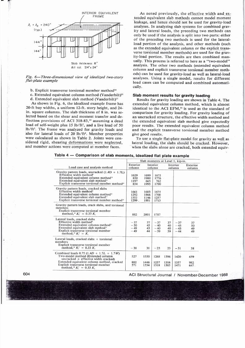
Fig.
6-Three-dimensional
view
of
ideolized two-story
flot-plate
example
b. Explicit
transverse
torsional
member
methodra
c. Extended
equivalent column method
(Vanderbilt)"
d. Extended
equivalent
slab
method
(Vanderbilt)"
As
shown
in Fig.
6, the idealized
example
frame
has
20-ftbay
widths,
a
uniform
l2-ft.
story
height, and24-
in.
square
columns. The
slab thickness
of 8
in.
was
se-
Iected
based
on the
shear and moment
transfer
and
de-
flection
provisions
of ACI
318-83,'0
assuming a
dead
load
of
self-weight
plus
15
lb/ft2,
and a live load
of 50
lb,/ft'?.
The frame was
analyzed
for
gravity
loads
and
also for
lateral loads
of 20lb/ft'z.
Member
properties
were
calculated
as
shown in Table 2.
Joints were
con-
sidered
ri
gid,
sh
e
aring
4eloflgalLb
B *y-e,f
9 t9g 99q94,
and member
actions were
computed at member
faces.
As
noted
previously,
the ef_fectjve
wid_1h and
9a
_ en{g{
equivalent
glab
m91 q{s_.
cannot model moment
leakage,
and hence
should not
be used for
gravity-load
analyses.
In
analyzing slab systems
for
combined
grav-
ity
and lateral loads,
the
preceding
two
methods can
only
be used
if
the
analysis
is
split into two
parts:
either
of the
preceding
two methods
is
used
for
the lateral-
load
portion
of the
analysis, and other
methods
(such
as
the extended_equjvalent
qolumn
or
the explicit trans-
verse
torsional
member methods)
are used
for
the grav-
ityJoad
portion.
The
results are
then combined man-
ually.
This
process
is referred
to
here
as
a
"two-model"
analysis.
The
other
two methods
(extended
equivalent
column
and explicit
transverse
torsional member meth-
ods) can
be
used
for
gravityJoad
as
well
as
lateral-load
.analyses.
Using
a
single model,
results
for
different
load
cases
can be computed
and combined automati-
cally.
Slab moment
results for
gravity
loading
Results
for
gravity
loading
are shown
in Table 4. The
extended
equivalent
column method, which
is.almost
identical
to
the
ACI
EFM,rt
is
used
as
the
standard
of
comparison
for
gravity
loading. For gravity
loading
of
an
uncracked structure,
the effective
width
method
and
the extended
equivalent
slab method give
expectedly
poor
results.
The
extended equivalent
column method
and the
explicit
transverse
torsional
member method
give good
results.
To u_sq
q
$Letj
flq :p_ el_e-q94_elfor ggavity
g ygll.as
laleral loading,
the
slabs
shquld
be
qraq[ed.
However,
when
the
slabs alone
are
cracked,
both
extended equiv-
Table
4
-
Comparison
of slab
moments,
idealized
flat
plate
example
Load
case and analysis
method
Slab
moments
at Level
1,
kip-in.
Exterior Interior
Interior
Exterior
column
column column
column
Gravity
pattern
loads, uncracked
(1.4D
+ l.7L)
Effective width
methodu
Extended
equivalent
column
method'l
Extended
equivalent slab method"
Explicit
transverse torsional mbmber
method,o
1629
850
lt97
854
r699
1980
665
1995
1675
t'176
762
1790
Cravity
pattern
loads, cracked slabs
Effective width
method"
Extended equivalent
column method"
-Extended
equivalent slab method'r
Explicit
transverse torsional member
method'o
661
292
553
299.
683
866
t46
881
6?5
700
257
7t3
Gravity
pattern
loads, crack slabs,
and torsional
members
Explicit
transverse torsional
member
method,ra
Ki
:
0.33 K,
882
2041 1787
Lateral loads,
cracked slabs
Effective width
methodu
Extended
equivalent column methodl
Extended equivalent
slab method'l
Explicit
transverse
torsional member
method,la
Ki
=
K,
-
3'1
-50
-49
-49
3'7
45
43
44
-37
_40
-40
-39
37
40
40
39
37
50
49
49
-37
-45
-43
-44
Lateral
loads, cracked slabs
+ torsional
members
Explicit
transverse
torsional member
method,'o K:
:
0.33 K,
-38
31
-23
23
-31
-16
Combined loads
0.75
(1.4D
+
l.7L
+ l.7W)
Two-model
method
(Extended
column
uncracked
+ effective
width
cracked)
Extended
equivalent column method,
cracked
Explicit
transverse
torsional member
method,'o
K,'
:
0.33 K,
52'1
882
571
I
550
t446
t534
t268
1396
123'7
1316
1318
1365
1420
6s9
t35't
982
14'71
647
604
ACI
Structural
Journal
/ November-December
1988
Page 9
8/10/2019 Comparison of Analysis Procedures for Two-way slabs
http://slidepdf.com/reader/full/comparison-of-analysis-procedures-for-two-way-slabs 9/12
alent
frame
methods
and
the
explicit
transverse
tor_
sional
member
method give
erroneous
results
fo1
grav;
ity-load
cas-es.
As
shown
in
Table
4,
decreasinl
the
slab-beamstif
f
nes5_i4qgagqstherl"b-";;*;;;:
p
o it
s,
lelh
er
t.
hAqtqigAfqll
eA
_4,rt,
;r
a
u
e
ex
_
p6ctEd-ihe-rea;n-iilahE
is
ifiaTiri"
.;iffi*
"*
onliiictrid
to
the
torsional
members
rather
than
to
the
slab-beams.
When
the
latter
are
made
more
flexible,
the
increased
relative
stiffness
of the
torsiorrt-;;;;;;$ii
causes
support moments
to
increase.il,ra
The
solution
to
this
problem
is
to include
the
effects
of
cracking
in
the
transverse
torsional
members
as
well
as
the
slabs.
This
modification
is
easy
to
carry
out with
the
explicit
transverse
torsional
*.-L.,
method.
Table
4
shows
the results
for
Ki
:
0.33
K,.
-Bggu-lts
are
close
to
those
of
the extended
equivalent
cotrrr--metnoO
Cuncraakeil
case)
:'
'
-
Slab
moment
results
for
laterat
loading
Lateral
loading
results
are also
shown
in
Table
4.
When
slabs
alone
are
cracked,
all four
meth.ods give
similar
results.
When
transverse
torsional
members
are
also
crackedln
the
case
of
the explicit
transverse
tor_
sional
member
method,
moments
are
decreased
slightly.
Slab
moment
resutts
for
combined
loading
(gravity
plus
laterat)
Combined
loading
results
are also
shown
in
Table
4.
Using
the
"two-model',
procedure,
gravity_load
mo_
ments
calculated
using
the
extended
equivalent
column
method (uncracked
members)
are
combined
with
lat_
eral-load
moments
calculated
using
the
extended
equiv8
alen _
qla _me1ho,{
(crackbd
slabs).
Using
tfre
t,single_
model"'procedure,
gravity-
and iateral_ltad
moments
are
calculated
using
the
extended
equivalent
column
method,
as
well
as
the
explicit
transverse
torsional
member
method.
Cracking
is
taken
into
account
for
the
slab-beams
in
each
case.(Ii
=
0.33 1r).
Because
the
ex_
tended
equivalent
column
rirettrOa
does
not permit
easy
incorporation
of
cracking
of
the torsional
members,
ii
gives
erroneous
results
for
the combined
load
case.
The
explicit
transverse
torsional
riremlier
method,
on
the
.
other
hand, gives
results
close
to
those
of
the
two_
model
method.
COMPARISON
OF
DIFFERENT
ANALYSIS
METHODS:
tDEAL|ZED
TWO.WAY
SLAB
ON
BEAMS
To
compare
the
accuracy
and
convenience
of
differ_
ent
slab
analysis
methods,
the
four
methods
were
used
to
compute
slab-beam
moments
in
an idealized
two_
story
frame
made
up
of
two-way
slabs
on
beams:
a. Effective
width
method
(ACI
effective
width for
T-beams).Io
b.
Explicit
transverse
torsional
member
method.ra
-
.-c.
Extended
equivalent
column
method (Vander_
bilt).'r
d.
Extended
equivalent
slab
method (Vanderbilt).il
-
As
shown
in
Fig.
7,
the
idealized
frame
has
two_way
.sl1b1
on
beams,
20-ft
spans,
a uniform
l2_ft
story
height,
and
l6-in. sqrar.
columns.
The
slab
thickness
ACI
Structural
Journal
/
November_December
lggg
Fig.
7-Plan
view
of
idealized
two-story,
two_woy
slab
with
beams
example
of
6
in. was
selected
based
on
the deflection
provisions
of ACI
318-83,'0
assuming
a
dead
load
of
self_weight
plus
15
lb/ft2,
and
a live
load
of
SO
lb/ftr.
The
frame
was
analyzed
for
gravity
loads,
afid
also
for
lateral
Ioads
of 20
lb/ftr.
Joints
were
considered
rigid,
shear_
ing
deformations
were
neglected,
and
member
actions
were
computed at member
faces.
The
frames
were
analyzed
using
both
two_model
and
single-model
procedures.
For
the
effective
width
method,
widths
of
slab-beam
members
weiil
as
ildfined
bt
tfie
T-beam
width provisions
of
ACI
3t8-g3
(Refer_
ence 10).
Effects
of
slab-beam
cracking
were
accounted
for
using
an
average
effective
moment
of
inertia,
equal
in
this
case
to
abofi
0.42
times
the
gross
inertia.,.
For
the
qlh.qr-fngtg4s,
slab-beams
and
transverse
torsional
members
were
as
defined
by
the
ACI
equivalent
frame
method.10
Effects
of
slab-beam
cracking
were
ac_
counted
for
using
an
average
effective
moment
of in_
ertia,
equal
in
this
case
to
about
0.70 times
the
gross
inertia.ta
Column
stiffnesses
were
calculated
using
the
gross
inertia,
multiplied
by
a reduction
factor
equal
to
0.75
(Reference
l0).
procedures
for
calculating
mem_
ber properties
are
summarized,
in
Table
3.
Slab.beam
momenl
results
for
gravity
loading
These
results
are shown
in
Table
5.
The
extended
equivalent
column
method (uncracked
case),
almost
identical
to
the
ACI
EFM,I
is
used
as
the
standard
for
comparison
for
gravity
loading.
For gravity
loading
of
the uncracked
structure,
the
extended
equivalent
slab
method
gives expectedly
poor
results,
,hil"
th.
,*_
tended
equivalent
column
method
and
the
explicit
transverse
torsional
member
method give
almost
iden_
tical
results.
When
the
slab-beams
alone
were
cracked,
the
ACI
effective
width
method
and the
extended
equivalent
slab
method
were
much
less
accurate
than
the
other
methods.
Both
the,extended
equivalent
column
method
and
the
explicit
transverse
torsional
member
method
gave
slightly
high
results,
although
not
as far
off
as
those
of
the
preceding
flat-plate
example.
As
before,
this
problem
was resolved
by
using
thi
explicit
trans_
verse
torsional
member
method
with
cracked
torsional
members as
well
as
slab-beams.
Results
are very
close
605
4
IO x
2O
spondrels
l2
x 2O girders
lnterior
equivolent
frome
'
Slory height
=
l2'
Slob
lhickness
=
6"
All columns,
16"x
16"
l.2ao"
+
2+o"
l.
2ao"
+
Page 10
8/10/2019 Comparison of Analysis Procedures for Two-way slabs
http://slidepdf.com/reader/full/comparison-of-analysis-procedures-for-two-way-slabs 10/12
I1l9J-_-comparison
ol
srab-bearn
moments,
ideatized
two.way
srab
on
Deams
example
to
those
given
by the
extended
equivalent
column
method (uncracked
case).
Slab-beam
moment
results
for
laterat loading
These
are also given
in
Table 5.
All
methods
ixcept
the
ACI
effective
width
method
give
satisfactory
re-
sults.
Unlike
the
preceding
flat-plate
example,
torsional
member cracking using the
explicit
transverse
torsional
member
method
does
not significantly
decrease
slab-
beam
moments
under lateral
load.
Slab.beam
moment
results for
combined loading
(gravity
plus
lateral)
These
results
are also
shown
in Table
5.
Using
the
"two-model"
procedure, gravity-load
moments
calcu-
lated using
the
extended
equivalent column
method (no
cracking)
are combined
with
lateral-load
moments
cal-
c u
I
at
ed u
s
i n
g
t h e ex.t
e
n
{
e-{
e
qqi_vp _e_n
-
Clab
_ir1g Lq*4'j
(cracked
slab-beams
and coiumns).
Using
tha
;;sin;i;-
model"
procedure,
gravity-
and lateral-load
moments
are calculated using
the
extended
equivalent column
method,
as
well
as the
explicit
transverse
torsional
member
method.
Slab-beam
and column cracking
are
considered
identicalty
in
both
cases,
and torsional
member
cracking
is considered
in
the
Iatter method.
As
shown
in Table
5, all
three methods give
acceptable re-
sults. The
single-model
procedures
are
much more
con-
venient.
SUMMARY
This
report
has focused
on the
following
analysis
methods
for
two-way
reinforced
concrete
slabs:
606
1.. Effective
width
methods,
exemplified
by
the
method
of Khan
and Sbarounis.6
2.
Transverse
torsional
member methods.
a.
ACI
equivalent frame
method.to
b.
Extended
equivalent
slab
method
(Vanderbiltlr).
c.
Extended
equivalent
column
method
(Vanderbiltrr).
d. Explicit
transverse
torsional
member
metfod.ra
The
ACI
equivalent
frame method
was
developed
and
calibrated
for
single-story
substructures
under
gravity
loads
and
cannot be
consistently
applied to
multistory
structures.,
In the
extended
equivalent col-
umn
and
extended
equivalent
slab niethods,
the
tor-
sional
stiffnesses
K,
of
the
transverse
torsional
mem-
bers
are
distributed
between
adjoining
columns
or slab-
beams,
respectively.
Both
methods
are used
with
a
spe-
cialized
computer
program.rT
The
explicit
transverse
torsional
member
method
accounts
directly
for
mo-
ment
leakage
and
slab
torsional
flexibility.
It
requires
only
conventional computer programs and can
be
spe-
cialized
to either
of
the extended methods.
Lateral
deflections
computed
by all
methods
were
checked
against results
obtained
from
an
uncracked,
scale-model,
flat-plate
structure.re,20
While
results
from
the effective
width
method
were
most
accurate, the
slightly
greater
drifts
predicted
by the
other
methods
might
be
more reasonable
in
a real
structure
with
some
cracking.
All
methods were considered
to
give
satisfac-
tory
deflection
calculations.
The
preceding
methods were
also compared
with
re-
spect
to
accuracy
and
convenience in
calculating
mo-
ACI
Structural
Journal
/
November-December
19gB
Load
case
and
analysis
method
Slab-beam
moments
at
Level
l, kip-in.
Exterior
Int.rioffi
column
column
column
column
Gravity
pattern
loads, uncracked
(1.4D
+
lr7L\
ACI
effective
T-beam
width
meihod,o.r4
'
Extended
equivalent column
methodri
Extended
equivalent
slab method',
Explicit
transverse
torsional
member
method,n
1457
196'7
948
20s7
1083 1584
952
20',12
814
881
513
895
Gravity
pattern
loads, cracked
slabs
ACI
effective T-beam
width
method,o',.
Extended equivalent column method,,
Extended
equivalent
slab method,,
Explicit
transverse
torsional member
method14
1591
99s
1 103
1002
1908
2065
t'709
2080
805
8'74
605
889
Gravity
pattern
loads, cracked
slabs
+ torsional
members
Explicit
transverse
torsional
member
method,'o
K,'
=
0.70 K,
962 2089
r
896
Lateral
loads,
cracked slab-beams
+
columns
ACI
effective
T-beam
width
methodr0.,a
Extended equivalent
column
method,,
Extended
equivalent
slab method',
Explicit
transverse
torsional
member
method,'a
Ki
:
K,
-
105
100
-164
133
-
163
129
-164
133
-95
95
-
l0l
l0l
-
104
104
-
10t
101
-
100
-
133
-
129
-
133
105
t64
163
164
Lateral
loads, cracked
slabs
+ columns
+
torsional
members
Explicit
transverse
torsional
member
method,'a Ki
=
0.7O K,
163
131
-99
99
163
31
Combined
loads 0.75
(1.4D
+
t.7L
+
l.7Wl
Two-model
method
(extended
column
unoacked
+
effective
width
cracked)
Extended
equivalent column
method,'ciacked
Explicit
transverse
torsional
member
method,'o
K,'
:
0,70
K,
606
583
559
1643
r683
t700
l3r6
1506
130'7
1509
1324
1523
1443
817
t418
9lt
1437
885
Page 11
8/10/2019 Comparison of Analysis Procedures for Two-way slabs
http://slidepdf.com/reader/full/comparison-of-analysis-procedures-for-two-way-slabs 11/12
Page 12
8/10/2019 Comparison of Analysis Procedures for Two-way slabs
http://slidepdf.com/reader/full/comparison-of-analysis-procedures-for-two-way-slabs 12/12
l
ii
ir
ii
ri
ii
REFERENCES
l. Design
of
Reinforced
Concrete
Slabs '
questionnaire
distrib-
uted
by
ACI-ASCE
Committee
421'
1986'
i.iuri,
Robert,
and Gamble,
William
L
Reinforced
Concrete
Slabs,
John
Wiley
&
Sons,
New
York,
1980'
pp'
274-464'
3. Hillerborg,
Arne,
S/rrp
Method
of
Design'
Cement
and
Con-
crete
Association,
Wexham
Springs,
191 5'
256
pp'
4.
Pecknold,
David
A., Slab
Effective
Width
for Equivalent
Frame
Analysis,
ACI
JouRNAL,
Proceedings
V' 72'
No'
4 Apr'
1sls,
pp.
tl\-tsl
.
Also,
Discussion
bv
F' H'
Allen'
P'
leP' Darvall'
n.
g.
Ctover,
and
D.
A. Pecknold,
Proceedings
V'
72, No'
10'
Oct'
1975,
pp.
583-586.
S.
Btias,
ZiadM., Lateral
Stiffness
of
Flat
Plate
Structures '
ACI
JounNer,
Proceedings
V.
80,
No.
1,
Jan'-Feb'
1983,
pp'
50-54'
6. Khan,
Fazlur
R',
and
Sbarounis,
John
A', Interaction
of
Shear
Walls and
Frames,
Proceedings,
ASCE,
V'
90'
ST3'
Part
l,
June
1964,
pp.
285- 335.
7.
Corley,
W.
Gene; Sozen,
Mete
A.;
and
Siess,
Chester
P', The
Equivaleni
Frame
Analysis
for
Reinforced
Concrete
Slabs,
S/ruc-
tural
Research
Serres
No.
218, Department
of
Civil
Engineering,
University
of
Illinois,
Urbana,
June
1961,
168
pp'
8. Jirsa,
James
O.;
Sozen,
Mete
A.;
and
Siess,
Chester
P', Pattern
Loadings on
Reinforced
Concrete
Floor
Slabs,
Proceedings,
ASCE,
V.95,
3T6,
June
1969,
PP.
l1l7-1137'
9.
Corley,
W.
Gene,
and Jirsa,
James
O., Equivalent
Frame
:
Length
of span
transverse
to
direction
of
the span
for
which moments
are being determined,
measured
center-to-
center of
supports
(ChaPter
13)
:
Effective width factor
=
Uniform
rotation
at column,
used
in
deriving
effective
width factor o
CONVERSION
FACTORS
I
ft
=
0.305
m
I in.
=
25.4
mm
I lb/ft2
=
4.882k9/m'
I kiP
:
4'448
kN
I ksi
=
6.895
MPa
I
Psi =
0.006895
MPa
Analysis
for
Slab
Desigp.
ACI
Jcnxrr'
hoceedings
Y
'
67'
No'
1 I
'
Nov.
1970,
pp.
875-8&l-
AIso,
Discussion
by
A'
C'
Eberhardt'
E'
S'
Hoffman,
Ti Huang,
J.
C.
Jofrirr'
Y' K'
Hanson'
and
Closure'
Pro-
ceedings
V.
68,
No.
5,
May
l97l'
pp'
397-4OI'
10'ACICommittee3lE'..B'JilditrgCodeRequirementsforRein.
forced
Concrete
(ACI
318-83) '
American
Concretelnstitute'
De-
troit,
1983,
111
pp, and Commeatary
on
Building
Code
Require-
ments
for
Reinforced
Concrete
(ACI
318{3)
155
pp'
11.
Vanderbilt,
M.
D., Equivaleot
Frame
Analysis
of
Unbraced
Reinforced
concrete
Buildingi
for
Static
Lateral
Loads,
structural
Research
Reporl
No. 36,
Ci;il
Engineering
Departmenr'
Colorado
State
University, Fort Collins, Colorado, July
1981'
,
-
iZ.
Vuna.rUitt,
M.
Daniel, pquivalent
Frame
Aoalysis
for
Lateral
Loads,
Proceedings,
ASCE,
V. 105,
ST10,
Oct'
1979'
pp' 1981-
1998.
Also,
Discussion
by ZiadM.
Elias,
V.
106,
ST7,
July
1980'
pp'
167l-1672,
and Closure,
V.
107, STl,
Jan.
1981,
p'
245'
13.
Vanderbilt,
M.
Daniel,
and
Corley,
W.
Gene, Frame
Analysis
of
Concrete
Buildings,
Concrete
Internotionol:
Design
& Construc-
tion,Y.5,
No.
12, Dec.
1983,
pp.33-43.
14.
Cano,
M.
T., Comparison
of
Analysis
Procedures
for
Two-
Way Slabs,
MS
Thesis,
Depaftment
of
Civil
Engineering,
Univer-
sity
of
Texas,
Austin,
Aug.
1984.
l5. Reinforced
Concrete
Floor
Slabs
-
Research
and
Design,
Bulletin
No.
20, Reinforced
Concrete
Research
Council,
American
Society
of Civil
Engineers,
New
York,
1918,209
pp.
16. Guralnick,
Sidney
A., and
LaFraugh,
Robert
W., Laboratory
Study
of
a
45-foot
Square
Flat
Plate Structure,
ACI
JounNel,
Pro-
ceedings
V.60, No.9,
Sept'
1963,
pp.
1107-1185.
17.
EFRAME,
computer
program' National
Information
Service
in
Earthquake
Engineering,
University
of
California,
Berkeley'
18.
Wilson,
E.
L.,
Hollings,
J. P.
and
Dovey,
H'
H', Erars:
Three-Dimensional
Analysis
of
Building
Systems
(Extended Ver-
sion),
computer
program' National
Information
Service
in
Earth-
quake Engineering,
BerkeleY,
1977.
19.
Zelman,
Maier
I.;
Heidebrecht,
Arthur
C.;
Tso,
W'
K'; and
Johnston,
William A', Practical
Problems
and Costs
of
Fabricating
Multi-story
Models,
Models
for
Concrete Struclures,
SP-24,
Amer-
ican Concrete
Institute,
Detroit,
1970'
pp.
159-185'
20.
Hartley, G.;
Rainer,
J. H;
and Ward,
H.
S', Static
and Dy-
namic Properties
of
a Reinforced
Concrete
Building
Model,
Build-
ing
Research
No.
140,
Division
of
Building
Research,
National
Re-
search
Council
of
Canada,
Ottawa'
Apr. 1919,24pp'
608
ACI
Structural
Journal
/
November-December
19BB