TABLE OF CONTENTSTITLE PageSAFETY PRECAUTIONS ......................................................3INTRODUCTION General ..................................................................................4Suction Lift............................................................................4Scope ....................................................................................4SETUPUnpacking ............................................................................5Assembly ..............................................................................5Tubing Selection ..................................................................5INSTALLATIONSite Requirements................................................................5Power Requirements ..........................................................5DESCRIPTIONFunctional Description ........................................................6Controls, Indicators and Connectors ................................6Wetted Parts ........................................................................6Familiarization with System Features ................................7INITIAL OPERATIONSystem Boot-Internal Battery ............................................8System Boot-External Power..............................................9Battery Charging ................................................................10Setting Time and Date ......................................................10Security ..............................................................................10Locking the Keypad ..........................................................11OPERATIONDescription of Programming ............................................11Starting/Stopping a Program ............................................11Cancelling a Program ........................................................11Accessing the Menu ..........................................................11Menu....................................................................................12Navigation ..........................................................................14GLOBAL SETTINGSGeneral ................................................................................14Global Settings Tour ..........................................................14VIEW/EDIT PROGRAMSGeneral ................................................................................19Program Menu Tour ..........................................................19SAMPLING PROGRAM MENU OPTIONSGeneral ................................................................................22Program Start ....................................................................22Sample Volume ..................................................................23# of Contact Closures ........................................................24Default Program Settings ..................................................25Save Program ....................................................................25Hot Keys..............................................................................26
CALIBRATING THE SYSTEMGeneral ................................................................................26Minimum Sample Size ......................................................26Required Equipment ..........................................................26Calibration Procedure........................................................26Previous Calibrations ........................................................27CYCLING THE SYSTEM ....................................................27MAINTENANCECleaning ..............................................................................27Sample Reservoir Vents ....................................................27Tubing..................................................................................27TROUBLESHOOTINGGeneral ................................................................................28Error Status/Messages and Solutions ............................28USER REPLACEMENT PARTS/SERVICINGInternal Battery Replacement ..........................................29USER REPLACEMENT PARTS ..........................................30ACCESSORIES ..................................................................30SPECIFICATIONS ..............................................................31WARRANTY ........................................................................32PRODUCT RETURN ..........................................................32TECHNICAL ASSISTANCE ................................................32ACCESSORY OPERATING INSTRUCTIONS07571-50 Automotive Power Adapter ..............................3307571-52 & -54 Auxiliary Power-Pak ................................3407580-60 Remote Contact Closure Adapter Cable ........3707580-65 RS-232 Adapter..................................................37
Trademarks bearing the ® symbol in this publication are registered in the U.S. and in other countries
® ®
3
SAFETY PRECAUTIONS
DANGERS: NEVER apply AC voltages directly to the EXTERNAL POWER INPUT receptacle on the frontpanel. The application of AC voltages can result in injury and death of the operator and destruction of the unit. Use only the AC/DC Universal Power Supply/Converter supplied with the unit to power unit from an AC source.
NEVER short or connect the terminals of the battery terminals together. Shorting of the battery terminals causes rapid internal heating of the battery resulting in the explosion of the battery and severe injury to or the death of the operator.
DO NOT BURN OR INCINERATE THE BATTERY. THE BATTERY MAY EXPLODE CAUSING SEVERE INJURY OR DEATH OF THE PERSONNEL IN THE AREA. (Dispose of the old battery by recycling.)
DANGER: The AC/DC Universal Power Supply/Converter is rated for INDOOR USE ONLY. DO NOT use the AC/DC Power Supply/Converter in an outdoor environment to either charge the battery or power the drive. Electrical shock, severe injury and/or death are possible if this warning is ignored.
CAUTIONS: Do not reverse the connections to the battery. If the battery connections are reversed, damage to the unit will occur.
Fully charge the unit before using for the first time. Damage to the internal battery can result if the battery is in a fully discharged state and operation of the unit is attempted.
Immersion or submersion of the unit will result in improper operation and possible damage to the unit.
Use of pump heads, tubing sizes and formulations other than those specified in this manual, or the mounting and use of two or more pump heads concurrently will result in improper operation and possible damage to the unit.
If the battery connections are reversed, damage to the unit may occur. The battery terminalsare color coded. Connect the black wire to the black terminal, and the red wire to the red ter-minal.
WARNINGS: Tubing breakage may result in fluid being sprayed from the pump. Use appropriate measures to protect the operator and equipment.
Turn drive off, remove all the power to the unit, including the AC/DC Power Supply/Converter, Automotive Power Adapter or other external power source if present before removing or installing pump head or tubing. This will help prevent accidental activation of the drive mechanism so fingers or loose clothing will not get caught in the pump drive mechanism.
PRODUCT USE LIMITATION This product is not designed for, nor intended for use in, patient-connected applications, including, but not limited to, medical and dental use and, accordingly, has not been submitted for FDA approval.
WARNING: PRODUCT USE LIMITATION
This product is not designed for, nor intended for use in, patient-connected applications, including, but notlimited to, medical and dental use and, accordingly, has not been submitted for FDA approval.
® ®
4
INTRODUCTION AND GENERAL DESCRIPTION
EXTERIORHOUSING
LEVEL SENSOR
KEYPAD
ON/OFF 0-1STATUSSWITCH
EXTERNALPOWER INRECEPTACLE
RS-232 CONNECTOR
SAMPLERESERVOIR
FLOWDETECTOR
MASTERFLEX EASY-LOAD PERISTALTIC PUMP
CONTROLCONSOLE
FIGURE 1
GENERAL The MASTERFLEX® E/S® Composite Sampler is a DSP controlled, portable, self-contained, programmable peristalticpump system designed to meet EPA, NPDES guidelines forthe sampling of storm and waste water.
The MASTERFLEX E/S Composite Sampler as shown inFigure 1, consists of an exterior housing, a controls consolewhich contains the internal power source, pump drive systemand system controls, a MASTERFLEX® L/S® EASY-LOAD®
peristaltic Pump Head and a sealed and vented sample reservoir. The drive system is capable of operating one MASTERFLEX® L/S® Standard®, L/S® EASY-LOAD® or L/S®
PTFE Pump Head.
The MASTERFLEX E/S Composite Sampler is current limited,protected from reverse power supply polarity and transientvoltages.
You may operate the MASTERFLEX E/S Composite Sampleron the internal battery, an external 12V DC source or indoorsusing the 115V AC or 230V AC with the AC/DC UniversalPower Supply/Converter supplied with the unit.
The system features a built-in spill-proof gel battery andrecharging system allowing the unit to be recharged from anAC power source using the supplied AC/DC Universal PowerSupply/Converter or from an automotive 12V DC electricalsystem if used with the Automotive Power Adapter accessory.
It is designed and programmed to accept, control and powerone MASTERFLEX L/S EASY-LOAD, Standard or PTFETubing Pump Head for fluid transfer and sampling in the field.
The unit is housed in a high visibility, protective polyethylenehousing. The control panel and the drive controls have anenvironmental protection rating of IP56.
When closed and latched, the drive will float for a minimum of30 minutes if dropped into a lake or stream to allow recoveryof the unit.
SUCTION LIFTThe MASTERFLEX E/SComposite Sampler is capable of lifting a sample of water up to twenty-five (25) feet vertically.This capability is called suction lift and is measured from the surface of the liquid to the Pump Head.
If the liquid to be sampled has a viscosity or density greaterthan water, this lifting capability is reduced or diminished.This lifting capability is also diminished as altitude above sea level increases.
SCOPE OF THE MANUALThis manual contains instructions for installing, setting up,programming, operating and maintaining the sampling system. It is intended for use by technicians and operators as well as maintenance personnel. The TROUBLESHOOTINGsection contains a list of possible problems, their probablecauses, and actions to take to remedy each problem.
Instructions for replacing user-serviceable parts and a list ofparts that can be ordered are included.
The ACCESSORIES section lists all available accessories forthe MASTERFLEX E/S Composite Sampler.
® ®
5
SETUPUNPACKINGCare has been taken in the packaging of the MASTERFLEXE/S Composite Sampler to protect it in transit to its final desti-nation. After opening the carton, save the packing material untilproper product operation has been verified.
The MASTERFLEX E/S Composite Sampler consists of the following items:
ASSEMBLINGUnit is shipped fully assembled and plumbed with MASTERFLEX L/S 24 size silicone peroxide-cured tubing. Theoperator only needs to connect an external sample line usingthe supplied tubing connector into Sample Line Inlet bulkhead connector shown in Figure 2.
TUBING SELECTIONThe flow rate at which a sample can be taken is dependenton the tubing size, tubing material and the height the samplemust be raised to enter the sample reservoir. The purity ofthe sample is dependent on the formulation of the tubingmaterial. The Composite Sampler is supplied with L/S® 24size tubing made of peroxide-cured silicone resins. The tubing supplied with the unit has been selected based on its purity versus flow and lift performance. Optimum lift andflow performance can be had by using TYGON® LFL® or Labtubing.
See Table 1 for other tubing materials and sizes available foroperation with the Composite Sampler.
INSTALLATION
SITE REQUIREMENTSThe E/S Composite Sampler is designed to operate in mostoutdoor conditions. Ensure that the work area temperaturerange is between 1°C to 50°C (34°F to 122°F) and that the relative humidity remains between 10% and 90%.
Position the sampler in an upright position with the carryinghandle at the top of the case (as shown), preferably on a firmlevel surface, adjacent to the source to be sampled. The sampler may also be suspended or attached to a vertical support using the D-rings at the top of the exterior housing.
POWER REQUIREMENTSThe MASTERFLEX Composite Sampler is internally powered bya 12V sealed gel battery. The unit may also be operated orcharged in an outdoor environment using the AutomotivePower Adapter Accessory 07571-50, Auxiliary Power Pack07571-52 or 07571-54, or any DC source supplying 11-18 volts.
Sampler can be operated or charged indoors from a 115 (90-130) V AC or 230 (180-260) V AC 50/60 Hz incoming powerusing the AC/DC Universal Power Supply/Converter (supplied).
DANGER: NEVER apply AC voltages directly to the EXTERNAL POWER INPUTreceptacle on the front panel. Theapplication of AC voltages can resultin injury and death of the operatorand destruction of the unit. Use only the AC/DC Universal Power Supply/Converter supplied with the unit topower unit from an indoor ACsource.
CAUTION Fully charge the unit before using forthe first time. Damage to the internalbattery can result if the battery isfully discharged and operation of theunit is attempted.
Tubing formulation L/S® 15 L/S® 24
Silicone, peroxide-cured 96400-15 96400-4
TYGON, Lab® 06409-15 06409-24
TYGON LFL® 06429-15 06429-24
PHARMED® BPT 06485-15 06485-24
TABLE 1 Tubing Materials
® ®
6
DESCRIPTIONFUNCTIONAL DESCRIPTIONThe control console of the Composite Sampler provides theoperator interface for programming, control and charging of thesampling system. The DSP in the control console scans thekeypad, communicates to the display, communicates with theintegral pump drive, assesses the state of and controls charging of the battery.
The system is preprogrammed with one (1) fluid transfer program and five (5) sampling programs. All of the factory-supplied sampling programs can be modified by the operatorand saved without modifying or destroying the factory supplied programming. The factory supplied programmingand operational parameters are stored in non-volatile flashmemory within the DSP controller.
Program options and instructions from the operator arestored in non-volatile memory consisting of an EEPROMwhich supplements the flash memory of the DSP.
CONTROLS, INDICATORS ANDCONNECTORSAll the controls, connectors, and indicators on the controlsconsole and exterior housing are shown in Figure 2 and 3.Table 2 lists all of the operator controls and indicators.
WETTED PARTSAll parts in direct contact with the sample being taken areconsidered wetted parts. The following is a listing of the wetted parts and their associated materials.
Sample intake tubing: Unit is supplied with ¼″ ID 25 feet ofMASTERFLEX L/S® 24 size peroxide-cured silicone tubing.
Sample reservoir: HDPE (high density polyethylene)
Sample reservoir cap: polypropylene
Breather vents, sample reservoir: medical gradeABS/TEFLON®
BULKHEAD CONNECTOR,
SAMPLELINE INLET
REMOTE CONTACTCLOSURE
CONNECTOR
RS-232CONNECTOR
EXTERNAL POWER INRECEPTACLE
11-18V DC
ON/OFF 0-1 STATUS
SWITCH
FIGURE 2
Pam Nazar
Note
are you still using teflon here?
® ®
7
Control or indicator Description and function
0-1/ STATUS Use to turn the unit ON, OFF, check unit status or awaken unit from an inactive mode.
DISPLAY 24 character by two-line LCD that displays all menus needed for programming and operating the system.
MENU Use to access the menu.
Selection arrow keys Use to navigate menu options shown on the display.
Numeric keypad 0-9 Use for numeric entry.
START/STOP Use to initiate program or to stop a program which is running.
CANCEL Cancels any changes that were made to the current menu selection and returns to previous menu.
ENTER Accepts the selected item and moves down to the next menu level. If there is not a lower menu level, it will return to the top level for the selected item.
CLOCK Used to set date and time. The date is displayed in a MM:DD:YY format. The time format is a 24-hour clock displayed in a HH:MM:SS.
TIME Used to access the time settings in the loaded program.
SAMP. VOL Used to access the sample volume parameter in the loaded program without going through the menu.
LIFT HEIGHT Used to access the lift height parameter in the loaded program without going through the menu.
CYCLE TEST Used to verify unit operation in the field.
CAL Used to verify and calibrate unit in the field for accurate sample delivery.
TABLE 2 Operator Controls and Indicators
FIGURE 3
FAMILIARIZATION WITH SYSTEM FEATURESThe system has unique features with which the operator needs tobecome familiar during the course of system operation. Understandingthe features will enable the operator to know if the system is operating properly and effectively. These features are as follows:
1. Automatic Power-Up: Any time an external power source isconnected to the EXT POWER IN receptacle located on the front of the control console, the system will power up and go through aboot up routine or display a system message as to system status. If no action is taken, the system will charge the battery.
2. Automatic Power Conservation: If the system is not imple-menting an internal command or the operator has not pressed akey on the control console for 10 minutes the system, to conservepower, will POWER DOWN. The LCD display will display a mes-sage for 5 seconds:
POWERING DOWN
8
®®
After which the display will blank. If an external power sourceis connected at the time, the battery will continue to chargewhile the display is blank. If a sampling program was runningor in process at the time of power down the system will continue to run the program. The display panel will show amessage when the unit starts to take a sample and show the time until the next sample is to be taken. The display willremain active for an additional 5-10 seconds before returningto a powered down state.
If the display panel is not active, press the 0-1/STATUS keyon the control console to awaken the system.
3. Automatic Battery Charging: System will automaticallycharge the internal battery any time an external power sourcesuch as the AC/DC Universal Power Supply/Converter orAutomotive Power Adapter is plugged into the EXT PWR INreceptacle. The rate at which the internal battery is chargedwill vary with other system operations. Once the battery isfully charged, the integral battery charging circuit will placethe battery on a floating or maintenance charge to maintainthe battery in a fully charged state.
4. Automatic Purging: The system will automatically purgethe sample intake line prior to the taking of any sample or theoccurrence of a rinse cycle. This is to ensure that the sampleinlet line is free of any obstructions or debris.
5. Glow-In-Dark Keypad: The keypad is printed with phosphorescent pigments. These pigments will glow for up to 20 minutes if exposed to ultraviolet radiation from the sunor a krypton flashlight. This feature is helpful in low ambientlight conditions. The LCD display is backlightable and whenused with keys that glow in the dark, this lessens the need forexternal lighting in dim and dark areas.
INITIAL OPERATIONSYSTEM BOOT—INTERNAL BATTERYPress the 0-1/STATUS button on the control console. TheLCD display will activate and display the following messages:
System will power up the drive system to place the internalbattery under load and verify its condition.
The LCD panel will display one of the following messages,depending upon battery condition.
If the battery is fully charged or you pressed cancel whennotified the battery is low, the system will complete boot-upand display the following on the LCD screen:
If the message displayed is:
The system should not be operated until the battery has beencharged or an external power source has been connected tothe unit. Proceed to the BATTERY CHARGING section of themanual on page 10.
SAMPLER ON VERSION X.X
CHECKING BATTERYPRESS CANCEL TO QUIT
BATTERY FULLY CHARGED
BATTERY IS LOWCHARGING IS RECOMMENDED
SAMPLER SYSTEM READYHH:MM:SS MM/DD/YYYY
BATTERY IS VERY LOWMUST CHARGE BATTERY!
®
SYSTEM BOOT— EXTERNAL POWEROpen the exterior housing, connect the AC/DC UniversalPower Supply/Converter into the EXT PWR IN receptacle onthe front. Then connect the AC plug into an AC receptacle.The system will come on automatically. The first screen dis-played on the LCD panel will be:
This will be followed by another screen:
Remove the plug from the EXT PWR IN receptacle on thecontrol console. LCD will change to read:
The system will power up the drive system to place the internal battery under load and verify its condition. After thedrive system has stopped, you may reconnect the externalpower to the EXT PWR IN receptacle. The LCD panel will display one of the following messages, depending upon battery condition.
If the battery is fully charged or you pressed cancel whennotified the battery is low, the system will complete boot upand display the following on the LCD screen:
If the message displayed is:
The system should not be operated until the battery has beencharged. Proceed to the BATTERY CHARGING section of themanual on page 10.
SAMPLER ON VERSION X.X
REMOVE EXT PWR TO CHECKBATTERY—CANCEL TO SKIP
CHECKING BATTERY PRESS CANCEL TO QUIT
BATTERY IS FULLY CHARGED
BATTERY IS LOWCHARGING IS RECOMMENDED
BATTERY IS VERY LOWMUST CHARGE BATTERY!
SAMPLER SYSTEM READYHH:MM:SS MM/DD/YYYY
9
®
10
®®
SAMPLER SYSTEM READYHH:MM:SS MM/DD/YYYY
BATTERY CHARGINGThe Composite Sampler is equipped with an internal fourstate battery charger capable of diagnosing and automaticallycharging the internal battery. The operator only needs to connect the AC/DC Universal Power Supply/Converter orAutomotive Power Adapter accessory. The sampler systemwill automatically power up and begin charging the battery.After 10 minutes the LCD display on the control console willpower down, going blank. The battery will continue to chargeuntil it has reached is full potential. Once the battery is fullycharged, the battery will be placed on a float or maintenancecharge until the external power source is disconnected.
The system may run or be programmed while the unit ischarging. Battery charging will continue in the backgroundwhile other operations are taking place. Allow a minimum of8 hours to fully charge the battery from a fully dischargedstate with no other operations occurring. During batterycharging all functions of the sampler are operational.
DANGER! The AC/DC Universal Power Supply/Converter is rated for INDOOR USEONLY. DO NOT use the AC/DC PowerSupply/Converter in an outdoor environment to either charge the battery or power the drive. Electricalshock, severe injury and/or death arepossible if this warning is ignored.
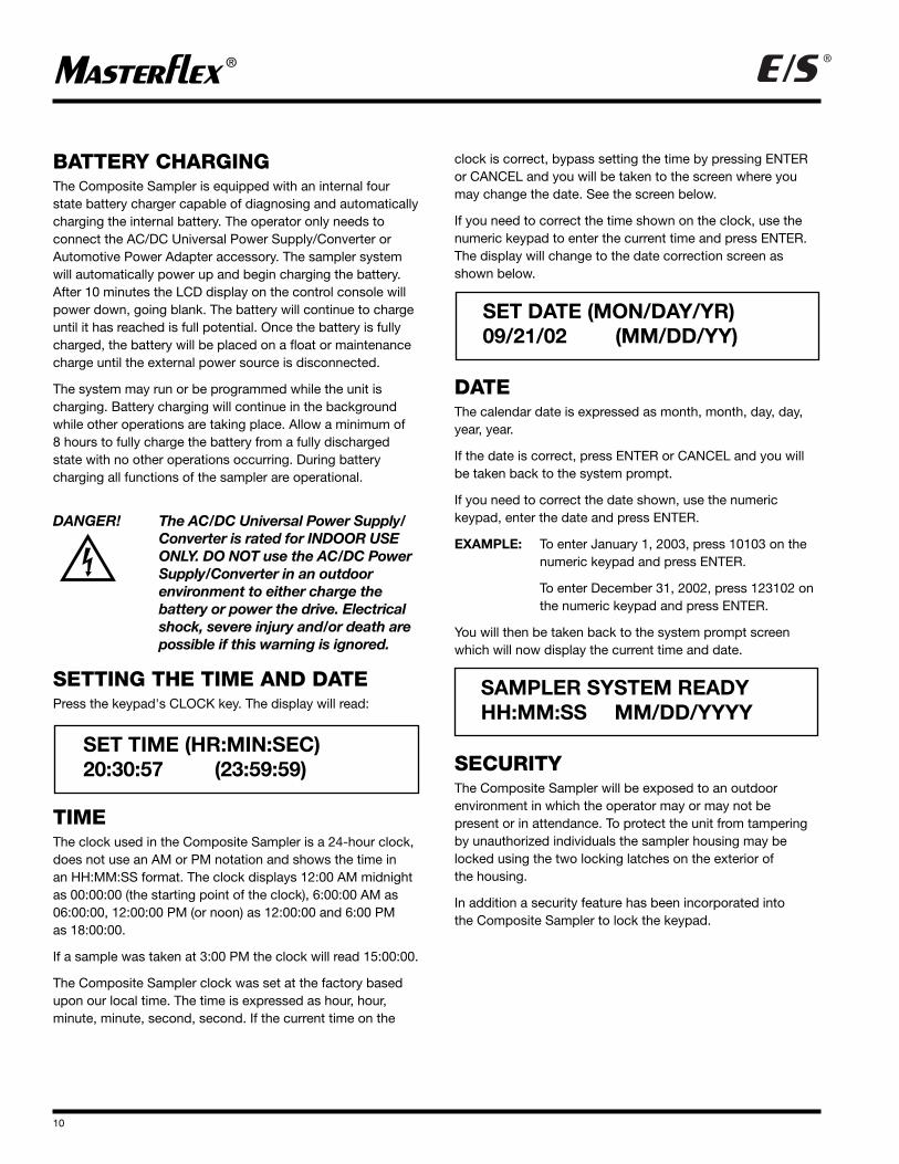
SETTING THE TIME AND DATEPress the keypad's CLOCK key. The display will read:
TIME The clock used in the Composite Sampler is a 24-hour clock,does not use an AM or PM notation and shows the time in an HH:MM:SS format. The clock displays 12:00 AM midnightas 00:00:00 (the starting point of the clock), 6:00:00 AM as06:00:00, 12:00:00 PM (or noon) as 12:00:00 and 6:00 PM as 18:00:00.
If a sample was taken at 3:00 PM the clock will read 15:00:00.
The Composite Sampler clock was set at the factory basedupon our local time. The time is expressed as hour, hour,minute, minute, second, second. If the current time on the
clock is correct, bypass setting the time by pressing ENTERor CANCEL and you will be taken to the screen where youmay change the date. See the screen below.
If you need to correct the time shown on the clock, use thenumeric keypad to enter the current time and press ENTER.The display will change to the date correction screen asshown below.
DATEThe calendar date is expressed as month, month, day, day,year, year.
If the date is correct, press ENTER or CANCEL and you willbe taken back to the system prompt.
If you need to correct the date shown, use the numeric keypad, enter the date and press ENTER.
EXAMPLE: To enter January 1, 2003, press 10103 on the numeric keypad and press ENTER.
To enter December 31, 2002, press 123102 on the numeric keypad and press ENTER.
You will then be taken back to the system prompt screenwhich will now display the current time and date.
SECURITYThe Composite Sampler will be exposed to an outdoor environment in which the operator may or may not be present or in attendance. To protect the unit from tamperingby unauthorized individuals the sampler housing may belocked using the two locking latches on the exterior of the housing.
In addition a security feature has been incorporated into the Composite Sampler to lock the keypad.
SET TIME (HR:MIN:SEC)20:30:57 (23:59:59)
SET DATE (MON/DAY/YR)09/21/02 (MM/DD/YY)
® ®
11
LOCKING THE KEYPADThe Composite Sampler keypad may be locked to ensurethat running programs are not inadvertently terminated or torestrict access to the system. The only key which is functionalwhen the keypad lockout is enabled is the 0-1/STATUS key.Pressing this key will not disable or interfere with any programwhich is running. To lock the keypad, perform the followingprocedure either from a system prompt or after you havepressed the START/STOP key to start a program. The keypadlockout cannot be enabled or disabled during programmingor the editing of a program.
1. Ensure that the control console is in a system ready promptor a program is running.
2. Enter 847 on the numeric keypad and press ENTER.
3. The following display appears for approximately five seconds. The display reappears anytime a non-numerickey is pressed and the LCD display is active.
4. To unlock the keypad, enter the same code and pressENTER. The following display appears:
OPERATIONThe unit is operated through the use of a menu system andvarious hot buttons on the keypad located on the control console face. The menus and their options are shown as wordsand numbers used in everyday oral communications orspeech without the need for decryption or an additional legend.
This equipment should not be operated on a "learn as yougo" basis. Make sure to become familiar with and practice allsafety procedures presented in the SAFETY section beforeoperating the Composite Sampler.
DESCRIPTION OF PROGRAMMINGThe Composite Sampler can be operated using any of the six (6) factory supplied programs through the menu system.
The five (5) sampling programs can be modified or edited andstored for future use. Editing the factory supplied programsand saving them as modified programs will temporarily overwrite the factory program. The factory programs can beindividually restored to their original default settings uponoperator demand through the menu system.
NOTE: One program is always present or selected to runwhenever the unit is on. When received from the factory thedefault program selected to be run is PROGRAM #1.
STARTING/STOPPING A PROGRAMTo start or stop a program press the START/STOP key.Programs can only be started from a SAMPLER SYSTEMREADY prompt. Sampling programs can be stopped at anytime the display is active by pressing CANCEL. If the displayis inactive, press the 0-1/STATUS key to awaken the systemand then press CANCEL. The CONTINUOUS PUMPING program can be stopped at any time. Stopping a program isequivalent to canceling the program. Programs that havebeen stopped cannot be restarted from the point at whichthey were stopped. When you start the program again, it willbegin at the beginning of the program.
HINT: If the program you stopped was taking a sample, itmay be necessary to empty or clear the sample reservoir prior to starting the program again.
CANCELING A PROGRAM To cancel a program that has started, press the CANCEL key. Canceling a program is the same as stopping a programas described above. Pressing the CANCEL key does not deselect the program selected to be run. It only cancels theprogram schedule that has started.
HINT: The program will show up on the data log as a cancelledprogram. If you do not want this record to appear on the datalog, clear the data log prior to starting the program again.
ACCESSING THE MENUOperation of the system and editing programs is menu driven.To access the menu press the MENU button on the controlconsole. The LCD display will show the following.
KEYPAD LOCKOUT ENABLED
KEYPAD LOCKOUT DISABLED
� GLOBAL SETTINGS� VIEW/EDIT PROGRAMS
12
®®
MENU The menu is divided into two main sections or categories: GLOBAL SETTINGS and VIEW/EDIT PROGRAMS.
GLOBAL SETTINGSThis section consists of operational parameters related to theComposite Sampler system as follows:
• DISPLAY CONTRAST
• SAMPLING LOCATION NUMBER
• PUMP HEAD SELECTION
• TUBING SIZE SELECTION
• TUBING FORMULATION SELECTION
• RINSE CYCLES
• VOLUME UNITS
• DISTANCE UNITS
• LIFT HEIGHT
• TUBING LENGTH
• LCD BACKLIGHTING
• DATA LOGGING
• DEFAULT GLOBAL SETTINGS
VIEW/EDIT PROGRAMSThe VIEW/EDIT PROGRAMS section consists of parametersrelated to the sampling programs as follows:
• SELECT HOW PROGRAM IS STARTED
• SAMPLE VOLUME
• NUMBER OF SAMPLES
• TIME INTERVAL BETWEEN SAMPLES EQUAL OR UNEQUAL
• # OF CONTACT CLOSURES
• DEFAULT THE PROGRAM SETTING
• SAVE USER PROGRAM
See Table #3 for menu categories and selections.
®
TABLE #3 MENU SELECTIONSDefaults are shown in BOLD type or noted
13
®
CATEGORY SELECTION CHOICES SUB SELECTIONS
DISPLAY CONTRAST UP & DOWN ARROWS TO ADJUST
LOCATION NUMBER ENTER 0-99999999
PUMP HEAD
EASY-LOAD/Standard
SIZE 24 TYGON LFLTYGON LAB
SIZE 15SILICONE TUBINGPHARMED BPT TUBING
PTFE TUBING PUMPPTFE 4 MM
PTFE 6 MM
RINSE CYCLES ENTER NUMBER 0-5 Default is 0
VOLUME UNITSMILLILITERS
GALLONS
DISTANCE UNITSFEET
GLOBALMETERS
LIFT HEIGHT ENTER NUMBER Default is 6 feet or 1.8 meters
TUBING LENGTH ENTER NUMBER Default is 12 feet or 3.6 meters
# OF CONTACT CLOSURESENTER NUMBER Only appears if MAINTAINED is not (0-9999) Default is 0 chosen under PROGRAM START/REMOTE & DELAYED START
DEFAULT PROGRAM RESET PROGRAM SETTINGSSETTINGS DON'T RESET SETTINGS
USER PROG #1
USER PROG #2
SAVE USER PROGRAM USER PROG #3
USER PROG #4
USER PROG #5
14
®®
NAVIGATIONLooking at the LCD display screen below:
1. The MENU key takes you to the top level of the menu asshown above.
2. The arrows in the first display column indicates which waythe user can go from each menu selection.
3. Solid box in second column indicates selected menu item,empty box is an unselected menu item.
NOTE: Only one selection is allowed in each menu option.
4. UP/DOWN arrow keys on the control console move thesolid box to select a menu item and scroll the display ifmore menu items are available.
5. The ENTER key accepts the selected item and movesdown to the next menu level. If there is not a lower menulevel, it will return to the top level for the selected item. Forexample, if selecting a tubing material, pressing ENTER willreturn back to the PUMP HEAD menu selection.
6. CANCEL key cancels any changes that were made to thecurrent menu selection and returns to previous menu.
7. CANCEL key will back up to previous menu level and exitthe menus when at the top level.
8. Display is 2 lines by 24 characters so only 2 lines of themenu are seen at one time.
GLOBAL SETTINGSGENERALThe GLOBAL SETTINGS are not saved in memory like multiple sampling programs. The only settings available arethose currently loaded into the non-volatile memory.
Selecting a menu option or setting using the up and downarrow keys does not load that option or setting in memoryuntil the ENTER key is pressed.
Settings must be modified as necessary to suit the samplingsite and equipment used. Many of these settings may use thedefault values, such as Pump Head selection, tubing size orformulation. Other parameters such as lift height and tubinglength or location will vary with the sampling site and will bechanged frequently.
GLOBAL SETTINGS TOURThe tour of the GLOBAL SETTINGS menu will take the operatorthrough each of the menu selection display screens. Goingthrough the entire menu is not necessary each time a changeto one or two GLOBAL SETTINGS parameters is made. It isrecommended that you take the tour to familiarize yourselfwith all of the options and screens available.
Select GLOBAL SETTINGS by pressing the ENTER key.
The display will now show the following choices:
Display ContrastAllows adjustment of the display contrast for readability.
Adjusting the Display ContrastTo adjust the contrast of the LCD display, select DISPLAYCONTRAST and press the ENTER key. The following menuwill be displayed:
View the display and use the up and down arrow keys toadjust the contrast. Press the up arrow key to increase contrast or the down arrow key to decrease contrast. Whenyou have achieved the desired contrast, press the ENTERkey. This will save the contrast setting you have selected for the display. The system will return you to the following display.
DISPLAY CONTRAST
� DISPLAY CONTRAST� LOCATION NUMBER
� GLOBAL SETTINGS� VIEW/EDIT PROGRAMS
� DISPLAY CONTRAST� LOCATION NUMBER
� GLOBAL SETTINGS� VIEW/EDIT PROGRAMS
15
®®
Use the down arrow to select LOCATION NUMBER, the filledin box will switch from DISPLAY CONTRAST to LOCATIONNUMBER and press ENTER. The display will change to read:
Location NumberAllows the input of up to a 9 digit number to identify the sampling site. You do not have to erase or delete the number(site identifier) that may already be there.
Inputting a Location NumberEnter the number and press ENTER. The new site identification number will be entered and the display willchange to:
Use the down arrow to decrement the menu to and selectPUMP HEAD by pressing ENTER.
The display changes to read:
Pump HeadMultiple option screens which allow the operator to select thePump Head, tubing size and tubing formulation or material.
EASY-LOAD is the default Pump Head supplied with theComposite Sampler for your convenience in changing thetubing when needed. If you intend to use the Pump Headsupplied with the unit press ENTER.
If you wish to use a PTFE TUBING PUMP proceed to thedescription of this menu option on page 16.
The display will change to read:
Size 24 is the default tubing size. The tubing supplied withthe Composite Sampler is L/S® 24 peroxide-cured siliconeModel No. 96400-24. This tubing size will deliver an averageflow of 1,700 ml/min. @ 0 lift.
Size 15 is an alternate tubing size offered for use with theEASY-LOAD Pump Head supplied with the CompositeSampler. This size option is offered for circumstances wherethe use of L/S® 24 in certain formulations may not be practical.The average flow of L/S® 15 tubing is 1,000 ml/min. @ 0 lift.
Select the appropriate tubing size and press the ENTER key.The display will change to the tubing formulation menu.
NOTE: The display is only 2 lines, so you will only see 2choices at one time. Remember the arrow in the first columnindicates whether there are choices above or below the onesyou are viewing.
The tubing formulations shown are available in either SIZE 24 or SIZE 15. See Table 1 Tubing Materials in theSETUP section of this manual for tubing model numbers.
LOCATION NUMBER_ _ _ _ _ _ _ _ _ (0-999999999)
� DISPLAY CONTRAST� LOCATION NUMBER
� LOCATION NUMBER� PUMP HEAD
� EASY-LOAD/STANDARD� PTFE TUBING PUMP
� SIZE 24� SIZE 15
� TYGON LFL TUBING� TYGON LAB TUBING
� SILICONE TUBING� PHARMED
16
®®
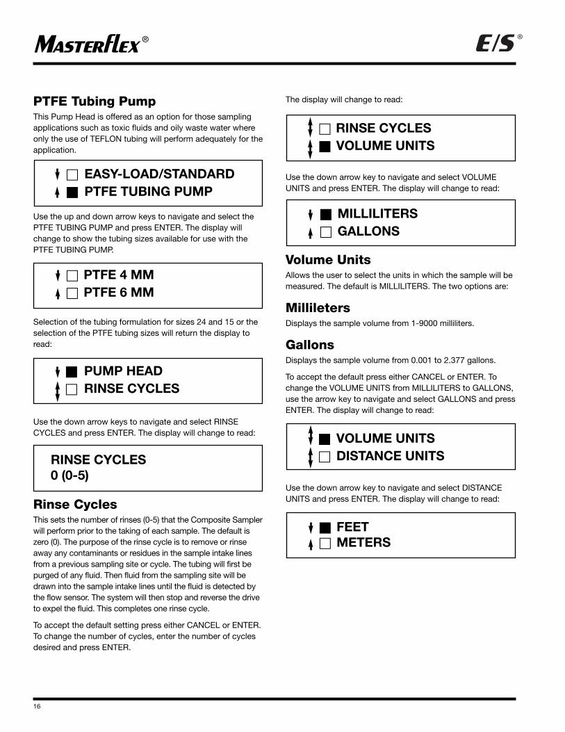
PTFE Tubing PumpThis Pump Head is offered as an option for those samplingapplications such as toxic fluids and oily waste water whereonly the use of TEFLON tubing will perform adequately for theapplication.
Use the up and down arrow keys to navigate and select thePTFE TUBING PUMP and press ENTER. The display willchange to show the tubing sizes available for use with thePTFE TUBING PUMP.
Selection of the tubing formulation for sizes 24 and 15 or theselection of the PTFE tubing sizes will return the display toread:
Use the down arrow keys to navigate and select RINSECYCLES and press ENTER. The display will change to read:
Rinse CyclesThis sets the number of rinses (0-5) that the Composite Samplerwill perform prior to the taking of each sample. The default iszero (0). The purpose of the rinse cycle is to remove or rinseaway any contaminants or residues in the sample intake linesfrom a previous sampling site or cycle. The tubing will first bepurged of any fluid. Then fluid from the sampling site will bedrawn into the sample intake lines until the fluid is detected bythe flow sensor. The system will then stop and reverse the driveto expel the fluid. This completes one rinse cycle.
To accept the default setting press either CANCEL or ENTER.To change the number of cycles, enter the number of cyclesdesired and press ENTER.
The display will change to read:
Use the down arrow key to navigate and select VOLUMEUNITS and press ENTER. The display will change to read:
Volume UnitsAllows the user to select the units in which the sample will bemeasured. The default is MILLILITERS. The two options are:
Millileters Displays the sample volume from 1-9000 milliliters.
GallonsDisplays the sample volume from 0.001 to 2.377 gallons.
To accept the default press either CANCEL or ENTER. Tochange the VOLUME UNITS from MILLILITERS to GALLONS,use the arrow key to navigate and select GALLONS and pressENTER. The display will change to read:
Use the down arrow key to navigate and select DISTANCEUNITS and press ENTER. The display will change to read:
� PTFE 4 MM� PTFE 6 MM
� PUMP HEAD� RINSE CYCLES
RINSE CYCLES0 (0-5)
� EASY-LOAD/STANDARD� PTFE TUBING PUMP
� RINSE CYCLES� VOLUME UNITS
� MILLILITERS� GALLONS
� VOLUME UNITS� DISTANCE UNITS
� FEET� METERS
17
®®
Distance UnitsAllows the user to select English or metric distance measurementunits. The default is feet.
The two options are:
FeetDisplays the VERTICAL LIFT (1-25) and TUBING LENGTH (1-99) in whole feet.
MetersDisplays the VERTICAL LIFT (0.3-7.6) and TUBING LENGTH(.3 to 30.1) in tenths of a meter.
To accept the default press either CANCEL or ENTER. Tochange the DISTANCE UNITS from FEET to METERS, use thearrow key to navigate and select METERS and press ENTER.The display will change to read:
Use the down arrow key to navigate and select LIFT HEIGHTand press ENTER. The display will change to read:
Lift HeightSets the draw or lift height to which the sample must be liftedto enter the sample reservoir.
This parameter allows the system to accurately calculate thesample volume for each revolution of the Pump Head at aspecific height. Sample volume decreases as lift heightincreases. This parameter will be expressed in feet or metersdepending upon your earlier choice of DISTANCE UNITS. Thedefault is 6 feet or 1.8 meters. Enter the number and pressenter. The acceptable values will be shown in parenthesis onthe 2nd line on the right side of the display.
Once you press enter the display will change to:
Use the down arrow key to navigate and select TUBINGLENGTH and press ENTER. The display will change to read:
Tubing LengthSets the length of tubing through which the sample volumemust be drawn. Setting the tubing length allows the system to calculate the correct amount of time for purging the tubingprior to taking a sample. This parameter will be expressed infeet or meters depending upon your earlier choice of DISTANCEUNITS. The default is 12 feet or 3.6 meters. Enter the numberand press enter. The acceptable values will be shown in parentheses on the second line on the right side of the display.
Once you press enter the display will change to:
Use the down arrow key to navigate and select LCD BACK-LIGHT and press ENTER. The display will change to read:
NOTE: The display is only 2 lines, so you will only see 2choices at one time. Remember the arrow in the first columnindicates whether there are choices above or below the onesyou are viewing.
LCD BacklightSets the conditions under which the display is backlit for optimum readability. There are four choices of backlighting.
LIFT HEIGHT6 FEET (0-25)
� LIFT HEIGHT� TUBING LENGTH
� DISTANCE UNITS� LIFT HEIGHT
TUBING LENGTH12 FEET (1-99)
� TUBING LENGTH� LCD BACKLIGHT
� NONE—POWER SAVER� BACKLIGHT ON KEY PRESS
� KEY PRESS AND SAMPLING� CONTINUOUS BACKLIGHT
18
®®
NONE—Power SaverThe display will not be backlit under any circumstance. This is the default setting and is used to conserve power. If theLCD display can be read without difficulty in the samplingenvironment, then this is adequate.
Backlight on Key PressThe LCD will be backlit for 10 seconds when any key ispressed. After 10 seconds the display will return to its normalunlit state. This setting can be useful during programmingsince it improves the readability of the display without wast-ing power and provides backlighting during programming orselecting menu options in low ambient light conditions.
Key Press and SamplingThe LCD will be backlit for 10 seconds when any key ispressed or whenever a sample is to be taken. Ten (10) seconds after the last key is pressed or after the samplingcycle is completed the display will return to its normal unlitstate. This setting can be useful during programming since itimproves the readability of the display and allows monitoringof the sampling process in low ambient light conditions. If the Composite Sampler will be left unattended during thesampling process this setting is not recommended.
Continuous BacklightThe LCD will always be backlit as long as the display is active.
HINT: The system's automatic power conservation feature blanksthe LCD display if no key has been pressed for 10 minutes.
Blanking of the LCD also occurs 10 seconds after the systemhas taken a sample or processed an internal instruction whilerunning a program. See the FAMILIARIZATION WITH SYSTEM FEATURES section on page 7.
It is recommended that you experiment with the variousbacklighting options to determine your preference. You canalways return to the menu option by pressing ENTER onceyou have made your selection and pressed ENTER, becausethe display will change to read:
Proceeding down the menu, use the down arrow key to navigate and select the next menu option LOG DATA andpress ENTER. The display will change to read:
HINT: The display is only 2 lines, so you will only see 2choices at one time. Remember the arrow in the first columnindicates whether there are choices above or below the onesyou are viewing.
Log DataThe system logs all events, such as: sample location, cycledate and time, sample volume, and any faults which mayoccur during the sampling process. The system is capable oflogging 300 events. This log is stored in non-volatile memoryoutside of the DSP. This log may be viewed or printed.Viewing or printing the log does not erase or clear the logfrom memory. The log may only be erased through the use ofthe CLEAR LOG DATA menu option.
NOTE: Should you forget to clear the logged data, the systemwill begin to overwrite the oldest data first. This occurs onlyonce the capacity of the non-volatile memory log has beenexceeded.
View Log DataAllows the user or operator to view the data log. This doesnot erase or clear the data log.
This is the default option for LOG DATA.
Print Log DataAllows the printing of the data log. This menu option requiresthe use of the RS-232 cable assembly catalog no. 07580-65.See the ACCESSORY section for details. Printing of the datalog does not erase or clear the data log.
� LCD BACKLIGHT� LOG DATA
� VIEW LOG DATA� PRINT LOG DATA
� PRINT LOG DATA� CLEAR LOG DATA
19
®®
Clear Data LogAllows the operator to clear the data log. This is the only waythe data log may be cleared or erased. Once you haveselected the menu option and pressed ENTER, you will betaken to a confirmation screen as shown below:
The default selection will not clear the data log. You must usethe up arrow to select "CLEAR ALL LOG DATA" and pressENTER. Once the ENTER key has been pressed, the log willbe erased and the display will change to read:
Use the down arrow key to navigate and select DEFAULTGLOBAL SETTINGS and press ENTER. The display willchange to read:
Default Global SettingsAllows the operator to return all of the GLOBAL SETTINGS totheir default values.
If you have made changes to the GLOBAL SETTINGS andlost track of the changes you have made or would just like tostart your changes from some common point, this option willprove to be helpful. This option allows resetting of theGLOBAL SETTINGS without having to track your changes orremember what the default was.
To reset the GLOBAL SETTINGS you must use the up arrowkey to navigate and select RESET GLOBAL SETTINGS andpress ENTER. This confirmation of your selection to return thesettings to their default value is done to prevent accidental orunintended changes to the global settings. Once you pressthe enter key your previous changes will be lost and cannotbe recovered.
HINT: To exit the menu and return to a system ready promptuse the cancel key.
Hot KeyOne option of the GLOBAL SETTINGS menu is also accessiblevia a "Hot Key" located on the control console keypad. Thekey is round, blue in color and labeled LIFT HEIGHT. This keyallows the operator to access the lift height setting in theGLOBAL SETTINGS without going through the menu.
VIEW/ EDIT PROGRAMSGENERALThere are a total of 6 programs supplied with the CompositeSampler. One program is a fluid transfer program called CONTINUOUS PUMPING, this program cannot be modified.The other 5 programs are fluid sampling programs. Theseprograms are numbered 1 through 5. All programs can beaccessed through the menu system of the CompositeSampler. The 5 sampling programs can be edited to createyour own sampling programs. Edited or modified programsmust be saved before they can be run. Modifying the factorysupplied programs and saving them as modified programswill temporarily overwrite the factory program. The factoryprograms can be individually restored to their original defaultsettings upon demand.
Only (1) one program can be loaded and used at a time. Aprogram is always loaded into memory of the CompositeSampler.
PROGRAM MENU TOUROperation of the system is menu driven. To access the menu,if not presently displayed, press the MENU button on thecontrol console. The LCD display will show the following.
Use the down arrow key to navigate and select VIEW/EDITPROGRAMS and press ENTER. The display will change to read:
HINT: The display is only 2 lines, so you will only see 2choices at one time. Remember the arrow in the first columnindicates whether there are choices above or below the onesyou are viewing.
� CLEAR ALL LOG DATA� DON’T CLEAR ALL LOG DATA
� LOG DATA� DEFAULT GLOBAL SETTINGS
� RESET GLOBAL SETTINGS� DON’T RESET SETTINGS
� GLOBAL SETTINGS� VIEW/EDIT PROGRAMS
� PROGRAM #1� PROGRAM #2
20
®®
Navigate further into the program options by using the ¼down arrow key.
Loaded ProgramsOne of the available programs is always loaded into the memory for use. How do you verify which program is loadedfor operation of the Composite Sampler? To verify which program is loaded for operation of the unit, access the menuby pressing the MENU key and selecting VIEW/EDIT PROGRAMS, then press the ENTER key.
The display will change to show 2 program options. One ofthese options will show a darkened or filled in box next to theprogram name. This is the program which is loaded for operation.
See the example below.
In this case PROGRAM #3 is loaded for operation as shownin the above example.
Continuous PumpingThis program is for fluid transfer in the field. The pump willstart when the START/STOP button is pressed or the REMOTECONTACT CLOSURE is closed. The pump will stop when the same button is pressed again, the REMOTE CONTACTCLOSURE opens or the fluid level sensor in the sample reservoir causes the system to stop because the reservoir is full. This program cannot be modified in any manner. This program selection is not visible when you first access the program menu. Select VIEW/EDIT PROGRAMS and pressENTER. The display will change to read as follows.
The arrow at the far left of the display on line 1 shows a bi-directional arrow, indicating there is an available optionabove PROGRAM #1.
Use the up arrow key to navigate upward in the menu. Thedisplay will change to read:
You may now select CONTINUOUS PUMPING by pressingthe ENTER key.
� PROGRAM #2� PROGRAM #3
� PROGRAM #3� PROGRAM #4
� PROGRAM #4� PROGRAM #5
� PROGRAM #3� PROGRAM #4
� PROGRAM #1� PROGRAM #2
� CONTINUOUS PUMPING� PROGRAM #1
21
®®
SAMPLING PROGRAMS #1-5The attached summary shows the default values for the 5 factory sampling programs
PARAMETER PROGRAM 1 PROGRAM 2 PROGRAM 3 PROGRAM 4 PROGRAM 5
PROGRAM START
DELAYED START HR:MIN 0-167:59 00:00 01:00
REMOTE & DELAYED START 00:00 167:59 01:00
MAINTAINED CONTACT X X
PULSED CONTACT X
SAMPLE VOLUME 1-9000ml 500 500 375 500 375
NUMBER OF SAMPLES 1-99 18 12 24 18 24
TIME BETWEEN SAMPLES
EQUAL INTERVALS HH:MM 00:15 00:00 01:00 01:00
UNEQUAL INTERVALS HH:MM X
#1 00:15
#2 00:30
#3 00:45
#4 01:00
#5 01:15
#6 01:30
#7 01:45
#8 02:00
#9 02:15
#10 02:30
#11 02:45
#12 03:00
# OF CONTACT CLOSURES 0 Not Visible 5 0 Not Visible
22
®®
SAMPLING PROGRAMMENU OPTIONSGENERALAll of the sampling programs have the same menu options.Programs are constructed or built by editing the existing program sampling menu options and saving those changesas a modified program. The sampling menu options areaccessed through any of the sampling programs, shown inthe VIEW/EDIT PROGRAMS menu. Select a sampling program such as PROGRAM #1 and press the ENTER key.The display will change to read:
NOTE: You may make only one selection in each menuoption.
Select PROGRAM START and press ENTER. The display will change to read:
PROGRAM STARTAllows the operator to change how the program starts: immediately, with a delay or through the use of anotherdevice. There are two options; DELAYED START andREMOTE & DELAYED START.
Select DELAYED START and press ENTER: The display willchange to:
Delayed StartAllows the operator to input the time delay for starting theprogram once the START button is pressed. The parameter ishours and minutes 0-167:59. If you want the program to startimmediately upon pressing the START button input 0 andpress ENTER. To start after a delay or waiting period input the desired time. If the desired delay time is 40 hours and 0 minutes input 4000 and press enter. If the desired time is 5 minutes of delay time input 5 and press enter.
Remote & Delayed Start Allows the operator to start the Composite Sampler throughthe use of another instrument using the REMOTE CONTACTCLOSURE (see Figure 2) located on the exterior right handside of the unit. The other instrument must be able to eitherclose or short the contacts (dry contact closure) or generate apulse. Some of the instruments or devices that may be usedto start the Composite Sampler remotely are: level sensors orfloat switches, pH meters or flowmeters.
Using the remote start component of this feature you cansample a water source upon the occurrence of an event suchas a rain storm or increase in water flow or pH.
The delayed start component of this feature allows the operatorto add a time delay once the contact closure or remote signalhas activated the unit. This feature can be used to delay thestart of a sampling program until an event causes the watersource being sampled to change. An example of this wouldbe a rainstorm upstream of a water source. It may take 15minutes before the water from the rainstorm affects the watersource you are sampling. You do not want to sample the water source until it is affected by the incomingwater. You can use a float or level switch to sense an increaseof water level and remotely turn on the Composite Samplerand the time delay to cause the program to wait before takingthe first sample to allow the waters to mix. The use of thisfeature requires the Remote Contact Closure AccessoryModel No. 7580-60.
See the ACCESSORY section for details.
When you select REMOTE & DELAYED START and pressENTER, the display changes to:
� PROGRAM START� SAMPLE VOLUME
� DELAYED START� REMOTE & DELAYED START
DELAYED START000:00 HR/MN (0-167:59)
DELAYED START000:00 HR/MN (0-167:59)
23
®®
Maintained ContactThis is the default type of signal that is continuous or level related.There is continuous continuity between the contacts, like a short.When this option is selected the REMOTE CONTACT CLOSUREmust remain closed during the entire sample program. If theREMOTE CONTACT CLOSURE should open during the program; theprogram will stop after taking the next scheduled sample.
Pulsed ContactThis type of signal is not continuous. It goes on and off andthe system is able to count the number of pulses or signals toperform various functions.
Select the appropriate type of contact using the arrow keysand press ENTER. The display will return you to:
Use the down arrow key to navigate and select SAMPLEVOLUME and press ENTER. The display will change to read:
SAMPLE VOLUMEAllows the operator to enter the desired sample volume.
Volume units that were selected in the GLOBAL SETTINGSmenu option is what will appear. If you selected gallons, thenGAL (representing gallons) will appear on the display screen.
The minimum sample volume that can be taken will vary withtubing size. Trying to pump a 1 mL sample with L/S® 24 sizetubing is not practical. Use smaller tubing for pumpingsmaller sample volumes. See the SPECIFICATION section forthe minimum volume required for calibration accuracy.
HINT: If you will be taking small sample volumes such as 100mL and or require high lifts greater than 12 feet than you
should consider using L/S® 15 size tubing. This will improvethe performance and accuracy of the sample volume taken.
Enter the desired sample volume and press ENTER. The display will return you to:
Use the down arrow key to navigate and select NUMBER OFSAMPLES and press ENTER. The display will change to read:
Number of SamplesAllows the operator to set the number of samples to be taken. Select NUMBER OF SAMPLES and press ENTER. The display will change to read:
HINT: If the number of samples times the sample volumeexceeds the reservoir capacity you will receive an error message asking you to decrease one or the other when youtry to save the program. You must correct the problem beforeyou can save the program.
After entering the NUMBER OF SAMPLES press ENTER. Thedisplay will return you to:
Use the down arrow key to navigate and select TIMEBETWEEN SAMPLES and press ENTER.
� MAINTAINED CONTACT� PULSE CONTACT
� PROGRAM START� SAMPLE VOLUME
SAMPLE VOLUME500 ML (1-9000)
� PROGRAM START� SAMPLE VOLUME
� SAMPLE VOLUME� NUMBER OF SAMPLES
NUMBER OF SAMPLESXX (1-99)
� SAMPLE VOLUME� NUMBER OF SAMPLES
� NUMBER OF SAMPLES� TIME BETWEEN SAMPLES
24
®®
Time Between SamplesAllows the operator to input the desired time between samples.When TIME BETWEEN SAMPLES is selected and you pressENTER two choices will presented for your selection.
Equal IntervalsAllows the operator to input the desired time between samplesin an hours:minutes format. All time intervals will be the sameor equal. You can select any time period between 0 minute to99 hours 59 minutes. The time for this option should be set to a value greater than 0 except for applications where thenumber the # CONTACT CLOSURES is chosen to control timebetween samples. The display appears as follows:
NOTE: If your are using the # CONTACT CLOSURES menuoption the time in this option should be set to 00:00 HR:MN,otherwise the two features will interact. This will cause thetimer to enact a sampling cycle rather than the set number ofcontact closures if the time interval occurs before the # OFCONTACT CLOSURES..
Unequal IntervalsAllows the operator to input desired time between samples in an hours:minutes format where the time between samplescan vary. The operator is allowed a maximum of 12 differenttime periods between samples. If more than 12 samples wereselected in NUMBER OF SAMPLES menu option the remainingtime periods will repeat time period #12.
If only 5 samples were selected in NUMBER OF SAMPLESonly 5 time periods will appear in the selection menu. The dis-play appears as follows:
HINT: The display is only 2 lines, so you will only see 2choices at one time. Remember the arrow in the first columnindicates whether there are choices above or below the onesyou are viewing.
Once you have made your selections and pressed enter thedisplay changes to read:
Use the down arrow key to navigate and select # OF CONTACTCLOSURES and press ENTER. The display changes to read:
# OF CONTACT CLOSURESThis menu option will not be visible if you selected REMOTE &DELAYED START in the PROGRAM START option and selectedthe MAINTAINED CONTACT menu option. The system will bestarted by a single contact closure. The system will be take asample after the specified number of contact closures occurs.
The number of contact closures available is 0-9999. Thedefault is 0.
Once you have made your selections and pressed enter thedisplay changes to read:
Use the down arrow key to navigate and select DEFAULTPROG SETTINGS and press ENTER.
� EQUAL INTERVALS� UNEQUAL INTERVALS
EQUAL INTERVALS00:15 HR:MN (0-99:59)
� #1 00:15 HR:MN� #2 00:30 HR:MN
� #2 00:45 HR:MN� #3 01:00 HR:MN
� #11 02:45 HR:MN� #12 03:00 HR:MN
� TIME BETWEEN SAMPLES� # OF CONTACT CLOSURES
# OF CONTACT CLOSURES(0-9999)
� TIME BETWEEN SAMPLES� DEFAULT PROG SETTINGS
25
®®
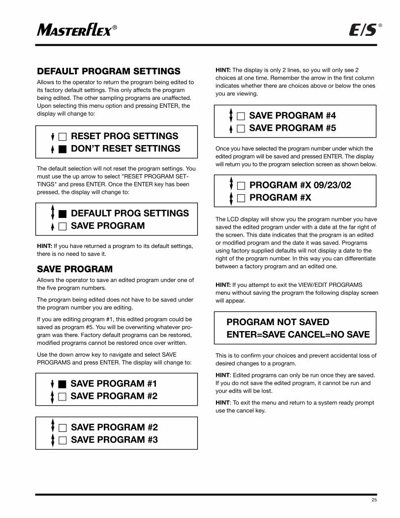
DEFAULT PROGRAM SETTINGSAllows to the operator to return the program being edited toits factory default settings. This only affects the programbeing edited. The other sampling programs are unaffected.Upon selecting this menu option and pressing ENTER, thedisplay will change to:
The default selection will not reset the program settings. Youmust use the up arrow to select "RESET PROGRAM SET-TINGS" and press ENTER. Once the ENTER key has beenpressed, the display will change to:
HINT: If you have returned a program to its default settings,there is no need to save it.
SAVE PROGRAMAllows the operator to save an edited program under one ofthe five program numbers.
The program being edited does not have to be saved underthe program number you are editing.
If you are editing program #1, this edited program could besaved as program #5. You will be overwriting whatever pro-gram was there. Factory default programs can be restored,modified programs cannot be restored once over written.
Use the down arrow key to navigate and select SAVE PROGRAMS and press ENTER. The display will change to:
HINT: The display is only 2 lines, so you will only see 2choices at one time. Remember the arrow in the first columnindicates whether there are choices above or below the onesyou are viewing.
Once you have selected the program number under which theedited program will be saved and pressed ENTER. The displaywill return you to the program selection screen as shown below.
The LCD display will show you the program number you havesaved the edited program under with a date at the far right ofthe screen. This date indicates that the program is an editedor modified program and the date it was saved. Programsusing factory supplied defaults will not display a date to theright of the program number. In this way you can differentiatebetween a factory program and an edited one.
HINT: If you attempt to exit the VIEW/EDIT PROGRAMSmenu without saving the program the following display screenwill appear.
This is to confirm your choices and prevent accidental loss ofdesired changes to a program.
HINT: Edited programs can only be run once they are saved.If you do not save the edited program, it cannot be run andyour edits will be lost.
HINT: To exit the menu and return to a system ready promptuse the cancel key.
� RESET PROG SETTINGS� DON’T RESET SETTINGS
� DEFAULT PROG SETTINGS� SAVE PROGRAM
� SAVE PROGRAM #4� SAVE PROGRAM #5
� PROGRAM #X 09/23/02� PROGRAM #X
PROGRAM NOT SAVEDENTER=SAVE CANCEL=NO SAVE
� SAVE PROGRAM #1� SAVE PROGRAM #2
� SAVE PROGRAM #2� SAVE PROGRAM #3
26
®®
HOT KEYSThree of the VIEW/EDIT PROGRAMS menu options are alsoaccessible via "Hot Keys" located on the control console keypad. The keys are round, blue in color and labeled SAMP.VOL., TIME, and DELAY START. These keys allow the operatorto access the sample volume, time between samples anddelay starting time for the program currently selected to runwithout going through the menu.
HINT: To save the program setting you have just modifiedusing the HOT KEYS you must save the program or yourchange will be lost.
CALIBRATING THE SYSTEMGENERALThe Composite Samplers' non-volatile memory contains flowdata related to sample volume flow per Pump Head revolutionversus sample lift height. This information is used to calculatethe correct sample volume being taken by the system at aspecific lift height. Due to the number of variables and variations possible with use of the Composite Sampler in thefield, the stated accuracy of the unit is achieved only whenthe unit is calibrated at the field site after setup of the sampleras it will be used.
MINIMUM SAMPLE SIZEThe stated accuracy of the sample volume being taken ispredicated on a minimum sample size versus the tubing sizeused to take the sample.
For L/S® 15 size tubing the minimum sample size for statedcalibrated sample accuracy is 167 milliliters.
For L/S® 24 size tubing the minimum sample size for statedcalibrated sample accuracy is 270 milliliters.
REQUIRED EQUIPMENTTo calibrate the Composite Sampler you will need a graduatedcylinder with a minimum volume of 250ml for use with L/S® 15tubing or 500 mL for use with L/S® 24 tubing. The graduatedcylinder is not supplied with the sampler system and is theusers’ responsibility to provide one. See the ACCESSORIESsection for recommended graduated cylinders.
CALIBRATION PROCEDURE1. Setup the Composite Sampler on site as it will be used
for sampling.
2. Verify that the global settings for lift height and tubinglength have been entered.
3. Disconnect the sample hose from the sample reservoirquick disconnect fitting.
4. Have the graduated cylinder ready.
5. Press the CAL key.
The display will change to read:
6. Press the ENTER key and hold the sample hose to thegraduated cylinder.
7. The system will first purge the sample intake line and thentake a calibration volume. When the sample has completedtaking a calibration volume, the display will change to read:
8. Read the volume from the graduated cylinder and enter thevolume measured on the numeric keypad and press theENTER key. EXAMPLE: If the volume was 10.5 ml enter 105and press ENTER. If the measured volume was 267.5 mlenter 2675 and press ENTER.
9. The system will then return to a system ready prompt onthe LCD display.
� START TUBE CALIBRATIONUSING FACTORY CAL
ENTER MEASURED VOLUME_ _ _ . _ ML (1-999.9)
SAMPLER SYSTEM READYHH:MM:SS MM/DD/YYYY
27
®®
PREVIOUS CALIBRATIONSIf the Composite Sampler System was previously calibratedon another site, the recommendation is to restore the factorycalibration prior to calibrating the system at another site. Torestore the factory calibration press the CAL key. The displaywill change to read:
Use the down arrow key to navigate and select RESTOREFACTORY CAL and press ENTER. The Display will change torequest a confirmation of requested action and will read asshown below.
Navigate using the up arrow to select RESTORE FACTORYCAL and press ENTER.
The display will change to read as shown at the beginning ofthe calibration procedure.
CYCLING THE SYSTEMThe operational readiness of the system and sample lines can be checked prior to starting the sampling program. Theoperator can perform this check by:
1. Disconnecting the sample line from the sample reservoir at the quick disconnect fitting on the reservoir cap. Point theend of the sample line away from the unit.
2. Press CYCLE TEST key.
3. The unit will go through a through a purge cycle, a singlerinse cycle if one or more are programmed, and draw a single sample of the volume programmed.
4. Reconnect the sample line to the sample reservoir caponce you have completed this check.
MAINTENANCE
WARNING: Disconnect the Composite Samplefrom any external power sourcebefore cleaning. A shock hazardexists when using water on poweredequipment.
CLEANING: Keep the exterior housing and sample reservoir clean byusing a mild detergent and soap solution. Never immerse theunit in water or use excessive fluid when cleaning the system.Dry the cleaned parts before restoring external power.
SAMPLE RESERVOIR VENTSThe sample reservoir cap contains two breather vents allowing the reservoir to be filled with fluid, while expelling air. These vents can become clogged by particulate matterpresent in the fluid samples taken at various sites.
To clean the vents apply a vacuum source to the inside boreof the vent to remove any contaminants or foreign matter. Ifcleaning is unsuccessful in unclogging the vents, they willhave to be replaced.
Refer to USER REPLACEMENT PARTS for the part numbersof all user replacement parts.
TUBINGThe tubing will occasionally have to be replaced due to wearat the Pump Head and fouling.
The routing of the tubing is important, since it will change theperformance of the product if not performed correctly.
The correct routing of the tubing is as follows:
1. From the Sample Inlet bulkhead connector to the bottom ofthe Flow Detector. A tubing length of 18" is required.
2. From the top of the Flow Detector through the pump to theSample Reservoir. A tubing length of 17.63" is required.
� START TUBE CALIBRATION� USING FACTORY CAL
� RESTORE FACTORY CAL� DON’T RESTORE CAL
28
®®
Display Reads Descriptions and Remedies
BAD GLOBAL SETUP Global setup data from EEPROM corrupted, reset GLOBAL SETTINGS to their defaults.USING DEFAULTS
BAD USER CAL DATA User field cal Data from EEPROM corrupted,reset to factory cal.USING DEFAULTS
REAL TIME CLOCK ERROR Run data in RTC RAM corrupted, program running status lost. Charge or replace battery CHECK BATTERY as necessary.
BATTERY FULLY CHARGED During battery check, voltage under load Ž 12.5V.
BATTERY LOW During battery check, voltage under load < 12.5V. Strongly recommend you chargeCHARGING IS RECOMMENDED the battery. You may not have enough power to run a complete sampling program
sequence. Charge the battery.
BATTERY IS VERY LOW During battery check, voltage under load <11.9V. You must charge the battery! MUST CHARGE BATTERY! Damage to unit can result if run in a discharged state.
CAN'T CHARGE BATTERY Battery was in trickle charge state for over 4 hours (< 10.5V). Replace the battery.MUST REPLACE BATTERY
ERROR: NO BATTERY Detected battery voltage over 16V. Check battery connections. If connected, replaceMUST REPLACE BATTERY the battery. Contact factory for further assistance if needed.
BAD FLASH CHECKSUM Bad program checksum in flash. Operation of unit is disabled. Internal system problem. SERVICE REQUIRED Contact factory for assistance.
NO MOTOR FEEDBACK No encoder pulses detected. Internal system problem, contact the factory for assistance.SERVICE REQUIRED
MOTOR OVER SPEED Motor running too fast. If any servicing of the motor took place recently, the motor leadsSERVICE REQUIRED may have been reversed. Check that the polarity of the motor leads matches the coding
next to the terminal. Red lead to terminal marked red, black to black. Contact the factory for assistance if problem cannot be corrected.
MOTOR OVERLOAD Motor is stalled. Motor current is at maximum and battery is not low. Shutoff the CHECK TUBING Composite Sampler. Remove tubing from pump. Verify that the correct tubing size
and formulation listed by this manual is being used. Replace tubing in pump. Contact the factory for assistance if problem cannot be corrected.
SAMPLE RESERVOIR FULL Sample reservoir is full. Reservoir must be emptied before you can continue. Empty MUST EMPTY RESERVOIR reservoir, then press CANCEL to clear error message.
ERROR: The flow sensor still shows continuity indicating the presence of fluid. Check flow CHECK FLOW SENSOR sensor for fluid, by disconnecting upper tubing connection, then lower connection.
If fluid present, clear flow sensor of all fluid. Press CANCEL. If message persists contact factory for assistance.
NO FLOW DETECTED The flow sensor has not detected any fluid flow through the tubing. The sampleSERVICE REQUIRED inlet line may have become obstructed. Verify that the sample inlet line is not
blocked or obstructed, and check for a hole in the tubing. Contact the factory for assistance.
TROUBLESHOOTINGGENERAL
ERROR STATUS/MESSAGES AND SOLUTIONS
Message Types Various messages on the system's LCD display alert the operator to the condition of or possible problems with the system. Somecan be addressed by the operator, while other problems require factory servicing or assistance. Most problems that occur can becorrected by the operator on site. The following is a listing of messages their meaning and possible remedies if applicable:
29
®®
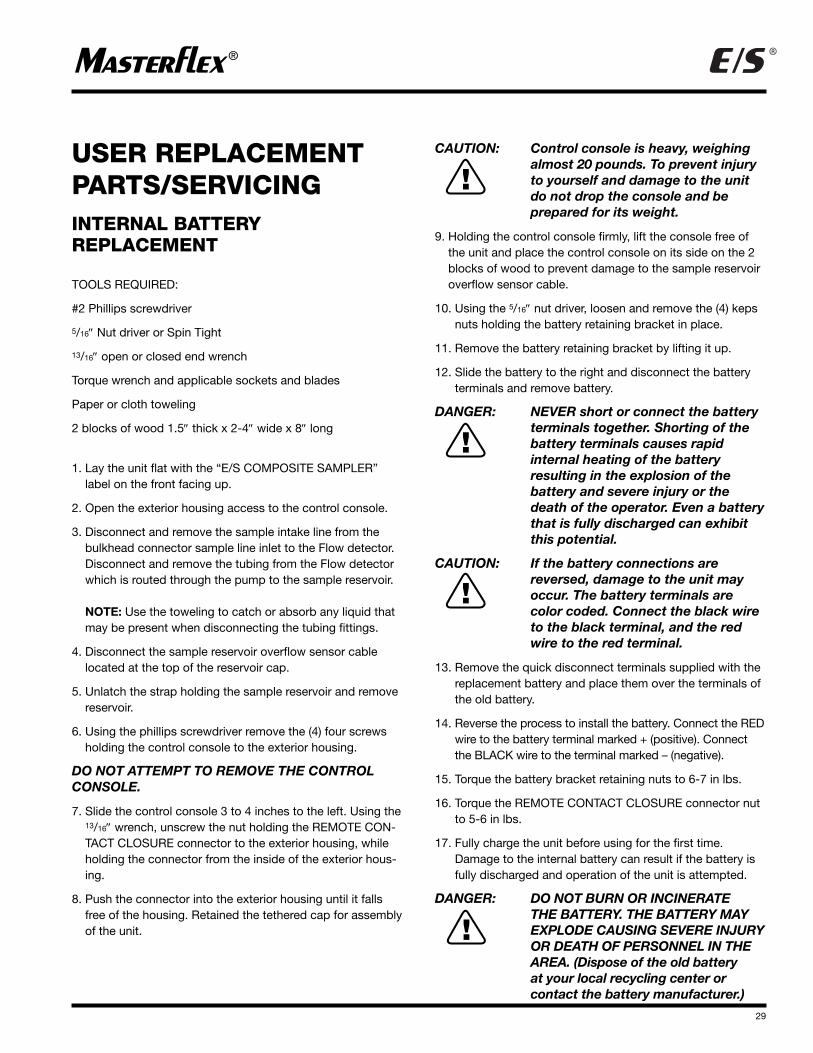
USER REPLACEMENTPARTS/SERVICINGINTERNAL BATTERY REPLACEMENT
TOOLS REQUIRED:
#2 Phillips screwdriver
5/16″ Nut driver or Spin Tight
13/16″ open or closed end wrench
Torque wrench and applicable sockets and blades
Paper or cloth toweling
2 blocks of wood 1.5″ thick x 2-4″ wide x 8″ long
1. Lay the unit flat with the “E/S COMPOSITE SAMPLER”label on the front facing up.
2. Open the exterior housing access to the control console.
3. Disconnect and remove the sample intake line from thebulkhead connector sample line inlet to the Flow detector.Disconnect and remove the tubing from the Flow detectorwhich is routed through the pump to the sample reservoir.
NOTE: Use the toweling to catch or absorb any liquid thatmay be present when disconnecting the tubing fittings.
4. Disconnect the sample reservoir overflow sensor cablelocated at the top of the reservoir cap.
5. Unlatch the strap holding the sample reservoir and removereservoir.
6. Using the phillips screwdriver remove the (4) four screwsholding the control console to the exterior housing.
DO NOT ATTEMPT TO REMOVE THE CONTROLCONSOLE.
7. Slide the control console 3 to 4 inches to the left. Using the13/16″ wrench, unscrew the nut holding the REMOTE CON-TACT CLOSURE connector to the exterior housing, whileholding the connector from the inside of the exterior hous-ing.
8. Push the connector into the exterior housing until it fallsfree of the housing. Retained the tethered cap for assemblyof the unit.
CAUTION: Control console is heavy, weighingalmost 20 pounds. To prevent injuryto yourself and damage to the unitdo not drop the console and be prepared for its weight.
9. Holding the control console firmly, lift the console free ofthe unit and place the control console on its side on the 2blocks of wood to prevent damage to the sample reservoiroverflow sensor cable.
10. Using the 5/16″ nut driver, loosen and remove the (4) kepsnuts holding the battery retaining bracket in place.
11. Remove the battery retaining bracket by lifting it up.
12. Slide the battery to the right and disconnect the batteryterminals and remove battery.
DANGER: NEVER short or connect the batteryterminals together. Shorting of thebattery terminals causes rapid internal heating of the battery resulting in the explosion of thebattery and severe injury or thedeath of the operator. Even a batterythat is fully discharged can exhibitthis potential.
CAUTION: If the battery connections arereversed, damage to the unit mayoccur. The battery terminals arecolor coded. Connect the black wireto the black terminal, and the redwire to the red terminal.
13. Remove the quick disconnect terminals supplied with thereplacement battery and place them over the terminals ofthe old battery.
14. Reverse the process to install the battery. Connect the REDwire to the battery terminal marked + (positive). Connectthe BLACK wire to the terminal marked – (negative).
15. Torque the battery bracket retaining nuts to 6-7 in lbs.
16. Torque the REMOTE CONTACT CLOSURE connector nutto 5-6 in lbs.
17. Fully charge the unit before using for the first time.Damage to the internal battery can result if the battery isfully discharged and operation of the unit is attempted.
DANGER: DO NOT BURN OR INCINERATE THE BATTERY. THE BATTERY MAYEXPLODE CAUSING SEVERE INJURYOR DEATH OF PERSONNEL IN THEAREA. (Dispose of the old battery at your local recycling center or contact the battery manufacturer.)
30
®®
USER REPLACEMENTPARTS
77200-07 AC/DC Universal Power Supply/Converter100-240V AC
77500-03 Fuse, Automotive Power Adapter orAuxiliary Power Pack
07571-55 Battery 12V 7.2AH
06360-82 Sample Line Tubing Connector, Quick Connect
06361-46 Bulkhead Connector, Sample Line Quick Connect
Speed: 600 rpm with EASY-LOAD Pump Head300 rpm with PTFE Pump Head
Maximum continuous torque: 30-in oz. (212 N•mm)Speed regulation: +/- 1 RPM
Input:Supply voltage limits:
115V AC 90V AC to 130V AC, 47-63 Hz230V AC 180V AC to 260V AC,
47-63 Hz12V DC 11-18V DC
Nominal Current:115V AC 120 mA230V AC 60 mA12V DC 2.0 A
Installation category: Category II per IEC 664 (local level appliances, portable equipment, etc.)
Remote input: START
Display: 24-character x 2 line backlit
capable LCD
Number of Pump Heads: 1
Suction Lift: 25 Feet (8.3meters)
Sampling Accuracy:
With field calibration: +/-5% of sample volume
Min. Sample Volume forAccuracy w/Calibration:
L/S® 15 170 mL
L/S® 24 270 mL
PTFE 2mm ID 16 mL
PTFE 4mm ID 5 mL
Construction:Dimensions: 11.0 in x 10.25 in x 16.0 in
(27.94 cm x 26.04 cm x 40.64 cm)
Weight 23.0 lbs. (10.43kg)
Environment:Operating Temperature: 1°C to 50°C
(34°F to 122°F)
Storage Temperature: -20°C to 65°C (-4°F to 149°F)
Humidity (non-condensing): 10% to 90%
Altitude: Less than 2000 m (6500 ft.)
Pollution Degree: Pollution degree 3 per IEC 664
Chemical resistance: All materials withstand standard cleaning solvents. Materials used inthe construction are: A polyester label, HDPE exterior housing with anodized aluminum valance and chromate andpainted aluminum control console.
Environmental protection: Withstands wind driven rain in an outdoor environment (IEC-529 IP56)
Compliance: 100-240V AC Universal
Power Supply AC/DC
Converter is UL listed
CSA and CE approved.
Regulatory agency
specifications not
applicable to the
balance of the unit due to
low voltage.
EN61010-1/A2: 1995
(EU Low Voltage Directive)
EN61326-1/A1: 1998
(EU EMC Directive)
32
®®
WARRANTYUse only MASTERFLEX tubing with MASTERFLEXtubing pumps to ensure optimum performance. Useof other tubing may void applicable warranty.
The Manufacturer warrants this product to be free from significant deviations from published specifications. If repairor adjustment is necessary within the warranty period, theproblem will be corrected at no charge if it is not due to misuse or abuse on your part, as determined by theManufacturer. Repair costs outside the warranty period, or those resulting from product misuse or abuse, may beinvoiced to you.
The warranty p eriod for this product is two (2) years fromthe date of purchase.
PRODUCT RETURNTo limit charges and delays, contact the seller or Manufacturerfor authorization and shipping instructions before returning theproduct, either within or outside the warranty period. Whenreturning the product, please state the reason for the return.For your protection, pack the product carefully and insure itagainst possible damage or loss. Any damages resulting fromimproper packaging are your responsibility.
TECHNICAL ASSISTANCEIf you have any questions about the use of this product,contact the Manufacturer or authorized seller. We reserve theright to make improvements in design, construction andappearance of our products without notice.
®
33
®
FIGURE 4
A
B
C
SAFETY PRECAUTIONSWARNING: PRODUCT USE LIMITATION This product is not designed for, nor intended for use in,
patient-connected applications, including, but not limited to, medical and dental use and,accordingly, has not been submitted for FDA approval.
ACCESSORY OPERATING INSTRUCTIONSAUTOMOTIVE POWER ADAPTERModel No.
07571-50
INTRODUCTION ANDGENERAL DESCRIPTIONThe MASTERFLEX Automotive Power Adapter is intended toprovide 12 V DC power to the Portable Sampling Drives07571-00 and 07571-05 from an automotive electrical systemthrough the cigarette lighter present in most foreign anddomestic vehicles.
The Automotive Power Adapter is current limited by the customer replaceable fuse. The fuse is a fast-acting type F (3AG) rated @ 5.0A 250V.
FUSE REPLACEMENT1. Disconnect the adapter cable from the cigarette lighter in
the vehicle. Disconnect the other end from the PortableSampling Drive.
2. To access and replace the fuse, unscrew the ADAPTER TIP(C) from the ADAPTER BODY (A), the FUSE (B) will slideout and may be replaced. The COLE-PARMER fusereplacement part number is 77500-03.
WARNING: Replace the fuse only with the sametype and rating as the original. Useof a fuse type of rating other thanspecified can result in damage toequipment or injury to the operator.
3. To install, reverse the replacement process.CHARGING THE INTERNAL BATTERYThe unit cannot be recharged from a 12V DC battery. The unit can be run from a 12V battery, but charging the internalbattery requires a minimum DC input voltage of 13.8 volts.The maximum DC input voltage allowed is 16.0 volts. Thepolarity of the 2.5 mm coaxial jack required for input to theEXTERNAL POWER INPUT is as follows:
WARNING: PRODUCT USE LIMITATIONThis product is not designed for, nor intended for use in, patient-connected applications, including,but not limited to, medical and dental use, and, accordingly, has notbeen submitted for FDA approval.
DANGERS: NEVER short the power pack coaxialconnector or battery terminals.Shorting of the coaxial connector or terminals causes rapid internalheating of the battery which canresult in the explosion of the batterycausing severe injury or death to the operator.
The charger for the Auxiliary PowerPack Kit is rated for INDOOR USEONLY. DO NOT use the charger in anoutdoor environment to charge thebattery. Electrical shock, severeinjury and/or death is possible if thiswarning is ignored.
DO NOT BURN OR INCINERATE THEBATTERY, THE BATTERY MAYEXPLODE CAUSING SEVEREINJURY OR DEATH OF PERSONNELIN THE AREA. (Dispose of the oldbattery by recycling.)
WARNING: DO NOT use a battery charger otherthan the one supplied with thepower pack to charge the battery. If this warning is ignored, damage to the unit and personal injury canresult.
WARNING: NEVER use a fuse of a different typeor rating than that supplied with theunit. Use of a fuse of a different typeor rating can result in damage to the unit and personal injury if thiswarning is ignored.
CAUTIONS: Fully charge the unit (8 to 12 hours)before using for the first time.Damage to the battery pack can resultif the battery is fully discharged andoperation of the unit is attempted.
The Power Pack (battery assembly)is continually powered. To preventaccidental shorting of the coaxialplug, a protective cap is suppliedwith the unit. The protective capshould be installed over the coaxialplug when the Auxiliary Power Packis not in use. If this warning isignored, improper operation of thisunit can occur.
Excessive charging of the batterywill result in possible damage to theunit and shortening of its useful life.Do not charge battery for more than24 hours.
Immersion or submersion of the unit will result in improper operation and possible damage to the unit.
34
®®
35
®®
INTRODUCTION ANDGENERAL DESCRIPTIONThe MASTERFLEX E/S Auxiliary Power Pack Kit is intendedto provide supplemental 12V DC power to the PortableSampling Drives 07571-00 and 07571-05 in the field.
The MASTERFLEX Auxiliary Power Pack Kit consists of afused, current-limited, rechargeable, sealed lead-acid batterywith a current limited charger and carrying pouch. The PowerPack plugs directly into the charger for recharging or directlyinto the “EXTERNAL POWER INPUT” port of the PortableSampler to provide supplemental power for extended operation of the Portable Sampling Drive.
OPERATING DIRECTIONSTO CHARGE THE AUXILIARYPOWER PACK
CAUTIONS: Fully charge the unit (8 to 12 hours)before using for the first time. Damageto the battery pack can result if thebattery is fully discharged and operation of the unit is attempted.
The Power Pack (battery assembly)is continually powered. To preventaccidental shorting of the coaxialplug, a protective cap is suppliedwith the unit. The protective capshould be installed over the coaxialplug when the Auxiliary Power Packis not in use. If this warning isignored, improper operation of thisunit can occur.
WARNING: DO NOT use a battery charger otherthan the one supplied with thepower pack to charge the battery. Ifwarning is ignored, damage to theunit and personal injury can result.
A. Remove the protective cap from the coaxial connector ofthe battery portion of the Auxiliary Power Pack and mate itto the receptacle on the charger portion.
B. Connect the charger to an AC receptacle consistent withthe voltage listed on the charger.
C. Allow the unit to charge for 8–12 hours.
D. Disconnect charger from AC receptacle.
E. Disconnect battery from charger.
F. Reinstall insulating cap over coaxial plug.
CAUTION: Excessive charging of the batterywill result in possible damage to theunit and shortening of its useful life.Do not charge battery for more than24 hours.
USING THE AUXILIARY POWER PACKTO RUN THE PORTABLE SAMPLERA. Remove the protective cap from the coaxial plug of the
power pack (battery) and install connector into the
EXTERNAL POWER INPUT of the drive.
B. Toggle the EXTERNAL/BATTERY switch to the EXTERNALposition.
C. Toggle the RUN/CHARGE switch to the RUN position.
D. Adjust drive controls for pumping direction and speed asdesired.
MAINTENANCE CAUTION: Immersion or submersion of the unit
will result in improper operation andpossible damage to the unit.
CLEANINGClean exterior and interior surfaces of the unit using a dry ordamp cloth with mild detergent. Never immerse nor useexcess fluid.
WARNING: NEVER use a fuse of a different typeor rating than that supplied with the unit. Use of a fuse of a differenttype or rating can result in damageto the unit and personal injury if this warning is ignored.
BATTERY ASSEMBLY FUSE REPLACEMENT A. Remove the four screws securing the cover to the unit.
B. The fuse is located in an in-line fuse holder.
C. Grasp the fuse holder at both ends, push together, andtwist one-half of the fuse holder 90°.
D. Remove and replace the exposed fuse with a fast-acting3AG 5A fuse, MASTERFLEX #77500-03.
E. Reverse process to reassemble the Battery Assembly.
CHARGING UNITThe charging unit is sealed and has no serviceable internalparts or components.
BATTERYThe battery is spill-proof and sealed, has no serviceable internal parts or components and is constructed for years ofuseful service when maintained properly.
CAUTION: Fully charge the unit (8 to 12 hours)before using for the first time. Damage to the battery pack can result if the battery is fully dischargedand operation of the unit is attempted.
A. Fully charge the unit before first use.
B. Store unit at room temperature if possible.
C. Always store the unit in a fully charged condition.
D. The battery (Power Pack) will partially self-discharge over time. The rate of self-discharge increases with temperature. It is recommended that the unit be run for at least 2 hours every six months and then rechargedovernight. This will preserve the potential life of the internalbattery to its fullest extent.
E. Do not leave the unit on charge for more than 24 hours.Unnecessary extended charging will cause internal heatingand potential premature failure of the battery. The batterywill fully charge in 8–12 hours from a fully discharged state.
INTRODUCTIONThis adapter is used with the model 7580-00 CompositeSampler. It allows the connection of external devices orinstruments capable of supplying a dry contact closure for theremote activation of the Composite Sampler.
CONNECTION:Strip the end of the wires and connect the device to the redand black lead wire end of the cable. Install the end with theconnector to the REMOTE CONTACT CLOSURE receptacleon the right side of the exterior housing. Tighten the connecting ring 1¼4 turn.
OPERATING INSTRUCTIONS RS-232 ADAPTERModel No.
07580-65
INTRODUCTIONThis adapter is used with the model 07580-00 E/S™
Composite Sampler. It allows data to be transferred from thecontrol console's RS-232 port to a RS-232 computer serialport. The Composite Sampler and this adapter do not support bi-directional communications.
The computer must have an available RS-232 serial communications port, capable of being set at 19,200 baud.The computer must also have appropriate software such asWINDOWS TERMINAL or WINDOWS 9X HYPERTERMINAL.
Other versions of Windows may have similar programs. Manyother RS-232 programs can also be used. The data is trans-ferred as common ASCII text. By using the Windows copyand paste functions, you can transfer data into a spreadsheetor word processing program.
CONNECTING THE RS-232ADAPTER TO YOUR COMPUTER The RS-232 adapter is powered by the computer serial port,and requires no other power source. Connect the DB9 connector from the adapter to the available serial port. If yourserial port has a DB25 connector, you will have to obtain a25-to-9-pin adapter from your computer supply source. If an extension cable is used, pins 2, 3, and 5 (for the 9-pin connector) or pins 2, 3, and 7 (for the 25-pin connector)should be wired straight through.
WINDOWS 3.1 AND WINDOWS 3.11TERMINAL SET-UPDue to variations in WINDOWS programs, only generalinstructions are given here. Refer to your WINDOWS documentation for complete information.
From the “PROGRAM MANAGER” click on “ACCESSORIES”and then “TERMINAL”.
When Terminal has finished loading, click on “SETTINGS”,“COMMUNICATIONS”, then set the following controls:
Baud Rate Data Bits Parity Flow control Stop bits19,200 8 None Hardware 1
Connection: Choose COM1 or COM2 depending on whichthe adapter is connected to.
Click on OK.
Click on "Transfers" and select "Receive Text File."
Enter a descriptive file name and click on OK.
When you exit TERMINAL, it will ask if you want to save yoursettings. Click on YES and enter a descriptive name, such asSAMPLER. The next time you use TERMINAL, click on FILE,OPEN, and selecting the TERMINAL program will automati-cally be configured as above.
WINDOWS 9X AND WINDOWS NTHYPERTERMINAL SET-UPDue to variations in WINDOWS and HYPERTERMINAL programs, only general instructions are given here. Refer toyour WINDOWS documentation for complete information.
From the Desktop, click on “Start”. Then select “Programs,”“Accessories,” “HYPERTERMINAL”. Either a “CONNECTION DESCRIPTION” or “Hyperterm” folder will pop up. If the folderpops up, select “HYPERTERM.EXE”. In either case the “CON-NECTION DESCRIPTION” will then pop up.
Enter a descriptive name, such as “SAMPLER,” and thenclick OK. The “CONNECT TO” window pops up. Click on theselector arrow next to “CONNECT USING” and select“DIRECT TO COMX” based on which com port the adapter isconnected to.
Click OK. A “PORT SETTINGS” window will pop up. Use the following PORT SETTINGS.
Bits per Sec Data Bits Parity Stop bits Flow control19,200 8 None 1 Hardware
Click on OK. Click on “TRANSFER,” then “CAPTURE TEXT”.Enter a descriptive file name and click OK.
The next time you run HYPERTERMINAL, you may select SAMPLER.ht. The HYPERTERMINAL program will automaticallybe configured as above. Then, if the “CONNECTION DESCRIPTION” window pops up, just click on “CANCEL”
Press SETUP to exit.
TRANSFERRING THE DATA LOGAccess the menu by pressing the MENU key. Select GLOBAL SETTINGS and press ENTER. Use the down arrow key to navigate; select the menu option LOG DATA and press ENTER.
The display will change to read:
Navigate and select PRINT DATA and press ENTER. The dis-play will change to read:
®
38
®
� LCD BACKLIGHT� LOG DATA
� VIEW LOG DATA� PRINT LOG DATA
PRINTING LOG #1PRESS CANCEL TO QUIT
Pam Nazar
Highlight
Pam Nazar
Note
Jan - the words transfer and text had open quotation marks "after" the words, we changed to closed quotations marks, just want to make sure that is not how they appear on the unit and that this was a typo on original artwork (came from CP).
®
39
®
Cole-Parmer1-800-MASTERFLEX (627-8373) (U.S. and Canada only)