26
COMPOST SPREADER Assembly, Operation, & Parts Manual For Models SCU1000 February 2011 Form: CompostSpreader.indd

COMPOST
SPREADER
Assembly, Operation,
& Parts Manual
For Models SCU1000
February 2011
Form: CompostSpreader.indd

TABLE OF CONTENTS
SECTION DESCRIPTION ................................................ PAGE 1 Introduction ....................................................................... 1 1.1 Operator's Responsibility ................................................ 1 1.2 Machine Description........................................................ 2
2 Safety ............................................................................... 3 - 8 2.1 General Safety ................................................................. 4 2.2 Equipment Safety Guidelines ......................................... 5 2.3 Safety Training ................................................................ 6 2.4 Safety Signs ..................................................................... 6 2.5 Preparation ...................................................................... 7 2.6 Operational Safety........................................................... 8 3 Set-Up & Assembly ......................................................9 - 10 3.1 Driveline Attachment ...................................................... 9 3.2 Hydraulic Connection ...................................................... 9 3.3 Machine Use .................................................................. 10 3.4 Working Speed ............................................................... 10 3.5 Machine Disconnection ................................................. 10 4 Operation ....................................................................11 - 12 4.1 Working Speed ............................................................... 11 4.2 Road Transport .............................................................. 12 4.3 Storage ........................................................................... 12 5 Maintenance & Lubrication .......................................... 13 5.1 Lubrication ..................................................................... 13 5.2 Torque Specifi cation ...................................................... 13 6 Replacement Parts ...................................................14 - 23 6.1 Parts Lists - Frame & Gearcase .............................. 14-15 6.2 Parts Lists - Hopper ...................................................... 16 6.3 Parts Lists - Agitator ..................................................... 17 6.4 Parts Lists - Spreading Disc ......................................... 18 6.5 Parts Lists - Steel Threaded Bar .................................. 19 6.6 Parts Lists - Hydraulic Cylinder .................................. 19 6.7 Parts Lists - Central Reduction Gear ........................... 20 6.8 Parts Lists - Stainless Steel Conveyor ......................... 21 6.9 Parts Lists - Driveshaft ............................................ 22-23
7 Limited Warranty ............................................................ 24

1 INTRODUCTION
Congratulations on your choice of our Compost Spreader. This spreader was designed for the application of compost, peat, concentrated manure, lime, gypsum, dry grape pomace, and other types of fertilizer.
1
1.1 OPERATOR'S RESPONSIBILITY
Safe, effi cient and trouble free operation of your Compost Spreader requires that you and anyone else who will be operating or maintaining the machine, read and understand the Safety, Operation, Maintenance, and Troubleshooting information contained within the Operator's Manual.
Keep this manual handy for frequent reference and to pass on to new operators or owners. Call your Gearmore dealer if you need assistance, information or additional copies of the manuals.
OPERATOR ORIENTATION - The directions left, right, front and rear, as mentioned throughout this manual, are as seen from the driver's seat and facing in the direction of travel.
NAME: ____________________________________
PURCHASED FROM: ____________________________
DATE OF PURCHASE: ___________________________
MODEL NUMBER: ______________________________
SERIAL NUMBER: ______________________________
1.2 MACHINE DESCRIPTION
UNAUTHORIZED MACHINE USE -
The machine was produced to spread compost over agricultural soil. The compost must be in granules or powder form. Any other use is forbidden and can be dangerous for people as well as damage the machine itself.
The compost granules should not be bigger than 1 inch.
NOTE: Do Not fi ll the hopper with more product weight than its maximum capacity of 1320 lbs..
The machine must not be used in areas where there is the danger of expolosions and fi re.
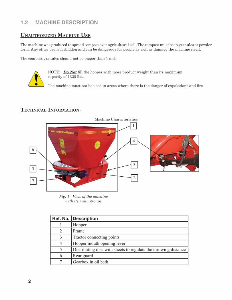
TECHNICAL INFORMATION -
Machine Characteristics
2
Ref. No. Description1 Hopper2 Frame3 Tractor connecting points4 Hopper mouth opening lever5 Distributing disc with sheets to regulate the throwing distance6 Rear guard7 Gearbox in oil bath
Fig. 1 - View of the machine with its main groups
1
4
3
2
6
5
7

2 SAFETYSAFETY ALERT SYMBOL
Why is SAFETY important to you?
The Safety Alert symbol identifi es important safety messages on the spreader and in the manual. When you see this symbol, be alert to the possibility of personal injury or death. Follow the instructions in the safety message.
This Safety Alert symbol means ATTENTION! BECOME ALERT! YOUR SAFETY IS INVOLVED!
Accidents Disable and Kill Accidents Cost Accidents Can Be Avoided
3 Big Reasons
DANGER - Indicates an imminently hazardous situation that, if not avoided, will result in death or serious injury. This signal
word is to be limited to the most extreme situations typically for machine components which, for functional purposes, cannot be guarded.
WARNING - Indicates a potentially hazardous situation that, if not avoided, could result in death or serious injury, and includes hazards that are exposed
when guards are removed. It may also be used to alert against unsafe
practices.
CAUTION - Indicates a potentially hazardous situation that, if not avoided, may result in minor or moderate injury. It may also be used to alert against unsafe practices.
SIGNAL WORDS:
Note the use of the signal words DANGER,WARNING and CAUTION with the safety messages. The appropriate signal word for each message has been selected using thefollowing guide-lines:
SI NO LEE INGLES, PIDA AYUDAA AIGUIEN QUE SI LO LEA PARAQUE LE TRADUZCA LASMIDIDAS DE SEGURIDAD.
If you have any questions not answered in this manual or require additional copies or the manual is damaged, please contact your dealer.
3

4
2.1 GENERAL SAFETY
YOU are responsible for the SAFE operation and maintenance of your spreader. YOU must ensure that you and anyone else who is going to operate, maintain or work around the spreader be familiar with the operating and maintenance procedures and related SAFETY information contained in this manual. This manual will take you step-by-step through your work-ing day and alerts you to all good safety practices that should be adhered to while operating the spreader.
Remember, YOU are the key to safety. Good safety practices not only protect you, but also the people around you. Make these practices a working part of your safety program. Be certain that EVERYONE operating this equipment is familiar with the recom-mended operating and maintenance procedures and follows all the safety precautions. Most accidents can be prevented. Do not risk injury or death by ignoring good safety practices.
• Spreader owners must give operating instructions to operators or employees before allowing them to operate the machine, and at least annually there after per OSHA (Occupational Safety and Health Administration) regulation 1928.57.
• The most important safety feature on this equipment is a SAFE operator. It is the operator's responsibility to read and understand ALL Safety and Operating instructions in the manual and to follow these. Most accidents can be avoided.
• A person who has not read and under- stood all operating and safety instructions is not qualifi ed to operate the machine. An untrained operator exposes himself and bystanders to possible serious injury or death.
• DO NOT modify the equipment in any way. Unauthorized modifi cation may im- pair the function and/or safety and could affect the life of the equipment.
• Think SAFETY! Work SAFELY!
1. Read and understand the Operator's Manual and all safety signs before operating, maintaining, or adjusting the spreader.
2. Have a fi rst-aid kit available for use should the need arise and know how to use it.
3. Have a fi re extinguisher available for use should the need arise and know how to use it.
4. Wear appropriate protective gear. This list includes but is not limited to:
- A hard hat - Protective shoes with slip resistant soles - Protective goggles, glasses or face shield - Heavy gloves - Protective clothing
5. DO NOT allow riders.
6. Wear suitable ear protection for prolonged exposure to ex- cessive noise.
7. Place all controls in neutral, stop tractor engine, set park brake, remove ignition key and wait for all moving parts to stop before servicing, adjusting, repairing, or unplugging.
8. Clear the area of people, especially small children, before starting.
9. Review safety related items annually with all personnel who will be operating or maintaining the spreader.

2.2 EQUIPMENT SAFETY GUIDELINES
5
Safety of the operator and bystanders is one of the main concerns in designing and developing a spreader. However, every year many accidents occur which could have been avoided by a few seconds of thought and a more careful approach to handling equipment. You, the operator, can avoid many accidents by observing the following precau-tions in this section. To avoid personal injury or death, study the following precautions and insist those working with you, or for you, follow them. If potentially dangerous situations are known, ac-cidents can be prevented!
• The compost spreader, as described in this instruction and maintenance booklet, has been specifi cally designed for the spreading of dry material. Any other use jeopardizes the operator's safety and the machine integrity.
• NEVER use alcoholic beverages or drugs which can hinder alertness or coordination while operating this equipment. Consult your doctor about operating this machine while taking prescription medications.
• Under no circumstances should young children be allowed to work with this equipment. Do not allow persons to operate or assemble this unit until they have read this manual and have devel-oped a thorough understanding of the safety precautions and of how it works. Review the safety instructions with all users annually.
• This equipment is dangerous to children and persons unfamiliar with its operation. The operator should be a responsible, properly trained and physically able person familiar with farm machinery and trained in this equipment's operations. If the elderly are assisting with farm work, their physical limitations need to be recognized and accom-modated.
• NEVER exceed the limits of a piece of ma-chinery. If its ability to do a job, or to do so safely, is in question - DON'T TRY IT.
• Do not modify the equipment in any way. Unauthorized modifi cation may impair the function and/or safety and could affect the life of the equipment.
Only operate this spreader on a properly sized and equipped tractor.
When using the compost spreader, it is particularly forbidden:
● The attachment to vehicles of unsuitable power or weight. ● To use other than 540 R.P.M. PTO speed. ● To use the machine without inserting the pins and cotter pins when supplied. ● To work on excessive slopes. ● To lift the machine when the power take off is engaged. ● To approach the machine when wearing inappropriate work clothing. ● To get on the machine while it is being used or transported.
Think SAFETY! Work SAFELY! If potentially dangerous situations are known, accidents can be prevented
DANGER - Operating this spreader in an application for which it is not
designed and/or operating with the wrong size tractor can cause spreader component damage and equipment failure resulting in possible serious injury or death.
OPERATOR'S REQUIREMENTS:
All operators using the equipment must be competent and meet necessarily the following features:
Physical - good eyesight, coordination and capability of carrying out all functions required for the machine's use.
Mental - Capability of understanding and applying the established rules and safety precautions. Users must pay attention and be sensible for their own and other people's safety.
Training - Users must have read and studied this manual, its eventual enclosed graphs and schemes and its identifi cation and danger plates. They must be skilled and trained on any use or maintenance activities.
2.3 SAFETY TRAINING
Safety is a primary concern in the design and manu-facture of our products. Unfortunately, our efforts to provide safe equipment can be wiped out by a single careless act of an operator or bystander.
In addition to the design and confi guration of equip-ment, hazard control and accident prevention are dependent upon the awareness, concern, prudence and proper training of personnel involved in the operation, transport, maintenance and storage of this equipment.
It has been said, "The best safety feature is an informed, careful operator." We ask you to be that kind of an operator. It is the operator's responsibility to read and understand ALL Safety and Operating instructions in the manual and to follow these. Accidents can be avoided.
Working with unfamiliar equipment can lead to careless injuries. Read this manual, and the manual for your tractor, before assembly or operating, to ac-quaint yourself with the machines. If this machine is used by any person other than yourself, or is loaned or rented, it is the machine owner's responsibility to make certain that the operator, prior to operating:
a. Reads and understands the operator's manuals.
b. Is instructed in safe and proper use.
Should ownership of the equipment be transferred, this manual must also be transferred.
Know your controls and how to stop tractor, engine and machine quickly in an emergency. Read this manual and the one provided with your tractor.
Train all new personnel and review instructions frequently with existing workers. Be certain only a properly trained and physically able person will operate the machinery. A person who has not read and understood all operating and safety instructions is not qualifi ed to operate the machine. An untrained operator exposes himself and bystanders to possible serious injury or death. If the elderly are assisting with farm work, their physical limitations need to be recognized and accommodated.
For any part of this manual that you do not under-stand, contact your dealer or Gearmore, Inc.
2.4 SAFETY SIGNS
1. Safety decals and this manual must be considered a permanent part of your equipment.
2. Keep safety signs clean and legible at all times.
3. Replace safety signs that are missing or have become illegible.
4. Replaced parts that displayed a safety sign should also display the current sign.
5. Safety signs are available from your authorized dealer or from Gearmore.
How To Install Safety Signs:
• Be sure that the installation area is clean and dry.
• Be sure temperature is above 50º F (10º C).
• Determine exact position before you remove the backing paper.
• Remove the smallest portion of the split backing paper.
• Align the sign over the specifi ed area and carefully press the small portion with the exposed sticky backing in place.
• Slowly peel back the remaining paper and carefully smooth the remaining portion of the sign in place.
• Small air pockets can be pierced with a pin and smoothed out using the piece of sign backing paper.
6

2.5 PREPARATION
7
1. Never operate the tractor and spreader until you have read and completely understand this manual, the Tractor Operator's Manual and each of the Safety Messages found on the safety signs on the tractor and spreader.
2. Personal protection equipment, including hard hat, safety glasses, safety shoes and gloves are recommended during assembly, installation, operation, adjustment, maintaining, repairing, removal or moving the implement. DO NOT allow long hair, loose fi tting clothing or jewelry to be around equipment.
3. PROLONGED EXPOSURE TO LOUD NOISE MAY CAUSE PERMANENT HEARING LOSS! Tractors with or without equipment attached can often be noisy enough to cause permanent, partial hearing loss. We recommend that you wear hearing protection on a full-time basis if the noise in the Operator's position exceeds 80db. Noise over 85db on a long- term basis can cause severe hearing loss. Noise over 90db adjacent to the Operator over a long-term basis may cause perma- nent, total hearing loss.
NOTE: Hearing loss from loud noise (from tractors, chain saws, radios, and other such sources close to the ear) is cumulative over a lifetime without hope of natural recovery.
4. Always consider the features of the area where work is taking place. When the equipment is running, it is forbidden to stand within the fi eld of action of the spreader.
5. Before and while working, do not drink alcohol, take drugs, or any other substances which may alter your capability of working with machine tools.
6. Do not use the equipment under unsafe conditions. For instance, it is forbidden to execute makeshift repair activities just to start working. Operate only in daylight or good artifi cial light.
7. Be sure to have suffi cient fuel, to prevent a forced stopping of the machine, maybe during a critical movement.
8. Ensure that all safety shielding and safety signs are properly installed and in good condition.
9. Never operate implement without all shields in place and in good operational condition.
10. The operator must be familiar with the spreader and tractor and all associated safety practices before operating the spreader and tractor.

2.6 OPERATIONAL SAFETY
8
WHEN WORKING OR DURING THE MAINTENANCE ACTIVITIES IT IS NECESSARY TO REMEMBER:
The use of this equipment is subject to certain hazards that cannot be protected against by the mechanical means or product design. All operators of this equip-ment must read and understand this entire manual, paying particular attention to safety and operating instructions, prior to using. If there is something in this manual you do not understand, ask your supervi-sor, or your dealer, to explain it to you.
Most accidents occur because of neglect or careless-ness. Keep all helpers and bystanders at least sev-eral hundred feet from an operating spreader. Only properly trained people should operate this machine. Operation must be stopped when anyone comes within several hundred feet.
The labels and stickers providing instructions and pointing out the dangers, must not be removed, hid-den, or made illegible.
Do not remove, except in case of maintenance, the shields, guards, and defl ectors equipped on the spreader. When it is necessary to remove them, stop engine, handle with care and reassemble them properly before restarting the engine and using the equipment.
All shields, guards, and defl ectors equipped on the spreader must be maintained in good operational condition.
It is forbidden to lubricate, clean and adjust the moving parts while they are running.
During maintenance or adjustment activities on the equipment it is forbidden to use hands for executing operations for which there are specifi c tools.
Do not use tools in bad condition or inappropriately, for instance pliers rather than wrenches.
When maintenance or repairs are completed check out that no tools, wiping rags, or other materials are left inside spaces or guides with moving parts.
While using the equipment, it is forbidden to make more than one person give directions and make sig-nals. The eventual directions and signals relating to the load handling must be given by one person only.
Do not unexpectedly call an operator while he is working if not necessary; it is forbidden as well to frighten or throw objects at the operator, even if just for fun.
Watch out for those who are present, especially the children! Do not let people get on the machine.
When not in use, stop the vehicle's engine, park it on fl at ground with parking brake engaged and the PTO disengaged. Never leave equipment unattended with the tractor running.
Do not clean, lubricate, repair or adjust with the en-gine running and the machine lifted.
Do not allow riders on the spreader or tractor at any time. There is no safe place for any riders. Do not operate unless all personnel, livestock, and pets are several hundred feet away.
Never use the machine on steep slopes which may jeopardize the equipment's stability.
The manufacturer declines all responsibility for a lack of compliance with these instructions.
3 SET-UP - ASSEMBLY
9
DANGER - Pay attention to the tractor's front wheels grip when the equipment is set up and lifted; if the wheels appear to be too lightened, ballast the tractor front tires or add front weights.
CAUTION - After executing the above-mentioned activities it is always good to check that all bolts and nuts of your spreader are tightened (refer to the torque specifi cations in this manual)
3.1 DRIVELINE ATTACHMENT
Before assembling the PTO shaft, it is very important to check out that its number of revolutions and direction of rotation match those of the tractor. Moreover, read the manufacturer instruction manuals of the driveline and the tractor carefully. Before starting work, check the presence of the safety guards on the PTO of the machine, of the shaft and of the tractor. Check in particular that the safety guards cover the driveline throughout its extension.
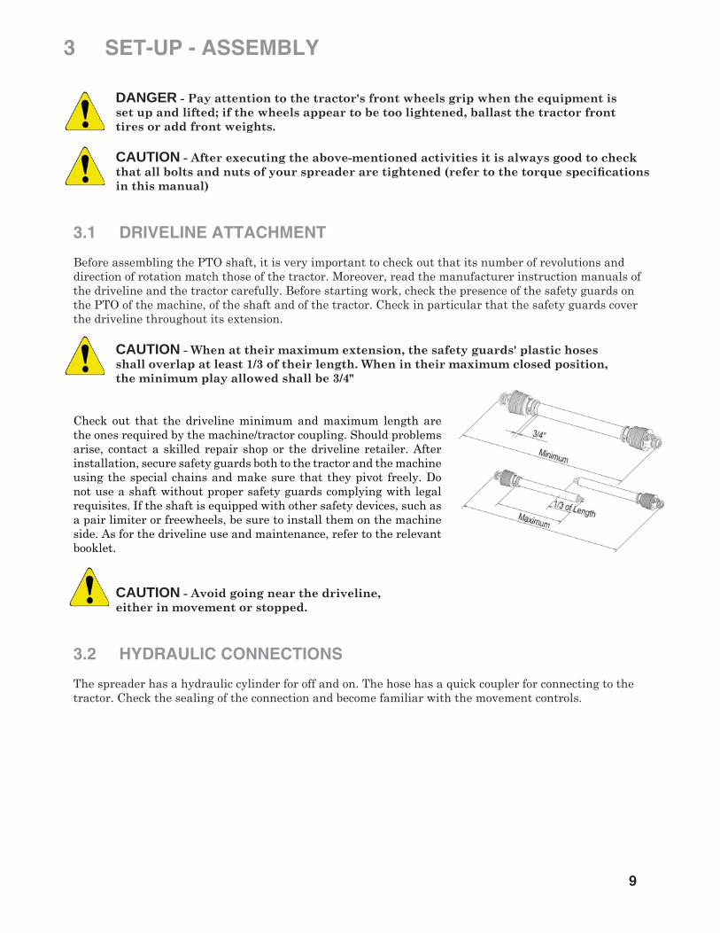
CAUTION - When at their maximum extension, the safety guards' plastic hoses shall overlap at least 1/3 of their length. When in their maximum closed position, the minimum play allowed shall be 3/4"
Check out that the driveline minimum and maximum length are the ones required by the machine/tractor coupling. Should problems arise, contact a skilled repair shop or the driveline retailer. After installation, secure safety guards both to the tractor and the machine using the special chains and make sure that they pivot freely. Do not use a shaft without proper safety guards complying with legal requisites. If the shaft is equipped with other safety devices, such as a pair limiter or freewheels, be sure to install them on the machine side. As for the driveline use and maintenance, refer to the relevant booklet.
CAUTION - Avoid going near the driveline, either in movement or stopped.
3.2 HYDRAULIC CONNECTIONS
The spreader has a hydraulic cylinder for off and on. The hose has a quick coupler for connecting to the tractor. Check the sealing of the connection and become familiar with the movement controls.
10
3.3 MACHINE USE
Before using the machine for the fi rst time, or after a long period of inactivity, carry out the following:
► Check that the machine is not damaged
► Check the mechanical parts, which must be in good condition and not rusted
► Check that there is not oil leakage coming from fi ttings
► Check that all safety guards are properly positioned
When these check-ups have been carried out, do not start the PTO with the spreader at work height but only after having lifted it up a few centimeters with the tractor lift. After this, it is possible to start engine, engage PTO, drop the machine down to work position and start using it. In the same way for operations involving change of direction, turning and going in reverse, lift the head a bit from the ground, after having disengaged the PTO, in order to avoid structure damage.
Before using the machine, one must be familiar with the controls and their work capabilities. Before starting work, make sure that no people or animals are within 100 feet. Keep the engine running at a rev speed that assures the machine the needed power for its use. Run a short way with the spreader working and check the quality of the work carried out. If it does not satisfy you, repeat and review the machine adjustment operations.
3.4 WORKING SPEED
The tractor speed during work depends on the area to be spread. However your speed should be between 4 to 6 MPH. The PTO speed must be within 540 RPM
3.5 MACHINE DISCONNECTION
When the machine is parked, one must:
~ Set the parking brake ~ Lower the machine resting feet ~ Place the spreader on the ground ~ Disengage the tractor PTO ~ Turn the tractor engine off and remove the ignition key from the control panel ~ Descend from the drive position ~ Detach the driveline and remove A-frame pins ~ Get back onto the tractor, start it up and move away carefully

11
4 OPERATION
When operating with the band spread side conveyor, close the shutter opening completely that is nearest the material exit. Open the opposite shutter about half way and then adjust to your requirements.
When operating the unit without the side spread conveyor, open both shutters approximately 1/4 open and then adjust to your requirements.
CAUTION - Never start spreading with both shutters fully open as you could overload the spinner and shear the safety roll pin.
The hydraulic cylinder is only used for on and off. The two hopper opening levers are used to adjust the amount of fl ow.
4.1 WORKING SPEED
The working speed depends on fi eld conditions, but maximum speed is 6 MPH. The power takeoff speed must be 540 RPM maximum.

12
4.2 ROAD TRANSPORT1. Comply with state and local laws governing highway safety and movement of farm machinery on public roads.
2. The use of fl ashing amber lights is acceptable in most localities. However, some localities pro- hibit their use. Local laws should be checked for all highway lighting and marking requirements.
3. At all times, when driving the tractor and equipment on the road or highway under 20 mph (32 kph) use fl ashing amber warning lights and a slow moving vehicle (SMV) identifi cation emblem. Do not exceed 20 mph (32 kph). Reduce speed on rough roads and surfaces.
4. Plan your route to avoid heavy traffi c.
5. Always install transport locks, pins, or brackets before transporting.
6. Do not drink and drive.
7. Be a safe and courteous driver. Always yield to oncoming traffi c in all situations, including narrow bridges, intersections, etc. Watch for traffi c when operating near or crossing roadways.
8. Turn into curves or go up or down hills only at a low speed and at a gradual steering angle. Make certain that at least 20% of the tractor's weight is on the front wheels to maintain safe steerage. Slow down on rough or uneven surfaces.
9. Use extreme care and maintain minimum ground when operating close to ditches or fences. Be careful when turning sharp corners.
10. Never allow riders on either tractor or spreader.
4.3 STORAGEIf your spreader will not be used for a long period of time, respect the following suggestions:
1. Wash the machine thoroughly and dry it.
2. Lubricate all bearings with enough grease to eliminate any cavities where water condensation may occur and cause damage. Refer to "Maintenance Section" for location of all grease fi ttings. Be sure the vent on top of the gearbox is open.
3. Coat all exposed surfaces inside the spreader with oil or grease to prevent rusting and pitting during storage.
4. Protect the whole machine with a tarpaulin and put it in a dry place away from activity.
PRE-SEASON CHECK:
1. Check the oil level in the gearbox and lubricate all bearings. See "Lubrication".
2. Check out all equipment and replace damaged or worn parts.
3. Tighten all bolts and nuts (See "Torque Specifi cations"). 4. Inspect for missing and/or broken parts. Replace as necessary.
5. Be sure that the safety guards are in place and secure.
6. Run the spreader at a low RPM checking to make sure that all driveline parts are moving freely.

13
GEARBOX -
Use 90 weight gear lubricant Shell Omala or equal. Drain gearbox at 50 hours to get rid of all possible microscopic debris because of the friction of the new gears. then drain and replace oil every 2000 hours.
DRIVESHAFT -
Grease both crosses and shear pin yokes every 8 hours. It is also necessary from time to time, to untelescope the driveshaft to clean and re-grease the shaft.
For correct hardware tightening on the spreader, we suggest the use of a suitable torque wrench and the applicable torque as listed in the table below.
5 MAINTENANCE & LUBRICATION
5.1 LUBRICATION
5.2 TORQUE SPECIFICATIONS
M-THREADED SCREW / BOLTSBolt Grade
Thread 8.8 10.9Nm lb / ft Nm lb / ft
M6 11 8.5 17 12M8 28 20 40 30M10 55 40 80 60M12 95 70 140 105M14 150 110 225 165M16 240 175 305 225M18 330 250 475 350

14
6 REPLACEMENT PARTS 6.1 FRAME & GEARCASE

15
REF. QTY. PART NO. DESCRIPTION 1 1 327000007B Frame 2 1 503000002A Painted Agitator 2 1 503000009A Stainless Steel Agitator 3 1 610800600B Painted Hopper 600 lt. 3 1 610801000B Painted Hopper 1000 lt. 3 1 610840600B Stainless Steel 600 lt. 3 1 610841000B Stainless Steel 1000 lt. 4 1 512000001C Spreading Set (mounted from s/n 2921) 5 8 411065005Z Plain Washer Galvanized Steel UNI 6592 d.8 6 4 411041008Z Hexagon Locknut 6S Galvanized UNI 7474 M8 7 4 411002049Z Screw TE Galvanized 8.8 UNI 5739 M8 x 25 8 2 411050005Z Hexagonal Insert Threaded Galvanized w/Plain Head M8 x 18 9 2 409000003 Implement Mounting Pin I - II Cat. 10 1 409000002 Implement Mounting Pin Top Links I - II Cat. 11 3 411076006Z Grip Clips Galvanized type R d.4 x 76 12 2 501000004 Adjustment Opening 13 6 411065005X Stainless Steel Plain Washer UNI 6592 d.8 14 4 411002048X Stainless Steel Screw Bolt TE UNI5739 M8 x 20 15 8 411065004X Stainless Steel Plain Washer UNI 6592 d.6 16 2 411041008X Stainless Steel Hexagonal Self-Locking Nut UNI7474 M8 17 4 411041006X Stainless Steel Hexagonal Self-Locking Nut UNI7474 M6 18 4 411002034X Stainless Steel Screw Bolt TE UNI5739 M6 x 20 19 1 527000012 Central Unit SCU With Support 20 1 231000039A Protection of Spreading Disc Coupling 21 1 231000048C Protection 22 1 231000049C Support Bracket of the Protection 23 1 231000055C Support Bracket of the Protection 24 1 610800001A Hydraulic Remote Control
6.1 FRAME & GEARCASE

16
6.2 HOPPER
REF. QTY. PART NO. DESCRIPTION 1 1 328000010B Painted Hopper SCU 1000 lt. 2 1 231000464B Lockup Blade of the Shutter Hopper 3 2 411066043X PlainWasher Stainless Steel UNI 6592 d.16 48 x 3 4 3 411020049X Screw TTQS Stainless Steel UNI 5731 M12 x 45 5 4 411065007Z Plain Washer Galvanized UNI 6592 d.12 6 1 411040012Z Stainless Steel Hex Nuts 6S UNI 5588 M12 7 2 411041012Z Galvanized Hex Locknuts 6S UNI 7474 M12 8 2 411050005Z Hex Threaded Bushing Galvanized M8 x 18 9 8 411065007Z Plain Washer Galvanized UNI 6592 d.12 10 4 411040012Z Galvanized Hexagon Nuts 6S UNI5588 M12 11 4 411002089Z Screw TE Galvanized 8.8 UNI 5739 M12 x 35 12 2 411065005Z Plain Washer Galvanized UNI6592 d.8 13 2 411002048Z Screw TE Galvanized 8.8 UNI5739 M8 x 20 14 1 328000009B Lockup Blade Right of the Hopper Shutter 15 1 328000008B Lockup Blade Left of the Hopper Shutter 16 1 328000006C Lockup Blade of the Hopper Shutter 17 1 411065005X Plain Washer Stainless Steel UNI 6592 d.8 18 1 411040008X Stainless Steel Hexagon UNI5588 M8 19 1 411020020X Screw TTQS Stainless Steel UNI 5731 M8 x 16

17
6.3 AGITATOR
REF. QTY. PART NO. DESCRIPTION 1 1 303000002 Agitator FE 2 1 234000003 Agitator Interchangeable Blade 3 1 334000001 Blade Interchangeable with Agitator Nib 4 8 411066016Z Galvanized Plain Large Washer UNI 6592 d.8 x 24 x 2 5 4 411041008Z Galvanized Hexagon Locknut 6S UNI 7474 M8 6 4 411002049Z Screw TE Galvanized 8.8 UNI5739 M8 x 25 7 4 411011086Z Screw TSPEI Galvanized 10.9 UNI 5933 M12 x 35 8 4 411065007Z Plain Washer Galvanized Steel UNI 6592 d.12 9 4 411041012Z Galvanized Hexagon Locknut 6S UNI 7474 M12 10 3 411065006Z Plain Washer Galvanized Steel UNI 6592 d.10 11 3 411002070Z Screw TE Galvanized 8.8 UNI 5739 M10 x 35 12 1 331000030 Protection Cone of the Agitator

18
6.4 SPREADING DISC
REF. QTY. PART NO. DESCRIPTION 1 3 231000082 Vane 2 3 231000083 Long Vane Used Also For SCU 3 16 411065005X Plain Washer Stainless Steel UNI 6592 d.8 4 12 411070005X External Notched Washer UNI 8842A d.8 5 12 411040008X Stainless Steel Hex Nuts UNI 5588 M8 6 12 411002047X Screw TE Stainless Steel UNI 5739 M8 x 16 7 1 411060238 Spring Pin UNI 6873-71 8 x 40 8 1 411060181 Spring Pin UNI 6873-71 5 x 40 9 8 411065006Z Plain Washer Galvanized UNI 6592 d.10 10 4 411002065Z Screw TE Galvanized 8.8 UNI 5737 M10 x 120 11 1 305000001 Disc Flange 12 1 231000081 Spreading Disc with 6 Vanes 13 1 423000006 Gear Case 14 4 411041010Z Galvanized Hexagon Locknut 6S UNI 7474 M10 15 1 415000005 Plug 16 4 411020020X Screw TTQS Stainless Steel UNI 5731 M8 x 16 17 4 411041008X Stainless Steel Hex Locknuts 6S UNI 7474 M8 18 1 411063115 Spline B 8 x 7 x 32 UNI 6607-70 19 1 442000010 Universal Joint (Mounted on s/n 2921) 20 1 411040010Z Galvanized Hexagonal Nut UNI 5588 M10 21 1 411002067Z Screw TE Galvanized 8.8 UNI 5739 M10 x 20

19
6.5 STEEL THREADED BAR
REF. QTY. PART NO. DESCRIPTION 1 1 411055006X Steel Threaded Bar M10 2 3 411040010X Stainless Steel Hex Stainless Steel UNI 5588 M10 3 2 411072001 Nylon Washer 10 x 30 x 5 4 2 411065006X Plain Washer Stainless Steel UNI 6592 d.10 5 1 441000001 Indicator Position 6 1 439000012 Knurled Handle
6.6 HYDRAULIC CYLINDER
REF. QTY. PART NO. DESCRIPTION 1 1 420000001 Hydraulic Cylinder Double Acting D=20/40 L=150 2 5 411065009Z Plain Washer Galvanized UNI 6592 d.16 3 3 411041016Z Galvanized Hex Locknut UNI 7474 M16 4 1 411002114Z Screw TE Galvanized 8.8 UNI 5737 M16 x 80 5 1 418000002 Kit Hydraulic Hoses Dal Cero 4 6 1 311000002 Galvanized Rod M16 (Mounted from s/n 2921) 7 2 411040016Z Galvanized Hexagon Nut UNI 5588 M16
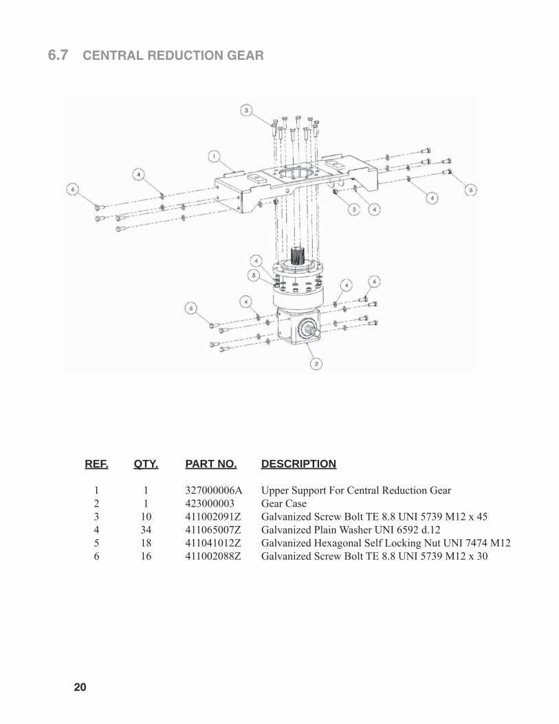
REF. QTY. PART NO. DESCRIPTION
1 1 327000006A Upper Support For Central Reduction Gear 2 1 423000003 Gear Case 3 10 411002091Z Galvanized Screw Bolt TE 8.8 UNI 5739 M12 x 45 4 34 411065007Z Galvanized Plain Washer UNI 6592 d.12 5 18 411041012Z Galvanized Hexagonal Self Locking Nut UNI 7474 M12 6 16 411002088Z Galvanized Screw Bolt TE 8.8 UNI 5739 M12 x 30
20
6.7 CENTRAL REDUCTION GEAR
6.8 STAINLESS STEEL CONVEYOR
21
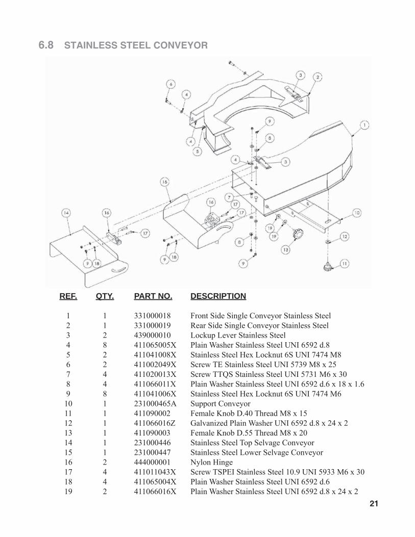
REF. QTY. PART NO. DESCRIPTION
1 1 331000018 Front Side Single Conveyor Stainless Steel 2 1 331000019 Rear Side Single Conveyor Stainless Steel 3 2 439000010 Lockup Lever Stainless Steel 4 8 411065005X Plain Washer Stainless Steel UNI 6592 d.8 5 2 411041008X Stainless Steel Hex Locknut 6S UNI 7474 M8 6 2 411002049X Screw TE Stainless Steel UNI 5739 M8 x 25 7 4 411020013X Screw TTQS Stainless Steel UNI 5731 M6 x 30 8 4 411066011X Plain Washer Stainless Steel UNI 6592 d.6 x 18 x 1.6 9 8 411041006X Stainless Steel Hex Locknut 6S UNI 7474 M6 10 1 231000465A Support Conveyor 11 1 411090002 Female Knob D.40 Thread M8 x 15 12 1 411066016Z Galvanized Plain Washer UNI 6592 d.8 x 24 x 2 13 1 411090003 Female Knob D.55 Thread M8 x 20 14 1 231000446 Stainless Steel Top Selvage Conveyor 15 1 231000447 Stainless Steel Lower Selvage Conveyor 16 2 444000001 Nylon Hinge 17 4 411011043X Screw TSPEI Stainless Steel 10.9 UNI 5933 M6 x 30 18 4 411065004X Plain Washer Stainless Steel UNI 6592 d.6 19 2 411066016X Plain Washer Stainless Steel UNI 6592 d.8 x 24 x 2

22
6.9 DRIVESHAFT

REF. QTY. PART NO. DESCRIPTION
1 1 0800403 Yoke With Pushbutton 1 3/8" Z6 2 2 08204 Cross Journal Assembly 04 (27 x 74.6) 5 1 08004021 Outer Tube Yoke B4 8 1 098700860 Spring Pin 8 x 60 12* 1 09881433100 CM. 100 Cardan Tube 03-04 - 43 x 3 M1 13* 1 09881364100 CM. 100 Cardan Tube 03-36 x 4.5 M1 16 1 098700855 Spring Pin 8 x 55 17 1 08004011 Inner Tube Yoke B4 21 1 086104P60A Torque Limiter LF1 Special 25 2 021904C001 Cone Shield Bell 03-04 26 1 025504C001 Outer Ring 03-04 27 1 025404C001 Outer Base Cone 03-04 28 6 0998052242 Screw 4.8 x 22 29 1 0988966B4108 Outer Safety Tube 30 1 0988961B4108 Inner Safety Tube 31 1 025404C002 Inner Base Cone 03-04 32 1 025504C002 Inner Ring 03-04 40 2 0252000001 Chain With Spring Catch 1-6 48 1 09872006 Label Danger Outer Drive Tube 49 1 09872010 External Shield Label 50 1 09872101 Instruction Booklet CE 51 1 0986014047 Complete Push Button 1 3/8" 14 x 47 71 8 09845236035 Spring D.6 72 1 086910104 Flange Yoke LF1X04 73 1 0981554125 Bushing 74 2 09833140 Friction Disc D.140 77 1 0869107P60 Hub With Flange LF1 P60 78 1 0986014075 Complete Push Button 1 3/8" 14 x 75 79 1 0869119 Inner Plate 80 1 0869112 Pressure Plate EST.LF1-LF3 81 8 099510085B Bolt M10 x 085 With Nut 93 1 B4108CE2 Outer Half Shaft Complete With Shields 94 1 B4108CE124301 Inner Half Shaft Complete With Shields 97 1 083CE04108 Complete Safety Guard LF1-LF3
* Part number is for 1 meter, tubing supplied in 3 meter bars
6.9 DRIVESHAFT
23

GEARMORE, INC., warrants each new Gearmore product to be free from defects in material and work-manship for a period of twelve (12) months from date of purchase to the original purchaser. This warranty shall not apply to implements or parts that have been subject to misuse, negligence, accident, or that have been altered in any way.
Our obligation shall be limited to repairing or replacement of any part, provided that such part is returned within thirty (30) days from date of failure to Gearmore through the dealer from whom the purchase was made, transportation charges prepaid.
This warranty shall not be interpreted to render us liable for injury or damages of any kind or nature, direct, consequential or contingent, to person or property. This warranty does not extend to loss of crops, loss because of delay in harvesting or any other expenses, for any other reasons.
Gearmore in no way warranties engines, tires, or other trade accessories, since these items are warranted separately by these respective manufacturers.
Gearmore reserves the right to make improvements in design or changes in specifi cation at any time, without incurring any obligations to owners or units previously sold.
Please be advised that all warranty work done by your dealer must be approved by Gearmore before work begins.
GEARMORE, INC.13477 Benson Ave.
Chino, CA 91710Always refer to and heed machine operating warning decals on machine.
7 LIMITED WARRANTY
24
The serial number of this product is stored in our computer database, thussubmitting a warranty registration card is not required.


