OPERATING AND PARTS MANUAL INDUSTRIAL ELECTRIC AIR COMPRESSORS MODELS 30DG, 40DG, AND 50DG WITH A TEFC MOTOR PALATEK, INC. dba SULLIVAN-PALATEK, MICHIGAN CITY, IN 46360 ALL RIGHTS RESERVED COPYRIGHT 2001 3/17/08 MFP Part Number: OPM3060-004
Transcript
OPERATING AND PARTS MANUAL
INDUSTRIAL ELECTRIC AIR COMPRESSORS
MODELS
30DG, 40DG, AND 50DG WITH A TEFC MOTOR
PALATEK, INC. dba SULLIVAN-PALATEK, MICHIGAN CITY, IN 46360 ALL RIGHTS RESERVED COPYRIGHT 2001
SCREW COMPRESSOR AIR-END EXCHANGE PROGRAM .............................................. 29
SECTION 7 - PARTS LISTING .............................................................................................. 307.1 PARTS ORDERING ................................................................................................. 307.2 RECOMMENDED SPARE PARTS .......................................................................... 307.3 MOTOR, COMPRESSOR AND MOUNTING PARTS - BASE MOUNTED ............... 327.4 LUBRICATION & COOLING SYSTEM ..................................................................... 347.5 INTAKE AND CAPACITY CONTROL SYSTEM ....................................................... 367.6 DISCHARGE SYSTEM ............................................................................................ 387.7 GAUGE PANEL & ELECTRICAL PARTS ................................................................ 407.8 DECAL & IDENTIFICATION .................................................................................... 41
1.1 GENERAL SULLIVAN-PALATEK designs all its compressors so they can be operated safely despite the fact that operating a motor driven air compressor is inherently hazardous. Responsibility for continued safe operation rests with those who install, use and maintain the equipment. The precautions offered in this section will minimize the inherent hazards and reduce the likelihood of accidental damage and injuries.
The operation of air compressors should be limited to personnel who have been so trained and specifically assigned to do so, and who have read and understand this operator’s manual. Failure to follow the instructions and safety precautions in this manual may increase the possibility of accidents or injuries. Never start this compressor unless it is safe to do so.Do not attempt to operate the air compressor with an unsafe condition relative to the compressor, the electrical system, the air piping, filtering, regulating, preparation, conditioning, valving, hosing or components. Open the main disconnect switch or circuit breaker, then lock it out and tag it to prevent anyone else from starting the compressor until the unsafe condition has been corrected. Operate compressors only in full compliance with all applicable Federal, State and Local codes and requirements such as OSHA, NEC, NFPA, CSA, etc. Do not modify this compressor without specific written approval from the factory.
1.2 PRESSURE RELEASE Open the pressure relief valve(s) periodically to be sure there is no blockage, obstruction, or inability to operate.
Shut machine off, open and lock-out disconnect switch and vent all pressure before opening or removing any filter element, line, tube, fitting, valve, plug, cover, connection or any other component on the air compressor or in the plant’s compressed air system. Remove oil filler cap only when compressor has been turned off, the disconnect switch locked open, and there is no pressure in the oil separation tank. Bleed off any residual pressure by opening the pressure relief valve. REMEMBER, compressors may re-start AUTOMATICALLY if not properly taken off the power line!
Do not use accessories such as tools, valves, filters, hoses, piping, dryers, etc. that are rated lower than the maximum pressure or temperature rating of this compressor. Do not exceed the accessory component manufacturers rated safe, continuous working pressure or temperature.
Install appropriate velocity-limiting valves (rated by pipe size and CFM) whenever air hose larger than ½ inch (102.5 mm) inside diameter is used anywhere in the system to reduce pressure in case of hose or connection failure. Install additional velocity limiting valves, in series, whenever 75 feet (22.8 m) of hose length is exceeded. These valves must comply with pertinent OSHA requirements.
Do not use air pressure greater than 30 PSI (207 kPa) for blow-off or cleaning purposes, and then only with effective chip guarding and personal protective equipment as may be required by OSHA.
Compressed air filters or lubricators with plastic bowls may be affected by the lubricant used.Steel bowls are recommended.
Keep personnel out of line with, and away from, the discharge opening of airlines, or tools, or other areas of direct, or deflected, compressed air discharge.
Do not allow anyone to engage in horseplay with air hoses as serious bodily injury or death may result.
Do not substitute bolts with material or markings different from original equipment.
Do not over-tighten any bolt, nut, fitting, connection, or spin-on filter element.
1.3 FIRES / EXPLOSIONS Clean up any spilled oil or oil leakage and repair oil leaks as soon as they are discovered.
Do not allow oil to accumulate on, in, or around acoustic noise material. Immediately replace any oil-soaked material after cleaning enclosure surface with nonflammable solvent.
Do not operate compressor when there is a possibility of its ingesting flammable, toxic or explosive fumes, mists or particulates.
Do not operate compressor with its temperature switch or any of three pressure switchesinoperative or incorrectly connected.
Keep conductive objects away from explosive live electrical parts such as terminals to avoid sparks that might serve as a source of ignition.
Replace the air/oil separator element only with factory original equipment replacement parts to be certain that anti-static provisions are present.
Ground the machine in accordance with National Electrical Code (NEC) requirements.
Do not use plastic pipe for compressed air.
1.4 MOVING PARTS Do not operate the compressor with its fan guard removed.
Keep clothing, hands, arms, and other parts of the body, away from the fan and drive coupling.
Wear snug-fitting protective clothing (no neckties) and confine long hair when working around compressor.
1.5 PHYSICAL DANGERS Wear OSHA approved personal protective gear including gloves, safety shoes, safety glasses, head covering and ear protection when working on or around the compressor.
Avoid bodily contact with hot oil, hot surfaces, sharp edges and corners. Keep all parts of the body away from all potential points of air discharge, including pressure relief valve ports.
Keep an adequate first-aid kit nearby. Obtain medical assistance promptly in case of injury. Do not ignore small cuts, burns or minor eye injuries as they may lead to infection.
Perform repairs and maintenance only in clean, dry conditions in a well-lighted and ventilated area.
Operate the compressor only in open or well-ventilated areas.
Monitor the point-of-use location for adequate ventilation.
1.6 TOXICITY Carefully analyze the compressor inlet conditions to be certain that no dangerous levels of contaminants are being ingested by the compressor. Do not use air from this compressor for breathing, as it may contain colorless, odorless yet lethal gases. Severe injury or death may result within a few seconds. Do not permit air from this compressor to contact foodstuff except in compliance with FDA Standard 21 CFM 178.3570 and all other applicable regulations. (Use food grade lubricant for such applications.)
1.7 ELECTRIC SHOCK Keep all parts of the body as well as any tools or other conductive objects away from exposed live parts of the electrical system. Maintain dry footing, stand on insulating surfaces and do not contact any other portion of the compressor when making adjustments.
Be certain that the equipment is properly grounded in accordance with NEC.
Initial installation and wiring must be done by a trained and qualified electrician and be in accordance with all Federal, State and Local codes, standards and regulations. Improper installation or unsafe servicing could result in serious bodily injury or death.
If a fuse should blow for any reason, replace it with a fuse of the same size, type and ampere rating. Doing otherwise may result in an unsafe condition.
1.8 LIFTING Lift or move the compressor only with equipment of sufficient load capacity which has been inspected and is in good condition.
Use extreme care when moving tank-mounted compressors because of the high center of gravity.
Firmly restrain the compressor to prevent tipping or rolling.
Keep personnel out from under and away from the area when lifting or moving the compressor.
Lift no higher than necessary. Carry as low as possible when moving.
Keep lifting operator in attendance whenever the compressor is suspended.
Set compressor down only on level surface capable of supporting several times the machine’s weight.
Do not lift entire machine by motor lifting eyes, as they are intended only for lifting the motor.
Drain condensate from Auxiliary Air Receiver prior to lifting.
1.9 AUTOMATIC START Do not assume that any air compressor is ready for maintenance, service, or trouble-shooting if it is not running. It may be in the “Automatic-Start” mode of its dual-control system and suddenly re-start, thereby creating a hazardous condition!
Close discharge air valves and shut machine off. Open main disconnect; lock it out and tag it to prevent others from inadvertently re-closing it.
1.10 NOISE Working near an open-air compressor (or an enclosed machine with doors and/or access panels open or removed), can prove hazardous even during short-term exposure. The noise may interfere with hearing verbal warnings or other sounds off impending dangers. For prolonged exposure to machinery noise, hearing protection is recommended and may be required by OSHA.
1.11 HAZARD WARNING SIGNS SULLIVAN-PALATEK compressors are all equipped with brightly colored, weather-resistant, pictorial/verbal self-adhesive decals. These are designed to warn the operator against potential hazards in order to minimize risk of property damage, bodily injury or death. All operators must be aware of the Warning Signs and follow the instructions thereon.
If any Warning Signs are missing, damaged or painted over, or located in such a position as to be unreadable in a given installation, new Warning Signs must be ordered. Be sure they are properly positioned and installed correctly. If any operators are not fully conversant with the English language and/or cannot comprehend the intended pictorial warnings, it becomes incumbent upon the owner, lessor or other responsible administrator to be sure the operator is properly trained and also made aware of, and understands, the meaning of all Warning Signs.
DECAL LOCATION
**WARNING SIGN** MOTOR STARTER HIGH VOLTAGE/MOVING PARTS MOTOR STARTER
**WARNING SIGN** INSTRUMENT PANEL COMPRESSED AIR INSTRUMENT PANEL
**WARNING SIGN** SEPARATOR TANK HOT OIL/PRESSURIZED AIR SEPARATOR TANK
SULLIVAN-PALATEK reserves the right to change the design or construction of the above compressors, or to offer them with options which will cause the subject equipment to differ from the above specifications, without reference to any descriptions in this manual.
SULLIVAN-PALATEK recommends using Palasyn 45, a synthetic lubricoolant for normal plant-air service. For compressors running two or three shift operations extended life lubricants such as Pallube 32p or AFX 32 are offered as factory fill. For extreme environments (i.e. fine particulate, caustic, acidic, or oxidant atmospheres) contact the factory for lubricant recommendations. Also for such conditions we would suggest oil analysis every 1,000 hours. Mixing of any other type of oil or synthetic fluid will void the 5-year compressor unit warranty and could result in greatly increased maintenance and service expenses.
2.2 APPLICATION GUIDE Ambient Temperature Range: +35 to +104° F (+1 to 40° C). The lower temperature limit is to prevent freeze-up of condensate in the aftercooler and/or control lines. When operating these compressors for plant air in food or beverage processing industries, contact the factory for a Lubricoolant that is FDA approved for “incidental contact with foodstuffs”. For instrument-grade air, contact the factory for recommendations related to specialized compressed air preparation accessories. Contact the factory for heat-recovery equipment, or any other specialized compressor-related accessories. Whenever a SULLIVAN-PALATEK rotary screw air compressor is installed in parallel with a reciprocating type compressor, it is imperative that the SULLIVAN-PALATEK be the “lead” machine and the reciprocating the “lag” machine. That is, the SULLIVAN-PALATEK machine should be the first to start and the last to stop when being operated in the “automatic stop/start” mode; or the first to load and the last to unload, when in the “continuous run” mode. This will result in extending the life of the reciprocating machine, with no adverse effect on the life of the rotary. It should also require the least electrical power consumption for the combination.
3.1 INTRODUCTION SULLIVAN-PALATEK Plant Air Compressors are electric motor driven, single-stage rotary screw type, continuous-duty compressors. The compressor’s design and construction offer the greatest value and lowest life-cycle cost of operation. The compressor package includes a direct connected electric motor driven compressor, air intake capacity control system air cooled cooling system, including a standard air cooled aftercooler, discharge system, instrument panel and electrical system. They are available base mounted or tank mounted with or without enclosures. These machines are intended for indoor installation, or protected outdoor operation in moderate climates.
For outdoor operation, contact your nearest SULLIVAN-PALATEK distributor or the factory for specific options.
3.2 COMPRESSOR UNIT SULLIVAN-PALATEK compressors feature direct connected, single stage, positive displacement, flood lubricated rotary screw air compressor units with heavy duty long life tapered roller bearings. The lubricoolant fluid is injected directly into the compressor unit and mixes with the air as it is compressed by the rotors. The lubricoolant lubricates the rotors, bearings and shaft seal; cools the compressor by absorbing much of the heat of compression and acts to block slippage of compressed air through the compressor’s internal clearances.
3.3 MOTOR The electric motor used to power each SULLIVAN-PALATEK G-Series 30 40 and 50 horsepower compressor is a standard three phase 60 Hertz AC induction type motor, fitted with a C-face register at the compressor drive end to assure proper coupling alignment at all times and double-extended to provide a simple, reliable fan drive without an additional fan motor, starter or wiring. The standard motor is connectable for 230 or 460 volts and satisfactory for use at 208 volts. (200/400 volt motors available on request) Contact the factory for any other requirements.
3.4 INTAKE/CONTROL SYSTEM The intake/control system consists of an air filter, connecting rubber sleeve, clamps, a combination compressor inlet valve/reverse-flow check valve, control signal regulator valve, solenoid control/blowdown valve, and a control pressure switch. (See Intake Control Schematic.) The air filter is a multi-stage dry-type with a high efficiency cleanable/replaceable element. The element should be cleaned periodically, depending upon the amount of particulates in the air, and replaced annually. This filter is adequate for areas of high air-borne dust concentrations and has a tubular intake to facilitate remote intake connection to cooler, cleaner air and/or for reduced noise level.
The intake valve controls the capacity or air delivery of the compressor in direct response to the plant air system demand via a varying signal from the control regulator valve. During periods of very low or zero air usage the inlet valve is held shut by an air signal from the solenoid control/blowdown valve. This air signal simultaneously reduces the pressure in the oil separation tank, allowing the compressor to run unloaded with minimum power consumption. Upon shutdown the intake valve checks shut to eliminate blowback.
Control operation - start mode: When the compressor is turned on, or starts automatically, the pressure will quickly rise to 60 psi (415 kPa), which is the setting of the minimum pressure valve. The control regulator and solenoid valve are both closed; therefore, the compressor inlet valve is wide open. The compressor is then drawing in its full rated capacity, but the air is held back by the minimum pressure valve. Upon reaching 60 psig the minimum pressure valve opens allowing the compressor to deliver its full rated capacity to the plant air piping system.
Modulating mode: Whenever less than the rated capacity of the compressor is being used, the service air pressure will continue to rise until the control regulator gradually opens. This applies pressure to the inlet valve piston, thus partially closing the inlet valve disc reducing the amount of air entering the compressor air inlet until it matches the amount of air being used. The control will function continually in this manner between the adjustable limits of 115 to 125 psi (750 to 860 kPa) in response to varying demands of the plant air system. The control regulator has an orifice in the controller piston, which vents a small amount of control air whenever it is sending a pressure signal to the intake controller capacity control. This orifice is vital to the smoothness of the control operation, and must not be restricted.
Unloaded/Shutdown modes: When little or no air is being used, the service line pressure will rise to the “cut-out” setting of the control pressure switch. This opens the control solenoid, which sends a pressure signal directly to the inlet valve piston. The inlet valve is held shut, while air is vented through an orifice fitting which reduces the pressure in the separation tank. With the selector switch in the “Run” position, the compressor runs unloaded until air demand increases. With the resumption of plant air usage, the line pressure signal is reduced to the “cut-in” setting of the control pressure switch where it closes. Then control air signal to the inlet valve will be dissipated allowing the inlet valve to reopen. The compressor returns to normal full load operation. Selecting the “Auto” position on the selector switch allows the motor to shut off whenever the “cut-out” pressure setting of the control pressure switch is reached. It remains in this “unloaded” mode for 10 minutes before shutting off. The compressor will restart whenever the line pressure drops to the “cut-in” pressure.
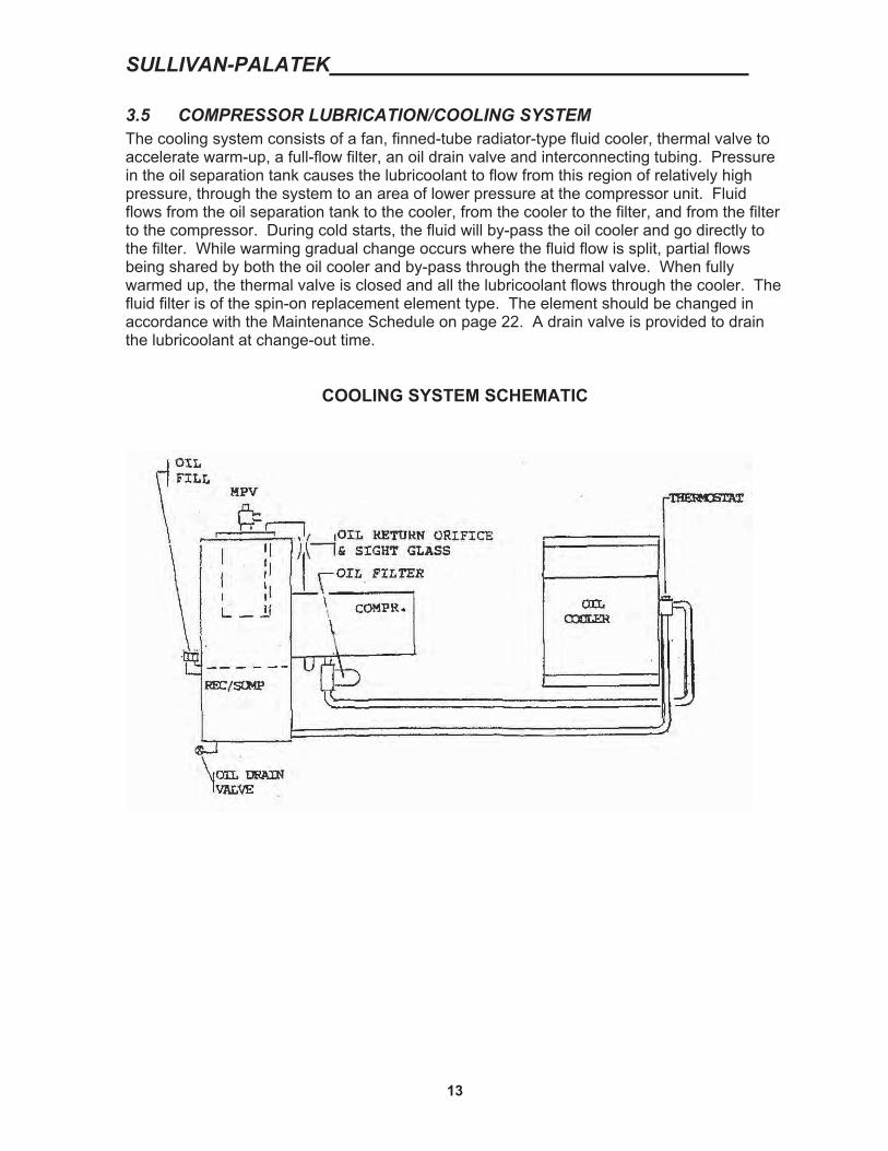
3.5 COMPRESSOR LUBRICATION/COOLING SYSTEM The cooling system consists of a fan, finned-tube radiator-type fluid cooler, thermal valve to accelerate warm-up, a full-flow filter, an oil drain valve and interconnecting tubing. Pressure in the oil separation tank causes the lubricoolant to flow from this region of relatively high pressure, through the system to an area of lower pressure at the compressor unit. Fluid flows from the oil separation tank to the cooler, from the cooler to the filter, and from the filter to the compressor. During cold starts, the fluid will by-pass the oil cooler and go directly to the filter. While warming gradual change occurs where the fluid flow is split, partial flows being shared by both the oil cooler and by-pass through the thermal valve. When fully warmed up, the thermal valve is closed and all the lubricoolant flows through the cooler. The fluid filter is of the spin-on replacement element type. The element should be changed in accordance with the Maintenance Schedule on page 22. A drain valve is provided to drain the lubricoolant at change-out time.
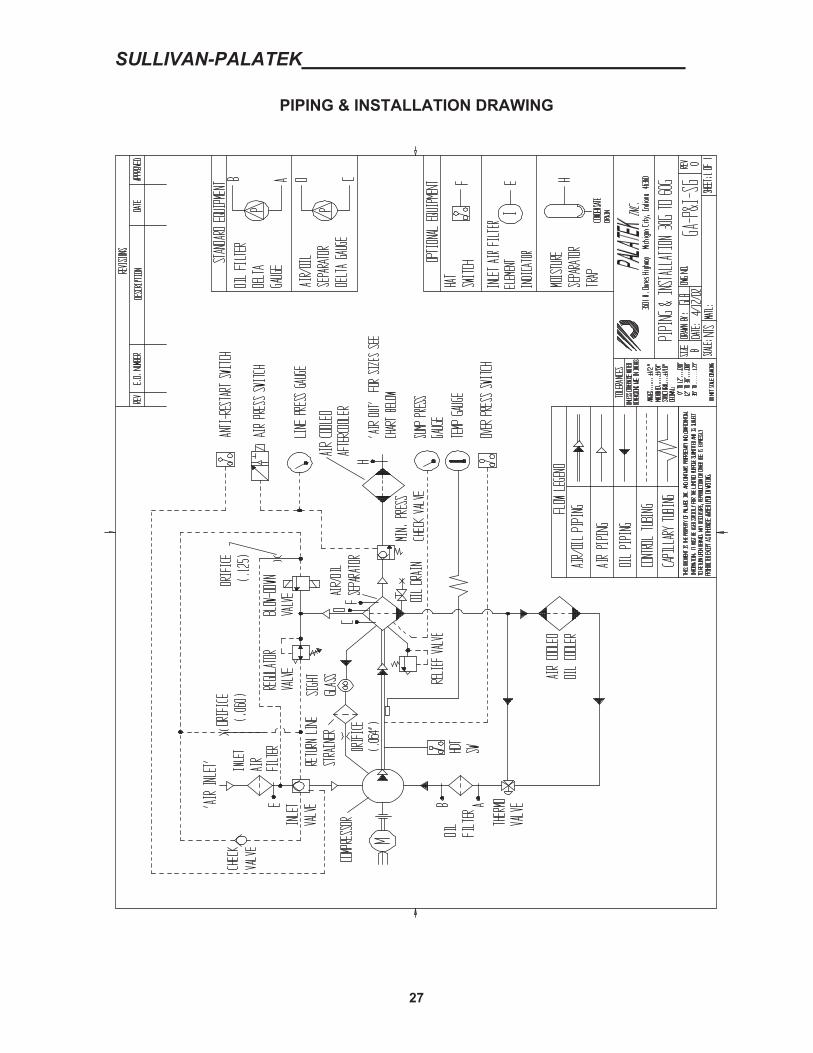
3.6 COMPRESSOR DISCHARGE SYSTEM The compressor unit discharges a mixture of compressed air and lubricoolant directly into the oil separation tank where it accomplishes the following three functions:
A) Primary Separation - by change of direction and reduction of velocity, which allow the heavier droplets of lubricoolant to fall.
B) Serves as the lubricoolant sump - by collecting the hot lubricoolant, prior to re-circulation through the cooling system.
C) Houses the final oil separation element - a replaceable, multi-layered, multi-media coalescing element with pleated initial stage for reduced velocity, improved separation performance and extended service life. Separated oil is returned to the compressor oil system via a small diameter return line, or scavenger tube.
A sight gauge is provided to monitor the lubricoolant level in the oil separation tank. A capped oil fill port is provided to keep the oil at the proper level and to refill the system after changing the lubricoolant.
WARNING: Do not remove caps, plugs or other components or connections while the compressor is running or pressurized. Shut compressor off, open and lock electrical disconnect, and relieve all sump pressure before doing so.
The oil separation tank is ASME rated for 200 psi (1379 kPa) maximum working pressure. A combination minimum- pressure/check valve in the separator cover assures a minimum pressure of 60 psig (415 kPa) for proper lubricoolant circulation and separation. It prevents reverse flow of compressed air from the auxiliary air receiver and/or the plant air system back through the compressor at shutdown or during periods of unloaded operation. A pressure relief valve (located upstream, or on the “wet” side of the separator) is set to open if a control malfunction would allow the pressure to exceed 150 psig (1035 kPa). (High-pressure units can be set to operate at control pressures from 175 to 190 psig.) However, since the opening of this valve is noisy and results in hot oil being expelled, a receiver over pressure switch has been installed to shut the motor off at 140 psig (190 psi on high pressure units.).
The panel-mounted pressure gauges show the pressure in the oil separation tank and line pressure. The compressor discharge temperature gauge is also panel-mounted for ease of record keeping and trouble-shooting. Normal discharge temperature should be approximately 180-220° F (82-105° C), or about 100° F (55° C above ambient). A C.D.T. switch is provided to shut the motor off if the compressor discharge temperature exceeds 240° F (115° C) in the event of gradual reduction in cooling system efficiency coupled with unattended operation. The reaction time of the switch is, however, not rapid enough to stop the compressor in the event of a sudden or complete loss of lubricoolant.
Additionally, differential pressure gauges showing the pressure drop across the oil filter and the separator element are supplied as an assist to proper maintenance of these elements.
3.7 STARTER AND ELECTRICAL PARTS The three-phase electric motor starter supplied with the SULLIVAN-PALATEK Plant Air Compressor has a NEMA-1 rated enclosure. This is also the location of: the control power transformer, the Run-On-Off-Reset, Auto Start selector switch, a control relay, the control pressure switch, the over-pressure shutdown switch and the anti-restart pressure switch.The starter contactor is amp-rated to match the motor power. That is 230 volts for the 30 hp machine and 460 volts for the 40 and 50 hp machines. Overloads must be selected and set to match the motor voltage/full load amp rating for each voltage application.
The selector switch allows the operator to select “Run” for continuous operation mode, where the motor runs continuously while the compressor loads and unloads, as required, to match air demand. This mode is generally used only if one wants to minimize motor starts.
The “Off-Reset” position is used to shut the compressor off and to reset the electrical control system following an automatic shutdown due to an over-temperature or over-pressure condition.
The “Auto-Start” position allows the compressor to shut down automatically whenever the auxiliary air receiver or plant air system pressure reaches the top (“Cut-out”) setting of the control air pressure switch. This relays a signal to the control relay, initiating a 10-minute timer, which then releases the motor starter pull-in coil stopping the motor. The motor will restart as soon as the plant air pressure drops to the “cut-in” setting on the pressure switch, provided that the oil separation tank pressure has been relieved via the blowdown valve.The compressor is prevented from starting under pressure by the anti-restart switch is in its normally closed mode. (This control mode saves power during periods of little or no air usage, and a timer is utilized to limit motor starts.)
The over-pressure shutdown switch acts to stop the compressor in the event of control malfunction or improper adjustment in order to prevent the pressure relief valve on the oil separation tank from suddenly opening.
The control power transformer converts power from one phase of the incoming motor power to a lower voltage for activation of control features. The primary (high voltage) incoming power and the secondary (control voltage) circuits are both provided with breakers to minimize the potential for damage due to overloading or short-circuit faults.
3.8 INSTRUMENTATION Each SULLIVAN-PALATEK Plant Air Compressor is equipped with two pressure gauges:one to monitor the sump tank pressure, another reading line pressure. There is a temperature gauge which senses compressor discharge temperature. In addition, there are two differential pressure gauges sensing the pressure drop across the oil filter and the separator element. It is recommended that the separator is changed when 5psid is reached, and the oil filter is changed when 15psid is reached. The compressor hour meter is located in the electrical box or on its door.
4.1 RECEIVING Carefully inspect for any signs of possible shipping damage.
4.2 WELDING Do not weld on compressor package.
4.3 LOCATION The compressor is designed for indoor operation or protected outdoor site with an ambient temperature range of 35 to 104° F (1 to 40° C). It is important that there be sufficient unobstructed ventilation airflow to prevent re-circulation of hot air. The compressor should be in a clean, dry and well-lighted area with ample space for maintenance and servicing.Duct the hot air outside if necessary to prevent excessively high ambient temperatures.Below is a listing of heat loads and fan air volumes that must be accommodated to keep machines operating normally. It is possible to utilize this heat for space heating, combustion air pre-heating, product drying, etc., - providing that no additional restriction is imposed upon the compressor cooling fan. Consult the factory for assistance if heat recovery is desired, or if other ambient temperatures are present.
MODEL 30DG 40DG 50DGAIR FLOW (CFM) 4600 5000 5300
HEAT REJECTION BTU/HR 81,408 109,392 137,376
Locate compressor as close as practical to where the compressed air is to be utilized. This saves piping and reduces power requirements necessary to transmit compressed air long distances.
4.4 SUPPORT The compressor may be mounted on any level surface capable of supporting its weight. It is recommended that the machine be mounted on isolation pads and secured to prevent movement.
4.5 ELECTRICAL CONNECTIONS Electrical wiring to the motor starter must be done by a qualified electrician in accordance with all pertinent Federal, State and Local codes concerning isolation switches, short circuit protection, grounding, etc.
Check all electrical connections for tightness!Check incoming voltage to be sure the motor is properly connected to match the starter and the overloads are properly set.
When power wiring has been installed, engage disconnect and “bump” compressor by turning to “Run” and then back to “Off.” Check for compressor proper rotation by: a.) Observing coupling rotation, b.) Observing pressure build up on sump gauge. If rotation is incorrect switch any two of the incoming lines after opening disconnect. Once re-energized the compressor should be ready to turn on.
4.6 MAINTENANCE INDICATION-DIFFERENTIAL INDICATION The compressor package has differential pressure gauges for change out indication for the separator element and fluid filter. Change differentials are indicated as follows: Separator element: 10 PSID, Fluid filter: 20 PSID, or once per year, whichever comes first.
4.7 DIRECTION OF ROTATION Once the control circuit has been checked, all piping installed, and the compressor lubricant level has been checked - reconnect the three motor leads by momentarily moving the selector switch to the “Run” position and then back to the “Off/Reset” position to check for correct compressor rotation. Rotation should be clockwise when viewed from the motor (i.e. looking in at compressor shaft)
Note: In all cases, the fan air should blow out, away from the motor.
4.8 COMPRESSED AIR PIPING Connect the compressor to the plant air system with a flexible connector rated for at least 200 psi (1400 kPa) and 275° F (135° C). Support the piping to insure that no pipe stress is transmitted to any compressor component. Piping should be as large as possible to provide extra air storage capacity and minimize transmission losses. Air dryers and filters may be required. Piping should be in a “closed loop” configuration, sloping to drain points, with service air outlets taken from the side, or preferably, the top of the pipe. Point-of-use filters, coalescers, regulators and/or lubricators are often required. (Note: never use plastic air piping or plastic bowls on filters or lubricators. See Section 1.) Inspect piping and air hoses frequently for leaks.
4.9 ADDITIONAL HELP By supplying the cleanest, coolest air available to the compressor inlet, maintenance and power consumption will be minimized. The heavy-duty air filter is locally mounted with provision for remote connection. Use a flexible connector at the filter inlet. (3” diameter.)Keep the piping as short and as straight as possible. Intake duct must be the same size as filter inlet, or larger, to accommodate long runs and several bends. Support intake ducting properly to prevent its weight being transmitted to the compressor air filter.
For multiple machine installation, contact the factory for special sequencing controls that can reduce power cost during part-load operation. Fan air ducted outside will reduce the machine noise somewhat, but care must be taken not to impose additional restriction to the fan airflow. With proper attention to the ducting, this fan air can also be utilized for heating purposes.
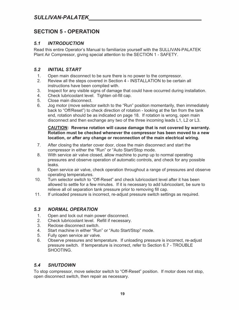
5.1 INTRODUCTION Read this entire Operator’s Manual to familiarize yourself with the SULLIVAN-PALATEK Plant Air Compressor, giving special attention to the SECTION 1 - SAFETY.
5.2 INITIAL START 1. Open main disconnect to be sure there is no power to the compressor. 2. Review all the steps covered in Section 4 - INSTALLATION to be certain all
instructions have been complied with. 3. Inspect for any visible signs of damage that could have occurred during installation. 4. Check lubricoolant level. Tighten oil-fill cap. 5. Close main disconnect. 6. Jog motor (move selector switch to the “Run” position momentarily, then immediately
back to “Off/Reset”) to check direction of rotation - looking at the fan from the tank end, rotation should be as indicated on page 18. If rotation is wrong, open main disconnect and then exchange any two of the three incoming leads L1, L2 or L3.
CAUTION: Reverse rotation will cause damage that is not covered by warranty. Rotation must be checked whenever the compressor has been moved to a new location, or after any change or reconnection of the main electrical wiring.
7. After closing the starter cover door, close the main disconnect and start the compressor in either the “Run” or “Auto Start/Stop mode.
8. With service air valve closed, allow machine to pump up to normal operating pressures and observe operation of automatic controls, and check for any possible leaks.
9. Open service air valve, check operation throughout a range of pressures and observe operating temperatures.
10. Turn selector switch to “Off-Reset” and check lubricoolant level after it has been allowed to settle for a few minutes. If it is necessary to add lubricoolant, be sure to relieve all oil separation tank pressure prior to removing fill cap.
11. If unloaded pressure is incorrect, re-adjust pressure switch settings as required.
5.3 NORMAL OPERATION 1. Open and lock out main power disconnect. 2. Check lubricoolant level. Refill if necessary. 3. Reclose disconnect switch. 4. Start machine in either “Run” or “Auto Start/Stop” mode. 5. Fully open service air valve. 6. Observe pressures and temperature. If unloading pressure is incorrect, re-adjust
pressure switch. If temperature is incorrect, refer to Section 6.7 - TROUBLE SHOOTING.
5.4 SHUTDOWN To stop compressor, move selector switch to “Off-Reset” position. If motor does not stop, open disconnect switch, then repair as necessary.
5.5 RESTARTS After a power failure, open and lock out the main disconnect, check all fuses and move selector switch to “Off-Reset” position. Close disconnect switch and follow Normal Operation start-up procedure.
Following a shutdown caused by either of the protective switches (i.e. cdt, or rop), open and lock out the main disconnect switch. Correct the cause of shutdown and reset electrical controls. Then close the disconnect and follow Normal Operation start-up procedure.
If the overload has tripped the motor off, first open and lock out the disconnect, then push the starter overload reset button and check to be sure it is set properly and correctly adjusted.NOTE: Never adjust the overload higher than indicated by starter manufacturer to match motor nameplate amperage rating; an unsafe operating condition will result!
Daily - 1. Check lubricoolant level prior to start-up. 2. Drain condensate from auxiliary receiver, if so equipped. 3. Observe the instrument panel gauges. 4. Keeping a daily log of all operating parameters is recommended.
First 50 hours-
Change compressor lubricoolant filter.
Every 1,000 hours - 1. Change compressor lubricoolant filter. 2. Take sample of lubricoolant and submit for analysis if operating in severe
environment. (Ex: chemical fumes, oxidizing elements, fine dust) 3. Inspect air filter element.
When using Palasyn 45: Every 4,000 hours or once a year, whichever occurs first - Drain lubricoolant and replace with a fresh charge. Inspect interior of tank. Clean tank if any build-up of deposits is present. This may have to be done sooner depending upon results of lubricoolant analysis. Replace air/oil separator element and the air filter element.
When using Pallube 32p: Every 8,000 hours - Change Pallube 32p lubricoolant and inspect tank interior. Replace air/oil separator element.Replace air and oil filter.
When using Pal Extra 44: Every 10,000 hours- Change AFX 32 and inspect tank interior. Replace air/oil separator, as well as air and oil filter element.
As Required - 1. Clean or replace air filter element (P/N 00521-060 for 30 and 00521-082 for 40 & 50
HP).2. Clean exterior surfaces of oil cooler/aftercooler. 3. Clean and grease MPV with a Lithium Grease ex: Lubriplate 630-2 or Mobil SHCPM. 4. Rebuild inlet valve every two years.
6.2 OIL FILTER **Replace element if differential pressure exceeds 15 psid or every 1,000 hours**
1. Open and lockout main disconnect. 2. Relieve all internal system pressure. 3. Using a strap wrench, remove spin-on oil filter element. (P/N 00520-017) 4. Spread a thin film of grease on the gasket. 5. Install element by hand until gasket touches the filter head. 6. Tighten 2/3 to one more turn. 7. Check for leaks after compressor is up to temperature.
6.3 AIR FILTER **Inspect every 1,000 hours or sooner in severe dust conditions**
1. Open and lock out main disconnect. 2. Remove end cover by operating snap-catch to release cover. 3. Remove air filter element, taking care to prevent dirt, which has collected on the outer
surface of the element from falling into the open compressor inlet. Wipe dust from inside of housing with a damp cloth. NOTE: To minimize downtime, it is recommended that a spare element be kept on hand. Check model and serial number for proper element number.
4. Replace element as needed. NOTE: An optional safety element is available. For fine dust conditions, a smaller micron element is also available.
5. Snap the end cover back on once the filter element has been replaced.
6.4 AIR/OIL SEPARATOR **Replace annually or if differential pressure exceeds 8 psid**
1. Open and lock out main disconnect. 2. Disconnect main air line to aftercooler. 3. Disconnect control air. Pick up line @ MVP. 4. Disconnect oil return scavenge line. 5. Unbolt cover in a diagonal criss-cross pattern. 6. Remove cover and separator element. 7. Drain lubricoolant and clean interior of oil separation tank if element appears dirty. 8. Clean flange and cover surfaces. (If rusty, clean thoroughly and paint with high
temperature paint. 9. Coat surfaces of gasket lightly with lithium grease.
10. Install new separator element. (Check to make sure the metal flange is grounded to the tank via the clips on the separator)
11. Replace cover. 12. Tighten all cover bolts progressively in a diagonal criss-cross pattern until all bolts
are properly torque to 50ft lbs for 3/8” bolts and125 ft-lbs for 1/2” bolts. These separator cover bolts are a special high-strength alloy, designated “SAE GRADE 8.”Only grade 8 bolts are allowed. No substitutions!
13. Reconnect all tubing.
6.5 BOLT TORQUE SPECS
TORQUE SPECIFICATIONS: GRADE 8 BOLTS 3/8” 50 ft. lb. GRADE 8 BOLTS 1/2” 125 ft. lb.
6.6 PRESSURE ADJUSTMENT Two capacity control features are incorporated in the Sullivan-Palatek compressors. The control pressure switch (CPS) will cycle the compressor between loaded and unloaded operation. This switch should be set so that the compressor loads when the line pressure falls to the lowest pressure required to operate plant equipment, and unloads the compressor at some higher pressure (normally about 10 psi above load pressure.) The other means of controlling compressor out-put is by means of the modulating or regulating valve. The modulating valve will proportionally pinch shut the inlet valve depending upon the existing line pressure.
To set the compressor controls, follow the following steps:
1. Turn in on modulating valve adjusting screw about one turn (this is to remove this control while setting the CPS).
2. Adjust the cut-out pressure by turning the top adjusting screw (CW to raise the pressure, CCW to lower).
3. Adjust the cut-in pressure by turning the lower adjusting screw. CW to decrease the cut-in; CCW to increase the cut-in pressure.
4. One the CPS has been set to the desired valves, the modulating valve must be reset. Loosen the adjusting screw until air is being vented from regulator at a pressure about 5 psi below the set cut-out pressure of the CPS. Lock adjusting screw in place.
Note that the selector switch on the electrical box has three settings; ‘Run’, “Off/Reset”, and ‘Auto’. In the ‘Auto’ position the compressor will shut off after running unloaded for 15 minutes. In the ‘Run’ mode the compressor motor is never shut off. For maximum efficiency of operation, if it is intended to operate the compressor in the ‘Auto’ mode, the pressure settings should have as large a differential as practical to allow the compressor to time out and shut off (consult factory for other optional energy saving options.)
SYMPTOM PROBABLE CAUSES AND REMEDY B. Machine shuts down with air demand
present.4. Discharge temperature switch open.
Monitor temperature gauge readings: normal operating pressure discharge temperature should be 160-220° F (100 F above ambient). Switch is set to trip at 235-245° Fa. Cooling airflow restricted. Clean
cooler and check for proper ventilation.
b. Ambient temperature is too high. Provide sufficient ventilation.
c. Low lubricoolant level. Add lubricoolant.
d. Clogged oil filter. Change the oil filter element.
e. Cooler thermostat not functioning properly. Replace thermostat.
f. Defective discharge temperature switch. Replace.
SYMPTOM PROBABLE CAUSES AND REMEDY C. Machine will not build up full discharge
pressure.1. Air demand is too great. Repair system
air leaks. Add compressor capacity to satisfy demand.
2. Dirty air filter. Clean or change element as required.
3. Control pressure regulator out of adjustment. Adjust regulator by loosening lock nut and turning screw in 1/2 to 1 turn.
4. Defective control regulator. Check diaphragm and replace if necessary.
5. Blowdown valve open. Repair or replace. 6. Faulty over pressure switch. Adjust or
replace.
SYMPTOM PROBABLE CAUSE AND REMEDY D. Line pressure rises above cut-out
pressure.1. Leak in control system tubing causing
loss of pressure signals. 2. Improperly adjusted or defective pressure
switch. Readjust or replace switch. 3. Defective solenoid valve. Readjust or
replace if necessary. 4. High pressure shutdown switch is
defective. Replace. 5. Faulty inlet valve. Repair or replace.
SCREW COMPRESSOR AIR-END EXCHANGE PROGRAM After the warranty period has expired a factory re-manufactured air-end can be purchased on an exchange basis. All bearings and seals have been replaced. All other parts not meeting our quality standards are also replaced. The air end is then factory tested prior to shipment. A re-manufactured air-end has a warranty which is 12 months from start up date or 18 months from date of shipment in accordance with the terms set forth in the new air-end warranty found on pages 42 & 43.
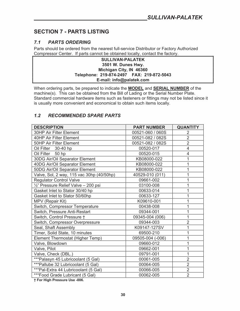
7.1 PARTS ORDERING Parts should be ordered from the nearest full-service Distributor or Factory Authorized Compressor Center. If parts cannot be obtained locally, contact the factory.
SULLIVAN-PALATEK3501 W. Dunes Hwy.
Michigan City, IN 46360 Telephone: 219-874-2497 FAX: 219-872-5043
When ordering parts, be prepared to indicate the MODEL and SERIAL NUMBER of the machine(s). This can be obtained from the Bill of Lading or the Serial Number Plate. Standard commercial hardware items such as fasteners or fittings may not be listed since it is usually more convenient and economical to obtain such items locally.
1.2 RECOMMENDED SPARE PARTS
DESCRIPTION PART NUMBER QUANTITY30HP Air Filter Element 00521-060 / 060S 2 40HP Air Filter Element 00521-082 / 082S 2 50HP Air Filter Element 00521-082 / 082S 2 Oil Filter 30-40 hp 00520-017 4Oil Filter 50 hp 00520-015 430DG Air/Oil Separator Element KB08000-022 140DG Air/Oil Separator Element KB08000-022 150DG Air/Oil Separator Element KB08000-022 1Valve, Sol, 2 way, 115 vac 30hp (40/50hp) 40529-010 (011) 1 Regulator Control Valve 09661-002 1½” Pressure Relief Valve – 200 psi 03100-008 1Gasket Inlet to Stator 30/40 hp 00633-014 1Gasket Inlet to Slator 50/60hp 00633-127 1MPV (Repair Kit) K09610-001 1Switch, Compressor Temperature 00438-008 1Switch, Pressure Anti-Restart 09344-001 1Switch, Control Pressure † 09345-004 (006) 1 Switch, Compressor Overpressure 09344-003 2Seal, Shaft Assembly K09147-127SV 1Timer, Solid State, 10 minutes 69500-210 1Element Thermostat (Higher Temp) 09505-004 (-006) 1 Valve, Blowdown 09660-012 1Valve, Pilot 09662-001 1Valve, Check (DBL.) 09791-001 1***Palasyn 45 Lubricoolant (5 Gal) 00061-005 2***Pallube 32 Lubricoolant (5 Gal) 00064-005 2***Pal-Extra 44 Lubricoolant (5 Gal) 00066-005 2***Food Grade Lubricant (5 Gal) 00062-005 2† For High Pressure Use -006.
7.3 MOTOR, COMPRESSOR AND MOUNTING PARTS - BASE MOUNTED
ITEM DESCRIPTION QTY MODEL30DG
MODEL40DG
MODEL50DG
1 AIR END 1 80108-230 80108-279 80127-231
1A SHAFT SEAL KIT 1 K09147-363
A SLEEVE, WEAR 1 00371-200
B SPACER, WEAR SLEEVE 1 00419-200
C GASKET, SHAFT SEAL 1 00633-032
D RING, RETAINING 1 01246-250
E SEAL, SHAFT 1 09148-200
2 BASE 1 10144-060 10144-060 10144-060
3 COUPLING GUARD 1 00697-016 00697-016 00697-017
4 MOTOR SUPPORT 1 18339-001 18339-023 18339-043
ISOLATOR 3 N/A N/A 08182-009
5 COUPLING 1 18516-060 18516-060 18516-060
5A COUPLING ELEMENT 1 08516-079 08516-079 08516-079
6 MOTOR 230/460 1 08747-430 08747-044 08747-054
7 AIR END SUPPORT 1 08339-021 18739-045 18339-044
FOR UNITS SOLD BEFORE 5/11/07 CALL SULLIVAN-PALATEKSERVICE FOR SHAFT SEAL KIT PART NUMBER. PLEASE HAVE AIR END S/N AND MACHINE S/N READY WHEN YOU CALL.
7 TUBE - SUMP TO THERMOSTAT 1 09610-017 09600-322 09600-329
8 TUBE CONN.: 5/8 X .875M (a) TUBE CONN.; 3/4 X 1.06M (b) 2 80120-010 (a) 80120-012 (b) 80120-012 (b)
10 TUBE - THERMOSTAT TO FILTER** 1 09610-018 09600-324 09600-328
11 TUBE ELBOW: 5/8 X 1/2 (a) TUBE ELBOW: 3/4 X 3/4 (b) 1 96391-108 (a) 96390-012 (b) 96390-012 (b)
12 OIL FILTER HEAD 1 08415-007 08415-007 08415-016*
14 OIL FILTER ELEMENT 1 00520-017 00520-017 00520-015*
19 FAN SPACER 1 N/A N/A N/A
20 FAN HUB 1 00851-002 00851-003 00851-003
21 FAN KEY 1 00858-001 00858-001 90947-126
22 SHROUD 1 13400-105 03400-018 03400-018
23 FAN GUARD 1 03216-105 03216-005 03216-005
N/A NOT APPLICABLE *Prior to 10/01/04 Oil Filter Head was 08415-007 Oil Filter Element was 00520-017 Lower temp stat 165 ºF 09505-004. ** After 10/1/04 the line went to tube P/N 09612-067 due to larger oil filter head. Water Cooled Machines:
30 hp Model 40 hp ModelOil Cooler #00549-001 Oil Cooler #00549-003 After Cooler #00549-001 After Cooler #00549-002 Water Reg. Valve #18338-008 Water Reg. Valve #18338-012
50 hp Model Oil Cooler #00549-003 After Cooler #00549-005 Water Reg. Valve #18338-012
1 Recommend Rebuilding Inlet Valve with K09790-007 Kit for 30DG-40G every 2 years. Recommend Rebuilding Inlet Valve with K09790-009 Kit for 50DG every 2 years.
New Industrial Compressors - 15 and greater Horsepower
Sullivan-Palatek warrants its new stationary industrial air compressor products to be free from defects in material and workmanship and against loss of capacity due to wear, subject to the following provisions:
Warranty Registration: The purchaser shall complete and return the warranty registration form within 10 days of start-up to validate the warranty. Failure to submit the warranty registration will cause the warranty effective date to be the Sullivan-Palatek ship date.
Warranty Period: The warranty period for applicable Sullivan-Palatek products is as follows (subject to the Exclusions and Limitations noted below):
� Total Package: 12 months (1 year) from the date of start-up by authorized distributor or 18 months from date of shipment by Sullivan-Palatek, whichever expires first.
� Compressor unit and Coupling Assembly: 24 months (2 years) from the date of start-up by authorized distributor or 30 months from date of shipment by Sullivan-Palatek, whichever expires first.
� Compressor Motor: 24 months (2 years) from the date of shipment by Sullivan-Palatek. � Compressor Shaft Seal: Warranted for 12 months (1 year) from date of start-up or 18 months from date of shipment by
Sullivan-Palatek, whichever expires first. � Components not manufactured by Sullivan-Palatek: Sullivan-Palatek’s warranty obligation with regard to equipment and
components not of its own manufacture is limited to the warranty actually extended to the company by its supplier. � Oil Leaks: Oil leaks will be covered under warranty for a period of 60 days from start up, but not longer than 90 days after
shipment from Sullivan-Palatek. These are defined as an escape of air or oil that only requires tightening to stop the leak. Other leaks are considered a failure of sealant or application thereof, or a part or assembly error and are covered for one year due to defects in workmanship, or to the limit of the manufacturer’s warranty.
Warranty replacement parts: Remainder of the original warranty period for the replaced part.
Sullivan-Palatek’s Obligations: Sullivan-Palatek’s exclusive obligations with respect to breach of warranty are (i) to repair or replace (at Sullivan-Palatek option and subject to return of defective parts) any defective part, (ii) to pay the reasonable cost of making the repair, or installing the replacement part, except the motor after the first year, (iii) to pay ground freight for the return of defective parts and shipment of replacement parts.
Customer Responsibility: As a condition to Sullivan-Palatek’s obligations under this warranty, customer shall; (i) give Sullivan-Palatek written notice of warrantable failure of the Sullivan-Palatek product within the applicable warranty period, (ii) make the product available for repair; (iii) return defective parts to Sullivan-Palatek; (iv) pay reasonable travel expenses for field repairs performed at customer’s request, (v) pay the costs of investigating performance complaints that are not covered by this warranty; and (vi) pay costs of air freight or other expedited delivery made at customer’s request.
Exclusions and Limitations: Disassembly of the air compressor unit will void this warranty and the unit exchange policy. Sullivan-Palatek has no obligation for product failures or defects resulting from overload, misuse, neglect, accident, failure to comply with Sullivan-Palatek’s product manual or failure to install product improvements provided by Sullivan-Palatek Attachment of accessories or service parts not supplied or recommended by Sullivan-Palatek may void the warranty of the product.
THIS WARRANTY IS SULLIVAN-PALATEK’S ONLY WARRANTY OF ITS STATIONARY INDUSTRIAL AIR COMRESSOR PRODUCTS AND IS IN LIEU OF ANY OTHER WARRANTIES, EXPRESS OR IMPLIED. ANY IMPLIED WARRANTIES OF MERCHANTABILITY, STATUTORY OR OF FITNESS FOR A PARTICULAR PURPOSE ARE EXCLUDED. SULLIVAN-PALATEK HAS NO OBLIGATION UNDER THIS WARRANTY OR OTHERWISE (REGARDLESS OF THE FORM OF ACTION) FOR SPECIAL, INDIRECT, CONSEQUENTIAL OR INCIDENTAL DAMAGES OF ANY CHARTER, INCLUDING WITHOUT LIMITATION, LOSS OF USE OF PRODUCTIVE FACILITIES OR EQUIPMENT LOST PROFITS, LOST INCOME, PROPERTY DAMAGE, EXPENSES INCURRED IN RELIANCE ON THE PERFORMANCE OF SULLIVAN PALATEK WHETHER SUFFERED BY THE BUYER OR ANY THIRD PARTY. THE TOTAL RESPONSIBILITY OF SULLIVAN PALATEK FOR CLAIMS, LOSSES, LIABILITIES OR DAMAGES, WHETHER IN CONTRACT OR TORT ARISING OUT OF OR RELATED TO ITS PRODUCTS SHALL NOT EXCEED THE PURCHASE PRICE.This warranty applies to all Sullivan-Palatek stationary industrial air compressors of 15 horsepower or greater shipped after January 1, 2008 superseding previous warranty policies, except to the extent expressly superseded by a later warranty. In the event of any conflict between this warranty and earlier warranty statements, the terms of this warranty will control.
New Industrial Compressors - 15 and greater Horsepower
Sullivan-Palatek warrants its new stationary industrial air compressor products to be free from defects in material and workmanship and against loss of capacity due to wear, subject to the following provisions:
Warranty Registration/Activation: The purchaser shall complete and return the platinum warranty registration/ startup card supplied with the machine within 10 days of start-up to validate the warranty. All information required on the cards must be filled out along with the customer’s signature and date in order to activate.
� Service must be maintained as stated in the operator’s manual and properly logged. A maintenance log shall be available at www.palatek.com and it is required to be updated after each service. (Distributor is responsible for maintaining the records and keeping the service log required. Copies of Invoices for service work and the log are required at time of warranty request)
� Use genuine Sullivan Palatek parts and fluids
Warranty Period: The warranty period for applicable Sullivan-Palatek products is as follows (subject to the Exclusions and Limitations noted below):
� Total Package: 12 months (1 year) from the date of start-up by authorized distributor or 18 months from date of shipment by Sullivan-Palatek, whichever expires first.
� Compressor Unit, Air/Oil Cooler, Sump Tank, and Coupling Assembly (halves): 60 months (5 years) from the date of start-up by authorized distributor or 62 months from date of shipment by Sullivan-Palatek, whichever expires first.
� Compressor Motor: 60 months (5 years) from the date of shipment by Sullivan-Palatek. � Compressor Shaft Seal and Coupling Element: Warranted for 12 months (1 year) from date of start-up or 18 months from
date of shipment by Sullivan-Palatek, whichever expires first. � Components not manufactured by Sullivan-Palatek: Sullivan-Palatek’s warranty obligation with regard to equipment and
components not of its own manufacture is limited to the warranty actually extended to the company by its supplier. � Oil Leaks: Oil leaks will be covered under warranty for a period of 60 days from start up, but not longer than 90 days after
shipment from Sullivan-Palatek. These are defined as an escape of air or oil that only requires tightening to stop the leak. Other leaks are considered a failure of sealant or application thereof, or a part or assembly error and are covered for one year due to defects in workmanship, or to the limit of the manufacturer’s warranty.
Warranty replacement parts: Remainder of the original warranty period for the replaced part.
Sullivan-Palatek’s Obligations: Sullivan-Palatek’s exclusive obligations with respect to breach of warranty are (i) to repair or replace (at Sullivan-Palatek option and subject to return of defective parts) any defective part, (ii) to pay the reasonable cost of making the repair, or installing the replacement part, except the motor after the first year, (iii) to pay ground freight for the return of defective parts and shipment of replacement parts.
Customer Responsibility: As a condition to Sullivan-Palatek’s obligations under this warranty, customer shall; (i) give Sullivan-Palatek written notice of warrantable failure of the Sullivan-Palatek product within the applicable warranty period, (ii) make the product available for repair; (iii) return defective parts to Sullivan-Palatek; (iv) pay reasonable travel expenses for field repairs performed at customer’s request, (v) pay the costs of investigating performance complaints that are not covered by this warranty; and (vi) pay costs of air freight or other expedited delivery made at customer’s request.
Exclusions and Limitations: Disassembly of the air compressor unit will void this warranty and the unit exchange policy. Sullivan-Palatek has no obligation for product failures or defects resulting from overload, misuse, neglect, accident, failure to comply with Sullivan-Palatek’s product manual or failure to install product improvements provided by Sullivan-Palatek Attachment of accessories or service parts not supplied or recommended by Sullivan-Palatek may void the warranty of the product.
THIS WARRANTY IS SULLIVAN-PALATEK’S ONLY WARRANTY OF ITS STATIONARY INDUSTRIAL AIR COMRESSOR PRODUCTS AND IS IN LIEU OF ANY OTHER WARRANTIES, EXPRESS OR IMPLIED. ANY IMPLIED WARRANTIES OF MERCHANTABILITY, STATUTORY OR OF FITNESS FOR A PARTICULAR PURPOSE ARE EXCLUDED. SULLIVAN-PALATEK HAS NO OBLIGATION UNDER THIS WARRANTY OR OTHERWISE (REGARDLESS OF THE FORM OF ACTION) FOR SPECIAL, INDIRECT, CONSEQUENTIAL OR INCIDENTAL DAMAGES OF ANY CHARTER, INCLUDING WITHOUT LIMITATION, LOSS OF USE OF PRODUCTIVE FACILITIES OR EQUIPMENT LOST PROFITS, LOST INCOME, PROPERTY DAMAGE, EXPENSES INCURRED IN RELIANCE ON THE PERFORMANCE OF SULLIVAN PALATEK WHETHER SUFFERED BY THE BUYER OR ANY THIRD PARTY. THE TOTAL RESPONSIBILITY OF SULLIVAN PALATEK FOR CLAIMS, LOSSES, LIABILITIES OR DAMAGES, WHETHER IN CONTRACT OR TORT ARISING OUT OF OR RELATED TO ITS PRODUCTS SHALL NOT EXCEED THE PURCHASE PRICE.
This warranty applies to all Sullivan-Palatek Platinum stationary industrial air compressors of 15D horsepower or greater shipped after January 1, 2008 superseding previous warranty policies, except to the extent expressly superseded by a later warranty. In the event of any conflict between this warranty and earlier warranty statements, the terms of this warranty will control.
S/N: SERVICE DIST: FILL OUT FOR EACH SERVICE OR REPAIR. MORE THAN ONE LINE MAY BE USED PER EACH SERVICE OR REPAIR. THIS FORM MAY BE PHOTOCOPIED AS NEEDED.