COMPRESSION AND AFFINE TRANSFORMS RESILIENT WATERMARKING Fahri Asvaroğlu Submitted to the Institute of Graduate Studies and Research in partial fulfillment of the requirements for the Degree of Master of Science in Electrical and Electronic Engineering Eastern Mediterranean University February 2006, Gazimağusa
Transcript
COMPRESSION AND AFFINE TRANSFORMS RESILIENT
WATERMARKING
Fahri Asvaroğlu
Submitted to the Institute of Graduate Studies and Research
in partial fulfillment of the requirements for the Degree of
Master of Science in
Electrical and Electronic Engineering
Eastern Mediterranean University February 2006, Gazimağusa
ii
Approval of the Institute of Graduate studies and Research ____________________________________ Prof. Dr. Ufuk Taneri Director I certify that this thesis satisfies the requirements as a thesis for the degree of Master of Science in Electrical and Electronic Engineering. _____________________________________ Prof. Dr. Derviş Z. Deniz
Chair, Department of Electrical and Electronic Engineering
We certify that we have read this thesis and that in our opinion it is fully adequate in scope and quality as a thesis for the degree of Master of Science in Electrical and Electronic Engineering. _______________________________________ Asst. Prof. Dr. Erhan A. İnce Supervisor Examining Committee 1. Asst. Prof. Dr. Erhan A. İnce ______________________________
2. Assoc. Prof. Dr. Hüseyin Özkaramanlı ______________________________
3. Asst. Prof. Dr. Hasan Demirel ______________________________
iii
ABSTRACT
Compression and General Affine Transformations Resilient Watermarking
Copy protection and intellectual rights management are pressing concerns of the
content owners who distribute content in the new digital world. Digital watermarking
technology is perceived as an enabling agent that allows more widespread sharing
and utilization of content while lessening the piracy worries. Many of the techniques
for embedding marks in digital images have been inspired by methods of image
coding and compression. Some of these include using the Discrete Cosine Transform
(DCT), Wavelets, Linear Predictive Coding, and Fractals. It has been demonstrated
that these methods perform well against compression however they lack robustness
to geometric transformations (attacks). Consequently, methods have emerged which
exploit the properties of the discrete Fourier transform (DFT) to achieve robustness
against rotation and scaling. The DFT methods can be divided into two categories.
Those based on invariance and those that embeds a template into the image which is
searched for during the detection of the watermark and yields the transformation
undergone by the image. Both of these methods exploit the properties of log-polar-
maps (LPM) and can only be used to detect changes of rotation and scale. Similarly
the log-log-map (LLM), allows the detection of aspect ratio changes however is still
unable to recover general transformations. In this work we combine two state of the
art techniques to develop a hybrid watermarking technique, which is both
compression and general affine transformation resilient. The watermark bits are
embedded in the DC components since the DC components have much larger
iv
perceptual capacity than any AC component. An adaptive watermarking algorithm
making use of the feature of texture masking of HVS is adopted. For recovering a
watermark from an image, which has undergone a general affine transformation, the
method proposed by Pereira is adopted. Unlike algorithms, which use log-polar or
log-log-maps, Pereira’s method concentrates on searching the space of possible
transformations. Since an exhaustive search is not possible careful pruning of the
search space is necessary. Simulation results indicate that the hybrid method would
be more advantageous in comparison to any stand-alone technique. Besides being
resilient against scaling and rotation the hybrid method is also resilient to general
affine transformations such as shearing, aspect ratio changes.
Keywords: DC coefficient watermarking, general affine transform matrix, Peak
signal to noise ratio, Template matching.
v
ÖZET
Sıkıştırma ve Genel İlgin Dönüşümlere Dirençli
Damgalama Yeni sayısal dünyamızda içeriği dağıtan mal sahiplerinin en büyük endişelerinden
ikisi kopyalamaya karşı koruma ve enetellektüel hak ve yetkilerinin korunması
konusudur. Sayısal damgalama teknolojisi bilginin daha geniş paylaşımına ve
kullanımına imkan kılarken ayni zamanda da korsanlıkla ilgili kaygıları azaltan bir
unsur olarak görülmektedir. Sayısal imgeler içine gizli damga yerleştirme
yöntemlerinden birçoğu imge kodlama ve sıkıştırma yöntemlerinden
esinlenmektedir. Bunların bazıları ayrık kosinüs dönüşümü (AKD), Dalgacıklar,
Doğrusal öngörücü kodlama, ve Fraktalları kullanmaktadır. Bu yöntemlerin
sıkıştırmaya karşı dayanıklı fakat genel geometrik dönüşümlere karşı zayıf oldukları
bilinmektedir. Bu nedenle dönme ve ölçeklemeye karşı dayanıklı olacak ayrık
Fourier dönüşümü (AFD) özelliklerini kullanan yeni metotlar üretilmiştir. AFD
yöntemleri iki sınıfta toplanabilir. Sabit nicelik özelliğine bağlı olanlar ve imge içine
bir şablon yerleştirenler. Bu yöntemlerden her ikisi de log-kutupsal-eşleme
özelliklerini kullanmakta ve sadece dönme ve ölçeklemede olan değişiklikleri
kestirebilmektedirler. Bunlara benzer olarak Deguillaume tarafından sunulan ve log-
log-eşleme özelliklerini kullanan yöntem her ne kadar da en-boy-oranı
değişikliklerini kestirmede işe yarasa da genel ilgin dönüşümlerini hala daha doğru
kestirememektedir. Bu çalışma en son teknoloji iki yöntemi birleştirerek hem
sıkıştırma hem de ilgin dönüşümlere dayanıklı karma bir yöntem geliştirmiştir.
Damga ikili sayıları ayrık kosinüs dönüşümünün DC bileşenlerine yerleştirilmiştir.
vi
DC bileşenlerinin AC bileşenlerine kıyasla çok daha fazla algısal kapasitesi olduğu
belgelenmiştir. İkili sayıları DC bileşenlerine yerleştirmek için doku özniteliğini
kullanan uyarlanır bir damgalama tekniği kullanılmıştır. Genel ilgin dönüşüme
uğramış bir imgeden gizli damgayı çıkarmak için Pereira tarafından teklif edilen
yöntem benimsenmiştir. Log- kutupsal-eşleme ve log-log-eşleme özelliğini kullanan
yöntemlerin tersine, Pereira olası ilgin dönüşümler uzayını taramayı tercih etmiştir.
Bu uzayın tümünü kaba kuvvetle taramak mümkün olmadığından dikkatli budama
bir gereksinim olmuştur. Benzetim sonuçları karma metodun kendi başına
kullanılacak diğer yöntemlere kıyasla daha avantajlı olacağını göstermiştir. Yeni
karma yöntemin ölçekleme ve dönme yanında genel ilgin dönüşümlerden olan
makaslama ve en-boy-oranı değişikliklerine karşı da dayanıklı olduğu
gözlemlenmiştir.
Anahtar sözcükler: DC katsayısı damgalma, Genel ilgin dönüşüm matrisi, Doruk
sinyal gürültü oranı, Şablon eşleştirme
vii
DEDICATION
To My Parents
viii
ACKNOWLEDGEMENTS
I would like to give my sincere gratitude to my supervisor Asst. Prof. Dr. Erhan A.
İnce for his continuous support and wholehearted collaboration in this subject.
My personal thanks to Assoc. Prof. Dr. Hüseyin Özkaramanlı, Asst. Prof. Dr. Hasan
Demirel for giving their time in the contribution of the thesis as Jury members.
Many thanks to my department and fellow associates for their help and support
during my course of study. Great thanks to all of my friends for their presence, as it
enhanced my motivation by making me feel at home.
ix
LIST OF FIGURES
Fig 1.1: Category I Watermarking Scheme............................................................. 4 Fig 1.2: Category II Watermarking Scheme ........................................................... 5 Fig 1.3: Category III Watermarking Scheme.......................................................... 8 Fig 2.1: Middle band frequencies in a DCT block ................................................ 13 Fig 2.2: Effect of watermarking in the DCT domain............................................ 15 Fig 2.3: Block Mapping Process.............................................................................. 16 Fig 2.4: The embedding positions of the low frequency ....................................... 17 Fig 2.5: Adaptive Watermarking System .............................................................. 18 Fig 2.6: Four level decomposed image ................................................................... 19 Fig 3.1: Clockwise Transformation by θ degrees.................................................. 23 Fig 3.2: Rotation, scale and translation invariant watermarking ....................... 25 Fig 3.3: 2D Bartlett window .................................................................................... 28 Fig 4.1: Block Diagram of the Hybrid Watermarking System Proposed ........... 33 Fig 4.2: Texture classified blocks............................................................................ 35 Fig 4.3: Original LENA image and log of magnitude of DFT ............................. 38 Fig 4.4: Detected Local Peaks ................................................................................. 41 Fig 5.1: Grayscale Standard Test Images .............................................................. 43 Fig 5.2: RGB Standard Test Images ...................................................................... 44 Fig 5.3: DCT domain watermarking using mid-band frequency components... 45 Fig 5.4: Robustness against JPEG compression using mid-band DCT
watermarking ............................................................................................ 46 Fig 5.5: DC-Component Based DCT Domain Watermarked Images ................. 47 Fig 5.6: The original and extracted watermarks from stego grayscale images.. 48 Fig 5.7: PSNR for DC-component based watermarked color images................. 49 Fig 5.8: Watermarks extracted from stego color images ..................................... 49 Fig 5.9: Robustness of DC-coefficient watermarking against JPEG compression
..................................................................................................................... 50 Fig 5.10: Watermarking using multiple copies of the authentication data ........ 51 Fig 5.11: Re-assembling the authentication data from extracted parts .............. 51 Fig 5.12: All-round Cropping ................................................................................. 52 Fig 5.13: Diagonal Cropping................................................................................... 52 Fig 5.14: 65° rotation attack.................................................................................... 54 Fig 5.15: 25° rotation attack.................................................................................... 55 Fig 5.16: Scaling with fixed aspect ratio ................................................................ 56 Fig 5.17: Scaling with X=0.7 and Y=0.6................................................................. 57 Fig 5.18: Proposed Hybrid Watermarking applied with a 35 degree attack...... 60 Fig 5.19: Proposed Hybrid Watermarking applied with a -15 degree attack .... 61 Fig 5.20: Recovery from Scaling Attacks............................................................... 62
x
LIST OF TABLES
Table 5.1: PSNR values for extracted watermarks from JPEG......................... 46 Table 5.2: PSNR values for watermarks extracted from grayscale images ...... 48 Table 5.3: PSNR values for watermarks extracted from color images.............. 50 Table 5.4: Restored size and MSE values after scaling attack............................ 56 Table 5.5: Restored size and MSE values after aspect ratio attack. .................. 57 Table 5.6: Effect of rounding errors on the absolute difference value .............. 59
xi
TABLE OF CONTENTS
ABSTRACT............................................................................................................... iii
ÖZET .......................................................................................................................... v
DEDICATION.......................................................................................................... vii
ACKNOWLEDGEMENTS.................................................................................... viii
LIST OF FIGURES .................................................................................................. ix
LIST OF TABLES ..................................................................................................... x
LIST OF SYMBOLS .............................................................................................. xiii
LIST OF ABBREVIATIONS ................................................................................ xiv
1 INTRODUCTION................................................................................................... 1 1.1 Category I Watermarks ...................................................................................... 3
1.2 Category II Watermarks..................................................................................... 4
1.2.1 Spatial Domain Category II Watermarking................................................ 5 1.2.2 Frequency Domain Category II Watermarking .......................................... 6
1.3 Category III Watermarking Schemes................................................................. 7
1.4 Literature Survey ............................................................................................... 8
2 DISCRETE COSINE & DISCRETE WAVELET TRANSFORM BASED WATERMARKING TECHNIQUES.................................................................. 12 2.1 DCT Based Watermarking Approaches........................................................... 12
2.1.1 Middle-Band Coefficient Usage................................................................ 13 2.1.2 Low Frequency Coefficient Usage and Weighted correction ................... 15
2.2 Discrete Wavelet Transform Based Watermarking ......................................... 18
3 METHODS FOR ESTIMATING AND RECOVERING FROM GENERAL AFFINE TRANSFORMS..................................................................................... 21 3.1 Affine Transformations.................................................................................... 21
3.1.1 Constant scaling factor in both dimensions .............................................. 22 3.1.2 Changing the aspect ratio of an image by unequal scale factors ............. 22
xii
3.1.3 Clockwise and anti-clockwise rotations.................................................... 23 3.1.4 Shearing .................................................................................................... 24
4 ROBUST HYBRID METHOD RESISTANT TO COMPRESSION AND GENERAL AFFINE TRANSFORMS................................................................ 31
4.1 DC Components Based DCT Domain Watermarking ..................................... 33
4.2 Template Addition in DFT Domain................................................................. 36
5 SIMULATION RESULTS ................................................................................... 42 5.1 Standard Test Images....................................................................................... 42
5.3 DCT domain DC-Component Based Watermarking ....................................... 47
5.3.1 DCT domain DC-Component Based Watermarking of color images....... 48 5.3.2 Robustness Test against JPEG compression ............................................ 50 5.3.3 Cropping Resilience Test .......................................................................... 51
5.4 Template based DFT domain watermarking technique ................................... 52
5.4.1 Detecting angle of Rotation ...................................................................... 53 5.4.2 Constant Scaling in both directions .......................................................... 55 5.4.3 Aspect Ratio Change ................................................................................. 57
6 CONCLUSIONS & FUTURE WORK ............................................................... 63
xiii
LIST OF SYMBOLS
A Linear transformation matrix
Bk kth block of cover image
e(x,y) Binary edge map
f(x,y) Cover image
I Cover image
IW Watermarked image
tr
Translation matrix
W Watermark data
X Original watermark
X* Recovered watermark
α Template embedding strength
θ Rotation angle
ρ Similarity Factor
xiv
LIST OF ABBREVIATIONS
DCT Discrete Cosine Transform
DFT Discrete Fourier Transform
LSB Least Significant Bit
HVS Human Visual System
WT Wavelet Transform
JPEG Joint Photographic Experts Group
EZW Embedded Zero tree Wavelet
FMW Fourier-Mellin Watermarking
TMW Template Matching-based Watermarking
LPM Log-Polar Mapping
DWT Discrete Wavelet Transform
PN Pseudo Random Number
SPIHT Set Partitioning in Hierarchical Trees
QMF Quadrature Mirror Filter
LLM Log-Log Mapping
PSNR Peak Signal-to-Noise Ratio
RGB Red-Green-Blue
MSE Mean Squared Error
DivX Digital Video Express
ISBN International Standard Book Number
1
CHAPTER 1
1 INTRODUCTION
In the past decade there has been an explosion in the use and distribution of digital
multimedia data. Personal computers (PCs) with Internet connections have literally
taken homes by storm and have made the distribution of both legal and illegal data
and applications much easier and faster. Although digital data has several advantages
over its analog counterparts, service providers are reluctant to offer services online
because they fear the unrestricted duplication and dissemination of copyrighted
material.
Since ancient times, there existed ways of establishing the identity of the owner of an
object in case of dispute. These early methods range from simply inscribing the name
of the owner on the object to embedding the owners seal in the object (like a tattoo
on the head of a slave). In the modern era, literary works have been copyrighted,
goods embedded with company logos, and ideas patented to ensure that the owner of
a piece of work is always given his due. Books contain ISBN numbers to uniquely
identify the work and establish ownership.
Companies have come up with means of identifying their work such as encrypted
information hidden in the code, newer formats such as DivX which also contain
author information as part of the header. These identifying data snippets are referred
to as digital watermarks. As with the more conventional idea of a watermark being
part of a currency note to ensure authenticity of the note, digital watermarks can be
used to identify the works as belonging to a company or individual. Watermarks
encrypt the information as an imperceptible signal, which is added to the data in such
a way that it is retainable.
2
Information hiding has been undertaken in three subgroups: steganography, tamper-
proofing, and watermarking. In the case of steganography we are interested in
sending large quantities of information however we are less concerned with
robustness. Tamper proofing [1], involves embedding information into the cover
object which is then used at detection to determine if and how the object has been
modified. One major application is in the authentication of digital evidence in a court
case. Watermarking is a special case of the general information hiding problem. The
idea is to robustly embed the owner’s information into a medium known as the cover
object in order to produce what is referred to as the stego object. The embedding
process should be chosen such that the cover data and the stego should be
indistinguishable. Cover objects may include images, video, music and text
documents. Robustness is of prime importance since a hacker may intentionally
attempt to remove the watermark. Furthermore we require that the watermark be
invisible since the cover object is of value. The capacity requirement is also much
lower in comparison to steganography since we only have a small amount of
identifying information to communicate. This is roughly around 80-100 bits.
To embed watermark information in a host data, watermark embedding techniques
apply minor modifications to the host data in a perceptually invisible manner, where
the modifications are related to the watermark information. The watermark
information can later be retrieved from the watermarked data by detecting the
presence of these modifications. A wide range of modifications in any domain can be
used as watermarking techniques. Prior to embedding or extracting a watermark, the
host data can be converted to the spatial domain, the Fourier, the wavelet, the
discrete cosine transform, or even fractal domain where the properties of the specific
transform domains can be exploited. In these domains least significant bit (LSB)
PSNR =36.3857 dB PSNR = 35.1400 dB (b) Watermarked Images
PSNR= 36.3151 dB
(c) Extracted Watermarks
Fig 5.3: DCT domain watermarking using mid-band frequency components
Binary watermark of size (50 × 20) used.
46
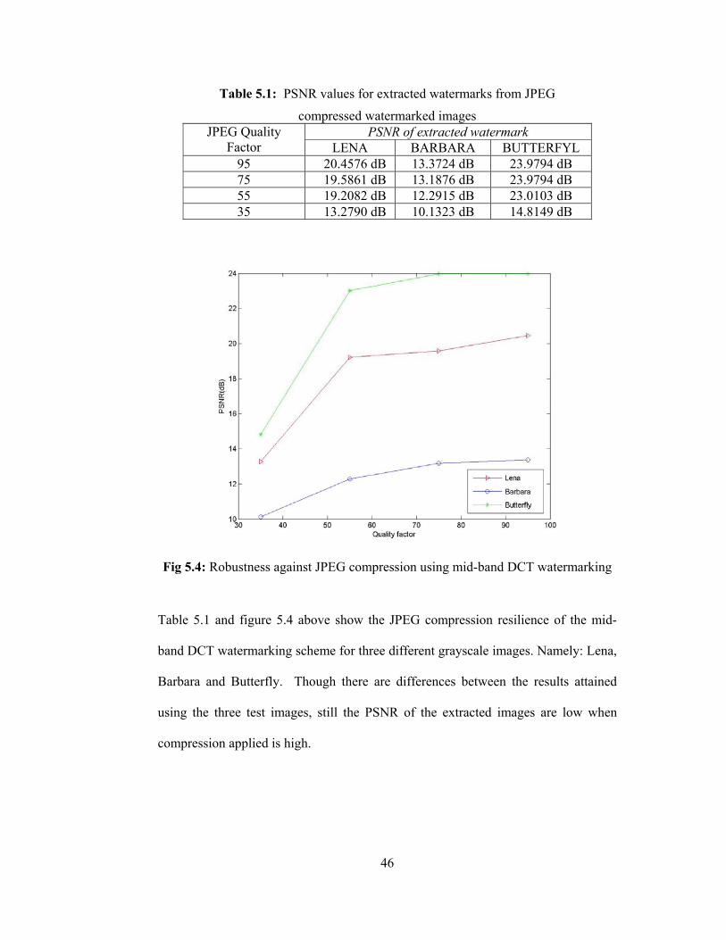
Table 5.1: PSNR values for extracted watermarks from JPEG
compressed watermarked images PSNR of extracted watermark JPEG Quality
Factor LENA BARBARA BUTTERFYL 95 20.4576 dB 13.3724 dB 23.9794 dB 75 19.5861 dB 13.1876 dB 23.9794 dB 55 19.2082 dB 12.2915 dB 23.0103 dB 35 13.2790 dB 10.1323 dB 14.8149 dB
Fig 5.4: Robustness against JPEG compression using mid-band DCT watermarking
Table 5.1 and figure 5.4 above show the JPEG compression resilience of the mid-
band DCT watermarking scheme for three different grayscale images. Namely: Lena,
Barbara and Butterfly. Though there are differences between the results attained
using the three test images, still the PSNR of the extracted images are low when
compression applied is high.
47
5.3 DCT domain DC-Component Based Watermarking In this section the grayscale images have been marked using the DCT domain DC-
components previously discussed in section 3.1. The payload, a (32 × 32) gray scale
image, has been embedded in some of the grayscale images in figure 5.1 and later
recovered. The watermark embedded images with their corresponding PSNR values
are shown in figure 5.5, whereas the recovered versions of the embedded payload are
as depicted in figure 5.6.
PSNR=40.1896 dB (a) Mandrill
PSNR=33.2404 dB (b) Barbara
PSNR=33.6505 dB (c) Goldhill
PSNR=43.6416 dB (d) Lena
PSNR=43.4019 dB (e) Peppers
Fig 5.5: DC-Component Based DCT Domain Watermarked Images
In figure 5.5, it is seen that PSNR values of watermarked images are not close to
each other. Images that are composed mostly of high frequency components, i.e.
Barbara and Goldhill, the magnitude of the DC coefficient is lower and hence PSNR
is also comparatively lover. On the other hand images that are composed mostly of
48
low frequency components, i.e. Lena, Peppers and Mandrill, the magnitude of the
DC coefficient is higher which implies higher perceptual capacity and also the
texture is stronger. These two factors lead to higher PSNRs in comparison to Barbara
and Goldhill.
original from (a) from (b) from (c) From (d) from (e)
Fig 5.6: The original and extracted watermarks from stego grayscale images
The PSNR values computed for the extracted marks in comparison to the original
mark are as shown in table 5.2. In comparison to results in table 5.1 the extracted
watermarks using the DCT domain DC-component based watermarking technique
are much higher.
Table 5.2: PSNR values for watermarks extracted from grayscale images
Cover Data PSNR (dB) of watermark extracted Baboon 59.1275 Barbara 55.8285 Gold Hill 55.8045 Lena 58.4834 Peppers 54.9360
5.3.1 DCT domain DC-Component Based Watermarking of color images In this section we have extended the use of DCT domain DC-component based
watermarking technique from grayscale to color images depicted in figure 5.2. Since
it is a know fact that the human eye is less sensitive to changes in the blue band the
blue component of the RGB images have been used for embedding the watermark.
As payload a (64 ×64) grayscale image reading “EMU EEE 2006 Fahri” was used.
49
PSNR= 33.9314
(a) Avion PSNR= 52.0268
(b) Mandrill
PSNR=46.8728 (c) Green Peace
PSNR= 32.6622 (d) Lena
Fig 5.7: PSNR for DC-component based watermarked color images
The watermark embedded images with their corresponding PSNR values are shown
in figure 5.7, and figure 5.8 show the recovered watermark from each of the four
stego images. The PSNR values computed for the extracted marks in comparison to
the original mark are also given in table 5.3.
Original from (a) from (b) from(c) from (d)
Fig 5.8: Watermarks extracted from stego color images
50
Table 5.3: PSNR values for watermarks extracted from color images
Color Cover Data PSNR (dB) of watermark extracted Avion 58.5708 Baboon 60.3032 Green Peace 59.7603 Lena 56.6957
5.3.2 Robustness Test against JPEG compression To assess the robustness against JPEG compression the DCT domain DC-component
based watermarking algorithm has been tested using the color images of the previous
subsection. The JPEG quality factor was introduced using the “Imwrite” command of
MATLAB and values were selected from the range 10-90. The PSNR values for the
extracted watermarks have been computed for all the images and are as seen in figure
5.9.
Fig 5.9: Robustness of DC-coefficient watermarking against JPEG compression
In comparison to the DCT domain mid-band component based watermarking, it is
clear that the DC-component based watermarking is much more robust against JPEG
51
compression. A PSNR of 35-38 dB is still possible for the extracted watermark at a
Q-factor value of 30.
5.3.3 Cropping Resilience Test In order to make the watermarking more robust against cropping it is possible to
embed the payload multiple times at different locations. In this work we embedded
four copies, one to each quarter of the image as depicted by figure 5.10.
Fig 5.10: Watermarking using multiple copies of the authentication data
Figure 5.12 and 5.13 shows the attacked image after all-round and diagonal
cropping. The all-round cropping is a severe attack since 75 % of the watermarked
image will be removed. Even under such a severe attack it is still possible to recover
the embedded mark fully by combining the extracted parts shown in figure 5.12 (d)-
(g) as below:
Fig 5.11: Re-assembling the authentication data from extracted parts
52
(a) (b) (c)
(d) (e) (f) (g)
Fig 5.12: All-round Cropping
(a) (b) (c)
(d) (e) (f) (g)
Fig 5.13: Diagonal Cropping
5.4 Template based DFT domain watermarking technique An important problem constraining the practical exploitation of watermarking
technology is the low robustness of existing watermarking algorithms against
53
geometrical distortions such as cropping, rotation, scaling and change of aspect ratio.
Sections below test the template based hybrid watermarking algorithm under
different attacks.
5.4.1 Detecting angle of Rotation
The algorithm for calculating the rotation angle depends on detecting the two
template lines from the Fourier transformed version of the attacked image. After the
extraction of the local peaks, their positions are firstly mapped to polar coordinates
and then peaks are sorted by angle into 360 equally spaced bins. From these angle
bins those with at least five peaks that match the radius patterns of one of the two
template lines is accepted as a matched line. Finally from all combinations of sets of
matched lines only two satisfying an angle difference of 21 θθ − is chosen.
During simulations Barbara and Butterfly images were intentionally rotated by 65
and 25 degrees and the above described algorithm applied in order to find the correct
template lines. As depicted in figures 5.14 and 5.15 the algorithm is successful in
finding the rotation angle and correcting the orientation of the attacked image.
54
(a) Original (b) Template Embedded (b) Attacked
(d) peak map (b) Restored Image
Fig 5.14: 65° rotation attack
55
(a) Original (b) Template Embedded (b) Attacked
(d) peak map (b) Restored Image
Fig 5.15: 25° rotation attack
5.4.2 Constant Scaling in both directions For scaling tests a watermarked and template added version of the (512 × 512) image
of ROBIN was used. Two different types of scaling were applied. In the first type the
image was scaled in both the horizontal and vertical directions using a fixed scaling
factor to keep the aspect ratio same. Results obtained using the method described in
56
section 4.6 is as depicted in table 5.4. Figure 5.16 also gives a snapshot of the
attacked and restored images for a scale factor of 0.7.
Table 5.4: Restored size and MSE values after scaling attack
We note that in either case the image restored does not have the same dimensions as
the original watermarked image before the attack. The small changes in aspect ratio
are incurred as a result of rounding errors.
5.5 Hybrid Watermarking Technique In section 5.3 it was shown that the DC-component based Discrete Cosine Transform
domain watermarking is very efficient against JPEG compression. However the
accuracy of the template based DFT domain technique described by [25] in
estimating the affine transform parameters for scaling is not perfect. The error
incurred is due to the rounding that takes place when an image is re-scaled in spatial
domain using non-integer scale factors. Step-5 of the template detection algorithm of
section 4.6 requires computing the absolute difference shown in equation (5.2). For a
small threshold value it will be possible to obtain a good estimate of K (the
reciprocal of the scaling factor) if the absolute difference is smaller than a selected
threshold value.
thresholdrKr Tji <⋅− (5.2)
For instance a size (512×512) digital image that is scaled down by a factor of 0.6 will
assume the size (308×308) since the grid is composed of integer valued locations
(512*0.6 = 307.2). As shown in table 5.6 a point on the original template at
coordinates (72,96) may map into one of two sets of coordinates after taking the
transform of the attacked image zero padded to the original image size. The reverse
of scaling factor 0.6 is 1.66666666 so with K at three digits accuracy after the
decimal point and rTj=120 there will be two different values for the absolute
59
difference. One of these will satisfy the threshold constraint but the other will not do
so stopping the convergence of affine transform parameters to the correct ones.
Table 5.6: Effect of rounding errors on the absolute difference value
Coordinates of a template point in DFT transformed original image
Coordinates for the corresponding template point after transforming the padded attacked image (119.52 , 159.36) (119.68 , 159.58) After rounding (120 , 159) 2009.1991 =⇒ rad (120 , 160) 2002 =⇒ rad
(72,96)
K= 0.5 : 0.001: 2 Current K = 1.666 Threshold =0.09
09.07191.092.1992009.199
09.008.092.199200
>=−
<=−
The proposed hybrid method can be demonstrated for rotation, cropping, and scaling
attacks.
We demonstrated the applicability of the hybrid watermarking method using two
color test images. Firstly a (64×64) watermark was inserted in the blue channel of the
RGB images and then the synchronization template was embedded in their respective
red channels. Afterwards the watermarked and template embedded images were
intentionally rotated by -35 and 15 degrees respectively. A MATLAB program
detected the rotation angle and the watermark embedded was then extracted from the
restores images. The results obtained are depicted in figures 5.18 and 5.19.
60
Original Watermark to insert
Watermark in blue channel
Watermark and Template Embedded
attacked Restored -35 Extracted watermark
Fig 5.18: Proposed Hybrid Watermarking applied with a 35 degree attack
Similarity values computed for the extracted watermarks are 0.9425 for
GREENPEACE test image and 0.9573 for the MANDRILL. The only discrepancy is
that some of the high frequency components of the original cover data can also be
observed in the extracted watermarks. A possible solution will be to lowpass filter
the output or to pass it through a median filter. However in general we can say that
the proposed method works well.
61
Original Watermark to insert
Watermark in blue channel
Watermark and Template
Embedded
Attacked image Restored 15 Extracted watermark
Fig 5.19: Proposed Hybrid Watermarking applied with a -15 degree attack
For scaling tests a watermarked and template added version of the (512 × 512)
images of LENA and AVION were used. Two different types of scaling were
applied. In the first type the image was scaled in both the horizontal and vertical
directions using a fixed scaling factor of 0.7 to keep the aspect ratio same. Scaling
attack not preserving the aspect ratio was also tested for the horizontal and vertical
scale factors of X = 0.9 and Y = 0.7. In either case as can be seen from figure 5.20
the extraction of the inserted watermark is possible.
62
Attacked Image: (359 × 359) (a)
Restored Image:(511 × 513) (b)
Extracted Watermark
(c)
Attacked Image: (461×359) (d)
Restored Image: (511×512) (e)
Extracted Watermark
(f)
Fig 5.20: Recovery from Scaling Attacks
63
CHAPTER 6
6 CONCLUSIONS & FUTURE WORK
The work carried out indicates that the DC-component based discrete cosine
transform domain watermarking technique is much more robust against JPEG
compression when compared to the mid-band frequency based DCT domain
watermarking technique.
Embedding the authentication mark multiple times in different location in the cover
data makes the watermarking much more robust against cropping. Even with all
round cropping where 75% of the image is removed it is still possible to get the full
mark by re- ordering the extracted parts. The only disadvantage here may be that the
size of the payload will be smaller when multiple copies are to be embedded.
The use of a synchronization template in the DFT domain provides a tool for
estimating and correcting the affine transformations that the image may have been
subjected to.
As demonstrated in section 5.5 the proposed hybrid watermarking algorithm is robust
against compression, rotation translation and scaling attacks. The only problem faced
is that recovery from scaling attacks is not perfect due to the rounding errors as
previously explained. Hence the future work will try to engineer a way in better
estimating the affine transform parameters for scaling.
64
Also for decreasing the computational cost of template matching algorithm, a future
work is suggested by Pereira; using a pruned exhaustive search instead of binning by
angle, and detecting local peaks by taking local maximum of every 5×5 window in
the DFT domain instead of a harmful search.
65
REFERENCES
[1] Kundur D., Hatzinakos D., “A robust digital image watermarking method
using wavelet-based fusion,” Int. Conf. on Image Processing, Vol. 1, Oct 1997, pp. 544-547.
[2] Cox I. J., Kilian J., Leighton F. T., & Shamoon T., “Secure Spread Spectrum
Watermarking for Multimedia,” IEEE Transactions on Image Processing, Vol. 6, No: 12, Dec 1997, pp. 1673-1687.
[3] Tirkel A.Z.., Rankin G. A., Schyndel R.G. van, Ho W.J., Mee N.R.A., and
Osborne C.F., “Electronic Watermark,” In Dicta-93, Dec 1993, pp. 666-672. [4] Bender W., Gruhl D., and Morimoto N., “Method and apparatus for data
hiding in images,” U.S. Patent # 5689587, 1996. [5] Goffin F., Delaigle J.F., De Vleeschouwer C., Marc B., and Quisquater J.J.,
“A low cost perceptive digital picture watermarking method,” Storage and Retrieval for Image and Video Database, Vol. 3022, Feb 1997, pp. 264-277.
[6] Kutter M., Jordan F., & Bossen F., “Digital signature of color images using
amplitude modulation,” Proc. of SPIE-EI 97, Feb 1997, pp. 518-526. [7] Cox I. J., Miller M. L., and McKellips A. L., “Watermarking as
Communications with Side Information,” Proc. of IEEE, Vol. 87, No: 7, July 1999, pp. 1127-1141.
[8] Ho A.T.S., Jun S., Soon H. T., & Kot A.C., “Digital image-in-image
watermarking for copyright protection of satellite images using the fast Hadamard transform,” IEEE International Geoscience and Remote Sensing Symposium (IGARSS '02), 24-28 June 2002, Vol. 6, pp. 3311-3313.
[9] Hsu C. T., and Wu J.L., “Hidden digital watermarks in images,” IEEE
Transactions on Image Processing, Vol. 8, No: 1, Jan 1999, pp. 58-68. [10] Nikolaidis N., & Pitas I., “Copyright Protection of Images Using Robust
Digital Signatures,” IEEE International Conference on Acoustics, Speech, and Signal Processing, 7-10 May 1996, Vol. 4, pp. 2168-2171.
[11] Piva A., Bartolini F., Cappellini V., & Barni M., “Exploiting the cross-
correlation of RGB-channels for robust watermarking of color images,” International Conference on Image Processing, 1999, Vol. 1, pp. 306-310.
66
[12] Puertpan R., & Amornraksa T.,“Gaussian pixel weighting marks in amplitude modulation of color image watermarking,” International Symposium on Signal Processing and its Applications, 13-16 Aug 2001, Vol. 1, pp.194-197.
[13] Fleet J. D., and Heeger D. J., “Embedding Invisible Information in Color
Images,” Inter. Conf. on Image Processing, Vol. 1, 26-29 Oct 1997, pp. 532-535.
[14] Piva A., Bartolini F., Cappellini V., and Barni M., “Exploiting the cross-
correlation of RGB-channels for robust watermarking of color images,” Inter. Conf. on Image Processing, Vol. 1, 1999, pp. 306-310.
[15] Hwang R-J., Kao C-H., & Chang R-C., “Watermark in color image,”
Proceedings of the 1st International Symposium on Cyber Worlds, 6-8 Nov 2002, pp. 225-229.
[16] Coltuc D., & Bolon P., “Color Image Watermarking in HSI Space,”
International Conference on Image Processing, 10-13 Sept 2000, Vol. 3, pp. 698-701.
[17] Chou C-H., & Liu K-C., “Color image watermarking based on a color visual
model,” IEEE Workshop on Multimedia Signal Processing, 9-11 Dec 2002, Vol. 1, pp. 367-370.
[18] Huang J., Shi Q. Y., & Shi Y., “Embedding Image Watermarks in DC
Components,” IEEE Transactions on Circuits and Systems for Video Technology,” Vol. 10, No: 6, Sept 2000, pp. 974-979.
[19] Lu H., Shi X., Shi Y. Q., Kot A. C., & Chen L. “Watermark Embedding in
DC Components of DCT for Binary Images,” IEEE Workshop on Multimedia Signal Processing, 9-11 Dec 2002, pp. 300-303.
[20] Deng F., & Wang B., “A Novel Technique For Robust Image Watermarking
In the DCT Domain,” IEEE Int. Conf. on Neural Networks & Signal Processing, Nanjing-China, 14-17 Dec 2003, pp. 1525-1528.
[21] Lin S. D., & Chen C-F., “A Robust DCT-Based Watermarking For Copyright
Protection,” IEEE Transactions on Consumer Electronics, Vol. 46, No: 3, Aug 2000, pp. 415-421.
Reliability Using Filtering Before Correlation,” International Conference on Image Processing, ICIP 98, 4-7 Oct 1998, Vol. 1, pp. 430 – 434.
[23] O’Ruanaidh J. J.K., & Pun T., “Rotation, scale and translation invariant
digital image watermarking,” International Conference on Image Processing, 26-29 Oct 1997, Vol. 1, pp. 536-539.
67
[24] Qi J., & Qi X., “Improved Affine Resistant Watermarking By Using Robust Templates,” IEEE International Conference on Acoustics, Speech, and Signal Processing, 17-21 May 2004, Vol. 3, pp. 405-408.
[25] Pereira S., & Pun T., “Robust Template Matching for Affine Resistant Image
Watermarks,” IEEE Trans. On Image Processing, June 2000, Vol. 9, No: 6, pp.1123-1129.
[26] Pereira S., & Pun T., “Fast robust template matching for affine resistant
image watermarking,” Int. Workshop on Information Hiding, Dresden, Germany, Sept. 29 - Oct. 1, 1999, Lecture Notes in Computer Science, LNCS 1768, pp. 200-210.
[27] Pereira S., Pun T., “An iterative template matching algorithm using the
Chirp-Z transform for digital image watermarking,” Pattern Recognition, 33(1), Jan 2000.
[28] Shim H. J., & Jeon B., “Rotation, Scaling and Translation Robust Image
Watermarking Using Gabor Kernels,” Security and Watermarking of Multimedia Contents IV, SPIE 2002, Vol. 4675, pp. 563-571.
[29] Deguillaume F., Voloshynovskiy S., & Pun T., “A method for the estimation
and recovering from general affine transforms in digital watermarking applications,” SPIE Photonics West, Electronic Imaging 2002, Security and Watermarking of Multimedia Contents IV, San Jose-CA, 20-25 Jan 2002, Vol. 4675, pp. 34-40.
[30] Zheng D., Liu Y., & Zhao J., “RST invariant digital image watermarking
based on the new phase-only filtering method,” International Conference on Signal Processing, 31 Aug - 4 Sept 2004, Vol. 1, pp. 25-28.
[31] Solachidis V., Pitas I., “Circular Symmetric Watermark Embedding in 2D
DFT Domain,” IEEE Transactions on Image Processing, Nov 2001, Vol. 10, No: 11, pp. 1741-1753.
[32] Licks V., & Jordan R., “On digital Image Watermarking Robust To
Geometric Transformations,” International Conference on Image Processing, 10-13 Sept 2000, Vol. 3, pp. 690-693.
[33] Alattar A.M., & Meyer J., “Watermark re-synchronization using log-polar
mapping of image autocorrelation,” International Symposium on Circuits and Systems, 25-28 May 2003, Vol. 2, pp. II-928- II-931.
of Fourier-Based Watermarks Using Log-Polar and Log-Log Maps,” IEEE International Conference on Multimedia Computing and Systems, 7-11 June 1999, Vol. 1, pp. 870-874.
68
[35] Kaewkamnerd N., Rao K.R., “Wavelet based watermarking detection using multiresolution image registration,” Proc. of TENCON, Vol. 2, Sept 2000, pp. 171-175.
[36] Kutter M., Bhattacharjee S. K., & Ebrahimi T., “Towards Second Generation
Watermarking Schemes,” IEEE International Conference on Image Processing (ICIP), Vol. 1, 1999, pp. 320 – 323.
[37] Loo, P., & Kingsbury N., “Watermarking using complex wavelets with
resistance to geometric distortion,” European Signal Processing Conference, 4-8 Aug 2000.
[38] Shi Y.Q., Sun H., Image and Video Compression for Multimedia
Engineering: Fundamentals, Algorithms and Standards, Boca Raton, FL: CRC, 1999.
[39] Langelaar G. C., Setyawan I., & Lagendijk R. L., “Watermarking Digital
Image and Video Data,” IEEE Signal Processing Magazine, Vol. 17, No: 5, Sept 2000, pp. 20-46.
[40] Kutter M., & Petitcolas F.A.P., “A fair benchmark for image watermarking
systems,” Security and Watermarking of Multimedia Contents, 25-27 Jan 1999, Vol. 3657, pp. 1-14.
[41] Cox I.J., & Miller M. L., “The first 50 years of electronic watermarking,”
Journal of Applied Signal Processing, 2002, Vol. 2, pp. 126-132.
[42] WatermarkingWorld.Com, Retrieved November 2005, from http://www.watermarkingworld.org


![Geometry Affine[1] Acuan](https://static.documents.pub/doc/80x56/563db91d550346aa9a9a289f/geometry-affine1-acuan.jpg)


