8/31/2015 Compression Principles & Gas Compressors http://articles.compressionjobs.com/articles/oilfield101/163compressioncompressorscentrifugalreciprocatingprinciples?tmpl=component&print=1&page= 1/10 Compression Principles & Gas Compressors Written by Norrie Wednesday, 13 January 2010 09:26 INTRODUCTION In many industries, compressors are used to add energy to gases in the form of pressure for various uses and processes. Compressors of many, varied types are utilised for this purpose. In some cases, high pressure is needed in order to liquefy a gas. This is often carried out to greatly decrease the volume of the gas to allow storage and transportation of the liquids to anywhere in the world. For example, Propane and Butane gases are compressed and cooled until they change to liquid. This is the process used to produce Liquid Petroleum Gas (LPG) which is used commercially and domestically as fuel for a great number of purposes. Since fairly recently, Natural Gas (Mainly Methane & Ethane) is being liquefied to produce Liquid Natural Gas (LNG). To produce Liquid Natural Gas (LNG), the gas at high pressure is cooled to about 265°F (165°C). The liquid can then be stored in special insulated tanks at just above atmospheric pressure. The tankers used for transportation of LNG are also specially built for the job. In liquid form, natural gas can be transported by specially built tankers to countries with little or no natural resources for industrial and domestic use. The liquid is revaporised and distributed by pipeline grids to the users. There are a number of types of compressors used for the purpose of adding pressure energy to gases, the most common are: A. CENTRIFUGAL B. AXIAL FLOW C. RECIPROCATING (PISTON) TYPES A. CENTRIFUGAL & CENTRIPETAL FORCES Consider a ball attached to a bar which is able to rotate on a shaft, the ball, due to centrifugal force, will move upwards and outwards and try to fly away from the shaft. This is explained in Figure: 1. When a body is set in motion, if there is no pull of gravity, no friction and no obstacle to deflect it, the body will continue to move in a straight line. We will now fasten a string to a ball and a fixed pivot point and set the ball in motion. As the string becomes taut, the ball will be deflected and will travel in an arc or circle. If the ball has been given enough momentum (energy), it will continue to move in a series of arcs in such a way that, at each instant of its
Transcript
8/31/2015 Compression Principles & Gas Compressors
Compression Principles & Gas CompressorsWritten by Norrie
Wednesday, 13 January 2010 09:26
INTRODUCTION
In many industries, compressors are used to add energy to gases in the form of pressure for various uses andprocesses. Compressors of many, varied types are utilised for this purpose.In some cases, high pressure is needed in order to liquefy a gas. This is often carried out to greatly decrease thevolume of the gas to allow storage and transportation of the liquids to anywhere in the world.For example, Propane and Butane gases are compressed and cooled until they change to liquid. This is the processused to produce Liquid Petroleum Gas (LPG) which is used commercially and domestically as fuel for a great numberof purposes.Since fairly recently, Natural Gas (Mainly Methane & Ethane) is being liquefied to produce Liquid Natural Gas(LNG). To produce Liquid Natural Gas (LNG), the gas at high pressure is cooled to about 265°F (165°C). Theliquid can then be stored in special insulated tanks at just above atmospheric pressure. The tankers used fortransportation of LNG are also specially built for the job. In liquid form, natural gas can be transported by speciallybuilt tankers to countries with little or no natural resources for industrial and domestic use. The liquid is revaporisedand distributed by pipeline grids to the users. There are a number of types of compressors used for the purpose of
adding pressure energy to gases, the most common are:
A. CENTRIFUGALB. AXIAL FLOWC. RECIPROCATING (PISTON) TYPES
A. CENTRIFUGAL & CENTRIPETAL FORCES
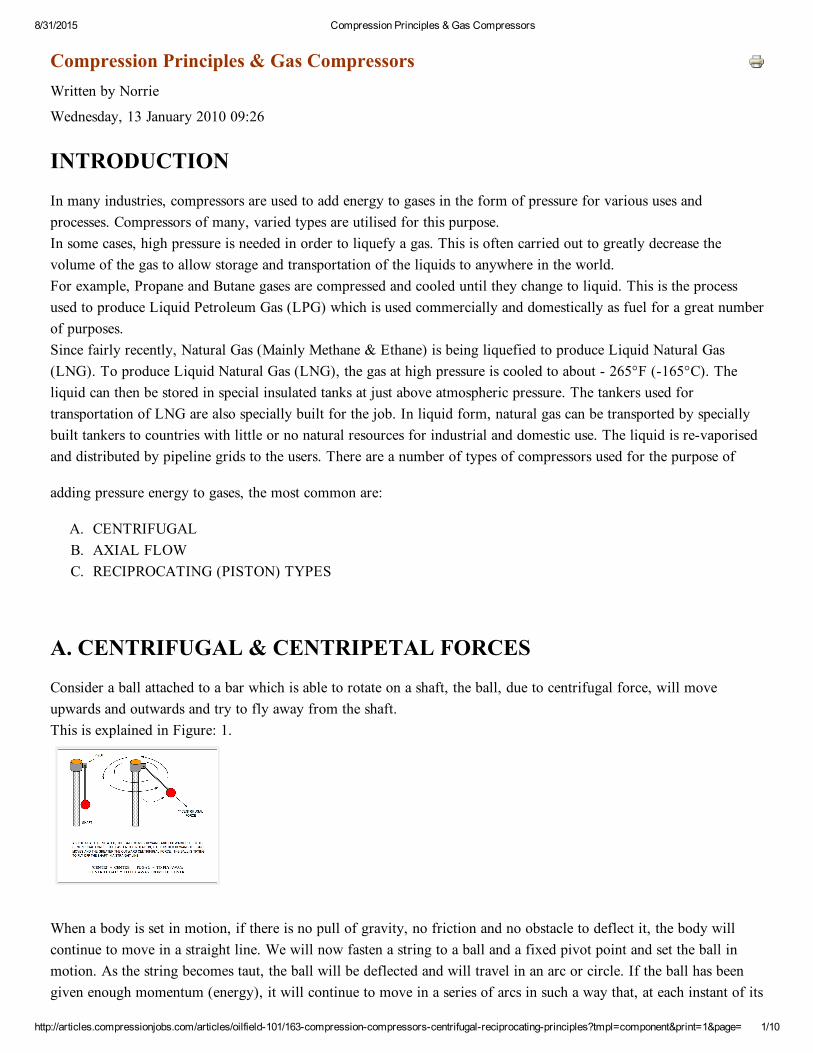
Consider a ball attached to a bar which is able to rotate on a shaft, the ball, due to centrifugal force, will moveupwards and outwards and try to fly away from the shaft.This is explained in Figure: 1.
When a body is set in motion, if there is no pull of gravity, no friction and no obstacle to deflect it, the body willcontinue to move in a straight line. We will now fasten a string to a ball and a fixed pivot point and set the ball inmotion. As the string becomes taut, the ball will be deflected and will travel in an arc or circle. If the ball has beengiven enough momentum (energy), it will continue to move in a series of arcs in such a way that, at each instant of its
8/31/2015 Compression Principles & Gas Compressors
travel, the ball tends to move in a straight line, but instead, because the string is taut and causing deflection, the ballmoves in a circle.
The string is applying a 'Centripetal' force (pullingintowardsthecentre) that causes the path of the ball to changeor curve. Should the string break, the ball will fly off in a straight line.(See Figure: 2.)
Any object travelling in a circle, is kept in that path of travel by this centripetal force. (The moon continues aroundthe earth due to the centripetal effect of the earth's pull of gravity).
Figure: 3: Gives a basic, simplified idea of the operation of a centrifugal compressor.
The use of a single impeller (or wheel) as a centrifugal compressor is not common as it cannot produce muchpressure.
B. CENTRIFUGAL COMPRESSION & COMPRESSORS
For high power industrial use, a compressor has more than one impeller mounted on the shaft and generally, four ormore wheels are used. These are called 'Multistage Compressors' where each impeller is referred to as a 'Stage' andthe stages and shaft make up the 'Rotating Element' or 'Rotor' of the machine. Again, a machine consisting ofimpellers only does not make up a compressor. The rotor must be enclosed in a 'Casing' or 'Housing' in which therotor is spun at high speed.In the following diagram, Figure: 4, the rotor is enclosed in a casing. If the rotor is spun at high speed, not much willhappen because the gas at this point will not be compressed – it will simply spin around like the fluids in a kitchenblender.
8/31/2015 Compression Principles & Gas Compressors
The system now needs a means of compressing the gas as it is driven through the casing by the rotor. This is achievedby guiding the gas flow into the impeller eyes by a 'Diaphragm', as part of the casing, placed between each impeller.
PARTS of a CENTRIFUGAL COMPRESSOR
A centrifugal compressor is built up of TWO MAIN PARTS :
1. THE ROTOR (or Rotating Element)2. THE CASING (or Housing or Body)
1. THE ROTOR
One of the greatest advantages of a centrifugal compressor is that it has very few moving parts, which minimizesmechanical problems and energy losses due to friction. Other than the bearings, (and of course, the driver), the onlymoving part in a centrifugal compressor is the Rotor.
The Rotor (rotating element), is made up of one or more impellers (or wheels) mounted (fixed) onto a shaft. Acompressor having a single impeller is called a 'Singlestage' machine. This type is generally used as a 'Blower' or'Fan', due to the small increase in pressure of air or gas across the single wheel.
The Impellers : These consist of wheelshaped elements containing 'Vanes' at the centre of which is the gas inlet calledthe 'EYE' of the impeller. The impeller is mounted on the shaft which is connected to the driver. As it rotates at highspeed, the gas is thrown off the outer edge of the vanes, and more gas flows into the eye to take its place. The speedof rotation of the wheel imparts kinetic energy to the gas in the form of velocity which will be converted to pressure(potential) energy.
In modern industry, where large volumes of high pressure gas are processed, the compressors consist of a number ofimpellers on the same shaft. These are called 'Multistage Compressors'. The discharge pressure of such a machinedepends upon the number of impellers and the speed of rotation more impellers and/or more speed gives higherdischarge pressure. The volume of gas moved capacity of the machine, depends upon its physical size.
Through a multistage compressor, the pressure is built up from stage to stage and, as it increases, the volume of thegas decreases. Because of the volume decrease after each stage, the wheels become progressively narrower and, afterthe final stage the gas is passed into the discharge line. Again, due to increased pressure and decreased volume, thedischarge line has a smaller diameter than the suction line.
8/31/2015 Compression Principles & Gas Compressors
The Rotor or Rotating Element is housed in the compressor 'CASING' supported by bearings, and is coupled(connected) to the driver. The driver imparts rotation to the rotor. Where the shaft extends to the outside of thecasing, seals are fitted to minimize leakage to the atmosphere. The high velocity gas leaves each wheel at rightanglesto the rotor and is therefore travelling in the wrong direction for entry into the next stage.
2. THE CASING (Housing or Body)
The casing houses the rotor and is made up of the following:
DIAPHRAGMSThese separate the stages (wheels) of the rotor. Between each stage and the shaft, the diaphragms are fitted withlabyrinth seals in order to minimize leakage between the stages, of HP gas to the LP side of the wheel. Thediaphragms also hold the 'DIFFUSERS'. In the diffusers, the velocity of the gas is decreased causing the molecules ofgas to 'crowd' together which causes a pressure increase (Bernoulli's Principle Velocity Decrease , PressureIncrease). Following the diffusers within the diaphragms, are the 'RETURN PASSAGES' where the gas, as it leavesthe diffuser, is directed into the eye of the next impeller. After the final stage, the gas, at the required pressure, ispassed into the discharge nozzle and piping.The diagram, (Figure: 5), shows a simplified idea of the layout of a 5stage centrifugal compressor.
In the diagram, note the larger size of the suction inlet nozzle as compared to the discharge nozzle. Also note thesuccessive narrowing of the impellers from the suction end to the discharge end. This is to allow for the increase inpressure and therefore the decrease in volume of the gas as it passes through the compressor.
** IT SHOULD BE NOTED AT THIS POINT THAT LIQUIDS AND SOLIDS MUST NEVER BEALLOWEDTO ENTER THE COMPRESSOR. EVEN TINY DROPLETS OF LIQUID AND VERY FINE PARTICLES OFSOLIDS, DUE TO THEIR HIGH VELOCITY, WILL CAUSE SERIOUS EROSION OF THE MACHINEINTERNALS ROTOR, IMPELLER BLADES & SHROUDS, DIAPHRAGM PARTS .. ETC. **
The Figures 5, 6 and 7 show more details of the layout of centrifugal compressors.
8/31/2015 Compression Principles & Gas Compressors
The above diagram gives a simplified explanation of the 'Balance Drum' and 'Balance Line' in the HP end of acentrifugal compressor. HP gas leakage would tend to migrate through the labyrinth seals into the HP end shaft sealand bearing housing.
The balance drum and line bleed any leakage back to the compressor suction line. The HP end seal will therefore stayat the same pressure as the LP end seal (suction pressure) and the sealing medium will help prevent gas leakage intothe bearings.
SURGING IN A CENTRIFUGAL COMPRESSOR
'Surging' is defined as 'A momentary backflow' through the compressor from the discharge to the suction. This canoccur when the mass flow of gas to the compressor falls below a critical level with a high pressure difference acrossthe machine. When there is not enough gas to replace that being pushed forward, discharge gas will flow backwardsthrough the compressor towards the suction side. This backflow will tend to decrease the speed of rotation while thespeed controller will try to maintain the correct speed. The gas flowing backward provides more volume to thesuction side and the compressor picks up and begins to push gas forward again. The machine speed will tend toincrease and the governor will again try to maintain the correct, set speed. All of this takes place very quickly; thebackward and forward gas flow together with the speed control action causes rapid fluctuations in the flow andpressure of the system. This 'Surging' in the machine can be very damaging to the compressor and associated pipingand equipment due to heavy vibrations set up in the system. Generally, if the suction flow drops too low, a 'LowflowTrip' will shut down the machine. Also, surging can cause the machine to 'Overspeed' before the control system canreact. This can also cause damage and is prevented by an 'Overspeed Trip Mechanism' which will again shut down themachine.These problems of Surging are usually prevented by an 'Antisurge' system and control valve which, externally,recycles discharge gas back to the suction side in order to maintain a 'Minimum Flow Rate' to the machine. Becausecompression causes temperature increase, this recycle gas is normally taken from the discharge side, downstream of
8/31/2015 Compression Principles & Gas Compressors
the aftercooler, in order to prevent greater and greater temperature increase at the discharge side.In large, powerful machines, the antisurge system is computer controlled and depends upon data received from thefollowing: Gas Flow rate, Suction pressure and Temperature, Discharge Pressure and the Density (or S.G.) of thegas entering the machine.Figure: 8, on the following page gives a general idea of an antisurge system.
In the above picture the Combustion Gas Turbine consists of an Axial Flow air compressor, a High Pressure (HP)Compressor Turbine and a Low Pressure (LP) Load Turbine. Six fuel fired Combustion Chambers, (3 each side),provide the heat input into the air compressor discharge and the superheated air provides the required energy to drivethe HP turbine. The hot gases give up energy in driving the HP turbine but, sufficient remains in the hot gases todrive the LP (load) turbine. The LP turbine is connected by a shaft to the 'Load' which, in this case, is two, multistage, natural gas compressors driven in 'Tandem'.
C. AXIAL FLOW COMPRESSORS
Where the discharge of the wheels of a centrifugal compressor leaves at right angles to the wheel, in an axial flowmachine, the flow of gas is parallel to the rotor. Imagine a series of fans placed in front of each other. When they areoperating, the flow of air from the first fan is fed into the second fan which further increases the flow of air. This isrepeated through the series of fans tending to give a much increased air flow from the final fan.The rotor of an Axial Flow compressor consists of a number of stages (or rows) of many ‘ROTOR’ (Rotating) bladesfitted at an angle into the rotor body – similar to the blades of a fan. The blades in each row become smaller andnarrower from stage to stage. This arrangement allows for the decrease in volume of the gas as its pressure increasesfrom stage to stage. However, as the gas leaves each stage, it is moving at high velocity and in the opposite directionto the rotation of next stage. In the casing of the machine, rows of ‘STATOR’ (Static) blades are fitted in diaphragmsplaced at an opposite angle to the rotor blades between the rotor stages.
These Stator blades have two purposes;
1. To decrease the velocity of the gas – thereby increasing pressure (Bernoulli's Principle).2. To redirect the flow of gas into the blades of the next stage.
8/31/2015 Compression Principles & Gas Compressors
This arrangement pushes the gas Axially along the length of the machine increasing pressure from stage to stage. Thedischarge pressure from the final stage will depend upon the number of stages in the compressor and/or the machinespeed. The volume of gas compressed depends on the physical size of the compressor. This type of compressor isgenerally utilised in the air compressor section of a Combustion Gas Turbine.The following pictures (Figures: 9, 10, & 11) show some internal arrangements of Axial FlowCompressors.
Figure: 11 View of Axial Flow Compressor Internals
Figure: 12 Simplified Diagram of an Axial Flow Compressor
D. RECIPROCATING ( PISTON ) COMPRESSORS (PositiveDisplacement Compressors)
'Reciprocation' means 'Backward and Forward Motion'. A 'Reciprocating' compressor therefore, is one with a forwardand backward operating action. The simplest example is the 'Bicycle pump', which everyone at some time or other
8/31/2015 Compression Principles & Gas Compressors
will have used to reinflate their bike tyres. The name 'Bicycle PUMP' is not really the correct term because it causescompression.It is essentially a hand operated compressor and consists of a metal or plastic tube called a 'Cylinder' inside of which ahandoperated piston rod or 'SHAFT' is pushed back and forth. On the shaft end, inside the cylinder, a special leatheror rubber cup shaped attachment is fixed. When the piston is pushed forward, (this is called a 'Stroke'), the cupflexes against the cylinder walls giving a seal to prevent air passing to the other side. As the handle is pushed, airpressure builds up ahead of the cup and is forced (discharged ) into the tyre through the tyre valve which also preventsair escaping when the pump is disconnected or when the piston is pulled back. When the pump handle is pulled back,(called the 'Suction' stroke), the cup relaxes and the backward motion causes air to pass between it and the cylinderwall to replace the air pushed into the tyre. This 'reciprocating' action is repeated until the tyre is at the requiredpressure. Because the air is expelled from the pump during the forward stroke only, the compressor is known as'Single Acting, Reciprocating'.( See Figure : 13 )
SINGLE ACTING RECIPROCATING COMPRESSORS
In industry, reciprocating compressors are of many sizes and designs. Their operation is similar to the bicycle pumpdescribed above. An industrial reciprocating compressor is constructed of metal and has the following main parts :
1. THE CYLINDERThis is a metal tubeshaped casing (or body), which is generally fitted with a metal lining called a 'cylinder liner'. Theliner is replaceable when it becomes worn and inefficient. The cylinder is also fitted with suction and discharge portswhich contain special spring loaded valves to allow liquid to flow in one direction only similar to check valves.
2. THE PISTONThe piston consists of a metal drive rod connected to the piston head which is located inside the cylinder. The pistonhead is fitted with piston rings to give a seal against the cylinder lining and minimise internal leakage. The other endof the drive rod extends to the outside of the cylinder and is connected to the driver. Modern industry generally usedhigh power electric motors and gearing to convert the rotating motion into a reciprocating action.In a single acting compressor, the backward stroke of the piston causes a suction which pulls in gas (or air) throughthe inlet valve. (The same suction action keeps the discharge valve closed). On the forward stroke, the positivepressure generated by the piston, closes the inlet valve and opens the discharge valve. The liquid is displaced into thedischarge system. Because the action is positive displacement, a piston compressor can generate very high pressure andtherefore MUST NEVER be operated against a closed discharge system valve unless it is fitted with a safety reliefsystem in order to prevent damage to the compressor and/or the driver and/or other downstream equipment.( See Figure : 14 )
8/31/2015 Compression Principles & Gas Compressors
Figure : 14 Single Acting, Reciprocating Compressor (Simplified)
In the old days of piston pumps, the driver used to be (and still is in some cases), high pressure steam which was fedto drive double acting cylinders by a system of valves in a steam chest – like the driver of an old steam engine. Thereciprocating action is converted to rotation to drive the engine wheels. (See photograph below).
Figure : 15 – Conversion of Rotation to Reciprocation
DOUBLE ACTING RECIPROCATING COMPRESSORS
This type of compressor operates in exactly the same way as the single acting with respect to its action. The differenceis, that the cylinder has inlet and outlet ports at EACH END OF THE CYLINDER. As the piston moves forward,liquid is being drawn into the cylinder at the back end while, at the front end, liquid is being discharged. When thepiston direction is reversed, the sequence is reversed. With a double acting compressor, the output pulsation is muchless than in the single acting. ( See Figure : 16 )The speed of a reciprocating machine is generally measured as 'Strokes per Minute'. This is the number of times thepiston moves back and forth in one minute. Speed can also be measured as 'R.P.M.' of the drive motor. As thecylinder(s) are of constant dimensions, the volume of fluid moved for each stroke, is the same and therefore theoutput per minute, hour or day ..etc can be calculated.
8/31/2015 Compression Principles & Gas Compressors