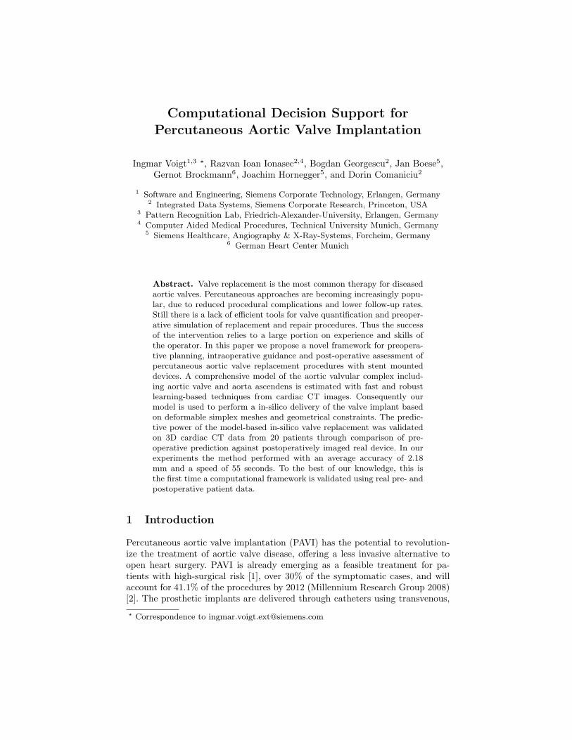
Computational Decision Support for Percutaneous Aortic Valve Implantation Ingmar Voigt 1,3 ? , Razvan Ioan Ionasec 2,4 , Bogdan Georgescu 2 , Jan Boese 5 , Gernot Brockmann 6 , Joachim Hornegger 5 , and Dorin Comaniciu 2 1 Software and Engineering, Siemens Corporate Technology, Erlangen, Germany 2 Integrated Data Systems, Siemens Corporate Research, Princeton, USA 3 Pattern Recognition Lab, Friedrich-Alexander-University, Erlangen, Germany 4 Computer Aided Medical Procedures, Technical University Munich, Germany 5 Siemens Healthcare, Angiography & X-Ray-Systems, Forcheim, Germany 6 German Heart Center Munich Abstract. Valve replacement is the most common therapy for diseased aortic valves. Percutaneous approaches are becoming increasingly popu- lar, due to reduced procedural complications and lower follow-up rates. Still there is a lack of efficient tools for valve quantification and preoper- ative simulation of replacement and repair procedures. Thus the success of the intervention relies to a large portion on experience and skills of the operator. In this paper we propose a novel framework for preopera- tive planning, intraoperative guidance and post-operative assessment of percutaneous aortic valve replacement procedures with stent mounted devices. A comprehensive model of the aortic valvular complex includ- ing aortic valve and aorta ascendens is estimated with fast and robust learning-based techniques from cardiac CT images. Consequently our model is used to perform a in-silico delivery of the valve implant based on deformable simplex meshes and geometrical constraints. The predic- tive power of the model-based in-silico valve replacement was validated on 3D cardiac CT data from 20 patients through comparison of pre- operative prediction against postoperatively imaged real device. In our experiments the method performed with an average accuracy of 2.18 mm and a speed of 55 seconds. To the best of our knowledge, this is the first time a computational framework is validated using real pre- and postoperative patient data. 1 Introduction Percutaneous aortic valve implantation (PAVI) has the potential to revolution- ize the treatment of aortic valve disease, offering a less invasive alternative to open heart surgery. PAVI is already emerging as a feasible treatment for pa- tients with high-surgical risk [1], over 30% of the symptomatic cases, and will account for 41.1% of the procedures by 2012 (Millennium Research Group 2008) [2]. The prosthetic implants are delivered through catheters using transvenous, ? Correspondence to [email protected]
Transcript
Computational Decision Support forPercutaneous Aortic Valve Implantation
Ingmar Voigt1,3 ?, Razvan Ioan Ionasec2,4, Bogdan Georgescu2, Jan Boese5,Gernot Brockmann6, Joachim Hornegger5, and Dorin Comaniciu2
1 Software and Engineering, Siemens Corporate Technology, Erlangen, Germany2 Integrated Data Systems, Siemens Corporate Research, Princeton, USA
3 Pattern Recognition Lab, Friedrich-Alexander-University, Erlangen, Germany4 Computer Aided Medical Procedures, Technical University Munich, Germany
5 Siemens Healthcare, Angiography & X-Ray-Systems, Forcheim, Germany6 German Heart Center Munich
Abstract. Valve replacement is the most common therapy for diseasedaortic valves. Percutaneous approaches are becoming increasingly popu-lar, due to reduced procedural complications and lower follow-up rates.Still there is a lack of efficient tools for valve quantification and preoper-ative simulation of replacement and repair procedures. Thus the successof the intervention relies to a large portion on experience and skills ofthe operator. In this paper we propose a novel framework for preopera-tive planning, intraoperative guidance and post-operative assessment ofpercutaneous aortic valve replacement procedures with stent mounteddevices. A comprehensive model of the aortic valvular complex includ-ing aortic valve and aorta ascendens is estimated with fast and robustlearning-based techniques from cardiac CT images. Consequently ourmodel is used to perform a in-silico delivery of the valve implant basedon deformable simplex meshes and geometrical constraints. The predic-tive power of the model-based in-silico valve replacement was validatedon 3D cardiac CT data from 20 patients through comparison of pre-operative prediction against postoperatively imaged real device. In ourexperiments the method performed with an average accuracy of 2.18mm and a speed of 55 seconds. To the best of our knowledge, this isthe first time a computational framework is validated using real pre- andpostoperative patient data.
1 Introduction
Percutaneous aortic valve implantation (PAVI) has the potential to revolution-ize the treatment of aortic valve disease, offering a less invasive alternative toopen heart surgery. PAVI is already emerging as a feasible treatment for pa-tients with high-surgical risk [1], over 30% of the symptomatic cases, and willaccount for 41.1% of the procedures by 2012 (Millennium Research Group 2008)[2]. The prosthetic implants are delivered through catheters using transvenous,
Fig. 1. Schematic description of the proposed PAVI computational decision supportworkflow.
transarterial or transapical techniques, while clinicians do not have direct viewand access to the affected valve and surrounding anatomies.
Hence, critical decisions such as, type of procedure, implant type and siz-ing, deployment location and timing, and treatment assessment, are exclusivelybased on imaging techniques [3]. A misplaced implant can block the coronaryostia inducing a life threatening ischemic condition. Suboptimal deployment lo-cation can result in poor hemodynamic performance with severe paravalvularleakages and/or high gradients and suboptimal effective orifice. Wrong implantsizing may require re-operation or can damage the vessel tissue and cause catas-trophic events as arterial dissection or rupture. Therefore advanced image anal-ysis and computational models for precise planning, procedure guidance, andoutcome assessment, may significantly improve percutaneous valve implantationtechniques.
In this paper, we propose a computational framework for percutaneous aorticvalve implantation, which supports decisions throughout the clinical workflowand is summarized in Sec. 2. Modeling of the aortic valve and ascending aortaand patient-specific estimation from pre- and post- operative cardiac CT imagesis described in Sec. 3. Sec. 4 presents the computational environment, whichallows for in-silico valve implantation for evaluation and prediction of proceduresuccess under various treatment scenarios. Comprehensive validation and per-formance evaluation is given in Sec. 5 by comparing the simulation results frompreoperative data with the real device imaged in the postoperative data.
2 Computational Decision Support for PAVI
The proposed PAVI computational decision support workflow is illustrated inFig. 1:
Pre-operative workflow: 1) Pre-operative cardiac CT volume acquisition for pro-cedure planning purposes 2) Patient-Specific anatomical model estimation andautomatic quantification for valve assessment and patient selection 3) In-silicovalve implantation under various interventional procedure conditions for identifi-cation of optimal device type, size and deployment location as well as treatmentoutcome prediction until optimal predicted performance is observed.
(a) (b) (c) (d)
Fig. 2. Aortic valve and ascending aortic root model. (a) shows a generic model ofthe aortic valve including nine anatomical landmarks. (b) shows our point distributionmodel of the aortic root. (c) presents the aorta leaflets model - the N leaflet is depicted.(d) demonstrates the ascending aortic root model. (e) represents the full model withthe corresponding anatomical parameterization.
3 Patient-specific anatomical modeling and estimation
This section summarizes the anatomical model of the aortic valve and ascendingaorta as well as the patient-specific estimation of its parameters from imagingdata as in [4].
3.1 Aortic Valve and Ascending Aortic Root Modeling
The aortic root provides the supporting structures for the leaflets of the aorticvalve and forms the bridge between the left ventricle and the ascending aorta.The root extends from the basal attachments of the leaflets, defined by the L(left) / R (right) / N (none) Hinges, to the sinutubular junction. The L / R /N aortic leaflets, are attached to the root on semilunar structures. Valve leafletscan be thought of as shirt pockets, with one edge stitched to the shirt and onefree of attachment with is center marked by the L / R / N leaflet tips. Theseattachment structures interlink at the level of the sinutubular junction formingthe LR / RN / NL commissures. The employed model represents the completeanatomy of the aortic valve and ascending aorta, which includes the aortic root,left / right / none aortic leaflets, ascending aorta and 11 anatomical landmarks.
Anatomical Landmarks: Represented by three-dimensional points in the Eu-clidean space, the considered anatomical landmarks are: L / R / N Hinges, LR/ RN / NL commissures, L / R / N leaflet tips, and L / R coronary ostia.
Fig. 3. A survey of our hierarchical model estimation schema.
Aortic valve root and leaflets: The aortic valve root is constrained by the com-missures, hinges and ostia and represented as a tubular surface mesh. The meshis aligned with the aortic circumferential u and ascending directions v and in-cludes 36 × 10 vertices. The left / right / none aortic leaflets, are modeled ashyperbolic paraboloids on a grid of 11×7 vertices. Each leaflet is defined by onehinge, two commissures and one leaflet tip.
Ascending aortic root The ascending aorta emerges from the aortic root andincorporates a variable length. The anatomy is composed of a fixed number ofcircumferential coordinates u = 36 and a variable number of coordinates alongthe ascending direction v. The first ring starts at from the commissures.
3.2 Patient-Specific Model Estimation
The patient-specific parameters of the aortic valve and ascending aorta model de-scribed in Sec. 3.1 are estimated from volumetric images using a robust learning-based algorithm as in [5]. The a posteriori probability p(M |I) of the model Mgiven the image data I, is hierarchically estimated within the Marginal SpaceLearning (MSL) [6] framework. Detectors are successively trained using theProbabilistic Boosting Tree (PBT) [7] with Haar and Steerable features, andconsequently applied to estimate the anatomical landmarks and structures fromcardiac CT volumes as illustrated in Fig. 3. For further details the reader isreferred to [4].
4 Device Modeling and In-Silico Deployment
4.1 Stent Model
A library of virtual devices/implants was created based on manufacturers’ de-scription to incorporate realistic geometrical properties. In this work two modelsof the CoreValve Revalving System by Medtronic (Minneapolis, MN, USA) are
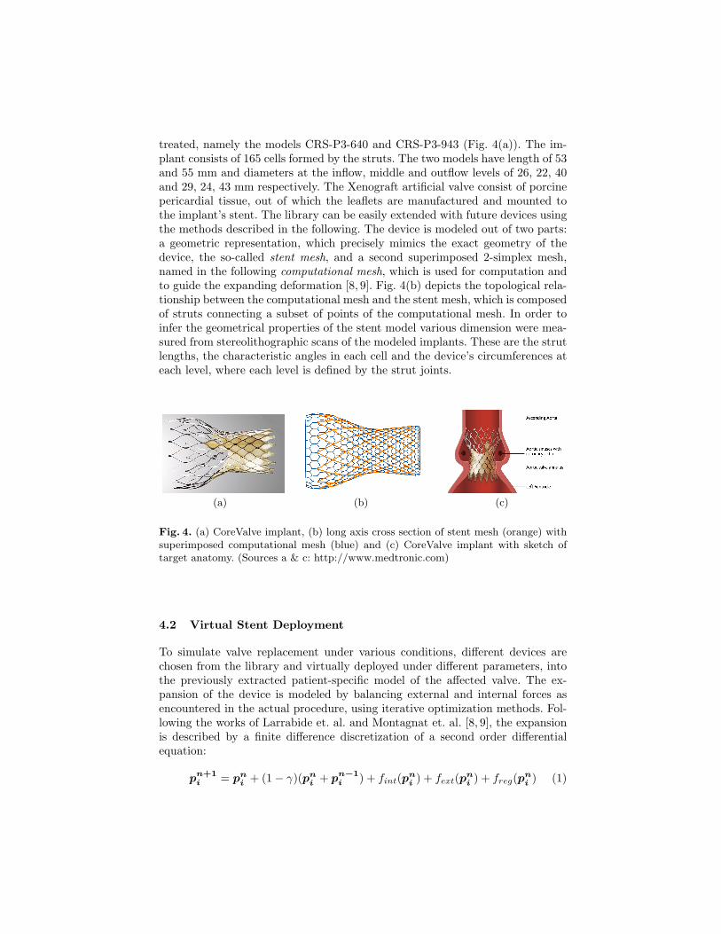
treated, namely the models CRS-P3-640 and CRS-P3-943 (Fig. 4(a)). The im-plant consists of 165 cells formed by the struts. The two models have length of 53and 55 mm and diameters at the inflow, middle and outflow levels of 26, 22, 40and 29, 24, 43 mm respectively. The Xenograft artificial valve consist of porcinepericardial tissue, out of which the leaflets are manufactured and mounted tothe implant’s stent. The library can be easily extended with future devices usingthe methods described in the following. The device is modeled out of two parts:a geometric representation, which precisely mimics the exact geometry of thedevice, the so-called stent mesh, and a second superimposed 2-simplex mesh,named in the following computational mesh, which is used for computation andto guide the expanding deformation [8, 9]. Fig. 4(b) depicts the topological rela-tionship between the computational mesh and the stent mesh, which is composedof struts connecting a subset of points of the computational mesh. In order toinfer the geometrical properties of the stent model various dimension were mea-sured from stereolithographic scans of the modeled implants. These are the strutlengths, the characteristic angles in each cell and the device’s circumferences ateach level, where each level is defined by the strut joints.
(a) (b) (c)
Fig. 4. (a) CoreValve implant, (b) long axis cross section of stent mesh (orange) withsuperimposed computational mesh (blue) and (c) CoreValve implant with sketch oftarget anatomy. (Sources a & c: http://www.medtronic.com)
4.2 Virtual Stent Deployment
To simulate valve replacement under various conditions, different devices arechosen from the library and virtually deployed under different parameters, intothe previously extracted patient-specific model of the affected valve. The ex-pansion of the device is modeled by balancing external and internal forces asencountered in the actual procedure, using iterative optimization methods. Fol-lowing the works of Larrabide et. al. and Montagnat et. al. [8, 9], the expansionis described by a finite difference discretization of a second order differentialequation:
pn+1i = pn
i + (1− γ)(pni + pn−1
i ) + fint(pni ) + fext(pn
i ) + freg(pni ) (1)
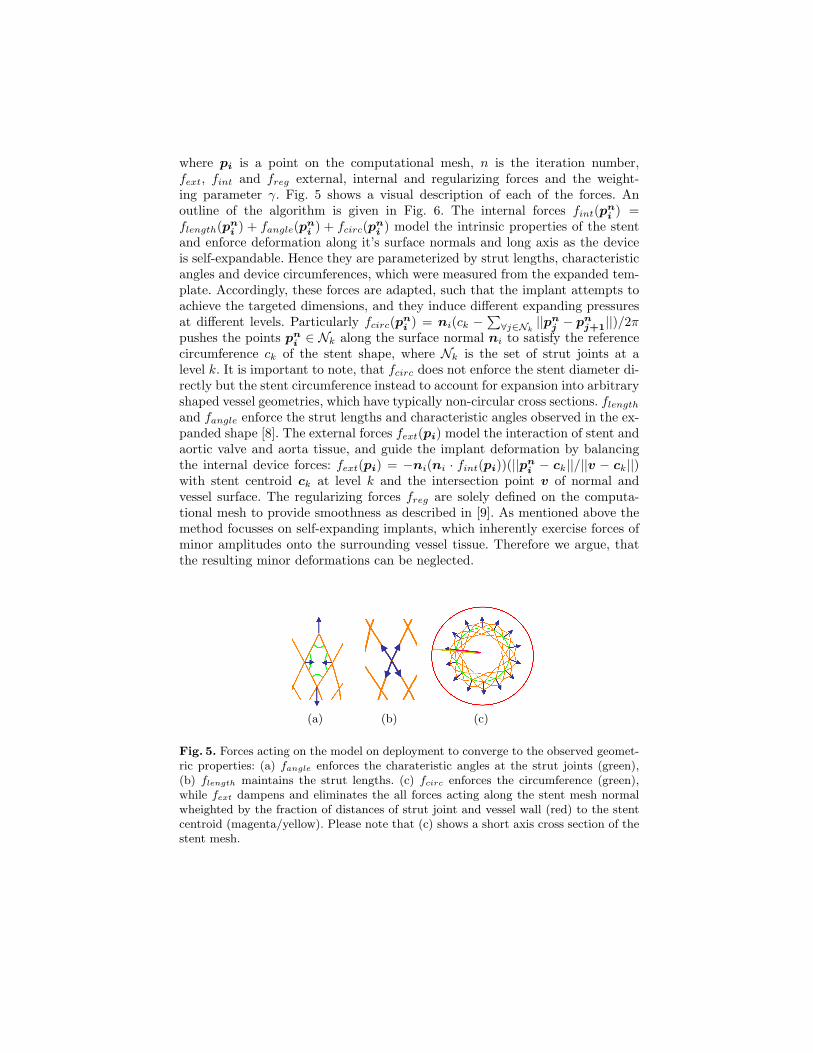
where pi is a point on the computational mesh, n is the iteration number,fext, fint and freg external, internal and regularizing forces and the weight-ing parameter γ. Fig. 5 shows a visual description of each of the forces. Anoutline of the algorithm is given in Fig. 6. The internal forces fint(pn
i ) =flength(pn
i ) + fangle(pni ) + fcirc(pn
i ) model the intrinsic properties of the stentand enforce deformation along it’s surface normals and long axis as the deviceis self-expandable. Hence they are parameterized by strut lengths, characteristicangles and device circumferences, which were measured from the expanded tem-plate. Accordingly, these forces are adapted, such that the implant attempts toachieve the targeted dimensions, and they induce different expanding pressuresat different levels. Particularly fcirc(pn
i ) = ni(ck −∑∀j∈Nk
||pnj − pn
j+1||)/2πpushes the points pn
i ∈ Nk along the surface normal ni to satisfy the referencecircumference ck of the stent shape, where Nk is the set of strut joints at alevel k. It is important to note, that fcirc does not enforce the stent diameter di-rectly but the stent circumference instead to account for expansion into arbitraryshaped vessel geometries, which have typically non-circular cross sections. flength
and fangle enforce the strut lengths and characteristic angles observed in the ex-panded shape [8]. The external forces fext(pi) model the interaction of stent andaortic valve and aorta tissue, and guide the implant deformation by balancingthe internal device forces: fext(pi) = −ni(ni · fint(pi))(||pn
i − ck||/||v − ck||)with stent centroid ck at level k and the intersection point v of normal andvessel surface. The regularizing forces freg are solely defined on the computa-tional mesh to provide smoothness as described in [9]. As mentioned above themethod focusses on self-expanding implants, which inherently exercise forces ofminor amplitudes onto the surrounding vessel tissue. Therefore we argue, thatthe resulting minor deformations can be neglected.
(a) (b) (c)
Fig. 5. Forces acting on the model on deployment to converge to the observed geomet-ric properties: (a) fangle enforces the charateristic angles at the strut joints (green),(b) flength maintains the strut lengths. (c) fcirc enforces the circumference (green),while fext dampens and eliminates the all forces acting along the stent mesh normalwheighted by the fraction of distances of strut joint and vessel wall (red) to the stentcentroid (magenta/yellow). Please note that (c) shows a short axis cross section of thestent mesh.
Input:
– Patient-specific model of aortic valve and aorta ascendens– implant placement position and orientation
Output: Deployed ImplantExecute:
– create computational mesh and stent mesh with constant radius of 1 mm at man-ually selected placement position, oriented along the aortic root centerline
– repeat:• for each point pn
i on the computational mesh, calculate freg(pni ), fangle(pn
i ),flength(pn
i ), fcirc(pni ) and fext(p
ni )
• for each pni , compute pn+1
i according to Eq. 1• if mean point displacement on the stent mesh < ε, convergence achieved; stop
execution
Fig. 6. The outline of our virtual stent deployment algorithm.
5 Experimental Results
The validation of the proposed framework is divided in two experiments. First wepresent results on the performance of the automatic patient-specific model esti-mation from pre- and post- cardiac CT data, as well as the quantitative variationbetween pre and postop ground truth anatomies, which is relevant for the subse-quent virtual imlant deployment. Second we validate the proposed in-silico im-plantation, by comparing predicted valve deployment, using pre-operative data,with real deployment from post-operative data.
5.1 Validation of Patient-Specific Anatomical Modeling andParameter Estimation
The data set used for patient-specific model estimation consists of 63 multi-phase(10 frames per cycle) cardiac CT and 21 single-phase cardiac CT acquisitions,which sums up to 651 CT volumes. Scans are acquired from different patientswith various cardiovascular diseases (including ascending aortic root aneurysm,regugitation, calcific stenosis and bicuspid aortic valves), using different pro-tocols, resulting in volumes with 80 to 350 slices and 153x153 up to 512x512voxel grid resolution and 0.28mm to 2.0mm spatial resolution. Each data set isassociated with an expert annotation used as ground-truth.
For the automatic patient-specific anatomical model estimation a combinedaccuracy of 1.45mm is obtained in 30sec on a standard desktop machine (IntelXeon 2.66Ghz, 2GB RAM) for both pre- and post-operative volumes. Perfor-mance is reported on test data, which represents randomized 20% of the completedataset, while the remaining 80% were used for training.
Due to different factors, a bias between the pre- and post-operative anatom-ical ground truth models can be expected. These are cardiac phase shifts and
image noise but also deformation of the aortic vessel wall due to stent deploy-ment, where the latter was assumed to be sufficiently small to be neglected inthe deployment algorithm (Sec. 4.2). Therefore we quantified the differences foreach pair of corresponding anatomical models obtained from a subset of 20 pa-tients with pre- and postoperative image data. The quantitative results in Table1 support the validity of our assumption, showing a mean relative deviation ofup to 6.46% between pre- and post-operative anatomies.
Table 1. Deviation of pre- and postoperative ground truth anatomical models: Differ-ences in diameter at sinutublar junction, valsava sinuses and aortic annulus are givenin absolute values as well as relative to the postoperative measurement. Values of Meanand standard deviation are provided as well as 80-percentile and maximum.
The validation of the in-silico implant deployment is performed on 20 patientswith pre- and post-operative cardiac CT images, affected by various diseasessuch as calcific stenosis as mentioned in the previous section. It is important tonote, that for this purpose the preoperative prediction result is compared withthe real device imaged in the postoperative data, where the latter serves as aground truth for this experiment.
The implant is virtually deployed into the associated anatomical model of thepreoperative volume using the algorithm described in Sec 4.2. In the postopera-tive volume the ground truth implant is manually placed and fit to the imagedstent, which is well visible in image data, using a semi-automatic method basedon the thin-plate-spline transformation. In the envisioned target application theoptimal deployment location and orientation is manually selected by the clini-cian. For validation purposes this is indirectly available and has to be inferred byregistering pre- and post-operative anatomical models. A selection of virtuallydeployed vs. their corresponding ground truth stents is depicted in Fig. 7. Theperformance is reported in Table 2 in terms of internal precision, by comparingonly the virtual and real implants shape in isolation via symmetric point-to-point distance, and external precision. The latter means to compare the virtualand real implants position relative to clinically relevant locations, in order toaccount for the potentially critical conditions due to wrong implant sizing andplacement such as blockage of coronary ostia and more importantly paravalvularleakages at the annular level as mentioned in Sec 1. This is done by computing
the differences of the pre- and postoperatively measured distances from annulusring and coronary ostia to the closest stent point respectively.
Table 2. Accuracy of in-silico valve deployment quantified from preop deploymentprediction vs. postop ground truth stent and measured in mm: besides point-to-pointdistance, accuracy relative to the anatomies was estimated from the differences indistances between aortic valve annulus and coronary ostia and implant. Values of meanand standard deviation are provided as well as 80-percentile and maximum.
In the clinical context, the required accuracy is proportional to the tolerancebetween therapeutical alternatives. Considering the diameter differences of 3mm(at the annular level) of the Medtronic CoreValve implants (Sec 4.1), the systemprovides a sufficient approximation in at least 80% of the cases for prevention ofparavalvular leakages, with an external accuracy of up to 1.4mm at the annularlevel. The algorithm performed at an average speed of 55sec on a standarddesktop machine (Intel Xeon 2.66Ghz, 2GB RAM). Thus our framework enablesfor fast and efficient preoperative planning and risk minimization by findingthe best implant type, size and deployment location and orientation via varyingthese parameters until optimal predicted performance is observed.
6 DiscussionIn this paper a framework for computational decision support for percutaneousaortic valve implantation was presented. A fast and robust estimation of ananatomical model enables for precise modeling of the patient-specific morphol-ogy and is consequently used for in-silico implant deployment. The approachwas validated with pre- and post-operative data sets from 20 patients and showsreasonable accuracy within the variation in appearance given by image and mo-tion artifacts. To the best of our knowledge, this is the first time a computa-tional framework is validated using real pre- and postoperative patient data. Theframework is targeted for fast and efficient preoperative planning with a libraryof different implants, intraoperative guidance and postoperative assessment ofinterventional outcome. It may have impact on the cardiology of the future andimprove the OR towards increased transparency.
References
1. Grube, E., Laborde, J., Gerckens, U., Felderhoff, T., Sauren, B., Buellesfeld, L.,Mueller, R., Menichelli, M., Schmidt, T., Zickmann, B., Iversen, S., Stone, G.W.:
(a) (b) (c) (d)
(e) (f) (g) (h)
Fig. 7. Example results of preoperative virtual stent deployment (a-d) vs. postoper-ative ground truth stents (e-h) overlayed with with the anatomical models. Note thedeviation of the virtually deployed stent around the sinutubular junction (upper end)in contrast to the close approximation at sinus and annular level, which is to due tothe fact, that internal stiffness of the stent configuration is not modeled yet.
Percutaneous implantation of the corevalve self-expanding valve prosthesis in high-risk patients with aortic valve disease. Circulation (114) (2006) 1616–1624
2. Lloyd-Jones, D., et. al.: Heart disease and stroke statistics - 2009 update. Circulation(2009)
3. Otto, C., Bonow, R.: Valvular Heart Disease: A Companion to Braunwald’s HeartDisease. Saunders (2009)
4. Grbic, S., Ionasec, R.I., Zheng, Y., Zaeuner, D., Georgescu, B., Comaniciu, D.:Aortic valve and ascending aortic root modeling from 3d and 3d+t ct. In: SPIEMedical Imaging, San Diego, USA (February 2010)
5. Ionasec, R.I., Voigt, I., Georgescu, B., Houle, H., Hornegger, J., Navab, N., Comani-ciu, D.: Modeling and assessment of the aortic-mitral valve coupling from 4d teeand ct. In: Proc. MICCAI, London, USA (September 2009)
6. Zheng, Y., Georgescu, B., Ling, H., Zhou, S.K., Scheuering, M., Comaniciu, D.:Constrained marginal space learning for efficient 3d anatomical structure detectionin medical images. In: CVPR. (2009) 194–201
7. Tu, Z.: Probabilistic boosting-tree: Learning discriminative models for classification,recognition, and clustering. In: Proc. ICCV, Washington, DC, USA (2005) 1589–1596
8. Larrabide, I., Radaelli, A., Frangi, A.F.: Fast virtual stenting with deformablemeshes: Application to intracranial aneurysms. In: MICCAI (2). (2008) 790–797
9. Montagnat, J., Delingette, H.: 4d deformable models with temporal constraints : ap-plication to 4d cardiac image segmentation. Medical Image Analysis 9(1) (February2005) 87–100