Page 1
Computer-aided Architecture Design and Optimized Implementation of Distributed Automotive EE Systems
Computer-aided Architecture Design and Optimized Implementation of Distributed Automotive EE Systems
Ajay Kumar, Antal Rajnak
Automotive ProgramsSystem Level Engineering Division
June 06, 2007DAC 07, Paper 31.4
Page 2
Presentation OutlinePresentation Outline
Problem statement
Basic AUTOSAR concepts
Proposed Tool Flow
Experience thus far
Suggested improvements / future work
Summary
Page 3
Current Design EnvironmentCurrent Design Environment Manual process with inadequate tool support Insufficient data to support early decision making,
leading to early binding and late verification. ECU-focused rather than system-level Validation on physical prototypes Distributed, multi-company, modular supply chain Few if any widely-accepted standards The resulting architectures are seldom optimal in
terms of:
Performance Flexibility / Scalability Reliability Life-cycle Cost
Page 4
Industry trendsIndustry trends
Increasing use of model-based function development 20-25% of all EE functions covered today
Used for: Functional verification Executable specification OEM -> Tier1
Major standardization effort - AUTOSAR Version 2.1 of specs released – matured Use gaining momentum in Europe US and Japan watching closely
Step towards development and validation in a virtual environment, using Systems Engineering principles
Page 5
Basic AUTOSAR conceptsBasic AUTOSAR concepts
AUTomotive Open System ARchitecture
Layered software architecture, with clearly defined interfaces
Applications implemented as atomic or composed Software Components (SWC)
Virtual Function Bus (VFB) – abstraction of all interconnected SWCs, communicating exclusively through ports independent of underlying hardware
Run Time Environment (RTE) – implementation of the VFB on a particular ECU
Basic Software (BSW) – implementation of the AUTOSAR infrastructure (nearly 40 different modules)
Page 6
AUTOSAR ECU sw structure
source: www.autosar.org
AUTOSAR ECU sw structure
source: www.autosar.org
Page 7
Basic AUTOSAR concepts (Cont.)Basic AUTOSAR concepts (Cont.)
AUTOSAR systems are described by a set of XML based Description Files Derived from a defined UML metamodel
What’s described: ECUs, SWCs, their mapping to ECUs, ECU interconnections etc.
What’s missing: Methodology to create these description files
Page 8
The Implementation AbyssThe Implementation Abyss
Model based function design – a widely accepted,and used technique
AUTOSAR – brings new level of abstraction to function implementers
But…
The task to translate a model based design into a robust, and efficient system, in a highly distributed environment remains a challenge.
How to bridge the implementation abyss?
Page 9
Proposed SLD methodologyProposed SLD methodology
Architecture Design Topology definition SWC to ECU Vehicle function creation mapping VFB-level simulation Bus scheduling Initial ECU Scheduling Metrics generation
ECU configuration Runnables to task mapping OS task scheduling Configuration of remaining BSW modules
Page 10
Proposed System Level Tool ChainProposed System Level Tool Chain
Implemented as a set of well connected point-tools.
Vehicle System Architect – for the OEMs
Function Editor Topology Editor Function Mapper
VFB-level Simulator Network Cluster Builder ECU Scheduler
Harness Design Tool (Capital Harness®) Metrics Generator
Vehicle System Builder – for the Tier 1s
Page 11
Proposed Tool FlowProposed Tool Flow
Vehicle
Features
Vehicle
Function
Editor
Vehicle Topology
Editor
&
Vehicle FunctionMapper
VFB level simulator
Network Cluster
Builder & ECU
scheduler
WiringHarness
Design Tool
MetricsGenerator
Optimized
Vehicle
Architecture
Description
Page 12
Tool Implementation ChallengesTool Implementation Challenges
Support for concept evaluation for EE-systems in early phases of the design process, when the available level of detail is minimal
Connectivity to legacy OEM environments
Scalable tool functionality, depending on OEM preferences Manual / Interactive use mode Analysis Synthesis – requirements based design
Page 13
Vehicle Function EditorVehicle Function Editor
Users create atomic or composed SWCs representing vehicle functions
Method: Manual graphical entry Import from function modeling tools
(e.g. Matlab/Simulink)
“Envelope” of function is adequate
Interface consistency is checked
Page 14
Vehicle Topology EditorVehicle Topology Editor
Instantiation of basic elements of the physical architecture (ECU-s, sensors, actuators, buses etc.)
Allows creation of “soft” (only partially defined) components in the early phases of design.
Import: Individual components Pre-existing message matrix Pre-existing topology
Graphically arrange components to form desired physical architecture.
Page 15
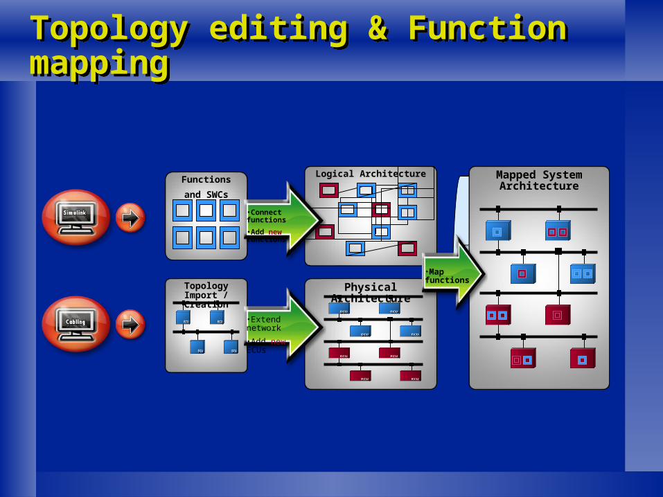
Topology editing & Function mappingTopology editing & Function mapping
Network Generation
Topology Import / Creation
Functions
and SWCs
Physical Architecture
•Extend network
•Add new ECUs
Logical Architecture
•Connect functions
•Add new functions
Mapped System Architecture
•Map functions
Page 16
Vehicle Function MapperVehicle Function Mapper
Function:
Mapping of vehicle functions to logical ECUs
Check of resource demand vs. availability
Soft ECUs allocated to real ECUs from library
Split of end to end timing requirements btw ECUs and buses
Automatic gateway configuration
Output: System Configuration Description file
ECU extract of SCD
Export to Harness design tool
Page 17
VFB-level SimulationVFB-level Simulation
VFB-level view: network of SWCs connected through ports
This network can be simulated Appropriately compiled SWCs with behavior required
Verify desired functionality across single, as well as multiple ECUs
Page 18
Network Scheduling – the Cluster BuilderNetwork Scheduling – the Cluster Builder
Basic Functionality: Produces schedule tables
Creation/modification of frames (PDU-s) and related parameters (ID, period time, x-fer mode etc.)
Interactive signal packing and editing of schedule tables
Cluster schedulability analysis
Expanded functionality:
Automatic frame compilers (AFC-s) for CAN/LIN/FlexRay
Fully automatic scheduling and frame packing
Page 19
ECU SchedulerECU Scheduler
Runnables to tasks mapping
Manual configuration and schedulability analysis based on available timing information
Configuration of OS and BSW schedulers
Tightly coupled to network scheduling.
Page 20
Unified Timing ModelUnified Timing Model
SENSOR SWC BSW
BUS
BSW GATEWAY
BUS
BSW
APPLICATION SWC
BSW
BUS
BSW
ACTUATOR SWC
ACTU-ATOR
SEN-SOR
BSW
BSW
PUBLISHER LATENCY
SUBSCRIBER LATENCY
SWC PROP. DELAY
GW DELAY
BUS PROP. DELAY
BUS PROP. DELAY
BUS PROP. DELAY
SENSOR SWC
APPLICATION SWC
ACTUATOR SWC
Termin-ator
Termi-nator
MAX. AGE
LEVEL 1: VEHICLE FUNCTION LEVEL (AUTOSAR VFB VIEW)
LEVEL 2: VEHICLE ARCHITECTURE LEVEL
Page 21
Metrics generationMetrics generation
Compares and ranks a set of alternative architectural solutions in relative terms
Component cost is only one aspect - scalability, flexibility and extensibility will heavily influence the results.
Scenario based sensitivity analysis is essential to identify decision points
Simplified analysis running in the background provides ”live” feedback to user
Page 22
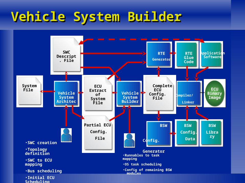
Vehicle System BuilderVehicle System Builder
Function:
Create/edit all AUTOSAR-relatedconfiguration files
Intelligently merge partial configuration filesfrom multiple sources
Generate a downloadable binary image of the complete software (Apps+BSW+Config) for the selected ECU.
Page 23
Vehicle System BuilderVehicle System Builder
SystemFile
Vehicle System
Architect
ECU Extract
of System
File
SWCDescript.
File
Partial ECU
Config.
File
Vehicle System Builder
CompleteECU
Config.File
Compiler/
Linker
BSW
Config.
Generator
RTE
Generator
ECU BinaryImage
RTE GlueCode
ApplicationSoftware
BSW
Config.
Data
BSW
Library
•SWC creation
•Topology definition
•SWC to ECU mapping
•Bus scheduling
•Initial ECU Scheduling
•Runnables to task mapping
•OS task scheduling
•Config of remaining BSW modules
Page 24
Correctness by DesignCorrectness by Design Vision:
Requirements based Systems Engineering Process
Holistic, top-down approach, supported by well connected high-level tools.
Development and validation in a virtual environment
Values: Reduced cost Shortened lead-times Improved Reliability & Quality
Page 25
Experience thus farExperience thus far
Tool-set for requirements based synthesis of complex CAN and LIN networks and gateways successfully deployed and used in production since 1998 (Volcano Network Architect tool).
Users are enthusiastic!
But...
Timing analysis is not widely used in current automotive design flows.
Page 26
Suggested improvements / future workSuggested improvements / future work
Enhanced AUTOSAR Timing Model – to cover important concepts, i.e. jitter, phasing, or precedence required to deal with complex systems
Coordinated AUTOSAR Metamodel extensions
Evaluation metrics refinement Define objective metrics and evaluation
algorithms to judge:
Scalability Flexibility
Page 27
SummarySummary
Bridging the implementation abyss between model based function design and creation of efficient AUTOSAR implementations calls for new methods, and advanced tool support.
Challenges: Usability in early project phases, when only limited
amount of data is available Need to support a flexible set of usage models:
(interactive, analytic or full synthesis)
The required technology is readily available
The AUTOSAR Timing model needs major re-work
Page 28
Thank you!
Q&A...Q&A...