INRODUCTIONDrag line is a heavy duty mechanical hardwareused for removal of overburden in opencastmine. it is similar to a crane in which hoisting,dragging and swinging operation of bucketsare possible over and above these, a walkingmechanism is provided with the help of which
ISSN 2278 – 0149 www.ijmerr.comVol. 2, No. 2, April 2013
1 Department of Mech. Engg., Priyadarshini Indira Gandhi College of Engg., Nagpur, India.
entire platform of dragline can be shifted fromone location to another.
Out of 31 open cast mines of W.C.L only3 mines are having drag line.
These are
• Umred opencast mine (Nagpur district).
Research Paper
126
Int. J. Mech. Eng. & Rob. Res. 2013 Shrikant Awatade and Umesh Bokade, 2013
• Sasti opencast mine (Chandrapur district).
• Ghugus opencast mine (Chandrapurdistrict).
Specification of Drag Line 15/90Umred• Machine commissioned in -1978
• Bucket capacity -15 m3
• Boom length -90 m
• Motor supply -1900 kw
• Machine weight -1600 tones
• Walking speed -60 m/hr
• Dragging radius -80 m
Computer Aided Modelingof Bull Gear
Modelling Procedure of Bull Gear
Modeling and drafting of bull gear is done inpro-e software. The various tools used formodeling of bull gear is revolve, extrude,chamfer, round, pattern.
Various steps in modelling are as follows:
• Sketch dedendum circle and then extrude.
• Sketch the one teeth profile and thenextrude.
• Pattern the teeth.
• Sketch one arm of gear and then extrude.
• Pattern the arm.
• Sketch the one hole.
• Pattern the holes.
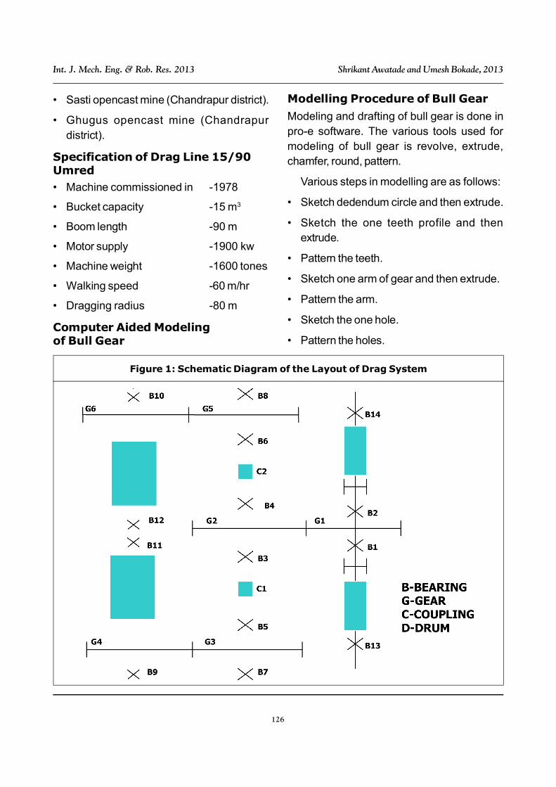
Figure 1: Schematic Diagram of the Layout of Drag System
127
Int. J. Mech. Eng. & Rob. Res. 2013 Shrikant Awatade and Umesh Bokade, 2013
FINITE ELEMENT APPROACH
Finite Element MethodologyThe solution of a general continuum problemby the finite element method always follows anorderly step by step process. With referenceto static structural problems, the step by stepprocedure can be stated as follows:
Step 1: Discretization of theStructureThe first step in the finite element method is todivide the structure or solution region intosubdivisions or elements. Hence the structureis to be modeled with suitable finite elements.The number, type, size and arrangements ofthe elements are to be decided.
Step 2: Selection of ProperInterpolation or Displacement ModelSince the displacement solution of a complexstructure under any specified load conditionscannot be predicted exactly, we assume somesuitable solution within an element toapproximate the unknown solution. Theassumed solution must be simple form acomputational point of view, but it should satisfycertain convergence requirements. In general,the solution or the interpolation model is takenin the form of a polynomial.
To satisfy the convergence requirements,the polynomial functions,
• Must be continuous within the element
• Must contain rigid body displacement orfield variables
• Must contain constant strain states
Step 3: Derivation of ElementStiffness Matrices and Load VectorsFor the assumed displacement model, thestiffness matrix ke and the load vector Fe of
Figure 2: Modelling of Bull Gear
DRAFTING OF BULL GEAR
Figure 3: Drafting of Bull Gear
(a)
(b)
128
Int. J. Mech. Eng. & Rob. Res. 2013 Shrikant Awatade and Umesh Bokade, 2013
element “e” are to be derived by using eitherequilibrium conditions or a suitable variationalprinciple.
Step 4: Assemblage of ElementalEquations to Obtain the OverallEquilibrium Equations
Since the structure is composed of severalfinite elements, the individual elementalstiffness matrices and load vectors are to beassembled in a suitable manner and the overallequilibrium equations have to be formulatedas [k]u = F. Where [k] is assembled stiffnessmatrix, u the vector of nodal displacements andP is called the vector nodal forces for thecomplex structure.
Step 5: Solution for the UnknownNodal Displacements
The overall equilibrium equations have to bemodified to account for the boundaryconditions of the problem. After theincorporation of the boundary conditions, the
equilibrium equations can be expressed as[k]u = F.
For linear problems, the vector u is can besolved very easily. But for nonlinear problems,the solution has to be obtained in a sequenceof steps, each step involving the modificationof the stiffness matrix [k] and/or load vector F.
Step 6: Computational of ElementalStress and Strains
For the known nodal displacements u, ifrequired the elemental strains and stressescan be computed by using the necessaryequations of solid or structural mechanics.
The terminology used in the above six stepshas to be modified if we want to extend theconcept to other fields.
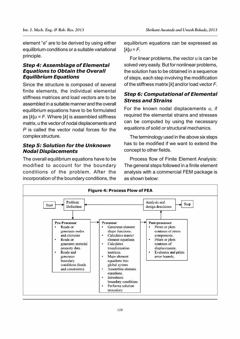
Process flow of Finite Element Analysis:The general steps followed in a finite elementanalysis with a commercial FEM package isas shown below:
Figure 4: Process Flow of FEA
129
Int. J. Mech. Eng. & Rob. Res. 2013 Shrikant Awatade and Umesh Bokade, 2013
METHOD OF ANALYSISElement type = Tet 10node 187
Number of nodes = 203252
Number of elements = 144664
Material property:
Young’s modulus of Elasticity = 202 Gpa
Poisson’s ratio = 0.3
Material of gear-CAST STEEL grade-I
Analysis is done in Ansys software. Firststep in analysis is to import bull gear teeth frompro-e software, then defining the variousstages of Ansys. Which are as follows.
Preferences
Type of analysis-structural
P-method
Preprocessor
• Material property-
– Modulus of elasticity-200 GPa
– Posssion’s ratio-0.3
• Element
– Solid (Tet 10 node 187)
• Meshing
– Mesh tool-free mesh-by volume
Solution
In this we are apply boundary condition
Force (Ft) = 87394.43 N
Displacement Fx = Fy = Fz = 0
Post Processor
Obtaining the solution, such as nodal solution,Element solution, vonmisses stresses,vonmisses strain, nodal displacement.
• Plot result – Nodal solution-deformationresult
• Plot result – Element solution-deformationresult
• Plot result – Element solution-stress-vonmisses stress
• Plot result – Element solution- stress-vonmisses strain
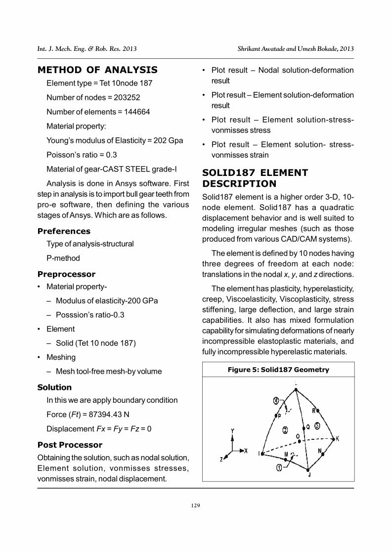
SOLID187 ELEMENTDESCRIPTIONSolid187 element is a higher order 3-D, 10-node element. Solid187 has a quadraticdisplacement behavior and is well suited tomodeling irregular meshes (such as thoseproduced from various CAD/CAM systems).
The element is defined by 10 nodes havingthree degrees of freedom at each node:translations in the nodal x, y, and z directions.
The element has plasticity, hyperelasticity,creep, Viscoelasticity, Viscoplasticity, stressstiffening, large deflection, and large straincapabilities. It also has mixed formulationcapability for simulating deformations of nearlyincompressible elastoplastic materials, andfully incompressible hyperelastic materials.
Figure 5: Solid187 Geometry
130
Int. J. Mech. Eng. & Rob. Res. 2013 Shrikant Awatade and Umesh Bokade, 2013
(Dynamic load at pitch circle radius) x (Pitchcircle radius) = (Equivalent tip load) x(Addendum circle radius)
137330.9 * 1339 = Equivalent tip load *1365
Equivalent tip load = 134715 N
Figure 19: For Force = 134715 NDeflection = 0.0306 mm
Figure 20: Vonmisses Stress 515.19 mpa
Figure 21: Vonmisses Strain 0.00255 mpa
133
Int. J. Mech. Eng. & Rob. Res. 2013 Shrikant Awatade and Umesh Bokade, 2013
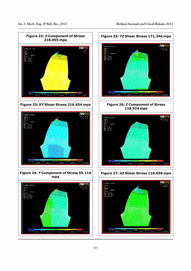
Figure 22: X Component of Stress218.055 mpa
Figure 23: XY Shear Stress 216.454 mpa
Figure 24: Y Component of Stress 55.116mpa
Figure 25: YZ Shear Stress 171.344 mpa
Figure 26: Z Component of Stress118.524 mpa
Figure 27: XZ Shear Stress 118.658 mpa
134
Int. J. Mech. Eng. & Rob. Res. 2013 Shrikant Awatade and Umesh Bokade, 2013
RESULTS AND DISCUSSION
Conference on Robotics and AutomationSydney, November 14-15.
5. Reddy J N (1977), Finite ElementsMethod, TaTa McGraw-Hill Edition.
6. Robert D Cook (1989), Concept &Application of Finite Elements Method,3rd Edition, John Wiley & Sons.
7. Robert I Norton (1996), Machine Designan Integrated Approach, Upper SddleRiver, Prentice Hall.
8. Shiwalkar B D (1990), Design of MachineElements, Central Techno Publication,Nagpur.
9. Sonpimple M K Phirke (2007), CADModeling & Analysis of Dam Gate LiftingHoist Mechanism, Proceeding ofIFToMM.
10. Tirupathi R Chandrupatla and Ashok DBelegunda (2007), Introduction to FiniteElements in Engineering, PearsonEducation.
11. Zeping Wei (2004), Stresses andDeformations in Involute Spur Gears byFinite Element Method.
Result Ft = 87394.43 N Ft = 134715 N % Increase
Deflection 0.019181 mm 0.0306 mm 59%
X Component of Stress 102.034 mpa 218.055 mpa 113%
Y Component of Stress 99.702 mpa 171.344 mpa 71%
Z Component of Stress 66.551 mpa 118.524 mpa 78%
XY Shear Stress 112.655 mpa 216.454 mpa 92%
YZ Shear Stress 25.884 mpa 55.116 mpa 113%
XZ Shear Stress 25.899 mpa 118.658 mpa 358%
Equivalent Von Mises Stress 286.495 mpa 515.319 mpa 79%
Von Mises Strain 0.001418 0.00255 79%
Table 1: Comparison of Results
CONCLUSIONIn the present study, effective methods toestimate the root bending stresses by the finiteelement analysis.
It was found that for tooth load 87394.43 Nmaximum deflection is 0.19181 mm and thestresses is 286.495 mpa which is less thanthe maximum design stress, i.e., 433.33 mpafor material under consideration and also if theforce exceed 115000 N maximum deflectionis found to be 0.266 mm and stresses is443.623 mpa, which will break the tooth.
REFERENCES1. Joseph E Shingley (2003), Standard
Book of Machine Design, TaTa McGraw-Hill International Book Co.
2. Krishnamurti C S (1991), FEA Theory &Programming, 3rd Reprint, Tata McGrawHill Publishing Company Limited, NewDelhi.
3. Modak J P (2006), Vibration BasedCondition Monitoring of Drag Line, July.
4. Peter Ridley (2001), “Dragline Bucketand Rigging Dynamics”, Australian